1 §3 Basic Fibre Components Components to be studied ● Fiber joints ● 2x2 fiber couplers ●...
30
1 §3 Basic Fibre Components Components to be studied ●Fiber joints ●2x2 fiber couplers ● WDM couplers ● Fixed optical filters (FP and FBG filters) ● Tunable optical filters (FP and FBG filters) ● Isolators and circulators
-
Upload
asher-french -
Category
Documents
-
view
248 -
download
7
Transcript of 1 §3 Basic Fibre Components Components to be studied ● Fiber joints ● 2x2 fiber couplers ●...
1
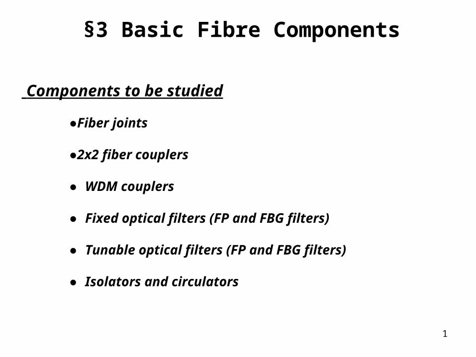
§3 Basic Fibre Components
Components to be studied
●Fiber joints
●2x2 fiber couplers
● WDM couplers
● Fixed optical filters (FP and FBG filters)
● Tunable optical filters (FP and FBG filters)
● Isolators and circulators
2
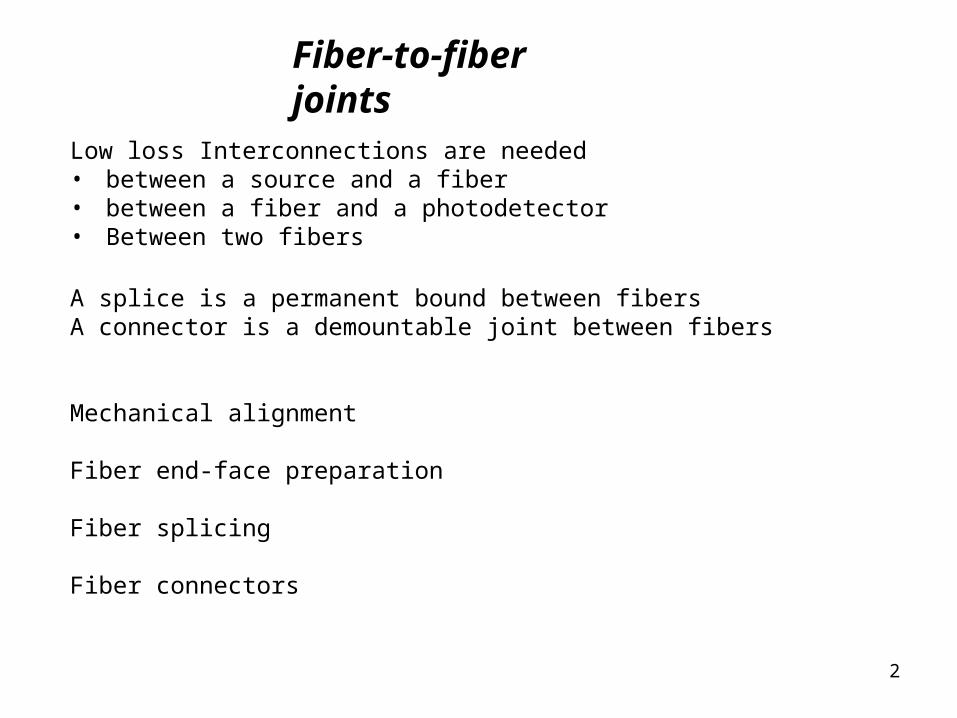
Fiber-to-fiber joints
Low loss Interconnections are needed • between a source and a fiber• between a fiber and a photodetector• Between two fibers
A splice is a permanent bound between fibersA connector is a demountable joint between fibers
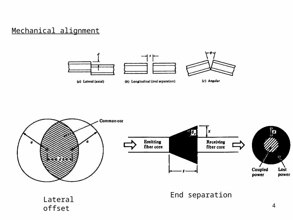
Mechanical alignment
Fiber end-face preparation
Fiber splicing
Fiber connectors
3
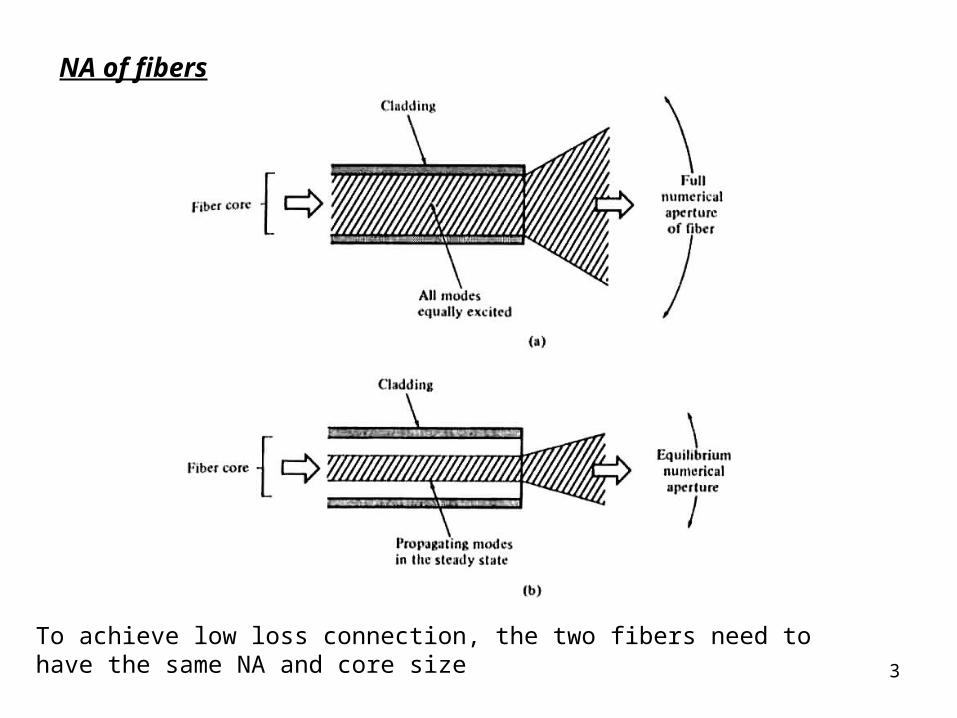
NA of fibers
To achieve low loss connection, the two fibers need to have the same NA and core size
4
Mechanical alignment
Lateral offset End separation
5
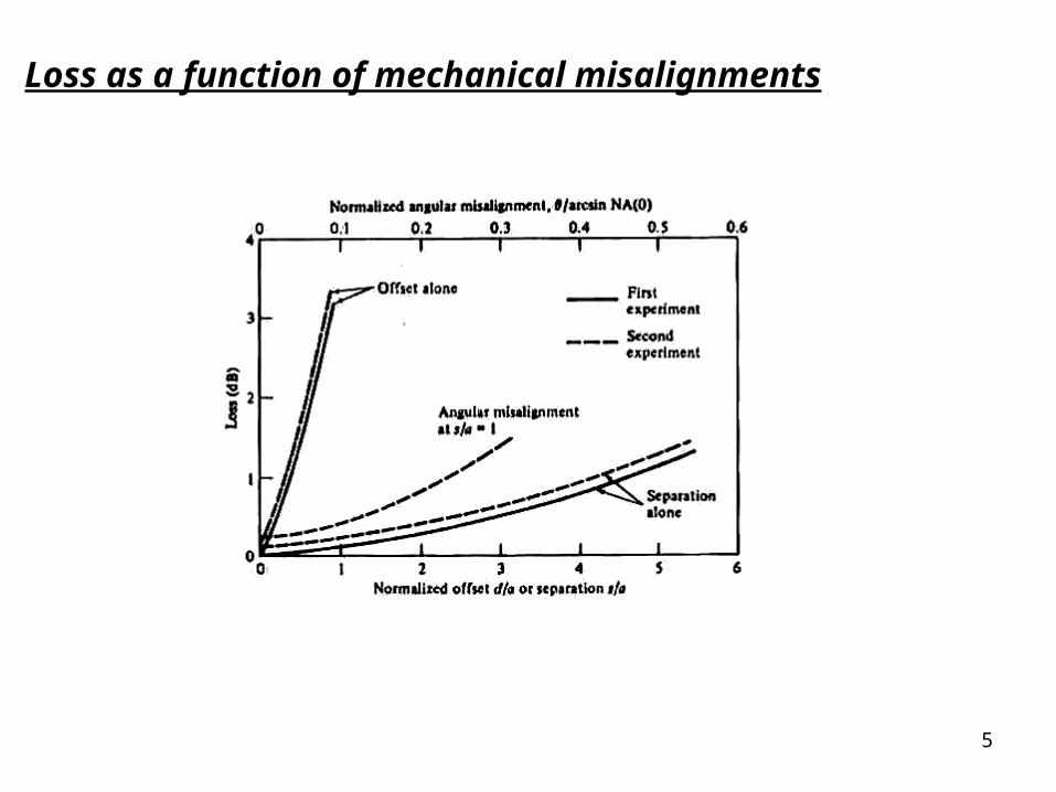
Loss as a function of mechanical misalignments
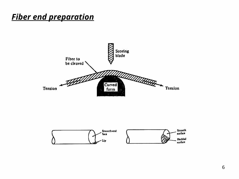
6
Fiber end preparation

7
Fusion splicing of optical fibers
V-groove splicing
8
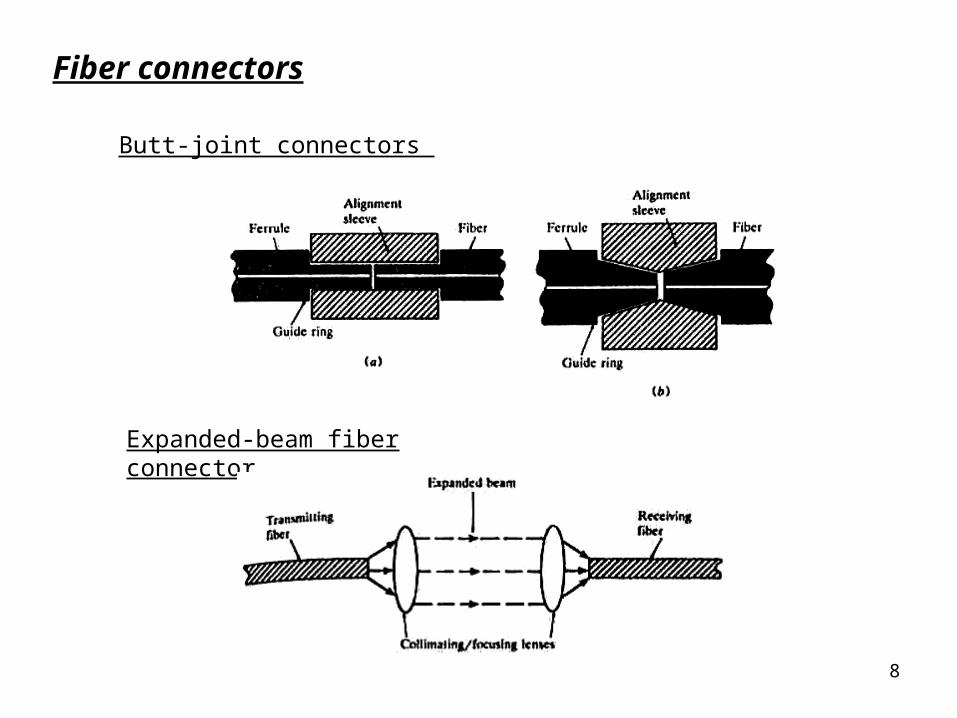
Butt-joint connectors
Expanded-beam fiber connector
Fiber connectors
9
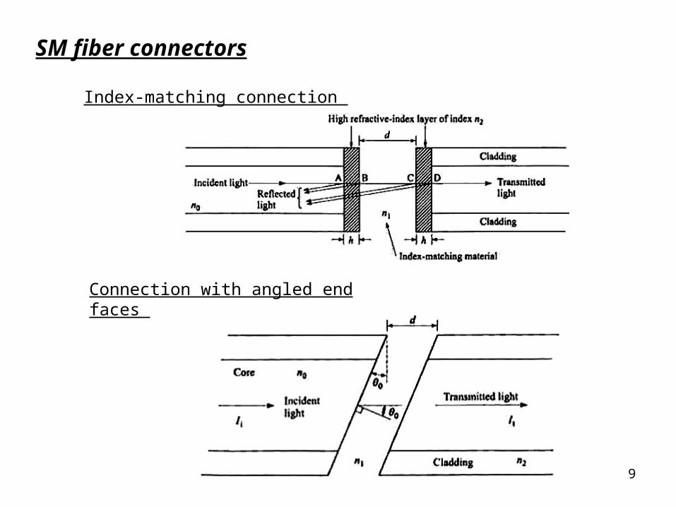
Index-matching connection
Connection with angled end faces
SM fiber connectors
10
P1
P2
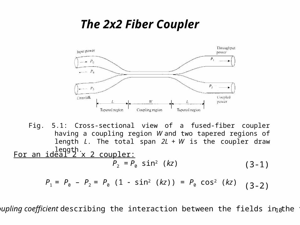
The 2x2 Fiber Coupler
Fig. 5.1: Cross-sectional view of a fused-fiber coupler having a coupling region W and two tapered regions of length L. The total span 2L + W is the coupler draw length.
For an ideal 2 x 2 coupler:P2 = P0 sin2 (kz) (3-1)
P1 = P0 – P2 = P0 (1 sin2 (kz)) = P0 cos2 (kz) (3-2)
k is the coupling coefficient describing the interaction between the fields in the two fibers
11
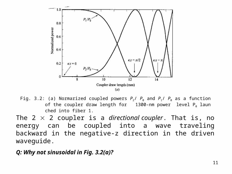
Fig. 3.2: (a) Normarized coupled powers P2/ P0 and P1/ P0 as a function of the coupler draw length for 1300-nm power level P0 launched into fiber 1.
The 2 2 coupler is a directional coupler. That is, no energy can be coupled into a wave traveling backward in the negative-z direction in the driven waveguide.
Q: Why not sinusoidal in Fig. 3.2(a)?
12
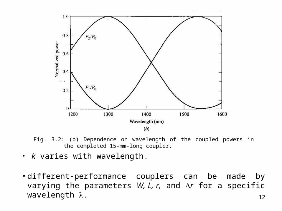
Fig. 3.2: (b) Dependence on wavelength of the coupled powers in the completed 15-mm-long coupler.
• k varies with wavelength.
• different-performance couplers can be made by varying the parameters W, L, r, and r for a specific wavelength .
13
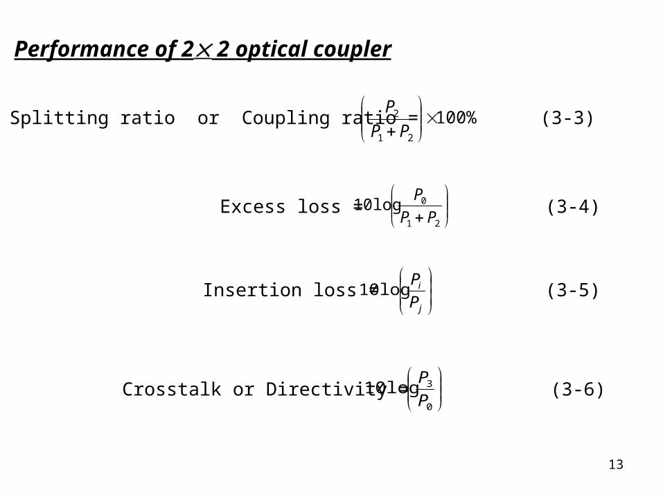
Performance of 2 2 optical coupler
Splitting ratio or Coupling ratio = 100%21
2
PP
P
Excess loss =
21
010logPP
P
Insertion loss =
j
i
P
P10log
Crosstalk or Directivity =
0
310logP
P
(3-3)
(3-4)
(3-5)
(3-6)
14
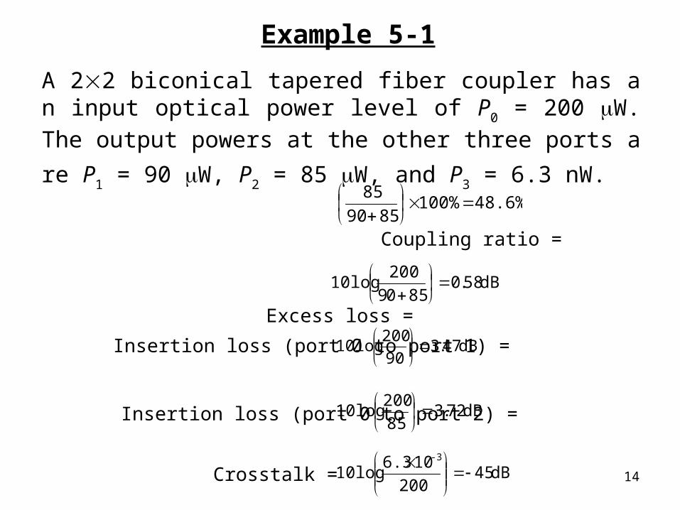
Example 5-1
A 22 biconical tapered fiber coupler has an input optical power level of P0 = 200 W. The output powers at the other three ports
are P1 = 90 W, P2 = 85 W, and P3 = 6.3 nW.
Coupling ratio =
Excess loss =
48.6% 100%8590
85
dB58.08509
20010log
Insertion loss (port 0 to port 1) =
Insertion loss (port 0 to port 2) =
dB47.390
20010log
dB72.385
20010log
Crosstalk = dB45200
106.310log
-3
15
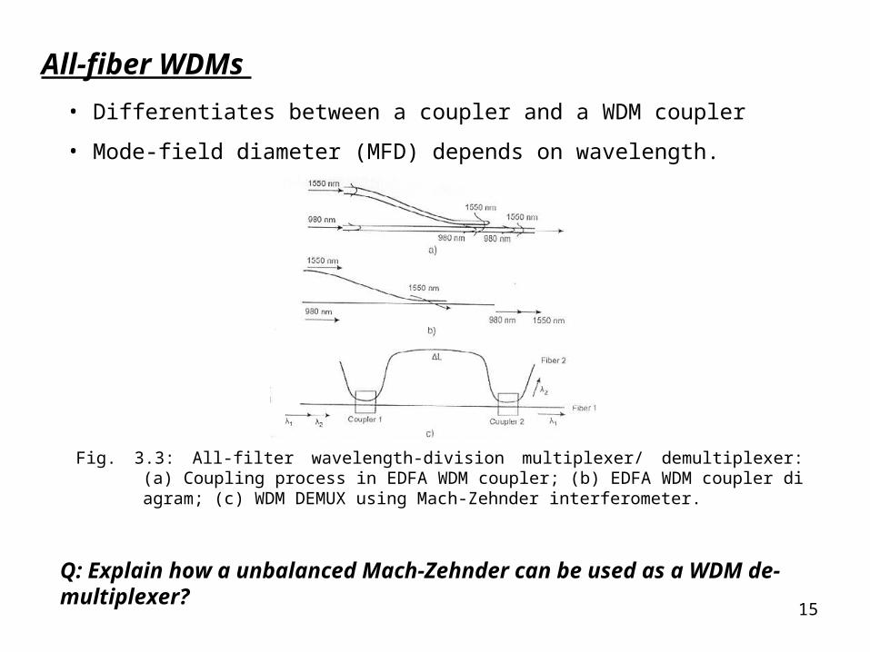
All-fiber WDMs
• Differentiates between a coupler and a WDM coupler
• Mode-field diameter (MFD) depends on wavelength.
Fig. 3.3: All-filter wavelength-division multiplexer/ demultiplexer: (a) Coupling process in EDFA WDM coupler; (b) EDFA WDM coupler diagram; (c) WDM DEMUX using Mach-Zehnder interferometer.
Q: Explain how a unbalanced Mach-Zehnder can be used as a WDM de-multiplexer?
16
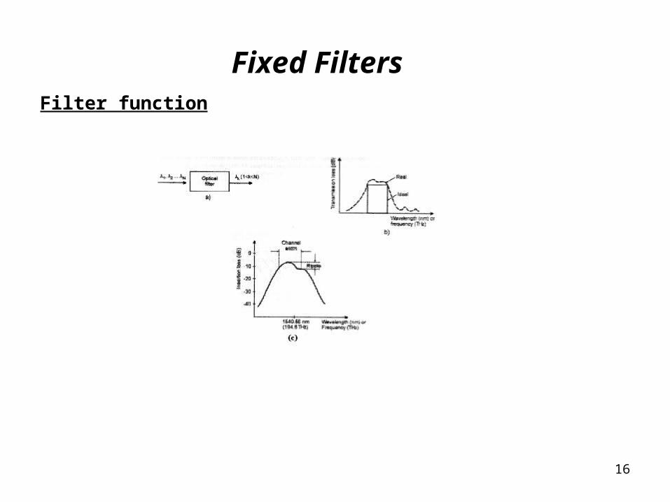
Fixed FiltersFilter function
17
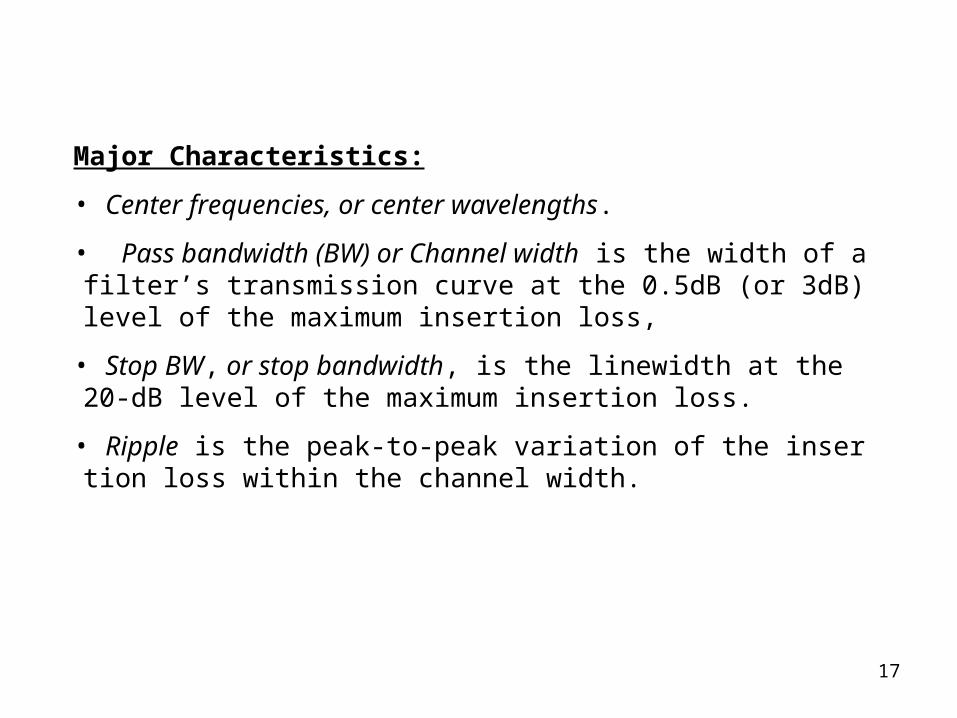
Major Characteristics:
• Center frequencies, or center wavelengths.
• Pass bandwidth (BW) or Channel width is the width of a filter’s transmission curve at the 0.5dB (or 3dB) level of the maximum insertion loss,
• Stop BW, or stop bandwidth, is the linewidth at the 20-dB level of the maximum insertion loss.
• Ripple is the peak-to-peak variation of the insertion loss within the channel width.

18
Fabry-Perot (F-P) filter:
Fig. 3.5: Operation of Fabry-Perot resonator and its transfer function.
LncLvFSR 2/2/
RRLncFWHMBWFPF /1)2/()(
vLRRRT mmmFPF /sin41/1 0222 Transfer function:
Free spectral range:
Bandwidth:
RRBWFSRF FPF 1// Finesse:

19
Fiber Bragg grating (FBG) filter
The fiber Bragg grating is the diffraction grating implemented as a variation of the refractive index of the fiber core.
Fig. 5.6: Fiber Bragg grating.
Bragg condition
Beffn 2 (4-17)
20
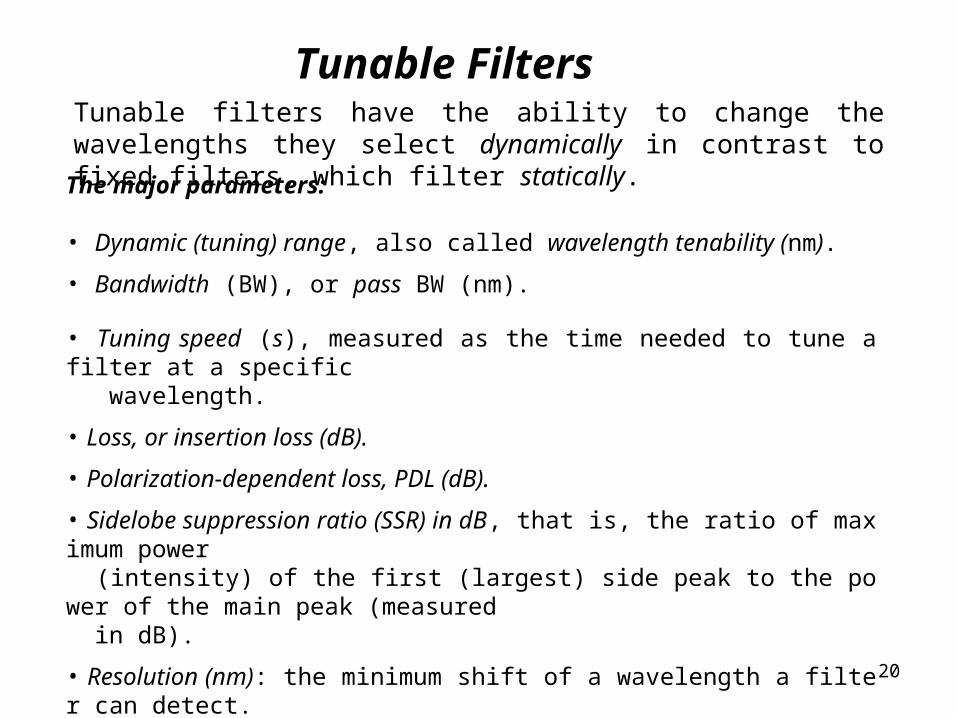
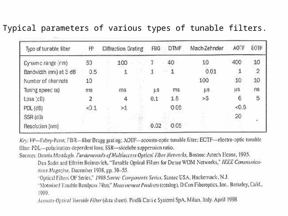
Tunable FiltersTunable filters have the ability to change the wavelengths they select dynamically in contrast to fixed filters, which filter statically.
The major parameters:
• Dynamic (tuning) range, also called wavelength tenability (nm).
• Bandwidth (BW), or pass BW (nm).
• Tuning speed (s), measured as the time needed to tune a filter at a specific wavelength.
• Loss, or insertion loss (dB).
• Polarization-dependent loss, PDL (dB).
• Sidelobe suppression ratio (SSR) in dB, that is, the ratio of maximum power (intensity) of the first (largest) side peak to the power of the main peak (measured in dB).
• Resolution (nm): the minimum shift of a wavelength a filter can detect.
21
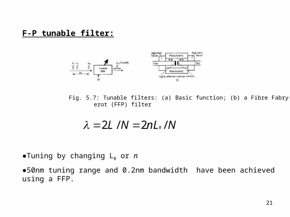
Fig. 5.7: Tunable filters: (a) Basic function; (b) a Fibre Fabry-Perot (FFP) filter
NnLNL /2/2 0
●Tuning by changing L0 or n
●50nm tuning range and 0.2nm bandwidth have been achieved using a FFP.
F-P tunable filter:
22
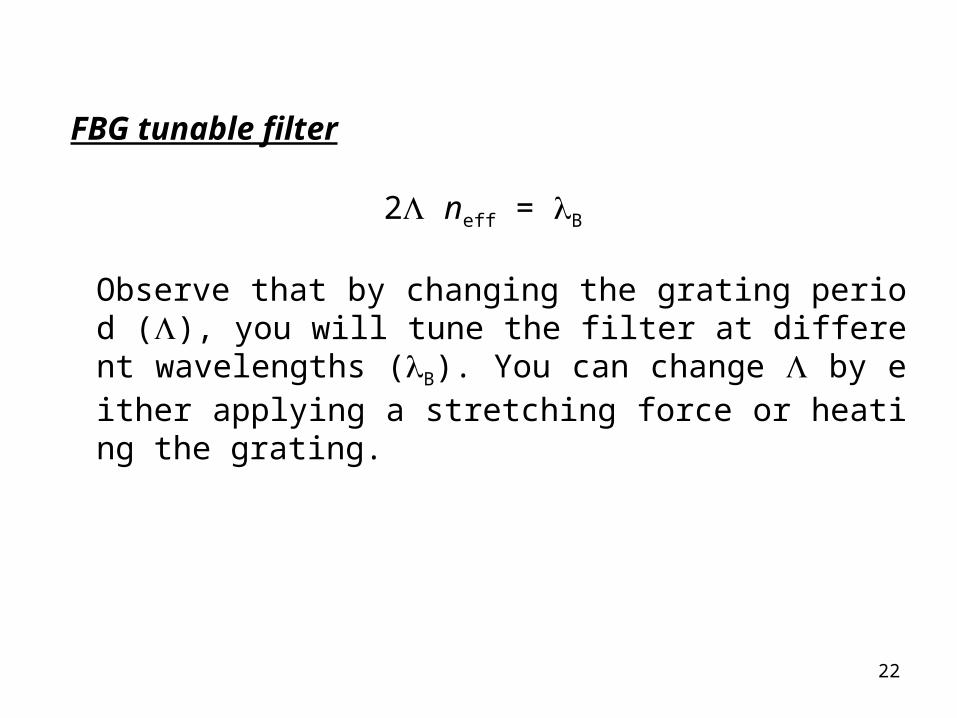
FBG tunable filter
2 neff = B
Observe that by changing the grating period (), you will tune the filter at different wavelengths (B). You can change by either applying a stretching force or heating the grating.
23
Table: Typical parameters of various types of tunable filters.
24
Isolators, Circulators, and Attenuators
Isolators
• Why isolators are needed:
components
system
• “isolate” lasers, EDFAs, SOAs, and other devices from backreflected light.
See Fig.3.8 (a)
• An isolator must allow the forward light to pass through with minimal (ideally,
zero) loss and block backreflected light with maximum (ideally, infinity) loss.
Insertion loss of a modern isolator could be as low as 0.15 dB, while isolation
could be as high 70dB.
25
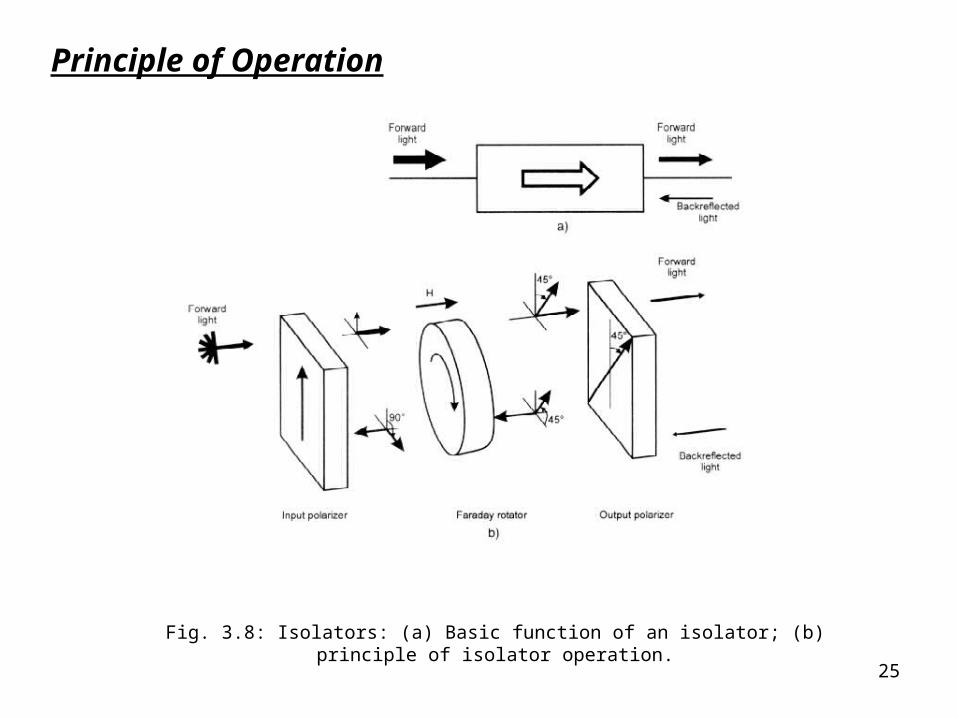
Principle of Operation
Fig. 3.8: Isolators: (a) Basic function of an isolator; (b) principle of isolator operation.
26
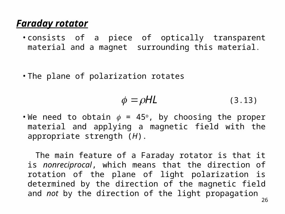
Faraday rotator
• consists of a piece of optically transparent material and a magnet surrounding this material.
• The plane of polarization rotates
HL (3.13)
• We need to obtain = 45o, by choosing the proper material and applying a magnetic field with the appropriate strength (H).
The main feature of a Faraday rotator is that it is nonreciprocal, which means that the direction of rotation of the plane of light polarization is determined by the direction of the magnetic field and not by the direction of the light propagation
27
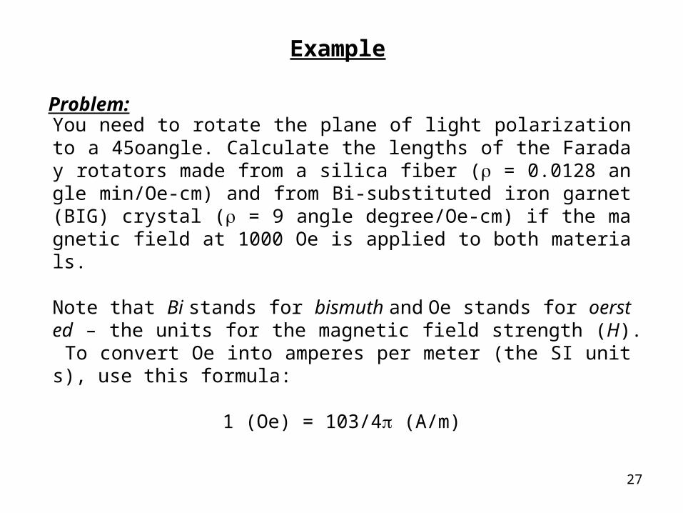
Example
Problem:
You need to rotate the plane of light polarization to a 45oangle. Calculate the lengths of the Faraday rotators made from a silica fiber ( = 0.0128 angle min/Oe-cm) and from Bi-substituted iron garnet (BIG) crystal ( = 9 angle degree/Oe-cm) if the magnetic field at 1000 Oe is applied to both materials.
Note that Bi stands for bismuth and Oe stands for oersted – the units for the magnetic field strength (H). To convert Oe into amperes per meter (the SI units), use this formula:
1 (Oe) = 103/4 (A/m)

28
For a silica fiber,Lfiber = 210.9 cm, not acceptable
For a Bi-substituted iron garnet crystal, Lcrystal = 0.05 nm, OK
Solution:
29
1. Polarization sensitivity. How to make a polarization insensitive isolator?2. Wavelength dependence. Transparency of garnet crystal. 3. Temperature sensitivity of Faraday-rotator material.
Problems in designing Isolators:
30
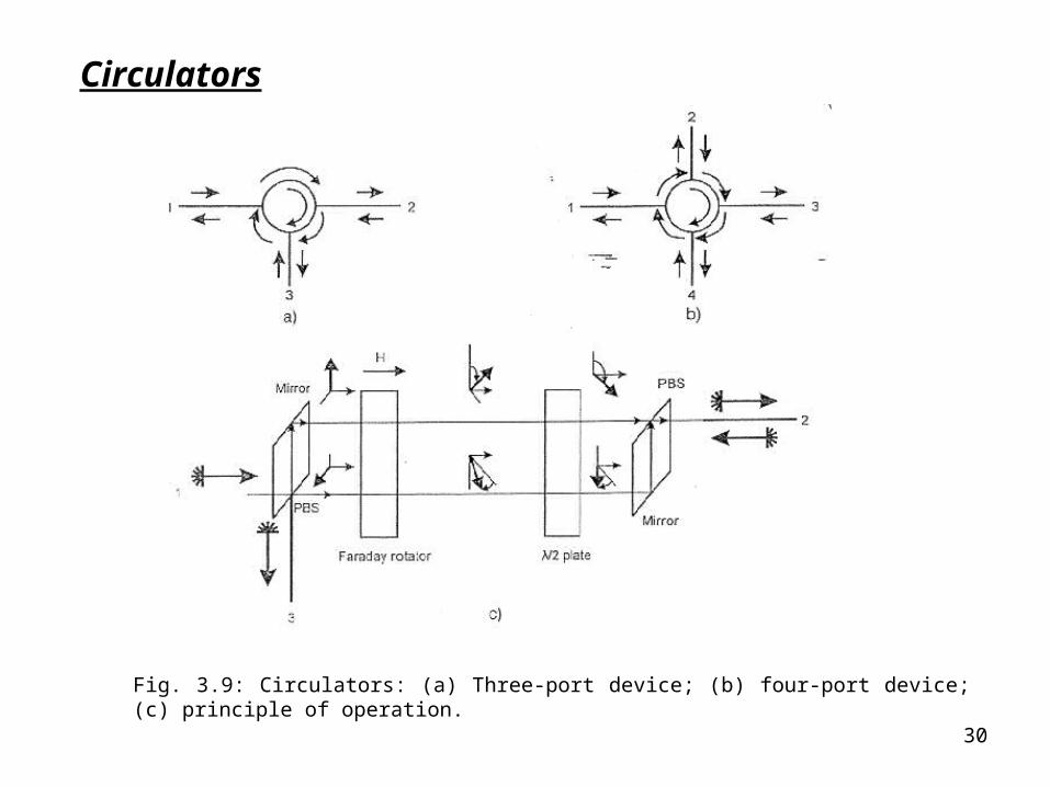
Circulators
Fig. 3.9: Circulators: (a) Three-port device; (b) four-port device; (c) principle of operation.