Fiber Joints and Couplers; Cable Design - Webs€¦ · Optical fiber couplers are passive devices...
23
Fiber Joints and Couplers; Cable Design Dr. Mohammad Faisal Dept. of EEE, BUET
Transcript of Fiber Joints and Couplers; Cable Design - Webs€¦ · Optical fiber couplers are passive devices...
Fiber Joints and Couplers;
Cable Design
Dr. Mohammad Faisal
Dept. of EEE, BUET
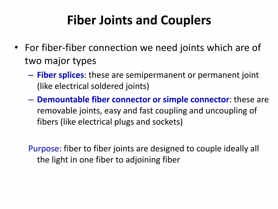
Fiber Joints and Couplers
• For fiber-fiber connection we need joints which are of two major types
– Fiber splices: these are semipermanent or permanent joint (like electrical soldered joints)
– Demountable fiber connector or simple connector: these are removable joints, easy and fast coupling and uncoupling of fibers (like electrical plugs and sockets)
Purpose: fiber to fiber joints are designed to couple ideally all the light in one fiber to adjoining fiber
Why Fiber Joints and Couplers are necessary?
• Optical fiber links require connection in order to make long fiber
• or for fiber coupling to sources or amplifier or termination to receiver
The number of intermediate fiber connections or joints depends on link length between repeaters
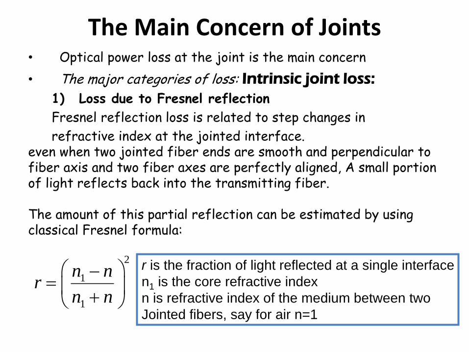
The Main Concern of Joints • Optical power loss at the joint is the main concern
• The major categories of loss: Intrinsic joint loss:
1) Loss due to Fresnel reflection
Fresnel reflection loss is related to step changes in
refractive index at the jointed interface. even when two jointed fiber ends are smooth and perpendicular to fiber axis and two fiber axes are perfectly aligned, A small portion of light reflects back into the transmitting fiber. The amount of this partial reflection can be estimated by using classical Fresnel formula:
2
1
1
n nr
n n
r is the fraction of light reflected at a single interface
n1 is the core refractive index
n is refractive index of the medium between two
Jointed fibers, say for air n=1
The loss due to Fresnel reflection at a single interface
The effect of Fresnel reflection at a fiber-fiber connection can be reduced by using an index-matching fluid between the gaps.
2. Loss due to deviations in the geometrical and optical parameters of the two jointed fibers. The problems may occur for (i) Different core and/or cladding diameters; (ii) Different NA and/or relative refractive index differences; (iii) Different refractive index profiles; (iv) Fiber faults: core ellipticity, core concentricity etc Use same fibers to keep this loss minimum
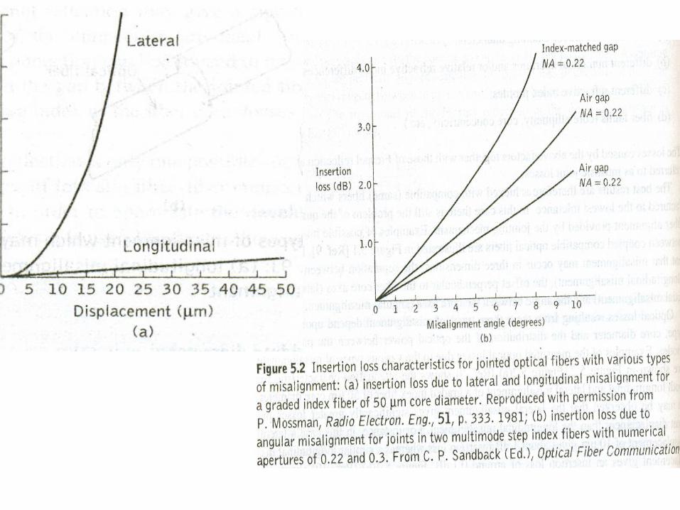
Loss due to misalignment A major source of loss at a fiber-fiber connection is caused by misalignment of two jointed fibers
1010log 1 dBFresLoss r
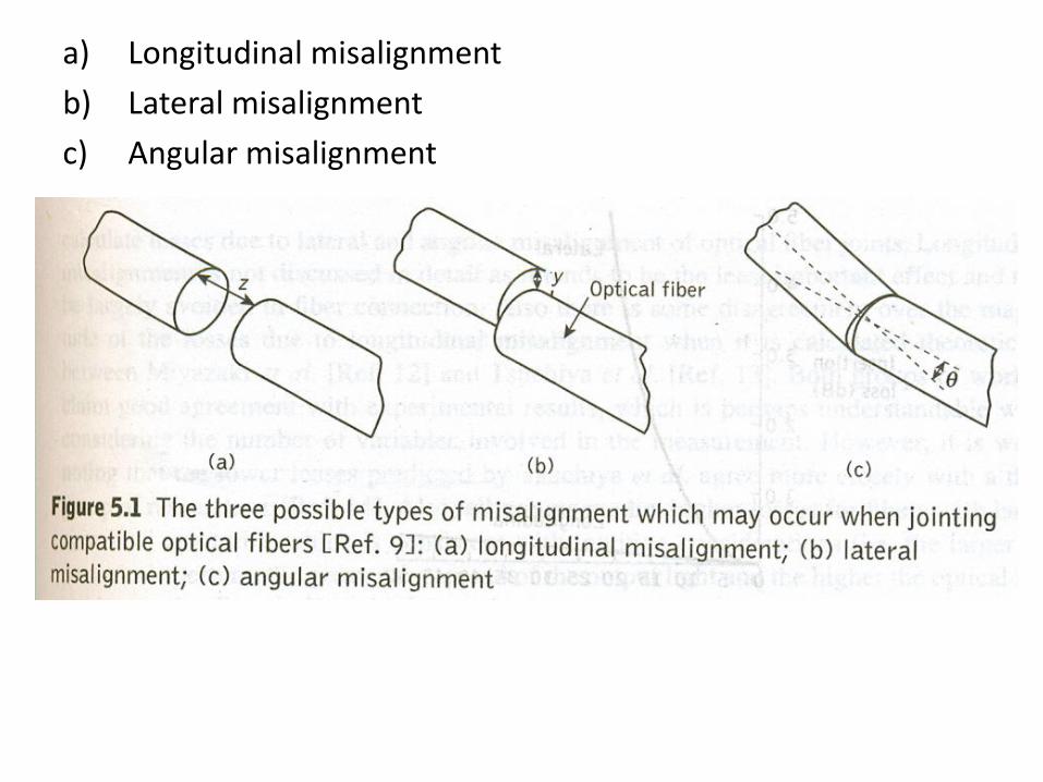
a) Longitudinal misalignment
b) Lateral misalignment
c) Angular misalignment
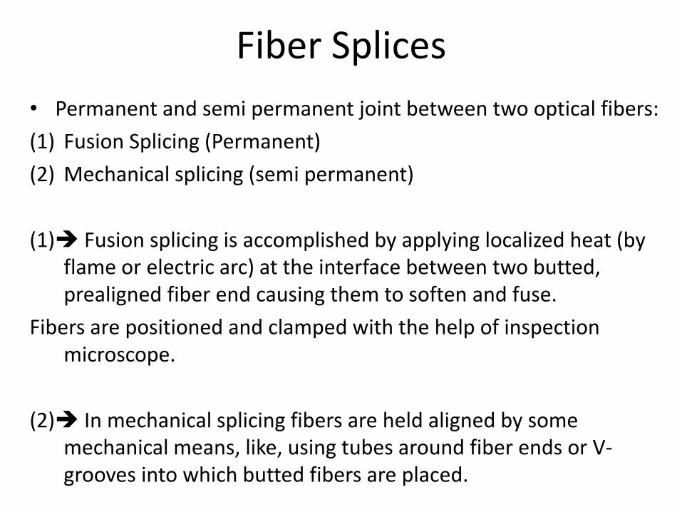
Fiber Splices
• Permanent and semi permanent joint between two optical fibers:
(1) Fusion Splicing (Permanent)
(2) Mechanical splicing (semi permanent)
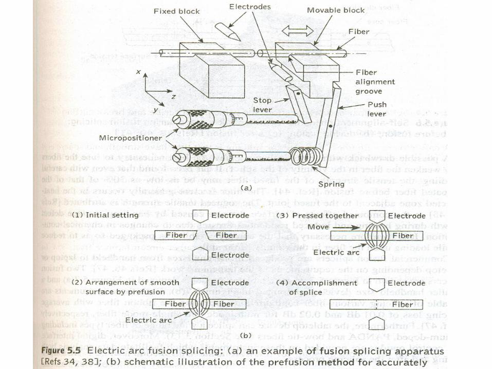
(1) Fusion splicing is accomplished by applying localized heat (by flame or electric arc) at the interface between two butted, prealigned fiber end causing them to soften and fuse.
Fibers are positioned and clamped with the help of inspection microscope.
(2) In mechanical splicing fibers are held aligned by some mechanical means, like, using tubes around fiber ends or V-grooves into which butted fibers are placed.
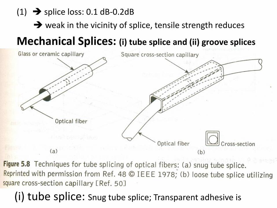
(1) splice loss: 0.1 dB-0.2dB
weak in the vicinity of splice, tensile strength reduces
Mechanical Splices: (i) tube splice and (ii) groove splices
(i) tube splice: Snug tube splice; Transparent adhesive is
Injected through a transverse bore in the capillary to give mechanical sealing and index matching of splice
• Insertion loss: 0.1 dB – 0.5 dB
• (ii) groove splices
In V-groove two fibers are jointed
V-groove splices are formed by sandwiching the butted fiber ends.
Insertion loss: 0.1 dB
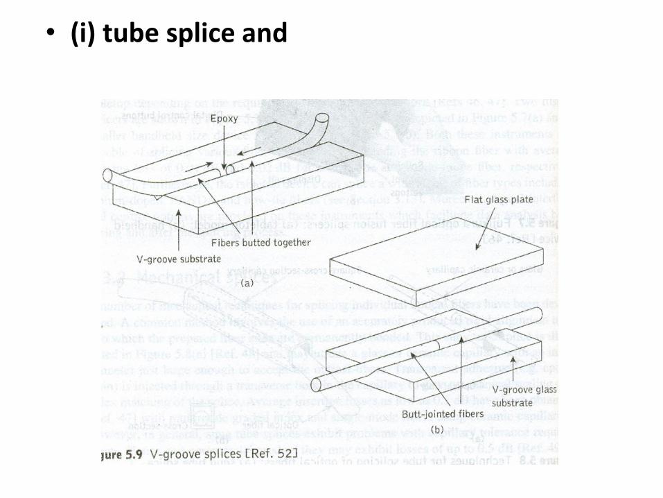
• (i) tube splice and
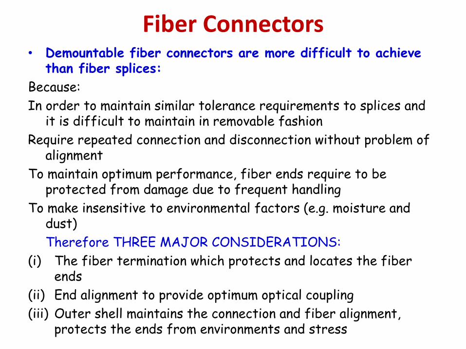
Fiber Connectors • Demountable fiber connectors are more difficult to achieve
than fiber splices:
Because:
In order to maintain similar tolerance requirements to splices and it is difficult to maintain in removable fashion
Require repeated connection and disconnection without problem of alignment
To maintain optimum performance, fiber ends require to be protected from damage due to frequent handling
To make insensitive to environmental factors (e.g. moisture and dust)
Therefore THREE MAJOR CONSIDERATIONS:
(i) The fiber termination which protects and locates the fiber ends
(ii) End alignment to provide optimum optical coupling
(iii) Outer shell maintains the connection and fiber alignment, protects the ends from environments and stress
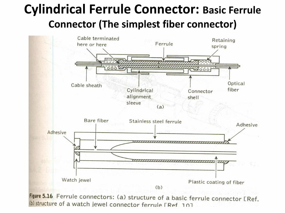
Cylindrical Ferrule Connector: Basic Ferrule
Connector (The simplest fiber connector)
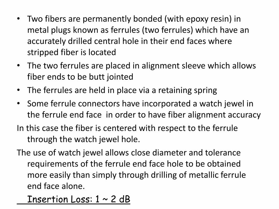
• Two fibers are permanently bonded (with epoxy resin) in metal plugs known as ferrules (two ferrules) which have an accurately drilled central hole in their end faces where stripped fiber is located
• The two ferrules are placed in alignment sleeve which allows fiber ends to be butt jointed
• The ferrules are held in place via a retaining spring
• Some ferrule connectors have incorporated a watch jewel in the ferrule end face in order to have fiber alignment accuracy
In this case the fiber is centered with respect to the ferrule through the watch jewel hole.
The use of watch jewel allows close diameter and tolerance requirements of the ferrule end face hole to be obtained more easily than simply through drilling of metallic ferrule end face alone.
Insertion Loss: 1 ~ 2 dB
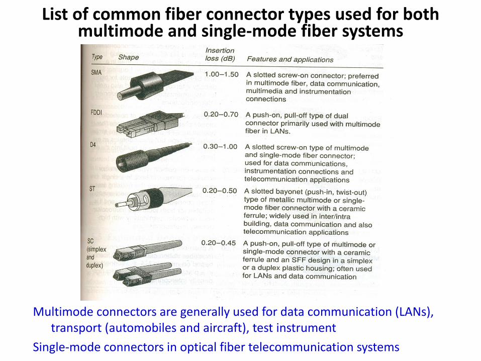
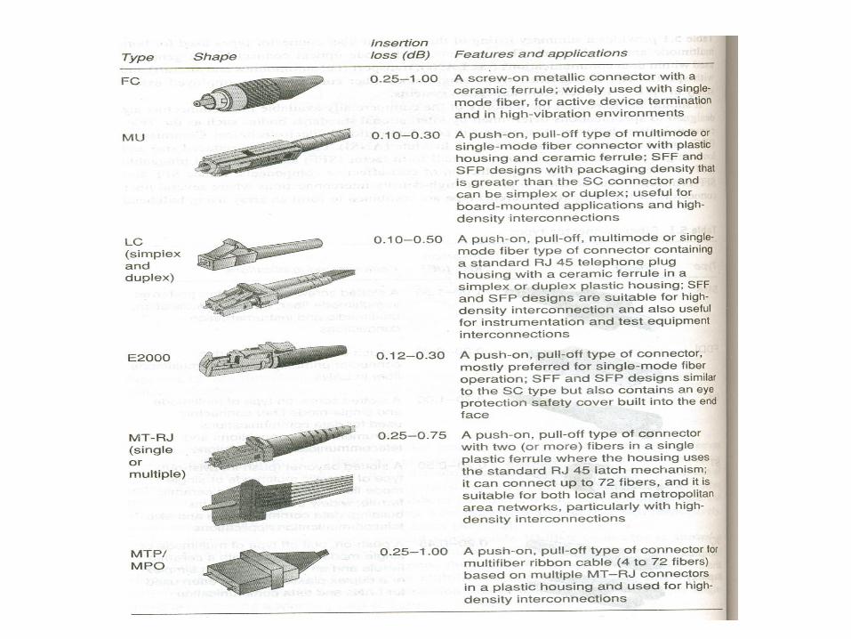
List of common fiber connector types used for both multimode and single-mode fiber systems
Multimode connectors are generally used for data communication (LANs), transport (automobiles and aircraft), test instrument
Single-mode connectors in optical fiber telecommunication systems
Fiber Couplers Fiber Couplers are branching devices that split all the light from a
main fiber into two or more fibers
Or Alternately couple a proportion of light propagating in the main fiber into a branch fiber
they can combine light from two or more branch fibers into a main fiber
Optical fiber couplers are passive devices in which power transfer takes place in two ways:
(i) Core-interaction type: through fiber core cross-section by butt jointing the fibers
(ii) Surface-interaction type: through fiber surface and normal to its axis by converting the guided core modes to both cladding and refracted modes
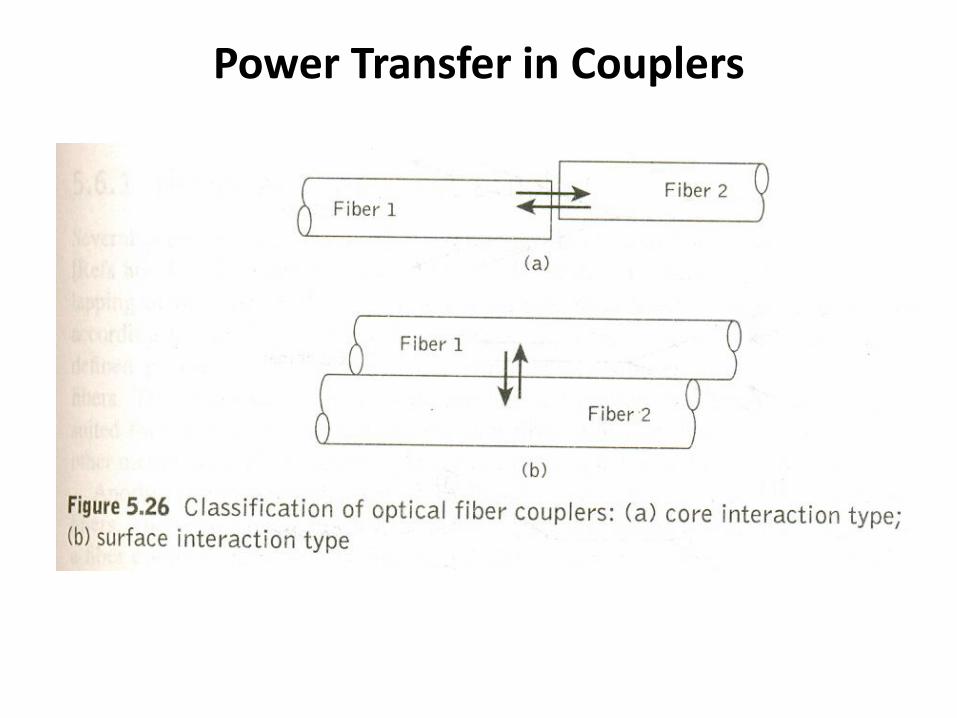
Power Transfer in Couplers
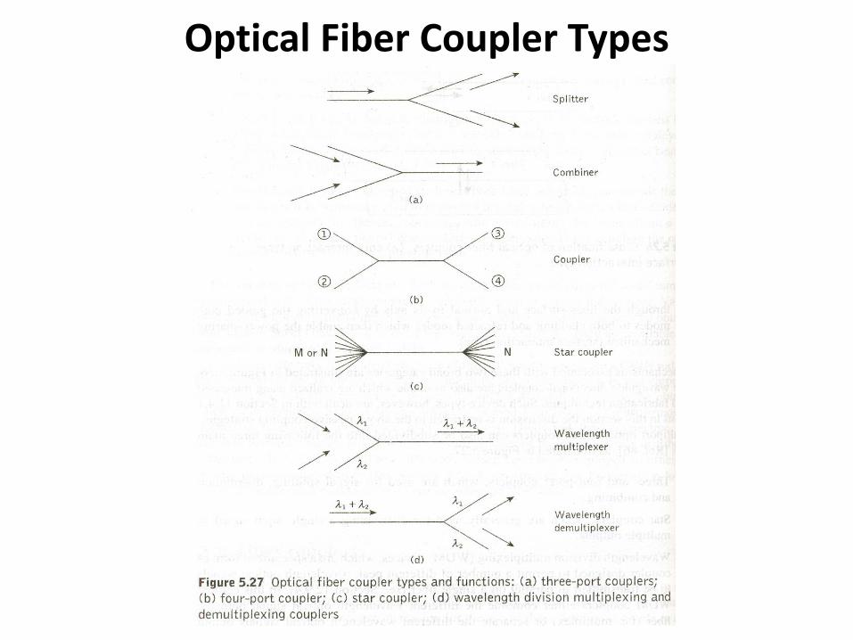
Optical Fiber Coupler Types
Functions of Multiport Couplers
(1) Three and four-port couplers: For signal splitting, distribution and combining
(2) Star Couplers: for distributing a single input signal to multiple outputs
(3) WDM devices: are specialized couplers designed to permit a number of different wavelength channels to be transmitted in parallel in a single fiber
WDM MUX: combine/multiplex different wavelength channels onto a fiber
WDM DeMux: separate different wavelength channels output from a fiber
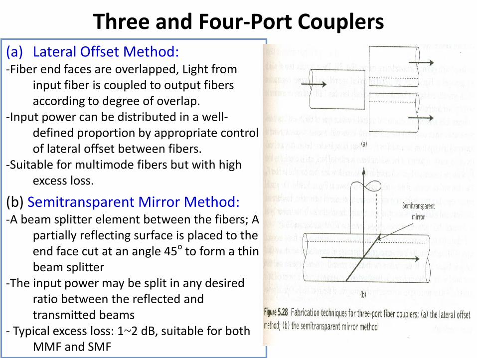
Three and Four-Port Couplers (a) Lateral Offset Method: -Fiber end faces are overlapped, Light from
input fiber is coupled to output fibers according to degree of overlap.
-Input power can be distributed in a well-defined proportion by appropriate control of lateral offset between fibers.
-Suitable for multimode fibers but with high excess loss.
(b) Semitransparent Mirror Method: -A beam splitter element between the fibers; A
partially reflecting surface is placed to the end face cut at an angle 45o to form a thin beam splitter
-The input power may be split in any desired ratio between the reflected and transmitted beams
- Typical excess loss: 1~2 dB, suitable for both MMF and SMF
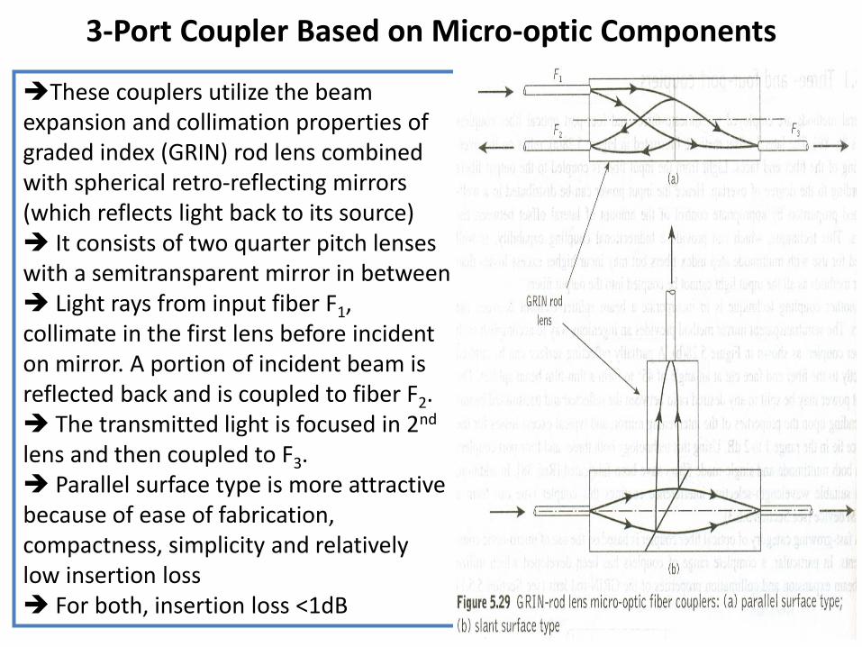
3-Port Coupler Based on Micro-optic Components
These couplers utilize the beam expansion and collimation properties of graded index (GRIN) rod lens combined with spherical retro-reflecting mirrors (which reflects light back to its source) It consists of two quarter pitch lenses with a semitransparent mirror in between Light rays from input fiber F1, collimate in the first lens before incident on mirror. A portion of incident beam is reflected back and is coupled to fiber F2. The transmitted light is focused in 2nd lens and then coupled to F3. Parallel surface type is more attractive because of ease of fabrication, compactness, simplicity and relatively low insertion loss For both, insertion loss <1dB