04 Quick Configuration
102
Quick Configuration NetPerformer ® System Reference
-
Upload
marijuanne -
Category
Documents
-
view
229 -
download
0
Transcript of 04 Quick Configuration
7/23/2019 04 Quick Configuration
http://slidepdf.com/reader/full/04-quick-configuration 1/102
Quick ConfigurationNetPerformer ® System Reference

7/23/2019 04 Quick Configuration
http://slidepdf.com/reader/full/04-quick-configuration 2/102
COPYRIGHTS AND DISCLAIMERS
Published Date: March 2011
Document # 1597
This publication contains information proprietary and confidential to Memotec Inc. Any reproduction,disclosure or unauthorized use of this publication is expressly prohibited except as Memotec Inc. mayotherwise authorize in writing.
Memotec Inc. reserves the right to make changes without notice in product or component design as warranted by evolution in user needs or progress in engineering or manufacturing technology. Changes which affect theoperation of the unit will be documented in the next revision of the manual.
We have made every effort to ensure the accuracy of the information presented in our documentation.However, Memotec assumes no responsibility for the accuracy of the information published. Productdocumentation is subject to change without notice. Changes, if any, will be incorporated in new editions ofthese documents. Memotec may make improvements or changes in the products or programs described within
the documents at any time without notice. Mention of products or services not manufactured or sold byMemotec is for informational purposes only and constitutes neither an endorsement nor a recommendation forsuch products or services.
Memotec Inc. is a wholly owned subsidiary of Comtech EF Data Corp., and its parent company ComtechTelecommunications Corp (NASDAQ: CMTL).
AccessView, CXTool, CX-U Series, CX-UA Series, AbisXpress, NetPerformer, AccessGate, ACTView,SDM-8400, and the SDM-9000 series of products are either registered trademarks or trademarks of MemotecInc.in Canada, the United States of America, and in other countries.
Windows is a registered trademark of Microsoft Corporation in the United States and other countries.
Any other trademarks are the property of their respective companies.
Copyright © 2011 Memotec Inc.
Memotec Inc.7755 Henri Bourassa Blvd. WestMontreal, QuebecCanada H4S 1P7Tel.: (514) 738-4781FAX: (514) 738-4436www.memotec.com
7/23/2019 04 Quick Configuration
http://slidepdf.com/reader/full/04-quick-configuration 3/102
Memotec Inc.
Contents
Chapter 1: Overv iew . . . . . . . . . . . . . . . . . . . . . . . . . . . . . . . . . . . . . . . . . . . . . . . . . . . . . . . 1-1
1. 1 The Command Line Interface (CLI) Tree. . . . . . . . . . . . . . . . . . . . . . . . . . 1-2
Chapter 2: WAN Con fig urat ion and Validation . . . . . . . . . . . . . . . . . . . . . . . . . . . . . . . . . . 2-1
2. 1 Configuring a Dedicated WAN Link . . . . . . . . . . . . . . . . . . . . . . . . . . . . . . 2-2
2.1.1 Built-in Serial Port . . . . . . . . . . . . . . . . . . . . . . . . . . . . . . . . . . . 2-22.1.2 Dual Serial Interface Card . . . . . . . . . . . . . . . . . . . . . . . . . . . . . 2-32.1.3 T1/E1 Channel . . . . . . . . . . . . . . . . . . . . . . . . . . . . . . . . . . . . . . 2-42.1.4 Displaying WAN Link Status . . . . . . . . . . . . . . . . . . . . . . . . . . . 2-42.1.5 Real-time Display of WAN Link Status . . . . . . . . . . . . . . . . . . . . 2-6
2. 2 Configuring a Backup Link. . . . . . . . . . . . . . . . . . . . . . . . . . . . . . . . . . . . . 2-7
2.2.1 Calling Side of the Backup Link . . . . . . . . . . . . . . . . . . . . . . . . . 2-72.2.2 Answering Side of the Backup Link . . . . . . . . . . . . . . . . . . . . . . 2-8
2. 3 Configuring a BOD Link. . . . . . . . . . . . . . . . . . . . . . . . . . . . . . . . . . . . . . 2-10
2.3.1 Calling Side of the BOD Link . . . . . . . . . . . . . . . . . . . . . . . . . . 2-102.3.2 Answering Side of the BOD Link . . . . . . . . . . . . . . . . . . . . . . . 2-11
2. 4 Configuring a WAN Link for Conditioned Activation . . . . . . . . . . . . . . . . 2-12
2. 5 Configuring a Frame Relay Connection. . . . . . . . . . . . . . . . . . . . . . . . . . 2-14
2.5.1 Configuring the Global Parameters . . . . . . . . . . . . . . . . . . . . . 2-142.5.2 Configuring the Physical Link. . . . . . . . . . . . . . . . . . . . . . . . . . 2-14
2.5.3 Built-in Serial Port . . . . . . . . . . . . . . . . . . . . . . . . . . . . . . . . . . 2-152.5.4 Dual Serial Interface Card . . . . . . . . . . . . . . . . . . . . . . . . . . . . 2-162.5.5 T1/E1 Channel . . . . . . . . . . . . . . . . . . . . . . . . . . . . . . . . . . . . . 2-172.5.6 Configuring the Logical Layer (PVCs) . . . . . . . . . . . . . . . . . . . 2-182.5.7 PVCR over Frame Relay . . . . . . . . . . . . . . . . . . . . . . . . . . . . . 2-192.5.8 RFC1490 . . . . . . . . . . . . . . . . . . . . . . . . . . . . . . . . . . . . . . . . . 2-202.5.9 Transparent (TRANSP) . . . . . . . . . . . . . . . . . . . . . . . . . . . . . . 2-212.5.10 MULTIPLEX . . . . . . . . . . . . . . . . . . . . . . . . . . . . . . . . . . . . . . . 2-232.5.11 Other PVC Types . . . . . . . . . . . . . . . . . . . . . . . . . . . . . . . . . . . 2-242.5.12 Displaying WAN/Frame Relay Link Status . . . . . . . . . . . . . . . . 2-24
2.5.13 Real-time Display of PVC DLCI Status . . . . . . . . . . . . . . . . . . 2-262. 6 Configuring an IP Connection . . . . . . . . . . . . . . . . . . . . . . . . . . . . . . . . . 2-27
2.6.1 Configuring the Global Parameters . . . . . . . . . . . . . . . . . . . . . 2-282.6.2 Configuring the IP Parameters. . . . . . . . . . . . . . . . . . . . . . . . . 2-282.6.3 Configuring the Physical Link. . . . . . . . . . . . . . . . . . . . . . . . . . 2-302.6.4 Ethernet Port . . . . . . . . . . . . . . . . . . . . . . . . . . . . . . . . . . . . . . 2-31

7/23/2019 04 Quick Configuration
http://slidepdf.com/reader/full/04-quick-configuration 4/102
Memotec Inc.
2.6.5 Built-in Serial Port . . . . . . . . . . . . . . . . . . . . . . . . . . . . . . . . . . 2-322.6.6 Dual Serial Interface Card . . . . . . . . . . . . . . . . . . . . . . . . . . . . 2-342.6.7 T1/E1 Channel. . . . . . . . . . . . . . . . . . . . . . . . . . . . . . . . . . . . . 2-352.6.8 Configure the Logical Layer (PVCs) . . . . . . . . . . . . . . . . . . . . 2-362.6.9 Displaying LAN/WAN Link Status . . . . . . . . . . . . . . . . . . . . . . 2-37
Chapter 3: Country-sp ecif ic Factory Setup . . . . . . . . . . . . . . . . . . . . . . . . . . . . . . . . . . . . 3-1
3. 1 Applyign the Country Code . . . . . . . . . . . . . . . . . . . . . . . . . . . . . . . . . . . . 3-2
Chapter 4: Global Functio ns . . . . . . . . . . . . . . . . . . . . . . . . . . . . . . . . . . . . . . . . . . . . . . . . 4-1
4. 1 Checking System Status . . . . . . . . . . . . . . . . . . . . . . . . . . . . . . . . . . . . . . 4-2
4.1.1 Displaying Hardware Information. . . . . . . . . . . . . . . . . . . . . . . . 4-24.1.2 Displaying Hardware Status . . . . . . . . . . . . . . . . . . . . . . . . . . . 4-34.1.3 Displaying Firmware Information . . . . . . . . . . . . . . . . . . . . . . . . 4-34.1.4 Displaying Channel Status. . . . . . . . . . . . . . . . . . . . . . . . . . . . . 4-4
4.1.5 Displaying Compression Dictionary Status . . . . . . . . . . . . . . . . 4-6
4. 2 Displaying and Setting the System Time. . . . . . . . . . . . . . . . . . . . . . . . . . 4-7
4.2.1 Displaying the Time . . . . . . . . . . . . . . . . . . . . . . . . . . . . . . . . . . 4-74.2.2 Setting the Time. . . . . . . . . . . . . . . . . . . . . . . . . . . . . . . . . . . . . 4-7
4. 3 Setting the Global Configuration Parameters . . . . . . . . . . . . . . . . . . . . . . 4-9
4.3.1 Generic Global Parameters . . . . . . . . . . . . . . . . . . . . . . . . . . . 4-104.3.2 Protocol-related Parameters . . . . . . . . . . . . . . . . . . . . . . . . . . 4-104.3.3 Setting the Unit Name . . . . . . . . . . . . . . . . . . . . . . . . . . . . . . . 4-114.3.4 Setting the Unit Routing Version . . . . . . . . . . . . . . . . . . . . . . . 4-12
Chapter 5: SE/GLOBAL Config uration Parameters . . . . . . . . . . . . . . . . . . . . . . . . . . . . . . 5-1
5. 1 About the GLOBAL submenu . . . . . . . . . . . . . . . . . . . . . . . . . . . . . . . . . . 5-2
5. 2 Standalone Base Product . . . . . . . . . . . . . . . . . . . . . . . . . . . . . . . . . . . . . 5-3
5.2.1 Unit name . . . . . . . . . . . . . . . . . . . . . . . . . . . . . . . . . . . . . . . . . 5-45.2.2 Unit routing version . . . . . . . . . . . . . . . . . . . . . . . . . . . . . . . . . . 5-45.2.3 Contact name . . . . . . . . . . . . . . . . . . . . . . . . . . . . . . . . . . . . . . 5-55.2.4 Unit location. . . . . . . . . . . . . . . . . . . . . . . . . . . . . . . . . . . . . . . . 5-55.2.5 Loopback . . . . . . . . . . . . . . . . . . . . . . . . . . . . . . . . . . . . . . . . . . 5-55.2.6 Link timeout delay . . . . . . . . . . . . . . . . . . . . . . . . . . . . . . . . . . . 5-55.2.7 Transit delay (s). . . . . . . . . . . . . . . . . . . . . . . . . . . . . . . . . . . . . 5-65.2.8 Daylight saving time. . . . . . . . . . . . . . . . . . . . . . . . . . . . . . . . . . 5-65.2.9 Default IP address . . . . . . . . . . . . . . . . . . . . . . . . . . . . . . . . . . . 5-65.2.10 Default IP mask (number of bits) . . . . . . . . . . . . . . . . . . . . . . . . 5-75.2.11 Default gateway . . . . . . . . . . . . . . . . . . . . . . . . . . . . . . . . . . . . . 5-85.2.12 SNMP trap: IP address 1,2,3,4 . . . . . . . . . . . . . . . . . . . . . . . . . 5-8
7/23/2019 04 Quick Configuration
http://slidepdf.com/reader/full/04-quick-configuration 5/102
Memotec Inc.
5.2.13 Frame relay status change trap . . . . . . . . . . . . . . . . . . . . . . . . . 5-95.2.14 Watch power supplies and fans . . . . . . . . . . . . . . . . . . . . . . . . . 5-95.2.15 Local unit DLCI address . . . . . . . . . . . . . . . . . . . . . . . . . . . . . . 5-105.2.16 Extension number (no. of digits) . . . . . . . . . . . . . . . . . . . . . . . 5-115.2.17 Country code . . . . . . . . . . . . . . . . . . . . . . . . . . . . . . . . . . . . . . 5-11
5.2.18 Jitter buffer (ms) . . . . . . . . . . . . . . . . . . . . . . . . . . . . . . . . . . . . 5-115.2.19 Enable voice/fax log . . . . . . . . . . . . . . . . . . . . . . . . . . . . . . . . . 5-125.2.20 Dial timer (s). . . . . . . . . . . . . . . . . . . . . . . . . . . . . . . . . . . . . . . 5-125.2.21 High priority voice class . . . . . . . . . . . . . . . . . . . . . . . . . . . . . . 5-135.2.22 Voice class . . . . . . . . . . . . . . . . . . . . . . . . . . . . . . . . . . . . . . . . 5-135.2.23 Global CIR for FR over IP . . . . . . . . . . . . . . . . . . . . . . . . . . . . 5-145.2.24 Timer in ms for FR over IP . . . . . . . . . . . . . . . . . . . . . . . . . . . . 5-145.2.25 Max number of voice channels over IP . . . . . . . . . . . . . . . . . . 5-145.2.26 Delay generated by a comma (ms) . . . . . . . . . . . . . . . . . . . . . 5-155.2.27 ISDN G4 Fax PCM switching enable . . . . . . . . . . . . . . . . . . . . 5-15
5.2.28 Auto save configuration delay (s) . . . . . . . . . . . . . . . . . . . . . . . 5-155.2.29 Enable VTR (Voice Traffic Routing) . . . . . . . . . . . . . . . . . . . . . 5-165.2.30 Enable Domain Dialing. . . . . . . . . . . . . . . . . . . . . . . . . . . . . . . 5-165.2.31 Enable hunt forwarding . . . . . . . . . . . . . . . . . . . . . . . . . . . . . . 5-175.2.32 Enable user access logging . . . . . . . . . . . . . . . . . . . . . . . . . . . 5-175.2.33 Exclusive access to console . . . . . . . . . . . . . . . . . . . . . . . . . . 5-17
5. 3 Rackmount Chassis. . . . . . . . . . . . . . . . . . . . . . . . . . . . . . . . . . . . . . . . . 5-18
5.3.1 Rack ID . . . . . . . . . . . . . . . . . . . . . . . . . . . . . . . . . . . . . . . . . . 5-185.3.2 RIP version for backplane links . . . . . . . . . . . . . . . . . . . . . . . . 5-195.3.3 IPX RIP for backplane links . . . . . . . . . . . . . . . . . . . . . . . . . . . 5-20
5.3.4 IP SAP for backplane links. . . . . . . . . . . . . . . . . . . . . . . . . . . . 5-205.3.5 OSPF for backplane links. . . . . . . . . . . . . . . . . . . . . . . . . . . . . 5-20
5. 4 SIP VoIP Option. . . . . . . . . . . . . . . . . . . . . . . . . . . . . . . . . . . . . . . . . . . . 5-21
5. 5 ATM Option . . . . . . . . . . . . . . . . . . . . . . . . . . . . . . . . . . . . . . . . . . . . . . . 5-21
Chapter 6: Controll ing Access to the NetPerformer . . . . . . . . . . . . . . . . . . . . . . . . . . . . . 6-1
6. 1 About Access Control . . . . . . . . . . . . . . . . . . . . . . . . . . . . . . . . . . . . . . . . 6-2
6. 2 Defining the User Profiles . . . . . . . . . . . . . . . . . . . . . . . . . . . . . . . . . . . . . 6-3
6.2.1 MONITOR Access Command Set . . . . . . . . . . . . . . . . . . . . . . . 6-4
6.2.2 Monitoring User Access . . . . . . . . . . . . . . . . . . . . . . . . . . . . . . . 6-56.2.3 Changing a Password . . . . . . . . . . . . . . . . . . . . . . . . . . . . . . . . 6-66.2.4 Removing Login Authorization . . . . . . . . . . . . . . . . . . . . . . . . . . 6-6
6. 3 Restricting FTP Access . . . . . . . . . . . . . . . . . . . . . . . . . . . . . . . . . . . . . . . 6-7
6. 4 Restricting Telnet Access . . . . . . . . . . . . . . . . . . . . . . . . . . . . . . . . . . . . . 6-9

7/23/2019 04 Quick Configuration
http://slidepdf.com/reader/full/04-quick-configuration 6/102
Memotec Inc.
6. 5 Authentication Using RADIUS. . . . . . . . . . . . . . . . . . . . . . . . . . . . . . . . . 6-11
6.5.1 Attributes Supported . . . . . . . . . . . . . . . . . . . . . . . . . . . . . . . . 6-116.5.2 Login Procedure . . . . . . . . . . . . . . . . . . . . . . . . . . . . . . . . . . . 6-116.5.3 Configuring the NetPerformer for RADIUS Authentication . . . 6-136.5.4 Example of Console Access . . . . . . . . . . . . . . . . . . . . . . . . . . 6-14
6.5.5 Example of Telnet Access . . . . . . . . . . . . . . . . . . . . . . . . . . . . 6-14
Index . . . . . . . . . . . . . . . . . . . . . . . . . . . . . . . . . . . . . . . . . . . . . . . . . . . . . . . . . . . . . . . Index-1

7/23/2019 04 Quick Configuration
http://slidepdf.com/reader/full/04-quick-configuration 7/102
1
Memotec Inc. 1-1
Overview

7/23/2019 04 Quick Configuration
http://slidepdf.com/reader/full/04-quick-configuration 8/102
Quick Configuration
1-2 Memotec Inc.
1.1 The Command Line Interface (CLI) Tree
NOTE: Complete information regarding the NetPerformer user interface, the CLItree, how to use the console, SNMP and/or text-based configuration to config-
ure the unit, single-line command entry and an overview of console com-mands is provided in the Getting Started module of this document series.
All NetPerformer console commands are accessed from the command line prompt, whichindicates the Unit ID .
• Assistance ( HE, ? ): For assistance in selecting a command or parameter value
• Configuration ( SETUP ): To configure the unit
• Display Information ( Dxy z and others): To monitor the unit
• Other:
- Configuration Maintenance
- System File Maintenance
- Fine Tuning
- Access and Redundancy
- Capture and Tests.
For further information on this grouping of console commands, refer to the chapterOverview of Console Commands in the Getting Started module of this documentseries.
Figure 1-1: Top Levels of the CLI Tree
7/23/2019 04 Quick Configuration
http://slidepdf.com/reader/full/04-quick-configuration 9/102
2
Memotec Inc. 2-1
WAN Configuration and Validation

7/23/2019 04 Quick Configuration
http://slidepdf.com/reader/full/04-quick-configuration 10/102
Quick Configuration
2-2 Memotec Inc.
2.1 Configuring a Dedicated WAN LinkA dedicated WAN link creates a leased-line connection between two NetPerformer units.Each unit requires a serial port or T1/E1 channel configured with the PVCR protocol.
A dedicated WAN link is configured with the PORT or SLOT submenu of the SETUP command.
2.1.1 Buil t-in Ser ial Por t
To configure a built-in serial port as a dedicated WAN link:
1. Enter the menu sequence: SE PORT
2. Select the Port number
3. Set the Protocol to PVCR
4. Set the Mode to DEDICATED
Figure 2-1: Dedicated WAN Link Scenario
Figure 2-2: SETUP/PORT and SETUP/SLOT/CHANNEL Paths on the CLI Tree for PVCR Protocol
7/23/2019 04 Quick Configuration
http://slidepdf.com/reader/full/04-quick-configuration 11/102
WAN Configuration and Validation
Memotec Inc. 2-3
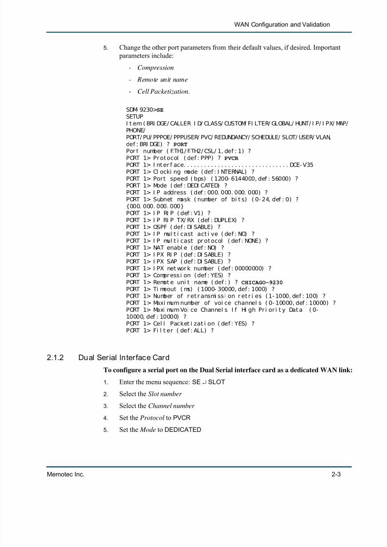
5. Change the other port parameters from their default values, if desired. Important parameters include:
- Compression
- Remote unit name
- Cell Packetization .
SDM- 9230> SESETUPI t em ( BRI DGE/ CALLER I D/ CLASS/ CUSTOM/ FI LTER/ GLOBAL/ HUNT/ I P/ I PX/ MAP/PHONE/PORT/ PU/ PPPOE/ PPPUSER/ PVC/ REDUNDANCY/ SCHEDULE/ SLOT/ USER/ VLAN,def : BRI DGE) ? PORTPor t number ( ETH1/ ETH2/ CSL/ 1, def : 1) ?PORT 1> Pr ot ocol ( def : PPP) ? PVCR PORT 1> I nt er f ace. . . . . . . . . . . . . . . . . . . . . . . . . . . . . . . DCE- V35PORT 1> Cl ocki ng mode ( def : I NTERNAL) ?PORT 1> Por t speed ( bps) ( 1200- 6144000, def : 56000) ?PORT 1> Mode ( def : DEDI CATED) ?PORT 1> I P address ( def : 000. 000. 000. 000) ?PORT 1> Subnet mask ( number of bi t s) ( 0- 24, def : 0) ?{000. 000. 000. 000}PORT 1> I P RI P ( def : V1) ?PORT 1> I P RI P TX/ RX ( def : DUPLEX) ?PORT 1> OSPF ( def : DI SABLE) ?PORT 1> I P mul t i cast act i ve ( def : NO) ?PORT 1> I P mul t i cast pr ot ocol ( def : NONE) ?PORT 1> NAT enabl e ( def : NO) ?PORT 1> I PX RI P ( def : DI SABLE) ?PORT 1> I PX SAP ( def : DI SABLE) ?PORT 1> I PX net wor k number ( def : 00000000) ?PORT 1> Compr ess i on ( def : YES) ?PORT 1> Remot e uni t name ( def : ) ? CHICAGO-9230
PORT 1> Ti meout ( ms) ( 1000- 30000, def : 1000) ?PORT 1> Number of r et r ansmi ss i on r et r i es ( 1- 1000, def : 100) ?PORT 1> Maxi mum number of voi ce channel s ( 0- 10000, def : 10000) ?PORT 1> Maxi mum Voi ce Channel s I f Hi gh Pr i or i t y Dat a ( 0-10000, def : 10000) ?PORT 1> Cel l Packet i zat i on ( def : YES) ?PORT 1> Fi l t er ( def : ALL) ?
2.1.2 Dual Serial Interface Card
To configure a serial port on the Dual Serial interface card as a dedicated WAN link:
1. Enter the menu sequence: SE SLOT2. Select the Slot number
3. Select the Channel number
4. Set the Protocol to PVCR
5. Set the Mode to DEDICATED

7/23/2019 04 Quick Configuration
http://slidepdf.com/reader/full/04-quick-configuration 12/102
Quick Configuration
2-4 Memotec Inc.
6. Change the other port parameters from their default values, if desired. Important parameters are as for a built-in serial port.
2.1.3 T1/E1 Channel
To configure a T1/E1 channel as a dedicated WAN link:
1. Enter the menu sequence: SE SLOT
2. Select the Slot number
3. Enter CHANNEL at the Item prompt
4. Select the Channel number , e.g. 102 , where the first digit indicates the slot and thelast two digits indicate the channel
5. Set the Protocol to PVCR
6. Set the Mode to DEDICATED
7. Change the other port parameters from their default values, if desired. Important
parameters are as for a built-in serial port.For details on configuring a dedicated WAN link, refer to “Configuring a Dedicated WANLink” on page 2-2 of the NetPerformer Configuration Reference Manual.
2.1.4 Displaying WAN Link Status
• To view the current PowerCell routing table , use the Display Destination Table(DD) command.
• For a continuous display of WAN link status in real time , use the Display PortStates ( DPORT ) command.
Displaying the PowerCell Routing TableTo view the routing table of all NetPerformer PowerCell destinations:
• Enter DD at the main command prompt.
The table shows all destinations that can be reached via ports, channels and PVCsconfigured with the PVCR protocol.
Figure 2-3: DD and DPORT Paths on the CLI Tree

7/23/2019 04 Quick Configuration
http://slidepdf.com/reader/full/04-quick-configuration 13/102
WAN Configuration and Validation
Memotec Inc. 2-5
SDM- 9230> DDDI SPLAY DESTI NATI ON TABLE
The dest i nat i on t abl e has 13 ent r y( i es)
DESTI NATI ON VAL COST I NTRF NEXT HOP AGE
ATM1 Y 1 PVC 7 ATM1. 80- 1 19 dATM1. 80- 1 Y 0 PVC 7 SDM- 9230 0 sATM2 Y 1 PVC 8 ATM2. 60- 1 58 sATM2. 60- 1 Y 0 PVC 8 SDM- 9230 0 sFR. 60- 1 Y 1 PVC 2 FR. 60- 3 19 dFR. 60- 2 Y 2 PVC 2 FR. 60- 3 19 dFR. 60- 3 Y 0 PVC 2 SDM- 9230 0 sFR. 60- 4 Y 1 PVC 2 FR. 60- 3 19 dSDM- 9230 Y 0 LOCAL SDM- 9230 0 sSDM- 9230- 1 Y 1 PVC 1 SDM- 9230- 2 19 dSDM- 9230- 2 Y 0 PVC 1 SDM- 9230 0 sSDM- 9230- 3 Y 1 PVC 1 SDM- 9230- 2 19 dI SDN Y 2 PVC 7 ATM1. 80- 1 19 d

7/23/2019 04 Quick Configuration
http://slidepdf.com/reader/full/04-quick-configuration 14/102
Quick Configuration
2-6 Memotec Inc.
2.1.5 Real-time Display of WAN Link Status
To view the current status of all WAN links in real time:
1. Enter DPORT at the main command prompt
2. Navigate the display using the <Home> , <End> , <Up Arro w> and <Down Arro w> keys
The various statistics in the DPORT display are updated dynamically andcontinuously refreshed on the screen.
3. To quit from the DPORT screen, press any key other than the navigation keys.
SDM- 9230> DPORTDI SPLAY PORT STATES- - - - - - - - - - - - - - - - - - - - - - - - - - - - - - - - - - - - - - - - - - - - - - - - - - - - - - - - - - - - - - - - - - - - - - - - - - -- - - - -| PORT# PROTOCOL I NTERFACE SPEED MODEM STATE DELAY|| ( BPS) SI GNALS |- - - - - - - - - - - - - - - - - - - - - - - - - - - - - - - - - - - - - - - - - - - - - - - - - - - - - - - - - - - - - - - - - - - - - - - - - - -
- - - - -| 1 FR- USER DTE- V35 2048k STDRC- DATA|| 101 ATM T1- TE 1536k STDRC- DATA || || || || || || || || || || || |
| || || || || || Modems i gnal s : d(S ) r d( T) r (D)cd (R) t s ( C) t s r ( I ) ( - ) o f f|- - Use HOME, END, UP and DOWN ar r ow keys t o scr ol l . Pr ess any ot her key t oexi t . -

7/23/2019 04 Quick Configuration
http://slidepdf.com/reader/full/04-quick-configuration 15/102
7/23/2019 04 Quick Configuration
http://slidepdf.com/reader/full/04-quick-configuration 16/102
Quick Configuration
2-8 Memotec Inc.
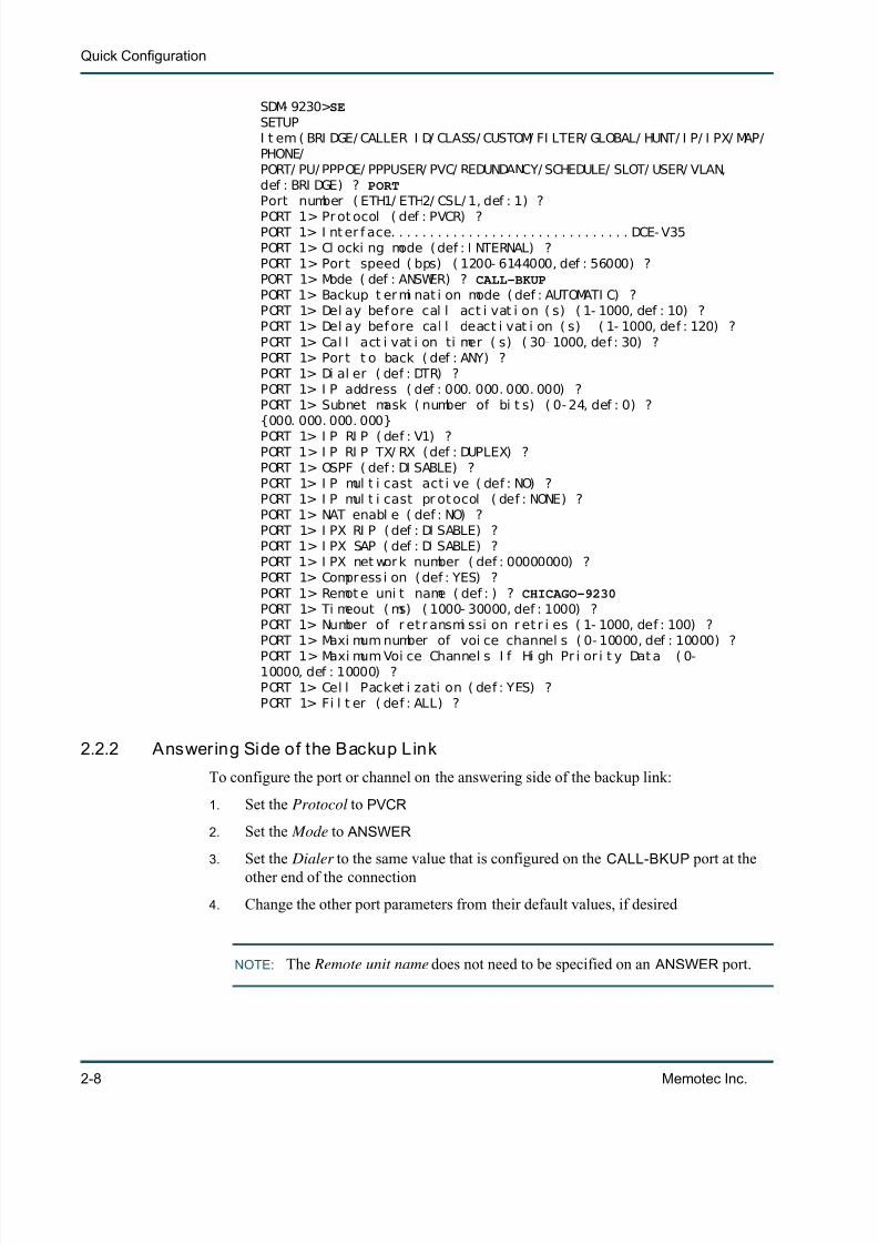
SDM- 9230> SESETUPI t em ( BRI DGE/ CALLER I D/ CLASS/ CUSTOM/ FI LTER/ GLOBAL/ HUNT/ I P/ I PX/ MAP/PHONE/PORT/ PU/ PPPOE/ PPPUSER/ PVC/ REDUNDANCY/ SCHEDULE/ SLOT/ USER/ VLAN,def : BRI DGE) ? PORTPort number ( ETH1/ ETH2/ CSL/ 1, def : 1) ?
PORT 1> Pr ot ocol ( def : PVCR) ?PORT 1> I nt er f ace. . . . . . . . . . . . . . . . . . . . . . . . . . . . . . . DCE- V35PORT 1> Cl ocki ng mode ( def : I NTERNAL) ?PORT 1> Por t speed ( bps) ( 1200- 6144000, def : 56000) ?PORT 1> Mode ( def : ANSWER) ? CALL-BKUPPORT 1> Backup t er mi nat i on mode ( def : AUTOMATI C) ?PORT 1> Del ay bef ore cal l act i vat i on ( s) ( 1- 1000, def : 10) ?PORT 1> Del ay bef ore cal l deact i vat i on ( s) ( 1- 1000, def : 120) ?PORT 1> Cal l act i vat i on ti mer ( s) ( 30- 1000, def : 30) ?PORT 1> Por t t o back ( def : ANY) ?PORT 1> Di al er ( def : DTR) ?PORT 1> I P address ( def : 000. 000. 000. 000) ?PORT 1> Subnet mask ( number of bi t s) ( 0- 24, def : 0) ?{000. 000. 000. 000}PORT 1> I P RI P ( def : V1) ?PORT 1> I P RI P TX/ RX (def : DUPLEX) ?PORT 1> OSPF ( def : DI SABLE) ?PORT 1> I P mul t i cast act i ve ( def : NO) ?PORT 1> I P mul t i cast pr ot ocol ( def : NONE) ?PORT 1> NAT enabl e ( def : NO) ?PORT 1> I PX RI P ( def : DI SABLE) ?PORT 1> I PX SAP ( def : DI SABLE) ?PORT 1> I PX net wor k number ( def : 00000000) ?PORT 1> Compress i on ( def : YES) ?PORT 1> Remot e uni t name ( def : ) ? CHICAGO-9230PORT 1> Ti meout ( ms) ( 1000- 30000, def : 1000) ?PORT 1> Number of r et r ansmi ssi on r et r i es ( 1- 1000, def : 100) ?PORT 1> Maxi mum number of voi ce channel s ( 0- 10000, def : 10000) ?PORT 1> Maxi mum Voi ce Channel s I f Hi gh Pr i or i t y Dat a ( 0-10000, def : 10000) ?PORT 1> Cel l Packet i zati on ( def : YES) ?PORT 1> Fi l t er ( def : ALL) ?
2.2.2 Answering Side of the Backup Link
To configure the port or channel on the answering side of the backup link:
1. Set the Protocol to PVCR
2. Set the Mode to ANSWER
3. Set the Dialer to the same value that is configured on the CALL-BKUP port at theother end of the connection
4. Change the other port parameters from their default values, if desired
NOTE: The Remote unit name does not need to be specified on an ANSWER port.

7/23/2019 04 Quick Configuration
http://slidepdf.com/reader/full/04-quick-configuration 17/102
WAN Configuration and Validation
Memotec Inc. 2-9
Not all types of T1/E1 channels can be configured as the answering side of a backupconnection. Refer to the section Limitations on Digital Channels in the Digital Data module of this document series .
SDM- 9230> SESETUPI t em ( BRI DGE/ CALLER I D/ CLASS/ CUSTOM/ FI LTER/ GLOBAL/ HUNT/ I P/ I PX/ MAP/
PHONE/PORT/ PU/ PPPOE/ PPPUSER/ PVC/ REDUNDANCY/ SCHEDULE/ SLOT/ USER/ VLAN,def : BRI DGE) ? PORTPor t number ( ETH1/ ETH2/ CSL/ 1, def : 1) ?PORT 1> Pr ot ocol ( def : PVCR) ?PORT 1> I nt er f ace. . . . . . . . . . . . . . . . . . . . . . . . . . . . . . . DCE- V35PORT 1> Cl ocki ng mode ( def : I NTERNAL) ?PORT 1> Por t speed ( bps) ( 1200- 6144000, def : 56000) ?PORT 1> Mode ( def : DEDI CATED) ? ANSWER PORT 1> Di al er ( def : DTR) ?PORT 1> I P address ( def : 000. 000. 000. 000) ?PORT 1> Subnet mask ( number of bi t s) ( 0- 24, def : 0) ?{000. 000. 000. 000}PORT 1> I P RI P ( def : V1) ?PORT 1> I P RI P TX/ RX ( def : DUPLEX) ?PORT 1> OSPF ( def : DI SABLE) ?PORT 1> I P mul t i cast act i ve ( def : NO) ?PORT 1> I P mul t i cast pr ot ocol ( def : NONE) ?PORT 1> NAT enabl e ( def : NO) ?PORT 1> I PX RI P ( def : DI SABLE) ?PORT 1> I PX SAP ( def : DI SABLE) ?PORT 1> I PX net wor k number ( def : 00000000) ?PORT 1> Compr ess i on ( def : YES) ?PORT 1> Remot e uni t name ( def : ) ? CHICAGO-9230PORT 1> Ti meout ( ms) ( 1000- 30000, def : 1000) ?PORT 1> Number of r et r ansmi ss i on r et r i es ( 1- 1000, def : 100) ?PORT 1> Maxi mum number of voi ce channel s ( 0- 10000, def : 10000) ?PORT 1> Maxi mum Voi ce Channel s I f Hi gh Pr i or i t y Dat a ( 0-10000, def : 10000) ?PORT 1> Cel l Packet i zat i on ( def : YES) ?PORT 1> Fi l t er ( def : ALL) ?
For details on configuring a backup link, refer to the section Configuring a Backup Link in the WAN/Leased Lines module of this document series.

7/23/2019 04 Quick Configuration
http://slidepdf.com/reader/full/04-quick-configuration 18/102
Quick Configuration
2-10 Memotec Inc.
2.3 Configuring a BOD LinkA Bandwidth On Demand (BOD) link creates an additional route when the bandwidth
provided by a dedicated WAN link is insufficient to meet current traffic demands.
• One side is configured to activate a call when traffic becomes heavy ( CALL-BOD
mode)• The other side is configured to answer the call ( ANSWER mode).
A BOD link is configured with the PORT or SLOT submenu of the SETUP command, inmuch the same way as for a dedicated WAN link (see Figure 2-2 ).
2.3.1 Calling Side of the BOD Link
To configure the port or channel on the calling side of the BOD link:
1. Set the Protocol to PVCR
2. Set the Mode to CALL-BOD
3. Specify which dedicated WAN link or links this port backs up, using the Port to back parameter
4. Set the Dialer to either DTR or X21-L1
Phone number dialing cannot be used to raise a BOD link .
5. Change the other port parameters from their default values, if desired. Important parameters include:
- Delay before BOD call activation (s)
- Delay before BOD call deactivation (s)
- BOD level (%) .
SDM- 9230> SESETUPI t em ( BRI DGE/ CALLER I D/ CLASS/ CUSTOM/ FI LTER/ GLOBAL/ HUNT/ I P/ I PX/ MAP/
PHONE/PORT/ PU/ PPPOE/ PPPUSER/ PVC/ REDUNDANCY/ SCHEDULE/ SLOT/ USER/ VLAN,def : BRI DGE) ? PORTPort number ( ETH1/ ETH2/ CSL/ 1, def : 1) ?PORT 1> Pr ot ocol ( def : PVCR) ?PORT 1> I nt er f ace. . . . . . . . . . . . . . . . . . . . . . . . . . . . . . . DCE- V35PORT 1> Cl ocki ng mode ( def : I NTERNAL) ?PORT 1> Por t speed ( bps) ( 1200- 6144000, def : 56000) ?
Figure 2-5: BOD Link Scenario
7/23/2019 04 Quick Configuration
http://slidepdf.com/reader/full/04-quick-configuration 19/102
WAN Configuration and Validation
Memotec Inc. 2-11
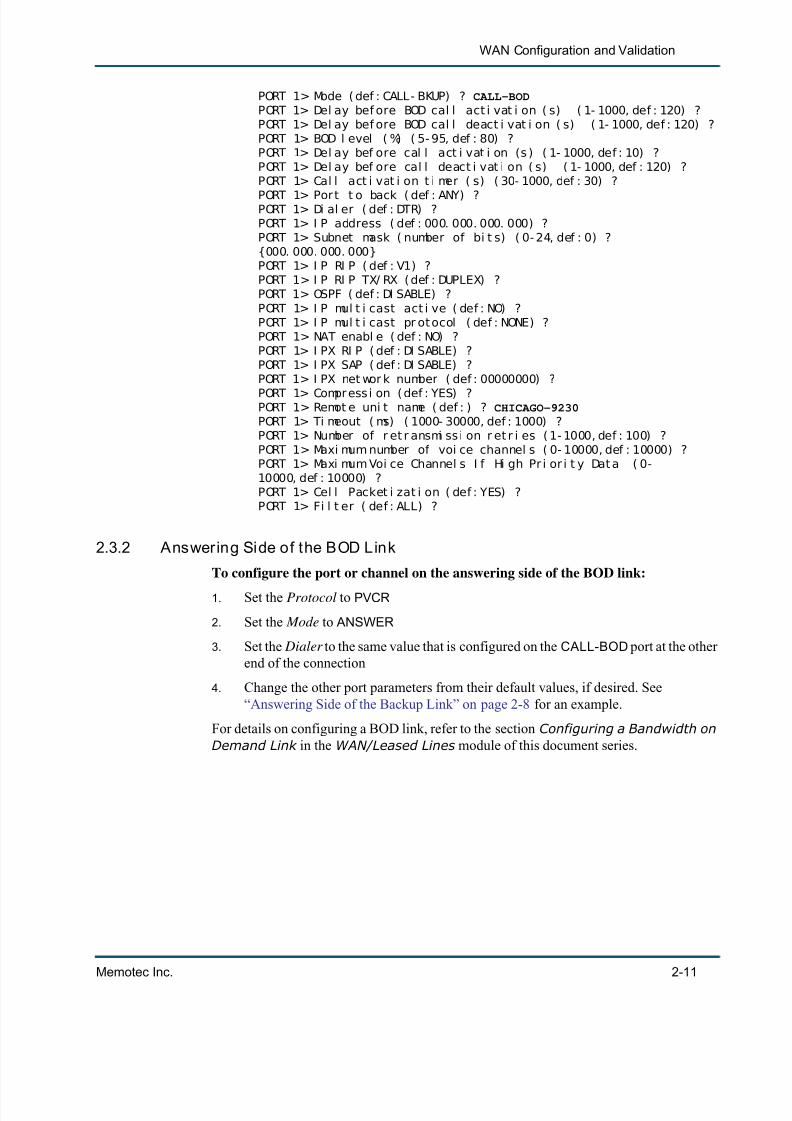
PORT 1> Mode ( def : CALL- BKUP) ? CALL-BODPORT 1> Del ay bef ore BOD cal l act i vat i on ( s) ( 1- 1000, def : 120) ?PORT 1> Del ay bef ore BOD cal l deact i vat i on ( s) ( 1- 1000, def : 120) ?PORT 1> BOD l evel ( %) ( 5- 95, def : 80) ?PORT 1> Del ay bef ore cal l act i vat i on (s ) ( 1- 1000, def : 10) ?PORT 1> Del ay bef ore cal l deact i vat i on ( s) ( 1- 1000, def : 120) ?PORT 1> Cal l act i vat i on t i mer ( s) ( 30- 1000, def : 30) ?
PORT 1> Por t t o back ( def : ANY) ?PORT 1> Di al er ( def : DTR) ?PORT 1> I P address ( def : 000. 000. 000. 000) ?PORT 1> Subnet mask ( number of bi t s) ( 0- 24, def : 0) ?{000. 000. 000. 000}PORT 1> I P RI P ( def : V1) ?PORT 1> I P RI P TX/ RX ( def : DUPLEX) ?PORT 1> OSPF ( def : DI SABLE) ?PORT 1> I P mul t i cast act i ve ( def : NO) ?PORT 1> I P mul t i cast pr ot ocol ( def : NONE) ?PORT 1> NAT enabl e ( def : NO) ?PORT 1> I PX RI P ( def : DI SABLE) ?PORT 1> I PX SAP ( def : DI SABLE) ?PORT 1> I PX net wor k number ( def : 00000000) ?PORT 1> Compr ess i on ( def : YES) ?PORT 1> Remot e uni t name ( def : ) ? CHICAGO-9230PORT 1> Ti meout ( ms) ( 1000- 30000, def : 1000) ?PORT 1> Number of r et r ansmi ss i on r et r i es ( 1- 1000, def : 100) ?PORT 1> Maxi mum number of voi ce channel s ( 0- 10000, def : 10000) ?PORT 1> Maxi mum Voi ce Channel s I f Hi gh Pr i or i t y Dat a ( 0-10000, def : 10000) ?PORT 1> Cel l Packet i zat i on ( def : YES) ?PORT 1> Fi l t er ( def : ALL) ?
2.3.2 Answering Side of the BOD Link
To configure the port or channel on the answering side of the BOD link:
1. Set the Protocol to PVCR
2. Set the Mode to ANSWER
3. Set the Dialer to the same value that is configured on the CALL-BOD port at the otherend of the connection
4. Change the other port parameters from their default values, if desired. See“Answering Side of the Backup Link” on page 2-8 for an example.
For details on configuring a BOD link, refer to the section Configuring a Bandwidth onDemand Link in the WAN/Leased Lines module of this document series.

7/23/2019 04 Quick Configuration
http://slidepdf.com/reader/full/04-quick-configuration 20/102
Quick Configuration
2-12 Memotec Inc.
2.4 Configuring a WAN Link for Conditioned ActivationWAN link activation can be conditioned by the presence of active modem signals on auser port that sends data via this link.
• The user port Protocol must be set to HDLC , DDCMP , T-ASYNC , R-ASYNC ,
BSC , COP or PASSTHRU• For a DCE connection, the DCD signal must be present.
• For a DTE connection, the DTR signal must be present.
Bring the link up by activating the modem signals on the attached user equipment.
• When the NetPerformer detects the modem signals, it immediately activates thelink required to transmit the data to its destination.
• When you deactivate the modem signals, the NetPerformer responds by discon-necting the link.
A conditioned link is configured with the PORT or SLOT submenu of the SETUP command, in much the same way as for a dedicated WAN link (see Figure 2-2 ).
To configure a port or channel as a conditioned link:
1. Set the Protocol to PVCR
2. Set the Mode to WAIT USER
3. Change the other port parameters from their default values, if desired. Important parameters include:
• Compression
• Remote unit name .
SDM- 9230> SESETUPI t em ( BRI DGE/ CALLER I D/ CLASS/ CUSTOM/ FI LTER/ GLOBAL/ HUNT/ I P/ I PX/ MAP/PHONE/PORT/ PU/ PPPOE/ PPPUSER/ PVC/ REDUNDANCY/ SCHEDULE/ SLOT/ USER/ VLAN,def : BRI DGE) ? PORTPort number ( ETH1/ ETH2/ CSL/ 1, def : 1) ?
Figure 2-6: Conditioned Link Scenario

7/23/2019 04 Quick Configuration
http://slidepdf.com/reader/full/04-quick-configuration 21/102
WAN Configuration and Validation
Memotec Inc. 2-13
PORT 1> Pr ot ocol ( def : PVCR) ?PORT 1> I nt er f ace. . . . . . . . . . . . . . . . . . . . . . . . . . . . . . . DCE- V35PORT 1> Cl ocki ng mode ( def : I NTERNAL) ?PORT 1> Por t speed ( bps) ( 1200- 6144000, def : 56000) ?PORT 1> Mode ( def : I NACTI VE) ? WAIT USER PORT 1> I P address ( def : 000. 000. 000. 000) ?PORT 1> Subnet mask ( number of bi t s) ( 0- 24, def : 0) ?
{000. 000. 000. 000}PORT 1> I P RI P ( def : V1) ?PORT 1> I P RI P TX/ RX ( def : DUPLEX) ?PORT 1> OSPF ( def : DI SABLE) ?PORT 1> I P mul t i cast act i ve ( def : NO) ?PORT 1> I P mul t i cast pr ot ocol ( def : NONE) ?PORT 1> NAT enabl e ( def : NO) ?PORT 1> I PX RI P ( def : DI SABLE) ?PORT 1> I PX SAP ( def : DI SABLE) ?PORT 1> I PX net wor k number ( def : 00000000) ?PORT 1> Compr ess i on ( def : YES) ?PORT 1> Remot e uni t name ( def : CHI CAGO- 9230) ?PORT 1> Ti meout ( ms) ( 1000- 30000, def : 1000) ?PORT 1> Number of r et r ansmi ss i on r et r i es ( 1- 1000, def : 100) ?PORT 1> Maxi mum number of voi ce channel s ( 0- 10000, def : 10000) ?PORT 1> Maxi mum Voi ce Channel s I f Hi gh Pr i or i t y Dat a ( 0-10000, def : 10000) ?PORT 1> Cel l Packet i zat i on ( def : YES) ?PORT 1> Fi l t er ( def : ALL) ?

7/23/2019 04 Quick Configuration
http://slidepdf.com/reader/full/04-quick-configuration 22/102
Quick Configuration
2-14 Memotec Inc.
2.5 Configuring a Frame Relay ConnectionTo set up a Frame Relay connection, you need to configure:
• Global parameters that affect Frame Relay operations (see next section)
• The physical link (see “Configuring the Physical Link” on page 2-14 )
• The logical layer, or PVCs (see “Configuring the Logical Layer (PVCs)” on page 2-18 ).
2.5.1 Configuring the Global Parameters
To configure the global parameters that affect Frame Relay operations:
1. Enter the menu sequence: SE GLOBAL
Refer to Figure 4-7 for the SETUP/GLOBAL path in the CLI tree.
2. Change the Frame Relay parameters from their default values, if desired:
- Frame relay status change trap- Local unit DLCI address
- Global CIR for FR over IP
- Timer in ms for FR over IP
For information concerning valid values for these parameters, consult the appen-dix “SE/GLOBAL Configuration Parameters” on page 5-1 .
2.5.2 Conf igur ing the Phys ical Link
The physical link provides WAN connectivity between a NetPerformer unit and the Frame
Relay cloud, or between a unit and an end-user device.• Each network connection requires a serial port or T1/E1 channel configured
with the FR-USER protocol
Figure 2-7: Basic Frame Relay Scenario

7/23/2019 04 Quick Configuration
http://slidepdf.com/reader/full/04-quick-configuration 23/102
WAN Configuration and Validation
Memotec Inc. 2-15
• Each end-user device connection requires a serial port or T1/E1 channel con-figured with the FR-NET protocol.
A Frame Relay link is configured with the PORT or SLOT submenu of the SETUP command.
2.5.3 Bui lt-in Serial Por t
To configure a built-in serial port as a Frame Relay link:
1. Enter the menu sequence: SE PORT
2. Select the Port number
3. Set the Protocol to FR-NET if the port connects to an end-user device
Set the protocol to FR-USER if the port connects to a Frame Relay network.
4. Change the other port parameters from their default values, if desired. Important parameters include:
Table 2-1: Frame Relay Physical Links
Figure 2-8: SETUP/PORT and SETUP/SLOT/CHANNEL Paths on theCLI Tree for Frame Relay Protocols
7/23/2019 04 Quick Configuration
http://slidepdf.com/reader/full/04-quick-configuration 24/102
Quick Configuration
2-16 Memotec Inc.
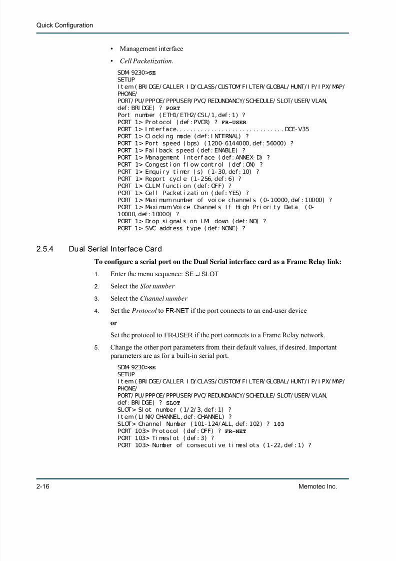
• Management interface
• Cell Packetization.
SDM- 9230> SESETUPI t em ( BRI DGE/ CALLER I D/ CLASS/ CUSTOM/ FI LTER/ GLOBAL/ HUNT/ I P/ I PX/ MAP/PHONE/PORT/ PU/ PPPOE/ PPPUSER/ PVC/ REDUNDANCY/ SCHEDULE/ SLOT/ USER/ VLAN,def : BRI DGE) ? PORTPort number ( ETH1/ ETH2/ CSL/ 1, def : 1) ?PORT 1> Pr ot ocol ( def : PVCR) ? FR-USER PORT 1> I nt er f ace. . . . . . . . . . . . . . . . . . . . . . . . . . . . . . . DCE- V35PORT 1> Cl ocki ng mode ( def : I NTERNAL) ?PORT 1> Por t speed ( bps) ( 1200- 6144000, def : 56000) ?PORT 1> Fal l back speed ( def : ENABLE) ?PORT 1> Management i nt er f ace ( def : ANNEX- D) ?PORT 1> Congest i on f l ow cont r ol ( def : ON) ?PORT 1> Enqui r y t i mer ( s) ( 1- 30, def : 10) ?PORT 1> Repor t cycl e (1- 256, def : 6) ?PORT 1> CLLM f unct i on ( def : OFF) ?PORT 1> Cel l Packet i zati on ( def : YES) ?PORT 1> Maxi mum number of voi ce channel s ( 0- 10000, def : 10000) ?PORT 1> Maxi mum Voi ce Channel s I f Hi gh Pr i or i t y Dat a ( 0-10000, def : 10000) ?PORT 1> Dr op si gnal s on LMI down ( def : NO) ?PORT 1> SVC addr ess t ype ( def : NONE) ?
2.5.4 Dual Serial Interface Card
To configure a serial port on the Dual Serial interface card as a Frame Relay link:
1. Enter the menu sequence: SE SLOT
2. Select the Slot number
3. Select the Channel number
4. Set the Protocol to FR-NET if the port connects to an end-user device
or
Set the protocol to FR-USER if the port connects to a Frame Relay network.
5. Change the other port parameters from their default values, if desired. Important parameters are as for a built-in serial port.
SDM- 9230> SESETUPI t em ( BRI DGE/ CALLER I D/ CLASS/ CUSTOM/ FI LTER/ GLOBAL/ HUNT/ I P/ I PX/ MAP/PHONE/PORT/ PU/ PPPOE/ PPPUSER/ PVC/ REDUNDANCY/ SCHEDULE/ SLOT/ USER/ VLAN,def : BRI DGE) ? SLOTSLOT> Sl ot number ( 1/ 2/ 3, def : 1) ?I t em ( LI NK/ CHANNEL, def : CHANNEL) ?SLOT> Channel Number ( 101- 124/ ALL, def : 102) ? 103PORT 103> Pr ot ocol ( def : OFF) ? FR-NETPORT 103> Ti mesl ot ( def : 3) ?PORT 103> Number of consecut i ve t i mesl ot s ( 1- 22, def : 1) ?

7/23/2019 04 Quick Configuration
http://slidepdf.com/reader/full/04-quick-configuration 25/102
WAN Configuration and Validation
Memotec Inc. 2-17
PORT 103> DS0 speed ( bps) ( def : 64000) ?PORT 103> Management i nt er f ace ( def : LMI ) ?PORT 103> Congest i on f l ow cont r ol ( def : ON) ?PORT 103> Enqui r y t i mer ( s) ( 1- 30, def : 10) ?PORT 103> CLLM f unct i on ( def : OFF) ?PORT 103> Cel l Packet i zat i on ( def : YES) ?PORT 103> Maxi mum number of voi ce channel s ( 0- 10000, def : 10000) ?
PORT 103> Maxi mum Voi ce Channel s I f Hi gh Pr i or i t y Dat a ( 0-10000, def : 10000) ?PORT 103> Ref erence port f or condi t i onal LMI ( def : 0) ?PORT 103> Dr op si gnal s on LMI down ( def : NO) ?
2.5.5 T1/E1 Channel
To configure a T1/E1 channel as a Frame Relay link:
1. Enter the menu sequence: SE SLOT
2. Select the Slot number
3. Enter CHANNEL at the Item prompt
4. Select the Channel number , e.g. 102 , where the first digit indicates the slot and thelast two digits indicate the channel
5. Set the Protocol to FR-NET if the channel connects to an end-user device
or
Set the protocol to FR-USER if the channel connects to a Frame Relay network.
6. Change the other port parameters from their default values, if desired. Important parameters are as for a built-in serial port.
For details on configuring a Frame Relay link, refer to the section Frame Relay PortConfiguration Parameters in the WAN/Frame Relay module of this document series.

7/23/2019 04 Quick Configuration
http://slidepdf.com/reader/full/04-quick-configuration 26/102
Quick Configuration
2-18 Memotec Inc.
2.5.6 Configuring the Logical Layer (PVCs)
A PVC provides a logical path between two network access points. Multiple PVCs can be bundled and attached to the same physical link on the NetPerformer.
All types of PVCs are configured with the PVC submenu of the SETUP command.
To configure a PVC:
1. Enter the menu sequence: SE PVC
2. Select the PVC number
3. Set the Mode parameter to the type of PVC required for your application
PVCR , RFC1490 , TRANSP and MULTIPLEX are the most commonly used modes.4. Select a unique DLCI address for this PVC
5. Change the other PVC parameters from their default values, if desired. Importantparameters are mentioned below for each PVC mode.
Figure 2-9: SETUP/PVC Path on the CLI Tree

7/23/2019 04 Quick Configuration
http://slidepdf.com/reader/full/04-quick-configuration 27/102
WAN Configuration and Validation
Memotec Inc. 2-19
2.5.7 PVCR over Frame Relay
Define a PVCR PVC to access a remote NetPerformer via a Frame Relay network usingPowerCell WAN connectivity. The local NetPerformer port must be a Frame Relay port(FR-USER or FR-NET protocol).
Important parameters include:
• Mode (PVCR )• Port
• DLCI address
• Remote unit name
• Type
• Compression .
MONTREAL>SESETUPI t em ( BRI DGE/ CALLER I D/ CLASS/ CUSTOM/ FI LTER/ GLOBAL/ HUNT/ I P/ I PX/ MAP/PHONE/PORT/ PU/ PPPOE/ PPPUSER/ PVC/ REDUNDANCY/ SCHEDULE/ SLOT/ USER/ VLAN,def : BRI DGE) ? PVCPVC number ( 1- 300, def : 1) ?PVC 1> Mode ( def : PVCR) ?PVC 1> Por t ( def : 1) ?PVC 1> DLCI address ( 0- 1022, def : 0) ? 101PVC 1> Commi t t ed I nf or mat i on r at e ( 4000- 6144000, def : 56000) ?PVC 1> Burst I nf or mat i on r at e ( 4000- 6144000, def : 56000) ?PVC 1> Remot e uni t name ( def : ) ? PARISPVC 1> Type ( def : DEDI CATED) ?PVC 1> Ti meout ( ms) ( 1000- 30000, def : 1000) ?PVC 1> Number of r et r ansmi ssi on r et r i es ( 1- 1000, def : 100) ?PVC 1> Compress i on ( def : YES) ?PVC 1> I P addr ess ( def : 000. 000. 000. 000) ?PVC 1> Subnet mask ( number of bi t s) ( 0- 24, def : 0) ?{000. 000. 000. 000}PVC 1> NAT enabl e ( def : NO) ?PVC 1> I P RI P ( def : V1) ?PVC 1> I P RI P TX/ RX ( def : DUPLEX) ?PVC 1> OSPF ( def : DI SABLE) ?PVC 1> I P mul t i cast act i ve ( def : NO) ?
Figure 2-10: PVCR PVC Scenario
7/23/2019 04 Quick Configuration
http://slidepdf.com/reader/full/04-quick-configuration 28/102
Quick Configuration
2-20 Memotec Inc.
PVC 1> I P mul t i cast pr ot ocol ( def : NONE) ?PVC 1> I PX RI P ( def : DI SABLE) ?PVC 1> I PX SAP ( def : DI SABLE) ?PVC 1> I PX NETWORK NUMBER (def : 00000000) ?PVC 1> Fi l t er ( def : ALL) ?PVC 1> Br oadcast group ( def : NO) ?PVC 1> Maxi mum number of voi ce channel s ( 0- 10000, def : 10000) ?
PVC 1> Maxi mum Voi ce Channel s I f Hi gh Pr i or i t y Dat a ( 0-10000, def : 10000) ?
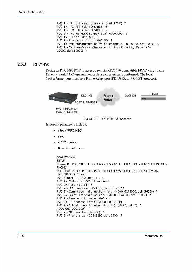
2.5.8 RFC1490
Define an RFC1490 PVC to access a remote RFC1490-compatible FRAD via a FrameRelay network. No fragmentation or data compression is performed. The local
NetPerformer port must be a Frame Relay port (FR-USER or FR-NET protocol).
Important parameters include:
• Mode (RFC1490 )
• Port
• DLCI address• Remote unit name.
SDM- 9230> SESETUPI t em ( BRI DGE/ CALLER I D/ CLASS/ CUSTOM/ FI LTER/ GLOBAL/ HUNT/ I P/ I PX/ MAP/PHONE/PORT/ PU/ PPPOE/ PPPUSER/ PVC/ REDUNDANCY/ SCHEDULE/ SLOT/ USER/ VLAN,def : BRI DGE) ? PVCPVC number ( 1- 300, def : 1) ? 2PVC 2> Mode ( def : OFF) ? RFC1490PVC 2> Por t ( def : 1) ?PVC 2> DLCI address ( 0- 1022, def : 0) ? 103PVC 2> Commi t t ed I nf or mat i on r at e ( 4000- 6144000, def : 56000) ?PVC 2> Burst I nf ormat i on r at e ( 4000- 6144000, def : 56000) ?PVC 2> Remot e uni t name ( def : ) ?PVC 2> I P addr ess ( def : 000. 000. 000. 000) ?PVC 2> Subnet mask ( number of bi t s) ( 0- 24, def : 0) ?{000. 000. 000. 000}PVC 2> NAT enabl e ( def : NO) ?PVC 2> Fr ame si ze ( 128- 8192, def : 1500) ?
Figure 2-11: RFC1490 PVC Scenario

7/23/2019 04 Quick Configuration
http://slidepdf.com/reader/full/04-quick-configuration 29/102
WAN Configuration and Validation
Memotec Inc. 2-21
PVC 2> I P RI P ( def : V1) ? V2 MULTICASTPVC 2> I P RI P TX/ RX ( def : DUPLEX) ? TX ONLYPVC 2> I P RI P Aut hent i cat i on ( def : NONE) ? SIMPLEPVC 2> I P RI P Password ( def : ) ?PVC 2> OSPF ( def : DI SABLE) ?PVC 2> I P mul t i cast act i ve ( def : NO) ?PVC 2> I P mul t i cast pr ot ocol ( def : NONE) ?
PVC 2> I PX RI P ( def : DI SABLE) ?PVC 2> I PX SAP ( def : DI SABLE) ?PVC 2> I PX NETWORK NUMBER ( def : 00000000) ?PVC 2> BRG connect i on ( def : NO) ? YESPVC 2> I P connect i on ( def : YES) ?PVC 2> I PX connect i on ( def : YES) ?PVC 2> LLC connect i on ( def : YES) ?PVC 2> Fi l t er ( def : ALL) ?
2.5.9 Transparent (TRANSP)
Define a TRANSP PVC to switch data from one end-user device over the Frame Relay
network to the destination end-user device without alteration on the frame. A TRANSPPVC requires either two network ports (FR-NET protocol) or one Frame Relay user port(FR-USER protocol) and one network port.
Important parameters include:
• Mode (TRANSP )
• User port
Figure 2-12: TRANSP PVC Scenario

7/23/2019 04 Quick Configuration
http://slidepdf.com/reader/full/04-quick-configuration 30/102
Quick Configuration
2-22 Memotec Inc.
• Network port
• User DLCI
• Network DLCI.
NEW YORK>SE
SETUPI t em ( BRI DGE/ CALLER I D/ CLASS/ CUSTOM/ FI LTER/ GLOBAL/ HUNT/ I P/ I PX/ MAP/PHONE/PORT/ PU/ PPPOE/ PPPUSER/ PVC/ REDUNDANCY/ SCHEDULE/ SLOT/ USER/ VLAN,def : BRI DGE) ? PVCPVC number ( 1- 300, def : 5) ? 1PVC 1> Mode ( def : OFF) ? TRANSPPVC 1> User por t ( def : 1) ? 1PVC 1> Net work por t ( def : 1) ? 2PVC 1> User DLCI ( 0- 1022, def : 0) ? 101PVC 1> Net wor k DLCI ( 0- 1022, def : 0) ? 102PVC 1> Commi t t ed I nf or mat i on r at e ( 4000- 6144000, def : 56000) ?PVC 1> Burst I nf ormat i on r at e ( 4000- 6144000, def : 56000) ?

7/23/2019 04 Quick Configuration
http://slidepdf.com/reader/full/04-quick-configuration 31/102
WAN Configuration and Validation
Memotec Inc. 2-23
2.5.10 MULTIPLEX
Define a MULTIPLEX PVC to multiplex traffic from a Frame Relay end-user device. Theassociated port must be set to the FR-NET protocol (or X.25, in the case of X.25encapsulation to Frame Relay). A MULTIPLEX solution allows the connection to carrytraffic from multiple sources, with multiplexing performed at the local site, and
demultiplexing at the remote site.
Important parameters include:
• Mode (MULTIPLEX )
• Port
• DLCI address
• Remote unit name
• Remote PVC number
• Compression.
MONTREAL>SESETUPI t em ( BRI DGE/ CALLER I D/ CLASS/ CUSTOM/ FI LTER/ GLOBAL/ HUNT/ I P/ I PX/ MAP/PHONE/PORT/ PU/ PPPOE/ PPPUSER/ PVC/ REDUNDANCY/ SCHEDULE/ SLOT/ USER/ VLAN,def : BRI DGE) ? PVCPVC number ( 1- 300, def : 3) ? 2
Figure 2-13: MULTIPLEX PVC Scenario

7/23/2019 04 Quick Configuration
http://slidepdf.com/reader/full/04-quick-configuration 32/102
Quick Configuration
2-24 Memotec Inc.
PVC 2> Mode ( def : OFF) ? MULTIPLEXPVC 2> Por t ( def : 1) ? 2PVC 2> DLCI address ( 0- 1022, def : 0) ? 501PVC 2> Commi t t ed I nf or mat i on r at e ( 4000- 6144000, def : 56000) ?PVC 2> Burst I nf ormat i on r at e ( 4000- 6144000, def : 56000) ?PVC 2> Remot e uni t name ( def : ) ? PARISPVC 2> Remot e PVC number ( 1- 300, def : 2) ? 3
PVC 2> Cl ass number ( def : 3) ?PVC 2> Compressi on ( def : YES) ?
2.5.11 Other PVC Types
• BROADCAST : The PVC is used to send broadcast frames to the multicast server(the Frame Relay switch). The DLCI you define for this PVC is the Mdlci. Thelocal NetPerformer port must be an analog voice port.
• FP : The PVC is used over a Frame Relay network to transport data to a remoteSDM-FP (legacy product). The local NetPerformer port must be a Frame Relay
port (FR-USER or FR-NET protocol).
• FP-MULTIPLEX : The PVC is used to switch data coming from an SDM-FP via alegacy NetPerformer unit. The corresponding PVC on the legacy NetPerformerunit should be set to MULTIPLEX mode.
For details on configuring a PVC, refer to the section PVC Configuration Parameters inthe WAN/Frame Relay module of this document series.
2.5.12 Displaying WAN/Frame Relay Link Status
• To view the current PowerCell routing table , use the Display Destination Table(DD) command. See “Displaying the PowerCell Routing Table” on page 2-4 .
• For a continuous display of WAN link status in real time , use the Display PortStates ( DPORT ) command. See “Real-time Display of WAN Link Status” on
page 2-6 .
• For a continuous display of PVC status in real time , use the Display PVC States(DPVC ) command, as outlined below.
• For a continuous display of DLCI status in r eal time , use the Display PVC DLCIStates ( DDLCI) command, as outlined below.

7/23/2019 04 Quick Configuration
http://slidepdf.com/reader/full/04-quick-configuration 33/102
WAN Configuration and Validation
Memotec Inc. 2-25
Real-time Display of PVC Status
To view the current status of all PVCs in real time:
1. Enter DPVC at the main command prompt
2. Navigate the display using the <Home> , <End> , <Up Arro w> and <Down Arro w> keys
The various statistics in the DPVC display are updated dynamically and continu-ously refreshed on the screen.
3. To quit from the DPVC screen, press any key other than the navigation keys.
SDM- 9230> DPVCDI SPLAY PVC STATES- - - - - - - - - - - - - - - - - - - - - - - - - - - - - - - - - - - FR PVC- - - - - - - - - - - - - - - - - - - - - - - - - - - - - - - - - - - - -
- -| PVC MODE I NFO. SPEED PORT DLCI DESTI NATI ON STATE & || SI GNALS ( BPS) NAME DELAY(MS) |- - - - - - - - - - - - - - - - - - - - - - - - - - - - - - - - - - - - - - - - - - - - - - - - - - - - - - - - - - - - - - - - - - - - - - - - - - - - - -
- -| 1 PVCR of f l i ne 56000 WAN 1 102 CHI CAGO- 9230 CALL || 2 PVCR of f l i ne 56000 WAN 1 103 CHI CAGO- 9230 OFF || 3 PVCR of f l i ne 56000 WAN 1 0 OFF || 4 MULTI PLEX MULT - - - - - 56000 WAN 1 0 CHI CAGO- 9230 I DLE || 5 BROADCAST of f l i ne 56000 WAN 1 0 I DLE || 6 TRANSP- USR USER - - - - - 56000 WAN 1 0 I DLE || 6 TRANSP- NET USER - - - - - 56000 WAN 1 0 I DLE || 7 FP of f l i ne 56000 WAN 1 0 DOWN || 8 FP- MULTI PLEX MULT - - - - - - - - - - CHI CAGO- 9230 CALL || || || || || |
| I nf ormat i on si gnal s: NETwor k/ USER ( N) ew ( A) cti ve ( C) i r ( F)ecn ( B) ecn ( - ) of f |- - - - - - - - - - - - - - - - - - - - - - - - - - - - - - - - - - - - - - - - - - - - - - - - - - - - - - - - - - - - - - - - - - - - - - - - - - - - - -- -
Use HOME, END, UP and DOWN ar r ow keys t o scr ol l . Pr ess any ot her key t o exi t .
Figure 2-14: DD, DPORT, DPVC and DDLCI Paths on the CLI Tree

7/23/2019 04 Quick Configuration
http://slidepdf.com/reader/full/04-quick-configuration 34/102
Quick Configuration
2-26 Memotec Inc.
2.5.13 Real-time Display of PVC DLCI Status
To view the current status of all PVC DLCIs in real time:
1. Enter DDLCI at the main command prompt
2. Navigate the display using the <Home> , <End> , <Up Arro w> and <Down Arro w> keys
The various statistics in the DDLCI display are updated dynamically andcontinuously refreshed on the screen.
3. To quit from the DDLCI screen, press any key other than the navigation keys.
SDM- 9380> DDLCIDI SPLAY PVC DLCI STATES- - - - - - - - - - - - - - - - - - - - - - - - - - - - - - - - - - - - - - - - - - - - - - - - - - - - - - - - - - - - - - - - - - - - - - - - - - - - - -
- -| DLCI PVC MODE I NFO. SPEED PORT DESTI NATI ON STATE & || SI GNALS ( BPS) NAME DELAY( MS) |- - - - - - - - - - - - - - - - - - - - - - - - - - - - - - - - - - - - - - - - - - - - - - - - - - - - - - - - - - - - - - - - - - - - - - - - - - - - - -
- -
| 22 4 MULTI PLEX MULT - A- - - 64000 WAN 3 FR. 60- 2 DATA || 101 2 PVCR USER - A- - - 512 k WAN 201 FR. 80- 3 DATA 25ms || 102 3 RFC1490 USER - A- - - 512 k WAN 201 DATA 0ms || 211 5 PVCR USER - A- - - 1024 k WAN 1 FR. 60- 3 DATA 17ms || 212 1 PVCR USER - A- - - 1024 k WAN 1 FR. 80 DATA 14ms || || || || || || || || || || |
| || || || I nf ormati on si gnal s: NETwor k/ USER ( N) ew ( A) ct i ve ( C) i r ( F)ecn ( B) ecn ( - ) off
|- - - - - - - - - - - - - - - - - - - - - - - - - - - - - - - - - - - - - - - - - - - - - - - - - - - - - - - - - - - - - - - - - - - - - - - - - - - - - -
- - Use HOME, END, UP and DOWN ar r ow keys t o scr ol l . Pr ess any ot her key t o exi t .
7/23/2019 04 Quick Configuration
http://slidepdf.com/reader/full/04-quick-configuration 35/102
WAN Configuration and Validation
Memotec Inc. 2-27
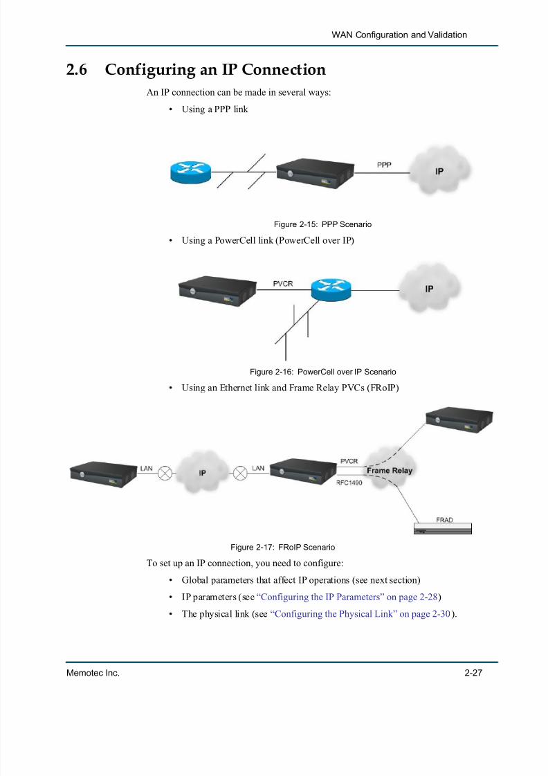
2.6 Configuring an IP ConnectionAn IP connection can be made in several ways:
• Using a PPP link
• Using a PowerCell link (PowerCell over IP)
• Using an Ethernet link and Frame Relay PVCs (FRoIP)
To set up an IP connection, you need to configure:
• Global parameters that affect IP operations (see next section)
• IP parameters (see “Configuring the IP Parameters” on page 2-28 )
• The physical link (see “Configuring the Physical Link” on page 2-30 ).
Figure 2-15: PPP Scenario
Figure 2-16: PowerCell over IP Scenario
Figure 2-17: FRoIP Scenario

7/23/2019 04 Quick Configuration
http://slidepdf.com/reader/full/04-quick-configuration 36/102
Quick Configuration
2-28 Memotec Inc.
2.6.1 Configuring the Global Parameters
To configure the global parameters that affect IP operations:
1. Enter the menu sequence: SE GLOBAL
Refer to Figure 4-7 for the SETUP/GLOBAL path in the CLI tree.
2. Change the IP and FRoIP parameters from their default values, if desired:- Default IP address
- Default IP mask
- Default gateway
- Global CIR for FR over IP
- Timer in ms for FR over IP .
For further information on these parameters, consult the appendix “SE/GLOBALConfiguration Parameters” on page 5-1 .
2.6.2 Configuring the IP Parameters
The IP parameters are configured with the IP submenu of the SETUP command. Theycontrol:
• General IP routing characteristics, using the SETUP/IP/GLOBAL submenu
• IP routing to a particular destination when RIP is disabled, using the SETUP/IP/STATIC submenu.
Figure 2-18: SETUP/IP/GLOBAL and SETUP/IP/STATIC Paths on the CLI Tree

7/23/2019 04 Quick Configuration
http://slidepdf.com/reader/full/04-quick-configuration 37/102
WAN Configuration and Validation
Memotec Inc. 2-29
To configure the general IP routing characteristics:
1. Enter the menu sequence: SE IP GLOBAL
2. Set the Router to ENABLE
3. Change the other parameters from their default values, if desired.
SDM- 9230> SESETUPI t em ( BRI DGE/ CALLER I D/ CLASS/ CUSTOM/ FI LTER/ GLOBAL/ HUNT/ I P/ I PX/ MAP/PHONE/PORT/ PU/ PPPOE/ PPPUSER/ PVC/ REDUNDANCY/ SCHEDULE/ SLOT/ USER/ VLAN,def : BRI DGE) ? IPI t em ( GLOBAL/ STATI C/ BOOTP/ OSPF/ TI MEP/ SNMP/ NAT/ TELNET/ FTP/ DNS/RADI US,def : GLOBAL) ?I P> Rout er ( def : ENABLE) ?I P> Rout e br oadcast t o end st at i on ( def : NO) ?I P> OSPF AS boundar y rout er ( def : NO) ?I P> RI P AS boundar y rout er ( def : NO) ?
I P> I P Precedence f or FR over I P (0- 7, def : 0) ?
To configure a static IP address:
1. Enter the menu sequence: SE IP STATIC
2. Select an IP static entry number
3. Define the Destination address and Subnet mask
4. Define the Next hop to reach this destination, if required.
SDM- 9230> SESETUPI t em ( BRI DGE/ CALLER I D/ CLASS/ CUSTOM/ FI LTER/ GLOBAL/ HUNT/ I P/ I PX/ MAP/PHONE/PORT/ PU/ PPPOE/ PPPUSER/ PVC/ REDUNDANCY/ SCHEDULE/ SLOT/ USER/ VLAN,def : BRI DGE) ? IPI t em ( GLOBAL/ STATI C/ BOOTP/ OSPF/ TI MEP/ SNMP/ NAT/ TELNET/ FTP/ DNS/RADI US,def : GLOBAL) ? STATICI P st at i c ent r y number ( 1- 200, def : 1) ?I P STATI C 1> Val i d (def : NO) ? YESI P STATI C 1> Dest i nat i on addr ess ( def : 000. 000. 000. 000) ?128.130.0.2I P STATI C 1> Subnet mask ( number of bi t s) ( 0- 24, def : 0) ? 8 {255. 255. 000. 000}I P STATI C 1> Next hop ( def : 000. 000. 000. 000) ? 128.129.0.2

7/23/2019 04 Quick Configuration
http://slidepdf.com/reader/full/04-quick-configuration 38/102
Quick Configuration
2-30 Memotec Inc.
Example addresses:
2.6.3 Conf igur ing the Phys ical Link
The physical link provides LAN/WAN connectivity between a NetPerformer unit and:
• The IP cloud, using PPP ( Figure 2-15 )
• Another router, using PowerCell over IP ( Figure 2-16 )
• Another FRAD, using FRoIP ( Figure 2-17 ).The physical link may be:
• An Ethernet port
• A serial port
• A T1/E1 channel.
Figure 2-19: Static IP Address Scenario
Parameter Local Unit Remote Unit
IP Addr. of attached device: 128.128.0.1 128.130.0.1
IP Mask of attached device: 255.255.0.0 255.255.0.0
Default Gateway: 0.0.0.0 0.0.0.0
Default IP Address: 0.0.0.0 0.0.0.0
Default IP Mask: 0.0.0.0 0.0.0.0
LAN IP Address: 128.128.0.2 128.130.0.2
LAN IP Mask: 255.255.0.0 255.255.0.0
PVCR IP Address: 128.129.0.1 128.129.0.2PVCR IP Mask: 255.255.0.0 255.255.0.0
Table 2-2: Examples of possible static IP addresses

7/23/2019 04 Quick Configuration
http://slidepdf.com/reader/full/04-quick-configuration 39/102
WAN Configuration and Validation
Memotec Inc. 2-31
The physical link is configured with the PORT or SLOT submenu of the SETUP command.
2.6.4 Ethernet Port
To configure the Ethernet port:
1. Enter the menu sequence: SE PORT
2. Select ETH , ETH1 or ETH2 as the Port number
Available values are product-dependant
3. Define the IP address and Subnet mask
Two IP addresses can be defined on later NetPerformer products.
4. Select the IP RIP version.
5. Change the other port parameters from their default values, if desired. Important parameters include:
• DHCP• IGMP enable.
SDM- 9230> SESETUPI t em ( BRI DGE/ CALLER I D/ CLASS/ CUSTOM/ FI LTER/ GLOBAL/ HUNT/ I P/ I PX/ MAP/PHONE/
Figure 2-20: SETUP/PORT and SETUP/SLOT/CHANNEL Paths on theCLI Tree for the IP Physical Link

7/23/2019 04 Quick Configuration
http://slidepdf.com/reader/full/04-quick-configuration 40/102
Quick Configuration
2-32 Memotec Inc.
PORT/ PU/ PPPOE/ PPPUSER/ PVC/ REDUNDANCY/ SCHEDULE/ SLOT/ USER/ VLAN,def : BRI DGE) ? PORTPort number ( ETH1/ ETH2/ CSL/ 1, def : ETH1) ?PORT ETH 1> Pr ot ocol ( def : ETH AUTO) ?PORT ETH 1> LAN speed ( mbps) ( def : AUTO) ?PORT ETH 1> MAC address ( def : 000000000000) ?PORT ETH 1> DHCP ( def : DI SABLE) ?
PORT ETH 1> I P address 1 ( def : 000. 000. 000. 000) ? 128.130.0.1PORT ETH 1> Subnet mask 1 (number of bi t s) ( 0- 24, def : 0) ? 16 {255. 255. 255. 000}PORT ETH 1> I P address 2 ( def : 000. 000. 000. 000) ?PORT ETH 1> Subnet mask 2 (number of bi t s) ( 0- 24, def : 0) ?{000. 000. 000. 000}PORT ETH 1> Fr ame si ze ( 128- 8192, def : 1500) ?PORT ETH 1> I P RI P ( def : V1) ?PORT ETH 1> I P RI P TX/ RX ( def : DUPLEX) ?PORT ETH 1> OSPF ( def : DI SABLE) ?PORT ETH 1> I GMP enabl e ( def : NO) ?PORT ETH 1> I P mul t i cast act i ve ( def : NO) ?PORT ETH 1> I P mul t i cast prot ocol ( def : NONE) ?PORT ETH 1> NAT enabl e ( def : NO) ?PORT ETH 1> VLAN enabl e ( def : NO) ?PORT ETH 1> I PX RI P ( def : DI SABLE) ?PORT ETH 1> I PX SAP ( def : DI SABLE) ?PORT ETH 1> I PX net wor k number ( def : 00000000) ?PORT ETH 1> I PX encapsul at i on ( def : ETH 802. 2) ?PORT ETH 1> Physi cal connect i vi t y det ect i on ( def : DI SABLE) ?
For details on configuring an Ethernet port, refer to the LAN Connection and IPNetworks module of this document series.
2.6.5 Buil t-in Ser ial Por t
To configure a built-in serial port as an IP link:1. Enter the menu sequence: SE PORT
2. Select the Port number
3. Set the Protocol to:
• PPP , to access the IP cloud directly using PPP
• PVCR , for PowerCell over IP.
4. Change the other port parameters from their default values, if desired. Important parameters include:
• IP address
• Subnet mask
• IP RIP
SDM- 9230> SESETUPI t em ( BRI DGE/ CALLER I D/ CLASS/ CUSTOM/ FI LTER/ GLOBAL/ HUNT/ I P/ I PX/ MAP/

7/23/2019 04 Quick Configuration
http://slidepdf.com/reader/full/04-quick-configuration 41/102
WAN Configuration and Validation
Memotec Inc. 2-33
PHONE/PORT/ PU/ PPPOE/ PPPUSER/ PVC/ REDUNDANCY/ SCHEDULE/ SLOT/ USER/ VLAN,def : BRI DGE) ? PORTPor t number ( ETH1/ ETH2/ CSL/ 1, def : 1) ?PORT 1> Pr ot ocol ( def : PPP) ?PORT 1> Por t Cl ocki ng ( def : ASYNC) ? SYNCPORT 1> I nt er f ace. . . . . . . . . . . . . . . . . . . . . . . . . . . . . . . DCE- V35
PORT 1> Cl ocki ng mode ( def : I NTERNAL) ?PORT 1> Por t speed ( bps) ( 1200- 6144000, def : 56000) ?PORT 1> CRC encodi ng ( def : NRZ) ?PORT 1> I dl e ( def : FLAG) ?PORT 1> Fr ame del ay ( ms) ( def : 0. 0) ?PORT 1> I P address ( def : 000. 000. 000. 000) ? 128.130.0.2PORT 1> Subnet mask ( number of bi t s) ( 0- 24, def : 0) ? 16 {255. 255. 255. 000}PORT 1> I P RI P ( def : V1) ?PORT 1> I P RI P TX/ RX ( def : DUPLEX) ?PORT 1> NAT enabl e ( def : NO) ?PORT 1> Si l ent ( def : SEND REQUEST) ?PORT 1> LCP t i meout ( s) ( 1- 255, def : 3) ?PORT 1> LCP r et r i es, 255 = f orever ( 0- 255, def : 255) ?PORT 1> Negot i at e MRU ( def : NO) ?PORT 1> Use MRU pr oposed by peer ( def : NO) ?PORT 1> Request Magi c Number ( def : YES) ?PORT 1> Accept Magi c Number Request ( def : YES) ?PORT 1> Accept Addr esses Ol d Negot i at i on ( def : NO) ?PORT 1> Request I P- Addr ess ( def : NO) ?PORT 1> Accept I P- Addr ess Request ( def : NO) ?PORT 1> Fi l t er ( def : ALL) ?PORT 1> PPP di al i ndex ( def : NONE) ?
SDM- 9230> SESETUPI t em ( BRI DGE/ CALLER I D/ CLASS/ CUSTOM/ FI LTER/ GLOBAL/ HUNT/ I P/ I PX/ MAP/PHONE/PORT/ PU/ PPPOE/ PPPUSER/ PVC/ REDUNDANCY/ SCHEDULE/ SLOT/ USER/ VLAN,def : BRI DGE) ? PORTPor t number ( ETH1/ ETH2/ CSL/ 1, def : 1) ?PORT 1> Pr ot ocol ( def : PPP) ? PVCR PORT 1> I nt er f ace. . . . . . . . . . . . . . . . . . . . . . . . . . . . . . . DCE- V35PORT 1> Cl ocki ng mode ( def : I NTERNAL) ?PORT 1> Por t speed ( bps) ( 1200- 6144000, def : 56000) ?PORT 1> Mode ( def : DEDI CATED) ?PORT 1> I P address ( def : 000. 000. 000. 000) ? 128.130.0.3PORT 1> Subnet mask ( number of bi t s) ( 0- 24, def : 0) ? 16 {255. 255. 255. 000}PORT 1> I P RI P ( def : V1) ?PORT 1> I P RI P TX/ RX ( def : DUPLEX) ?PORT 1> OSPF ( def : DI SABLE) ?PORT 1> I P mul t i cast act i ve ( def : NO) ?PORT 1> I P mul t i cast pr ot ocol ( def : NONE) ?PORT 1> NAT enabl e ( def : NO) ?PORT 1> I PX RI P ( def : DI SABLE) ?PORT 1> I PX SAP ( def : DI SABLE) ?PORT 1> I PX net wor k number ( def : 00000000) ?PORT 1> Compr ess i on ( def : YES) ?

7/23/2019 04 Quick Configuration
http://slidepdf.com/reader/full/04-quick-configuration 42/102
Quick Configuration
2-34 Memotec Inc.
PORT 1> Remot e uni t name ( def : ) ? CHICAGO-9230PORT 1> Ti meout ( ms) ( 1000- 30000, def : 1000) ?PORT 1> Number of r et r ansmi ssi on r et r i es ( 1- 1000, def : 100) ?PORT 1> Maxi mum number of voi ce channel s ( 0- 10000, def : 10000) ?PORT 1> Maxi mum Voi ce Channel s I f Hi gh Pr i or i t y Dat a ( 0-10000, def : 10000) ?PORT 1> Cel l Packet i zati on ( def : YES) ?
PORT 1> Fi l t er ( def : ALL) ?
2.6.6 Dual Serial Interface Card
To configure a serial port on the Dual Serial interface card as an IP link:
1. Enter the menu sequence: SE SLOT
2. Select the Slot number
3. Select the Channel number
4. Set the Protocol to:
• PPP , to access the IP cloud directly using PPP
• PVCR , for PowerCell over IP.
5. Change the other port parameters from their default values, if desired. Important parameters are as for a built-in serial port.
SDM- 9230> SESETUPI t em ( BRI DGE/ CALLER I D/ CLASS/ CUSTOM/ FI LTER/ GLOBAL/ HUNT/ I P/ I PX/ MAP/PHONE/PORT/ PU/ PPPOE/ PPPUSER/ PVC/ REDUNDANCY/ SCHEDULE/ SLOT/ USER/ VLAN,def : BRI DGE) ? SLOT
SLOT> Sl ot number ( 1/ 2/ 3, def : 2) ?SLOT> Channel Number ( 201- 202/ ALL, def : 202) ? 201PORT 201> Pr ot ocol ( def : PPP) ? PVCR PORT 201> I nt er f ace. . . . . . . . . . . . . . . . . . . . . . . . . . . . . DCE- V35PORT 201> Cl ocki ng mode ( def : I NTERNAL) ?PORT 201> Por t speed ( bps) ( 1200- 2048000, def : 56000) ?PORT 201> Mode ( def : DEDI CATED) ?PORT 201> I P address ( def : 000. 000. 000. 000) ? 128.130.0.4PORT 201> Subnet mask ( number of bi t s) ( 0- 24, def : 0) ? 16 {255. 255. 255. 000}PORT 201> I P RI P ( def : V1) ?PORT 201> I P RI P TX/ RX ( def : DUPLEX) ?PORT 201> OSPF ( def : DI SABLE) ?PORT 201> I P mul t i cast act i ve ( def : NO) ?
PORT 201> I P mul t i cast prot ocol ( def : NONE) ?PORT 201> NAT enabl e ( def : NO) ?PORT 201> I PX RI P ( def : DI SABLE) ?PORT 201> I PX SAP ( def : DI SABLE) ?PORT 201> I PX net wor k number ( def : 00000000) ?PORT 201> Compr ess i on ( def : YES) ?PORT 201> Remot e uni t name ( def : ) ?PORT 201> Ti meout ( ms) ( 1000- 30000, def : 1000) ?
7/23/2019 04 Quick Configuration
http://slidepdf.com/reader/full/04-quick-configuration 43/102
WAN Configuration and Validation
Memotec Inc. 2-35
PORT 201> Number of r et r ansmi ssi on r et r i es ( 1- 1000, def : 100) ?PORT 201> Maxi mum number of voi ce channel s ( 0- 10000, def : 10000) ?PORT 201> Maxi mum Voi ce Channel s I f Hi gh Pr i or i t y Dat a ( 0-10000, def : 10000) ?PORT 201> Cel l Packet i zat i on ( def : YES) ?PORT 201> Fi l t er ( def : ALL) ?
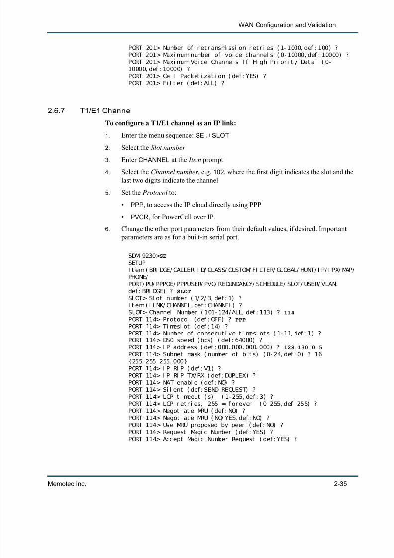
2.6.7 T1/E1 Channel
To configure a T1/E1 channel as an IP link:
1. Enter the menu sequence: SE SLOT
2. Select the Slot number
3. Enter CHANNEL at the Item prompt
4. Select the Channel number , e.g. 102 , where the first digit indicates the slot and thelast two digits indicate the channel
5. Set the Protocol to:• PPP , to access the IP cloud directly using PPP
• PVCR , for PowerCell over IP.
6. Change the other port parameters from their default values, if desired. Important parameters are as for a built-in serial port.
SDM- 9230> SESETUPI t em ( BRI DGE/ CALLER I D/ CLASS/ CUSTOM/ FI LTER/ GLOBAL/ HUNT/ I P/ I PX/ MAP/PHONE/PORT/ PU/ PPPOE/ PPPUSER/ PVC/ REDUNDANCY/ SCHEDULE/ SLOT/ USER/ VLAN,
def : BRI DGE) ? SLOTSLOT> Sl ot number ( 1/ 2/ 3, def : 1) ?I t em ( LI NK/ CHANNEL, def : CHANNEL) ?SLOT> Channel Number ( 101- 124/ ALL, def : 113) ? 114PORT 114> Pr ot ocol ( def : OFF) ? PPPPORT 114> Ti mesl ot ( def : 14) ?PORT 114> Number of consecut i ve t i mesl ot s ( 1- 11, def : 1) ?PORT 114> DS0 speed ( bps) ( def : 64000) ?PORT 114> I P addr ess ( def : 000. 000. 000. 000) ? 128.130.0.5PORT 114> Subnet mask ( number of bi t s) ( 0- 24, def : 0) ? 16{255. 255. 255. 000}PORT 114> I P RI P ( def : V1) ?PORT 114> I P RI P TX/ RX ( def : DUPLEX) ?PORT 114> NAT enabl e ( def : NO) ?
PORT 114> Si l ent ( def : SEND REQUEST) ?PORT 114> LCP t i meout ( s) ( 1- 255, def : 3) ?PORT 114> LCP r et r i es, 255 = f or ever ( 0- 255, def : 255) ?PORT 114> Negot i at e MRU ( def : NO) ?PORT 114> Negot i at e MRU ( NO/ YES, def : NO) ?PORT 114> Use MRU pr oposed by peer ( def : NO) ?PORT 114> Request Magi c Number ( def : YES) ?PORT 114> Accept Magi c Number Request ( def : YES) ?

7/23/2019 04 Quick Configuration
http://slidepdf.com/reader/full/04-quick-configuration 44/102
Quick Configuration
2-36 Memotec Inc.
PORT 114> Accept Addr esses Ol d Negot i at i on ( def : NO) ?PORT 114> Request I P- Addr ess ( def : NO) ?PORT 114> Accept I P- Addr ess Request ( def : NO) ?PORT 114> Remot e I P- Addr ess ( def : 000. 000. 000. 000) ?PORT 114> Fi l t er ( def : ALL) ?
For details on configuring a serial port or T1/E1 channel as an IP link, refer to the LANConnection and IP Networks module of this document series.
2.6.8 Configure the Logical Layer (PVCs)
PVCs are required for an FRoIP application, and use the Ethernet port as the physical link(see Figure 2-17 ). Only PVCR or RFC1490 mode can be used. Both of these types ofPVCs are configured with the PVC submenu of the SETUP command.
To configure a PVC for FRoIP:
1. Enter the menu sequence: SE PVC
2. Select the PVC number
3. Set the Mode parameter to:
• PVCR , to access a remote NetPerformer
• RFC1490 , to access another type of FRAD
4. Set the Port to 05. Select a unique DLCI address for this PVC
6. Define the Frame over IP, source
7. Define the Frame over IP, destination
Figure 2-21: SETUP/PVC Path on the CLI Tree, for FRoIP

7/23/2019 04 Quick Configuration
http://slidepdf.com/reader/full/04-quick-configuration 45/102
7/23/2019 04 Quick Configuration
http://slidepdf.com/reader/full/04-quick-configuration 46/102
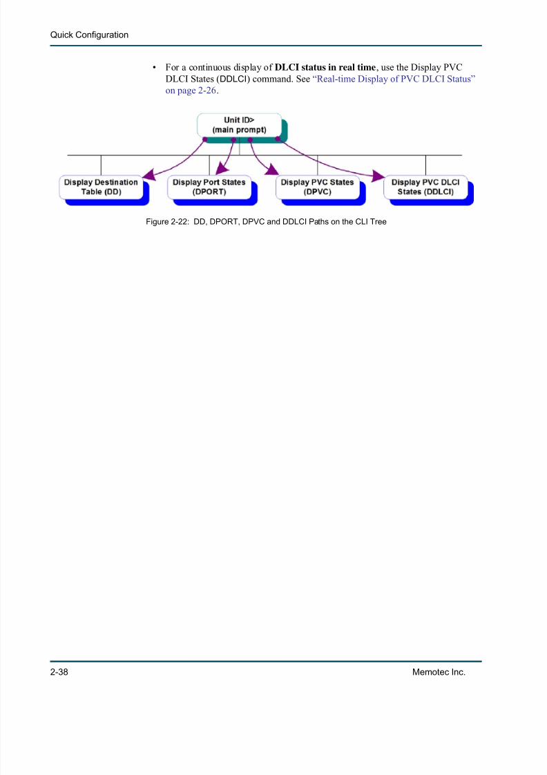
Quick Configuration
2-38 Memotec Inc.
• For a continuous display of DLCI status in real time , use the Display PVCDLCI States ( DDLCI ) command. See “Real-time Display of PVC DLCI Status”on page 2-26 .
Figure 2-22: DD, DPORT, DPVC and DDLCI Paths on the CLI Tree

7/23/2019 04 Quick Configuration
http://slidepdf.com/reader/full/04-quick-configuration 47/102
3
Memotec Inc. 3-1
Country-specific Factory Setup

7/23/2019 04 Quick Configuration
http://slidepdf.com/reader/full/04-quick-configuration 48/102
Quick Configuration
3-2 Memotec Inc.
3.1 Applyign the Country CodeThe factory setup can be customized to the country code you would like to use for voice/fax communications. This permits country-specific default settings for certain voice port
parameters.
NOTE: For a brief explanation of the Factory Setup ( FS ) command, refer to the sec-tion Resetting the Configuration in the Getting Started module of thisdocument series.
To select a country-specific factory setup:
1. Enter FS at the main command prompt
2. Enter NO at the confirmation prompt
3. Enter the Country Code
NOTE: If you do not know your country code, enter ? to display a list of all availablecountry codes in alphabetical order by country. At the end of this list theCountry code prompt is displayed again.
4. Enter YES at the confirmation prompt to start the factory setup, as in the followingexample.
SDM- 9230> FS
FACTORY SETUPDef aul t f act or y set up ( NO/ YES, def : YES) ? NOCount r y code ( 0- 9999, def : 1) ? ?Al geri a => 213Argent i na => 54Aust r al i a => 61Aust r i a => 43Bel gi um => 32Bol i vi a => 591Br azi l => 55Bul gar i a => 359Canada => 1Chi l e => 56Chi na => 86Col ombi a => 57Cost a Ri ca => 506Cypr us => 357Czech Republ i c => 42Denmar k => 45Ecuador => 593Egypt => 20El Sal vador => 503
7/23/2019 04 Quick Configuration
http://slidepdf.com/reader/full/04-quick-configuration 49/102
Country-specific Factory Setup
Memotec Inc. 3-3
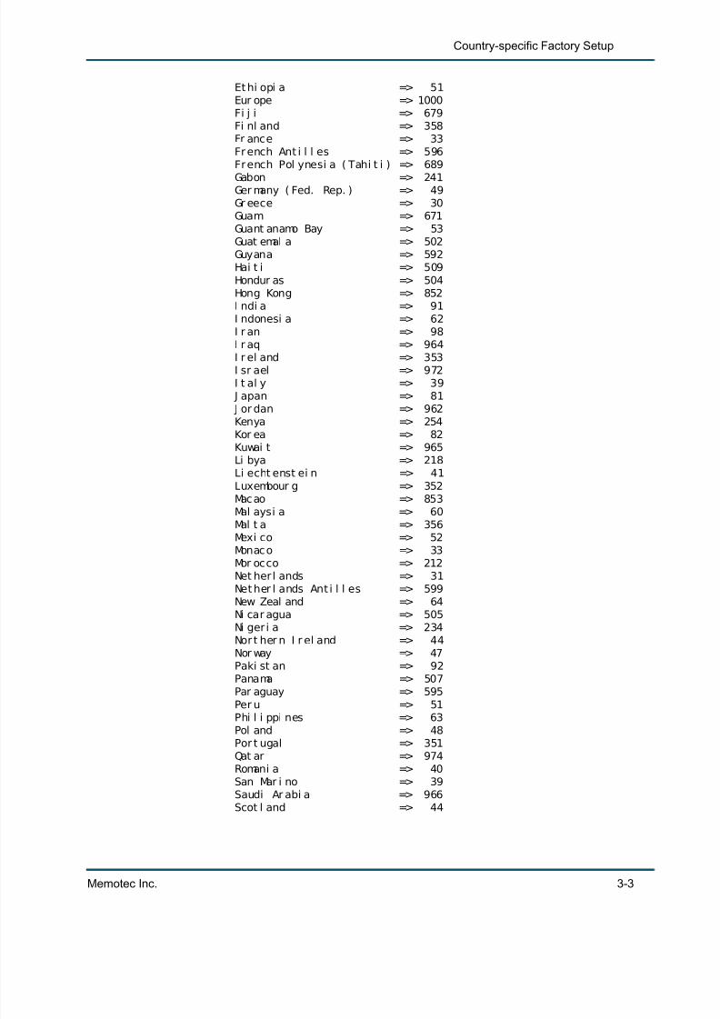
Et hi opi a => 51Eur ope => 1000Fi j i => 679Fi nl and => 358Fr ance => 33Fr ench Ant i l l es => 596Fr ench Pol ynesi a ( Tahi t i ) => 689
Gabon => 241Ger many ( Fed. Rep. ) => 49Gr eece => 30Guam => 671Guant anamo Bay => 53Guat emal a => 502Guyana => 592Hai t i => 509Hondur as => 504Hong Kong => 852I ndi a => 91I ndonesi a => 62I r an => 98I r aq => 964I r el and => 353I sr ael => 972I t al y => 39
J apan => 81 J or dan => 962Kenya => 254Kor ea => 82Kuwai t => 965Li bya => 218Li echt enst ei n => 41Luxembour g => 352Macao => 853Mal aysi a => 60Mal t a => 356Mexi co => 52Monaco => 33Mor occo => 212Net her l ands => 31Net her l ands Ant i l l es => 599New Zeal and => 64Ni car agua => 505Ni ger i a => 234Nor t her n I r el and => 44Nor way => 47Paki st an => 92Panama => 507Par aguay => 595Per u => 51Phi l i ppi nes => 63Pol and => 48Por t ugal => 351Qat ar => 974Romani a => 40San Mar i no => 39Saudi Ar abi a => 966Scot l and => 44

7/23/2019 04 Quick Configuration
http://slidepdf.com/reader/full/04-quick-configuration 50/102
Quick Configuration
3-4 Memotec Inc.
Senegal => 221Si ngapor e => 65Sout h Af r i ca => 27Spai n => 34Sr i Lanka => 94Suri nam => 597Sweden => 46
Swi t zer l and => 41 Tahi t i ( Fr ench Pol ynesi a) => 689 Tai wan => 886 Tanzani a => 255 Tasmani a => 61 Thai l and => 66 Tuni si a => 216 Turkey => 90Uganda => 256Uni t ed Ar ab Emi r at es => 971Uni t ed Ki ngdom => 44Uni t ed St at es of Amer i ca => 1Uruguay => 598Vat i can Ci t y => 39Venezuel a => 58Wal es => 44
Yugosl avi a => 38Zai r e, Rep. => 243Zambi a => 260Zi mbabwe => 263Count r y code ( 0- 9999, def : 1) ? 44Fact ory set up, pl ease conf i r m ( NO/ YES, def : NO) ? YESDef aul t f actory set up i nst al l ed !Uni t r est ar t ed !

7/23/2019 04 Quick Configuration
http://slidepdf.com/reader/full/04-quick-configuration 51/102
4
Memotec Inc. 4-1
Global Functions

7/23/2019 04 Quick Configuration
http://slidepdf.com/reader/full/04-quick-configuration 52/102
Quick Configuration
4-2 Memotec Inc.
4.1 Checking System Status
4.1.1 Displaying Hardware Information
For information on the processor, main board and other hardware components of the
NetPerformer unit, use the Display Hardware Info ( DHI) command.
To view the hardware information:
Enter DHI at the main console prompt.
SDM- 9230> DHIDI SPLAY HARDWARE I NFOHardwar e I nf o> Pr ocessor ver si on ( PVR) : 0x0081Hardware I nf o> Processor r evi si on ( PVR) : 0x0101Har dwar e I nf o> Pr ocessor par t number ( I MMR) : 0x00Har dwar e I nf o> Pr ocessor mask number ( I MMR) : 0x24Hardwar e I nf o> CPM RI SC mi cr ocode r evi si on: 0x007BHardwar e I nf o> Mai n boar d I d: 1Hardware I nf o> Mai n FPGA ver si on i d: 2. 0. 6 opt i on i d: 0
Figure 4-1: DHI Path on the CLI Tree

7/23/2019 04 Quick Configuration
http://slidepdf.com/reader/full/04-quick-configuration 53/102
Global Functions
Memotec Inc. 4-3
4.1.2 Displaying Hardware Status
The status of the error LED, power supply and fans is available through the GLOBAL submenu of the Display States ( DS ) command.
To display the current hardware status:
Enter the menu sequence: DS GLOBAL .
SDM- 9585> DSDI SPLAY STATESI t em ( GLOBAL/ PORT/ PU/ PU3S/ PVC/ SI P/ SLOT/ VLAN, def : GLOBAL) ?GLOBAL> Power suppl y s ta tus . . . . . . . . . . . . . . . . . . . . . Power suppl y upGLOBAL> Fans st at us. . . . . . . . . . . . . . . . . . . . . . . . . . . . . Al l f ans ar eworki ng pr operl y
GLOBAL> DI AG LED. . . . . . . . . . . . . . . . . . . . . . . . . . . . . . . . GREEN
4.1.3 Displaying Firmware Information
To display the NetPerformer version and licensed software options installed on this unit,use the Display Version ( DV) command.
Figure 4-2: DS/GLOBAL Path on the CLI Tree
Figure 4-3: DV Path on the CLI Tree

7/23/2019 04 Quick Configuration
http://slidepdf.com/reader/full/04-quick-configuration 54/102
Quick Configuration
4-4 Memotec Inc.
To view the firmware information:
Enter DV at the main console prompt.
SDM- 9230> DV DI SPLAY VERSI ONNet Per f or mer SDM- 9230 v10. 1. 0 ( B40) Memot ec I nc. ( c) 2003Si gnal i ng Engi ne v10. 1. 0 ( B40) Memot ec I nc. ( c) 2003DSP code ver si on: 1. 0. 0 R07Consol e connect ed on por t CSLSI P VoI P enabl ed on t hi s uni t ( 0043- E106- F191E014- 4A32)
4.1.4 Displaying Channel Status
Use the Display Errors ( DE ) console command to view the current status of all NetPerformer transmission channels. A transmission channel is a logical connection between two components on two separate units.
NOTE: These statistics are available from the console only.
To view the channel statistics:
• Enter the menu sequence: DE CHANNEL
• At the Item prompt, enter the type of channel you wish to view, or ALL to viewall channel types.
SDM- 9380> DEDI SPLAY ERRORSI t em ( BOOTP/ CHANNEL/ DI CT/ GROUP/ NAT/ PORT/ PU/ PVC/ Q922/ SLOT/ SVC/
Figure 4-4: DE/CHANNEL Path on the CLI Tree

7/23/2019 04 Quick Configuration
http://slidepdf.com/reader/full/04-quick-configuration 55/102
Global Functions
Memotec Inc. 4-5
TI MEP,def : BOOTP) ? CHANNELI t em ( ALL/ BRI DGE/ CELLRELAY/ I P/ I PX/ MGMT/ PI NG/ PORT/ PU/ PVC/ RELAY,def : ALL) ?CHANNEL ERRORS: Compr essor Over f l ow Abor t SequenceRest artMGMT1 t o FR. 80- 1 0 0 0 0 0
I P t o FR. 80- 1 0 0 0 0 0I PX t o FR. 80- 1 0 0 0 0 0PORT 1 t o FR. 80- 1- 3 0 0 0 0 0CELL- RELAY t o FR. 80- 1 0 0 0 0 0 t o PVC 3 0 0 0 0 0MGMT1 t o FR. 80- 3 0 0 0 0 0I P t o FR. 80- 3 0 0 0 0 0I PX t o FR. 80- 3 0 0 0 0 0PU 4 t o FR. 80- 3- 4 0 0 0 0 0CELL- RELAY t o FR. 80- 3 0 0 0 0 0PU 3 t o FR. 80- 3- 3 0 0 0 0 0MGMT1 t o FR. 60- 3 0 0 0 0 0I P t o FR. 60- 3 0 0 0 0 0I PX t o FR. 60- 3 0 0 0 0 0PU 1 t o FR. 60- 3- 1 0 0 0 0 0PU 2 t o FR. 60- 3- 2 0 0 0 0 0PU 3 t o FR. 60- 3- 3 0 0 0 0 0PU 4 t o FR. 60- 3- 4 0 0 0 0 0PU 4 t o FR. 60- 4- 4 0 0 0 0 0CELL- RELAY t o FR. 60- 3 0 0 0 0 0PU 3 t o FR. 60- 4- 3 0 0 0 0 0PVC 4 t o FR. 60- 2- 4 0 0 0 0 0PORT 3 t o FR. 60- 2- 1 0 0 0 0 0CELL- RELAY t o FR. 60- 3 0 0 0 0 0MGMT1 t o FR. 80 0 0 0 0 0I P t o FR. 80 0 0 0 0 0I PX t o FR. 80 0 0 0 0 0
These counters represent the number of errors that have occurred on the varioustransmission channels:
• Compressor : The number of times that the channel’s compression dictionarydetected an error. See also the next section.
• Overflow : The number of times that the channel discarded a cell because its buffer was full.
• Abor t : The number of times that the reception of a frame terminated abnormally.
• Sequence : The number of times that frame reception failed because one or more blocks were missing from the frame sequence.
• Restart : The number of times that the channel’s compression dictionary had to be resynchronized.
7/23/2019 04 Quick Configuration
http://slidepdf.com/reader/full/04-quick-configuration 56/102
Quick Configuration
4-6 Memotec Inc.
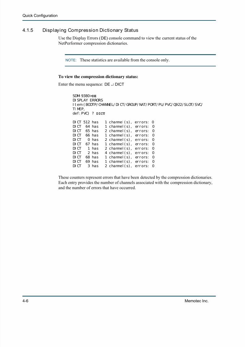
4.1.5 Displaying Compression Dictionary Status
Use the Display Errors ( DE ) console command to view the current status of the NetPerformer compression dictionaries.
NOTE: These statistics are available from the console only.
To view the compression dictionary status:
Enter the menu sequence: DE DICT
SDM- 9380> DEDI SPLAY ERRORSI t em ( BOOTP/ CHANNEL/ DI CT/ GROUP/ NAT/ PORT/ PU/ PVC/ Q922/ SLOT/ SVC/
TI MEP,def : PVC) ? DICT
DI CT 512 has 1 channel ( s) , er r ors: 0DI CT 64 has 1 channel ( s) , er r ors: 0DI CT 65 has 2 channel ( s) , er r ors: 0DI CT 66 has 1 channel ( s) , er r ors: 0DI CT 0 has 2 channel ( s) , err ors: 0DI CT 67 has 1 channel ( s) , er r ors: 0DI CT 1 has 2 channel ( s) , err ors: 0DI CT 2 has 4 channel ( s) , err ors: 0DI CT 68 has 1 channel ( s) , er r ors: 0DI CT 69 has 1 channel ( s) , er r ors: 0DI CT 3 has 2 channel ( s) , err ors: 0
These counters represent errors that have been detected by the compression dictionaries.
Each entry provides the number of channels associated with the compression dictionary,and the number of errors that have occurred.

7/23/2019 04 Quick Configuration
http://slidepdf.com/reader/full/04-quick-configuration 57/102
Global Functions
Memotec Inc. 4-7
4.2 Displaying and Setting the System TimeIt is extremely important to maintain the proper date and time on the NetPerformer unit toavoid file management problems, particularly when uploading a new firmware version.
Caution: If the system date and time are incorrect, a new firmware version may
be interpreted as an older version.
4.2.1 Displaying the Time
To view the current system date and time, use the Display Time ( DT) command.
To view the current system time on the NetPerformer unit:
Enter DT at the main console prompt.
SDM- 9230> DTDI SPLAY TI ME
Ti me> THU 2003/ 09/ 04 16: 24: 04
4.2.2 Setting the Time
To change the system date and time, use the Set Time ( ST ) command.
To set the system time:
1. Enter ST at the main console prompt.
Figure 4-5: DT Path on the CLI Tree
Figure 4-6: ST Path on the CLI Tree

7/23/2019 04 Quick Configuration
http://slidepdf.com/reader/full/04-quick-configuration 58/102
Quick Configuration
4-8 Memotec Inc.
2. Enter the new value of each parameter after the parameter prompt.
3. To confirm the time change, enter YES at the Accept new time? prompt.
SDM- 9230> STSET TI MECLOCK> Year ( 1992- 2030, def : 2003) ?CLOCK> Mont h ( 1- 12, def : 9) ? 10CLOCK> Day of t he mont h ( 1- 31, def : 4) ? 15CLOCK> Day of t he week ( def : WEDNESDAY) ?CLOCK> Hour ( 0- 23, def : 16) ? 17CLOCK> Mi nut e ( 0- 59, def : 24) ? 09CLOCK> Second ( 0- 59, def : 24) ?
Ti me> WED 2003/ 10/ 15 17: 09: 24
Accept new t i me? ( NO/ YES, def : YES) ? YES
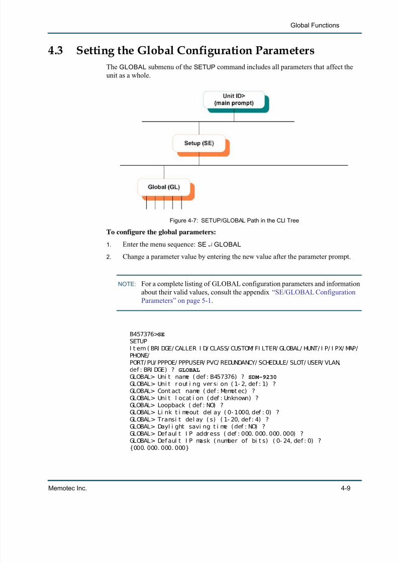
7/23/2019 04 Quick Configuration
http://slidepdf.com/reader/full/04-quick-configuration 59/102
Global Functions
Memotec Inc. 4-9
4.3 Setting the Global Configuration ParametersThe GLOBAL submenu of the SETUP command includes all parameters that affect theunit as a whole.
To configure the global parameters:
1. Enter the menu sequence: SE GLOBAL
2. Change a parameter value by entering the new value after the parameter prompt.
NOTE: For a complete listing of GLOBAL configuration parameters and informationabout their valid values, consult the appendix “SE/GLOBAL ConfigurationParameters” on page 5-1 .
B457376> SESETUPI t em ( BRI DGE/ CALLER I D/ CLASS/ CUSTOM/ FI LTER/ GLOBAL/ HUNT/ I P/ I PX/ MAP/PHONE/PORT/ PU/ PPPOE/ PPPUSER/ PVC/ REDUNDANCY/ SCHEDULE/ SLOT/ USER/ VLAN,def : BRI DGE) ? GLOBALGLOBAL> Uni t name ( def : B457376) ? SDM-9230GLOBAL> Uni t r out i ng ver si on ( 1- 2, def : 1) ?GLOBAL> Cont act name ( def : Memot ec) ?GLOBAL> Uni t l ocat i on ( def : Unknown) ?GLOBAL> Loopback ( def : NO) ?GLOBAL> Li nk t i meout del ay ( 0- 1000, def : 0) ?GLOBAL> Transi t del ay ( s) ( 1- 20, def : 4) ?GLOBAL> Dayl i ght savi ng t i me (def : NO) ?GLOBAL> Def aul t I P addr ess ( def : 000. 000. 000. 000) ?GLOBAL> Def aul t I P mask ( number of bi t s) ( 0- 24, def : 0) ?{000. 000. 000. 000}
Figure 4-7: SETUP/GLOBAL Path in the CLI Tree
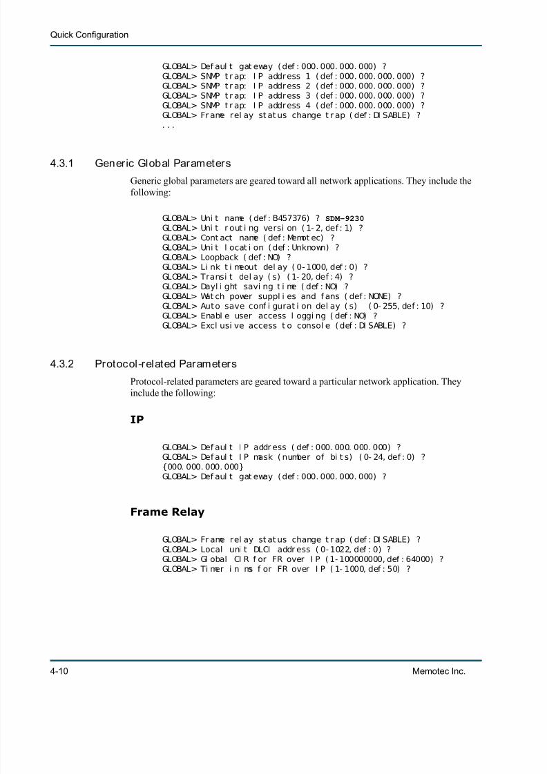
7/23/2019 04 Quick Configuration
http://slidepdf.com/reader/full/04-quick-configuration 60/102
Quick Configuration
4-10 Memotec Inc.
GLOBAL> Def aul t gat eway ( def : 000. 000. 000. 000) ?GLOBAL> SNMP t r ap: I P address 1 ( def : 000. 000. 000. 000) ?GLOBAL> SNMP t r ap: I P address 2 ( def : 000. 000. 000. 000) ?GLOBAL> SNMP t r ap: I P address 3 ( def : 000. 000. 000. 000) ?GLOBAL> SNMP t r ap: I P address 4 ( def : 000. 000. 000. 000) ?GLOBAL> Fr ame rel ay st at us change t r ap ( def : DI SABLE) ?. . .
4.3.1 Generic Global Parameters
Generic global parameters are geared toward all network applications. They include thefollowing:
GLOBAL> Uni t name ( def : B457376) ? SDM-9230GLOBAL> Uni t r out i ng versi on ( 1- 2, def : 1) ?GLOBAL> Cont act name ( def : Memot ec) ?GLOBAL> Uni t l ocat i on ( def : Unknown) ?GLOBAL> Loopback ( def : NO) ?
GLOBAL> Li nk t i meout del ay ( 0- 1000, def : 0) ?GLOBAL> Transi t del ay ( s) ( 1- 20, def : 4) ?GLOBAL> Dayl i ght savi ng t i me ( def : NO) ?GLOBAL> Wat ch power suppl i es and f ans ( def : NONE) ?GLOBAL> Aut o save conf i gurat i on del ay ( s) ( 0- 255, def : 10) ?GLOBAL> Enabl e user access l oggi ng ( def : NO) ?GLOBAL> Excl usi ve access t o consol e ( def : DI SABLE) ?
4.3.2 Protocol-related Parameters
Protocol-related parameters are geared toward a particular network application. Theyinclude the following:
IP
GLOBAL> Def aul t I P addr ess ( def : 000. 000. 000. 000) ?GLOBAL> Def aul t I P mask ( number of bi t s) ( 0- 24, def : 0) ?{000. 000. 000. 000}GLOBAL> Def aul t gat eway ( def : 000. 000. 000. 000) ?
Frame Relay
GLOBAL> Fr ame rel ay st at us change t r ap ( def : DI SABLE) ?GLOBAL> Local uni t DLCI addr ess ( 0- 1022, def : 0) ?GLOBAL> Gl obal CI R f or FR over I P ( 1- 100000000, def : 64000) ?GLOBAL> Ti mer i n ms f or FR over I P ( 1- 1000, def : 50) ?

7/23/2019 04 Quick Configuration
http://slidepdf.com/reader/full/04-quick-configuration 61/102
Global Functions
Memotec Inc. 4-11
SNMP
GLOBAL> SNMP t r ap: I P address 1 ( def : 000. 000. 000. 000) ?GLOBAL> SNMP t r ap: I P address 2 ( def : 000. 000. 000. 000) ?GLOBAL> SNMP t r ap: I P address 3 ( def : 000. 000. 000. 000) ?GLOBAL> SNMP t r ap: I P address 4 ( def : 000. 000. 000. 000) ?
Voice
GLOBAL> Count r y code ( 0- 9999, def : 1) ?GLOBAL> J i t t er buf f er ( ms) ( 0- 200, i nc: 10, def : 170) ?GLOBAL> Enabl e voi ce/ f ax l og ( def : YES) ?GLOBAL> Di al t i mer ( s) ( 0- 10, def : 4) ?GLOBAL> Hi gh pr i ori t y voi ce cl ass ( def : YES) ? NOGLOBAL> Voi ce cl ass ( 1- 8, def : 4) ?GLOBAL> Max number of voi ce channel s over I P ( 0- 10000, def : 10000) ?GLOBAL> Del ay gener at ed by a comma ( ms) ( 250- 4000, i nc: 250, def : 250)?GLOBAL> I SDN G4 Fax PCM swi t chi ng enabl e ( def : NO) ?GLOBAL> Enabl e VTR ( Voi ce Tr af f i c Rout i ng) ( def : NO) ?GLOBAL> Enabl e Domai n Di al i ng ( def : YES) ?GLOBAL> Enabl e hunt f or war di ng ( def : YES) ?
4.3.3 Sett ing the Unit Name
The Unit Name is used to:
• Distinguish one NetPerformer unit from another in the same network
• Identify which unit the console is currently accessing, through the main console prompt
• Label entries in the PowerCell routing table, displayed with the Display Destina-tions ( DD) command
• Provide valid values for configuring the Remote Unit Name for a WAN ( PVCR )connection.
To set the Unit Name :
1. Enter the menu sequence: SE GLOBAL .
2. At the Unit name parameter prompt, enter a unique name for this NetPerformer unit.
You can choose whatever naming convention you like. By convention, the Unit Name is the fully-qualified domain name for this node.
Caution: You must specify a unique Unit name for each NetPerformer inthe network. WAN (PVCR) connections will not work if two units have the
same name.
NOTE: The default Unit name is the burned-in product serial number, which guaran-tees unique naming when you power up the unit for the first time.

7/23/2019 04 Quick Configuration
http://slidepdf.com/reader/full/04-quick-configuration 62/102
Quick Configuration
4-12 Memotec Inc.
4.3.4 Setting the Unit Routing Version
The Unit Routing Version determines how the PowerCell routing table is managed:
• With Unit Routing Version 1, each unit name takes up one entry in the routingtable.
• With Unit Routing Version 2, units can be assigned to a common group name ,and require only one entry in the routing table per group.
Caution: The Unit Routing Version must be the same throughout the entirenetwork.
To set the Unit Routing Version :
1. Enter the menu sequence: SE GLOBAL
2. At the Unit routing version parameter prompt, select:
• 1: If any NetPerformers in the network are running Unit Routing Version 1 .This is the version used in all NetPerformer firmware releases earlier thanV6.7.0.
• 2: If all NetPerformers in the network are running Unit Routing Version 2 ,which is used in V6.7.0 and higher.

7/23/2019 04 Quick Configuration
http://slidepdf.com/reader/full/04-quick-configuration 63/102
5
Memotec Inc. 5-1
SE/GLOBAL Configuration Parameters

7/23/2019 04 Quick Configuration
http://slidepdf.com/reader/full/04-quick-configuration 64/102
Quick Configuration
5-2 Memotec Inc.
5.1 About the GLOBAL submenuThe GLOBAL submenu of the SETUP console command includes all parameters thataffect the unit as a whole. If you are using SNMP, all global configuration variables aregrouped under the npsys category.
To configure the global parameters from the console:
• Enter the menu sequence: SE GLOBAL .
• Change the global parameters from their default values, if desired, following theexamples below.
Console SNMP Text-based Config
SE/GLOBAL npsys (category) npsys (heading)

7/23/2019 04 Quick Configuration
http://slidepdf.com/reader/full/04-quick-configuration 65/102
SE/GLOBAL Configuration Parameters
Memotec Inc. 5-3
5.2 Standalone Base ProductB457376> SESETUPI t em ( BRI DGE/ CALLER I D/ CLASS/ CUSTOM/ FI LTER/ GLOBAL/ HUNT/ I P/ I PX/ MAP/PHONE/PORT/ PU/ PPPOE/ PPPUSER/ PVC/ REDUNDANCY/ SCHEDULE/ SLOT/ USER/ VLAN,def : BRI DGE) ? GLOBALGLOBAL> Uni t name ( def : B457376) ? SDM-9230GLOBAL> Uni t r out i ng versi on ( 1- 2, def : 1) ?GLOBAL> Cont act name ( def : Memot ec) ?GLOBAL> Uni t l ocat i on ( def : Unknown) ?GLOBAL> Loopback ( def : NO) ?GLOBAL> Li nk t i meout del ay ( 0- 1000, def : 0) ?GLOBAL> Transi t del ay ( s) ( 1- 20, def : 4) ?GLOBAL> Dayl i ght savi ng t i me ( def : NO) ?GLOBAL> Def aul t I P addr ess ( def : 000. 000. 000. 000) ?GLOBAL> Def aul t I P mask ( number of bi t s) ( 0- 24, def : 0) ?{000. 000. 000. 000}GLOBAL> Def aul t gat eway ( def : 000. 000. 000. 000) ?GLOBAL> SNMP t r ap: I P address 1 ( def : 000. 000. 000. 000) ?GLOBAL> SNMP t r ap: I P address 2 ( def : 000. 000. 000. 000) ?GLOBAL> SNMP t r ap: I P address 3 ( def : 000. 000. 000. 000) ?GLOBAL> SNMP t r ap: I P address 4 ( def : 000. 000. 000. 000) ?GLOBAL> Fr ame rel ay st at us change t r ap ( def : DI SABLE) ?GLOBAL> Wat ch power suppl i es and f ans ( def : NONE) ?GLOBAL> Local uni t DLCI addr ess ( 0- 1022, def : 0) ?GLOBAL> Ext ensi on number ( no. of di gi t s) ( 2- 4, def : 3) ?GLOBAL> Count r y code ( 0- 9999, def : 1) ?GLOBAL> J i t t er buf f er ( ms) ( 0- 200, i nc: 10, def : 170) ?GLOBAL> Enabl e voi ce/ f ax l og ( def : YES) ?GLOBAL> Di al t i mer ( s) ( 0- 10, def : 4) ?GLOBAL> Hi gh pr i or i t y voi ce cl ass ( def : YES) ?GLOBAL> Gl obal CI R f or FR over I P ( 1- 100000000, def : 64000) ?GLOBAL> Ti mer i n ms f or FR over I P ( 1- 1000, def : 50) ?GLOBAL> Max number of voi ce channel s over I P ( 0- 10000, def : 10000) ?GLOBAL> Del ay generat ed by a comma ( ms) ( 250- 4000, i nc: 250, def : 250) ?GLOBAL> I SDN G4 Fax PCM swi t chi ng enabl e ( def : NO) ?GLOBAL> Aut o save conf i gurat i on del ay ( s) ( 0- 255, def : 10) ?GLOBAL> Enabl e VTR ( Voi ce Tr af f i c Rout i ng) ( def : NO) ?GLOBAL> Enabl e Domai n Di al i ng ( def : YES) ?GLOBAL> Enabl e hunt f or war di ng ( def : YES) ?GLOBAL> Enabl e user access l oggi ng ( def : NO) ?GLOBAL> Excl usi ve access t o consol e ( def : DI SABLE) ?

7/23/2019 04 Quick Configuration
http://slidepdf.com/reader/full/04-quick-configuration 66/102
Quick Configuration
5-4 Memotec Inc.
5.2.1 Unit name
The name of the NetPerformer unit. By convention, this is the node’s fully-qualifieddomain name.
The Unit name is used when accessing the unit for configuration and management purposes, and is entered in the routing table of network destinations reached using PVCRlinks. On the console, the current Unit name appears at the beginning of each commandline.
Caution: You must specify a unique Unit name for each NetPerformer in thenetwork. WAN (PVCR) connections will not work if two units have the samename. The default Unit name is the burned-in product serial number, whichguarantees unique naming when you configure the unit for the first time.
You can choose any naming convention you like. For example, use the city or company
name where the NetPerformer is located. We suggest that you name each unit according toits site and sequence. For example, if you have three NetPerformers located at a singlesite, you could name them BOSTON-1 , BOSTON-2 and BOSTON-3 .
5.2.2 Unit routing version
The routing version to be used on this unit. With the default Version 1 routing protocol,each unit name takes up one entry in the routing table. With Version 2 units can beassigned to a common group name, and require only one entry in the routing table pergroup of units.
• Set the Unit routing version to 1 if any NetPerformers in the network are runningUnit Routing Version 1. This is the version used in all NetPerformer softwarereleases earlier than V6.7.0.
• Set the Unit routing version to 2 if all NetPerformers are running Unit RoutingVersion 2, which is used in software release 6.7.0 and higher.
Caution: Each NetPerformer unit can be configured to run either routing version.However, the Unit routing version must be the same throughout the entire network.
Console SNMP Text-based Config
Unit name npsysName [npsys] Name
Values: Maximum 32-character alphanumeric string
Default: The burned-in product serial number
Console SNMP Text-based Config
Unit routing version npsysUnitRoutingVersion [npsys] UnitRoutingVer-
sion
Values: 1, 2
Default: 1

7/23/2019 04 Quick Configuration
http://slidepdf.com/reader/full/04-quick-configuration 67/102
SE/GLOBAL Configuration Parameters
Memotec Inc. 5-5
5.2.3 Contact name
The name or telephone number of a contact person for this NetPerformer unit. This parameter is required for information purposes only.
5.2.4 Unit location
The physical location of this NetPerformer unit. For example, you could define the Unitlocation as Telephone clos et, 3rd f loor. This parameter is required for information
purposes only.
5.2.5 Loopback
Control of loopback on the WAN links (PVCR protocol). The NetPerformer softwaredetects the presence of a loopback condition on any WAN link. The Loopback parameterdetermines whether loopback on any link is accepted ( YES ) or not accepted ( NO ).
• Set Loopback to YES to accept loopback on WAN links. This is required for test-ing purposes only.
• Setting Loopback to NO to prevent the NetPerformer from using a link that has been placed in loopback mode either temporarily or accidentally.
5.2.6 Link timeout delay
Console SNMP Text-based Config
Contact name npsysContact [npsys] Contact
Values: Maximum 32-character string; A-Z , 0-9 , . (period), , (comma),(space), - (hyphen)
Default: Memotec
Console SNMP Text-based Config
Unit location npsysLocation [npsys] Location
Values: Maximum 32-character string; A-Z , 0-9 , . (period), , (comma),(space), - (hyphen)
Default: Unknown
Console SNMP Text-based Config
Loopback npsysAcceptLoop [npsys] AcceptLoop
Values: YES, NO
Default: NO
Console SNMP Text-based Config
Link timeout delay npsysLinkTimeout-s [npsys] LinkTimeout-s
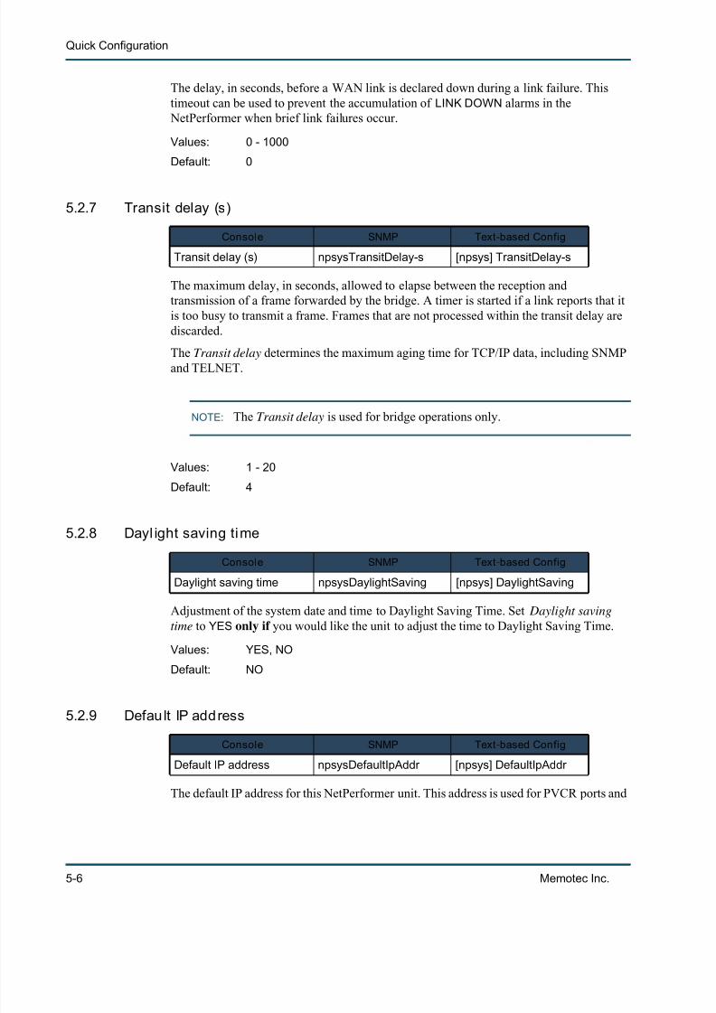
7/23/2019 04 Quick Configuration
http://slidepdf.com/reader/full/04-quick-configuration 68/102
Quick Configuration
5-6 Memotec Inc.
The delay, in seconds, before a WAN link is declared down during a link failure. Thistimeout can be used to prevent the accumulation of LINK DOWN alarms in the
NetPerformer when brief link failures occur.
5.2.7 Transit delay (s)
The maximum delay, in seconds, allowed to elapse between the reception andtransmission of a frame forwarded by the bridge. A timer is started if a link reports that itis too busy to transmit a frame. Frames that are not processed within the transit delay arediscarded.
The Transit delay determines the maximum aging time for TCP/IP data, including SNMPand TELNET.
NOTE: The Transit delay is used for bridge operations only.
5.2.8 Dayl ight saving time
Adjustment of the system date and time to Daylight Saving Time. Set Daylight savingtime to YES only if you would like the unit to adjust the time to Daylight Saving Time.
5.2.9 Defau lt IP address
The default IP address for this NetPerformer unit. This address is used for PVCR ports and
Values: 0 - 1000
Default: 0
Console SNMP Text-based Config
Transit delay (s) npsysTransitDelay-s [npsys] TransitDelay-s
Values: 1 - 20
Default: 4
Console SNMP Text-based Config
Daylight saving time npsysDaylightSaving [npsys] DaylightSaving
Values: YES, NO
Default: NO
Console SNMP Text-based Config
Default IP address npsysDefaultIpAddr [npsys] DefaultIpAddr
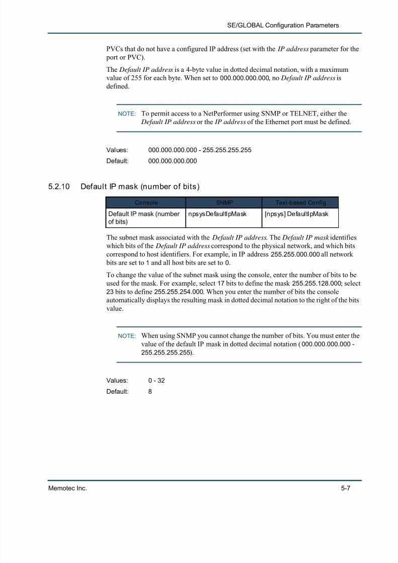
7/23/2019 04 Quick Configuration
http://slidepdf.com/reader/full/04-quick-configuration 69/102
SE/GLOBAL Configuration Parameters
Memotec Inc. 5-7
PVCs that do not have a configured IP address (set with the IP address parameter for the port or PVC).
The Default IP address is a 4-byte value in dotted decimal notation, with a maximumvalue of 255 for each byte. When set to 000.000.000.000 , no Default IP address isdefined.
NOTE: To permit access to a NetPerformer using SNMP or TELNET, either the Default IP address or the IP address of the Ethernet port must be defined.
5.2.10 Default IP mask (number of bits)
The subnet mask associated with the Default IP address . The Default IP mask identifieswhich bits of the Default IP address correspond to the physical network, and which bitscorrespond to host identifiers. For example, in IP address 255.255.000.000 all network
bits are set to 1 and all host bits are set to 0 .
To change the value of the subnet mask using the console, enter the number of bits to beused for the mask. For example, select 17 bits to define the mask 255.255.128.000 ; select23 bits to define 255.255.254.000 . When you enter the number of bits the consoleautomatically displays the resulting mask in dotted decimal notation to the right of the bitsvalue.
NOTE: When using SNMP you cannot change the number of bits. You must enter thevalue of the default IP mask in dotted decimal notation ( 000.000.000.000 -255.255.255.255 ).
Values: 000.000.000.000 - 255.255.255.255
Default: 000.000.000.000
Console SNMP Text-based Config
Default IP mask (numberof bits)
npsysDefaultIpMask [npsys] DefaultIpMask
Values: 0 - 32
Default: 8

7/23/2019 04 Quick Configuration
http://slidepdf.com/reader/full/04-quick-configuration 70/102
Quick Configuration
5-8 Memotec Inc.
5.2.11 Default gateway
The default gateway IP address that the NetPerformer will use to send frames to a deviceon another network if there is no valid gateway entry in the routing table.
The Default gateway is a 4-byte value in dotted decimal notation, with a maximum valueof 255 for each byte.
• Enter the IP address of the gateway that should be used when a destination isunknown. All frames with unknown destinations are sent to this gateway.
• When this parameter is set to 000.000.000.000 , no default gateway is defined onthe NetPerformer. All frames with unknown destinations will be discarded.
5.2.12 SNMP trap: IP address 1,2,3,4
The IP addresses available to SNMP as the destination for traps. Traps are sent only to
those SNMP managers that are specified with one of these IP addresses. Up to 4 distinct IPaddresses can be defined.
Each SNMP trap IP address is a 4-byte value in dotted decimal notation, with a maximumvalue of 255 for each byte. Define the SNMP trap IP address with the address of theSNMP management device that should receive all traps occurring in the network.
Caution: SNMP will send its traps to the configured destination(s) only. If you donot define any SNMP Trap IP Addresses (all 4 IP addresses are left at the defaultvalue, 000.000.000.000 ) no managers on the LAN will receive any traps.
Console SNMP Text-based Config
Default gateway npsysDefaultGateway [npsys] DefaultGateway
Values: 000.000.000.000 - 255.255.255.255
Default: 000.000.000.000
Console SNMP Text-based Config
SNMP trap: IP address #1SNMP trap: IP address #2SNMP trap: IP address #3SNMP trap: IP address #4
npsysSnmpTrapIpAddr1npsysSnmpTrapIpAddr2npsysSnmpTrapIpAddr3npsysSnmpTrapIpAddr4
[npsys]SnmpTrapIpAddr1SnmpTrapIpAddr2SnmpTrapIpAddr3SnmpTrapIpAddr4
Values: 000.000.000.000 - 255.255.255.255
Default: 000.000.000.000
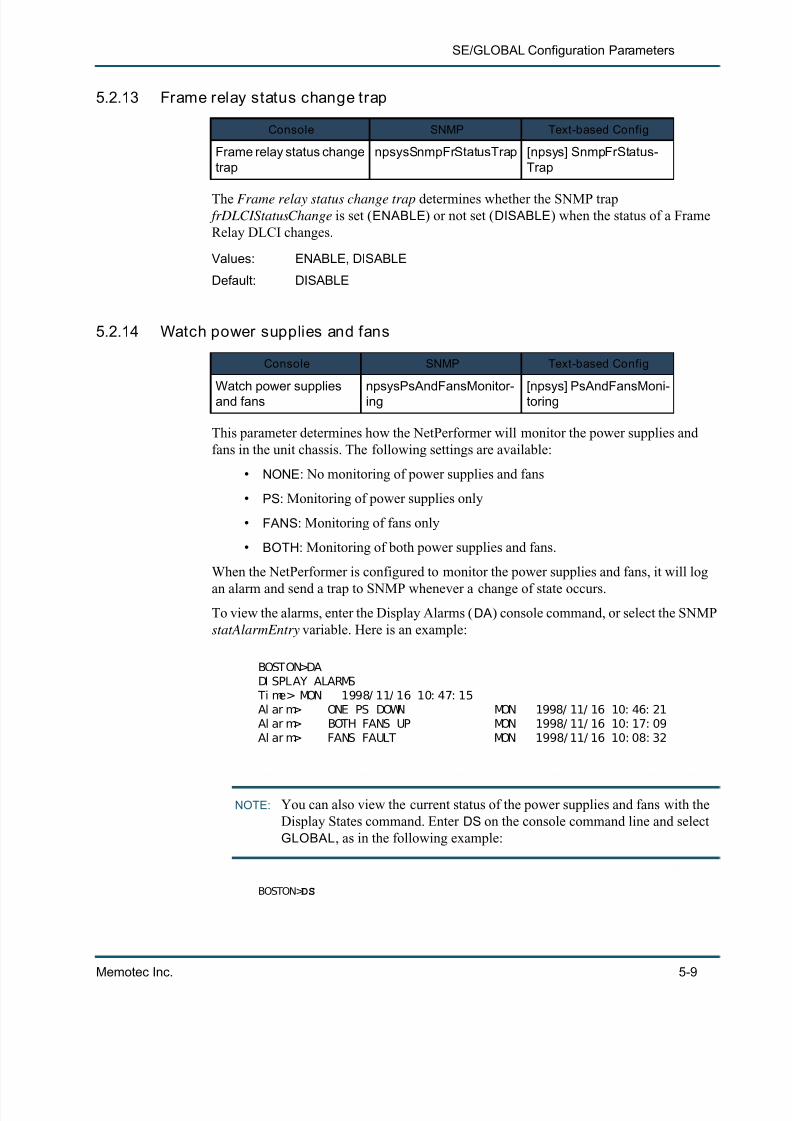
7/23/2019 04 Quick Configuration
http://slidepdf.com/reader/full/04-quick-configuration 71/102
SE/GLOBAL Configuration Parameters
Memotec Inc. 5-9
5.2.13 Frame relay status change trap
The Frame relay status change trap determines whether the SNMP trap frDLCIStatusChange is set ( ENABLE ) or not set ( DISABLE ) when the status of a FrameRelay DLCI changes.
5.2.14 Watch power supplies and fans
This parameter determines how the NetPerformer will monitor the power supplies andfans in the unit chassis. The following settings are available:
• NONE : No monitoring of power supplies and fans
• PS : Monitoring of power supplies only
• FANS : Monitoring of fans only
• BOTH : Monitoring of both power supplies and fans.
When the NetPerformer is configured to monitor the power supplies and fans, it will log
an alarm and send a trap to SNMP whenever a change of state occurs.To view the alarms, enter the Display Alarms ( DA) console command, or select the SNMPstatAlarmEntry variable. Here is an example:
BOSTON>DADI SPLAY ALARMS
Ti me> MON 1998/ 11/ 16 10: 47: 15Al ar m> ONE PS DOWN MON 1998/ 11/ 16 10: 46: 21Al ar m> BOTH FANS UP MON 1998/ 11/ 16 10: 17: 09Al ar m> FANS FAULT MON 1998/ 11/ 16 10: 08: 32
NOTE: You can also view the current status of the power supplies and fans with theDisplay States command. Enter DS on the console command line and selectGLOBAL , as in the following example:
BOSTON> DS
Console SNMP Text-based Config
Frame relay status changetrap
npsysSnmpFrStatusTrap [npsys] SnmpFrStatus-Trap
Values: ENABLE, DISABLE
Default: DISABLE
Console SNMP Text-based Config
Watch power suppliesand fans npsysPsAndFansMonitor-ing [npsys] PsAndFansMoni-toring
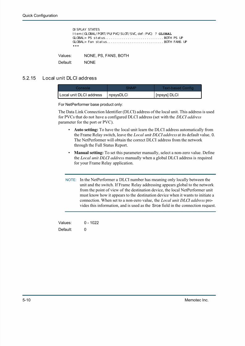
7/23/2019 04 Quick Configuration
http://slidepdf.com/reader/full/04-quick-configuration 72/102
Quick Configuration
5-10 Memotec Inc.
DI SPLAY STATESI t em ( GLOBAL/ PORT/ PU/ PVC/ SLOT/ SVC, def : PVC) ? GLOBALGLOBAL> PS s t at us . . . . . . . . . . . . . . . . . . . . . . . . . . . . . . . BOTH PS UPGLOBAL> Fan st at us . . . . . . . . . . . . . . . . . . . . . . . . . . . . . . BOTH FANS UP•••
5.2.15 Local unit DLCI address
For NetPerformer base product only:
The Data Link Connection Identifier (DLCI) address of the local unit. This address is usedfor PVCs that do not have a configured DLCI address (set with the DLCI address
parameter for the port or PVC).
• Auto setting: To have the local unit learn the DLCI address automatically fromthe Frame Relay switch, leave the Local unit DLCI address at its default value, 0 .The NetPerformer will obtain the correct DLCI address from the networkthrough the Full Status Report.
• Manual setting: To set this parameter manually, select a non-zero value. Definethe Local unit DLCI address manually when a global DLCI address is requiredfor your Frame Relay application.
NOTE:In the NetPerformer a DLCI number has meaning only locally between theunit and the switch. If Frame Relay addressing appears global to the networkfrom the point of view of the destination device, the local NetPerformer unitmust know how it appears to the destination device when it wants to initiate aconnection. When set to a non-zero value, the Local unit DLCI address pro-vides this information, and is used as the Srce field in the connection request.
Values: NONE, PS, FANS, BOTH
Default: NONE
Console SNMP Text-based Config
Local unit DLCI address npsysDLCI [npsys] DLCI
Values: 0 - 1022
Default: 0

7/23/2019 04 Quick Configuration
http://slidepdf.com/reader/full/04-quick-configuration 73/102

7/23/2019 04 Quick Configuration
http://slidepdf.com/reader/full/04-quick-configuration 74/102
Quick Configuration
5-12 Memotec Inc.
fax connection.
If packets arrive at inconsistent intervals, voice quality may be choppy on a voiceconnection. When the Jitter buffer parameter is set to higher values, the end-to-end delayincreases, but voice quality remains smooth. Lower values decrease end-to-end delay, butmay produce choppy voice quality.
Set the Jitter buffer to 0 to enable dynamic jitter buffer, where the DSP determines the jitter in the network by calculating the time between packets. The DSP performs thiscalculation on startup and every time the jitter buffer overflows or under-flows.
5.2.19 Enable voice/fax log
For NetPerformer base product only:
This parameter determines whether the voice/fax log is enabled ( YES ) or disabled ( NO ).Set Enable voice/fax log to YES if you require a log of all voice/fax calls completed fromthis unit. This can be useful for accounting purposes.
The voice/fax log can be viewed at the console with the Display Log ( DL) command. Forfurther information, refer to the Monitoring and Statistics module of this document series.
5.2.20 Dial timer (s )
The amount of time, in seconds, that the application will wait for a digit of the speed dialnumber or the extended digits when attempting to set up a voice/fax connection. The Dialtimer specifies the amount of time the system should wait for a response to a Call Connector Call Clear requests.
Set this parameter to the maximum length of time required to dial a speed dial number.The NetPerformer determines that a dialing sequence is completed when the Dial timer expires or when the user terminates dialing with the pound sign ( #).
When it is set to a non-zero value, the Dial timer can also be used to forward digits:
• The Dial timer is applied on the Extended digits to forward parameter
Values: 0 - 200 (in increments of 10 ms)
Default: 170
Console SNMP Text-based Config
Enable voice/fax log npsysVoiceLog [npsys] VoiceLog
Values: YES, NO
Default: YES
Console SNMP Text-based Config
Dial timer (s) npsysDialTimer [npsys] DialTimer
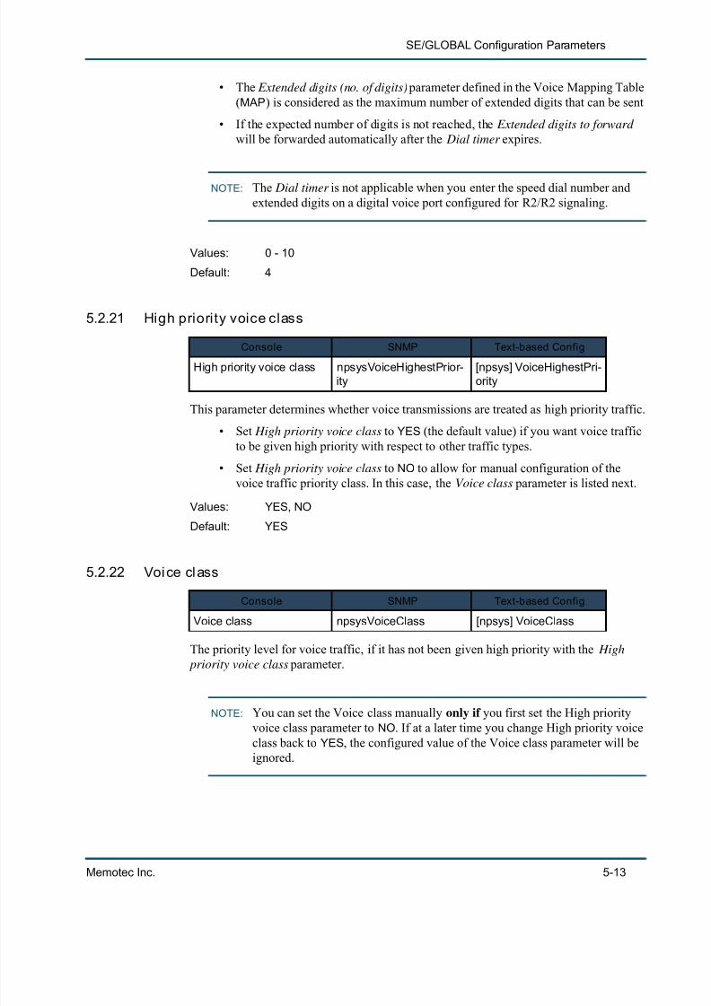
7/23/2019 04 Quick Configuration
http://slidepdf.com/reader/full/04-quick-configuration 75/102
SE/GLOBAL Configuration Parameters
Memotec Inc. 5-13
• The Extended digits (no. of digits) parameter defined in the Voice Mapping Table(MAP ) is considered as the maximum number of extended digits that can be sent
• If the expected number of digits is not reached, the Extended digits to forward will be forwarded automatically after the Dial timer expires.
NOTE: The Dial timer is not applicable when you enter the speed dial number andextended digits on a digital voice port configured for R2/R2 signaling.
5.2.21 High priority voice class
This parameter determines whether voice transmissions are treated as high priority traffic.
• Set High priority voice class to YES (the default value) if you want voice trafficto be given high priority with respect to other traffic types.
• Set High priority voice class to NO to allow for manual configuration of thevoice traffic priority class. In this case, the Voice class parameter is listed next.
5.2.22 Voice class
The priority level for voice traffic, if it has not been given high priority with the High priority voice class parameter.
NOTE: You can set the Voice class manually only if you first set the High priorityvoice class parameter to NO . If at a later time you change High priority voiceclass back to YES , the configured value of the Voice class parameter will beignored.
Values: 0 - 10
Default: 4
Console SNMP Text-based ConfigHigh priority voice class npsysVoiceHighestPrior-
ity[npsys] VoiceHighestPri-ority
Values: YES, NO
Default: YES
Console SNMP Text-based Config
Voice class npsysVoiceClass [npsys] VoiceClass
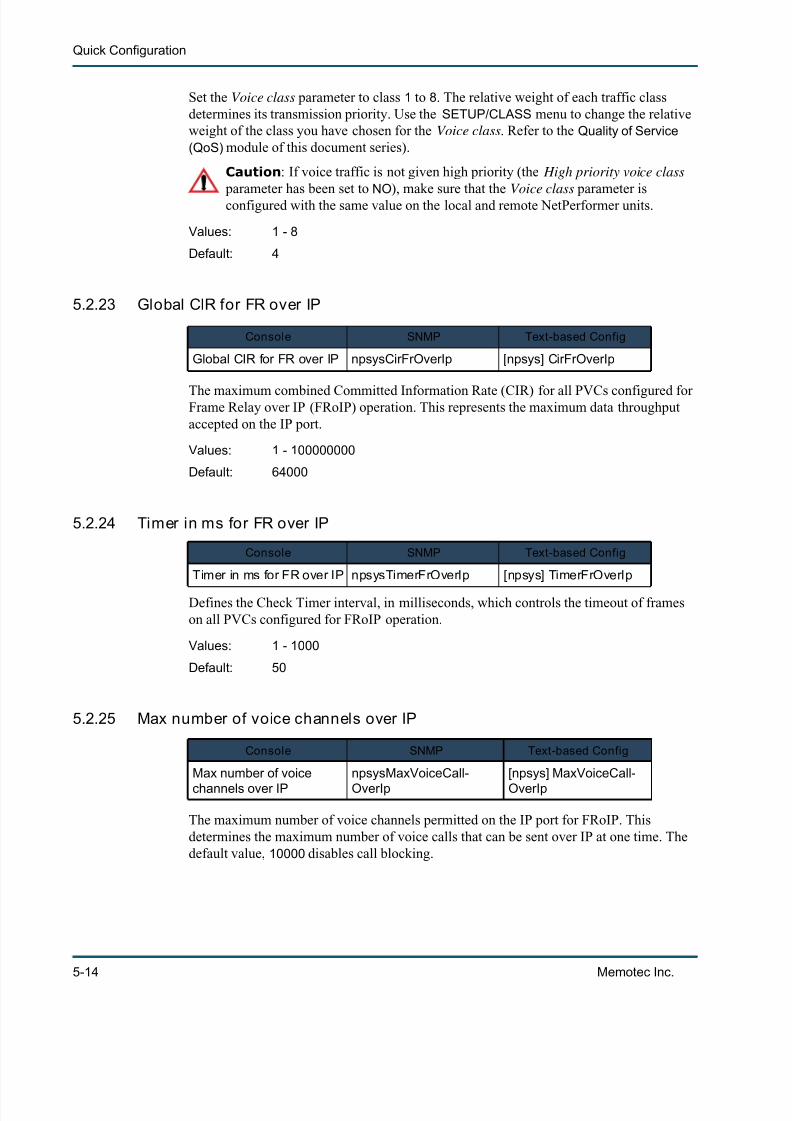
7/23/2019 04 Quick Configuration
http://slidepdf.com/reader/full/04-quick-configuration 76/102
Quick Configuration
5-14 Memotec Inc.
Set the Voice class parameter to class 1 to 8 . The relative weight of each traffic classdetermines its transmission priority. Use the SETUP/CLASS menu to change the relativeweight of the class you have chosen for the Voice class . Refer to the Quality of Service(QoS) module of this document series).
Caution : If voice traffic is not given high priority (the High priority voice class parameter has been set to NO ), make sure that the Voice class parameter isconfigured with the same value on the local and remote NetPerformer units.
5.2.23 Global CIR for FR over IP
The maximum combined Committed Information Rate (CIR) for all PVCs configured forFrame Relay over IP (FRoIP) operation. This represents the maximum data throughputaccepted on the IP port.
5.2.24 Timer in ms for FR over IP
Defines the Check Timer interval, in milliseconds, which controls the timeout of frameson all PVCs configured for FRoIP operation.
5.2.25 Max number of voice channels over IP
The maximum number of voice channels permitted on the IP port for FRoIP. Thisdetermines the maximum number of voice calls that can be sent over IP at one time. Thedefault value, 10000 disables call blocking.
Values: 1 - 8
Default: 4
Console SNMP Text-based Config
Global CIR for FR over IP npsysCirFrOverIp [npsys] CirFrOverIp
Values: 1 - 100000000
Default: 64000
Console SNMP Text-based Config
Timer in ms for FR over IP npsysTimerFrOverIp [npsys] TimerFrOverIp
Values: 1 - 1000
Default: 50
Console SNMP Text-based Config
Max number of voicechannels over IP
npsysMaxVoiceCall-OverIp
[npsys] MaxVoiceCall-OverIp

7/23/2019 04 Quick Configuration
http://slidepdf.com/reader/full/04-quick-configuration 77/102
SE/GLOBAL Configuration Parameters
Memotec Inc. 5-15
NOTE: Max number of voice channels over IP does not appear at the console whenthe NetPerformer is installed with the SIP VoIP licensed software option,since PowerCell voice is not supported in SIP mode.
5.2.26 Delay generated by a comma (ms)
The delay, in milliseconds, generated by a comma for voice dialing. The Signaling Engine pauses its dialing procedure for this length of time when a comma is encountered in thedigit stream.
5.2.27 ISDN G4 Fax PCM switching enable
Set ISDN G4 Fax PCM switching enable to YES to allow the NetPerformer to transportG4 fax messages. When the NetPerformer detects that an incoming ISDN call is a G4 faxmessage, it switches the traffic to a PCM64K voice channel.
If this parameter is set to NO , incoming G4 fax is ignored.
5.2.28 Auto save configuration delay (s)
The delay, in seconds, before the NetPerformer automatically saves the configuration file.This determines the interval at which automatic saving take place. If you reduce this
Values: 1 - 10000
Default: 10000
Console SNMP Text-based Config
Delay generated by acomma (ms)
npsysCommaDelay [npsys] CommaDelay
Values: 250 - 4000 (in increments of 250 ms)
Default: 250
Console SNMP Text-based Config
ISDN G4 Fax PCM switch-
ing enable
npsysSeClearPcm [npsys] SeClearPcm
Values: YES, NO
Default: NO
Console SNMP Text-based Config
Auto save configurationdelay (s)
npsysAutoSave-Delay [npsys] AutoSaveDelay
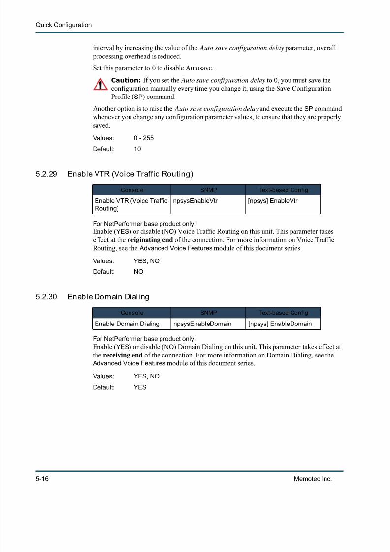
7/23/2019 04 Quick Configuration
http://slidepdf.com/reader/full/04-quick-configuration 78/102
Quick Configuration
5-16 Memotec Inc.
interval by increasing the value of the Auto save configuration delay parameter, overall processing overhead is reduced.
Set this parameter to 0 to disable Autosave.
Caution: If you set the Auto save configuration delay to 0 , you must save theconfiguration manually every time you change it, using the Save Configuration
Profile ( SP ) command.Another option is to raise the Auto save configuration delay and execute the SP commandwhenever you change any configuration parameter values, to ensure that they are properlysaved.
5.2.29 Enable VTR (Voice Traffic Routing)
For NetPerformer base product only:Enable ( YES ) or disable ( NO ) Voice Traffic Routing on this unit. This parameter takeseffect at the originating end of the connection. For more information on Voice TrafficRouting, see the Advanced Voice Features module of this document series.
5.2.30 Enable Domain Dialing
For NetPerformer base product only:Enable ( YES ) or disable ( NO ) Domain Dialing on this unit. This parameter takes effect atthe receiving end of the connection. For more information on Domain Dialing, see the
Advanced Voice Features module of this document series.
Values: 0 - 255
Default: 10
Console SNMP Text-based Config
Enable VTR (Voice TrafficRouting)
npsysEnableVtr [npsys] EnableVtr
Values: YES, NO
Default: NO
Console SNMP Text-based Config
Enable Domain Dialing npsysEnableDomain [npsys] EnableDomain
Values: YES, NO
Default: YES

7/23/2019 04 Quick Configuration
http://slidepdf.com/reader/full/04-quick-configuration 79/102
SE/GLOBAL Configuration Parameters
Memotec Inc. 5-17
5.2.31 Enable hunt forwarding
For NetPerformer base product only:Enable ( YES ) or disable ( NO ) Hunt Forwarding on this unit. This parameter takes effect atthe originating end of the connection. To use Hunt Forwarding in your network, you mustalso configure the parameters listed in the SETUP/HUNT menu. Refer to the AdvancedVoice Features module of this document series.
5.2.32 Enable user access logging
Enable ( YES ) or disable ( NO ) the logging of alarms when users access the unit via theconsole. To view the alarm log, execute the Display Alarms ( DA) command at the console.
5.2.33 Exclusive access to console
When this parameter is set to ENABLE , a second user cannot access the console anddisconnect the first user’s connection. The first user must disconnect the console to allowsomeone else to connect.
NOTE: Access timeouts are independent of the Exclusive access to console parame-ter . If you are using a dial-up or TELNET connection to the console, you will
be disconnected automatically after a period of inactivity, even if the Exclu-sive access to console parameter is enabled.
Console SNMP Text-based Config
Enable hunt forwarding npsysEnableHuntFwd [npsys] EnableHuntFwd
Values: YES, NO
Default: YES
Console SNMP Text-based Config
Enable user access log-ging
npsysUserAccessLog-ging
[npsys] UserAccessLog-ging
Values: YES, NO
Default: NO
Console SNMP Text-based Config
Exclusive access to con-sole
npsysExclusiveConsole [npsys] ExclusiveCon-sole
Values: ENABLE, DISABLE
Default: DISABLE

7/23/2019 04 Quick Configuration
http://slidepdf.com/reader/full/04-quick-configuration 80/102
Quick Configuration
5-18 Memotec Inc.
5.3 Rackmount ChassisSome additional global parameters appear at the console when configuring an SDM-9585card in the SDM-9500 rackmount chassis:
SDM- 9585> SESETUPI t em ( BRI DGE/ CALLER I D/ CLASS/ CUSTOM/ FI LTER/ GLOBAL/ I P/ I PX/ MAP/ PHONE/ PORT/PU/ PPPOE/ PPPUSER/ PVC/ REDUNDANCY/ SCHEDULE/ SI P/ SLOT/ USER/ VLAN,def : BRI DGE) ? GLOBALGLOBAL> Uni t name ( def : 9585- 3) ?GLOBAL> Uni t r out i ng ver si on ( 1- 2, def : 1) ?GLOBAL> Cont act name ( def : Memot ec) ?GLOBAL> Uni t l ocat i on ( def : Unknown) ?GLOBAL> Loopback ( def : NO) ?GLOBAL> Li nk t i meout del ay ( 0- 1000, def : 0) ?GLOBAL> Transi t del ay ( s) ( 1- 20, def : 4) ?GLOBAL> Dayl i ght savi ng t i me ( def : NO) ?GLOBAL> Def aul t gat eway ( def : 000. 000. 000. 000) ?GLOBAL> SNMP t r ap: I P address 1 ( def : 000. 000. 000. 000) ?GLOBAL> SNMP t r ap: I P address 2 ( def : 000. 000. 000. 000) ?GLOBAL> SNMP t r ap: I P address 3 ( def : 000. 000. 000. 000) ?GLOBAL> SNMP t r ap: I P address 4 ( def : 000. 000. 000. 000) ?GLOBAL> Fr ame rel ay st at us change t r ap ( def : DI SABLE) ?GLOBAL> Rack i d ( 0- 4, def : 1) ?GLOBAL> Wat ch power suppl i es and f ans ( def : NONE) ? BOTHGLOBAL> RI P ver si on f or backpl ane l i nks ( def : DI SABLE) ?GLOBAL> I PX RI P f or backpl ane l i nks ( def : ENABLE) ?GLOBAL> I PX SAP f or backpl ane l i nks ( def : ENABLE) ?
The additional parameters required to configure the SDM-9585 rackmount card includethe following:
5.3.1 Rack ID
The number of the rackmount chassis in which this NetPerformer card is found. This parameter is required when two or more rackmount chassis are daisy-chained together at asingle site. Set the Rack ID to 0 to indicates that this card is installed in the only rackmountchassis at this site.
You can use whatever numbering convention you like for the Rack ID . However, wesuggest that you number a daisy-chained series of rackmount chassis from top to bottomor from left to right, to ensure consistency at all sites in your network.
Console SNMP Text-based Config
Rack ID npsysRackId [npsys] RackId
Values: 0 - 4
Default: 1
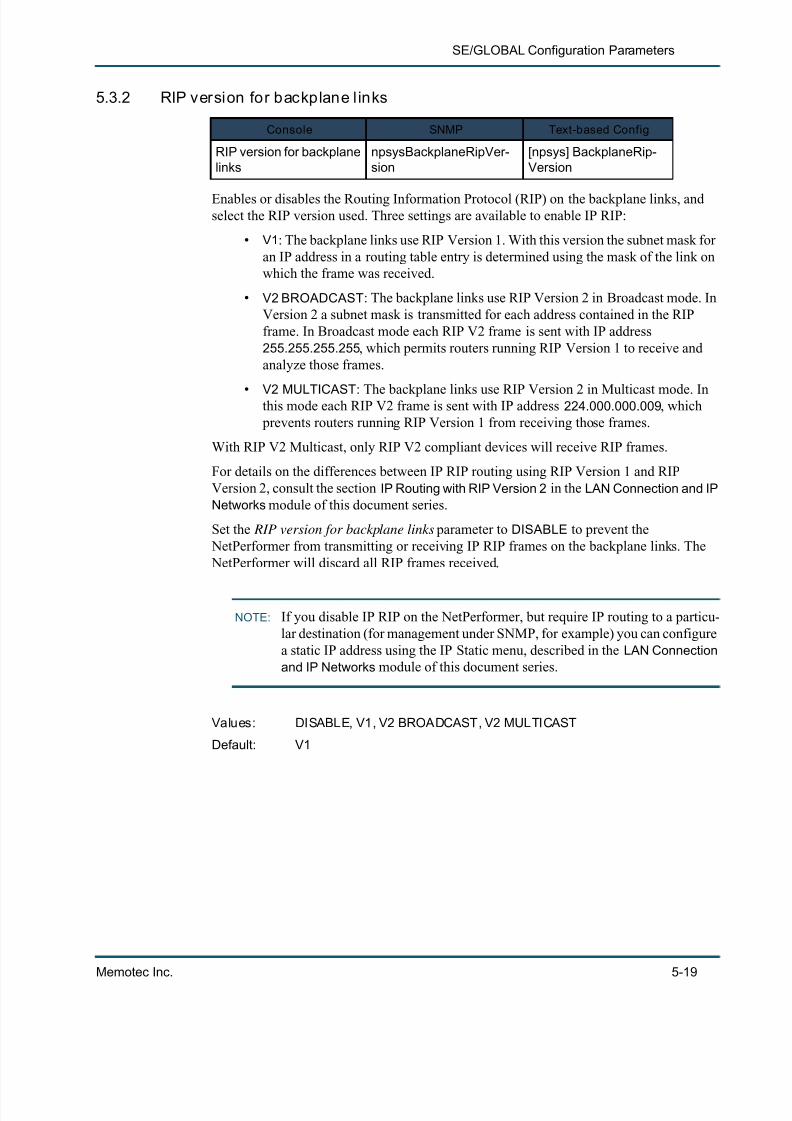
7/23/2019 04 Quick Configuration
http://slidepdf.com/reader/full/04-quick-configuration 81/102
SE/GLOBAL Configuration Parameters
Memotec Inc. 5-19
5.3.2 RIP version for backplane l inks
Enables or disables the Routing Information Protocol (RIP) on the backplane links, andselect the RIP version used. Three settings are available to enable IP RIP:
• V1: The backplane links use RIP Version 1. With this version the subnet mask foran IP address in a routing table entry is determined using the mask of the link onwhich the frame was received.
• V2 BROADCAST : The backplane links use RIP Version 2 in Broadcast mode. InVersion 2 a subnet mask is transmitted for each address contained in the RIPframe. In Broadcast mode each RIP V2 frame is sent with IP address255.255.255.255 , which permits routers running RIP Version 1 to receive andanalyze those frames.
• V2 MULTICAST : The backplane links use RIP Version 2 in Multicast mode. Inthis mode each RIP V2 frame is sent with IP address 224.000.000.009 , which prevents routers running RIP Version 1 from receiving those frames.
With RIP V2 Multicast, only RIP V2 compliant devices will receive RIP frames.
For details on the differences between IP RIP routing using RIP Version 1 and RIPVersion 2, consult the section IP Routing with RIP Version 2 in the LAN Connection and IPNetworks module of this document series.
Set the RIP version for backplane links parameter to DISABLE to prevent the NetPerformer from transmitting or receiving IP RIP frames on the backplane links. The NetPerformer will discard all RIP frames received.
NOTE: If you disable IP RIP on the NetPerformer, but require IP routing to a particu-lar destination (for management under SNMP, for example) you can configurea static IP address using the IP Static menu, described in the LAN Connectionand IP Networks module of this document series.
Console SNMP Text-based Config
RIP version for backplanelinks
npsysBackplaneRipVer-sion
[npsys] BackplaneRip-Version
Values: DISABLE, V1, V2 BROADCAST, V2 MULTICAST
Default: V1

7/23/2019 04 Quick Configuration
http://slidepdf.com/reader/full/04-quick-configuration 82/102
Quick Configuration
5-20 Memotec Inc.
5.3.3 IPX RIP for backplane l inks
Enables or disables IPX RIP on the backplane links of an SDM-9500 chassis. Set toENABLE to allow transmission of IPX RIP tables on the backplane links. When IPX RIP
for backplane links is set to DISABLE , you can configure two cards installed in the samechassis to be on two separate LAN segments.
If you change the value of this parameter the backplane link disconnects, then reconnects.
5.3.4 IP SAP for backplane l inks
Enables or disables IPX SAP on the backplane links of an SDM-9500 chassis. Set toENABLE to allow transmission of IPX SAP tables on the backplane links. When IPX SAP
for backplane links is set to DISABLE , you can configure two cards installed in the samechassis to be on two separate LAN segments.
If you change the value of this parameter the backplane link disconnects, then reconnects.
5.3.5 OSPF for backplane l inks
Enables or disables OSPF on the backplane links of an SDM-9500 chassis. Set toENABLE to allow transmission of OSPF tables on the backplane links. When OSPF for
backplane links is set to DISABLE , you can configure two cards installed in the samechassis to be on two separate LAN segments.
If you change the value of this parameter the backplane link disconnects, the reconnects.
Console SNMP Text-based Config
IPX RIP for back-plane links
npsysBackplaneIPXRipEn-able
[npsys] Back-planeIPXRipEnable
Values: ENABLE, DISABLE
Default: ENABLE
Console SNMP Text-based Config
IPX SAP for back-plane links
npsysBackplaneIPXSapEn-able
[npsys] BackplaneIPXS-apEnable
Values: ENABLE, DISABLE
Default: ENABLE
Console SNMP Text-based Config
OSPF for backplanelinks
npsysBackplaneOspfEn-able
[npsys] Backpla-neOspfEnable
Values: ENABLE, DISABLE
Default: ENABLE
7/23/2019 04 Quick Configuration
http://slidepdf.com/reader/full/04-quick-configuration 83/102
SE/GLOBAL Configuration Parameters
Memotec Inc. 5-21
5.4 SIP VoIP OptionOn the NetPerformer VoIP SIP option console the following Global parameters do notappear, as they are not required in a SIP-based application:
• Local unit DLCI address
• Extension number (no. of digits)
• Enable voice/fax log
• Max number of voice channels over IP
Similarly, the following parameters are not available on the NetPerformer SIP VoIPoption, as their functions are not supported under SIP:
• Enable VTR
• Enable Domain Dialing
• Enable hunt forwarding
5.5 ATM OptionWhen the ATM firmware option is loaded on the NetPerformer, three additional global
parameters are available to control how this option shares memory and configurationspace with other NetPerformer functions:
• Number of DSPs reserved for AAL1
• Number of data channels reserved
• Number of ATM AAL5 VCs reserved .
Details on these three ATM global parameters are provided in the ATM Option module ofthis document series.

7/23/2019 04 Quick Configuration
http://slidepdf.com/reader/full/04-quick-configuration 84/102
Quick Configuration
5-22 Memotec Inc.
7/23/2019 04 Quick Configuration
http://slidepdf.com/reader/full/04-quick-configuration 85/102
6
Memotec Inc. 6-1
Controlling Access to the NetPerformer
7/23/2019 04 Quick Configuration
http://slidepdf.com/reader/full/04-quick-configuration 86/102
Quick Configuration
6-2 Memotec Inc.
6.1 About Access Control
NOTE: Console access procedures are outlined in the Getting Started module ofthis document series.
The NetPerformer includes the following security features to help you control access tothe unit and its configuration:
• User profiles, which assign specific access privileges for each user (see “Defin-ing the User Profiles” on page 6-3 )
• FTP access restriction, to prevent unauthorized configuration file upload/down-load (see “Restricting FTP Access” on page 6-7 )
• Telnet access restriction, to prevent unauthorized Telnet access to the console(see “Restricting Telnet Access” on page 6-9 )
• Remote Authentication Dial-In User Service (RADIUS) for authentication ofconsole access. (see “Authentication Using RADIUS” on page 6-11 ).

7/23/2019 04 Quick Configuration
http://slidepdf.com/reader/full/04-quick-configuration 87/102
Controlling Access to the NetPerformer
Memotec Inc. 6-3
6.2 Defining the User ProfilesUser profiles assign username and password privileges to specific users. They areconfigured with the USER submenu of the SETUP console command. Up to 10 authorizedusers can be defined.
NOTE: If you do not define any user profiles, only the administrator login ( ADMIN )is available for access to the unit console.
Users can have either:
• Read/write access for configuring, managing and monitoring the unit ( FULL access), or
• Read-only access for monitoring the unit only ( MONITOR access).
Caution: To permit configuration of the unit, at least one user must bedefined with FULL access. By default, the administrator login is defined withFULL access.
To create a user profile:
Enter the menu sequence: SE USER .
SDM- 9230> SESETUPI t em ( BRI DGE/ CALLER I D/ CLASS/ CUSTOM/ FI LTER/ GLOBAL/ HUNT/ I P/ I PX/ MAP/PHONE/PORT/ PU/ PPPOE/ PPPUSER/ PVC/ REDUNDANCY/ SCHEDULE/ SLOT/ USER/ VLAN,def : BRI DGE) ? USER User pr of i l e number ( 1- 10, def : 1) ? 3USER 3> User Name ( def : ) ? JANUSER 3> Change passwor d (NO/ YES, def : NO) ? YES
Figure 6-1: SETUP/USER Path on the CLI Tree
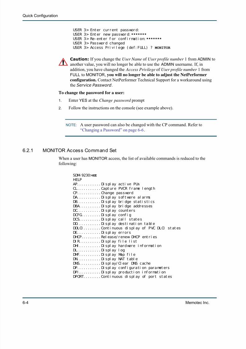
7/23/2019 04 Quick Configuration
http://slidepdf.com/reader/full/04-quick-configuration 88/102
Quick Configuration
6-4 Memotec Inc.
USER 3> Ent er cur r ent passwor d:USER 3> Ent er new passwor d: *******USER 3> Re- ent er f or conf i r mat i on: *******USER 3> Passwor d changedUSER 3> Access Pr i vi l ege ( def : FULL) ? MONITOR
Caution: If you change the User Name of User profile number 1 from ADMIN toanother value, you will no longer be able to use the ADMIN username. If, inaddition, you have changed the Access Privilege of User profile number 1 fromFULL to MONITOR , you will no longer be able to adjust the NetPerformerconfiguration. Contact NetPerformer Technical Support for a workaround usingthe Service Password .
To change the password for a user:
1. Enter YES at the Change password prompt
2. Follow the instructions on the console (see example above).
NOTE: A user password can also be changed with the CP command. Refer to“Changing a Password” on page 6-6 .
6.2.1 MONITOR Access Command Set
When a user has MONITOR access, the list of available commands is reduced to thefollowing:
SDM- 9230> HEHELPAP. . . . . . . . . . . Di s pl ay act i ve PUsCL. . . . . . . . . . . Capt ur e PVCR f r ame l engt hCP. . . . . . . . . . . Change passwordDA. . . . . . . . . . . Di spl ay sof t ware al armsDB. . . . . . . . . . . Di s pl ay br i dge st at i s t i csDBA. . . . . . . . . . Di spl ay br i dge addressesDC. . . . . . . . . . . Di s pl ay count er sDCFG. . . . . . . . . Di spl ay conf i gDCS. . . . . . . . . . Di s pl ay cal l s t at e sDD. . . . . . . . . . . Di s pl ay des t i nat i on t a bl eDDLCI . . . . . . . . Cont i nuous di spl ay of PVC DLCI st at esDE. . . . . . . . . . . Di s pl ay er r or sDHCP. . . . . . . . . Rel ease/ r enew DHCP ent r i esDI R. . . . . . . . . . Di spl ay f i l e l i stDHI . . . . . . . . . . Di spl ay hardware i nf ormat i onDL. . . . . . . . . . . Di spl ay l ogDMF. . . . . . . . . . Di s pl ay Map f i l eDN. . . . . . . . . . . Di spl ay NAT t abl eDNS. . . . . . . . . . Di spl ay/ Cl ear DNS cacheDP. . . . . . . . . . . Di spl ay conf i gura t i on paramet ersDPI . . . . . . . . . . Di spl ay pro duct i on i nf ormat i onDPORT. . . . . . . . Cont i nuous di spl ay of por t st at es

7/23/2019 04 Quick Configuration
http://slidepdf.com/reader/full/04-quick-configuration 89/102
Controlling Access to the NetPerformer
Memotec Inc. 6-5
DPU. . . . . . . . . . Cont i nuous di spl ay of PU s ta tesDPVC. . . . . . . . . Cont i nuous di spl ay of PVC st at esDR. . . . . . . . . . . Di s pl ay r out i ng t abl eDS. . . . . . . . . . . Di spl ay s t at esDSVC. . . . . . . . . Cont i nuous di spl ay of SVC st at esDT. . . . . . . . . . . Di spl ay t he cur r ent t i meDV. . . . . . . . . . . Di spl ay sof t ware vers i on
DX. . . . . . . . . . . Di spl ay cel l r e l ay connec t i onsEC. . . . . . . . . . . End capt ur eER. . . . . . . . . . . Di s pl ay Exi t Recor dFP. . . . . . . . . . . Fr ont PanelHELP. . . . . . . . . Di spl ay commandsLT. . . . . . . . . . . Loopback t e stPI NG. . . . . . . . . PI NG remot e uni tQU. . . . . . . . . . . Termi nat e cur r ent ses si onRCSL. . . . . . . . . Reverse consol eRE. . . . . . . . . . . Rel ay t o remot e uni tSC. . . . . . . . . . . Set up capt ur eSEC. . . . . . . . . . Si gnal i ng Engi ne channel sSEI . . . . . . . . . . Si gnal i ng Engi ne i nf ormat i onSTC. . . . . . . . . . St ar t capt ur e
TELNET. . . . . . . Tel net t o a r emot e uni t TRACEROUTE. . . Tr ace I P Rout eUT. . . . . . . . . . . Updat e t i me f romt i me serverVC. . . . . . . . . . . Vi ew capt ur e
6.2.2 Moni tor ing User Acces s
The alarm log indicates when a user has accessed the NetPerformer console.
To view the alarm log:
• Enter DA at the main console prompt.
SDM- 9230>DADI SPLAY ALARMSSDM- 9230 v10. 1. 0 ( B39) Memot ec I nc. ( c) 2003Si gnal i ng Engi ne v10. 1. 0 ( B39) Memot ec I nc. ( c) 2003DSP code ver si on: 1. 0. 0 R07Consol e connect ed on por t CSL
Ti me> WED 2003/ 10/ 22 11: 47: 49Al ar m>SOFT START ( RST) WED2003/ 10/ 22 11: 44: 12Al ar m>FI RMWARE STOREDWED2003/ 10/ 22 11: 43: 40Al ar m>FI LE I FV105R2. DRV STOREDWED2003/ 10/ 22 11: 38: 44Al ar m>FI LE QB100R07. BI N STOREDWED2003/ 10/ 22 11: 38: 17Al ar m>BOOT SECTOR STOREDWED2003/ 10/ 22 11: 36: 57Al ar m>SOFT START ( RSTWED2003/ 10/ 22 11: 35: 17Al ar m>RESET BY USERWED2003/ 10/ 22 11: 33: 22Al ar m>ALARMS CLEAREDWED2003/ 10/ 22 11: 33: 37Al ar m>USER MARTI NWED2003/ 10/ 22 11: 33: 39Al ar m>LOGGED I N VI A CONSOLEWED2003/ 10/ 22 11: 33: 42
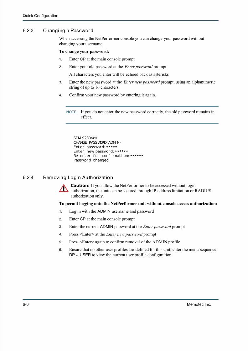
7/23/2019 04 Quick Configuration
http://slidepdf.com/reader/full/04-quick-configuration 90/102
Quick Configuration
6-6 Memotec Inc.
6.2.3 Changing a Password
When accessing the NetPerformer console you can change your password withoutchanging your username.
To change your password:
1. Enter CP at the main console prompt
2. Enter your old password at the Enter password prompt
All characters you enter will be echoed back as asterisks
3. Enter the new password at the Enter new password prompt, using an alphanumericstring of up to 16 characters
4. Confirm your new password by entering it again.
NOTE: If you do not enter the new password correctly, the old password remains ineffect.
SDM- 9230> CPCHANGE PASSWORD( ADMI N)Ent er passwor d: *****Ent er new passwor d: ******Re- ent er f or conf i r mat i on: ******Passwor d changed
6.2.4 Removing Login Author izat ion
Caution: If you allow the NetPerformer to be accessed without loginauthorization, the unit can be secured through IP address limitation or RADIUSauthorization only.
To permit logging onto the NetPerformer unit without console access authorization:
1. Log in with the ADMIN username and password
2. Enter CP at the main console prompt
3. Enter the current ADMIN password at the Enter password prompt
4. Press <Enter> at the Enter new password prompt
5. Press <Enter> again to confirm removal of the ADMIN profile
6. Ensure that no other user profiles are defined for this unit; enter the menu sequenceDP USER to view the current user profile configuration.

7/23/2019 04 Quick Configuration
http://slidepdf.com/reader/full/04-quick-configuration 91/102
Controlling Access to the NetPerformer
Memotec Inc. 6-7
6.3 Restricting FTP AccessAccess to the NetPerformer unit via FTP can be restricted to up to 5 IP addresses, ordisabled altogether. This is accomplished by changing the IP/FTP configuration.
To define the IP addresses that can access the unit via FTP:
1. Enter the menu sequence: SE IP FTP
2. Enter DISABLE at the Mode parameter prompt to block FTP access from any IPaddress. No further parameters are presented in this case.
Otherwise, leave the Mode parameter at its default value, ENABLE , to permit FTPaccess to the NetPerformer unit
3. Enter the authorized IP addresses one at a time, as in the following example.
SDM- 9230> SESETUPI t em ( BRI DGE/ CALLER I D/ CLASS/ CUSTOM/ FI LTER/ GLOBAL/ HUNT/ I P/ I PX/ MAP/PHONE/PORT/ PU/ PPPOE/ PPPUSER/ PVC/ REDUNDANCY/ SCHEDULE/ SLOT/ USER/ VLAN,def : BRI DGE) ? IPI t em ( GLOBAL/ STATI C/ BOOTP/ OSPF/ TI MEP/ SNMP/ NAT/ TELNET/ FTP/ DNS/
RADI US,def : TELNET) ? FTPFTP> Mode ( def : ENABLE) ?FTP> FTP: I P addr ess 1 ( def : 000. 000. 000. 000) ? 102.98.31.1FTP> FTP: I P addr ess 2 ( def : 000. 000. 000. 000) ? 102.98.31.5FTP> FTP: I P addr ess 3 ( def : 000. 000. 000. 000) ? 102.98.31.27FTP> FTP: I P addr ess 4 ( def : 000. 000. 000. 000) ?FTP> FTP: I P addr ess 5 ( def : 000. 000. 000. 000) ?
Figure 6-2: SETUP/IP/FTP Path on the CLI Tree

7/23/2019 04 Quick Configuration
http://slidepdf.com/reader/full/04-quick-configuration 92/102
Quick Configuration
6-8 Memotec Inc.
If FTP access is enabled, and you leave all 5 authorized IP addresses at their default value,000.000.000.000 , the NetPerformer unit can be accessed from any IP device thatsupports FTP.
Caution: If you allow the NetPerformer to be accessed via FTP without IPaddress limitation, the unit can be secured through login authorization or RADIUSauthorization only.

7/23/2019 04 Quick Configuration
http://slidepdf.com/reader/full/04-quick-configuration 93/102
Controlling Access to the NetPerformer
Memotec Inc. 6-9
6.4 Restricting Telnet AccessAccess to the NetPerformer console via a Telnet connection can be restricted to up to 5 IPaddresses, or disabled altogether. This is accomplished by changing the IP/TELNET configuration.
To define the IP addresses that can access the console via Telnet:
1. Enter the menu sequence: SE IP TELNET
2.Enter
DISABLE at the Mode parameter prompt to block Telnet access from any IPaddress. No further parameters are presented in this case,
Otherwise, leave the Mode parameter at its default value, ENABLE , to permit Telnetaccess to the NetPerformer console
3. Enter the authorized IP addresses one at a time, as in the following example.
SDM- 9230> SESETUPI t em ( BRI DGE/ CALLER I D/ CLASS/ CUSTOM/ FI LTER/ GLOBAL/ HUNT/ I P/ I PX/ MAP/PHONE/PORT/ PU/ PPPOE/ PPPUSER/ PVC/ REDUNDANCY/ SCHEDULE/ SLOT/ USER/ VLAN,def : BRI DGE) ? IPI t em ( GLOBAL/ STATI C/ BOOTP/ OSPF/ TI MEP/ SNMP/ NAT/ TELNET/ FTP/ DNS/RADI US,def : NAT) ? TELNET
TELNET> Mode ( def : ENABLE) ? TELNET> TELNET: I P addr ess 1 ( def : 000. 000. 000. 000) ? 102.98.31.1 TELNET> TELNET: I P addr ess 2 ( def : 000. 000. 000. 000) ? 102.98.31.5 TELNET> TELNET: I P addr ess 3 ( def : 000. 000. 000. 000) ? 102.98.31.27 TELNET> TELNET: I P addr ess 4 ( def : 000. 000. 000. 000) ? TELNET> TELNET: I P addr ess 5 ( def : 000. 000. 000. 000) ?
Figure 6-3: SETUP/IP/TELNET Path on the CLI Tree

7/23/2019 04 Quick Configuration
http://slidepdf.com/reader/full/04-quick-configuration 94/102
Quick Configuration
6-10 Memotec Inc.
If Telnet access is enabled, and you leave all 5 authorized IP addresses at their defaultvalue, 000.000.000.000 , the NetPerformer unit can be accessed from any IP devicethat supports Telnet.
Caution: If you allow the NetPerformer to be accessed via Telnet without IPaddress limitation, the unit can be secured through login authorization or RADIUSauthorization only.

7/23/2019 04 Quick Configuration
http://slidepdf.com/reader/full/04-quick-configuration 95/102
Controlling Access to the NetPerformer
Memotec Inc. 6-11
6.5 Authentication Using RADIUSThe NetPerformer supports Remote Authentication Dial-In User Service (RADIUS) forauthentication of console and Telnet access to the network. The NetPerformerimplementation follows the RFC-2865 specification. In this implementation:
• The RADIUS server software and a database of user profiles are installed on adedicated workstation in the network
• Access privileges are determined individually for each username in the database,as either FULL or MONITOR access
• Login requests received at a participating NetPerformer unit are forwarded to theRADIUS server for authentication using the RADIUS protocol and a SharedSecret
• The RADIUS server is able to authenticate login requests from all participating NetPerformer units (clients) in the network.
Advantages of using a RADIUS server are:
• The authentication process is centralized in a distributed client/server system
• User authentication is simpler and more secure
• The addition and removal of user profiles does not require configuration changeson several units in the network.
6.5.1 At tr ibutes Supported
The following standard RADIUS attributes are supported in the NetPerformerimplementation, as defined in the RFC-2865 specification:
6.5.2 Login ProcedureWhen a remote user dials into a NetPerformer unit the usual login procedure is initiated:
• The NetPerformer requests a LOGIN (username) and PASSWORD for authenti-cation purposes.
At tr ibute No. Standard Name NetPerfo rmer Equivalent
1 User-Name LOGIN
2 User-Password PASSWORD
4 NAS-IP-Address NetPerformer IP address
6 Service-Type Access privilege (FULL or MONITOR)
18 Reply-Message Access-Accept or Access-Reject
Table 1Standard RADIUS Attributes Supported in the NetPerformer Implementation

7/23/2019 04 Quick Configuration
http://slidepdf.com/reader/full/04-quick-configuration 96/102
Quick Configuration
6-12 Memotec Inc.
• Once the user enters the LOGIN and PASSWORD , the NetPerformer searches theset of User Profiles that have been configured locally on the unit. Refer to“Defining the User Profiles” on page 6-3 .
• If a match is found in the local User Profiles, the user is logged on with the Access privilege (FULL or MONITOR ) that is defined in the User Profile.
If no match is found in the local User Profiles, the NetPerformer turns to the RADIUSServer for authentication:
• The NetPerformer builds a RADIUS Access-Reques t packet from the login and password encrypted with the Shared Secret , and forwards the login request tothe RADIUS Server for authentication.
• The RADIUS Server de-encrypts the login request using the Shared Secret ,and searches its database for the login/password combination.
• The RADIUS Server returns its verdict to the NetPerformer in the form of an Access-Accept or Access-Reject message. If the user is authorized to accessthe unit, the RADIUS Server also indicates the type of access privilege ( FULL or
MONITOR ) that is allowed for this user.• The NetPerformer responds to an Access-Accept message by logging the user
on with the indicated access privileges. It responds to an Access-Reject message by displaying the following at the console:
Radi us Aut hent i cat i on r ef used. . . I nval i d Passwor d.

7/23/2019 04 Quick Configuration
http://slidepdf.com/reader/full/04-quick-configuration 97/102
Controlling Access to the NetPerformer
Memotec Inc. 6-13
6.5.3 Configuring the NetPerformer for RADIUS Authentication
The criteria for RADIUS authentication are defined at the console using the IP/RADIUS submenu of the Setup ( SE ) command. The NetPerformer can be defined as a RADIUSclient only.
To configure the NetPerformer as a client for RADIUS authentication:
• Enter the menu sequence: SE IP RADIUS
• Specify the Radius Server IP Address• Define the Transmission timeout in seconds (default 1 second)
• Define the number of Transmission Retries that the unit can make to theRADIUS Server for a single login request (default 1)
• Enter the Radius Shared Secret (maximum 16 ASCII characters)
Caution: The Shared Secret must also be configured on the RADIUSServer.
• To enable authentication of console users, enter YES after the Console Authenti-cation parameter prompt (default NO)
• To enable authentication of Telnet users, enter YES after the Telnet Authentica-tion parameter prompt (default NO).
Here is an example of the required configuration:
BOSTON> SESETUPI t em ( BRI DGE/ CALLER I D/ CLASS/ CUSTOM/ FI LTER/ GLOBAL/ HUNT/ I P/ I PX/ MAP/PHONE/
Figure 6-4: SETUP/IP/RADIUS Path on the CLI Tree

7/23/2019 04 Quick Configuration
http://slidepdf.com/reader/full/04-quick-configuration 98/102
Quick Configuration
6-14 Memotec Inc.
PORT/ PU/ PPPOE/ PPPUSER/ PVC/ REDUNDANCY/ SCHEDULE/ SLOT/ USER/ VLAN,def : BRI DGE) ? IPI t em ( GLOBAL/ STATI C/ BOOTP/ OSPF/ TI MEP/ SNMP/ NAT/ TELNET/ FTP/ DNS/RADI US, def : GLOBAL) ? RADIUSRADI US> Radi us Server I P Address ( def : ) ? 194.012.034.107RADI US> Transmi ssi on t i meout ( s) ( 1- 5) , def : 1) ? 4RADI US> Transmi ssi on Ret r i es ( 1- 5, def : 1) ? 3
RADI US> Radi us Shar ed Secr et ( def : ) ? SECURE NP ACCESSRADI US> Consol e Aut hent i cat i on ( def : NO) ? YESRADI US> Tel net Aut henti cat i on ( def : NO) ? YES
6.5.4 Example of Console Access
Here is an example of an authenticated user login request from the NetPerformer console:
LOGI N: JHUNTER PASSWORD: ********Radi us Aut hent i cat i on conf i r med [Monitor Access]
Net Per f or mer SDM- 9360 vX. X. X Memot ec I nc. ( c) 2003Si gnal i ng Engi ne X. X. XDSP code vers i on: X. X. XConsol e connect ed on por t CSL
NOTE: The notation [Monitor Access] in this example will appear as [Full Access] for users with FULL access privileges to NetPerformer functions.
6.5.5 Example of Telnet Access
If a user is allowed access to the NetPerformer under Telnet Authentication , the following
information is logged in the alarm file:CHI CAGO> DA DI SPLAY ALARMSNet Per f or mer SDM- 9380 vX. X. X Memot ec I nc. ( c) 2003Si gnal i ng Engi ne X. X. XConsol e connect ed t hr ough TELNET
Ti me> FRI 2003/ 07/ 25 11: 14: 04Al ar m> USER J HUNTER FRI 2003/ 07/ 2511: 14: 02Al ar m> LOGGED I N VI A TELNET [radius/FA] FRI 2003/ 07/ 2511: 14: 02
NOTE: The notation [radius/FA] in this example indicates a RADIUS authenticationconfirmation with FULL access privileges. Authentication confirmation withMONITOR access is represented by [radius/MA] .

7/23/2019 04 Quick Configuration
http://slidepdf.com/reader/full/04-quick-configuration 99/102
Quick Configuration 1
Index
AAccess
user profiles 3-3Alarms
preventing 6-6user access 5-5
Auto Save Configuration Delay 15-15
BBackplane links, enabling RIP version 19-19
CChange Password command 6-6Channel statistics 4-4Class
for voice traffic 13-13high priority voice 13-13
CLI tree 2-2top levels 2-2
Command line interface 2-2Compression dictionary statistics 6-6Conditioned link activation 12-12Console
access 3-3MONITOR access 3-3
Contact Name 5-5Country Code 11-11CP command 6-6
DDedicated WAN link 2-2 , 15-15 , 32-32Default Gateway 8-8Default IP Address 6-6Default IP Mask 7-7Delay
transit 6-6Delay Generated by a Comma 15-15Dial Timer 12-12Dictionaries, status of 6-6Display Errors, channel status 4-4Display Errors, compression dictionary status 6-6Display States command 9-9DLCI address
of local unit 10-10
EEnable Domain Dialing 16-16Enable Hunt Forwarding 17-17Enable User Access Logging 17-17Enable Voice/Fax Log 12-12Enable VTR 16-16Exclusive Access to Console 17-17Extension Number 11-11
FFans, monitoring 9-9
Frame Relay Status Change Trap 9-9FTP access 7-7 , 9-9
GGateway, default 8-8Global CIR for FR over IP 14-14Global parameters 2-2
for rackmount chassis 18-18
HHE command, with MONITOR access 4-4High Priority Voice Class 13-13
IIP address
default 6-6of SNMP trap 8-8
IP RIPenabling 19-19
IPX RIP for Backplane Links 20-20IPX SAP for Backplane Links 20-20ISDN G4 Fax PCM Switching Enable 15-15
JJitter Buffer 12-12
LLink
preventing LINK DOWN alarms 6-6timeout 6-6
Link activationby user port activity 12-12
Link Timeout Delay 6-6

7/23/2019 04 Quick Configuration
http://slidepdf.com/reader/full/04-quick-configuration 100/102
2 Memotec Inc.
Local Unit DLCI Address 10-10Log
voice/fax, enabling 12-12Logical connections, status of 4-4Loopback 5-5
control of 5-5
MMax number of voice channels over IP 14-14Modem signals
and conditioned link activation 12-12
OOSPF for Backplane Links 20-20
PParameter list
Auto Save Configuration Delay 15-15Contact Name 5-5Country Code 11-11Default Gateway 8-8Default IP Address 6-6Default IP Mask 7-7Delay Generated by a Comma 15-15Dial Timer 12-12Enable Domain Dialing 16-16Enable Hunt Forwarding 17-17Enable User Access Logging 17-17Enable Voice/Fax Log 12-12Enable VTR 16-16Exclusive Access to Console 17-17
Extension Number 11-11Frame Relay Status Change Trap 9-9Global CIR for FR over IP 14-14High Priority Voice Class 13-13IPX RIP for Backplane Links 20-20IPX SAP for Backplane Links 20-20ISDN G4 Fax PCM Switching Enable 15-15Jitter Buffer 12-12Link Timeout Delay 6-6Local Unit DLCI Address 10-10Loopback 5-5Max. number of voice channels over IP 14-14OSPF for Backplane Links 20-20Rack ID 18-18RIP Version for Backplane Links 19-19SNMP Trap
IP Address 8-8Timer in ms for FR over IP 14-14Transit Delay 6-6Unit Location 5-5Unit Name 4-4Unit Routing Version 4-4
Voice Class 13-13Watch Power Supplies and Fans 9-9
ParametersFTP 7-7 , 9-9Global 2-2
Global, for rackmount chassis 18-18PVCR port 2-2 , 15-15 , 32-32User 3-3
Passwordchanging 6-6
PortWAN 2-2 , 15-15 , 32-32
Power supply, monitoring 9-9PVCR
port, WAIT-USER mode 12-12
R Rack ID 18-18Rackmount chassis
identification 18-18RADIUS support 11-11
configuration 13-13RIP Version for Backplane Links 19-19Routing
IP 19-19
SSNMP Trap IP Address 8-8SNMP trap, IP address 8-8Subnet mask
default 7-7System status, displaying 4-4
TTimeout
link 6-6Timer in ms for FR over IP 14-14Transit Delay 6-6Trap, IP address for 8-8
UUnit Location 5-5Unit Name 4-4Unit Routing Version 4-4
User parameters 3-3User profile 3-3
VVersion
for IP RIP 19-19Voice Class 13-13

7/23/2019 04 Quick Configuration
http://slidepdf.com/reader/full/04-quick-configuration 101/102
Quick Configuration 3
WWAIT-USER mode 12-12WAN link 2-2 , 15-15 , 32-32Watch Power Supplies and Fans 9-9

7/23/2019 04 Quick Configuration
http://slidepdf.com/reader/full/04-quick-configuration 102/102