ˆ ˛ ˘ ! ˇ˙˜ ˝˜ ˛ ˙ ˘ - Rockwell...
72
User Manual Remote I/O Adapter Modle (Cat. No. 1794"ASB Series E) Allen"Bradle!
Transcript of ˆ ˛ ˘ ! ˇ˙˜ ˝˜ ˛ ˙ ˘ - Rockwell...

"
"!
Because of the variety of uses for the products described in thispublication, those responsible for the application and use of theseproducts must satisfy themselves that all necessary steps have beentaken to assure that each application and use meets all performance andsafety requirements, including any applicable laws, regulations, codesand standards. In no event will Rockwell Automation be responsible orliable for indirect or consequential damage resulting from the use orapplication of these products.
Any illustrations, charts, sample programs, and layout examples shownin this publication are intended solely for purposes of example. Sincethere are many variables and requirements associated with any particularinstallation, Rockwell Automation does not assume responsibility orliability (to include intellectual property liability) for actual use basedupon the examples shown in this publication.
Allen–Bradley publication SGI–1.1, Safety Guidelines for Application,Installation, and Maintenance of Solid–State Control (available fromyour local Rockwell Automation office), describes some importantdifferences between solid–state equipment and electromechanicaldevices that should be taken into consideration when applying productssuch as those described in this publication.
Reproduction of the contents of this copyrighted publication, in whole orpart, without written permission of Rockwell Automation, is prohibited.
Throughout this publication, notes may be used to make you aware ofsafety considerations. The following annotations and their accompanyingstatements help you to identify a potential hazard. avoid a potentialhazard, and recognize the consequences of a potential hazard.
WARNING
!Identifies information about practices orcircumstances that can cause an explosion in ahazardous environment, which may lead to personalinjury or death, property damage, or economic loss.
ATTENTION
!Identifies information about practices orcircumstances that may lead to personal injury ordeath, property damage, or economic loss.
IMPORTANTIdentifies information that is critical forsuccessful application and understanding of theproduct.

ATTENTION
!
Environment and Enclosure
This equipment is intended for use in a PollutionDegree 2 industrial environment, in overvoltageCategory II applications (as defined in IEC publication60664–1), at altitudes up to 2000 meters withoutderating.
This equipment is considered Group 1, Class Aindustrial equipment according to IEC/CISPRPublication 11. Without appropriate precautions, theremay be potential difficulties ensuring electromagneticcompatibility in other environments due to conductedas well as radiated disturbance.
This equipment is supplied as “open type” equipment.It must be mounted within an enclosure that is suitablydesigned for those specific environmental conditionsthat will be present, and appropriately designed toprevent personal injury resulting from accessibility tolive parts. The interior of the enclosure must beaccessible only by the use of a tool. Subsequentsections of this publication may contain additionalinformation regarding specific enclosure type ratingsthat are required to comply with certain product safetycertifications.
See NEMA Standards publication 250 and IECpublication 60529, as applicable, for explanations ofthe degrees of protection provided by different types ofenclosures. Also, see the appropriate sections in thispublication, as well as the Allen–Bradley publication1770–4.1, (“Industrial Automation Wiring andGrounding Guidelines”), for additional installationrequirements pertaining to this equipment.
ATTENTION
!FLEX I/O is grounded through the DIN rail to chassisground. Use zinc plated, yellow chromated steel DINrail to assure proper grounding. Using other DIN railmaterial (e.g. aluminum, plastic, etc.) which cancorrode, oxidize or are poor conductors can result inimproper or intermittent platform grounding.

ATTENTION
!Preventing Electrostatic DamageThis equipment is sensitive to electrostatic discharge,which can cause internal damage and affect normaloperation. Follow these guidelines when you handlethis equipment.
• Touch a grounded object to discharge potentialstatic.
• Wear an approved grounding wriststrap.• Do not touch connectors or pins on component
boards.• Do not touch components inside the equipment.• If available, use a static–safe workstation.• When not in use, keep modules in appropriate
static–safe packing.

The information below summarizes the changes to the Remote I/OAdapter User Manual, publication 1794-UM009D–EN–P, since thelast release.
The series E adapter is capable of recognizing the safe state data forthe FLEX Integra analog modules, and allows use of 32 point FLEXI/O modules. You must use a series D or later adapter when usingFLEX Integra analog modules in your system.
The following new information is included in this version of thepublication:
Switch positions on S! and S2 were incorrectly identified in theprevious version of this publication. Corrections have been made onpage 2–11 of Chapter 2.
New modules available since the last version of this publication havebeen added.
The areas in this manual which are different from previous editionsare marked with change bars (as shown to the right of this paragraph)to indicate the addition of new or revised information.

soc–ii Summary of Changes

1!)(" 0(,+ 5 -.()
Read this preface to familiarize yourself with this manual and tolearn how to use it properly and efficiently.
IMPORTAN T,1 *1/0 1/$ /$.($/ ,. ) 0$. # -0$. 0,
",**1+(" 0$ 3(0' +0$&. + ),& *,#1)$/ ,1
*1/0 1/$ /$.($/ ,. ) 0$. # -0$. 0, ",**1+(" 0$
3(0' -,(+0 *,#1)$/
We assume that you have previously used an Allen–Bradleyprogrammable controller, that you are familiar with its features, andthat you are familiar with the terminology we use. If not, read theuser manual for your processor before reading this manual.
In this manual, we refer to:
• the individual adapter module as the “adapter.”
• the programmable controller as the “controller” or the“processor.”
• input and output modules as the “module.”
The contents of this manual are as follows:
2$.2($3 ,% +# 0'$ $*,0$
# -0$. ,#1)$
$/".(!$/ %$ 01.$/ " - !()(0($/ +# ' .#3 .$
",*-,+$+0/
+/0 ))(+& ,1. $*,0$ # -0$. .,"$#1.$/ +# &1(#$)(+$/ %,. (+/0 ))(+& 0'$ *,#1)$
,**1+(" 0(+& 3(0' ,#1)$/ .#3 .$ ##.$//(+& +# ",+%(&1. 0(,+ ,-0(,+/
.,1!)$/',,0(+& .,1!)$/',,0(+& (#/
!
-$"(%(" 0(,+/ ,#1)$ /-$"(%(" 0(,+/
(%%$.$+"$/ $03$$+ $.($/
+# $*,0$ # -0$./
%$04 --.,2 )/
"

Using This ManualP–2
1!)'" 0',+ 4 -.')
We use these conventions in this manual:
! " $ $ !
0& 0 0&$.$ '/ *,.$ '+%,.* 0',+ !,10 0,-'"
'+ +,0&$. "& -0$. '+ 0&'/ * +1 )
0& 0 0&$.$ '/ *,.$ '+%,.* 0',+ !,10 0&$
0,-'" '+ +,0&$. * +1 )
More
For additional information on FLEX I/O systems and modules, referto the following documents:
!"!
!
"! ! !!
!"!
"
.,#1"0 0 4
4 #" ,+0.,)$0 # -0$. 4
4 #" $#1+# +0 $#' ,+0.,)$0 # -0$. 4
4 #" ,+0.,)$0 # -0$. 4
4 #" $#1+# +0 $#' ,+0.,)$0 # -0$. 4
4 #" $2'"$$0 # -0$. 4 4
4 #" $*,0$ # -0$. 4 4
4 #" 4),0 $*,0$ # -0$. 4 4
4 #" .,%'!1/ # -0$. 4 4
4 #" '+( +-10 ,#1)$ 4
4 #" ,1."$ 10-10 ,#1)$ 4
4 #" '+( +-10 ,#1)$ 4
4 #" ,1."$ 10-10 ,#1)$ 4
4 #" ,1."$ 10-10 ,#1)$ 4
4 #" ,1."$ 10-10 ,#1)$ 4
4 #" )$"0.,+'" ))3 1/$# 10-10 ,#1)$ 4
4 #" ,1."$ +-10 ,#1)$ 4
4 #" '+( 10-10 ,#1)$ 4
4 #" )$"0.,+'" ))3 1/$# 10-10 ,#1)$ 4
4 #" )$"0.,+'" ))3 1/$# 10-10 ,#1)$ 4
4 #" $+/,. +-10 ,#1)$ 4
4 #" +-10 10-10 ,#1)$ 4
4 #" +-10 10-10 ,#1)$ 4
!" %!
#!
! !

Using This Manual P–3
5%,+&$4+/. 8 02+,
8" ! '& (,$7 54054 /'5,( 8
8 ! '& (,(&4$%,( .$,/) .054 /'5,( 8
8 ! '& (,(&4$%,( .$,/) 54054 /'5,( 8 8
8# ! '& .054 54054 .$,/) /'5,( 8
8 ! '& 54054 3/,$4(' .$,/) /'5,( 8
8 ! '& .054 3/,$4(' .$,/) /'5,( 8 8
8# ! '& .054 54054 3/,$4(' .$,/) /'5,( 8
8 ! '& .054 .$,/) /'5,( 8 8
8 ! '& *(2-/&/50,( .054 /'5,( 8 8
8 ! '& *(2-/&/50,( .054 /'5,( 8 8
8 ! '& 2(15(.&7 .054 /'5,( 8 8
8 ! '& *$..(, 2(15(.&7 .054 /'5,( 8 8
8 ! '& *$..(, 5,3( /5.4(2 /'5,( 8 8
8 ! '& +)* 0((' /5.4(2 /'5,( 8 8
8 ! '& ! '& .054 /'5,( 8
8 ! '& ! '& 54054 /'5,( 8
8 ! $& .054 /'5,( 8
8 ! $& 54054 /'5,( 8
8 ! $& 3/,$4(' .054 /'5,( 8
8 ! $& 3/,$4(' 54054 /'5,( 8
8 ! $& .054 /'5,( 8
8 ! $& 54054 /'5,( 8
8 !
$&'&
.054 /'5,(8
8 !
$&'&
54054 /'5,(8
8
8
86+2( (2-+.$, $3(
86+2( (2-+.$, $3(8
8 (2-+.$, $3( .+4 8
8 53(' (2-+.$, $3( .+4 8
8 (-0(2$452( (2-+.$, $3( .+4 8
8 02+.) ,$-0 (2-+.$, $3( .+4 8
8 02+.) ,$-0 (-0(2$452( $3( .+4 8
8 (2-+.$, $3( .+4 8
8 02+.) ,$-0 (2-+.$, $3( .+4 8
8 $)( ,$-0 (2-+.$, $3( .+4 8
8 02+.) ,$-0 (2-+.$, $3( .+4 8

Using This ManualP–4
7&.-'%6-10 ;" 24-.
; ; 96)0()4 %&.)5 ;
; 1706-0+ -6 ;
; # (' 18)4 722.: ;
; # (' 18)4 722.: ;
; )) 016) " -+-6%. 0276 1(7.) ;
; )) 016) 9 174') -+-6%. 76276 1(7.) ;
; )) 016) ).)'6%&.) 0276 1(7.) ;
; )) 016) ).)'6%&.) -.6)4 0%.1+ 0276 1(7.) ;
; )) 016) ).)'6%&.) 0%.1+ 76276 1(7.) ;
;! )) 016) !,)4/1'172.)! 0276 1(7.) ;
; )) 016) 4)37)0': 0276 1(7.) ;
;!
;!
;8-4) '4)8 .%/2 !)4/-0%. %5)
;8-4) 24-0+ .%/2 !)4/-0%. %5)
;
;
; )) 016) 75 51.%614 ;
; )) 016) $ 9 75 100)'614 ;
16) 064-05-'%..: %*) #1.6%+)
ATTENTION
!FLEX I/O is grounded through the DIN rail to chassisground. Use zinc plated, yellow chromated steel DINrail to assure proper grounding. Using other DIN railmaterials (e.g. aluminum, plastic, etc.) which cancorrode, oxidize or are poor conductors can result inimproper or intermittent platform grounding.

Using This Manual P–5
!ATTENTION
This equipment is sensitive to electrostaticdischarge, which can cause internal damage andaffect normal operation. Follow these guidelineswhen you handle this equipment:
• Touch a grounded object to discharge potentialstatic.
• Wear an approved grounding wriststrap.
• Do not touch connectors or pins on componentboards.
• Do not touch circuit components inside theequipment.
• If available, use a static–safe workstation.
• When not in use, keep modules in appropriatestatic–safe packaging.
!WARNING Remove field-side power before removing or
inserting this module. This module is designed soyou can remove and insert it under backplanepower. When you remove or insert a module withfield-side power applied, an electrical arc mayoccur. An electrical arc can cause personal injury orproperty damage by:
• sending an erroneous signal to your system’sfield devices causing unintended machine motion
• causing an explosion in a hazardous environmentRepeated electrical arcing causes excessive wear tocontacts on both the module and its matingconnector. Worn contacts may create electricalresistance.

Using This ManualP–6
This preface gave you information on how to use this manualefficiently. The next chapter introduces you to the remote I/Oadapter module.

8%/,&$7,21 =! 35,/
+$37(5 %-(&7,9(6
+( # <67(0
2: # 2'8/(6 20081,&$7( :,7+ 52*5$00$%/( 21752//(56
$5':$5( 20321(176
,$*1267,& 1',&$7256
(6(7 86+%87721
(027( ",5,1*
2:(5 ",5,1*
''5(66 :,7&+ 66(0%/,(6
+$37(5 800$5<
+$37(5 %-(&7,9(6
2:(5 (48,5(0(176
2817,1* 7+( (027( '$37(5
2817,1* 21 $ $,/ %()25( ,167$//,1* 7+( 7(50,1$/ %$6( 81,76
2817,1* 25 (3/$&,1* 7+( '$37(5 21 $1 ;,67,1* <67(0
2817,1* 21 $ "$// 25 $1(/
",5,1*
(77,1* 7+( :,7&+(6
7$57,1* 5283
$&. 80%(5
2/' 13876
$&. $8/7 (/(&7 :,7&+
''5(66,1* 2'( (/(&7,21 :,7&+(6
20081,&$7,21 $7(
52&(6625 (67$57 2&.287
2/' $67 7$7(
(77,1* 7+( 2'( (/(&7,21 :,7&+(6
(77,1* 7+( ''5(66 :,7&+(6
(77,1* 7+( ''5(66 :,7&+(6 )25 203/(0(17$5<
5,0$5< $&.
203/(0(17$5< $&.
+$37(5 800$5<
+$37(5 %-(&7,9(6
# 2'8/( $7$
''5(66,1*
1$/2* /2&. 5$16)(5 2'8/(6
""#
$!
!
!
!
! #
!
Table of Contents

Table of Contents
3!+(" 2(.- 8 /0(+
2 -# 0# ##0$11(-&
2 -# 0# ##0$11(-&
.,/ "2 ##0$11(-&
.,/ "2 .#$
.,/+$,$-2 06 ##0$11(-& .#$
.,/+$,$-2 06 .#$ 8/.(-2
.,/+$,$-2 06 .#$ 8/.(-2
.,/+$,$-2 06 ##0$11(-&
//(-& 2 (-2. 2'$ , &$ !+$1
$2$0,(-(-& "* (7$
/$0 2(-& .#$1
' /2$0 3,, 06
' /2$0 !)$"2(4$1
3+2 .-#(2(.-1
0.3!+$1'..2(-& 5(2' 2'$ -#(" 2.0 (&'21
' /2$0 3,, 06
#
/$"(%(" 2(.-1
#
(%%$0$-"$1 $25$$- $,.2$ # /2$0 $0($1 -#
#
%$26 //0.4 +1
"
$ !

In this chapter, we tell you about:
• what the FLEX I/O system is and what it contains
• how FLEX I/O modules communicate with programmablecontrollers
• the features of your adapter module
FLEX I/O is a small, modular I/O system for distributedapplications that performs all of the functions of rack-based I/O. TheFLEX I/O system contains the following components shown below:
• adapter/power supply – powers the internal logic for as many aseight I/O modules
• terminal base – contains a terminal strip to terminate wiring fortwo- or three-wire devices
• I/O module – contains the bus interface and circuitry needed toperform specific functions related to your application
!

1–2 Overview of FLEX I/O and your Remote I/O Adapter Module
8'/.(&7.21 =" 35./
Data transfer to and from the remote I/O adapter/power supply anddiscrete I/O modules occurs every flexbus scan. This provides thecontroller with updated data.
The remote I/O adapter/power supply transfers data to the analog I/Omodule (block transfer write) and from the analog I/O module (blocktransfer read) using BTW and BTR instructions in your ladderdiagram program. These instructions let the adapter obtain inputvalues and status from the I/O module, and let you send outputvalues to establish the module’s mode of operation. Thecommunication process is described in the following illustration.
!
!# "!
"!
#
$ "%
!
=
"! "! "! "! "! "! "! "! # # # # # # # #
"!
!-* &)&37*5 75&16+*56 <285 (21+.,85&7.21 )&7&
72 7-* 02)8/* 86.1, & !$
/*;'86
;7*51&/ )*9.(*6 75&160.7
&1&/2, 6.,1&/6 72 7-* 02)8/*
!-* 02)8/* (219*576 &1&/2, 6.,1&/6
.172 '.1&5< +250&7 &1) 6725*6 7-*6*
9&/8*6 817./ 7-* &)&37*5 5*48*676 7-*.5
75&16+*5
%285 /&))*5 352,5&0 .16758(76 7-*
&)&37*5 72 3*5+250 & ! 2+ 7-* 9&/8*6
&1) 6725*6 7-*0 .1 & )&7& 7&'/*
!-* &)&37*5 &1) 02)8/* )*7*50.1*
7-&7 7-* 75&16+*5 :&6 0&)* :.7-287 *5525
&1) .1387 9&/8*6 &5* :.7-.1 63*(.+.*)
5&1,*
%285 /&))*5 352,5&0 (&1 86* &1)25 029* 7-* )&7& .+ 9&/.)
'*+25* .7 .6 :5.77*1 29*5 '< 7-* 75&16+*5 2+ 1*: )&7& .1 &
68'6*48*17 75&16+*5
%285 /&))*5 352,5&0 3*5+2506 !$6 72 7-* 02)8/* :-*1 <28 32:*5
.7 83 &1) &1< 7.0* <28 :.6- 72 5*(21+.,85* 7-* 02)8/*
$

1–3Overview of FLEX I/O and your Remote I/O Adapter Module
3$+*%#2*.- 6 /0*+
The adapter module consists of the following major components:
• diagnostic indicators
• reset pushbutton
• remote I/O wiring connections
• 24V dc power wiring connections
• address/group switch assemblies
*#(-.12*% -&*%#2.01
'1'2 31)$322.-
&% !*0*-( .--'%2*.-1
&% .,,.- !*0*-( .--'%2*.-1
',.2' !*0*-( .--'%2*.-1 %.--'%2.0 /#02 -.
&&0'110.3/ 4*2%)'1
++'-60#&+'5
! "
!
Diagnostic indicators are located on the front panel of the adaptermodule. They show both normal operation and error conditions inyour remote I/O system. The indicators are:
• Power ON (green)• Adapter ACTIVE (green)• Adapter FAULT (red)• LOCAL FAULT (red)
A complete description of the diagnostic indicators and how to usethem for troubleshooting is explained in chapter 4.

1–4 Overview of FLEX I/O and your Remote I/O Adapter Module
Use the reset pushbutton to reset the adapter module and resumecommunication when a communication error occurs. (The adapter’s processor restart lockout switch (PRL) must be in the “locked out”position.) If the adapter is not locked out by the PRL switch, it will be automatically reset via special commands sent over thecommunication link.
Do not cycle power to the adapter to clear a fault. Allqueued block transfer instructions will be lost.
The remote I/O wiring termination is made to a plug-in connector onthe front of the adapter module. Refer to Chapter 2 for informationon wiring the connector.
Connections are provided for connecting the required 24V dc powerto the front of the module. The power wiring can be daisy-chained tothe terminal base unit located next to the adapter to supply power tothe module installed in that base unit. Wiring information is shown inChapter 2.
Multi-position switches are provided for:
• starting I/O group
• I/O rack number
• hold inputs
• mode switches for mode 0, mode 1, mode 2, mode 3 and mode 4
• rack fault
• communication rate
• processor restart lockout (PRL)
• hold last state (outputs)
These switches are accessed by lifting the hinged cover on the frontof the module. Refer to Chapter 2 for switch settings.
In this chapter you learned about the FLEX I/O system and featuresof the remote I/O adapter module.
87
65
43
21
87
65
43
21

This chapter describes the procedures for installing your remote I/Oadapter module. These include:
• power requirements
• mounting the remote I/O adapter
• setting the module switches
ATTENTION
!Environment and Enclosure
This equipment is intended for use in a PollutionDegree 2 industrial environment, in overvoltageCategory II applications (as defined in IECpublication 60664–1), at altitudes up to 2000meters without derating.
This equipment is considered Group 1, Class Aindustrial equipment according to IEC/CISPRPublication 11. Without appropriate precautions,there may be potential difficulties ensuringelectromagnetic compatibility in otherenvironments due to conducted as well as radiateddisturbance.
This equipment is supplied as “open type”equipment. It must be mounted within anenclosure that is suitably designed for thosespecific environmental conditions that will bepresent, and appropriately designed to preventpersonal injury resulting from accessibility to liveparts. The interior of the enclosure must beaccessible only by the use of a tool. Subsequentsections of this publication may contain additionalinformation regarding specific enclosure typeratings that are required to comply with certainproduct safety certifications.
See NEMA Standards publication 250 and IECpublication 60529, as applicable, for explanationsof the degrees of protection provided by differenttypes of enclosures. Also, see the appropriatesections in this publication, as well as theAllen–Bradley publication 1770–4.1, (“IndustrialAutomation Wiring and Grounding Guidelines”),for additional installation requirements pertainingto this equipment.

2–2 Installing Your Remote I/O Adapter Module
ATTENTION
!
This equipment is sensitive to electrostaticdischarge, which can cause internal damage andaffect normal operation. Follow these guidelineswhen you handle this equipment:
• Touch a grounded object to discharge potentialstatic.
• Wear an approved grounding wriststrap.• Do not touch connectors or pins on component
boards.• Do not touch circuit components inside the
equipment.• If available, use a static–safe workstation.• When not in use, keep modules in appropriate
static–safe packaging.
ATTENTION
!Remove field-side power before removing orinserting this module. This module is designed soyou can remove and insert it under backplanepower. When you remove or insert a module withfield-side power applied, an electrical arc mayoccur. An electrical arc can cause personal injuryor property damage by:
• sending an erroneous signal to your system’sfield devices causing unintended machinemotion
• causing an explosion in a hazardous environ-ment
Repeated electrical arcing causes excessive wearto contacts on both the module and its matingconnector. Worn contacts may create electricalresistance.
ATTENTION
!FLEX I/O is grounded through the DIN rail tochassis ground. Use zinc plated, yellow chromatedsteel DIN rail to assure proper grounding. Usingother DIN rail materials (e.g. aluminum, plastic,etc.) which can corrode, oxidize or are poorconductors can result in improper or intermittentplatform grounding.

2–3Installing Your Remote I/O Adapter Module
The Remote I/O adapter module requires a current of 450mA at24V dc from an external power supply for flexbus operation. This issufficient to support the flexbus current requirements of 8 modules.Remember to add this amount to current requirements for othermodules using the same 24V supply.
The remote I/O adapter module can be DIN rail or wall/panelmounted. Refer to the specific method of mounting below.
1. Position the remote I/O adapter module A on a 35 x 7.5mm DINrail B (A-B pt. no. 199-DR1; 46277-3; EN 50022) at a slightangle.
2. Rotate the adapter module onto the DIN rail with the top of therail hooked under the lip on the rear of the adapter module.
3. Press the adapter module down onto the DIN rail until flush.Locking tab (C) will snap into position and lock the adaptermodule to the DIN rail.
If the adapter module does not lock in place, use a screwdriver orsimilar device to move the locking tab down while pressing theadapter module flush onto the DIN rail and release the locking tabto lock the adapter module in place. If necessary, push up on thelocking tab to lock.
4. Connect the adapter wiring as shown under “Wiring” later in thisdocument.
IMPORTANTMake certain that the DIN rail is properlygrounded to the panel. Refer to “IndustrialAutomation Wiring and Grounding Guidelines,”publication 1770-4.1.

2–4 Installing Your Remote I/O Adapter Module
ATTENTION
!If you connect or disconnect wiring while the fieldside power is on, an electrical arc can occur. Thiscould cause an explosion in hazardous locationinstallations. Be sure that power is removed or thearea is nonhazardous before proceeding.
1. Remove the RIO plug-in connector from the front of the adapter.
2. Disconnect any wiring connected to the adjacent terminal base.
3. Using a screwdriver or similar tool, open the lock and remove themodule from the base unit to which the adapter will be attached.
4. Push the flexbus connector toward the right side of the terminalbase to unplug the backplane connection.
ATTENTION
!Make certain that the flexbus connector iscompletely clear of the adapter. The slide must becompletely to the right and the raised spot on theslide visible.
5. Release the locking tab and remove the adapter.
6. Before installing the new adapter, notice the notch on the rightrear of the adapter. This notch accepts the hook on the terminalbase unit. The notch is open at the bottom. The hook and adjacentconnection point keep the terminal base and adapter tighttogether, reducing the possibility of a break in communicationover the backplane.
ATTENTION
!Make certain that the hook on the terminal base isproperly hooked into the adapter. Failure to lockthe hook into the adjacent base/adapter can resultin loss of communication on the backplane.
7. Place the adapter next to the terminal base unit and push down tomate the hook into slot.

2–5Installing Your Remote I/O Adapter Module
8. With the hook on the terminal base inside the notch on theadapter, and the lip on the rear of the adapter hooked over theDIN rail, press in and down to lock the adapter onto the DIN rail.
If the adapter module does not lock in place, use a screwdriver orsimilar device to move the locking tab down while pressing theadapter module flush onto the DIN rail and release the locking tab(C) to lock the adapter module in place. If necessary, push up onthe locking tab to lock.
9. Gently push the flexbus connector into the side of the adapter tocomplete the backplane connection.
10.Reinstall the module into the terminal base unit.
11.Reconnect the adapter wiring as shown under “Wiring.”
To mount the remote I/O adapter module on a wall or panel, youmust have the 1794-NM1 mounting kit. The kit contains a specialplate and screws necessary for wall/panel mounting. Proceed asfollows:
Install the mounting plate on a wall or panel as follows:
1. Lay out the required points on the wall/panel as shown in thedrilling dimension drawing.
2. Drill the necessary holes for #6 self-tapping mounting screws.
3. Mount the mounting plate (1) for the adapter module using two#6 self-tapping screws (18 included).
IMPORTAN TMake certain that the mounting plate is properlygrounded to the panel. Refer to “IndustrialAutomation Wiring and Grounding Guidelinesfor Noise Immunity,” publication 1770-4.1.
4. Hold the adapter (2) a slight angle and engage the top of themounting plate in the indention on the rear of the adapter module.
5. Press the module down flush with the panel until the lockinglever locks.

2–6 Installing Your Remote I/O Adapter Module
1 )'!0',+ 4 -.')
3 3
3 3
3 3
3 3
,1+0'+% &,)# "'*#+/',+/ $,. ,-0',+)
*,1+0'+% ('0
6. Position the termination base unit up against the adapter and pushthe female bus connector into the adapter.
7. Secure to the wall with two #6 self-tapping screws.
8. Repeat for each remaining terminal base unit.
Note: The adapter is capable of addressing eight modules. Do notexceed a maximum of eight terminal base units in your system.
"-0#. ,1+0'+% )0#
#*,0# "-0#. ,"1)#
,1+0'+% !.#2/
$,. 0&# *,1+0'+% -)0#
+" #!& $,. 0&#
-,//' )# *,"1)#/

2–7Installing Your Remote I/O Adapter Module
5$,+%#4+/. ; 02+,
Connect external wiring to the remote I/O adapter as shown below.
,,'.;2#&,'9
! "
'2-+.#4+/. 2'3+34/2 +( 2'15+2'&
Ω /2 Ω 2'('2 4/ 9/52 02/%'33/2
&/%5-'.4#4+/. (/2 3+:' #.& 53#)'
!
1. Connect the remote I/O cable to the removable plug-in remoteI/O connector.
,5' !+2'
*+',& !+2'
,'#2 !+2'
ATTENTION
!If this is the last adapter in your FLEX I/Osystem, or the last adapter on the remote I/O link,you must use a termination resistor acrossterminals 1 and 2 on the remote I/O connector.Refer to the information supplied with theprocessor being used for information on the sizeof the resistor.
2. Connect +24V dc input to the left side of the lower connectorterminal A.
3. Connect 24V common to the left side of the upper connectorterminal B.
4. Connections C and D are used to pass 24V dc power andcommon to the next module in the series (if required).
&%
'('2 4/ 4*' +.&+6+&5#, +.3425%4+/.3 (/2 '#%* -/&5,' (/2 #%45#, 7+2+.) +.(/2-#4+/.
/&5,'3 -534 $' '+4*'2 #,, #.#,/) /2 #,, &+3%2'4' / ./4 -+8 #.#,/)
#.& &+3%2'4' -/&5,'3 7*'. 53+.) 4*' &#+39;%*#+. 7+2+.) 3%*'-'

2–8 Installing Your Remote I/O Adapter Module
The remote I/O adapter module has two 8-position switch assemblieswhich you set for:
• starting I/O group
• I/O logical rack number
• hold inputs
• addressing modes
• last chassis
• communication rate
• processor restart lockout (PRL)
• hold last state (outputs)
WARNING
!The switch settings on the series E adapter are notthe same as on the series A, B, C or D adapter. Ifyou are replacing an earlier series adapter withthis series E adapter, make certain that theswitches are set correctly for your application.
An I/O group is an addressing unit that can contain up to 16 inputterminals and 16 output terminals. The starting I/O group is thefirst group of input and output circuits that correspond to one word inboth the input and output image tables. These starting I/O groups arenumbered 0, 2, 4 and 6. The number of modules that make up an I/Ogroup varies with the mode of addressing.
One logical I/O rack is 8 I/O groups. You cannot have more than 2logical racks per adapter. Refer to “Determining Rack Size” on page3–16 for examples.
When hold inputs is enabled (S2-7 on), the adapter will retain thelast memory image present when you remove a discrete inputmodule from its base. These inputs are held until the correct moduleis placed back in the base. If the same type of module is reinsertedinto the base, its inputs will be transferred. If a different type ofmodule is inserted in the base, its memory image will go to zero.Any associated outputs will also go to zero.

2–9Installing Your Remote I/O Adapter Module
The rack fault select allows the user to determine what action theadapter takes if communication is lost with one or more I/O modules
ATTENTION
!If an I/O module stops responding to the adapterdue to a module being removed under power, aproblem with the flexbus, or a problem with anI/O module, the adapter declares a Local fault.
When RFS is disabled (S2–6 on), module removal and insertionunder power (RIUP) is possible. If an I/O module stops responding,the adapter declares a local fault and flashes the Local Faultindicator. The adapter also resets the output data (if any) for themodule not responding. All other modules remain active.
When the RFS is enabled (S2-6 off), communication errordetection is extended to the I/O module level. If an I/O module stopsresponding, the adapter declares a local fault, flashes the Local Faultindicator and causes the scanner to declare a Rack Fault. The adapterresets the output data (if any) for the module not responding andcommands all other outputs to go to the state determined by the HoldLast State switch (S2–1).
ATTENTION
!Module removal and insertion under power(RIUP) will cause a rack fault when Rack FaultSelect is enabled.
The addressing mode switches are used to select the addressingmodes of the adapter: standard, 8-pt compact, 16-pt compact, 8-ptcomplementary, 16-pt complementary, 32 standard, and 32complimentary. Refer to the table on page2–12 for information onthe interaction of these switches.
Mode switch S1-1 provides different functions. In standard mode, itacts as part of the rack address, providing backward compatibilitywith the series A or B adapters. In compact mode, it determines 8 or16-point density. In complementary mode, it specifies whether therack has a complementary rack at the same address.

2–10 Installing Your Remote I/O Adapter Module
You set these switches (S2-3 and S2-4) for the desiredcommunication rate (in bits/s). Selections are:57.6k bits/s115.2k bits/s230.4k bits/sAutobaud (used in 32-pt modes)
When PRL is disabled (switch S2-2 on), the programmablecontroller can restart communication with the adapter in the event ofa communication fault.
When PRL is enabled (switch S2-2 off), the programmable controllercannot restart communication with the adapter in the event of acommunication fault. In this case, you must press the restartpushbutton on the front of the adapter module to restartcommunication.
The hold last state option allows the user to determine what actionthe outputs take in the event of a communication error.
When HLS is enabled (S2–1 off), all digital outputs, and 1794-OE4and 1794-IE4XOE2 analog modules remain in their last state. Allother analog outputs take their configured safe state action
When HLS is disabled (S2–1 on), all digital outputs are reset. Allanalog outputs take their configured safe state action
ATTENTION
!Only 1794-OE4 and 1794-IE4XOE2 analogmodules hold their last state when Hold Last Stateis enabled. Refer to the respective modulepublications for information about configuringanalog output safe state actions.
The switch assemblies are located under a flip-open cover on thefront of the adapter module.

-+1:01'/
%07'3
87
65
43
21
87
65
43
21
!5#35+/)
3061
#%,
6.$'3
87
65
43
21
87
65
43
21
0-& #45 !5#5'
30%'4403 '45#35 0%,065
0..6/+%#5+0/ #5'0&' 48+5%*'4 #/&
#%, #6-5
0-& /1654
0&' !8+5%*
0&' !8+5%*
0&'
!8+5%*
0&' !8+5%*
0&' !8+5%*
2–11Installing Your Remote I/O Adapter Module
6$-+%#5+0/ :" 13+-
-+-$(" +).*
"+).*
45 26#35'3
/& 26#35'3
3& 26#35'3
5* 26#35'3
/ 10+/5 .0&' 45#35+/) 26#35'3 .645 $'
! #/& ! 0/
% .'!+
-#+.
'('3 50 1#)'
) ! /$-#
'('3 50 0&' !'-'%5+0/ !8+5%*'4
)& (*.-,
0-& /1654
'4'5 /1654
% .&-
05 /#$-'& &'(#6-5
/#$-'&
) ! /$-#
'('3 50 0&' !'-'%5+0/ !8+5%*'4
)''.($-$)( -!
*- ) ! !&!-
$-,,
,
,
,
650$#6& 64' 0/-9 8+5* :15
.0&' "4' 5*'4' 48+5%*'4 50 165
5*' #'3 +/ 15 .0&' #/&
1'3(03. #650$#6&
9%-' 108'3 50 5*' :! 03 164* 5*' 3'4'5
$6550/ 8*'/ $#6& 3#5' +4 %*#/)'& +/ 5*' 4%#//'3
+)!,,)+ !,-+- )%).-
+)!,,)+
'45#35
0%,'& 065
)& ,- --!
+)!,,)+ /$&&
'4'5 0651654
0-& -#45 45#5'
2–12 Installing Your Remote I/O Adapter Module
3"+)#!2).- 7 /0)+
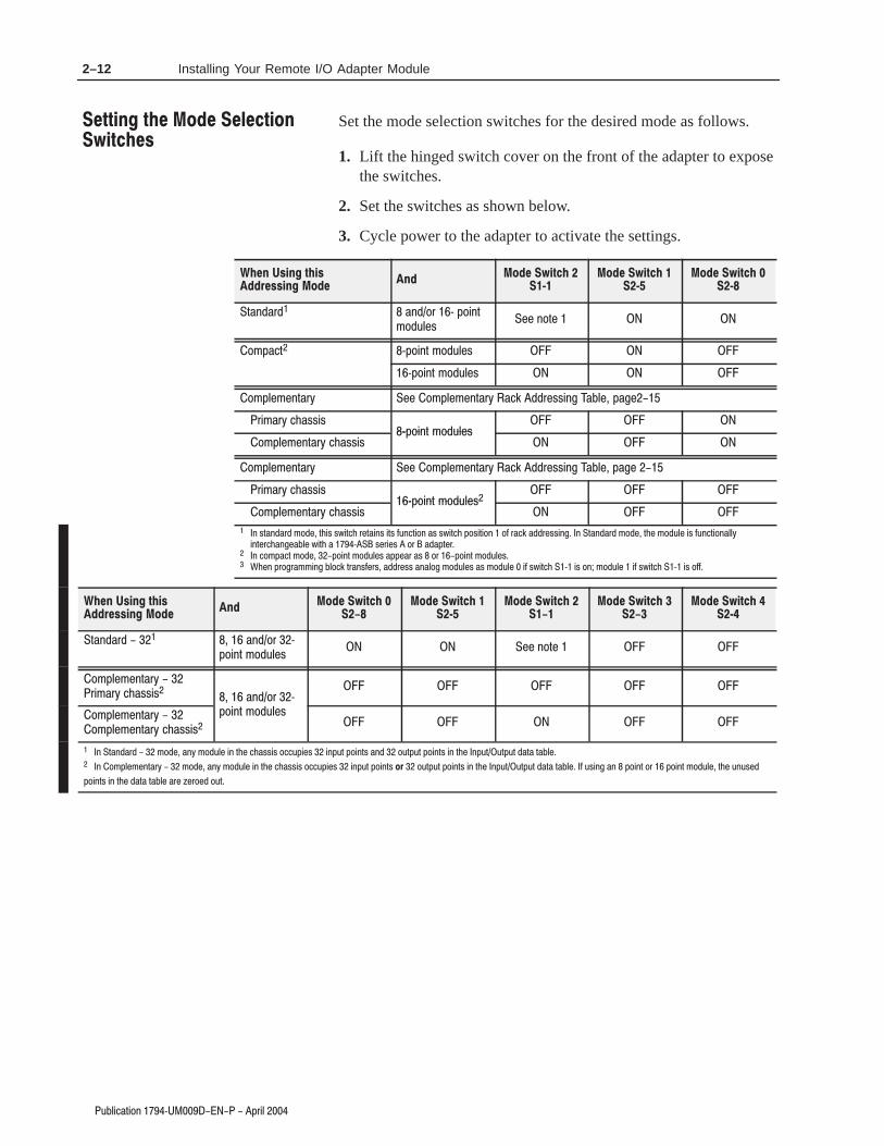
Set the mode selection switches for the desired mode as follows.
1. Lift the hinged switch cover on the front of the adapter to exposethe switches.
2. Set the switches as shown below.
3. Cycle power to the adapter to activate the settings.
2!-$!0$ !-$.0 7 /.)-2
,.$3+%1%% -.2%
.,/!#2 7/.)-2 ,.$3+%1
7/.)-2 ,.$3+%1
.,/+%,%-2!05 %% .,/+%,%-2!05 !#* $$0%11)-' !"+% /!'%
0),!05 #(!11)17/.)-2 ,.$3+%1
.,/+%,%-2!05 #(!11)17/.)-2 ,.$3+%1
.,/+%,%-2!05 %% .,/+%,%-2!05 !#* $$0%11)-' !"+% /!'%
0),!05 #(!11)17/.)-2 ,.$3+%1
.,/+%,%-2!05 #(!11)17/.)-2 ,.$3+%1
- 12!-$!0$ ,.$% 2()1 14)2#( 0%2!)-1 )21 &3-#2).- !1 14)2#( /.1)2).- .& 0!#* !$$0%11)-' - 2!-$!0$ ,.$% 2(% ,.$3+% )1 &3-#2).-!++5
)-2%0#(!-'%!"+% 4)2( ! 7 1%0)%1 .0 !$!/2%0 - #.,/!#2 ,.$% /.)-2 ,.$3+%1 !//%!0 !1 .0 /.)-2 ,.$3+%1 (%- /0.'0!,,)-' "+.#* 20!-1&%01 !$$0%11 !-!+.' ,.$3+%1 !1 ,.$3+% )& 14)2#( 7 )1 .- ,.$3+% )& 14)2#( 7 )1 .&&
2!-$!0$ !-$.0 7
/.)-2 ,.$3+%1 %% -.2%
.,/+%,%-2!05
0),!05 #(!11)1 !-$.0 7
.,/+%,%-2!05
.,/+%,%-2!05 #(!11)1
/.)-2 ,.$3+%1
- 2!-$!0$ ,.$% !-5 ,.$3+% )- 2(% #(!11)1 .##3/)%1 )-/32 /.)-21 !-$ .32/32 /.)-21 )- 2(% -/3232/32 $!2! 2!"+%
- .,/+%,%-2!05 ,.$% !-5 ,.$3+% )- 2(% #(!11)1 .##3/)%1 )-/32 /.)-21 .32/32 /.)-21 )- 2(% -/3232/32 $!2! 2!"+% & 31)-' !- /.)-2 .0 /.)-2 ,.$3+% 2(% 3-31%$
/.)-21 )- 2(% $!2! 2!"+% !0% 6%0.%$ .32

2–13Installing Your Remote I/O Adapter Module
+#!*!&% / '(!#
Use the following table to set your address switches. (Refer to page2–15 to set address switches when in complementary mode.)
! "
# # # #
" &* #! " "
" " " "
" " " "
" " " "
" " "
" " "
" " "
" " "
" " "
" " "
" " "
" " "
" " "
" " "
" " "
" " "
" " "
" " "
" " "
" " "
" " "
" " "
" " "
" " "
" "
" "
" "
" "
" "
" "
" "
" "
%&* " ())) * (+ (
&%#. ,!## !% )*%( % )*%(
"
&%#. ,!## !% )*%( % )*%(
$&) "
&%*!%+ &% %-* '
"

2–14 Installing Your Remote I/O Adapter Module
3"+)#!2).- 6 /0)+
!#*
!#*
!#*
!#*
!#*
!#*
!#*
!#*
!#*
!#*
!#*
!#*
!#*
!#*
!#*
!#*
!#*
!#*
!#*
!#*
!#*
!#*
!#*
!#*
!#*
!#*
!#*
!#*
!#*
.2 !+)$
!#* !$$0%11 )1 !- )++%'!+ #.-&)'30!2).-
6 /0.#%11.01 #!- 1#!- 0!#*
6 !-$ 6 /0.#%11.01 #!- 1#!- 0!#*1
6 !-$ 6 /0.#%11.01 #!- 1#!- 0!#*1
6 !-$ 6 /0.#%11.01 #!- 1#!- 0!#*1
6 !-$ 6 /0.#%11.01 #!- 1#!- 0!#*1
6 /0.#%11.01 #!- 1#!- 0!#*1
6 /0.#%11.01 #!- 1#!- 0!#*1
.2% (%- 31)-' ! 6 1%0)%1 .0 +!2%0 !$!/2%0 ,.$3+% 0!#* !$$0%11%1 2. !0% .-+5 !4!)+!"+% )- 2!-$!0$ !-$
2!-$!0$ ,.$%1

2–15Installing Your Remote I/O Adapter Module
#" $ !
Use the following table to set your address switches forcomplementary I/O when using a PLC-5 processor. For all otherprocessors, refer to the programming manual for that specificprocessor.
""'
%" &$ #$
( (
"
!$"'
%" &$ #$
( (
"
In this chapter you learned how to install your adapter module andset your switches. Chapter 3 tells you how to communicate with yoursystem.
$$ $ "##
&$# "
!$"'
!$" %"'

2–16 Installing Your Remote I/O Adapter Module

In this chapter, we tell you about:
• FLEX I/O module data• selecting an addressing type• selecting an addressing mode• determining rack size• mapping data into the image tables• operating modes
There are 2 types of data associated with FLEX I/O modules: inputdata and output data.
• input data – data read from the module by the processor
• output data – data written to the module by the processor
Some digital I/O modules have both input and output data associatedwith them. Digital I/O modules map input data and output data to theinput and output image tables in the processor. Input and output datacan be defined as:
• real I/O data – data that represents the actual state ofhardwired inputs and outputs (input data on input modules,output data on output modules)
• configuration/status data – data written to configure themodule (such as delay times); and status information (such asa fuse blown indication)
For FLEX analog modules, input and output data is only accessibleby the processor using block transfer instructions. The data iscontained in block transfer write (BTW) and block transfer read(BTR) data files, not in the input and output image tables. A byte ofinput image and a byte of output image is required for the modulestatus byte (MSB) and the module control byte (MCB). The MSBuses input image, and the MCB uses output image. These bytes arerequired for block transfer command communications.

3–2 Communicating with FLEX I/O Modules
5#,*$"4*/. ; 02*,
The 1794-ASB series E adapter supports 5 different modes ofaddressing: standard, compact, complementary, standard–32 andcomplementary–32.
For digital modules, the mode of addressing determines what type ofdata is available to the processor from the module.
• standard addressing – input and output data is available for eachdigital module connected to the adapter
• compact addressing – either input or output data (not both) isavailable for each digital module connected to the adapter
• complementary addressing – either input or output data (not both)is available for each digital module connected to the adapter
Analog modules can be used in any mode of addressing with no lossof data because data is not stored in the input and output image table,with the exception of the MCB and MSB. Analog data is stored inBTW and BTR data files.
The following table helps you to select an addressing mode based onthe kind of modules you want to use, and the features you need fromthose modules. The table also lists both advantages anddisadvantages of using each addressing type.
4".%"2% • 9/5 .&&% '5,, -/%5,&
'5.$4*/.",*49 *.$,5%*.( $/-#*."4*/.
-/%5,&3 ; 3&44"#,&
*.054 %&,"9 4*-&3 /. *.054 -/%5,&3
; ; ".% '53& #,/7.
*.%*$"4*/. ; '/2
&8"-0,& *,, 7/2+ 7*4) 04
-/%5,&3 7*4) *. ".% /54
• 3&2 )"3 "$$&33 4/ 7/2% /' *.054
7/2% /' /54054 '/2 &"$) %*(*4", -/%5,&
• *()4 -/%5,&3 &15", ,/(*$", 2"$+
• / 2&342*$4*/.3 /. -/%5,& 0,"$&-&.4
• "8*-5- 53& /' $/.'*(52"4*/.34"453 ".%
$/-#*."4*/. -/%5,&3
• .&''*$*&.4 *-"(& 4"#,&
54*,*:"4*/.
/-0"$4 • 9/5 .&&% '5,, -/%5,&
'5.$4*/.",*49 *.$,5%*.( $/-#*."4*/.
-/%5,&3 ; 3&44"#,&
*.054 %&,"9 4*-&3 /. *.054 -/%5,&3
; ; ".% '53& #,/7.
*.%*$"4*/. ; '/2
&8"-0,&
• 9/5 $". ,/$"4& &15", .5-#&23 /'
*.054 ".% /54054 -/%5,&3 *. " 3*.(,&
$)"33*3
• *()4 0/*.4 -/%5,&3 &15", ,/(*$",
2"$+3 7)&. *.054 ".% /54054 -/%5,&3 "2&
*.34",,&% *. ",4&2."4& 3,/43
• *()4 0/*.4 -/%5,&3 &15", ,/(*$",
2"$+3 7)&. *.054 ".% /54054 -/%5,&3 "2&
*.34",,&% *. ",4&2."4& 3,/43
• 2/6*%&3 -"8*-5- 53& /' *-"(& 4"#,&
#9 " 3*.(,& $)"33*3 7)&. *.054 ".%
/54054 -/%5,&3 "2& *.34",,&% *. ",4&2."4&
3,/43
• !/5 -534 $/.'*(52& ",, -/%5,&3
*. 4)& $)"33*3 "3 &*4)&2 ;0/*.4
/2; 0/*.4
• / $/-#*."4*/. -/%5,&3
",,/7&%
• /.'*(52"4*/.34"453 %"4" *3 ./4
"$$&33*#,& 4/ 53&2

3–3Communicating with FLEX I/O Modules
4"+)#!3).- : /1)+
.,/+%,%-3!18 • 8.4 -%%$ &4++ ,.$4+%
&4-#3).-!+)38 )-#+4$)-' #.,")-!3).-
,.$4+%2 : 2%33!"+%
)-/43 $%+!8 3),%2 .- )-/43 ,.$4+%2
: : !-$ &42% "+.6-
)-$)#!3).- : &.1
%7!,/+%
• 8.4 #!- +.#!3% %04!+ -4,"%12 .&
)-/43 !-$ .43/43 ,.$4+%2 )-
2%/!1!3% #(!22)2
• )'(3 /.)-3 ,.$4+%2 )- %!#( #(!22)2
%04!+ +.')#!+ 1!#* 6(%- )-/43
,.$4+%2 !1% )-23!++%$ )- #(!22)2 !-$
.43/43 ,.$4+%2 !1% )-23!++%$ )- 3(%
#.,/+%,%-3!18 #(!22)2
• )'(3 /.)-3 ,.$4+%2 )- %!#( #(!22)2
%04!+ +.')#!+ 1!#* 6(%- )-/43 ,.$4+%2
!1% )-23!++%$ )- #(!22)2 !-$ .43/43
,.$4+%2 !1% )-23!++%$ )- 3(%
#.,/+%,%-3!18 #(!22)2
• 1.5)$%2 ,!7),4, 42% .& ),!'% 3!"+%
)- #(!22)2 6(%- )-/43 ,.$4+%2
!1% )-23!++%$ )- #(!22)2 !-$ .43/43
,.$4+%2 !1% )-23!++%$ )- 3(%
#.,/+%,%-3!18 #(!22)2
• .4 ,423 #.-&)'41% !++ ,.$4+%2
)- ".3( #(!22)2 !2 %)3(%1 :/.)-3
.1 :/.)-3
• . #.,")-!3).- ,.$4+%2
!++.6%$
• .-&)'41!3).-23!342 $!3! )2 -.3
!##%22)"+% 3. 42%1
3!-$!1$ • 8.4 -%%$ &4++ ,.$4+%
&4-#3).-!+)38 )-#+4$)-' /.)-3
,.$4+%2 #.,")-!3).- ,.$4+%2
: 2%33!"+% )-/43
$%+!8 3),%2 .- )-/43 ,.$4+%2
: : !-$ &42% "+.6-
)-$)#!3).- : &.1
%7!,/+%
• 2%1 (!2 !##%22 3. 6.1$2 .& )-/43
6.1$2 .& .43/43 &.1 %!#( $)')3!+ ,.$4+%
• .41 ,.$4+%2 %04!+ +.')#!+ 1!#*
• . 1%231)#3).-2 .- ,.$4+% /+!#%,%-3
• !7),4, 42% .& #.-&)'41!3).-23!342 !-$
#.,")-!3).- ,.$4+%2
• -%&&)#)%-3 ),!'% 3!"+%
43)+)9!3).-
.,/+%,%-3!18 • 8.4 -%%$ &4++ ,.$4+%
&4-#3).-!+)38 )-#+4$)-' #.,")-!3).-
,.$4+%2 : 2%33!"+%
)-/43 $%+!8 3),%2 .- )-/43 ,.$4+%2
: : !-$ &42% "+.6-
)-$)#!3).- : &.1
%7!,/+%
• 8.4 #!- +.#!3% %04!+ -4,"%12 .&
)-/43 !-$ .43/43 ,.$4+%2 )-
2%/!1!3% #(!22)2
• )'(3 ,.$4+%2 )- %!#( #(!22)2 %04!+
+.')#!+ 1!#*2
• 1.5)$%2 ,!7),4, 42% .& ),!'% 3!"+%
)- #(!22)2 6(%- )-/43 ,.$4+%2
!1% )-23!++%$ )- #(!22)2 !-$ .43/43
,.$4+%2 !1% )-23!++%$ )- 3(%
#.,/+%,%-3!18 #(!22)2
• ++ $)')3!+ ,.$4+%2 !1%
#.-&)'41%$ !2 :/.)-3
• . #.,")-!3).- ,.$4+%2
!++.6%$
• .-&)'41!3).-23!342 $!3! ,!8
-.3 "% !##%22)"+% 3. 42%1
$%/%-$)-' .- ,.$4+% 38/%
The amount of data accessible to the processor in the 5 addressingmodes is illustrated below. Note that the shaded areas represent datanot accessible by the processor.
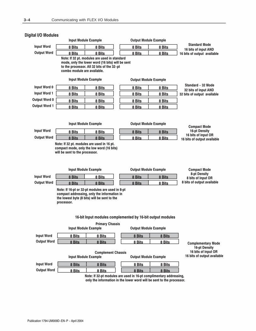
3–4 Communicating with FLEX I/O Modules
')-, (*
-,)-, (*
,'* (
')-, (*
-,)-, (*
(&), (
2), '+$,1
$,+ (! $')-,
$,+ (! (-,)-, .$%%
')-, (*
-,)-, (*
$,+ $,+
$,+ $,+
$,+ $,+
$,+ $,+
$,+ $,+
$,+ $,+
$,+ (! $')-,
$,+ (! (-,)-, .$%%
$,+ $,+
$,+ $,+
$,+ $,+
$,+ $,+
$,+ $,+
$,+ $,+
')-, (-% 0&)% -,)-, (-% 0&)%
$"$,% (-% +
(&), (
2), '+$,1
$,+ (! $')-,
$,+ (! (-,)-, .$%%
(, ! 2), (* 2), &(-% + * -+ $' 2),
(&), * ++$'" ('%1 ,# $'!(*&,$(' $'
,# %(/ +, 1, $,+ /$%% + ', ,( ,#
)*( ++(*
')-, (*
')-, (*
,'* ( $,+ $,+
$,+ $,+
$,+ (! $')-,
$,+ (! (-,)-, .$%%
$,+ $,+
$,+ $,+
')-, (-% 0&)% -,)-, (-% 0&)%
-,)-, (*
-,)-, (*
$,+ $,+
$,+ $,+
$,+ $,+
$,+ $,+
')-, (-% 0&)% -,)-, (-% 0&)%
(, ! ), &(-% + * -+ $' +,'*
&( ('%1 ,# %(/ * /(* $,+ /$%% + ',
,( ,# )*( ++(* %% $,+ (! ,# ),
(&( &(-% * .$%%
(, ! ), &(-% + * -+ $' ),
(&), &( ('%1 ,# %(/ /(* $,+
/$%% + ', ,( ,# )*( ++(*
')-, (-% 0&)% -,)-, (-% 0&)%
')-, (*
-,)-, (*
$,+ $,+
$,+ $,+
$,+ $,+
$,+ $,+ (&)% & ',*1 (
2), '+$,1
$,+ (! $')-,
$,+ (! (-,)-, .$%%
')-, (*
-,)-, (*
$,+ $,+
$,+ $,+
$,+ $,+
$,+ $,+
*$&*1 #++$+
(&)% & ', #++$+
2$, ')-, &(-% + (&)% & ', 1 2$, (-,)-, &(-% +
(, ! 2), &(-% + * -+ $' 2), (&)%$& ',*1 * ++$'"
('%1 ,# $'!(*&,$(' $' ,# %(/ * /(* /$%% + ', ,( ,# )*( ++(*
')-, (-% 0&)% -,)-, (-% 0&)%
')-, (-% 0&)% -,)-, (-% 0&)%

3–5Communicating with FLEX I/O Modules
). # , - , *, - (. . (). --$& 3 .# *,) --),
(*/. ),
/.*/. ),
$.- $.-
$.- $.-
$.- $.-
$.- $.- )'*& ' (.,3 )
4*. (-$.3
$.- )! $(*/.
$.- )! )/.*/. 0$&&
(*/. ),
/.*/. ),
$.- $.-
$.- $.-
$.- $.-
$.- $.-
,$',3 #--$-
)'*& ' (. #--$-
4$. (*/. ')/& - )'*& ' (. 3 4$. )/.*/. ')/& -
(*/. ),
(*/. ),
)'*& ' (.,3 )
*. (-$.3 $.- $.-
$.- $.- $.- )! $(*/.
$.- )! )/.*/. 0$&&
(*/. )/& 2'*& /.*/. )/& 2'*&
/.*/. ),
/.*/. ),
$.- $.-
$.- $.-
(*/. ),
(*/. ),
)'*& ' (.,3 )
$.- )! $(*/.
$.- )! )/.*/. 0$&&
$.- $.-
$.- $.-
(*/. )/& 2'*& /.*/. )/& 2'*&
/.*/. ),
/.*/. ),
$.- $.-
$.- $.-
)'*& ' (. #--$-
,$',3 #--$-
$.-
$.-
$.-
$.-
$.- $.-
$.- $.-
$.- $.-
$.- $.-
$.- $.-
$.- $.-
). ! 4*. ), 4*. ')/& - , /- $( 4*. )'*& ' (.,3 , --$("
)(&3 .# $(!),'.$)( $( .# &)1 -. 3. 1$&& - (. .) .# *,) --),
(*/. )/& 2'*& /.*/. )/& 2'*&
(*/. )/& 2'*& /.*/. )/& 2'*&
4$. (*/. ')/& - )'*& ' (. 3 4$. )/.*/. ')/& -
Analog modules use block transfers, which require 1 byte (8 bits) ofinput image for the module status byte, and 1 byte (8 bits) of outputimage for the module control byte. This is true for any addressingmode selected.
(*/. ),
/.*/. ),
(3 )
&)% .,(-! ,- , +/$,
$.- )! $(*/. $'" (
$.- )! )/.*/. $'"
$.-
$.-
(*/. ), /.*/. 2'*&
(&)" &)% ,(-! ,
)/& -

3–6 Communicating with FLEX I/O Modules
2"*)#!1)-, 6 ./)*
Use standard addressing when:
• you need full FLEX I/O module functionality, such as delay timeselection on input modules, fuse-blown indication on the1794-OB8EP, etc.
• using combination modules, such as the 1794-IB10XOB6 10 in/6out module
In standard mode, each module position equals one I/O group – 1word of input image and 1 word of output image. If 32-pt input oroutput modules are used, only the lower 16 bits are available. All 32bits of the 32–pt combination modules are available.
,5 #-+"),!1)-, -& $)')1!* -/ !,!*-' +-$2*%0
)'(1 1%/+),!* "!0%0 .%/ !$!.1%/ +!4)+2+$!.1%/
!#( 1%/+),!* "!0% /%./%0%,10 '/-2.
,.21 21.21 ,.21 21.21 ,!*-' ,!*-' 21.21 ,.21
*%( ())!%
(&+'
%'+* $ # +*'+* $ #
,.21 -3 51%
,.21 )'( 51%
21.21 -3 51%
21.21 )'( 51%
-$2*% -,1/-* 51% -21.21 $!1!
-$2*% 1!120 51% ),.21 $!1!
6
6
6
6
6
6
6
6
6
6
*%( ())!% ,$'#
/-2. /-2. /-2. /-2.
$&+#) #& !# (" (&+')
/-2. /-2. /-2. /-2.
6
66
6
6
6
6
6
66 66
6666
6 6
$&+# '&)!*!&% !) % (&+'
# &+# #$%* !% *%( ())!%
,5 +-$2*% ), !,5 0*-1
*%( ())!%

3–7Communicating with FLEX I/O Modules
3#+*$"2*.- 7! /0*+
Use standard 32 point addressing when:
• you use 32 point modules in your system
• you need full FLEX I/O module functionality, such as delay timeselection on input modules, fuse-blown indication on the1794-OB8EP, etc.
• using combination modules, such as the 1794-IB16XOB16 16in/16 out module
In standard – 32 mode, each module position equals two I/O groups– 2 words of input image and 2 words of output image.
0.3/
-/32 ,!'% !"+% &.0 !#* 32/32 ,!'% !"+% &.0 !#*
*21 2)03 '.0 *-/32 "-% .32/32 4.0%1 .' /.*-2 ,.%3+&1
*21 2)03 '.0 *-/32 "-% .32/32 4.0%1 .' /.*-2 ,.%3+&1
*21 2)03 '.0 *-/32 "-% .32/32 4.0%1 '.0 "-% /.*-2 ,.%3+&1
*21 2)03 '.0 *-/32 "-% .32/32 4.0%1 '.0 /.*-2 ,.%3+&1
.%3+& .-20.+ 62& .32/32 %"2"
.%3+& 2"231 62& *-/32 %"2"
7
7
7
7
7
7
7
2!-$!0$ $$0%11)-' 6!,/+% ,.$3+%1 +.')#!+ 0!#*1 !-$ '0.3/1
0
7
7
7
7
7
7
7 7777
777777
77
,.$3+% /.1)2).- )1 '0.3/1
%'!+ .$3+% +!#%,%-2 )- 2!-$!0$ $$0%11)-'
-6 ,.%3+& *- "-6 1+.2
*()2 2&0,*-"+ #"1&1 /&0 "%"/2&0 ,"5*,3,
"$) 2&0,*-"+ #"1& 0&/0&1&-21 (0.3/1
*21 2)03 '.0 *-/32 "-% .32/32 4.0%1 .' /.*-2 ,.%3+&1
*21 2)03 '.0 *-/32 "-% .32/32 4.0%1 .' /.*-2 ,.%3+&1
77
77
77
77
77
77
77
77
77
77
77
77
0.3/ 0.3/
0.3/ 0.3/
0.3/
-/32 ,!'% !"+% &.0 !#* 32/32 ,!'% !"+% &.0 !#*
7
7
7
7
7
7
7
7
7
7
7
7
7
7
7
7
7
7
7
7
7
7
7
7
7
7
7
7
7
7
7
7
7
7
7
7
7
7
7 7777
777777
77
77
77
7
77
77
77
77
77
77
77
77
0.3/
0.3/
-/32 ,!'% !"+% &.0 !#* 32/32 ,!'% !"+% &.0 !#*
7
7
7
7
7
7
7
7
7
7
7
0 0 0 0 0 0 0 0 0 0 0 0 0 0 0
.2% (!$%$ !0%!1 0%/0%1%-2 $!2! 5()#( )1 -.2 !4!)+!"+%
!#* !#*
-"+.( -"+.(
7
7
2!-$!0$ $$0%11)-'

3–8 Communicating with FLEX I/O Modules
Use compact addressing when:
• you are not using combination modules
• you are using only digital input, digital output and analogmodules
• you don’t need all the features of digital FLEX I/O modules (Youcan only access the input word on an input module, or the outputword of an output module. Any status information/configurationinformation in the corresponding input/output word is notaccessible.)
• you can locate equal numbers of input and output modules in asingle chassis
• you want more efficient use of the input/output data table
Compact mode maximizes single chassis I/O image table usage whenusing either 8- or 16-point modules and block transfer modules.
Compact mode allows more than 1 module to occupy a single I/Ogroup. How many modules depends on the density selected (16- or8-point).
In compact mode, with 16-point density, 2 digital modules (1 inputand 1 output module) can occupy 1 I/O group. In addition, 2 blocktransfer modules can occupy 1 I/O group. If higher density modulesare used, only the lowest 16 bits will be available.
In compact mode, with 8-point density, 4 digital modules (2 inputand 2 output modules) mounted in module pairs can occupy 1 I/Ogroup. In addition, 2 block transfer modules can occupy 1 I/O group.If higher density modules are used, only the lowest 8 bits will beavailable.

3–9Communicating with FLEX I/O Modules
!7&/-'%6-21 <#! 34-/
1376 02(7/)5 %1( 76376 02(7/)5 -1 3%-45 24 %1%/2+ 02(7/)5
-+,6 6)40-1%/ &%5)5 3)4 %(%36)4 0%9-070(%36)4
%', 02(7/) 4)34)5)165 2* %1 +4273
4273 4273 4273 4273
1376 76376 1376 76376 76376 13761%/2+ 1%/2+
3,+&*/ +), / !!-"..&*$
02(7/)5 4)34)5)16 +4273
02(7/)5 4%'.
-+0,
*,0/ )$" (" 0/,0/ )$" ("
1376 28 :6)
1376 -+, :6)
76376 28 :6)
76376 -+, :6)
2(7/) 21642/ :6) 276376 (%6%
" 2(7/) "6%675 :6) -1376 (%6%
"
<
<
<"
<
<
<
<"
<
<
<
<
<
<
<
<
<
+), / 3,+&*/ !!-"..&*$ 2),("
4273 4273 4273 4273
)+!0(". (+$& ( - ' $-+0,.
)+!0(" ,+.&/&+*. * $-+0,
"$( +!0(" ( ")"*/ &* 3,/ +), / !!-"..&*$
<32-16 -1376 02(7/) %1( % <32-16 276376 02(7/)
24 %1 )036: 5/26 -1 %1 +4273
+/" %!"! -". -",-"."*/ 0*1&((" !/
$-+0,. -" 1&((" #+- *+/%"- !,/"-
+/" $,)1 75-1+ &/2'. 64%15*)4 02(7/)5 -1 <36 '203%'6 %((4)55-1+ %((4)55 02(7/) 325-6-215
%1( %5 02(7/) ; -1 % &/2'. 64%15*)4 -15647'6-21 &/2'. %((4)55 02(7/) 325-6-215
%1( %5 02(7/) ; -1 % &/2'. 64%15*)4 -15647'6-21 &/2'.
<36 276376 02(7/) %1( % <36 -1376 02(7/)
24 %1 )036: 5/26 -1 %1 +4273
&/2'. 64%15*)4 02(7/) 8-6, %126,)4 &/2'. 64%15*)4 02(7/)
24 %1 )036: 5/26 -1 %1 +4273
1 )036: 5/26 8-6, %1: 02(7/) 24 %126,)4 )036:
5/26 -1 %1 +4273

3–10 Communicating with FLEX I/O Modules
6%.,&$5,10 :" 23,.
0265 /1'6.(4 $0' 65265 /1'6.(4 ,0 5+( 4$/( *3162
,*+5 5(3/,0$. %$4(4 2(3 $'$25(3 /$8,/6/'$25(3
$&+ /1'6.( 3(23(4(054 1) $0 *3162
3162 3162
0265 65265 0265 65265 65265 0265
1*)$(- )'*- +!,,$(" $"$-& ) .&!,
/1'6.(4 3(23(4(05 *3162
026565265
+).*
(*.- '"! &! .-*.- '"! &!
0265 17 95(
0265 ,*+ 95(
65265 17 95(
65265 ,*+ 95(
:
:
:
:
:
:
:
:
#
)'*- 1*)$(- +!,,$(" 0'*&! $"$-& ') .&!, &)"$& +%
3162 3162
#
') .&! *),$-$)(, -) ( "+).*
!"& ) .&! &!'!(- $( 1*)$(- )'*- +!,,$("
!71 :21,05 ,0265 /1'6.(4 $0' 571 :21,05 165265 /1'6.(4 13 (/259
4.154 ,0 $0 *3162 1'6.( 592( /645 $.5(30$5( 7,5+,0 $0 *3162
,0265 165265 (5&
)-! # ! +!, +!*+!,!(- .(/$&&! -
"+).*, +! /$&&! -) $-$)(& *-!+,
0( %.1&- 53$04)(3 /1'6.( 7,5+ (/259 4.154
0( %.1&- 53$04)(3 /1'6.( )1..17(' %9 $0 (/259 4.15 $015+(3
%.1&- 53$04)(3 /1'6.( $0' $015+(3 (/259 4.15

3–11Communicating with FLEX I/O Modules
6$.+%#5+10 :! 23+.
0#.1) /1&6.'4 +0 5*' 4#/' )3162
+)*5 5'3/+0#. $#4'4 2'3 #'3 /#7+/6/'3
#%* /1&6.' #0& #&,#%'05 '/258 $#4' 3'23'4'054 1( #0 )3162
3162 3162
2+*%). *(+. ,!--%)# )'*# * /'!-
'3
0#.1) /258 0#.1) /258 0#.1) /258 0#.1) /258
,*/+
)+/. (#! '! /.+/. (#! '!
1&6.' 10531. 85' 165265 #
1&6.' 5#564 85' +0265 #
:
:
:
:
*(+. 2+*%). ,!--%)# 1(+'!
3162 3162
)'*# (* /'!- '*#%' ,& #,*/+-
(* /'! +*-%.%*)- ) #,*/+
!#' * /'! '!(!). %) 2+. *(+. ,!--%)#
:21+05 +0265 /1&6.' #0& # :21+05 165265 /1&6.'
13 #0 '/258 4.15 +0 #0 )3162
*.! $ ! ,!- ,!+,!-!). /)0%''! .
#,*/+- ,! 0%''! "*, )*.$!, +.!,
*.! "*'0 64+0) $.1%- 53#04('3 /1&6.'4 +0 :25 %1/2#%5 #&&3'44+0) #&&3'44 /1&6.' 214+5+104
#0& #4 /1&6.' 9 +0 # $.1%- 53#04('3 +04536%5+10 $.1%- #&&3'44 /1&6.' 214+5+104
#0& #4 /1&6.' 9 +0 # $.1%- 53#04('3 +04536%5+10 $.1%-
0 '/258 4.15 #0& #08 /1&6.' 13 #015*'3 '/258 4.15
+0 #0 )31612
$.1%- 53#04('3 /1&6.' #0& #015*'3 $.1%- 53#04('3 /1&6.'
13 #0 '/258 4.15 +0 #0 )3162
:
:
:
:

3–12 Communicating with FLEX I/O Modules
3"+)#!2).- 7 /0)+
Use complementary addressing when:
• you are not using combination modules
• you don’t need all the features of FLEX I/O modules
• you can locate equal numbers of input and output modules inseparate chassis
• you want more efficient use of the input/output image table
Complementary mode maximizes 2 chassis I/O image table usagewhen input modules are installed in 1 chassis, and output modulesare installed in another chassis. This mode allows 2 modules tooccupy a single I/O group.
In complementary mode, with 16-point density, 1 digital inputmodule in the primary chassis, and 1 digital output module in thecomplementary chassis, or vice versa, form an I/O group. Inaddition, analog modules can be complemented by another analogmodule or an empty base. If 32-pt modules are used, only the lowest16 bits will be available.
-6 #.,")-!2).- .& $)')2!+ .0 !-!+.' ,.$3+%1
$!/2%0 -/32
.,/+%,%-2 .& ,.$3+%1 )- /0),!06 #(!11)1 .0 !-!+.' .0 %,/26 &.0 !-!+.'
)'(2 2%0,)-!+ "!1%1 /%0 !$!/2%0 ,!5),3,
$!/2%0
,.$3+%1 )- /0),!06 !-$ )- #.,/+%,%-2 0%/0%1%-2 '0.3/
32/32 ,/26 -!+.'
-!+.' -!+.'-/32 -/32 32/32 -/32
32/32 32/32 32/32 32/32
0.3/ 0.3/ 0.3/ 0.3/ 0.3/ 0.3/ 0.3/ 0.3/
,/26
-/32
(%- /0.'0!,,)-' "+.#* 20!-1&%01 !$$0%11 !-!+.' ,.$3+%1 !1 ,.$3+% )& 14)2#( 7 )1 .- ,.$3+% )& 14)2#( 7 )1 .&&
7
7

3–13Communicating with FLEX I/O Modules
3"+)#!2).- 6 /0)+
1/40
.043 -"(& "#,& 43043 -"(& "#,&
-/32 .4 52%
-/32 )'( 52%
32/32 .4 52%
32/32 )'( 52%
.$3+% .-20.+ 52%
.$3+% 2!231 52%
9 9 9 9 9 9 9 9
0),!05
.,/
,/25
6
6
6
6
66
66
66
66
66
66
6
,/25
66
666
66
6 6
6666
6 66 6
/-0,&-&.3"17 90/*.3 %%1&22*.( 6"-0,&
0.3/
0 3/ -/%4,&2 ,/(*$", 1"$+
&(", /%4,& ,"$&-&.3 *. 90/*.3 /-0,&-&.3"17
-5 ,.$3+% .0 %,/25 1+.2 )- !-5 /.1)2).- .& 2(%
/0),!05 #(!11)1 )-/32 ,.$3+%1 #.,/+%,%-2%$ "5
.32/32 ,.$3+%1 .0 %,/25 1+.21 .32/32 ,.$3+%1
#.,/+%,%-2%$ "5 )-/32 ,.$3+%1 .0 %,/25 1+.21 "+.#*
20!-1&%0 ,.$3+%1 #.,/+%,%-2%$ "5 "+.#* 20!-1&%0
,.$3+%1 .0 %,/25 1+.21 .0 %,/25 1+.21
#.,/+%,%-2%$ "5 )-/32 .32/32 .0 %,/25 1+.21
6 66
6
66 66
/3& )"%&% "1&"2 1&01&2&.3 4."5"*,"#,& %"3"
/3& !)&. 01/(1"--*.( #,/$+ 31".2'&1 *.2314$3*/.2 "%%1&22 ".",/( -/%4,&2 *. 3)& 01*-"17 1"$+ "2 -/%4,&
8 ".% ".",/( -/%4,&2 *. 3)& $/-0,&-&.3"17 1"$+ "2 -/%4,& 8
/-0,&-&.3"17 /%& 90/*.3
Complementary mode maximizes chassis I/O image table usagewhen input modules are installed in one chassis, and output modulesare installed in a complementary chassis. This allows four modulesto occupy a single I/O group.
In complementary mode, with 8-point density, 2 digital inputmodules in the primary chassis, and 2 digital output modules in thecomplementary chassis, or vice versa, form an I/O group. Inaddition, analog modules must be complemented by an empty base.If higher density modules are used, only the lowest 8 bits will beavailable.

3–14 Communicating with FLEX I/O Modules
5$-+%#4+0/ 9" 12+-
/8 %0.$+/#4+0/ 0( &+)+4#- 02 #/#-0) .0&5-'3
'2
/154
0.1-'.'/4 0( .0&5-'3 +/ 12+.#28 %*#33+3 02 '.148 (02 #/#-0)
+)*4 4'2.+/#- $#3'3 1'2 #'2 .#7+.5.
'2
052 .0&5-'3 +/ 4*' 12+.#28 #/& +/ 4*' %0.1-'.'/4 2'12'3'/43 )2051
54154 .148.148
)'*&!'!(-+1
+$'+1
/#-0)/#-0)/154 /154 /154 /154 /154
54154 54154 54154 54154 54154
2051 2051 2051 2051
2*)$(- )'*&!'!(-+1 +!,,$("
+).*
(*.- '"! &! .-*.- '"! &!
/154 06 84'
/154 +)* 84'
54154 06 84'
54154 +)* 84'
0&5-' 0/420- 84'
! 0&5-' !4#453 84'
!
2 2 2 2 2 2 2 2
!
2+.#28
0.1
9
9
9!
99
9
9
9!
99
99
99
9
9
99
99
9
9
.148 .148
)'*&!'!(-+1 2*)$(- +!,,$(" 0'*&!
2051
.* -) $"$-& )+ (&)" ') .&!, &)"$& +%
+/1543 +/ # )2051 %0.1-'.'/4'& $8 0541543 02 '.148 3-043
0541543 +/ # )2051 %0.1-'.'/4'& $8 +/1543 02 '.148 3-043
$-0%, 42#/3('2 .0&5-'3 %0.1-'.'/4'& $8 '.148 3-043
$-0%, 42#/3('2 .0&5-' #/& +/154 +/ # )2051 %0.1-'.'/4'&
$8 '.148 3-04 #/& 054154 .0&5-'
!"& ) .&! &!'!(- $( 2*)$(- )'*&!'!(-+1
)-! # ! +!, +!*+!,!(- .(/$&&! -
"+).*, +! /$&&! -) $-$)(& *-!+,
.148 3-043 %0.1-'.'/4'& $8 #/ '.148 3-04 +/154 02 054154 3-04

3–15Communicating with FLEX I/O Modules
5$-+%#4+0/ 9" 12+-
Use complementary 32 point addressing when:
• you use 32 point modules in your system• you need full FLEX I/O module functionality, such as delay time
selection on input modules, fuse-blown indication on the1794-OB8EP, etc.
• using combination modules, such as the 1794-IB16XOB16 16in/16 out module
In complementary mode, each module position equals two I/Ogroups – 2 words of input image and 2 words of output image.
0.3/
+43 4*25 (02 +/154 #/& 054154 602&3 0( 10+/4 .0&5-'3
+43 4*25 (02 +/154 #/& 054154 602&3 0( 10+/4 .0&5-'3
+43 4*25 (02 +/154 #/& 054154 602&3 (02 #/& 10+/4 .0&5-'3
+43 4*25 (02 +/154 #/& 054154 602&3 (02 10+/4 .0&5-'3
9
9
9
9
9
9
9
.,/+%,%-2!06 $$0%11)-' 5!,/+% ,.$3+%1 +.')#!+ 0!#*1 !-$
9
9
9
9
9
9
9 9999
999999
99
/8 .0&5-' +/ #/8 3-04 +/ 12+.#28 %*#33+3 0.1-'.'/4 0( 12+.#28
%*#33+3 .0&5-' +/ %0.1-'.'/4#28 %*#33+3 3-04
+)*4 4'2.+/#- $#3'3 1'2 #'2 .#7+.5.
.0&5-' +/ 12+.#28 %*#33+3 .0&5-' +/ %0.1-'.'/4#28
%*#33+3 2'12'3'/43 )20513
+43 4*25 (02 +/154 #/& 054154 602&3 0( 10+/4 .0&5-'3
+43 4*25 (02 +/154 #/& 054154 602&3 0( 10+/4 .0&5-'3
99
99
99
99
99
99
99
99
0.3/ 0.3/
0.3/ 0.3/
0.3/
-/32 ,!'% !"+% &.0 !#* !-$ 32/32 ,!'% !"+% &.0 !#* !-$
9
9
9
9
9
9
9
9
9
9
9
9
9
9
9
9
9
9
9
9
9
9
9
9
9
9
9
99
9!
99
99
99
99
0.3/
-/32 ,!'% !"+% &.0 !#* !-$
9
9
9
9
!
7 7 7 7 7 7 7 7
!
2+.#28
0.1
2051
%'!+ .$3+% +!#%,%-2 )- 7/.)-2 .,/+%,%-2!06
/154 54154 .148
54154
54154 /154 /#-0) /#-0)54154
54154 /154 54154 /154 .148 /#-0) /154
9
9
99
9
99
99
99
99
0.3/
32/32 ,!'% !"+% &.0 !#* !-$
9
9
9
9
/8 +/154 .0&5-' %0.1-'.'/4'& $8 #/ 054154 .0&5-' 02 '.148 3-04
/8 054154 .0&5-' %0.1-'.'/4'& $8 #/ +/154 .0&5-' 02 '.148 3-04
/8 $-0%, 42#/3('2 .0&5-' %0.1-'.'/4'& 6+4* # $-0%, 42#/3('2
.0&5-' 02 '.148 3-04
/ '.148 3-04 %0.1-'.'/4'& $8 #/ '.148 3-04 +/154
02 054154 .0&5-'.2% (!$%$ !0%!1 0%/0%1%-2 3-!4!)+!"+% $!2!
9!9!
9 9
9
2051 2051 2051 2051 2051 2051 2051
!#* !#*
!#* !#*
.,/+%,%-2!06
$$0%11)-'

3–16 Communicating with FLEX I/O Modules
After the rack size has been determined by the remote I/O adapter,the data from the modules must be mapped into the data tables. Dataassociated with digital modules is mapped into the input and outputimage table.
Data transfer to and from the remote I/O adapter and digital modulesoccurs every flexbus scan. This data is mapped into the input/outputimage table.
IMPORTAN TThe switch settings on the adapter moduledetermine whether both the input and output bitsare transferred. Standard addressing is the onlymode that maps both input and output bits foreach module.
For analog modules, only the MSB and MCB block transfer bytesare mapped into the input and output image table. The remote I/Oadapter transfers data to analog I/O modules (block transfer write)and from analog I/O modules (block transfer read) using BTW andBTR instructions in your ladder diagram program. This data ismapped to the data files selected in the ladder logic block transferinstructions.
The adapter identifies the type of module in each base unit when themodule is added, and stores this information for later use, ifnecessary.
IMPORTANTIf you are changing your configuration, youmust power down, then power back up afterchanging a module type in a terminal base unit.
ATTENTION
!In Standard Addressing Mode, FLEX I/O modulesdo not support complementary I/O. Do notattempt to use the complementary image tableword of a module in Standard Addressing Mode.The complementary word is reserved for use bythe module.
After the remote I/O adapter has identified the modules present in itssystem, it creates a “rack image” so data transfer can take place usingthe remote I/O protocol.
Building a rack image consists of:• mapping each module to an I/O group (16 bits of input and 16
bits of output)
• determining rack size – all empty terminal bases are countedunless they occur at the end of the rack
• automatically sizing the rack image, based upon the mode switchsetting

3–17Communicating with FLEX I/O Modules
%$ ' !"
• smallest rack size is 1/4, regardless of the mode switch settings
Some examples of rack definition are shown below.
!$"
% " ! $ )$' #% $. $( ). %' $"% #%*" # -
%*" %*" %*" %*"
-#&" '# $" (( %*"(
! $ %#&) #% , ) 0&) #%*"( ! $ %#&) #% , ) 0&) #%*"(
%*" %*" %*" %*"
% " !( $ )$' #% $. $( ). %' $"% #%*" # -
""&'
!$"
% " ! $ %#&"#$)'. #% 0&) #%*"( &' #'. $&*) #%*"( %#&"#$)
%*)&*) #%*"( $ + +'( $"% %#&"#$) , ) $%)' $"% #%*" %' $ #&). ("%)
! $ %#&"#$)'. #% 0&) #%*"( &' #'. $&*) #%*"( %#&"#$) %*)&*)
#%*"( $ + +'( $"% %#&"#$) , ) $ #&). ("%)
%*" %*" %*" %*"
-#&" '# $" (( %*"( %#&"#$)'. %
%*" %*" %*" %*"
!$
!$"%*" %*" %*" %*" %*" %*" %*" %*"
% " !( $ %#&"#$)'. #% #%*"( )%)" $. $( ).
()
"
! / %' '(( $ %
%*"
%( ) %$)$'
)$' %#&)
%#&)
%#&"#$)
%#&"#$)
%#&"#$)
" " " " " " "
" " " " " " "
" " " " " " "
% " " " " % " " "
" " " " " " "
" " " " " " "
" % " " " " % " "
% "# % " " " % "# % " "

3–18 Communicating with FLEX I/O Modules
If a rack size offset by the selected quarter results in more than a fullrack, the adapter will declare a rack fault and error as indicated.
In 32 point mode, the starting quarter should always be 0 (switchesS1–8 and S1–7 on).
ATTENTION
!Do not use the auto-config feature of 6200software when using a PLC-3 processor with1775-S4A or 1775-S4B scanner modules. If youdo an auto-config for a scanner channelcontaining 1 or more 1794-ASB adapters with thatconfiguration, the adapters may not show up inthe scan list for that scanner channel. Manuallyinsert these adapters into the scan list for thescanner.
Most reset commands are issued by the processor when it is placedin the PROG mode. However, the processor automatically issues aspecial command to any rack declared faulted regardless of theprocessor mode.
When this special command is received by the faulted remote I/Oadapter, and processor restart lockout (PRL) has not been selected,the adapter will:
• continue to read output image data from the link, and queue blocktransfers if MCBs are detected
• reset all bits in the output words of digital modules
• reset all bits in the write words of analog modules up to but notincluding the write words of the safe state values
• assigns safe state values to outputs of analog modules
• issue a reply command
If processor restart lockout (PRL) has been selected, the adapter doesnot update data, does not issue a reply command, and does not clearthe fault.
In this chapter, you learned how to address your I/O, how todetermine rack size, and how the modules are mapped

)"!(!$# , %&!"
In this chapter, we tell you:
• about the indicators on the module front plate
• how to use the indicators for troubleshooting the module
Three conditions can cause the remote I/O adapter to declare acommunication fault.
• no remote I/O (link) communication for more than 100ms
• no commands issued to this address over the remote I/O linkwithin the last 255 link transactions
• communication is lost to a module when Rack Fault Select isenabled
When any of these conditions exist, the adapter will:
• reset all digital outputs or leave them in their last state (dependingon the position of the last state switch, S2-1). Refer to page 2–9for an explanation of analog module responses.
A communication fault will be automatically cleared by a commandfrom the processor if PRL (processor restart lockout) is not selected,or by pressing the reset switch on the front of the module if PRL isselected.
%(& )"(
$" )"(
%(& (!*
$+&
'( +!(
Cycling power to the adapter will also reset faults.However, any queued block transfers will be lost, andall outputs will turn off, regardless of the position of thelast state switch.
The module has indicators on the front plate as shown below. Usethese indicators for troubleshooting the module. The following tablesdescribes problems that may occur, probable causes, andrecommended courses of action.

%"03&1 "4,3
/$", "4,3
%"03&1 $3*5&
!
4–2 Troubleshooting
4#,*$"3*/. 9 01*,
# ! !
! ! #
!
!
" !
'' '' . /1-", /--4.*$"3*/.2430432 &."#,&%
/--4.*$"3*.( 6*3) 2$"..&1/3 "00,*$"#,&
'' '' ,*.+*.( 1/(1"- /1 &23 -/%&
430432 %*2"#,&%
/--4.*$"3*.( 6*3) 2$"..&1
&.%*.( $411&.3 *.043 23"342
#"$+ 3/ 2$"..&1
/3 "00,*$"#,&
'' '' ''/--4.*$"3*/. ,"$+ /'
$/--4.*$"3*/.2
,, -/%4,&2 %*(*3", /430432 *. 3)&
1"$+ '/,,/6 2&33*.(
&'&1 3/ 0"(& '/1 ".",/(
/43043 "$3*/.
&24-& 01/0&1 $/--4.*$"3*/.2 *' ./
01/$&22/1 1&23"13 ,/$+/43
'' ,*.+*.( ",3&1."3&,7
1/$&22/1 ,/$+/43 *. &''&$3
%41*.( $/--4.*$"3*/.2 #7
2$"..&1
430432 '/,,/6 ,"23 23"3& 26*3$)
2&33*.(
/ 1&0,*&2 2&.3 3/ 2$"..&1
1&22 &2&3 #433/. /. '1/.3 /' "%"03&1
-/%4,& /1 $7$,& 0/6&1 ".% 1&24-&
01/0&1 $/--4.*$"3*/.
! !
!
!
"! !
. . '' /*2& 01/#,&-2 /. #42 ,, /430432 /'' /--4.*$"3*/.2 /''7$,& 0/6&1 )*2 '"4,3 *2 " '"3",
'"4,3
. ''
/,,/6*.(
*.+
3"342
*''&1&.3 -/%4,& *.23",,&%
1&0,"$*.( 1&-/5&% -/%4,&
,% *.0432 -"*.3"*.&% 430432 2&3
3/ 8&1/
43/91&2&3 6)&. *.$/11&$3 -/%4,&
*2 1&-/5&% /1 $7$,& 0/6&1 3/
&23"#,*2) .&6 *%&.3*'*$"3*/. '/1
-/%4,&
,*.+*.( '' ./%4,& ./3 1&20/.%*.(
/22*#,7 -/%4,& 1&-/5&%
/%4,& ./3 1&20/.%*.( ,% *.0432
-"*.3"*.&% 430432 2&3 3/ 8&1/
,, /3)&1 -/%4,&2 430432 "$3*5&&0,"$& 2"-& -/%4,& /1 $7$,&
1/$&22/1 *. -/%&
"$+ "4,3 &,&$3 &."#,&%
/22*#,7 -/%4,& 1&-/5&%
4.%&1 0/6&1 .,7 -/%4,&
1&-/5&% *2 "''&$3&%
,, /3)&1 -/%4,&2 430432 "$3*5&
&."#,&%
&.%*.( $411&.3 *.043 23"342 #"$+
3/ 2$"..&1
0 7
0/6&1 3/ &23"#,*2) .&6
*%&.3*'*$"3*/. '/1 -/%4,&

4–3Troubleshooting
6$-+%#5+0/ ;! 13+-
-+/,+/) -+/,+/)0&6-' /05 3'410/&+/)
044+$-9 .0&6-' 3'.07'&
0&6-' /05 3'410/&+/) -& +/1654
.#+/5#+/'& 651654 4'5 50 50 :'30
-- 05*'3 .0&6-'4 651654'1-#%' 4#.' .0&6-' 03 %9%-'
30%'4403 +/ .0&'
#%, #6-5 '-'%5 '/#$-'&
044+$-9 .0&6-' 3'.07'&
6/&'3 108'3 /-9 .0&6-'
3'.07'& +4 #(('%5'&
-- 05*'3 .0&6-'4 651654
&+4#$-'&
'/&+/) %633'/5 +/165 45#564 $#%,
50 4%#//'3
1 9
108'3 50 '45#$-+4* /'8
+&'/5+(+%#5+0/ (03 .0&6-'
-+/,+/) (( -+/,+/)0&6-' /05 3'410/&+/)
044+$-9 .0&6-' 3'.07'&
0&6-' /05 3'410/&+/) -- 0651654
4'5 50
-- 05*'3 .0&6-'4 &+)+5#- 0651654 +/
'1-#%' 4#.' .0&6-' 03 %9%-'
30%'4403 +/ !
#%, #6-5 '-'%5 '/#$-'&
044+$-9 .0&6-' 3'.07'&
6/&'3 108'3 /-9 .0&6-'
3'.07'& +4 #(('%5'&
5*' 3#%, (0--08 4'55+/)
'('3 50 1#)' (03 #/#-0) 065165
#%5+0/
0 3'1-+'4 4'/5 50 4%#//'3
1 9
108'3 50 '45#$-+4* /'8
+&'/5+(+%#5+0/ (03 .0&6-'
(( -+/,+/) +/ 6/+40/ /%033'%5 45#35+/) )3061 /6.$'3
/ / / /%033'%5 $#6& 3#5' 4'55+/)05 #11-+%#$-'
63/ 108'3 0(( '5 " #/&
" %033'%5-9 63/ 108'3 0/
-+/,+/) +/ 4'26'/%'/05*'3 #'3 0/ 5*' -+/, *#4 5*'
4#.' #&&3'44
05 #11-+%#$-'" %033'%5-9 63/ 108'3 0/
-+/,+/) / ((--')#- .0&6-' 1-#%'.'/5 %0.1#%5
#&&3'44+/) .0&' 4'-'%5'&05 #11-+%#$-'
033'%5 .0&6-' 1-#%'.'/5
#/& %9%-' 108'3
#/&0. %%'44 '.039 (#6-5
'4'5 0651654 501
%0..6/+%#5+/) 0/ 3'.05'
-+/,9%-' 108'3 *+4 .#9 /05
%033'%5 (#6-5
(( / (('#& /-9 '.039 (#6-5 0/
108'361 0/-9
651654 3'.#+/ 3'4'5
0..6/+%#5+0/ /'7'3 45#354
%033'%5 (#6-5
( 5*+4 &0'4 /05 %033'%5 5*' (#6-5
3'1-#%' 5*' .0&6-' 8+5* # ,/08/
)00& .0&6-' #/& 3'563/ 5*' $#&
/5'3/#- 8#5%*&0) 5+.'3 5+.'&
065
39 50 3'4'5 0651654 5014
%0..6/+%#5+/) 0/ 5*' 3'.05'
-+/,
)00& .0&6-' #/& 3'563/ 5*' $#&
.0&6-' 50 5*' (#%5039 (03 3'1#+3
In this chapter you learned how to use the indicators on the front ofthe module to troubleshoot your module.

4–4 Troubleshooting

#=,53-+<387 CC' !# 9:35
&23; +.+9</: -+778< ,/ =;/. ?3<2 #C 9:8-/;;8:; &23; +.+9</: -+7 -866=73-+</ ?3<2 * 7</1:+ +7+581
68.=5/; +7. 9837< * 68.=5/;
" +9+-3<A 68.=5/;
#8?/: %=995A 7 8:./: <8 -8695A ?3<2 8? (85<+1/ 3:/-<3>/; A8= 6=;< =;/ + %+0/<A
@<:+ 8? (85<+1/ %( 8: + #:8</-</. @<:+ 8? (85<+1/ #( 98?/: ;=995A <8
98?/: <23; +.+9</:
79=< (85<+1/ $+<371 ( .- 78637+5
79=< (85<+1/ $+71/ ( <8 ( .- 37-5=./; +- :3995/
866=73-+<387 $+</ 4 ,9;
4 ,9;
4 ,9;
7.3-+<8:; #8?/: 1://7
.+9</: -<3>/ 1://7
.+9</: 0+=5< :/.
8-+5 0+=5< :/.
5/@,=; "=<9=< =::/7< 6 6+@36=6
;85+<387 (85<+1/ ( +- ,/<?//7 =;/: 98?/: +7. 05/@,=;
#8?/: 87;=69<387 6 +< ( 6 +< (
#8?/: 3;;39+<387 ) 6+@36=6 ( .-
&2/:6+5 3;;39+<387 &'2: ( .-
7>3:876/7<+5 87.3<387;
"9/:+<371
&/69/:+<=:/
&/;< . "9/:+<371 85.
&/;< . "9/:+<371 :A /+<
&/;< !, "9/:+<371 &2/:6+5 %28-4
<8 ° <8 °
%<8:+1/ &/69/:+<=:/ &/;< , '79+-4+1/. !8789/:+<371 85.
&/;< , '79+-4+1/. !8789/:+<371 :A /+<
&/;< !+ '79+-4+1/. !8789/:+<371 &2/:6+5 %28-4
<8 ° <8 °
$/5+<3>/ =63.3<A &/;< , '79+-4+1/. !8789/:+<371 +69 /+<
<8 787-87./7;371
%28-4
"9/:+<371
!8789/:+<371
&/;< + '79+-4+1/. %28-4
1
1
(3,:+<387 &/;< - "9/:+<371
1 B
% 66=73<A
4( -87<+-< .3;-2+:1/;
4( +3: .3;-2+:1/;
$+.3+</. $ 66=73<A
(6 ?3<2 4B ;37/?+>/ 0:86 B <8 B
& 66=73<A
4( 4B 87 98?/: 98:<;
4( 4B 87 -866=73-+<387; 98:<;

Specifications A–2
[email protected]/-?5:9 GG(!"$ ;=57
&@=31 '=-9>519? 88@95?D
6) 75917591 ! -90 6) 75911-=?4 ! :9 >539-7 ;:=?>
:90@/?10 % 88@95?D
) =8> B5?4 6E >591 B-A1 ! 2=:8 6E ?: !E
85>>5:9> &$%
=:@; 7->> B5?4 -;;=:;=5-?1 19/7:>@=1
9/7:>@=1 'D;1 %-?593 ":91 :;19>?D71
%18:?1 # -.71 17019 := 1<@5A-719? -> >;1/52510 59 ;@.75/-?5:9 G
%18:?1 # :991/?:= $7@3 $-=? "@8.1=
$:B1= :90@/?:=>
*5=1 &5E1
-?13:=D
3-@31 88 8-C58@8 >:650 := >?=-9010 B5=1 =-?10 -? : := 3=1-?1=
59/4 88 59>@7-?5:9 8-C
319/D 1=?525/-?5:9
B419 ;=:0@/? 5> 8-=610
( ( 5>?10 90@>?=5-7 :9?=:7 <@5;819?
( ( 5>?10 2:= 7->> 5A5>5:9 =:@; -90 -E-=0:@> :/-?5:9>
& & 1=?52510 $=:/1>> :9?=:7 <@5;819? 2:= 7->> 5A5>5:9 =:@;
-E-=0:@> :/-?5:9>
C @=:;1-9 (95:9 '+ 5=1/?5A1 /:8;75-9? B5?4
" $:?19?5-77D C;7:>5A1 ?8:>;41=1> $=:?1/?5:9 F9
@=:;1-9 (95:9 ! 5=1/?5A1 /:8;75-9? B5?4
" 90@>?=5-7 85>>5:9>
" 90@>?=5-7 88@95?D
" !1->:9?=:7 -. 90@>?=5-7 %1<@5=1819?>
" 90@>?=5-7 88@95?D
'5/6 @>?=-75-9 %-05:/:88@95/-?5:9> /?/:8;75-9? B5?4
&",& 90@>?=5-7 85>>5:9>
[email protected]/-?5:9> 9>?-77-?5:9 9>?=@/?5:9> "
(>1 ?45> /:90@/?:= /-?13:=D 592:=8-?5:9 2:= ;7-99593 /:90@/?:= =:@?593 %121= ?: ;@.75/-?5:9
G F90@>?=5-7 @?:8-?5:9 *5=593 -90 =:@90593 @5017591> &11 ?41 $=:0@/? 1=?525/-?5:9 7596 -? BBB-./:8 2:= 1/7-=-?5:9> :2 :92:=85?D 1=?525/-?1> -90
:?41= /1=?525/-?5:9 01?-57>

Specifications A–3
9'0.(&8.32 ??# 46.0
"-.7 *59.41*28 .7 .28*2)*) +36 97* .2 438*28.&00= *<4037.:* &81374-*6*7 &7 )*+.2*) '=
9634*&2 #2.32 .6*(8.:*
"-* &'36&83.6* *286&0 )*7 2)9786.*7 0*(86.59*7 (*68.+.*7 8-&8 8-.7 *59.41*28 -&7
'**2 +392) 83 (3140= ;.8- 8-* 77*28.&0 *&08- &2) !&+*8= *59.6*1*287 6*0&8.2, 83 8-*
)*7.,2 &2) (327869(8.32 3+ &8*,36= *59.41*28 .28*2)*) +36 97* .2 438*28.&00= *<4037.:*
&81374-*6*7 ,.:*2 .2 22*< 83 8-.7 .6*(8.:* "-* *<&1.2&8.32 &2) 8*78 6*79087 &6*
6*(36)*) .2 (32+.)*28.&0 6*4368 3
3140.&2(* ;.8- 8-* 77*28.&0 *&08- &2) !&+*8= *59.6*1*287 -&7 '**2 &7796*) '=
(3140.&2(* ;.8-
IMPORTANT '7*6:* 8-* +3003;.2, &)).8.32&0 %32* (*68.+.(&8.32 6*59.6*1*287
• "-.7 *59.41*28 .7 238 6*7.78&28 83 7920.,-8 36 38-*6 7396(*7 3+ #$
6&).&8.32
• "-* 7*(32)&6= 3+ & (966*28 86&27+361*6 7-&00 238 '* 34*2(.6(9.8*)
• "-* 1&6/.2, > .7 83 '* (327.)*6*) >&7 &440.(&'0* 83 .2).:.)9&0
463)9(87
• 59.41*28 3+ 0*77*6 2(03796* "=4* &8.2, 1978 '* .278&00*) .2 &2
*2(03796* 463:.).2, &8 0*&78 4638*(8.32 ;-*2 &440.*) .2 0&77
%32* *2:.6321*287
• "-.7 *59.41*28 1978 '* 43;*6*) '= *2*6,= 0.1.8*) &773(.&8*)
*59.41*28 &7 )*+.2*) .2 ;-*2 &440.*) .2 0&77 %32*
*2:.6321*287
• 63:.7.32 7-&00 '* 1&)* 83 46*:*28 8-* 6&8*) :308&,* +631 '*.2,
*<(**)*) '= 86&27.*28 ).7896'&2(*7 3+ 136* 8-&2 ;-*2 &440.*) .2
0&77 %32* *2:.6321*287

Specifications A–4

2!*(" 1(-, 77 ./(*
Major differences between adapter series are indicated in thefollowing table.
/-"$00-/ "-+. 1(!(*(15 , !$ 20$# 4(1' 7 ./-"$00-/0 ,,-1 !$ 20$# 4(1' 7 ./-"$00-/0
1 ,# /# -#$ , *-&
+-#2*$ /$+-3 * 2,#$/
.-4$/
*-") 1/ ,0%$/0 "-,1(,2$
4'$, !*-") 1/ ,0%$/
+-#2*$ (0 /$+-3$# %/-+
(10 ! 0$
$ 0$0 1- #- !*-") 1/ ,0%$/0 ,# !*-") 1/ ,0%$/ !(1 (0 0$1 4'$, !*-") 1/ ,0%$/
+-#2*$ (0 /$+-3$# %/-+ 1'$ "' 00(0 '(0 $//-/ !(1 ./-3(#$0 %$$#! ") 1- 1'$
./-"$00-/ 1' 1 !*-") 1/ ,0%$/ +-#2*$ ' 0 !$$, /$+-3$#
-" * 2*1 ,#(" 1(-, -" * 2*1 ,#(" 1-/ -,*5
(1' ") 2*1 $*$"1 $, !*$# *-" * % 2*1 (,#(" 1(-, 0$,1 1-
0" ,,$/ ,# *-" * % 2*1 (,#(" 1-/ *(&'1$# (1' ") 2*1
$*$"1 #(0 !*$# *-" * % 2*1 (,#(" 1-/ *(&'10
##/$00(,&
- "-+.*$+$,1 /5 ##/$00(,&'/$$ +-#$0 -% ##/$00(,&
1 ,# /# -+. "1 ,#
(3$ +-#$0 -%
##/$00(,&
1 ,# /# -+. "1##/$00(,&
1 ,# /# +-#$ -% ##/$00(,& -,*5
1 ,# /# -+. "1 ,#
-+.*$+$,1 /5-+.*$+$,1 /5
1 ,# /# ,#
-+.*$+$,1 /5
-*# ,.210
'$, '-*# (,.210 (0
$, !*$# 1'$ # .1$/
/$1 (,0 1'$ * 01 +$+-/5
(+ &$ ./$0$,1 4'$,
+-#2*$ (0 /$+-3$# %/-+
1'$ 1$/+(, * ! 0$
'$ '-*# (,.210 %$ 12/$ ..*($0 -,*5 1- #(&(1 * +-#2*$0 '$, '-*# (,.210 (0 $, !*$#
1'$ # .1$/ /$1 (,0 1'$ * 01 +$+-/5 (+ &$ ./$0$,1 4'$, #(&(1 * +-#2*$ (0 /$+-3$#
%/-+ 1'$ 1$/+(, * ! 0$ % 5-2
,$$# 1'(0 %$ 12/$ %-/ , *-& +-#2*$0 5-2 +201 0(+2* 1$ (1 (, 5-2/ ./-&/ ++(,&
2/-.$ , ,(-,
(/$"1(3$0 -+.*( ,"$
4(1'
2/-.$ , ,(-,
(/$"1(3$0 + /)
-+.*($0 4(1' 2/-.$ , ,(-, (/$"1(3$0 0 + /)
-#2*$ $+-3 * ,#
,0$/1(-, ,#$/ -4$/
*4 50 $, !*$#- +-#2*$ /$+-3 * ,# (,0$/1(-, 2,#$/ .-4$/ 4'$, ")
2*1 $*$"1 (0 $, !*$#
$"-&,(6$ ,1$&/
, *-& +-#2*$0 /$"-&,(6$ ,1$&/ , *-& +-#2*$0
/$"-&,(6$ ,1$&/ , *-&
+-#2*$0

Differences Between Remote I/O Adapter Series A, B, C, D and E B–2

7$.+%#6+10 @@ 24+.
' #% !!$ ' !#% %$ "&!% (# &$ % $
41&7%65 /#4-'& = ! #4' 57+6#$.' (14 75' +0 .#55 +8+5+10 41725 #0&
#<#4&175 1%#6+105 #0& 010*#<#4&175 .1%#6+105 10.; #%* 241&7%6 +5 5722.+'& 9+6* /#4-+0)5 10 6*' 4#6+0)
0#/'2.#6' +0&+%#6+0) 6*' *#<#4&175 .1%#6+10 6'/2'4#674' %1&' "*'0 %1/$+0+0) 241&7%65 9+6*+0 # 5;56'/ 6*'
/156 #&8'45' 6'/2'4#674' %1&' .19'56 = 07/$'4 /#; $' 75'& 61 *'.2 &'6'4/+0' 6*' 18'4#.. 6'/2'4#674' %1&'
1( 6*' 5;56'/ 1/$+0#6+105 1( '37+2/'06 +0 ;174 5;56'/ #4' 57$,'%6 61 +08'56+)#6+10 $; 6*' .1%#. 76*14+6; #8+0)
74+5&+%6+10 #6 6*' 6+/' 1( +056#..#6+10
!WARNING
• 1 016 &+5%100'%6 '37+2/'06 70.'55 219'4 *#5 $''0 4'/18'& 14 6*' #4'# +5 -0190 61
$' 010*#<#4&175
• 1 016 &+5%100'%6 %100'%6+105 61 6*+5 '37+2/'06 70.'55 219'4 *#5 $''0 4'/18'& 14
6*' #4'# +5 -0190 61 $' 010*#<#4&175 '%74' #0; ':6'40#. %100'%6+105 6*#6 /#6' 61
6*+5 '37+2/'06 $; 75+0) 5%4'95 5.+&+0) .#6%*'5 6*4'#&'& %100'%6145 14 16*'4 /'#05
2418+&'& 9+6* 6*+5 241&7%6
• 7$56+676+10 1( %1/210'065 /#; +/2#+4 57+6#$+.+6; (14 .#55 +8+5+10
• ( 6*+5 241&7%6 %106#+05 $#66'4+'5 6*'; /756 10.; $' %*#0)'& +0 #0 #4'# -0190 61 $'
010*#<#4&175
0(14/#6+105 574 .76+.+5#6+10 &' %'6 ?37+2'/'06 '0 '08+4100'/'065 �)'4'7:
'5 241&7+65 /#437?5 ! 0' %108+'00'06 37' 70' 76+.+5#6+10 '0 '08+4100'/'065 &' .#55'
+8+5+10 4172'5 �)'4'7: '6 010 �)'4'7: *#37' 241&7+6 '56 .+84? #8'% &'5 /#437#)'5 574 5#
2.#37' &+&'06+(+%#6+10 37+ +0&+37'06 .' %1&' &' 6'/2?4#674' 2174 .'5 '08+4100'/'065 �)'4'7: 14537' 2.75+'745
241&7+65 5106 %1/$+0?5  70 5;56?/' .' %1&' &' 6'/2?4#674' .' 2.75 &?(#814#$.' %1&' &' 6'/2?4#674' .' 2.75
(#+$.' 2'76 '#64' 76+.+5? 2174 &?6'4/+0'4 .' %1&' &' 6'/2?4#674' ).1$#. &7 5;56?/' '5 %1/$+0#+5105
&'37+2'/'065  .' 5;56?/' 5106 57,'66'5 > +052'%6+10 2#4 .'5 #7614+6?5 .1%#.'5 37#.+(+?'5 #7 /1/'06 &'
.+056#..#6+10
!
AVERTISSEMENT
!
• 172'4 .' %174#06 17 5#5574'4 37' .'08+4100'/'06 '56 %.#55? 010 �)'4'7: #8#06
&' &?$4#0%*'4 .?37+2'/'06
• 172'4 .' %174#06 17 5#5574'4 37' .'08+4100'/'06 '56 %.#55? 010 �)'4'7: #8#06
&' &?$4#0%*'4 .'5 %100'%6'745 +:'4 6175 .'5 %100'%6'745 ':6'40'5 4'.+?5 > %'6
?37+2'/'06 > .#+&' &' 8+5 .137'65 %17.+55#065 %100'%6'745 (+.'6?5 17 #764'5 /1;'05
(1740+5 #8'% %' 241&7+6
• # 57$56+676+10 &' %1/215#065 2'76 4'0&4' %'6 ?37+2'/'06 +0#? > 70' 76+.+5#6+10
'0 '08+4100'/'06 &' .#55' +8+5+10
• #5574'4 37' .'08+4100'/'06 '56 %.#55? 010 �)'4'7: #8#06 &' %*#0)'4 .'5 2+.'5

Safety Approvals C–2

,#!+!&% 2 ')!#
'+) *.!+ *++!%*
)**!% '&!%+ *+%)
)**!% $& *#+!&% *.!+ *
)**!% $&*
#&" +)%*)
)
.)!+
&$$,%!+!&% )+ *.!+
&$'+ $&
&$'#$%+)0 )**!% $&
&$'#$%+)0 )" *.!+ *++!%*
&$'&%%+* ).)
&%%+!% .!)!%
+ +# $''!%
!%!% )"* !% #/
+)$!%!% )" *!1
!%&*+! !%!+&)*
,#+ &%!+!&%*
&# !%',+*
&# !%',+* *.!+
&# #*+ *++ *.!+
)" %,$)
)" %,$) *.!+ *
!%!+&)*
#*+ **!* *.!+
$''!% + !%+& !$ +#*
$&
)**!%
&$'+
&$'#$%+)0 )**!%
*+%)
$& *#+!&% *.!+ *
$& *.!+ *
$&,%+!% &% )!#
&) !%*+##!% +)$!%# **
&% % /!*+!% *0*+$
$&,%+!% &% .## &) '%#
'&.) )(,!)$%+*
')!$)0 )" *.!+ *++!%* .!+
&$'#$%+)0
')&**&) #&"&,+ *.!+
)" !%!+!&%
)" !$
)$&+ # &%%+!% + .!)!%
)$&-!% + '+)
)'#!% % '+)
* *++ -#,*
*#+!% + $&
*++!% + )** *.!+ *
*'!!+!&%*
*+%) $&
*+)+!% )&,'
*.!+ *++!%*
Index

IndexI–2
! "
! !
! !
!

##%-(#,
+#!*!&% (&#$ '&(*, >4: ,/3* ' 574(1+2 </9. 4:7 *4):2+39'9/43 51+'8+ )4251+9+ '3* 7+9:73 9./8 ,472
:( '2+
'9 4 :( 4 :( '9+ '79 4
" (&#$) ,' )(! (&#$) %*(%# ) %#,
574)+*:7+89+5
+='251+
+=51'3'9/43
/11:897'9/43
-:/*+1/3+
49.+7
*+,/3/9/43
,+'9:7+
/3,4 /3 2'3:'1
'))+88/(/1/9>
/3,4 349 /3
2'3:'1
9+=9 /11:897'9/43"+).3/)'1 )):7')>
4251+9+3+88
$.'9 /3,472'9/43 /8 2/88/3-
1'7/9>
!+6:+3)+
$.'9 /8 349 /3 9.+ 7/-.9 47*+7
$.'9 /8 :3)1+'7
9.+7 422+398
#8+ (')0 ,47 247+ )422+398
&4:7 '2+ 4)'9/43.43+
+9:73 94 '70+9/3- 422:3/)'9/438 11+3?7'*1+> 4 11+3?7'*1+> 7/;+ '>,/+1* 98 ? .43+ ?
% ?
:(1/)'9/43 ??'> ?
$&* '*( )( %+#
- - '(!&

%# ! %$
NO POSTAGE NECESSARY
IF MAILED IN THE
UNITED STATES
BUSINESS REPLY MAILFIRST-CLASS MAIL PERMIT NO. 18235 CLEVELAND OH
POSTAGE WILL BE PAID BY THE ADDRESSEE
TECHNICAL COMMUNICATION1 ALLEN BRADLEY DR
MAYFIELD HEIGHTS OH 44124-9705
I–2
&%! ' "#


At Allen-Bradley, customer service means experiencedrepresentatives at Customer Support Centers in key cities throughoutthe world for sales service and support. Our value-added servicesinclude:
• SupportPlus programs
• telephone support and 24-hour emergency hotline
• software and documentation updates
• technical subscription services
• application engineering assistance
• integration and start-up assistance
• field service
• maintenance support
• lecture and lab courses
• self-paced computer and video-based training
• job aids and workstations
• training needs analysis
• your only “authorized” source
• current revisions and enhancements
• worldwide exchange inventory
• local support

=+42,*<276 C% 8:24
44.6C:*-4.A * "7,3?.44 =<75*<276 =;26.;; 1*; +..6 1.48260 2<; ,=;<75.:; 258:7>.
8:7-=,<2>2<A *6- 9=*42<A /7: 57:. <1*6 A.*:; '. -.;206 5*6=/*,<=:. *6- ;=887:< * +:7*-
:*60. 7/ *=<75*<276 8:7-=,<; ?7:4-?2-. $1.A 26,4=-. 4702, 8:7,.;;7:; 87?.: *6- 57<276
,76<:74 -.>2,.; 78.:*<7: 26<.:/*,.; ;.6;7:; *6- * >*:2.<A 7/ ;7/<?*:. "7,3?.44 2; 76. 7/ <1.
?7:4-; 4.*-260 <.,167470A ,758*62.;
'7:4-?2-. :.8:.;.6<*<276
:0.6<26* • =;<:*42* • =;<:2* • *1:*26 • .402=5 • :*B24 • =40*:2* • *6*-* • 124. • 126* " • 7475+2* • 7;<* "2,* • :7*<2* • A8:=; • B.,1 ".8=+42, •.65*:3 • ,=*-7: • 0A8< • 4 #*4>*-7: • 264*6- • :*6,. • .:5*6A • :..,. • =*<.5*4* • 76-=:*; • 760 760 • =60*:A • ,.4*6- • 6-2* • 6-76.;2* •:.4*6- • ;:*.4 • <*4A • *5*2,* • *8*6 • 7:-*6 • 7:.* • =?*2< • .+*676 • *4*A;2* • .@2,7 • .<1.:4*6-; • .? ).*4*6- • 7:?*A • *32;<*6 • .:= • 12428826.; • 74*6- • 7:<=0*4 • =.:<7 "2,7 • !*<*: • "75*62* • "=;;2*# • #*=-2 :*+2* • #260*87:. • #47>*32* • #47>.62* • #7=<1 /:2,* ".8=+42, • #8*26 •#?.-.6 • #?2<B.:4*6- • $*2?*6 • $1*24*6- • $=:3.A • %62<.- :*+ 52:*<.; • %62<.- 260-75 • %62<.- #<*<.; • %:=0=*A • &.6.B=.4* • (=07;4*>2*
44.6C:*-4.A .*-9=*:<.:; #7=<1 #.,76- #<:..< 24?*=3.. ' %# $.4 C *@ C
=+42,*<276 C% 8:24
#=8.:;.-.; 8=+42,*<276 C% " 78A:201< 44.6C:*-4.A 758*6A 6, :26<.- 26 %#