Temperature Programming Manual - Rockwell...
67
Programming Manual Temperature Control Module (Cat. No. 1771ĆTCM Configuration Software Release 1.0) AllenĆBradley 1771 Configurator TM Temperature Control
Transcript of Temperature Programming Manual - Rockwell...

ProgrammingManual
Temperature Control Module
(Cat. No. 1771�TCM Configuration Software Release 1.0)
Allen�Bradley
1771 Configurator
TMTemperatureControl

Because of the variety of uses for the products described in thispublication, those responsible for the application and use of thiscontrol equipment must satisfy themselves that all necessary stepshave been taken to assure that each application and use meets allperformance and safety requirements, including any applicable laws,regulations, codes and standards.
The illustrations, charts, sample programs and layout examplesshown in this guide are intended solely for purposes of example.Since there are many variables and requirements associated with anyparticular installation, Allen-Bradley does not assume responsibilityor liability (to include intellectual property liability) for actual usebased upon the examples shown in this publication.
Allen-Bradley publication SGI-1.1, Safety Guidelines for theApplication, Installation, and Maintenance of Solid-State Control(available from your local Allen-Bradley office), describes someimportant differences between solid-state equipment andelectromechanical devices that should be taken into considerationwhen applying products such as those described in this publication.
Reproduction of the contents of this copyrighted publication, inwhole or in part, without written permission of Allen-BradleyCompany, Inc., is prohibited.
Throughout this manual we use notes to make you aware of safetyconsiderations:
!ATTENTION: Identifies information about practicesor circumstances that can lead to personal injury ordeath, property damage or economic loss.
Attention statements help you to:
• identify a hazard
• avoid the hazard
• recognize the consequences
Important: Identifies information that is critical for successfulapplication and understanding of the product.
PLC, TemperatureControl, and DH+ are trademarks of Allen-Bradley Company, Inc.VGA is a trademark of International Business Machines Corporation.MS-DOS is a trademark of Microsoft.
Important UserInformation

Using this Manual P-1. . . . . . . . . . . . . . . . . . . . . . . . . . . . . . .
Who Should Use this Manual P-1. . . . . . . . . . . . . . . . . . . . . . . . . . .
Conventions Used in this Manual P-1. . . . . . . . . . . . . . . . . . . . . . . . .
Terms and Abbreviations P-2. . . . . . . . . . . . . . . . . . . . . . . . . . . . . .
Related Publications P-2. . . . . . . . . . . . . . . . . . . . . . . . . . . . . . . . . .
Interfacing with the Temperature Control Module 1-1. . . . . . .
How the Temperature Control Module Configuration Software Interacts with the PLC Processor and the Temperature Control Module 1-1. .
Sample Ladder Logic 1-1. . . . . . . . . . . . . . . . . . . . . . . . . . . . . . . . .
Using the Sample Ladder Logic Program 1-2. . . . . . . . . . . . . . . . . . .
How the Temperature Control Module Communicates with PLC Processors 1-2. . . . . . . . . . . . . . . . . . . . . . . . . . . . . . . . . .
How the Temperature Control Software Interfaces with PLC Processors 1-3. . . . . . . . . . . . . . . . . . . . . . . . . . . . . . . . . .
Data�Table Interface Area 1-4. . . . . . . . . . . . . . . . . . . . . . . . . . . . . .
Communication Control Bits 1-6. . . . . . . . . . . . . . . . . . . . . . . . . . . .
What to do next 1-6. . . . . . . . . . . . . . . . . . . . . . . . . . . . . . . . . . . . .
Installing the Software 2-1. . . . . . . . . . . . . . . . . . . . . . . . . . . .
Requirements for Your Computer 2-1. . . . . . . . . . . . . . . . . . . . . . . .
Preparation for Installing the Software 2-2. . . . . . . . . . . . . . . . . . . . .
Convention 2-2. . . . . . . . . . . . . . . . . . . . . . . . . . . . . . . . . . . . . .
Installation Procedure 2-2. . . . . . . . . . . . . . . . . . . . . . . . . . . . . . . . .
Starting the Software 2-9. . . . . . . . . . . . . . . . . . . . . . . . . . . . . . . . .
Using Online Help 2-10. . . . . . . . . . . . . . . . . . . . . . . . . . . . . . . . . . .
What to do next 2-10. . . . . . . . . . . . . . . . . . . . . . . . . . . . . . . . . . . . .
Organizing the Project File 3-1. . . . . . . . . . . . . . . . . . . . . . . . .
The Temperature Control Project File 3-1. . . . . . . . . . . . . . . . . . . . . .
Creating a Project File 3-1. . . . . . . . . . . . . . . . . . . . . . . . . . . . . . . .
Adding Modules to the Project File 3-3. . . . . . . . . . . . . . . . . . . . . . . .
Modifying an Existing Module 3-4. . . . . . . . . . . . . . . . . . . . . . . . . . .
What to do next 3-4. . . . . . . . . . . . . . . . . . . . . . . . . . . . . . . . . . . . .
Configuring the Modules 4-1. . . . . . . . . . . . . . . . . . . . . . . . . .
Configuration Selections 4-1. . . . . . . . . . . . . . . . . . . . . . . . . . . . . . .
Uploading and Downloading Information 4-1. . . . . . . . . . . . . . . . . . .
Accessing the Module Configuration Screen 4-2. . . . . . . . . . . . . . . . .
Downloading Configuration Values 4-4. . . . . . . . . . . . . . . . . . . . . . . .
Uploading Configuration Values 4-5. . . . . . . . . . . . . . . . . . . . . . . . . .
Table of Contents

Table of Contentsii
Module Description 4-6. . . . . . . . . . . . . . . . . . . . . . . . . . . . . . . . . .
Copying Configuration Values From One Module to Another 4-6. . . . .
Copying Configuration Values From One Module Into a New Module 4-7
Moving a Module From One Project to Another 4-8. . . . . . . . . . . . . . .
What to do next 4-8. . . . . . . . . . . . . . . . . . . . . . . . . . . . . . . . . . . . .
Configuring the Loops 5-1. . . . . . . . . . . . . . . . . . . . . . . . . . . .
Changing Default Loop Names 5-1. . . . . . . . . . . . . . . . . . . . . . . . . .
Configuration Selections 5-2. . . . . . . . . . . . . . . . . . . . . . . . . . . . . . .
Open�Circuit Detection 5-2. . . . . . . . . . . . . . . . . . . . . . . . . . . . . . . .
Barrel/Non�Barrel Control 5-3. . . . . . . . . . . . . . . . . . . . . . . . . . . . . .
Switch to Barrel Control? 5-3. . . . . . . . . . . . . . . . . . . . . . . . . . . .
Inner/Outer Zone 5-4. . . . . . . . . . . . . . . . . . . . . . . . . . . . . . . . . . . .
Thermal Integrity Loss Detection 5-4. . . . . . . . . . . . . . . . . . . . . . . . .
Alarms 5-5. . . . . . . . . . . . . . . . . . . . . . . . . . . . . . . . . . . . . . . . . . .
Alarm Dead Band 5-6. . . . . . . . . . . . . . . . . . . . . . . . . . . . . . . . . . . .
TPO Bit 5-6. . . . . . . . . . . . . . . . . . . . . . . . . . . . . . . . . . . . . . . . . . .
Accessing the Loop Configuration Screen 5-7. . . . . . . . . . . . . . . . . .
Entering Loop Configuration Values 5-8. . . . . . . . . . . . . . . . . . . . . . .
Downloading Configuration Values 5-10. . . . . . . . . . . . . . . . . . . . . . . .
Uploading Configuration Values 5-11. . . . . . . . . . . . . . . . . . . . . . . . . .
Using One Loop to Configure Another 5-12. . . . . . . . . . . . . . . . . . . . .
Loop Description 5-13. . . . . . . . . . . . . . . . . . . . . . . . . . . . . . . . . . . .
What to do next 5-13. . . . . . . . . . . . . . . . . . . . . . . . . . . . . . . . . . . . .
Tuning the Loops 6-1. . . . . . . . . . . . . . . . . . . . . . . . . . . . . . . .
Introduction to Loop Tuning 6-1. . . . . . . . . . . . . . . . . . . . . . . . . . . . .
The Auto�Tuning�Process 6-1. . . . . . . . . . . . . . . . . . . . . . . . . . . . . .
Preparing to Auto�Tune Loops 6-1. . . . . . . . . . . . . . . . . . . . . . . . . . .
Tuning Parameters 6-2. . . . . . . . . . . . . . . . . . . . . . . . . . . . . . . . . . .
Configuring Tuning Parameters 6-3. . . . . . . . . . . . . . . . . . . . . . . . . .
Auto�Tuning the Loops 6-4. . . . . . . . . . . . . . . . . . . . . . . . . . . . . . . .
Auto�Tuning Procedure 6-4. . . . . . . . . . . . . . . . . . . . . . . . . . . . . .
Monitoring Auto�Tuning Results 6-5. . . . . . . . . . . . . . . . . . . . . . . . . .
Downloading Tuning Results 6-6. . . . . . . . . . . . . . . . . . . . . . . . . . . .
Fine�Tuning the Loops 6-6. . . . . . . . . . . . . . . . . . . . . . . . . . . . . . . .
Fine�Tuning Procedure 6-7. . . . . . . . . . . . . . . . . . . . . . . . . . . . . .
Changing the System Response Setting After Tuning is Complete 6-8.
What to do next 6-8. . . . . . . . . . . . . . . . . . . . . . . . . . . . . . . . . . . . .

Table of Contents iii
Monitoring and Controlling the Loops 7-1. . . . . . . . . . . . . . . .
Loop Monitor Screen 7-1. . . . . . . . . . . . . . . . . . . . . . . . . . . . . . . . .
Changing Loop Settings 7-3. . . . . . . . . . . . . . . . . . . . . . . . . . . . . . .
Entering Loop Settings 7-3. . . . . . . . . . . . . . . . . . . . . . . . . . . . . .
To Cancel 7-4. . . . . . . . . . . . . . . . . . . . . . . . . . . . . . . . . . . . . . .
To Download 7-4. . . . . . . . . . . . . . . . . . . . . . . . . . . . . . . . . . . . .
Module Monitor Screen 7-4. . . . . . . . . . . . . . . . . . . . . . . . . . . . . . . .
Documenting Projects, Modules, and Loops 8-1. . . . . . . . . . .
Reports 8-1. . . . . . . . . . . . . . . . . . . . . . . . . . . . . . . . . . . . . . . . . . .
Printing or Viewing an Entire Project 8-1. . . . . . . . . . . . . . . . . . . . . .
Printing a Single Module or Loop 8-2. . . . . . . . . . . . . . . . . . . . . . . . .

Preface
Publication 1771�6.4.5 January 1997
Using this Manual
This manual describes the use of Temperature Controlconfiguration software for use with the Temperature Control module(1771-TCM, series C). For information on how to install the moduleor how to generate the necessary ladder-logic programming foroperating the module with this configuration software, seepublication 1771-6.5.120. This ladder logic is provided with yourTemperature Control configuration software as well.
Use this manual if you are responsible for installing the TemperatureControl software, or using it to configure, tune, or operate thetemperature control loops. You must be able to program and operatean Allen-Bradley programmable controller to make efficient use ofyour Temperature Control module. In particular, you must knowhow to program block-transfer instructions. If you do not, refer tothe appropriate PLC programming manual before you attempt togenerate a program for this module.
The following conventions are used throughout this manual:
• User prompts are shown in fixed-pitch type:
c:\
• Text that you enter literally is shown in bold fixed-pitch type:
a:\setup
• A literal key stroke that can not be represented by a singlecharacter is shown in bold type inside a box:
win Enter
• Items displayed only on the screen are shown in plain type:
In the Name field, enter . . .
• Items on the screen that we tell you to select are shown in plainbold type:
From the Module menu, select Download.
We also use this convention to call attention to helpful information.
Who Should Use thisManual
Conventions Used in thisManual
�
Using this ManualP–2
Publication 1771�6.4.5 January 1997
For a complete listing of Allen–Bradley terminology, refer to theAllen-Bradley Industrial Automation Glossary (publication AG-7.1).In this manual, we refer to:
• the Temperature Control module as the “1771-TCM module,” the“TCM module,” or as the “module”
• the Temperature Control Module Configuration Software as“configuration software” or “software”
• the programmable controller processor, as the “PLC processor” orthe “processor”
• a thermocouple as a “TC”
• a time-proportioned output as a “TPO”
• a temperature control PID loop as a “temperature control loop,” a“PID loop,” or a “loop”
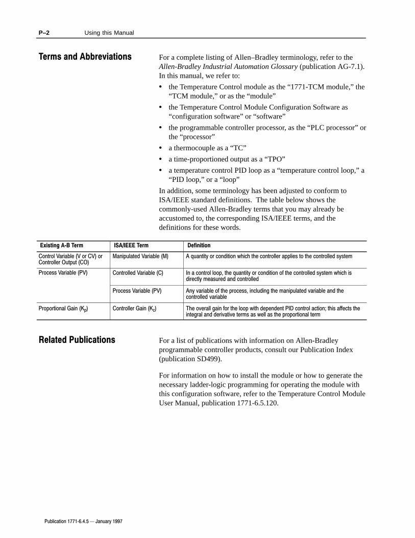
In addition, some terminology has been adjusted to conform toISA/IEEE standard definitions. The table below shows thecommonly-used Allen-Bradley terms that you may already beaccustomed to, the corresponding ISA/IEEE terms, and thedefinitions for these words.
Existing A�B Term ISA/IEEE Term Definition
Control Variable (V or CV) orController Output (CO)
Manipulated Variable (M) A quantity or condition which the controller applies to the controlled system
Process Variable (PV) Controlled Variable (C) In a control loop, the quantity or condition of the controlled system which isdirectly measured and controlled
Process Variable (PV) Any variable of the process, including the manipulated variable and thecontrolled variable
Proportional Gain (Kp) Controller Gain (Kc) The overall gain for the loop with dependent PID control action; this affects theintegral and derivative terms as well as the proportional term
For a list of publications with information on Allen-Bradleyprogrammable controller products, consult our Publication Index(publication SD499).
For information on how to install the module or how to generate thenecessary ladder-logic programming for operating the module withthis configuration software, refer to the Temperature Control ModuleUser Manual, publication 1771-6.5.120.
Terms and Abbreviations
Related Publications

Chapter 1
Publication 1771�6.4.5 - January 1997
Interfacing with theTemperature Control Module
This chapter describes how to interface the Temperature Controlmodule through the PLC processor to the configuration software.This includes:
• how the Temperature Control module configuration softwareinteracts with the PLC processor and the Temperature Controlmodule
• sample ladder logic (utility ladder logic provided)
• using the sample ladder logic program
• how the Temperature Control module communicates with thePLC processor
• how the Temperature Control software interfaces with PLCprocessors
• block-transfer programming
• data-table interface area
• communication control bits
The Temperature Control module configuration software provideseasy-to-use screens to help you configure, tune, and operatetemperature control modules. The configuration software does notcommunicate or transfer data directly with the module. Instead, thesoftware reads data from and writes data into an area of the PLC’sdata table, called the data table block. If you have multiple modules,each must have a separate data table block.
The utility ladder logic running on the PLC processor then transfersthis data to or from the module using block transfer instructions.You can select the area of the data table to be used by the software,but the arrangement of the data within the data table block is fixedby this software.
Utility ladder logic is provided with the configuration software. Werecommend that you use this utility ladder logic, since it contains allthe necessary block transfers and control instructions needed to usethe configuration software with the Temperature Control module,and has been tested to operate correctly with both the module and thesoftware.
How the TemperatureControl ModuleConfiguration SoftwareInteracts with the PLCProcessor and theTemperature ControlModule
Sample Ladder Logic

1–2 Interfacing with the Temperature Control Module
Publication 1771�6.4.5 - January 1997
The sample ladder logic can be combined with the other logic youneed for your application. If you prefer to write your own ladderlogic, it must duplicate the arrangement of data within the block andthe operation of the control bits that the sample logic uses in orderfor the configuration software to operate correctly.
During installation of the configuration software, you will have theoption of copying the sample ladder logic to your computer. Fromthere, you can restore the program to your processor using your PLCprogramming software. You then edit the subroutine in the sampleladder logic so that the block transfer instructions address the correctrack, group, and slot for your module. You also edit the subroutineto use your desired data table block address.
If you have multiple modules, you make a copy of the subroutine foreach module, and then edit the copies as described above. Refer toAppendix C of the Temperature Control Module User Manual(publication 1771-6.5.120) for detailed instructions on editing thesample ladder logic.
The Temperature Control module communicates with the PLCprocessor by both block-transfer and single-transfer. The ladderlogic must include block-transfer write instructions to send thefollowing data blocks to the module:
• a configuration block for each PID loop (8 max)
• gains block
• auto-tune block
• dynamic block
• calibration block (not required for normal operation)
The ladder logic must include block-transfer read instructions to getthe following data blocks from the module:
• system status
• gains block
• auto-tune block
• calibration block (not required for normal operation)
Unless the 1771-TCM module is located in a remote I/O chassis, youcan provide high-speed processing of time-proportioned output(TPO) signals by including instructions in the ladder logic fordealing with an input image byte single-transferred from the module.This byte contains the control-variable output of each loop as theduty cycle of a bit that is cycled at a regular period. Each bitrepresents one of the 8 PID loops.
Using the Sample LadderLogic Program
How the TemperatureControl ModuleCommunicates with PLCProcessors

1–3Interfacing with the Temperature Control Module
Publication 1771�6.4.5 - January 1997
The following graphic illustrates how the individual data blocks aresent to and returned from the TCM module.
Configuration Block for Loop 226 words
Configuration Block for Loop 126 words
Configuration Block for Loop 326 words
Configuration Block for Loop 426 words
Configuration Block for Loop 526 words
Configuration Block for Loop 626 words
Configuration Block for Loop 726 words
Configuration Block for Loop 826 words
Gains Block57 words
System Status Block64 words
Calibration Write Block20 words
Auto�Tune Block57 words
1771�TCM ModulePLC Data Table
Input Byte
Block�Transfer
Block�Transfer
Block�Transfer
Block�Transfer
Block�Transfer
Block�Transfer
Block�Transfer
Block�Transfer
Block�Transfer
Block�Transfer
Block�Transfer
Block�Transfer
Calibration Read Block14 words
Block�Transfer
Output Byte
Dynamic Block34 words
Block�Transfer
Single�Transfer
Single�Transfer
The computer with the Temperature Control software communicateswith the PLC processor across a local DH+ link or a DF1 serial link.
Important: For configuring temperature control loops, you can nothave the computer on one DH+ link and have the PLCprocessor on another (remote) DH+ link even if they arein the same DH+ network.
As shown in the following graphic, after entering configurationselections at the computer, you can download them to disk filesand/or the PLC processor’s data-table interface area for use by themodule. Later, you can upload configuration selections from eitherthe disk files or the PLC processor’s data-table interface area formaking changes.
How the TemperatureControl SoftwareInterfaces with PLCProcessors

1–4 Interfacing with the Temperature Control Module
Publication 1771�6.4.5 - January 1997
Download
Computer with Temperature Control Software
Data�Table Interface Area
PLC Data Table
RAM
Disk Files
Upload
For information on block-transfer programming, refer to yourTemperature Control Module User Manual (publication1771-6.5.120)
To use the Temperature Control configuration software, the read andwrite blocks, along with a control word, must be organized into a614-word data-table interface area in an integer file with the wordoffsets shown below. The utility ladder logic provides this.
Word Offset Description
0 Communication control word (initiates block�transfer of configurationauto�tune, or gains values when you set a specific bit)
1 Used by the example ladder logic as: BT identity bits
2 Used by the example ladder logic as: BT check mask
3 Used by the example ladder logic as: Cycle sequence number
4 Used by the example ladder logic as: Loop offset value
5 Used by the example ladder logic as: Data�table file offset
6 Not used by the example ladder logic
7 Not used by the example ladder logic
8 Not used by the example ladder logic
9 Used by the example ladder logic as: TPO bits single�transferred
10 - 39 Loop�1 configuration block (26 words)
40 - 69 Loop�2 configuration block (26 words)
70 - 99 Loop�3 configuration block (26 words)
100 - 129 Loop�4 configuration block (26 words)
130 - 159 Loop�5 configuration block (26 words)
160 - 189 Loop�6 configuration block (26 words)
190 - 219 Loop�7 configuration block (26 words)
220 - 249 Loop�8 configuration block (26 words)
250 - 309 Gains block (57 words)
310 - 349 Dynamic block (34 words)
350 - 419 Status block (64 words)
420 - 479 Auto�tune block (system ID data) (57 words)
480 - 549 Scratch�pad area addressed by the block�transfer write instruction (64 words)
550 - 613 Scratch�pad area addressed by the block�transfer read instruction (64 words)
Data�Table Interface Area

1–5Interfacing with the Temperature Control Module
Publication 1771�6.4.5 - January 1997
To establish a TCM project file, you must enter the starting addressof this interface area for each Temperature Control module. (SeeChapter 4 for more information.) The example ladder logic inAppendix C of the Temperature Control Module User Manual(publication 1771-6.5.120) uses N7:0 as the starting address for thisinterface area. To keep things simple, we recommend using word 0of a file as the starting address. However, as long as you provide theindicated word offsets, the interface area can start with any word inan integer file. If you install multiple Temperature Control modulesin your PLC system, you will need to assign a separate integer filefor each of them so that only one uses file N7. You will have tomake the corresponding address changes for each additional module.
Note that no areas are designated for calibration read or write blocks.Calibration is an off-line function that the Temperature Controlsoftware does not handle.
For details on how the example ladder logic program uses words 1through 5 and 9, refer to appendix C of the Temperature ControlModule User Manual (publication 1771-6.5.120). Your ladder logicprogram does not have to use words 1 through 9 in the same way asin the example ladder logic program. However, you must use words0 and 10 through 614 exactly as indicated.

1–6 Interfacing with the Temperature Control Module
Publication 1771�6.4.5 - January 1997
The configuration software uses word 0 to control thecommunications between the PLC processor and the module. Bits 0through 11 of word 0 of the data-table interface area arecommunication control bits. Based on your input to the TemperatureControl software, bits 0 through 11 will be used to initiate acorresponding block-transfer. Your ladder logic program mustrespond to this input by generating the required block-transfer. Bits14 and 15 are used internal to the example program.
WordOffset Bit Description
0 0 Loop�1 configuration block write to TCM required
1 Loop�2 configuration block write to TCM required
2 Loop�3 configuration block write to TCM required
3 Loop�4 configuration block write to TCM required
4 Loop�5 configuration block write to TCM required
5 Loop�6 configuration block write to TCM required
6 Loop�7 configuration block write to TCM required
7 Loop�8 configuration block write to TCM required
8 Auto�tune (system ID data) block write to TCM required
9 Auto�tune (system ID data) block read from TCM required
10 Gains block write to TCM required
11 Gains block read from TCM required
12 not used
13 not used
14 Used by the example ladder logic as: A manual download requested but no block�transfer in progress
15 Used by the example ladder logic as: Block�transfer to/from TCM in progress
0123456789101112131415
Loop
1
Loop
2
Loop
3
Loop
4
Loop
5
Loop
6
Loop
7
Loop
8
Write configuration block
Write gains block
Read gains block
Write auto�tune block
Read auto�tune block
Word N7:0
Initiate a block�transfer withone of these 12communication control bits
Do not control these 2bits with your ladderlogic outside of thisexample program
To learn how to install the Temperature Control configurationsoftware, read chapter 2
Communication ControlBits
What to do next

Chapter 2
Publication 1771�6.4.5 - January 1997
Installing the Software
This chapter shows you how to install the TemperatureControlconfiguration software for the 1771-TCM module. This includes:
• requirements for your computer
• preparation for installing the software
• installation procedure
• starting the software
• using online help
To use the TemperatureControl configuration software, your systemmust meet these requirements:
Hardware
• computer with an 80386 or greater microprocessor (80486 or Pentium recommended)
• at least 12 Mbytes of RAM
• hard drive with adequate free disk space (12 Mbytes or greater)
• 1.44 Mbyte floppy disk drive (for installing the software)
• VGA or higher-resolution adapter/monitor with small fonts.
We support 640x480, 800x600, 1024x786 modes. Werecommend a Super VGA resolution adapter/monitor.
• mouse
• DH+ port (on KT- or KL-type module) or standard serial port
Connection
• If you connect to the PLC processor through a DH+ port, thecomputer and the PLC processor must be on the same DH+ link
Software
• MS-DOS v5.0 or later
• Microsoft Windows v3.1 or v3.11, Windows for Workgroups3.11, or Windows 95
If you are using Windows 3.1 or 3.11, we recommend apermanent swap file of at least 10 Mbytes.
• TemperatureControl Configuration software
• INTERCHANGE
• Win32s if you are using Windows 3.1, 3.11, or Windows forWorkgroups 3.11
Requirements for YourComputer

2–2 Installing the Software
Publication 1771�6.4.5 - January 1997
The Temperature Control configuration software includes three setsof disks:
This set: Installs:
1 (3 disks) The configuration software itself
2 (2 disks) Win32s software (Windows 3.1 or 3.11 only)
3 (2 disks) INTERCHANGE software
Getting help while installing TemperatureControl software
• Press F1 to display installation help.
• Click on Cancel to abort the installation. You can run theinstallation setup a second time to complete an abortedinstallation (see page 2–2).
• If a serious error occurs during the installation, view the text fileINSTALL.LOG in your root directory. This file may help youfigure out what the problem is.
Convention
These instructions assume the 3½-inch disk is to be inserted intodrive a: of your computer. If drive a: is not used, replace the a: inthese instructions with the appropriate drive designation.
To install the TemperatureControl configuration software, followthese steps:
1. In the Windows Program Manager, from the File pull-down menu,select Run.
The Run dialog box appears.
Preparation for Installingthe Software
�
STOP
Installation Procedure

2–3Installing the Software
Publication 1771�6.4.5 - January 1997
2. Insert disk 1 of the Configuration Software into drive a: .
3. On the command line, type: a:\setup
4. Click on OK.
The software initialization screen appears, as well as a completionpercentage graph that indicates initialization status. Onceinitialization is complete, the Welcome screen appears.
5. Click on the Next button to continue with the installation.
A prompt appears, asking you if you wish to read the readme file.
Viewing the Readme file
Any last-minute changes or additions to these instructions aredescribed in a Readme file. If this file is present, a prompt appears:
We recommend that you select Yes. If you do, the installationresumes after you have viewed the Readme file. You can also viewthe file later by selecting its icon from the Allen-Bradley programgroup. If you do choose No, the installation continues immediately.
You are prompted to enter disk 2.
�

2–4 Installing the Software
Publication 1771�6.4.5 - January 1997
6. Insert disk 2 of the Configuration Software into drive a: andclick on OK.
The Choose Destination Location screen appears.
7. Either enter a new destination where you would like the TCMsoftware to be installed, or click on the Next button to accept thedefault directory.
If the directory does not already exist, you are prompted to decidewhether you want to create it. Choose Yes if you want the systemto create the directory.
The software installation continues and the percentage graphdisplays installation status.
You are prompted to enter disk 3.
8. Insert disk 3 into drive a: and click on OK.
The installation continues.
You are prompted to decide whether you want to install the ladderlogic utility programs. If you choose Yes, the Select Componentsscreen appears.

2–5Installing the Software
Publication 1771�6.4.5 - January 1997
9. Click on the Next button.
The Choose Destination Location screen appears.
10.Either enter a new destination where you would like the ladderlogic files to be installed, or click on the Next button to accept thedefault directory.
If the directory does not already exist, you are prompted to decidewhether you want to create it. Choose Yes if you want the systemto create the directory. The system then installs the files.
If you are using Windows 3.1 or 3.11, you are prompted to enterdisk 1 of the WIN32s files. If you are using Windows 95,proceed with step 13.
11.Insert disk 1 of the WIN32s files into drive a: and click on OK.
The installation continues.
Installing the Win32s files
If Win32s files already exist, the system compares the versionnumber of the existing copy to that of the new copy:
• If the existing copy is older, the prompt will indicate that thesoftware may not work properly with the old version, and askwhether to overwrite or leave the existing copy
• If the existing copy is the same or newer, you will still beprompted to either overwrite or leave the existing copy
You are prompted to enter disk 2 of the WIN32s files
12.Insert disk 2 of the WIN32s files into drive a: and click on OK.
As the system copies the Win32s files, it displays acompletion-percentage graph.
Once these files are installed, you are prompted to enter disk 1 ofthe INTERCHANGE software.
�

2–6 Installing the Software
Publication 1771�6.4.5 - January 1997
13.Insert disk 1 of the INTERCHANGE software into drive a: andclick on OK.
Existing INTERCHANGE software
If the current version of INTERCHANGE software already exists onthe computer, you are asked whether to reinstall the software.
As the system copies the INTERCHANGE files from disk 1, itdisplays a completion percentage graph.
When the system has copied the files from disk 1, you areprompted to insert disk 2:
14.Insert disk 3 of the INTERCHANGE software into drive a: andclick on OK.
Once the system has copied the remainder of theINTERCHANGE files, a prompt appears, giving you choicesabout modifying your AUTOEXEC.BAT file.
�

2–7Installing the Software
Publication 1771�6.4.5 - January 1997
15.In this dialog box:
If you select: Then:
Modify AUTOEXEC.BAT after creating a backup
copy.
(Note: This is the recommended choice.)
• the system asks if you want to modify your AUTOEXEC.BAT file so that itautomatically loads INTERCHANGE software. If you select No at thatprompt, you must manually start INTERCHANGE software *
• the system makes a backup copy of your AUTOEXEC.BAT file andmodifies the original
Make a backup copy of AUTOEXEC.BAT and
make changes to the copy.
• the system asks if you want to modify your AUTOEXEC.BAT file so that itautomatically loads INTERCHANGE software. If you select No at thatprompt, you must manually start INTERCHANGE software *
• the system will modify a copy of your AUTOEXEC.BAT file. You mustthen examine the copy and make the appropriate changes to your actualAUTOEXEC.BAT file. The software will not operate properly until youedit your actual AUTOEXEC.BAT file
Do not make any changes to AUTOEXEC.BAT. no changes will be made to your AUTOEXEC.BAT file. * The software will
not operate properly until you edit the AUTOEXEC.BAT file. Detailed
instructions on editing this file are in the INTERCHANGE software user
manual (publication 5000�6.6.6).
* If you select in either of these three cases to not make any changes to the AUTOEXEC.BAT file, you must first start
INTERCHANGE software before you start Windows.
You are prompted to decide whEther you want theAUTOEXEC.BAT file modified so that it will automatically loadwhen you start your computer. You are also reminded to rebootyour system to make the changes take effect.
The system then prompts you with this dialog box:
Note: If INTERCHANGE is already installed and configured,you will not see this dialog box.

2–8 Installing the Software
Publication 1771�6.4.5 - January 1997
16.In this dialog box:
If you select: Then:
Yes
the system alerts you that installation will resume after you have completed device configuration.
Click on OK. You see:
Refer to the Device Configuration Utility User Manual, publication 5850�6.5.7, for detailed instructions on
using this utility.
No
you see:
Click on OK.

2–9Installing the Software
Publication 1771�6.4.5 - January 1997
After you’ve rebooted your computer, follow these steps to start thesoftware:
1. In the Allen-Bradley program group, select theTemperatureControl icon.
TemperatureControl icon
2. From the File pull-down menu, select Open.
As it loads the software, a welcome screen appears.
When the software is loaded, you see the Temperature ControlProject screen:
Starting the Software

2–10 Installing the Software
Publication 1771�6.4.5 - January 1997
To access the TemperatureControl software online help, from theHelp pull-down menu, you can select Contents:
You see the TemperatureControl online help Contents screen. Clickon any of the underlined text to view the help on that topic.
You can also press F1 from any screen to view help for that screen.
To learn how to use the online help screens, from the Help pull-downmenu, select How to Use Help. The How to Use Help screen appears.
To learn how to organize the Temperature Control project file, readChapter 3.
Using Online Help
What to do next

Chapter 3
Publication 1771�6.4.5 - January 1997
Organizing the Project File
This chapter shows you how to organize a temperature controlproject file. This includes:
• a definition of the temperature control project file
• creating a project file
• adding modules to the project file
• modifying an existing module
Before you can configure a temperature control module, you mustcreate a project file that includes the module and its loops. Eachproject file can hold information for one or more temperature controlmodules. Use a single project file for all modules used on a commonproject controlled by a PLC processor or multiple PLC processors onthe DH+ link. For example, if a molding machine uses 5 TCMmodules, use a single project file for all 5 modules.
For each temperature control module you add to the project file, youmust establish:
• a symbolic name for the module
• the address on the DH+ link of the PLC processor for the module
• the starting address of the contiguous data table area forinterfacing with the module
See chapter 1 for details of how this interface area must bearranged.
• the module location address (rack/group/slot)
To create a project file:
1. Start the software as described in chapter 2 to show thetemperature control modules directories.
The Temperature ControlProject File
Creating a Project File

3–2 Organizing the Project File
Publication 1771�6.4.5 - January 1997
If you previously created and saved any project files, thediretories where they were saved will be listed in the PreviousDirectories page. Click on a directory to display the project filesin that directory. Click on a file to display its description, ordouble click on a file to open the Module Manager screen for thatproject.
2. From the File pull-down menu, select New.
The New-Project dialog box appears.
3. Type the project/file name and then select OK. Use a short namethat describes the project; for example, Molding_Machine_1.Spaces are not allowed. However, underscores are allowed.
The Module Manager screen for the project appears.

3–3Organizing the Project File
Publication 1771�6.4.5 - January 1997
To add a module to the project file:
1. From the Module pull-down menu, select New.
The New Module dialog box appears.
2. In this dialog box, enter the following for the module.
In this field: Select on enter:
Name: A short descriptive name to help you identify the module.
PLC Node: The node number on the DH+ link of the PLC processor for
the module. If you are using a DF1 link to the PLC
processor, this value is ignored.
Port: The INTERCHANGE port the software should use to
communicate to the PLC processor. These ports are
defined when you run the INTERCHANGE configuration
utility. Most users configure only one port, and it will
appear by default. If you have more than one port
configured, click on the arrow to display the list.
DT Address: The starting address of the contiguous data table area for
interfacing with the module. (See chapter 1 on details of
how this interface area must be arranged.)
Rack No.: The I/O rack number for the module location address.
Group No.: The I/O group number within the I/O rack for the module
location address.
Slot No.: 0 (The I/O module slot number within the I/O group.)
The rack, group, and slot numbers are for screen displayreference only. It is up to your ladder logic to provideblock-transfer to and from the correct location address for themodule.
Adding Modules to theProject File

3–4 Organizing the Project File
Publication 1771�6.4.5 - January 1997
3. Select OK.
The module list for the project appears, with the module added.The new module will have 8 default loop names.
If you want to edit the project description that shows on the firstscreen, from the Project pull-down menu, you can select Description.
The project description is also printed when you print a project.
To change the Name, PLC Node, Port, Data Table Address, Rack,Group, or Slot of an existing module:
1. At the Module Manager screen, select the module you wish tomodify.
2. From the Module menu, select Modify.
The Modify Module dialog box appears, with the current settingsshown.
3. Make the desired changes and click on OK.
To learn how to configure the temperature control module, readchapter 4.
�
Modifying an ExistingModule
What to do next

Chapter 4
Publication 1771�6.4.5 - January 1997
Configuring the Modules
This chapter shows you how to configure the 1771-TCM module.This includes:
• configuration selections
• uploading and downloading information
• accessing the Module Configuration screen
• downloading configuration values
• uploading configuration values
• module description
• copying configuration values from one module to another
• copying configuration values from one module into a new module
• moving a module from one project to another
On the module configuration screen, you are given severalconfiguration selections to establish. However, your selections donot control the PLC data table values in real time. These selectionsdo not take effect until you download the selection to the PLC datatable interface area.
The configuration software can write (download) configurationinformation directly to the PLC data table in online mode, or it canwrite it to a disk file in off-line mode. Similarly, the configurationsoftware can also read configuration information from the PLCprocessor or from a file.
In order to use online mode, you must have a DH+ or serialconnection with the PLC processor, and INTERCHANGE must beproperly configured and running. When you write configuration datato a file, it is stored as part of the project file. It is a good idea toalways download to both the file and to the PLC processor. Thisway, the file retains a copy of all of the configuration data; you canthen use this copy to restore the configuration data to the PLCprocessor if that information is ever lost or damaged.
Downloading to the file alone lets you perform configurationfunctions while you are disconnected from the PLC processor. Onceyou are attached to the PLC processor, you can transfer informationfrom the file to the processor by first uploading from the file, andthen downloading to the processor. When you are simply testingchanges, you may want to download only to the PLC processor sothat the file retains your un-altered settings. Once you are satisfiedwith those changes, you can download to the file to save them.
Configuration Selections
Uploading andDownloading Information

4–2 Configuring the Modules
Publication 1771�6.4.5 - January 1997
When you first open any of the configuration screens, the softwareattempts to perform an upload from the PLC processor so that thescreen displays the current values the module is using. If thesoftware cannot upload from the processor (e.g. if the connection tothe processor has been broken), then the software performs anupload from the file. Now the data source (the PLC or file) is shownin the left-hand side of the status bar at the bottom of eachconfiguration screen. The right-hand side of the status bar displaysthe destination when you perform a download.
While the software is uploading data from the PLC processor or file,it checks each value to make sure it is within the allowable range ofvalues for the particular parameter. If the value is outside theallowable limits, it will be reset to a default value for that parameter.When this occurs, a warning message appears on the screen. Undernormal conditions, this should not occur, but it may happen whenyou are uploading data from a module that has never beenconfigured, since the data table will contain random data.
Normally, when you perform an upload or download, you aretransferring information for a single loop only. Some screens allowyou to upload or download information for all eight loops in amodule at the same time. This is useful, for example, to downloadan entire module from the PLC processor and save it to a file withouthaving to perform eight separate uploads and downloads. However,since the command can alter data you may not intend to alter, you areprompted for confirmation when you attempt to download an entiremodule at once.
Screens that are intended to monitor the module as it operates, suchas the Loop Monitor screen or the Module Monitor screen, onlydisplay information from the PLC processor. If the connection to theprocessor is not available when you attempt to open a monitorscreen, you will receive an error message and the screen will close.
To configure a module, access the module configuration screen:
1. At the Module Manager screen, select the module.
2. From the Module menu, select Configure.
Accessing the Module menu
Clicking on the right mouse button while the pointer is over themodule list on the Module Manager screen will display a popupversion of the Module menu. (Clicking on the right mouse buttonbrings up context-sensitive menus throughout the software.)
Accessing the ModuleConfiguration Screen
�

4–3Configuring the Modules
Publication 1771�6.4.5 - January 1997
The Module Configuration screen for the module you selectedappears.
3. Select your desired temperature units (Celsius or Fahrenheit).
All temperature values will be displayed in the selected units, andyou should enter all temperature values in these units.
4. Enable or disable the cold-junction alarms.
When cold-junction alarms are enabled, the cold-junction alarmbit in the data table will be set any time the cold-junctiontemperature exceeds seventy degrees Celsius, or falls below zerodegrees Celsius.
5. Select the desired C Display Mode (Normal or Integer).
When you select Integer, the module will set the least significantdigit (tenths of degrees) of the C Temperature output to 0. (Youcan view the temperature on the Loop Monitor and ModuleMonitor screens.)
For example:
If the Actual value is: Then the Normal value is: Or the Integer value is:
123.6 123.6 123.0
256.1 256.1 256.0
�127.3 �127.3 �127.0
This setting applies to all the loops in the module.
Note: This feature is only supported in Module FirmwareVersion 3.3. and later.
The Module Configuration screen displays the revision number ofthe module’s firmware. This lets you determine the revision levelof your module without removing the module from service.
Note: The module firmware revision will only be valid whendata has been uploaded from the PLC processor.

4–4 Configuring the Modules
Publication 1771�6.4.5 - January 1997
Once you have made your desired selections on the ModuleConfiguration screen, you must download these parameter values.To do so:
1. From the Module menu, select Download.
Accessing the Download function
You may also access the Download function by pressing CTRL + D.
The Download dialog box appears.
If you choose: Then:
Download to PLC the configuration values are downloaded to the PLC
data table block. From there, the ladder logic
block�transfers them to the TCM module.
Save to the disk file the configuration values are downloaded to the disk
file, from where they can be uploaded as needed.
2. Select either or both and click on OK.
The values are then downloaded, the dialog box closes, and theright-hand section of the status bar at the bottom of the window isupdated to show the values were downloaded.
Some screens have both Loop and Module menus. On thesescreens, when you select upload or download from the Loopmenu, the only data transferred is that for the loop on which thescreen was opened. When you select upload or download fromthe Module menu, the data for all eight loops of the module aretransferred. This is useful, for example, to upload an entiremodule from the PLC processor and then save it to the disk file,without having to go to eight separate screens and perform eightseparate uploads and downloads. Because this command, if usedimproperly, can alter data you did not intend to alter, you areprompted for confirmation when you attempt to perform amodule download.
DownloadingConfiguration Values
�

4–5Configuring the Modules
Publication 1771�6.4.5 - January 1997
Although an automatic upload is performed when a screen firstopens, you may also perform a manual upload at any time. This isuseful, for example, when you want to transfer data stored in the diskfile to the PLC processor by first uploading from the file and thendownloading to the processor.
To upload configuration values:
1. From the Module menu, select Upload.
Accessing the Upload function
You may also access the Upload function by pressing CTRL + U.
The Upload dialog box appears.
2. Select your desired upload source and click on OK.
The values are then uploaded, the dialog box closes, and theleft-hand section of the status bar at the bottom of the window isupdated to show the values were uploaded.
Some screens have both Loop and Module menus. On thesescreens, when you select upload or download from the Loopmenu, the only data transferred is that for the loop on which thescreen was opened. When you select upload or download fromthe Module menu, the data for all eight loops of the module aretransferred. This is useful, for example, to upload an entiremodule from the PLC processor and then save it to the disk file,without having to go to eight separate screens and perform eightseparate uploads and downloads. Because this command, if usedimproperly, can alter data you did not intend to alter, you areprompted for confirmation when you attempt to perform amodule upload.
Uploading ConfigurationValues
�

4–6 Configuring the Modules
Publication 1771�6.4.5 - January 1997
You can enter descriptive information for each module. This can beany information you wish to associate with the module, such asphysical location, product being manufactured, etc. You can viewthis information at any time; it is included in printed reports, as well.
To enter or view the module description:
1. At the Module Manager screen, select a module.
2. From the Module menu, select Description...
The Module Description screen is displayed for the module youselected.
3. Enter or edit the description for the module and click on OK.
If you have several modules that are similar or identical, you canconfigure one module and then use that module to configure othersimilar modules.
Note: Before you do this, you may wish to perform the loopconfiguration described in Chapter 5 of this manual, and the tuningconfiguration described in Chapter 6. That way, those settings willbe copied to the other modules as well.
To copy configuration data from one module to another:
1. At the Module Manager screen, select the first (source) module.
2. From the Edit menu, select Copy.
3. Select the second (destination) module.
The destination module can be in the same project or a differentproject.
Module Description
Copying ConfigurationValues From One Moduleto Another

4–7Configuring the Modules
Publication 1771�6.4.5 - January 1997
4. From the Edit menu, select Paste into selection.
5. Go to each configuration screen for the destination module, viewthe pasted data, make any required changes, and then downloadto the PLC processor, to a file, or to both to save the pasted data.
To save all configuration parameters, you must do this from theModule Configuration, Loop Configuration, TuningConfiguration, and Tuning Results screens, since each of thesescreens downloads (or uploads) only the parameters shown on theparticular screen.
From the Loop Configuration, Tuning Configuration, and TuningResults screens, you can simultaneously download all eight loopsat once by using the Module Download command.
You can also use one module to configure another new module.
Note: Before you do this, you may wish to perform the loopconfiguration described in Chapter 5 of this manual, and the tuningconfiguration described in Chapter 6, so that those settings arecopied to the new module as well.
1. At the Module Manager screen, select the first (source) module.
2. From the Edit menu, select Copy.
3. From the Edit menu, select Paste into new.
The New Module dialog box appears.
4. Fill in the information in the dialog box and click on OK.
The new module will be added to the module list.
5. Go to each configuration screen for the destination module, viewthe pasted data, make any required changes, and then downloadto the PLC processor, to a file, or to both to save the pasted data.
To save all configuration parameters, you must do this from theModule Configuration, Loop Configuration, TuningConfiguration, and Tuning Results screens, since each of thesescreens downloads (or uploads) only the parameters shown on theparticular screen.
From the Loop Configuration, Tuning Configuration, and TuningResults screens, you can simultaneously download all eight loopsat once by using the Module Download command.
Copying ConfigurationValues From One ModuleInto a New Module

4–8 Configuring the Modules
Publication 1771�6.4.5 - January 1997
To move a module from one project to another:
1. At the Module Manager screen, select the module you wish tomove.
2. From the Edit menu, select Cut.
3. Close the Module Manager screen.
4. From the Project Manager screen, open the destination project (orcreate a new project).
5. From the Edit menu, select Paste into new.
The New Module dialog box appears.
6. Fill in the information in the dialog box and click on OK.
The new module will be added to the module list.
7. Go to each configuration screen for the destination module, viewthe pasted data, make any required changes, and then downloadto the PLC processor, to a file, or to both to save the pasted data.
To save all configuration parameters, you must do this from theModule Configuration, Loop Configuration, TuningConfiguration, and Tuning Results screens, since each of thesescreens downloads (or uploads) only the parameters shown on theparticular screen.
From the Loop Configuration, Tuning Configuration, and TuningResults screens, you can simultaneously download all eight loopsat once by using the Module Download command.
To learn how to configure the loops of the temperature controlmodule, read chapter 5.
Moving a Module FromOne Project to Another
What to do next

Chapter 5
Publication 1771�6.4.5 - January 1997
Configuring the Loops
This chapter shows you how to configure the PID loops of the1771-TCM module. This includes:
• changing default loop names
• configuration selections
• thermocouple break detection
• thermal integrity detection
• alarm dead band
• fine-tuning the loops
• bringing up the Loop Configuration screen
• entering configuration values
• downloading configuration values
• uploading configuration values
• using one loop to configure another
To change default loop names:
1. At the Module List screen, select the module for which you wantto generate the loop list.
As you select a module on the Project screen, the loop list for thatspecific module is displayed.
2. Select a loop.
3. From the Loop pull-down menu, select Name.
The Loop-Name dialog box appears.
4. Enter a symbolic name for the loop.
5. Select OK.
You see the loop list for the module.
Changing Default LoopNames

5–2 Configuring the Loops
Publication 1771�6.4.5 - January 1997
6. Repeat from step 2 until you have made all desired changes to theloop list.
On the Configuration screen, you are given several configurationselections to establish. However, your selections do not control thePLC data table values in real time. These selections do not takeeffect until you download the selections to the PLC data-tableinterface area.
If a loop input circuit becomes open (a wire breaks or vibrates loose)the loop can not measure the temperature. In automatic mode, thelack of temperature feedback would make it impossible to control thetemperature. To guard against such a lack of temperature control,the module provides open-circuit detection.
You select a mode to which the loop is to switch when an open inputcircuit is detected in automatic mode. The selections are:
• disable the PID loop by forcing the manipulated variable (M)value to zero
• set the output to the open-circuit forced M value
• set the loop to the manual mode (force M to manual output value)
Configuration Selections
Open�Circuit Detection

5–3Configuring the Loops
Publication 1771�6.4.5 - January 1997
Under control type, you select between barrel and non-barrel control.Barrel control can be used for either heat-only or heat/coolapplications. Non-barrel control can be used for either heat-only,cool-only, or heat/cool applications.
Barrel control is for multiple-zone applications in which there isthermal conduction between the zones. Injection molding andextruding are good examples of this because there are multiple heaterbands (zones) mounted on one thermal conductor (the metal barrel).The barrel conducts heat between the different zones. If you selectbarrel control, you must also select between inner and outer zone. Ifyou select barrel control, the non-barrel auto-tune disturbance sizedoes not apply. A barrel loop is auto-tuned as the temperature risesfrom ambient to a fixed set point during startup.
Non-barrel control is for independent loops with no thermalconduction between the zones. If you select non-barrel control, theinner/outer zone selection does not apply. If you select non-barrelcontrol, the loop is auto-tuned as it reacts to the set point disturbanceyou enter.
Switch to Barrel Control?
For some applications, even though the loops are independent withno thermal conductivity between zones, barrel control may providebetter performance than non-barrel control. If a loop has any ofthese characteristics, you may want to try switching it to barrelcontrol.
• The time constant is greater than 100.0 seconds. (You can readthe time constant for each loop in the auto-tune block.)
• The loop has a problem overshooting the set point.
• The loop output is saturating (the M at 100%) for a significantduration.
If you switch a loop to barrel control for one of these reasons, selectit to be an outer zone.
!ATTENTION: If you switch a loop betweennon-barrel control and barrel control, you mustauto-tune the loop again before operating it. If you failto auto-tune the loop after making such a switch, theauto-tuning values will be wrong for the applicationand the gains will be greatly distorted.
Barrel/Non�Barrel Control

5–4 Configuring the Loops
Publication 1771�6.4.5 - January 1997
If you make the selection for barrel temperature control, you alsohave a selection for whether it is an inner zone or an outer zone. Anouter zone is a zone at either end of the barrel. An inner zone is anyzone other than at the very end of the barrel (between two otherzones). The PID gain calculation algorithm for an inner zone isslightly different from that for an outer zone to account for an innerzone being more affected by adjacent zones. The inner zones aretreated as more of an integrating process than are outer zones.
ÍÍ
ÍÍ
Í
Í
ÍÍ
ÍÍ
ÍÍ
ÍÍ
Í
Í
Í
Í
ÍÍ
ÍÍ
HnH1 H2 H3
NozzleZone 1 Zone 2 Zone 3
Ts Tn T1 T2 T3 Tf
T = temperature measurement point (thermocouple)H = heater band (element)
Typical plastic injection barrel with multiple temperaturezones
Ram(Screw)
OuterZone
OuterZone
InnerZone
InnerZone
The loss of thermal integrity is detected when the loop M output is at100% while the temperature rate of change measured by the moduleis below the minimum expected rate. Detecting the loss of thermalintegrity requires an assumption of a minimum rate of change in thetemperature input value (C) when the M output is at 100%. Anexample of a loss of thermal integrity could be because the contactorfor a heating band fails open; or the sensor is not in proper positionto measure the true temperature.
The values you enter for period and temperature change establish aminimum rate of change (°/min) in the temperature input value thatyou will allow when the M output is at 100%. The temperaturechange value you enter divided by the period value you enter is thethermal integrity rate. You select a mode for switching the M outputto a forced value when the rate of change of the temperature does notreach the minimum for thermal integrity. The selections are:
• disable the PID loop by forcing the M value to zero
• set the output to the thermal runaway forced M value
• set the output to the manual-mode M value by setting the loopinto manual mode
If a thermal integrity loss is detected, you must disable the affectedloop and then re-enable it to clear the condition. You can do thisfrom the Change Settings screen.
Inner/Outer Zone
Thermal Integrity LossDetection

5–5Configuring the Loops
Publication 1771�6.4.5 - January 1997
In the Loop Configuration screen, you select values for the followingtemperature-level alarms:
• low temperature alarm
• high temperature alarm
• low deviation alarm (deviation from the set point)
• high deviation alarm (deviation from the set point)
Low TemperatureAlarm Value
Low DeviationAlarm Value
Set Point
High TemperatureAlarm Value
High DeviationAlarm Value
0°Time
Tem
pera
ture
Alarms

5–6 Configuring the Loops
Publication 1771�6.4.5 - January 1997
Once the temperature alarm bits are on, they are kept on until thetemperature drops below the high alarm by the alarm dead-bandvalue or rise above the low alarm by this value. You specify thetemperature alarm dead band. This dead band provides a hysteresiseffect. The dead-band value applies to the high and low temperatureand deviation alarm values.
• Low Alarm With Dead Band — When the temperature fallsbelow the user-defined low alarm value, the low alarm bit isturned on. When the temperature rises above the level of the lowalarm value but still below the level of the dead-band value, thelow alarm bit remains on. Only when the temperature rises abovethe dead-band level will the alarm bit be turned off.
• High Alarm With Dead Band — When the temperature risesabove the user-defined high alarm value, the high alarm bit isturned on. When the temperature falls below the level of the highalarm value but still above the level of the dead-band value, thehigh alarm bit remains on. Only when the temperature fallsbelow the dead-band level will the alarm bit be turned off.
High Alarm Level
Low Alarm Level
TimeTime alarm on
The temperature passes thruthe dead band before the alarmis turned on or off to providestability to alarm indicators
without dead band with dead band
alarm off
dead band
dead band
Tem
pera
ture
The ladder logic can send the TPO signal to a digital output moduleto generate the control variable output signal to a digital temperaturecontrol actuator.
X
Y
On
Off
Duty Cycle = X
Y
TPO Bit
X = On Time
Y = TPO Period
You set the period and minimum on time for each loop’s heat andcool TPO bits. You must set the TPO period to be less than thesystem lag time (i.e. deadtime plus the time constant; this time isavailable from the autotune results). If the TPO period is greaterthan the lag time, the auto-tuning will calculate large gain values,which will probably cause the temperature to overshoot the set point.
Alarm Dead Band
TPO Bit

5–7Configuring the Loops
Publication 1771�6.4.5 - January 1997
In general, a smaller TPO period provides smoother control unlessthe minimum on time is greater than 10% of the TPO period. If thethe minimum on time is greater than 10% of the TPO period, theTPO signal will not be able to provide any control of the temperatureuntil the temperature has moved away from the set point far enoughto require a 10% TPO signal.
A long minimum on time reduces wear on the heating or coolingcontactors by reducing the cycling when the duty cycle is low.However, a short minimum on time provides smoother control,especially if the TPO period is short.
To configure a loop, access the Loop Configuration screen asfollows:
1. At the Module Manager screen, select the module.
2. Select the loop to configure.
3. From the Loop pull-down menu, select Configure.
Displaying the popup Loop menu
To display a popup version of the Loop menu, click on the rightmouse button while the cursor is over the loop list.
The Loop Configuration screen for the loop you selected appears.
Accessing the LoopConfiguration Screen
�

5–8 Configuring the Loops
Publication 1771�6.4.5 - January 1997
Viewing configuration data
If you want to view the configuration data for a different loop, youcan select Next or Previous from the Loop menu to cycle through theloops. You can also press CTRL + N or CTRL + P.
Enter loop configuration values within the stated ranges. In eachcase where a decimal point is shown, if you want to enter a digit tothe right of the decimal point, you must type in the decimal point; thedecimal point is not inferred.
Listing acceptable values
When you position the mouse pointer over a field that requires anumeric entry (e.g. Run Set point), there will be a brief delay, afterwhich a small window appears that identifies the acceptable range ofvalues for that parameter. You can find additional information in theonline help.
The following table provides you with the appropriate values to enterfor each field.
�
Entering LoopConfiguration Values
�

5–9Configuring the Loops
Publication 1771�6.4.5 - January 1997
In this field: Enter this value:
Run Setpoint 0.0 thru 3276.7°Standby Setpoint 0.0 thru 3276.7°Manual Output Value -100.00 thru +100.00
SP Ramp Rate0.00 thru 99.99°/min If enabled, the rate at which the current set point is increased or decreased to
reach the selected set point.
SP Ramp Enable Toggles between enable and disable
Max. M Limit -100.00 thru +100.00% The maximum M percentage allowable.
Min. M Limit -100.00 thru +100.00% The minimum M percentage allowable.
Heat TPO Period 0 thru 100.00s The period in seconds at which the heat bit is cycled and the M is updated.
Heat Min. On Time
0 thru 100.00s The minimum time in seconds for which the heat bit is turned on during the TPO period.
If the calculated time is less than this minimum, the heat bit will not be turned on. This on time must be less
than the heat TPO period.
Cool TPO Period 0 thru 100.00s The period in seconds at which the cool bit is cycled and the M is updated.
Cool Min. On Time
0 thru 100.00s The minimum time in seconds for which the cool bit is turned on during the TPO period.
If the calculated time is less than this minimum, the cool bit will not be turned on. This on time must be less
than the cool TPO period.
High Temp Alarm-3276.8 thru 3276.7° A temperature value at the high end of the sensor limit, but still below the
maximum temperature value.
Low Temp Alarm-3276.8 thru 3276.7° A temperature value at the low end of the sensor limit, but still above the minimum
temperature value.
High Deviation Alarm-3276.8 thru 3276.7° A value that specifies the greatest deviation above the set point that the process
can tolerate.
Low Deviation Alarm-3276.8 thru 3276.7° A value that specifies the greatest deviation below the set point that the process
can tolerate.
Dead Band for Alarms
0.0 thru 10.0° Once the temperature alarm bits are on, they are kept on until the temperature drops
below the high alarm point by this value rises above the low alarm point by this value. The dead�band value
applies to all alarms.
C Alarm Rate-3276.8 thru 3276.7°/s If the rate of temperature (C) increase is greater than this value, the C rate alarm
is triggered. A value of 0.0 disables the C rate alarm.
Temperature Sensor Type mV, B, E, J, K, R, S, T
Temperature Sensor Filter
When enabled, the C input is passed through a first order step equivalent lag filter. The filter's time constant
is determined by the value entered in the TC field.
Note: This feature is only supported in Module Firmware Version 3.3 and later.
Temperature Sensor TC
This is the filter time constant for the C input filter, and can range from 0.0 to 9.9 seconds. A setting of 0.0
effectively disables the filter.
Note: This feature is only supported in Module Firmware Version 3.3 and later.
Open Circuit Action• Disable Loop (M=0)• M = On Break M value The forced M value on TC break.• M = Manual Output value
Open Circuit M Value -100.00 thru +100.00 The percentage value to force into the M output when a broken TC is detected.
TIL Configuration• Disable Loop (M=0)• M = On TIL M The forced M value on thermal integrity loss.• M = Manual Output value
TIL Forced M Value-100.00 thru +100.00 The percentage value to force into the M output when thermal integrity loss is
detected.
TIL Period 0 thru 100 minutes
TIL Temp. Change 0 thru 100°Auto / Manual Auto or Manual
Desired System Response
Slow, Medium, Fast, or Very Fast The system response desired as a result of auto�tuning. This
selection will be used together with system parameter measured during auto�tuning to generate the
auto�tuning gains.
Control Type Barrel or Non�Barrel
Zone Inner or Outer
Control Action E�=�SP-C or E�=�C-SP

5–10 Configuring the Loops
Publication 1771�6.4.5 - January 1997
Once you have entered the appropriate values at the Configurationscreen, you must download these parameter values. To do so:
1. From the Loop pull-down menu, select Download.
Accessing the Download function
You may also access the Download function by pressing CTRL + D.
The Download dialog box appears.
If you choose: Then:
Download to PLC the configuration values are downloaded to the PLC
data table block. From there, the ladder logic
block�transfers them to the TCM module.
Save to the disk file the configuration values are downloaded to the disk
file, from where they can be uploaded as needed.
2. Select either or both and click on OK.
To configure the loop, choose download to the PLC.
At this point the Download dialog box is removed from theConfiguration screen, and the module configuration is complete.
DownloadingConfiguration Values
�

5–11Configuring the Loops
Publication 1771�6.4.5 - January 1997
In the case that you are reconfiguring a loop or group of loops, youmay find it useful to first upload the old configuration values for thatmodule. Also, after downloading, you’ll want to verify that the PLCprocessor received the correct information. To do so, at the Loop
pull-down menu, select Upload.
1. From the Loop pull-down menu, select Upload.
Accessing the Upload function
You may also access the Upload function by pressing CTRL + U.
The Upload dialog box appears.
2. Select your desired upload source and click on OK.
Uploading ConfigurationValues
�

5–12 Configuring the Loops
Publication 1771�6.4.5 - January 1997
If you have several loops that are similar or identical, you canconfigure one loop and then use that loop to configure the othersimilar loops.
To copy configuration data from one loop to another:
1. At the Module Manager screen, select the loop that has thedesired configuration (i.e. the source loop).
2. From the Edit menu, select Copy.
The values from the source loop will be placed on the Windowsclipboard.
3. Select the second (i.e. destination) loop
The destination loop can be in the same module, a differentmodule, or a different project.
4. From the Edit menu, select Paste into selection.
5. Go to each configuration screen for the destination loop, view thepasted data, make any required changes, and then download to afile, to the PLC processor, or both to save the pasted data.
To save all configuration parameters, you must do this from theLoop Configuration screen, Tuning Configuration screen, and theTuning Results screen, since each of these screens downloads (oruploads) only those parameters shown on the screen.
Note: When you open a screen that has pasted data, theautomatic upload from the PLC processor or the file is inhibitedto prevent overwriting the pasted data, and the status panedisplays the message “Values pasted from clipboard.”
When you paste into a loop, the name of the destination loop remainsthe same, but all the configuration values are replaced with thosefrom the source loop. The values used from the source loop arethose that were last displayed on the configuration screens for thatloop. In other words, if you perform an upload from a file for thesource loop and then perform a copy command, the values that areplaced on the clipboard are those from the file, whereas if youperform an upload from the PLC processor prior to performing thecopy, the PLC values are placed on the clipboard.
Using One Loop toConfigure Another

5–13Configuring the Loops
Publication 1771�6.4.5 - January 1997
You can enter descriptive information for each loop. This caninclude any information you wish to associate with the loop, such asphysical location, product being manufactured, etc. You can viewthis information at any time; it is also included in the printed reports.
To enter or view the loop description:
1. At the Module Manager screen, select a loop.
2. From the Loop menu, select Description...
The Loop Description screen appears for the loop you selected.
3. Enter or edit the description for the loop and click on OK.
To learn how to tune the loops, read chapter 6.
Loop Description
What to do next

5–14 Configuring the Loops
Publication 1771�6.4.5 - January 1997
Notes:

Chapter 6
Publication 1771�6.4.5 - January 1997
Tuning the Loops
This chapter shows you how to tune a loop. This includes:
• configuring tuning
• auto-tuning the loops
• viewing auto-tuning results
• changing system response
• fine-tuning the loops
Before a PID loop can be run in automatic control mode, theproportional, integral, and derivative gains must be set.Traditionally, these gains have been set manually using a trial anderror process. This manual process can be very time-consuming, andoften results in less than optimal performance.
Although you can use the manual process to set the gains, the TCMmodule includes an advanced auto-tuning algorithm that is capableof automatically determining near optimum gain values. Werecommend that you use the auto-tuning process to determine initialgain values, which can then be adjusted manually, if necessary, tocorrect any slight remaining performance problems.
During auto-tuning, the TCM module controls the loop output andmonitors the change in the measured variable in order to measureseveral parameters that are characteristic of your process. Usingthese parameters, the TCM module then calculates proportional,integral, and derivative gains that will provide good automaticcontrol. This process can take from a few minutes to several hours,depending on the response time of your process.
Before you begin the auto-tuning process, we recommend that youperform several preparatory steps:
1. After configuring your module and loops, as described inChapters 4 and 5, operate your loops in Manual mode.
By operating the loop in Manual mode, you can verify that theinputs and outputs are connected properly, the temperaturesensors are correctly measuring your process temperature, and theloop output properly controls heating and/or cooling.
Introduction to LoopTuning
The Auto�Tuning�Process
Preparing to Auto�TuneLoops

6–2 Tuning the Loops
Publication 1771�6.4.5 - January 1997
2. Once you are satisfied that your loop is operating properly inManual mode, use the Manual Tuning screen to set theproportional gain to 1, leaving the integral and derivative gains at 0.
This configures the loop for straight proportional control.
3. Place the loop in Automatic mode.
With a proportional gain of 1, the loop output should be directlyproportional to the deviation between the measured variable andthe setpoint.
4. When you are satisfied the loop is operating properly in thismode, you can proceed with the auto-tuning process described inthe following sections.
Important: You must allow the equipment to cool downbefore you begin the autotune process or yourresults will be invalid.
There are several tuning parameters that you can configure to tailorthe auto-tuning process to suit particular applications:aggressiveness, disturbance size, and system response.
• Aggressiveness
The aggressiveness setting affects how the module controls theloop during start-up in barrel control mode. Start-up is the periodbetween the time the loop is placed in Automatic control at a lowinitial temperature, and the time it first nears the setpoint.
This setting can range from 0 to 100. A setting of 0 minimizesthe chance of overshoot during start-up, but increases the timeneeded to reach the setpoint. A setting of 100 minimizes start-uptime, but will result in the temperature overshooting the setpointduring start-up.
This setting does not affect the quality of the control once thestart-up period has passed. During an ideal start-up, thetemperature should rise steeply toward the setpoint. As thetemperature nears the setpoint, the rate of climb should graduallylevel off until the temperature reaches the setpoint. If thetemperature drops for a while after the initial climb before slowlyclimbing toward the setpoint, you should increase theaggressiveness.
• Disturbance Size (non-barrel loops only)
Disturbance size is the percentage of the step change made in theoutput during auto-tuning of non-barrel loops. The disturbancesize setting can range from 0.00 to 100.00. (Note: A setting of0.00 is equivalent to a setting of 100.00.)
Tuning Parameters

6–3Tuning the Loops
Publication 1771�6.4.5 - January 1997
Since non-barrel loops are tuned starting from the setpoint,instead of from a low temperature, the step size should be chosento keep the temperature within the operating range.
For example, assume your loop is at the setpoint of 100 degrees,and the loop output is at 20 percent, when auto-tuning is started.If the disturbance size is set to 10 percent, the output will bechanged to 30 percent when tuning starts, which will, in turn,cause the temperature to rise to some value above the setpoint.You should make the disturbance size as large as possible, whilestill insuring that the temperature will not rise out of yourprocess’s operating range.
• System Response
The system response setting is used in conjunction with thesystem parameters measured during auto-tuning to determine theproportional, integral, and derivative gains. When you selectslow, the system will react more mildly to changes in setpoint ortemperature, but will not overshoot the setpoint. When you selectfast, the system will react more strongly to changes in setpoint ortemperature, but will likely overshoot the setpoint. This settingcan be changed after a loop is tuned to make small adjustments inthe performance of the loop.
Before you can auto-tune a loop, you must configure the tuningparameters. To do so:
1. At the Module Manager screen, select a loop.
2. From the Loop menu. select Configure tuning.
The Tuning Configuration screen is opened on the selected loop.
3. Enter your desired settings for aggressiveness and disturbancesize, and select the desired system response.
Note: The Integral Term Reset button is not used during tuningconfiguration. Refer to Chapter 7 for information on using theIntegral Term Reset button.
4. Download the tuning parameters.
Configuring TuningParameters

6–4 Tuning the Loops
Publication 1771�6.4.5 - January 1997
Before you can auto-tune a loop, you must satisfy theseprerequisites:
• Barrel loops must be at least 50 degrees F below the run setpointbefore tuning is started; we recommend that you make thedifference 100 or 150 degrees.
• The TPO period you configured for the loop should be less thanthe system lag time.
Lag time is the delay that occurs between a change in loop outputand the start of the resulting temperature change. If the TPOperiod is longer than the lag time, the calculated gain values willnot provide good control.
Auto�Tuning Procedure
To start up and auto-tune loops, follow this procedure:
1. At the Module Manager screen, select the module for which youwant to tune a loop or group of loops.
2. From the Module pull-down menu, select Tuning Assistant.
The Tuning-Assistant screen appears, showing all 8 loops of themodule.
3. Select the loops you want to tune. For barrel zones on the samebarrel, select either all heat-only loops or all heat/cool loops.Auto-tuning heat-only loops at the same time with heat/cool loopsmay generate inappropriate gains.
• Clicking on a loop will toggle between selecting anddeselecting the loop.
• Selecting All selects all loops. Selecting None deselects allloops.
• Selecting Barrel selects all loops designated as barrel loops.
Auto�Tuning the Loops

6–5Tuning the Loops
Publication 1771�6.4.5 - January 1997
4. Select Start Tuning.
Once the tuning process starts, the Start Tuning selection becomesStop Tuning.
5. If at any time during the process you want to stop the auto-tuning,select Stop Tuning.
During auto-tuning, do not close the Tuning Assistant screen, asthis will prevent proper completion of tuning. You may minimizethe window if desired.
As the tuning process progresses, the tuning status for each loopis reported as one of the following:
• Unknown
• In Process
• Successful
• Not Successful
When none of the loops are any longer reported as In Process, theauto-tuning is complete.
After auto-tuning is complete, you can monitor the the auto-tuningresults passed between the the TCM module and the PLC data table.To monitor the auto-tuning results, from the Module menu, selectTuning Results.
The Auto-Tuning Result screen appears.
On this screen, for both heat and cool for each loop, the followingvalues are displayed:
• controller gain
• integral gain
• derivative gain
• slope (process gain for non-barrel loops)
• time constant
• dead time
Monitoring Auto�TuningResults

6–6 Tuning the Loops
Publication 1771�6.4.5 - January 1997
You must scroll horizontally to view all columns. The slope,time-constant, and dead-time values are the measured processdynamics that the module uses together with the system response(slow, medium, or fast) you enter at the Loop Configuration screento calculate the PID gains (controller gain, integral gain, andderivative gain).
When you select Download from the Loop or Module menu on theTuning Results screen, you are prompted to select either PID valuesor system dynamics values.
If you select: Then:
PID values the proportional, integral, and derivative gains for
heating and cooling are downloaded.
System Dynamics values the gain, deadtime, and time constant values for
heating and cooling are downloaded.
The parameters on this screen are divided into two groups becausedownloading the System Dynamics values automatically causes themodule to recalculate the PID values.
After auto-tuning, you may want to fine-tune the loops. As youfine-tune a loop, first try adjusting the controller gain; this will havethe greatest impact. Your second choice for adjustment should be theintegral gain. The derivative gain should be the last choice forfine-tuning a loop.
If the loop has a problem overshooting the set point, you may beable to improve the loop response by doing one or more of thefollowing (in order of effectiveness):
1. decrease the controller gain
2. decrease the integral gain
3. increase the derivative gain
If the loop is slow in reaching the set point, you may be able toimprove the loop response by doing one or more of the following (inorder of effectiveness):
1. increase the controller gain
2. increase the integral gain
3. decrease the derivative gain
Downloading TuningResults
Fine�Tuning the Loops
Set Point
Set Point

6–7Tuning the Loops
Publication 1771�6.4.5 - January 1997
Fine�Tuning Procedure
To fine-tune a loop:
1. At the Module Manager screen, select the module and loop youwant to fine-tune.
2. At the Loop menu, select Manual Tune.
The Manual-Tuning screen appears.
In this field: Enter this value:
Heat Controller Gain 0 thru 32.767
Heat Integral Gain 0 thru 3.2767 repeats/s
Heat Derivative Gain 0 thru 3276.7s
Cool Controller Gain 0 thru 32.767
Cool Integral Gain 0 thru 3.2767 repeats/s
Cool Derivative Gain 0 thru 3276.7s
3. Fine-tune each gain as necessary.
4. Select Download.

6–8 Tuning the Loops
Publication 1771�6.4.5 - January 1997
You can change the system response setting after auto-tuning iscomplete, provided you follow these steps:
1. At the Tuning Results screen, select the loop you wish to alter.
2. From the Loop menu, select Configure tuning.
Accessing the tuning configuration values
To access the configuration values for this loop, you can also doubleclick on the loop.
The Tuning Configuration screen appears.
3. Change the system response setting.
4. Download to the PLC processor.
5. At the Tuning Results screen, download the system dynamicsvalues for the loop.
This triggers the module to recalculate new proportional, integral,and derivative gains based on the system dynamics and the newsystem response setting.
To learn how to monitor and control the loops, read chapter 7.
Changing the SystemResponse Setting AfterTuning is Complete
�
What to do next

Chapter 7
Publication 1771�6.4.5 - January 1997
Monitoring and Controlling theLoops
This chapter shows you how to monitor and control the PID loops.This includes:
• Loop Monitor screen
• changing loop settings
• Module Monitor screen
To monitor a loop of a particular module, at the Project screen, selectthe module and loop; from the Loop menu, select Monitor.
The Loop Monitor screen for the current loop appears.
The values on this screen are refreshed about once per second.
If the set-point ramp field:
Indicates: Then:
No Rampset�point ramping is disabled OR set point ramping is
enabled, but the set point is currently not ramping
Up set�point is increasing due to set point ramping
Down set point is decreasing due to set point ramping
Holdingset point would be ramping, but the Ramp Hold bit is
set
Note: With Module Firmware versions prior to 3.3, this field willdisplay “No Ramp” when the set point is not ramping, and “Down”when the set point is ramping, regardless of whether it is ramping upor down.
Loop Monitor Screen

7–2 Monitoring and Controlling the Loops
Publication 1771�6.4.5 - January 1997
The module status pane is used to display error messages. If thenumber of current error messages exceeds the number of lines thatcan be displayed, you can scroll thru the messages. The possibleerror messages include the following:
• high temperature alarm
• low temperature alarm
• high deviation alarm
• low deviation alarm
• high manipulated variable (M) alarm
• low (M) alarm
• input over range
• input under range
• TC break alarm
• loss of thermal integrity
• calibration fault
• CJ under range
• CJ over range
• Auto-tuning terminated because of thermal integrity loss.
• Auto-tuning terminated because of thermocouple break.
• Heat auto-tuning inhibited because of starting conditions.
• Cool auto-tuning inhibited because of starting conditions.
• Set point will be reached before auto-tuning is complete.
• Too much noise causing time constant to be 0.
• Very small gain.
• Set point exceeded before auto-tuning completed.
You may also see a message that says there is an error in a specificword of the configuration block, the gains block, or the dynamicblock. In that case, refer to the user manual (publication1771-6.5.120) to resolve the problem. This kind of problem wouldmost likely be a result of ladder logic errors such as writing over thedata-table interface area.

7–3Monitoring and Controlling the Loops
Publication 1771�6.4.5 - January 1997
To change loop settings, at the Loop Monitor screen, click onChange Settings.
The Change-Settings dialog box appears.
Entering Loop Settings
Enter loop settings values within the stated ranges. In each casewhere a decimal point is shown, if you want to enter a digit to theright of the decimal point, you must type in the decimal point. Thedecimal point is not inferred.
In this field: Enter this value:
Loop Mode Control, Monitor, or Off
Alarm Enable Enable or Disable
Run/Standby Run or Standby
Auto / Manual Auto or Manual
SP Ramp Enable enable or disable
SP Ramp Hold Ramp or Hold
When Hold is selected during set point ramping, the ramp will
be stopped and the set point will hold at its current value.
When Ramp is selected, the ramp will continue normally. After
changing the selection, you must perform a download for your
change to take effect. If Setpoint Ramping is disabled, this
setting has no effect.
Note: This feature is only supported in Module Firmware
Version 3.3. and later.
Run Setpoint 0.0 thru 3276.7°Standby Setpoint 0.0 thru 3276.7°Manual Output Value -100.00 thru +100.00
Changing Loop Settings
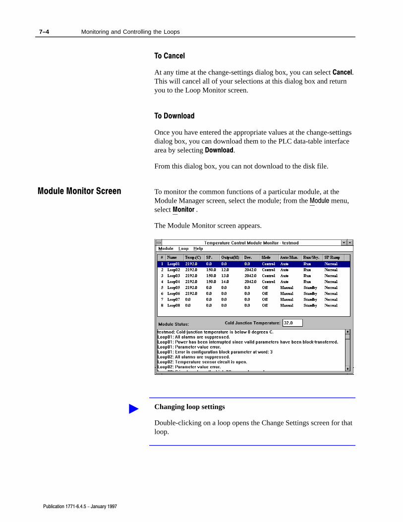
7–4 Monitoring and Controlling the Loops
Publication 1771�6.4.5 - January 1997
To Cancel
At any time at the change-settings dialog box, you can select Cancel.This will cancel all of your selections at this dialog box and returnyou to the Loop Monitor screen.
To Download
Once you have entered the appropriate values at the change-settingsdialog box, you can download them to the PLC data-table interfacearea by selecting Download.
From this dialog box, you can not download to the disk file.
To monitor the common functions of a particular module, at theModule Manager screen, select the module; from the Module menu,select Monitor .
The Module Monitor screen appears.
Changing loop settings
Double-clicking on a loop opens the Change Settings screen for thatloop.
Module Monitor Screen
�

Chapter 8
Publication 1771�6.4.5 - January 1997
Documenting Projects,Modules, and Loops
This chapter shows you how to use the Temperature Control ModuleConfiguration software to produce a printed record of your system,including descriptive information for each project, module, and loop,as well as the values of all configuration parameters. This includes:
• reports
• printing or viewing an entire project
• printing a single module or loop
You can generate reports for an entire project, an individual module(including its loops), or an individual loop. Each section of thereport includes a header showing the name of the item and itsdescriptive information, and a list of all the parameters that are partof the item, with the current value of each parameter also listed.
You can print reports on a printer attached to your computer, usingthe Print option, or you can view them on the screen, using the PrintPreview option. These reports can display either the online (i.e. PLCprocessor) data values, or the offline (i.e. File) data values.
To print or view an entire project:
1. Open the Module Manager screen on the desired project.
2. From the Project menu, select Print to produce a printed report, orPrint Preview to view the report on the screen.
A dialog box appears, prompting you to select File or PLC.
3. Select the set of values you wish to document.
The Print dialog box appears.
4. Make sure the All box is checked; if you are printing to a printer,be sure the printer information is correct and click on OK.
The report is printed or displayed on the screen.
Reports
Printing or Viewing anEntire Project

8–2 Documenting Projects, Modules, and Loops
Publication 1771�6.4.5 - January 1997
To print a single module or loop:
1. Open the Module Manager screen on the project containing themodule or loop you wish to document.
2. Select the module or loop you wish to document.
3. From the Project menu, select Print to produce a printed report, orPrint Preview to view the report on the screen.
A dialog box appears, prompting you to select File or PLC.
4. Select the set of values you wish to document.
The Print dialog box appears.
5. Make sure the Selection box is checked; if you are printing to aprinter, be sure the printer information is correct and click on OK.
The report is printed or displayed on the screen.
Printing a Single Moduleor Loop

A
alarmdead band, 5-6hysteresis, 5-6
audience, P-1
auto�tuning, 6-4
B
barrel/non-barrel, 5-3
block�transfer, 1-2
C
changing loop settings, 7-3
communication, how data is transferred, 1-2
computer requirements, 2-1
configuration selections, 5-2
configuring the loops, 5-1
configuring the module, 5-1
organizing the project file, 3-1
Alarms, 5-5
controlling and monitoring loops, 7-1
D
dead band, 5-6
definitions, P-2
disks, 2-2
drive convention, 2-2
E
error messages, 7-2
F
fine�tuning, 6-6
H
help, 2-2, 2-10
hysteresis, 5-6
I
inner/outer zone, 5-4
installation, software, 2-1
installation procedure, software, 2-2
installing the utility software, 2-1
installing Win32s files, 2-3
L
loop configuration, 5-1
loop list generation procedure, 5-1
loop monitor sreen, 7-1
module monitor sreen, 7-4
M
module configuration, 5-1
project list organization, 3-1
module list generation procedure, 3-1
module status, 7-2
monitoring and controlling loops, 7-1
monitoring auto�tuning results, 6-5
O
online help, 2-2, 2-10
open-circuit detection, 5-2
outer/inner zone, 5-4
P
PID loops, 1-2
procedure, loop list generation, 5-1
procedure, module list generation, 3-1
R
related publications, P-2
requirements for your computer, 2-1
S
selections, configuration, 5-2
Index

IndexI–2
set�point ramping, 7-1
single�transfer, 1-2
software disks, 2-2
software installation procedure, 2-2
software interface with PLC processors, 1-3
software, starting, 2-9
starting the software, 2-9
T
TC break detection, 5-2
terms, P-2
thermal integrity loss detection, 5-4
thermal runaway, 5-4
TPO, P-2, 5-6
tuning, 6-1auto�, 6-4fine�, 6-6
tuning assistant, 6-4
V
vocabulary, P-2
W
project file, 3-1
temperature control project file, 3-1

Publication 1771�6.4.5 - January 1997
If you need additional assistance on using your software,Allen-Bradley offers telephone and on-site product support atCustomer Support Centers worldwide
For technical assistance on the telephone, first contact your localsales office, distributor, or system integrator. If additional assistanceis needed, then contact your local Customer Support Center orcontact System Support Services.
For assistance that requires on-site support, contact your local salesoffice, distributor, or system integrator. During non-office hours,contact the Allen-Bradley 24-hour Hot Line at: 1-800-422-4913 inthe United States or contact your local Customer Support Centeroutside the United States.
Customer Support Center phone numbers:
Region or Area Customer Support Center TelephoneNumber
United States (Cleveland) 216�646�6800
Canada (Cambridge, Ontario) 519�623�1810
Latin America (Milwakee) 414�382�2000
United Kingdom (Milton Keynes) 44�908�838800
Europe (Amsterdam) 31�2975�43500
France (Paris) (33�1) 4778�1402
Germany (Gruiten) (49) 2104�6900
Italy (Milan) (39�2) 4830�0381
Asia Pacific (Hong Kong) (852) 873�1342
Customer Support

Publication 1771�6.4.5 - January 1997
Allen�Bradley, a Rockwell Automation Business, has been helping its customers improveproductivity and quality for more than 90 years. We design, manufacture and support a broadrange of automation products worldwide. They include logic processors, power and motioncontrol devices, operator interfaces, sensors and a variety of software. Rockwell is one of theworld's leading technology companies.
Worldwide representation.
Argentina • Australia • Austria • Bahrain • Belgium • Brazil • Bulgaria • Canada • Chile • China, PRC • Colombia • Costa Rica • Croatia • Cyprus • Czech Republic •Denmark • Ecuador • Egypt • El Salvador • Finland • France • Germany • Greece • Guatemala • Honduras • Hong Kong • Hungary • Iceland • India • Indonesia •
Ireland • Israel • Italy • Jamaica • Japan • Jordan • Korea • Kuwait • Lebanon • Malaysia • Mexico • Netherlands • New Zealand • Norway • Pakistan • Peru •Philippines • Poland • Portugal • Puerto Rico • Qatar • Romania • Russia-CIS • Saudi Arabia • Singapore • Slovakia • Slovenia • South Africa, Republic • Spain •Sweden • Switzerland • Taiwan • Thailand • Turkey • United Arab Emirates • United Kingdom • United States • Uruguay • Venezuela • Yugoslavia
Allen�Bradley Headquarters, 1201 South Second Street, Milwaukee, WI 53204 USA, Tel: (1) 414 382�2000 Fax: (1) 414 382�4444
Publication 1771�6.4.5 - January 1997 PN 955124�21Copyright 1997 Allen�Bradley Company, Inc. Printed in USA