山推 BYD4208 变速箱维修手册
58
山推 BYD4208 变速箱维修手册
Transcript of 山推 BYD4208 变速箱维修手册

山推 BYD4208 变速箱维修手册


BD05 Transmission Service Manual
Foreword
This service manual mainly covers the working principle, service instructions, service technology
and standard requirements for BD05 transmission (also applies to ZL15 series transmission), so as
to help service personnel understand the method of removing and refitting it and to lay a solid
technical foundation for them concerning the fault determination and proper service.
This service manual mainly includes the following:
Chapter 1 Introduction
This chapter mainly describes precautions for servicing transmission, the meaning of all symbols
which are included in the following text and the tightening torque for plain bolts.
Chapter 2 Transmission system
This chapter mainly describes the gearshift principle of transmission, the transmission line in each
gear, and the operation and maintenance of oil supply line and transmission.
Chapter 3 Removal of transmission
This chapter describes how to remove each part properly and the relevant precautions in the
process.
Chapter 4 Refitting of transmission
This chapter describes how to refit each part properly and the relevant precautions in the process.
Chapter 5 Service tools for transmission
This chapter describes special tools and conventional tools used in the working process.
Chapter 6 Transmission fault diagnosis and troubleshooting
This chapter describes the troubleshooting of common faults for the transmission.
Note
The specifications of parts covered by this Manual may be subject to modification due to the
improvement of this product, and no further notice will be given upon such modification, so
please contact SDLG for the latest data.


BD05 Transmission Service Manual
I
Contents 1 Introduction ................................................................................................................ 1
1.1 Safety precautions ............................................................................................. 1
1.2 Description of signs ........................................................................................... 3
1.3 Tightening torque table for plain bolts .............................................................. 3
2 Transmission system .................................................................................................. 5
2.1 Description of transmission ............................................................................... 5
2.2 Basic parameters of transmission & torque converter ...................................... 6
2.3 Structure and principle of transmission ............................................................. 6
2.3.1 Structure of transmission ........................................................................... 6
2.3.2 Gearshift principle of transmission ............................................................ 7
2.3.3 Transmission line of each gear .................................................................. 7
2.3.4 Structure and principle of gearshift clutch ................................................ 8
2.4 Oil supply system ............................................................................................ 11
2.4.1 Oil supply line and principle of transmission & torque converter oil
supply system .................................................................................................... 11
2.4.2 Description of main parts of oil supply system ....................................... 12
2.5 Operation and maintenance of transmission ................................................... 15
2.5.1 Precautions for installing transmission .................................................... 15
2.5.2 Maintenance of transmission ................................................................... 15
3 Removal of transmission .......................................................................................... 17
3.1 Removal of assembly ...................................................................................... 17
3.2 Removal of assembly ...................................................................................... 26
3.2.1 Removal of clutch assembly .................................................................... 26
3.2.2 Removal of transmission control valve ................................................... 29
4 Refitting of Transmission ......................................................................................... 32
4.1 Refitting of assembly components .................................................................. 32
4.1.1 Refitting of transmission control valve ................................................... 32
4.1.2 Refitting of clutch .................................................................................... 33

BD05 Transmission Service Manual
II
4.2 Refitting of assembly ....................................................................................... 37
4.2.1 Refitting of output shaft assembly and parking brake ............................. 37
4.2.2 Refitting of two clutch shafts and countershaft assembly ....................... 40
5 Service tools for transmission .................................................................................. 47
6 Fault Diagnosis and Troubleshooting of Transmission ............................................ 48

BD05 Transmission Service Manual
1
1 Introduction
1.1 Safety precautions
Important safety notice
Service and maintenance is essential to the safe operation of vehicle. This Manual mainly
states how to remove and refit transmission assembly.
To prevent relevant personnel from being hurt, this Manual takes as a safety sign. With
regard to precautions attached with this sign, it is required to do operation carefully. In case
of potential hazard, first take into account the safety of yourself, and meanwhile take
necessary protective measures.
Safety notice
In the process of removal and refitting, improper operation methods will lead to part damage,
service life shortening and operating performance deterioration, and in addition, it may cause
personal injury. Therefore, please read related content in this Manual carefully before removing
and refitting any part.
1. The parameters, figures and content covered by this Manual apply to products of standard
configuration. As regard to variants, please consult SDLG or relevant data.
2. In the repair workshop, a separate or special area shall be provided for removal and refitting of
parts or for removed parts, corresponding tools and parts shall be placed at an appropriate area,
and the operation area shall be kept clean and free of oil dirt and other contaminant. Do not smoke
at any place other than the specified smoking area. Never smoke during operation, and it is
required to provide fire extinguishing device.
3. When welding operation is required, it shall be done by a trained and experienced welding
worker. During welding operation, it is required to use shield and wear appropriate protective
equipment such as welding gloves, blind, goggles, work cap and overall.
4. Before removing transmission & torque converter, be sure to clean dirt from the external
surface so as to prevent parts from being contaminated during removal.
5. During operation, do wear safety shoes and safety helmet. Do not wear inappropriate overall.
The overall must be buttoned. When striking parts with a copper rod, wear goggles.

BD05 Transmission Service Manual
2
6. Petrol, kerosene and water-based oil cleaner can be used to clean removed parts.
7. When using a crane or other hoisting equipment, first check the slings for damage. It is required
to use hoisting equipment with sufficient lifting capacity. During lifting operation, do lifting
operation slowly at appointed position so as to prevent parts from colliding with each other. Do
not work under lifted parts.
8. When two or more persons are required to work simultaneously, they shall be in agreement
with the same operation procedure to avoid accident due to out of step.
9. Be sure to keep all tools properly and get familiar with their operating methods.
10. To align one hole with another, do not insert your hand or finger into the holes. As regards to
parts requiring assembly with hands, pay attention to the holding position and check it for risk of
crushing.
11. Be sure to perform inspection on the removed parts. The part of which the defect has already
affected the performance must be replaced.
12. After each part is fitted, no interference is allowed.
13. When passing the oil seal and the seal ring through key groove, threaded hole and step during
installation, take corresponding protective measures so as to avoid damaging them.
14. In the process of assembling parts, the tools used shall match corresponding threaded fasteners
so as to prevent the fasteners from being damaged.
15. To tighten fittings body and plug screw, do not use a pneumatic wrench. Be sure to rotate them
to some extent by hand, and then use a torque wrench of corresponding specification to tighten
them to required torque.
16. When draining oil from the transmission, be sure to unscrew the drain plug slowly so as to
prevent oil from spurting out.

BD05 Transmission Service Manual
3
1.2 Description of signs
To make this Manual fully play its roles, the signs in Table 1-1 are used in respect of important
safety and quality requirements.
Table 1-1
Sign Item Remarks
Safety
During operation, pay special attention to safety.
During operation, pay special attention to safety because of
inside pressure.
Note
During operation, pay special attention to technical
requirements so as to ensure operation quality.
Weight
Weight of component or device and removal & refitting
modes
Pay attention to the selection of sling and the posture
during operation.
Tightening
torque Pay special attention to tightening torque during assembly.
Application Points requiring the application of adhesive and grease
Oil and
water Add a certain amount of oil, water and fuel.
Draining
Position for draining oil or water, as well as draining
amount
1.3 Tightening torque table for plain bolts
Table 1-2
Strength class
of bolt
Yield
strength
N/mm2
Nominal diameter of bolt, mm
6 8 10 12 14
Tightening torque, Nm
8.8 640 9~12 22~30 45~59 78~104 124~165
10.9 900 13~16 30~36 65~78 110~130 180~210

BD05 Transmission Service Manual
4
12.9 1080 16~21 38~51 75~100 131~175 209~278
Strength class
of bolt
Yield
strength
N/ mm2
Nominal diameter of bolt, mm
16 18 20 22 24
Tightening torque, Nm
8.8 640 193~257 264~354 376~502 521~683 651~868
10.9 900 280~330 380~450 540~650 740~880 940~1120
12.9 1080 326~434 448~597 635~847 864~1152 1098~1464
Strength class
of bolt
Yield
strength,
N/ mm2
Nominal diameter of bolt, mm
27 30 33 36 39
Tightening torque, Nm
8.8 640 952~1269 1293~1723 1759~2345 2259~3012 2923~3898
10.9 900 1400~1650 1700~2000 2473~3298 2800~3350 4111~5481
12.9 1080 1606~2142 2181~2908 2968~3958 3812~5082 4933~6577

BD05 Transmission Service Manual
5
2 Transmission system
2.1 Description of transmission
The BD05 transmission is a fixed shaft, constant mesh and power gearshift transmission, which is
mainly used for LG918 and LG920 loaders. The ZL15 series transmission is mainly used for the
LG916D loader. In the transmission system of LG916D, LG918 or LG920 loader, the engine is
directly connected to the torque converter via the spring plate so as to realize output power. The
torque converter is connected via the propeller shaft to the front input flange of transmission
which changes speed, increases torque and then transmit power to front and rear drive axles via
front and rear propeller shafts respectively.
The BD05 transmission mainly consists of input shaft assembly, forward low-gear clutch shaft
assembly, reverse high-gear clutch shaft assembly, countershaft assembly and output shaft
assembly.
Fig. 2-1
1. Breather 2. Input shaft assembly 3. Transmission mounting bracket 4. Reverse high-gear clutch
shaft assembly 5. Forward low-gear clutch shaft assembly 6. Oil suction port 7. Transmission
control valve 8. Parking brake 9 Countershaft assembly 10. Oil inspection plug 11. Output shaft
assembly

BD05 Transmission Service Manual
6
2.2 Basic parameters of transmission & torque converter
Table 2-1
Item Parameters/description
Torque
converter
Type Single-stage three-element single-turbine
torque converter
Oil pressure at torque converter
inlet (MPa) 0.4~0.6
Oil pressure at torque converter
outlet (MPa) 0.15~0.325
Transmission
Type Fixed-shaft power gearshift
Gears Forward II, reverse II
Transmission working pressure
(MPa) 1.2~1.5
2.3 Structure and principle of transmission
2.3.1 Structure of transmission
Fig. 2-2 Schematic diagram of transmission structure

BD05 Transmission Service Manual
7
2.3.2 Gearshift principle of transmission
The transmission adopts mechanical gearshift. The gearshift mechanism of BD05 transmission is
shown in Fig. 2-3. This gearshift mechanism includes two gearshift levers: 1. Direction control
lever; 2. High/low speed control lever. They are connected to the transmission control valve stem
of the transmission respectively via the flexible shaft, so the working of clutch of each gear is
realized by controlling the transmission valve. The working condition of each clutch is shown in
Fig. 2-4.
Fig. 2-3 Gear selector Fig. 2-4 Working condition of clutch for each gear
2.3.3 Transmission line of each gear
1. Transmission line of forward I 2. Transmission line of forward II
Fig. 2-5
Z1→Z2→Z4→Z6→Z7→Z8→Z9→Z10→Z11
Fig. 2-6
Z1→Z2→Z4→Z5→Z7→Z8→Z9→Z10→Z11
Gear Clutch
Neutral

BD05 Transmission Service Manual
8
3. Transmission line of reverse I 4. Transmission line of reverse II
Fig. 2-7
Z1→Z3→Z5→Z4→Z6→Z7→Z8→Z9→Z10→Z11
Fig. 2-8
Z1→Z3→Z5→Z7→Z8→Z9→Z10→Z11
2.3.4 Structure and principle of gearshift clutch
(1) Composition and structure
The BD05 transmission is equipped with four groups of normally-released clutches, which are
engaged by means of transmission oil so as to fulfill the functions of two forward and two reverse
gears. Two groups therein are directional clutches for forward and reverse traveling. The input
gear meshes with forward and reverse clutch gears at the same time. For each gear, one direction
clutch and one speed clutch work together. The power from the clutch shaft assembly is
transmitted to the countershaft assembly, then to the output shaft via the gear of the former, and
finally is output by means of forward and rear output flanges.

BD05 Transmission Service Manual
9
Fig. 2-9
1 Forward gear clutch 2. Low speed gear clutch 3. Reverse gear clutch 4. High speed gear clutch
(2) Working principle
The structures of these four clutches are similar. There are four pieces of drive plates and driven
plates for each clutch. The external spline of gear is connected to the internal spline of drive plate,
and the internal spline of clutch housing is connected to the external spline of driven plate. One
end of return spring is against the piston, and the other end supports the shaft via the spring seat
and the retainer ring. Two clutches share one shaft. The oil supply to the two cylinders and the
lubrication of clutches and gears are all provided by the oil path of the shaft.
When operating: when gearshift is performed, pressurized oil enters piston chamber via internal
oil path, forces piston to overcome spring force and move, and the piston pushes drive plate to
press against driven plate. Thus the clutch is engaged.
When operation is stopped: pressurized oil is cut off, so the transmission oil in the cylinder
returns via oil return port, and the piston returns under the effect of return spring, in this case, the
internal and outer friction linings detach. Thus the gear idles.

BD05 Transmission Service Manual
10
Fig. 2-10 Structure of clutch
1. Constant-mesh gear 2. Bearing plate 3. Snap ring 4. Clutch housing 5. Piston
6. Separation bracket 7. Outer friction lining 8. Inner friction lining 9. Spring
10. Clutch shaft 11. Working oil path 12. Lubrication oil path 13. Snap ring
(3) Working principle of automatic drain valve
After oil supply to the clutch cylinder is stopped, the clutch housing continues to rotate with the
shaft under the effect of inertia force, the transmission oil in the cylinder is thrown outward under
the centrifugal force, pressure forms around the circumferential edge of cylinder, force is
generated to push the piston to return, and thus prevent the clutch from being released rapidly. To
unload the centrifugal pressure of oil in the rotary cylinder, an automatic drain valve is installed
on the clutch housing.
When clutch is engaged:
Pressurized oil enters the cylinder, and flows out from the drain port via the path between the steel
ball and the port. At this moment, pressure difference is generated between the front and the rear
sides of the steel ball. Under the effect of this pressure difference, the steel ball is forced to move
towards the drain port till the port is closed. The draining is stopped, and the oil pressure in the
cylinder rises.
When clutch is released:
The cylinder and the oil return path are connected to unload pressure. At this moment, without the

BD05 Transmission Service Manual
11
effect of pressurized oil, steel ball is thrown outward under the centrifugal force, and then the
drain port is opened. The oil in the cylinder flows out from the drain port via the path between the
steel ball and the port and pushes the piston to return rapidly.
When clutch is engaged When clutch is released
Fig. 2-11 Working schematic of drain valve
1. Piston 2. Clutch cylinder 3. Steel ball
2.4 Oil supply system
2.4.1 Oil supply line and principle of transmission & torque converter oil
supply system
(1) Oil supply line of oil supply system
The oil supply system is an important component of hydromechanical transmission system. It
mainly consists of radiator, secondary filter, oil filter, transmission pump, relief valve,
transmission control valve and each pipeline.
Fig. 2-12 Oil supply line diagram
1. Radiator 2. Secondary filter 3. Transmission pump 4. Radiator oil inlet pipe 5. Oil suction pipe

BD05 Transmission Service Manual
12
6. Torque converter oil return pipe 7. Radiator oil outlet pipe 8. Relief valve oil inlet pipe
9. Relief valve 10. Transmission control valve oil inlet pipe 11. Oil distributor
12. Transmission control valve
(2) Oil supply principle
The transmission pump sucks transmission oil from the oil sump via strainer and delivers it to the
oil filter, after being purified, the oil enters relief valve. The relief valve has four oil ports of
which one directly is connected to the torque converter via valve body and the other three to the
transmission valve, transmission pressure gauge and transmission oil filler (oil return pipe)
respectively.
At the port connected to the transmission valve, the pressurized oil enters the oil inlet end cap via
the connecting pipe (steel pipe in diameter equal to 6 mm) inside the housing, and then flows to
each clutch cylinder. The oil outlet of torque converter is equipped with one tee union (equipped
with oil temperature sensor) through which the used oil enters oil cooler for cooling and then
flows to the common oil inlet port of transmission end cap for the lubrication and cooling of
inside parts (such as clutch) of transmission.
2.4.2 Description of main parts of oil supply system
(1) Transmission control valve
Constitution and structure:
The transmission control valve consists of speed valve, directional valve, shut-off valve and valve
body (see Fig. 2-13). The speed valve consists of speed valve stem, spring and steel ball. Pull the
speed valve stem to engage the transmission in the 1st gear, neutral gear and 2nd gear
respectively.
The directional valve consists of directional valve stem, spring and steel ball. Pull the directional
valve stem to engage the transmission in the forward gear, neutral gear and reverse gear
respectively.
Shut-off valve: the shut-off valve consists of control valve assembly, valve core and spring.

BD05 Transmission Service Manual
13
Fig. 2-13 Schematic diagram of transmission control valve structure
1. Valve body 2. Speed valve stem 3. Directional valve stem 4. Spring 5. Spring
6. Shut-off valve core 7. Oil seal 8. Shut-off piston 9. Steel ball
Working principle:
The combination of directional valve and speed valve can realize the function of forward I & II
and reverse I & II. For example, when the directional valve stem is pulled out, the pressurized oil
from the main regulator valve enters the directional valve and then flows to transmission forward
clutch via port a. The pressurized oil pushes the piston to make the drive plate of the clutch press
against the driven plate, and thus the transmission engages in the forward gear. When the speed
valve is in 1st gear or 2nd gear, the forward I or II is realized. Similarly, when the directional
valve stem is pressed down, the pressurized oil enters transmission reverse clutch via port b. The
pressurized oil pushes piston to make the drive plate of the clutch press against the driven plate,
and thus transmission engages with reverse I or II.
When the loader is traveling and the brake pedal is free, the shut-off valve is in the middle
position. When the brake pedal is depressed, the pressurized oil from the brake system enters the
oil control chamber and pushes the piston, the piston pushes the valve stem to move the valve
core, and thus the spring is compressed. At this moment, the shut-off valve core will cut the path
(port a and port b) from selector valve to transmission clutch, the forward or reverse clutch is
released, and no power is transmitted. This is not only helpful for loader braking, but also can
make loader apply all force on working device during shovel operation.

BD05 Transmission Service Manual
14
Fig. 2-14
1. Power shut-off valve 2. Main pressure test port 3. Transmission valve oil inlet
4. Transmission valve stem
(2) Relief valve
The relief valve mainly consists of transmission pressure valve and torque converter inlet pressure
valve. The transmission pressure valve can regulate the transmission operation pressure (1.2~1.5
MPa), and the torque converter inlet pressure valve can regulate the inlet oil pressure of torque
converter (0.4~0.6 MPa). There is an oil path on the relief valve for the lubrication of torque
converter internal gears. When the oil supply pressure in the system is too high, the overflow
valve inside of the relief valve opens to release pressure via the release port.
Fig. 2-15 Relief valve
1. Transmission pressure sensor 2. To transmission control valve pipe
3. Relief valve oil inlet pipe 4. Oil return pipe 5. Pressure regulating bolt

BD05 Transmission Service Manual
15
2.5 Operation and maintenance of transmission
2.5.1 Precautions for installing transmission
(1) When installing transmission, ensure the input of it is coaxial with the output of torque and the
output of transmission is coaxial with the input of front/rear axle.
(2) After transmission is fitted, add about 24 L 6# hydraulic transmission oil into it via the oil filler,
and check the oil level which shall reach the required position of dipstick after the engine runs for 5
min. Before and after each operation, check the oil level in the transmission.
(3) The shift between forward gear and reverse gear as well as between low gear and high gear shall
be done only after the loader is stopped. The shift between forward I and forward II or between
forward III and forward IV can be done when the loader is traveling.
(4) When the transmission is running, pay attention to the operation oil
pressure, it shall be kept in the range of 1.2~1.5 MPa. Normally, the
temperature of oil at outlet of torque converter shall not exceed 105℃,
and in a short term, it shall not exceed 115℃. The temperature of oil in
the transmission oil sump shall not exceed 100℃.
(5) Each control lever and mechanism shall be flexible, and no seizure
is allowed. The gear shift must be correct, and the hand feeling should
be obvious.
(6) Do not start the loader when the brake pedal is depressed and the opening of engine throttle
reaches the maximum.
(7) The hand brake must be adjusted properly so that it can work reliably.
2.5.2 Maintenance of transmission
(1) Change transmission oil for a new loader after 100 h for the first time and once every 500 h
thereafter. Add about 24 L 6# (8#) hydraulic transmission oil into it via the oil filler, and check the
oil level which shall reach the required position of dipstick after engine runs for 5 min. Before and
after each operation, check the oil level in the transmission.
(2) When transmission is running, pay attention to the operation oil pressure, it shall be kept in the
Fig. 2-16

BD05 Transmission Service Manual
16
range of 1.2~1.5 MPa. Normally, the temperature of oil at outlet of torque converter shall not
exceed 105℃, and in a short term it shall not exceed 115℃.
(3) When a new transmission is fitted, a 12 h running-in period is required. Run it for two hours
when it is in one of six gears. During the running-in period, the load shall not exceed 70% of the
rated load, and the oil temperature, oil level and the tightening conditions of bolts shall be noted.
After the running-in period, clean the transmission oil sump and the oil strainer.
(4) The shift between forward gear and reverse gear as well as between low gear and high gear
shall be done only after the loader is stopped. The shift between forward I and forward II or
between forward III and forward IV can be done when the loader is traveling.

BD05 Transmission Service Manual
17
3 Removal of transmission
3.1 Removal of assembly
Preparation before removal:
(1) Clean mud and dirt from the transmission and the torque converter completely.
(2) Remove the drain plug, and discharge transmission oil.
Hydraulic transmission oil: about 24 L
(3) Prepare a firm transmission assembly support.
Transmission & torque converter assembly: about 200 kg.
Fig. 3-1
1. Transmission bracket
1. Place the transmission on the maintenance
support.
Fig. 3-2
1. Transmission operation valve
2. Bolt
2. Remove the fixed bolt of transmission operation
valve, and take off the transmission control valve
and gasket.
NOTE:
Protect the sealing face and gasket.

BD05 Transmission Service Manual
18
Fig. 3-3
1. Tightening nut
2. Pressure plate
3. Remove the cotter pin from the tightening nut of
input flange with a pair of pliers. Remove the
tightening nut of input flange, and take off the
pressure plate.
NOTE:
Protect the cotter pin.
Fig. 3-4
1. Input flange 2. O-ring
4. Remove the O-ring and the input flange by hand.
NOTE:
Protect the O-ring.
Fig. 3-5
1. Oil distributor cap
5. Remove the bolts from the oil distributor cap of
reverse high-speed gear clutch.
NOTE:
If it is not easy to remove them, use a recoilless
hammer to strike the oil distributor cap slightly.

BD05 Transmission Service Manual
19
Fig. 3-6
1. Seal ring
2. Gasket
6. Remove the oil distributor cap and the seal ring.
NOTE:
Protect the sealing face and the gasket. Keep the
seal ring properly.
Fig. 3-7
1. Oil distributor cap
7. Remove the bolts from the oil distributor cap of
forward low-speed gear clutch assembly.
Fig. 3-8
1. Seal ring 2. Gasket
8. Remove the oil distributor cap.
NOTE:
Protect the sealing face and the gasket.
Keep the seal ring properly.

BD05 Transmission Service Manual
20
Fig. 3-9
1. Jackscrew
9. Remove the mounting bolt of transmission big
end cap. Install the jackscrew into the mounting
hole of housing end cap to eject the big end cap
out.
Jackscrew: M10
Fig. 3-10
10. Remove the transmission big end cap and paper
gasket.
NOTE:
Protect the sealing face and the gasket.
Fig. 3-11
1. Forward low-gear clutch assembly
11. Vertically remove the forward low-gear clutch
assembly with a crowbar.
NOTE:
When using a crowbar, protect the sealing face.

BD05 Transmission Service Manual
21
Fig. 3-12
1. Bolt 2. Jackscrew hole
3. End cap
12. Remove the bolt from the intermediate end cap,
and eject the end cap out with two jackscrews.
Jackscrew: M10
Fig. 3-13
1. Gasket 2. Pressure cap
13. Remove the bolts from the countershaft pressure
cap, slightly strike the pressure cap with a
recoilless hammer, remove it and the gasket, and
place them aside.
NOTE:
Protect the sealing face and the gasket.
Fig. 3-14
1. Countershaft bull gear
2. Spacer ring 3. Countershaft pinion
4. Retainer ring
14. Slightly strike the countershaft on the back with a
copper rod, and remove the countershaft
assembly from the front.
NOTE:
Record the installation sequence and direction of
each part.

BD05 Transmission Service Manual
22
Fig. 3-15
1. Forward low-gear clutch assembly
15. Remove the reverse high-speed gear clutch
assembly.
NOTE:
When using a crowbar, protect the sealing face.
Fig. 3-16
16. Remove bolts, and take off the oil sump and the
gasket.
NOTE:
Protect gasket.
Record the installation sequence and direction of
each gear and sleeve of the output shaft.
Fig. 3-17
1. Rear output flange
2. Cotter pin
17. Remove the cotter pin from the tightening nut of
rear output flange with a pair of pliers.
NOTE:
Protect the cotter pin.

BD05 Transmission Service Manual
23
Fig. 3-18
1. O-ring 2. Pressure plate
3. Tightening nut
18. Remove the tightening nut from the rear output
flange, and take off the pressure plate and the
O-ring.
NOTE:
When removing the nut, apply the brake.
Fig. 3-19
1. Jackscrew hole 2. Bolt
3. Rear end cap 4. Rear output flange
19. Take off the rear output flange, remove the bolts
from the rear end cap, and eject the rear end cap
out with two jackscrews.
Jackscrew: M10
Fig. 3-20
1. Cotter pin
2. Parking brake
20. Remove the cotter pin from the tightening nut of
output shaft front output flange.

BD05 Transmission Service Manual
24
Fig. 3-21
1. O-ring 2. Pressure plate
3. Tightening nut 4. Front output flange
21. Remove the tightening nut from the front output
flange, and take off the pressure plate, the O-ring
and the front output flange.
NOTE:
When removing the nut, apply the brake.
Fig. 3-22
1. Bolt 2. Parking brake
22. Unscrew the mounting bolts of parking brake,
and remove the parking brake.
Fig. 3-23
1. Bolt
2. Output shaft front end cap
23. Remove the mounting bolts of output shaft front
end cap, take off the front end cap, and place it
aside.
NOTE:
If it is not easy to remove the end cap, use a
recoilless hammer or copper rod to strike it.

BD05 Transmission Service Manual
25
Fig. 3-24
1. Output shaft
24. Use a copper rod to strike the output shaft on the
rear output flange side, and remove the output
shaft assembly, i.e., output shaft gear, spacer and
bearing.
Fig. 3-25
1. Output shaft assembly
25. Remove the output shaft assembly from the front
side of transmission.
NOTE:
The gear and sleeve of the shaft and the bearing
cone on the side of brake may fall down, so pay
attention to keeping it.
Fig. 3-26
1. Brake support
26. Remove the bolts, and eject the brake support out
with a jackscrew.

BD05 Transmission Service Manual
26
3.2 Removal of assembly
3.2.1 Removal of clutch assembly
Fig. 3-27
1. Forward low-gear clutch assembly
NOTE:
Because the structures of clutches are similar, take
the removal of forward gear clutch as an example, and
no details relating to others is given.
Fig. 3-28
1. Bearing
1. Remove the bearing with a crowbar.
Fig. 3-29
1. Retainer ring
2. Remove the retainer ring from the shaft.

BD05 Transmission Service Manual
27
Fig. 3-30
1. Gear
3. Use a crowbar to separate gear from the clutch.
Fig. 3-31
1. Bearing
4. Remove the bearing with a crowbar.
Fig. 3-32
1. Retainer ring
2. Spring shield
5. Press the spring shield with a crowbar, and
remove the retainer ring with a pair of snap ring
pliers. Remove the spring shield and the spring.

BD05 Transmission Service Manual
28
Fig. 3-33
1. Retainer ring
2. Bearing plate
6. Remove the retainer ring with a pair of snap ring
pliers. Remove the bearing plate of clutch friction
lining.
Fig. 3-34
1. Friction lining
7. Successively remove the outer friction lining, and
then the inner friction lining.
Fig. 3-35
1. Piston
8. Remove the piston.

BD05 Transmission Service Manual
29
3.2.2 Removal of transmission control
valve
Fig. 3-36
1. Unscrew the plug and washer from the locating
lock pin of valve stem, and remove spring and
steel ball.
Fig. 3-37
1. Plug screw
2. Remove the locating screw plug of forward &
reverse valve core.
Fig. 3-38
1. O-ring 2. Locating guide
3. Spring 4. Steel ball
3. Successively remove O-ring, locating guide rod,
spring and steel ball.

BD05 Transmission Service Manual
30
Fig. 3-39
1. Forward & reverse valve cores
4. Take out the forward & reverse control valve
core.
Fig. 3-40
1. Forward & reverse control valve plug
screw
2. Shut-off valve screw plug
3. High & low speed control valve screw
plug
5. Remove the plug screws of the three valve cores,
and take off the O-rings.

BD05 Transmission Service Manual
31
Fig. 3-41
1. Shut-off valve core
2. Shut-off valve control valve body
6. Unscrew the shut-off control valve body and the
joint on it.
Fig. 3-42
1. Spring
7. Take out the shut-off valve spring and the valve
core.

BD05 Transmission Service Manual
32
4 Refitting of Transmission
4.1 Refitting of assembly components
NOTE:
Clean each component before refitting.
4.1.1 Refitting of transmission control valve
Fig. 4-1
1. Forward & reverse control valve core
2. High & low speed control valve core
1. Insert all the control valve cores.
Fig. 4-2
2. Tighten the plug screw of all valve cores.

BD05 Transmission Service Manual
33
Fig. 4-3
1. O-ring 2. Locating guide
3. Spring 4. Steel ball
3. Successively insert the locating assembly of
forward & reverse control valve core and tighten
the plug screw.
NOTE:
Install the locating assembly of high & low speed
control valve core in the same sequence as above.
4.1.2 Refitting of clutch
NOTE:
The structures of the two clutch shaft assemblies
are similar, here take the refitting of forward
clutch of input shaft assembly as an example, and
no details relating to the other is given.
Fig. 4-4
1. Pressurized oil surface
2. Friction lining surface
1. Install the internal and external seal rings onto
the piston.
NOTE:
The big end of seal ring should face towards the
pressurized oil surface.

BD05 Transmission Service Manual
34
Fig. 4-5
1. Piston
2. Put the piston into the clutch.
Fig. 4-6
1. Piston
2. Return spring
3. Snap ring
4. Spring retainer
3. Successively install the return spring and the
spring shield onto the clutch shaft. Press the
return spring with a crowbar and then install the
snap ring.
Fig. 4-7
1. Bearing
2. Retainer ring
4. Successively install the bearing and the retainer
ring onto the clutch shaft.

BD05 Transmission Service Manual
35
Fig. 4-8
1. Bearing
2. Low speed gear
5. Install the low speed gear and the bearing onto
the clutch shaft.
Fig. 4-9
1. Outer friction lining
6. Place the outer friction lining into the clutch.
Fig. 4-10
1. Inner friction lining
7. Alternatively place internal and outer friction
linings into the clutch.

BD05 Transmission Service Manual
36
Fig. 4-11
1. Inner friction lining
2. Outer friction lining
8. After the installation of internal and outer friction
linings, install the bearing plate into the clutch.
NOTE:
In the four groups of clutches, there are 4 internal
friction lings and 4 outer friction linings.
The specifications of all inner friction linings are
the same, so are those outer friction linings.
During replacement, it is required to replace the
friction ling involved, and ensure the number of
the friction linings and the fitting sequence are
correct.
Fig. 4-12
1. Retainer ring
2. Bearing plate
9. Install the bearing plate, and use a circlip plier to
install the retainer ring of clutch bearing plate.
Fig. 4-13
1. Retainer ring
10. Install the retainer ring onto the clutch shaft.

BD05 Transmission Service Manual
37
Fig. 4-14
1. Bearing
11. Install the bearing onto the clutch shaft in
position.
Fig. 4-15
1. Seal ring
12. Install three seal rings onto the clutch shaft.
NOTE:
● The piston ring is made of cast iron which is
very brittle, thus the force applied during
installation should be uniform to avoid damage.
● The openings of the two seal rings should
stagger 120° against each other and also in
relation to the oil inlet path.
4.2 Refitting of assembly
4.2.1 Refitting of output shaft assembly
and parking brake
Fig. 4-16
1. Bolt
2. Front output end cap
1. With the oil inlet cap of transmission housing
upwards, install the output shaft front end cap
onto the housing, apply 515 sealant evenly to the
sealing surface, and tighten the bolts.
NOTE:
Check and replace oil seals in the end cap.
: 78~104Nm

BD05 Transmission Service Manual
38
: 515 sealant
Fig. 4-17
1. Bearing
2. Output shaft
3. Output shaft gear
2. With the section connecting to torque converter
upwards, place the spacer on the bearing and then
the output gear on the spacer; after this, install
the output shaft onto the output gear, the spacer
and the bearing.
Fig. 4-18
Adjusting method
Measure the distance H1 between the output gear
plane and the housing plane, and distance H2
between the bearing cone plane and bearing
pedestal connecting section, and if
H2-H1-δ=0.1~0.13, install adjusting shims with a
thickness of δ onto the gear end face.
Fig. 4-19
1. Jackscrew hole 2. Bolt
3. Bearing pedestal 4. Front output flange
3. Install the bearing pedestal assembly onto the
housing, the front output flange, the O-ring and
pressure plate successively, and tighten the fixing
nut of output flange.
: 78~104Nm

BD05 Transmission Service Manual
39
Fig. 4-20
1. O ring 2. Pressure plate
3. Fixing nut
4. Fit the cotter pin to the fixing nut onto the output
shaft front output flange.
Fig. 4-21
1. Bolt
2. Parking brake
5. Install the output shaft rear end cap, and tighten
the fixing bolts. Install the rear output flange.
NOTE:
Check and replace the oil seal in the end cap.
Fig. 4-22
1. O-ring 2. Pressure plate
3. Fixing nut 4. Front output flange
6. After installing the O-ring and pressure plate,
tighten the fixing nut of rear output flange.
NOTE:
When tightening nuts, apply the parking brake.

BD05 Transmission Service Manual
40
Fig. 4-23
1. Cotter pin
2. Parking brake
7. Install the parking brake, and tighten the fixing
bolts.
: 78~104Nm
4.2.2 Refitting of two clutch shafts and
countershaft assembly
Fig. 4-24
1. Reverse gear shaft assembly
2. Countershaft assembly
1. With the face connecting the housing with the
torque converter upwards, install the high-speed
reverse clutch assembly into the housing.
NOTE:
Screw in the clutch.

BD05 Transmission Service Manual
41
Fig. 4-25
1. Gasket 2. Pressure cap
2. Install the countershaft pressure cap and gaskets,
and tighten the fixing bolts. Apply 515 sealant
evenly to the sealing surface.
NOTE:
Check and replace the gasket.
:78~104Nm
: 515 sealant
Fig. 4-26
1. Countershaft bull gear
2. Spacer ring 3. Countershaft pinion
4. Retainer ring
3. Put the countershaft assembly into the housing in
the sequence as shown left, then insert the
countershaft, and finally install the bearing on the
countershaft.
NOTE:
Ensure that each pair of gears mesh properly.
Fig. 4-27
1. Countershaft assembly
4. Install the countershaft assembly in position.
Rear o
utp
ut flan
ge sid
e
Park
ing b
rake sid
e

BD05 Transmission Service Manual
42
Fig. 4-28
Adjusting method
After bearing is fitted in place, measure the
distance H1 between the bearing end face and the
housing end face, and the height H2 of
countershaft rear end cap stop, and if
H1-H2-δ=0.1~0.15., install adjusting shims with a
thickness of δ onto the bearing.
Fig. 4-29
1. Bolt
2. End cap
5. Install O-ring onto the countershaft rear end cap,
and then install the countershaft end cap; after
that, tighten the bolts.
:45~59Nm
Fig. 4-30
1. Low-speed forward clutch assembly
6. Install the low speed forward clutch into the
housing.
NOTE:
Screw in the clutch by rotating, always with the
two clutch gears and the countershaft gear meshed
properly.

BD05 Transmission Service Manual
43
Fig. 4-31
1. Big end cap
7. Install the housing big end cap and the gasket.
NOTE:
Check and replace the gasket.
Fig. 4-32
1. Bolt
8. Tighten the fixing bolts of the big end cap.
Fig. 4-33
1. Skelton oil seal
2. Input bearing support
3. O-ring
9. Install the O-ring and the skeleton oil seal into
the input bearing pedestal, and then install the
input bearing pedestal into the big end cap.
NOTE:
Check and replace the gasket.

BD05 Transmission Service Manual
44
Fig. 4-34
1. Bolt
10. Tighten the fixing bolts of input bearing pedestal.
Fig. 4-35
1. Input flange 2. O-ring 3. Pressure plate
11. Install the input flange with the O-ring and the
pressure plate.
Fig. 4-36
1. Fixing nut
2. Cotter pin
12. Tighten the fixing nut of output flange, and
install the cotter pin.

BD05 Transmission Service Manual
45
Fig. 4-37
1. Bolt
2. Oil distributor cap
13. Apply 515 sealant evenly to the oil inlet cap
surface, install the oil distributor cap of reverse
high speed reverse clutch assembly and the
gasket, and tighten the bolts.
NOTE:
Do not apply sealant to the O -ring. Prevent
damaging any seal ring when installing oil inlet
cap.
: 45~59Nm
: 515 sealant
Fig. 4-38
1. Oil distributor cap
2. Bolt
14. As described above, install the oil distributor cap
of low speed forward clutch and the gasket, and
tighten the bolts.
Fig. 4-39
1. Bolt
15. Tighten the bolts connecting the oil sump and the
housing, and install the gasket.
NOTE:
Check and replace the gasket.
The bolts should be tightened diagonally and
repeatedly.

BD05 Transmission Service Manual
46
Fig. 4-40
1. Bolt
2. Transmission control valve
16. Install the transmission control valve and the
gasket, and tighten the fixing bolts.
NOTE:
Check and replace the gasket.
: 45~59Nm

BD05 Transmission Service Manual
47
5 Service tools for transmission
Table 5-1
Special tool Designation Applicable position Remarks
Transmission
support
To support and tilt the
transmission
If not available, a
removal platform
can be set up.
Depth meter Countershaft and output shaft Specification:
0.02/0~200
Transmission
pressure joint Relief valve pressure joint 6410006223
Pressure testing hose Used with the pressure test joint
and pressure gauge 4030000368
Pressure gauge with
a range of 25 bar 6430000943

BD05 Transmission Service Manual
48
6 Fault Diagnosis and Troubleshooting of Transmission
Table 6-1
Symptoms Probable causes Solution
1. Gear engaging failure
1. The gear engaged is
incorrect.
1. Engage it again or check the
transmission control valve.
2. The clutch piston leaks oil. 2. Disassemble, check, or
replace the rectangle ring.
3. The transmission pressure is
low.
3. Do troubleshooting as
described below.
4. The housing oil passage is
blocked.
4. Disassemble, clean and
unblock it.
2. Low transmission
pressure
1. The main regulator valve is
improperly adjusted or the
spring is in failure.
1. Readjust it or replace the
spring.
2. The transmission oil level is
too low.
2. Add oil up to the oil mark.
3. The strainer or oil path is
clogged up.
3. Clean or unclog it.
4. The clutch leaks oil. 4. Replace the rectangle ring.
5. The transmission pump is in
failure.
5. Check and replace.
3. High oil temperature
1. The operation time is too
long.
1. Stop the vehicle or run it at
idle speed for a while.
2. The oil in the transmission is
insufficient or excessive.
2. Add oil up to the overflow
hole.
3. The clutch plate skids. 3. Check oil pressure and seal
ring.
4. The clutch cannot be 4. Check the clutch control oil
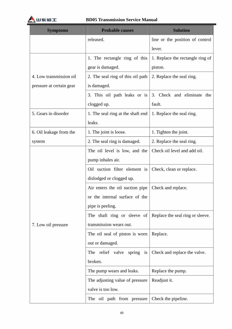
BD05 Transmission Service Manual
49
Symptoms Probable causes Solution
released. line or the position of control
lever.
4. Low transmission oil
pressure at certain gear
1. The rectangle ring of this
gear is damaged.
1. Replace the rectangle ring of
piston.
2. The seal ring of this oil path
is damaged.
2. Replace the seal ring.
3. This oil path leaks or is
clogged up.
3. Check and eliminate the
fault.
5. Gears in disorder 1. The seal ring at the shaft end
leaks.
1. Replace the seal ring.
6. Oil leakage from the
system
1. The joint is loose. 1. Tighten the joint.
2. The seal ring is damaged. 2. Replace the seal ring.
7. Low oil pressure
The oil level is low, and the
pump inhales air.
Check oil level and add oil.
Oil suction filter element is
dislodged or clogged up.
Check, clean or replace.
Air enters the oil suction pipe
or the internal surface of the
pipe is peeling.
Check and replace.
The shaft ring or sleeve of
transmission wears out.
Replace the seal ring or sleeve.
The oil seal of piston is worn
out or damaged.
Replace.
The relief valve spring is
broken.
Check and replace the valve.
The pump wears and leaks. Replace the pump.
The adjusting value of pressure
valve is too low.
Readjust it.
The oil path from pressure Check the pipeline.

BD05 Transmission Service Manual
50
Symptoms Probable causes Solution
reduction valve to control valve
is blocked.
8. Unusual noises
The propeller shaft is in reverse
connection.
Reinstall it as per the direction
indicated by the arrow.
Eddy is formed when the relief
valve opens.
Replace the relief valve.
The internal parts are damaged
or the precision of gear is poor.
Disassemble and check.
9. High/low gear skipping
The fork locating steel ball
groove is worn flat, and thus
the steel ball cannot be
positioned.
Check and replace.
The steel ball is excessively
worn.
Check and replace.
The spring is damaged. Check and replace.
The locating hole of lock screw
is so shallow that the fork
cannot be locked.
Check and replace.
The thread of lock screw is
slipping, etc.
Check and replace.
10. Only the pressure at
one gear is normal, and
pressure at other gears is
low.
The oil inlet end cap is
installed improperly.
Reverse.
The oil seals or piston rings of
the other two gears are
damaged.
Check and replace.
11. Only one gear
functions, and the vehicle
travels even in neutral
position.
The clutch of one gear is burnt
out, and the friction lining
cannot be separated.
Check and repair.