![Zelio Logic and Altivar - eschneider.pl Automatyka przemyslowa/Aplikacje... · and Altivar on CANopen System User Guide [source code] 33003500.01 . ... alternative to manual operation](https://static.fdocuments.net/doc/165x107/5abeae277f8b9a5d718d47a5/zelio-logic-and-altivar-automatyka-przemyslowaaplikacjeand-altivar-on-canopen.jpg)
Automatyka przemyslowa/MOTION LEXIUM/OLD...
120
Berger Lahr GmbH & Co. KG Breslauer Str. 7 D-77933 Lahr Technical Documentation AC synchronous servomotors SER3xx / RIG3xx Order no.: 0098 441 113 218 Edition: V1.02 09.2004
Transcript of Automatyka przemyslowa/MOTION LEXIUM/OLD...

Technical Documentation
AC synchronous servomotors
SER3xx / RIG3xx
Order no.: 0098 441 113 218
Edition: V1.02 09.2004
Berger Lahr GmbH & Co. KGBreslauer Str. 7D-77933 Lahr
Important information SER3xx / RIG3xx
0098
441
113
218
, V1.
02, 0
9.20
04
Important information
The drive systems described here are products for general use that con-form to the state of the art in technology and are designed to prevent any dangers. However, drives and drive controllers that are not specifically designed for safety functions are not approved for applications where the functioning of the drive could endanger persons. The possibility of unexpected or unbraked movements can never be totally excluded wit-hout additional safety equipment. For this reason personnel must never be in the danger zone of the drives unless additional suitable safety equipment prevents any personal danger. This applies to operation of the machine during production and also to all service and maintenance work on drives and the machine. The machine design must ensure per-sonal safety. Suitable measures for prevention of property damage are also required.
For more information see the chapter on safety.
Not all product types are available in all countries. Please see the cur-rent catalogue for the availability of products.
We reserve the right to make technical changes.
All information refers to specifications and not to assured properties.
Most product designations are registered trademarks of their proprie-tors, even when not specifically noted.
-2 Servomotors SER3xx / RIG3xx
0098
441
113
218
, V1.
02, 0
9.20
04
SER3xx / RIG3xx Table of Contents
Table of Contents
Important information. . . . . . . . . . . . . . . . . . . . . . . . . . . . . . . . . -2
Table of Contents . . . . . . . . . . . . . . . . . . . . . . . . . . . . . . . . . . . . -3
Writing conventions and symbols. . . . . . . . . . . . . . . . . . . . . . . -5
1 Introduction
1.1 Motor families . . . . . . . . . . . . . . . . . . . . . . . . . . . . . . . 1-1
1.2 Motor overview: SER3xx and RIG3xx servomotors . . 1-3
1.3 Options, accessories and wiring . . . . . . . . . . . . . . . . . 1-3
1.4 Type code overview and name plate . . . . . . . . . . . . . . 1-4
1.5 Directives and standards. . . . . . . . . . . . . . . . . . . . . . . 1-6
1.6 Declaration of conformity. . . . . . . . . . . . . . . . . . . . . . . 1-7
2 Safety
2.1 Qualification of personnel . . . . . . . . . . . . . . . . . . . . . . 2-1
2.2 Intended use . . . . . . . . . . . . . . . . . . . . . . . . . . . . . . . . 2-1
2.3 Hazard categories . . . . . . . . . . . . . . . . . . . . . . . . . . . . 2-2
2.4 Safety instructions . . . . . . . . . . . . . . . . . . . . . . . . . . . . 2-3
3 Technical Data
3.1 SER3xx . . . . . . . . . . . . . . . . . . . . . . . . . . . . . . . . . . . . 3-13.1.1 SER3xx general . . . . . . . . . . . . . . . . . . . . . . . . . . . 3-13.1.2 SER36x . . . . . . . . . . . . . . . . . . . . . . . . . . . . . . . . . 3-53.1.3 SER39x . . . . . . . . . . . . . . . . . . . . . . . . . . . . . . . . 3-193.1.4 SER311x . . . . . . . . . . . . . . . . . . . . . . . . . . . . . . . 3-33
3.2 RIG3xx . . . . . . . . . . . . . . . . . . . . . . . . . . . . . . . . . . . 3-463.2.1 RIG3xx general. . . . . . . . . . . . . . . . . . . . . . . . . . . 3-463.2.2 RIG39x . . . . . . . . . . . . . . . . . . . . . . . . . . . . . . . . . 3-503.2.3 RIG311x . . . . . . . . . . . . . . . . . . . . . . . . . . . . . . . . 3-61
3.3 PLE and PLS gearbox. . . . . . . . . . . . . . . . . . . . . . . . 3-723.3.1 PLE gearbox . . . . . . . . . . . . . . . . . . . . . . . . . . . . . 3-733.3.2 PLS gearbox . . . . . . . . . . . . . . . . . . . . . . . . . . . . . 3-753.3.3 Gearbox models . . . . . . . . . . . . . . . . . . . . . . . . . . 3-77
4 Installation
4.1 Before assembly . . . . . . . . . . . . . . . . . . . . . . . . . . . . . 4-2
4.2 Installation of the motor . . . . . . . . . . . . . . . . . . . . . . . . 4-2
4.3 Electrical installation . . . . . . . . . . . . . . . . . . . . . . . . . . 4-54.3.1 Connecting the motor . . . . . . . . . . . . . . . . . . . . . . . 4-54.3.2 Electrical control of the holding brake. . . . . . . . . . . 4-6
Servomotors SER3xx / RIG3xx -3
Table of Contents SER3xx / RIG3xx
0098
441
113
218
, V1.
02, 0
9.20
04
4.4 Plugs and plug assignments. . . . . . . . . . . . . . . . . . . . . 4-84.4.1 Calculation of the plug insertion space . . . . . . . . . 4-12
5 Commissioning
5.1 Preparing for commissioning . . . . . . . . . . . . . . . . . . . . 5-1
5.2 Running commissioning . . . . . . . . . . . . . . . . . . . . . . . . 5-2
6 Diagnostics and troubleshooting
6.1 Mechanical faults . . . . . . . . . . . . . . . . . . . . . . . . . . . . . 6-1
6.2 Electrical faults . . . . . . . . . . . . . . . . . . . . . . . . . . . . . . . 6-1
7 Service, maintenance and disposal
7.1 Service address . . . . . . . . . . . . . . . . . . . . . . . . . . . . . . 7-1
7.2 Maintenance . . . . . . . . . . . . . . . . . . . . . . . . . . . . . . . . . 7-2
8 Glossaries
8.1 Terms and Abbreviations . . . . . . . . . . . . . . . . . . . . . . . 8-1
9 Index
-4 Servomotors SER3xx / RIG3xx
SER3xx / RIG3xx Writing conventions and symbols00
98 4
41 1
13 2
18, V
1.02
, 09.
2004
Writing conventions and symbols
Work steps If work steps must be carried out in sequence, they are shown as fol-lows:
� Special prerequisites for the following work steps
� Step 1
� Important response to this work step
� Step 2
If a response to a work step is specified, this will inform you that the step has been carried out correctly.
Unless otherwise stated, the individual instruction steps must be carried in the given sequence.
Lists Lists can be sorted alphanumerically or by priority. Lists are structured as follows:
• Point 1
• Point 2
– Subpoint to 2
– Subpoint to 2
• Point 3
Making work easier Information on making work easier can be found at this symbol:
This offers supplementary information on making work easier.See the chapter on safety for an explanation of the safety instructions.
-5

Writing conventions and symbols SER3xx / RIG3xx
0098
441
113
218
, V1.
02, 0
9.20
04
-6 Servomotors SER3xx / RIG3xx
0098
441
113
218
, V1.
02, 0
9.20
04
SER3xx / RIG3xx Introduction
1 Introduction
1.1 Motor families
We offer market-oriented positioning and automation solutions based on proven production products. The well-designed combination of motor, with gearbox if applicable, and the drive electronics offers the optimum solution for virtually every dynamic motion task up to 8 kW.
This takes into account that in modern drive technology the demands on systems are becoming higher and higher. This includes particularly:
• Positioning accuracy
• Speed accuracy
• Constant torque
• Control range
• Dynamics
• Overload capacity
• Availability
There are also different motor series available for different applications. Not all motor types are available with all output controllers.
SER3xx AC synchronous servomotors
Our AC synchronous servomotors have a very high power density and enable highly dynamic positioning drives at a particularly economical price-power ratio.
Our servomotors are compatible to the standard servo connection di-mensions for flexible solutions of problems. The AC synchronous servo-motors are fitted with an absolute sensor system as standard equipment, the SinCos® (SRS) Singleturn. When using the Hiper-face® interface between motor-sensor system and device the motor and current controller parameters are internally initialised. This greatly simplifies the commissioning procedure.
An AC synchronous servomotor module consists of the AC synchronous servomotor and the associated controller. Optimum power can only be reached when motor and controller are optimally matched.
Features Our AC synchronous servomotors are characterised by:
• High power density with the use of the latest magnetic materials and optimised motor design concept. Motors are shorter with com-parable torques.
• High pulse torques, maximum up to four times continuous stand-still torque.
• Economical, with a strong standard series we can offer a compact and powerful AC synchronous servomotor.
Servomotors SER3xx / RIG3xx 1-1
Introduction SER3xx / RIG3xx
0098
441
113
218
, V1.
02, 0
9.20
04
AC synchronous servomotors with integrated RIG3xx gearbox
Our RIG3xx AC synchronous servomotors have virtually the same pro-perties as the SER3xx AC synchronous servomotors. In this series of motors a gearbox with a ratio of 4:1 is integrated into the drive. As a re-sult of this integration the RIG motors are only slightly longer than the SER motors without gearbox and are significantly shorter than SER mo-tors with a flanged gearbox. This is because part of the gearbox is ac-tually in the drive and so it is more than just leaving out a flange cover.
VRDM3xx 3-phase stepper motors
Our 3-phase stepper motors are extremely robust, maintenance-free drives. They carry out stepper motions which are controlled by a posi-tioning controller.
The 3-phase stepper motors can be operated at very high resolution de-pending on the controller electronics, e.g. 19200 steps per revolution are possible with our controllers.
Options such as speed monitoring and holding brake with robust, low-play planetary gearboxes extend the application options.
Features Our 3-phase stepper motors are:
• Strong, the optimised internal geometry of the motor offers a high power density; i.e. up to 50% greater torque compared to conventio-nal stepper motors of comparable size.
• Quiet, the sinus commutation of the Twin Line power electronics and the special mechanical design give a very quiet and virtually resonance-free stepper motor.
• Economical with the higher power density, simpler wiring and com-pact Twin Line power electronics.
For a detailed description of the stepper motors see the separate documentation.
1-2 Servomotors SER3xx / RIG3xx

0098
441
113
218
, V1.
02, 0
9.20
04
SER3xx / RIG3xx Introduction
1.2 Motor overview: SER3xx and RIG3xx servomotors
Short overview: Motor data
Md0= continuous torqueMPd_max = torque at max. continuous powerPd_max = max. continuous powerMmax = max. torque
1.3 Options, accessories and wiring
Our motors are optionally available with:
• various sensor systems
• holding brake
• angled and rotatable plug connectors
• various protection classes
For the options see the technical data in the various motor descriptions.
The following accessories are available:
• controller for holding brake
• wiring
Fully finished motor and sensor system wiring precisely designed for our drive systems ensures that motor and power amplifier are perfectly con-nected.
Type M d0 M P d_max Pd_max M max
Nm Nm kW Nm
SER36x 0.32 - 0.90 0.28 - 0.50 0.35 - 0.63 1.3 - 3.6
SER39x 1.1 - 3.6 0.6 - 1.8 0.38 - 0.85 4.0 - 14.5
SER311x 4.5 - 13.4 2.3 - 6.7 1.06 - 2.25 18.0 - 48.0
RIG39x 4.3 - 11.25 2.3-6.6 0.37-1.03 15.5 - 22.0
RIG311x 17.8 - 38.8 8.1-19.4 1.0-2.03 70 - 76
Servomotors SER3xx / RIG3xx 1-3
Introduction SER3xx / RIG3xx
0098
441
113
218
, V1.
02, 0
9.20
04
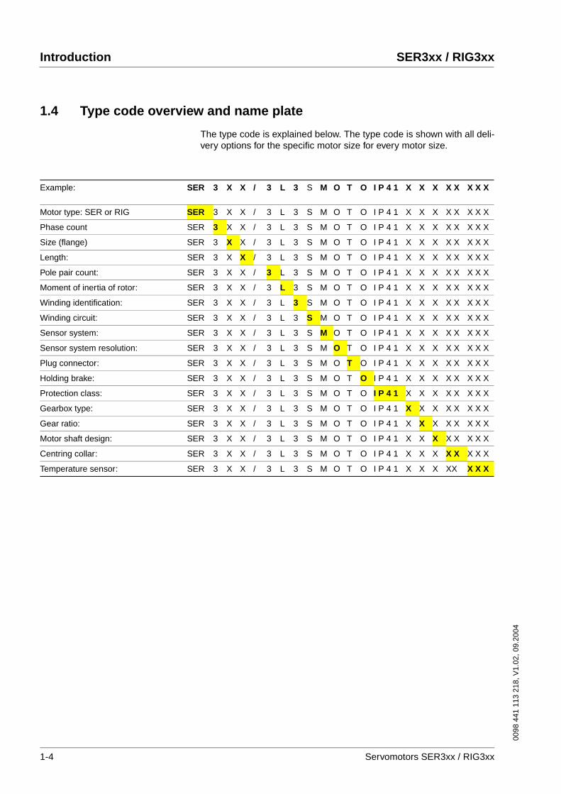
1.4 Type code overview and name plate
The type code is explained below. The type code is shown with all deli-very options for the specific motor size for every motor size.
Example: SER 3 X X / 3 L 3 S M O T O I P 4 1 X X X X X X X X
Motor type: SER or RIG SER 3 X X / 3 L 3 S M O T O I P 4 1 X X X X X X X X
Phase count SER 3 X X / 3 L 3 S M O T O I P 4 1 X X X X X X X X
Size (flange) SER 3 X X / 3 L 3 S M O T O I P 4 1 X X X X X X X X
Length: SER 3 X X / 3 L 3 S M O T O I P 4 1 X X X X X X X X
Pole pair count: SER 3 X X / 3 L 3 S M O T O I P 4 1 X X X X X X X X
Moment of inertia of rotor: SER 3 X X / 3 L 3 S M O T O I P 4 1 X X X X X X X X
Winding identification: SER 3 X X / 3 L 3 S M O T O I P 4 1 X X X X X X X X
Winding circuit: SER 3 X X / 3 L 3 S M O T O I P 4 1 X X X X X X X X
Sensor system: SER 3 X X / 3 L 3 S M O T O I P 4 1 X X X X X X X X
Sensor system resolution: SER 3 X X / 3 L 3 S M O T O I P 4 1 X X X X X X X X
Plug connector: SER 3 X X / 3 L 3 S M O T O I P 4 1 X X X X X X X X
Holding brake: SER 3 X X / 3 L 3 S M O T O I P 4 1 X X X X X X X X
Protection class: SER 3 X X / 3 L 3 S M O T O I P 4 1 X X X X X X X X
Gearbox type: SER 3 X X / 3 L 3 S M O T O I P 4 1 X X X X X X X X
Gear ratio: SER 3 X X / 3 L 3 S M O T O I P 4 1 X X X X X X X X
Motor shaft design: SER 3 X X / 3 L 3 S M O T O I P 4 1 X X X X X X X X
Centring collar: SER 3 X X / 3 L 3 S M O T O I P 4 1 X X X X X X X X
Temperature sensor: SER 3 X X / 3 L 3 S M O T O I P 4 1 X X X XX X X X
1-4 Servomotors SER3xx / RIG3xx
0098
441
113
218
, V1.
02, 0
9.20
04
SER3xx / RIG3xx Introduction
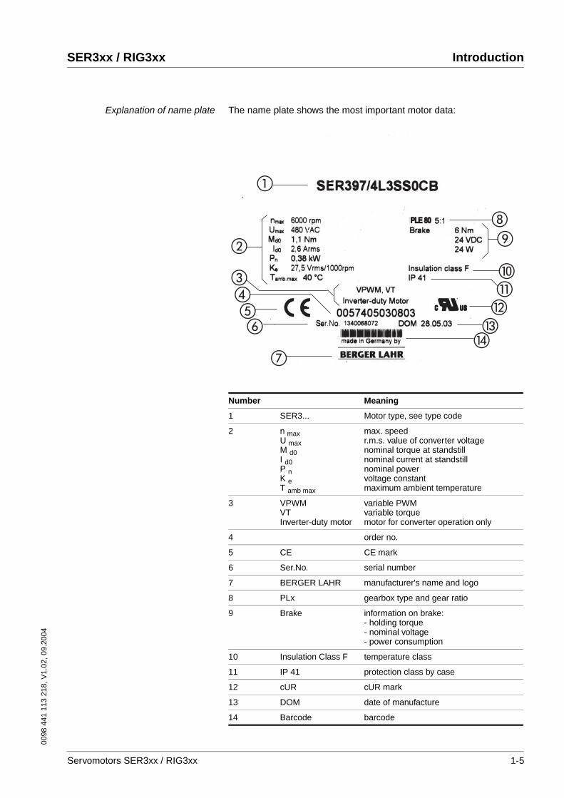
Explanation of name plate The name plate shows the most important motor data:
�
�
����
�
�
�
�
�
PLE 80PLE 80
Number Meaning
1 SER3... Motor type, see type code
2 n maxU maxM d0I d0P nK eT amb max
max. speedr.m.s. value of converter voltagenominal torque at standstillnominal current at standstillnominal powervoltage constantmaximum ambient temperature
3 VPWMVTInverter-duty motor
variable PWMvariable torquemotor for converter operation only
4 order no.
5 CE CE mark
6 Ser.No. serial number
7 BERGER LAHR manufacturer's name and logo
8 PLx gearbox type and gear ratio
9 Brake information on brake: - holding torque- nominal voltage- power consumption
10 Insulation Class F temperature class
11 IP 41 protection class by case
12 cUR cUR mark
13 DOM date of manufacture
14 Barcode barcode
Servomotors SER3xx / RIG3xx 1-5
Introduction SER3xx / RIG3xx
0098
441
113
218
, V1.
02, 0
9.20
04
1.5 Directives and standards
The EC directives define the minimum requirements - particularly safety requirements - applicable to a product and must be complied with by all manufacturers and dealers marketing the product in the member states of the European Union (EU).
The EC directives describe the main requirements for a product. The technical details are laid down in the harmonized standards, which are published in Germany as the DIN EN standards. If there is not yet any EN standard applicable to a particular product area, existing technical standards and regulations will apply.
CE mark With the declaration of conformity and the CE mark on the product the manufacturer certifies that the product complies with the requirements of all relevant EC directives. The drive systems described here can be used anywhere in the world.
EC Machine Directive The drive systems described here are not machines as defined by the EC Machine Directive (89/392/EEC) but components for installation in machines. They do not have moving parts designed for specific purpo-ses. However, they can be components of a machine or system.
The manufacturer must certify that the complete system conforms to the machine directive with the CE mark.
EC EMC Directive The EC Electromagnetic Compatibility Directives (89/336/EEC) applies to products that cause electromagnetic interference or whose operation may be be adversely affected by electromagnetic interference.
Conformity with the EMC Directive can only be expected of our drive systems after correct installation in the machine. The information on ensuring electromagnetic compatibility given in the chapter on "Installa-tion" must be followed to ensure that the drive system in the machine or system is EMC-compatible and that the product can legally be operated.
EC Low-Voltage Directive The EC Low-Voltage Directive (73/23/EEC) lays down safety require-ments for 'electrical apparatus' as protection against the risks that can originate in such devices and can be created in response to external in-fluences.
The drive systems described here comply with the EN 50178 Standard as per the Low-Voltage Directive.
Standards for safe operation of ourdrive systems
DIN 332-2: Centre hole, 60° with thread
DIN 6885: Parallel keys, grooves
DIN 42955: Concentricity of shaft ends
DIN EN 50178: Fitting power systems with electronic equipment
DIN EN 50347: Centring diameter, hole circle, fastening screws
DIN EN 60034-ff: Rotating electrical machines
DIN EN 60068-2-ff: Environmental tests
DIN EN 60664: Insulation coordination
UL1004: Motor classification under UL
1-6 Servomotors SER3xx / RIG3xx

0098
441
113
218
, V1.
02, 0
9.20
04
SER3xx / RIG3xx Introduction
1.6 Declaration of conformity
EC Declaration of Conformity
Year 2004 BERGER LAHR GmbH & Co.KG
Breslauer Str. 7
D-77933 Lahr
according to EC Directive on Machinery 98/37/EEC
according to EC Directive EMC 89/336/EEC
according to EC Directive Low Voltage 73/23/EEC
The above mentioned directives have been changed by CE Marking Directive 93/68/EEC
We declare that the products listed below meet the requirements of the mentioned EC
Directives with respect to design, construction and version distributed by us. This declaration
becomes invalid with any modification on the products not authorized by us.
Designation: 3 Phase Servo Motor with/without integrated gear
Type: SER3xxx/xL, RIG3xx/4L
Product number: 0x54xxxxxxxxx, 0x55xxxxxxxxx, 0x56xxxxxxxxx, 0x57xxxxxxxxx
0x58xxxxxxxxx
Applied
harmonized
standards,
especially:
EN 60034-1:2000 Temperature class F
EN 60034-5:2001 Protection class according product documentation
EN 60664-1:2003 Insulation
EN 60664-3:2003 Insulation
Applied
national standards
and technical
specifications,
especially:
UL 1004
the valid product documentation
Company stamp:
Date/ Signature: 16 February 2004
Name/ Department: Wolfgang Brandstätter/R & D
Servomotors SER3xx / RIG3xx 1-7

Introduction SER3xx / RIG3xx
0098
441
113
218
, V1.
02, 0
9.20
04
1-8 Servomotors SER3xx / RIG3xx

0098
441
113
218
, V1.
02, 0
9.20
04
SER3xx / RIG3xx Safety
2 Safety
2.1 Qualification of personnel
Commissioning, operation and maintenance must be conducted by trai-ned electrical and controller technicians only.
The technicians must be familiar with the contents of all technical docu-mentation relevant to this product.
The technicians must have sufficient training, knowledge and experi-ence to recognise and avoid dangers.
The technicians must be familiar with the relevant standards, regulations and safety regulations that must be observed during installation, opera-tion and maintenance of the product.
2.2 Intended use
The drive systems described here are products for general use that con-form to the state of the art in technology and are designed to prevent any dangers. However, drives and drive controllers that are not specifically designed for safety functions are not approved for applications where the functioning of the drive could endanger persons. The possibility of unexpected or unbraked movements can never be totally excluded wit-hout additional safety equipment. For this reason personnel must never be in the danger zone of the drives unless additional suitable safety equipment prevents any personal danger. This applies to operation of the machine during production and also to all service and maintenance work on drives and the machine. The machine design must ensure per-sonal safety. Suitable measures for prevention of property damage are also required.
In the system configuration described the drive systems must be used in industrial applications only and must have a fixed connection only.
In all cases the applicable safety regulations and the specified operating conditions, such as environmental conditions and specified technical data, must be observed.
The drive systems may be commissioned and operated only after instal-lation in accordance with EMC requirements and the product-specific specifications.
To prevent personal injury and damage to property damaged drive sys-tems must not be installed or operated.
Changes and modifications of the drive systems are not permitted and if made all no warranty and liability will be accepted.
The drive system must be operated only with the specified wiring and approved accessories. In general, use only original accessories and spare parts.
The drive systems must not be operated in an environment subject to explosion hazard (ex area).
Servomotors SER3xx / RIG3xx 2-1

Safety SER3xx / RIG3xx
0098
441
113
218
, V1.
02, 0
9.20
04
2.3 Hazard categories
Safety notes and general information are indicated by hazard messages in the manual. In addition there are symbols and instructions affixed to the product that warn of possible hazards and help to operate the pro-duct safely.
Depending on the seriousness of the hazard, the messages are divided into three hazard categories.
DANGER!DANGER indicates an imminently hazardous situation, which, if not avoided, will result in death, serious injury, or equipment damage.
WARNING!WARNING indicates a potentially hazardous situation, which, if not avoided, can result in death, serious injury, or equipment damage.
CAUTION!CAUTION indicates a potentially hazardous situation, which, if not avoided, can result in injury or equipment damage.
2-2 Servomotors SER3xx / RIG3xx
0098
441
113
218
, V1.
02, 0
9.20
04
SER3xx / RIG3xx Safety
2.4 Safety instructions
DANGER!Electric shock, fire or explosion
• Only technicians who are familiar with and understand the con-tents of this manual and the other relevant manuals are authori-sed to work on and with this drive system.
• Before working on the drive system:
– Switch off power to all terminals.
– Place a sign "DO NOT SWITCH ON" on the switch and lock to prevent its being switched on.
– Allow the DC bus capacitors to discharge (see power ampli-fier manual).
– Check that there is no power.
• Do not short-circuit DC bus or touch unshielded components or screws of the terminals under voltage.
• Install all covers and close the housing doors before applying power.
• The motor generates voltage when the shaft is rotated. Lock the shaft of the motor to prevent rotation before starting work on the drive system.
• AC voltages may jump over unused wires in the motor cable. Isolate unused wires at both ends of the motor cable.
• The system manufacturer is responsible for compliance with all applicable regulations relevant to earthing the drive system. Extend the earth through the motor cable with an additional earth at the motor housing.
Failure to follow these instructions will result in death or serious injury.
Servomotors SER3xx / RIG3xx 2-3
Safety SER3xx / RIG3xx
0098
441
113
218
, V1.
02, 0
9.20
04
2-4 Servomotors SER3xx / RIG3xx
0098
441
113
218
, V1.
02, 0
9.20
04
SER3xx / RIG3xx Technical Data
3 Technical Data
The following pages contain information on our SER3xx and RIG3xx motor families and an overview of gearboxes.
3.1 SER3xx
3.1.1 SER3xx general
The motors of the SER3xx series are 6-pole or 8-pole AC synchronous servomotors.
They are distinguished by:
• high power density
• integrated thermal winding monitoring
• insulation test voltage in accordance with DIN EN 60034-1 (IEC 60034-1)
• temperature class F in accordance with DIN EN 60034-1 (IEC 60034-1)
• vibration grade R in accordance with DIN EN 60034-14 (IEC 60034-14)
• shaft eccentricity and axial precision in accordance with DIN 42955 N (IEC 60072-1)
• colour: black RAL 9005
Environmental influences: ambientoperating climate
Environmental influences: ambientclimate for transport and storage
The motors must be in a dry, dust-free and vibration-free environment during transport and storage. The storage and transport temperature must remain in the range given below; in case of doubt the storage area must be air-conditioned.
The storage period is primarily determined by the durability of the lubri-cants in the warehouses and should be less than 36 months. Occasional operation of the drive solution is recommended to ensure that it still ope-rates.
Temperature (t) -20°C to +40°C
Humidity 75%rh annual average
95%rh on 30 days (non-condensing)
Storage and transport temperature -25°C to +70°C
Servomotors SER3xx / RIG3xx 3-1
Technical Data SER3xx / RIG3xx
0098
441
113
218
, V1.
02, 0
9.20
04
Service life The service life of the motors when operated correctly is limited primarily by the bearing life.
The following operating conditions can in some cases significantly re-duce the service life:
• Installation altitude above 1000 m over sea level
• Rotary movement exclusively within a fixed angle of 100°
• Operation under vibration stress greater than 20 m/s2
• Allowing sealing rings to run dry
• Wetting gaskets with aggressive media
Maximum angular acceleration The maximum angular acceleration must not exceed 200000 rad/sec2 for motors of the SER3x series.
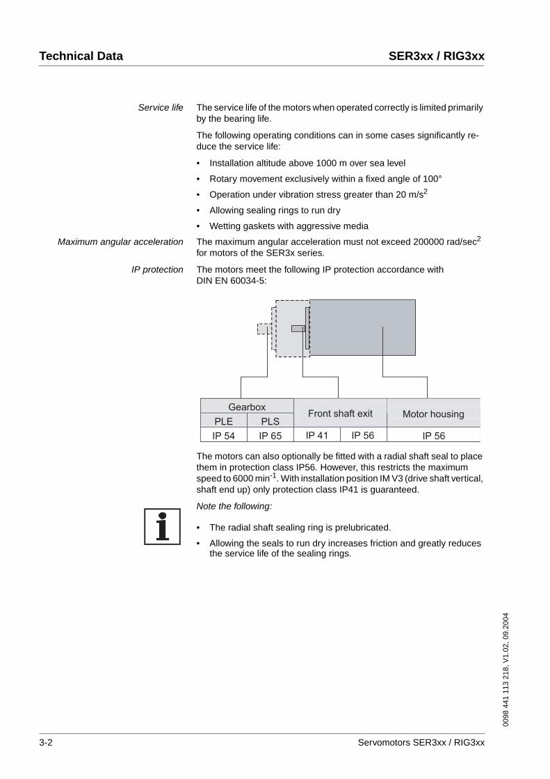
IP protection The motors meet the following IP protection accordance with DIN EN 60034-5:
The motors can also optionally be fitted with a radial shaft seal to place them in protection class IP56. However, this restricts the maximum speed to 6000 min-1. With installation position IM V3 (drive shaft vertical, shaft end up) only protection class IP41 is guaranteed.
Note the following:
• The radial shaft sealing ring is prelubricated.
• Allowing the seals to run dry increases friction and greatly reduces the service life of the sealing rings.
Gearbox
PLE PLSFront shaft exit
IP 54 IP 65 IP 41 IP 56 IP 56
Motor housing
3-2 Servomotors SER3xx / RIG3xx
0098
441
113
218
, V1.
02, 0
9.20
04
SER3xx / RIG3xx Technical Data
Overview of IP protection
3.1.1.1 Position capture (sensor)
Standard position capture
SinCos (SRS50) Singleturn This sensor system measures an absolute value within one revolution after being switched on and continues to count incrementally from this point.
For more information see www.stegmann.de
Optional position capture
As an alternative to the standard sensor system the motors can also be ordered with one of the following sensor systems:
First digit Second digit
Protection against foreign bodies
Protection against water
0 no protection 0 no protection
1 foreign body > 50mm 1 vertically falling drops
2 foreign body > 12mm 2 diagonally falling drops (75°-90°)
3 foreign body > 2.5mm 3 spray water
4 foreign body > 1mm 4 splashing water
5 dust-protected 5 jet water
6 dust-proof 6 heavy sea
7 immersion
8 continuous immersion
Resolution depends on controller
Measurement range absolute 1 revolution
Error limit of the digital absolute value depending on the controller
±1.5 minutes of arc
Precision of the incremental posi-tion evaluation
±0.75 minutes of arc
Pulse shape sinus
Supply voltage 7-12V (8V recommended)
Supply current max. 80mA (without load)
Servomotors SER3xx / RIG3xx 3-3
Technical Data SER3xx / RIG3xx
0098
441
113
218
, V1.
02, 0
9.20
04
SinCos (SRM50) Multiturn This sensor system measures an absolute value within 4096 revolutions after being switched on and continues to count incrementally from this point.
For more information see www.stegmann.de
Resolver This sensor system is very robust. Absolute position capture is possible within one revolution.
Digital encoder (DiCoder) This sensor system is an optical (incremental) system. It is only available for the SER39x and SER311x motor series, it is not available for SER36x.
For more information see www.stegmann.de
Resolution depends on controller
Measurement range absolute 4096 revolutions
Error limit of the digital absolute value depending on the controller
±1.5 minutes of arc
Precision of the incremental posi-tion evaluation
±0.75 minutes of arc
Pulse shape sinus
Supply voltage 7-12V (8V recommended)
Supply current max. 80mA (without load)
Resolution depends on the controller
Measurement range absolute 1 revolution
Precision of the incremental posi-tion evaluation
±6 minutes of arc
Input voltage 7Veff
Input current max. 38mA
Resolution 1024 and 4096 bars/revolution
Measurement range absolute 1 revolution
Precision ±2 minutes of arc
Signals A, B, C, commutation
Pulse shape rectangular
Supply voltage 5V ± 10%
Supply current max. 50mA (without load)
3-4 Servomotors SER3xx / RIG3xx
0098
441
113
218
, V1.
02, 0
9.20
04
SER3xx / RIG3xx Technical Data
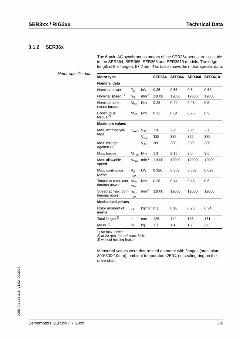
3.1.2 SER36x
The 6-pole AC synchronous motors of the SER36x series are available in the SER364, SER366, SER368 and SER3610 models. The edge length of the flange is 57.2 mm. The table shows the motor-specific data:
Motor-specific data
Measured values were determined on motor with flanges (steel plate 300*300*10mm); ambient temperature 25°C; no sealing ring on the drive shaft
Motor type SER364 SER366 SER368 SER3610
Nominal data
Nominal power PN kW 0.35 0.55 0.6 0.63
Nominal speed 1)
1) for max. power
nN min-1 12000 12000 12000 12000
Nominal conti-nuous torque
MdN Nm 0.28 0.44 0.48 0.5
Continuous torque 2)
2) at 20 rpm; for n=0 max. 89%
Md0 Nm 0.32 0.54 0.75 0.9
Maximum values
Max. winding vol-tage
Umax VAC 230 230 230 230
VDC 325 325 325 325
Max. voltage against PE
VAC 300 300 300 300
Max. torque Mmax Nm 1.3 2.15 3.0 3.6
Max. allowable speed
nmax min-1 12000 12000 12000 12000
Max. continuous power
Pdmax
kW 0.326 0.553 0.603 0.628
Torque at max. con-tinuous power
MPd-max
Nm 0.28 0.44 0.48 0.5
Speed at max. con-tinuous power
nPd-max
min-1 12000 12000 12000 12000
Mechanical values
Rotor moment of inertia
JR kgcm2 0.1 0.18 0.26 0.34
Total length 3)
3) without holding brake
L mm 126 144 163 181
Mass 3) m kg 1.1 1.4 1.7 2.0
Servomotors SER3xx / RIG3xx 3-5
Technical Data SER3xx / RIG3xx
0098
441
113
218
, V1.
02, 0
9.20
04
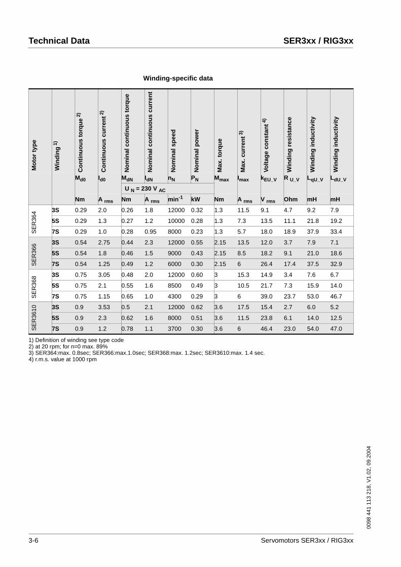
Winding-specific data
Mo
tor
typ
e
Win
din
g1)
Co
nti
nu
ou
s to
rqu
e2)
Co
nti
nu
ou
s cu
rren
t2)
No
min
al c
on
tin
uo
us
torq
ue
No
min
al c
on
tin
uo
us
curr
ent
No
min
al s
pee
d
No
min
al p
ow
er
Max
. to
rqu
e
Max
. cu
rren
t3)
Volt
age
con
stan
t4)
Win
din
g r
esis
tan
ce
Win
din
g in
du
ctiv
ity
Win
din
g in
du
ctiv
ity
Md0 Id0 MdN IdN nN PN Mmax Imax kEU_V R U_V LqU_V LdU_V
U N = 230 V AC
Nm A rms Nm A rms min-1 kW Nm A rms V rms Ohm mH mH
SE
R36
4 3S 0.29 2.0 0.26 1.8 12000 0.32 1.3 11.5 9.1 4.7 9.2 7.9
5S 0.29 1.3 0.27 1.2 10000 0.28 1.3 7.3 13.5 11.1 21.8 19.2
7S 0.29 1.0 0.28 0.95 8000 0.23 1.3 5.7 18.0 18.9 37.9 33.4
SE
R36
6 3S 0.54 2.75 0.44 2.3 12000 0.55 2.15 13.5 12.0 3.7 7.9 7.1
5S 0.54 1.8 0.46 1.5 9000 0.43 2.15 8.5 18.2 9.1 21.0 18.6
7S 0.54 1.25 0.49 1.2 6000 0.30 2.15 6 26.4 17.4 37.5 32.9
SE
R36
8 3S 0.75 3.05 0.48 2.0 12000 0.60 3 15.3 14.9 3.4 7.6 6.7
5S 0.75 2.1 0.55 1.6 8500 0.49 3 10.5 21.7 7.3 15.9 14.0
7S 0.75 1.15 0.65 1.0 4300 0.29 3 6 39.0 23.7 53.0 46.7
SE
R36
10 3S 0.9 3.53 0.5 2.1 12000 0.62 3.6 17.5 15.4 2.7 6.0 5.2
5S 0.9 2.3 0.62 1.6 8000 0.51 3.6 11.5 23.8 6.1 14.0 12.5
7S 0.9 1.2 0.78 1.1 3700 0.30 3.6 6 46.4 23.0 54.0 47.0
1) Definition of winding see type code2) at 20 rpm; for n=0 max. 89%3) SER364:max. 0.8sec; SER366:max.1.0sec; SER368:max. 1.2sec; SER3610:max. 1.4 sec.4) r.m.s. value at 1000 rpm
3-6 Servomotors SER3xx / RIG3xx

0098
441
113
218
, V1.
02, 0
9.20
04
SER3xx / RIG3xx Technical Data
Torque characteristic SER364
1 Peak motor torque1.1 Speed limit at 230Veff2 Continuous torque of motor
SER364/3L3S
0
0,2
0,4
0,6
0,8
1
1,2
1,4
0 2000 4000 6000 8000 10000 12000
n [rpm]
M[Nm]
1 1.1
2
SER364/3L5S
0
0,2
0,4
0,6
0,8
1
1,2
1,4
0 2000 4000 6000 8000 10000 12000
n [rpm]
M[Nm]
1
1.1
2
SER364/3L7S
0
0,2
0,4
0,6
0,8
1
1,2
1,4
0 2000 4000 6000 8000 10000 12000
n [rpm]
M[Nm]
1
1.1
2
Servomotors SER3xx / RIG3xx 3-7
Technical Data SER3xx / RIG3xx
0098
441
113
218
, V1.
02, 0
9.20
04
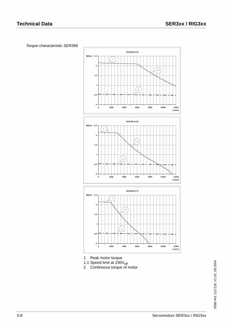
Torque characteristic SER366
1 Peak motor torque1.1 Speed limit at 230Veff2 Continuous torque of motor
SER366/3L3S
0
0,5
1
1,5
2
2,5
0 2000 4000 6000 8000 10000 12000
n [rpm]
M[Nm]
1
1.1
2
SER366/3L5S
0
0,5
1
1,5
2
2,5
0 2000 4000 6000 8000 10000 12000
n [rpm]
M[Nm]
2
1
1.1
SER366/3L7S
0
0,5
1
1,5
2
2,5
0 2000 4000 6000 8000 10000 12000
n [rpm]
M[Nm]
1
1.1
2
3-8 Servomotors SER3xx / RIG3xx
0098
441
113
218
, V1.
02, 0
9.20
04
SER3xx / RIG3xx Technical Data
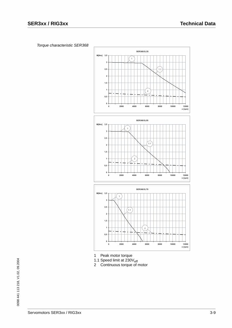
Torque characteristic SER368
1 Peak motor torque1.1 Speed limit at 230Veff2 Continuous torque of motor
SER368/3L3S
0
0,5
1
1,5
2
2,5
3
3,5
0 2000 4000 6000 8000 10000 12000
n [rpm]
M[Nm]
1
1.1
2
SER368/3L5S
0
0,5
1
1,5
2
2,5
3
3,5
0 2000 4000 6000 8000 10000 12000
n [rpm]
M[Nm]
1
2
1.1
SER368/3L7S
0
0,5
1
1,5
2
2,5
3
3,5
0 2000 4000 6000 8000 10000 12000
n [rpm]
M[Nm]
1
1.1
2
Servomotors SER3xx / RIG3xx 3-9
Technical Data SER3xx / RIG3xx
0098
441
113
218
, V1.
02, 0
9.20
04
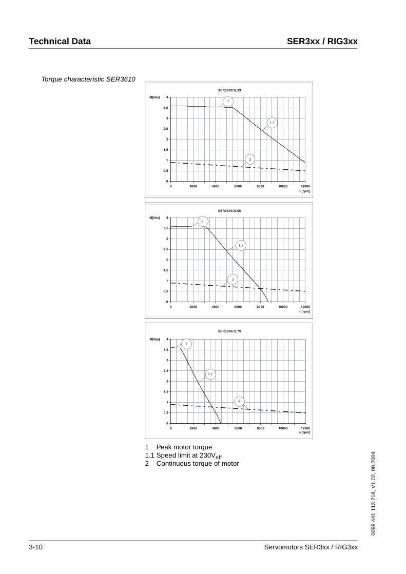
Torque characteristic SER3610
1 Peak motor torque1.1 Speed limit at 230Veff2 Continuous torque of motor
SER3610/3L3S
0
0,5
1
1,5
2
2,5
3
3,5
4
0 2000 4000 6000 8000 10000 12000
n [rpm]
M[Nm]1
1.1
2
SER3610/3L5S
0
0,5
1
1,5
2
2,5
3
3,5
4
0 2000 4000 6000 8000 10000 12000
n [rpm]
M[Nm]
1.1
1
2
SER3610/3L7S
0
0,5
1
1,5
2
2,5
3
3,5
4
0 2000 4000 6000 8000 10000 12000
n [rpm]
M[Nm]
1
1.1
2
3-10 Servomotors SER3xx / RIG3xx
0098
441
113
218
, V1.
02, 0
9.20
04
SER3xx / RIG3xx Technical Data
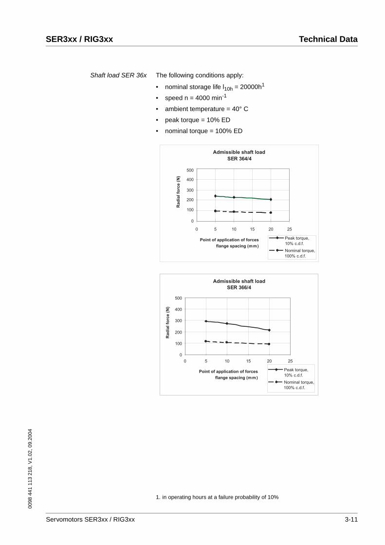
Shaft load SER 36x The following conditions apply:
• nominal storage life l10h = 20000h1
• speed n = 4000 min-1
• ambient temperature = 40° C
• peak torque = 10% ED
• nominal torque = 100% ED
1. in operating hours at a failure probability of 10%
SER 364/4
0
100
200
300
400
500
0 5 10 15 20 25
Admissible shaft load
Point of application of forces
flange spacing (mm)
Rad
ial fo
rce (
N)
Nominal torque,
100% c.d.f.
Peak torque,
10% c.d.f.
SER 366/4
0
100
200
300
400
500
0 5 10 15 20 25
Admissible shaft load
Point of application of forces
flange spacing (mm)
Rad
ial fo
rce (
N)
Nominal torque,
100% c.d.f.
Peak torque,
10% c.d.f.
Servomotors SER3xx / RIG3xx 3-11
Technical Data SER3xx / RIG3xx
0098
441
113
218
, V1.
02, 0
9.20
04
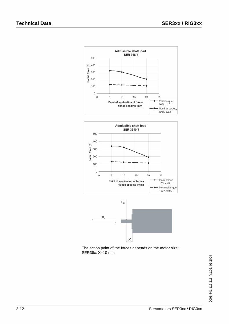
The action point of the forces depends on the motor size:SER36x: X=10 mm
SER 368/4
0
100
200
300
400
500
0 5 10 15 20 25
Admissible shaft load
Point of application of forces
flange spacing (mm)
Rad
ial fo
rce (
N)
Nominal torque,
100% c.d.f.
Peak torque,
10% c.d.f.
Admissible shaft load
SER 3610/4
0
100
200
300
400
500
0 5 10 15 20 25
Point of application of forces
flange spacing (mm)
Rad
ial fo
rce (
N)
Nominal torque,
100% c.d.f.
Peak torque,
10% c.d.f.
X
FA
FR
3-12 Servomotors SER3xx / RIG3xx
0098
441
113
218
, V1.
02, 0
9.20
04
SER3xx / RIG3xx Technical Data
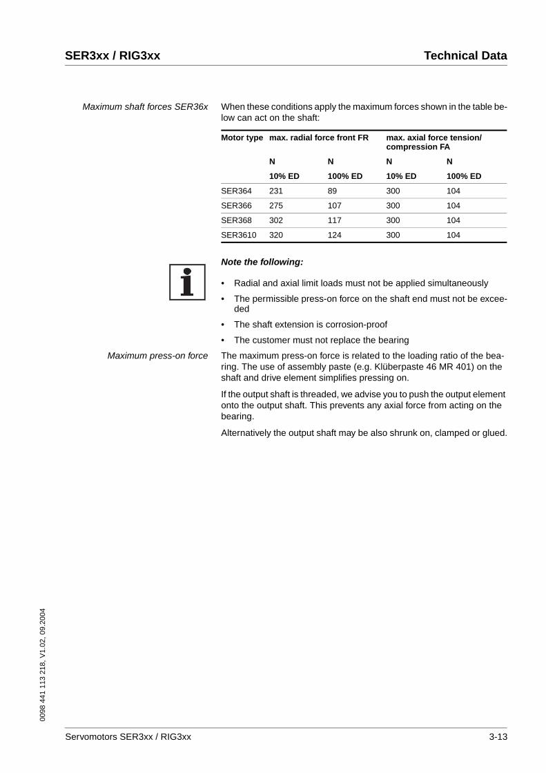
Maximum shaft forces SER36x When these conditions apply the maximum forces shown in the table be-low can act on the shaft:
Note the following:
• Radial and axial limit loads must not be applied simultaneously
• The permissible press-on force on the shaft end must not be excee-ded
• The shaft extension is corrosion-proof
• The customer must not replace the bearing
Maximum press-on force The maximum press-on force is related to the loading ratio of the bea-ring. The use of assembly paste (e.g. Klüberpaste 46 MR 401) on the shaft and drive element simplifies pressing on.
If the output shaft is threaded, we advise you to push the output element onto the output shaft. This prevents any axial force from acting on the bearing.
Alternatively the output shaft may be also shrunk on, clamped or glued.
Motor type max. radial force front FR max. axial force tension/compression FA
N N N N
10% ED 100% ED 10% ED 100% ED
SER364 231 89 300 104
SER366 275 107 300 104
SER368 302 117 300 104
SER3610 320 124 300 104
Servomotors SER3xx / RIG3xx 3-13
Technical Data SER3xx / RIG3xx
0098
441
113
218
, V1.
02, 0
9.20
04
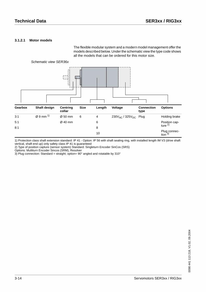
3.1.2.1 Motor models
The flexible modular system and a modern model management offer the models described below. Under the schematic view the type code shows all the models that can be ordered for this motor size.
Schematic view SER36x
Gearbox Shaft design Centring collar
Size Length Voltage Connectiontype
Options
3:1
5:1
8:1
Ø 9 mm 1) Ø 50 mm
Ø 40 mm
6 4
6
8
10
230VAC / 325VDC Plug Holding brake
Position cap-ture 2)
Plug connec-tion 3)
1) Protection class shaft extension standard: IP 41 - Option: IP 56 with shaft sealing ring, with installed length IM V3 (drive shaft vertical, shaft end up) only safety class IP 41 is guaranteed2) Type of position capture (sensor system) Standard: Singleturn Encoder SinCos (SRS)Options: Multiturn Encoder Sincos (SRM), Resolver3) Plug connection: Standard = straight; option= 90° angled and rotatable by 310°
3-14 Servomotors SER3xx / RIG3xx
0098
441
113
218
, V1.
02, 0
9.20
04
SER3xx / RIG3xx Technical Data
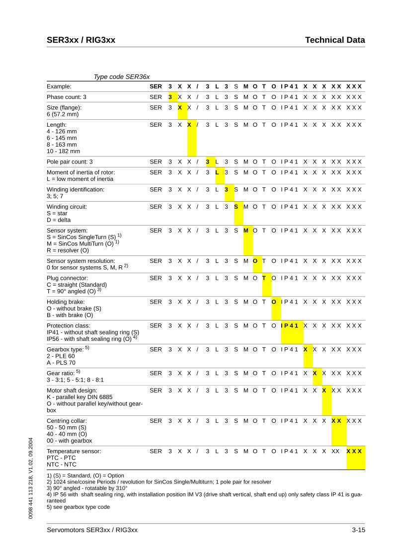
Type code SER36xExample: SER 3 X X / 3 L 3 S M O T O I P 4 1 X X X X X X X X
Phase count: 3 SER 3 X X / 3 L 3 S M O T O I P 4 1 X X X X X X X X
Size (flange):6 (57.2 mm)
SER 3 X X / 3 L 3 S M O T O I P 4 1 X X X X X X X X
Length:4 - 126 mm6 - 145 mm8 - 163 mm10 - 182 mm
SER 3 X X / 3 L 3 S M O T O I P 4 1 X X X X X X X X
Pole pair count: 3 SER 3 X X / 3 L 3 S M O T O I P 4 1 X X X X X X X X
Moment of inertia of rotor:L = low moment of inertia
SER 3 X X / 3 L 3 S M O T O I P 4 1 X X X X X X X X
Winding identification:3; 5; 7
SER 3 X X / 3 L 3 S M O T O I P 4 1 X X X X X X X X
Winding circuit:S = starD = delta
SER 3 X X / 3 L 3 S M O T O I P 4 1 X X X X X X X X
Sensor system:S = SinCos SingleTurn (S) 1)
M = SinCos MultiTurn (O) 1)
R = resolver (O)
SER 3 X X / 3 L 3 S M O T O I P 4 1 X X X X X X X X
Sensor system resolution:0 for sensor systems S, M, R 2)
SER 3 X X / 3 L 3 S M O T O I P 4 1 X X X X X X X X
Plug connector:C = straight (Standard)T = 90° angled (O) 3)
SER 3 X X / 3 L 3 S M O T O I P 4 1 X X X X X X X X
Holding brake: O - without brake (S)B - with brake (O)
SER 3 X X / 3 L 3 S M O T O I P 4 1 X X X X X X X X
Protection class:IP41 - without shaft sealing ring (S)IP56 - with shaft sealing ring (O) 4)
SER 3 X X / 3 L 3 S M O T O I P 4 1 X X X X X X X X
Gearbox type: 5)
2 - PLE 60A - PLS 70
SER 3 X X / 3 L 3 S M O T O I P 4 1 X X X X X X X X
Gear ratio: 5)
3 - 3:1; 5 - 5:1; 8 - 8:1SER 3 X X / 3 L 3 S M O T O I P 4 1 X X X X X X X X
Motor shaft design:K - parallel key DIN 6885O - without parallel key/without gear-box
SER 3 X X / 3 L 3 S M O T O I P 4 1 X X X X X X X X
Centring collar:50 - 50 mm (S)40 - 40 mm (O)00 - with gearbox
SER 3 X X / 3 L 3 S M O T O I P 4 1 X X X X X X X X
Temperature sensor:PTC - PTCNTC - NTC
SER 3 X X / 3 L 3 S M O T O I P 4 1 X X X XX X X X
1) (S) = Standard, (O) = Option2) 1024 sine/cosine Periods / revolution for SinCos Single/Multiturn; 1 pole pair for resolver3) 90° angled - rotatable by 310°4) IP 56 with shaft sealing ring, with installation position IM V3 (drive shaft vertical, shaft end up) only safety class IP 41 is gua-ranteed5) see gearbox type code
Servomotors SER3xx / RIG3xx 3-15

Technical Data SER3xx / RIG3xx
0098
441
113
218
, V1.
02, 0
9.20
04
3.1.2.2 Dimensional drawing
Dimensions SER36x
3.1.2.3 Options
Holding brake
Holding brake SER36x The holding brake is an electromagnetic spring-pressure brake. It holds the motor axis after the motor current is switched off, including after po-wer failure and EMERGENCY STOP. A holding brake is required parti-cularly for torque loads caused by weight forces, such as occur with Z-axes in handling technology. The control is described in Chapter 4.3.2 “Electrical control of the holding brake“.
L
5.55.5
Ø9
j69
j6
2020
ØD
-0.0
5D
-0.0
5
57.257.2
47.1447.14
1.61.6 Ø5.25.2
Ø76.876.8
3434
21.621.63131
5252
3939
4444
4
DIN 332 - DS M3
Motor8 pol
(DiCoder 17 pol)
Encoder12 pol
fix
optionca. 100˚
ca. 210˚option
ca. 100˚option
option ca. 210˚
Feather key A3x3x12 DIN 6885
SER
36X
XSE
R 36
XX
SER 364 SER 366 SER 368 SER 3610
L (length without brake) [mm] 126 144 163 181
L (length with brake) [mm] 166 184 203 221
WARNING!Loss of braking power by wear.
Incorrect use of the holding brake causes accelerated wear and loss of braking power.
• Do not use the brake as a service brake.Failure to follow these instructions can result in death or serious injury.
Technical Data
Nominal voltage [DC] 24 V ±10%
Holding torque 1.2 Nm
Electrical pick-up power 10 W
Moment of inertia 0.07 kgcm2
Make time (brake ventilation) 14 ms
Break time (close brake) 13 ms
Mass approx. 0.3 kg
3-16 Servomotors SER3xx / RIG3xx

0098
441
113
218
, V1.
02, 0
9.20
04
SER3xx / RIG3xx Technical Data
Position capture
SinCos Multiturn sensor system(SRM50)
This sensor system measures an absolute value within 4096 revolutions after being switched on and continues to count incrementally from this point.
Resolver sensor system This sensor system is a very robust absolute system. Absolute position capture is possible within one revolution.
The data for the sensor systems can be found in Chapter 3.1.1.1 “Posi-tion capture (sensor)“.
Gearbox
Gearbox in general Our servomotors can be combined with the standard gearboxes for your application. The following tables show our motor and gearbox combina-tions.
The listed measured values were determined by continuous output of the maximum torque through the gearbox in your application (maximum acceleration and shortest cycle times to maximum torque).
Under normal operation peak torques cannot be output continuously wi-thout thermal overload of the motor. If the gearbox is selected in accor-dance with the specified values, it will remain in the safe range.
If the motors are not used in the maximum torque range, other gearbo-xes can be selected in accordance with our combination options.
If you have any special requirements in addition to the standard range, please contact our technical support.
The values in bold in the table indicate that the torque is restricted by the gearbox or motor. Uneconomical combinations are indicated with x; the gearbox is overdimensioned or underdimensioned. The index "G" refers to the gearbox output shaft.
CAUTION!The gearbox can be destroyed by overload.
Exceeding the allowable torques will cause accelerated wear, shaft breakage or blocking.
• Do not exceed the peak gearbox torque in any operating status.
• Limit the motor torque if there is a danger of destruction of the gearbox by peak torques.
• Limit the torque in short-time operation (e.g. in an EMER-GENCY STOP situation) to twice the continuous gearbox out-put torque MdG
Failure to follow these instructions can result in injury or equipment damage.
Servomotors SER3xx / RIG3xx 3-17

Technical Data SER3xx / RIG3xx
0098
441
113
218
, V1.
02, 0
9.20
04
Gearbox type PLE Economical precision planetary gearbox
For more information on the gearboxes see Chapter 3.3 “PLE and PLS gearbox“.
Gearbox type PLS High-quality low-play planetary gearbox
A PLS 70 gearbox can be attached for greater precision. With the gear ratio 8:1 at high torques it is an economical alternative.
For more information on the gearboxes see Chapter 3.3 “PLE and PLS gearbox“.
M d0 Motor Gearbox 3:1 3:1 3:1 5:1 5:1 5:1 8:1 8:1 8:1
M d0 Nm
M d0G1)
NmM dG
2) Nm
M maxG3)
NmM d0G
1) Nm
M dG2)
NmM maxG
3) Nm
M d0G1)
NmM dG
2) Nm
M maxG3)
Nm
0,32 SER364 PLE 60 0,96 12 3,9 1,6 16 6,5 2,56 15 10,4
054 SER366 PLE 60 1,62 12 6,45 2,7 16 10,75 4,32 15 17,2
0,75 SER368 PLE 60 2,25 12 9 3,75 16 15 6 15 24
0,9 SER3610 PLE 60 2,7 12 10,8 4,5 16 18 7,2 15 28,8
1) Md0G Nominal torque at low speed = guide value for selection of the gearbox2) MdG Gearbox output torque (continuous torque)3) MmaxG Max. output torque with this motor - (theoretical value, calculated from max. motor torque Mmax *ratio)
3-18 Servomotors SER3xx / RIG3xx
0098
441
113
218
, V1.
02, 0
9.20
04
SER3xx / RIG3xx Technical Data
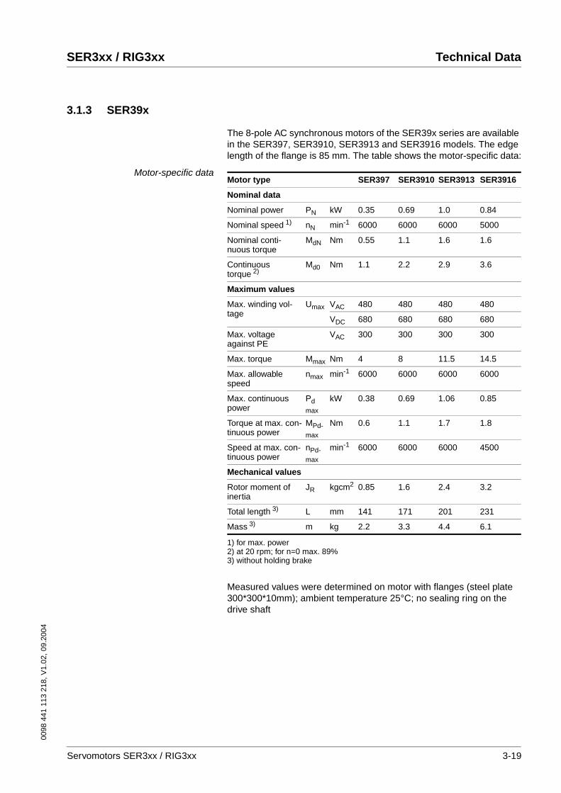
3.1.3 SER39x
The 8-pole AC synchronous motors of the SER39x series are available in the SER397, SER3910, SER3913 and SER3916 models. The edge length of the flange is 85 mm. The table shows the motor-specific data:
Motor-specific data
Measured values were determined on motor with flanges (steel plate 300*300*10mm); ambient temperature 25°C; no sealing ring on the drive shaft
Motor type SER397 SER3910 SER3913 SER3916
Nominal data
Nominal power PN kW 0.35 0.69 1.0 0.84
Nominal speed 1)
1) for max. power
nN min-1 6000 6000 6000 5000
Nominal conti-nuous torque
MdN Nm 0.55 1.1 1.6 1.6
Continuous torque 2)
2) at 20 rpm; for n=0 max. 89%
Md0 Nm 1.1 2.2 2.9 3.6
Maximum values
Max. winding vol-tage
Umax VAC 480 480 480 480
VDC 680 680 680 680
Max. voltage against PE
VAC 300 300 300 300
Max. torque Mmax Nm 4 8 11.5 14.5
Max. allowable speed
nmax min-1 6000 6000 6000 6000
Max. continuous power
Pdmax
kW 0.38 0.69 1.06 0.85
Torque at max. con-tinuous power
MPd-max
Nm 0.6 1.1 1.7 1.8
Speed at max. con-tinuous power
nPd-max
min-1 6000 6000 6000 4500
Mechanical values
Rotor moment of inertia
JR kgcm2 0.85 1.6 2.4 3.2
Total length 3)
3) without holding brake
L mm 141 171 201 231
Mass 3) m kg 2.2 3.3 4.4 6.1
Servomotors SER3xx / RIG3xx 3-19

Technical Data SER3xx / RIG3xx
0098
441
113
218
, V1.
02, 0
9.20
04
Winding-specific data
Mo
tor
typ
e
Win
din
g1)
Co
nti
nu
ou
s to
rqu
e2)
Co
nti
nu
ou
s cu
rren
t2)
No
min
al c
on
tin
uo
us
torq
ue
No
min
al c
on
tin
uo
us
curr
ent
No
min
al s
pee
d
No
min
al p
ow
er
No
min
al c
on
tin
uo
us
torq
ue
No
min
al c
on
tin
uo
us
curr
ent
No
min
al s
pee
d
No
min
al p
ow
er
No
min
al c
on
tin
uo
us
torq
ue
No
min
al c
on
tin
uo
us
curr
ent
No
min
al s
pee
d
No
min
al p
ow
er
Max
. to
rqu
e
Max
. cu
rren
t3)
Volt
age
con
stan
t4)
Win
din
g r
esis
tan
ce
Win
din
g in
du
ctiv
ity
Win
din
g in
du
ctiv
ity
Md
0
I d0
Md
N
I dN
nN
PN
Md
N
I dN
nN
PN
Md
N
I dN
nN
PN
Mm
ax
I max
k EU
_V
R U
_V
Lq
U_V
Ld
U_V
U N = 230 V AC U N = 400 V AC U N = 480 V AC
Nm
A rm
s
Nm
A rm
s
min
-1
kW Nm
A rm
s
min
-1
kW Nm
A rm
s
min
-1
kW Nm
A rm
s
V rm
s
Oh
m
mH
mH
SE
R39
7 3S 1.1 2.6 0.6 1.5 6000 0.38 0.6 1.5 6000 0.38 0.6 1.5 6000 0.38 4.0 12.0 27.5 3.7 13.6 11.7
7S 1.1 1.3 0.8 1.0 3600 0.30 0.6 0.7 6000 0.38 0.6 0.7 6000 0.38 4.0 6.0 50.7 13 47.9 40.9
SE
R39
10 3S 2.2 3.0 1.6 2.1 4000 0.67 1.1 1.8 6000 0.69 1.1 1.8 6000 0.69 8.0 13.5 47.2 5.4 20.3 17.6
7S 2.2 1.7 1.8 1.4 2200 0.42 1.5 1.2 4000 0.63 1.3 1.1 4700 0.64 8.0 8.0 83.2 13.7 60.7 51.5
SE
R39
13 3S 2.9 3.7 2.1 2.9 3800 0.84 1.7 2.5 6000 1.06 1.7 2.5 6000 1.06 11.5 18.0 49.5 3.3 14.1 12.2
5S 2.9 2.5 2.5 2.1 2500 0.65 2.0 1.8 4500 0.94 1.8 1.6 5500 1.04 11.5 12.0 72.3 7.5 30.3 26.1
7S 2.9 1.3 2.6 1.2 1200 0.33 2.5 1.1 2300 0.60 2.4 1.1 2600 0.65 11.5 6.0 141.6 27.5 115 98.6
SE
R39
13 3S 3.6 4.4 1.9 2.5 4000 0.80 1.1 1.7 6000 0.69 1.1 1.7 6000 0.69 14.5 22.0 51.5 2.65 10.2 8.4
5S 3.6 3.5 2.3 2.3 3000 0.72 1.6 1.9 5000 0.84 1.1 1.1 6000 0.69 14.5 17.5 65.0 4.2 18.6 15.8
7S 3.6 2.1 2.8 1.8 1800 0.53 2.2 1.5 3300 0.76 2 1.2 3800 0.80 14.5 10.5 103.6 10.4 51.8 41.4
1) Definition of winding see type code2) at 20 rpm; for n=0 max. 89%3) max. 2.5 sec.4) r.m.s. value at 1000 rpm
3-20 Servomotors SER3xx / RIG3xx
0098
441
113
218
, V1.
02, 0
9.20
04
SER3xx / RIG3xx Technical Data
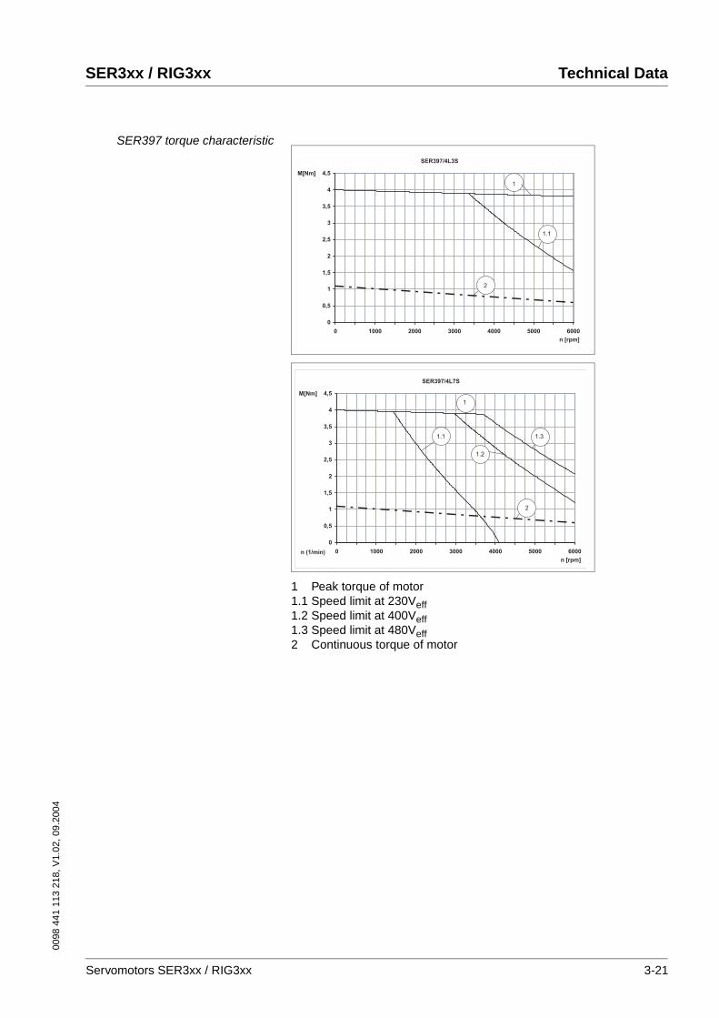
SER397 torque characteristic
1 Peak torque of motor1.1 Speed limit at 230Veff1.2 Speed limit at 400Veff1.3 Speed limit at 480Veff2 Continuous torque of motor
SER397/4L3S
0
0,5
1
1,5
2
2,5
3
3,5
4
4,5
0 1000 2000 3000 4000 5000 6000
n [rpm]
M[Nm]
1
1.1
2
SER397/4L7S
0
0,5
1
1,5
2
2,5
3
3,5
4
4,5
0 1000 2000 3000 4000 5000 6000n (1/min)
n [rpm]
1.2
M[Nm]
1
1.1 1.3
2
Servomotors SER3xx / RIG3xx 3-21
Technical Data SER3xx / RIG3xx
0098
441
113
218
, V1.
02, 0
9.20
04
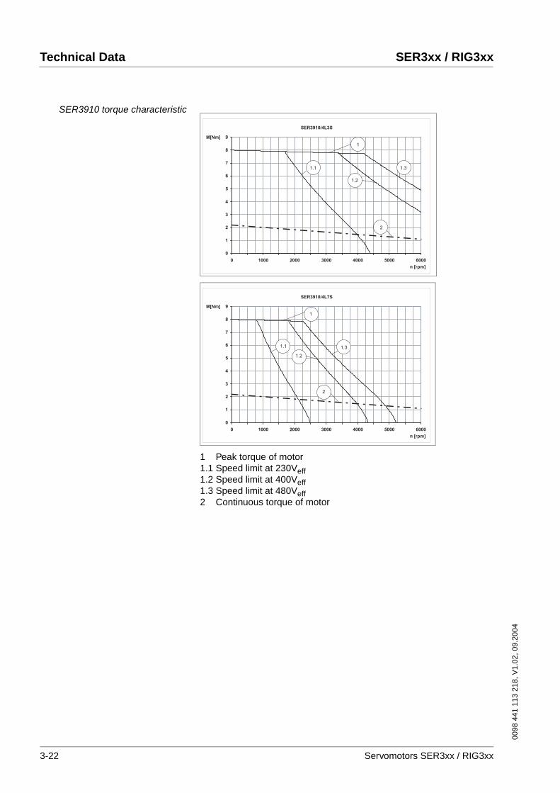
SER3910 torque characteristic
1 Peak torque of motor1.1 Speed limit at 230Veff1.2 Speed limit at 400Veff1.3 Speed limit at 480Veff2 Continuous torque of motor
SER3910/4L3S
0
1
2
3
4
5
6
7
8
9
0 1000 2000 3000 4000 5000 6000
n [rpm]
M[Nm]
1
1.1
1.2
1.3
2
SER3910/4L7S
0
1
2
3
4
5
6
7
8
9
0 1000 2000 3000 4000 5000 6000
n [rpm]
M[Nm]
1
1.1
1.2
1.3
2
3-22 Servomotors SER3xx / RIG3xx
0098
441
113
218
, V1.
02, 0
9.20
04
SER3xx / RIG3xx Technical Data
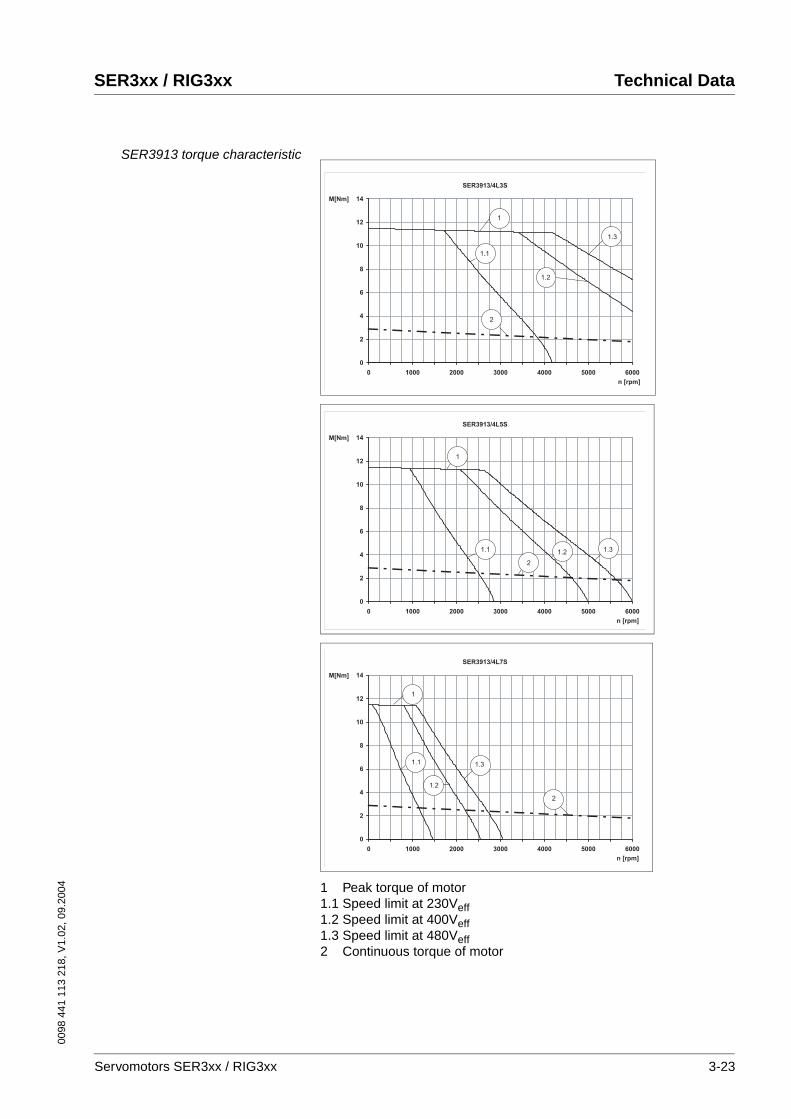
SER3913 torque characteristic
1 Peak torque of motor1.1 Speed limit at 230Veff1.2 Speed limit at 400Veff1.3 Speed limit at 480Veff2 Continuous torque of motor
SER3913/4L3S
0
2
4
6
8
10
12
14
0 1000 2000 3000 4000 5000 6000
n [rpm]
M[Nm]
1
1.1
1.2
1.3
2
SER3913/4L5S
0
2
4
6
8
10
12
14
0 1000 2000 3000 4000 5000 6000
n [rpm]
M[Nm]
1.1 1.2 1.3
1
2
SER3913/4L7S
0
2
4
6
8
10
12
14
0 1000 2000 3000 4000 5000 6000
n [rpm]
M[Nm]
1
1.1
1.2
1.3
2
Servomotors SER3xx / RIG3xx 3-23
Technical Data SER3xx / RIG3xx
0098
441
113
218
, V1.
02, 0
9.20
04
SER3916 torque characteristic
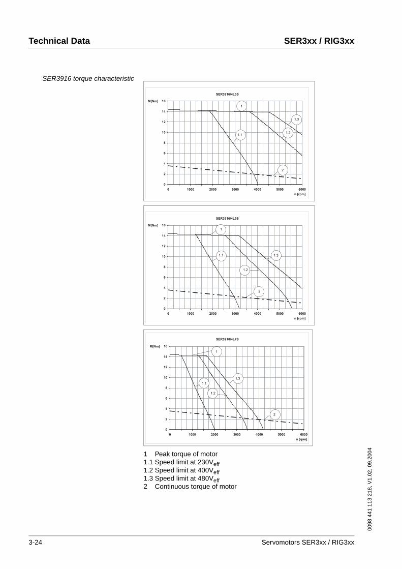
1 Peak torque of motor1.1 Speed limit at 230Veff1.2 Speed limit at 400Veff1.3 Speed limit at 480Veff2 Continuous torque of motor
SER3916/4L3S
0
2
4
6
8
10
12
14
16
0 1000 2000 3000 4000 5000 6000
n [rpm]
M[Nm]
1
2
1.11.2
1.3
SER3916/4L5S
0
2
4
6
8
10
12
14
16
0 1000 2000 3000 4000 5000 6000
n [rpm]
M[Nm]
1
2
1.1 1.3
1.2
SER3916/4L7S
0
2
4
6
8
10
12
14
16
0 1000 2000 3000 4000 5000 6000
n [rpm]
M[Nm]
1
2
1.1
1.2
1.3
3-24 Servomotors SER3xx / RIG3xx
0098
441
113
218
, V1.
02, 0
9.20
04
SER3xx / RIG3xx Technical Data
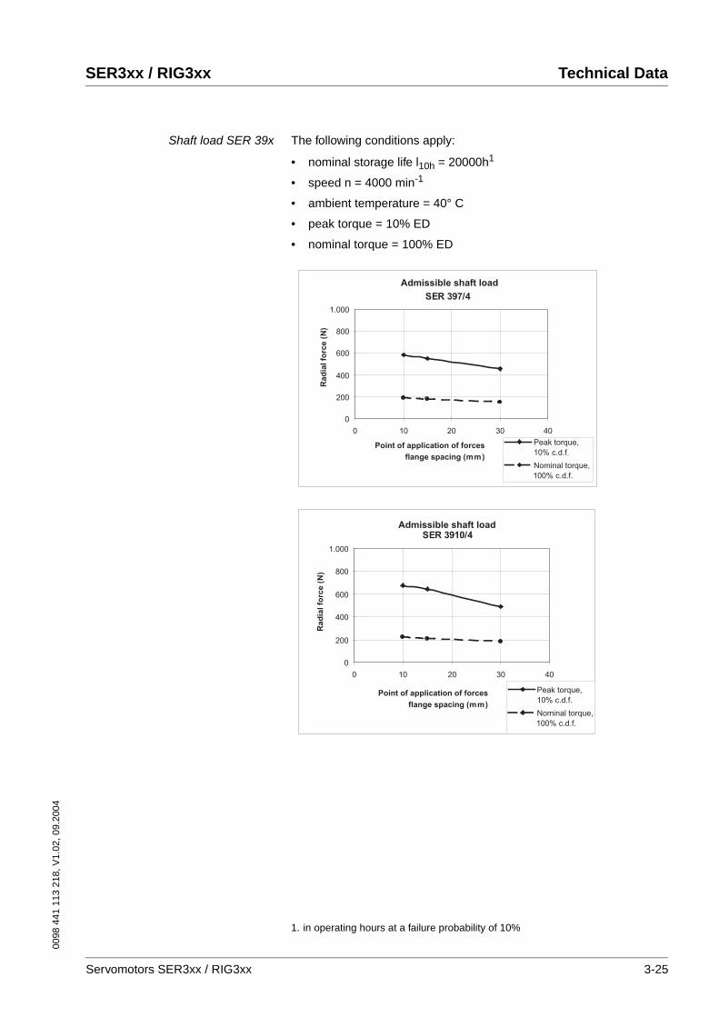
Shaft load SER 39x The following conditions apply:
• nominal storage life l10h = 20000h1
• speed n = 4000 min-1
• ambient temperature = 40° C
• peak torque = 10% ED
• nominal torque = 100% ED
1. in operating hours at a failure probability of 10%
SER 397/4
0
200
400
600
800
1.000
0 10 20 30 40
Admissible shaft load
Point of application of forces
flange spacing (mm)
Rad
ial fo
rce (
N)
Nominal torque,
100% c.d.f.
Peak torque,
10% c.d.f.
SER 3910/4
0
200
400
600
800
1.000
0 10 20 30 40
Admissible shaft load
Point of application of forces
flange spacing (mm)
Rad
ial fo
rce (
N)
Nominal torque,
100% c.d.f.
Peak torque,
10% c.d.f.
Servomotors SER3xx / RIG3xx 3-25
Technical Data SER3xx / RIG3xx
0098
441
113
218
, V1.
02, 0
9.20
04
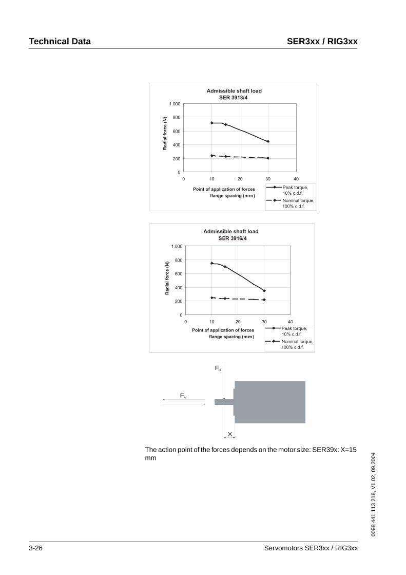
The action point of the forces depends on the motor size: SER39x: X=15 mm
SER 3913/4
0
200
400
600
800
1.000
0 10 20 30 40
Admissible shaft load
Point of application of forces
flange spacing (mm)
Rad
ial fo
rce (
N)
Nominal torque,
100% c.d.f.
Peak torque,
10% c.d.f.
SER 3916/4
0
200
400
600
800
1.000
0 10 20 30 40
Admissible shaft load
Point of application of forces
flange spacing (mm)
Rad
ial fo
rce (
N)
Nominal torque,
100% c.d.f.
Peak torque,
10% c.d.f.
X
FA
FR
3-26 Servomotors SER3xx / RIG3xx
0098
441
113
218
, V1.
02, 0
9.20
04
SER3xx / RIG3xx Technical Data
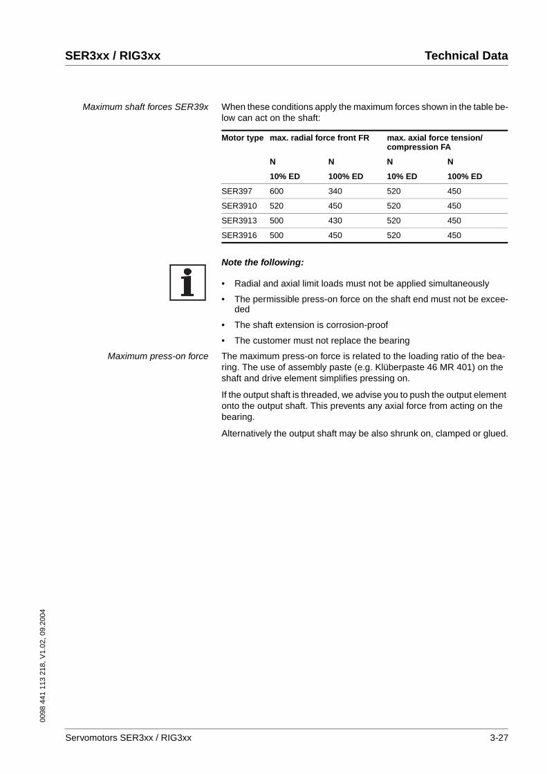
Maximum shaft forces SER39x When these conditions apply the maximum forces shown in the table be-low can act on the shaft:
Note the following:
• Radial and axial limit loads must not be applied simultaneously
• The permissible press-on force on the shaft end must not be excee-ded
• The shaft extension is corrosion-proof
• The customer must not replace the bearing
Maximum press-on force The maximum press-on force is related to the loading ratio of the bea-ring. The use of assembly paste (e.g. Klüberpaste 46 MR 401) on the shaft and drive element simplifies pressing on.
If the output shaft is threaded, we advise you to push the output element onto the output shaft. This prevents any axial force from acting on the bearing.
Alternatively the output shaft may be also shrunk on, clamped or glued.
Motor type max. radial force front FR max. axial force tension/compression FA
N N N N
10% ED 100% ED 10% ED 100% ED
SER397 600 340 520 450
SER3910 520 450 520 450
SER3913 500 430 520 450
SER3916 500 450 520 450
Servomotors SER3xx / RIG3xx 3-27
Technical Data SER3xx / RIG3xx
0098
441
113
218
, V1.
02, 0
9.20
04
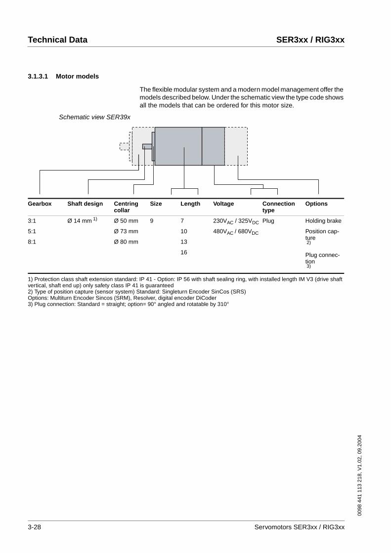
3.1.3.1 Motor models
The flexible modular system and a modern model management offer the models described below. Under the schematic view the type code shows all the models that can be ordered for this motor size.
Schematic view SER39x
Gearbox Shaft design Centring collar
Size Length Voltage Connectiontype
Options
3:1
5:1
8:1
Ø 14 mm 1) Ø 50 mm
Ø 73 mm
Ø 80 mm
9 7
10
13
16
230VAC / 325VDC
480VAC / 680VDC
Plug Holding brake
Position cap-ture2)
Plug connec-tion3)
1) Protection class shaft extension standard: IP 41 - Option: IP 56 with shaft sealing ring, with installed length IM V3 (drive shaft vertical, shaft end up) only safety class IP 41 is guaranteed2) Type of position capture (sensor system) Standard: Singleturn Encoder SinCos (SRS)Options: Multiturn Encoder Sincos (SRM), Resolver, digital encoder DiCoder3) Plug connection: Standard = straight; option= 90° angled and rotatable by 310°
3-28 Servomotors SER3xx / RIG3xx
0098
441
113
218
, V1.
02, 0
9.20
04
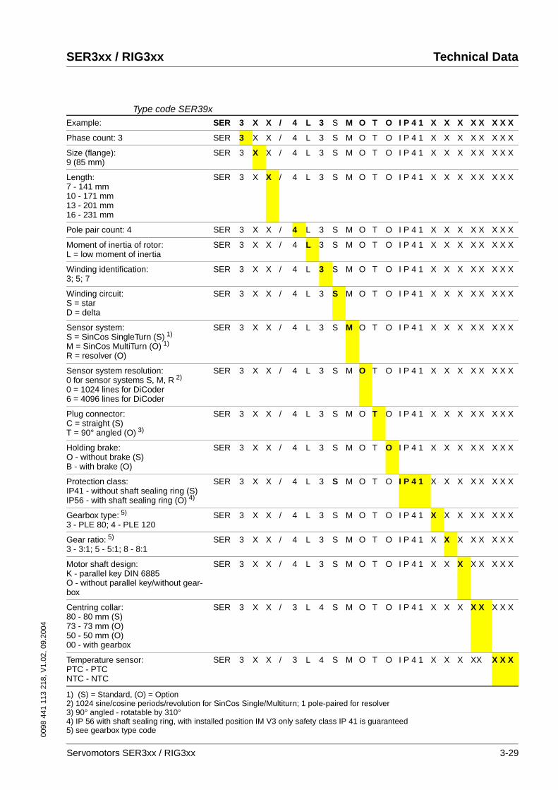
SER3xx / RIG3xx Technical Data
Type code SER39xExample: SER 3 X X / 4 L 3 S M O T O I P 4 1 X X X X X X X X
Phase count: 3 SER 3 X X / 4 L 3 S M O T O I P 4 1 X X X X X X X X
Size (flange):9 (85 mm)
SER 3 X X / 4 L 3 S M O T O I P 4 1 X X X X X X X X
Length:7 - 141 mm10 - 171 mm13 - 201 mm16 - 231 mm
SER 3 X X / 4 L 3 S M O T O I P 4 1 X X X X X X X X
Pole pair count: 4 SER 3 X X / 4 L 3 S M O T O I P 4 1 X X X X X X X X
Moment of inertia of rotor:L = low moment of inertia
SER 3 X X / 4 L 3 S M O T O I P 4 1 X X X X X X X X
Winding identification:3; 5; 7
SER 3 X X / 4 L 3 S M O T O I P 4 1 X X X X X X X X
Winding circuit:S = starD = delta
SER 3 X X / 4 L 3 S M O T O I P 4 1 X X X X X X X X
Sensor system:S = SinCos SingleTurn (S) 1)
M = SinCos MultiTurn (O) 1)
R = resolver (O)
SER 3 X X / 4 L 3 S M O T O I P 4 1 X X X X X X X X
Sensor system resolution:0 for sensor systems S, M, R 2)
0 = 1024 lines for DiCoder6 = 4096 lines for DiCoder
SER 3 X X / 4 L 3 S M O T O I P 4 1 X X X X X X X X
Plug connector:C = straight (S)T = 90° angled (O) 3)
SER 3 X X / 4 L 3 S M O T O I P 4 1 X X X X X X X X
Holding brake:O - without brake (S)B - with brake (O)
SER 3 X X / 4 L 3 S M O T O I P 4 1 X X X X X X X X
Protection class:IP41 - without shaft sealing ring (S)IP56 - with shaft sealing ring (O) 4)
SER 3 X X / 4 L 3 S M O T O I P 4 1 X X X X X X X X
Gearbox type: 5)
3 - PLE 80; 4 - PLE 120 SER 3 X X / 4 L 3 S M O T O I P 4 1 X X X X X X X X
Gear ratio: 5)
3 - 3:1; 5 - 5:1; 8 - 8:1SER 3 X X / 4 L 3 S M O T O I P 4 1 X X X X X X X X
Motor shaft design:K - parallel key DIN 6885O - without parallel key/without gear-box
SER 3 X X / 4 L 3 S M O T O I P 4 1 X X X X X X X X
Centring collar:80 - 80 mm (S)73 - 73 mm (O)50 - 50 mm (O)00 - with gearbox
SER 3 X X / 3 L 4 S M O T O I P 4 1 X X X X X X X X
Temperature sensor:PTC - PTCNTC - NTC
SER 3 X X / 3 L 4 S M O T O I P 4 1 X X X XX X X X
1) (S) = Standard, (O) = Option2) 1024 sine/cosine periods/revolution for SinCos Single/Multiturn; 1 pole-paired for resolver3) 90° angled - rotatable by 310°4) IP 56 with shaft sealing ring, with installed position IM V3 only safety class IP 41 is guaranteed5) see gearbox type code
Servomotors SER3xx / RIG3xx 3-29
Technical Data SER3xx / RIG3xx
0098
441
113
218
, V1.
02, 0
9.20
04
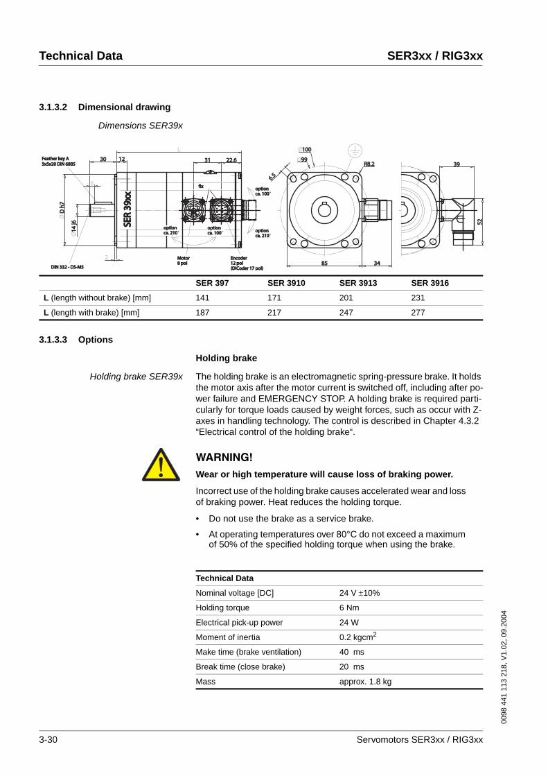
3.1.3.2 Dimensional drawing
Dimensions SER39x
3.1.3.3 Options
Holding brake
Holding brake SER39x The holding brake is an electromagnetic spring-pressure brake. It holds the motor axis after the motor current is switched off, including after po-wer failure and EMERGENCY STOP. A holding brake is required parti-cularly for torque loads caused by weight forces, such as occur with Z-axes in handling technology. The control is described in Chapter 4.3.2 “Electrical control of the holding brake“.
22.622.63131
L
12123030
2
Ø14
j614
j6
Ø D
h7
D h
7
Ø100100
Ø9999
6.56.5
R8.2R8.2
8585 3434
3939
5252
5
DIN 332 - DS-M5DIN 332 - DS-M5
EncoderEncoder12 pol12 pol
Motor Motor 8 pol 8 pol
(DiCoder 17 pol)(DiCoder 17 pol)
option option ca. 100ca. 100˚
ca. 210ca. 210˚option option ca. 100ca. 100˚
option option ca. 210ca. 210˚option option
fixfix
Feather key AFeather key A5x5x20 DIN 68855x5x20 DIN 6885
SER
39xx
SER
39xx
SER 397 SER 3910 SER 3913 SER 3916
L (length without brake) [mm] 141 171 201 231
L (length with brake) [mm] 187 217 247 277
WARNING!Wear or high temperature will cause loss of braking power.
Incorrect use of the holding brake causes accelerated wear and loss of braking power. Heat reduces the holding torque.
• Do not use the brake as a service brake.
• At operating temperatures over 80°C do not exceed a maximum of 50% of the specified holding torque when using the brake.
Failure to follow these instructions can result in death or serious injury.
Technical Data
Nominal voltage [DC] 24 V ±10%
Holding torque 6 Nm
Electrical pick-up power 24 W
Moment of inertia 0.2 kgcm2
Make time (brake ventilation) 40 ms
Break time (close brake) 20 ms
Mass approx. 1.8 kg
3-30 Servomotors SER3xx / RIG3xx

0098
441
113
218
, V1.
02, 0
9.20
04
SER3xx / RIG3xx Technical Data
Position capture
SinCos Multiturn sensor system(SRM50)
This sensor system measures an absolute value within 4096 revolutions after being switched on and continues to count incrementally from this point.
Resolver sensor system This sensor system is a very robust absolute system. Absolute position capture is possible within one revolution.
Digital encoder sensor system(DiCoder)
This sensor system is an optical (incremental) system.
The data for the sensor systems can be found in Chapter 3.1.1.1 “Posi-tion capture (sensor)“.
Gearbox
Gearbox in general Our servomotors can be combined with the standard gearboxes for your application. The following tables show our motor and gearbox combina-tions.
The listed measured values were determined by continuous output of the maximum torque through the gearbox in your application (maximum acceleration and shortest cycle times to maximum torque).
Under normal operation peak torques cannot be output continuously wi-thout thermal overload of the motor. If the gearbox is selected in accor-dance with the specified values, it will remain in the safe range.
If the motors are not used in the maximum torque range, other gearbo-xes can be selected in accordance with our combination options.
If you have any special requirements in addition to the standard range, please contact our technical support.
The values in bold in the table indicate that the torque is restricted by the gearbox or motor. Uneconomical combinations are indicated with x; the gearbox is overdimensioned or underdimensioned. The index "G" refers to the gearbox output shaft.
CAUTION!The gearbox can be destroyed by overload.
Exceeding the allowable torques will cause accelerated wear, shaft breakage or blocking.
• Do not exceed the peak gearbox torque in any operating status.
• Limit the motor torque if there is a danger of destruction of the gearbox by peak torques.
• Limit the torque in short-time operation (e.g. in an EMER-GENCY STOP situation) to twice the continuous gearbox out-put torque MdG
Failure to follow these instructions can result in injury or equipment damage.
Servomotors SER3xx / RIG3xx 3-31
Technical Data SER3xx / RIG3xx
0098
441
113
218
, V1.
02, 0
9.20
04
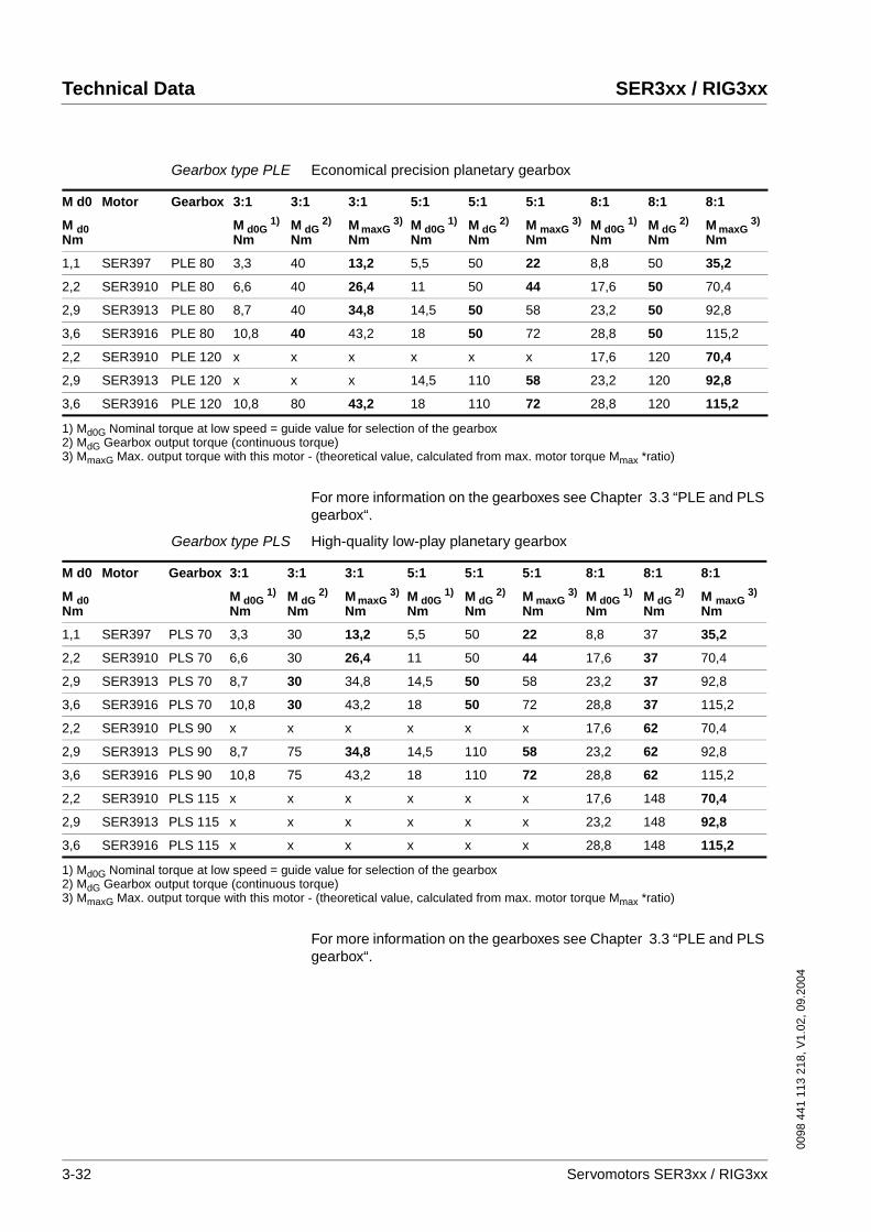
Gearbox type PLE Economical precision planetary gearbox
For more information on the gearboxes see Chapter 3.3 “PLE and PLS gearbox“.
Gearbox type PLS High-quality low-play planetary gearbox
For more information on the gearboxes see Chapter 3.3 “PLE and PLS gearbox“.
M d0 Motor Gearbox 3:1 3:1 3:1 5:1 5:1 5:1 8:1 8:1 8:1
M d0 Nm
M d0G1)
NmM dG
2) Nm
M maxG3)
NmM d0G
1) Nm
M dG2)
NmM maxG
3) Nm
M d0G1)
NmM dG
2) Nm
M maxG3)
Nm
1,1 SER397 PLE 80 3,3 40 13,2 5,5 50 22 8,8 50 35,2
2,2 SER3910 PLE 80 6,6 40 26,4 11 50 44 17,6 50 70,4
2,9 SER3913 PLE 80 8,7 40 34,8 14,5 50 58 23,2 50 92,8
3,6 SER3916 PLE 80 10,8 40 43,2 18 50 72 28,8 50 115,2
2,2 SER3910 PLE 120 x x x x x x 17,6 120 70,4
2,9 SER3913 PLE 120 x x x 14,5 110 58 23,2 120 92,8
3,6 SER3916 PLE 120 10,8 80 43,2 18 110 72 28,8 120 115,2
1) Md0G Nominal torque at low speed = guide value for selection of the gearbox2) MdG Gearbox output torque (continuous torque)3) MmaxG Max. output torque with this motor - (theoretical value, calculated from max. motor torque Mmax *ratio)
M d0 Motor Gearbox 3:1 3:1 3:1 5:1 5:1 5:1 8:1 8:1 8:1
M d0 Nm
M d0G1)
NmM dG
2) Nm
M maxG3)
NmM d0G
1) Nm
M dG2)
NmM maxG
3) Nm
M d0G1)
NmM dG
2) Nm
M maxG3)
Nm
1,1 SER397 PLS 70 3,3 30 13,2 5,5 50 22 8,8 37 35,2
2,2 SER3910 PLS 70 6,6 30 26,4 11 50 44 17,6 37 70,4
2,9 SER3913 PLS 70 8,7 30 34,8 14,5 50 58 23,2 37 92,8
3,6 SER3916 PLS 70 10,8 30 43,2 18 50 72 28,8 37 115,2
2,2 SER3910 PLS 90 x x x x x x 17,6 62 70,4
2,9 SER3913 PLS 90 8,7 75 34,8 14,5 110 58 23,2 62 92,8
3,6 SER3916 PLS 90 10,8 75 43,2 18 110 72 28,8 62 115,2
2,2 SER3910 PLS 115 x x x x x x 17,6 148 70,4
2,9 SER3913 PLS 115 x x x x x x 23,2 148 92,8
3,6 SER3916 PLS 115 x x x x x x 28,8 148 115,2
1) Md0G Nominal torque at low speed = guide value for selection of the gearbox2) MdG Gearbox output torque (continuous torque)3) MmaxG Max. output torque with this motor - (theoretical value, calculated from max. motor torque Mmax *ratio)
3-32 Servomotors SER3xx / RIG3xx
0098
441
113
218
, V1.
02, 0
9.20
04
SER3xx / RIG3xx Technical Data
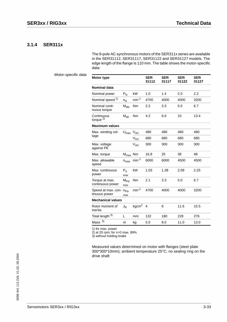
3.1.4 SER311x
The 8-pole AC synchronous motors of the SER311x series are available in the SER31112, SER31117, SER31122 and SER31127 models. The edge length of the flange is 110 mm. The table shows the motor-specific data:
Motor-specific data
Measured values determined on motor with flanges (steel plate 300*300*10mm); ambient temperature 25°C; no sealing ring on the drive shaft
Motor type SER31112
SER31117
SER31122
SER31127
Nominal data
Nominal power PN kW 1.0 1.4 2.0 2.2
Nominal speed 1)
1) for max. power
nN min-1 4700 4000 4000 3200
Nominal conti-nuous torque
MdN Nm 2.2 3.3 5.0 6.7
Continuous torque 2)
2) at 20 rpm; for n=0 max. 89%
Md0 Nm 4.2 6.6 10 13.4
Maximum values
Max. winding vol-tage
Umax VAC 480 480 480 480
VDC 680 680 680 680
Max. voltage against PE
VAC 300 300 300 300
Max. torque Mmax Nm 16.8 25 38 48
Max. allowable speed
nmax min-1 6000 6000 4500 4500
Max. continuous power
Pdmax
kW 1.03 1.38 2.09 2.25
Torque at max. continuous power
MPd-max
Nm 2.1 3.3 5.0 6.7
Speed at max. con-tinuous power
nPd-max
min-1 4700 4000 4000 3200
Mechanical values
Rotor moment of inertia
JR kgcm2 4 8 11.6 15.5
Total length 3)
3) without holding brake
L mm 132 180 228 276
Mass 3) m kg 5.0 8.0 11.0 13.0
Servomotors SER3xx / RIG3xx 3-33
Technical Data SER3xx / RIG3xx
0098
441
113
218
, V1.
02, 0
9.20
04
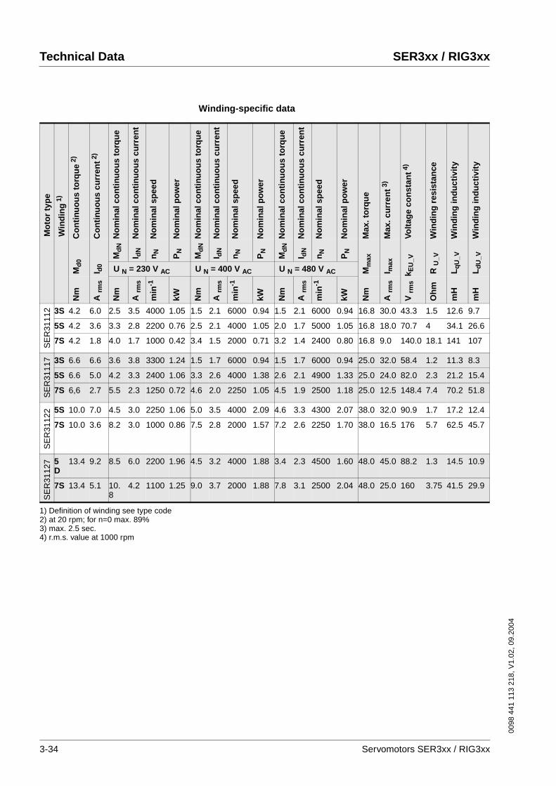
Winding-specific data
Mo
tor
typ
e
Win
din
g1)
Co
nti
nu
ou
s to
rqu
e2)
Co
nti
nu
ou
s cu
rren
t2)
No
min
al c
on
tin
uo
us
torq
ue
No
min
al c
on
tin
uo
us
curr
ent
No
min
al s
pee
d
No
min
al p
ow
er
No
min
al c
on
tin
uo
us
torq
ue
No
min
al c
on
tin
uo
us
curr
ent
No
min
al s
pee
d
No
min
al p
ow
er
No
min
al c
on
tin
uo
us
torq
ue
No
min
al c
on
tin
uo
us
curr
ent
No
min
al s
pee
d
No
min
al p
ow
er
Max
. to
rqu
e
Max
. cu
rren
t3)
Volt
age
con
stan
t4)
Win
din
g r
esis
tan
ce
Win
din
g in
du
ctiv
ity
Win
din
g in
du
ctiv
ity
Md
0
I d0
Md
N
I dN
nN
PN
Md
N
I dN
nN
PN
Md
N
I dN
nN
PN
Mm
ax
I max
k EU
_V
R U
_V
Lq
U_V
Ld
U_V
U N = 230 V AC U N = 400 V AC U N = 480 V AC
Nm
A rm
s
Nm
A rm
s
min
-1
kW Nm
A rm
s
min
-1
kW Nm
A rm
s
min
-1
kW Nm
A rm
s
V rm
s
Oh
m
mH
mH
SE
R31
112 3S 4.2 6.0 2.5 3.5 4000 1.05 1.5 2.1 6000 0.94 1.5 2.1 6000 0.94 16.8 30.0 43.3 1.5 12.6 9.7
5S 4.2 3.6 3.3 2.8 2200 0.76 2.5 2.1 4000 1.05 2.0 1.7 5000 1.05 16.8 18.0 70.7 4 34.1 26.6
7S 4.2 1.8 4.0 1.7 1000 0.42 3.4 1.5 2000 0.71 3.2 1.4 2400 0.80 16.8 9.0 140.0 18.1 141 107
SE
R31
117 3S 6.6 6.6 3.6 3.8 3300 1.24 1.5 1.7 6000 0.94 1.5 1.7 6000 0.94 25.0 32.0 58.4 1.2 11.3 8.3
5S 6.6 5.0 4.2 3.3 2400 1.06 3.3 2.6 4000 1.38 2.6 2.1 4900 1.33 25.0 24.0 82.0 2.3 21.2 15.4
7S 6,6 2.7 5.5 2.3 1250 0.72 4.6 2.0 2250 1.05 4.5 1.9 2500 1.18 25.0 12.5 148.4 7.4 70.2 51.8
SE
R31
122 5S 10.0 7.0 4.5 3.0 2250 1.06 5.0 3.5 4000 2.09 4.6 3.3 4300 2.07 38.0 32.0 90.9 1.7 17.2 12.4
7S 10.0 3.6 8.2 3.0 1000 0.86 7.5 2.8 2000 1.57 7.2 2.6 2250 1.70 38.0 16.5 176 5.7 62.5 45.7
SE
R31
127 5
D13.4 9.2 8.5 6.0 2200 1.96 4.5 3.2 4000 1.88 3.4 2.3 4500 1.60 48.0 45.0 88.2 1.3 14.5 10.9
7S 13.4 5.1 10.8
4.2 1100 1.25 9.0 3.7 2000 1.88 7.8 3.1 2500 2.04 48.0 25.0 160 3.75 41.5 29.9
1) Definition of winding see type code2) at 20 rpm; for n=0 max. 89%3) max. 2.5 sec.4) r.m.s. value at 1000 rpm
3-34 Servomotors SER3xx / RIG3xx
0098
441
113
218
, V1.
02, 0
9.20
04
SER3xx / RIG3xx Technical Data
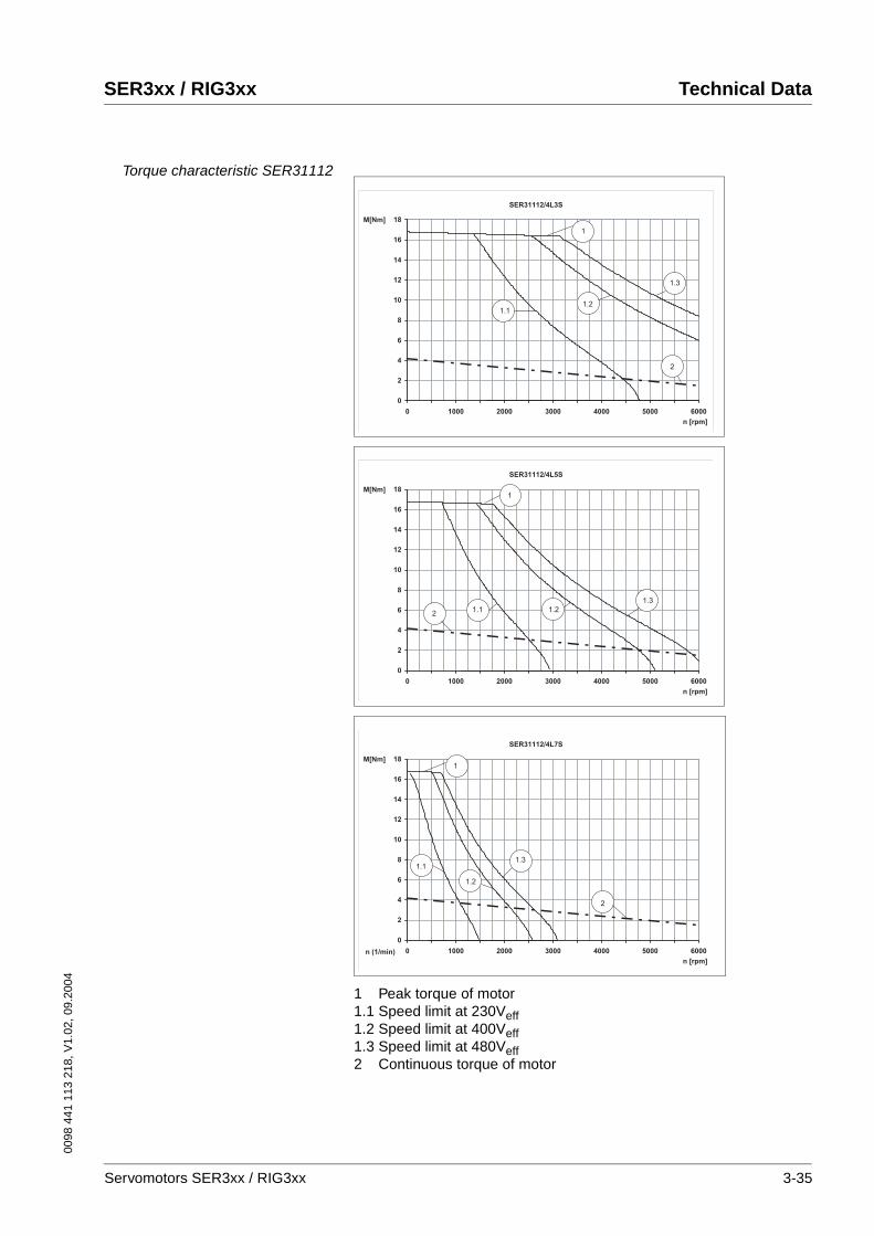
Torque characteristic SER31112
1 Peak torque of motor1.1 Speed limit at 230Veff1.2 Speed limit at 400Veff1.3 Speed limit at 480Veff2 Continuous torque of motor
SER31112/4L3S
0
2
4
6
8
10
12
14
16
18
0 1000 2000 3000 4000 5000 6000
n [rpm]
M[Nm]
1
2
1.11.2
1.3
SER31112/4L5S
0
2
4
6
8
10
12
14
16
18
0 1000 2000 3000 4000 5000 6000
n [rpm]
M[Nm]1
21.1 1.2
1.3
SER31112/4L7S
0
2
4
6
8
10
12
14
16
18
0 1000 2000 3000 4000 5000 6000n (1/min)
n [rpm]
M[Nm]1
2
1.1
1.2
1.3
Servomotors SER3xx / RIG3xx 3-35
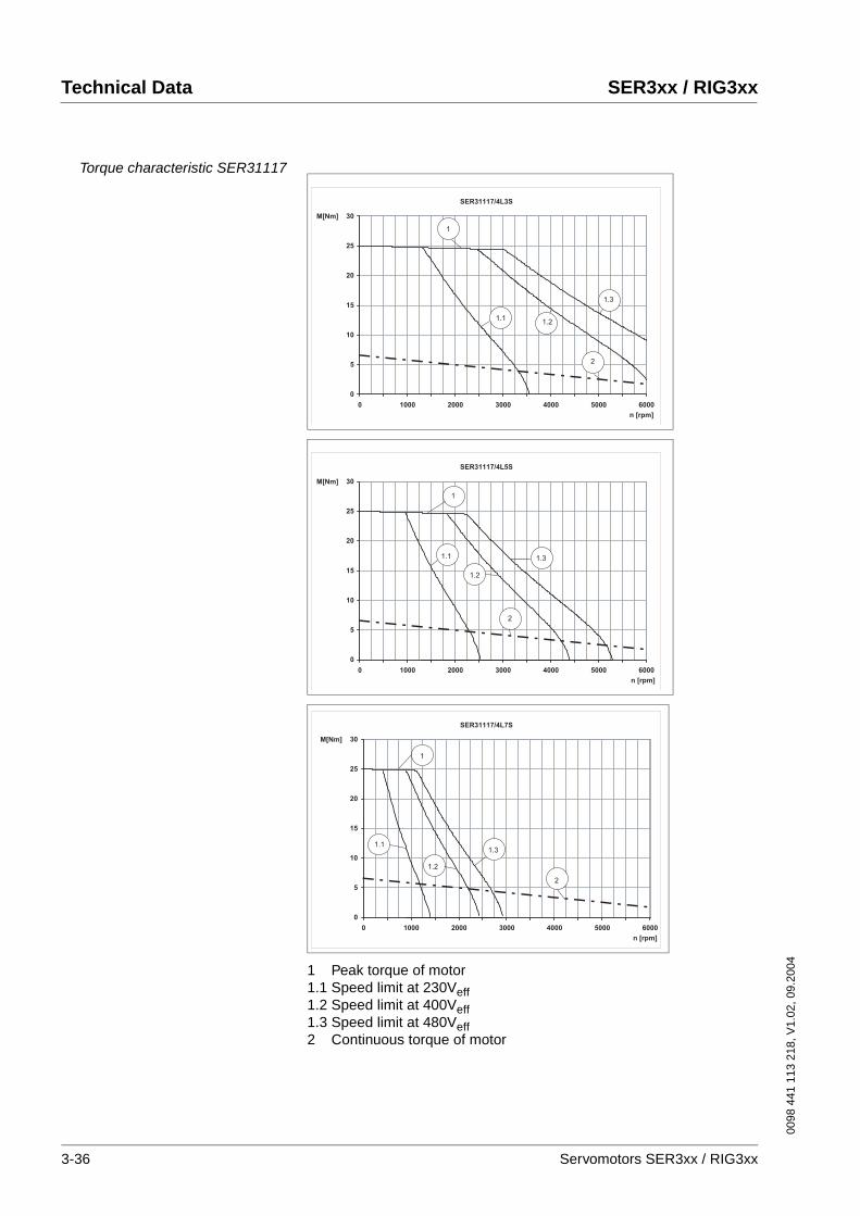
Technical Data SER3xx / RIG3xx
0098
441
113
218
, V1.
02, 0
9.20
04
Torque characteristic SER31117
1 Peak torque of motor1.1 Speed limit at 230Veff1.2 Speed limit at 400Veff1.3 Speed limit at 480Veff2 Continuous torque of motor
SER31117/4L3S
0
5
10
15
20
25
30
0 1000 2000 3000 4000 5000 6000
n [rpm]
M[Nm]
1
2
1.11.2
1.3
SER31117/4L5S
0
5
10
15
20
25
30
0 1000 2000 3000 4000 5000 6000
n [rpm]
M[Nm]
1
2
1.1 1.3
1.2
SER31117/4L7S
0
5
10
15
20
25
30
0 1000 2000 3000 4000 5000 6000
n [rpm]
M[Nm]
1
2
1.1
1.2
1.3
3-36 Servomotors SER3xx / RIG3xx
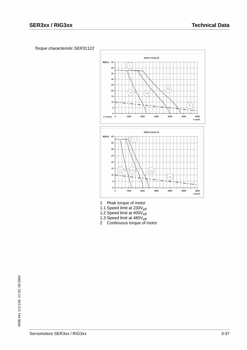
0098
441
113
218
, V1.
02, 0
9.20
04
SER3xx / RIG3xx Technical Data
Torque characteristic SER31122
1 Peak torque of motor1.1 Speed limit at 230Veff1.2 Speed limit at 400Veff1.3 Speed limit at 480Veff2 Continuous torque of motor
SER31122/4L5S
0
5
10
15
20
25
30
35
40
45
0 1000 2000 3000 4000 5000 6000n (1/min)
n [rpm]
M[Nm]
1
2
1.1 1.2
1.3
SER31122/4L7S
0
5
10
15
20
25
30
35
40
0 1000 2000 3000 4000 5000 6000
n [rpm]
M[Nm]
1
2
1.1 1.2 1.3
Servomotors SER3xx / RIG3xx 3-37

Technical Data SER3xx / RIG3xx
0098
441
113
218
, V1.
02, 0
9.20
04
Torque characteristic SER31127
1 Peak torque of motor1.1 Speed limit at 230Veff1.2 Speed limit at 400Veff1.3 Speed limit at 480Veff2 Continuous torque of motor
Shaft load SER 311x The following conditions apply:
• nominal storage life l10h = 20000h1
• speed n = 4000 min-1
• ambient temperature = 40° C
• peak torque = 10% ED
• nominal torque = 100% ED
SER31127/4L5D
0
10
20
30
40
50
60
0 1000 2000 3000 4000
n [rpm]
M[Nm]
1
2
1.2
1.3
SER31127/4L7S
0
10
20
30
40
50
60
0 1000 2000 3000 4000
n [rpm]
M[Nm]
1
2
1.1 1.21.3
1. in operating hours at a failure probability of 10%
3-38 Servomotors SER3xx / RIG3xx
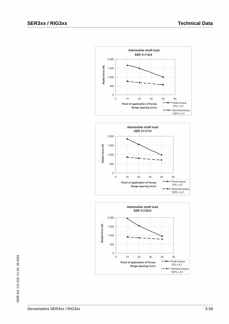
0098
441
113
218
, V1.
02, 0
9.20
04
SER3xx / RIG3xx Technical Data
SER 31112/4
0
500
1.000
1.500
2.000
0 10 20 30 40 50
Admissible shaft load
Point of application of forces
flange spacing (mm)
Rad
ial fo
rce (
N)
Nominal torque,
100% c.d.f.
Peak torque,
10% c.d.f.
SER 31117/4
0
500
1.000
1.500
2.000
0 10 20 30 40 50
Admissible shaft load
Point of application of forces
flange spacing (mm)
Rad
ial fo
rce (
N)
Nominal torque,
100% c.d.f.
Peak torque,
10% c.d.f.
SER 31122/4
0
500
1.000
1.500
2.000
0 10 20 30 40 50
Admissible shaft load
Point of application of forces
flange spacing (mm)
Rad
ial fo
rce (
N)
Nominal torque,
100% c.d.f.
Peak torque,
10% c.d.f.
Servomotors SER3xx / RIG3xx 3-39
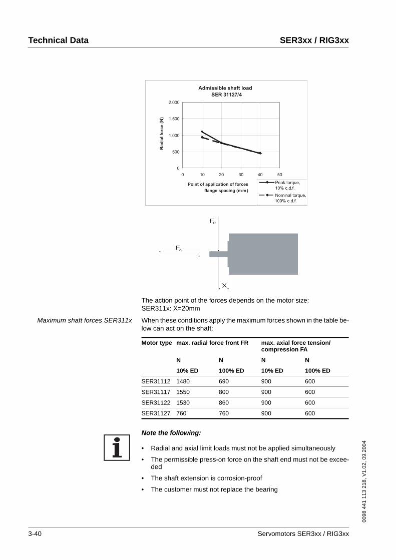
Technical Data SER3xx / RIG3xx
0098
441
113
218
, V1.
02, 0
9.20
04
The action point of the forces depends on the motor size:SER311x: X=20mm
Maximum shaft forces SER311x When these conditions apply the maximum forces shown in the table be-low can act on the shaft:
Note the following:
• Radial and axial limit loads must not be applied simultaneously
• The permissible press-on force on the shaft end must not be excee-ded
• The shaft extension is corrosion-proof
• The customer must not replace the bearing
SER 31127/4
0
500
1.000
1.500
2.000
0 10 20 30 40 50
Admissible shaft load
Point of application of forces
flange spacing (mm)
Rad
ial fo
rce (
N)
Nominal torque,
100% c.d.f.
Peak torque,
10% c.d.f.
X
FA
FR
Motor type max. radial force front FR max. axial force tension/compression FA
N N N N
10% ED 100% ED 10% ED 100% ED
SER31112 1480 690 900 600
SER31117 1550 800 900 600
SER31122 1530 860 900 600
SER31127 760 760 900 600
3-40 Servomotors SER3xx / RIG3xx
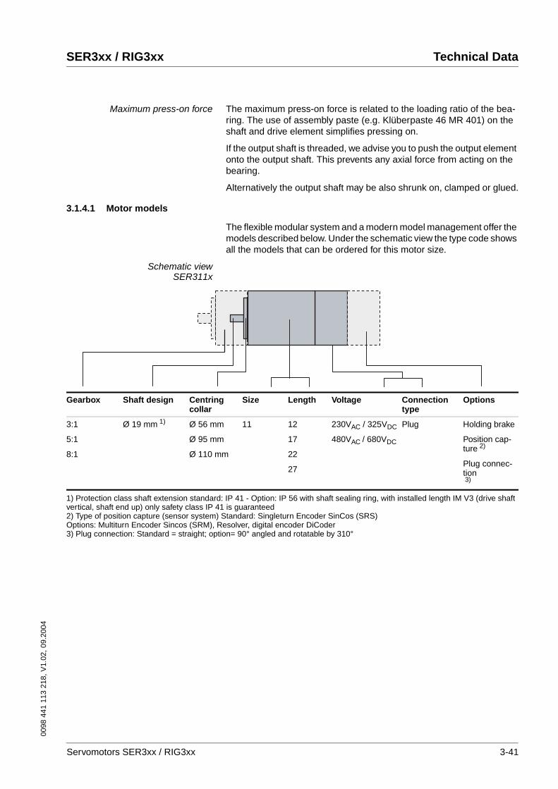
0098
441
113
218
, V1.
02, 0
9.20
04
SER3xx / RIG3xx Technical Data
Maximum press-on force The maximum press-on force is related to the loading ratio of the bea-ring. The use of assembly paste (e.g. Klüberpaste 46 MR 401) on the shaft and drive element simplifies pressing on.
If the output shaft is threaded, we advise you to push the output element onto the output shaft. This prevents any axial force from acting on the bearing.
Alternatively the output shaft may be also shrunk on, clamped or glued.
3.1.4.1 Motor models
The flexible modular system and a modern model management offer the models described below. Under the schematic view the type code shows all the models that can be ordered for this motor size.
Schematic viewSER311x
Gearbox Shaft design Centring collar
Size Length Voltage Connectiontype
Options
3:1
5:1
8:1
Ø 19 mm 1) Ø 56 mm
Ø 95 mm
Ø 110 mm
11 12
17
22
27
230VAC / 325VDC
480VAC / 680VDC
Plug Holding brake
Position cap-ture 2)
Plug connec-tion3)
1) Protection class shaft extension standard: IP 41 - Option: IP 56 with shaft sealing ring, with installed length IM V3 (drive shaft vertical, shaft end up) only safety class IP 41 is guaranteed2) Type of position capture (sensor system) Standard: Singleturn Encoder SinCos (SRS)Options: Multiturn Encoder Sincos (SRM), Resolver, digital encoder DiCoder3) Plug connection: Standard = straight; option= 90° angled and rotatable by 310°
Servomotors SER3xx / RIG3xx 3-41

Technical Data SER3xx / RIG3xx
0098
441
113
218
, V1.
02, 0
9.20
04
Type code SER311xExample: SER 3 X X / 4 L 3 S M O T O I P 4 1 X X X X X X X X
Phase count: 3 SER 3 X X / 4 L 3 S M O T O I P 4 1 X X X X X X X X
Size (flange):11 (110 mm)
SER 3 X X / 4 L 3 S M O T O I P 4 1 X X X X X X X X
Length:12 - 132 mm17 - 180 mm22 - 228 mm27 - 276 mm
SER 3 X X / 4 L 3 S M O T O I P 4 1 X X X X X X X X
Pole pair count: 4 SER 3 X X / 4 L 3 S M O T O I P 4 1 X X X X X X X X
Moment of inertia of rotor:L = low moment of inertia
SER 3 X X / 4 L 3 S M O T O I P 4 1 X X X X X X X X
Winding identification:3; 5; 7
SER 3 X X / 4 L 3 S M O T O I P 4 1 X X X X X X X X
Winding circuit:S = star; D = delta
SER 3 X X / 4 L 3 S M O T O I P 4 1 X X X X X X X X
Sensor system:S = SinCos SingleTurn (S) 1)
M = SinCos MultiTurn (O) 1)
R = resolver (O)
SER 3 X X / 4 L 3 S M O T O I P 4 1 X X X X X X X X
Sensor system resolution:0 for sensor systems S, M, R 2)
0 = 1024 lines for DiCoder6 = 4096 lines for DiCoder
SER 3 X X / 4 L 3 S M O T O I P 4 1 X X X X X X X X
Plug connector:C = straight (S)T = 90° angled (O) 3)
SER 3 X X / 4 L 3 S M O T O I P 4 1 X X X X X X X X
Holding brake:O - without brake (S)B - with brake (O)
SER 3 X X / 4 L 3 S M O T O I P 4 1 X X X X X X X X
Protection class:IP41 - without shaft sealing ring (S)IP56 - with shaft sealing ring (O) 4)
SER 3 X X / 4 L 3 S M O T O I P 4 1 X X X X X X X X
Gearbox type: 5)
3 - PLE 80; 4 - PLE 120 SER 3 X X / 4 L 3 S M O T O I P 4 1 X X X X X X X X
Gear ratio: 5)
3 - 3:1; 5 - 5:1; 8 - 8:1SER 3 X X / 4 L 3 S M O T O I P 4 1 X X X X X X X X
Motor shaft design:K - parallel key DIN 6885O - without parallel key/without gear-box
SER 3 X X / 4 L 3 S M O T O I P 4 1 X X X X X X X X
Centring collar:95 - 95 mm (S)11 - 110 mm (O)56 - 56 mm (O)00 - with gearbox
SER 3 X X / 3 L 4 S M O T O I P 4 1 X X X X X X X X
Temperature sensor:PTC - PTCNTC - NTC
SER 3 X X / 3 L 4 S M O T O I P 4 1 X X X XX X X X
1) (S) = Standart, (O) = Option2) 1024 sine/cosine periods/revolution for SinCos Single/Multiturn; 1 pole-paired for resolver3) 90° angled - rotatable by 310°4) IP 56 with shaft sealing ring, with installation position IM V3 (drive shaft vertical, shaft end up) safety class IP 41 is guaranteed only5) see gearbox type code
3-42 Servomotors SER3xx / RIG3xx

0098
441
113
218
, V1.
02, 0
9.20
04
SER3xx / RIG3xx Technical Data
3.1.4.2 Dimensional drawing
Dimensions SER311x
3.1.4.3 Options
Holding brake
Holding brake SER311x The holding brake is an electromagnetic spring-pressure brake. It holds the motor axis after the motor current is switched off, including after po-wer failure and EMERGENCY STOP. A holding brake is required parti-cularly for torque loads caused by weight forces, such as occur with Z-axes in handling technology. The control is described in Chapter 4.3.2 “Electrical control of the holding brake“.
L
25.625.6
Ø19
j619
j6
ØD
h7
D h
7
4040±0.30.3
14+0.614+0.63±0.20.2
(91.
9)(9
1.9)
(89)
(89)
Ø125.9125.9
110
110±
0.6
0.6
Ø130130R10.
5R1
0.5
9
110110±0.60.6
14.414.4
Ø8585
393933.933.9
23.623.6
5252
5
DIN 332 - DS M6DIN 332 - DS M612 pol12 polEncoderEncoder
8-pol8-polMotorMotor
SER 311xx.SER 311xx.
onlyonlyAbsolut-EncoderAbsolut-Encoder
(DiCoder 17 pol)(DiCoder 17 pol)
MultiTurnMultiTurnFeather key AFeather key A6x6x28 DIN 68856x6x28 DIN 6885
option option ca. 210ca. 210˚
drehbar drehbar ca. 100ca. 100˚
option option ca. 100ca. 100˚
optionoptionca. 210ca. 210˚
fix fix
SER 31112 SER 31117 SER 31122 SER 31127
L (length) [mm] 132 180 228 276
LB (length with brake) [mm] 198 246 294 342
WARNING!Wear or high temperature will cause loss of braking power.
Incorrect use of the holding brake causes accelerated wear and loss of braking power. Heat reduces the holding torque.
• Do not use the brake as a service brake.
• At operating temperatures over 80°C do not exceed a maximum of 50% of the specified holding torque when using the brake.
Failure to follow these instructions can result in death or serious injury.
Technical Data
Nominal voltage [DC] 24 V ±10%
Holding torque 16 Nm
Electrical pick-up power 28 W
Moment of inertia 0.35 kgcm2
Make time (brake ventilation) 60 ms
Break time (close brake) 30 ms
Mass approx. 3 kg
Servomotors SER3xx / RIG3xx 3-43

Technical Data SER3xx / RIG3xx
0098
441
113
218
, V1.
02, 0
9.20
04
Position capture
SinCos Multiturn sensor system(SRM50)
This sensor system measures an absolute value within 4096 revolutions after being switched on and continues to count incrementally from this point.
Resolver sensor system This sensor system is a very robust absolute system. Absolute position capture is possible within one revolution.
Digital encoder sensor system(DiCoder)
This sensor system is an optical (incremental) system.
The data for the sensor systems can be found in Chapter 3.1.1.1 “Posi-tion capture (sensor)“.
Gearbox
Gearbox in general Our servomotors can be combined with the standard gearboxes for your application. The following tables show our motor and gearbox combina-tions.
The listed measured values were determined by continuous output of the maximum torque through the gearbox in your application (maximum acceleration and shortest cycle times to maximum torque).
Under normal operation peak torques cannot be output continuously wi-thout thermal overload of the motor. If the gearbox is selected in accor-dance with the specified values, it will remain in the safe range.
If the motors are not used in the maximum torque range, other gearbo-xes can be selected in accordance with our combination options.
If you have any special requirements in addition to the standard range, please contact our technical support.
The values in bold in the table indicate that the torque is restricted by the gearbox or motor. Uneconomical combinations are indicated with x; the gearbox is overdimensioned or underdimensioned. The index "G" refers to the gearbox output shaft.
CAUTION!The gearbox can be destroyed by overload.
Exceeding the allowable torques will cause accelerated wear, shaft breakage or blocking.
• Do not exceed the peak gearbox torque in any operating status.
• Limit the motor torque if there is a danger of destruction of the gearbox by peak torques.
• Limit the torque in short-time operation (e.g. in an EMER-GENCY STOP situation) to twice the continuous gearbox out-put torque MdG
Failure to follow these instructions can result in injury or equipment damage.
3-44 Servomotors SER3xx / RIG3xx

0098
441
113
218
, V1.
02, 0
9.20
04
SER3xx / RIG3xx Technical Data
Gearbox type PLE Economical precision planetary gearbox
For more information on the gearboxes see Chapter 3.3 “PLE and PLS gearbox“.
Gearbox type PLS High-quality low-play planetary gearbox
For more information on the gearboxes see Chapter 3.3 “PLE and PLS gearbox“.
M d0 Motor Gearbox 3:1 3:1 3:1 5:1 5:1 5:1 8:1 8:1 8:1
M d0 Nm
M d0G1)
NmM dG
2) Nm
M maxG3)
NmM d0G
1) Nm
M dG2)
NmM maxG
3) Nm
M d0G1)
NmM dG
2) Nm
M maxG3)
Nm
4,51 SER31112 PLE 80 13,5 40 54 22,5 50 90 36 50 144
4,5 SER31112 PLE 120 13,5 80 54 22,5 110 90 36 120 144
6,6 SER31117 PLE 120 19,8 80 79,2 33 110 132 52,8 120 211,2
10,0 SER31122 PLE 120 30 80 120 50 110 200 80 120 320
13,42 SER31127 PLE 120 40,2 80 160,8 67 110 268 107,2 120 428,8
6,69 SER31117 PLE 160 x x x 33 450 132 52,8 450 211,2
10,0 SER31122 PLE 160 30 400 120 50 450 200 80 450 320
13,4 SER31127 PLE 160 40,2 400 160,8 67 450 268 107,2 450 428,8
1) Md0G Nominal torque at low speed = guide value for selection of the gearbox2) MdG Gearbox output torque (continuous torque)3) MmaxG Max. output torque with this motor - (theoretical value, calculated from max. motor torque Mmax *ratio)
M d0 Motor Gearbox 3:1 3:1 3:1 5:1 5:1 5:1 8:1 8:1 8:1
M d0 Nm
M d0G1)
NmM dG
2) Nm
M maxG3)
NmM d0G
1) Nm
M dG2)
NmM maxG
3) Nm
M d0G1)
NmM dG
2) Nm
M maxG3)
Nm
4,5 SER31112 PLS 90 13,5 75 54 22,5 110 90 36 62 144
6,6 SER31117 PLS 90 19,8 75 79,2 33 110 132 52,8 62 211,2
10,0 SER31122 PLS 90 30 75 120 50 110 200 x x x
13,4 SER31127 PLS 90 40,2 75 160,82 67 110 268 x x x
4,5 SER31112 PLS 115 x x x x x x 36 148 144
6,6 SER31117 PLS 115 x x x 33 210 132 52,8 148 211,2
10,0 SER31122 PLS 115 30 150 120 50 210 200 80 148 320
13,4 SER31127 PLS 115 40,2 150 160,8 67 210 268 107,2 148 428,8
6,6 SER31117 PLS 142 x x x x x x 52,8 450 211,2
10,0 SER31122 PLS 142 x x x x x x 80 450 320
13,4 SER31127 PLS 142 40,2 400 160,8 67 700 268 107,2 450 428,8
1) Md0G Nominal torque at low speed = guide value for selection of the gearbox2) MdG Gearbox output torque (continuous torque)3) MmaxG Max. output torque with this motor - (theoretical value, calculated from max. motor torque Mmax *ratio)
Servomotors SER3xx / RIG3xx 3-45

Technical Data SER3xx / RIG3xx
0098
441
113
218
, V1.
02, 0
9.20
04
3.2 RIG3xx
3.2.1 RIG3xx general
Series RIG3xx The motors of the RIG3xx series are 8-pole AC synchronous servomo-tors with a 4:1 ratio gearbox integrated into the motor.
They are distinguished by:
• high power density
• integrated thermal winding monitoring
• insulation test voltage in accordance with DIN EN 60034-1 (IEC 60034-1)
• insulation class F in accordance with DIN EN 60034-1 (IEC 60034-1)
• vibration grade R in accordance with DIN EN 60034-14 (IEC 60034-14)
• shaft eccentricity and axial precision in accordance with DIN 42955 N (IEC 60072-1)
• colour: black RAL 9005
• very short design
• highly dynamic
Environmental influences: ambientoperating climate
Environmental influences: ambientclimate for transport and storage
The motors must be in a dry, dust-free and vibration-free environment during transport and storage. The storage and transport temperature must remain in the range given below; in case of doubt the storage area must be air-conditioned.
The storage period is primarily determined by the durability of the lubri-cants in the warehouses and should be less than 36 months. Occasional operation of the drive solution is recommended to ensure that it still ope-rates.
Service life The service life of the motors when operated correctly is limited primarily by the bearing life.
The following operating conditions can in some cases significantly re-duce the service life:
• Installation altitude above 1000 m over sea level
• Rotary movement exclusively within a fixed angle of 100°
• Operation under vibration stress greater than 20 m/s2
• Allowing sealing rings to run dry
• Wetting gaskets with aggressive media
Temperature (t) -20°C to +40°C
Humidity 75%rh annual average
95%rh on 30 days (non-condensing)
Storage and transport temperature -25°C to +70°C
3-46 Servomotors SER3xx / RIG3xx
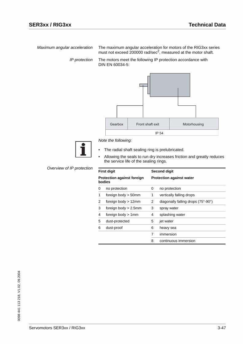
0098
441
113
218
, V1.
02, 0
9.20
04
SER3xx / RIG3xx Technical Data
Maximum angular acceleration The maximum angular acceleration for motors of the RIG3xx series must not exceed 200000 rad/sec2, measured at the motor shaft.
IP protection The motors meet the following IP protection accordance with DIN EN 60034-5:
Note the following:
• The radial shaft sealing ring is prelubricated.
• Allowing the seals to run dry increases friction and greatly reduces the service life of the sealing rings.
Overview of IP protection
Gearbox Front shaft exit Motorhousing
IP 54
First digit Second digit
Protection against foreign bodies
Protection against water
0 no protection 0 no protection
1 foreign body > 50mm 1 vertically falling drops
2 foreign body > 12mm 2 diagonally falling drops (75°-90°)
3 foreign body > 2.5mm 3 spray water
4 foreign body > 1mm 4 splashing water
5 dust-protected 5 jet water
6 dust-proof 6 heavy sea
7 immersion
8 continuous immersion
Servomotors SER3xx / RIG3xx 3-47
Technical Data SER3xx / RIG3xx
0098
441
113
218
, V1.
02, 0
9.20
04
3.2.1.1 Position capture (sensor)
Standard position capture
SinCos (SRS50) Singleturn This sensor system measures an absolute value within one revolution after being switched on and continues to count incrementally from this point.
For more information see www.stegmann.de
Optional position capture
As an alternative to the standard sensor system the motors can also be ordered with one of the following sensor systems:
SinCos (SRM50) Multiturn This sensor system measures an absolute value within 4096 revolutions after being switched on and continues to count incrementally from this point.
For more information see www.stegmann.de
Resolver This sensor system is very robust. Absolute position capture is possible within one revolution.
Resolution depends on controller
Measurement range absolute 1 revolution
Error limit of the digital absolute value depending on the controller
±1.5 minutes of arc
Precision of the incremental posi-tion evaluation
±0.75 minutes of arc
Pulse shape sinus
Supply voltage 7-12V (8V recommended)
Supply current max. 80mA (without load)
Resolution depends on controller
Measurement range absolute 4096 revolutions
Error limit of the digital absolute value depending on the controller
±1.5 minutes of arc
Precision of the incremental posi-tion evaluation
±0.75 minutes of arc
Pulse shape sinus
Supply voltage 7-12V (8V recommended)
Supply current max. 80mA (without load)
Resolution depends on the controller
Measurement range absolute 1 revolution
Precision of the incremental posi-tion evaluation
±6 minutes of arc
Input voltage 7Veff
Input current max. 38mA
3-48 Servomotors SER3xx / RIG3xx

0098
441
113
218
, V1.
02, 0
9.20
04
SER3xx / RIG3xx Technical Data
Digital encoder (DiCoder) This sensor system is an optical (incremental) system. It is only available for the SER39x and SER311x motor series, it is not available for SER36x.
For more information see www.stegmann.de
Resolution 1024 and 4096 bars/revolution
Measurement range absolute 1 revolution
Precision ±2 minutes of arc
Signals A, B, C, commutation
Pulse shape rectangular
Supply voltage 5V ± 10%
Supply current max. 50mA (without load)
Servomotors SER3xx / RIG3xx 3-49
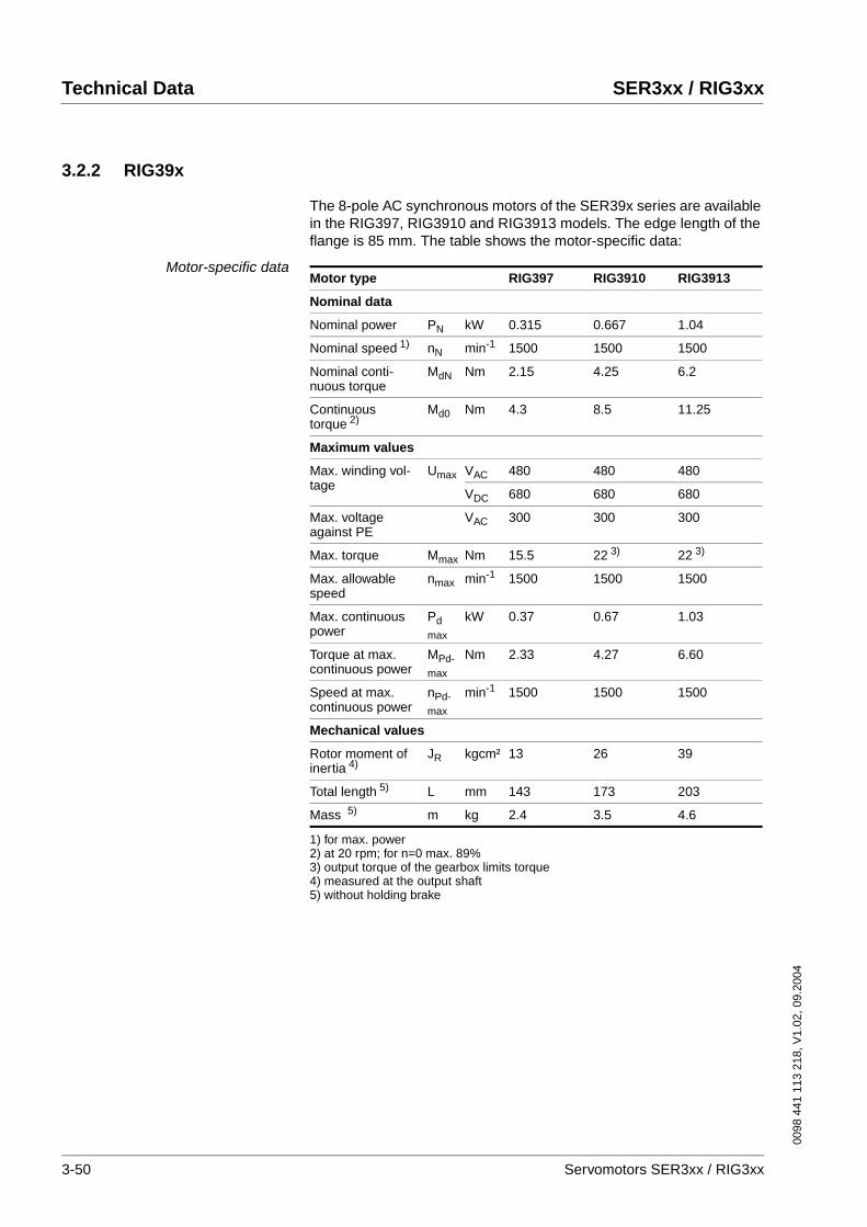
Technical Data SER3xx / RIG3xx
0098
441
113
218
, V1.
02, 0
9.20
04
3.2.2 RIG39x
The 8-pole AC synchronous motors of the SER39x series are available in the RIG397, RIG3910 and RIG3913 models. The edge length of the flange is 85 mm. The table shows the motor-specific data:
Motor-specific dataMotor type RIG397 RIG3910 RIG3913
Nominal data
Nominal power PN kW 0.315 0.667 1.04
Nominal speed 1)
1) for max. power
nN min-1 1500 1500 1500
Nominal conti-nuous torque
MdN Nm 2.15 4.25 6.2
Continuous torque 2)
2) at 20 rpm; for n=0 max. 89%
Md0 Nm 4.3 8.5 11.25
Maximum values
Max. winding vol-tage
Umax VAC 480 480 480
VDC 680 680 680
Max. voltage against PE
VAC 300 300 300
Max. torque Mmax Nm 15.5 22 3)
3) output torque of the gearbox limits torque
22 3)
Max. allowable speed
nmax min-1 1500 1500 1500
Max. continuous power
Pdmax
kW 0.37 0.67 1.03
Torque at max. continuous power
MPd-max
Nm 2.33 4.27 6.60
Speed at max. continuous power
nPd-max
min-1 1500 1500 1500
Mechanical values
Rotor moment of inertia 4)
4) measured at the output shaft
JR kgcm² 13 26 39
Total length 5)
5) without holding brake
L mm 143 173 203
Mass 5) m kg 2.4 3.5 4.6
3-50 Servomotors SER3xx / RIG3xx
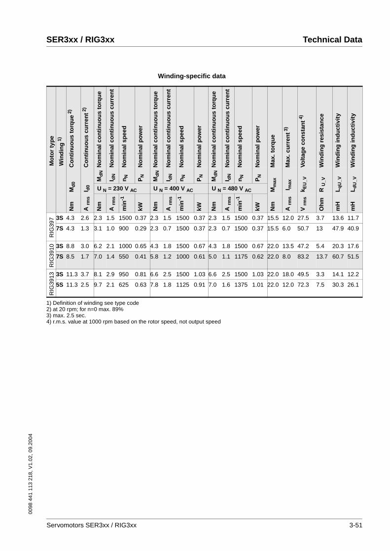
0098
441
113
218
, V1.
02, 0
9.20
04
SER3xx / RIG3xx Technical Data
Winding-specific data
Mo
tor
typ
e
Win
din
g1)
Co
nti
nu
ou
s to
rqu
e2)
Co
nti
nu
ou
s cu
rren
t2)
No
min
al c
on
tin
uo
us
torq
ue
No
min
al c
on
tin
uo
us
curr
ent
No
min
al s
pee
d
No
min
al p
ow
er
No
min
al c
on
tin
uo
us
torq
ue
No
min
al c
on
tin
uo
us
curr
ent
No
min
al s
pee
d
No
min
al p
ow
er
No
min
al c
on
tin
uo
us
torq
ue
No
min
al c
on
tin
uo
us
curr
ent
No
min
al s
pee
d
No
min
al p
ow
er
Max
. to
rqu
e
Max
. cu
rren
t3)
Volt
age
con
stan
t4)
Win
din
g r
esis
tan
ce
Win
din
g in
du
ctiv
ity
Win
din
g in
du
ctiv
ity
Md
0
I d0
Md
N
I dN
nN
PN
Md
N
I dN
nN
PN
Md
N
I dN
nN
PN
Mm
ax
I max
k EU
_V
R U
_V
Lq
U_V
Ld
U_V
U N = 230 V AC U N = 400 V AC U N = 480 V AC
Nm
A rm
s
Nm
A rm
s
min
-1
kW Nm
A rm
s
min
-1
kW Nm
A rm
s
min
-1
kW Nm
A rm
s
V rm
s
Oh
m
mH
mH
RIG
397 3S 4.3 2.6 2.3 1.5 1500 0.37 2.3 1.5 1500 0.37 2.3 1.5 1500 0.37 15.5 12.0 27.5 3.7 13.6 11.7
7S 4.3 1.3 3.1 1.0 900 0.29 2.3 0.7 1500 0.37 2.3 0.7 1500 0.37 15.5 6.0 50.7 13 47.9 40.9
RIG
3910 3S 8.8 3.0 6.2 2.1 1000 0.65 4.3 1.8 1500 0.67 4.3 1.8 1500 0.67 22.0 13.5 47.2 5.4 20.3 17.6
7S 8.5 1.7 7.0 1.4 550 0.41 5.8 1.2 1000 0.61 5.0 1.1 1175 0.62 22.0 8.0 83.2 13.7 60.7 51.5
RIG
3913 3S 11.3 3.7 8.1 2.9 950 0.81 6.6 2.5 1500 1.03 6.6 2.5 1500 1.03 22.0 18.0 49.5 3.3 14.1 12.2
5S 11.3 2.5 9.7 2.1 625 0.63 7.8 1.8 1125 0.91 7.0 1.6 1375 1.01 22.0 12.0 72.3 7.5 30.3 26.1
1) Definition of winding see type code2) at 20 rpm; for n=0 max. 89%3) max. 2.5 sec.4) r.m.s. value at 1000 rpm based on the rotor speed, not output speed
Servomotors SER3xx / RIG3xx 3-51
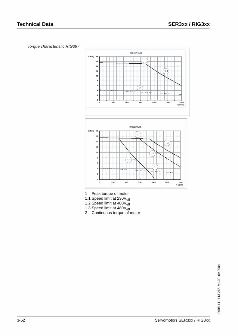
Technical Data SER3xx / RIG3xx
0098
441
113
218
, V1.
02, 0
9.20
04
Torque characteristic RIG397
1 Peak torque of motor1.1 Speed limit at 230Veff1.2 Speed limit at 400Veff1.3 Speed limit at 480Veff2 Continuous torque of motor
RIG397/4L3S
0
2
4
6
8
10
12
14
16
18
0 250 500 750 1000 1250 1500
n [rpm]
M[Nm]
1
1.1
2
RIG397/4L7S
0
2
4
6
8
10
12
14
16
18
0 250 500 750 1000 1250 1500
n [rpm]
M[Nm]
1
1.3
1.2
1.1
2
3-52 Servomotors SER3xx / RIG3xx
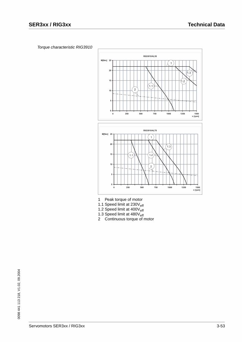
0098
441
113
218
, V1.
02, 0
9.20
04
SER3xx / RIG3xx Technical Data
Torque characteristic RIG3910
1 Peak torque of motor1.1 Speed limit at 230Veff1.2 Speed limit at 400Veff1.3 Speed limit at 480Veff2 Continuous torque of motor
RIG3910/4L3S
0
5
10
15
20
25
0 250 500 750 1000 1250 1500
n [rpm]
M[Nm]
1
1.3
1.2
1.1
2
RIG3910/4L7S
0
5
10
15
20
25
0 250 500 750 1000 1250 1500
n [rpm]
M[Nm]
1
1.3
1.21.1
2
Servomotors SER3xx / RIG3xx 3-53
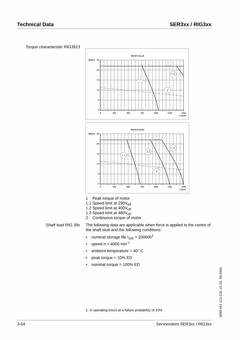
Technical Data SER3xx / RIG3xx
0098
441
113
218
, V1.
02, 0
9.20
04
Torque characteristic RIG3913
1 Peak torque of motor1.1 Speed limit at 230Veff1.2 Speed limit at 400Veff1.3 Speed limit at 480Veff2 Continuous torque of motor
Shaft load RIG 39x The following data are applicable when force is applied to the centre of the shaft stub and the following conditions:
• nominal storage life l10h = 20000h1
• speed n = 4000 min-1
• ambient temperature = 40° C
• peak torque = 10% ED
• nominal torque = 100% ED
RIG3913/4L3S
0
5
10
15
20
25
0 250 500 750 1000 1250 1500
n [rpm]
M[Nm]
1.1
2
1.2
1
RIG3913/4L5S
0
5
10
15
20
25
0 250 500 750 1000 1250 1500
n [rpm]
M[Nm]
1
1.1
1.2
1.3
2
1. in operating hours at a failure probability of 10%
3-54 Servomotors SER3xx / RIG3xx
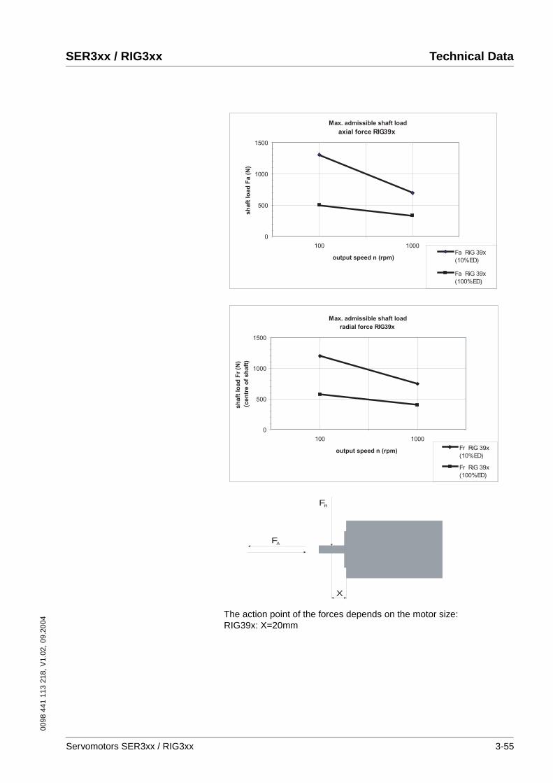
0098
441
113
218
, V1.
02, 0
9.20
04
SER3xx / RIG3xx Technical Data
The action point of the forces depends on the motor size:RIG39x: X=20mm
Max. admissible shaft load
axial force RIG39x
0
500
1000
1500
100 1000
output speed n (rpm)
sh
aft
lo
ad
Fa (
N)
Fa RiG 39x
(10%ED)
Fa RiG 39x
(100%ED)
Max. admissible shaft load
radial force RIG39x
0
500
1000
1500
100 1000
output speed n (rpm)
sh
aft
lo
ad
Fr
(N)
(cen
tre o
f sh
aft
)
Fr RiG 39x
(10%ED)
Fr RiG 39x
(100%ED)
X
FA
FR
Servomotors SER3xx / RIG3xx 3-55
Technical Data SER3xx / RIG3xx
0098
441
113
218
, V1.
02, 0
9.20
04
Max. shaft forces for RIG39x When these conditions apply the maximum forces shown in the table be-low can act on the shaft:
Note the following:
• Radial and axial limit loads must not be applied simultaneously
• The permissible press-on force on the shaft end must not be excee-ded
• The shaft extension is corrosion-proof
• The customer must not replace the bearing
For RIG39x the allowable press-on force on the shaft end is 1300N.
Maximum press-on force The maximum press-on force is related to the loading ratio of the bea-ring. The use of assembly paste (e.g. Klüberpaste 46 MR 401) on the shaft and drive element simplifies pressing on.
If the output shaft is threaded, we advise you to push the output element onto the output shaft. This prevents any axial force from acting on the bearing.
Alternatively the output shaft may be also shrunk on, clamped or glued.
The opening in the shaft end must remain open for pressure compensation (normal pressure).
Motor type max. radial force front FR max. axial force tension/compression FA
N N N N
10% ED 100% ED 10% ED 100% ED
RIG397 1200 570 1300 500
RIG3910 1200 570 1300 500
RIG3913 1200 570 1300 500
3-56 Servomotors SER3xx / RIG3xx
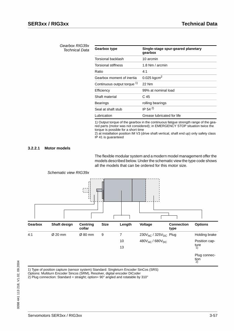
0098
441
113
218
, V1.
02, 0
9.20
04
SER3xx / RIG3xx Technical Data
Gearbox RIG39xTechnical Data
3.2.2.1 Motor models
The flexible modular system and a modern model management offer the models described below. Under the schematic view the type code shows all the models that can be ordered for this motor size.
Schematic view RIG39x
Gearbox type Single-stage spur-geared planetary gearbox
Torsional backlash 10 arcmin
Torsional stiffness 1.8 Nm / arcmin
Ratio 4:1
Gearbox moment of inertia 0.025 kgcm2
Continuous output torque 1)
1) Output torque of the gearbox in the continuous fatigue strength range of the gea-red parts (motor was not considered); in EMERGENCY STOP situation twice the torque is possible for a short time
22 Nm
Efficiency 99% at nominal load
Shaft material C 45
Bearings rolling bearings
Seal at shaft stub IP 54 2)
2) at installation position IM V3 (drive shaft vertical, shaft end up) only safety class IP 41 is guaranteed
Lubrication Grease lubricated for life
Gearbox Shaft design Centring collar
Size Length Voltage Connectiontype
Options
4:1 Ø 20 mm Ø 80 mm 9 7
10
13
230VAC / 325VDC
480VAC / 680VDC
Plug Holding brake
Position cap-ture1)
Plug connec-tion2)
1) Type of position capture (sensor system) Standard: Singleturn Encoder SinCos (SRS)Options: Multiturn Encoder Sincos (SRM), Resolver, digital encoder DiCoder2) Plug connection: Standard = straight; option= 90° angled and rotatable by 310°
Servomotors SER3xx / RIG3xx 3-57

Technical Data SER3xx / RIG3xx
0098
441
113
218
, V1.
02, 0
9.20
04
Type code RIG39xExample: RIG 3 X X / 4 L 3 S M O T O I P 5 4 X X X X X X X X
Phase count: 3 RIG 3 X X / 4 L 3 S M O T O I P 5 4 X X X X X X X X
Size (flange):9 (85 mm)
RIG 3 X X / 4 L 3 S M O T O I P 5 4 X X X X X X X X
Length:7 - 143 mm10 - 173 mm13 - 203 mm
RIG 3 X X / 4 L 3 S M O T O I P 5 4 X X X X X X X X
Pole pair count: 4 RIG 3 X X / 4 L 3 S M O T O I P 5 4 X X X X X X X X
Moment of inertia of rotor:L = low moment of inertia
RIG 3 X X / 4 L 3 S M O T O I P 5 4 X X X X X X X X
Winding identification:3; 5; 7
RIG 3 X X / 4 L 3 S M O T O I P 5 4 X X X X X X X X
Winding circuit:S = star D = delta
RIG 3 X X / 4 L 3 S M O T O I P 5 4 X X X X X X X X
Sensor system:S = SinCos SingleTurn (S) 1)
M = SinCos MultiTurn (O) 1)
R = resolver (O)
RIG 3 X X / 4 L 3 S M O T O I P 5 4 X X X X X X X X
Sensor system resolution:0 for sensor systems S, M, R 2)
0 = 1024 lines for DiCoder6 = 4096 lines for DiCoder
RIG 3 X X / 4 L S M O T O I P 5 4 X X X X X X X X
Plug connector: C = straight (S)T = 90° angled (O) 3)
RIG 3 X X / 4 L 3 S M O T O I P 5 4 X X X X X X X X
Holding brake:O - without brake (S)B - with brake (O)
RIG 3 X X / 4 L 3 S M O T O I P 5 4 X X X X X X X X
Protection class:IP54 - without shaft sealing ring 4)
RIG 3 X X / 4 L 3 S M O T O I P 5 4 X X X X X X X X
Gearbox type: 5)
I - integrated gearboxRIG 3 X X / 4 L 3 S M O T O I P 5 4 X X X X X X X X
Gear ratio: 5)
4 - 4:1RIG 3 X X / 4 L 3 S M O T O I P 5 4 X X X X X X X X
Motor shaft design:O - without parallel key/without gear-box
RIG 3 X X / 4 L 3 S M O T O I P 5 4 X X X X X X X X
Centring collar:80 - 80 mm
RIG 3 X X / 3 L 4 S M O T O I P 5 4 X X X X X X X X
Temperature sensor:PTC - PTCNTC - NTC
RIG 3 X X / 3 L 4 S M O T O I P 5 4 X X X XX X X X
1) (S) = Standard, (O) = Option2) 1024 sine/cosine periods/revolution for SinCos Single/Multiturn; 1 pole-paired for resolver3) 90° angled - rotatable by 310°4) with installation position IM V3 (drive shaft vertical, shaft end up) only guaranteed for safety class IP 415) see gearbox type code
3-58 Servomotors SER3xx / RIG3xx
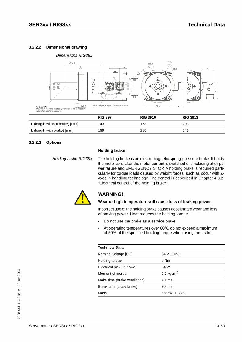
0098
441
113
218
, V1.
02, 0
9.20
04
SER3xx / RIG3xx Technical Data
3.2.2.2 Dimensional drawing
Dimensions RIG39x
3.2.2.3 Options
Holding brake
Holding brake RIG39x The holding brake is an electromagnetic spring-pressure brake. It holds the motor axis after the motor current is switched off, including after po-wer failure and EMERGENCY STOP. A holding brake is required parti-cularly for torque loads caused by weight forces, such as occur with Z-axes in handling technology. The control is described in Chapter 4.3.2 “Electrical control of the holding brake“.
Signal receptacleMotor receptacle 8-pinATTENTION!
The hole in shaft end must be open for pressure equalization (Normal atmospheric pressure).
rotatable
rotatable
rotatable
stop
rotatable
RIG 397 RIG 3910 RIG 3913
L (length without brake) [mm] 143 173 203
L (length with brake) [mm] 189 219 249
WARNING!Wear or high temperature will cause loss of braking power.
Incorrect use of the holding brake causes accelerated wear and loss of braking power. Heat reduces the holding torque.
• Do not use the brake as a service brake.
• At operating temperatures over 80°C do not exceed a maximum of 50% of the specified holding torque when using the brake.
Failure to follow these instructions can result in death or serious injury.
Technical Data
Nominal voltage [DC] 24 V ±10%
Holding torque 6 Nm
Electrical pick-up power 24 W
Moment of inertia 0.2 kgcm2
Make time (brake ventilation) 40 ms
Break time (close brake) 20 ms
Mass approx. 1.8 kg
Servomotors SER3xx / RIG3xx 3-59
Technical Data SER3xx / RIG3xx
0098
441
113
218
, V1.
02, 0
9.20
04
Position capture
SinCos Multiturn sensor system(SRM50)
This sensor system measures an absolute value within 4096 revolutions after being switched on and continues to count incrementally from this point.
Resolver sensor system This sensor system is a very robust absolute system. Absolute position capture is possible within one revolution.
Digital encoder sensor system(DiCoder)
This sensor system is an optical (incremental) system.
The data for the sensor systems can be found in Chapter 3.1.1.1 “Posi-tion capture (sensor)“.
3-60 Servomotors SER3xx / RIG3xx

0098
441
113
218
, V1.
02, 0
9.20
04
SER3xx / RIG3xx Technical Data
3.2.3 RIG311x
The 8-pole AC synchronous motors of the RIG311x series are available in the RIG31112, RIG31117 and RIG31122 models. The edge length of the flange is 110 mm. The table shows the motor-specific data:
Motor-specific dataMotor type RIG31112 RIG31117 RIG31122
Nominal data
Nominal power PN kW 0.9 1.3 1.8
Nominal speed 1)
1) for max. power
nN min-1 1175 1000 1000
Nominal conti-nuous torque
MdN Nm 8.5 12.8 19.4
Continuous torque 2)
2) at 20 rpm; for n=0 max. 89%
Md0 Nm 16.2 25.6 38.8
Maximum values
Max. winding vol-tage
Umax VAC 480 480 480
VDC 680 680 680
Max. voltage against PE
VAC 300 300 300
Max. torque Mmax Nm 70 76 3)
3) output torque of the gearbox limits torque
76 3)
Max. allowable speed
nmax min-1 1500 1500 1500
Max. continuous power
Pdmax
kW 1.00 1.34 2.03
Torque at max. con-tinuous power
MPd-max
Nm 8.1 12.8 19.4
Speed at max. con-tinuous power
nPd-max
min-1 1175 1000 1000
Mechanical values
Rotor moment of inertia 4)
4) measured at the output shaft
JR kgcm² 66 130 178
Total length 5)
5) without holding brake
L mm 145 193 241
Mass 5) m kg 6.2 9.2 12.2
Servomotors SER3xx / RIG3xx 3-61

Technical Data SER3xx / RIG3xx
0098
441
113
218
, V1.
02, 0
9.20
04
Winding-specific data
Mo
tor
typ
e
Win
din
g1)
Co
nti
nu
ou
s to
rqu
e2)
Co
nti
nu
ou
s cu
rren
t2)
No
min
al c
on
tin
uo
us
torq
ue
No
min
al c
on
tin
uo
us
curr
ent
No
min
al s
pee
d
No
min
al p
ow
er
No
min
al c
on
tin
uo
us
torq
ue
No
min
al c
on
tin
uo
us
curr
ent
No
min
al s
pee
d
No
min
al p
ow
er
No
min
al c
on
tin
uo
us
torq
ue
No
min
al c
on
tin
uo
us
curr
ent
No
min
al s
pee
d
No
min
al p
ow
er
Max
. to
rqu
e
Max
. cu
rren
t3)
Volt
age
con
stan
t4)
Win
din
g r
esis
tan
ce
Win
din
g in
du
ctiv
ity
Win
din
g in
du
ctiv
ity
Md
0
I d0
Md
N
I dN
nN
PN
Md
N
I dN
nN
PN
Md
N
I dN
nN
PN
Mm
ax
I max
k EU
_V
R U
_V
Lq
U_V
Ld
U_V
U N = 230 V AC U N = 400 V AC U N = 480 V AC
Nm
A rm
s
Nm
A rm
s
min
-1
kW Nm
A rm
s
min
-1
kW Nm
A rm
s
min
-1
kW Nm
A rm
s
V rm
s
Oh
m
mH
mH
RIG
3111
2 3S 16.3 6.0 9.7 3.5 1000 1.02 5.8 2.1 1500 0.91 5.8 2.1 1500 0.91 65.2 30.0 43.3 1.5 12.6 9.7
5S 16.3 3.6 12.8 2.8 550 0.74 9.7 2.1 1000 1.02 7.8 1.7 1250 1.02 76.0 18.0 70.7 4.0 34.1 26.6
7S 16.3 1.8 15.5 1.7 250 0.41 13.2 1.5 500 0.69 12.4 1.4 600 0.78 76.0 9.0 140.0 18.1 141 107
RIG
3111
7 3S 25.6 6.6 14.0 3.8 825 1.20 5.8 1.7 1500 0.91 5.8 1.7 1500 0.91 76.0 32.0 58.4 1.2 11.3 8.3
5S 25.6 5.0 16.3 3.3 600 1.03 12.8 2.6 1000 1.34 10.1 2.1 1225 1.29 76.0 24.0 82.0 2.3 21.2 15.4
7S 25.6 2.7 21.3 2.3 312 0.70 17.8 2.0 562 1.02 17.5 1.9 625 1.14 76.0 12.5 148.4 7.4 70.2 51.8
RIG
3111
2 5S 38.8 7.0 17.5 3.0 562 1.03 19.4 3.5 1000 2.09 17.8 3.3 1075 2.01 76.0 32.0 90.9 1.7 17.2 12.4
7S 38.8 3.6 31.8 3.0 250 0.83 29.1 2.8 500 1.52 27.9 2.6 562 1.65 76.0 16.5 176 5.7 62.5 45.7
1) Definition of winding see type code2) at 20 rpm; for n=0 max. 89%3) max. 2.5 sec.4) r.m.s. value at 1000 rpm based on the rotor speed, not output speed
3-62 Servomotors SER3xx / RIG3xx
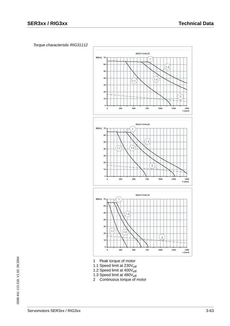
0098
441
113
218
, V1.
02, 0
9.20
04
SER3xx / RIG3xx Technical Data
Torque characteristic RIG31112
1 Peak torque of motor1.1 Speed limit at 230Veff1.2 Speed limit at 400Veff1.3 Speed limit at 480Veff2 Continuous torque of motor
RIG31112/4L3S
0
10
20
30
40
50
60
70
0 250 500 750 1000 1250 1500
n [rpm]
M[Nm]1
2
1.3
1.21.1
RIG31112/4L5S
0
10
20
30
40
50
60
70
0 250 500 750 1000 1250 1500
n [rpm]
M[Nm] 1
2
1.3
1.21.1
RIG31112/4L7S
0
10
20
30
40
50
60
70
0 250 500 750 1000 1250 1500
n [rpm]
M[Nm] 1
2
1.3
1.21.1
Servomotors SER3xx / RIG3xx 3-63
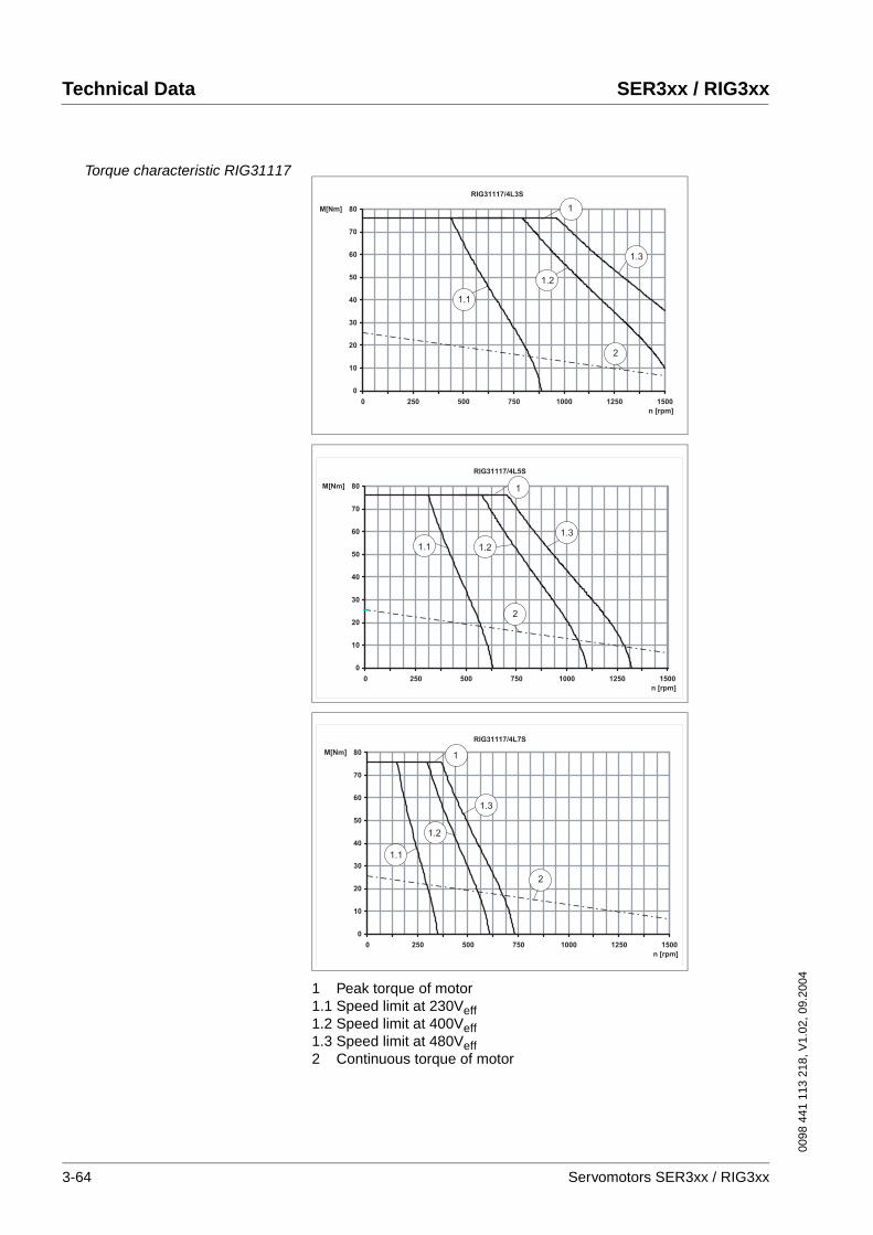
Technical Data SER3xx / RIG3xx
0098
441
113
218
, V1.
02, 0
9.20
04
Torque characteristic RIG31117
1 Peak torque of motor1.1 Speed limit at 230Veff1.2 Speed limit at 400Veff1.3 Speed limit at 480Veff2 Continuous torque of motor
RIG31117/4L3S
0
10
20
30
40
50
60
70
80
0 250 500 750 1000 1250 1500
n [rpm]
M[Nm] 1
2
1.1
1.2
1.3
RIG31117/4L5S
0
10
20
30
40
50
60
70
80
0 250 500 750 1000 1250 1500
n [rpm]
M[Nm] 1
2
1.3
1.21.1
RIG31117/4L7S
0
10
20
30
40
50
60
70
80
0 250 500 750 1000 1250 1500
n [rpm]
M[Nm] 1
2
1.3
1.2
1.1
3-64 Servomotors SER3xx / RIG3xx
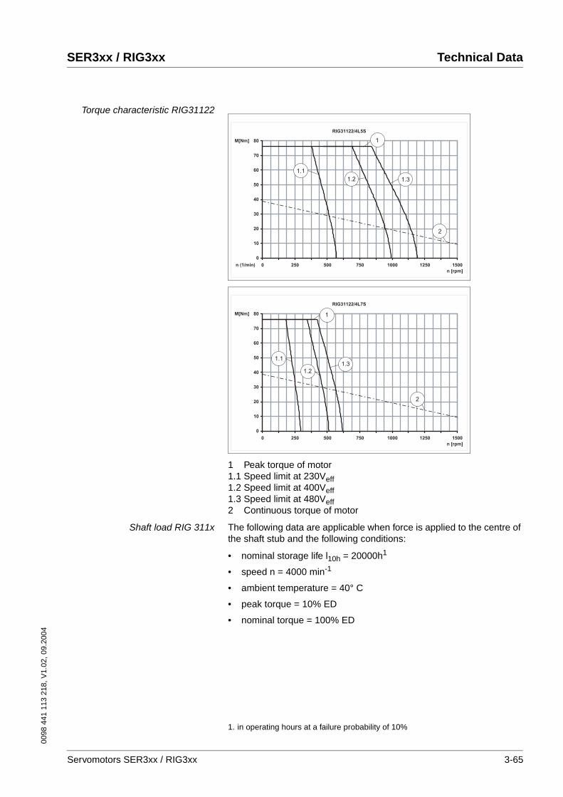
0098
441
113
218
, V1.
02, 0
9.20
04
SER3xx / RIG3xx Technical Data
Torque characteristic RIG31122
1 Peak torque of motor1.1 Speed limit at 230Veff1.2 Speed limit at 400Veff1.3 Speed limit at 480Veff2 Continuous torque of motor
Shaft load RIG 311x The following data are applicable when force is applied to the centre of the shaft stub and the following conditions:
• nominal storage life l10h = 20000h1
• speed n = 4000 min-1
• ambient temperature = 40° C
• peak torque = 10% ED
• nominal torque = 100% ED
RIG31122/4L5S
0
10
20
30
40
50
60
70
80
0 250 500 750 1000 1250 1500n (1/min)
n [rpm]
M[Nm]
2
1
1.31.2
1.1
RIG31122/4L7S
0
10
20
30
40
50
60
70
80
0 250 500 750 1000 1250 1500
n [rpm]
M[Nm] 1
2
1.3
1.2
1.1
1. in operating hours at a failure probability of 10%
Servomotors SER3xx / RIG3xx 3-65
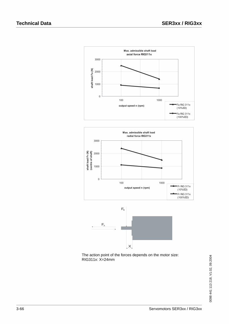
Technical Data SER3xx / RIG3xx
0098
441
113
218
, V1.
02, 0
9.20
04
The action point of the forces depends on the motor size:RIG311x: X=24mm
Max. admissible shaft load
axial force RIG311x
0
1000
2000
3000
100 1000
output speed n (rpm)
sh
aft
lo
ad
Fa (
N)
Fa RiG 311x
(10%ED)
Fa RiG 311x
(100%ED)
Max. admissible shaft load
radial force RIG311x
0
1000
2000
3000
100 1000
output speed n (rpm)
sh
aft
lo
ad
Fr
(N)
(cen
tre o
f sh
aft
)
Fr RiG 311x
(10%ED)
Fr RiG 311x
(100%ED)
X
FA
FR
3-66 Servomotors SER3xx / RIG3xx
0098
441
113
218
, V1.
02, 0
9.20
04
SER3xx / RIG3xx Technical Data
Max. shaft forces for RIG311x When these conditions apply the maximum forces shown in the table be-low can act on the shaft:
Note the following:
• Radial and axial limit loads must not be applied simultaneously
• The permissible press-on force on the shaft end must not be excee-ded
• The shaft extension is corrosion-proof
• The customer must not replace the bearing
For RIG311x the allowable press-on force on the shaft end is 1300N.
Maximum press-on force The maximum press-on force is related to the loading ratio of the bea-ring. The use of assembly paste (e.g. Klüberpaste 46 MR 401) on the shaft and drive element simplifies pressing on.
If the output shaft is threaded, we advise you to push the output element onto the output shaft. This prevents any axial force from acting on the bearing.
Alternatively the output shaft may be also shrunk on, clamped or glued.
The opening in the shaft end must remain open for pressure compensation (normal pressure).
Motor type max. radial force front FR max. axial force tension/compression FA
N N N N
10% ED 100% ED 10% ED 100% ED
RIG31112 2400 1100 2500 900
RIG31117 2400 1100 2500 900
RIG31122 2400 1100 2500 900
Servomotors SER3xx / RIG3xx 3-67
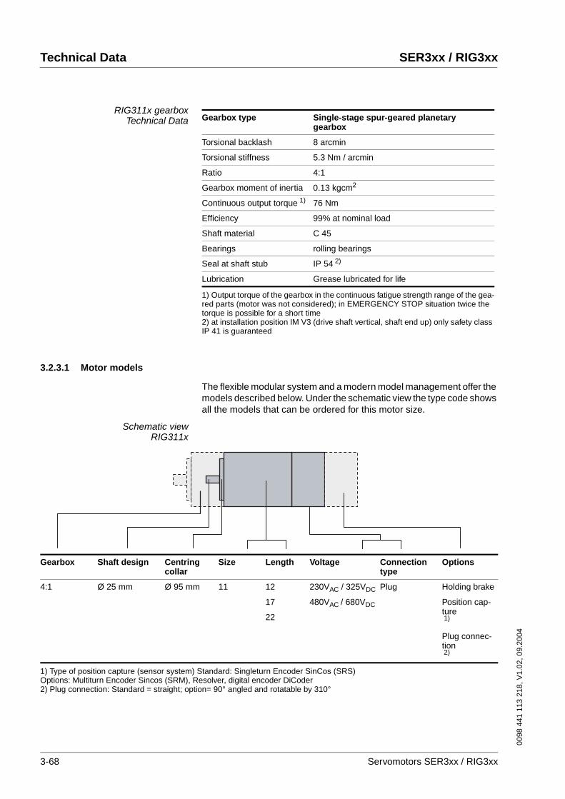
Technical Data SER3xx / RIG3xx
0098
441
113
218
, V1.
02, 0
9.20
04
RIG311x gearboxTechnical Data
3.2.3.1 Motor models
The flexible modular system and a modern model management offer the models described below. Under the schematic view the type code shows all the models that can be ordered for this motor size.
Schematic viewRIG311x
Gearbox type Single-stage spur-geared planetary gearbox
Torsional backlash 8 arcmin
Torsional stiffness 5.3 Nm / arcmin
Ratio 4:1
Gearbox moment of inertia 0.13 kgcm2
Continuous output torque 1)
1) Output torque of the gearbox in the continuous fatigue strength range of the gea-red parts (motor was not considered); in EMERGENCY STOP situation twice the torque is possible for a short time
76 Nm
Efficiency 99% at nominal load
Shaft material C 45
Bearings rolling bearings
Seal at shaft stub IP 54 2)
2) at installation position IM V3 (drive shaft vertical, shaft end up) only safety class IP 41 is guaranteed
Lubrication Grease lubricated for life
Gearbox Shaft design Centring collar
Size Length Voltage Connectiontype
Options
4:1 Ø 25 mm Ø 95 mm 11 12
17
22
230VAC / 325VDC
480VAC / 680VDC
Plug Holding brake
Position cap-ture1)
Plug connec-tion2)
1) Type of position capture (sensor system) Standard: Singleturn Encoder SinCos (SRS)Options: Multiturn Encoder Sincos (SRM), Resolver, digital encoder DiCoder2) Plug connection: Standard = straight; option= 90° angled and rotatable by 310°
3-68 Servomotors SER3xx / RIG3xx
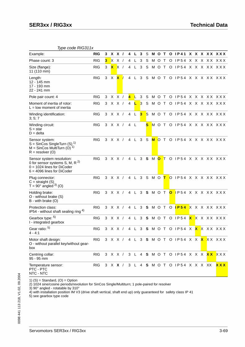
0098
441
113
218
, V1.
02, 0
9.20
04
SER3xx / RIG3xx Technical Data
Type code RIG311xExample: RIG 3 X X / 4 L 3 S M O T O I P 4 1 X X X X X X X X
Phase count: 3 RIG 3 X X / 4 L 3 S M O T O I P 5 4 X X X X X X X X
Size (flange):11 (110 mm)
RIG 3 X X / 4 L 3 S M O T O I P 5 4 X X X X X X X X
Length:12 - 145 mm17 - 193 mm22 - 241 mm
RIG 3 X X / 4 L 3 S M O T O I P 5 4 X X X X X X X X
Pole pair count: 4 RIG 3 X X / 4 L 3 S M O T O I P 5 4 X X X X X X X X
Moment of inertia of rotor:L = low moment of inertia
RIG 3 X X / 4 L 3 S M O T O I P 5 4 X X X X X X X X
Winding identification:3; 5; 7
RIG 3 X X / 4 L 3 S M O T O I P 5 4 X X X X X X X X
Winding circuit:S = starD = delta
RIG 3 X X / 4 L S M O T O I P 5 4 X X X X X X X X
Sensor system:S = SinCos SingleTurn (S) 1)
M = SinCos MultiTurn (O) 1)
R = resolver (O)
RIG 3 X X / 4 L 3 S M O T O I P 5 4 X X X X X X X X
Sensor system resolution:0 for sensor systems S, M, R 2)
0 = 1024 lines for DiCoder6 = 4096 lines for DiCoder
RIG 3 X X / 4 L 3 S M O T O I P 5 4 X X X X X X X X
Plug connector:C = straight (S)T = 90° angled 3) (O)
RIG 3 X X / 4 L 3 S M O T O I P 5 4 X X X X X X X X
Holding brake:O - without brake (S)B - with brake (O)
RIG 3 X X / 4 L 3 S M O T O I P 5 4 X X X X X X X X
Protection class:IP54 - without shaft sealing ring 4)
RIG 3 X X / 4 L 3 S M O T O I P 5 4 X X X X X X X X
Gearbox type: 5)
I - integrated gearbox RIG 3 X X / 4 L 3 S M O T O I P 5 4 X X X X X X X X
Gear ratio: 5)
4 - 4:1RIG 3 X X / 4 L 3 S M O T O I P 5 4 X X X X X X X X
Motor shaft design:O - without parallel key/without gear-box
RIG 3 X X / 4 L 3 S M O T O I P 5 4 X X X X X X X X
Centring collar:95 - 95 mm
RIG 3 X X / 3 L 4 S M O T O I P 5 4 X X X X X X X X
Temperature sensor:PTC - PTCNTC - NTC
RIG 3 X X / 3 L 4 S M O T O I P 5 4 X X X XX X X X
1) (S) = Standard, (O) = Option2) 1024 sine/cosine periods/revolution for SinCos Single/Multiturn; 1 pole-paired for resolver3) 90° angled - rotatable by 310°4) with installation position IM V3 (drive shaft vertical, shaft end up) only guaranteed for safety class IP 415) see gearbox type code
Servomotors SER3xx / RIG3xx 3-69

Technical Data SER3xx / RIG3xx
0098
441
113
218
, V1.
02, 0
9.20
04
3.2.3.2 Dimensional drawing
Dimensions RIG311x
3.2.3.3 Options
Holding brake
Holding brake RIG311x The holding brake is an electromagnetic spring-pressure brake. It holds the motor axis after the motor current is switched off, including after po-wer failure and EMERGENCY STOP. A holding brake is required parti-cularly for torque loads caused by weight forces, such as occur with Z-axes in handling technology. The control is described in Chapter 4.3.2 “Electrical control of the holding brake“.
Signal receptacleMotor receptacle 8-pin
*
ATTENTION!
The hole in shaft end must be open for pressure equalization (Normal atmospheric pressure).
rotatabelrotatabel
rotatabel
rotatabel
stop
RIG 31112 RIG 31117 RIG 31122
L (length) [mm] 145 193 241
LB (length with brake) [mm] 211 259 307
WARNING!Wear or high temperature will cause loss of braking power.
Incorrect use of the holding brake causes accelerated wear and loss of braking power. Heat reduces the holding torque.
• Do not use the brake as a service brake.
• At operating temperatures over 80°C do not exceed a maximum of 50% of the specified holding torque when using the brake.
Failure to follow these instructions can result in death or serious injury.
Technical Data
Nominal voltage [DC] 24 V ±10%
Holding torque 16 Nm
Electrical pick-up power 28 W
Moment of inertia 0.35 kgcm2
Make time (brake ventilation) 60 ms
Break time (close brake) 30 ms
Mass approx. 3 kg
3-70 Servomotors SER3xx / RIG3xx
0098
441
113
218
, V1.
02, 0
9.20
04
SER3xx / RIG3xx Technical Data
Position capture
SinCos Multiturn sensor system(SRM50)
This sensor system measures an absolute value within 4096 revolutions after being switched on and continues to count incrementally from this point.
Resolver sensor system This sensor system is a very robust absolute system. Absolute position capture is possible within one revolution.
Digital encoder sensor system(DiCoder)
This sensor system is an optical (incremental) system.
The data for the sensor systems can be found in Chapter 3.1.1.1 “Posi-tion capture (sensor)“.
Servomotors SER3xx / RIG3xx 3-71
Technical Data SER3xx / RIG3xx
0098
441
113
218
, V1.
02, 0
9.20
04
3.3 PLE and PLS gearbox
The AC servomotors of the SER3xx series can be combined with the ge-arboxes that we have selected as standard for your applications
The configurations options of the motors with the gearboxes and the re-sulting possible torques can be found with the corresponding motor de-scriptions. The common properties of the gearboxes and the size and dimensions are described here.
PLE gearbox The PLE planetary gearbox series is the economy alternative to the PLS planetary gearbox series. They have been developed for applications that do not require extremely low torsional play.
• low torsional play
• high output torques
• patented PCS® (precision connection)
• high efficiency (96%, depending on ratio)
• 22 ratios i=3,...,512
• low noise
• high quality (ISO 9001)
• any desired installation position
• simple motor attachment
• lubricated for life
PLS gearbox Our customers' requirements are reflected by innovative solutions in our products. The PLS series represents absolute precision and can be found in almost all aspects of mechanical engineering.
• extremely low torsional play (<3’)
• high output torques
• patented NIEC® as option (optimised for high speed)
• patented PCS® (precision connection)
• high efficiency (98%, depending on ratio)
• honed gear teeth
• 14 ratios i=3,...,100
• low noise (<65dBA)
• high quality (ISO 9001)
• any desired installation position
• simple motor attachment
• lubricated for life
3-72 Servomotors SER3xx / RIG3xx
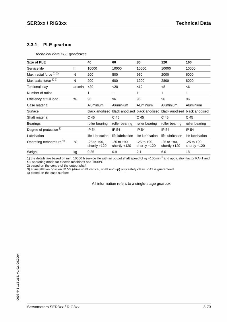
0098
441
113
218
, V1.
02, 0
9.20
04
SER3xx / RIG3xx Technical Data
3.3.1 PLE gearbox
Technical data PLE gearboxes
All information refers to a single-stage gearbox.
Size of PLE 40 60 80 120 160
Service life h 10000 10000 10000 10000 10000
Max. radial force 1) 2) N 200 500 950 2000 6000
Max. axial force 1) 2) N 200 600 1200 2800 8000
Torsional play arcmin <30 <20 <12 <8 <6
Number of ratios 1 1 1 1 1
Efficiency at full load % 96 96 96 96 96
Case material Aluminium Aluminium Aluminium Aluminium Aluminium
Surface black anodised black anodised black anodised black anodised black anodised
Shaft material C 45 C 45 C 45 C 45 C 45
Bearings roller bearing roller bearing roller bearing roller bearing roller bearing
Degree of protection 3) IP 54 IP 54 IP 54 IP 54 IP 54
Lubrication life lubrication life lubrication life lubrication life lubrication life lubrication
Operating temperature 4) °C -25 to +90, shortly +120
-25 to +90, shortly +120
-25 to +90, shortly +120
-25 to +90, shortly +120
-25 to +90, shortly +120
Weight kg 0.35 0.9 2.1 6.0 18
1) the details are based on min. 10000 h service life with an output shaft speed of n2 =100min-1 and application factor KA=1 and S1 operating mode for electric machines and T=30°C2) based on the centre of the output shaft3) at installation position IM V3 (drive shaft vertical, shaft end up) only safety class IP 41 is guaranteed4) based on the case surface
Servomotors SER3xx / RIG3xx 3-73
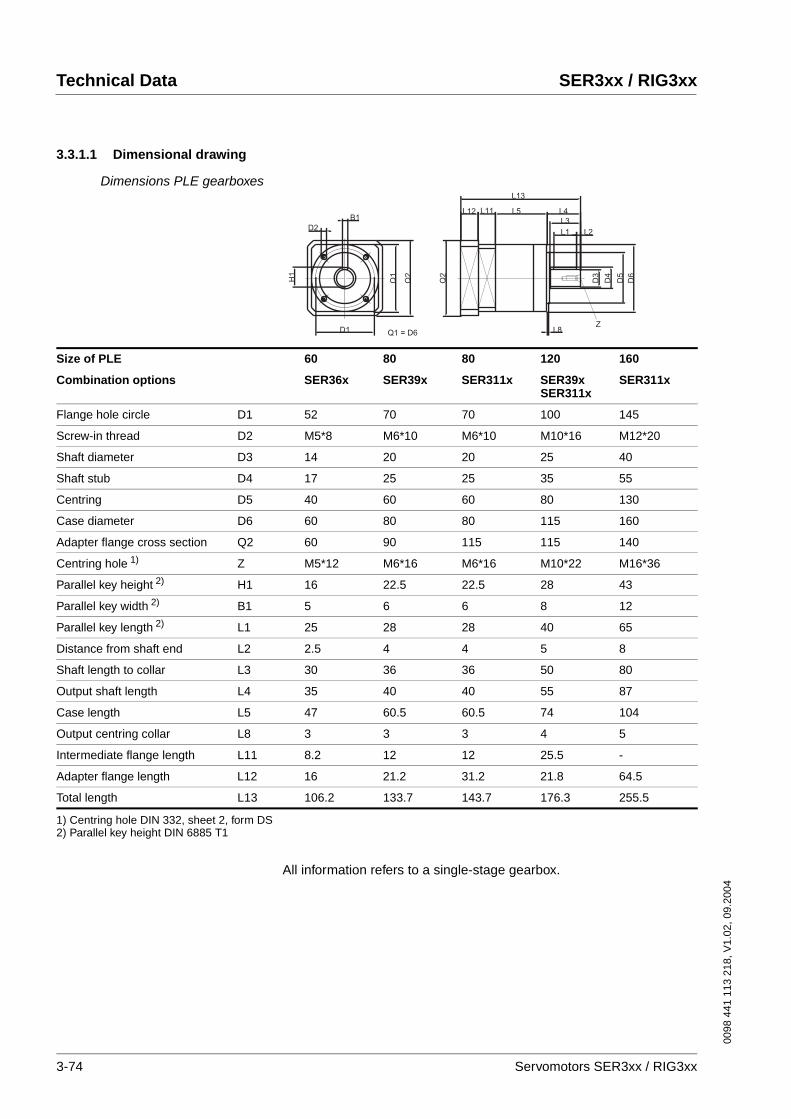
Technical Data SER3xx / RIG3xx
0098
441
113
218
, V1.
02, 0
9.20
04
3.3.1.1 Dimensional drawing
Dimensions PLE gearboxes
All information refers to a single-stage gearbox.
D3
D4
D5
D6
L1 L2
L3
L4L5L11L12
L13
L8
Q2
D1
D2
H1
B1
Q1
Q2
Q1 = D6Z
Size of PLE 60 80 80 120 160
Combination options SER36x SER39x SER311x SER39x SER311x
SER311x
Flange hole circle D1 52 70 70 100 145
Screw-in thread D2 M5*8 M6*10 M6*10 M10*16 M12*20
Shaft diameter D3 14 20 20 25 40
Shaft stub D4 17 25 25 35 55
Centring D5 40 60 60 80 130
Case diameter D6 60 80 80 115 160
Adapter flange cross section Q2 60 90 115 115 140
Centring hole 1) Z M5*12 M6*16 M6*16 M10*22 M16*36
Parallel key height 2) H1 16 22.5 22.5 28 43
Parallel key width 2) B1 5 6 6 8 12
Parallel key length 2) L1 25 28 28 40 65
Distance from shaft end L2 2.5 4 4 5 8
Shaft length to collar L3 30 36 36 50 80
Output shaft length L4 35 40 40 55 87
Case length L5 47 60.5 60.5 74 104
Output centring collar L8 3 3 3 4 5
Intermediate flange length L11 8.2 12 12 25.5 -
Adapter flange length L12 16 21.2 31.2 21.8 64.5
Total length L13 106.2 133.7 143.7 176.3 255.5
1) Centring hole DIN 332, sheet 2, form DS2) Parallel key height DIN 6885 T1
3-74 Servomotors SER3xx / RIG3xx
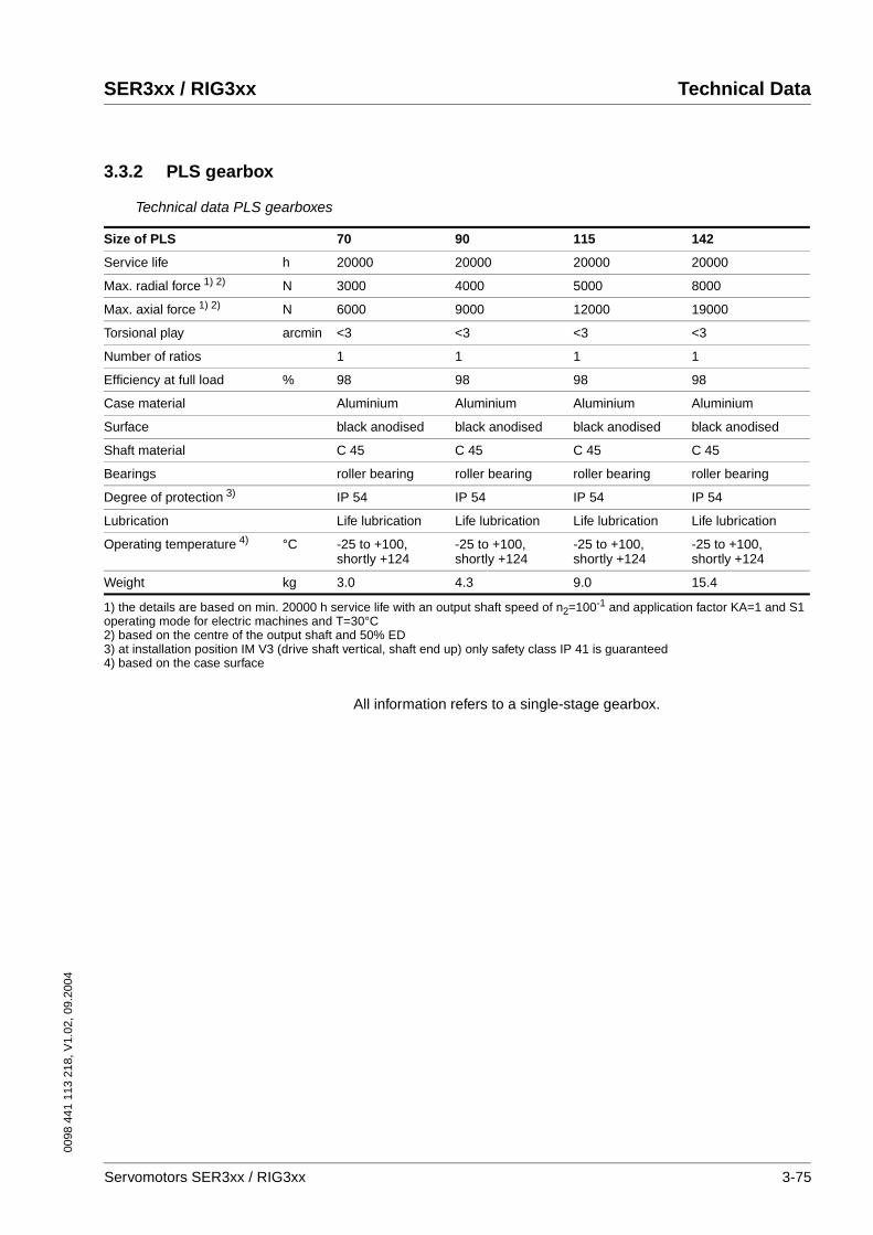
0098
441
113
218
, V1.
02, 0
9.20
04
SER3xx / RIG3xx Technical Data
3.3.2 PLS gearbox
Technical data PLS gearboxes
All information refers to a single-stage gearbox.
Size of PLS 70 90 115 142
Service life h 20000 20000 20000 20000
Max. radial force 1) 2) N 3000 4000 5000 8000
Max. axial force 1) 2) N 6000 9000 12000 19000
Torsional play arcmin <3 <3 <3 <3
Number of ratios 1 1 1 1
Efficiency at full load % 98 98 98 98
Case material Aluminium Aluminium Aluminium Aluminium
Surface black anodised black anodised black anodised black anodised
Shaft material C 45 C 45 C 45 C 45
Bearings roller bearing roller bearing roller bearing roller bearing
Degree of protection 3) IP 54 IP 54 IP 54 IP 54
Lubrication Life lubrication Life lubrication Life lubrication Life lubrication
Operating temperature 4) °C -25 to +100, shortly +124
-25 to +100, shortly +124
-25 to +100, shortly +124
-25 to +100, shortly +124
Weight kg 3.0 4.3 9.0 15.4
1) the details are based on min. 20000 h service life with an output shaft speed of n2=100-1 and application factor KA=1 and S1 operating mode for electric machines and T=30°C2) based on the centre of the output shaft and 50% ED3) at installation position IM V3 (drive shaft vertical, shaft end up) only safety class IP 41 is guaranteed4) based on the case surface
Servomotors SER3xx / RIG3xx 3-75
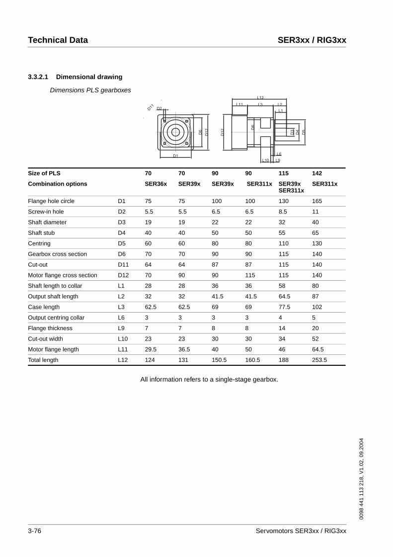
Technical Data SER3xx / RIG3xx
0098
441
113
218
, V1.
02, 0
9.20
04
3.3.2.1 Dimensional drawing
Dimensions PLS gearboxes
All information refers to a single-stage gearbox.
D1
D2
D3
D4
D5
L1
L2
L6
L9L10
L3
L12
L11
D1
2 D6
D6
D1
2
D11
Size of PLS 70 70 90 90 115 142
Combination options SER36x SER39x SER39x SER311x SER39x SER311x
SER311x
Flange hole circle D1 75 75 100 100 130 165
Screw-in hole D2 5.5 5.5 6.5 6.5 8.5 11
Shaft diameter D3 19 19 22 22 32 40
Shaft stub D4 40 40 50 50 55 65
Centring D5 60 60 80 80 110 130
Gearbox cross section D6 70 70 90 90 115 140
Cut-out D11 64 64 87 87 115 140
Motor flange cross section D12 70 90 90 115 115 140
Shaft length to collar L1 28 28 36 36 58 80
Output shaft length L2 32 32 41.5 41.5 64.5 87
Case length L3 62.5 62.5 69 69 77.5 102
Output centring collar L6 3 3 3 3 4 5
Flange thickness L9 7 7 8 8 14 20
Cut-out width L10 23 23 30 30 34 52
Motor flange length L11 29.5 36.5 40 50 46 64.5
Total length L12 124 131 150.5 160.5 188 253.5
3-76 Servomotors SER3xx / RIG3xx
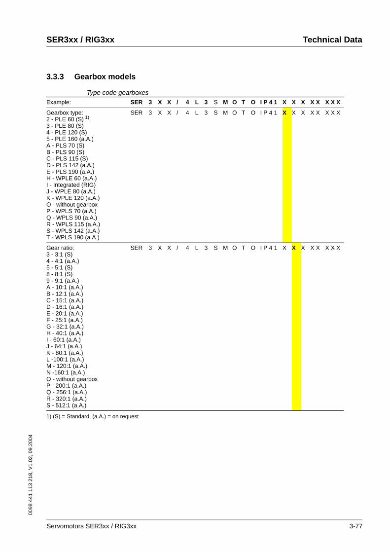
0098
441
113
218
, V1.
02, 0
9.20
04
SER3xx / RIG3xx Technical Data
3.3.3 Gearbox models
Type code gearboxesExample: SER 3 X X / 4 L 3 S M O T O I P 4 1 X X X X X X X X
Gearbox type: 2 - PLE 60 (S) 1)
3 - PLE 80 (S)4 - PLE 120 (S)5 - PLE 160 (a.A.)A - PLS 70 (S)B - PLS 90 (S)C - PLS 115 (S)D - PLS 142 (a.A.)E - PLS 190 (a.A.)H - WPLE 60 (a.A.)I - Integrated (RIG)J - WPLE 80 (a.A.)K - WPLE 120 (a.A.)O - without gearboxP - WPLS 70 (a.A.)Q - WPLS 90 (a.A.)R - WPLS 115 (a.A.)S - WPLS 142 (a.A.)T - WPLS 190 (a.A.)
SER 3 X X / 4 L 3 S M O T O I P 4 1 X X X X X X X X
Gear ratio: 3 - 3:1 (S)4 - 4:1 (a.A.)5 - 5:1 (S)8 - 8:1 (S)9 - 9:1 (a.A.) A - 10:1 (a.A.)B - 12:1 (a.A.)C - 15:1 (a.A.)D - 16:1 (a.A.)E - 20:1 (a.A.)F - 25:1 (a.A.)G - 32:1 (a.A.)H - 40:1 (a.A.)I - 60:1 (a.A.)J - 64:1 (a.A.)K - 80:1 (a.A.)L -100:1 (a.A.)M - 120:1 (a.A.)N -160:1 (a.A.)O - without gearboxP - 200:1 (a.A.)Q - 256:1 (a.A.)R - 320:1 (a.A.)S - 512:1 (a.A.)
SER 3 X X / 4 L 3 S M O T O I P 4 1 X X X X X X X X
1) (S) = Standard, (a.A.) = on request
Servomotors SER3xx / RIG3xx 3-77
Technical Data SER3xx / RIG3xx
0098
441
113
218
, V1.
02, 0
9.20
04
3-78 Servomotors SER3xx / RIG3xx

0098
441
113
218
, V1.
02, 0
9.20
04
SER3xx / RIG3xx Installation
4 Installation
DANGER!Electric shock, fire or explosion
• Only technicians who are familiar with and understand the con-tents of this manual and the other relevant manuals are authori-sed to work on and with this drive system.
• Before working on the drive system:
– Switch off power to all terminals.
– Place a sign "DO NOT SWITCH ON" on the switch and lock to prevent its being switched on.
– Allow the DC bus capacitors to discharge (see power ampli-fier manual).
– Check that there is no power.
• Do not short-circuit DC bus or touch unshielded components or screws of the terminals under voltage.
• Install all covers and close the housing doors before applying power.
• The motor generates voltage when the shaft is rotated. Lock the shaft of the motor to prevent rotation before starting work on the drive system.
• AC voltages may jump over unused wires in the motor cable. Isolate unused wires at both ends of the motor cable.
• The system manufacturer is responsible for compliance with all applicable regulations relevant to earthing the drive system. Extend the earth through the motor cable with an additional earth at the motor housing.
Failure to follow these instructions will result in death or serious injury.
WARNING!Strong electromagnetic fields may cause injury and interfe-rence.
Motors can generate strong localised electrical and magnetic fields. This can cause interference in sensitive devices.
• Keep persons with pacemakers clear of the motor.
• Do not place any sensitive devices near the motor.Neglect can result in an accident or damage to the system
Servomotors SER3xx / RIG3xx 4-1
Installation SER3xx / RIG3xx
0098
441
113
218
, V1.
02, 0
9.20
04
4.1 Before assembly
• Read this manual carefully, particularly the chapter on safety and follow all safety instructions. Familiarise yourself with the power controller manual also. This will minimise the accident risk and pre-vent damage to the drive and to your system.
• Before assembly obtain all required tools, instruments, testing aids and equipment.
• Before assembly check the drive system for visible damage caused by incorrect transport or storage. Damaged drive systems must not be installed to prevent any danger to persons or the machine.
• Check the name plate to ensure that the motor is actually suitable for the intended application.
• Make sure that the required environmental conditions for operation will be maintained.
• The shaft ends of the SER and RIG servomotors are coated to pre-vent corrosion. The coating must be removed with standard indus-trial cleaners and a soft cloth. Follow the safety instructions of the manufacturer of the cleaning agent. Avoid direct skin and sealing material contact with the preserving agent or the industrial cleaner. Make sure that there is no corrosion damage to the motor flange or the shaft ends.
• Make sure that the attachment for the motor flange is stable, clean, free of chips and does not oscillate or vibrate. Check that the sys-tem side conforms with all dimensions and tolerances.
• With a motor with a holding brake check that the brake reaches the holding torque specified in the data sheet.
4.2 Installation of the motor
WARNING!Electrostatic discharges may cause injury and damage to the drive.
In rare cases electrostatic discharges (ESD) at the shaft caused by a fault in the sensor system may cause unexpected motions of the drive and damage the system.
• Use conductive components (e.g. antistatic belts) or other sui-table measures for preventing charge separation by motion
Failure to follow these instructions can result in death or serious injury.
4-2 Servomotors SER3xx / RIG3xx
0098
441
113
218
, V1.
02, 0
9.20
04
SER3xx / RIG3xx Installation
CAUTION!Failure of the drive by mechanical damage.
If the maximum allowable forces on the shaft are exceeded, this will result in accelerated bearing wear or shaft breakage.
• Do not exceed the maximum allowable axial and radial forces.
• Protect the shaft against impact.
• Do not exceed the maximum allowable axial force even when pressing on output components.
Failure to follow these instructions can result in injury or equipment damage.
CAUTION!The gearbox can be destroyed by overload.
Exceeding the allowable torques will cause accelerated wear, shaft breakage or blocking.
• Do not exceed the peak gearbox torque in any operating status.
• Limit the motor torque if there is a danger of destruction of the gearbox by peak torques.
• Limit the torque in short-time operation (e.g. in an EMER-GENCY STOP situation) to twice the continuous gearbox out-put torque MdG
Failure to follow these instructions can result in injury or equipment damage.
CAUTION!Hot surfaces can cause burns and damage to system compo-nents!
The drive temperature can exceed 100°C in some conditions.
• Avoid contact with the hot drive.
• Do not place heat-sensitive components in the immediate vici-nity of the drive.
• Follow the actions described for heat dissipation.
• Check the temperature of the drive during the test run.Failure to follow these instructions can result in injury or equipment damage.
WARNING!Danger of injury and damage to system components by loss of degree of protection
Foreign bodies, deposits or humidity can cause unexpected device responses.
• Prevent any foreign bodies from entering the terminal unit.
• Check that seals and cable glands are correctly seated.Neglect can result in an accident or damage to the system
Servomotors SER3xx / RIG3xx 4-3
Installation SER3xx / RIG3xx
0098
441
113
218
, V1.
02, 0
9.20
04
Installation position Our motors can be installed in any desired position; under DIN EN 60034-7 the following installation positions are defined and approved:
• IM B5 drive shaft horizontal
• IM V1 drive shaft vertical, shaft end down
• IM V3 drive shaft vertical, shaft end up
Installation When attaching the motor to fastening flange, make sure that the motor is carefully aligned and has an even contact. Carefully tighten all faste-ning screws to the specified torque and ensure that there is no tension.
Attaching output components Attach output components such as pulleys, clutch etc. with suitable equipment and tools. The maximum effective axial and radial forces on the shaft must not exceed the values specified for the maximum shaft load. If the output component is incorrectly attached, the sensor for po-sition capture may be damaged.
Follow the installation directions of the manufacturer of the output com-ponent. Both motor and output component must be precisely aligned both axially and radially. Neglect will result in noisy running, bearing da-mage and fast wear.
WARNING!Unexpected motion and destruction of the drive may cause in-jury.
If drives are installed with the shaft end up (IM V3) and liquid collects at the shaft end over an extended period, it may enter the drive and damage it.
• Prevent liquid from collecting at the shaft end for extended peri-ods.
Failure to follow these instructions can result in death or serious injury.
4-4 Servomotors SER3xx / RIG3xx
0098
441
113
218
, V1.
02, 0
9.20
04
SER3xx / RIG3xx Installation
4.3 Electrical installation
4.3.1 Connecting the motor
Our motors are not designed for direct connection to mains power; they must be operated with a suitable power amplifier.
Motor and sensor system plugs can be removed and reconnected under power.
Fully finished motor and sensor system connections in many different lengths are available for our drive solutions. Contact your dealer.
WARNING!Unexpected motion may cause injury and damage to the sys-tem
Drives can make unexpected movements if incorrectly connected or because of other faults.
• Operate the motor with approved power amplifiers only. Even if power amplifiers are similar, different adjustment of the sensor system may be a source of danger.
• Check the wiring. Compatibility is not assured even with mat-ching connectors for power connections and sensor system from a different manufacturer.
• Only start the system if there are no persons or materials in the danger zone and the system can be operated safely.
• Conduct test runs first without coupled loads.
• Do not touch the shaft of the motor or the attached output com-ponents.
Failure to follow these instructions can result in death or serious injury.
WARNING!Interference with signals and devices may cause injury
Distorted signals can cause unexpected device responses.
• Install the wiring in accordance with the EMC requirements.
• Check compliance with the EMC requirements, particularly in an environment subject to strong interference.
Failure to follow these instructions can result in death or serious injury.
CAUTION!Overheating the plug may cause fire.
The power plug connector may overheat and fuse contacts by ar-cing if the plug is not correctly connected and the cap is not tightly screwed in place.
• Make sure that plug is correctly connected and the plug cap is tight.
Failure to follow these instructions can result in injury or equipment damage.
Servomotors SER3xx / RIG3xx 4-5
Installation SER3xx / RIG3xx
0098
441
113
218
, V1.
02, 0
9.20
04
EMC requirement:Run motor wiring alone
When planning the wiring make sure that the motor wiring is laid sepa-rately. It must never by laid in a conduit together with power, control or sensor lines or fastened parallel with wiring clamps.
EMC requirement:motor and motor sensor wiring
Motor leads and motor sensor cables are especially critical signal lines. Use the cables recommended by your local representative. They must be tested for EMC safety and must be suitable for trailing cables.
The motor wiring and the motor sensor wiring on the drive solution must be laid out over a wide area with low resistance on the unit, the switch cabinet output and on the motor.
� Lay out motor and motor sensor wiring without interruption (do not install switch components) from the motor and sensor to the unit.If a line has to be interrupted, shielded connections and metal casing must be used to prevent interference.
� Lay the motor wiring at least 20 cm from the signal wiring.If the distance is less than this, the motor cable and signal cables must be separated by grounded screening plates.
� For long lines bonding conductors with a suitable cross section must be used
EMC requirement:Mains and motor connection
Great care is required when connecting the mains power and the motor to the power controller, because the danger of uncontrolled overcoup-ling is greatest here.
� Lay mains and motor wiring well apart(> 25 cm).
� Keep motor wiring as short as possible.
� Keep unshielded leads of the motor wiring (e.g. U,V,W) on the device and motor as short as possible.
This is the only way to prevent the formation of active and passive an-tennas.
EMC requirement:Earth band
Connect the motor to earth with an earth band > 8mm2 to ensure correct function without interference.
fully fabricatedMotor and sensor system wiring
Use only the fully fabricated and tested connection lines that we supply for the motor connection and to connect the sensor system. They are op-timally designed for these drive solutions.
Place the sleeve of the motor wiring on the motor plug connector and tighten the screw cap. Proceed in the same way with the sensor system connection line. Connect the motor wiring and the sensor system wiring with the power controller as specified by the circuit diagram of the power controller. If your motor is fitted with a holding brake, please follow the in-structions on 4.3.2 “Electrical control of the holding brake“.
PE conductor connection For safety reasons a redundant PE conductor connection is recommen-ded.
4-6 Servomotors SER3xx / RIG3xx
0098
441
113
218
, V1.
02, 0
9.20
04
SER3xx / RIG3xx Installation
4.3.2 Electrical control of the holding brake
A motor with a holding brake requires appropriate control logic which re-leases the brake exactly at the start of a rotary motion and fixed the mo-tor axis when the motor is stopped.
Control circuit Use a suitable holding brake controller, such as the Berger Lahr TLHBC. The current of the brake voltage must be reduced after approximately 100 ms, otherwise the additional heating will make it impossible to gua-rantee the published torque characteristics. The holding brake controller must have safe electrical isolation of the brake power supply and comply with EMC standard DIN EN 8008-3.
Special feature of SER36xCAUTION!Brake malfunction!
The brake cannot release because of incorrect voltage.
• Check the voltage polarity. If the voltage polarity is incorrect the brake will not release.
• Check the voltage. The brake may close again if the voltage exceeds the specified value.
Failure to follow these instructions can result in injury or equipment damage.
Servomotors SER3xx / RIG3xx 4-7

Installation SER3xx / RIG3xx
0098
441
113
218
, V1.
02, 0
9.20
04
4.4 Plugs and plug assignments
Motor connection
Manufacturer: Intercontec, power plug connector 8-pole, BEGA089NN0000 0002 000
PIN Assignments
1 U
2 PE
3 W
4 V
A brake +
B brake -
C not assigned
D not assigned
A
B
C
D
1
4
3
A
A
MotorgehäuseMotor housing
4-8 Servomotors SER3xx / RIG3xx

0098
441
113
218
, V1.
02, 0
9.20
04
SER3xx / RIG3xx Installation
Sensor connectionSinCos Encoder
Sensor plug SinCos Encoder (SINGLE-TURN and MULTI-TURN)
Manufacturer: Intercontec, signal plug connector 12-pole, AEGA052NN0000 1250 000
PTC: S+M, Model B59135-M155-A70NTC: S+M, Model B57227
PIN Assignments
1 Temperature sensor PTC/NTC
2 Temperature sensor PTC/NTC
3 not assigned
4 REF SIN
5 REF COS
6 Data+ RS 485
7 Data- RS 485
8 + SIN
9 + COS
10 Us 7-12 V
11 GND
12 not assigned
A
MotorgehäuseMotor housing
11
9
6
5
7
12
8
34
10
1
2P
A
Servomotors SER3xx / RIG3xx 4-9
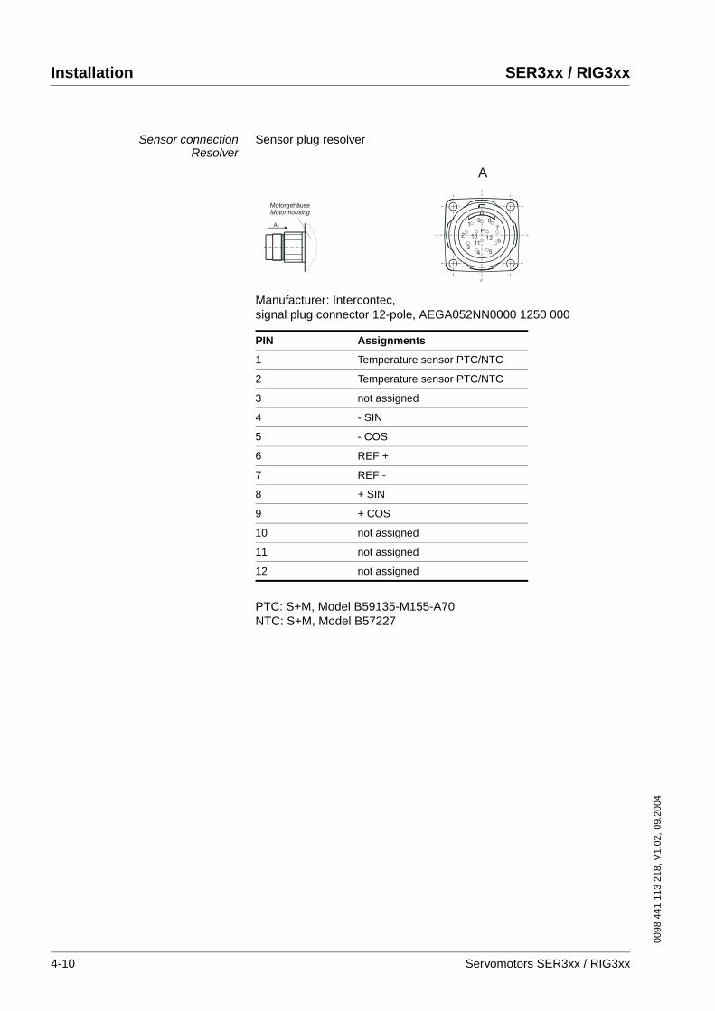
Installation SER3xx / RIG3xx
0098
441
113
218
, V1.
02, 0
9.20
04
Sensor connectionResolver
Sensor plug resolver
Manufacturer: Intercontec, signal plug connector 12-pole, AEGA052NN0000 1250 000
PTC: S+M, Model B59135-M155-A70NTC: S+M, Model B57227
PIN Assignments
1 Temperature sensor PTC/NTC
2 Temperature sensor PTC/NTC
3 not assigned
4 - SIN
5 - COS
6 REF +
7 REF -
8 + SIN
9 + COS
10 not assigned
11 not assigned
12 not assigned
A
MotorgehäuseMotor housing
11
9
6
5
7
12
8
34
10
1
2P
A
4-10 Servomotors SER3xx / RIG3xx
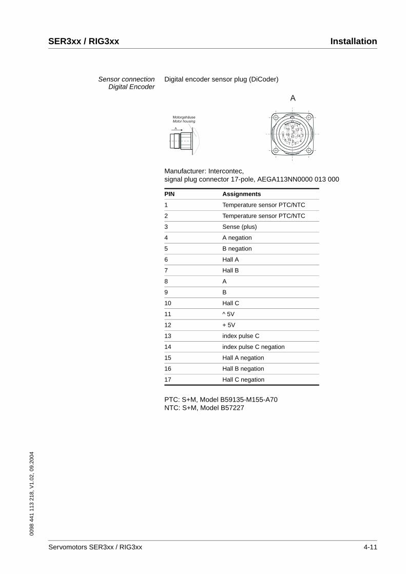
0098
441
113
218
, V1.
02, 0
9.20
04
SER3xx / RIG3xx Installation
Sensor connectionDigital Encoder
Digital encoder sensor plug (DiCoder)
Manufacturer: Intercontec, signal plug connector 17-pole, AEGA113NN0000 013 000
PTC: S+M, Model B59135-M155-A70NTC: S+M, Model B57227
PIN Assignments
1 Temperature sensor PTC/NTC
2 Temperature sensor PTC/NTC
3 Sense (plus)
4 A negation
5 B negation
6 Hall A
7 Hall B
8 A
9 B
10 Hall C
11 ^ 5V
12 + 5V
13 index pulse C
14 index pulse C negation
15 Hall A negation
16 Hall B negation
17 Hall C negation
A
MotorgehäuseMotor housing
A
12
3
45
67
8
9
1011
1213
1415
1617
E
Servomotors SER3xx / RIG3xx 4-11
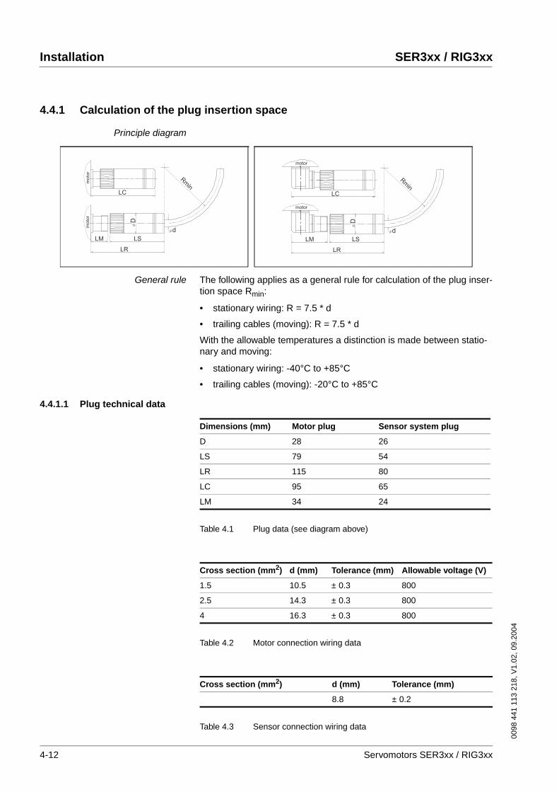
Installation SER3xx / RIG3xx
0098
441
113
218
, V1.
02, 0
9.20
04
4.4.1 Calculation of the plug insertion space
Principle diagram
General rule The following applies as a general rule for calculation of the plug inser-tion space Rmin:
• stationary wiring: R = 7.5 * d
• trailing cables (moving): R = 7.5 * d
With the allowable temperatures a distinction is made between statio-nary and moving:
• stationary wiring: -40°C to +85°C
• trailing cables (moving): -20°C to +85°C
4.4.1.1 Plug technical data
Table 4.1 Plug data (see diagram above)
Table 4.2 Motor connection wiring data
Table 4.3 Sensor connection wiring data
mo
tor
mo
tor
Rm
in
LM LS
LR
LC
D
d
motor
Rm
in
LM LS
LR
LC
D
d
motor
Dimensions (mm) Motor plug Sensor system plug
D 28 26
LS 79 54
LR 115 80
LC 95 65
LM 34 24
Cross section (mm2) d (mm) Tolerance (mm) Allowable voltage (V)
1.5 10.5 ± 0.3 800
2.5 14.3 ± 0.3 800
4 16.3 ± 0.3 800
Cross section (mm2) d (mm) Tolerance (mm)
8.8 ± 0.2
4-12 Servomotors SER3xx / RIG3xx
0098
441
113
218
, V1.
02, 0
9.20
04
SER3xx / RIG3xx Commissioning
5 Commissioning
5.1 Preparing for commissioning
Before commissioning check
� the correct mechanical installation: take particular note of correctly installed screws at the flange and tension-free alignment of the motor.
� the correctly conducted electrical installation: in particular check the PE conductor connections and earth connections. Make sure that all connections on the motor and to the power controller are cor-rectly made and connected and that cable fasteners are tight.
� the correct isolation of unused reserve wires: unused lines must be correctly isolated at both ends, because induction currents may also flow in unused wires in drive systems.
� the guards to prevent contact: the appropriate guards must be installed to prevent contact with electrical and mechanical or moving parts.
� the environmental and operation conditions: make sure that the specified environmental conditions are maintained and that the
DANGER!Electric shock, fire or explosion
• Only technicians who are familiar with and understand the con-tents of this manual and the other relevant manuals are authori-sed to work on and with this drive system.
• Before working on the drive system:
– Switch off power to all terminals.
– Place a sign "DO NOT SWITCH ON" on the switch and lock to prevent its being switched on.
– Allow the DC bus capacitors to discharge (see power ampli-fier manual).
– Check that there is no power.
• Do not short-circuit DC bus or touch unshielded components or screws of the terminals under voltage.
• Install all covers and close the housing doors before applying power.
• The motor generates voltage when the shaft is rotated. Lock the shaft of the motor to prevent rotation before starting work on the drive system.
• AC voltages may jump over unused wires in the motor cable. Isolate unused wires at both ends of the motor cable.
• The system manufacturer is responsible for compliance with all applicable regulations relevant to earthing the drive system. Extend the earth through the motor cable with an additional earth at the motor housing.
Failure to follow these instructions will result in death or serious injury.
Servomotors SER3xx / RIG3xx 5-1
Commissioning SER3xx / RIG3xx
0098
441
113
218
, V1.
02, 0
9.20
04
drive solution matches the operating conditions as specified on the name plate.
� the output components: check that the output components, which may be already installed, are balanced and precisely aligned.
� the parallel key at the shaft end of the motor: if you have a motor with a parallel key groove and parallel key, the parallel key must not be inserted when commissioning without output component or it must be appropriately secured.
� the function of the holding brake: check that the holding torque of the brake as specified in the data sheet is reached. Make sure that the holding brake is ventilated after applying the brake voltage.
5.2 Running commissioning
WARNING!Unexpected motion may cause injury and damage to the sys-tem
Drives can make unexpected movements if incorrectly connected or because of other faults.
• Operate the motor with approved power amplifiers only. Even if power amplifiers are similar, different adjustment of the sensor system may be a source of danger.
• Check the wiring. Compatibility is not assured even with mat-ching connectors for power connections and sensor system from a different manufacturer.
• Only start the system if there are no persons or materials in the danger zone and the system can be operated safely.
• Conduct test runs first without coupled loads.
• Do not touch the shaft of the motor or the attached output com-ponents.
Failure to follow these instructions can result in death or serious injury.
WARNING!Rotating parts may cause injury and damage to the system.
Rotating parts may cause injuries and may catch clothing or hair. Loose parts or parts that are unbalanced may be thrown clear.
• After installation check all rotating parts (parallel keys, clutch, ..).
• Use a guard as protection against rotating parts.Failure to follow these instructions can result in death or serious injury.
5-2 Servomotors SER3xx / RIG3xx

0098
441
113
218
, V1.
02, 0
9.20
04
SER3xx / RIG3xx Commissioning
WARNING!Danger of injury and damage to system components by unbra-ked motor.
In case of power failure and faults that cause the power amplifier to switch off, the motor will no longer be actively braked and will run on to a mechanical stop, possibly at high speed.Overload or faults can cause danger by failure of the holding brake.Incorrect use of the holding brake results in accelerated wear and failure.
• Do not use the internal brake as a service brake.
• If necessary, use a damped mechanical stop or a service brake.
• Check the function of the brake.
• In addition, secure the danger area to prevent entry.
• The brake function must be checked again after frequent EMERGENCY STOP braking operations.
Failure to follow these instructions can result in death or serious injury.
WARNING!Danger of injury from falling parts.
The motor may move as a result of the reaction torque, tip and fall.
• Fasten the motor securely to prevent it from breaking loose during strong acceleration.
Failure to follow these instructions can result in death or serious injury.
CAUTION!Hot surfaces can cause burns and damage to system compo-nents!
The drive temperature can exceed 100°C in some conditions.
• Avoid contact with the hot drive.
• Do not place heat-sensitive components in the immediate vici-nity of the drive.
• Follow the actions described for heat dissipation.
• Check the temperature of the drive during the test run.Failure to follow these instructions can result in injury or equipment damage.
Servomotors SER3xx / RIG3xx 5-3

Commissioning SER3xx / RIG3xx
0098
441
113
218
, V1.
02, 0
9.20
04
5-4 Servomotors SER3xx / RIG3xx
0098
441
113
218
, V1.
02, 0
9.20
04
SER3xx / RIG3xx Diagnostics and troubleshooting
6 Diagnostics and troubleshooting
6.1 Mechanical faults
6.2 Electrical faults
Error Cause Troubleshooting
excessive heat overload
brake not open
excessive dirt
reduce load
check brake controller
clean motor
whistling or knocking noise defective bearing contact service
grinding noise rotating output component is grinding align output component
radial oscillation output component incorrectly aligned
output component unbalanced
shaft bent
resonance in fastening
align output component
balance output component
contact service
check stiffness of motor fastening
axial oscillation output component incorrectly aligned
output component impacts
resonance in fastening
align output component
check output component
check stiffness of motor fastening
Error Cause Troubleshooting
motor does not run or runs hea-vily
overload
error in power controller
connection line defective or not connected, phase/interturn fault
temperature sensor in motor and tempera-ture evaluation of power controller do not match (NTC/PTC)
reduce load
check power controller
check connection lines
check, contact service
excessive heat overload reduce power
heat build-up at connection ter-minals
plug loosened or not tightened tighten plug
Servomotors SER3xx / RIG3xx 6-1
Diagnostics and troubleshooting SER3xx / RIG3xx
0098
441
113
218
, V1.
02, 0
9.20
04
6-2 Servomotors SER3xx / RIG3xx
0098
441
113
218
, V1.
02, 0
9.20
04
SER3xx / RIG3xx Service, maintenance and disposal
7 Service, maintenance and disposal
7.1 Service address
If you have any questions please contact your local dealer. Your dealer will be happy to give you the name of a customer service outlet in your area.
Have any repairs to our drive systems conducted only by a repair service that we have certified. Do not make any mechanical or electrical modi-fications to the drive components. We will not honour the warranty or ac-cept any liability if unauthorised modifications are made or the system is opened.
Repairs cannot be made with the device installed.
DANGER!Electric shock, fire or explosion
• Only technicians who are familiar with and understand the con-tents of this manual and the other relevant manuals are authori-sed to work on and with this drive system.
• Before working on the drive system:
– Switch off power to all terminals.
– Place a sign "DO NOT SWITCH ON" on the switch and lock to prevent its being switched on.
– Allow the DC bus capacitors to discharge (see power ampli-fier manual).
– Check that there is no power.
• Do not short-circuit DC bus or touch unshielded components or screws of the terminals under voltage.
• Install all covers and close the housing doors before applying power.
• The motor generates voltage when the shaft is rotated. Lock the shaft of the motor to prevent rotation before starting work on the drive system.
• AC voltages may jump over unused wires in the motor cable. Isolate unused wires at both ends of the motor cable.
• The system manufacturer is responsible for compliance with all applicable regulations relevant to earthing the drive system. Extend the earth through the motor cable with an additional earth at the motor housing.
Failure to follow these instructions will result in death or serious injury.
Servomotors SER3xx / RIG3xx 7-1

Service, maintenance and disposal SER3xx / RIG3xx
0098
441
113
218
, V1.
02, 0
9.20
04
7.2 Maintenance
Before all work on the drive system consult the chapters on Installation and Commissioning to see what precautions and processes must be observed.
The following maintenance work is required after 50-100 operating hours:
Check connections Check all connection lines and plug connectors regularly for damage. Damage can occur particularly with lines in trailing cables or lines sub-ject to other mechanical loads. Replace defective lines immediately.
Lubricating shaft sealing ring To retain the protection class (IP 56) in motors with shaft sealing rings, lubricant must be inserted between the sealing lip of the radial shaft sealing ring and the shaft with a suitable non-metallic tool. If the shaft sealing rings are allowed to run dry the life of the sealing rings will be si-gnificantly reduced.
The following maintenance work is required after 500 operating hours or 1 year:
Cleaning the motor Clean dust and dirt off the motor, otherwise the heat dissipation of the motor will be less effective. Insufficient heat dissipation to the ambient air may increase the temperature in the bearings excessively and adver-sely affect the bearing lubricant. In addition, the temperature monitor may stop the drive unit even though all other conditions are within limits.
Tightening all fasteners Tighten all mechanical and electrical threaded connections to the spe-cified torque. Check the screw caps on the connection lines.
Holding brake torque Check the holding torque of the brake.
WARNING!Danger of injury and damage to system components by unbra-ked motor.
In case of power failure and faults that cause the power amplifier to switch off, the motor will no longer be actively braked and will run on to a mechanical stop, possibly at high speed.Overload or faults can cause danger by failure of the holding brake.Incorrect use of the holding brake results in accelerated wear and failure.
• Do not use the internal brake as a service brake.
• If necessary, use a damped mechanical stop or a service brake.
• Check the function of the brake.
• In addition, secure the danger area to prevent entry.
• The brake function must be checked again after frequent EMERGENCY STOP braking operations.
Failure to follow these instructions can result in death or serious injury.
7-2 Servomotors SER3xx / RIG3xx
0098
441
113
218
, V1.
02, 0
9.20
04
SER3xx / RIG3xx Glossaries
8 Glossaries
8.1 Terms and Abbreviations
Axial forces Tension or compression forces acting longitudinally on the shaft
Centring collar centric protrusion on the motor flange to ensure precise assembly.
Degree of protection The degree of protection is a standardised specification for electrical equipment that describes the protection against the entry of foreign bo-dies and water (for example, IP20)
DiCoder digital encoder from the Stegmann company, digital sensor system for position capture
EMC Electromagnetic compatibility
Holding brake brake that only prevents the motor from rotating without power after it has stopped (e.g. a Z-axis lowering). It must not be used as a service brake for braking motion.
Length length of motor without optional equipment (such as brake or gearbox)
Multiturn sensor system for position capture of the SinCos type; after start-up it measures an absolute value within 4096 revolutions and continues to count incrementally from this point
NIEC® patented process that increases the volume in the gearbox during heat build-and thus reduces the pressure on the shaft sealing ring. For fast-running applications at high torques.
NTC resistance with negative temperature coefficient. Resistance value is re-duced as the temperature rises.
PCS® patented process for maximum precision when connecting the motor shaft to the pinion.
PTC resistance with positive temperature coefficient. Resistance value is in-creased as the temperature rises.
Radial forces forces that act radially on the shaft
Shaft sealing ring a special sealing ring between the fixed flange and the rotating shaft; it increases the protection class of the motor flange. Regular lubrication of the shaft sealing ring is essential and the allowable maximum speed of the motor shaft must not be exceeded.
SinCos® sensor system from the Stegmann company for position capture with an analogue sine/cosine signal; starts with absolute value and continues to count incrementally from that value.
Singleturn sensor system for position capture of the SinCos type; after start-up it measures an absolute value within one revolution and continues to count incrementally from this point.
Size defined by the flange size in the type code
Servomotors SER3xx / RIG3xx 8-1

Glossaries SER3xx / RIG3xx
0098
441
113
218
, V1.
02, 0
9.20
04
8-2 Servomotors SER3xx / RIG3xx
0098
441
113
218
, V1.
02, 0
9.20
04
SER3xx / RIG3xx Index
9 Index
AAbbreviations 8-1
BBrake
SER39x 3-30
CCE mark 1-6Commissioning 5-1
preparation 5-1running 5-2
DDanger classes 2-2Diagnostics 6-1Digital encoder (DiCoder) 3-4, 3-49Dimensional drawing, see DimensionsDimensions
RIG311x 3-70RIG39x 3-59SER311x 3-43SER36x 3-16SER39x 3-30
Disposal 7-1
EEMC
motor cables and sensor wiring 4-6Requirement
Earth band 4-6Mains and motor connection 4-6Run motor wiring alone 4-6
environmental conditions 3-1, 3-46Environmental influences
RIG3xx 3-1, 3-46
HHolding brake
SER39x 3-30
IIntended use 2-1
MMaintenance 7-1Multiturn 3-4, 3-48
Servomotors SER3xx / RIG3xx 9-1
Index SER3xx / RIG3xx
0098
441
113
218
, V1.
02, 0
9.20
04
PPress-on force, maximum
RIG311x 3-67RIG39x 3-56
RResolver 3-4, 3-48
SSchematic view
SER39x 3-28Sensor
Digital encoder 3-4, 3-49Multiturn 3-4, 3-48Resolver 3-4, 3-48Singleturn 3-3, 3-48
Service 7-1Service address 7-1SinCos Multiturn 3-4, 3-48SinCos Singleturn 3-3, 3-48Singleturn 3-3, 3-48
TTechnical data 3-1Terms 8-1Troubleshooting 6-1
WWinding-specific data
RIG39x 3-51SER39x 3-20
9-2 Servomotors SER3xx / RIG3xx


![[source code] - eschneider.pl Automatyka przemyslowa/Aplikacje... · Application Source Code ... Altivar Name of a Schneider range of variable speed drives ... Motor circuit breaker](https://static.fdocuments.net/doc/165x107/5b4f1bc97f8b9a206e8b995b/source-code-automatyka-przemyslowaaplikacje-application-source-code.jpg)