


Languages
Pages
Legal

Valves
1
ValvesTraining Manual
Valves
2
This manual was prepared and published by:
Numatics, Inc.1450 North Milford Road
Highland, MI 48357248-887-4111
ValvesTraining Manual
Copyright © 2005 by Numatics, Inc...All rights reserved. ISBN 0-000000-00-0
Printed in U.S.A.. OM- 11/94

Valves
3
What is a Valve?
A mechanical device used to direct the flow of a fluid -- pneumatic directional control valves are used to direct air flow.
Valves are described by:
• Flow directions• Normal or start
condition• Number of ports• Operator type• Number of positions
ORValves are defined by their respective symbol
Basic Information
Valves
4
Symbology
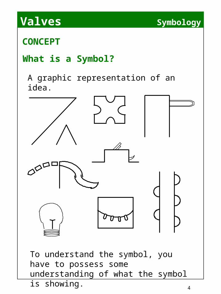
What is a Symbol?
A graphic representation of an idea.
To understand the symbol, you have to possess some understanding of what the symbol is showing.
CONCEPT
Valves
5
Symbology
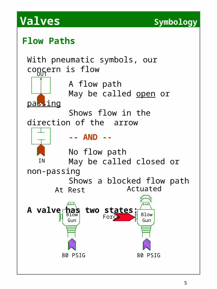
Flow Paths
With pneumatic symbols, our concern is flow
A flow pathMay be called open or
passingShows flow in the direction of
the arrow
-- AND --
No flow pathMay be called closed or non-
passingShows a blocked flow path
A valve has two states:
OUT
IN
80 PSIG
Force BlowGun
80 PSIG
BlowGun
ActuatedAt Rest
Valves
6
Symbology
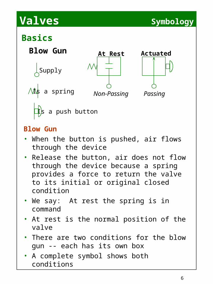
Blow Gun• When the button is pushed, air flows
through the device• Release the button, air does not flow
through the device because a spring provides a force to return the valve to its initial or original closed condition
• We say: At rest the spring is in command
• At rest is the normal position of the valve• There are two conditions for the blow
gun -- each has its own box• A complete symbol shows both
conditions
Basics
Is a spring
Is a push button
Supply
Blow Gun At Rest
Non-Passing Passing
Actuated
Valves
7
Basic Information
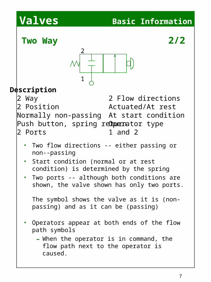
• Two flow directions -- either passing or non--passing
• Start condition (normal or at rest condition) is determined by the spring
• Two ports -- although both conditions are shown, the valve shown has only two ports.
The symbol shows the valve as it is (non-passing) and as it can be (passing)
• Operators appear at both ends of the flow path symbols
- When the operator is in command, the flow path next to the operator is caused.
Two Way 2/2
1
2
Description2 Way2 PositionNormally non-passingPush button, spring return2 Ports
2 Flow directionsActuated/At restAt start conditionOperator type1 and 2

Valves
8
Symbology
• At rest, this valve allows supply to pass through when actuated, flow is interrupted.
• There is no standard for labeling ports that is universally accepted by all manufacturers.
• Referred to as 2/2 for two ported/two position without regard for flow path.
Two Way 2/2
1
2
Description2 Way2 PositionNormally-passingPush button, spring return2 Ports
2 Flow directionsActuated/At restAt start conditionOperator type1 and 2

Valves
9
Symbology
Operators
• Push Button
• Solenoid
• Air Pilot
• Solenoid/Air Pilot
• Detent
• Hand Lever
• Cam Roller
• Spring
• Treadle/Foot Pedal
• Manual
Common Pneumatic Operators

Valves
10
Symbology
1
2
Symbol shows valve actuated
Force
1
2
IF, as shown above, we now release the button --after shifting the valve and extending the cylinder …
WHAT WHAT HAPPENS?HAPPENS?
Are You Certain?Why?
Application
Circuit #1 Single acting air cylinder
•Requires air pressure to extend -- spring will retract the cylinder
•Only one port, rod end open to atmosphere -- vented
• If we push the button, the cylinder extends, compressing the spring
At Rest

Valves
11
Symbology
Application
1
2
1
2
Valv
e #1
Valv
e #2 Note: Arrow has
changed direction indicating correct flow direction
The only way to retract the cylinder is to exhaust (vent) the trapped air
downstream of valve #1
Valve #1 at rest Cylinder is retracted (spring)Actuate Valve #1 Cylinder extendsRelease Valve #1 Cylinder stays extendedActuate Valve #2 Cylinder retractsRelease Valve #2 No action
Now -- @ Start:
If the cylinder was a double acting air cylinder -- we’d have to do this at both ports…

Valves
12
Symbology
Flow Paths --- Three Way Valves
Combine a normally non-passing 2-position 2-way
andA normally passing 2-position 2-way
Valves
13
Symbology
Three Way 3/2
1
2
3
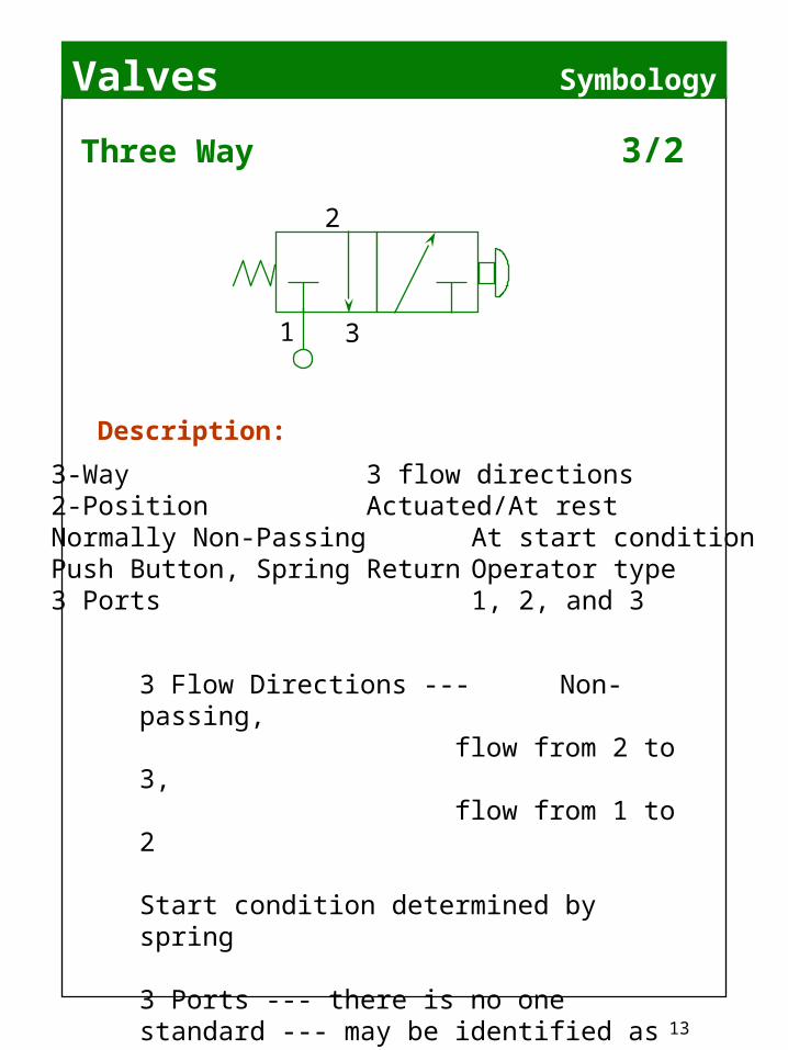
3-Way 3 flow directions2-Position Actuated/At restNormally Non-Passing At start conditionPush Button, Spring Return Operator type3 Ports 1, 2, and 3
Description:
3 Flow Directions --- Non-passing, flow from 2 to 3,flow from 1 to 2
Start condition determined by spring
3 Ports --- there is no one standard --- may be identified as P, C, E or P, C, X or various other systems. You must verify function --- do not assume!
Valves
14
Symbology
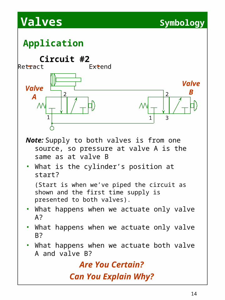
Note: Supply to both valves is from one source, so pressure at valve A is the same as at valve B
• What is the cylinder’s position at start? (Start is when we’ve piped the circuit as shown and the first time supply is presented to both valves).
• What happens when we actuate only valve A?
• What happens when we actuate only valve B?
• What happens when we actuate both valve A and valve B?
Are You Certain?Can You Explain Why?
Application
1
2
1
2
3
ValveA
ValveB
Circuit #2Retract Extend

Valves
15
Symbology
Three Way 3/2
1
2
3
3-Way 3 flow directions2-Position Actuated/At restNormally Passing Start conditionPush Button, Spring Return Operator type3 Ports 1, 2, and 3
Description:
3 Flow Directions ---Non-passing, flow from 1 to 2flow from 2 to 3
Start condition determined by spring
Ports may be labeled in different ways

Valves
16
Symbology
Note: Supply pressure identical at both valves
Observe arrows representing correct flow directions
• What is the cylinder’s position at start?
• What happens when we actuate only valve A?
• What happens when we actuate only valve B?
• What happens when we actuate both valve A and valve B?
Application
1 3 1
2
3
ValveA
ValveB
Circuit #3Retract Extend
2
Valves
17
Symbology
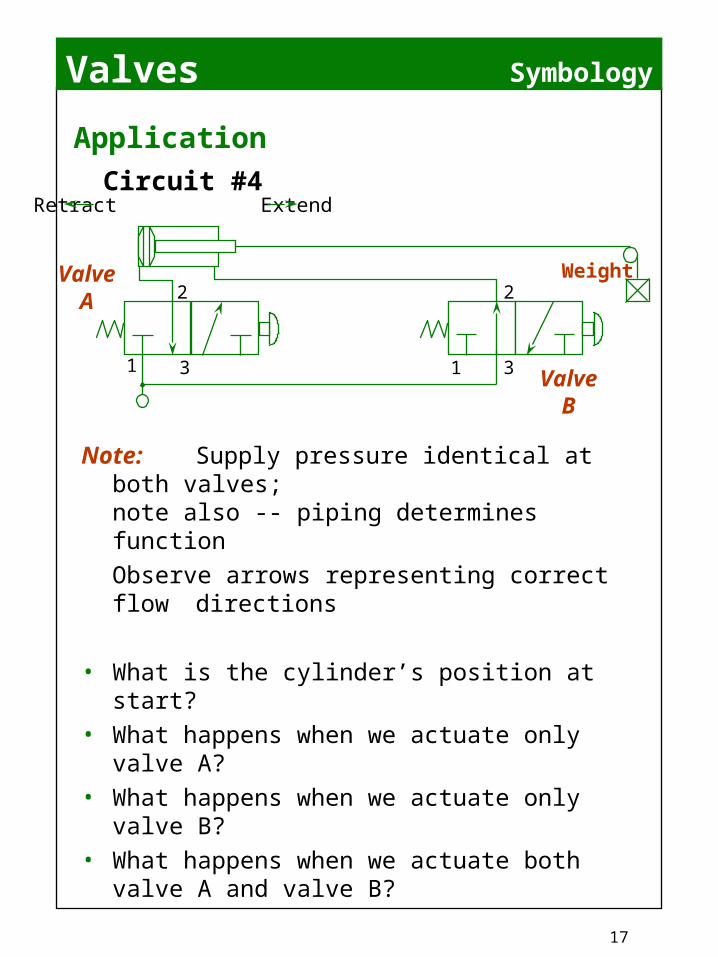
Note: Supply pressure identical at both valves;
note also -- piping determines function
Observe arrows representing correct flow directions
• What is the cylinder’s position at start?• What happens when we actuate only
valve A?• What happens when we actuate only
valve B?• What happens when we actuate both
valve A and valve B?
Application
1 3 1
2
3
ValveA
ValveB
Circuit #4Retract Extend
Weight2

Valves
18
Symbology
3 2
14
3
2
1
3
2
1
Two 3-Ways Combined = One 4-Way, 4-Ported
One Normally Non-Passing 3-Way
+ One Normally Passing 3-Way
= One 4-Ported, 4-Way
Flow Paths --- Four Ported Four Way 4/2
Valves
19
Symbology
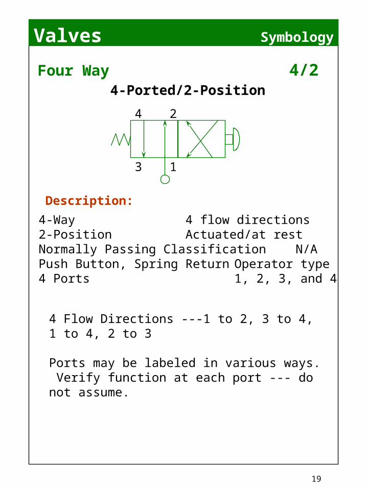
Four Way 4/2
4-Way 4 flow directions2-Position Actuated/at restNormally Passing Classification N/APush Button, Spring Return Operator type4 Ports 1, 2, 3, and 4
Description:
4 Flow Directions ---1 to 2, 3 to 4, 1 to 4, 2 to 3
Ports may be labeled in various ways. Verify function at each port --- do not assume.
4-Ported/2-Position
3
2
1
4
Valves
20
Symbology
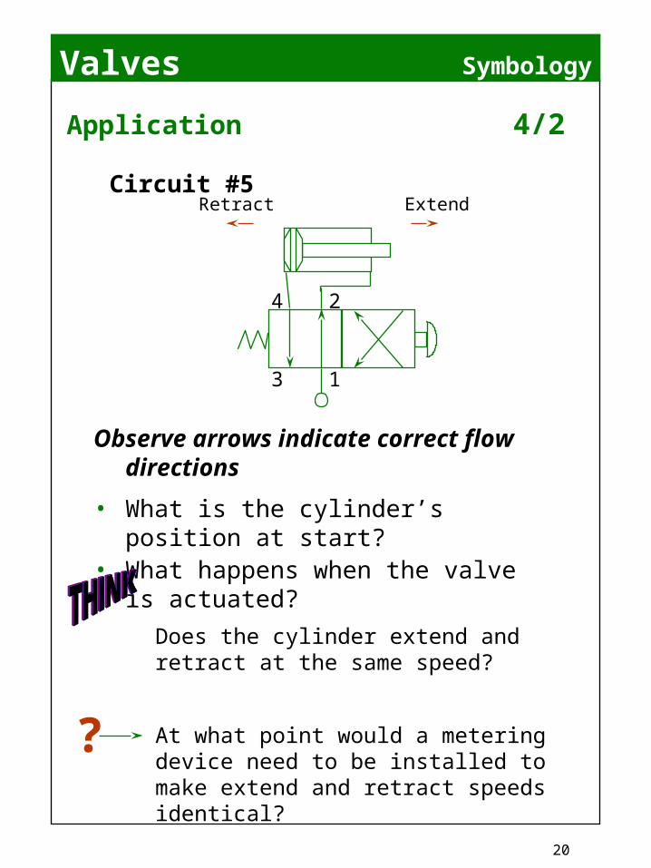
Observe arrows indicate correct flow directions
• What is the cylinder’s position at start?
• What happens when the valve is actuated?
Application 4/2
Does the cylinder extend and retract at the same speed?
At what point would a metering device need to be installed to make extend and retract speeds identical?
?
Retract Extend
3 1
4 2
Circuit #5

Valves
21
No Flow Flow
Check ValveNeedle Valve
Restriction + Adjustment =
CHAPTER 8\
Metering Devices: used to restrict flow--- making a cylinder slower ONLY.
Adjustability is determined by a tapered needle valve. Addition of a checked flow path allows a greater flow in one direction “Free Flow” into cylinder.
Metering Devices
“Free” FlowRestricted
FREE FLOW
C
TO CYLINDER
L
Needle + Check = Flow Control
Flow Control
Flow Controls
Valves
22
Symbology
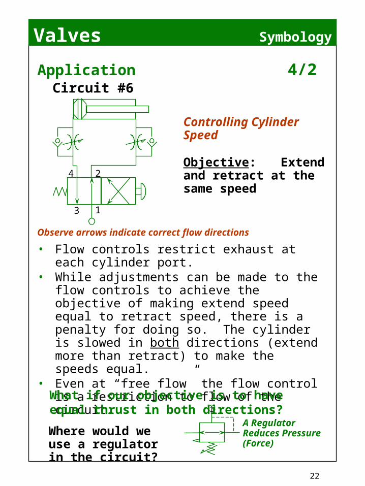
Observe arrows indicate correct flow directions
• Flow controls restrict exhaust at each cylinder port.
• While adjustments can be made to the flow controls to achieve the objective of making extend speed equal to retract speed, there is a penalty for doing so. The cylinder is slowed in both directions (extend more than retract) to make the speeds equal.
• Even at “free flow” the flow control is a restriction to flow of the circuit.
Application 4/2Circuit #6
3 1
4 2
1
What if our objective is to have equal thrust in both directions?
Where would we use a regulator in the circuit?
A Regulator Reduces Pressure (Force)
Controlling Cylinder Speed
Objective: Extend and retract at the same speed

Valves
23
Symbology
Application 4/2
Objective: Extend and retract with
same force
3-way valve used as Selector
Selects line pressureor
reduced pressure
Circuit #7
3 1
4 2
3 1
2
1
Regulators are not designed for exhausting a cylinder --- unless they are equipped with an “internal check” bypass.
Do not use a regulator down-stream of a valve without verifying “check/bypass” function.
Note: Both valves are simultaneously actuated
• Which port is the exhaust port for the circuit?
• Regulator is adjusted until extend and retract forces are identical.
Valv
e A
Valv
e B
Valves
24
Symbology
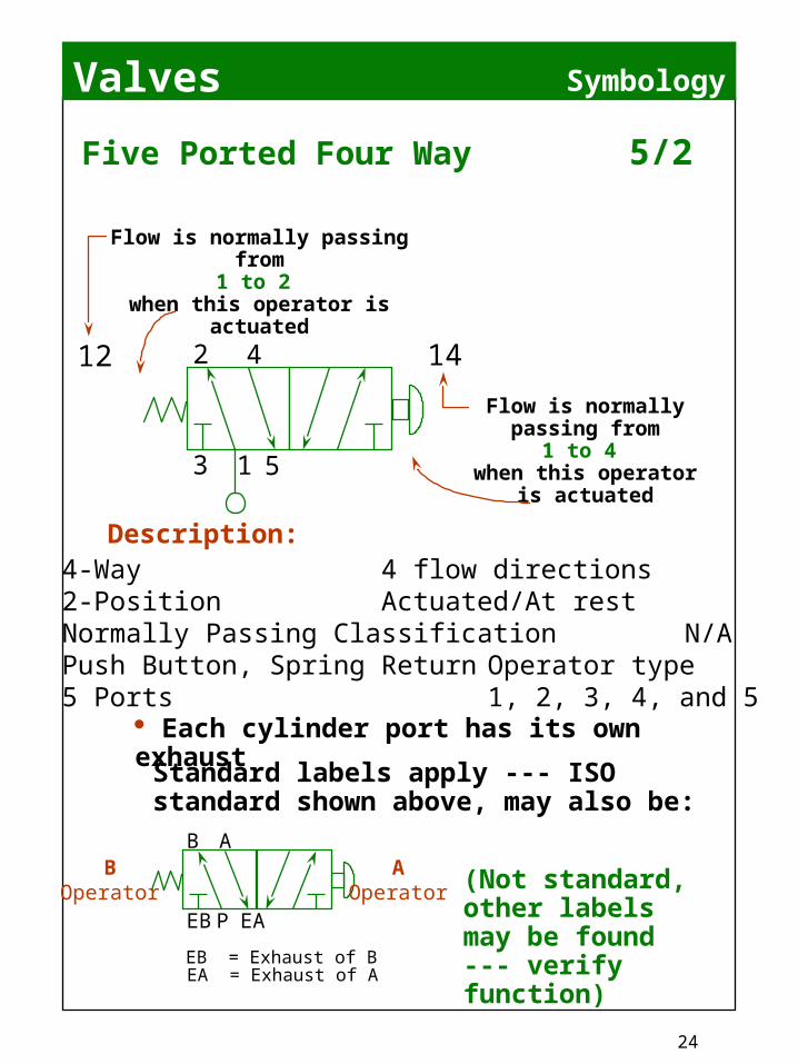
Five Ported Four Way 5/2
Flow is normally passing from
1 to 4 when this operator
is actuated
Flow is normally passing from
1 to 2 when this operator is
actuated
12 14
4-Way 4 flow directions2-Position Actuated/At restNormally Passing Classification N/APush Button, Spring Return Operator type5 Ports 1, 2, 3, 4, and 5
Description:
B A
EB EAP
EB = Exhaust of BEA = Exhaust of A
BOperator
AOperator (Not standard,
other labels may be found --- verify function)
Standard labels apply --- ISO standard shown above, may also be:
Each cylinder port has its own exhaust
42
13 5
Valves
25
Basic Information
B A
EB EAP
B A
2 4
12 14
2 4
1 53
B A
A B
EA EBP
A B
3 51
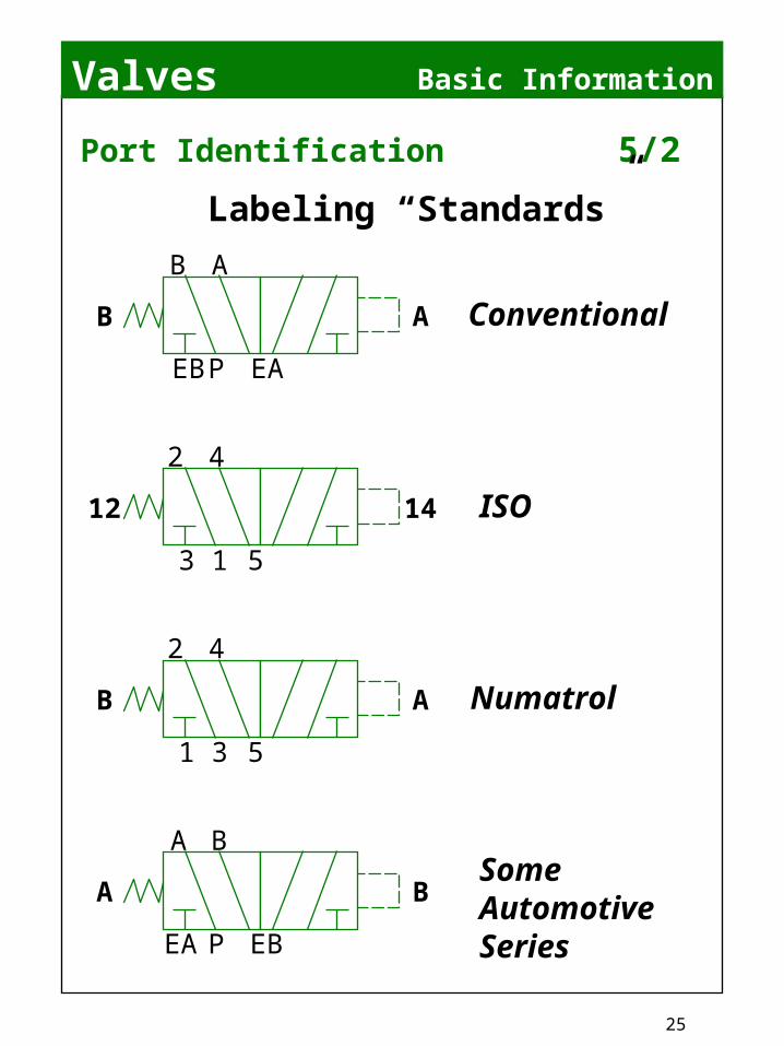
Port Identification 5/2
Labeling “Standards”
Conventional
ISO
Numatrol
Some Automotive Series

Valves
26
Symbology
NOTE:• Dotted line indicates an assembly --- a modular
combination of devices; in this case a valve and a speed control sandwich.
• Metering devices are needle valves and serve to restrict only the exhaust --- supply is full flow.
• Modular design allows control from the valve (often the cylinder is inaccessible or in a protected cell).
• Only by restricting both exhaust flow paths can we extend and retract at the same speed
Application 5/2
Objective: Extend and retract at the same speed
Circuit #8
5 1
4 2
14 12
3

Valves
27
Symbology
NOTE:• Dotted line indicates an assembly --- a
modular combination of devices; in this case a valve and a double regulator sandwich.
• IMPORTANT! Observe that the addition of the sandwich regulator has altered the valve flow paths.
• Modular design allows control from the valve’s location.
• A direct acting multi purpose valve can have supply and even different pressures at ports other than 1 or P --- achieving different functions.
Application 5/2
Objective: Extend and retract with same force
Circuit #9
3 1
2 4
12 14
5R R
Is a shorthand symbol for a regulator
A means of showing lines that do not connect
Lines that do connect
1R

Valves
28
R R
Symbology
Common Multi-Purpose Pipings
2-Way NNP
3-Way NNP
Pressure Diverter
Single Pressure
Double Capacity, NNP 2-Way
2-Way NP
3-Way NP
2 Pressure Selector
Dual Pressure
Double Capacity, NNP 3-Way
R R
Valves
29
Symbology
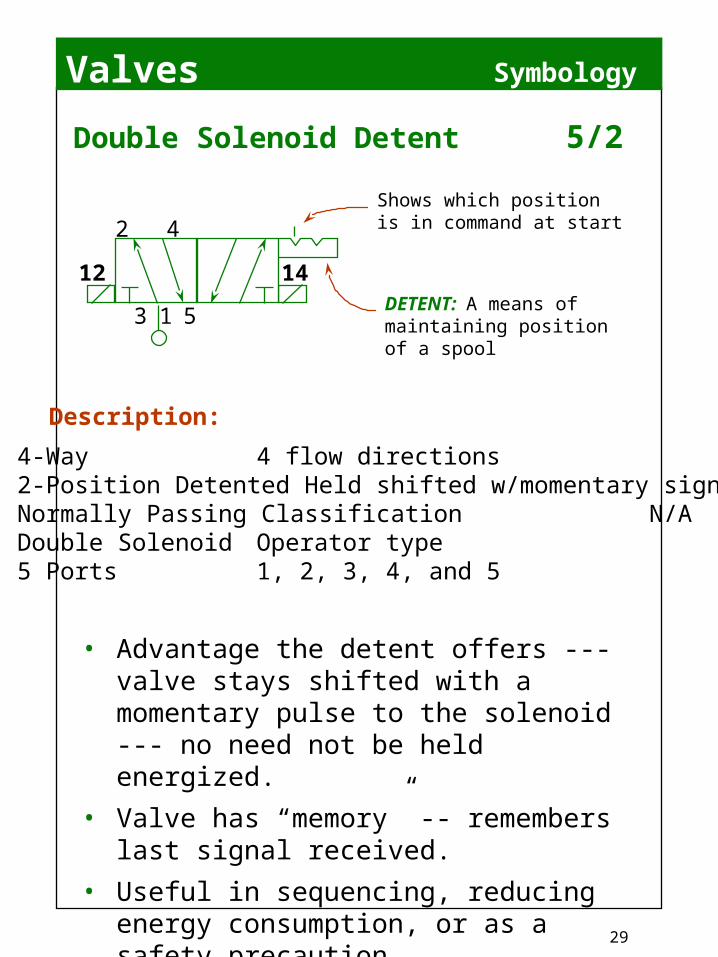
Double Solenoid Detent 5/2
4-Way 4 flow directions2-Position DetentedHeld shifted w/momentary signalNormally Passing Classification N/ADouble Solenoid Operator type5 Ports 1, 2, 3, 4, and 5
Description:
• Advantage the detent offers --- valve stays shifted with a momentary pulse to the solenoid --- no need not be held energized.
• Valve has “memory” -- remembers last signal received.
• Useful in sequencing, reducing energy consumption, or as a safety precaution.
DETENT: A means of maintaining position of a spool
Shows which position is in command at start
3 1
2 4
12 14
5
Valves
30
Symbology
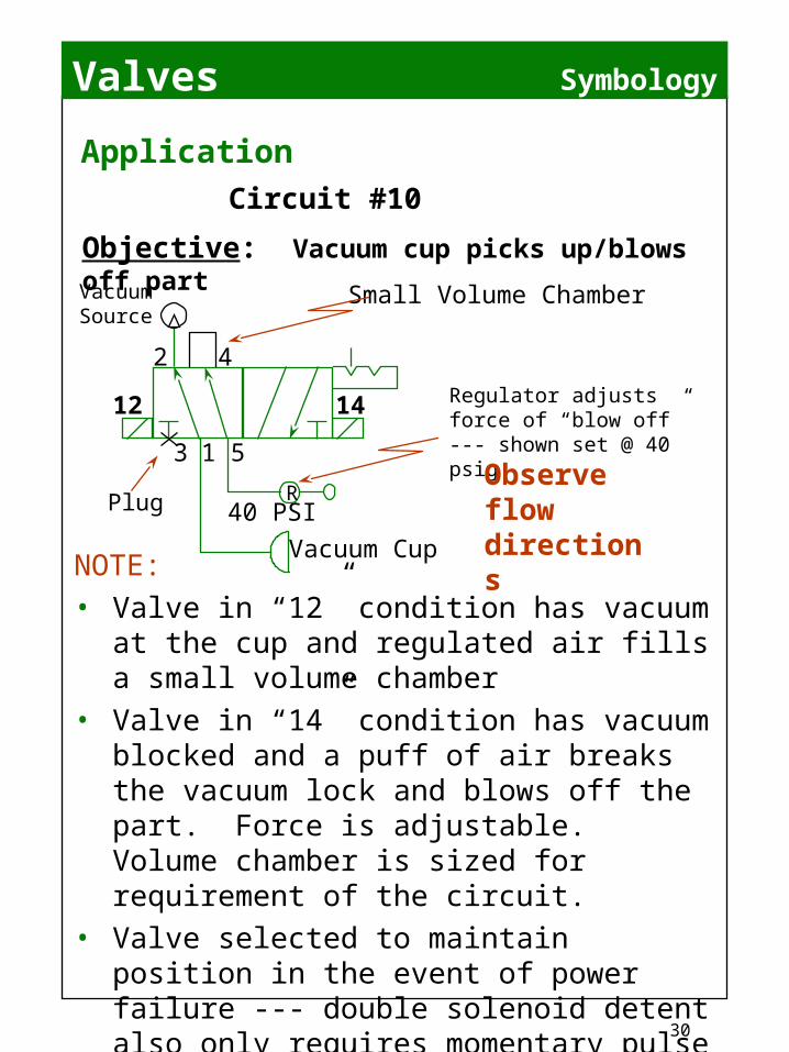
NOTE:• Valve in “12” condition has vacuum at
the cup and regulated air fills a small volume chamber
• Valve in “14” condition has vacuum blocked and a puff of air breaks the vacuum lock and blows off the part. Force is adjustable. Volume chamber is sized for requirement of the circuit.
• Valve selected to maintain position in the event of power failure --- double solenoid detent also only requires momentary pulse of electricity
• Single valve solution: saves energy, adds fail safe function and allows adjustability of the blow off.
Application
Objective: Vacuum cup picks up/blows off part
Circuit #10
Regulator adjusts force of “blow off” --- shown set @ 40 psig
Observe flow directions
40 PSI
Vacuum Cup
Small Volume ChamberVacuum
Source
3 1
2 4
12 14
5
Plug R
Valves
31
Symbology
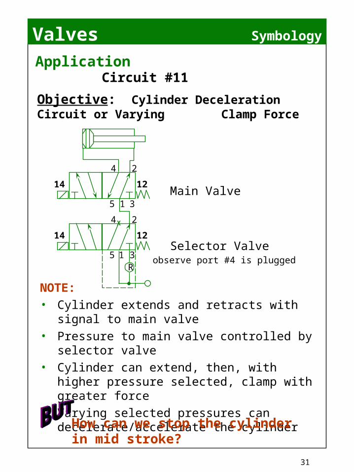
NOTE:• Cylinder extends and retracts with signal to
main valve• Pressure to main valve controlled by
selector valve• Cylinder can extend, then, with higher
pressure selected, clamp with greater force• Varying selected pressures can
decelerate/accelerate the cylinder
Application
Objective: Cylinder Deceleration Circuit or Varying Clamp Force
Circuit #11
Main Valve
Selector Valve
How can we stop the cylinder in mid stroke?
5 1
4 2
14 12
3R
5 1
4 2
14 12
3
X
observe port #4 is plugged
Valves
32
Symbology
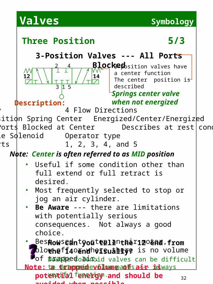
Three Position 5/3
4-Way 4 Flow Directions3-Position Spring Center Energized/Center/EnergizedAll Ports Blocked at Center Describes at rest conditionDouble Solenoid Operator type5 Ports 1, 2, 3, 4, and 5 Note: Center is often referred to as MID position
Description:
• Useful if some condition other than full extend or full retract is desired.
• Most frequently selected to stop or jog an air cylinder.
• Be Aware --- there are limitations with potentially serious consequences. Not always a good choice.
• Best used to stop an air motor, blow-off or where there is no volume of trapped air.
Note: a trapped volume of air is potential energy and should be avoided when possible.
Springs center valve when not energized
3-position valves have a center functionThe center position is described
3-Position Valves --- All Ports Blocked
How can you tell the 12 end from the 14 end visually?Double solenoid valves can be difficult to determine flow paths --- always verify function.
2 4
12 14
3 1 5
Valves
33
Symbology
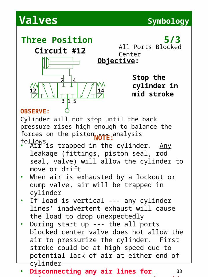
Three Position 5/3All Ports Blocked Center
Objective:
Stop the cylinder in mid stroke
NOTE:• Air is trapped in the cylinder. Any leakage
(fittings, piston seal, rod seal, valve) will allow the cylinder to move or drift
• When air is exhausted by a lockout or dump valve, air will be trapped in cylinder
• If load is vertical --- any cylinder lines’ inadvertent exhaust will cause the load to drop unexpectedly
• During start up --- the all ports blocked center valve does not allow the air to pressurize the cylinder. First stroke could be at high speed due to potential lack of air at either end of cylinder
• Disconnecting any air lines for maintenance may cause unexpected rapid movement of the cylinder --- even if OHSA lock out has been correctly actuated
These actions may occur when least expected
OBSERVE:Cylinder will not stop until the back pressure rises high enough to balance the forces on the piston --- analysis follows.
2 4
12 14
3 1 5
Circuit #12
Valves
34
Symbology
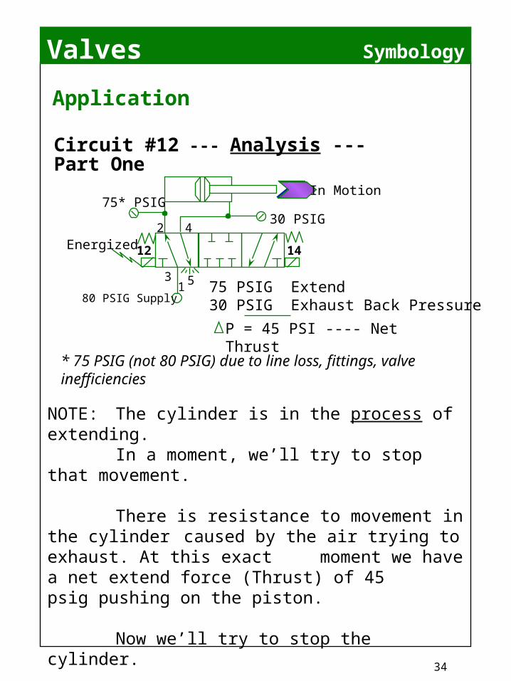
Application
Circuit #12 --- Analysis --- Part One
2 4
12 14
315
80 PSIG Supply
30 PSIG75* PSIG
Energized
In Motion
P = 45 PSI ---- Net Thrust
75 PSIG Extend30 PSIG Exhaust Back Pressure
* 75 PSIG (not 80 PSIG) due to line loss, fittings, valve inefficiencies
NOTE: The cylinder is in the process of extending.
In a moment, we’ll try to stop that movement.
There is resistance to movement in the cylinder caused by the air trying to exhaust. At this exact moment we have a net extend force (Thrust) of 45 psig pushing on the piston.
Now we’ll try to stop the cylinder.

Valves
35
3 15
80 PSIG Supply
30+ PSIG75 PSIG
INERTIA
“Stop” Condition
Inertia -- a body in motion wants to stay in motion
2 4
Therefore: Load cannot “stop” immediately
The Larger the P = The Greater the Over-travel
Symbology
ApplicationCircuit #12 --- Analysis --- Part Two
NOTE: Force is a result of Pressure times Volume (another way of thinking about Area).
On the ROD SIDE, Force will increase as volume is reduced.
On the BLIND SIDE, Force will decrease as volume is provided.
Once the Forces are equal, the cylinder will stop.
NOTE: often forces do not equal within a small cylinder body, but will complete end of stroke due to the volume of air in the tube between the valve and cylinder.

Valves
36
Symbology
Three Position 5/3
4-Way 4 Flow Directions3-Position, Spring Center Energized/Center/Energized Exhaust Blocked, Cylinder Describes at rest condition Ports PressurizedDouble Solenoid Operator type5 Ports 1, 2, 3, 4, and 5
Description:
3-Position Valves --- Cylinder ports pressurized and exhaust ports blocked
NOTE: Description related to center position
Note: Most often used with single pressure piping tostop and hold a balanced cylinder, such as rodless or double-rodded cylinder in a mid-position, with a mechanical rod-lock or carriage-lock.
2 4
12 14
3 1 5

Valves
37
Symbology
Three Position 5/3
4-Way 4 Flow Directions3-Position, Spring Center Energized/Center/EnergizedSupply Blocked, Cylinder Describes at rest condition Ports ExhaustedDouble Solenoid Operator type5 Ports 1, 2, 3, 4, and 5
Description:
3-Position Valves --- Supply blocked, cylinder ports exhausted
NOTE: Description related to center position
2 4
12 14
3 1 5
Note: Most often used with dual pressure piping to stopand hold a double acting cylinder in a mid-position, witha mechanical rod-lock.

Valves
38
Symbology
Application 5/3
Objective: Stop the cylinder in mid stroke
OBSERVE: Cylinder will over-travel and not hold position against external loads
Circuit #13
NOTE:• If cylinder is in mid position, actuating the
valve will cause rapid (potentially dangerous) movement due to large P
• Not suitable for vertical loads• Desirable only for specific applications where
center position function applies
What if the valve was able to be piped in another way?
2 4
12 14
3 1 5
Valves
39
Symbology
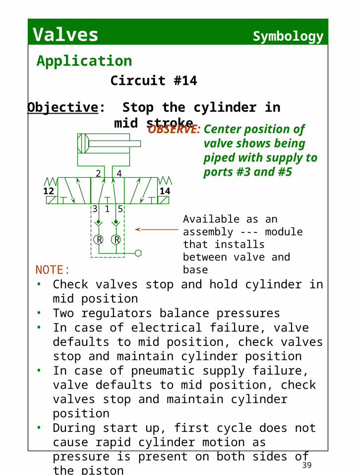
Application
Objective: Stop the cylinder in mid strokeOBSERVE: Center position
of valve shows being piped with supply to ports #3 and #5
Circuit #14
NOTE:• Check valves stop and hold cylinder in mid
position• Two regulators balance pressures• In case of electrical failure, valve defaults to
mid position, check valves stop and maintain cylinder position
• In case of pneumatic supply failure, valve defaults to mid position, check valves stop and maintain cylinder position
• During start up, first cycle does not cause rapid cylinder motion as pressure is present on both sides of the piston
• Be aware that air will be trapped even if an exhaust or lock out valve is opened upstream of this valve
Available as an assembly --- module that installs between valve and base
2 4
12 14
3 1 5
RR
Valves
40
Symbology
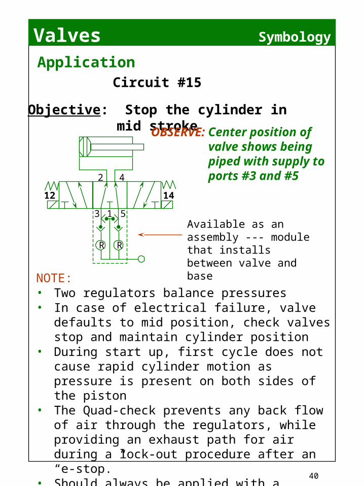
Application
Objective: Stop the cylinder in mid strokeOBSERVE: Center position
of valve shows being piped with supply to ports #3 and #5
Circuit #15
NOTE:• Two regulators balance pressures• In case of electrical failure, valve defaults to
mid position, check valves stop and maintain cylinder position
• During start up, first cycle does not cause rapid cylinder motion as pressure is present on both sides of the piston
• The Quad-check prevents any back flow of air through the regulators, while providing an exhaust path for air during a lock-out procedure after an “e-stop.”
• Should always be applied with a mechanical rod-lock on double acting cylinders.
• BEST “E-Stop” or “jog” circuit.
Available as an assembly --- module that installs between valve and base
2 4
12 14
3 1 5
RR

Valves
41
Construction
Actuation Methods
MANUAL (Direct Acting)
Force to shift valve supplied by mechanism -- linkage directly acts on valveSOLENOID (Direct
Acting)Electromagnet pushes valve. Force is supplied by electrical current -- wattage
Solenoid air pilot requires minimum supply pressure, or, if not available --- must be externally supplied. Typically, internal supply provided only when supply is provided at port #1. Uses air pressure at inlet to shift main valve element.
SOLENOID AIR PILOT
(Direct Acting Solenoid Powers Air Pilot Valve)
2 4
3 1 5
3 1
2 4
5
3 1
2 4
5
Valves
42
Construction
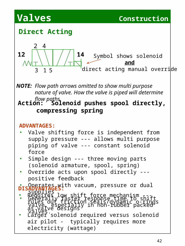
Direct Acting
ADVANTAGES:• Valve shifting force is independent from supply
pressure --- allows multi purpose piping of valve --- constant solenoid force
• Simple design --- three moving parts (solenoid armature, spool, spring)
• Override acts upon spool directly --- positive feedback
• Operates with vacuum, pressure or dual supplies• Generally faster response time to shift valve,
especially in non-rubber packed valves.
NOTE: Flow path arrows omitted to show multi purpose nature of valve. How the valve is piped will determine flow paths.
DISADVANTAGES:• Requires low shift force mechanism --- rules out
friction seals/dynamic o-rings as valve designs• Larger solenoid required versus solenoid air pilot -
typically requires more electricity (wattage)
Action: Solenoid pushes spool directly, compressing spring
Symbol shows solenoid and
direct acting manual override
421412
3 1 5

Valves
43
Solenoids
Solenoid Operators
With current supplied to the coil, an electromagnet is created.
A laminate iron T armature is drawn to the electromagnet. It is this force that shifts the valve mechanism.
An electromagnet takes more energy to create the magnetic force. Once created, less energy is required to maintain the circuit once the armature has been drawn completely to the electromagnet. (Similar to the “flywheel concept – it takes more energy to get the flywheel moving than it does to maintain its motion. Inrush* ----- current required to create the electromagnet Holding* ---- current required to maintain the electromagnet * Peculiar to AC voltage only!
AC coils typically are smaller than DC coils. AC coils typically generate more force per winding --- but they get warm in doing so. (135oF is about maximum)
Current
Armature
Coil ---Windings of Copper Wire
Electromagnet
Valves
44
Construction
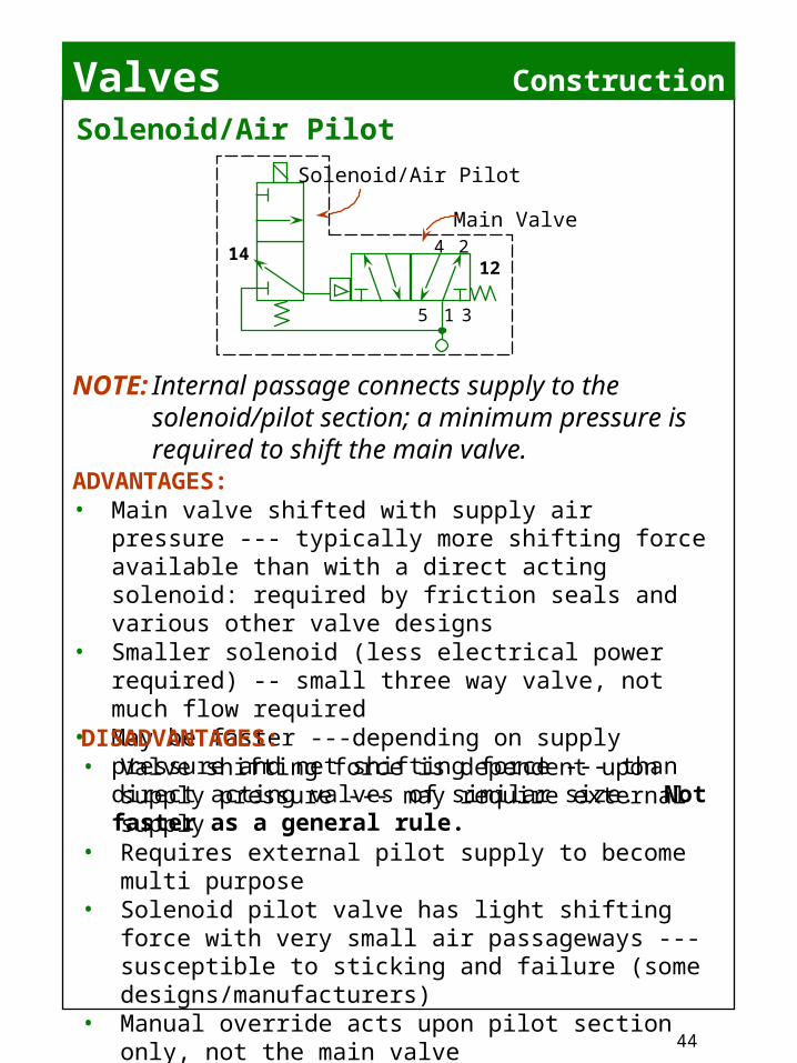
Solenoid/Air Pilot
ADVANTAGES:• Main valve shifted with supply air pressure ---
typically more shifting force available than with a direct acting solenoid: required by friction seals and various other valve designs
• Smaller solenoid (less electrical power required) -- small three way valve, not much flow required
• May be faster ---depending on supply pressure and net shifting force --- than direct acting valves of similar size. Not faster as a general rule.
NOTE: Internal passage connects supply to the solenoid/pilot section; a minimum pressure is required to shift the main valve.
DISADVANTAGES:• Valve shifting force is dependent upon supply
pressure --- may require external supply• Requires external pilot supply to become multi
purpose• Solenoid pilot valve has light shifting force with
very small air passageways --- susceptible to sticking and failure (some designs/manufacturers)
• Manual override acts upon pilot section only, not the main valve
• More parts
5 1
4 2
3
1214
Main Valve
Solenoid/Air Pilot

Valves
45
ConstructionPoppet Type --- Mechanical/Solenoid/Pilot
Position 1
Flow paths when “B” pilot is pressurized or in command
EXHAUST
SUPPLY
CYLINDER
Crossover EXHAUST
SUPPLY
CYLINDER
EXHAUST
SUPPLY
CYLINDER
Flow paths when “A” pilot is pressurized or in command
Position 2
Valves
46
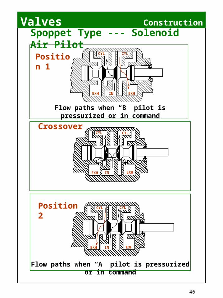
ConstructionSpoppet Type --- Solenoid Air PilotPosition 1
Flow paths when “B” pilot is pressurized or in command
Crossover
Flow paths when “A” pilot is pressurized or in command
Position 2
EXH IN EXH
CYL CYL
EXH IN EXH
CYL CYL
EXH IN EXH
CYL CYL

Valves
47
Construction
Spool and Sleeve Type --- Direct Solenoid/Pilot
Flow paths when “B” pilot is pressurized or in command
B
AB
(2)A
(4)
EB(3)
(12)
(14)
P(1)
EA(5)
AB
A(4)
EB(3)
(12)
(14)
P(1)
EA(5)
(2)B
Mid-Position, all ports blocked – closed crossover
AB
Flow paths when “A” pilot is pressurized or in command
A(4)
(12)
(14)
(2)B
EB(3)
P(1)
EA(5)
Valves
48
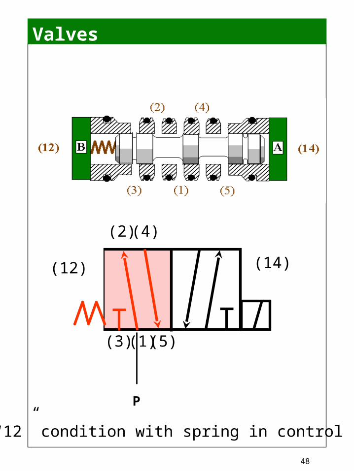
P
(1) (5)(3)
(2) (4)
(12) (14)
“12” condition with spring in control

Valves
49
P
(1) (5)(3)
(2) (4)
“14” condition with solenoid energized
(12) (14)

Valves
50
Basic Information
When selecting a valve ……
What type of valve is best for this application?
Is the circuit design as safe and simple as possible?
What would happen if the lights went out --- will the valve default to a safe condition?

Valves
51
FunctionFunction
13 5
2 4
12 14
13 5
2 4
12 14
2 position, 5 ported, 4 way, Single Solenoid Air Pilot Actuated,Spring Return
2 position, 5 ported, 4 way, Double Solenoid Air Pilot Actuated,Detented
Valves
52
13 5
2 4
12 14
13 5
2 4
12 14
13 5
2 4
12 14
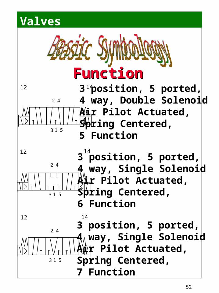
FunctionFunction3 position, 5 ported, 4 way, Double Solenoid Air Pilot Actuated,Spring Centered, 5 Function
3 position, 5 ported, 4 way, Single Solenoid Air Pilot Actuated,Spring Centered, 6 Function
3 position, 5 ported, 4 way, Single Solenoid Air Pilot Actuated,Spring Centered, 7 Function
Valves
53
Summary
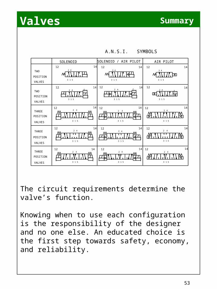
The circuit requirements determine the valve’s function.
Knowing when to use each configuration is the responsibility of the designer and no one else. An educated choice is the first step towards safety, economy, and reliability.
SOLENOID
13 5
2 4
12 14
13 5
2 412 14
13 5
2 412 14
13 5
2 4
12 14
13 5
2 412 14
13 5
2 4
13 5
2 4
13 5
2 4
13 5
2 4
13 5
2 4
12 14
12 14
12 1412 14
12 14
13 5
2 4
12 14
13 5
2 412 14
13 5
2 412 14
13 5
2 412 14
13 5
2 412 14
A.N.S.I. SYMBOLS
TWO
POSITION
VALVES
TWO
POSITION
VALVES
THREE
POSITION
VALVES
THREE
POSITION
VALVES
THREE
POSITION
VALVES
SOLENOID / AIR PILOT AIR PILOT

Valves
54
REVIEW
SymbolsValves
Flow Paths2 Way3 Way4 Way 4 Ported4 Way 5 PortedDetent3 PositionSolenoidMechanicalAir Pilot
CylindersSingle ActingDouble Acting
CalculationsAreaForceCircles
Needle ValvesFlow ControlsInertia
Conclusion

Valves
55
More Symbols

Valves
56
More Symbols

Valves
57
NOTES
Top Related