


Languages
Pages
Legal


LIST OF FIGURES
1 6Bench mark disk and bedrock setting
a. Bench mark disk with typical casting
and stamping
-" Bench mark disk set in bedrockb.
2 10Class B rod marka. Standard installation
b. Marsh installation
312
Bench mark on prefabricated pipe and bench
mark set in concrete monument
a. Bench mark on prefabricated pipe
~. Bench mark set in concrete monument
4 Stability precautions for leveling in wetlands
and marshes 25
5 26Effects of curvature and refraction
6 33Kukkamaki collimation check setup.
7 Example of Kukkamaki collimation checkcalculations 34
8 3710-40 collimation check setup
9 38Example of 10-40 collimation check calculations
xi

bySteacy D. Hicks, Philip C. Morris, Harry A. Lippincott,and Michael C. O'Hargan
Sea and Lake Levels BranchPhysical Oceanography DivisionOffice of Oceanography and Marine Assessment
Rockville, MDOctober 1987
U.S. DEPARTMENT OF COMMERCEClarence J. Brown. Acting S8Cr8t8ry
National Oceanic and Atmospheric AdministrationJ. Curtis Mack II, Acting Under Secretary
National Ocean ServicePaul M. Wolff. Assistant AdminIstrator

Based on the original publication of A. Nicholas Bodnar, Jr.
ii

PREFACE
The primary purpose of this User's Guide is to provide a conven-
ient field reference for Sea and Lake Levels Branch, ship, and
contract personnel engaged in installing bench marks at water
level stations of the Great Lakes and along the marine coasts of
the United States. Equally important are the procedures it
conveys for the required initial and periodic relevelings at
these stations. In planning, the User's Guide enumerates the
necessary information for cost estimates and logistic prepara-tion. Finally, it serves as a documentation of the general
quality of the subject installation and leveling methods.
This User's Guide is the consumation of four progressive manu-
scripts prepared and used by the Sea and Lake Levels Branch. The
first, by A. Nicholas Bodnar, Jr., was drafted in 1975 under the
title, User's Guide for the Establishment of Tidal Bench Marks
and Leveling Requirements for Tide Stations. The second, revised
and edited by A. Nicholas Bodnar, was printed in 1977 under thesame title. With additional material by Harry A. Lippincott on
procedures used in the Great Lakes, the title was changed toUser's Guide for the Establishment of Tidal/Water Level Bench
Marks and Leveling Requirements for Tidal/Water Level Stations.This version was further edited by Richard A. Hess and drafted in
1979. The last, prepared in 1981, was also edited by Mr. Hess
using the latter title.
11i

ACKNOWLEDGMENTS
The original authorship of A. Nicholas Bodnar, Jr. is acknowl-
edged.
Major portions of the publications of Ralph M. Berry, John D.
Bossler, Richard P. Floyd, and Christine M. Schomaker have been
included with appreciation. These portions are both di~ct or
adapted, and cited or inferred. Complete references to these
publications are listed at the end of this document.
The authors are particularly grateful to Josephine E. Bergner andPauly H. Plunkett for typing the manuscript with its many
revisions. In addition, the authors are indebted to Mark W.
Allen for designing and constructing all of the diagrams and to
Jill R. Meldon for writing the section on third-order leveling.
The assistance of Emery I. Balazs with the computation examples
and the critical reviews of Gary M. Young. Emery I. Balazs.
Sandford R. Holdahl. and David B. Zilkoski are very much
appreciated.
The authors also thank Henry R. Frey for his continued interest
and support as well as for his scheduling arrangements which
enabled timely completion.
v

TABLE OF CONTENTS
PAGE
PREFACE
ACKNOWLEDGMENTS
LIST OF FIGURES
LIST OF TABLES
111v
xi
xiii
1.2.
1222
33
3
3
34
4
5
5
7
88
88
9
11
13
14
14
INTRODUCTION '
BENCH HARKS
2.1 Definitions
2.2 Types of Bench Marks
2.3 Number and Type of Bench Mark MOnumentation
at Particular Water Level Stations
2.3.1 Short Period Station
2.3.2 Tertiary Station
- 2.3.3 Secondary Control Station
2.3.4 Pr~ary Control Station
2.4 Primary Bench Hark (PBM)
2.5 Spacing of Bench Marks
2.6 Bench Hark Disk2 . 7 Number ing Bench Marks
2.8 Location of Bench Marks
2.9 Monumentation
2.9.1 Bench Mark Disks Set -in Bedrock
2.9.2 Class A Rod Type Bench Marks
2.9.3 Class B Rod Type Bench Marks
2.9.4 Bench Mark Disks in Large
Man-Made Structures
2.9.5 Bench Hark Disks on Pipes
2.9.6 Bench Mark Diaks in Concrete Monuments
2.9.7 Bench Mark Disk. in Boulders
2.9.8 Maximum Depth of Frost Penetration
vii

PAGE
14
14
15
16
17
17
18
18
3.
19202020222424242828
29
29
31
3235
39
39
40
40
40
2.10 Staff
2.11 Electric Tape Gage (ETG)
2.12 Bench Mark Descriptions, Recovery Notes,
and To Reach Statement
2.13 Bench Mark Sketch
LEVELING
3.1 Standards and Specifications
3.2 Vertical MOvement Precautions
3.3 Frequency of Leveling
3.4 Connection with National Geodetic VerticalDatum (NGVD) . -
3.5 Instruments
3.5.1 Level
3.5.2 Level Rod
3.5.3 Turning Points
3.6 Some Sources of Leveling Error- 3.6.1 Curvature
3.6.2 Refraction
3.6.3 Leveling Collimation Error
3.6.3.1 Collimation check
3.6.3.2 Standard of accuracy for
collimation error
3.6.3.3 Collimation error
3.6.3.4 General instruction for t~
collimation check
3.6.3.5 Kukkamaki method
3.6.3.6 10-40 method
3.6.3.7 Compensation check
3.7 General Observing Routine
3.7.1 Parallax
3.7.2 Balanced Sights
3.7.3 Sight Length
viii

PAGE
3.7.4 Atmospheric Conditions
3.7.5 Closure Tolerance
3.7.6 Cumulative Closure
3.7.7 Leveling Procedures to the Reading
Mark (RM) of the Electric Tape Gage (ETG)
Field Records and Computations
3.8.1 Tabulation and Computation of
Second-Order Levels
3.8.1.1 Three-wire procedures
3.8.1.2 Abstract of precise leveling3.8.2 Tabulation and Computation of
Third-Order Levels3.8.3 Closure Tolerance (2nd- and 3rd-order)
3.8.3.1 Closure procedure
3.8.3.2 Field check of third-order
leveling3.8.3.3 Rejection procedure
Special Cases: Water Crossings, Precise
Reciprocal Leveling, and Unbalanced Sights3.9.1 Water Crossings
3.9.2 Precise Reciprocal Leveling
3.9.3 Unbalanced Sights
414242
4949
50
50
54
576464
6S
66
68
69
69
72
REFERENCES 73
~: Mention of a commercial company or product does not
constitute an endorsement by the National Oceanic and Atmospheric
Administration, National Ocean Service. Use for publicity or
advertising purposes of information from this report concerning
proprietary products or the tests of such products is notauthorized.
ix

LIST OF FIGURES
1 6Bench mark disk and bedrock setting
a. Bench mark disk with typical casting
and stamping
-" Bench mark disk set in bedrockb.
2 10Class B rod marka. Standard installation
b. Marsh installation
312
Bench mark on prefabricated pipe and bench
mark set in concrete monument
a. Bench mark on prefabricated pipe
~. Bench mark set in concrete monument
4 Stability precautions for leveling in wetlands
and marshes 25
5 26Effects of curvature and refraction
6 33Kukkamaki collimation check setup.
7 Example of Kukkamaki collimation checkcalculations 34
8 3710-40 collimation check setup
9 38Example of 10-40 collimation check calculations
xi

FIGURE PAGE
10 Procedures for recording three-wire leveling
including computation of section elevation
difference and length (forward run) 51
11 Procedures for recording three-wire leveling,
including computation of section elevation
difference and length (backward run) 52
12 Example of Abstract of Precise Levels 55
13 Example of Abstract of Precise Levels (continued) 56
14 Third-order level run with foot rod and spur line 59
15 Third-order level run with foot rod and spur line
(continued)
16 Abstract of third-order level run with foot rod
17 Third-order level run with metric rod and a rerun
section due to a bust 62
1863
Abstract of a third-order level run converted from
meters to feet
Precise reciprocal leveling 7119
xii

LIST OF TABLES
1 Curvature and refraction corrections
for single sights 29
Maximum closure tolerance2 44-48
3 Tolerance T factors for closing multiple runs 67
xiii

USER'S GUIDE FOR THE INSTALLATION OF BENCH HARKS
AND LEVELING REQUIREMENTS FOR WATER LEVEL STATIONS
1. INTRODUCTION
A water level* gage, measuring water surface elevation against
t~e, requires a power source, reference point, and water level
bench marks. In addition, a water level station may also include
a stilling or protective well, water level staff or el~ctric tape
gage (ETG), digitizing mechanism (if an analog gage), data storagefacility, encoder, modem for transmission via direct distancedial telephone lines, transmitter for line of sight radio, GOES
satellite transmitter, and shelter (for instrument protection).
Ancillary equipment for water temperature and density, tsunami,
meteorological, and geodetic measurements may also be located atthe station. This Guide, however, is only concerned with the
water level bench marks and their relationship to the water level
staff or ETG. Hereafter, the adjectives, water 1!Y!!, will be
omitted for convenience in most instances.
A network of bench marks is an integral part of the station.
These bench marks are established in the most stable and
permanent material available (bedrock, if possible) in the
general vicinity of the gage. The bench marks are leveledbetween each other and to the staff or ETG. The staff is
permanently attached to a stable structure adjacent to the gageand is mathematically related to it by simultaneous readings of
the gage and ~taff. Thus, the gage measurements are all related
to the bench marks, of which one is designated the primary bench
* The term "water level t" 8S used in this document, replaces the
terms "tide" and "tidal" for coastal regions and "lake level" for
the Great Lakes.

mark (PBM). It follows that the overall quality of datums is
partially dependent on both the quality of the bench mark instal-
lation and the quality of leveling between these marks and the
staff (or other vertical water reference).
BENCH MARKS- ~2.
2.1 Definitions - Bench mar,k is the all-inclusive term for
the fixed physical object, point, or line used as reference for a
vertical or horizontal datum. The bench marks discussed in this
publication are located in the vicinity of a water level station
and in this application are used to reference vertical datums
only. They are the bench marks to which the staff and datums are
referred. Monumentation is the specifi~ type of integral unit
which, when set, contains the referenced elevation by a surface,
line, or point. A monument, per se, is the structure in which
the mark itself is affixed. A bench mark is considered permanent
unless designated a temporary bench mark. Recovering a bench
mark means physically finding and identifying a previously
described (historic) bench mark. Recovery usually involves
providing suggested additions, deletions, and changes to the
existing bench mark description (or noting that the mark was
recovered as described) by the field party for subsequent up-
dating.
2.2 Types of Bench Marks - The most common type of monu-
mentation is a survey disk. The standard bench mark of the
National Ocean Service (NOS) is an installed brass disk about
3 5/8 in. in diameter with a shank about 3 in. long. The disk
contains the inscription NATIONAL OCEAN SURVEYor NATIONAL OCEAN
SERVICE together with other individual identifying information.
Numerous bench marks of predecessor organizations to MOS, orparts of other organizations absorbed into NOS, still bear the
inscriptions, U.S. COAST' GEODETIC SURVEY, U.S. LAKE SURVEY,
CORPS OF ENGINEERS, and U.S. ENGINEER OFFICE.
2

Monumentation of temporary bench marks might be spikes driven
into the base of telephone poles, projecting bolts, or any stable
recognizable object or point.
2.3
Particular Water Level Stations- -
2.3.1 Short Period Station - A short period station is one
at which continuous observations have been made over a period of
less than 30 days. At least three bench marks shall be installed
at this type of station; however, they may be temporary bench
marks of suitable monumentation.
2.3.2 T!rtiary Station - A tertiary station is one at which
continuous observations have been made over a minimum period of
30 days but less than 1 year. At least five bench marks shall be
installed at this type of station. Preference should be given to
disks set in bedrock, in large man-made structures, and on deep
driven rods.
2.3.3 Secondary Control Station - A secondary control
station is one at which continuous observations have been made
over a minimum period of 1 year but less than 19 years. At least
five permanent bench marks shall be installed at this type of
station. Three of the five shall be disks set in bedrock and/or
on deep driven rods. The remaining two shall be installed on the
most suitable structures for the locality. Preference should be
given to disks set in bedrock, in large man-made structures, and
on deep driven rods. Bench mark requirements for the seasonal
datum monitoring proqram in the Great Lakes network are to meet
these specifications.
2.3.4 primary Control Stati2n - A primary control station
is one at which continuous observations have been made over a
minimum period of 19 years. Five bench marks shall be installed
3

during the first year of operation at a station which is intended
to become a primary control station. Additional bench marks
shall be installed in following years until a total of ten have
been installed by the sixth year. At least three of the ten
shall be disks set in bedrock and/or on deep driven rods. The
remaining seven shall be installed on the most suitable stru~tures
for the locality. Preference should be given to disks set in
bedrock, in large man-made structures, and on deep driven rods.
Bench mark requirements for the permanent stations in the Great
Lakes network are to meet these specifications. When installed
by the National Geodetic Survey Division, the class A rod mark
(connected to the National Geodetic Vertical Network by first-
order leveling) should be considered part of the bench mark
network. Existing bench marks of other agencies may be used,
provided the marks meet the specifications for the type of
station.
2.4 Primary Bench Mark (PBM) - One bench mark at each
station is designated the PBM by the Sea and Lake Measurement
Section (N/OMA121), Sea and Lake Levels Branch, PhysicalOceanog-
raphy Division, Office of Oceanography and Marine Assessment.The PBM is selected for stability (or expected stability).
Convenience of location and use are secondary considerations.
Leveling between the PBM and staff zero or ETG reading mark
enables effective monitoring of the vertical stability of the
staff or ETG relative to the PBM. The very localized relative
vertical stability of the PBM is monitored, in turn, by repeated
leveling to the other bench marks at the station. The PBM must
be included in the run each time the station is leveled. See
Section 3.3.
2.5 Spacing of Bench Marks - Bench marks should be distri-
buted in the area around a station such that any expected event
which might disturb a mark will not damage or destroy more than
one mark. This means, for example, that no more than one mark
should be set in a building foundation, on one owner's property,
4

or on the same side of a street where road expansion could occur
Marks should be spaced at least 60 m (200 ft.) from each other,
but no further than 1 km (0.6 mi.) apart. Overall, all bench
marks should be within a radius of about 1.6 km (1 mi.) from the
gage in order to keep leveling time to a min~um.
2.6 Bench Mark Disk - Identification is greatly enhanced by
using standard NOS bench mark disks for bench marks. Those
currently being set are inscribed with NATIONAL OCEAN SURVEYor
NATIONAL OCEAN SURVEY BENCH MARK. In the future, the disks will
be inscribed, NATIONAL OCEAN SERVICE. In the center of the disk
is a circle with a line through its center (Figure la). Some
disks have a tick mark bisecting the line.
2.7 Numbering Bench Marks - To help avoid confusion and
ensure positive identification, new bench marks will be stamped
and designated with the last four digits of the station number,
a letter, and the current year. For example, five new bench
marks set at station 905-2058 would be stamped 2058A, 2058B,2058C, 2058D, and 2058E, along with the current year (Figure la).
Note that the first three numbers (state/lake identifiers) are
not stamped on the mark. Also, the letters I and 0 are not used
since they could be confused with the numbers 1 and O. Duplica-
tion of letters must be avoided; a number previously assigned to
a bench mark shall not be used for a new mark. A mark replacing
a destroyed mark shall be stamped with a new letter. For example,
if bench marks 2058A, 2058C, 2058D, and 2U58E are recovered andbench mark 2058B has been destroyed, the bench mark disk set to
replace bench mark 2058B will be stamped 2058F with the current
year. Station numbers are assigned by N/OHA12l. All stations
are assigned a number regardless of length of operation. Exist-
ing bench marks that have not been s tamped according to the
current numbering system retain the designation stamped on the
mark. Temporary bench marks are not stamped, but are referred to
as TBM I, TBM 2, TBM 3, etc.
5

.00"'-InI
M
~0'\"'"
,"EU
L
I- ~00"".v"'I
M
"£U
'6
r
.Q)"""-
-1
~(\J"'"
"'"EU
.£.
+'0-
_3
~O)V)c:
~O)~d5t.U a.d E:
~~dd+-
.c~""U~C~GA-c
~ d
..Q
..x:~-..x:Qu..x: °
t.t.d~
~QI~
.£.cU-c
QJofoJ~W
(.I')
~
oX{.d
X
~UcOJ
~
~-~~
~c:d
oXU0l.
"'0a"
~

2.8 Location of Bench Marks - The choice of location is
critical to prolonging the life and usefulness of the bench mark.
The choice should be made carefully, considering the likelihood
of the mark being destroyed. Permission must always be obtained
from the landowner. It is desirable to set the face of the benchmark disk horizontally for convenience in holding the level rod,
and there should be sufficient vertical clearance above the mark
for rods used in first-order leveling which are about 3 m (10 ft.)
long. Depending on the area, greater p~rmanency may be assured
by placing the bench mark disk vertically in the wall of a
structure or bedrock. In this position, the line through the
center of the disk becomes the reference elevation. Care must be
taken to ensure that this line is set horizontally. The disk
should be about 1 m (3 ft.) above the ground for convenience in
holding a tape or special short rod/scale used in leveling to the
reference point.
Public squares and parks are preferable places for bench marks.
Public structures are generally preferable to private, since they
have a longer life expectancy.
When setting marks along a highway, locate them near the edge of
the right of way, away from intersections, and on alternating
sides of the road in order to minimize the chances of all marks
being destroyed by road repair or construction. Since highwaycurves are flattened more often than sharpened, the outside of
the curve is usually safer. Avoid setting a majority of the
marks along anyone road or in anyone structure.
High ground is preferable to low lying areas. The water table is
usually closer to the surface in low areas, thereby increasing
the chance of frost heave. Also, fluctuations in water content
are greater in low areas, thereby increasing the chan~e of
swelling and shrinkage if expansive soils are present. Slopesare potentially unstable and should be avoided.
7

2.9 Monumentation - The installation of the more common
types of monuments are discussed in Sections 2.9.1 through 2.9.7,
in order of preference. It should be remembered that good
craftmanship will increase life expectancy, increase stability,
enhance appearance, and be a credit to NOS.
2.9.1 Bench Mark Disks Set in Bedrock - Bench mark disks in
outcrops of bedrock (not boulders) are the most stable and easiest
to set (Figure 1b). A '/8-in. diameter hole, 3 1/4 in. deep, is
drilled into the rock to accommodate the shank of the disk. This
is done with a powered rock drill or by hand using a star drill
and hammer. Next, a counter-sunk solid level base is chiseled
for the disk. The rock is then wetted to p'(:8vent absorption of
water from the cement paste. Cement paste is placed in the hole
and on the underside of the disk to prevent air from becoming
trapped in the concave portion. The cement paste should have a
stiff consistency, but still be workable. The prestamped disk is
then tapped into the drill hole and leveled using a small line
level. Finally, the excess paste is removed and the mark cleaned
by rubbing dry cement powder over the finished mark. In hot
weather, a wet cloth placed on top of the' disk will help prevent
the cement paste from drying too fast and cracking.
2.9.2 Class A Rod Type Bench Marks - These marks are not
generally set by the Sea and Lake Levels Branch because of the
heavy support equipment needed for installation. The National
Geodetic Survey Division plans to set one of this type at each
primary control station. They are probably the most stable (next
to bedrock) and shall be included in the station levelings where
available. The class A rod mark consists of an outer pipe insert-
ed in an augered hole and an inner rod driven to refusal in a
stable soil layer with a truck mounted rig (Floyd, 1978, pp.14-2S).
2. 9. 3 Class B Rod Type Bench Marks - Thi s mark, coDDOOnly
called a deep rod mark, consists of a 9/16-in. diameter stainless
8

steel rod driven vertically into the ground. A specially adapted.
prestamped disk is crimped to the top of the rod. The mark is
protected by a 5-in. PVC pipe and surrounded by a concrete kick-
block (Figure 2a). This type of mark tends to be more stable
than all other types of bench marks except for those set in
bedrock and class A rod marks. The rods are in 4- or 5-ft.
sections, joined tightly with internal threaded couplers and pipe
compound, and are driven with a 56-lb. gasoline hammer or a
3O~lb. manual drop hammer having a minimum drop of 2 ft. A short
section of rod (securely threaded on top) is used as a driving
head. A clockwise torque of 1/2 turn every 5 ft. is applied, by
p~pe wrench, during the driving in order to prevent loosening of
the threaded couplers. A pointed end section of rod facilitates
driving. The procedure for setting a class B rod mark is given
in Floyd (1978, pp.25-26).
Soilcrete may be used for the kickblock instead of concrete when
the latter is not available. Soilcrete is made by adding one
part cement with six parts native soil and only enough water (use
only fresh water) to make the mixture slightly damp. The mixture
is then thoroughly compacted.
In remote unpopulated areas where periodic flooding or continual
submergence of low lying terrain WOQld result in the deposition
of sediments around or over the upper portion of the deep rod
mark, the following procedures should be followed. The bench
mark disk is attached to the rod 1.0 ft. (0.3 m) above thenatural grade. A 5-ft. section of schedule 40, 5-in. PVC pipe
with drainage holes drilled in the upper portion is set aroundthe disk and rod and driven into the ground (Figure 2b).
2.9.4 Bench Mark Disks in Large Man-Made Structures - All
structures resting on bedrock or having deep foundations are
excellent for bench marks. In general, buildings over three
stories high, towers, and bridge abutments are suitable. These
9

10
"fs.g.pCdd~
"'d""...
~'c
d-N
i§Lot'dd
%=d
...,allNc
(\J
Q11-~9
La..
..xl.d
~
~0
~
~
.."
.."d
U

structures, as a group, tend to be the next most stable locations
for bench marks.
Most buildings, however, settle, the rate of settlement decreases
with time. Most of the settlement occurs in the first few years;
therefore, marks are never to be set in structures less than 5
years old. Curbs, sidewalks, pavements, porches, and small sea-walls are not to be used. These structures move due to soil,
moisture, and frost action, and generally have a relatively short
life expectancy. In areas with expansive soils, most surface
structures (even large buildings with shallow foundations) are
subject to heaving and settling.
permission will usually be granted for the installation of a
bench mark disk when its use is explained to the owner or appro-
priate authority. Marks must be set neatly so as not to deface
the structure. The technique for setting a disk in large man-made
structures is identical with that described for bedrock in Section
2.9.1.
2.9.5 Bench Mark Disks on Pipes - This type of mark is made
from prefabricated pipe or a section of 9/l6-in. diameter metalrod with a disk on top and a base plate on the bottom (Figure
3a). The pipe is set in a hole backfilled with compacted earth.
It can be installed easily at almost any location, but may be
subject to movement in an unstable area.
A hole is dug with a 6-in. auger or post-hole digger to a depth
that will allow the bench mark to extend about 3 in. (0.08 m)
above grade. The pipe is then set in the hole to ensure full
bearing value of the base plate. The hole is then backfilled
with slightly damp soil and thoroughly compacted in 0.5-ft.
(0.2-m) lifts. If the soil will not compact satisfactorily,
dry soilcrete may be used in the first few lifts. Percolating
rainwater will provide the required moisture for hydration.
11

L0. c ~~I 01
~d Uc
--COld
£OIULM£ddciLC4-OI'-'OLa._l.&..:Ja.~'-'~<[
""oS-foJ-foJQlC
CI?~
.x:3loBd~
~
QI..c-foJUQICloQlu
~c0
U..QM
"£:U(X)
c~'"f
"e:
""
0"".M
"O~ccdOl
E:01:]Q.c-0Q..~
"001OI~
~OIdl.~Ul.c
..QOdU
~COI-l.
Q..~01
C(.?0
..x-Xl.~dd
2::1:
.s:;...c.U~COIOI~
~
M.0
CQI00.
fi'-":0dOl
~..cdUY.c'-QI,Q.
~dCf-QI
d'-C"n.
M
OJ
~~
0)
La...
M.<:) 1.2.

Bench Mark Disks in Concrete Monuments - Concrete2.9.6monuments have been the most frequently used supporting monument
in the past. Since they are subject to movement, however, they
are seldom used today. The monuments, if used, must be at least
1 week old before leveling in order to allow time for initialsettlement.
Concrete is placed in a l-ft. (O.3-m) diameter hole about 3 ft.
(1 m) deep, unless frost action requir~s a deeper ~oundation. A
bell-shape is dug at the base of the hole in order to reduce the
possiblity of heaving or settling. The monument should be formedat the top and free from projections which could assist in lifting
the mark (Figure 3b).
To produce the needed durability and strength of the concrete, a
1:3:2 mix (one part cement, three parts sand, and two parts
gravel) shall be used. The mix should be stiff and rodded in
place. The sand and gravel must be clean and sound. Ready mix
concrete sold in bags generally has a poor aggregate gradation
and low cement content. If ready mix is used, however, extra
sand and cement shall be added as needed.
Concrete mixing water should be potable water. Seawater can be
used, but it will cause a reduction in 'strength of about 20
percent. The reduction in strength can be offset to some degree
by either increasing the cement content and/or reducing the
seawater content. Strength of concrete is increased by decreas-ing the water content as much as workability allows. Full
hydration and maximum strengtb is obtained at water/cement ratiosmuch too dry for workability.
Before placing the prestamped disk in the fresh concrete. cement
paste is placed on the underside of the disk to prevent air from
becoming trapped in the concave part of the disk.
13

2.9.7 Bench Mark Disks in ~oulders - This type of mark is
only acceptable in remote areas when, due to logistic problems,
other types of monuments are not feasible. The boulder must be
large and embedded deep enough to go well below the frostline.
2.9.8 Maximum Depth of Frost Penetration - To guard against
frost heave, both a pipe mark or a disk set in a concrete monu-
ment (or boulder) must go at least 0.3 m (1.0 ft.) below the
frostline. The extreme depth of frost penetration varies but, in
general, it is less than 0.6 m (2.0 ft.) deep along the west
coast of the contiguous United States and south of New Jersey on
the east coast. The extreme depth varies from 1 m (3 ft.) in
northern New Jersey to about 2 m (7 ft.) in northern Maine. The
extreme depth and a table to determine frost penetration is given
in Floyd (1978, p.34).
2.10 Staff - A staff is a graduated board secured to a
pile, etc., near the gage. The rod stop is a convenient point on
the staff used to reference an elevation above staff zero. A
1 1/2-in. by 1 1/2-in. by J/8-in. brass or galvanized angle witha round head bolt (as a definite high point) of the same material
is the reference elevation. The height of the reference above
staff zero is measured with a steel tape, graduated in O.Ol-ft.
intervals, and estimated to the nearest 0.001 ft. The rod stop
on a portable staff is the staff stop on the support board.
2.11 Electric Tape Gage (ETG) - At coastal stations the ETG
is often used in lieu of a staff, where conditions make staff
measurements impractical. At all permanent stations in the Great
Lakes network, the ETG is used as the reference for daily checks
of the principal and backup recording gages.
In leveling to the reading mark of the ETG, a steel tape or
specially designed short level rod is used. The position of the
weighted end of the ETG shall be verified to to.OOl ft. and noted
14

in the leveling record and station report. The weight should be
pinned to the tape so that it cannot move in its sleeve.
2.12 ~ench Mark Descriptions, Recovery Notes, and To ReachStatement - Descriptions of bench marks are of great importance,
for only with these descriptions can the marks be recovered and
used. Descriptions must be accurate, clear, concise, and com-
plete. They are forwarded through appropriate channels with the
leveling record and other station documentation.
The followinq paraqraphs provide detailed instructions on pre-
paring descriptions (NOAA Forms 76-75 and 76-89) for bench marks
located at stations in marine areas. For stations located in the
Great Lakes network, the descriptions (NOAA Form 76-186) are
prepared following the guidelines in Pfeifer and Morrison (1980).
A complete description for all new bench marks and a To Reach
Statement shall be written in the field and neatly printed or
typed on DESC~PTION OF BENCH MARK (NOAA Form 76-75). Previously
described bench marks shall be reported on RECOVERY NOTE, BENCH
MARK (NOAA Form 76-89). If the existing description is adequate
for recovery, the statement, -Recovered as described in ...
(source and date) -, may be entered in the Detailed Report section
on the form. All entries above the Detailed Report section must
be completed. The condition of the mark should always be reported
If a source other than NOS is used, a copy of its complete text
shall be included with the RECOVERY NOTE, BENCH MARK. If the
existing descriptions are inadequate (street names changed,
reference point object moved or destroyed, etc.), resulting in
abnormal time-consuming recovery efforts, a completely reviAed
description shall be written and reported on the RECOVERY NOTE,
BENCH MARK form. particular attention should be paid to docu-
menting the actual stamping on the bench mark during every
recovery.
15

The text of the To Reach Statement provides information needed to
locate the bench marks, station, and staff. Directions should be
given to the general vicinity and then to the exact spot. Theyshould start from a highway intersection or prominent landmark in
the nearest city or town. The staff or ETG shall be referenced
to at least two permanent objects.
The Detailed Description section of the DESCRIPTION OF BENCH MARK
shall first reference the bench mark, by distance and direction,
from the furthest of at least three permanent prominent objects.
Descriptions should be from the furthest to the closest permanent
object until all are tied to the bench mark, preferably at right
angles. Descriptions of the setting and monumentation shall be
included. The number of significant digits shall reflect the
accuracy of the distance measurement. The metric equivalent of
all distances shall be included in parentheses after the English
unit. The directions shall be at least to the nearest 16 compass
points; i.e., north (N), north-northeast (NNE), northeast (NE),
east-northeast (ENE), east (E), etc. Vertical references, if
required, should also be provided at the end of the description.
In areas where three permanent objects are not available or ~o
facilitate recovery, one or two witness posts are set near the
mark for reference. A prefabricated witness post or an 8-ft.,
4 in. by 4 in. treated wooden post projecting 4 ft. above the
ground is used. Prefabricated witness posts are less expensive
and easier to install than the wooden ones, but private land
owners and park directors usually prefer the wooden posts because
they blend into the natural scenery.
2.13 Bench Mark Sketch - A sketch showing the gage, staff
or ETG, and all bench marks is submitted with the leveling
record. This sketch should be on a separate sheet of 8 1/2-in.
by 11-in. paper, at appropriate scale. A new sketch is not
required at previously established stations if the existing
16

sketch is correct and complete. The sketch must have a scale,
north arrow, and title block (NOAA Form 76-199) containing th~
name of the preparer, date, station name, and number.
3. LEVELING-
Quality of leveling is a function of the procedures used, the
sensitivity of the leveling instruments, the precision and
accuracy of the rods, the attention given by surveyors, and the
refinement of the computations.
3.1 Standards and Specifications - The leveling used at
stations shall generally follow the Standards and Specificationsfor Geodetic Control Networks (Bossler, 1984).
Second-order, class I levels shall be used in connections at allprimary and secondary control stations. Although third-order
levels may be used at all other stations, the on-site, self-
checking capability inherent in second-order levels warrants itsuse if at all feasible.
The following tolerances shall be observed in levelings at all
stations:
a.
b.
c.
maximum length of sight, 60 m (197 ft.) for 2nd-
order, class I and 90 m (295 ft.) for 3rd-order;max~ difference in length of forward and
backward sights,
1) 5 m (16 ft.) per setup (2nd-order, class I)
and 10 m (33 ft.) per setup (3rd-order),
2) 10 m (33 ft.) cumulative per section;
maximum closure between forward and backward
runnings, 6 um-VK (0.025 ft. Vii) per section andline (2nd-order, class I) and 12 mm~ (0.050 ft.
;nM) per section and line (3rd-order) - where K
17

d.
e.
and M are the one-way distances in kilometers and
miles, respectively,minimum ground clearance of line of sight, 0.5 m
(1.6 ft.) for 2nd- and 3rd-order, and
determination of temperature gradient for vertical
range of line of sight at each setup, for 2nd-order
only.
3.2 Vertical Movement Precautions - Althouqh the purpose of
relevelinq is to detect movement (or lack thereof) between the
staff or ETG and the marks, certain departures require careful
attention. When the change of height exceeds 6 mm (0.02 ft.) at
primary and secondary control, and 13 mm (0.G4 ft.) at tertiary
stations, a special check should be made for the possibility of a
loose staff or a disturbed bench mark, etc. Stability of the
mark should be determined by leveling to other station marks to
check previously determined height relationships. Any findings
or conclusions should be noted in the Remarks section of the
leveling record~
3.3 Frequency of Levelinq - Leveling between bench marks
and the staff or ETG shall be conducted at all stations unless
otherwise directed:
a.b.
c.
d.
e.f.
at establishment (all bench marks),
6 months after establishment (PBM plus four otherbench marks) - project instructions or contract
documents may modify this requirement,
before and after any modification affecting the
elevation of the staff or ETG (PBM plus two other
bench marks),
upon discontinuation of data collection (all bench
marks),annually (all bench marks),
as often as necessary to ensure minimum data loss
18

at stations exposed to extre~ environmental
conditions (PBM plus two other bench marks), and
g. after installation of new bench marks (PBM plus two
other old bench marks and new bench mark) .
The Project Instructions or contract document will list the PBM
and designate the other bench marks to be connected, as required.
Conne~on with National Geodetic Vertical Da~3.4 -- -(NGVD) - If NGVD is within a one mile leveling distance of the
station, a level connection shall be made, as detailed below,
during one of the required levelings. Stations established
solely for hydrography are exempt from this requirement, except
when otherwise directed. If NGVD is in the immediate vicinity,
the mark(s) can be used for the station if the provisions of
Section 2.3 are satisfied.
For the connection to be meaningful, the observed difference
between two marks of the network must agree with the published
value within the allowable closure tolerance: 6 mm,rK (0.025 ft
~) for second-order, class I levels, and 12 mm~ (0.050 ft..nI) for third-order levels - where K and M are the one-way
distances in kilometers and miles, respectively.
As an example, assume the following using second-order leveling:
Published
Difference
Observed
Difference
BenchMarks Pub.-Obs.Distance
1.00 km
1.00 km2.00 km
+0.100 m
+0.200 m
+0.300 m
-0.010 m
+0.015 m+0.005 m
A - BB - CA - C
+0.110 m
+0.185 m
+0.295 m
The observed difference between A and B did not agree with the
published difference within the allowable closure tolerance (6 mm
-VI.O km- *°.006 m<O.OIO m). therefore. leveling was extended
to C. The difference between B and C did not agree either
19

(to.006 m< 0.015 m). However, the difference between A and Cdoes check [6 mm-V2.0 kIll = to.OOB m>(-0.010 m + 0.015 m =0.005 m)], and the connection is adequate. In this example, Bappears to have moved (become unstable).
3.5 Instruments
COMPENSATOR INSTRUMENTS SPIRIT-LEVEL INSTRUMENTSJena NI 002 Breithaupt NABON
Jena NIO07 Jenoptik Ni 004
Lietz B1 Kern GK2-A
MOM NiA31 Pentax L20
Wild NA2 Wild N3Zeiss NilZeiss Ni2
If other than listed, approval may be granted after instrument
specifications (optic power, repeatability, etc.) are reviewed by
appropriate authority.
Several instruments listed above can be equipped with a device
called an optical micrometer. This device eliminates the need to
estimate the intercept of the middle wire of the reticle as it
appears against the image of the rod scale. Micrometer leveling
is the most precise procedure for geodetic leveling. While pri-
marily used only in first-order leveling, it may also be used in
second-order.
3.5.2 Level Rod - In differential levelinq, verti~al dif-
ferences in elevation between bench marks are measured with a
rod. The accuracy of leveling, therefore, depends on both thequality of the rod and the instrument itself (in addition to
20

procedures and technique). All too often, a very high quality
observing instrument is used with little attention given to the
equivalent quality of the rod.
The rod used in second-order leveling is composed of a single
continuous (not collapsible or folding) lnvar metal scale sup-
ported on a staff of wood or light metal. The scale is perman-
ently attached. to the foot of the staff, and is freely supported
under tension by a spring-loaded clamp at the top.
Thus, the staff is free to ch~nge length in response to changes
in humidity and/or temperature without affecting the length of
the graduated scale. A circular level bubble is used to keep the
rod plumb.
Line-type graduation patterns (double offset scale) are to beused with levels equipped with optical micrometers. Block-type
graduation patterns are to be used with all others. Rod gradua-tion intervals (rod units) may be in 0.01 foot, 0.01 yard, 1
centimeter, or 0.5 centimeter intervals. The actual rod reading
with the 3-wire method is estimated to 0.001 foot, 0.001 yard,
0.1 centimeter, or 0.05 centimeter (tenths of.rod units), respect-
ively. When using a level equipped with an optical micrometer,
the rod graduations and the micrometer'graduations must be in
compatible units of measure, and the actual readings are inhundredths of rod units.
All second-order Invar rods are to be calibrated, with both index
and length errors determined. This requirement may be accom-
plished at the time of purchase by receipt of a calibration
certification from the manufacturer or by calibration and certifi-
cation by an approved laboratory.
For third-order leveling, rods with continuous metal scales on a
wooden or fiberglass staff (calibrated in metric or English units
2.1

in a block graduation pattern) are acceptable.
bubble is used to keep the rod plumb.
A hand-held level
When using two rods. they must be a matched pair (rods with thesame rod units. graduation pattern. index error. etc.). In
addition. two-rod leveling procedures require an even number of
instrument setups per section in order to cancel out any mismatch
error. When using one roG. or if the rod. are calibrated to each
division (detailed calibration). an odd number of setups may beused. The rod type. rod unit. graduation pattern. and serial
number must be referenced in all field notes.
3.5.3 Turnin2 Points - Two important characteristics of any
turning point, which should always be considered when selecting
the type and position, are: (a) its stability while being used
(supporting the running elevation), and (b) the precision of the
rod resting point. The following table lists the most commontypes of turning points, together with the various surfaces
upon which they are used.
22

TURNING POINT SURFACE TYPE REMARKS
Firm ground, dirt roads.Steel pins with
driving cap
Pin is driven vertically
into the ground and
removed when the rodman
moves to the next point.
Remove cap to expose
high point.
Portable turning
plate (turtle)weighing at
least 7 kg
(15 lb.)
Concrete pavement,
hard packed gravel.
Turtle is firmly planted
and removed when rodman
moves to next point.
Use with great caution!
Soft ground, marsh,
sandy shoreline.
Double headed
nail in
wooden stake
Stake is driven to firm
bearing. Nail is driven
into stake to the first
bead for precise point.
Elevation ~an be checkedfor a short time after
run.
Ball bearing or
marble*
Concrete pavement. Ball is firmly placed
in niche of pavement
to prevent movement.
Use with great caution I
PK nail* Asphalt road. Nail is driven into
roadway. Head of nail
is left exposed for point.
Elevation can be checkedfor short time after run.
*Not recommended for geodetic leveling
23

When levels are run across extremely unstable ground (marsh,
swamp, shallow water bodies, etc.), conventional points may be
useless and special equipment may have to be fabricated for the
turning points (Figure 4).
3.6 Some Sources of Levelinv. Error - Two sources of level-
ing errors, curvature and refraction, are described. Corrections
can be applied to ob'served leveling data to minimize the effects
of these known systematic errors. The errors are best minimized,
however, by use of appropriate field obse'rvation procedures.
3.6.1 Curvature - The line of sight of a level instrument
intersects the rod on a level plane. Since the surface of theearth is a curve, a small amount of curvature error, proportionalto the square of the sighting distance, is introduced into eachobservation (Figure 5). Corrections for the curvature error arealways negative (i.e., to be subtracted from the observed rod
readings).
3.6.2 Refraction - Variations in atmospheric density, pri-
marilya function of temperature, cause the line of sight to
refract (bend toward the air of greater density). Scintillation,
the short period boiling of the air, is also caused by differ-
ences in air densities. The effect of refraction is proportional
to the square of the sighting distance and is greatest:
a.b.c.
on sunny windless days,
during unbalanced sights,
when observing near the top of one rod and the
bottom of the other (line of sight going through
layers of significantly different ai~ densities),
when the line of sight approaches the ground at
any intermediate point along the backsight or
foresight line of sight,
d.
24

-"
"EEUUO
If)'''''1J}
XX~ f;EO Q.
OUQO~11"\ 0 +>u , C'"""""'OJ OJ
c--'
..-oOJ..o.C\JvO>d.X.X 0 ~+>C\Jv3~CI?
LQ
25
-c
1.
~
~
~
'*
'*
' '.
~. . ... . . . . . . . . . .
""""""".
~
OJ+» 0-o+> d
z: UCI?
J"O)-Pc----'-
:go..d>
,QI(..1...J
VtVt5"'0-c
-f->d~-d-f->uQlOJ3L
Q,.c -
V1OJ
...cV1L
LdO~
~olJ


e.
f.
when conditions are not the same along both lines
of sight (as in an onshore backsight and offshore
foresight) in non-reciprocal or unbalanced obser-
vations,at night (during calm windless conditions) when
the temperature gradient is positive (i.e., when
the air near the ground is cooler than the air
above), and
when the line of sight passes over a surface with
a high refractive index (e.g., paved roads, sand,9-
etc.
Previously, simple refraction tables were developed that de-
scribed average leveling conditions but, due to the nature of
most coastal leveling, departures from these average conditionsare generally great and thus result in improper corrections.
Refraction error (an~ the resulting corrections) may be positive
as well as negative, depending on the temperature gradient at the
time of observation. The best way to reduce refraction error is
to avoid the causes of refraction in the first place and there-
fore minimize the errors. This may be accomplished by:
a.b.
c.
d.
e.
f.
increasing the height of the instrument,
reducing the sight distance and avoiding unbalanced
sights,taking advantage of cloudy and breezy days to run
levels,keeping the line of sight at least 0.5 m (1.6 ft.)
above the grounq (or any intervening object) at all
points (required),avoiding positive temperature gradient conditions
(usually at night), andconducting observations during the time interval
from 2.5 hours after sunrise to 0.5 hours before
sunset.
27

Additional information on corrections which can be applied to
observed leveling data, including 'formulas, is given in Balazs
and Young (1982).
3.6.3 Leveling Collimation Error (adapted directly fromSchomaker and Berry, 1981, pp. 3-29 through 3-36) - No instrument
is perfectly aligned. The level collimation error is the angle
from which the line of sight departs from the actual level
surface wnen ~he instrument is leveled.
3.6.3.1 Collimation Check - In the field, the collimation.
error of a leveling instrument is measured by obtaining a set of
observations called the collimation check (Peg-test). Collima-
tion error must be reduced by adjusting the instrument to within
a standard accuracy. Because the necessary adjustment can changeeasily under field conditions (thus changing the collimation
error), the collimation check should be made daily with mostinstruments. In addition, the check should be made any time an
instrumen~ sustains a severe shock or seems to function
abnormally.
The collimation check has two purposes: to determine, against a
standard of accuracy, whether the instrument is properly adjusted;
and to compute a factor to correct data obtained from imbalanced
setups and sections.
The error, CR, must be removed from each rod reading. It may beobtained in either one of two ways. The first is to look it upas a function of the sighting distance in Table 1. The second,more precise way, is to compute it as a function of both sightingdistance and a formula for temperature differential (Jordan, et
al., 1956).
Table 1 is the result of computations using the temperature
differential formula and assuming average temperature gradients
28

at a height of 1.5 m (5 ft.) under daytime conditions. Distances
given are for sight lengths permitted by either Kukkamaki or
10-40 methods for collimation check.
Table 1 Curvature and refraction corrections for single sights
DISTANCE (D)
METERS FEETCORRECTION TO ROD READING (CR)
MILLIMETERS FEET -1
2
3
4
5
6
78
9'
336698
131164197230262295
---
-
-0.0001
-.0.0002
-0.0005
-0.0009
-0.0014
-0.0020
-0.0027
-0.0035
-0.0044
3.6.3.2 Standard of accuracy for collimation error - In aproperly adjusted instrument, the collimation error should be nomore than %10.0 arc-seconds (CS%0.05 mm/m). If an instrument
exceeds this tolerance, it must be adjusted and another check
made. Two methods of observation are included in the procedure
for the collimation check.
3.6.3.3 Collimation error - During the collimation check,
the an~lar value of the collimation error is determined. The
tangent of the an~lar value is computed in mm/m.
If the first setup is balanced and the second unbalan~ed (as for
the Kukkamaki method given in 3.6.3.5), then:
~hl - ~h2 + CR.
~s2c -
AS2-
29
000000000
o.o.o.o.o.o.O.1.1.
,0
,0
,1
,2
4
6
8
0
3
275720164

where Ahl - difference in elevation, setup 1
Ah2 - difference in elevation, setup 2
As2 = unbalanced distance, setup 2
CR - sum of curvature and refraction error (-C~ + CRf)'
the error being opposite in sign of correction in
Table 1.
If both setups are unbalanced by the same amount, and they are
leveled in opposite directions, then the corrected elevation
differences are opposite in sign, and:
(Ahl - CRl) + (Ah2 - CR2)~ .681 +~s~ -c -
Since ~sl
<.obI + Ab2) - 2CR2 As -c -
The elevation differences, the curvature and refraction errors,
and the imbalances should be measured in the same units; the
resulting collimation error is a nondimensional value. For
convenience, however, it is often expressed in millimeters permeter. If the collimation error is not within the tolerance for
the survey, the instrument must be adjusted. When adjustment can
be made in the field, the amount of error to be removed is computed
from the following formula. It is referenced to the rod at the
farthest sighting distance, sF' and computed in rod units:
x conversion factorrod unit/DID.
The error is subtracted from the last reading made on the far
rod. The instrument is then adjusted in such a way that the
corrected reading is observed. After performing the adjustment,
30

the entire procedure should be repeated in order to compute and
check the new collimation factor.
Note that the quantity C, commonly used to correct data from
three-wire leveling, is not the collimation error. In the past,
C has been defined as the product of the stadia factor and the
tangent of the collimation error. This was done so that the
tmbalances, expressed in units of stadia interval, could be
converted to units of distance at the same time that a correction
for collimation error was applied to the leveling data. Modern
instruments, rods, and computers make this practice unnecessary.
General instruction for the collimation check - Two3.6.3.4methods, sufficiently precise to satisfy the purpose of thecollimation check, are presented here. However, the accuracy of
the result, with either of these methods, depends on the
assumption that the error observed is entirely a function of
collimation error. Other effects that alter the line of sight,
such as refraction, must be controlled. To achieve this:
a. make the collimation check on uniformly flat
ground, the slope of which should be less than 2%,
b. make the check only when the temperature gradient
is negative (temperature decreases with height). If thermistors
are not available, make the check at least 3 hours after sunrise
on sunny days, or at least 5 hours after sunrise on cloudy days
(this instruction may be disregarded if a damaged instrument
check is conducted immediately following an accident; in thiscase, another check should be made as soon as the negative
gradient conditions can be met),
c. allow the instrument and leveling rods to
acclimatize for at least 5 minutes after removal from their
cases.
d. make sure that the circular bubble levels on the
instrument and rods are properly adjusted, and
31

correct for curvature and refraction.e.
3.6.3.5 Kukkamaki method - The Kukkamaki method for making
a collimation check was developed by T. J. Kukkamaki of the
Finnish Geodetic Institute. The method is especially suitable
for an instrument whose collimation error changes when refocused.
This change may be unacceptable with the more imbalanced setups
of other methods (such as the 10-40 method).
The followinq instructions apply to any instrument-rod combination.
Record data on a standard recordinq form.
a. On the flattest possible ground, layout a setupwith precisely 20 m (66 ft.) between the turning points (using a
tape to measure this and all other distances). Po,sition the
instrument on a line between and precisely 10 m (33 ft.) from
each turning point (Figure 6).b. In the Remarks column of the recording form (NOAA
Form 75-29), enter the instrument type and serial number, rodtype and serial numbers, and the names of the observer, recorder,
and rodman. Check all serial numbers against the equipment
actually used. Label the recording form Kukkamaki Collimation
Check (Figure 7).c. First setup. Level the instrument. Check that the
circular levels on the instrument and the rods are properly
adjusted. Observe and record a set of readings by either the
micrometer or three-wire procedure. Use Rod 1 as the backsight.
Check that the imbalance is no more than 0.4 m (1.3 ft.).
d. Second setup. Position the instrument in line with
the.turning point 20 m (66 ft.) from Rod 1. with Rod 1 as
the backsight, observe and record another set of readings. Check
that the distances are between 19.6 and 20.4 m (64.3 and 66.9
ft.). Remain in position until the collimation error has been
checked.e. Convert the elevation differences, Ahl and ~h2'
from rod units to millimeters. Look up the values for CR at the

[
r 1. 1 1:
'.
\I .I :
........
I f
......
I f...
33
-....................,
~
..................
1 1 1
"+»Cf..
\,D
\,D""
" E:
(/:'/ ~
'~
()v
~~
~4-
MM'-.I'
E-o-
-t"-~c.,.
MM'-.I'
I~~V.-4
~l1/""
(\J
(\.J
-00
CY.
~
'"00
~
b"'OQ.J
OJ+>c U- Q.J-J 'a.-- 'a.-OJ 0> uOJ c-1:J
OJ-dUV)
+>0z:
0
c0-
+'
d£--
-0U
..xu01
..cu
.Y.
dE
d
.Y.
.Y.
:J~

'"..°
..
..
..%.~
:~100-~z
,
WOKZOc-
..
WUC!iC -a:C~ ~u..- :)
UZ ~oOi Q
..10 -"'CC -ZZU 'CWO- .a-C ~""'" U V8CZ
Z 'CCZL -.. ~ - -W °.J'" ~ ~
08W_- ...."
> :. %~ C - ~. W I ~ -
~ . . ~
-.., ~ WW'" ~ ~",-. .- Z .U ... '::!W %~ :)~ ~
~ ~, .cW\ .... .
a 0* ~0~-C~CIONZ:
~~z"M...0.
I",0-.00-
J~
It ~""~
<.~ 2<~
~'~'1
!~
c~<>:.I-
~I-
I-!i,
3"'c°>a.~=
!:
Go
8~
~~1110~-CSill~.
I~
I~
~
I~1~~1
~
~~ ~o ~~-- ~~", 'I
~
34
z~.0.c».0..
~
jJ
J8
j'H-041
If""-
~

in Table 1.two sighting distances, 20 and 40 m (66 and 131 ft.),
Compute the collimation error by:
c -
f. Check C against the standard using:
c s; %0.05 mm/m
If the standard is exceeded, adjust the instrument as follows
g. Compute the error, in rod units, resulting fromcollimation error in the reading made at 40 m (131 ft.) with:
- 40 x C mm/m x conversion factorerrorrod units rod units/um
For half-centimeter rods, the correction to the foresight
readings is 8C.~For centimeter rods, it is 4C. Subtract thisvalue from the foresight reading, obtained on Rod 2 during th~
second setup. The result is the reading that should be obtained
after adjusting the instruments. The instrument must not be
moved until the adjustment is completed. Refer to the instrument
manual for the mechanics of adjusting the instrument.
h. While still in position for the second setup, point
toward Rod 2 and adjust the instrument until the line of sight
intercepts the corrected reading.
i. Repeat the second setup (step d) and compute andcheck the new collimation error. Ahl remains unchanged.
3.6.3.6 10-40 meth2~ - The 10-40 method for making a
collimation check is so called because each setup is unbalanced,
with one rod 10 m (33 ft.) and the other 40 m (131 ft.) from the
instrument.
35

The following instructions apply to any instrument-rod combina-
tion.
a. On the flattest possible ground, layout a setup
with precisely 50 m (164 ft.) between the turning points (using a
tape for measurement). Position the instrument in line between
the turning points, precisely 10 m (33 ft.) from Rod 1 (Fi9Ure
8) .
b. In the Remarks column of the recording form (NOAA
Form 75-29), enter the instrument type and serial number, rodtype and serial numbers, and the name of the observer, recorder,
and rodman. Check all serial numbers against the equipment
actually used. Label the form 10-40 Collimation Check (Figure
c. First setup. Level the instrument. Check that the
circular levels on the instrument and the rods are properly
adjusted. Observe and record a set of readings by either the
micrometer or three-wire procedure. Use Rod 1 as the backsight., d. Second setup. Position the instrument in line
between the turning points, precisely 10 m (33 ft.) from Rod 2.Observe and record another set of readings as in step c, using
Rod 2 as the backsight.
e. Convert the elevation differences, Ah1 andAh2'from rod units to millimeters. Look up the values for CR at the
two sighting distances, 10 and 40 m (33 and 131 ft.), in Table 1.
Compute the collimation error, in millimeters per meter, by the
following formula:
(Ahl + Ah2) - 2 (CR10 - CR40)-- A8. + .6,8A
1 2c -
f. Check the collimation factor against the tolerance:
c S.tO. 05 mInIm
'36

I.
I
,
'.
....
.....
.,.
37
..
....
......
1-
T
J-
T
1- ,
~
(OW)~'-'
E:0
" V~4-
MM'-'
, E:0ro4
~
(\J
N
-00
~
~
.-.
"'00
~
4-of> 0..c.C)Q.I- c
V>-~
Cf-0"0
OJOJ+>c U- OJ
-l ~
- ~OJ 0> uOJ c;-J:J
~0z:.
0of->
QI-dUV)
c0-
+>d£--0
U
..xu01
..r.u
00
0VI
0
"+''I-
MM'"
£.0
T
"+''I-

.1'
r ~
I
K~IIIQ.m2~z
'&~
Ii
~ ":j.-v '" 0~ ..a~ ~ ~, ~ ..
~" =.. 11C . :I:0 -' ~u ~~. .~ <. ~2, .. ,,<III, 0 ~~ ~~'~
II ~
~ N
i:. ..! ~ ~~
~
~~%"~MI.0M-
I~
"'0%zo
.c- ..."'uc2-Caz... -OC~ ZUIII- :;)..U!: ~OOZ
.JO Q~CC ~ZZU ~MlO- ~S-C ~~'clll ~ u4zf Z -c&. '8 - ~"'_.JIU~G-W~..!. ... > -~ ~ ...~ W I ~
...J IU ~W IU !~ ~ .- ~ ..U t- W -~ %D.. ~. a
N ~I -c
~ .a ~
IC 00 IL
4~410:z-
'"..x'"~wu.c..
;.)Czc-illO~Cx~...~
c"0 !0" ~z"
Do
8~
:1~<~>~-;'"., ~
0<'C;..101-&101X...~~
Q~<?:1010&<%101~~
~...:1-<""'>~~:':111:r.t-
~,.. .
«..,>~~%..,t-'"
!
z<III~
~<
1#
m~1~
II
~
~
~
99
4):..t!~IN!
~
...1
0U)IV)
~
~
l1
~
~ Qi "-t ~!
-'
~
38
~ OO' rJ"'"
W)
I
- -
t"
~
i
~
~
: : : :. z . .! ~ : ; ,-. .. :. 0 u :
0 . ~ wi. c . uc . .. z,. ~ .. c;. u .. t-o C - ~.. . 0 01
...I~0
I:0
'.
X"is
z~..0WN...
.NI
.
..
I!
I~z
0\
~
~~
J
~8~~r-Ir-I80-#'
I.0
~4)
j

If the tolerance is exceeded, adjust the instrument as described,
in steps g-i of the Kukkamaki method. Repeat the first setup.
3.6.3.7 Compensati_on check - When an automatic leveling
instrument is approximately leveled, the compensator should be
freely suspended, unaffected by its suspension and dampeningmechanisms. The range of arc in which the compensator is ex-
pected to suspend freely should be somewhat greater than the arc
described by a 2-mm movement of the bubble in the circular level.
Thus, when the circular level is properly adjusted, the compen-
sator should provide a line of sight having the same collimation
error, within t2 arc-seconds (to.OO97 mm/m), no matter which
direction the instrument is pointed.
A compensator, however, may hang or stick in such a way that
releveling or repositioning may not remove all the error in-
troduced. The observer should lightly tap the side of the
instrument on each pointing to make sure the image oscillates
3.7 General Observing Routine - Rodman A holds the rod
plumb on the starting mark (usually the staff stop or ETG reading
mark). The observer sets up a maximum of 60 m (200 ft.) away forsecond-order leveling or 90 m (300 ft.) for third-order. Rodman
B paces the distance from A to the ins~rument, walks the same
distance past the instrument toward the next mark, sets a turning
point, and holds Rod B plumb (both rodmen must keep the bottom of
the rods clean). The observer takes a backsight on Rod A [keeping
the line of sight at least 0.5 m (1.6 ft.) above the ground],
then a foresight on Rod B. Rodman A and the observer move to the
next setup, A pacing the distance as B had done on the previous
setup. The observer then takes a backsight on Rod B and a
foresight on Rod A. This procedure is repeated throughout the
forward and backward ~uns of the level circuit. When a single
rod is used, the time between backsight and foresight should be
kept to a minimum.
39

The instrument shall be off-leveled (physically moving the\
tripod) and releveled after the last foresight on the forward
run, even though the instrument location does not change. This
ensures that the backw~rd and forward readings on the last mark
are independent.
3.7.1 Parallax - The cross hairs in the level must lie in.
the common focal plane of the objective and eyepiece lenses.
This is done by focusing the instrument on a distant light~coloredobject (sand, sky) and then focusing the cross hairs with theeyepiece. When in focus, the observer can move his eye up and
down and the cross hairs will not move with respect to the level
rod.
3.7.2 Balanced Sights - Forward and backward sights must be
nearly equal in length in order to minimize the errors due to
curvature of the earth and the collimation error of the instru-
ment. The max~ allowable difference betWeen forward andbackward sights per setup is 5 m (16 ft.) for second-order level-
ing and 10 m (33 ft.) for third-order. The maximum cumulativedifference betWeen forward and backward sights between marks is
10 m (33 ft.) for both second- and third-order leveling. These
lengths are determined by stadia readings for second-order and
pacing for third-order. The instrument normally should not be
refocused between backsights and foresights.
3.7.3 Si~ht Length - The max~ length of sight is 60 m
(197 ft.) for second- and 90 m (295 ft.) for third-order.
Normally, the sights should be shorter due to scintillation,wind, or haze. In any instance, the sight must be short enough
to eliminate uncertainty in the reading.
The sighting distance (8) between the instrument and a lev~ling
rod is observed and computed by the stadia method:
40

+ Stadia ConstantS - [I x Stadia Factor
where;I is the Stadia Interval = upper rod reading - lower
rod reading in rod units,Stadia Factor is a dimensionless number, usually a
function of the spacing of the upper and lower stadia
lines in the reticle (in most instruments it is 100:1
or 333:1), andStadia Constant is the distance from the instrument to
the point from which the stadia factor is used to
determine sighting distance (in most instruments with
internal focusing telescopes, as in the Zeiss Nil, the
stadia constant is equal to zero).
The use of the above formula will result in distances in rod
units. These units are to be converted to meters or feet and
ultimately to kilometers or miles.
3.7.4 Atmospheric Conditions - During precise leveling,
atmospheric conditions must be determined. The purpose is two-
fold; to correct for the effects of atmospheric refraction on the
line of sight and to correct for effects of thermal expansion of
rod scales. The three measurements to be recorded in the proper
locations on the recording sheets for each section of leveling
are air temperature, solar radiation intensity, and wind speed
(see also Balazs and Young, 1982). Air temperature is measured
to the nearest degree and recorded in the appropriate measurement
unit at the beginning and ending of every section.
Solar radiation should be recorded as: Overcast - fewer than 25percent of setups performed under sunny conditions, Cloudy -
25 to 75 percent of setups performed under sunny conditions, and
Clear - more than 75 percent of setups performed under sunny
conditions. Wind speed should be estimated and recorded as:
Light - wind speed averaged less than 10 km (6 mi.) per hour,
41

MOderate - wind speed averaged 10 to 25 km (6 to 15 mi.) perhour, and Strong - wind speed averaged greater than 25 km (15
mi.) per hour.
3.7.5 Closure Tolerance - The maximum closure tolerance
between the forward and backward running of a section is 6 mm~
(0.025 ft.~) for second-order leveling and 12 mm~ (0.050 ft.
~) for third-order, where K and M are the length of the section
measured in kilometers and miles, respectively. Closure toler-
ances for one setup sections, two runnings' of sections less than
0.10 km, and all other sections from 0.10 to 1.60 km in length
are listed in Table 2. Tolerances in English units are also
given in Table 2. If the closure tolerance is greater than
allowed, the section shall be rerun until independent forward and
backward runs agree within the allowable limits.
Random and systematic errors usually cause some differences in
closing. The allowable closure tolerance is used to eliminate
blunders and systematic errors too large for the required accu-
racy. The prescribed procedures min~ize systematic errors.Sections with excessive misclosures must be rerun until a satis-
factory closure is obtained.
3.7.6 Cumulative Closure - It is possible to have individ-
ual sections that by themselves have acceptable closure tolerances
but, when combined, exceed the maximum allowable closure tolerance.
The summation of the divergences must never exceed the closuretolerance for the corresponding summation of distance. This may
at times require a rerun of the section or sections which individ-
ually close but, when combined, do not. For example, two 0.5-km
sections, each with differences between forward and backward runs
of 0.0040 m, would individually close (maximum allowable Q.O042
m) but, when combined, become a l.O-km run with a closure of
0.0080 m. This exceeds the maximum allowable limit of 0.0060 m.
A cumulative closure tolerance is exceeded typically when several
-42

consecutively run sections are very close to the individual
closure tolerances and the divergences all have the same sign.
This is particularly apt to occur when one or more very short
section (typically the staff to the first bench mark) barely
closes under the one setup closure tolerance as the distance is
minimized and the divergence maximized.
A cumulative closure tolerance may also be exceeded by an in-
strument that is out of calibration. An example of one such
condition is where level sections are being run on a fairly steep
incline. Refraction is greatest when the top of one rod is read
and then the bottom of the other. This error is magnified due to
the many setups it may take to run a steep section, even t~ough
the actual distance may not be great.
43

Maximum closure toleranceTable 2
METRIC UNITS
DISTANCE
(KILOMETER)
SECOND-
ORDER
(6 DIIl-vK)
THIRD-
ORDER(12 mm~)
One setup section 0.0010 METER 0.0020 METER
Two runnings of a section
less than 0.10 km in
length 0.0019 0.0038
o.o.o.o.o.o.o.o.o.o.o.o.o.o.o.o.o.o.o.
0.0019
0.0020
0.00210.0022
0.0022
0.0023
O. 0024.
0.0025
0.0025
0.0026
b.0027
0.0027
0.0028
0.0029
0.0029
0.0030
0.0031
0.0031
0.0032
0.0038
0.0040
0.0042
0.0043
0.0045
0.0046
'0.0048
0.0049
'0.0051
0.0052
0.0054
0.0055
0.0056
0.0058
0.0059
0.'00'60
0.00610.00620.0063
44
1
,1
1
,1
1
1
1
.1
1
1
2
2
2
2
2
2
2
2
2
0
1
2
3
4
5
6
7
8
9
0
1
2
3
4
5
6
78

Table 2 (Continued)
DISTANCE SECOND- THIRD-
(KILOMETER) ORDER ORDER
(6 um -vK) (12 om"V'K)-0.29 0.0032 0.00650.30 0.0033 0.00660.31 0.0033 0.00670.32 0.0034 0.00680.33 0.0034 0.00690.34 0.0035 0.00700.35 0.0035 0.00710.36 0.0036 0.00720.37 0.0036 0.00730.38 0.0037 0.00740.39 0.0037 0.00750.40 0.0038 0.00760.45 0.0040 0.00800.50 0.0042 0.00850.55 0.0044 0.00890.60 0.0046 0.00930.65 0.0048 0.00970.70 0.0050 0.01000.75 0.0052 0.01040.80 0.0054 0.01070.85 0.0055 0.01110.90 0.0057 0.01141.00 0.0060 0.01201.05 0.0061 0.01231.10 0.0063 0.01261.15 0.0064 0.01291.20 0.0066 0.~1311.25 0.0067 0.01341.30 0.0068 0.01371.35 0.0070 0.0139
45

Table 2 (Continued)
DISTANCE SECOND- THIRD-
(KILOMETER) ORDER ORDER(6 mm-vK) . (12 DDn-vK)
1.40 0.0071 0.01421.45 0.0072 0.01441.50 0.0073 0.01471.55 0.0075 0.01491.60 0.0076 0.0152
K-D I STANCE OF RUN (ONE WAY) IN KILOMETERS
46

(Continued)Table 2
ENGLISH UNITS
DISTANCE SECOND- THIRD-
(MILES) ORDER ORDER
( .025 ft. -'/K) ( .050 ft.-VR)- - -
One setup section 0.003 FEET 0.007 FEET
Two runnings of a section
less than 0.06 mi. in
length 0.0120.006
0.012
0.013
0.014
0.015
0.016
0.017
0.017
0.018
0.019
0.019
0.020
0.021
0.021
0.fj22
0.022
0.023
0.024
0.024
0.025
0.025
0.02'6
.0.02'6
0.0060.0070.0070.0080.0080.0080.0090.0090.0090.0100.0100.0100.0110.0110.0110.0120.0120.0120.0120.0130.0130.013
o.o.o.o.o.o.o.o.o.o.o.o.o.o.o.o.o.o.o.o.o.o.
-47
0
0
Q0
1
1
1
1
1
1
1
1
1
1
2
.2
2
.2
.2
.2
.2
.2
6789012345678901234567
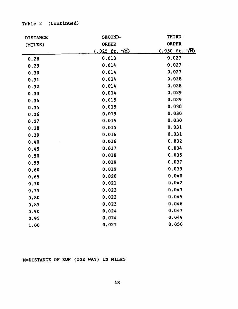
(Continued)Table 2
DISTANCE SECOND- THIRD-(MILES) ORDER ORDER
( .025 ft. --fH) ( .050 ft. -..JM)
0.28 0.013 0.0270.29 0.014 0.0270.30 0.014 0.0270.31 0.014 0.0280.32 0.014 0.0280.33 0.014 0.0290.34 0.015 0.0290.35 0.015 0.0300.36 0.015 0.0300.37 0.015 0.0300.38 0.015 0.0310.39 0.016 0.0310.40 0.016 0.0320.45 0.017 0.0340.50 0.018 0.0350.55 0.019 0.0370.60 0.019 0.0390.65 0.020 0.0400.70 0.021 0.0420.75 0.022 0.0430.80 0.022 0.0450.85 0.023 0.0460.90 0.024 0.0470.95 0.024 0.0491.00 0.025 0.05'0
M=DISTANCE OF RUN (ONE WAY) IN MILES
48

3.7.7 Leveling Procedures to the Reading Mark (RM) of theElectric Tape Gage (ETG) - When leveling to the zero of the ETG,
a section of calibrated steel tape or a specially designed short
rod is held at the center of the RM line. Care must be taken to
ensure that the tape is held plumb and that the zero on the tape
is held stationary. The tape is read in the same way as a rod.
A note is made in the record indicating which of the readings
were made on tape, the type of tape, and the graduation units of
tape
It is preferable that the graduation interval on the tape be the
same as on the rod used in the rest of the section. When the
same interval is not available, all graduation conversions are t/
be recorded and completed on the level record form. This same
procedure may be followed when leveling to vertically set marks.
In those cases when a tape is read below the reading mark (or
vertical mark), the observations are to be entered in proper
order (top wire, middle wire, bottom wire), and entered in the
proper Backsight or Foresight columns (but with a negative sign
to reflect the down shot). The observation is then computed
algebraically with the other observations. Note in Remarks on
the level record form that the observation was a tape shot
observed below the bench mark, i.e., "Tape downw.
3.8 Field Records and Computations - The field notes are
the only reliable record of the measurements and other pertinent
information obtained. The reliability of these records are
always under suspicion unless the records have been entered in
the field book at the time and place of observation. If, for
clarity, an original record is copied, the original and copy are
to be appropriately labeled and submitted together.
The record shall always be made in ink and be as neat and clear
as possible. No erasures shall be made and no correction fluid
49

used. If an entry is found to be in error, it is crossed out
neatly with a single line to retain legibility and the ~orrection
entered immediately above. All corrections are initialed by the
corrector. All computations shall be checked before leaving the
station.
3.8.1 Tabulation and Computation of Second-Order Levels-
The following discussion on recording three-wire leveling will
serve to illustrate the method of recording and also explain some
details on the method of observations.
3.8.1.1 Three-wire procedures - NOAA Form 75-29, PRECISE
LEVELING THREE-WIRE, is a loose-leaf recording form. The forwardrun is recorded on the front side (Figure 10) and the backward
run on the reverse (Figure 11). The first sheet contains infor-
mation on the personnel, rod (type and graduations), and instru-
ment (type, manufacturer, stadia factor, and serial number).Each section is reduced in the lower right hand corner; the re-
corder must check to see that each section closes along with the
cumulative run. The loose-leaf sheets for each station are to be
attached together with the abstract sheet, NOAA Form 76-183.
Computations are checked before forwarding to the appropriate
office.
In defining the difference in elevations for each station leveled
the difference in elevations is to be computed from the computa-
tions in the columns subtitled Thread Reading on NOAA Form 75-29,
at the entries titled Backsights and Foresights. This method is
more precise than using calculations from the values in the col-
umns subtitled Mean. The calculations obtained from the columnssubtitled Mean are an additional check on the difference in ele-
vations for the section run, and must be computed and shown on
the level sheet. Only the quantities computed from the columns
Thread Reading shall be entered at the entries titled Forward Runand Backward Run. The entries shall be transferred to theabstract sheet. .
5'0

I..
I!
J
j
~
~~.'1 -I... ~c ...a u
0
I
ozzoc-
..
"uc
ic -c= ~u,,- :Iu! ~
0°8 Q-,0 -CC -
ZZU C0 - .S-C ~""'~ VCz ~ c
-CZo. % -..~- -"°-JI&I 0 ~
08W_- ...0 .. > - z~c -:,.~ ~,~ ~-1&1 > WWI&I t ~",-. .- ~ .v...~W z~ ~D.. .
~ ~I C~ ... .I 0o L..--C~-CI0"z:
~J;...!.~~...~.
..1.iz.~
z
-<
1&1
~
i
~
~51.
,-.I~..0
I~zv
I~z0;10..~1=..I
fJ.0I~
0.-4
j
.§~&1
.§~~~
.§
i
f.s.s~~~~
A]
Ii~i
jmj~

~ :. I
i :
'C ,..-°5I&. ...}. }.
-8.'i.. c. .. ~c .
0-£~ 0
11~ 0
z
~.Q.'C.W
v
-c.
WI...Z05~~uc.
~
iII
!
I
II
52
T
...I:."I...J
I~~
Icc0Z
I
II
I.,.
r-tr-t
j
.§~.!1~
.§
~
'+010
.§
M
j
f~a
~.-4
~ -
~a
AI
Ii.Hi
IS~!

The instrument stations (not the turning points) are numbered
consecutively as shown in the column headed No. of Station,
thr9ugh the entire level run. The last digits (in rod units) in
the columns headed Thread Reading, Thread Interval, and Sum of
Intervals correspond directly to the rod graduation pattern and
are estimated to tenths of the rod unit (e.g., half millimeters
for rods graduated in half centimeter units, or millimeters for
rods in full centimeter units). The entries in the columns
headed Mean are carried one place further than the readings
themselves.
,The column headed Thread Interval shows the interval between
the upper and middle thread readings and the middle and lower
readings. The comparison of the upper and lower thread intervals(half intervals) serves two functions. The first, an indication
of the presence of observational blunders, is exhibited by the
difference betWeen the two intervals. The difference must agree
within three units (of the last estimated digit) for readings on
a O.5-centimeter (graduated) rod, two units for readings on a
O.Ol-meter rod, two units for readings on a O.Ol-yard rod, and
five units for readings on a O.Ol-foot rod. If the agreement is
riot met on the first attempt, all three threads should be reread.
If agreement is still not obtained, the instrument should be
off-leveled and releveled in place, and the setup reobserved.
The thread interval should not be forced. Nonzero agreement
(within the allowable tolerance) is not to be confused withinaccurate readings. It is a function of the resolution of the
rod, instrument, and the distance between the two.
The second function of the comparison of half intervals is to
offer a short method for meaning the three thread readings. It
allows the recorder to use the fact that the difference of the
upper and lower half intervals, when divided by three, is thecorrection to be applied (with proper sign) to the middle thread
53

It:. is then notedreading in order to give the mean of the three.
in the Mean column.
The length of a section is co~uted by converting the total Sum
of Intervals for the forward run (backsights and foresights) to
rod units, multiplying by the instrument stadia factor (normally
100 or 333), and then converting to kilometers or miles and
noting the result in the Distance block on NOAA Form 75-29.
Example procedures for recording three-wire leveling, including
the computation of section elevation difference and length, are
shown in Figures 10 and 11.
3.8.1.2 Abstract of precise leveling, - NOAA Form 76-183
(Figures 12 and 13) shall be completed and submitted for each
second-order, class I level run. The headings on the form areself-explanatory. Each abstract sheet shall show the separate
results of each running over each section (including rejected
sections), the mean difference, the divergence, the length of th.
section, the designation of each section, the cumulative diver-
gence and distance of each bench mark from ~he staff or ETG, and
the total distance (all spurs) of levels run. Rejected runs are
designated by an R placed beside the rejected number.
The field elevations of each bench mark are computed above the
zero of the staff or the reference relative to the RH of the
ETG. except at Great Lakes network stations where the field
elevations are computed from the published elevation of the PBM.
To convert the starting elevation of the staff rod step or PBM
from feet to meters, multiply feet by 0.3048, exactly, to obtain
meters.
Sections of leveling at each station are arranged in order along
the line from the staff or ETG toward the last bench mark to be
leveled. A majority of the bench marks to be leveled shall
constitute the main line of leveling. Spur leveling shall be
S4

"E
"-
~~
~
"I:~~~n~
'-l~~~
~-S
n-
l
~
~~
~
-1
~
Q~Q~
~.,
~~
~
-fIi..ai!
.
~
~"-(
~
~
I~GGJ
.-4
r~
:g
oS
~-
11-1
~I~.GJ~~
~
j~4.J
~i~~~tGJ.-4~la
~


listed following the bench mark on the main line from which the
spur departs. Proper notation indicating the spur leveling shall
be made in the Remarks column.
The computation of a line of levels is a progressive calculation
and to have all the sections in their proper order will not only
facilitate the computation, but will make errors in the computed
elevations much less likely to occur. All entries on the abstract
per~aining to spur lines shall be boxed in on the form with the
notation Spur made in the Remarks column.
If staff or ETG reading mark movement in excess of 0.020 ft.
(relative to the PBM) is indicated by comp~ring current levels
with the preceding levels, another level run shall be performed.
It shall be performed immediately from the staff or ETG reading
mark to a minimum of three marks (including the PBM) in ocder to
verify the movement.
3.8.2 Tabulation and Computation of Third-Order Levels-
The equipment and procedures are less precise than for second-
order leveling. only the middle (center) wire is observed and
recorded, the length of the sights are balanced by pacing, the
closure tolerance of 12 mm~ (0.050 ft.~), and non-Invar rods
(metal) may be used.
LEVELING RECORD-TIDE STATION (NOAA Form 76-77) is used to recordall field data obtained at the station where third-order levelingis performed. The station information required on the front of
the recording book must be completed and should include: station
name, station number, chief of party, observer, rodman, and the
instrument and rod(s) (with type, manufacturer, serial number(s)
and rod unit graduation). Page three, Description of Tide Staff,
must be completed fer each level run. New bench mark descrip-
tions or recovery notes need to be recorded on pages ~-13, De-
scription of Bench Mark, or submitted on the appropriate NOAA
forms as detailed in Section 2.12.
57

The levels are run from the staff to each bench mark in line andthen back along the same route (if field conditions warrant, adouble-run spur line is acceptable). Running loops or observingmore than one backsight and one foresight from each individualsetup is unacceptable.
It is necessary to determine the distance of the level run to
ensure closure. The length of sections can be calculated by
taping, stadia, or pacing. Paces are converted to a foot or
meter distance. This information should be recorded on page 5
Remarks, or on the inner margins of the level record pages, in
the Remarks column.
The leveling results are abstracted on the last two pages of the
recording book. Instructions for filling out this abstract are
printed in the book. It is important to convert final meter
elevations to feet (multiply meters by 3.2808399 to obtain feet).
Note the elevation above zero of the staff. Measure the distance
from the zero mark to the staff stop. Under no circumstances
shall the average of the starting elevation and ending elevation
be used. At Great Lakes network stations, the abstract should be
completed with the bench mark and ETG elevations referred to the
published elevation of the PBM. The following examples (Figures
14-18) illustrate the proper recording and abstracting procedures
for leveling with a metric or foot rod.
The use of three-wire leveling procedures for third-order
leveling is encouraged. The procedures are identical to those
discussed in Section 3.8.1.1 for second-order, however, the
equipment and the tolerances conform to third-order standards.
Also, NOAA Form 75-29, PRECISE LEVELING THREE-WIRE, is used forrecording and NOAA Form 76-183, ABSTRACT OF PRECISE LEVELS, isused for the abstract. The three-wire observation method is
considered superior to the single wire for several reasons: the
setup imbalance, maximum sight length, and distances are known;
58

~
~~~/'V'"...J
..11
b
c...
.
j0
~
<:B ~ I. J I... I ~
Ij
i.
ri
~ r ~I ~ ~ -~ 11
~
,.
0-+'
m
+ai~
-.(1-!~.:."~1~.~~
-+~,.1
~
...cd
~
Id
I--~
fi~~~lI
-,~
I~~
I~it
~
.r!
4
..a
~Jl1f!
+IrS~
1---~-~~
+.cQ
~
=
~.
Iwi
~
Iad
~
~~$
'J
~~
~
£
a
~.
59
+c.s
~
~ ,-- ---
+~,-'
--t
...=
~
Id
v
~16"
I.~
~-~c;1 if~ ~~
I~~
~
Q..
~
.a
i~
+1.~
+1 -
.1 ..a~ cd
~
=
...P-P-
-..~
I~~
~
.:r3
."..
...
a
~
""+~cQ
~iii ...~ ~
"".
"i-::1'
J
~~v
~~
~~mf6
~
'#
i~i-:f31a\
~~i~~~
~
,5
]
t
!-:$'r-i
i

i
~
i
I~I~ ~
"
~
(/\
iJ~
.
)!
i
i=
I
~=
!I
T--;r~T-=r]I 41 ~I ~I :!
i
~-,..\4J
~~
£
+.,..
~
.'~!
cdiJ
I
...D
~IIt)
~n
ill
i+~-
...rd
~
.
(
I.I~
I.~
I
~
a
~ ~ I. .. ~ ..i_. ~I
60
+as.'
I
i'
1
+...
~ +.. fd. =
~~
I~~
I
~~. ~ .:~ . .
H;~~...J. =4 ~ = ~ R.
-Hi\
-]§-~
i~~8f&t
~a
]jI111'\r-1
i

a
=
~
ti"
~~
iB
~~8':' !
~~.J I. ..
1.J! 1211.J~~ !'5-sSill a j JJ
~~jl -.8 JI
7.~i~ ~1~1~ 2 &f ! 'I . a~.J.J .IJ.I
~!il ~!I t1 71- SA.J~ilji!~j~Ao.JI"iJ~~
f l"d1:.J~~.JJisa=o1.3.§ 0
~il.Ji1i~~
61
.. I
.; I
.a ~
~ i~
~ l~ts "0
~i~1~.~!~-:s°i
I ~IJ
!]!., .. P--a
ati:ao.J:!a~~!
~ T.
~ ~ ~ ~~I I I i~ ~~ I '
I \/Ii -I ,
.~ I01 . . .. ..
~ ~ . .
;~!~~I CZ:I ~I! tJ1111 . .i~ c{)jl ' ,(}
""1 -i
~tO\J. . . ....~..
Im~~I~i
ii4.i.

~
~
Ii
~
4:~.<{;:r
~
+ I + I."'. ~...a.-= j-=
,
~
~ r1m" =: cd cdg ~ = .1
62
~
m~ rd ~8 ~ =1
] ~rEn+ I~ ~~..I~.: . ~ ""' ":1 .1
, ~
j
.a.J
~~
:s
~
J
J~
i
:§
i
~
~
~
J
3=

i
~.
§
--r;u.~
f~~
Lj~
~~, .9
gj ~
.85.0
iI-iiI'
~
! Jr~
t
~rj..~
~~ .i~~ Ii 0 d
..! I-- -~i '-t: 'I. -, ~i ~
~! "-1--&',. III &J ~! ~~ t dO l' 0
.1 i.f, "'"-. . -
il <J:I cD:
j f. ~A! (IVi
'J-.5:!1~.a; 'S .~.A e ~.o~.. SoSe;-; ~='9~-e-di !~J.J&-3s. ~.!!I
f-'"&~s .~~'J~-3~':8 ;;'=---1:3 3:13 ... ;J
E 81. 11 .'~~J.1 :;~t.sl oSs. ~] I~ ~~ .J:§!~ ~.8 ~~~a ~11j8i.J.-1 f-G~j~ ~ a..J I-a ~.."8-.sI"8-w ~.Il...
18~~"~.~~'.Q-;8;~1
~:~.i~1i.J~..1.J j-a.s~
A~ ~I0 01of, ~I
. .. .
~I9:
I :
i (j;1i !II vii i
1\11
~q
~0,...
\
,
~~I. O!(')! of .
-~
~i?
~~"'! .~I. I~IiJl ~~I~ (jl o!~ (! II
.0~.
'63
1
I
I
I
I
~ I"8 .~ !
~ 11.:J :~ 1~.s .10-=~!2-.!I':tl~."a=~-B .§
~~II
j!il31:i.8t-a:a~-,-.5.i4!
oS "&
! !~i !: : I i
5~1$! I I,.' ' I _
I I~ .j -
. 9! ~ 191!~! J!t \ J i Io~UQ ~ .i I ~-.~ Id Id
;~~~ !
I~~~ I5 ~ ~71 I
-4:~ cQ ~ .~~.s.
;:IiuL..0
I
if
IE.~~.
.I.J
~Bm
Mf!
~
I
~
1
i
ItU
~
~11
:§
~
i
A.~I
.,0:
i I:

the three ,wire reading provides a check whereby blunders can be
quickly corrected; and closure can be accurately determined.
3.8.3 Closure Tolerance (2nd- and 3rd-order) - If all
leveling errors could be eliminated, section runnings would
always agree. However, since this is not possible, tolerances
have been set to ensure that accepted runnings disagree by no
more than an amount consistent with the precision of the pre-
scribed leveling method. When multiple runs of a section dis-
agree by more than the tolerance, blunders or excessive system-atic errors may have occured, and the section shall be rerun.
3.8.3.1 Closure procedure - Whenever a section is double-
run, check that the difference between the two levelings agreewithin the tolerance for the order and class of the survey.
a. Compute the difference between the two levelings.
Because they are opposite in sign, this is the backward run plus
the forward run. As a matter of convenience, the divergence is
opposite in sign from the difference.
b. Compute the tolerance for the distance leveled, K.
It is T x;fC, in millimete,rs, where T is the factor for the order
and class of the survey (6 mm.nkfor second-order, class I, and
12 mm~for third-order), and K is the one-way distance (shortestif more than one) in kilometers. For example, if the distance
leveled is 1.6 km, and the survey is second-order, class I, then:
Double-run Tolerance - 6 mm x~ - %7.6 mm
c. If the divergence from step a is within the toler-ance from step b, the 'section is closed; additional runs are not
required unless staff/bench mark movement is determined. If the
divergence exceeds the tolerance, relevel and recheck the ~ection
6-4

to satisfy two criteria: (1) that all runs likely to contain
blunders or systematic errors are rejected, and (2) that at least
one forward and one backward run are acceptable. Use the reject-
ion procedure, given below, to determine statistically unreliable
runs.
d. When re1eve1ing to close the section, alternate the
direction of leveling to maintain an equal number of forward and
backward runs. If systematic error persists in the leveling, the
mean of all the elevation differences may be biased in favor of
the majority direction. Equalizing the number of runs in each
direction prevents this bias.
3.8.3.2 ~ield check of third-order leveling - The following
procedures are to be utilized in the field check of third-order
levels. They need not be submitted unless verifying a blunder or
systematic errors in the level run. Computations shall be docu-
mented on any of the blank pages in the level book or on a separ-
ate piece of paper forwarded with the level book.
Checking the closure of a leveling section using aExample:rod.
Distance - 258 ft. (from Figure 14)BM 2799C to BM 2799D
258 ft. x 1 mi./5280 ft. - 0.05 mi
the closure tolerance for a oneUsing Table 2 for third-order,setup section is %0.007 ft.
Compute the difference between the two elevation differences:
(from Figure 16)(II II II \
Forward run BM 2799C to BM 2799D +3.382 ft.
Backward run BM 2799D to BM 2799C .-3.37_5. ft.
+0.007 ft.
65

The difference, +0.007 ft. (or divergence, -0.007 ft.), is within
the one setup section tolerance obtained from Table 2 (to.O07
ft.).
Example: Checking the closure of a leveling section using a
metric rod.
Distance = 90 m (from Figure 17)Staff to BM 4293A
90 m x 1 km/1000 m = 0.09 km
Using Table 2 for third-order, the closure tolerance for a one
setup section is to.0020 m.
Compute the difference between the two elevation differ~noes:
-0.571 m (from Figure 18)+0.623 m (. . .)
Forward run Staff to BM 4293A
Backward run BM 4293A to Staff+0.052 m
The difference, +0.052 m (or divergence, -0.052 m), exceeds the
one se~up section tolerance obtained from Table 2 (to.0020 m)1
therefore, the run is rejected and requires a rerun of the
section to obtain forward and backward runs whi~h agree within
the allowable limits.
3.8.3.3 Rejection procedu~e - After three or more runs of a
section, check for agreement as follows:
signs.
a. Compute the mean of all runs, disregarding their
Do not include runs with obvious blunders.b. Compute the difference between this mean and each
run.c. Compute the allowable difference from the mean of
more than two runs. It is based on the order and class of the
66

survey, the number of runs which were meaned, and the distance
leveled. The formula is T x-v'f:, where T is the approximate
factor from the following table and K is the section length in
kilometers. For a section less than 0.10 km in length, K is 0.10
km.
Table 3 Tolerance T factors for closing multiple runs
Third-Order
(mm)Number of
Runs
Second-Order
Class I (min)8.
9.
9.
10.
10.
11.
4.4.4.5.5.5.
34567.8
Reject any run outside the allowable differenced.
from the mean.e. Check the remaining runs to see if there is at
least one forward and one backward. If there is, and none were
reje~ted in step d, the section is closed. If one was rejected,compute a new mean with the remaining runs and return to step b.
If only runs in one direction remain, relevel the section in the
opposite direction and begin again at step a.
Notice that certain runs, rejected when the number of runs werethree or four, may now be accepted when the total number increases.
This is because the accuracy of the mean improves with a larger
sample of data; i.e., it becomes easier to recognize when a run
is different enough to be considered a blunder.
Example: Assume the following second-order, class I differences,
in elevation for a section 1.6 km in distance~
67
44
34
95
,40
,70
.00
2
,6
9
,1
3
,5
1
6
6
9
6
1

F +1.4473 m
B -1.4420 m
F +1.4523 m
B -1.4430 m
F +1.4441 m
Mean 1.44574 m
(from the table) c t4.96 mm~- t6.27 mm
Allowable
Allowable range - 1.44574 m f 0.00627 m
= 1.43947 m. 1.45201 m
Therefore, reject the 1.4523 run
New mean and ranqe-(1.4473 + 1.4420 + 1.4430 + 1.4441)
4
= 1.44410 m
Allowable (from the table) = t4.66 mm ~= tS.89 mm
Allowable range = 1.44410 m f 0.00589 m
= 1.43821 m - 1.44999 m
No rejections
If, for any reason, a run is rejected for any cause other than
excessive divergence from the indiscriminate mean of all the runs
for that section, the reason for rejection shall be clearly
stated in the remarks.
3.9 Special Cases: Water Crossings, Precise ReciprocalLeveling, and Unbalanced Sights - Terrain and leveling conditions
68

often force leveling parties to use other than standard proceq-
ures to accomplish their mission. Three methods for overcoming
certain obstacles are outlined in the order of quality of their
results (and the magnitude of the obstacle they overcome).
3.9.1 Water Crossings - Special methods requiring reci-
procal observations and special equipment have been developed for
determining elevation differences for offshore station platforms
and/or to extended level lines across spans whe~e the distance
exceeds the maximum tolerable sight length ,for standard level-
ing procedures. These methods are used to increase accuracy by
minimizing the error in the collimation of the instrument and
refraction of the atmosphere, and by eliminating the effect of
the curvature of the earth.
(1969) and Schomaker &The method, which is detailed in Berry
Berry (1981), requires:
a. two observation stations,
b. four level instrwnents (Zeiss Ni2) mounted on two
specially designed tribrachs,c. four rotating optical wedges, and
d. two specially designed Invar rods and targets.
This system has proven itself on projects involving sights of
more than 4 km (2.5 mi.) with first-order results.
3.9.2 Precise Reciprocal Leveling - Simultaneous reciprocal
observations are made at each of two points. The success-of this
method, like all reciprocal levelinq, depends on the equality of
the refraction over the line in opposite directions. To secure
this equality, the lines of siqht at both ends should be about
equal, the instrument (at both ends) should be at approximately
the same heiqht, and the lines of siqht should have the hiqhest
69

practical clearance over land and water. For water crossinqs up
to 600 m (about 2,000 ft.), this method is desiqned to obtain
second-order accuracy.
Two instruments (equipment with optical micrometers) with known
acceptable collimation errors and two level rods (each equipped
with a target) are set up as shown in Figure 19. The graduation
uni ts of the plate micrometers are to be compatible with the rod
unit graduations.
Each observer directs the far rodman by radio (or suitable visual
means). The target is positioned in line with the center cross
hair of the instrument and wi thin the range of the micrometer
such that the optical micrometer is at about one-half its
vertical rotation range. The target heights are then recorded.Each observer reads the close rod (be sure to check minimum
focus) and records that reading. S~ultaneous readings on the
far rod, using the micrometer only, are conducted every 30
seconds until ten readinqs have been obtained. The micrometer
readings and the beginning and ending time of the readings are
recorded. This completes half the observations in the set
(run 1). The mean of the differences observed from each side is
one observed difference between the bench marks.
The observers then change places, taking their instruments with
them, but leaving the tripods and rods in place. The reading
sequence is repeated in order to obtain another 10 readings
(run 2). This completes one set of reciprocal observations.
The final rod readings are the target heights plus the average
micrometer readings. Individual differences in elevation vary
considerably. This is because the readings have not been
corrected for instrument error, earth's curvature, or variations
of refraction. The observing program and computation procedures
are so arranged, however, that these effects are minimized in the
~an of the runs.
70

71
QI-"dU
CI?
~0z:
0+'
Q\

The final elevation difference for a set of observations is the
mean of the two runs. The mean of a run is determined as in
standard leveling procedures. The distance is determined by
reading the three cross hairs directly on the far rod from one of
the setups (visibility conditions may require use of the target
to make these readings), or by scaling from a map. At stations
where more than one set of reciprocal observations are required,
the final elevation difference will be the mean of paired sets of
observations retained after rejections required by the closure
tolerance. Specific observation requirements will be specified
in project Instructions or contract documents.
3.9.3 Unbalanced Sights - For staffs positioned up to ISO m
or about 500 ft. offshore, unbalanced sights may be used. Since
curvature errors do not cancel in a non-simultaneous, non-reciprocal leveling observation, the total correction to the
offshore rod reading is the a1gebraic sum of the collimation and
curvature corrections.
The collimation error in the instrument is determined by runninga collimation check just before the unbalanced setup. The col-
limation check must be submitted with the leveling data. The
correction to the offshore rod reading would be the value times
the imbalance (offshore distance minus land distance). Thecurvature corrections are computed from the imbalance, As, andthe mean radius of the earth, r: -tAs2/2r), where r = 6,378,000
m. Three wires shall always be recorded (even for third-orderlevels with excessive sight lengths). All attempts will be madeto follow the precautions to minimize refraction. Specific ob-
servation requirements also will be specified in Project Instruc-
tions or contract documents for unbalanced sight~.
72

REFERENCES
Balazs, Emory I. and Gary M. Young. Corrections applied to the
National Geodetic Survey to precise leveling observations. NOAA
Technical Memorandum NOS NGS 34. National Ocean Survey, National
Oceanic and Atmospheric Administration, Rockville, MD, June 1982,
12 pp.
Berry, Ralph M. The Zeiss apparatus for crossing water spans in
precise leveling. Miscellaneous Paper 69-6. u.s. Lake Survey,Detroit, MI, October 1969, 53 pp.
Bossler, John D. Standards and specifications for geodetic
control networks. Federal Geodetic Control Committee.
Rockville, MD, September 1984, 29 pp.
Floyd, Richard P. Geodetic bench marks. NOAA Manual NOS NGS 1.
National Geodetic Survey, National Ocean Survey, National Oceanic
and Atmospheric Administration, Rockville, MD, September 1978,
52 pp.
Jordan, William, Egger~, and Max Kneissl. Handbuch derVermessungskunde, Vol. III. J.B. Metzlersche Verlagsbuchhandlung,Stuttgart, 1956.
Pfeifer, Ludvik and Nancy L. MOrrison. Input formats and
specifications of the National Geodetic Survey data base. Volume
II. Vertical control data, Federal Geodetic Control Committee,
NOAA Manual NOS NGS 2, National Geodetic Survey, National Ocean
Survey, National Oceanic and Atmospheric Administration,
Rockville, MD, 1980 (reprinted 1982).
Schomaker, M. Christine and Ralph M. Berry. Geodetic leveling.
NOAA Manual NOS NGS 3. National Geodetic Survey, National Ocean
Survey, National Oceanic and Atmospheric Administration,
Rockville, MD, August 1981.
73
Top Related