


Languages
Pages
Legal


T-BERD® 950User’s Guide
November 2000
Copyright 2000 © Acterna®20400 Observation Drive, Germantown, Maryland 20876 -4023 USA
USA 1-800-638-2049 • +1-301-353-1550 • FAX +1-301-353-9216Canada 1-888-689-2165 • +1-905-812-7471 • FAX +1-905-812-3892
www.acterna.com
50-14950-01, Rev. G
Formerly TTC and WWG

Specifications, terms, and conditions are subject to change without notice.All trademarks and registered trademarks are the property of their respective companies.

T-BERD 950 User ’s Guide
Getting Technical Assistance iii
Getting Technical Assistance
If you need assistance or have questions related to the use of this product, call or email the Acterna’s (formerly TTC and WWG) Technical Assistance Center (TAC) for customer support.
During off hours, you can leave a voice mail message; send an email to [email protected] (in Europe, [email protected]); or submit your question using our on-line Technical Assistance Request form at www.acterna.com.
Acterna Contacts
Region Phone Number Hours of Operation
Americas 1-800-638-2049 M-F, 8:00 a.m. to 8:00 p.m., EST
Europe, Africa, and Mid-East
+800 882 85822 (European Freephone)
+44 (0) 118 975 9696 (Acterna UK)
+49 (0) 6172 59 11 00 (Acterna Germany)
+33 (0) 1 39 30 24 24 (Acterna France)
M-F, 8:30 a.m. to 5:00 p.m., GMT
Asia and the Pacific +852 2892 0990 (Hong Kong)
+8610 6833 7477 (Beijing-China)
M-F, 9:00 a.m. to 5:30 p.m.

T-BERD 950 User ’s Guide
iv Acterna Contacts
T-BERD 950 User’s Guide
Table of Contents v
Table of Contents
Getting Technical Assistance. . . . . . . . . . . . . . . . . . . . . . . . . iii
Acterna Contacts . . . . . . . . . . . . . . . . . . . . . . . . . . . . . . . . . . . . . iii
Chapter 1 Introduction . . . . . . . . . . . . . . . . . . . . . . . . . . . . . . . . . . . . . . 1
About this Guide . . . . . . . . . . . . . . . . . . . . . . . . . . . . . . . . . . . . . . . 2
Typographical Conventions . . . . . . . . . . . . . . . . . . . . . . . . . . . . . 2
Using This Guide. . . . . . . . . . . . . . . . . . . . . . . . . . . . . . . . . . . . . . 3
Features and Capabilities . . . . . . . . . . . . . . . . . . . . . . . . . . . . . 4
Chapter 2 Instrument Setup and Description . . . . . . . . . . . . . 5
Instrument Setup . . . . . . . . . . . . . . . . . . . . . . . . . . . . . . . . . . . . . . 6
Modes of Operation . . . . . . . . . . . . . . . . . . . . . . . . . . . . . . . . . . . 7
Terminate Mode . . . . . . . . . . . . . . . . . . . . . . . . . . . . . . . . . . . . . . 7
Drop and Insert (D&I) Mode . . . . . . . . . . . . . . . . . . . . . . . . . . . . 8
Dual Monitor (Mon) Mode . . . . . . . . . . . . . . . . . . . . . . . . . . . . . . 8
Line Loop Back (LLB) Mode . . . . . . . . . . . . . . . . . . . . . . . . . . . . 8
Self Loop Mode . . . . . . . . . . . . . . . . . . . . . . . . . . . . . . . . . . . . . . . 9
Front Panel Controls, Indicators, and Connectors . . . .9
Keypad . . . . . . . . . . . . . . . . . . . . . . . . . . . . . . . . . . . . . . . . . . . . . 14
Left Side Panel Controls and Connectors . . . . . . . . . . . . 14
Using the PCMCIA Card Slot . . . . . . . . . . . . . . . . . . . . . . . . . . 16
Right Side Panel Controls and Connectors . . . . . . . . . . 16
Rear Panel . . . . . . . . . . . . . . . . . . . . . . . . . . . . . . . . . . . . . . . . . . . 18
Battery Operation . . . . . . . . . . . . . . . . . . . . . . . . . . . . . . . . . . . . . 19
Charging Batteries . . . . . . . . . . . . . . . . . . . . . . . . . . . . . . . . . . . 19
Battery Replacement Procedure . . . . . . . . . . . . . . . . . . . . . . . 20

T-BERD 950 User ’s Guide
vi Table of Contents
Preventive Maintenance . . . . . . . . . . . . . . . . . . . . . . . . . . . . . . 21
Exterior Inspection . . . . . . . . . . . . . . . . . . . . . . . . . . . . . . . 22
Exterior Cleaning . . . . . . . . . . . . . . . . . . . . . . . . . . . . . . . . 22
Replacing the Fuse . . . . . . . . . . . . . . . . . . . . . . . . . . . . . . . . . . . 22
Chapter 3 Large Graphical Display Operation . . . . . . . . . . . 25
Main Display Controls . . . . . . . . . . . . . . . . . . . . . . . . . . . . . . . . 26
Large Graphical Display LEDs . . . . . . . . . . . . . . . . . . . . . . . . . 26
Views Keys. . . . . . . . . . . . . . . . . . . . . . . . . . . . . . . . . . . . . . . . . . 26
Scroll and Page Keys . . . . . . . . . . . . . . . . . . . . . . . . . . . . . . . . . 27
Help Key . . . . . . . . . . . . . . . . . . . . . . . . . . . . . . . . . . . . . . . . . . . . 27
Softkeys Controls . . . . . . . . . . . . . . . . . . . . . . . . . . . . . . . . . . . . 28
Softkeys . . . . . . . . . . . . . . . . . . . . . . . . . . . . . . . . . . . . . . . . . . . . 28
Edit Softkey . . . . . . . . . . . . . . . . . . . . . . . . . . . . . . . . . . . . . 28
Increase or Decrease Value Softkeys . . . . . . . . . . . . . . . 29
Clear, Home, and End Softkeys . . . . . . . . . . . . . . . . . . . . 29
Large Graphical Display . . . . . . . . . . . . . . . . . . . . . . . . . . . . . . 30
Home View. . . . . . . . . . . . . . . . . . . . . . . . . . . . . . . . . . . . . . . . . . 30
Title Bar . . . . . . . . . . . . . . . . . . . . . . . . . . . . . . . . . . . . . . . . 30
Selection Area . . . . . . . . . . . . . . . . . . . . . . . . . . . . . . . . . . . 31
Prompting Area . . . . . . . . . . . . . . . . . . . . . . . . . . . . . . . . . . 31
Softkeys . . . . . . . . . . . . . . . . . . . . . . . . . . . . . . . . . . . . . . . . 32
Setup View . . . . . . . . . . . . . . . . . . . . . . . . . . . . . . . . . . . . . . . . . . 32
Title Bar . . . . . . . . . . . . . . . . . . . . . . . . . . . . . . . . . . . . . . . . 32
Selection Area . . . . . . . . . . . . . . . . . . . . . . . . . . . . . . . . . . . 33
Prompting Area . . . . . . . . . . . . . . . . . . . . . . . . . . . . . . . . . . 33
Softkeys . . . . . . . . . . . . . . . . . . . . . . . . . . . . . . . . . . . . . . . . 33
Results View . . . . . . . . . . . . . . . . . . . . . . . . . . . . . . . . . . . . . . . . 33
Title Bar . . . . . . . . . . . . . . . . . . . . . . . . . . . . . . . . . . . . . . . . 34
Display Area . . . . . . . . . . . . . . . . . . . . . . . . . . . . . . . . . . . . 35
Prompting Area . . . . . . . . . . . . . . . . . . . . . . . . . . . . . . . . . . 35
Softkeys . . . . . . . . . . . . . . . . . . . . . . . . . . . . . . . . . . . . . . . . 35

T-BERD 950 User ’s Guide
Table of Contents vii
System View . . . . . . . . . . . . . . . . . . . . . . . . . . . . . . . . . . . . . . . . 35
Title Bar . . . . . . . . . . . . . . . . . . . . . . . . . . . . . . . . . . . . . . . . 36
Selection Area . . . . . . . . . . . . . . . . . . . . . . . . . . . . . . . . . . . 36
Prompting Area . . . . . . . . . . . . . . . . . . . . . . . . . . . . . . . . . . 39
Softkeys . . . . . . . . . . . . . . . . . . . . . . . . . . . . . . . . . . . . . . . . 39
Chapter 4 Specifications . . . . . . . . . . . . . . . . . . . . . . . . . . . . . . . . . . . 41
Physical Specifications . . . . . . . . . . . . . . . . . . . . . . . . . . . . . . . 42
T1 Specifications . . . . . . . . . . . . . . . . . . . . . . . . . . . . . . . . . . . . . 43
Chapter 5 T1 Task Navigated Testing (TNT) . . . . . . . . . . . . . . 47
Testing with the T-BERD 950 . . . . . . . . . . . . . . . . . . . . . . . . 48
Comparing Manual Setup to TNT . . . . . . . . . . . . . . . . . . . . 48
TNT Task Mode, Setup, and Results. . . . . . . . . . . . . . . . . . . . 48
Performing T1 BERT Turn-up in CSU Emulation . . . . .49
Performing T1 DDS Turn-up Test in CSU Emulation . .50
Performing Fractional T1 Turn-up Test in CSU Emulation . . . . . . . . . . . . . . . . . . . . . . . . . . . . . . . . . . . . . 51
Performing T1 Monitor Tests . . . . . . . . . . . . . . . . . . . . . . 53
Manual Setup and Results . . . . . . . . . . . . . . . . . . . . . . . . . . . 54
Test Configuration Examples . . . . . . . . . . . . . . . . . . . . . . . . . 54
TNT Example . . . . . . . . . . . . . . . . . . . . . . . . . . . . . . . . . . . . . . . . 55
Manual Setup Example . . . . . . . . . . . . . . . . . . . . . . . . . . . . . . . 57
Using the Manual to Setup Configurations . . . . . . . . . . . 59
Chapter 6 T1 Manual Test Setup . . . . . . . . . . . . . . . . . . . . . . . . . . 61
Setting Up Manual T1 Test . . . . . . . . . . . . . . . . . . . . . . . . . . . 62
Setting Up the Home View . . . . . . . . . . . . . . . . . . . . . . . . . . . . 62
Setting Up the T1 Interface View . . . . . . . . . . . . . . . . . . . . . . . 62
Setting DDS Loop Codes . . . . . . . . . . . . . . . . . . . . . . . . . 68
Setting T1 Loop Codes . . . . . . . . . . . . . . . . . . . . . . . . . . . 70
T-BERD 950 User ’s Guide
viii Table of Contents
Using HDSL and Repeater Commands Softkeys . . . . .75
Editing User-Programmable Fields . . . . . . . . . . . . . . . . . 77
Setting Up a Voice Test . . . . . . . . . . . . . . . . . . . . . . . . . . . . . . . 79
Setting Up the T1 Test Type View . . . . . . . . . . . . . . . . . . . . . . 80
T1 BERT Patterns . . . . . . . . . . . . . . . . . . . . . . . . . . . . . . . . 81
Editing the User Pattern n Field . . . . . . . . . . . . . . . . . . . . . . . . 87
Chapter 7 T1 Test Results . . . . . . . . . . . . . . . . . . . . . . . . . . . . . . . . . 89
Test Results Display. . . . . . . . . . . . . . . . . . . . . . . . . . . . . . . . . . 90
LCD . . . . . . . . . . . . . . . . . . . . . . . . . . . . . . . . . . . . . . . . . . . . . . . . 90
RESULTS I and II Display Controls and Indicators. . . . . . . . 91
Equipment Receiver Results Controls and Indicators. . . . . .91
T1 Test Results . . . . . . . . . . . . . . . . . . . . . . . . . . . . . . . . . . . . . . . 92
Summary Category . . . . . . . . . . . . . . . . . . . . . . . . . . . . . . . . . . . 92
Alarm/Status LEDs . . . . . . . . . . . . . . . . . . . . . . . . . . . . . . . . . . . 93
Interface Category Results . . . . . . . . . . . . . . . . . . . . . . . . . . . . 94
Test Type Category . . . . . . . . . . . . . . . . . . . . . . . . . . . . . . . . . . 97
Signal Category Results . . . . . . . . . . . . . . . . . . . . . . . . . . . . . . 98
Time Category Results. . . . . . . . . . . . . . . . . . . . . . . . . . . . . . . 100
Performance Category Results. . . . . . . . . . . . . . . . . . . . . . . . 101
Alarm Category Results . . . . . . . . . . . . . . . . . . . . . . . . . . . . . . 103
Chapter 8 Printer Operation . . . . . . . . . . . . . . . . . . . . . . . . . . . . . . 105
Printer Configuration . . . . . . . . . . . . . . . . . . . . . . . . . . . . . . . . 106
Printing . . . . . . . . . . . . . . . . . . . . . . . . . . . . . . . . . . . . . . . . . . . . 106
Manual Print Screen . . . . . . . . . . . . . . . . . . . . . . . . . . . . . . . . . 106
Timed Print Screen . . . . . . . . . . . . . . . . . . . . . . . . . . . . . . . . . . 107
Non-Volatile Storage of Prints. . . . . . . . . . . . . . . . . . . . . . . . . 107
User Interface Configuration Requirements . . . . . . . . . . . . . 108
Chapter 9 Options . . . . . . . . . . . . . . . . . . . . . . . . . . . . . . . . . . . . . . . . . 111
Available Options . . . . . . . . . . . . . . . . . . . . . . . . . . . . . . . . . . . . 112
T-BERD 950 User ’s Guide
Table of Contents ix
DDS LL Option . . . . . . . . . . . . . . . . . . . . . . . . . . . . . . . . . . . . . . . . . 113
Option Description . . . . . . . . . . . . . . . . . . . . . . . . . . . . . . . . . . . 114
Option Specifications . . . . . . . . . . . . . . . . . . . . . . . . . . . . . . . . 115
Option Messages . . . . . . . . . . . . . . . . . . . . . . . . . . . . . . . . . . . 116
Setting Up TNT . . . . . . . . . . . . . . . . . . . . . . . . . . . . . . . . . . . . . . 117
Performing DDS Service Turn-up. . . . . . . . . . . . . . . . . . . . . . 117
Troubleshooting DDS Service. . . . . . . . . . . . . . . . . . . . . . . . . 118
Monitoring DDS Service. . . . . . . . . . . . . . . . . . . . . . . . . . . . . . 119
Setting Up Manual DDS LL Test . . . . . . . . . . . . . . . . . . . . . . . . 120
Setting Up the DDS LL Interface View . . . . . . . . . . . . . . . . . 120
Setting Up the DDS LL Test Type View . . . . . . . . . . . . . . . . 123
Test Results . . . . . . . . . . . . . . . . . . . . . . . . . . . . . . . . . . . . . . . . . 125
Status/Alarm LEDs . . . . . . . . . . . . . . . . . . . . . . . . . . . . . . . . . . 126
Summary Category Results . . . . . . . . . . . . . . . . . . . . . . . . . . 126
Interface Category Results . . . . . . . . . . . . . . . . . . . . . . . . . . . 127
Signal Category Results . . . . . . . . . . . . . . . . . . . . . . . . . . . . . 127
Alarm Messages . . . . . . . . . . . . . . . . . . . . . . . . . . . . . . . . . . . . 128
Frame Relay Option . . . . . . . . . . . . . . . . . . . . . . . . . . . . . . . . . . . 131
Option Description . . . . . . . . . . . . . . . . . . . . . . . . . . . . . . . . . . . 132
Operating Modes. . . . . . . . . . . . . . . . . . . . . . . . . . . . . . . . . . . . 132
Terminate Mode . . . . . . . . . . . . . . . . . . . . . . . . . . . . . . . . 132
Monitor Mode . . . . . . . . . . . . . . . . . . . . . . . . . . . . . . . . . . . 133
Option Specifications . . . . . . . . . . . . . . . . . . . . . . . . . . . . . . . . 134
Option Messages . . . . . . . . . . . . . . . . . . . . . . . . . . . . . . . . . . . 134
Setting Up TNT . . . . . . . . . . . . . . . . . . . . . . . . . . . . . . . . . . . . . 134
Performing T1 Interface Frame Relay Turn-up . . . . . . . . . . 135
Performing T1 Interface DDS Frame Relay Turn-up. . . . . . 137
Performing DDS LL Interface Frame Relay Turn-up . . . . . . 138
Performing Frame Relay Monitor Test . . . . . . . . . . . . . . . . . 140

T-BERD 950 User ’s Guide
x Table of Contents
Setting Up Manual Frame Relay Test . . . . . . . . . . . . . . . 141
Setting Up the Interface View . . . . . . . . . . . . . . . . . . . . . . . . . 141
Setting Up the Test Type View . . . . . . . . . . . . . . . . . . . . . . . . 141
Test Results . . . . . . . . . . . . . . . . . . . . . . . . . . . . . . . . . . . . . . . . . 146
Alarm/Status LEDs . . . . . . . . . . . . . . . . . . . . . . . . . . . . . . . . . . 147
Summary Category Results . . . . . . . . . . . . . . . . . . . . . . . . . . 148
Interface Category Results . . . . . . . . . . . . . . . . . . . . . . . . . . . 148
Test Type Category Results . . . . . . . . . . . . . . . . . . . . . . . . . . 148
Performance Category Results. . . . . . . . . . . . . . . . . . . . . . . . 151
Alarm Messages . . . . . . . . . . . . . . . . . . . . . . . . . . . . . . . . . . . . 152
ISDN PRI Option . . . . . . . . . . . . . . . . . . . . . . . . . . . . . . . . . . . . . . . 155
Option Description . . . . . . . . . . . . . . . . . . . . . . . . . . . . . . . . . . . 156
ISDN Services . . . . . . . . . . . . . . . . . . . . . . . . . . . . . . . . . . . . . . 156
Operating Modes. . . . . . . . . . . . . . . . . . . . . . . . . . . . . . . . . . . . 157
Monitor Mode . . . . . . . . . . . . . . . . . . . . . . . . . . . . . . . . . . . 157
Terminate Mode . . . . . . . . . . . . . . . . . . . . . . . . . . . . . . . . 157
Option Specifications . . . . . . . . . . . . . . . . . . . . . . . . . . . . . . . . 158
Setting Up TNT . . . . . . . . . . . . . . . . . . . . . . . . . . . . . . . . . . . . . . 158
Performing T1 Interface ISDN PRI Turn-up . . . . . . . . . . . . . 158
Performing ISDN PRI Monitor Test . . . . . . . . . . . . . . . . . . . . 160
Setting Up Manual ISDN Test . . . . . . . . . . . . . . . . . . . . . . . 161
Setting Up the Interface View . . . . . . . . . . . . . . . . . . . . . . . . . 161
Setting Up the Test Type View . . . . . . . . . . . . . . . . . . . . . . . . 162
Using ISDN and Call Control Features . . . . . . . . . . . . . 167
Placing a Call . . . . . . . . . . . . . . . . . . . . . . . . . . . . . . . . . . . 168
Answering a Call . . . . . . . . . . . . . . . . . . . . . . . . . . . . . . . . 169
Interpreting D-Channel Display . . . . . . . . . . . . . . . . . . . 170
Test Results . . . . . . . . . . . . . . . . . . . . . . . . . . . . . . . . . . . . . . . . . 171
Summary Category Results . . . . . . . . . . . . . . . . . . . . . . . . . . 172
Interface Category Results . . . . . . . . . . . . . . . . . . . . . . . . . . . 172
T-BERD 950 User ’s Guide
Table of Contents xi
Test Type Category Results . . . . . . . . . . . . . . . . . . . . . . . . . . 172
Sample Test Type Results . . . . . . . . . . . . . . . . . . . . . . . 175
ISDN Q.931 Cause Codes . . . . . . . . . . . . . . . . . . . . . . . 176
Signaling Option . . . . . . . . . . . . . . . . . . . . . . . . . . . . . . . . . . . . . . 179
Option Description . . . . . . . . . . . . . . . . . . . . . . . . . . . . . . . . . . . 180
Operating Modes. . . . . . . . . . . . . . . . . . . . . . . . . . . . . . . . . . . . 180
Terminate Mode . . . . . . . . . . . . . . . . . . . . . . . . . . . . . . . . 180
Drop & Insert Mode . . . . . . . . . . . . . . . . . . . . . . . . . . . . . 180
Monitor Mode . . . . . . . . . . . . . . . . . . . . . . . . . . . . . . . . . . . 181
Signaling Sequence Types . . . . . . . . . . . . . . . . . . . . . . . . . . . 181
Call Origination Signaling . . . . . . . . . . . . . . . . . . . . . . . . 181
Pre-defined Signaling Sequences . . . . . . . . . . . . . . . . . 182
Manual Dialing Signaling . . . . . . . . . . . . . . . . . . . . . . . . . 182
Call Termination Signaling . . . . . . . . . . . . . . . . . . . . . . . 182
Signaling Trunk Types . . . . . . . . . . . . . . . . . . . . . . . . . . . . . . . 183
Standard (E&M) Signaling . . . . . . . . . . . . . . . . . . . . . . . . 183
Ground Start Signaling . . . . . . . . . . . . . . . . . . . . . . . . . . . 184
Loop Start Trunk Type Signaling . . . . . . . . . . . . . . . . . . 187
User-Defined Trunk Type Signaling . . . . . . . . . . . . . . . . 189
Programmable Signaling Elements . . . . . . . . . . . . . . . . 189
Option Specifications . . . . . . . . . . . . . . . . . . . . . . . . . . . . . . . . 191
Option Messages . . . . . . . . . . . . . . . . . . . . . . . . . . . . . . . . . . . 192
Setting Up TNT . . . . . . . . . . . . . . . . . . . . . . . . . . . . . . . . . . . . . . 192
Performing T1 Interface PBX/Switch Turn-up . . . . . . . . . . . 192
Performing T1 Monitor Tests . . . . . . . . . . . . . . . . . . . . . 193
Setting Up Manual Signaling Test . . . . . . . . . . . . . . . . . . . 194
Setting Up the Interface View . . . . . . . . . . . . . . . . . . . . . . . . . 195
Setting Up the Test Type View . . . . . . . . . . . . . . . . . . . . . . . . 196
Test Results . . . . . . . . . . . . . . . . . . . . . . . . . . . . . . . . . . . . . . . . . 201
Summary Category Results . . . . . . . . . . . . . . . . . . . . . . . . . . 201
Test Type Category Results . . . . . . . . . . . . . . . . . . . . . . . . . . 201
T-BERD 950 User ’s Guide
xii Table of Contents
PCM TIMS Option . . . . . . . . . . . . . . . . . . . . . . . . . . . . . . . . . . . . . 203
Option Description . . . . . . . . . . . . . . . . . . . . . . . . . . . . . . . . . . . 204
Operating Modes. . . . . . . . . . . . . . . . . . . . . . . . . . . . . . . . . . . . 204
Terminate Mode . . . . . . . . . . . . . . . . . . . . . . . . . . . . . . . . 204
Drop & Insert Mode . . . . . . . . . . . . . . . . . . . . . . . . . . . . . 204
Monitor Mode . . . . . . . . . . . . . . . . . . . . . . . . . . . . . . . . . . . 205
Test Routines. . . . . . . . . . . . . . . . . . . . . . . . . . . . . . . . . . . . . . . 205
Holding Tone Test . . . . . . . . . . . . . . . . . . . . . . . . . . . . . . 205
Variable Tone Test . . . . . . . . . . . . . . . . . . . . . . . . . . . . . . 205
3 Tones Test . . . . . . . . . . . . . . . . . . . . . . . . . . . . . . . . . . . 206
Quiet Test . . . . . . . . . . . . . . . . . . . . . . . . . . . . . . . . . . . . . . 206
Setting Up TNT . . . . . . . . . . . . . . . . . . . . . . . . . . . . . . . . . . . . . . 206
Performing T1 Interface PBX/Switch Turn-up . . . . . . . . . . . 207
Setting Up Manual PCM TIMS Test . . . . . . . . . . . . . . . . . 208
Setting Up the Interface View . . . . . . . . . . . . . . . . . . . . . . . . . 208
Setting Up the Test Type View . . . . . . . . . . . . . . . . . . . . . . . . 209
Front Panel Keys. . . . . . . . . . . . . . . . . . . . . . . . . . . . . . . . . . . . 212
Test Results . . . . . . . . . . . . . . . . . . . . . . . . . . . . . . . . . . . . . . . . . 212
Summary Category Results . . . . . . . . . . . . . . . . . . . . . . . . . . 213
Test Type Category Results . . . . . . . . . . . . . . . . . . . . . . . . . . 213
ISDN BRI Option . . . . . . . . . . . . . . . . . . . . . . . . . . . . . . . . . . . . . . . 217
Option Description . . . . . . . . . . . . . . . . . . . . . . . . . . . . . . . . . . . 218
U Interface . . . . . . . . . . . . . . . . . . . . . . . . . . . . . . . . . . . . . . . . . 219
Interface Between NT and the Network . . . . . . . . . . . . 219
Operating Modes. . . . . . . . . . . . . . . . . . . . . . . . . . . . . . . . . . . . 220
LT BERT Mode . . . . . . . . . . . . . . . . . . . . . . . . . . . . . . . . . 220
NT1 BERT Mode . . . . . . . . . . . . . . . . . . . . . . . . . . . . . . . . 221
NT1/TE Mode . . . . . . . . . . . . . . . . . . . . . . . . . . . . . . . . . . 222
Manual and EOC Loopbacks . . . . . . . . . . . . . . . . . . . . . . . . . 223
External Interface Requirements . . . . . . . . . . . . . . . . . . . . . . 223
Option Specifications . . . . . . . . . . . . . . . . . . . . . . . . . . . . . . . . 224
T-BERD 950 User ’s Guide
Table of Contents xiii
Setting Up TNT . . . . . . . . . . . . . . . . . . . . . . . . . . . . . . . . . . . . . 225
Performing Line Qualification Test . . . . . . . . . . . . . . . . . . . . . 226
Placing and Receiving Circuit Calls . . . . . . . . . . . . . . . . . . . . 226
Placing and Receiving Packet Calls . . . . . . . . . . . . . . . . . . . 228
Setting Up Manual BER Test . . . . . . . . . . . . . . . . . . . . . . . . 230
Setting Up the Interface View . . . . . . . . . . . . . . . . . . . . . . . . . 231
Setting Up the Test Type View . . . . . . . . . . . . . . . . . . . . . . . . 232
Setting Up Manual ISDN Test . . . . . . . . . . . . . . . . . . . . . . . 234
Setting Up the Interface View . . . . . . . . . . . . . . . . . . . . . . . . . 234
Setting Up the Test Type View . . . . . . . . . . . . . . . . . . . . . . . . 235
Setting Up ISDN Packet and Advanced Test Type View . . 240
Editing CALL USER DATA . . . . . . . . . . . . . . . . . . . . . . . 241
Setting Up Advanced Call Configurations . . . . . . . . . . . 242
Configuring ISDN Control . . . . . . . . . . . . . . . . . . . . . . . . 243
Placing a Call . . . . . . . . . . . . . . . . . . . . . . . . . . . . . . . . . . . 243
Answering a Call . . . . . . . . . . . . . . . . . . . . . . . . . . . . . . . . 244
Interpreting D-Channel Display . . . . . . . . . . . . . . . . . . . 245
Test Results . . . . . . . . . . . . . . . . . . . . . . . . . . . . . . . . . . . . . . . . . 246
Status and Alarm LEDs . . . . . . . . . . . . . . . . . . . . . . . . . . . . . . 247
Summary Category Results . . . . . . . . . . . . . . . . . . . . . . . . . . 247
Interface Category Results . . . . . . . . . . . . . . . . . . . . . . . . . . . 248
Test Type Category Results . . . . . . . . . . . . . . . . . . . . . . . . . . 248
X.25 Test Type Category Results . . . . . . . . . . . . . . . . . 252
ISDN Q.931 Cause Codes . . . . . . . . . . . . . . . . . . . . . . . . . . . 255
10 BaseT/Ethernet Option . . . . . . . . . . . . . . . . . . . . . . . . . . . . 259
Option Description . . . . . . . . . . . . . . . . . . . . . . . . . . . . . . . . . . . 260
Operating Modes. . . . . . . . . . . . . . . . . . . . . . . . . . . . . . . . . . . . 260
PING Testing . . . . . . . . . . . . . . . . . . . . . . . . . . . . . . . . . . . . . . . 260
Traffic Generation Testing . . . . . . . . . . . . . . . . . . . . . . . . . . . . 261
External Interface Requirements . . . . . . . . . . . . . . . . . . . . . . 261

T-BERD 950 User ’s Guide
xiv Table of Contents
Option Specifications . . . . . . . . . . . . . . . . . . . . . . . . . . . . . . . . 261
Setting up TNT Testing . . . . . . . . . . . . . . . . . . . . . . . . . . . . . . 262
Setting up Manual Testing. . . . . . . . . . . . . . . . . . . . . . . . . . . 263
Setting up the Interface View . . . . . . . . . . . . . . . . . . . . . . . . . 264
Setting up the Test Type View . . . . . . . . . . . . . . . . . . . . . . . . 264
Test Results . . . . . . . . . . . . . . . . . . . . . . . . . . . . . . . . . . . . . . . . . 266
Status and Alarm LEDs . . . . . . . . . . . . . . . . . . . . . . . . . . . . . . 267
Summary Category Results . . . . . . . . . . . . . . . . . . . . . . . . . . 268
Interface Category Results . . . . . . . . . . . . . . . . . . . . . . . . . . . 268
Test Type Category Results . . . . . . . . . . . . . . . . . . . . . . . . . . 271
Performance Category Results. . . . . . . . . . . . . . . . . . . . . . . . 273
Chapter 10 Acterna Customer Services . . . . . . . . . . . . . . . . . 275
Overview . . . . . . . . . . . . . . . . . . . . . . . . . . . . . . . . . . . . . . . . . . . . 276
Customer Service Locations . . . . . . . . . . . . . . . . . . . . . . . . 276
Services . . . . . . . . . . . . . . . . . . . . . . . . . . . . . . . . . . . . . . . . . . . . . 277
Instrument Service . . . . . . . . . . . . . . . . . . . . . . . . . . . . . . . . . . 277
Product Enhancement Group . . . . . . . . . . . . . . . . . . . . . . . . . 278
Test Systems Field Engineering and Installation. . . . . . . . . 278
Technical Training. . . . . . . . . . . . . . . . . . . . . . . . . . . . . . . . . . . 279
Warranty Information . . . . . . . . . . . . . . . . . . . . . . . . . . . . . . . . 280
Equipment Return Instructions . . . . . . . . . . . . . . . . . . . . . . 282
Appendix A Repeater Loop Codes . . . . . . . . . . . . . . . . . . . . . . . . . 285
Appendix B Glossary . . . . . . . . . . . . . . . . . . . . . . . . . . . . . . . . . . . . . . . 293
Index . . . . . . . . . . . . . . . . . . . . . . . . . . . . . . . . . . . . . . . . . . . . . . . . . . . . . . . . . 299

T-BERD 950 User ’s Guide
Figures xv
Figures
Figure 1 • D&I Mode Paths 8
Figure 2 • LLB Mode Paths 9
Figure 3 • Front Panel 10
Figure 4 • Left Side Panel 15
Figure 5 • Right Side Panel View 17
Figure 6 • Rear Panel View 19
Figure 7 • Main Display and Controls 26
Figure 8 • Home View 31
Figure 9 • Interface Setup View 32
Figure 10 • Interface Results View 34
Figure 11 • System View 36
Figure 12 • Home View 55
Figure 13 • TNT Setup View 56
Figure 14 • TNT Results View 57
Figure 15 • Home View 62
Figure 16 • T1 Setup Interface View 63
Figure 17 • Voice Interface Setup View 79
Figure 18 • T1 Test Type View 80
Figure 19 • Two-Line Display Area 90
Figure 20 • T-BERD 950 Print Screen 107
Figure 21 • DDS LL TNT Setup View 117
Figure 22 • DDS LL Setup Interface View 120
Figure 23 • DDS LL Setup Test Type View 124
Figure 24 • DDS LL Results Test Type View 126
Figure 25 • TTC Test Frame Format 133

T-BERD 950 User ’s Guide
xvi Figures
Figure 26 • Frame Relay Setup Interface View 141
Figure 27 • Frame Relay Setup Test Type View 142
Figure 28 • Frame Relay Test Type Results 147
Figure 29 • ISDN PRI TNT Setup View 158
Figure 30 • ISDN PRI Setup Interface View 162
Figure 31 • ISDN PRI Setup Test Type View 162
Figure 32 • ISDN PRI D-Channel Display 171
Figure 33 • ISDN PRI D-channel Backup Results 175
Figure 34 • ISDN PRI Call Status Results 176
Figure 35 • Signaling Setup Interface View 195
Figure 36 • Signaling Setup Test Type View 196
Figure 37 • PCM TIMS Setup Interface View 208
Figure 38 • PCM TIMS Setup Test Type View 210
Figure 39 • PCM TIMS Test Type Results View 213
Figure 40 • ISDN BRI S/T and U Reference Points 220
Figure 41 • ISDN BRI LT Terminate Mode 221
Figure 42 • ISDN BRI NT1 Terminate Mode 221
Figure 43 • ISDN BRI NT1/TE in Terminate Mode 222
Figure 44 • ISDN BRI TNT Setup View 225
Figure 45 • ISDN BRI BERT Setup Interface View 231
Figure 46 • ISDN BRI BERT Setup Test Type View 232
Figure 47 • ISDN BRI Setup Interface View 234
Figure 48 • ISDN BRI Test Type Setup View 235
Figure 49 • ISDN BRI D-Channel Display 245
Figure 50 • ISDN BRI Test Type Results 249
Figure 51 • ISDN BRI Call Status and Call Failure Report 252
Figure 52 • ISDN BRI X.25 Results 252
Figure 53 • ISDN BRI X.25 Call Results 253
T-BERD 950 User ’s Guide
Figures xvii
Figure 54 • 10BaseT TNT Setup View 262
Figure 55 • 10BaseT Setup Interface View 264
Figure 56 • 10BaseT Setup Test Type View 265
Figure 57 • 10BaseT Results Test Type View 267

T-BERD 950 User ’s Guide
xviii Figures
T-BERD 950 User ’s Guide
Tables xix
Tables
Table 1 • Front Panel Controls, Indicators, and Connectors 11
Table 2 • Keypad Special Functions 14
Table 3 • Left Side Panel Description 15
Table 4 • Right Side Panel Controls and Connectors 17
Table 5 • Physical Specifications 42
Table 6 • T1 Specifications 43
Table 7 • T1 Loop Code Originating Messages 46
Table 8 • T1 BERT Turn-up 50
Table 9 • T1 DDS Turn-up 51
Table 10 • Fractional T1 BERT Turnup Task 52
Table 11 • T1 Monitor Tests 53
Table 12 • AUTO Framing 64
Table 13 • Repeater Type 71
Table 14 • Commands and Addresses for Repeaters 73
Table 15 • Command Sets 73
Table 16 • HDSL Equipment 74
Table 17 • AUTO Pattern Example 84
Table 18 • EQUIPMENT Key/LEDs Settings 91
Table 19 • Status/Alarm LEDs for T1 Interface 93
Table 20 • Interface Category Results 94
Table 21 • DDS Control Codes 96
Table 22 • Test Type Category Results 97
Table 23 • Signal Category Results 99
Table 24 • Time Category Test Results 100
Table 25 • Performance Category Results 101
T-BERD 950 User ’s Guide
xx Tables
Table 26 • Alarm Category Results 103
Table 27 • RJ-45 Pin Assignments 114
Table 28 • Option Specifications 115
Table 29 • Option Messages 116
Table 30 • DDS LL BERT Turnup 118
Table 31 • DDS LL Interface DDS Troubleshooting 119
Table 32 • DDS LL Monitor 119
Table 33 • DDS LL Interface Results 127
Table 34 • DDS LL Signal Results 128
Table 35 • DDS LL Alarms 129
Table 36 • Option Specifications 134
Table 37 • T1 Interface — Frame Relay Turn-up 136
Table 38 • T1 Interface — DDS Frame Relay 137
Table 39 • DDS LL Interface — Frame Relay Turn-up 139
Table 40 • Frame Relay Monitor Tests 140
Table 41 • Frame Relay Test Type Results 149
Table 42 • Frame Relay Performance Results 152
Table 43 • Frame Relay Alarms 153
Table 44 • ISDN PRI Turn-up (PBX Emulation) 159
Table 45 • ISDN PRI Monitor Test 161
Table 46 • ISDN PRI Incoming Call Activities 169
Table 47 • ISDN PRI Test Type Results 173
Table 48 • ISDN PRI Results Reports Cause Codes 176
Table 49 • Standard E&M Signaling 184
Table 50 • Ground Start FXS Signaling 184
Table 51 • Ground Start FXO Signaling 185
Table 52 • Ground Start SLC Station Signaling 186
Table 53 • Ground Start SLC Office Signaling 186

T-BERD 950 User ’s Guide
Tables xxi
Table 54 • Loop Start FXS Signaling 187
Table 55 • Loop Start FXO Signaling 188
Table 56 • Loop Start SLC Station Signaling 188
Table 57 • Loop Start SLC Office Signaling 189
Table 58 • Digit Type Symbols for User-Defined Signaling 190
Table 59 • Supervision Event Symbols for User-Defined Signaling 190
Table 60 • Signaling Option Specifications 191
Table 61 • T1 Interface PBX/Switch Turn-up 193
Table 62 • T1 Monitor Tests 194
Table 63 • Signaling Test Type Results 202
Table 64 • T1 Interface PBX/Switch Turn-up 207
Table 65 • PCM TIMS Test Type Results 214
Table 66 • ISDN BRI Loopbacks 223
Table 67 • ISDN BRI Option Connectors 224
Table 68 • ISDN BRI U Interface Specifications 224
Table 69 • ISDN BRI Line Qualification Test 226
Table 70 • ISDN BRI Circuit Calls 227
Table 71 • ISDN BRI Packet Calls 229
Table 72 • ISDN BRI SPID Guess Table 239
Table 73 • Incoming Call Activities 244
Table 74 • Status and Alarm LEDs 247
Table 75 • ISDN BRI Interface Category Results 248
Table 76 • ISDN BRI Test Type Category Results 250
Table 77 • ISDN BRI X.25 Test Type Category Results 253
Table 78 • ISDN BRI Results Reports Q.931 Cause Codes 256
Table 79 • 10BaseT/Ethernet Option Specifications 261
Table 80 • 10BaseT/Ethernet Turn-up 263
Table 81 • Status and Alarm LEDs 268

T-BERD 950 User ’s Guide
xxii Tables
Table 82 • 10BaseT/Ethernet Interface Category Results 269
Table 83 • 10BaseT/Ethernet Test Type Category Results 271
Table 84 • 10BaseT/Ethernet Performance Category Results 273
Table 85 • Teltrend Repeater Command Loop Codes 286
Table 86 • Westell Repeater Command Loop Codes 287
Table 87 • XEL Line Repeater Command Loop Codes 289
Table 88 • PairGain Generic HDSL Command Loop Codes 289
Table 89 • PairGain A2LB HDSL Command Loop Codes 291
Table 90 • Adtran Abbreviated HDSL Command Loop Codes 291
Table 91 • Adtran Standard HDSL Command Loop Codes 292

T
T-BERD 950 User ’s Guide
his chapter is an overview of the contents of this guide and describes the typographical conventions used. Additionally, you will find a brief
description of T-BERD 950 testing features and capabilities.
Chap te r1 Introduction

T-BERD 950 User ’s Guide
About this Guide2 Chapter 1 — Introduction
About this Guide
This guide describes the T-BERD 950, including features, accessories, warnings, and complete installation instructions; maintenance information and troubleshooting techniques; system specifications; warranty, service, and repair information; and terms and conditions of the licensing agreement.
Typographical Conventions
The following format conventions clarify content throughout this guide.
Key names, menu options, and screen prompts appear in boldface. Example: Tab, Start, Enter.
Consecutive or simultaneous keystrokes are indicated with the plus (+) symbol. Example: Ctrl+Alt+Delete.
Special messages or warnings are indicated with the following symbols:
Warning Caution Note/Tip
T-BERD 950 User ’s Guide
About this GuideChapter 1 — Introduction 3
Using This Guide
The T-BERD 950 User’s Guide provides basic operating information for the T-BERD 950 Communications Analyzer.
To help you best use this guide, it is organized as follows:
Chapter 1 — Introduction: Describes the guide conventions and outline of the User’s Guide.
Chapter 2 — Instrument Setup and Description: Describes the T-BERD 950 Communications Analyzer, instrument setup, modes of operation, preventative maintenance, and battery replacement procedures.
Chapter 3 — Large Graphical Display Operation: Describes the operation of the Large Graphical Display.
Chapter 4 — Specifications: Describes the physical specifications of the Communications Analyzer.
Chapter 5 — T1 Task Navigated Testing (TNT) Overview: Describes the Task Navigated Testing (TNT) feature.
Chapter 6 — T1 Manual Test Setup: Describes the setup for T1 BER Testing and includes Smart Repeater test setups and commands.
Chapter 7 — T1 Test Results: Describes the available test results, the category of the test results, and the test type with which it is associated.
Chapter 8 — Printer Operation: Describes the printer functions of the T-BERD 950.
Chapter 9 — Options: Contains subsections for each of the following options:
– DDS-LL Option: Describes the DDS LL option, specifications, TNT and manual test setups, plus results.
– Frame Relay Option: Describes the Frame Relay option, specifications, TNT and manual test setups, plus results.
– ISDN PRI Option: Describes the ISDN Primary Rate Interface (PRI) option, specifications, TNT and manual test setups, plus results.

T-BERD 950 User ’s Guide
Features and Capabilities4 Chapter 1 — Introduction
– Signaling Option: Describes the Signaling option, specifications, TNT and manual test setups, plus results.
– PCM TIMS Option: Describes the Pulse Code Modulation Transmission Impairment Measurement Set (PCM TIMS) option, specifications, TNT and manual test setups, plus results.
– ISDN BRI Option: Describes the ISDN Basic Rate Interface (BRI) option, specifications, TNT and manual test setups, plus results.
– 10BaseT/Ethernet Option: Describes the 10BaseT Ethernet option, specifications, TNT and manual test setups, plus results.
Chapter 10 — Acterna Customer Services: Contains information on Acterna customer services, general warranty information, and service and repair information.
Appendix A — Repeater Loop Codes Appendix B — Glossary Index
Features and Capabilities
Designed to make routine test setup simple and intuitive, Task Navigated Testing (TNT) guides field service technicians through typical testing scenarios quickly, easily, and accurately. TNT is designed around the tasks and terminology employed by the technician. Basic T1 TNT configurations are described in “Testing with the T-BERD 950” on page 48.
TNT is for the technician who performs typical field service turnup and troubleshooting procedures. However, for those who encounter non-traditional testing scenarios, the T-BERD 950 is still entirely custom configurable using Manual Setup mode. Either way, the T-BERD 950 can provide full featured testing capabilities based on your needs.
T
T-BERD 950 User ’s Guide
his section describes the T-BERD 950 Communications Analyzerinstrument setup; modes of operation; front, side, and rear panel
connectors and indicators; battery operation; and preventative maintenance.
Chap te r 2 Instrument
Setup and Description

Instrument Setup6 Chapter 2 — Instrument Setup and Description
T-BERD 950 User ’s Guide
Instrument Setup
This section provides you with instructions for how to get your T-BERD 950 up and running.
1. Remove the T-BERD 950 from the shipping container.
Save the container. If the T-BERD 950 requires servicing, use this container to return it to Acterna.
2. Temporarily remove the cover of the T-BERD 950.
Place the T-BERD 950 upright so that it stands on its rubber feet and the handle is at the top. Use both thumbs to push the lid clips inward and to the right simultaneously (to unhinge them from the connector). Pull the lid towards you. Be sure to save the cover.
3. Connect the yellow AC power cord to the T-BERD 950.
The power cable is included with the T-BERD 950 in the shipping container. The AC power connector is on the bottom right side of it.
4. Apply power to the T-BERD 950.
The switch is on the right side of the T-BERD 950.
5. Adjust the contrast of the graphical display to suit you.
The control is located on front panel, to the left of the display. The display appears blank until the contrast is adjusted.
6. Press the SELF LOOP control.
The SELF LOOP control is on lower left corner of the front panel. The SELF LOOP LED illuminates to indicate the T-BERD 950 is receiving its transmitted signal.
7. Check the Status/Alarm LEDs.
The cover is not hinged at the bottom of the T-BERD 950, so to remove the bottom of the cover, simply raise it up from the slots on the bottom.

Modes of OperationChapter 2 — Instrument Setup and Description 7
T-BERD 950 User ’s Guide
Status/Alarm LEDs are located in the upper right corner of the front panel. Verify SIGNAL, FRAME SYNC, PATTERN SYNC and B8ZS LEDs are illuminated green.
Once you complete these procedures, it is safe set up the T-BERD 950 for testing purposes. For additional help, please call Acterna’s Technical Assistance Center (TAC) at 1-800-638-2049.
Modes of Operation
The baseline T-BERD 950 Communications Analyzer is a T1/FT1 Bit Error Rate (BER) test set that offers several options that enable it to become a full-featured, multi-service test instrument. It has two T1 interfaces: T1-LINE and T1-EQUIPMENT. Each interface consists of an independent receiver and transmitter. The interfaces can be configured for various applications.
The T-BERD 950 can operate in four modes:
Terminate Mode
Drop and Insert (D&I) Mode
Dual Monitor (Mon) Mode
Line Loop Back (LLB) Mode
Terminate Mode
This mode separates the transmit and receive sides of a T1 path. The input signal is terminated at the receive side, and a totally independent signal is generated for the output. You can use either the LINE Tx/Rx pair or the EQUIPMENT Tx/Rx pair.
In the event of power loss (i.e., no AC power and no batteries) to the T-BERD 950, the LINE and EQUIPMENT pairs are automatically cross connected to prevent loss of service.
Modes of Operation8 Chapter 2 — Instrument Setup and Description
T-BERD 950 User ’s Guide
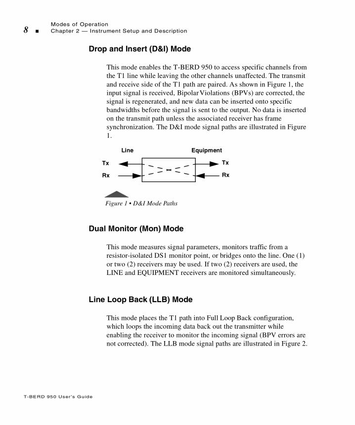
Drop and Insert (D&I) Mode
This mode enables the T-BERD 950 to access specific channels from the T1 line while leaving the other channels unaffected. The transmit and receive side of the T1 path are paired. As shown in Figure 1, the input signal is received, Bipolar Violations (BPVs) are corrected, the signal is regenerated, and new data can be inserted onto specific bandwidths before the signal is sent to the output. No data is inserted on the transmit path unless the associated receiver has frame synchronization. The D&I mode signal paths are illustrated in Figure 1.
Figure 1 • D&I Mode Paths
Dual Monitor (Mon) Mode
This mode measures signal parameters, monitors traffic from a resistor-isolated DS1 monitor point, or bridges onto the line. One (1) or two (2) receivers may be used. If two (2) receivers are used, the LINE and EQUIPMENT receivers are monitored simultaneously.
Line Loop Back (LLB) Mode
This mode places the T1 path into Full Loop Back configuration, which loops the incoming data back out the transmitter while enabling the receiver to monitor the incoming signal (BPV errors are not corrected). The LLB mode signal paths are illustrated in Figure 2.
Line Equipment
Tx
Rx
Tx
Rx

Front Panel Controls, Indicators, and ConnectorsChapter 2 — Instrument Setup and Description 9
T-BERD 950 User ’s Guide
Figure 2 • LLB Mode Paths
Self Loop Mode
When the T-BERD 950 is placed in Self Loop mode (press SELF LOOP key), a set of relays is activated. These relays are designed to pass the incoming signal through the T-BERD 950. The signal path is from Rx LINE to Tx EQUIPMENT, and from Rx EQUIPMENT to Tx LINE. This is the same configuration as for D&I Mode.
If a D&I test is being performed, and the T-BERD 950 is placed in Self Loop mode; the incoming signal still passes through it without interruption. If it is in Terminate Mode, where the configuration is Tx LINE to Rx LINE, the relays have no effect. The relays remain active when the unit loses power or is powered off.
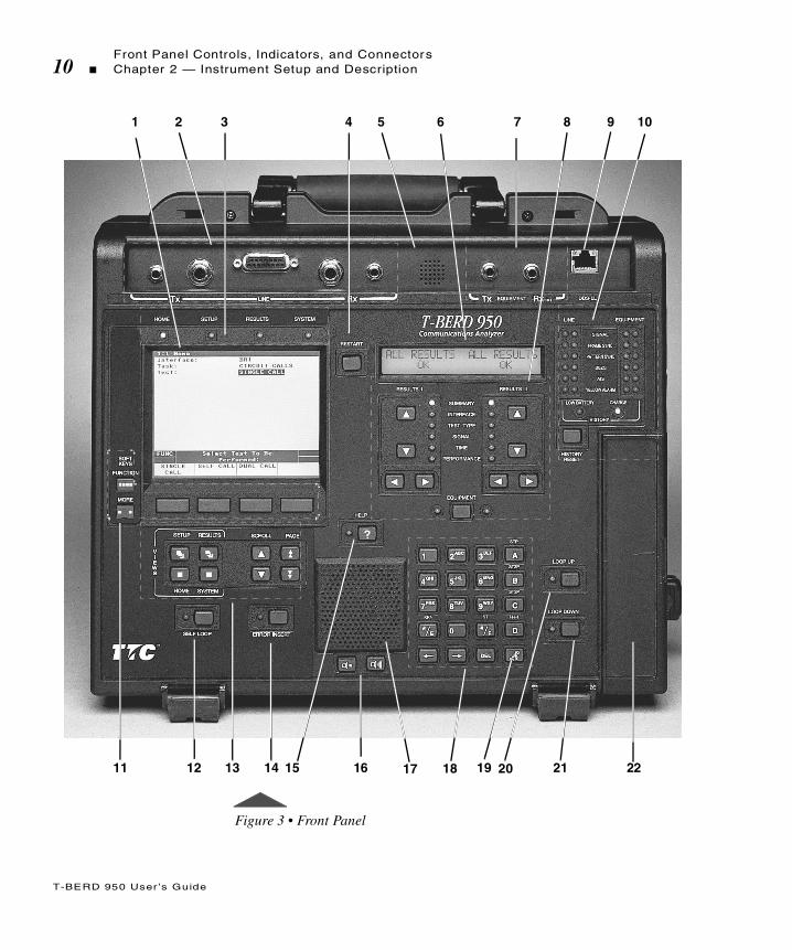
Front Panel Controls, Indicators, and Connectors
The front panel of the T-BERD 950 mainframe is shown in Figure 3 with each control (or control group), indicator, and connector marked with a numbered callout. Table 1 provides a brief description of each control, indicator, and connector referenced to the numbered callouts in Figure 3.
Line Equipment
Tx
Rx
Tx
Rx
Front Panel Controls, Indicators, and Connectors10 Chapter 2 — Instrument Setup and Description
T-BERD 950 User ’s Guide
Figure 3 • Front Panel
1 2 3 4 5 6 7 8 9 10
11 12 13 14 15 17 20 21 2216 18 19

Front Panel Controls, Indicators, and ConnectorsChapter 2 — Instrument Setup and Description 11
T-BERD 950 User ’s Guide
Table 1 • Front Panel Controls, Indicators, and Connectors
No Control Indicator Description
1 Large Graphical Display Shows four unique views:Home — Configures the interface, task, and test to be performed.Setup — Configures the specifics of the selected test.Results — Shows results for the selected test.System — Configures general mainframe and auxiliary settings.
2 T1 LINE Tx and Rx Connectors
Consists of one set of WECO 310 female connectors, one set of Bantam female connectors, and one 15-pin D connector for LINE Tx and Rx. This is also referred to as Primary Side.
3 Large Graphical Display LED
Illuminates to indicate which view is active.
4 RESTART Key Generates a manual test restart and clears all results, including any flashing messages on the Two-Line Display.
5 Microphone Used for Voice testing, activated by the PUSH-TO-TALK key on the keypad.
6 Two-Line Display Shows LINE and EQUIPMENT receiver results. Line receiver results appear unless the EQUIPMENT Key is used to show EQUIPMENT receiver results (see Callout #8). Also shows status and alarm messages.
7 T1 EQUIPMENT Tx and Rx Connectors
Connects one set of Bantam female connectors for the EQUIPMENT Tx and Rx. This is also referred to as Secondary Side.
8 RESULTS I and II Display Area Controls & Indicators
Up/Down Arrow Keys — Selects the results category.Left/Right Arrow Keys — Selects the individual result within the selected category.Category Light Emitting Diodes (LEDs) — Illuminates to indicate the selected category.EQUIPMENT Key — Selects EQUIPMENT channel results for the RESULTS I and II display areas. The LEDs under RESULTS I and II light to indicate that EQUIPMENT channel results are shown. If the LED is off, LINE side results appear.
Front Panel Controls, Indicators, and Connectors12 Chapter 2 — Instrument Setup and Description
T-BERD 950 User ’s Guide
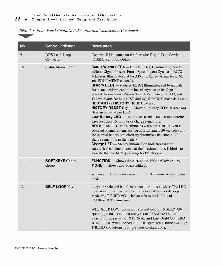
9 DDS Local Loop Connector
Connects RJ45 connector for four wire Digital Data Service (DDS) Local Loop Option.
10 Status/Alarm Group Status/Alarm LEDs — (inside LEDs) Illuminates green to indicate Signal Present, Frame Sync, Pattern Sync, and B8ZS detection. Illuminates red for AIS and Yellow Alarm for LINE and EQUIPMENT channels.History LEDs — (outside LEDs) Illuminates red to indicate that a status/alarm condition has changed state for Signal Present, Frame Sync, Pattern Sync, B8ZS detection, AIS, and Yellow Alarm, for both LINE and EQUIPMENT channels. Press RESTART or HISTORY RESET to clear.HISTORY RESET Key — Clears all history LEDs. It does not clear an active alarm LED.Low Battery LED — Illuminates to indicate that the batteries have less than 15 minutes of charge remaining.NOTE: This LED also illuminates when the T-BERD 950 is powered on and remains on (for approximately 30 seconds) until the internal battery test circuitry determines the amount of charge remaining in the battery.Charge LED — Steady illumination indicates that the battery(ies) is being charged at the maximum rate. It blinks to indicate that the battery is being trickle charged.
11 SOFTKEYS Control Group
FUNCTION — Shows the current available softkey groups.MORE — Shows additional softkeys.
Softkeys — Use to make selections for the currently highlighted field.
12 SELF LOOP Key Loops the selected interface transmitter to its receiver. The LED illuminates indicating self loop is active. When in self loop mode, the T-BERD 950 is isolated from the LINE and EQUIPMENT connectors.
When SELF LOOP operation is turned On, the T-BERD 950 operating mode is automatically set to TERMINATE, the transmit timing is set to INTERNAL and Line Build Out (LBO) is set to 0 db. When the SELF LOOP operation is turned Off, the T-BERD 950 returns to its previous configuration.
Table 1 • Front Panel Controls, Indicators, and Connectors (Continued)
No Control Indicator Description

Front Panel Controls, Indicators, and ConnectorsChapter 2 — Instrument Setup and Description 13
T-BERD 950 User ’s Guide
13 Large Graphical Display Controls Group
VIEWS Control Keys (HOME, SETUP, RESULTS and SYSTEM) — Provide access to the Home, Setup, Results, and System views.
SCROLL Keys — Move one item at a time up or down the list on the current view.
PAGE Keys — Scroll up or down a full screen at a time when PGUP or PGDN appear on the right side of the prompting area.
14 ERROR INSERT Key Inserts a single error or errors at a specified rate. If the key is pressed for more than two (2) seconds, the LED illuminates to indicate that error rates are being inserted.
15 HELP Key Accesses help for the active selection line.
16 VOLUME Keys Controls the volume of the speaker. The left key reduces the volume and the right key increases the volume.
17 Speaker Allows you to hear audible VF tones present (i.e., voice, TIMS tones).
18 Alphanumeric Keypad Consists of a telephone keypad. See Table 2, on page 14, for detailed functions of the special keys.
19 PUSH-TO-TALK Key Activates the microphone feature.
20 LOOP UP Key Activates loop up code transmission. The LED illuminates to indicate loop up code is being transmitted.
21 LOOP DOWN Key Activates loop down code transmission. The LED illuminates to indicate loop down code is being transmitted.
22 Interface Module Slot Provides slot for optional interface module use, such as the Analog 2W/4W or Datacom (DTE/DCE) interface modules.
Table 1 • Front Panel Controls, Indicators, and Connectors (Continued)
No Control Indicator Description
Left Side Panel Controls and Connectors14 Chapter 2 — Instrument Setup and Description
T-BERD 950 User ’s Guide
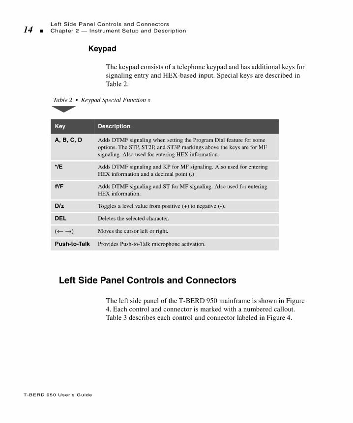
Keypad
The keypad consists of a telephone keypad and has additional keys for signaling entry and HEX-based input. Special keys are described in Table 2.
Left Side Panel Controls and Connectors
The left side panel of the T-BERD 950 mainframe is shown in Figure 4. Each control and connector is marked with a numbered callout. Table 3 describes each control and connector labeled in Figure 4.
Table 2 • Keypad Special Function s
Key Description
A, B, C, D Adds DTMF signaling when setting the Program Dial feature for some options. The STP, ST2P, and ST3P markings above the keys are for MF signaling. Also used for entering HEX information.
*/E Adds DTMF signaling and KP for MF signaling. Also used for entering HEX information and a decimal point (.)
#/F Adds DTMF signaling and ST for MF signaling. Also used for entering HEX information.
D/± Toggles a level value from positive (+) to negative (-).
DEL Deletes the selected character.
(← →) Moves the cursor left or right.
Push-to-Talk Provides Push-to-Talk microphone activation.

Left Side Panel Controls and ConnectorsChapter 2 — Instrument Setup and Description 15
T-BERD 950 User ’s Guide
Figure 4 • Left Side Panel
Table 3 • Left Side Panel Description
No. Control Indicator Description
1 AUX PORT Future use.
2 CONTRAST Adjusts the backlight on the Large Graphical Display. Note: If the contrast is not set properly, the display appears blank.
3 RS-232 PRINT/CONTROL
Connects to the RS-232 side of the printer cable.
4 PCMCIA Card Slot Used for the T-BERD 950 software card.
5 Option Slot Used for the Protocol Services Board (Acterna Part # TB950-PSB).U interface connectors are present, but the ISDN BRI software option (Acterna# TB950-BRI) must be installed to perform ISDN BRI testing. For details see “External Interface Requirements” on page 223.
RS-232 PRINT/CONTROLAUX PORT
CONTRAST
1 2 3 4
5
U Interface
To LTTo NT

Right Side Panel Controls and Connectors16 Chapter 2 — Instrument Setup and Description
T-BERD 950 User ’s Guide
Using the PCMCIA Card Slot
Insert the T-BERD 950 software card.
1. Turn power off.
2. Open the PCMCIA access door, the hinged cover over the port on the right side.
The inside of the door is marked “OPTION - Top Eject” on the left and “SOFTWARE - Bottom Eject” on the right.
3. Insert your software in the bottom slot.
The top slot is for future use.
To remove the PCMCIA software card, press the small release button on the right side of the software slot. Do not try to pull it out.
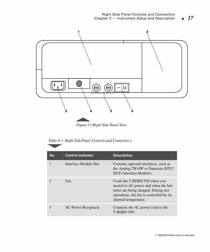
Right Side Panel Controls and Connectors
The right side panel of the T-BERD 950 mainframe is shown in Figure 5. Each control and connector is marked with a numbered callout. Table 4 describes each control and connector referenced to the numbered callouts in Figure 5.
Right Side Panel Controls and ConnectorsChapter 2 — Instrument Setup and Description 17
T-BERD 950 User ’s Guide
Figure 5 • Right Side Panel View
Table 4 • Right Side Panel Controls and Connector s
No. Control Indicator Description
1 Interface Module Slot Contains optional interfaces, such as the Analog 2W/4W or Datacom (DTC/DCE) Interface Modules.
2 Fan Cools the T-BERD 950 when con-nected to AC power and when the bat-teries are being charged. During test operations, the fan is controlled by its internal temperature.
3 AC Power Receptacle Connects the AC power cord to the T-BERD 950.
1 2
3 4 5 6

Rear Panel18 Chapter 2 — Instrument Setup and Description
T-BERD 950 User ’s Guide
Rear Panel
The rear panel of the T-BERD 950 mainframe is shown in Figure 6. As shown in Figure 6, access to the rechargeable batteries is through the battery compartment door. The tilt stand can be adjusted to stand the T-BERD 950 at an angle for easier viewing of the display screens.
4 Interface Module Release Button or Lever
Releases an interface module for removal. To release the installed inter-face module, press the button or pull the lever.
5 AC Line Fuses Contains two 250 Volt, 1 Amp Slo-Blo fuses (LittleFuse p/n 218 001).
6 Power Switch Powers the T-BERD 950 On or Off (I or O).
Table 4 • Right Side Panel Controls and Connectors (Continued)
No. Control Indicator Description

Battery OperationChapter 2 — Instrument Setup and Description 19
T-BERD 950 User ’s Guide
Figure 6 • Rear Panel View
Battery Operation
The T-BERD 950 uses battery power when AC power is not available. It does so by automatically switching over to battery power when AC power is lost. The rechargeable batteries provide between 2 and 4 hours of operating time. Depending on the tests performed and the configuration, the operating time can vary.
Charging Batteries
The batteries are charged whenever the T-BERD 950 is connected to AC power. When Off, the charging time is approximately 3 hours. When the T-BERD 950 is powered On, the number of batteries
Tilt Stand
Battery CompartmentDoor

Battery Operation20 Chapter 2 — Instrument Setup and Description
T-BERD 950 User ’s Guide
charged and the time required to reach full power is determined by the installed options and configuration of the T-BERD 950. To reach full power, recharging may require up to 8 hours.
Battery charging is not supported in some configurations (i.e., Frame Relay and ISDN PRI). To start charging, either power off the T-BERD 950 or select a configuration that supports charging.
Two LEDs are located on the front panel of the T-BERD 950 to indicate the status of the batteries: Charge LED and Low Battery LED.
Charge LED — Illuminates steady to indicate that the batteries are being charged at the maximum charge rate. Blinks to indicate that the batteries are fully charged and the charger is producing a trickle charge to maintain the batteries at a full charge, while the T-BERD 950 is turned Off.
Low Battery LED — Illuminates to indicate that the batteries have less than 15 minutes of charge remaining.
Battery Replacement Procedure
To replace the batteries follow these instructions:
1. Power off the T-BERD 950 and disconnect the AC power cord.
The BATT CHG result (Time Results Category) becomes invalid when the batteries are removed. The batteries must be conditioned to obtain a valid Battery Charge result.
If the current configuration supports battery charging, the batteries can be changed one at a time while the test is in progress without interrupting T-BERD 950 performance. The batteries can be “hot swapped” (i.e., one at a time when T-BERD 950 is powered ON). If you do so, remember that the BATT CHG result (Time Results Category) becomes invalid until the batteries are conditioned.
Battery OperationChapter 2 — Instrument Setup and Description 21
T-BERD 950 User ’s Guide
2. Open the battery compartment door, located on the rear panel of T-BERD 950, by turning the two fasteners ¼ turn counterclockwise.
3. Remove each of the batteries individually. Using the cloth strap, lift the end of the battery away from the contacts.
4. Allow one (1) minute between removal and installation of the batteries to enable the battery capacity measurement to reset.
5. Install the new battery by inserting the contact end first and firmly press down on the end away from the contacts.
6. Close the battery compartment door and secure it by turning the two fasteners ¼ turn clockwise.
Preventive Maintenance
Preventive maintenance on the T-BERD 950 involves two steps: visually inspecting it and cleaning it. The T-BERD 950 should be visually inspected and cleaned as often as operating conditions require.
Battery contacts are offset to prevent incorrect installation.
Condition the batteries to obtain accurate battery capacity readings. (Refer to pag e37 in Chapter 3 for additional information.) Allow the batteries to charge to full capacity prior to operating T-BERD 950 on battery power. The batteries will charge when the unit has AC power.
The accumulation of dirt on the T-BERD 950 can cause overheating and component failure.

Battery Operation22 Chapter 2 — Instrument Setup and Description
T-BERD 950 User ’s Guide
Exterior Inspection
Inspect the external portions of the instrument for damage, wear, and loose or missing parts. Check all parts thoroughly to verify correct operation and performance.
Exterior Cleaning
Loose dust on the outside of the instrument can be removed with a soft cloth. Remove any dirt that remains with a soft cloth dampened in a mild detergent and water solution (e.g., Miller Stephenson Cleaner MS-260).
Use only enough water to dampen the cloth. Any accumulated dust and dirt in the fan input area can be removed with a vacuum.
Replacing the Fuse
The procedure to replace the AC power fuse(s) in the T-BERD 950 is presented below.
1. Power off the T-BERD 950 and disconnect the AC power cord.
2. Remove the fuse holder(s) by turning it ¼ turn counterclockwise while pulling the fuse out of the holder.
Any deficiencies found that could cause personal injury or lead to further damage indicate that the unit should not be used.
Do not use abrasive cleaners on the Large Graphical Display or Two-Line Display screen as the screens could be scratched. Do not get moisture inside the instrument.

Battery OperationChapter 2 — Instrument Setup and Description 23
T-BERD 950 User ’s Guide
3. Insert the replacement fuse (Replace with a fuse of the proper rating and voltage (i.e., T1A/250V). See the label on the bottom of the T-BERD 950 for fuse type.) into the holder and reinstall the fuse holder by turning it ¼ turn counterclockwise.
4. Reconnect the AC power cord.
The fuse holders are located on the right side panel of T-BERD 950, immediately to the left of the Power switch. See item 4 of Figur e5 on page 17.

Battery Operation24 Chapter 2 — Instrument Setup and Description
T-BERD 950 User ’s Guide

T
T-BERD 950 User ’s Guide
his chapter describes the operation of the Large Graphical Displayand the Home, Setup, Results, and System views.
Chap te r3 Large Graphical
Display Operation
T-BERD 950 User ’s Guide
Main Display Controls26 Chapter 3 — Large Graphical Display Operation
Main Display Controls
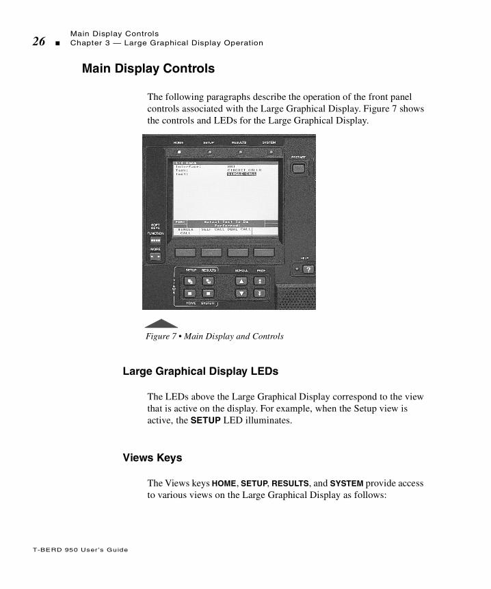
The following paragraphs describe the operation of the front panel controls associated with the Large Graphical Display. Figure 7 shows the controls and LEDs for the Large Graphical Display.
Figure 7 • Main Display and Controls
Large Graphical Display LEDs
The LEDs above the Large Graphical Display correspond to the view that is active on the display. For example, when the Setup view is active, the SETUP LED illuminates.
Views Keys
The Views keys HOME, SETUP, RESULTS, and SYSTEM provide access to various views on the Large Graphical Display as follows:

T-BERD 950 User ’s Guide
Main Display ControlsChapter 3 — Large Graphical Display Operation 27
HOME — Allows you to choose the Test Interface, the Task (TNT or Manual), or the Test Type.
SETUP — Allows you to set the test parameters for the selected Test Interface, Task, and Test Type. Press the SETUP key to access the TNT view, or to change the view to Interface or Test Type.
RESULTS — Allows you to view the test results for these Test Result views: TNT, Summary, Interface, Test Type, Signal, Time, Performance, and Alarms. Press the RESULTS key to view each page.
SYSTEM — Allows you to set general mainframe and auxiliary settings.
Scroll and Page Keys
The SCROLL keys (up and down arrow) are used to scroll through the menu items. The PAGE keys (up and down arrows) are used to page through the display when the PGUP or PGDN indicators appear in the prompting area. If you only have one page, the up arrow PAGE key moves the active selection line to the top of the display. The down arrow PAGE key moves the active selection line to the bottom of the display.
Help Key
The HELP key accesses the available help for the active selection line (shown in reverse video) on the Large Graphical Display. Pressing the key once activates the help function (the LED to the left of the key illuminates) and the available help for the selected menu item will appear. Pressing the HELP key a second time turns off the help function (LED turns off).
If the active selection line is a data entry type field, instructions are provided that explain how to edit the field data. Help must be turned off to edit the field.
T-BERD 950 User ’s Guide
Main Display Controls28 Chapter 3 — Large Graphical Display Operation
Softkeys Controls
The SOFTKEYS Control keys, located to the left of the Large Graphical Display, operate the softkey groups.
The FUNCTION key shows all available softkey groups for the current test and when available, “FUNC” appears on the left side o the Prompting area.
The MORE key shows additional softkeys available within the current softkey group. If there are more than four selections available, “MORE” appears on the left side of the Prompting area.
Softkeys
The softkeys (located immediately below the Large Graphical Display) are used to make selections and activate the functions that appear at the bottom of the Large Graphical Display. The function may be related to a single selection line or to a group of items. The SOFTKEYS Controls (FUNC and MORE) allow you to navigate the softkeys.
In addition to selecting the parameter for your test, the softkeys provide additional functionality based on the type of information you may need to set up your test. Some selections require a numeric or alphanumeric input. Depending on the type of information, softkeys appear allowing you to add or change the information in the field. For example, the Edit softkey appears for you to change numeric information. When selected, the Edit Channels Map popup screen appears.
Edit Softkey
When a channel needs to be selected, the Edit softkey appears. Follow these steps to make your selection.
T-BERD 950 User ’s Guide
Main Display ControlsChapter 3 — Large Graphical Display Operation 29
1. Press Edit to access the Edit Channels screen and the Select/Deselect, Clear All, Abort Changes, and Save & Exit softkeys.
The Edit Channels screen enables configuration of the active channels for both the T1 LINE and T1 EQUIPMENT interfaces (the selected channels are the same for both interfaces).
2. Use the SCROLL keys to move from channel to channel.
The Select/Deselect softkey toggles the channel between active and inactive.
The Clear All softkey deselects all channels.
The Abort Changes softkey exits the Edit Channels screen without making any changes to the existing channel selections and returns you to the previous screen.
3. Press Save & Exit to enter all changes and return to the Setup view.
Increase or Decrease Value Softkeys
The INCREASE VALUE, DECREASE VALUE, and OK softkeys appear when selection lines require a numeric input.
1. Press Increase Value or Decrease Value to increase or decrease the value.
You may also use the keypad to change the value in the field.
2. Press OK to set the value.
Clear, Home, and End Softkeys
These softkeys appear when you need to edit a user-programmable field such as Long User Pattern.
1. Press EDIT softkey and a popup window and additional softkeys appear.
Clear — Clears the field.

T-BERD 950 User ’s Guide
Large Graphical Display30 Chapter 3 — Large Graphical Display Operation
Home — Places the cursor at the beginning of the string.
End — Places the cursor at the end of the string.
2. Press the 1 through 9, or 0 key on keypad to select a character set. The assigned values for that key will appear in the popup window.
3. Press the corresponding number for the character you want to place into the user data information. Press 0 to add spaces if needed.
4. Repeat steps 2 and 3 until your loop code label is complete.
5. Press SCROLL when finished to move to the next selection line.
Large Graphical Display
The four views available on the Large Graphical Display provide easy access to TNT and manual test setups, test configurations, results, and mainframe configurations.
Home View
The Home view (see Figure 8) allows you to select the interface, task, and test you want to perform. The display is divided into four areas: title bar, selection area, prompting area, and softkey descriptions. The following paragraphs describe the function of each area of the Home view.
Title Bar
The top line of the display, called the title bar (see Figure 8), indicates the current view and view type of the Large Graphical Display.

T-BERD 950 User ’s Guide
Large Graphical DisplayChapter 3 — Large Graphical Display Operation 31
Figure 8 • Home View
Selection Area
The selection area enables you to control all of the analyzer configuration selections (see Figure 8). Use the SCROLL keys to navigate the selection area and make the required changes.
Prompting Area
The area on the Large Graphical Display above the softkeys is the prompting area. This area prompts you to perform a specific action based on the current softkey group.
The change takes effect after one second, after exiting the active selection line, or changing the active display screen.
Title Bar
SelectionArea
Interface: T1Task: MANUAL SETUPTest Type: BERT
Prompting
Softkeys
1:1 Home
FUNC Select Task To BePerformed:
MANUALSETUP
Area
T-BERD 950 User ’s Guide
Large Graphical Display32 Chapter 3 — Large Graphical Display Operation
Softkeys
Softkeys show the available choices for each selection line to configure the unit for your test.
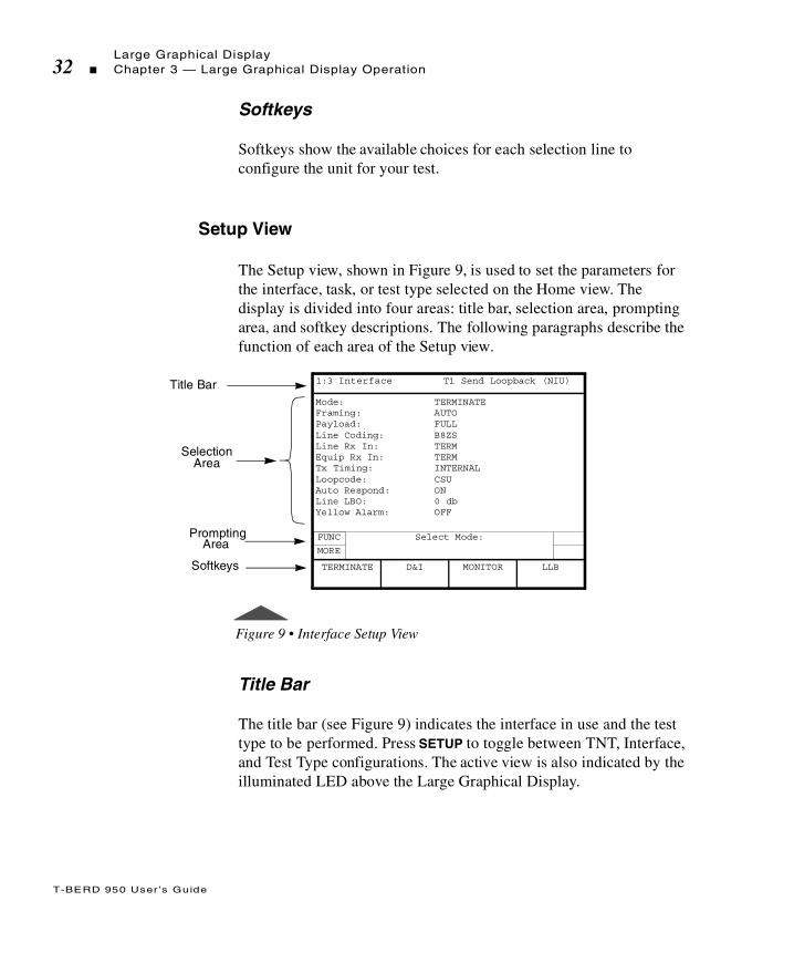
Setup View
The Setup view, shown in Figure 9, is used to set the parameters for the interface, task, or test type selected on the Home view. The display is divided into four areas: title bar, selection area, prompting area, and softkey descriptions. The following paragraphs describe the function of each area of the Setup view.
Figure 9 • Interface Setup View
Title Bar
The title bar (see Figure 9) indicates the interface in use and the test type to be performed. Press SETUP to toggle between TNT, Interface, and Test Type configurations. The active view is also indicated by the illuminated LED above the Large Graphical Display.
Title Bar
SelectionArea
Mode: TERMINATEFraming: AUTOPayload: FULLLine Coding: B8ZSLine Rx In: TERMEquip Rx In: TERMTx Timing: INTERNALLoopcode: CSUAuto Respond: ONLine LBO: 0 dbYellow Alarm: OFF
Prompting
Softkeys
1:3 Interface T1 Send Loopback (NIU)
FUNC
MORE
Select Mode:
D&I MONITOR LLBTERMINATE
Area
T-BERD 950 User ’s Guide
Large Graphical DisplayChapter 3 — Large Graphical Display Operation 33
Selection Area
The selection area enables you to control all of the analyzer configuration selections (see Figure 9)). Use the SCROLL and PAGE keys to navigate the selection area and make the required change.
Prompting Area
The prompting area prompts you to perform a specific action based on the current softkey group (see Figure 9). The PGUP and PGDN indicators appear in this area of the display when the view has more than one page of parameters. Press the PAGE keys to view additional results.
Softkeys
Softkeys show the available choices of each selection line to configure your test (Figure 9). These softkeys appear as choices, or as functions of the selected option.
Results View
The Results view is used to display data for each of the Results categories (i.e., TNT, Summary, Interface, Test Type, Signal, Time, and Performance). In addition, the Results view also lists the date and time the alarm occurred, as well as where the alarm occurred, i.e., the LINE (Primary) or EQUIPMENT (Secondary) side. A sample Interface Results view is shown in Figure 10.
The change takes effect after one second, after exiting the active selection line or changing the active display screen.

T-BERD 950 User ’s Guide
Large Graphical Display34 Chapter 3 — Large Graphical Display Operation
In the event that one Results view is not sufficient to show all of the results for a given category, the PGUP or PGDN indicator will appear on the right side of the prompting area. Use the PAGE keys to scroll the results up and down.
The display is divided into four areas: title bar, selection area, prompting area, and softkey descriptions. The following paragraphs describe the function of each area of the Results view.
Figure 10 • Interface Results View
Title Bar
The title bar displays the view number 1:8 (one of eight) and the current Results view (TNT, Summary, Interface, Test Type, Signal, Time, Performance, or Alarm). Press the RESULTS key to display the next result view.
If all results are within specification for the LINE (Primary) and EQUIPMENT (Secondary) receivers, the message “All Results OK” will appear on the Results view.
Title Bar
SelectionArea
LINEBPVs 0BPV Seconds 0BPV Rate 0Frm Errors 0Frm Er Rate 0Frm Er Sec 0Frm Los Cnt 0Frm Los Sec 0CRC Errors 0CRC Err Sec 0CRC Err Rate 0
Prompting
Softkey
1:3 Interface T1-BERT
PGDN
Press HELP for AdditionalResult Information.
PRINT SCREEN
Area
Descriptions

T-BERD 950 User ’s Guide
Large Graphical DisplayChapter 3 — Large Graphical Display Operation 35
Display Area
The display area shows the list of results for the selected view. The SCROLL keys can be used to scroll up and down through the list of results. The left column lists LINE (Primary) results and the right column lists EQUIPMENT (Secondary) results.
Prompting Area
The prompting area prompts you to perform a specific action based on the current softkey group (see Figure 10 on page 34). The PGUP and PGDN indicators appear in this area of the display when the view has more than one page of results. Press the PAGE keys to view additional results.
Softkeys
Softkeys appear to show the functions available in the Results view.
System View
The System view, shown in Figure 11, provides access to system parameters for the mainframe and other auxiliary functions. The display is divided into four areas: title bar, selection area, prompting area, and softkey descriptions. The following paragraphs describe the function of each area of the System view.

T-BERD 950 User ’s Guide
Large Graphical Display36 Chapter 3 — Large Graphical Display Operation
Figure 11 • System View
Title Bar
The title bar shows the current usage for the System view (Auxiliary).
Selection Area
The selection area is used to configure System functions. Use the SCROLL keys to select the active selection line. Softkeys become available to choose the appropriate configuration. Data entry fields are edited using the keypad.
The following paragraphs provide a description of each System parameter, the choices available, and how to select or edit the parameter. Use the available softkeys in combination with the keypad to edit these parameters.
Date — Displays the date in MM/DD/YY (Month/Day/Year) format.
Time — Displays the time in HH:MM:SS (Hours:Minutes:Seconds) format.
Title Bar
SelectionArea
Date 01/01/99Time: (HH:MM:SS): 00:06:14Timed Test Type: CONTINUOUSMicrophone: PUSH TO TALKDisplay Backlight: ONSystem Information: SoftkeysCondition Battery: NOAlarm Category: NoPower Loss Detect: YESFactory Defaults: NOPrinter Info: HIDEReverse Display: YES
Prompting
Softkeys
1:1 AUX
FUNC Select Date:
PRINTSCREEN
Area
T-BERD 950 User ’s Guide
Large Graphical DisplayChapter 3 — Large Graphical Display Operation 37
Timed Test Type — Selects the type of test to be run. The choices are TIMED or CONTINUOUS. If TIMED is selected the following selection line will appear and must be configured.
Length — Used to enter the amount of time, in HHH:MM (Hours:Minutes) format, that a timed test is to run. A time of zero (0) causes continuous testing.
Microphone — Displays the default microphone operating mode PUSH-TO-TALK.
Display Backlight — Used to vary the length of time the display backlight remains on. Turning off the backlight will extend operating time when operating on battery power. The choices include the following:
AUTO 5 MIN — Turns the backlight on for 5 minutes when a front panel key is pressed. If no front panel key is pressed for a period of 5 minutes, the backlight is turned off.
ON — Turns the backlight on.
OFF — Turns the backlight off.
System Information — Used to show system option and version information. The following softkeys are will appear when System Information is selected:
SOFTWARE VERSIONS — Displays the versions of all software on the system PCMCIA card.
INSTALLED OPTIONS — Displays the hardware and software options currently installed.
UPGRADE CARD INFO — Displays the uninstalled options available on a system PCMCIA card.
Condition Battery — Used to reset the internal fuel gauge maximum capacity to the actual available capacity of the batteries when fully charged. This function should be used whenever the batteries are
When CONTINUOUS is selected the test runs continuously until the RESTART key is pressed or the analyzer is powered off.
T-BERD 950 User ’s Guide
Large Graphical Display38 Chapter 3 — Large Graphical Display Operation
changed, the Battery Performance Index (BPI) or Battery Capacity result is “Invalid,” or the reported capacity of the batteries does not correlate to the actual operating time available.
The battery conditioning cycle can take as long as 12 hours if it is started with fully discharged batteries. During the cycle, the analyzer should be left On and not disturbed. At the end of conditioning, the BPI result is updated to reflect the total capacity of the batteries when fully charged. This capacity will diminish over time as the batteries wear (this is normal). If the BPI is below 50%, you should contact Acterna to obtain new batteries.
Alarm Category — Controls whether a notification message appears on the Two-Line Display when an alarm is detected.
ALERT ON UPDATES — Alerts you to verify the alarm logged in the Alarm Result view.
DON’T ALERT — Disables the notification message but alarms are still logged.
Power Loss Detect — Setting this function to Yes enables detection and incrementing of the Power Loss result on the Time view.
YES — The Power Loss result increments each time the analyzer is powered on. The Power Loss result is cleared when the RESTART key is pressed.
NO — The Power Loss result is not shown.
Factory Defaults — Used to clear the nonvolatile random access memory (NOVRAM). The choices are NO or YES.
YES — Opens confirmation popup window. This window states that the NOVRAM will be reset to the factory defaults and the analyzer will reboot.
Printer Info — Select one of the following choices. Default is HIDE.
HIDE — Hides the options for printer operation.
DISPLAY — Shows other options to set up the print configuration. See “Printer Configuration” on page 106 for more details.

T-BERD 950 User ’s Guide
Large Graphical DisplayChapter 3 — Large Graphical Display Operation 39
Reverse Display — Used to reverse the display from white letters on blue background to blue letters on white background. Default is white on blue. Choices are YES and NO.
Prompting Area
The area on the large graphical display above the softkeys is the prompting area. This area prompts you to perform a specific action based on the current softkey group.
Softkeys
Softkeys appear to show the available choices of each selection line for you to configure the unit for your test.

T-BERD 950 User ’s Guide
Large Graphical Display40 Chapter 3 — Large Graphical Display Operation

T
T-BERD 950 User ’s Guide
his section describes the physical and test specifications of theT-BERD 950.
Chap te r4 Specifications
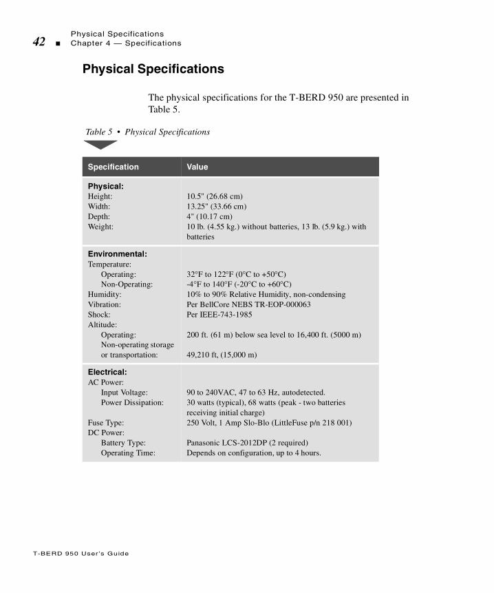
T-BERD 950 User ’s Guide
Physical Specifications42 Chapter 4 — Specifications
Physical Specifications
The physical specifications for the T-BERD 950 are presented in Table 5.
Table 5 • Physical Specifications
Specification Value
Physical:Height:Width:Depth:Weight:
10.5" (26.68 cm)13.25" (33.66 cm)4" (10.17 cm)10 lb. (4.55 kg.) without batteries, 13 lb. (5.9 kg.) with batteries
Environmental:Temperature:
Operating:Non-Operating:
Humidity:Vibration:Shock:Altitude:
Operating:Non-operating storage or transportation:
32°F to 122°F (0°C to +50°C)-4°F to 140°F (-20°C to +60°C)10% to 90% Relative Humidity, non-condensingPer BellCore NEBS TR-EOP-000063Per IEEE-743-1985
200 ft. (61 m) below sea level to 16,400 ft. (5000 m)
49,210 ft, (15,000 m)
Electrical:AC Power:
Input Voltage:Power Dissipation:
Fuse Type:DC Power:
Battery Type:Operating Time:
90 to 240 VAC, 47 to 63 Hz, autodetected.30 watts (typical), 68 watts (peak - two batteries receiving initial charge)250 Volt, 1 Amp Slo-Blo (LittleFuse p/n 218 001)
Panasonic LCS-2012DP (2 required)Depends on configuration, up to 4 hours.
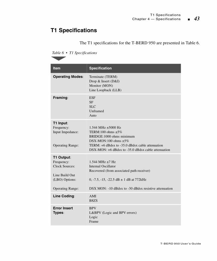
T-BERD 950 User ’s Guide
T1 SpecificationsChapter 4 — Specifications 43
T1 Specifications
The T1 specifications for the T-BERD 950 are presented in Table 6.
Table 6 • T1 Specifications
Item Specification
Operating Modes: Terminate (TERM)Drop & Insert (D&I)Monitor (MON)Line Loopback (LLB)
Framing: ESFSFSLCUnframedAuto
T1 Input:Frequency:Input Impedance:
Operating Range:
1.544 MHz ±5000 HzTERM:100 ohms ±5%BRIDGE:1000 ohms minimumDSX-MON:100 ohms ±5%TERM: +6 dBdsx to -35.0 dBdsx cable attenuationDSX-MON: +6 dBdsx to -35.0 dBdsx cable attenuation
T1 Output:Frequency:Clock Sources:
Line Build Out (LBO) Options:
Operating Range:
1.544 MHz ±7 Hz Internal OscillatorRecovered (from associated path receiver)
0, -7.5, -15, -22.5 dB ± 1 dB at 772kHz
DSX MON: -10 dBdsx to -30 dBdsx resistive attenuation
Line Coding: AMIB8ZS
Error Insert Types:
BPVL&BPV (Logic and BPV errors)LogicFrame

T-BERD 950 User ’s Guide
T1 Specifications44 Chapter 4 — Specifications
Error Insertion Rates:BPV, L&BPV, Logic:Frame:
Single, 1E-3, 1E-61 through 6 and continuous
Loopcodesa: CSU (Loop-up code: 10000; Loop-down code: 100)FAC1 (Loop-up code: 1100; Loop-down code: 11100)FAC2 (Loop-up code: 11000; Loop-down code: 11100)FAC3 (Loop-up code: 100000; Loop-down code: 100)DL-LLB (Data Link - Line Loopback): per ANSI T1.403-1989DL-PLB (Data Link - Payload Loopback): per ANSI T1.403-1989DL-Net (Data Link - Network Loopback): ANSI T1.403-1989V.54 (Fractional T1 only) - PN127Programmable Loop Codes: 3 to 8 bit repeating loop-up and loop-down codes.Latching Loopcodes (DDS only): N signifies a “do not care” value.OCU: N1010101 CSU: N0110001DS0-DP: N0000101 LSI: N1000111NEI: N1000001 DSU: N1110111Alternating Loopcodes (DDS only):N signifies a “do care” value.S signifies: “1” when transmitting or receiving an idle code of a 56 kbps DS0-A signal; “0” when transmitting a DSU loopback of a 56 kbps DS0-A signal; or “do not care” value when transmitting and receiving all other DS0-A signals.OCU: S0101010 OCU+HL96: S0101010HL96NY: S0101010 DSU: S0101100CSU: S0101000 CSU+R: S0101000CSU+2R: S0101000 1ST RPTR: S01010002ND RPTR: S0101000
Indicators: Signal Present, Frame Sync, Pattern Sync, B8ZS Detect, AIS (Alarm Indication Signal) and Yellow Alarm.
Table 6 • T1 Specifications (Continued)
Item Specification

T-BERD 950 User ’s Guide
T1 SpecificationsChapter 4 — Specifications 45
Table 7 lists the Originating Messages that are only available when payload is set to DDS for T1. Similar messages are also set for T1 non-DDS Payload.
Frequency Measurements: Accuracy:Resolution:
± 10 ppm1Hz
Level:Peak to Peak:
Positive and Negative Base to peak:
Positive and Negative Base to peak:
Resolutionb:
20mV to 12.0 V
10 mV to 6.0 V
-48.0 dBdsx to +6.7 dBdsx
±1 dB
Simplex Current:Range:Accuracy:
10 to 207 mA, and under 10 mA±10% or 2mA (whichever is greater)
Wander:Resolution:Accuracy:
1 UI1 UI
a. See Appendix B for additional Loopcodes.b. All level measurement results are based on the peak voltage level of
the input signal.
Table 6 • T1 Specifications (Continued)
Item Specification
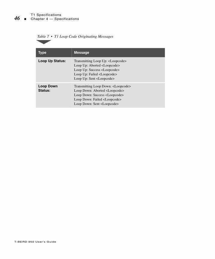
T-BERD 950 User ’s Guide
T1 Specifications46 Chapter 4 — Specifications
Table 7 • T1 Loop Code Originating Messages
Type Message
Loop Up Status: Transmitting Loop Up: <Loopcode> Loop Up: Aborted <Loopcode>Loop Up: Success <Loopcode>Loop Up: Failed <Loopcode>Loop Up: Sent <Loopcode>
Loop Down Status:
Transmitting Loop Down: <Loopcode>Loop Down: Aborted <Loopcode>Loop Down: Success <Loopcode>Loop Down: Failed <Loopcode>Loop Down: Sent <Loopcode>

T
T-BERD 950 User ’s Guide
his chapter describes the TNT functionality for the T1 interface ofthe T-BERD 950. The T-BERD 950 user interface includes two modes
of test operation: TNT and Manual Setup. An explanation of how TNT works, the differences between Manual Setup and TNT modes and how to setup a test using both TNT and Manual Setup modes is discussed in this chapter.
Chap te r5 T1 Task
Navigated Testing (TNT)

T-BERD 950 User ’s Guide
Testing with the T-BERD 95048 Chapter 5 — T1 Task Navigated Testing (TNT)
Testing with the T-BERD 950
1. From the Home view on the T-BERD 950, select the interface (i.e., T1, DDS-LL, and Analog).
2. Define your task.
There are two types of selections: MANUAL SETUP and TNT. Manual Setup is always available. The TNT selections vary depending on the selected interface. Use Manual Setup when you need to perform a non-standard configuration test. TNT tasks primarily address turnup and troubleshooting procedures.
3. Select the specific type of test for the selected procedure.
4. Select SETUP to configure the T-BERD 950 for the chosen application.
5. During the test, press RESULTS to view valuable result information.
Comparing Manual Setup to TNT
In TNT mode, after you press SETUP, the TNT setup view appears. During Manual Setup, after you press SETUP the Interface Setup view appears. While in TNT mode, the TNT Results view is initially shown after you press the Results view key. In manual mode, the Test Type Results view is shown when the Results view is initially pressed.
TNT Task Mode, Setup, and Results
The TNT Setup view provides a condensed number of setup configurations for the chosen tests and tasks selected on the Home view. This enables you to quickly configure the unit because there is a

T-BERD 950 User ’s Guide
Comparing Manual Setup to TNTChapter 5 — T1 Task Navigated Testing (TNT) 49
limited number of configurations. The TNT Results view lists only the most common results to allow you to quickly verify or troubleshoot the circuit.
Table 8 through Table 11 list the available setups and results for each TNT test. Items in parenthesis ( ) are default settings and can be changed using the softkeys to select the appropriate settings for your test. For descriptions of the test setup parameters, see “Setting Up Manual T1 Test” on page 62. For descriptions of all results see “T1 Test Results” on page 92.
Performing T1 BERT Turn-up in CSU Emulation
The objective of a T1 BER test is to perform T1 qualification, such as a QRSS BER test. In the passive loopback mode, you can view various test results while the test is running. This provides a method of isolating the problem to a specific piece of equipment or section of the loop. This is performed as an out-of-service test in TERMINATE mode. Table 8 provides detailed test scenarios, TNT setup items, and test results.
All Setup and Results views can be shown while in TNT mode, by pressing the associated VIEWS control keys (i.e., SETUP and RESULTS). However, TNT Setup and TNT Results view are only available in TNT mode.

T-BERD 950 User ’s Guide
Comparing Manual Setup to TNT50 Chapter 5 — T1 Task Navigated Testing (TNT)
Performing T1 DDS Turn-up Test in CSU Emulation
The objective of this test is to perform DDS qualification such as a 2047 BER test from a T1 access point. This mode lets you view various test results while the test is running. Because you are in D&I
Table 8 • T1 BERT Turn-up
Test TNT Setup Items TNT Results
SEND LOOPBACK(NIU Access)
In this scenario, the T-BERD 950 is being used to generate a loopback code to a device located at either the customer premise (e.g., a CSU) or within the network. The unit sends an HDSL loop code to a doubler or HTU-C, or sends a loop code to an NIU or smart repeater. The technician is typically in control of the test.
Framing (AUTO)Line Coding (ESF)Tx Timing (INTERNAL)Loopcode (CSU)Bert Pattern (QRSS)
BPVsBit ErrorsPat SlipsFrm ErrorsErrored SecCRC ErrorsRcv Freq, HzR Lvl, dBdsx
RECEIVE LOOPBACK(NIU Access)
In this scenario, the T-BERD 950 is being used as a loopback device. Ideally, you are waiting for a loopback code (e.g., a CSU loop) to be sent from a centralized tester or from a test set located in the Central Office (CO). The remote tester is typically in control of the test.
Framing (AUTO)Line Coding (B8ZS)Tx Timing (RECOVERED)Loopcode (CSU)Bert Pattern (AUTO)
BPVsBit ErrorsPat SlipsFrm ErrorsErrored SecCRC ErrorsRcv Freq, HzR Lvl, dBdsx
STRAIGHTAWAY(NIU/DSX access)
In this scenario, the T-BERD 950 is being used at the customer premise, while another test set is located at the far end, typically the CO at a DSX patch panel. Testing and analysis is performed in both directions.
Framing (AUTO)Line Coding (B8ZS)TX Timing (INTERNAL)Bert Pattern (QRSS)
BPVsBit ErrorsPat SlipsFrm ErrorsErrored SecCRC ErrorsRcv Freq, HzR Lvl, dBdsx

T-BERD 950 User ’s Guide
Comparing Manual Setup to TNTChapter 5 — T1 Task Navigated Testing (TNT) 51
mode, the DDS channel under test is out-of-service, while the remaining DS0s (on the T1) are in-service. Table 9 provides detailed test scenarios, TNT setup items, and test results.
Performing Fractional T1 Turn-up Test in CSU Emulation
The purpose of these tests is to perform Fractional T1 qualification such as QRSS BER tests. This mode lets you view various test results while the test is running. Table 10 provides detailed test scenarios, TNT setup items, and test results.
Table 9 • T1 DDS Turn-up
Test TNT Setup Items TNT Results
STRAIGHT-AWAY-DSX
In this scenario, the T-BERD 950 is being used at the CO, while another test set is located at the far end, typically the customer premises NID. Testing and analysis is performed in both directions.
This is the best method to sectionalize and verify a trouble during a turnup than loopback testing.
Framing (ESF)Channel (1)Rate (DS0A56)Line Coding (B8ZS)Insert Side (LINE TX)Insert Payload (OFF) * Bert Pattern (2047)
* User prompted to turn this ON.
BPVsBit ErrorsPat SlipsFrm ErrorsErrored SecCRC ErrorsRcv Freq, HzR Lvl, dBdsx
SEND LOOPBACK-DSX
In this scenario, the T-BERD 950 is used to generate a loop code to a device located at either: (1) the customer premises (such as the CSU/DSU), (2) the local loop (such as a repeater), or (3) within the network (such as an OCU-DP or DS0-DP card).
Framing (ESF)Channel (1)Rate (DS0A56)Line Coding (B8ZS)Insert Side (LINE TX)Insert Payload (OFF) *Loopcode Type (ALTERNATING)Loopcode (DSU)Bert Pattern (2047)
* User prompted to turn this ON.
BPVsBit ErrorsPat SlipsFrm ErrorsErrored SecCRC ErrorsRcv Freq, HzR Lvl, dBdsx
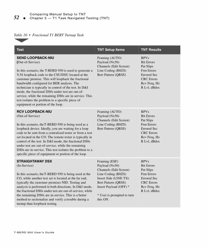
T-BERD 950 User ’s Guide
Comparing Manual Setup to TNT52 Chapter 5 — T1 Task Navigated Testing (TNT)
Table 10 • Fractional T1 BERT Turnup Task
Test TNT Setup Items TNT Results
SEND LOOPBACK-NIU (Out-of-Service) In this scenario, the T-BERD 950 is used to generate a V.54 loopback code to the CSU/DSU located at the customer premise. This will loopback the fractional bandwidth configured for BER analysis. The technician is typically in control of the test. In D&I mode, the fractional DS0s under test are out-of-service, while the remaining DS0s are in-service. This test isolates the problem to a specific piece of equipment or portion of the loop.
Framing (AUTO)Payload (Nx56)Channels (Edit Screen)Line Coding (B8ZS)Bert Pattern (QRSS)
BPVsBit ErrorsPat SlipsFrm ErrorsErrored SecCRC ErrorsRcv Freq, HzR Lvl, dBdsx
RCV LOOPBACK-NIU(Out-of-Service)
In this scenario, the T-BERD 950 is being used as a loopback device. Ideally, you are waiting for a loop code to be sent from a centralized tester or from a test set located in the CO. The remote tester is typically in control of the test. In D&I mode, the fractional DS0s under test are out-of-service, while the remaining DS0s are in-service. This test isolates the problem to a specific piece of equipment or portion of the loop.
Framing (AUTO)Payload (Nx56)Channels (Edit Screen)Line Coding (B8ZS)Bert Pattern (QRSS)
BPVsBit ErrorsPat SlipsFrm ErrorsErrored SecCRC ErrorsRcv Freq, HzR Lvl, dBdsx
STRAIGHTAWAY DSX (In-Service)
In this scenario, the T-BERD 950 is being used at the CO, while another test set is located at the far end, typically the customer premises NID. Testing and analysis is performed in both directions. In D&I mode, the fractional DS0s under test are out-of-service, while the remaining DS0s are in-service. This is a better method to sectionalize and verify a trouble during a turnup than loopback testing.
Framing (ESF)Payload (Nx56)Channels (Edit Screen)Line Coding (B8ZS)Insert Side (LINE TX)Bert Pattern (QRSS)Insert Payload (OFF) *
* User is prompted to turn this ON.
BPVsBit ErrorsPat SlipsFrm ErrorsErrored SecCRC ErrorsRcv Freq, HzR Lvl, dBdsx

T-BERD 950 User ’s Guide
Comparing Manual Setup to TNTChapter 5 — T1 Task Navigated Testing (TNT) 53
Performing T1 Monitor Tests
The purpose of T1 Monitor Tests is to passively monitor the timing between two T1 signals for timing slips and gather results, including ABCD signaling bits. Table 11 provides detailed test scenarios, TNT setup items, and TNT test results.
STRAIGHTAWAY NIU (Out-of-Service)
In this scenario, the T-BERD 950 is being used at the customer premises (NIU access), while another test set is located at the far end, typically the CO at a DSX patch panel. Testing and analysis is performed in both directions. This test is performed as an out-of-service BER test in TERMINATE mode and provides a better method to sectionalize and verify a trouble during a turnup than loopback testing.
Framing (AUTO)Payload (Nx56)Channels (Edit Screen)Line Coding (B8ZS)Bert Pattern (QRSS)Loopcode (CSU)Tx Timing (RECOVERED)
BPVsBit ErrorsPat SlipsFrm ErrorsErrored SecCRC ErrorsRcv Freq, HzR Lvl, dBdsx
Table 11 • T1 Monitor Tests
Test TNT Setup Items TNT Results
BERT
In this scenario, you can connect to the monitor point and review the results.
Payload (FULL) CRC ErrorsFrm ErrorsTiming SlipsBPVsRcv LvlFrm Los SecFrm Los CntSig Los Sec
Table 10 • Fractional T1 BERT Turnup Task (Continued)
Test TNT Setup Items TNT Results
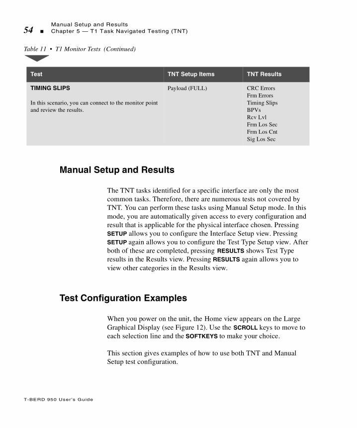
T-BERD 950 User ’s Guide
Manual Setup and Results54 Chapter 5 — T1 Task Navigated Testing (TNT)
Manual Setup and Results
The TNT tasks identified for a specific interface are only the most common tasks. Therefore, there are numerous tests not covered by TNT. You can perform these tasks using Manual Setup mode. In this mode, you are automatically given access to every configuration and result that is applicable for the physical interface chosen. Pressing SETUP allows you to configure the Interface Setup view. Pressing SETUP again allows you to configure the Test Type Setup view. After both of these are completed, pressing RESULTS shows Test Type results in the Results view. Pressing RESULTS again allows you to view other categories in the Results view.
Test Configuration Examples
When you power on the unit, the Home view appears on the Large Graphical Display (see Figure 12). Use the SCROLL keys to move to each selection line and the SOFTKEYS to make your choice.
This section gives examples of how to use both TNT and Manual Setup test configuration.
TIMING SLIPS
In this scenario, you can connect to the monitor point and review the results.
Payload (FULL) CRC ErrorsFrm ErrorsTiming SlipsBPVsRcv LvlFrm Los SecFrm Los CntSig Los Sec
Table 11 • T1 Monitor Tests (Continued)
Test TNT Setup Items TNT Results

T-BERD 950 User ’s Guide
Test Configuration ExamplesChapter 5 — T1 Task Navigated Testing (TNT) 55
TNT Example
In this scenario, your customer has ordered T1 service, and you will need to perform the final acceptance turnup procedures. After you install the smart jack (NIU) at the customer premises, you must run a straightaway (end-to-end) BER test with a CO technician to verify service. This common test scenario requires two testers.
Because this is a common test application, you can use the TNT mode.
1. From the Home view, select T1 as the interface.
Figure 12 • Home View
2. Select T1 BERT TURN-UP as the task.
3. Select STRAIGHTAWAY as the test.
4. Press SETUP to access the TNT Setup view.
Pressing the MORE key shows additional choices. One of those choices is MANUAL SETUP. Manual Setup allows you to set up your test using the Interface and Test Type views. See “Setting Up Manual T1 Test” on page 62 for Manual Setup instructions.
Title Bar
SelectionArea
Interface: T1Task: T1 BERT TURN-UPTest: STRAIGHTAWAY
Prompting
Softkeys
1:1 Home
FUNC
MORE
Select Task To BePerformed:
FT1 BERTTURN-UP
T1/FT1 FRTURN-UP
DDS BERTTURN-UP
T1 BERTTURN-UP
Area
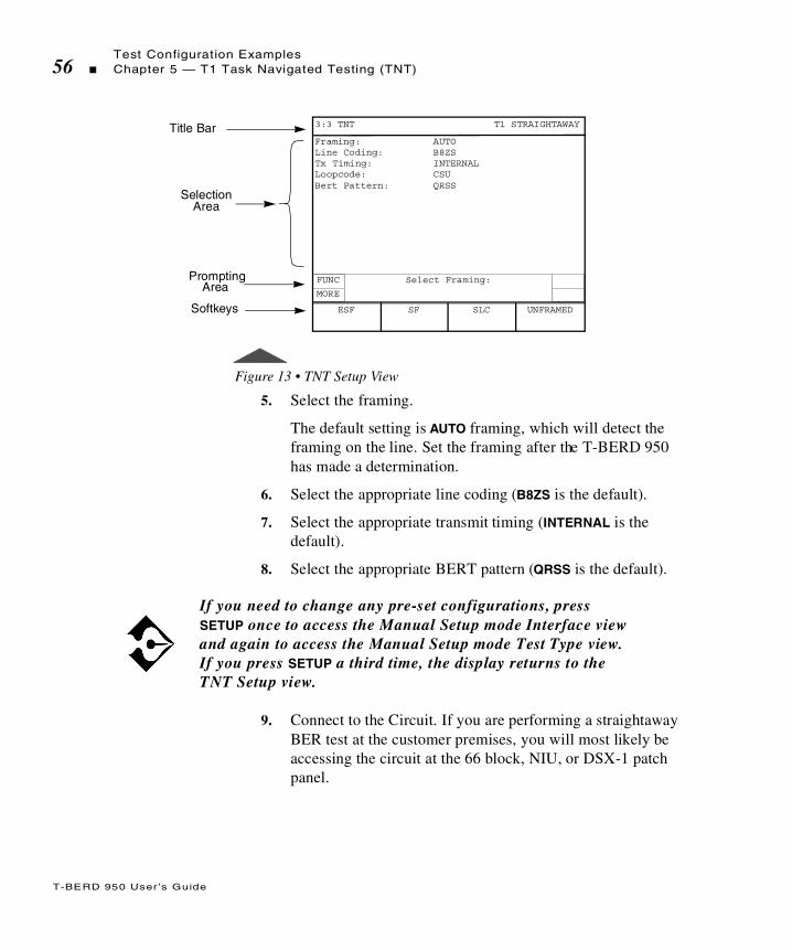
T-BERD 950 User ’s Guide
Test Configuration Examples56 Chapter 5 — T1 Task Navigated Testing (TNT)
Figure 13 • TNT Setup View
5. Select the framing.
The default setting is AUTO framing, which will detect the framing on the line. Set the framing after the T-BERD 950 has made a determination.
6. Select the appropriate line coding (B8ZS is the default).
7. Select the appropriate transmit timing (INTERNAL is the default).
8. Select the appropriate BERT pattern (QRSS is the default).
9. Connect to the Circuit. If you are performing a straightaway BER test at the customer premises, you will most likely be accessing the circuit at the 66 block, NIU, or DSX-1 patch panel.
If you need to change any pre-set configurations, press SETUP once to access the Manual Setup mode Interface view and again to access the Manual Setup mode Test Type view. If you press SETUP a third time, the display returns to the TNT Setup view.
Title Bar
SelectionArea
Framing: AUTOLine Coding: B8ZSTx Timing: INTERNALLoopcode: CSUBert Pattern: QRSS
Prompting
Softkeys
3:3 TNT T1 STRAIGHTAWAY
FUNC
MORE
Select Framing:
SF SLC UNFRAMEDESF
Area
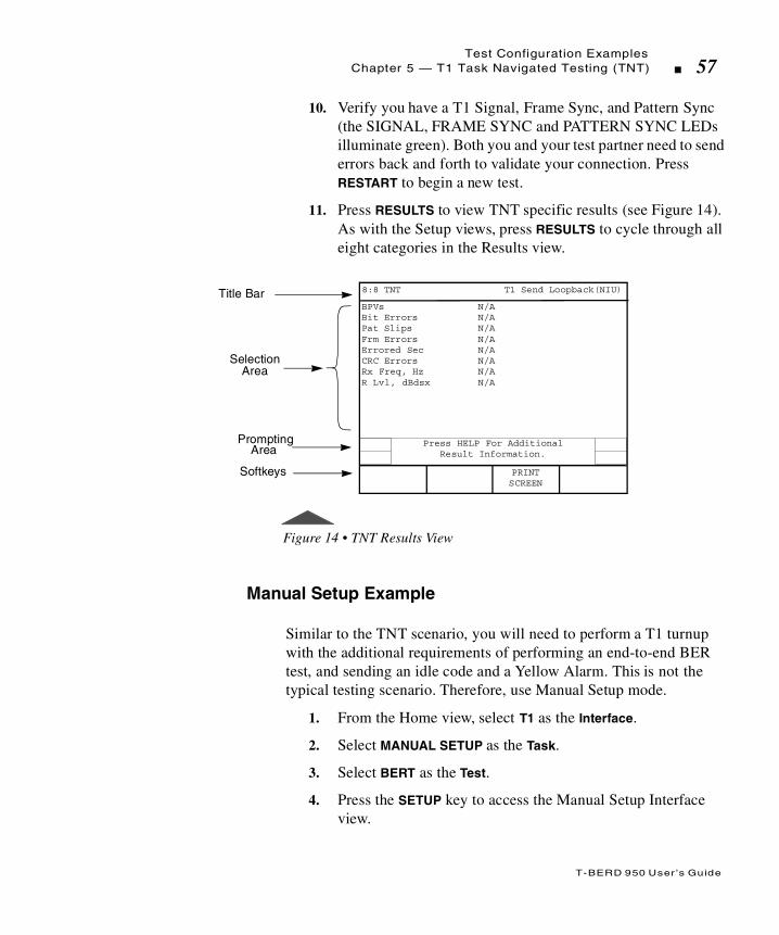
T-BERD 950 User ’s Guide
Test Configuration ExamplesChapter 5 — T1 Task Navigated Testing (TNT) 57
10. Verify you have a T1 Signal, Frame Sync, and Pattern Sync (the SIGNAL, FRAME SYNC and PATTERN SYNC LEDs illuminate green). Both you and your test partner need to send errors back and forth to validate your connection. Press RESTART to begin a new test.
11. Press RESULTS to view TNT specific results (see Figure 14). As with the Setup views, press RESULTS to cycle through all eight categories in the Results view.
Figure 14 • TNT Results View
Manual Setup Example
Similar to the TNT scenario, you will need to perform a T1 turnup with the additional requirements of performing an end-to-end BER test, and sending an idle code and a Yellow Alarm. This is not the typical testing scenario. Therefore, use Manual Setup mode.
1. From the Home view, select T1 as the Interface.
2. Select MANUAL SETUP as the Task.
3. Select BERT as the Test.
4. Press the SETUP key to access the Manual Setup Interface view.
Title Bar
SelectionArea
BPVs N/ABit Errors N/APat Slips N/AFrm Errors N/AErrored Sec N/ACRC Errors N/ARx Freq, Hz N/AR Lvl, dBdsx N/A
Prompting
Softkeys
8:8 TNT T1 Send Loopback(NIU)
Press HELP For AdditionalResult Information.
PRINTSCREEN
Area

T-BERD 950 User ’s Guide
Test Configuration Examples58 Chapter 5 — T1 Task Navigated Testing (TNT)
5. Select TERMINATE as the Mode.
6. Select the appropriate Framing (default is ESF).
7. Select FULL as the Payload.
8. Select the appropriate Line Coding (default is B8ZS).
9. Select TERM as the Line Rx In.
10. Select TERM as the Equip Rx In.
11. Select LINE as the Tx/Rx Pair.
12. Select the appropriate Tx Timing (default is RECOVERED). In this testing scenario, set one test set to RECOVERED and the other to INTERNAL.
A loopcode selection is not required because this is an end-to-end test and you are not looping components.
13. Set Auto-Respond to OFF.
14. Select the appropriate Line LBO if required.
15. Use the keypad to enter the Idle Byte value (default is 11111111).
16. Select ON as the Yellow Alarm to transmit a yellow alarm.
17. Select DS1 Idle Tx to ON to transmit a DS1 idle code.
18. Press SETUP again to access the Manual Setup Test Type view.
19. Select the appropriate Bert Pattern.
20. Select the appropriate Error Insert Type (default is LOGIC).
21. Select the appropriate Error Insert Rate.
22. Connect to the Circuit. If you are performing a straightaway BER test at the customer premises, you will most likely be accessing the circuit at the 66 block, NIU, or DSX-1 patch panel.

T-BERD 950 User ’s Guide
Using the Manual to Setup ConfigurationsChapter 5 — T1 Task Navigated Testing (TNT) 59
Verify you have a T1 Signal, Frame Sync and Pattern Sync (the SIGNAL, FRAME SYNC and PATTERN SYNC LEDs illuminate green), and exchange errors with your test partner to validate your connection.
23. Press RESTART to begin a new test.
24. Press RESULTS to show the Results Test Type Category view.
25. Press RESULTS to cycle through the all seven result category views, and check the results for which you are concerned (i.e., BPVs, bit errors, CRC errors, simplex current, and signal level).
Using the Manual to Setup Configurations
The remaining chapters are organized by interface and option. Each chapter provides both TNT and Manual Setup information. Unless it is related to a specific option (i.e., Frame Relay), the configuration is described in the appropriate interface section. For example, even though you can test the frame relay option with the T1 or DDS-LL interface, it is only available if you have the option (regardless of the interface). Therefore, all frame relay TNT scenarios are described in the Frame Relay Option section. This same principle applies to the Primary Rate ISDN Option as well.
In each option/interface chapter, the TNT tasks are described and the tests within each task are presented in a table. This table explains the specific test as is pertains to the associated task. Also provided in these tables are the configurable parameters in the TNT Setup view and the results in the TNT Results view. The TNT Setup parameter defaults are listed in parentheses () beside the TNT Setup parameter.
Following the TNT descriptions are the Manual Setup parameter descriptions for the Interface and Test Type views, in addition to detailed results information by category. Because the setup parameters and results for TNT are a subset of those for Manual Setup, refer to the Manual Setup section for definitions of these items.

T-BERD 950 User ’s Guide
Using the Manual to Setup Configurations60 Chapter 5 — T1 Task Navigated Testing (TNT)

T
T-BERD 950 User ’s Guide
his section describes the basic test setup for the T1 interface on the T-BERD 950.
Chap te r6 T1 Manual Test
Setup

T-BERD 950 User ’s Guide
Setting Up Manual T1 Test62 Chapter 6 — T1 Manual Test Setup
Setting Up Manual T1 Test
This section provides descriptions of the test setup parameters to perform a variety of tests using the manual setups for the T1 interface.
Setting Up the Home View
Start with the Home view as shown in Figure 15.
1. Select the T1 Interface.
2. Select the MANUAL SETUP Task.
3. Select the BERT Test.
4. Press the SETUP key.
Figure 15 • Home View
Setting Up the T1 Interface View
The Setup Interface view is used to configure the T1 interface (see Figure 16). Use the SCROLL and PAGE keys to control this selection area.
Title Bar
SelectionArea
Interface: T1Task: MANUAL SETUPTest Type: BERT
Prompting
Softkeys
1:3 Home T1-BERT
FUNC Select Mode:
AUTO AUTO-RDELAY
Area
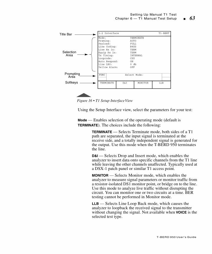
T-BERD 950 User ’s Guide
Setting Up Manual T1 TestChapter 6 — T1 Manual Test Setup 63
Figure 16 • T1 Setup Interface View
Using the Setup Interface view, select the parameters for your test:
Mode — Enables selection of the operating mode (default is TERMINATE). The choices include the following:
TERMINATE — Selects Terminate mode, both sides of a T1 path are separated, the input signal is terminated at the receive side, and a totally independent signal is generated for the output. Use this mode when the T-BERD 950 terminates the line.
D&I — Selects Drop and Insert mode, which enables the analyzer to insert data onto specific channels from the T1 line while leaving the other channels unaffected. Typically used at a DSX-1 patch panel or similar T1 access point.
MONITOR — Selects Monitor mode, which enables the analyzer to measure signal parameters or monitor traffic from a resistor-isolated DS1 monitor point, or bridge on to the line. Use this mode to analyze live traffic without disrupting the circuit. You can monitor one or two circuits at a time. BER testing cannot be performed in Monitor mode.
LLB — Selects Line Loop Back mode, which causes the analyzer to loopback the received signal to the transmitter without changing the signal. Not available when VOICE is the selected test type.
Title Bar
SelectionArea
Mode: TERMINATEFraming: AUTOPayload: FULLLine Coding: B8ZSLine Rx In: TERMEquip Rx In: TERMTx Timing: INTERNALLoopcode: CSUAuto Respond: ONLine LBO: 0 dbYellow Alarm: OFF
Prompting
Softkeys
1:2 Interface T1-BERT
FUNC Select Mode:
D&I MONITOR LLBTERMINATE
Area

T-BERD 950 User ’s Guide
Setting Up Manual T1 Test64 Chapter 6 — T1 Manual Test Setup
Framing — (all operating modes) Selects the framing format for the T1 signal (default is ESF). Choices include:
ESF — Enables transmission and analysis of T1 signals with Extended SuperFrame (ESF) framing format.
SF — Enables transmission and analysis of T1 signals with SuperFrame (SF) framing format.
SLC — Enables transmission and analysis of T1 signals with SLC-96 framing.
UNFRAMED — Enables data analysis on the full 1.544 Mbps bandwidth of the T1 line. No framing bits are added during transmission, and no data bits are stripped when received. Not available in D&I mode or when VOICE is the selected test type.
AUTO — Performs automatic Frame Search. The unit automatically configures the receivers and transmitters to the incoming framed and unframed T1 signals. AUTO Framing Searching appears on the RESULTS I and II display while the unit attempts to identify the received framing mode. If frame synchronization is received, the detected mode will be printed in lowercase letters on the Setup view, as indicated in Table 12.
Not all of the following selection lines are available in all operating modes.
Table 12 • AUTO Framing
T1 Signal Format AUTO Mode Selection
D1D *sf
D2 *sf
D4 *sf

T-BERD 950 User ’s Guide
Setting Up Manual T1 TestChapter 6 — T1 Manual Test Setup 65
AUTO-R — Performs Automatic Restart Frame Search. The unit operates in the manner described in AUTO; however, it automatically searches for frame synchronization upon the loss of frame synchronization or when signal is lost and reacquired (i.e., when the Frame Sync LED is no longer illuminated).
Payload — (not available for VOICE testing) Enables selection of the circuit type to be tested (default is FULL). Choices include:
FULL — (not available in D&I operating mode) Configures the analyzer to transmit and receive data at the full T1 rate.
ESF *esf
SLC *slc
Unframed unframed
AUTO mode is performed concurrently on the LINE and EQUIPMENT receivers. The T-BERD 950 tries to synchronize to the LINE input. If framing synchronization is achieved, the green LINE Frame Sync LED illuminates; the detected mode appears in lowercase letters; and the T-BERD 950 tries to synchronize to the same frame format with EQUIPMENT. If EQUIPMENT frame format is not the same as LINE, then the green EQUIPMENT Frame Sync does not illuminate. Neither the LINE nor the EQUIPMENT frame sync LEDs will be illuminated in this scenario.
Auto-R this mode should not be selected when performing long-term, unattended testing, because valid testing results will be cleared each time frame sync is reacquired.
Table 12 • AUTO Framing (Continued)
T1 Signal Format AUTO Mode Selection

T-BERD 950 User ’s Guide
Setting Up Manual T1 Test66 Chapter 6 — T1 Manual Test Setup
Nx56 — Selects the channel bandwidth for Nx56 kbps data analysis. This selection line shows only the number of channels currently selected. Selecting Nx56 accesses the Channels selection line.
Nx64 — Selects the channel bandwidth for Nx64 kbps data analysis. This selection line shows only the number of channels currently selected. Selecting Nx64 accesses the Channels selection line.
Channels — (Nx54 and Nx64) Selects the channel to test. Use the softkeys to select the channel.
DDS — Selects DDS over T1 analysis and enables the selection of an individual T1 (DS0) channel to be tested.
Channel — Selects a specific DS0 channel to be tested. Use the INCREASE VALUE or DECREASE VALUE softkeys to set the channel.
Rate — Selects the unframed channel format and data transmission subrate over the DS0 64 kbps channel (default is CLEAR CHANNEL). Choices include:
CLEAR CHANNEL — Select to test DS0-A formatted DDS data at 64 kbps. Uses entire DS0 bandwidth.
DS0A56 — Select to test DS0-A formatted DDS data at 56 kbps. Uses the entire DS0 bandwidth, except bit 8, which is controlled by the analyzer and distinguishes customer data from network control information.
DS0A9.6 — Select to test DS0A formatted DDS data at 9.6 kbps. Copies all eight bits of the DS0A9.6 bandwidth five times into the selected 64 kbps channel.
DS0A4.8 — Select to test DS0A formatted DDS data at 4.8 kbps. Copies all eight bits of the DS04.8 bandwidth 10 times into the selected 64 kbps channel.
DS0A2.4 — Select to test DS0A formatted DDS data at 2.4 kbps. Copies all eight bits of the DS02.4 bandwidth 20 times into the selected 64 kbps channel.
T-BERD 950 User ’s Guide
Setting Up Manual T1 TestChapter 6 — T1 Manual Test Setup 67
Line Coding — (all operating modes) Enables selection of the line coding for the transmitted data (default is B8ZS). Choices include:
AMI — Selects Alternate Mark Inversion (AMI) coding.
B8ZS — Selects Bipolar with 8 Zero Substitution (B8ZS) coding.
Line Rx In — (all operating modes) Enables selection of the LINE receiver input impedance and signal conditioning (default is TERM). Choices include:
TERM — Select when the T-BERD 950 terminates the line. Provides 100 Ω ± 5% resistive termination.
DSX MON — Select when the T-BERD 950 connects to the circuit via the DSX-1 patch panel or similar access point. Provides resistive compensation for signals with +6.0 dBdsx to -35 dBdsx of cable loss at 772 kHz, and can accommodate signals resistively attenuated from +0.0 dBdsx through -26.0 dBdsx.
BRIDGE — Select when the T-BERD 950 bridges onto the circuit. Provides greater than 1000 Ω resistive termination.
Equip Rx In — (all operating modes) Enables selection of the EQUIPMENT receiver input impedance and signal conditioning (default is DSX-MON). Choices include:
TERM — Select when the T-BERD 950 terminates the line. Provides 100Ω ±5% resistive termination.
DSX MON — Select when the T-BERD 950 connects to the circuit via the DSX-1 patch panel or similar access point. Provides resistive compensation for signals with +6.0 dBdsx to -35 dBdsx of cable loss at 772 kHz, and can accommodate signals resistively attenuated from +0.0 dBdsx through -26.0 dBdsx.
BRIDGE — Select when the T-BERD 950 bridges onto the circuit. Provides greater than 1000 Ω resistive termination.
Insert Side — (D&I operating mode only) Enables selection of the T1 interface that data is inserted on (default is LINE Tx). Choices include:
LINE Tx or EQUIPMENT Tx— Selects the T1 LINE or EQUIPMENT transmitter.

T-BERD 950 User ’s Guide
Setting Up Manual T1 Test68 Chapter 6 — T1 Manual Test Setup
Insert Payload — (D&I operating mode only) Turns payload insertion on or off (default is OFF).
Tx/Rx Pair — (TERMINATE operating mode only) Enables selection of the receiver and transmitter pair (default is LINE). Choices include:
LINE or EQUIPMENT— Selects the LINE or EQUIPMENT receiver and transmitter pair.
Tx Timing — (TERMINATE operating mode only) Enables selection of the signal timing source for each of the T1 transmit channels, LINE and EQUIPMENT (default is RECOVERED). Choices include:
RECOVERED — Selects the receiver channel clock as the timing source for the transmitter. Timing is derived from the incoming (Rx) signal.
INTERNAL — Selects the internal crystal oscillator as the timing source for the transmitter.
Setting DDS Loop Codes
Loop Code Type — (DDS payload only) Enables the selection of either latching or alternating loop codes (default is LATCHING). Choices include:
LATCHING — Enables selection of a latching loop code where all eight bits of a DS0 are used to transmit network control codes. The success or failure of latching loop code operation will be reported at the end of each latching loop up or loop down operation on the Two-Line Display.
ALTERNATING — Enables selection of an alternating (non-latching) loop code where the payload data is intermixed every other byte with the loop code. The success or failure of an alternating loop code operation shall be reported at the end of each loop up or loop down.
Whenever any of the following parameters are changed, Insert Payload is reset to OFF: Mode, Framing, Line Coding, Line Rx In, Equip Rx In, Payload, Insert Side, Line LBO, Equip LBO, Channels, Tx Timing, and Test Type. In addition, each time D&I mode is selected, Insert Payload is reset to OFF.

T-BERD 950 User ’s Guide
Setting Up Manual T1 TestChapter 6 — T1 Manual Test Setup 69
Loop Code — (TERMINATE operating mode only) Enables selection of the loop code sequence transmitted through the active channels or through the ESF Data Link when the LOOP UP and LOOP DOWN keys are pressed (default is CSU). Choices for DDS include:
CSU — (DDS ALTERNATING or LATCHING loop code type only) Selects the loop code for a Channel Service Unit. Alternating loop code: S0101000. Latching loop code: N0110001.
CSU+R — (ALTERNATING loop code type only) Selects the alternating loop code for a Channel Service Unit with one repeater between the CSU and the analyzer. Alternating loop code: S0101000.
When a repeater is on the span, the CSU+R loops up the repeater with the CSU loop up sequence. The analyzer loops down the repeater, allowing the following transmission to pass through. The CSU then loops up with the standard alternating loop back activation.
CSU+2R — (ALTERNATING loop code type only) Selects alternating loop code for a Channel Service Unit with two repeaters between the CSU and the analyzer. Alternating loop code: S0101000.
When two repeaters are on the span, the sequence for the (CSU+2R) loop code is the same as the CSU+R, except, after the second loop up sequence is transmitted, a second loop down sequence is transmitted, followed by a third loopback activation sequence.
1ST RPTR — (ALTERNATING loop code type only) Selects First 56 kbps repeater. Alternating loop code: S0101000.
2ND RPTR — (ALTERNATING loop code type only) Selects Second 56 kbps repeater. Alternating loop code: S0101000.
An “n” signifies a “don’t care” value an “S” signifies the subrate framing bit; “1” when transmitting/receiving an idle code of a 56 kbps DS0A signal; “0” when transmitting/receiving a DSU loopback of a 56 kbps DS0A signal; or “don’t care” for all other transmitted/received DS0A signals.
T-BERD 950 User ’s Guide
Setting Up Manual T1 Test70 Chapter 6 — T1 Manual Test Setup
OCU — (ALTERNATING or LATCHING loop code type only) Selects Office Channel Unit loop code. Alternating loop code: S0101010. Latching loop code: N1010101.
The OCU+HL96 code loops up with the OCU sequence. The analyzer loops down the HL96NY, allowing the following transmissions to pass through. The OCU is then looped up with the standard alternating loopback activation sequence.
OCU+HL96 — (ALTERNATING loop code type only) Selects Office Channel Unit behind a HL96NY. Alternating loop code: S0101010.
HL96NY — (ALTERNATING loop code type only) Selects HL96NY Office Channel Unit. Alternating loop code: S0101010.
LSI — (LATCHING loop code type only) Selects LIN Side Interface. Latching loop code: N1000111.
NEI — (LATCHING loop code type only) Selects Network Element Interface. Latching loop code: N1000001.
The DS0-DP loop code loops up or down any DS0 data port within a series of eight DS0 data ports. At the completion of the loop, feedback is read from the looped DS0 data port that determines if the DS0 data port is configured from the LINE side or drop side.
DS0-DP — (LATCHING loop code type only) Selects DS0-Data Port latching loop code: N0000101.
Location — Selects the data port location. Choices include: 1, 2, 3, 4, 5, 6, 7, or 8.
DSU — (ALTERNATING or LATCHING loop code type only) Selects Data Service Unit loop code. Alternating loop code: S0101100. Latching loop code: N1110111.
Setting T1 Loop Codes
Loop Code — (TERMINATE operating mode only) Enables selection of the loop code sequence transmitted through the active channels or through the ESF Data Link when the LOOP UP and LOOP DOWN keys are pressed (default is CSU). Choices include:

T-BERD 950 User ’s Guide
Setting Up Manual T1 TestChapter 6 — T1 Manual Test Setup 71
CSU — (not available for DDS) Selects repeating inband Channel Service Unit (CSU) loop codes: loop up = 10000 and loop down = 100. These loop codes are valid in Full T1, Fractional T1, and all framing modes.
NIU — (not available for DDS) Enables selection of network interface (or smart jack) inband repeating codes.
NIU Type — Selection line appears, allowing selection of the Facility Type codes listed below.
FAC1 — Selects Facility Type 1 network interface (or smart jack) inband repeating 4-bit loop codes: loop up = 1100 and loop down = 1110. These loop codes are valid in Full T1, Fractional T1, and all framing modes.
FAC2 — Selects Facility Type 2 network interface (or smart jack) inband repeating 5-bit loop codes: loop up = 11000 and loop down = 11100. These loop codes are valid in Full T1, Fractional T1, and all framing modes.
FAC3 — Selects Facility Type 3 network interface (or smart jack) inband repeating 6-bit loop codes: loop up = 100000 and loop down = 100. These loop codes are valid in Full T1, Fractional T1, and all framing modes.
REPEATER — (FULL payload only) Selects repeater loop codes sent over the T1 interface.
Repeater Type — Selects Repeater type (see Table 13).
Table 13 • Repeater Typ e
Central Office Repeaters Line Repeaters
Teltrend 7231LP/LW IOR Teltrend 7239LP/LW ILR
Teltrend 9132LP/LW IHR WSTL 315056 ILR A/B
WSTL 313056 IOR A/B WSTL 315056 ILR C..
WSTL 313056 IOR C.. WSTL 315156 ILR
WSTL 313080 IOR WSTL 313080 ILR
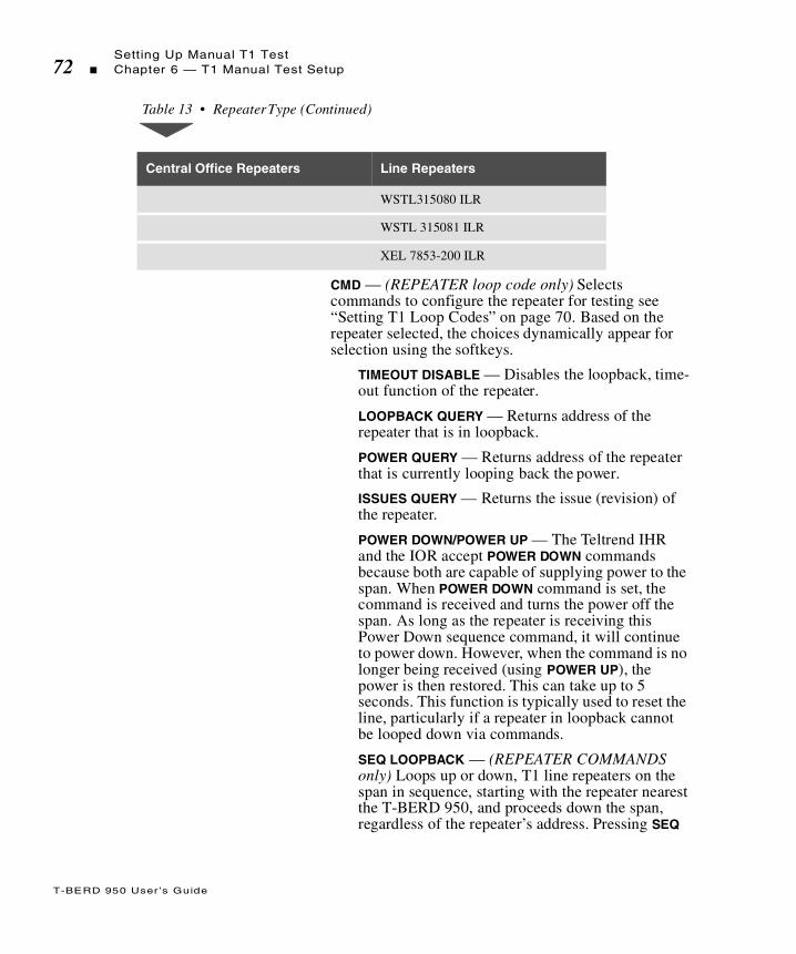
T-BERD 950 User ’s Guide
Setting Up Manual T1 Test72 Chapter 6 — T1 Manual Test Setup
CMD — (REPEATER loop code only) Selects commands to configure the repeater for testing see “Setting T1 Loop Codes” on page 70. Based on the repeater selected, the choices dynamically appear for selection using the softkeys.
TIMEOUT DISABLE — Disables the loopback, time-out function of the repeater.
LOOPBACK QUERY — Returns address of the repeater that is in loopback.
POWER QUERY — Returns address of the repeater that is currently looping back the power.
ISSUES QUERY — Returns the issue (revision) of the repeater.
POWER DOWN/POWER UP — The Teltrend IHR and the IOR accept POWER DOWN commands because both are capable of supplying power to the span. When POWER DOWN command is set, the command is received and turns the power off the span. As long as the repeater is receiving this Power Down sequence command, it will continue to power down. However, when the command is no longer being received (using POWER UP), the power is then restored. This can take up to 5 seconds. This function is typically used to reset the line, particularly if a repeater in loopback cannot be looped down via commands.
SEQ LOOPBACK — (REPEATER COMMANDS only) Loops up or down, T1 line repeaters on the span in sequence, starting with the repeater nearest the T-BERD 950, and proceeds down the span, regardless of the repeater’s address. Pressing SEQ
WSTL315080 ILR
WSTL 315081 ILR
XEL 7853-200 ILR
Table 13 • Repeater Type (Continued)
Central Office Repeaters Line Repeaters

T-BERD 950 User ’s Guide
Setting Up Manual T1 TestChapter 6 — T1 Manual Test Setup 73
LOOPBACK transmits the sequential loopback code. The first repeater on the span will loop up, return its address, then loop down. This loopback procedure continues for each repeater on the span.
Table 14 lists the command sets and addresses for the repeater type.
Table 15 shows the commands available for each command set.
Table 14 • Commands and Addresses for Repeater s
Command Set
Address Repeater Type
1 — Teltrend 7231LP/LW IOR
— Teltrend 9132LP/LW IHR
2 up to 20 Teltrend 7239LP/LW ILR
3 up to 1999 Westell 3130-80 IOR
up to 2 Westell 3130-56 IOR
4 up to 1999 Westell 3150-80 ILR
up to 1999 Westell 3150-81 ILR
5 up to 20 Westell 3150-56 ILR
up to 20 Westell 3151-56 ILR
Table 15 • Command Se ts
Command Set 1 Set 2 Set 3 Set 4 Set 5
Timeout Disable
Loopback Query
Power Query
Issues Query

T-BERD 950 User ’s Guide
Setting Up Manual T1 Test74 Chapter 6 — T1 Manual Test Setup
HDSL — (FULL payload only) High bit-rate Digital Subscriber Line. Selects HDSL loop code transmitted over the HDSL circuit.
HDSL Type — Selects HDSL type (see Table 16).
Adtran Codes — (HDSL loop code only) Choices include: STANDARD and ABBREVIATED. Default is ABBREVIATED (no softkeys available). If STANDARD is selected, the REPEATER CMDS softkey becomes available. See “Using HDSL and Repeater Commands Softkeys” on page 75.
PairGain Codes — (HDSL loop code only) Choices include: A2LB and GENERIC. Default is GENERIC (no softkeys available). If A2LB is selected, the REPEATER CMDS softkey becomes available. See “Using HDSL and Repeater Commands Softkeys” on page 75.
Origin of Test — (REPEATER and select HDSL loop codes only) Selects point of origin of the test. Choices include: CENTRAL OFFICE or CUSTOMER PREM. The default is CENTRAL OFFICE.
Power Up
Power Down
Sequential Loopback
Table 16 • HDSL Equipment
HDSL Central Office Cards Repeaters/Doublers Customer Premises Cards
Adtran HTU-C Adtran HRE Adtran HTU-R
PairGain HLU PairGain HDU PairGain HRU
Table 15 • Command Sets (Continued)
Command Set 1 Set 2 Set 3 Set 4 Set 5

T-BERD 950 User ’s Guide
Setting Up Manual T1 TestChapter 6 — T1 Manual Test Setup 75
Address — (HDSL loop codes only) Set the address of the HDSL equipment.
Using HDSL and Repeater Commands Softkeys
To access the REPEATER CMDS softkey, press FUNCTION softkey control. Press the REPEATER CMDS softkey to access to ARM, NEAR END ARM, DISARM, ADDR UP, and ADDR DWN softkeys.
ARM — Transmits an arming code on the span when testing from the Central Office toward the NIU to prepare the span for receipt of loop up or loop down codes.
NEAR END ARM — Transmits a near-end arming code on the span when testing from the NIU toward the Central Office (CO) to prepare the span for receipt of loop up or loop down codes.
DISARM — Transmits a disarming code on the span to disarm the span when testing is completed.
ADDR UP / ADDR DOWN — Increments or decrements (by one) the repeater address from the current address.
PROGRAMMABLE — Selects user-programmable inband loop codes (3 to 16 bit loop up and loop down codes), the left-most bit of each code string is transmitted first. These loop codes are valid in Full T1, Fractional T1, and all framing modes. When selected, the following selection lines are available:
Prog Set # — Allows you to program and access up to 10 user-programmable loop up and loop down codes. Each set contains its own 16 bit loop up code and loop down code. You can label each of the user-programmable codes Loop Up Code (n) and Loop Down Code (n) with alphanumeric characters. See “Editing User-Programmable Fields” on page 77 for details on editing this field.
Loop Up Code (n) — Enables setting the binary value of the loop up code (default is 10000). The left and right arrow keys on the keypad are used to select the individual bit to be set, and the zero (0) or one (1) key on the keypad is used to set the bit value.

T-BERD 950 User ’s Guide
Setting Up Manual T1 Test76 Chapter 6 — T1 Manual Test Setup
Loop Down Code (n) — Enables setting the binary value of the loop down code (default is 100). The left and right arrow keys on the keypad are used to select the individual bit to be set, and the zero (0) or one (1) key on the keypad is used to set the bit value.
V.54 — (not available when DDS loop code type is ALTERNATING) Selects inband loop code transmitted over a Fractional T1 bandwidth.
DATALINK — (ESF framing only) A communications connection used to transmit data. These loop codes comply with the ANSI T1.403 (‘95) specifications Datalink Type.
DL-LLB — Selects out-of-band ESF Data Link Line Loopback codes. The loop codes include: loop up = 1111 1111 0111 0000 and loop down = 1111 1111 0001 1100; the left-most bit of each code string is transmitted first. These loop codes are valid in Full T1 or Fractional T1 when ESF framing is selected.
DL-PLB — Selects out-of-band ESF Data Link Payload Loopback codes. The loop codes include: loop up = 1111 1111 0010 1000 and loop down = 1111 1111 0100 1100; the left-most bit of each code string is transmitted first. These loop codes are valid in Full T1 or Fractional T1 when ESF framing is selected.
DL-NET — Selects out-of-band ESF Data Link Network Loopback codes. The loop codes include: loop up = 0000 0000 0100 1000 and loop down = 0000 0000 0010 0100; the left-most bit of each code string is transmitted first. The loop codes are valid in Full T1 or Fractional T1 when ESF framing is selected.
Auto-Respond — (TERMINATE and D&I operating modes only) Enables Auto-Respond (to loop codes) to be turned ON or OFF (default is OFF). When Auto-Respond is set to ON, the analyzer is configured for automatic loop code response and the response status
In D&I mode, the only loop code responded to is V.54.

T-BERD 950 User ’s Guide
Setting Up Manual T1 TestChapter 6 — T1 Manual Test Setup 77
will appear on the Two-Line Display. The applicability of the loop code and the mode (Fractional T1 or Full T1) determine what is actually looped back (Line, Payload or Fractional Payload).
ON — Turns Auto-Respond to selected loop codes on.
OFF — Turns Auto-Respond to selected loop codes off.
Editing User-Programmable Fields
This feature allows you to enter any combination of alphanumeric characters to label your programmable loop codes for testing.
1. Select the Loop Up Code (n) or Loop Down Code (n) field. The EDIT softkey appears.
2. Press the EDIT softkey and a popup window appears. Additional softkeys appear.
Clear — Clears the field.
Home — Places the cursor at the beginning of the string.
End — Places the cursor at the end of the string.
3. Press the 1 through 9, or 0 key on keypad to select a character set. The assigned values for that key are shown in the popup window.
4. Press the corresponding number for the character you want to place into the user data information. Press 0 to add spaces if needed.
5. Repeat steps 3 and 4 until your loop code label is complete.
6. Press SCROLL when finished to move to the next selection line.
Line LBO — (TERMINATE [with Tx/Rx Pair=LINE] and D&I operating modes only) Enables emulation of four different cable losses for the T1 LINE output signal level (default is 0 dB). The selected cable loss affects the transmit data only at the connectors. Choices include:

T-BERD 950 User ’s Guide
Setting Up Manual T1 Test78 Chapter 6 — T1 Manual Test Setup
0 dB — Sets the output (Tx) to the DSX level with no line build-out (0 dB attenuation).
-7.5 dB — Provides -7.5 dB line build-out, attenuating the output with 7.5 dB of simulated cable loss.
-15 dB — Provides -15 dB line build-out, attenuating the output with 15 dB of simulated cable loss.
-22.5 dB — Provides -22.5 dB line build-out, attenuating the output with 22.5 dB of simulated cable loss.
Equip LBO — (TERMINATE [with Tx/Rx Pair=EQUIP] and D&I operating modes only) Enables emulation of four different cable losses for the T1 EQUIPMENT output signal level (default is 0 dB). The selected cable loss affects the transmit data only at the connectors. Choices include:
0 dB — Sets the output (Tx) to the DSX level with no line build-out (0 dB attenuation).
-7.5 dB — Provides -7.5 dB line build-out, attenuating the output with 7.5 dB of simulated cable loss.
-15 dB — Provides -15 dB line build-out, attenuating the output with 15 dB of simulated cable loss.
-22.5 dB — Provides -22.5 dB line build-out, attenuating the output with 22.5 dB of simulated cable loss.
Idle Byte — (TERMINATE and D&I operating modes only) Enables setting the binary value of the idle byte to be inserted on inactive channels (default is 11111111). The left and right arrow keys on the keypad are used to select the individual bit to be set, and the zero (0) or one (1) key on the keypad is used to set the bit value. The idle byte is inserted in the opposite direction of the inserted payload in D&I mode to block looped test patterns.
Yellow Alarm — (TERMINATE and D&I operating modes only) Enables selection of yellow alarm (default is OFF). Choices include:
Auto — Automatically transmits yellow alarm upon Loss of Signal.
ON — Turns on transmission of yellow alarm.
OFF — Turns off transmission of yellow alarm.
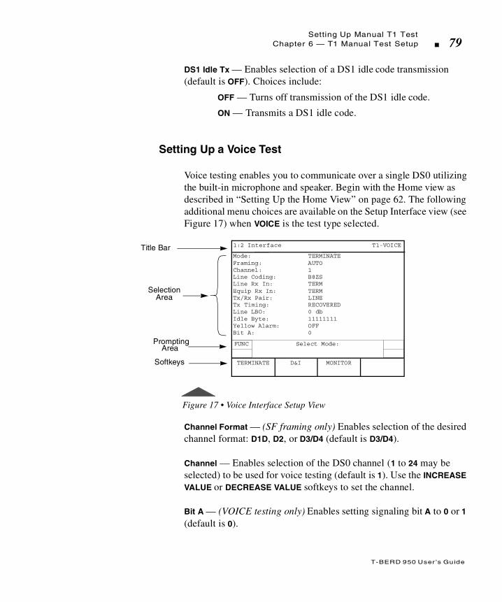
T-BERD 950 User ’s Guide
Setting Up Manual T1 TestChapter 6 — T1 Manual Test Setup 79
DS1 Idle Tx — Enables selection of a DS1 idle code transmission (default is OFF). Choices include:
OFF — Turns off transmission of the DS1 idle code.
ON — Transmits a DS1 idle code.
Setting Up a Voice Test
Voice testing enables you to communicate over a single DS0 utilizing the built-in microphone and speaker. Begin with the Home view as described in “Setting Up the Home View” on page 62. The following additional menu choices are available on the Setup Interface view (see Figure 17) when VOICE is the test type selected.
Figure 17 • Voice Interface Setup View
Channel Format — (SF framing only) Enables selection of the desired channel format: D1D, D2, or D3/D4 (default is D3/D4).
Channel — Enables selection of the DS0 channel (1 to 24 may be selected) to be used for voice testing (default is 1). Use the INCREASE VALUE or DECREASE VALUE softkeys to set the channel.
Bit A — (VOICE testing only) Enables setting signaling bit A to 0 or 1 (default is 0).
Title Bar
SelectionArea
Mode: TERMINATEFraming: AUTOChannel: 1Line Coding: B8ZSLine Rx In: TERMEquip Rx In: TERMTx/Rx Pair: LINETx Timing: RECOVEREDLine LBO: 0 dbIdle Byte: 11111111Yellow Alarm: OFFBit A: 0
Prompting
Softkeys
1:2 Interface T1-VOICE
FUNC Select Mode:
D&I MONITORTERMINATE
Area

T-BERD 950 User ’s Guide
Setting Up Manual T1 Test80 Chapter 6 — T1 Manual Test Setup
Bit B — (VOICE testing only) Enables setting signaling bit B to 0 or 1 (default is 1).
Bit C — (VOICE testing only — ESF framing only) Enables setting signaling bit C to 0 or 1 (default is 1).
Bit D — (VOICE testing only — ESF framing only) Enables setting signaling bit D to 0 or 1 (default is 1).
Setting Up the T1 Test Type View
The T1 Test Type view is used to configure the BER Test to be performed. The SCROLL and PAGE keys are used to control this selection area.
Press the SETUP view key for the Test Type view.
Figure 18 • T1 Test Type View
Title Bar
SelectionArea
Bert Pattern: AUTOError Insert Type: LOGICError Rate: 1x10⁻³
Prompting
Softkeys
1:2 Test Type T1-BERT
FUNC
MORE
Select Mode:
AUTO AUTO-RDELAY
Area

T-BERD 950 User ’s Guide
Setting Up Manual T1 TestChapter 6 — T1 Manual Test Setup 81
T1 BERT Patterns
Bert Pattern — (TERMINATE, D&I, and MONITOR only) Enables the selection of the required test pattern (default is 2047). Unless otherwise stated, all patterns are transmitted from left to right and are available for use in full T1 and fractional T1 testing. Choices include:
All Ones — Selects a fixed pattern of AMI pulses. Used to stress repeaters or as a keep alive idle (AIS) code in a T1 signal. In DDS its an idle or keep alive signal.
All Zeros — (FULL T1 only) Selects the B8ZS Clear Channel Compatibility Test Pattern. Helps isolate mis-optioned AMI equipment.
1:7 — (FULL T1 only) Selects a fixed pattern — F01000000... where F is the frame bit. Tests the minimal ones density for AMI circuits.
2 in 8 — (FULL T1 only) Selects a fixed pattern — F01000010... where F is the frame bit. Used to stress B8ZS circuits.
3 in 24 — (FULL T1 only) Selects a fixed pattern — F010001000000000000000100... where F is the frame bit. Stresses maximum zeroes and minimum ones density at the same time.
QRSS — Selects the 220-1 Pseudorandom pattern with a maximum of 15 sequential 0s and 20 sequential 1s. Simulates live T1 traffic.
2^23-1 — Selects the 223-1 Pseudorandom pattern, which generates a maximum of 22 sequential 0s and 23 sequential 1s. Simulates live data for DS3 and SONET circuits.
2^20-1 — Selects the 220-1 Pseudorandom pattern, which generates a maximum of 19 sequential 0s and 20 sequential 1s. Simulates live data for DS2 circuits.
2^15-1 — Selects the 215-1 Pseudorandom pattern, which generates a maximum of 14 sequential 0s and 15 sequential 1s. Simulates live data for 56 kbps to 2Mbps circuits.
2^15-1 INV — Selects the inverted 215-1 Pseudorandom pattern, which generates a maximum of 15 sequential 0s and 14 sequential 1s. Provides the maximum number of zeroes allowed for framed, non-B8ZS testing.

T-BERD 950 User ’s Guide
Setting Up Manual T1 Test82 Chapter 6 — T1 Manual Test Setup
2047 — Selects the 211-1 Pseudorandom pattern, which generates a maximum of 10 sequential 0s and 11 sequential 1s. Simulates live data for circuits 56 kbps and lower. (Used for DDS and ISDN.)
T1-1 (MIN/MAX) — (FULL T1 only) Selects a fixed pattern that generates rapid changes in ones density. Tests the repeaters ability to readjust to rapid changes in ones density.
T1-2/96 — (FULL T1 only) Selects the 96 octet fixed stress pattern (transmitted right to left). Stresses repeater preamplifier and Automatic Line Build Out (ALBO) circuitry. Detects marginal equipment using rapid transitions between low and high ones density.
T1-3/54 — (FULL T1 only) Selects the 54 octet fixed stress pattern (transmitted right to left). Stresses circuits and equipment.
T1-4/120 — (FULL T1 only) Selects the 120 octet fixed stress pattern (transmitted right to left). Stresses circuits and equipment. Should not be used on ESF circuits because it contains false ESF framing bits.
T1-5/53 — (FULL T1 only) Selects the 53 octet fixed stress pattern (transmitted right to left). Stresses circuits and equipment.
T1-6/55 — (FULL T1 only) Selects an unframed 55 octet fixed stress pattern (transmitted right to left). Tests the ability of the repeater to lock onto the incoming clock when data changes between high and low ones density.
T1 DALY — (FULL T1 only) Selects a framed 55 octet fixed stress pattern (transmitted right to left). This is the same as T1-6/55, except that byte 7 is 80 instead of 00. Use with framed T1 circuits without causing excess zeroes.
BRIDGETAP — (FULL T1 only) Selects an automated test that transmits 21 consecutive test patterns: ALL ONES, 1:1, 1:3, 1:5, 1:6, 1:7, 2:8, 2:9, 2:10, 2:11, 2:12, 2:13, 2:14, 3 in 18, 3 in 19, 3 in 20, 3 in 21, 3 in 22, 3 in 23, 3 in 24, and QRSS. Bridgetaps are faults that, depending on the location and length of the bridgetap, affect different frequencies in the T1 spectrum. Typically, a bridgetap is identified if more than one consecutive pattern fails. Multiple series of failures can indicate more than one bridgetap.

T-BERD 950 User ’s Guide
Setting Up Manual T1 TestChapter 6 — T1 Manual Test Setup 83
MULTIPAT — (FULL T1 only) Selects an automated test that transmits 5 consecutive test patterns: ALL ONES, 1:7, 2:8, 3 in 24, and QRSS. Use the keypad to change the time for each pattern.
MULTIPAT 2 — (FULL T1 only) Selects an automated test that transmits 5 consecutive test patterns: 3 in 24, 1:7, ALL ONES, QRSS, ALL ZERO. Use the keypad to change the time for each pattern.
Programmable — Selects a user-programmable pattern from 3 to 32 bits long (transmitted left to right). The default is 01010101. When selected, the following selection line is available:
Program Pattern — (available only when PROG is the selected pattern) Enables programming of a user-programmable pattern (transmitted left to right) using the softkeys and keypad. The pattern must be at least 3 binary characters and no more than 32 binary characters in length. If an invalid pattern is entered, a Validation Error appears on the display. The following softkeys are available:
Home — Places the cursor at the beginning of the binary data string.
End — Places the cursor at the end of the binary data string.
Clear — Deletes the current binary data string.
LONG USER n — Selects Long User Pattern n (where n = 1 or 2), programmable from 3 to 2048 bytes long (transmitted right to left). The default is T1-6. When selected, the following selection line is available:
User Pattern n — (available only when LONG USER n is the selected pattern, where n = 1 or 2) Accesses Long User Pattern n for editing. See “Editing the User Pattern n Field” on page 87.
A pattern set to 0 minutes is not transmitted. At least one pattern must be set to a non-zero value.

T-BERD 950 User ’s Guide
Setting Up Manual T1 Test84 Chapter 6 — T1 Manual Test Setup
DELAY — Used to measure round trip delay. Delay Pattern measurement requires a transmitter/receiver loopback, with the transmit rate equal to the receive rate. This test measures round trip delay once per second (or until previous delay measurement is complete) for the length of the test, provided pattern sync is present. Normal BER test results (i.e., bit errors and pattern sync) are not available during the DELAY testing.
AUTO — Automatic Pattern Search. Enables the T-BERD 950 to automatically search for and identify a known test pattern on the LINE or EQUIPMENT interfaces. Auto Pattern Searching will appear on the Two-Line Display. If a pattern match occurs, the pattern name will be listed in the Pattern configuration field in lowercase letters, along with an asterisk. If the unit cannot achieve pattern synchronization, it defaults to a “live” condition, indicating that live customer traffic is most likely being received on the circuit. An “All Ones” BERT will be transmitted by the T-BERD 950 in this scenario. The test set remains in this Auto Pattern mode until a BERT pattern is selected (Table 17).
AUTO-R — Automatic Restart Pattern Search. The unit operates similarly to AUTO pattern; however, it automatically begins to search for pattern synchronization upon the loss of pattern sync. Upon re-sync, the BERT results will be cleared and begin counting from zero.
Table 17 • AUTO Pattern Example
Received BERT Pattern AUTO Mode Selection
QRSS *qrss
2047 *2047
Press RESTART key to start the auto search process again.

T-BERD 950 User ’s Guide
Setting Up Manual T1 TestChapter 6 — T1 Manual Test Setup 85
63 — (fractional T1 only) Selects the 26-1 Pseudorandom pattern, which generates a maximum of 5 sequential 0s and 6 sequential 1s. Simulates live data for circuits less than 9.6 kbps.
511 — (fractional T1 only) Selects the 29-1 Pseudorandom pattern, which generates a maximum of 8 sequential 0s and 9 sequential 1s. Simulates live data for circuits less than 9.6 kbps.
511 QRS — (fractional T1 only) Selects the 29-1 Pseudorandom pattern, which generates a maximum of 7 sequential 0s and 9 sequential 1s.
2047 QRS — (fractional T1 only) Selects the 211-1 Pseudorandom pattern, which generates a maximum of 7 sequential 0s and 11 sequential 1s.
DDS1 — Selects a pattern consisting of 100 octets of 0xFF, followed by 100 octets of 0x00, transmitted right to left. Stresses a DDS circuit’s minimum and maximum power recovery.
DDS2 — Selects a pattern consisting of 100 octets of 0x7E, followed by 100 octets of 0x00, transmitted right to left. Ensures a DDS circuit can properly pass the signal. Provides a minimum ones density and simulates bit-oriented protocol flags.
DDS3 — Selects a fixed pattern consisting of 0xF0011 0010 [0x32], transmitted right to left, where F is the frame bit. Used to simulate a signal transmitted over the DDS circuit. Medium stress for a DDS circuit.
DDS3R — Selects a fixed pattern the reverse of DDS3.
DDS4 — Selects a fixed pattern consisting of 0xF0100 0000 [0x40], transmitted right to left, where F is the frame bit. Moderately stresses the DDS clock recovery circuitry.
DDS5 — Selects a pattern consisting of DDS patterns 1-4.
AUTO-R should not be used when performing long-term, unattended testing. The test set remains in this mode until a BERT pattern is selected.
T-BERD 950 User ’s Guide
Setting Up Manual T1 Test86 Chapter 6 — T1 Manual Test Setup
DDS6 — Selects a fixed pattern consisting of seven octets of 0x7F, followed by one octet of 0xFF, transmitted right to left. Simulates a DDS signal transition from idle mode to data mode. Detects marginal equipment in multipoint applications.
Error Insert Type — (TERMINATE and D&I operating modes only) Enables selection of the type of error to be inserted in the data stream when the ERROR INSERT key is pressed (default is LOGIC). Choices include:
LOGIC — Enables insertion of bit (logic) errors. Single errors or an error rate can be selected by using the ERROR INSERT key.
BPV — Enables insertion of bipolar violation errors. Single errors or an error rate can be selected by using the ERROR INSERT key.
L&BPV — Enables insertion of logic and bipolar violation errors. Single errors or an error rate can be selected by using the ERROR INSERT key.
FRAME — Enables insertion of frame errors. One through 6 consecutive errors or Continuous can be selected.
Error Rate — (TERMINATE and D&I operating modes only) Enables selection of the error rate to be applied to the data stream that is inserted in the active channel when the ERROR INSERT key is pressed and held for approximately 2 seconds (pressing the ERROR INSERT key a second time cancels error rate insertion). Choices include:
1x10⁻³ — Inserts errors at a rate of 1x10⁻³.
1x10⁻⁶ — Inserts errors at a rate of 1x10⁻⁶.
The logic and BPV errors are generated independently and are not guaranteed to coincide (e.g., the logic and BPV errors may not be generated on the same bit).
If signal loss occurs while inserting errors at a rate of 1x10⁻³, frame sync and pattern sync can only be regained by turning off ERROR INSERT or changing the error rate.

T-BERD 950 User ’s Guide
Setting Up Manual T1 TestChapter 6 — T1 Manual Test Setup 87
Editing the User Pattern n Field
Press the EDIT softkey to access the User Pattern n Edit Screen. The pattern can now be edited using the softkeys and the keypad. The display shows the cursor position within the byte and nibble, along with the total number of bytes in the pattern string. The following softkeys are will appear:
CLEAR STRING — Deletes the entire pattern.
ABORT CHANGES — Deletes all edits made to the pattern and returns the display to the Test Type Setup view.
SAVE & EDIT — Saves the current pattern and exits the editing function. This softkey appears constant in edit mode.
Pressing the MORE key accesses additional softkeys:
CURSOR HOME — Places the cursor at the beginning of the pattern.
CURSOR END — Places the cursor at the end of the pattern.
SAVE & EDIT — Saves the current pattern and exits the popup User Pattern Edit Screen. This softkey appears constant in edit mode.
Pressing the MORE key again accesses the following additional softkeys:
PREV PAGE — Places the cursor at the beginning of the previous page.
NEXT PAGE — Places the cursor at the beginning of the next page.
SAVE & EDIT — Saves the current pattern and exits the User Pattern n Edit Screen. This softkey appears constant in edit mode.
The left and right arrow keys on the keypad are used to move the cursor to an individual bit in the pattern. The DEL (delete) key on the keypad is used to delete individual program bits, and the zero (0) and one (1) keys on the keypad are used to enter new bit values into the pattern.

T-BERD 950 User ’s Guide
Setting Up Manual T1 Test88 Chapter 6 — T1 Manual Test Setup

T
T-BERD 950 User ’s Guide
his section provides information on the test results available for theT-BERD 950 T1 interface and BER testing.
Chap te r7 T1 Test Results

T-BERD 950 User ’s Guide
Test Results Display90 Chapter 7 — T1 Test Results
Test Results Display
Test results for the T-BERD 950 appear on a Liquid Crystal Display (LCD) referred to as the Two-Line Display. The Two-Line Display and associated controls and indicators, located on the front panel above the keypad, are shown in Figure 19. The following paragraphs describe the display and the use of the controls and indicators associated with it.
Figure 19 • Two-Line Display Area
LCD
The Two-Line Display is a two line by 24 character LCD. The display is divided vertically into two sections: RESULTS I (left side) and RESULTS II (right side). The top line on each side of the LCD lists the result name. The bottom line on each side of the LCD lists the result value.
Test results can also appear on the Large Graphical Display by pressing the RESULTS key. (See “Results View” on page 33 for more information).
TWO-LINE DISPLAY
RESULTS I DISPLAYCONTROLS & INDICATORS
RESULTS II DISPLAYCONTROLS & INDICATORS
EQUIPMENT RECEIVER SELECTCONTROLS & INDICATORS
RESULTS I RESULTS II
SUMMARY
INTERFACE
TEST TYPE
SIGNAL
TIME
PERFORMANCE
EQUIPMENT
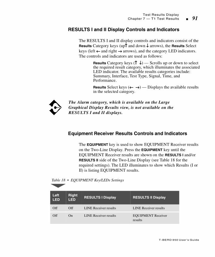
T-BERD 950 User ’s Guide
Test Results DisplayChapter 7 — T1 Test Results 91
RESULTS I and II Display Controls and Indicators
The RESULTS I and II display controls and indicators consist of the Results Category keys (up↑↑↑↑ and down ↓↓↓↓ arrows), the Results Select keys (left ← ← ← ← and right →→→→ arrows), and the category LED indicators. The controls and indicators are used as follows:
Results Category keys (↑↑↑↑ ↓↓↓↓) — Scrolls up or down to select the required result category, which illuminates the associated LED indicator. The available results categories include: Summary, Interface, Test Type, Signal, Time, and Performance.
Results Select keys (← ← ← ← →→→→) — Displays the available results in the selected category.
Equipment Receiver Results Controls and Indicators
The EQUIPMENT key is used to show EQUIPMENT Receiver results on the Two-Line Display. Press the EQUIPMENT key until the EQUIPMENT Receiver results are shown on the RESULTS I and/or RESULTS II side of the Two-Line Display (see Table 18 for the required settings). The LED illuminates to show which Results (I or II) is listing EQUIPMENT results.
The Alarm category, which is available on the Large Graphical Display Results view, is not available on the RESULTS I and II displays.
Table 18 • EQUIPMENT Key/LEDs Settings
LeftLED
RightLED
RESULTS I Display RESULTS II Display
Off Off LINE Receiver results LINE Receiver results
Off On LINE Receiver results EQUIPMENT Receiver results

T-BERD 950 User ’s Guide
T1 Test Results92 Chapter 7 — T1 Test Results
T1 Test Results
The T-BERD 950 test results categories: Summary, Interface, Test Type, Signal, Time, Performance, and Alarms are described in the following subsections as they pertain to the T1 interface.
Summary Category
The Summary category results, view 1:7, automatically shows key results that are non-zero or out-of-specification.
On Off EQUIPMENT Receiver results
LINE Receiver results
On On EQUIPMENT Receiver results
EQUIPMENT Receiver results
TNT results are listed in the TNT configuration setups, however, this section and each option section provides definitions for all test results.
If all results are within specification for the LINE and EQUIPMENT receivers, the message All Results OK appears on both sides of the Two-Line Display.
Table 18 • EQUIPMENT Key/LEDs Settings (Continued)
LeftLED
RightLED
RESULTS I Display RESULTS II Display

T-BERD 950 User ’s Guide
T1 Test ResultsChapter 7 — T1 Test Results 93
Alarm/Status LEDs
Table 19 defines the T-BERD 950 front panel Alarm/Status LEDs as they pertain to the T1 Interface.
Table 19 • Status/Alarm LEDs for T1 Interface
Status/Alarm LED
Description
SIGNAL Illuminates green when the T-BERD 950 detects a T1 signal with frequency equal to 1,544,000 Hz ± 50 Hz and a level greater than -35 dBdsx. The LED indicates at which RECEIVE input (LINE or EQUIPMENT) the signal is detected. The red History LED illuminates when no signal is detected for a period of 150 ns.
FRAME SYNC
Illuminates green when the T-BERD 950 achieves frame synchronization with the received T1 data stream. The LED indicates which RECEIVE input (LINE or EQUIPMENT) the signal is detected. The red History LED illuminates when two out of four received frame bits are in error.
PATTERN SYNC
Illuminates green when the received test pattern is recognized by the T-BERD 950 and pattern synchronization is achieved. The LED indicates if pattern sync is detected on the LINE or EQUIPMENT side. Pattern synchronization depends on receiving a given number of consecutive error-free bits for the specific test pattern.

T-BERD 950 User ’s Guide
T1 Test Results94 Chapter 7 — T1 Test Results
Interface Category Results
The Interface category results, view 2:7, lists all results as described in Table 20.
B8ZS Illuminates green when the T-BERD 950 detects Bipolar 8-Zero Substitution clear-channel coding. The LED indicates which RECEIVE input (LINE or EQUIPMENT) detected the B8ZS coding. The red History LED illuminates when the B8ZS code is no longer detected at the corresponding input.
AIS Illuminates red when the T-BERD 950 detects an Alarm Indication Signal. The LED indicates which RECEIVE input (LINE or EQUIPMENT) the AIS is detected. The red History LED illuminates when the AIS is no longer detected.
YELLOW ALARM
Illuminates red when the T-BERD 950 detects a yellow alarm. The LED indicates which RECEIVE input (LINE or EQUIPMENT) the yellow alarm is detected. The red History LED illuminates when a yellow alarm is no longer detected. Neither the Status nor the History LED illuminates if T1 frame sync has not been achieved.
Table 20 • Interface Category Results
Result Name Description
BPVs (Bipolar Violations)
Counts BPVs detected in the received signal (that are not embedded in valid B8ZS sequences) since start of test.
BPV Seconds (BPV Error Seconds)
Counts test seconds in which a BPV was received.
BPV Rate Calculates ratio of BPVs received over total bits received.
Table 19 • Status/Alarm LEDs for T1 Interface (Continued)
Status/Alarm LED
Description
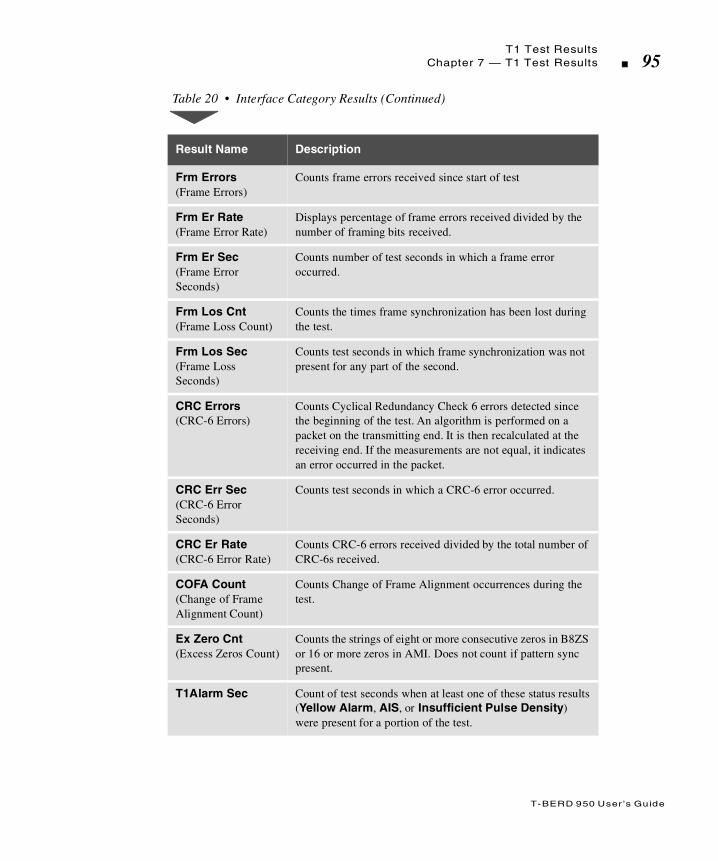
T-BERD 950 User ’s Guide
T1 Test ResultsChapter 7 — T1 Test Results 95
Frm Errors (Frame Errors)
Counts frame errors received since start of test
Frm Er Rate (Frame Error Rate)
Displays percentage of frame errors received divided by the number of framing bits received.
Frm Er Sec(Frame Error Seconds)
Counts number of test seconds in which a frame error occurred.
Frm Los Cnt (Frame Loss Count)
Counts the times frame synchronization has been lost during the test.
Frm Los Sec (Frame Loss Seconds)
Counts test seconds in which frame synchronization was not present for any part of the second.
CRC Errors (CRC-6 Errors)
Counts Cyclical Redundancy Check 6 errors detected since the beginning of the test. An algorithm is performed on a packet on the transmitting end. It is then recalculated at the receiving end. If the measurements are not equal, it indicates an error occurred in the packet.
CRC Err Sec (CRC-6 Error Seconds)
Counts test seconds in which a CRC-6 error occurred.
CRC Er Rate (CRC-6 Error Rate)
Counts CRC-6 errors received divided by the total number of CRC-6s received.
COFA Count(Change of Frame Alignment Count)
Counts Change of Frame Alignment occurrences during the test.
Ex Zero Cnt (Excess Zeros Count)
Counts the strings of eight or more consecutive zeros in B8ZS or 16 or more zeros in AMI. Does not count if pattern sync present.
T1Alarm Sec Count of test seconds when at least one of these status results (Yellow Alarm, AIS, or Insufficient Pulse Density) were present for a portion of the test.
Table 20 • Interface Category Results (Continued)
Result Name Description

T-BERD 950 User ’s Guide
T1 Test Results96 Chapter 7 — T1 Test Results
Rcv Byte (Receive Byte)
Displays the receive data bytes for all channels in binary format.
DDS Rx Byte(DDS Receive Byte)
Displays the receive data byte for the current DSO under test in binary format. Valid only with DDS payload.
DDS Rx Code(DDS Receive Code)
Displays the received control code, by name when one is detected. When no control codes are detected, the message Non Ctrl appears. Table 21 lists the Receive Codes by name and binary. (Codes are transmitted left to right.)
Table 21 • DDS Control Code s
Control Code Binary
ASC (Abnormal Station) N001 1110
BLOCK (Block Code) S000 1010
CHAN LPBK (Channel Loopback) S010 1000
CTRL IDLE (Idle) S111 1110
DATA IDLE (Data Idle) S111 1111
DSU LPBK (DSU Loopback) S010 1100
FEV (Far End Voice) S101 1010
LBE (Loopback Enable) S101 0110
LD ACK S011 0010
LPBK ID (Loopback ID) S101 0001
LSC DSU (Data Service Unit Loopback Select) S011 0001
LSC NEI (Network Element Indicator Loopback Select) S100 0001
MA (MJU Alert) S111 0010
MAP0 (MAP0 Confirmation) S001 0011
Table 20 • Interface Category Results (Continued)
Result Name Description

T-BERD 950 User ’s Guide
T1 Test ResultsChapter 7 — T1 Test Results 97
Test Type Category
The Test Type category results are described in Table 22.
MAP1 (MAP1 Confirmation) S110 1101
MOS (Mux Out Of Sync) N001 1010
OCU LPBK (OCU Loopback) S010 1010
RELEASE (Release Code) S111 1000
TEST (Test Code) S001 1100
TA (Test Alert) S110 1100
TIP (Transition in Progress) S011 1010
UMC (Unassigned Mux Channel) N001 1000
Table 22 • Test Type Category Results
Result Description
Bit Errors Counts the received bits that have a value opposite that of the corresponding transmitted bits, after pattern synchronization has been achieved.
Pat Slips (Pattern Slips)
Counts the total number of pattern slips detected since start of test.
BER (Bit Error Rate)
Displays ratio of bit errors to received pattern data bits.
Errored Sec (Errored Seconds)
Counts test seconds where one or more bit errors occurred.
Table 21 • DDS Control Codes (Continued)
Control Code Binary
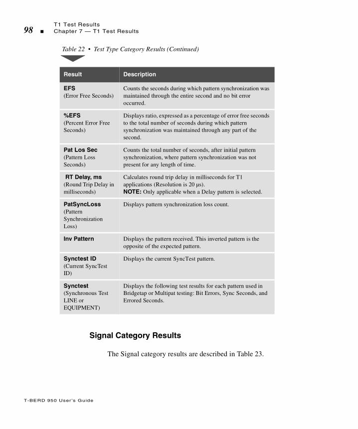
T-BERD 950 User ’s Guide
T1 Test Results98 Chapter 7 — T1 Test Results
Signal Category Results
The Signal category results are described in Table 23.
EFS (Error Free Seconds)
Counts the seconds during which pattern synchronization was maintained through the entire second and no bit error occurred.
%EFS (Percent Error Free Seconds)
Displays ratio, expressed as a percentage of error free seconds to the total number of seconds during which pattern synchronization was maintained through any part of the second.
Pat Los Sec (Pattern Loss Seconds)
Counts the total number of seconds, after initial pattern synchronization, where pattern synchronization was not present for any length of time.
RT Delay, ms (Round Trip Delay in milliseconds)
Calculates round trip delay in milliseconds for T1 applications (Resolution is 20 µs). NOTE: Only applicable when a Delay pattern is selected.
PatSyncLoss (Pattern Synchronization Loss)
Displays pattern synchronization loss count.
Inv Pattern Displays the pattern received. This inverted pattern is the opposite of the expected pattern.
Synctest ID (Current SyncTest ID)
Displays the current SyncTest pattern.
Synctest (Synchronous Test LINE or EQUIPMENT)
Displays the following test results for each pattern used in Bridgetap or Multipat testing: Bit Errors, Sync Seconds, and Errored Seconds.
Table 22 • Test Type Category Results (Continued)
Result Description
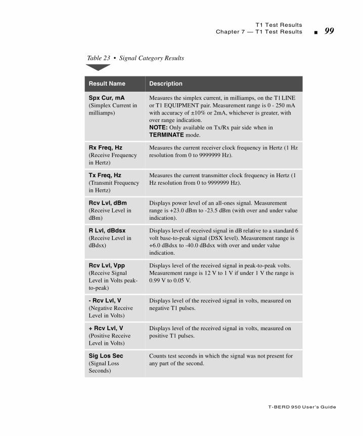
T-BERD 950 User ’s Guide
T1 Test ResultsChapter 7 — T1 Test Results 99
Table 23 • Signal Category Results
Result Name Description
Spx Cur, mA (Simplex Current in milliamps)
Measures the simplex current, in milliamps, on the T1 LINE or T1 EQUIPMENT pair. Measurement range is 0 - 250 mA with accuracy of ±10% or 2mA, whichever is greater, with over range indication. NOTE: Only available on Tx/Rx pair side when in TERMINATE mode.
Rx Freq, Hz (Receive Frequency in Hertz)
Measures the current receiver clock frequency in Hertz (1 Hz resolution from 0 to 9999999 Hz).
Tx Freq, Hz(Transmit Frequency in Hertz)
Measures the current transmitter clock frequency in Hertz (1 Hz resolution from 0 to 9999999 Hz).
Rcv Lvl, dBm (Receive Level in dBm)
Displays power level of an all-ones signal. Measurement range is +23.0 dBm to -23.5 dBm (with over and under value indication).
R Lvl, dBdsx (Receive Level in dBdsx)
Displays level of received signal in dB relative to a standard 6 volt base-to-peak signal (DSX level). Measurement range is +6.0 dBdsx to -40.0 dBdsx with over and under value indication.
Rcv Lvl, Vpp (Receive Signal Level in Volts peak-to-peak)
Displays level of the received signal in peak-to-peak volts. Measurement range is 12 V to 1 V if under 1 V the range is 0.99 V to 0.05 V.
- Rcv Lvl, V (Negative Receive Level in Volts)
Displays level of the received signal in volts, measured on negative T1 pulses.
+ Rcv Lvl, V (Positive Receive Level in Volts)
Displays level of the received signal in volts, measured on positive T1 pulses.
Sig Los Sec (Signal Loss Seconds)
Counts test seconds in which the signal was not present for any part of the second.
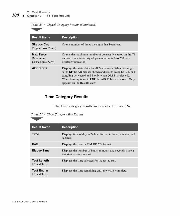
T-BERD 950 User ’s Guide
T1 Test Results100 Chapter 7 — T1 Test Results
Time Category Results
The Time category results are described in Table 24.
Sig Los Cnt (Signal Loss Count)
Counts number of times the signal has been lost.
Max Zeros (Maximum Consecutive Zeros)
Counts the maximum number of consecutive zeros on the T1 receiver since initial signal present (counts 0 to 250 with overflow indication).
ABCD Bits Displays the status bits for all 24 channels. When framing is set to SF the AB bits are shown and results could be 0, 1, or T (toggling between 0 and 1 only when QRSS is selected). When framing is set to ESF the ABCD bits are shown. Only appears on the Results view.
Table 24 • Time Category Test Results
Result Name Description
Time Displays time of day in 24 hour format in hours, minutes, and seconds.
Date Displays the date in MM:DD:YY format.
Elapse Time Displays the number of hours, minutes, and seconds since a test start or a test restart.
Test Length(Timed Test)
Displays the time selected for the test to run.
Test End ln(Timed Test)
Displays the time remaining until the test is complete.
Table 23 • Signal Category Results (Continued)
Result Name Description

T-BERD 950 User ’s Guide
T1 Test ResultsChapter 7 — T1 Test Results 101
Performance Category Results
The Performance category results are described in Table 25.
Power Loss Displays the number of times the unit has powered on since the RESTART key was pressed.
Batt Charge Displays amount of battery charge remaining.
Batt Index(Battery Performance Index)
Indicates the amount of total charge capacity available when the batteries are fully charged.
Table 25 • Performance Category Results
Result Description
G.821 EFS (Error Free Seconds, G.821)
Counts number of available seconds in which no bit errors occurred.
G.821 %EFS(Percent Error Free Seconds, G.821)
Calculates ratio of available seconds in which no errors were detected to total number of available seconds.
SES (Severely Errored Seconds, G.821)
Counts the seconds in which the bit error ratio was greater
than 10-3 within available time.
%SES(Percent Severely Errored Seconds, G.821)
Displays percentage of severely errored seconds to the number of available seconds.
Deg Min (Degraded Minutes)
Counts the blocks of 60 non-severely errored, available
seconds in which the average BER was worse than 10-6.
Table 24 • Time Category Test Results (Continued)
Result Name Description
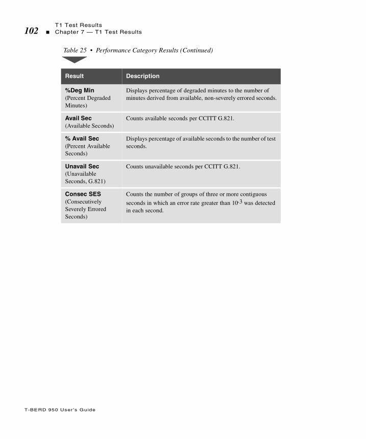
T-BERD 950 User ’s Guide
T1 Test Results102 Chapter 7 — T1 Test Results
%Deg Min (Percent Degraded Minutes)
Displays percentage of degraded minutes to the number of minutes derived from available, non-severely errored seconds.
Avail Sec (Available Seconds)
Counts available seconds per CCITT G.821.
% Avail Sec (Percent Available Seconds)
Displays percentage of available seconds to the number of test seconds.
Unavail Sec (Unavailable Seconds, G.821)
Counts unavailable seconds per CCITT G.821.
Consec SES (Consecutively Severely Errored Seconds)
Counts the number of groups of three or more contiguous
seconds in which an error rate greater than 10-3 was detected in each second.
Table 25 • Performance Category Results (Continued)
Result Description
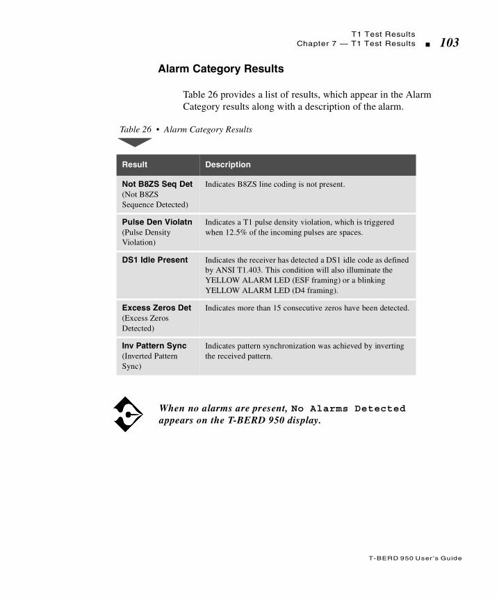
T-BERD 950 User ’s Guide
T1 Test ResultsChapter 7 — T1 Test Results 103
Alarm Category Results
Table 26 provides a list of results, which appear in the Alarm Category results along with a description of the alarm.
Table 26 • Alarm Category Results
Result Description
Not B8ZS Seq Det(Not B8ZSSequence Detected)
Indicates B8ZS line coding is not present.
Pulse Den Violatn (Pulse DensityViolation)
Indicates a T1 pulse density violation, which is triggered when 12.5% of the incoming pulses are spaces.
DS1 Idle Present Indicates the receiver has detected a DS1 idle code as defined by ANSI T1.403. This condition will also illuminate the YELLOW ALARM LED (ESF framing) or a blinking YELLOW ALARM LED (D4 framing).
Excess Zeros Det(Excess ZerosDetected)
Indicates more than 15 consecutive zeros have been detected.
Inv Pattern Sync(Inverted PatternSync)
Indicates pattern synchronization was achieved by inverting the received pattern.
When no alarms are present, No Alarms Detected appears on the T-BERD 950 display.

T-BERD 950 User ’s Guide
T1 Test Results104 Chapter 7 — T1 Test Results

T
T-BERD 950 User ’s Guide
his chapter describes how to print information from the T-BERD 950 manually and at user-specified intervals.
Chap te r8 Printer Operation

T-BERD 950 User ’s Guide
Printer Configuration106 Chapter 8 — Printer Operation
Printer Configuration
The T-BERD 950 printer function supports common data rates up to 9600 bps (300, 1200, 2400, and 9600) of even, odd, or no parity. It supports the line terminator (CR, or CR/LF, LF, NONE) for the printer output. Standard RS-232 out-of-band flow control, stop bits, and data length are also supported. It supports the Acterna PR-40A (DPU-411) and compatible printers.
Printing
The T-BERD 950 printer performs manual prints by pressing the PRINT SCREEN softkey. This generates a print of the current view on the Large Graphical Display (“Home,” “Setup,” “Results,” or “System”).
The T-BERD 950 uses the 39 column print format. Prints contain headers that show the product identifier, print type, site ID, and the date and time of the print. The site and ID fields can be configured from the System view. The time stamp is captured when screen capture is obtained for the print.
Manual Print Screen
With the T-BERD 950 printer, you can print the contents of the currently-active graphical display. Press the PRINT SCREEN softkey. Except for the screen borders and softkeys, the contents print as shown on the display. Figure 20 is an example of the T-BERD 950 Print Screen.

T-BERD 950 User ’s Guide
Printer ConfigurationChapter 8 — Printer Operation 107
Figure 20 • T-BERD 950 Print Screen
Timed Print Screen
The T-BERD 950 prints the current view at a specified interval. Select this option as described in “User Interface Configuration Requirements” on page 108. Specify the time interval up to 999 hours and 99 minutes.
Non-Volatile Storage of Prints
When a print is initiated, data is stored in non-volatile RAM (NOVRAM). This allows you to turn off the T-BERD 950 and retain the print buffers that have not been printed.
T-BERD 950 Print Screen13:44:24 07/17/1998 SITE: ID:---------------------------------------Test Type T1-BERT LINEBit Errors 3Pat Slips 0BER 5. E-08Errored Sec 2EFS 36%EFS 94.74%Pat Los Sec 0RT Delay,ms N/APatSyncLoss 0Inv Pattern FALSESynctest ID N/ASynctest - Line N/A

T-BERD 950 User ’s Guide
Printer Configuration108 Chapter 8 — Printer Operation
The T-BERD 950 printer has a fixed amount of NOVRAM reserved for storing print data. It can store at least 10 prints. These prints can be one or more manual or timed prints. If a print request is received and there is not enough memory to store the print data, the T-BERD 950 does not store the print data. Instead, it alerts you to this condition by flashing the Print Buffer Full message on the Two-Line display.
To temporarily clear the Print Buffer Full message, you can disable automatic printing in the System view or press the RESTART key. The message will reappear when another print request generates and the buffer is full, which requires you to clear the condition again. The Two-Line message is removed when the buffer becomes available.
You can use a configuration from the System view to clear the print buffer stored in NOVRAM. After setting the configuration to YES, you are prompted to confirm the operation using the softkeys. You can Confirm to clear the buffer or Cancel the operation. The print buffer is cleared when you change the software version.
User Interface Configuration Requirements
The System view is used to configure the Printer option for the T-BERD 950. The SCROLL keys are used to control this selection area.
Printer Info — Select one of the following choices (default is HIDE):
HIDE — Hides the options for the printer port (default).
DISPLAY — Shows other options to set up the print configuration.
With the T-BERD 950 printer option, you can store screen information when you are out in the field. When you connect the analyzer to a printer at a later time, the T-BERD 950 will resume printing until the buffers are empty.

T-BERD 950 User ’s Guide
Printer ConfigurationChapter 8 — Printer Operation 109
Site — Identifies the Site on the Print Header. Enter six characters of hex digit or leave blank (default is blank).
Id — Identifies other characteristics of the site on the Print Header. Enter two characters of 0-9 or leave blank (default is blank).
Timed Prints — Prints the current views test results at a specified interval. Select ON or OFF.
When ON is selected, the following line appears to set the print time.
Timed Prints (HHH:MM ) — Set the print time using the keypad. (Default is 1:00 (one hour)).
Clear Print Buffer — Use the Softkeys to select YES or NO. The default is NO. A dialog screen pops up to confirm your selection.
Printer Port Info — Provides Printer Port options. Set the options based on your printer configuration. The default is HIDE.
HIDE — Hides the options.
DISPLAY — Shows other options to set up the printer port.
Data Rate — Select the Baud Rate of 1200, 2400, 4800, 9600 (default is 9600).
Stop Bits — Select the Stop Bits 1, 1.5, or 2 (default is 1).
Data Length — Select the Data length 7 or 8 (default is 8).
Parity — Select Parity of EVEN, ODD, or NONE (default is NONE).
If Printer Info DISPLAY is selected, the remainder of the options are shown on the System view.
If Printer Port Info DISPLAY is selected, the remainder of the options are shown on the System view.

T-BERD 950 User ’s Guide
Printer Configuration110 Chapter 8 — Printer Operation
Terminator — Select the termination of the print (default is CRLF).
CRLF — Carriage Return and Line Feed
CR — Carriage Return only
LF — Line Feed only
NONE — None

T
T-BERD 950 User ’s Guide
his chapter provides operating information for the T-BERD 950 Communications Analyzer options.
Chap te r9 Options

T-BERD 950 User ’s Guide
Available Options112 Chapter 9 — Options
Available Options
The available options are described in separate subsections.
Digital Data System Local Loop Option
Frame Relay Option
ISDN Primary Rate Interface Option
Signaling Option
PCM TIMS Option
ISDN Basic Rate Interface Option
10BaseT/Ethernet Option
T
T-BERD 950 User ’s Manual
his section provides step-by-step instructions for the Digital DataSystem Local Loop (DDS LL) Option for the T-BERD 950 and
discusses the following topics:
Option Description
TNT Setups
Manual Test Setups
Test Results
DDS LL Option

Option Description114 Chapter 9 — DDS LL Option
T-BERD 950 User ’s Manual
Option Description
The DDS Local Loop option allows you to test from and analyze the DDS four-wire local loop. The electrical interface for the option is the eight position RJ-45 connector. This connector is compatible with both the RJ-45 (keyed, 8 position, 8 conductor) and RJ-48 (non-keyed) modular plugs. Only four conductors are used on the connector; Table 27 explains the RJ-45 connector pin assignments in the various operating modes of the DDS Local Loop option.
Table 27 • RJ-45 Pin Assignments
Pin No.
FunctionPin No.
Function
OCU-DP Emulation Mode
1 R (Receive Data, Ring Lead) 5 Not Used
2 T (Receive Data, Tip Lead) 6 Not Used
3 Not Used 7 T1 (Transmit Data, Tip Lead)
4 Not Used 8 R1 (Transmit Data, Ring Lead)
DSU/CSU Emulation Mode
1 R (Transmit Data, Ring Lead) 5 Not Used
2 T (Transmit Data, Tip Lead) 6 Not Used
3 Not Used 7 T1 (Receive Data, Tip Lead)
4 Not Used 8 R1 (Receive Data, Ring Lead)
Monitor Mode
1 R (Receive Data, Ring Lead) 5 Not Used
2 T (Receive Data, Tip Lead) 6 Not Used
3 Not Used 7 T1 (Receive Data, Tip Lead)
4 Not Used 8 R1 (Receive Data, Ring Lead)

Option DescriptionChapter 9 — DDS LL Option 115
T-BERD 950 User ’s Manual
Option Specifications
Table 28 describes the specifications for the DDS Local Loop option.
Table 28 • Option Specification s
Item Specification
Data Formats Standard DDS — Two information bands are used: the primary data channel, and out of band control codes (transmitted as BPV sequences).DDS with Secondary Channel — Three information bands are used: the primary data channel, the secondary channel, and inband control codes.
Primary Channel Data Rates 2.4, 4.8, 9.6, 19.2, 38.4, 56, and 64 kbps.
Secondary Channel Data Only the Idle, 511, and 2047 BER testing patterns are available — inband flow control is not available.
Clock Source Recovered timing from received signal or internal synthesizer (menu selectable).
Receive SignalConnection:
Termination ImpedanceBridging ImpedanceOperating Range
OCU-DP mode: RJ-45 pins 1 & 2. DSU/CSU mode: RJ-45 pins 7 & 8.MONITOR mode: RJ-45 pins 1 & 2 and 7 & 8.Balanced, 135 Ω ±5%.Greater than 1900 Ω.+6.0 dB to -45 dB minimum (56 kbps and 64 kbps) -OR- +6.0 dB to -40 dB minimum (all other data rates).
Transmit SignalConnection:
Termination ImpedanceOutput Levels
OCU-DP mode: RJ-45: pins 7 & 8.DSU/CSU mode: RJ-45: pins 1& 2.Balanced, 135 Ω, ±5%.0, -3, -6, and -9 dB of simulated cable attenuation.
Test Modes TERMINATE, MONITOR or LLB (Line Loop Back)
Emulation Modes DSU/CSU, OCU-DP or Metallic

Option Description116 Chapter 9 — DDS LL Option
T-BERD 950 User ’s Manual
Option Messages
The messages that may appear on the analyzer front panel during testing are provided in Table 29..
Simplex CurrentInput LevelMeasurement range
OCU-DP mode current output
±30 mA maximum±26 mA with an accuracy of ±10% or 2mA
4 mA to 20 mA depending on the length of the span
Error InsertionOperationError rateError insert type
Single or continuous1E-3Logic, BPV, L&BPV, or Frame. Available on Primary or Secondary Channel
Loop Response V.54DSU/CSUDisabled
Table 29 • Option Messages
Message Category Message
Receive Messages Preexisting Loop PresentIn LoopbackSealing Current Loss (Alarm message)
Originating Messages Transmitting Loop UpTransmitting Loop Down
Table 28 • Option Specifications (Continued)
Item Specification
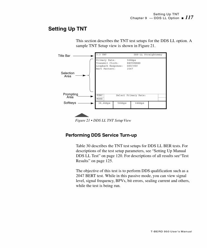
Setting Up TNTChapter 9 — DDS LL Option 117
T-BERD 950 User ’s Manual
Setting Up TNT
This section describes the TNT test setups for the DDS LL option. A sample TNT Setup view is shown in Figure 21.
Figure 21 • DDS LL TNT Setup View
Performing DDS Service Turn-up
Table 30 describes the TNT test setups for DDS LL BER tests. For descriptions of the test setup parameters, see “Setting Up Manual DDS LL Test” on page 120. For descriptions of all results see“Test Results” on page 125.
The objective of this test is to perform DDS qualification such as a 2047 BERT test. While in this passive mode, you can view signal level, signal frequency, BPVs, bit errors, sealing current and others, while the test is being run.
Title Bar
SelectionArea
Primary Rate: 56kbpsTransmit Clock: RECOVEREDLoopback Response: DSU/CSUBert Pattern: 2047
Prompting
Softkeys
3:3 TNT DDS-LL Straightaway
FUNC
MORE
Select Primary Rate:
56kbps 64kbps38,4kbps
Area

Setting Up TNT118 Chapter 9 — DDS LL Option
T-BERD 950 User ’s Manual
Troubleshooting DDS Service
Table 31 describes the TNT test setup to troubleshoot DDS service. For descriptions of the test setup parameters, see “Setting Up Manual DDS LL Test” on page 120. For descriptions of all results see“Test Results” on page 125.
The objective of this test is to perform DDS qualification such as a 2047 BERT test. In this mode, you can view signal level, signal frequency, BPVs, bit errors, sealing current, and others, while the test is running.
Table 30 • DDS LL BERT Turnup
Test TNT Setup TNT Results
RESPOND TO LOOPBACK(CSU/DSU Emulation)
In this scenario, the T-BERD 950 is being used as a loopback device. Ideally, you are waiting for a loopback code to be sent from a centralized tester or from a test set located in the CO.
Primary Rate (56K)Loopback Response (DSU/CSU)Bert Pattern (AUTO)
Bit ErrorsPat SlipsBPVsDDS Frm ErrsSeal Cur, mARcv Freq, HzRcv Lvl, dB
STRAIGHTAWAY(Emulate CSU/DSU)
In this scenario, the T-BERD 950 is being used as one test set at customer premise, while another test set is located at the far end, typically the CO at a DSX panel. Testing and analysis is performed in both directions. This is a better method of sectionalizing a trouble and service verification during turnup.
Primary Rate (56K)Transmit Clock (Recovered)Loopback Response (DSU/CSU)Bert Pattern (2047)
Bit ErrorsPat SlipsBPVsDDS Frm ErrsSeal Cur, mARcv Freq, HzRcv Lvl, dB

Setting Up TNTChapter 9 — DDS LL Option 119
T-BERD 950 User ’s Manual
Monitoring DDS Service
Table 32 describes the TNT test setup to monitor at the DDS interface. For descriptions of the test setup parameters, see “Setting Up Manual DDS LL Test” on page 120. For descriptions of all results see“Test Results” on page 125.
The purpose of the DDS LL monitor test is to passively monitor various DDS LL results while the test is being run. Monitor the timing between two DDS signals for timing slips and other results.
Table 31 • DDS LL Interface DDS Troubleshooting
Test TNT Setup TNT Results
SEND CSU LOOPBACK (OCU-DP or Office Card emulation)
This scenario assumes that the DDS physical layer has already been tested. This is to be used as a method of troubleshooting the customer’s CSU/DSU to isolate the provider’s network as a source of the problem. The technician can use a CSU/DSU loop code to loop up the CSU/DSU and perform BER testing. This is a one-person test.
Primary Rate (56K)Loopcode (Tx) (CSU/DSU)Bert Pattern (2047)
Bit ErrorsBPVsPat SlipsDDS Frm ErrsSeal Cur, mARcv Freq, HzRcv Lvl, dB
Table 32 • DDS LL Monitor
Test TNT Setup TNT Results
BERT
In this scenario, you can connect to the monitor point and review the results.
Primary Rate (56K)Bert Pattern (AUTO)
BPVsDDS Frm ErrsSeal Cur, mARcv Freq, HzRcv Lvl, dBTiming Slips
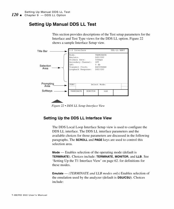
Setting Up Manual DDS LL Test120 Chapter 9 — DDS LL Option
T-BERD 950 User ’s Manual
Setting Up Manual DDS LL Test
This section provides descriptions of the Test setup parameters for the Interface and Test Type views for the DDS LL option. Figure 22 shows a sample Interface Setup view.
Figure 22 • DDS LL Setup Interface View
Setting Up the DDS LL Interface View
The DDS Local Loop Interface Setup view is used to configure the DDS LL interface. The DDS LL interface parameters and the available choices for those parameters are discussed in the following paragraphs. The SCROLL and PAGE keys are used to control this selection area.
Mode — Enables selection of the operating mode (default is TERMINATE). Choices include: TERMINATE, MONITOR, and LLB. See ‘Setting Up the T1 Interface View’ on page 62. for definitions for these modes.
Emulate — (TERMINATE and LLB modes only) Enables selection of the emulation used by the analyzer (default is DSU/CSU). Choices include:
Title Bar
SelectionArea
Mode: TERMINATEEmulate: DSU/CSUPrimary Rate: 56kbpsSecondary Channel: OFFLBO: 0 dbTransmit Clock: RECOVEREDLoopback Response: DSU/CSU
Prompting
Softkeys
1:2 Interface DDL-LL BERT
FUNC Select Mode:
MONITOR LLBTERMINATE
Area

Setting Up Manual DDS LL TestChapter 9 — DDS LL Option 121
T-BERD 950 User ’s Manual
DSU/CSU — In DSU/CSU emulation, the analyzer receives on the T1/R1 pair and transmits on the T/R pair. In this emulation type, choices include:
Transmit Clock — Enables selection of the transmit timing source (default is RECOVERED). Choices include:
RECOVERED — Selects the LINE receiver clock as the transmit timing source.
INTERNAL — Selects the internal frequency synthesizer as the transmit timing source.
Loopback Response — Selects the type of loop code response performed by the analyzer (default is DISABLED). The choice is:
V.54 — Enables the T-BERD 950 to loop back when it receives a V.54 loop code.
DSU/CSU — (not available in OCU-DP emulation) Enables the T-BERD 950 to loop back when it receives a DSU/CSU loop code.
DISABLED — The T-BERD 950 will not respond to received loop codes.
OCU-DP — In OCU-DP emulation, the analyzer receives on the T/R pair and transmits on the T1/R1 pair. The T-BERD 950 automatically sets the transmit clock to internal. In this emulation type, choices include:
When the T-BERD 950 is in DSU/CSU emulation, the V.54 loop code is sent when the LOOP UP key is pressed.
In the DSU/CSU emulation, DSU/CSU Loop Resp responds to both alternating and latching CSU loop back requests and alternating and latching DSU loopback requests. Latching DSU is valid in framed formats (secondary channel and 64kbps) only.
Setting Up Manual DDS LL Test122 Chapter 9 — DDS LL Option
T-BERD 950 User ’s Manual
Loopback Response — Selects the type of loop code response performed by the analyzer (default is DISABLED). Choices include:
V.54 — Enables the T-BERD 950 to loop back when it receives a V.54 loop code.
DISABLED — The T-BERD 950 will not respond to received loop codes.
Loopcode (Tx) — Selects the type of loop code transmitted by the analyzer (default is V.54). Choices include:
V.54 — V.54 loop codes are transmitted by the analyzer.
LATCHING CSU — Selects latching CSU (sealing current reversal).
METALLIC — Enables metallic loop testing and tip-ring short metallic testing. Choices include:
Shorts — Enables selection of the type of cable test to be performed (default is TX-to-RX). Choices include:
TX-to-RX — Connects the transmit tip (T) to the receive tip (T1) and the transmit ring (R) to the receive ring (R1), via a metallic short.
TIPS-to-RINGS — Connects the transmit tip (T) to the transmit ring (R) and the receive tip (T1) to the receive ring (R1), via a metallic short.
Primary Rate — (TERMINATE and LLB modes) Enables selection of the data rate for transmission and analysis (default is 56kbps). Choices include: 2.4, 4.8, 9.6, 19.2, 38.4, 56, or 64kbps.
The T-BERD 950, when configured for OCU-DP mode, can drive a non-repeatered span up to 18,000 feet. The OCU-DP mode sealing current conforms to 4-20mA, 7-28V which will not power a repeater located on the span.
In Metallic emulation, no DDS LL results are gathered and BER testing is not performed.

Setting Up Manual DDS LL TestChapter 9 — DDS LL Option 123
T-BERD 950 User ’s Manual
When Primary Rate is set to any rate except 64kbps, the secondary channel choices include:
Secondary Channel — Turns the secondary channel ON or OFF (default is OFF). When set to ON, the following choice appears:
Analysis Channel — Selects the channel on which analysis is performed (default is PRIMARY). Choices include:
PRIMARY — Performs analysis on the Primary channel.
SECONDARY — Performs analysis on the Secondary channel.
LBO — (TERMINATE mode only) Enables emulation of the different cable losses for the output signal level (default is 0dB). The selected cable loss affects the transmit data only at the connectors. Choices include:
0 dB — Sets the primary output (TX) to zero or no line build-out (0 dB attenuation).
-3 dB — Provides -3 dB line build-out, attenuating the output with 3 dB of simulated cable loss.
-6 dB — Provides -6 dB line build-out, attenuating the output with 6 dB of simulated cable loss.
-9 dB — Provides -9 dB line build-out, attenuating the output with 9 dB of simulated cable loss.
Setting Up the DDS LL Test Type View
The Test Type view allows you to configure the type of test to be performed.

Setting Up Manual DDS LL Test124 Chapter 9 — DDS LL Option
T-BERD 950 User ’s Manual
Figure 23 • DDS LL Setup Test Type View
Bert Pattern — Select the appropriate BERT pattern. For descriptions of all BERT patterns see “Setting Up the T1 Test Type View” on page 80.
Sec Channel Pattern — Selects the type of data inserted on the secondary channel (default is 511). Choices include:
IDLE — Inserts idle code on the secondary channel.
511 — Inserts the 511 BER test pattern on the secondary channel.
2047 — Inserts the 2047 BER test pattern on the secondary channel.
Bert Block Type — Enables selection of the block length for the currently selected pattern (default is PATTERN LENGTH). Choices include:
PATTERN LENGTH — Sets the block length to the length of the currently selected pattern.
USER DEFINED — Enables the user to set a specific block length for the selected pattern. Choices include:
Bert Block Length — Enables setting the block length to any value between 50 and 100000 (default is 1000). The keypad is used to enter the desired value.
Title Bar
SelectionArea
Bert Pattern: 2047Bert Block Error: PATTERN LENGTHError Insert Type: LOGIC
Prompting
Softkeys
2:2 Test Type DDL-LL BERT
FUNC
MORE
Select Bert Pattern:
2047QRS T1-1Min/Max
T1-2/962047
Area

Test ResultsChapter 9 — DDS LL Option 125
T-BERD 950 User ’s Manual
Error Insert Type — (TERMINATE mode only) Enables selection of the type of error to be inserted in the data stream when the ERROR INSERT key is pressed (default is LOGIC). Choices include:
LOGIC — Enables insertion of bit (logic) errors. Single errors or an error rate can be selected.
BPV — Enables insertion of bipolar violation errors. Single errors or an error rate can be selected.
L&BPV — Enables insertion of logic and bipolar violation errors. Single errors or an error rate can be selected.
FRAME — Enables insertion of a single frame error (Secondary Channel must be set to ON).
Test Results
Test results for the DDS LL option appear on the analyzer Two-Line Display. The Two-Line Display and associated controls and indicators are located on the front panel above the keypad. See ‘Test Results Display’ on page 90. for a detailed description of the Two-Line Display.
Test results are also shown on the Large Graphical Display Results view. See ‘Results View’ on page 33. for a detailed description of the Large Graphical Display. A typical DDS LL Results view is shown in Figure 24.
The logic and BPV errors are generated independently and are not guaranteed to coincide (e.g., the logic and BPV errors may not be generated on the same bit). In addition, the amount of errors inserted is determined by the use of the front panel ERROR INSERT key. Press the ERROR INSERT key once to insert a single error. Press and hold the ERROR INSERT key for approximately two (2) seconds to insert errors at a rate of 1x10⁻³. Press the ERROR INSERT key again to cancel the rate.

Test Results126 Chapter 9 — DDS LL Option
T-BERD 950 User ’s Manual
Figure 24 • DDS LL Results Test Type View
Status/Alarm LEDs
The SIGNAL Status/Alarm LED illuminates green when a valid DDS signal is being received.
Summary Category Results
The Summary category automatically lists key results that are out of specification. If all results are within specification for the LINE or EQUIPMENT receiver, the message All Results OK appears on the appropriate side of the Two-Line Display.
A red illuminated LED indicates the Status/Alarm condition was previously true or present, since the start of the current test.
For Test Type, Time, and Performance results see T1 “Test Results” on page 125.
Title Bar
SelectionArea
PRIMARYBit ErrorsPat SlipsBERErrored SecERS% EFSPat Los SecRT Delay, msPatSyncLossInv PatternBlock Count
Prompting
Softkeys
3:7 Test Type DDS-LL-BERT
Press HELP for Additional Result Information.
PRINTSCREEN
Area
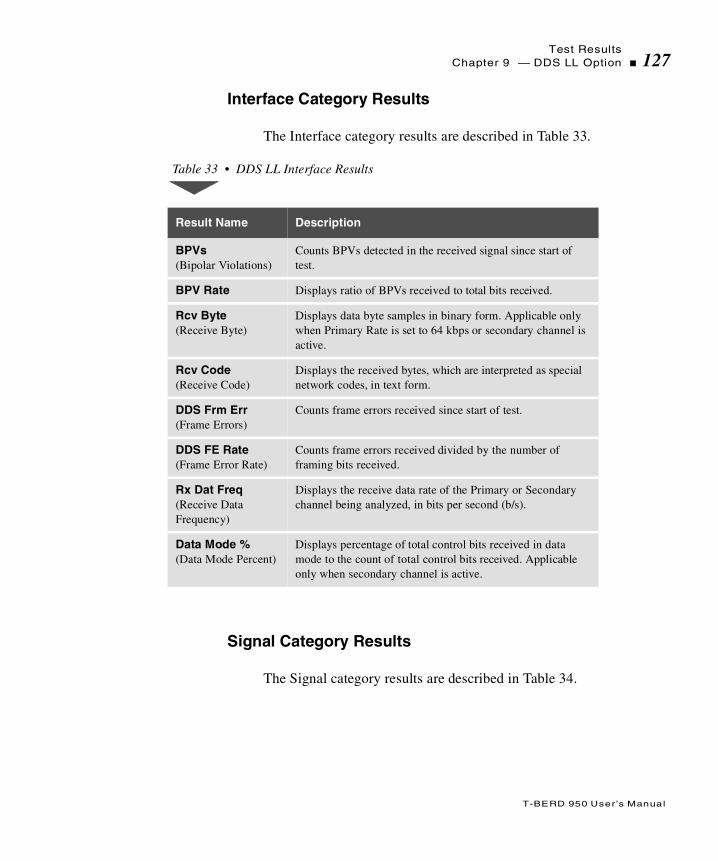
Test ResultsChapter 9 — DDS LL Option 127
T-BERD 950 User ’s Manual
Interface Category Results
The Interface category results are described in Table 33.
Signal Category Results
The Signal category results are described in Table 34.
Table 33 • DDS LL Interface Results
Result Name Description
BPVs (Bipolar Violations)
Counts BPVs detected in the received signal since start of test.
BPV Rate Displays ratio of BPVs received to total bits received.
Rcv Byte (Receive Byte)
Displays data byte samples in binary form. Applicable only when Primary Rate is set to 64 kbps or secondary channel is active.
Rcv Code (Receive Code)
Displays the received bytes, which are interpreted as special network codes, in text form.
DDS Frm Err (Frame Errors)
Counts frame errors received since start of test.
DDS FE Rate (Frame Error Rate)
Counts frame errors received divided by the number of framing bits received.
Rx Dat Freq (Receive Data Frequency)
Displays the receive data rate of the Primary or Secondary channel being analyzed, in bits per second (b/s).
Data Mode % (Data Mode Percent)
Displays percentage of total control bits received in data mode to the count of total control bits received. Applicable only when secondary channel is active.

Test Results128 Chapter 9 — DDS LL Option
T-BERD 950 User ’s Manual
Alarm Messages
Table 35 describes Sealing Current Range, which appears on the Results Alarms view. When no alarms are present, No Alarms Detected appears on the display.
Table 34 • DDS LL Signal Results
Result Name Description
Rcv Lvl, dB (Receive Level in dB)
Displays power level of an all-ones signal measured in dB. Measurement range is 0 dB to -45.0 dB.
Rcv Lvl, Vp (Receiver Signal Level in Volts peak-to-peak)
Displays level of received signal in peak-to-peak volts. Measurement range is 1.00 V to 4.00 V if under 1.00 V the range is 0 V to 0.999 V.
Seal Cur, mA (Sealing Current)
Measures the loop up or loop down sealing current, in milliamps. Applicable in MONITOR and EMULATE DSU/CSU modes only.
Rcv Freq, Hz (Receive Frequency, in Hertz)
Displays current measurement of the receiver clock frequency in Hertz (.01 Hz resolution from 0000.00 to 9999.99 Hz; 0.1 Hz resolution from 10000.0 to 99999.9 Hz).
Timing Slip Measures the difference between the T/R and T1/R1 receivers while in MONITOR mode.
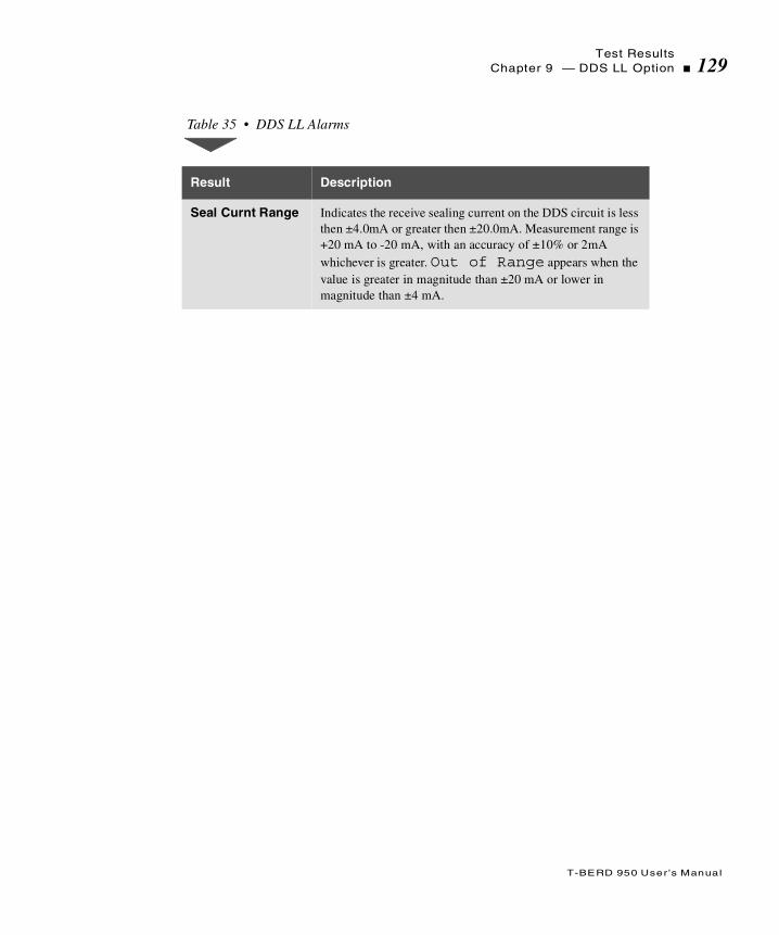
Test ResultsChapter 9 — DDS LL Option 129
T-BERD 950 User ’s Manual
Table 35 • DDS LL Alarms
Result Description
Seal Curnt Range Indicates the receive sealing current on the DDS circuit is less then ±4.0mA or greater then ±20.0mA. Measurement range is +20 mA to -20 mA, with an accuracy of ±10% or 2mA whichever is greater. Out of Range appears when the value is greater in magnitude than ±20 mA or lower in magnitude than ±4 mA.

Test Results130 Chapter 9 — DDS LL Option
T-BERD 950 User ’s Manual

T
T-BERD 950 User ’s Manual
his section provides step-by-step instructions for the Frame Relayoption for the T-BERD 950 and discusses the following topics:
Option Description
TNT Setups
Manual Test Setups
Test Results
Frame Relay Option
Option Description132 Chapter 9 — Frame Relay Option
T-BERD 950 User ’s Manual
Option Description
The Frame Relay option, in conjunction with the Protocol Services Board option, enables the T-BERD 950 Communications Analyzer to transmit and receive frame relay packets via the T1 interfaces (LINE or EQUIPMENT), the Optional DDS LL or Datacom interfaces.
The Frame Relay option enables generation of frame relay packets with various traffic scenarios. The scenarios include varying the frame size and link utilization (throughput) and the ability to send data in a random or bursty manner. In addition, the Frame Relay option enables the collection of basic protocol statistics concerning the frame relay circuit under test. Test results are collected on one specific Data Link Connection Identifier (DLCI) and on the aggregate frames for all DLCIs.
Operating Modes
The Frame Relay option operates in one of two modes, either Terminate mode (D&I mode is also available for T1 interface) or Monitor mode. The following paragraphs discuss each mode in detail.
Terminate Mode
In Terminate mode the option utilizes one receiver/transmitter pair. The option transmits/receives frame relay packets at rates up to 1.544 Mbps. The analyzer can emulate the following types of link management (CPE only): LMI Rev.1 or T1.617 Annex D. In addition, the analyzer can transmit TTC test frames (see Figure 25 on page 133) to test provisioned circuits, in a loopback configuration or in conjunction with another T-BERD 950 (or a TTC FIREBERD 6000 with the Frame Relay option installed).

Option DescriptionChapter 9 — Frame Relay Option 133
T-BERD 950 User ’s Manual
Figure 25 • TTC Test Frame Format
Monitor Mode
Monitor mode lets you monitor frame relay circuits from both receivers simultaneously and accumulate basic layer 2 statistics. The accumulated results for each receiver can appear separately.
Flag
Frame Relay
Header
0 0 0 0 0 0 1 1 Control (UI) = 0x03
0 0 0 0 0 0 0 0 Pad
1 0 0 0 0 0 0 0 NLPID = SNAP (0x80)
0 0 0 0 0 0 0 0
0 1 0 0 0 0 0 0
0 1 0 0 1 1 0 1
0 0 0 0 0 0 0 0
OUI = TTC (0x00404d)
0 0 0 0 0 0 0 0 PID = Sequence Number Only Test
Sequence Number (msb)
Sequence Number (lsbv)
UDF Length (msb)
UDF Length (lsb)
FCS (msb)
FCS (lsb)
Flag
.
.
.
.
The “QUICK BROWN FOX” patternor a “User-Defined” pattern repeated for the length of the frame
(0x0001)
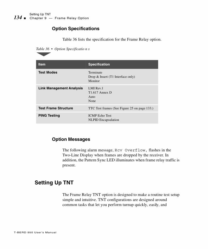
Setting Up TNT134 Chapter 9 — Frame Relay Option
T-BERD 950 User ’s Manual
Option Specifications
Table 36 lists the specification for the Frame Relay option.
Option Messages
The following alarm message, Rcv Overflow, flashes in the Two-Line Display when frames are dropped by the receiver. In addition, the Pattern Sync LED illuminates when frame relay traffic is present.
Setting Up TNT
The Frame Relay TNT option is designed to make a routine test setup simple and intuitive. TNT configurations are designed around common tasks that let you perform turnup quickly, easily, and
Table 36 • Option Specificatio n s
Item Specification
Test Modes TerminateDrop & Insert (T1 Interface only)Monitor
Link Management Analysis LMI Rev.1T1.617 Annex DAutoNone
Test Frame Structure TTC Test frames (See Figure 25 on page 133.)
PING Testing ICMP Echo TestNLPID Encapsulation

Setting Up TNTChapter 9 — Frame Relay Option 135
T-BERD 950 User ’s Manual
accurately. Select the interface, task, and test. TNT automatically sets certain parameters based on common test scenarios, minimizing configuration settings and key presses.
Performing T1 Interface Frame Relay Turn-up
Table 37 lists the TNT setups for the T1/FT1 Frame Relay Turn-up test in Router Emulation. For descriptions of the test setup parameters, see “Setting Up Manual Frame Relay Test” on page 141. For descriptions of all results see“Test Results” on page 146.
The three tests listed in Table 37, Table 38, and Table 39 perform different functionality testing for frame relay service using the various interfaces, T1, T1 DDS, and DDS LL. These tests verify that the customer is properly configured making sure that the Link Management Interface (LMI) is functioning properly, the actual frame relay service operates at the Committed Information Rate (CIR), and PING checks connectivity to a far-end router.
The objective of the LMI/PVC Check verifies that the Link Management Interface (LMI) is functioning properly, and that all DLCIs have Permanent Virtual Circuits (PVCs) that are properly configured and active.
The objective of the CIR Check verifies that the customer is provided actual frame relay service at their Committed Information Rate (CIR), without losing frames due to congestion, improper Discard Eligibility (DE) flags, incorrect PVCs configurations, and others. Physical layer results may also be viewed.
The objective of the PING Test is to check connectivity to a far-end router without taking it out-of-service. In this mode, the you can send IP Pings to an installed IP address (typically another router) in the network. The goal is to ensure that all IP PING messages sent to the far-end device are responded back with an echo reply.
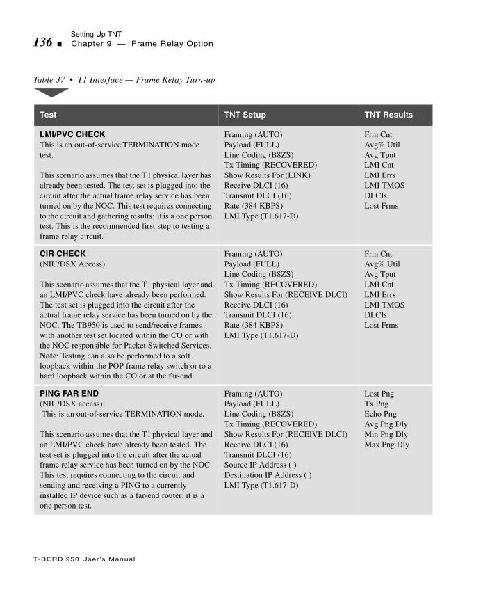
Setting Up TNT136 Chapter 9 — Frame Relay Option
T-BERD 950 User ’s Manual
Table 37 • T1 Interface — Frame Relay Turn-up
Test TNT Setup TNT Results
LMI/PVC CHECKThis is an out-of-service TERMINATION mode test.
This scenario assumes that the T1 physical layer has already been tested. The test set is plugged into the circuit after the actual frame relay service has been turned on by the NOC. This test requires connecting to the circuit and gathering results; it is a one person test. This is the recommended first step to testing a frame relay circuit.
Framing (AUTO)Payload (FULL)Line Coding (B8ZS)Tx Timing (RECOVERED)Show Results For (LINK)Receive DLCI (16)Transmit DLCI (16)Rate (384 KBPS)LMI Type (T1.617-D)
Frm CntAvg% UtilAvg TputLMI CntLMI ErrsLMI TMOSDLCIs Lost Frms
CIR CHECK(NIU/DSX Access)
This scenario assumes that the T1 physical layer and an LMI/PVC check have already been performed. The test set is plugged into the circuit after the actual frame relay service has been turned on by the NOC. The TB950 is used to send/receive frames with another test set located within the CO or with the NOC responsible for Packet Switched Services. Note: Testing can also be performed to a soft loopback within the POP frame relay switch or to a hard loopback within the CO or at the far-end.
Framing (AUTO)Payload (FULL)Line Coding (B8ZS)Tx Timing (RECOVERED)Show Results For (RECEIVE DLCI)Receive DLCI (16)Transmit DLCI (16)Rate (384 KBPS)LMI Type (T1.617-D)
Frm CntAvg% UtilAvg TputLMI CntLMI ErrsLMI TMOSDLCIs Lost Frms
PING FAR END (NIU/DSX access) This is an out-of-service TERMINATION mode.
This scenario assumes that the T1 physical layer and an LMI/PVC check have already been tested. The test set is plugged into the circuit after the actual frame relay service has been turned on by the NOC. This test requires connecting to the circuit and sending and receiving a PING to a currently installed IP device such as a far-end router; it is a one person test.
Framing (AUTO)Payload (FULL)Line Coding (B8ZS)Tx Timing (RECOVERED)Show Results For (RECEIVE DLCI)Receive DLCI (16)Transmit DLCI (16)Source IP Address ( )Destination IP Address ( )LMI Type (T1.617-D)
Lost PngTx PngEcho PngAvg Png DlyMin Png DlyMax Png Dly

Setting Up TNTChapter 9 — Frame Relay Option 137
T-BERD 950 User ’s Manual
Performing T1 Interface DDS Frame Relay Turn-up
Table 38 lists the TNT setups for the T1 Interface DDS Frame Relay Turn-up test. For descriptions of the test setup parameters, see “Setting Up Manual Frame Relay Test” on page 141. For descriptions of all results see“Test Results” on page 146.
Table 38 • T1 Interface — DDS Frame Relay
Test TNT Setup Functions TNT Results
LMI/PVC CHECK —- DSX AccessThis is an In-Service D&I mode test.
This scenario assumes that the DDS physical layer has already been tested. The test set is plugged into the circuit after the actual frame relay service has been turned on by the NOC. This test requires connecting to the circuit and gathering results; it is a one person test. This is the recommended first step to testing a frame relay circuit.
Framing (ESF)Channel (1)Rate (DS0A 56K)Line Coding (B8ZS)Insert Side (LINE TX)Insert Payload (OFF) * Show Results For (LINK)Receive DLCI (16)Transmit DLCI (16)Rate (384 Kbps)LMI TYPE (T1.607-D)
* User is prompted to turn this to on.
Frm CntAvg% UtilAvg TputLMI CntLMI ErrsLMI TMOSDLCIsLost Frms
CIR CHECK
This scenario assumes that the DDS physical layer and a LMI/PVC check have already been tested. Now, the test set is plugged into the circuit after the actual frame relay service that has been turned on by the NOC. The TB950 is used to send/receive frames with another test set located within the CO or with the NOC responsible for Packet Switched Services.Note: Testing can also be performed to a soft loopback within the POP frame relay switch or to a hard loopback within the CO or at the far-end.
Framing (ESF)Channel (1)Rate (DS0A 56K)Line Coding (B8ZS)Insert Side (LINE TX)Insert Payload (OFF) * Show Results For (LINK)Receive DLCI (16)Transmit DLCI (16)Rate (384 Kbps)LMI TYPE (T1.617-D)
* User is prompted to turn this ON.
Frm CntAvg% UtilAvg TputLMI CntLMI ErrsLMI TMOSDLCIsLost Frms

Setting Up TNT138 Chapter 9 — Frame Relay Option
T-BERD 950 User ’s Manual
Performing DDS LL Interface Frame Relay Turn-up
Table 39 lists the TNT setups for the DDS LL Interface Frame Relay Turn-up test in Router Emulation. For descriptions of the test setup parameters, see “Setting Up Manual Frame Relay Test” on page 141. For descriptions of all results see“Test Results” on page 146.
PING — DSX Access
This scenario assumes that the DDS physical layer and a LMI/PVC check have already been tested. The test set is plugged into the circuit after the actual frame relay service has been turned on by the NOC. This test requires connecting to the circuit and sending and receiving a PING to a currently installed IP device such as a far-end router; it is a one person test.
Framing (ESF)Channel (1)Rate (DS0A 56K)Line Coding (B8ZS)Insert Side (LINE TX)Insert Payload (OFF) *Show Results For (RECEIVE DLCI)Receive DLCI (16)Transmit DLCI (16)Source IP Address ( )Destination IP Address ( ) Rate (384 Kbps)LMI TYPE (T1.617-D)Bert Pattern (QRSS)
* User is prompted to turn this ON.
Lost PngTx PngEcho PngAvg Png DlyMax Png DlyMin Png Dly
Table 38 • T1 Interface — DDS Frame Relay (Continued)
Test TNT Setup Functions TNT Results
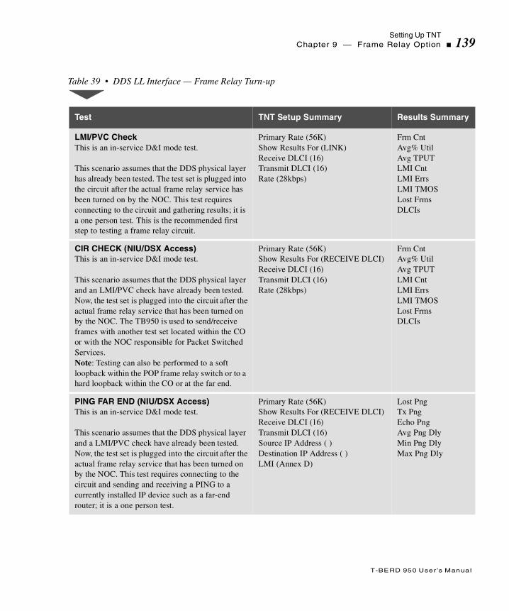
Setting Up TNTChapter 9 — Frame Relay Option 139
T-BERD 950 User ’s Manual
Table 39 • DDS LL Interface — Frame Relay Turn-up
Test TNT Setup Summary Results Summary
LMI/PVC CheckThis is an in-service D&I mode test.
This scenario assumes that the DDS physical layer has already been tested. The test set is plugged into the circuit after the actual frame relay service has been turned on by the NOC. This test requires connecting to the circuit and gathering results; it is a one person test. This is the recommended first step to testing a frame relay circuit.
Primary Rate (56K)Show Results For (LINK)Receive DLCI (16)Transmit DLCI (16)Rate (28kbps)
Frm CntAvg% UtilAvg TPUTLMI CntLMI ErrsLMI TMOSLost FrmsDLCIs
CIR CHECK (NIU/DSX Access)This is an in-service D&I mode test.
This scenario assumes that the DDS physical layer and an LMI/PVC check have already been tested. Now, the test set is plugged into the circuit after the actual frame relay service that has been turned on by the NOC. The TB950 is used to send/receive frames with another test set located within the CO or with the NOC responsible for Packet Switched Services. Note: Testing can also be performed to a soft loopback within the POP frame relay switch or to a hard loopback within the CO or at the far end.
Primary Rate (56K)Show Results For (RECEIVE DLCI)Receive DLCI (16)Transmit DLCI (16)Rate (28kbps)
Frm CntAvg% UtilAvg TPUTLMI CntLMI ErrsLMI TMOSLost FrmsDLCIs
PING FAR END (NIU/DSX Access)This is an in-service D&I mode test.
This scenario assumes that the DDS physical layer and a LMI/PVC check have already been tested. Now, the test set is plugged into the circuit after the actual frame relay service that has been turned on by the NOC. This test requires connecting to the circuit and sending and receiving a PING to a currently installed IP device such as a far-end router; it is a one person test.
Primary Rate (56K)Show Results For (RECEIVE DLCI)Receive DLCI (16)Transmit DLCI (16)Source IP Address ( )Destination IP Address ( )LMI (Annex D)
Lost PngTx PngEcho PngAvg Png DlyMin Png DlyMax Png Dly

Setting Up TNT140 Chapter 9 — Frame Relay Option
T-BERD 950 User ’s Manual
Performing Frame Relay Monitor Test
Table 39 lists the TNT setups for the T1 and DDS LL interfaces to perform a monitor test on Frame Relay. For descriptions of the test setup parameters, see “Setting Up Manual Frame Relay Test” on page 141. For descriptions of all results see “Test Results” on page 146.
The objective of performing a monitor test is to verify that the live frame relay traffic is transmitted without excessive congestion at the proper rate. Results such as FCS errors, frame rate, utilization, along with physical layer results can be viewed.
Table 40 • Frame Relay Monitor Tests
Test TNT Setup TNT Results
T1 Interface
In this scenario, you can connect to the monitor point and review the results.
Payload (FULL)Line Coding (AUTO)Show Results For (RECEIVE DLCI)Receive DLCI (16)Long Frame (4095)
(IF PAYLOAD = DDS)Channel (1)Rate (DS0A 56)
(IF PAYLOAD = nx64K or nx56K)Channels (pop up edit screen)
CRC ErrorsFrm ErrorsBPVsFrm CntLMI CntLMI ErrsDLCIsAvg% UtilAvg% Tput
DDS LL Interface
In this scenario, you can connect to the monitor point and review the results.
Primary Rate (56K)Show Results For (LINK)
Frm CntLMI CntLMI ErrsDLCIsAvg% UtilAvg TPUT

Setting Up Manual Frame Relay TestChapter 9 — Frame Relay Option 141
T-BERD 950 User ’s Manual
Setting Up Manual Frame Relay Test
This section provides descriptions of the Test setup parameters for the Interface and Test Type views for the Frame Relay option.
Setting Up the Interface View
The Interface Setup (see Figure 26) view lets you configure the mode, framing, rate, transmit clock for the selected interface. Depending on the interface you select, see “Setting Up the T1 Interface View” on page 62, or see “Setting Up the DDS LL Interface View” on page 120.
Figure 26 • Frame Relay Setup Interface View
Setting Up the Test Type View
The Test Type Setup view (see Figure 27) lets you configure the Frame Relay option. Press the SETUP key again to access the Test Type View.
Title Bar
SelectionArea
Mode: TERMINATEFraming: AUTOPayload: FULLLine Coding: B8ZSLine Rx In: TERMEquip Rx In: TERMTx Timing: INTERNALLoopcode: CSUAuto Respond: ONLine LBO: 0 dbYellow Alarm: OFF
Prompting
Softkeys
1:2 Interface T1-FRAME RELAY
FUNC Select Mode:
D&I MONITORTERMINATE
Area

Setting Up Manual Frame Relay Test142 Chapter 9 — Frame Relay Option
T-BERD 950 User ’s Manual
Figure 27 • Frame Relay Setup Test Type View
Show Results For — (all operating modes) Used to specify what results are shown (default is RECEIVE DLCI). Choices include:
RECEIVE DLCI — Selects results for a single Data Link Connection Identifier (DLCI).
LINK — Selects the aggregate total of all frame relay packets received over a single circuit.
Receive DLCI — (all operating modes) Enables entry of an individual DLCI (default is 16). The entry can be from 0 to 1023. Use the keypad or INCREASE VALUE or DECREASE VALUE softkeys to change the value.
Transmit DLCI — (TERMINATE or D&I modes only) Enables entry of an individual DLCI (default is 16). The entry can be from 0 to 1023. Use the keypad or INCREASE VALUE or DECREASE VALUE softkeys to change the value.
FECN Bit — (TERMINATE or D&I modes only) Enables entry of the FECN (Forward Explicit Congestion Notification) bit (default is 0). This is a binary entry field; the keypad keys 0 or 1 are used to enter the required value.
Title Bar
SelectionArea
Show Results For: LINKReceive DLCI: 16Transmit DLCI: 16FECN Bit: 0GECN Bit: 0DE Bit: 0C/R Bit: 0Load: FIXEDLoad Rate (kbps): 384Min Length: 256Max Length: 256Payload: SEQ TEST
Prompting
Softkeys
1:2 Test Type T1-BERT
PGDN
FUNC Select Mode:
LINKRECEIVEDLCI
Area
Setting Up Manual Frame Relay TestChapter 9 — Frame Relay Option 143
T-BERD 950 User ’s Manual
BECN Bit — (TERMINATE or D&I modes only) Enables entry of the BECN (Backward Explicit Congestion Notification) bit (default is 0). This is a binary entry field; the keypad keys 0 or 1 are used to enter the required value.
DE Bit — (TERMINATE or D&I modes only) Enables entry of the DE (Discard Eligibility) bit (default is 0). This is a binary entry field; the keypad keys 0 or 1 are used to enter the required value.
C/R Bit— (TERMINATE or D&I modes only) Enables entry of C/R (Command/Response Indication) bit (default is 0). This is a binary entry field; the keypad keys 0 or 1 are used to enter the required value.
Load — (TERMINATE or D&I modes only) Selects the frame payload type (default is OFF). Choices include the following: OFF, FIXED, BURST, or PING.
FIXED — When selected, the analyzer sends traffic at a fixed rate, the following choices include:
Rate — Enables entry of the load transmission rate from 1 to 8192 kbps (default is 1). Use the keypad or INCREASE VALUE or DECREASE VALUE softkeys to change the value.
Min Length — Enables entry of the minimum frame length. The length must be between 4 and 9999 (default is 256). Use the keypad or INCREASE VALUE or DECREASE VALUE softkeys to change the value.
Max Length — Enables entry of the maximum frame length. The length must be between 4 and 9999 (default is 256).Use the keypad or INCREASE VALUE or DECREASE VALUE softkeys to change the value.
PING — When selected, the analyzer transmits PING packets at a fixed rate of one per second. Enter the following parameters:
Source IP Address — Enables entry of the source IP address, format is xxx.xxx.xxx.xxx. Use the keypad to enter the address. (Leading zeros are deleted from the IP address when you exit from this field.)

Setting Up Manual Frame Relay Test144 Chapter 9 — Frame Relay Option
T-BERD 950 User ’s Manual
Destination IP Address — Enables entry of the destination IP address, format is xxx.xxx.xxx.xxx. Use the keypad to enter the address. NOTE: Leading zeros are deleted from the IP address when you exit this field.
BURST — When selected, the analyzer enables you to set the characteristics of bursty traffic to transmit. Choices include:
Transmit Time — Enables entry of the BURST transmit time in seconds from .5 to 99.9 (default is 0.5). Use the keypad or INCREASE VALUE or DECREASE VALUE softkeys to change the value.
Idle Time — Enables entry of the BURST idle time in seconds from .5 to 99.9 (default is 4.5). The keypad is used to enter the required time. Use the keypad or INCREASE VALUE or DECREASE VALUE softkeys to change the value.
Min Length — Enables entry of the minimum frame length. The length must be between 4 and 9999 (default is 256). Use the keypad or INCREASE VALUE or DECREASE VALUE softkeys to change the value.
Max Length — Enables entry of the maximum frame length. The length must be between 4 and 9999 (default is 256).Use the keypad or INCREASE VALUE or DECREASE VALUE softkeys to change the value.
Payload — (Burst and Fixed loads) Enables selection of the type of frame payload transmitted by the analyzer (default is SEQ TEST). Choices include:
SEQ TEST — Selects a test frame structure as shown in Figure 25 on page 133.
USER n — (Where n is the number of the USER data pattern i.e., 1 or 2.) Selects the test pattern as the test frame payload.
SEQ+USER n — (Where n is the number of the USER data pattern i.e., 1 or 2.) Selects the sequential test followed by the data from the LONG USER n test
Frame lengths of 15 octets, or less, prevents the detection of lost test frames.
Setting Up Manual Frame Relay TestChapter 9 — Frame Relay Option 145
T-BERD 950 User ’s Manual
pattern. The “FOX” payload of the test frame in Figure 25 on page 133, is replaced with the LONG USER n test pattern.
When Payload is set to USER n or SEQ+USER n, the following selection line appears:
USERn Data — (Where n is the number of the USER data pattern i.e., 1 or 2.) When selected, the Edit softkey appears, enabling you to edit the data pattern. Press the Edit softkey to access the USERn Data screen and the and the following softkeys:
Clear String — Clears the entire pattern.
Abort Changes — Aborts any changes made to the pattern.
Save & Exit — Saves the pattern and exits the User Pattern screen.
Press the MORE key to show these additional softkeys:
Cursor Home — Moves the cursor to the first digit of the pattern.
Cursor End — Moves the cursor to the last digit of the pattern.
Save & Exit — Saves the pattern and exits the User Pattern screen.
Press the MORE key to show these additional softkeys:
Next Page — Moves to the next page in the pattern.
Prev Page — Moves to the previous page in the pattern.
Save & Exit — Saves the pattern and exits the User Pattern screen.
Press the MORE key to show the original set of softkeys.
LMI — (All operating modes) Selects the Link Management Interface link management type. Choices include:
OFF — Selects no link management.
AUTO — Selects auto detection of LMI messages and determines the type of LMI being used on the link.
Test Results146 Chapter 9 — Frame Relay Option
T-BERD 950 User ’s Manual
LMI REV. 1 — Selects the frame relay consortium LMI link management.
T1.617-D — Selects ANSI T1-617 Annex D link management.
When LMI is set to AUTO, LMI REV.1, or T1.617-D, choices include:
Poll Time — Sets the time interval for heartbeat polling of the frame relay network. The interval can be set to any number from 5 up to 30 seconds (default is 10). Use the keypad or INCREASE VALUE or DECREASE VALUE softkeys to change the value.
Full Interval — Sets the Full Status Poll interval (measured in heartbeat poll cycles). The polling interval can be set to occur every 1 to 10 Poll cycles (default is 6). Use the keypad or INCREASE VALUE or DECREASE VALUE softkeys to change the value.
Long Frame — (all operating modes) Enables setting of the Long Frame threshold. The threshold can be set between 0 and 9999 octets (default is 4095). Use the keypad or INCREASE VALUE or DECREASE VALUE softkeys to change the value.
Test Results
Refer to “Results View” on page 33 for a detailed description of the Large Graphical Display Results view. A typical Frame Relay Test Type results view is shown in Figure 28 on page 147.
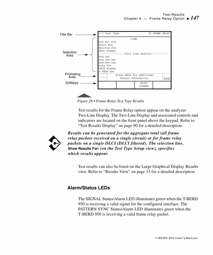
Test ResultsChapter 9 — Frame Relay Option 147
T-BERD 950 User ’s Manual
Figure 28 • Frame Relay Test Type Results
Test results for the Frame Relay option appear on the analyzer Two-Line Display. The Two-Line Display and associated controls and indicators are located on the front panel above the keypad. Refer to “Test Results Display” on page 90 for a detailed description.
Test results can also be listed on the Large Graphical Display Results view. Refer to “Results View” on page 33 for a detailed description.
Alarm/Status LEDs
The SIGNAL Status/Alarm LED illuminates green when the T-BERD 950 is receiving a valid signal for the configured interface. The PATTERN SYNC Status/Alarm LED illuminates green when the T-BERD 950 is receiving a valid frame relay packet.
Results can be generated for the aggregate total (all frame relay packets received on a single circuit) or for frame relay packets on a single DLCI (DLCI filtered). The selection line, Show Results For: (on the Test Type Setup view), specifies which results appear.
Title Bar
SelectionArea
LINEFCS Err FrmShort FrmAborted Frm%Err Frames-----------------Full Link Results------------Frm CntAvg Frm RatAvg Frm LenLong FrmFECN Frames% FECN Frm
Prompting
Softkeys
3:7 Test Type T1-FRAME RELAY
PGDN
Press HELP for Additional Result Information.
PRINTSCREEN
Area

Test Results148 Chapter 9 — Frame Relay Option
T-BERD 950 User ’s Manual
Summary Category Results
The Summary category automatically lists the main results that are out of specification. If all results are within specification for the LINE or EQUIPMENT receiver, the message All Results OK appears on the appropriate side of the Two-Line Display.
Interface Category Results
Interface category results are available for the physical layer interface selected. For T1 results see“Interface Category Results” on page 94 in T1 Test Results, Chapter 7. For DDS LL results see “Interface Category Results” on page 127 in the DDS LL option.
Test Type Category Results
The Test Type category results are described in Table 41.
A red illuminated LED indicates the Status/Alarm condition was present since the start of the current test.
There are no Time or Signal Category results for the Frame Relay option.
In the following table, the letter in brackets following the Result Name indicates whether the result applies to a single DLCI [F], the aggregate total of all frame relay packets received [A] or both [B].

Test ResultsChapter 9 — Frame Relay Option 149
T-BERD 950 User ’s Manual
Table 41 • Frame Relay Test Type Results
Result Name Description
FCS Err Frm [B] (FCS Errored Frames)
Counts the errored frames detected, includes FCS (Frame Check Sequence) errored frames only.
Short Frm [B](Short Frames)
Counts the short frames detected by the SCA (Serial Communications Adapter); the frame length is between 24 and 31 bits.
Aborted Frm [B] (Aborted Frames)
Counts the aborted frames detected (only available on the Two-Line Display when Show Results For is set to LINK; always available on the Large Graphical Display Results view).
%Err Frames [B] (% ErroredFrames)
Displays percent of errored Frame Relay frames detected calculated as (FCS errored frames + short frames + aborted frames) ÷ Physical frame count.
Frm Cnt [B] (Frame Count)
Counts the total number of valid Frame Relay frames detected.
Avg Frm Rat [B] (Average Frame Rate)
Counts Frame Relay frames received per second, since the start of the test.
Avg Frm Len [B] (Average Frame Length)
Calculates the average frame size as an integer (Frame Relay frame octets ÷ Frame Relay frame count).
Long Frm (Long Frames)
Counts the Frame Relay frames that exceed the user-specified length in octets.
FECN Frames [B] Counts the frames with the FECN (Forward Explicit Congestion Notification) bit set.
% FECN Frm [B] (% FECN Frames)
Displays percent of frames with the FECN bit set.
BECN Frames [B] Counts the frames with the BECN (Backward Explicit Congestion Notification) bit set.
% BECN Frm [B] (% BECN Frames)
Displays percent of frames with the BECN bit set.

Test Results150 Chapter 9 — Frame Relay Option
T-BERD 950 User ’s Manual
DE Frames [B] Counts the frames with the DE (Discard Eligibility) bit set.
% DE Frames [B] Displays percentage of frames with the DE bit set.
Lost Frm [F] (Lost Frames)
Counts TTC test frames that appear to have been lost by the network based on the test frame sequence number. This result is calculated on a single DLCI only. If the test frame length is less than 16 octets, lost frames are not counted.
% Lost Frm [F] (% Lost Frames)
Calculates percentage of TTC test frames that appear to have been lost by the network based on the test frame sequence number. This result is calculated on a single DLCI only.
LMI Type Indicates the type of LMI available on the frame relay circuit. In MONITOR mode, this result is an aggregate of the LINE and EQUIPMENT receivers, but appears for the LINE receiver only.
LMI Count Counts LMI messages received since the start of the test (an incrementing count indicates a “heartbeat”). In MONITOR mode, this result is an aggregate of the LINE and EQUIPMENT receivers, but appears for the LINE receiver only.
LMI Errs (LMI Errors)
Counts LMI STATUS ENQUIRY messages received that contained incorrect sequence numbers or an incorrect information element length. In MONITOR mode, this result is an aggregate of the LINE and EQUIPMENT receivers, but appears for the LINE receiver only.
LMI TMOS (LMI Timeouts)
Counts LMI STATUS ENQUIRY messages sent that yielded no response from the network before the next poll cycle. In MONITOR mode, this result is an aggregate of the LINE and EQUIPMENT receivers, but appears for the LINE receiver only.
Table 41 • Frame Relay Test Type Results (Continued)
Result Name Description

Test ResultsChapter 9 — Frame Relay Option 151
T-BERD 950 User ’s Manual
Performance Category Results
Performance category results are described in Table 42.
DLCIs Displays all configured DLCIs (Data Link Connection Identifiers) for a circuit, indicating the status of the DLCI as provided by the Full Status Poll. Deleted DLCIs apply to LMI Rev. 1 only. A status of “traffic” indicates that traffic was detected on the DLCI, but that DLCI was not listed in the Full Status Poll.NOTE: This result appears on the Large Graphical Display Results view.
Lost Pings Counts echo packets that were not replied to (includes out of order echo reply packets and corrupted echo reply packets). NOTE: This result is only available in TERMINATE mode.
Tx Pings (Transmitted Pings)
Counts echo packets/frames transmitted by the analyzer since the start of the test.NOTE: This result is only available in TERMINATE mode.
Echo Pings Counts echo replys transmitted by the analyzer since the start of the test.NOTE: This result is only available in TERMINATE mode.
In the following table, the letter in brackets following the Result Name indicates that the result applies to both [B], a single DLCI, and the aggregate total of all frame relay packets received.
Table 41 • Frame Relay Test Type Results (Continued)
Result Name Description

Test Results152 Chapter 9 — Frame Relay Option
T-BERD 950 User ’s Manual
Alarm Messages
Table 43 provides a list of results that appear on the Results Alarms view, along with a description of the alarm.
Table 42 • Frame Relay Performance Results
Result Description
Avg % Util [B](Average % Utilization)
Calculates average percentage of link utilization on the received channel since the start of the test. Calculated as (total Frame Relay octets in frames (excluding flags, including overhead) ÷ total octets (idle and frame data) received).
Max % Util [B] (Maximum %Utilization)
Calculates maximum percentage of link utilization on the received channel in any one second since the start of the test.
Avg Thruput [B](Average Throughput)
Calculates average received throughput since the start of the test, calculated as (total Frame Relay Frame bits (header + UDF + CRC) ÷ total seconds).
Max Thruput [B] (Maximum Throughput)
Calculates maximum received throughput, in bits per second, during any one second since the start of the test.
Avg Png Dly (Average PING Delay)
Calculates average round trip delay, measured in milliseconds, since the start of the test. NOTE: This result is only available in TERMINATE mode.
Max Png Dly (Maximum PING Delay)
Calculates maximum round trip delay, measured in milliseconds, since the start of the test.NOTE: This result is only available in TERMINATE mode.
Min Png Dly(Minimum PING Delay)
Calculates minimum round trip delay, measured in milliseconds, since the start of the test.NOTE: This result is only available in TERMINATE mode.

Test ResultsChapter 9 — Frame Relay Option 153
T-BERD 950 User ’s Manual
Table 43 • Frame Relay Alarms
Result Description
Inactive Tx DLCI Indicates the DLCI entered as the transmit address is not valid. There is not an active PVC associated with this DLCI
Rx Overflow Indicates when frames are dropped by the receiver.

Test Results154 Chapter 9 — Frame Relay Option
T-BERD 950 User ’s Manual

T
T-BERD 950 User ’s Manual
his section provides step-by-step instructions for the ISDN Primary Rate Interface (PRI) option for the T-BERD 950 and discusses the
following topics:
Option Description
TNT Setups
Manual Test Setups
Test Results
ISDN PRI Option
Option Description156 Chapter 9 — ISDN PRI Option
T-BERD 950 User ’s Manual
Option Description
The ISDN Primary Rate Interface (PRI) option, in conjunction with the Protocol Services Board option, enables the T-BER D950 Communications Analyzer to initiate, answer, or monitor ISDN PRI calls via the T1 interface. The option can be connected to ISDN circuits terminated by the following switches: AT&T 5ESS Ver. 9 (or later), NT DMS 100 Ver. BCS 38 (or later), and National ISDN-2 (NI-2) compliant switches.
In Terminate mode, the option has the capability to connect two calls simultaneously (two incoming, two outgoing, or one incoming and one outgoing). For example, it can call itself on a different B-channel. The interface can BER test up to two data calls or connect up to two voice calls. The call setup for these calls does not have to occur simultaneously. The call generation capability of the option enables you to specify the type of service to be connected (Voice, 56 kbps, 64 kbps, H0, H11, Nx64, or Nx56).
When the call setup acknowledge message is received for incoming or outgoing calls, it connects the speaker and microphone for that call. You can also change the connection of the call dynamically. A call can be dynamically connected to BERT, 1004 Hz tone, or Speaker/Microphone. If the ISDN PRI option is connected to two voice calls simultaneously, the first call is connected to the push-to-talk interface and a holding tone is placed on the second call. The unit can measure the loopback delay for each B-channel by connecting the calls to BERT.
ISDN Services
The T-BERD 950 supports testing of Non-Facility Associated Signaling (NFAS) and NFAS/D-channel Back Up (DCBU) operation. NFAS allows a single D-channel to control multiple T1 interfaces. Up to 20 T1 interfaces can be controlled via a single D-channel utilizing NFAS. Although this alleviates the customer from allocating a DS0 on every T1 for D-channel activity (i.e., this DS0 can now be used for
Option DescriptionChapter 9 — ISDN PRI Option 157
T-BERD 950 User ’s Manual
customer data), it introduces a higher level of risk. For example, if the primary T1 carrying the D-channel is taken out of service, the remaining associated T1s also must go out of service. This risk is minimized if NFAS service is ordered with back-up D-channel functionality. This functionality enables a standby D-channel to become activated if the IS D-channel is no longer reliable. The standby D-channel is dedicated to a DS0 on a secondary T1.
Operating Modes
The ISDN PRI option operates in one of two modes, Monitor mode or Terminate mode. The following paragraphs discuss each mode in detail.
Monitor Mode
In Monitor mode, the option monitors both directions of the ISDN D-channel. The mainframe is capable of collecting results on the D-channel simultaneously with the T1 interface specific results. Refer to “Test Results” on page 171 for a listing of the ISDN PRI option results.
Terminate Mode
In Terminate mode, the option emulates a TE (Terminal Equipment) device such as a PBX, a router, or an I-MUX. The analyzer originates all required frames for terminal emulation, Layer 2 startup, and basic call processing for the AT&T 5ESS, NT DMS 100, and NI-2 switches. When terminating a link, the results collected are for the received D-channel only.

Setting Up TNT158 Chapter 9 — ISDN PRI Option
T-BERD 950 User ’s Manual
Option Specifications
Refer to “T1 Specifications” on page 43 for ISDN PRI option specifications.
Setting Up TNT
This section describes the TNT test setups for the ISDN PRI option. A sample TNT Setup view is shown in Figure 29.
Figure 29 • ISDN PRI TNT Setup View
Performing T1 Interface ISDN PRI Turn-up
Table 44 lists the TNT test setup for performing T1 Interface ISDN PRI Turn-up in PBX Emulation. For descriptions of the test setup parameters, see “Setting Up Manual ISDN Test” on page 161. For descriptions of all results see“Test Results” on page 171.
Title Bar
SelectionArea
Framing: ESFBert Pattern: 2047Switch: NATIONALNumbering Plan: NATIONAL-------------------Call 1---------------------Call Type: VOICEProgram 1: 8442525Calling Number: 5551212-------------------Call 2--------------------Call Type: VOICEProgram 6: 8442525Calling Number: 5551212
Prompting
Softkeys
3:3 TNT PRI Single (23B+D)
FUNC Select Framing:
SF AUTO AUTO-RESF
Area
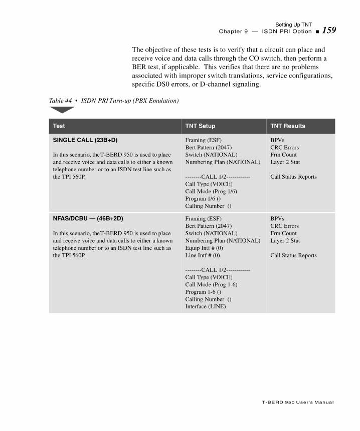
Setting Up TNTChapter 9 — ISDN PRI Option 159
T-BERD 950 User ’s Manual
The objective of these tests is to verify that a circuit can place and receive voice and data calls through the CO switch, then perform a BER test, if applicable. This verifies that there are no problems associated with improper switch translations, service configurations, specific DS0 errors, or D-channel signaling.
Table 44 • ISDN PRI Turn-up (PBX Emulation)
Test TNT Setup TNT Results
SINGLE CALL (23B+D)
In this scenario, the T-BERD 950 is used to place and receive voice and data calls to either a known telephone number or to an ISDN test line such as the TPI 560P.
Framing (ESF)Bert Pattern (2047)Switch (NATIONAL)Numbering Plan (NATIONAL)
--------CALL 1/2------------Call Type (VOICE)Call Mode (Prog 1/6)Program 1/6 ()Calling Number ()
BPVsCRC ErrorsFrm CountLayer 2 Stat
Call Status Reports
NFAS/DCBU — (46B+2D)
In this scenario, the T-BERD 950 is used to place and receive voice and data calls to either a known telephone number or to an ISDN test line such as the TPI 560P.
Framing (ESF)Bert Pattern (2047)Switch (NATIONAL)Numbering Plan (NATIONAL) Equip Intf # (0)Line Intf # (0)
--------CALL 1/2------------Call Type (VOICE)Call Mode (Prog 1-6)Program 1-6 ()Calling Number ()Interface (LINE)
BPVsCRC ErrorsFrm CountLayer 2 Stat
Call Status Reports

Setting Up TNT160 Chapter 9 — ISDN PRI Option
T-BERD 950 User ’s Manual
Performing ISDN PRI Monitor Test
Table 45 lists the TNT test setup for performing T1 Interface ISDN PRI Monitor Test. For descriptions of the test setup parameters, see “Setting Up Manual ISDN Test” on page 161. For descriptions of all results see “Test Results” on page 171.
The objective of this test is to passively verify the ability to place and receive calls between the PBX and the CO switch by looking at live calls, T1 results, and actual D-channel decodes. In addition, T1 physical layer results such as receive level, receive frequency, BPVs, and CRCs can be gathered.
MULTIPLE (47B+D)
In this scenario, the T-BERD 950 is used to place and receive voice and data calls to either a known telephone number or to an ISDN test line such as the TPI 560P.
Framing (ESF)Bert Pattern (2047)Switch (NATIONAL)Numbering Plan (NATIONAL) Equip Intf # (0)Line Intf # (0)
--------CALL 1/2------------Call Type (VOICE)Call Mode (Prog 1/6)Program 1/6 ()Calling Number ()Interface (LINE)
BPVsCRC ErrorsFrm CountLayer 2 Stat
Call Status Reports
Table 44 • ISDN PRI Turn-up (PBX Emulation) (Continued)
Test TNT Setup TNT Results

Setting Up Manual ISDN TestChapter 9 — ISDN PRI Option 161
T-BERD 950 User ’s Manual
Setting Up Manual ISDN Test
This section provides descriptions of the analyzer setup (see Figure 30) as it applies to the ISDN Primary Rate Interface (PRI) option.
Setting Up the Interface View
The Interface Setup view is used to configure the T1 interface, see “Setting Up the T1 Interface View” on page 62. The SCROLL and PAGE keys control this selection area.
Table 45 • ISDN PRI Monitor Test
Test TNT Setup TNT Results
MONITOR
In this scenario, you can connect to the monitor point and review the results.
Switch (NATIONAL)Line Interface # (0)D Channel # (24)
BPVsCRC errorsFram CountsLayer 2 Stat
CALL STATUS REPORTS

Setting Up Manual ISDN Test162 Chapter 9 — ISDN PRI Option
T-BERD 950 User ’s Manual
Figure 30 • ISDN PRI Setup Interface View
Setting Up the Test Type View
The ISDN PRI Test Type Setup view is used to configure the test to be performed (see Figure 31). The SCROLL and PAGE keys control this selection area.
Figure 31 • ISDN PRI Setup Test Type View
Title Bar
SelectionArea
Mode: TERMINATEFraming: AUTOLine Rx In: TERMEquip Rx In: TERMLine LBO: 0 dbEquip LBO: 0 DB
Prompting
Softkeys
1:2 Interface T1-ISDN PRI
FUNC Select Mode:
MONITORTERMINATE
Area
Title Bar
SelectionArea
Bert Pattern: 2047----------------------------------------------Switch: NATIONALNumbering Plan: NATIONALT1 Lines: SINGLELine Intf #: 0Line D Chan #: 24-------------------Call 1 --------------------Call Type: VOICEBearer Destination: SPEAKERChannel Select: ANY CHANNELCall Mode: PROGRAM 1
Prompting
Softkeys
2:2 Test Type T1-ISDN PRI
PGDN
FUNC
MORE
Select Bert Pattern:
2047 2047QRS DDS1511QRS
Area

Setting Up Manual ISDN TestChapter 9 — ISDN PRI Option 163
T-BERD 950 User ’s Manual
Bert Pattern — Selects the appropriate BERT pattern “Setting Up the T1 Test Type View” on page 80.
Switch — Enables entry of the switch type used on the ISDN link (default is NATIONAL). Choices include:
AT&T — Selects the AT&T 5ESS custom as the switch type.
NT — Selects the NT DMS 100 custom as the switch type.
NATIONAL — Selects the National ISDN-2 (NI-2) as the switch type.
Numbering Plan — Enables selection of the appropriate ISDN numbering plan for the desired circuit. The six numbering plan choices include:
UNKNOWN —Unknown number in numbering plan.
INTERNATIONAL —International number in ISDN numbering plan.
NATIONAL —National number in the ISDN numbering plan.
NETWORK —Network-specific number in private numbering plan.
LOCAL — Local directory number in ISDN numbering plan.
ABBREVIATED —Abbreviated number in private numbering plan.
T1 Lines — (TERMINATE mode only) Specifies the number of T1 interfaces to be tested (default is SINGLE). The choice is:
SINGLE — Specifies a single T1 line interface to be tested. The D-channel must be located on the LINE Tx/Rx pair.
Line Intf # — Use to set the primary T1 LINE interface number; any number between 0 and 19 can be selected (default is 0). Use either the keypad or the INCREASE VALUE or DECREASE VALUE softkeys to enter the value.
If the Line Interface # selected does not match the Line Interface # provided by the switch, the analyzer reconfigures to use the Line Interface # provided by the switch.
Setting Up Manual ISDN Test164 Chapter 9 — ISDN PRI Option
T-BERD 950 User ’s Manual
Line D Chan # — Use to set the D-channel number; any number between 1 and 24 can be selected (default is 24). Use either the keypad or the INCREASE VALUE or DECREASE VALUE softkeys to enter the value.
MULTIPLE — (TERMINATE mode only) Allows testing of NFAS service using multiple T1s controlled by a single D-channel. The D-channel must be located on the LINE Tx/Rx pair. When selected, in addition to Line Intf # and Line D Chan #, the following parameter choice is available:
Equip Intf # — (Multiple or NFAS/DCBU) Use to set the T1 EQUIPMENT interface number, any number between 0 and 19 can be selected (default is 1). Use either the keypad or the INCREASE VALUE or DECREASE VALUE softkeys to enter the value.
NFAS/DCBU — Enables testing of NFAS circuits optioned with DCBU. When selected, in addition to Line Intf #, Line D Chan #, and Equip Intf #, Choices include:
Equip D Chan # — Use to set the D channel number; any number between 1 and 24 can be selected (default is 24). Use either the keypad or the INCREASE VALUE or DECREASE VALUE softkeys to enter the value.
The following parameters must be set for each call you want to place.
Call Type — Selects the type of call to be originated by the option (default is VOICE). The choices include:
VOICE — Selects a voice type call.
The Equip Intf # should not be the same as the Line Intf #.
In DCBU, the primary D-channel must be located on the T1 connected to the LINE Interface, and the secondary D-channel must be located on the T1 connected to the EQUIPMENT Interface.

Setting Up Manual ISDN TestChapter 9 — ISDN PRI Option 165
T-BERD 950 User ’s Manual
56K — Selects an unrestricted circuit-switched data connection with 56 kbps CCITT I.463 rate adaptation.
64K UNRESTRICTED — Selects a clear channel, unrestricted, circuit-switched data connection with the full 64 kbps available for use, with no rate adaptation.
H0 — Selects an H0 384 kbps type data call.
H11 — Selects an H11 1536 kbps type data call (only available when T1 Lines is set to MULTIPLE and the call is placed on EQUIPMENT T1 Interface).
Nx64 — Selects contiguous/noncontiguous 64 kbps timeslot operation.
Nx56 — Selects contiguous/noncontiguous 56 kbps timeslot operation.
3.1K AUDIO — Selects a 3.1 kbps call type.
Bearer Destination — Selects the initial destination of the connected call (default is SPEAKER). Choices include:
SPEAKER — The call is initially connected to speaker/microphone for voice conversation.
BERT— The call is initially configured for BER testing.
Channel Select — Enables the user to specify a preferred channel to be used by the switch (default is ANY CHAN). Choices include:
ANY CHANNEL — When selected, the channel is assigned by the switch.
SPECIFIC — Enables you to specify the preferred channel to be used by the switch.
Depending on the settings you choose for Call Type and Channel Select the following choice may appear:
After the call is connected, use the Dynamic Payload softkeys to change the Bearer Destination, such as BERT or a speaker. (See “Using ISDN and Call Control Features” on page 167.)

Setting Up Manual ISDN Test166 Chapter 9 — ISDN PRI Option
T-BERD 950 User ’s Manual
Channel — Selects the channel to be used; any number between 1 and 24 can be entered (default is 1). Use either the keypad or the INCREASE VALUE or DECREASE VALUE softkeys to enter the value.
When Channel Select is set to SPECIFIC, the following choice appears:
Channel — Selects the channel to be used; any number between 1 and 24 can be entered (default is 1). Use either the keypad or the INCREASE VALUE or DECREASE VALUE softkeys to enter the value.
When Channel Select is set to SPECIFIC, and T1 Lines is set to MULTIPLE or NFAS/DCBU, choices include:
Interface — Selects which T1 interface the outgoing call is placed on. Choices include:
LINE — Selects the T1 LINE interface to place the outgoing call.
EQUIPMENT — Selects the T1 EQUIPMENT interface to place the outgoing call.
If the Call Type is set to H0 and Channel Select is set to SPECIFIC, the following parameter choice is available:
Channels — Use to set the channel group (default is 1-6. The channel group choices are 1-6, 7-12, 13-18, 19-24.
If the Call Type is set to VOICE, 3.1K AUDIO, 56K, 64K UNRESTRICTED, choices include:
Channel — Selects the channel to be used; any number between 1 and 24 can be entered (default is 1). Use either the keypad or the INCREASE VALUE or DECREASE VALUE softkeys to enter the value.
If the Call Type is set to Nx56 or Nx64, and Channel Select is set to Specific, choices include:
If the channel provided by the switch is different from the channel requested, the analyzer reconfigures to use the channel provided by the switch.

Setting Up Manual ISDN TestChapter 9 — ISDN PRI Option 167
T-BERD 950 User ’s Manual
Channel Map — Enables entry of the channel mapping (default is Channel 1 and Channel 2) to be used for the originated call using the Edit softkey. Press the Edit softkey to access the Edit Channel Map screen and the Select/Deselect, Clear All, Abort Changes, and Save & Exit softkeys.
Call Mode — Selects the appropriate Program Number (N). PROGRAM 1 through PROGRAM 5 (for Call 1), and PROGRAM 6 through PROGRAM 10 (for Call 2).
Program (N) — Enables entry of the number to be called, up to 18 digits (default is 8442525). You may program up to five numbers on PROGRAM 1 through PROGRAM 5 (for Call 1), and five numbers on PROGRAM 6 through PROGRAM 10 (for Call 2). Use the keypad (valid keys are 0 through 9) and softkeys (HOME, END, and CLEAR) to edit this field.
Calling Number — Enables entry of the Directory Number (DN) of the circuit being analyzed, up to 15 digits (default is 5551212). Use the keypad (valid keys are 0 through 9) and softkeys (HOME, END, and CLEAR) to edit this field.
Using ISDN and Call Control Features
The ISDN CONTROL softkey provides access to CALL 1 CONTROL, CALL 2 CONTROL, and SWITCH D-CHAN softkeys. When pressed, the Results Test Type view appears.
CALL 1 CONTROL or CALL 2 CONTROL provide the following choices:
DIAL CALL — Places the call.
DISC CALL — Disconnects the call in progress.
When Call Type is Nx56 or Nx64, you must select at least two (2) channels for Channel Map.

Setting Up Manual ISDN Test168 Chapter 9 — ISDN PRI Option
T-BERD 950 User ’s Manual
ANSWER — Answers the call if there is an incoming call present.
BERT — Connects the call for BERT testing
VOICE — Connects the call to the speaker/microphone.
TONE — Connects the call to a 1004 Hz tone.
SWITCH D-CHAN — (NFAS/DCBU mode only) This softkey initiates a D-channel backup switchover that switches the current IS D-channel to Standby, and the current Standby D-channel to IS.
Placing a Call
To place a call, choose from five possible program (or memory dial) numbers, then press the call DIAL CALL softkey. (See “Using ISDN and Call Control Features” on page 167 for Call Control information.)
Dynamic Payload Softkeys provide the ability to dynamically change the payload of the call when the call is connected.
You must have an In Service (IS) and a Standby D-channel to perform a DCBU switch over.
In addition to a manual switchover, the analyzer will automatically respond to the IS T1 interface being physically removed or logically removed by the network.
When physically removing the T1 jacks connected into the interface, it is recommended that you remove the T1 jacks from the analyzer, not the smart jack. Removing the connection at the smart jack could set up an automatic loopback within the smart jack that may cause problems.

Setting Up Manual ISDN TestChapter 9 — ISDN PRI Option 169
T-BERD 950 User ’s Manual
In general, the call emulation feature must simulate a normal call setup exchange. If the call setup exchange fails, extensive error reporting in the form of a call fail report is generated.
The T-BERD 950 is capable of transmitting DTMF tones if a call progresses or connects. The microphone disables briefly while the DTMF tones are transmitted. This feature allows you to enter digits such as phone extensions in response to an automated attendant.
Answering a Call
When an incoming call is detected, the T-BERD 950 a popup window on the current view will appear. This window gives you three choices: answer the call, ignore the call, and disconnect the call.
The action you choose will cause one of several results. Those actions and results are listed in Table 46.
Table 46 • ISDN PRI Incoming Call Activitie s
Action Result
Press Answer sofkey. The call connects to the speaker and microphone (voice). You can then choose to begin BER testing if it is a data call. After the call is connected, you can dynamically change the connection, data to voice or voice to data, using softkeys.
Press Disconnect softkey. The call is cleared.
Press Ignore softkey. The call remains in the alerting state until the far end cancels the call or you select the ISDN Control softkey, press the appropriate Call 1 or 2 softkey, then press the Answer softkey.
Setting Up Manual ISDN Test170 Chapter 9 — ISDN PRI Option
T-BERD 950 User ’s Manual
Interpreting D-Channel Display
This feature shows English translations of messages received and transmitted on the D-channel. This display provides complete Q.921 and/or Q.931 text-based information for all valid ISDN frames.
You may activate the D-channel Display (Figure 32 on page 171) by pressing the D-channel Display softkey. After pressing the softkey, the Large Graphical Display shows one message at a time. Messages are captured in the order they are transmitted and/or received.
The following softkeys allow you to navigate the messages as follows:
FIRST MESSAGE — Shows first message.
LAST MESSAGE — Shows last message.
PREVIOUS MESSAGE — Shows previous message.
NEXT MESSAGE — Shows next message.
The Print softkeys are as follows:
PRINT CURRENT — Prints the current message.
PRINT TO LAST — Prints all messages from the current to the last message.
PRINT ALL — Prints messages from the first to the last message.
Press the CLEAR STORAGE softkey to clear all capture messages. Press the EXIT softkey to exit the D-channel Display and return to the Home, Setup, Results, or System view.
For monitor mode operations, connect the LINE Tx/Rx pair towards the Network Termination (NT) equipment and the EQUIPMENT Tx/Rx pair towards the Customer Premise Equipment (CPE). This will provide proper information when determining the direction of the traffic on the D-channel. If the hookup is backwards, the direction of the traffic will be wrong.

Test ResultsChapter 9 — ISDN PRI Option 171
T-BERD 950 User ’s Manual
Status messages are shown on the Two-Line Display to indicate print activity and capture status. A message flashes when the capture buffer is full, indicating that frame capture is inactive. You must clear the capture buffer by pressing the CLEAR STORAGE softkey to resume frame capture. Capture storage will also be indicated as a percentage result (% full) on the Test Type Results view.
Figure 32 • ISDN PRI D-Channel Display
Test Results
Test results are shown on the T-BERD 950 analyzer screen on the Results I and II Two-Line Display. Other common results may also be available.
Capture storage is only maintained for the lifetime of the current test (for example, switching from PRI ISDN to BERT will clear the capture storage). Use the print softkeys to save relevant capture information before changing tests.
Title Bar
DisplayArea
LINE:NT->TE:C SAPI:000 TEI:000 00:10:22.00I Ns=018 Nr=019 P/F=0PD=08 Call Reference:012M 05 SETUPIE 04 BEARER CAPABILITYLen=03 80 Coding StandardCCITT Transfer CapabilitySpeech 90 Transfer Mode Circuit Transfer Rate 64 kbit/s A2 Layer 1 Protocolu-lawIE 18 CHANNEL ID Len=03 A9 Indicated ChannelExclusive
Prompting
Softkeys
D CHANNEL DISPLAY 000 OF 000
FUNC
MORE
NEXTMESSAGE
PREVMESSAGE
Area
Test Results172 Chapter 9 — ISDN PRI Option
T-BERD 950 User ’s Manual
Test results for the ISDN PRI option are shown on the analyzer Two-Line Display. The Two-Line Display and associated controls and indicators are located on the front panel above the keypad. Refer to “T1 Test Results” on page 89 for a detailed description of the Results Display.
Test results can also appear on the Results view (refer to “Results View” on page 33).
Typical ISDN PRI Test Type results are Summary, Interface, and Test Type Category results. Each type is described in the following sections.
Summary Category Results
The Summary category automatically shows key results that are out of specification. If all results are within specification for the LINE or EQUIPMENT receiver, the message All Results OK appears on the appropriate side of the Two-Line Display.
Interface Category Results
Interface results are available for the T1 physical layer interface selected. See ‘Interface Category Results’ on page 94.
Test Type Category Results
Test Type category results are described in Table 47. Unless stated otherwise, all results are available in MONITOR and TERMINATE modes. BERT results are listed with the Test Type results. For descriptions of BERT results see “T1 Test Results” on page 92.

Test ResultsChapter 9 — ISDN PRI Option 173
T-BERD 950 User ’s Manual
Table 47 • ISDN PRI Test Type Result s
Result Name Description
DCBU Stat Displays the status of the D-channel in relation to DCBU operation. A DCBU switchover can be performed when both D channels are in the Ready status.Ready — Indicates that the D-channel is in the proper state for DCBU operation (IS or Standby).Not Ready — Indicates that the D-channel is not ready and is in the Out of Service state.Not In Serv — Indicates that the D-channel is attempting to become the IS D-channel. The D-channel may be in this state during normal DCBU initialization and switchover operations and should eventually transition to Ready status indicating normal operation.Not Standby — Indicates that the D-channel should be in Standby state. This status occurs during normal DCBU initialization and switchover operations and should eventually transition to Ready status indicating normal operation.
D-Chan Stat Displays state of the D-channel for DCBU operation. In Service — The indicated D-channel is the IS D-channel and is operating normally.Standby — The indicated D-channel is the Standby D-channel and is operating normally.Out of Service — The indicated D-channel is currently Out of Service, indicating problems in the operation of the D-channel.Wait — The indicated D-channel is waiting to become the IS D-channel.Maint Busy — The indicated D-channel declines establishment attempts while the other D-channel is becoming IS (Wait State).
Layer2 Stat Displays Layer 2 Status Values include: TEI Not Assigned, Awaiting TEI, Link Not Established, Awaiting Establishment, Link Established, Timer Recovery, Awaiting Release, TEI Denied, Link Unknown. If the status is Link Not Established, a flashing two-line message appears on RESULTS I and or RESULTS II to indicate that calls cannot be placed.
Frm Count Counts the valid ISDN frames received.
Err Frm Counts the errored frames received with at least one of the following conditions: undefined control field, U frame with an improper length, and I frame with a length exceeding limit.
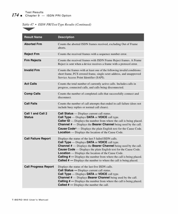
Test Results174 Chapter 9 — ISDN PRI Option
T-BERD 950 User ’s Manual
Aborted Frm Counts the aborted ISDN frames received, excluding Out of Frame aborts.
Reject Frm Counts the received frames with a sequence number error.
Frm Rejects Counts the received frames with ISDN Frame Reject frames. A Frame Reject is sent when a device receives a frame with a protocol error.
Invalid Frm Counts the frames with at least one of the following invalid conditions: short frame, FCS errored frame, single octet address, and unapproved Service Access Point Identifier (SAPI).
Act Calls Counts the total number of currently active calls. Includes calls in progress, connected calls, and calls being disconnected.
Comp Calls Counts the number of completed calls that successfully connect and disconnect.
Call Fails Counts the number of call attempts that ended in call failure (does not include busy replies or normal call clears).
Call 1 and Call 2 Status
Call Status — Displays current call status.Call Type — Displays DATA or VOICE call type.Caller ID — Displays the number from where the call is being placed.Channel # — Displays the Bearer Channel being used by the call.
Cause Codea — Displays the plain English text for the Cause Code.Location — Displays the location of the Cause Code.
Call Failure Report Displays the status of the last 5 failed ISDN calls.Call Type — Displays DATA or VOICE call type.Channel # — Displays the Bearer Channel being used by the call.Cause Code — Displays the plain English text for the Cause Code.Location — Displays the location of the Cause Code.Calling # — Displays the number from where the call is being placed.Called # — Displays the number to where the call is being placed.
Call Progress Report Displays the status of the last five ISDN calls. Call Status — Displays current call status.Call Type — Displays DATA or VOICE call type.Channel # — Displays Bearer Channel being used by the call.Calling # — Displays the number from where the call is being placed.Called # — Displays the number the call.
Table 47 • ISDN PRI Test Type Results (Continued)
Result Name Description

Test ResultsChapter 9 — ISDN PRI Option 175
T-BERD 950 User ’s Manual
Sample Test Type Results
D-channel Back Up Results are shown in Figure 33. Call Status Results are shown in Figure 34.
Figure 33 • ISDN PRI D-channel Backup Results
% FULL Displays the current amount of storage used (% full) for D-channel message capture.
Messages Displays the current number of messages available to the D-channel display (see “Interpreting D-Channel Display” on page 170).
a. The analyzer interprets the Cause code for you; however, a complete list of Cause Codes can be found in Table 48, on page 176,
Table 47 • ISDN PRI Test Type Results (Continued)
Result Name Description
Title Bar
DisplayArea
LINE EQUIPDCBU Stat Ready ReadyD-Chan Stat In Service StandbyLayer2 Stat Link Estab Link EstabFrm Count 30 102Err Frm 0 0Aborted Frm 0 0Reject Frm 0 0Frm Rejects 0 0Invalid Frm 0 0Call Fails 0
Prompting
Softkeys
3:7 Test Type T1-ISDN PRI
PGUP
PGDN
FUNC Press HELP for Additional Result Information.
D CHANNELDISPLAY
PRINTSCREEN
ISDNCONTROL
Area

Test Results176 Chapter 9 — ISDN PRI Option
T-BERD 950 User ’s Manual
Figure 34 • ISDN PRI Call Status Results
ISDN Q.931 Cause Codes
Table 48 provides English translations of Q.931 messages received and transmitted on the D-channel.
Table 48 • ISDN PRI Results Reports Cause Code s
Class Value No. Cause Code
— Q.931 Cause Codes (1988) —
000 00010010001101100111
12367
Unassigned number.No route to specified transit network.No route to destination.Channel unacceptable.Call awarded and being delivered in an established channel.
Title Bar
DisplayArea
---------- Call 1 Status -----------Call Status: Call ConnectedCall Type: SpeechCaller ID:Line #: 0Channel #: 1Cause Code: No CauseLocation: User---------- Call 2 Status -----------Call Status: IdleCall Type: SpeechCaller ID:
Prompting
Softkeys
3:7 Test Type T1-ISDN PRI
PGUP
PGDN
FUNC Press HELP for Additional Result Information.
D CHANNELDISPLAY
PRINTSCREEN
ISDNCONTROL
Area

Test ResultsChapter 9 — ISDN PRI Option 177
T-BERD 950 User ’s Manual
001 000000010010011101010110101010111100110111101111
161718192122262728293031
Normal call clearing.User busy.No user responding.No answer from user (user alerted).Call rejected.Number changed.Non-selected user clearing.Destination out of order.Invalid number format.Facility rejected.Response to STATUS INQUIRY.Normal, unspecified.
010 0001011010011010101111001111
34384142434447
No circuit/channel available.Network out of order.Temporary failure.Switching equipment congestion.Access information discarded.Requested circuit/channel not available.Resources unavailable, unspecified.
011 000100100110100110101111
495054575863
Quality of service unavailable.Requested facility not subscribed.
Incoming calls barreda
Bearer capability not authorized.Bearer capability not presently available.Service or option not available, unspecified.
100 0001001001010110
1111
65666970
79
Bearer capability not implemented.Change type not implemented.Requested facility not implemented.Only restricted digital information bearer capability is available.Service or option not implemented, unspecified.
Table 48 • ISDN PRI Results Reports Cause Codes (Continued)
Class Value No. Cause Code

Test Results178 Chapter 9 — ISDN PRI Option
T-BERD 950 User ’s Manual
101 000100100011010001010110100010111111
818283848586889195
Invalid call reference value.Identified channel does not exist.A suspended call exists, but this call identity does not.Call identity in use.No call suspended.Call having the requested call identity has been cleared.Incompatible destination.Invalid transit network selection.Invalid message, unspecified.
110 000000010010
00110100010101101111
969798
99100101102111
Mandatory information element is missing.Message type nonexistent or not implemented.Message not compatible with call state or message type nonexistent or not implemented.Information element nonexistent or not implemented.Invalid information element contents.Message not compatible with call state.Recovery on timer expired.Protocol error, unspecified.
111 1111 127 Interworking, unspecified.
— National-specific Cause Codes Defined in TA-NWT-001268 —
000 01001000100110101011
4891011
Vacant code.Prefix 0 dialed in error.Prefix 1 dialed in error.Prefix 1 not dialed.Excessive digits received, call is proceeding.
110 0101 101 Protocol error, threshold exceeded.
a. This code was defined in the 1984 revision of Q.931, but omitted from the 1988 revision. The DMS 100 switch supports this code.
Table 48 • ISDN PRI Results Reports Cause Codes (Continued)
Class Value No. Cause Code

T
T-BERD 950 User ’s Manual
his section provides step-by-step instructions for using the Signaling option and discusses the following topics:
Option Description
TNT Test Setups
Manual Signaling Test Setups
Test Results
Signaling Option

Option Description180 Chapter 9 — Signaling Option
T-BERD 950 User ’s Manual
Option Description
The Signaling option enables the T-BERD 950 Communications Analyzer to perform signaling tests and to test against different trunk types. In addition, this option enables the analyzer to establish a voice or data call so that the microphone, PCM TIMS option (if installed), or BERT source/sync can transmit/receive tones, voice, or data without dropping the call.
The external interface to the Signaling option is the T1 interface (both LINE and EQUIPMENT connectors are used). The PCM in-band robbed bit signaling works with channel data dropped from or inserted in a T1 line.
Operating Modes
The Signaling option operates in one of the following T1 operating modes: Terminate, Drop & Insert, or Monitor mode. The following paragraphs provide a brief discussion of each mode.
Terminate Mode
In Terminate mode both sides of a T1 path are separated; the input signal is terminated at the receive side; and a totally independent signal is generated for the output.
Drop & Insert Mode
The Drop & Insert mode enables the analyzer to access specific channels from the T1 line while leaving the other channels unaffected.
Option DescriptionChapter 9 — Signaling Option 181
T-BERD 950 User ’s Manual
Monitor Mode
Monitor mode enables you to monitor originating sequences (originating supervision events and digits) transmitted on one line and monitor terminating response sequences (terminating supervision events) on the other line. While in Monitor mode, data cannot be inserted on a T1 line. This test is used to monitor two in-service switches that are communicating with each other.
You can select the trunk type of the lines monitored and the direction to the station or central office, thus enabling the analyzer to recognize the originating line automatically. The speaker is enabled at all times during the test so you can listen to the channel data being dropped. The speaker allows you to listen to one or both directions of the full duplex DS0 channel being monitored. The signaling scan feature allows the unit to cycle through the channels sequentially and automatically selects the first channel on which an off-hook signaling event is detected.
Signaling Sequence Types
The following paragraphs describe the signaling sequence types available for use with the Signaling option.
Call Origination Signaling
Call Origination enables the analyzer to transmit complex sequences of supervision events and digits (pre-defined sequences and manual dialing is supported) to switches/PBXs to test the ability of switching equipment to receive incoming calls.
TERMINATE or D&I must be selected on the Setup Interface view (for T1) in order to run this test.
Option Description182 Chapter 9 — Signaling Option
T-BERD 950 User ’s Manual
Pre-defined Signaling Sequences
Pre-defined signaling sequences enable you to program complex signaling sequences that emulate switch-to-switch or PBX-to-switch communications. Both originating and terminating supervision events, as well as digits, can be programmed in a sequence. The originating supervision events and digits are transmitted by the test set, while terminating supervision events are received by the test set and provide handshaking with the digit-receiving device. Up to 64 digits/supervision events can be programmed into a sequence. Digits are transmitted as programmed in the sequence. The Dial Tone is a terminating supervision event and can also be programmed into a sequence. After the pre-programmed sequence is selected, you can initiate transmission.
Manual Dialing Signaling
Manual dialing enables you to originate a call just as if a regular telephone was being used. The following digit types are available for use in manual dialing: Dial Pulse (DP), Multifrequency (MF), and Dual Tone Multifrequency (DTMF). You must press the On Hook and Off Hook softkeys (located on the Signaling Test Type Results Test Type view) at the appropriate time to complete a call. The speaker is enabled at all times during the test so that you can listen to the channel data being dropped and inserted.
Call Termination Signaling
Call Termination enables the analyzer to emulate a switch/PBX in order to receive a signaling sequence from a far end PBX/switch.
TERMINATE or D&I must be selected on the Setup Interface view (for T1) in order to run this test.

Option DescriptionChapter 9 — Signaling Option 183
T-BERD 950 User ’s Manual
In Call Termination, a pre-defined sequence of originating supervision events, digits, and terminating supervision events is required. The originating supervision events and digits are received by the analyzer, while the terminating supervision events are transmitted by the analyzer and provide the handshaking with the digit-sending device. Up to 64 digits/supervision events can be programmed into a sequence. These sequences are the same sequences used for call origination. See ‘Call Origination Signaling’ on page 181. The Dial Tone is considered to be a terminating supervision event, which can also be programmed into a sequence.
Signaling Trunk Types
The Trunk Type signaling is used to define the On Hook and Off Hook signaling status of the A, B, C, and D signaling bits. All trunk types are available regardless of the T1 Interface framing mode (e.g., SLC trunk types can be selected without SLC framing). The available trunk types are Standard (E&M), Ground Start, Loop Start, and User Defined. The following paragraphs describe each trunk type. An ‘X’ indicates a “don’t care” condition, and a ‘/’ indicates switching.
Standard (E&M) Signaling
The standard E&M signaling is used on trunks between switches in the public switched telephone network (PSTN). The E&M signaling is listed in Table 49.

Option Description184 Chapter 9 — Signaling Option
T-BERD 950 User ’s Manual
Ground Start Signaling
Ground Start trunk type circuits provide additional supervision to prevent outgoing calls commencing on circuits with incoming calls present. The signaling for the various types of Ground Start trunks [Foreign Exchange Station (FXS), Foreign Exchange Office (FXO), Subscriber Line Carrier (SLC) Station, and SLC Office] is as follows:
Ground Start FXS Signaling
The Ground Start FXS signaling is described in Table 50.
Table 49 • Standard E&M Signaling
Direction Trunk Status Signaling Bits
TRANSMIT:On Hook A=0 B=0 (C=0 D=0)
Off Hook A=1 B=1 (C=1 D=1)
RECEIVE:On Hook A=0 B=X (C=0 D=X)
Off Hook A=1 B=X (C=1 D=X)
Table 50 • Ground Start FXS Signaling
Direction Trunk Status Signaling Bits
TRANSMIT On Hook A=0 B=1 (C=0 D=1)
Ground A=0 B=0 (C=0 D=0) Ground on Ring
Off Hook A=1 B=1 (C=1 D=1) Loop closed after the far end FXO sends A=0 (Ground on Tip)

Option DescriptionChapter 9 — Signaling Option 185
T-BERD 950 User ’s Manual
Ground Start FXO Signaling
The Ground Start FXO signaling is described in Table 51.
Ground Start SLC Station Signaling
Ground Start SLC Station signaling is described in Table 52.
RECEIVE On Hook A=1 B=X (C=1D=X) No Tip Ground
Off Hook A=0 B=1 (C=0 D=1) Tip Ground
Ringing A=X B=0 (C=X D=0)
Table 51 • Ground Start FXO Signaling
Direction Trunk Status Signaling Bits
TRANSMIT
On Hook A=1 B=1 (C=1 D=1) No Ground on Tip
Off Hook A=0 B=1 (C=0 D=1) Ground on Tip
Ringing A=0 B=0 (C=X D=0)
RECEIVE
On Hook A=0 B=1 (C=0 D=1) Loop Idle
Ground A=0 B=0 (C=0 D=0) Ground on Ring
Off Hook A=1 B=1 (C=1 D=1) Loop closed
Table 50 • Ground Start FXS Signaling (Continued)
Direction Trunk Status Signaling Bits

Option Description186 Chapter 9 — Signaling Option
T-BERD 950 User ’s Manual
Ground Start SLC Office Signaling
Ground Start SLC Office signaling is described in Table 53.
Table 52 • Ground Start SLC Station Signaling
Direction Trunk Status Signaling Bits
TRANSMIT
On Hook A=0 B=0
Ground A=0 B=1 Ground on Ring
Off Hook A=1 B=0 Loop closed after the far end FXO sends B=0 (Ground on Tip)
RECEIVE
On Hook A=0 B=0 No Tip Ground
Off Hook A=0 B=0/1 Tip Ground
Ringing A=1 B=1/0
Table 53 • Ground Start SLC Office Signaling
Direction Trunk Status Signaling Bits
TRANSMIT
On Hook A=0 B=0 No Ground on Tip
Off Hook A=0 B=0/1
Ringing A=1 B=1/0
RECEIVE
On Hook A=0 B=0 Loop Idle
Ground A=0 B=1 Ground on Ring
Off Hook A=1 B=1 Loop closed

Option DescriptionChapter 9 — Signaling Option 187
T-BERD 950 User ’s Manual
Loop Start Trunk Type Signaling
The Loop Start trunk type circuits emulate standard signaling between a telephone and a switch. The signaling for the various types of Loop Start trunks (FXS, FXO, SLC Station, and SLC Office) is as follows.
Loop Start FXS Signaling
Loop Start FXS signaling is described in Table 54.
Loop Start FXO Signaling
Loop Start FXO signaling is described in Table 55.
Table 54 • Loop Start FXS Signaling
Direction Trunk Status Signaling Bits
TRANSMIT:On Hook A=0 B=1 (C=0 D=1)
Off Hook A=1 B=1 (C=1 D=1) Loop closed
RECEIVE:
On Hook A=0 B=1 (C=0 D=1)
Off Hook A=0 B=1 (C=0 D=1)
Ringing A=X B=0 (C=X D=0)

Option Description188 Chapter 9 — Signaling Option
T-BERD 950 User ’s Manual
Loop Start SLC Station Signaling
Loop Start SLC Office signaling is described in Table 56.
Loop Start SLC Office Signaling
Loop Start SLC Office signaling is described in Table 57.
Table 55 • Loop Start FXO Signaling
Direction Trunk Status Signaling Bits
TRANSMIT:
On Hook A=0 B=1 (C=0 D=1)
Off Hook A=0 B=1 (C=0 D=1)
Ringing A=0 B=0 (C=0 D=0)
RECEIVE:On Hook A=0 B=X (C=0 D=X) Loop Idle
Off Hook A=1 B=X (C=1 D=X) Loop closed
Table 56 • Loop Start SLC Station Signaling
Direction Trunk Status Signaling Bits
TRANSMITOn Hook A=0 B=0
Off Hook A=1 B=0 Loop closed
RECEIVE
On Hook A=1 B=1 Idle
Off Hook A=1 B=1 Idle
Ringing A=1 B=1/0

Option DescriptionChapter 9 — Signaling Option 189
T-BERD 950 User ’s Manual
User-Defined Trunk Type Signaling
The user-defined trunk type signaling enables you to specify your own signaling states for On Hook and Off Hook signaling status. Transmit states can vary from the receive states. The signaling bit settings are 0, 1, and “don’t care.” The “don’t care” is treated as a 1 when transmitted.
Programmable Signaling Elements
A pre-defined signaling sequence can contain both originating and terminating supervision events as well as digits. Up to 64 supervision events/digits can be pre-programmed into a sequence. The analyzer can store five origination sequences and five termination sequences. The digit type and associated symbols are detailed in Table 58 and the
Table 57 • Loop Start SLC Office Signaling
Direction Trunk Status Signaling Bits
TRANSMIT
On Hook A=1 B=1 Idle
Off Hook A=1 B=1 Idle
Ringing A=1 B=1/0
RECEIVEOn Hook A=0 B=0 Loop Idle
Off Hook A=1 B=0 Loop closed
The On Hook and Off Hook signaling bits are duplicated for both the transmit and receive sides.

Option Description190 Chapter 9 — Signaling Option
T-BERD 950 User ’s Manual
supervision events and associated symbols are detailed in Table 59. When an element in a sequence does not match with the test, that element is ignored by the test.
Table 58 • Digit Type Symbols for User-Defined Signalin g
Digit Type Digit Symbol
DP 0 through 9
DTMF 0 through 9, A, B, C, D, #, *
MF 0 through 9, KP, ST, STP, ST2P, ST3P
Table 59 • Supervision Event Symbols for User-Defined Signalin g
Supervision Event Supervision Event Symbol
Originating On Hook O
Originating Off Hook H
Originating Ring R
Ground on Ring G
Originating Pause P
Terminating On Hook o
Terminating Off Hook h
Terminating Wink w
Terminating Delay Dial d
Terminating Dial Tone t
For Ground Start Trunk selections, the Off Hook sequence is automatically initiated.

Option DescriptionChapter 9 — Signaling Option 191
T-BERD 950 User ’s Manual
Option Specifications
The Signaling option signaling element specifications are provided in Table 60.
Table 60 • Signaling Option Specificatio n s
Item Specification
Transmit Signaling Element Tone Digit Duration:Tone Digit Inter-digit Time:Pulse Digit Pulse Per Second:Pulse Digit %Break:Pulse Digit Inter-digit Time:
Consecutive Originating Event Delaya:Consecutive Terminating Event Delay:Tone Digit Level:Wink Delay:Wink Duration:Delay Dial Delay:Delay Dial Duration:Origination Off Hook:
a. In an H O sequence, there is no terminating event with which to handshake; so the event On Hook is sent 60 msec after the Off Hook event.
70 msec70 msec1060800 msec60 msec60 msec-7 dBm200 msec150 msec200 msec150 msec> 600 msec
Receive Signaling Element Wink Delay:Wink Duration:Delay Dial Delay:Delay Dial Duration:Off Hook Delay:Off Hook Duration:Pulse Digit Pulse Per Second:Pulse Digit %Break:Pulse Digit Inter-digit Time:Tone Digit Frequency:Tone Digit Level:MF Twist:DTMF Twist Low Freq relative to High Freq:Tone Digit Duration:Tone Digit Inter-digit Time:Disconnect Time:
0 to 16 sec70 msec to 600 msec0 to 16 sec70 msec to 16 sec0 to 60 sec> 600 msec7 to 21 pps40 to 68%> 300 msec< ± 2.5%> -30 dB< ± 6 dB-4 dB to 8 dB> 30 msec> 25 msec5 sec
Setting Up TNT192 Chapter 9 — Signaling Option
T-BERD 950 User ’s Manual
Option Messages
The message Sequence Fail flashes on the Two-Line Display when a pre-defined Call Origination or Call Termination sequence is not satisfied by the signaling events that occurred on the line. This message also appears when a signaling event delays more than 60 seconds.
Setting Up TNT
This section describes the TNT test setups to perform a T1 Interface PBX/Switch Turn-up.
Performing T1 Interface PBX/Switch Turn-up
Table 61 lists the TNT test setups for PBX/Switch Turn-up. For descriptions of the test setup parameters, see “Setting Up the T1 Interface View” on page 62. For descriptions of all results see “T1 Test Results” on page 92.
The objective of this test is to verify that the circuit can be used to place or receive a voice call. When the test is performed at the NIU access point, the call is tested through the CO switch while at a T1 access point. When the test is performed at the DSX access point, the call is tested while at a T1 access point. This will verify that there are no problems associated with improper timing, improper number of digits, wrong digit type, and/or overall switch translations.

Setting Up TNTChapter 9 — Signaling Option 193
T-BERD 950 User ’s Manual
Performing T1 Monitor Tests
The purpose of the Voice Monitor test verifies the ability to place and receive calls between the PBX and the CO switch by looking at the completion of live calls. Table 62 provides detailed test scenarios, TNT setup items, and test results.
Table 61 • T1 Interface PBX/Switch Turn-up
Test TNT Setup Results Summary
Voice Call — NIU
In this scenario, the technician is usually located at the customer premise at the Network Interface Unit (NIU) or a HTU-R. The T-BERD 950 is emulating a PBX or CO Switch. The test is performed after the T1 physical layer has been tested and the actual voice service has been activated by the switch technician. Normally, a call is placed to any known telephone number.
Framing (ESF)Channel (1)Line Coding (B8ZS)Tx Timing (RECOVERED)Drop to Speaker (BOTH)Trunk (E&M)Emulate (FXS)Seq Type (DIAL)Dial Seq (MANUAL)
BPVsCRC ErrorsT1 Rcv FrqT1 Rcv Lvl (dB)Signaling Events
Voice Call — DSX
In this scenario, the technician is located within a central office at a DSX patch panel. The T-BERD 950 is emulating a PBX or CO Switch. The test is performed after the T1 physical layer has been tested and the actual voice service has been activated by the switch technician. Normally, a call is placed to any known telephone number.
Framing (ESF)Channel (1)Line Coding (B8ZS)Insert Side (LINE TX)Drop to Speaker (BOTH)Trunk (E&M)Seq Type (DIAL)Dial Seq (MANUAL)Emulate (FXS)
BPVsCRC ErrorsT1 Rcv FrqT1 Rcv LvlSignaling Events
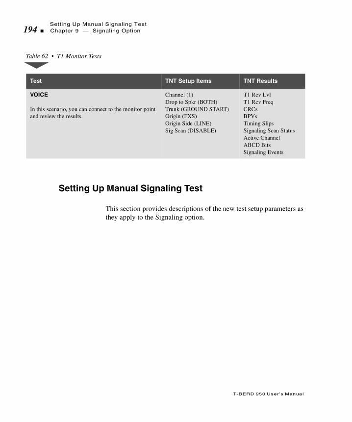
Setting Up Manual Signaling Test194 Chapter 9 — Signaling Option
T-BERD 950 User ’s Manual
Setting Up Manual Signaling Test
This section provides descriptions of the new test setup parameters as they apply to the Signaling option.
Table 62 • T1 Monitor Tests
Test TNT Setup Items TNT Results
VOICE
In this scenario, you can connect to the monitor point and review the results.
Channel (1)Drop to Spkr (BOTH)Trunk (GROUND START)Origin (FXS)Origin Side (LINE)Sig Scan (DISABLE)
T1 Rcv LvlT1 Rcv FreqCRCsBPVsTiming SlipsSignaling Scan StatusActive ChannelABCD BitsSignaling Events
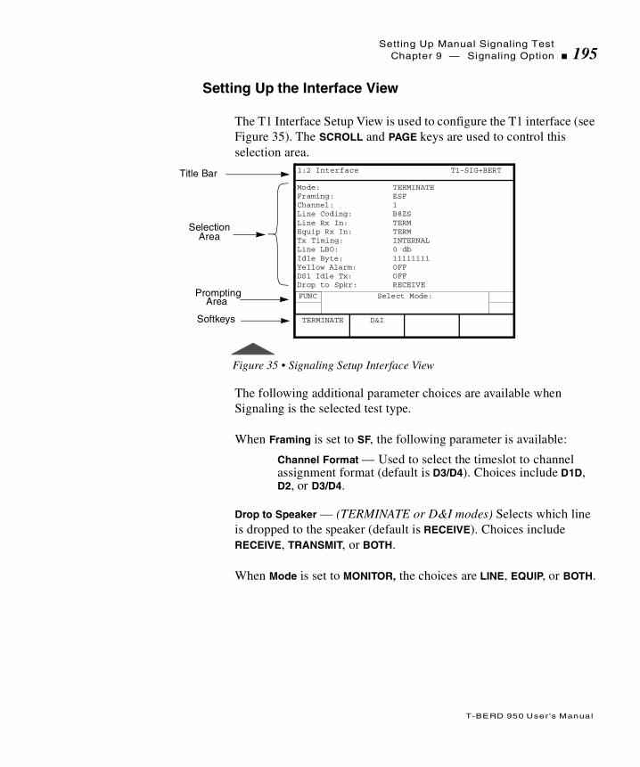
Setting Up Manual Signaling TestChapter 9 — Signaling Option 195
T-BERD 950 User ’s Manual
Setting Up the Interface View
The T1 Interface Setup View is used to configure the T1 interface (see Figure 35). The SCROLL and PAGE keys are used to control this selection area.
Figure 35 • Signaling Setup Interface View
The following additional parameter choices are available when Signaling is the selected test type.
When Framing is set to SF, the following parameter is available:
Channel Format — Used to select the timeslot to channel assignment format (default is D3/D4). Choices include D1D, D2, or D3/D4.
Drop to Speaker — (TERMINATE or D&I modes) Selects which line is dropped to the speaker (default is RECEIVE). Choices include RECEIVE, TRANSMIT, or BOTH.
When Mode is set to MONITOR, the choices are LINE, EQUIP, or BOTH.
Title Bar
SelectionArea
Mode: TERMINATEFraming: ESFChannel: 1Line Coding: B8ZSLine Rx In: TERMEquip Rx In: TERMTx Timing: INTERNALLine LBO: 0 dbIdle Byte: 11111111Yellow Alarm: OFFDS1 Idle Tx: OFFDrop to Spkr: RECEIVE
Prompting
Softkeys
1:2 Interface T1-SIG+BERT
FUNC Select Mode:
D&ITERMINATE
Area

Setting Up Manual Signaling Test196 Chapter 9 — Signaling Option
T-BERD 950 User ’s Manual
Setting Up the Test Type View
The Signaling Test Type Setup view (see Figure 36) configures the Signaling option. The SCROLL and PAGE keys control this selection.
Figure 36 • Signaling Setup Test Type View
The following parameters and associated choices are available when the Test Type (selectable on the Home view) is set to either SIG or SIG+BERT (or SIG+TIMS if the PCM TIMS option is installed).
Trunk — (all operating modes) Enables selection of the trunk type which defines the On Hook and Off Hook signaling status for the A, B, C, and D signaling bits (default is STD (E&M)). Choices include:
STD (E&M) — Selects the standard E&M signaling used on trunks between switches in the public switched telephone network.
LOOP START — Selects the Loop Start trunk type that emulates standard signaling between a telephone and a switch. When selected, the following parameter choice is available:
Emulate — (Loop and Ground Start) Selects the type of emulation used on the trunk (default is FXS). Choices include:
Title Bar
SelectionArea
Bert Pattern: 2047----------------------------------------------Trunk: STD (E&M)Seq Type: DIALDial Seq: PROGRAM 1Dial Program 1: hT8442525Sig Scan DISABLE
Prompting
Softkeys
1:2 Test Type T1-SIG+BERT
FUNC Select Trunk:
LOOPSTART
GROUNDSTART
USERDEFINED
STD (E&M)
Area
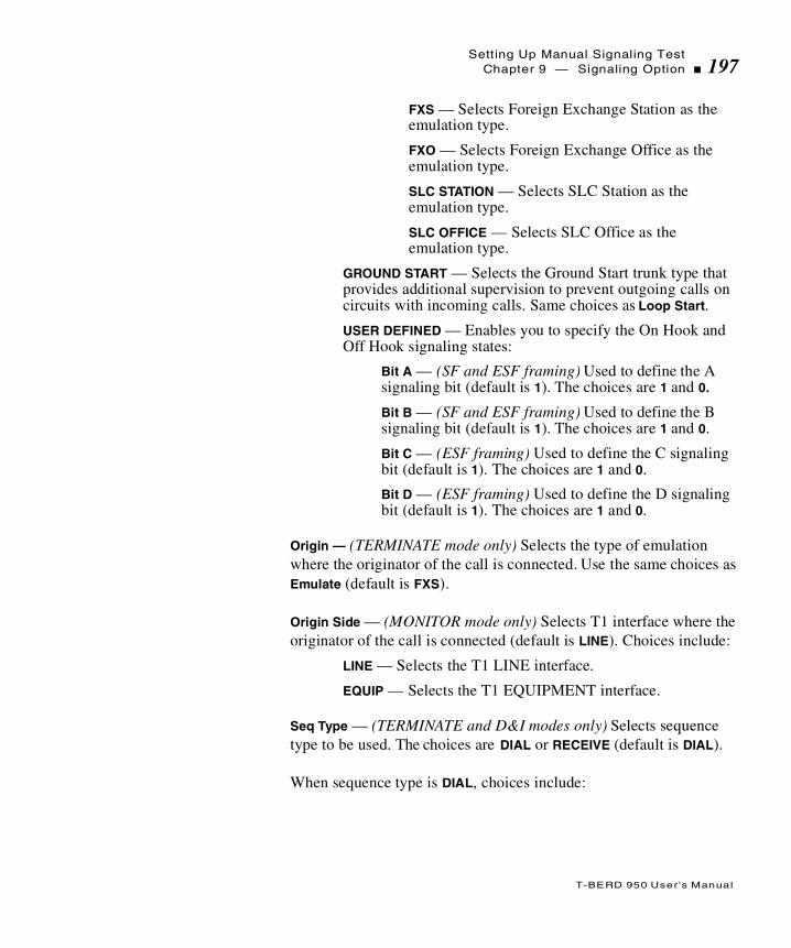
Setting Up Manual Signaling TestChapter 9 — Signaling Option 197
T-BERD 950 User ’s Manual
FXS — Selects Foreign Exchange Station as the emulation type.
FXO — Selects Foreign Exchange Office as the emulation type.
SLC STATION — Selects SLC Station as the emulation type.
SLC OFFICE — Selects SLC Office as the emulation type.
GROUND START — Selects the Ground Start trunk type that provides additional supervision to prevent outgoing calls on circuits with incoming calls. Same choices as Loop Start.
USER DEFINED — Enables you to specify the On Hook and Off Hook signaling states:
Bit A — (SF and ESF framing) Used to define the A signaling bit (default is 1). The choices are 1 and 0.
Bit B — (SF and ESF framing) Used to define the B signaling bit (default is 1). The choices are 1 and 0.
Bit C — (ESF framing) Used to define the C signaling bit (default is 1). The choices are 1 and 0.
Bit D — (ESF framing) Used to define the D signaling bit (default is 1). The choices are 1 and 0.
Origin — (TERMINATE mode only) Selects the type of emulation where the originator of the call is connected. Use the same choices as Emulate (default is FXS).
Origin Side — (MONITOR mode only) Selects T1 interface where the originator of the call is connected (default is LINE). Choices include:
LINE — Selects the T1 LINE interface.
EQUIP — Selects the T1 EQUIPMENT interface.
Seq Type — (TERMINATE and D&I modes only) Selects sequence type to be used. The choices are DIAL or RECEIVE (default is DIAL).
When sequence type is DIAL, choices include:

Setting Up Manual Signaling Test198 Chapter 9 — Signaling Option
T-BERD 950 User ’s Manual
Dial Seq — Selects the Call Origination sequence transmitted by the analyzer; both preprogramming sequences and manual dialing are selectable (default is PROGRAM 1). Choices include:
MANUAL DIAL — Enables manual dialing. Use the keypad and softkeys to place the call.
PROG N — Selects Dial Program N (where N is the number of the Dial Program sequence, 1 through 5.) as the sequence to be transmitted by the analyzer.
Dial Program N — (Where N is the number of the Dial Program sequence, 1 through 5.) Enables setting the Dial Program N pattern. (The program string can be up to 64 supervision event/digits, see Table 59, on page 190, for the valid supervision event symbols). Use the keypad to enter numeric values and the softkeys to enter supervision events.
(O)n Hook — Selects Originating On Hook supervision event.
Off (H)ook — Selects Originating Off Hook supervision event.
(R)ing — Selects Originating Ring supervision event.
(P)ause — Selects Origination Pause supervision event.
(w)ink — Selects Terminating Wink supervision event.
(d)elay dial — Selects Terminating Delay Dial supervision event.
(o)n hook — Selects Terminating On Hook supervision event.
off (h)ook — Selects Terminating Off Hook supervision event.
dial (t)one — Selects Terminating Dial Tone supervision event.
DTMF — Selects the Dual Tone Multifrequency digit type.
DP — Selects the Dial Pulse digit type.
MF — Selects the Multifrequency digit type.
Use the MORE key to access additional softkeys used in editing the sequence.

Setting Up Manual Signaling TestChapter 9 — Signaling Option 199
T-BERD 950 User ’s Manual
When RECEIVE is the selected sequence type the following parameters are available:
Rcv Seq — Selects the preprogramming Call Termination sequence to be used by the analyzer (default is PROGRAM 1). Choices include PROGRAM 1 through PROGRAM 5.
Rcv Program N — (Where N is the number of the Receive Program sequence, 1 through 5.) Enables setting the Rcv Program N pattern. (The program string can be up to 64 supervision event/digits, see Table 59 for the valid supervision event symbols). Use the keypad to enter numeric values and the softkeys to enter supervision events. Press More to cycle through the available softkey selections.
Dial Program N — (Where N is the number of the Receive Program sequence, 1 through 5.) Enables setting the Rcv Program N pattern. (The program string can be up to 64 supervision event/digits, see Table 59 for the valid supervision event symbols). Use the keypad to enter numeric values and the softkeys to enter supervision events. Press More to cycle through the available softkey selections.
(O)n Hook — Selects the Originating On Hook supervision event.
Off (H)ook — Selects the Originating Off Hook supervision event.
(R)ing — Selects the Originating Ring supervision event.
(G)nd on Ring — Selects the Ground on Ring supervision event.
(P)ause — Selects the Origination Pause supervision event.
(w)ink — Selects the Terminating Wink supervision event.
(o)n Hook — Selects the Terminating On Hook supervision event.
Notice the softkeys (O)n Hook and (o)n hook. These softkeys are not duplicates; each softkey performs a specific supervision event function.

Setting Up Manual Signaling Test200 Chapter 9 — Signaling Option
T-BERD 950 User ’s Manual
off (h)ook — Selects the Terminating Off Hook supervision event.
(d)elay dial — Selects the Terminating Delay Dial supervision event.
dial (t)one — Selects the Terminating Dial Tone supervision event.
Sig Scan — (Monitor mode only) Activates signaling scan feature, which enables the unit to automatically select the first channel on which signaling events are detected. Choices include:
Enable — Activates the signaling scan feature. The unit cycles through the channels sequentially and automatically selects the first channel on which an off-hook signaling event is detected. The selected channel is then displayed in the Test Type Setup and Results Views. Status of the signaling scan (enabled or disabled) is also displayed in the Results View.
Disable — Deactivates the signaling scan. The channel selected in the Interface Setup View will be used.
Call Control — Controls operation of pre-programmed signaling sequences. When pressed, the following softkeys are available:
Start Program N — (Where N is the number of the pre-programmed sequence, 1 through 5.) Starts the pre-programmed sequence.
On Hook — Provides an On Hook supervision event.
Once the Start Program N softkey has been pressed, the following softkeys are available:
Restart Program N — (Where N is the number of the pre-programmed sequence, 1 through 5.) Restarts the pre-programmed sequence.
Stop Program N — (Where N is the number of the pre-programmed sequence, 1 through 5.) Stops the pre-programmed sequence.

Test ResultsChapter 9 — Signaling Option 201
T-BERD 950 User ’s Manual
Test Results
Test results for the Signaling option are shown on the analyzer Two-Line Display. The Two-Line Display and associated controls and indicators are located on the front panel above the keypad. Refer to “Test Results Display” on page 90 for a detailed description of the Results Display.
Test results also appear on the Results view (refer to “Results View” on page 33).
Summary Category Results
The Summary category automatically lists out of specification key results. If all results are within specification for the LINE or EQUIPMENT receiver, the message All Results OK appears on the appropriate side of the Two-Line Display.
Test Type Category Results
The Test Type category results are described in Table 63.
There are no Performance Category results for the Signaling Option. For details on the Interface, Signal, and Time Category test results, see “T1 Test Results” on page 92.
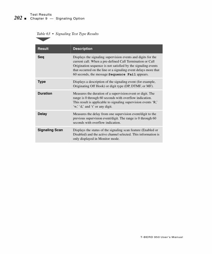
Test Results202 Chapter 9 — Signaling Option
T-BERD 950 User ’s Manual
Table 63 • Signaling Test Type Results
Result Description
Seq Displays the signaling supervision events and digits for the current call. When a pre-defined Call Termination or Call Origination sequence is not satisfied by the signaling events that occurred on the line or a signaling event delays more that 60 seconds, the message Sequence Fail appears.
Type Displays a description of the signaling event (for example, Originating Off Hook) or digit type (DP, DTMF, or MF).
Duration Measures the duration of a supervision event or digit. The range is 0 through 60 seconds with overflow indication. This result is applicable to signaling supervision events ‘R,’ ‘w,’ ‘d,’ and ‘t’ or any digit.
Delay Measures the delay from one supervision event/digit to the previous supervision event/digit. The range is 0 through 60 seconds with overflow indication.
Signaling Scan Displays the status of the signaling scan feature (Enabled or Disabled) and the active channel selected. This information is only displayed in Monitor mode.

T
T-BERD 950 User ’s Manual
his section provides step-by-step instructions for the PCM TIMS (Pulse Code Modulation Transmission Impairment Measurement Set)
option for the T-BERD 950. and discusses the following topics:
Option Description
TNT Setups
Manual Test Setups
Test Results
PCM TIMS Option

Option Description204 Chapter 9 — PCM TIMS Option
T-BERD 950 User ’s Manual
Option Description
The PCM TIMS option enables the T-BERD 950 to perform Voice Frequency (VF) testing on µ-Law encoded PCM data. The external interface to the option is via the T1 interface (LINE or EQUIPMENT, or both).
Digital Signal Processing (DSP) based testing is performed on the PCM data accessed from a DS1 access point. All option testing can be performed on DS0 channel PCM data dropped or inserted from a T1 line. The speaker output can be from either the LINE or EQUIPMENT T1 input or from both T1 inputs simultaneously (user selectable).
With the PCM TIMS option installed, the analyzer has the capability to pass through signalling bits while performing D&I testing, or insert signalling bits while performing TERMINATE or D&I testing.
Operating Modes
The PCM TIMS option operates in one of the following T1 operating modes: Terminate, Drop & Insert, or Monitor mode. The following paragraphs provide a brief discussion of each mode.
Terminate Mode
Terminate mode separates both sides of a T1 path, terminates the input signal at the receive side, and generates a totally independent output signal.
Drop & Insert Mode
The D&I mode enables the analyzer to access specific channels from the T1 line while leaving the other channels unaffected.
Option DescriptionChapter 9 — PCM TIMS Option 205
T-BERD 950 User ’s Manual
Monitor Mode
In Monitor mode, the option measures the parameters of the received PCM data signal. The following results are provided with two receivers enabled: Level (with tone present), Frequency (with tone present), C Message Noise, C Notch Noise, C Message Signal to Noise Ratio, and DC Offset.
Test Routines
The PCM TIMS option operates in one of the following test routines: Holding Tone, Variable Tone, 3 Tones, or Quiet. The following paragraphs provide a brief discussion of each mode.
Holding Tone Test
The Holding Tone test (with one receiver and/or one transmitter enabled) transmits a tone to the channel under test and the following parameters are measured with the corresponding results provided: Level, Frequency, C Filter Signal to Noise Ratio, D Filter Signal to Noise Ratio, 3.4 Filter Signal to Noise Ratio, C Notch Noise, 3.4 kHz Flat with Notch Noise, D Notch Noise, DC Offset, Dropouts, and Impulse Noise.
Variable Tone Test
The Variable Tone test transmits the selected tone frequency (from 20 to 3904 Hz) as is the level of the tone (from 3.0 through -40.0 dBm). The following results are provided: Level, Frequency, and DC Offset.
Only one set of measurements (C, D, or 3.4) can be derived at a time.

Setting Up TNT206 Chapter 9 — PCM TIMS Option
T-BERD 950 User ’s Manual
3 Tones Test
The 3 Tone test (with one receiver and/or one transmitter enabled) measures the frequency response of a channel at three frequencies: 404, 1004, and 2804 Hz. The 3 tones are transmitted automatically and repetitively as a sweep. The transmission time of each tone is adjustable from 2 to 15 seconds (the default is 5 seconds). The following parameters are measured with the corresponding results are provided: 404 Hz Level, 404 Hz Frequency, 1004 Hz Level, 1004 Hz Frequency, 2804 Hz Level, and 2804 Hz Frequency. A result takes approximately 4 seconds to appear on the Results view.
Quiet Test
Quiet test (with one receiver and/or one transmitter enabled) is used to perform noise measurements on a PCM data circuit when no tones are present and one end of the circuit has been terminated. To simulate this condition, a code representing zero signal (0xFE) is inserted on the channel under test. This test provides the following results: C Message Noise, D Message Noise, 3.4 kHz Flat Noise, DC Offset, and Impulse Noise.
Setting Up TNT
This section describes the TNT test setups to perform a T1 Interface PBX/Switch Turn-up.
Only one set of measurements (C, D, or 3.4) can be performed at a time.

Setting Up TNTChapter 9 — PCM TIMS Option 207
T-BERD 950 User ’s Manual
Performing T1 Interface PBX/Switch Turn-up
Table 64 lists the TNT test setup for PBX/Switch Turn-up TIMS Test. For descriptions of the test setup parameters, see “Setting Up the T1 Interface View” on page 62. For descriptions of all results see “T1 Test Results” on page 92.
The objective of this test is to verify the DSO does not have excessive loss or noise, which will result in poor voice quality. Usually a 1004Hz loss or C-message noise measurement is made.
Table 64 • T1 Interface PBX/Switch Turn-up
Test TNT Setup Results Summary
TIMS (Lvl/Noise) Test
In this scenario, the TB950 is one unit used to perform TIMS measurements along with another analog TIMS unit located on a 2-wire pair at the customer premise. The access at the customer premise is typically a punch down block.
Framing (ESF)Channel (1)Line Coding (B8ZS)Drop to Speaker (BOTH)Test (VARIABLE TONE)Transmit Level (0)Transmit Frequency (1004)Mode (D&I) Insert Side (LINE TX)Insert Payload (OFF) *
* User is instructed to turn this ON.
(IF MODE = TERMINATE)Tx Timing
BPVsCRC ErrorsT1 Rcv FrqT1 Rcv Lvl
Use TEST TYPE Results for specific TIMS test.
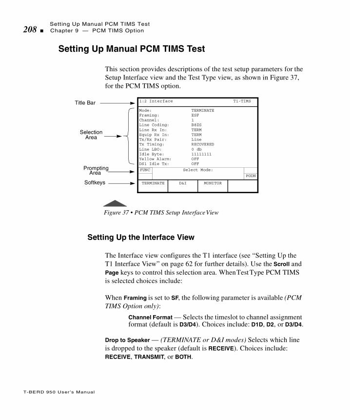
Setting Up Manual PCM TIMS Test208 Chapter 9 — PCM TIMS Option
T-BERD 950 User ’s Manual
Setting Up Manual PCM TIMS Test
This section provides descriptions of the test setup parameters for the Setup Interface view and the Test Type view, as shown in Figure 37, for the PCM TIMS option.
Figure 37 • PCM TIMS Setup Interface View
Setting Up the Interface View
The Interface view configures the T1 interface (see “Setting Up the T1 Interface View” on page 62 for further details). Use the Scroll and Page keys to control this selection area. When Test Type PCM TIMS is selected choices include:
When Framing is set to SF, the following parameter is available (PCM TIMS Option only):
Channel Format — Selects the timeslot to channel assignment format (default is D3/D4). Choices include: D1D, D2, or D3/D4.
Drop to Speaker — (TERMINATE or D&I modes) Selects which line is dropped to the speaker (default is RECEIVE). Choices include: RECEIVE, TRANSMIT, or BOTH.
Title Bar
SelectionArea
Mode: TERMINATEFraming: ESFChannel: 1Line Coding: B8ZSLine Rx In: TERMEquip Rx In: TERMTx/Rx Pair: LineTx Timing: RECOVEREDLine LBO: 0 dbIdle Byte: 11111111Yellow Alarm: OFFDS1 Idle Tx: OFF
Prompting
Softkeys
1:2 Interface T1-TIMS
PGDN
FUNC Select Mode:
D&I MONITORTERMINATE
Area

Setting Up Manual PCM TIMS TestChapter 9 — PCM TIMS Option 209
T-BERD 950 User ’s Manual
When SF is set to Monitor, choices include LINE, EQUIPMENT, or BOTH.
ABCD Bits Thru — (D&I mode) Selects whether signalling bits are passed through the analyzer (default is YES). Choices include: YES and NO. This parameter can be set to NO only if INS Payload is ON. (This is not available in Terminate mode.)
When ABCD Bits Thru is set to NO (or when mode is set to TERMINATE) and the Framing is set to SF or ESF, choices include (note that Bits C and D are for ESF framing only):
Bit A — Sets the A signalling bit (default is 0). The choices are 0 or 1.
Bit B — Sets the B signalling bit (default is 1). The choices are 0 or 1.
Bit C — Sets the C signalling bit (default is 1). The choices are 0 or 1.
Bit D — Sets the D signalling bit (default is 1). The choices are 0 or 1.
Setting Up the Test Type View
PCM TIMS Test Type view configures the PCM TIMS test. The Scroll and Page keys control this selection area.
In Terminate mode, ABCD Bits Thru does not appear.
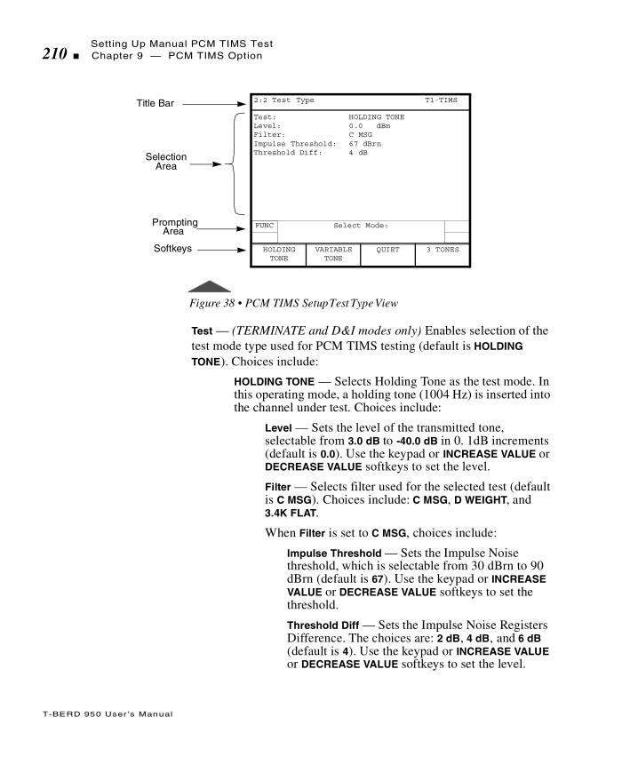
Setting Up Manual PCM TIMS Test210 Chapter 9 — PCM TIMS Option
T-BERD 950 User ’s Manual
Figure 38 • PCM TIMS Setup Test Type View
Test — (TERMINATE and D&I modes only) Enables selection of the test mode type used for PCM TIMS testing (default is HOLDING TONE). Choices include:
HOLDING TONE — Selects Holding Tone as the test mode. In this operating mode, a holding tone (1004 Hz) is inserted into the channel under test. Choices include:
Level — Sets the level of the transmitted tone, selectable from 3.0 dB to -40.0 dB in 0. 1dB increments (default is 0.0). Use the keypad or INCREASE VALUE or DECREASE VALUE softkeys to set the level.
Filter — Selects filter used for the selected test (default is C MSG). Choices include: C MSG, D WEIGHT, and 3.4K FLAT.
When Filter is set to C MSG, choices include:
Impulse Threshold — Sets the Impulse Noise threshold, which is selectable from 30 dBrn to 90 dBrn (default is 67). Use the keypad or INCREASE VALUE or DECREASE VALUE softkeys to set the threshold.
Threshold Diff — Sets the Impulse Noise Registers Difference. The choices are: 2 dB, 4 dB, and 6 dB (default is 4). Use the keypad or INCREASE VALUE or DECREASE VALUE softkeys to set the level.
Title Bar
SelectionArea
Test: HOLDING TONELevel: 0.0 dBmFilter: C MSGImpulse Threshold: 67 dBrnThreshold Diff: 4 dB
Prompting
Softkeys
2:2 Test Type T1-TIMS
FUNC Select Mode:
VARIABLE TONE
QUIET 3 TONESHOLDINGTONE
Area
Setting Up Manual PCM TIMS TestChapter 9 — PCM TIMS Option 211
T-BERD 950 User ’s Manual
VARIABLE TONE — Selects Variable Tone as the test mode. Choices include:
Level — Sets the level of the transmitted tone, selectable from 3.0 dB to -40.0 dB in 0. 1dB increments (default is 0.0). Use the keypad or INCREASE VALUE or DECREASE VALUE softkeys to set the level.
Frequency — Sets frequency of transmitted tone, selectable from 20 Hz to 3904 Hz. Use the keypad or INCREASE VALUE or DECREASE VALUE softkeys to set the tone frequency.
QUIET — Selects Quiet Tone (no tone) as the test mode. Choices include:
Filter — Selects filter used for selected test (default is C MSG). Choices include: C MSG, D WEIGHT, and 3.4K FLAT.
When Filter is set to C MSG, choices include:
Impulse Threshold — Sets the Impulse Noise threshold, which is selectable from 30 dBrn to 90 dBrn (default is 67). Use the keypad or INCREASE VALUE or DECREASE VALUE softkeys to set the threshold.
Threshold Diff — Sets the Impulse Noise Registers Difference. The choices include: 2 dB, 4 dB, and 6 dB (default is 4). Use the keypad or INCREASE VALUE or DECREASE VALUE softkeys to set the level.
3 TONES — Selects 3 Tone Slope as the test mode. Choices include:
Level — Sets the level of the transmitted tones, adjustable from 3.0 dB to -40.0 dB in 0. 1dB increments (default is 0.0). Use the keypad or INCREASE VALUE or DECREASE VALUE softkeys to set the level.
Tone Duration — Sets the length of time that tones are transmitted, selectable from 4 through 15 seconds in increments of 1 second (default is 5). Use the keypad or INCREASE VALUE or DECREASE VALUE softkeys to set the time.

Test Results212 Chapter 9 — PCM TIMS Option
T-BERD 950 User ’s Manual
Front Panel Keys
The following analyzer front panel keys are used in conjunction with the PCM TIMS option.
LOOP UP — Transmits the 2713 Hz loop up tone at a fixed level of -10.0 dBm, until the far end is looped. Loop up is recognized when the receiver detects the 2713 Hz tone on the line.
LOOP DOWN — Transmits the 2713 Hz loop down tone at a fixed level of -10.0 dBm, until the far end is looped down. Loop down is recognized when the receiver no longer detects the 2713 Hz tone on the line.
VOLUME CONTROL (Up and Down) — Sets the volume of the speaker.
Test Results
PCM TIMS option test results are shown on the analyzer Two-Line Display. The Two-Line Display and associated controls and indicators are located on the front panel above the keypad. Refer to “Test Results Display” on page 90 for a detailed description of the Results Display.
Test results as shown in Figure 39 also appear on the Large Graphical Display Results view (see “Results View” on page 33).

Test ResultsChapter 9 — PCM TIMS Option 213
T-BERD 950 User ’s Manual
Figure 39 • PCM TIMS Test Type Results View
Summary Category Results
The Summary category automatically lists out of specification key results. If all results are within specification for the LINE or EQUIPMENT receiver, the message All Results OK appears on the appropriate side of the Two-Line Display.
Test Type Category Results
The Test Type category results are described in Table 65.
There are no Performance Category results for the PCM TIMS Option. For details on the Interface, Signal and Time Category test results see “T1 Test Results” on page 92.
Title Bar
SelectionArea
LINELvl,dBmFreq, HzC Fil S/NC-Msg, dBrnCC-Nch, dBrnCDC-Off, mVImp Noise HImp Noise MImp Noise LDropouts
Prompting
Softkeys
3:7 Test Type T1-TIMS
PGDN
FUNC Press HELP for Additional Result Information.
PRINTSCREEN
Area

Test Results214 Chapter 9 — PCM TIMS Option
T-BERD 950 User ’s Manual
Table 65 • PCM TIMS Test Type Results
Result Name Description
Freq, Hz(Frequency)
Measures VF frequency in Hertz from 20 to 3904 Hz with an accuracy of 1 Hz. Result available in MONITOR operating mode and HOLDING TONE and VARIABLE TONE test modes.
Lvl, dBm (Level)
Measures VF level in dBm, with an accuracy of 0.2 dB from 200 Hz to 3900 Hz (+3 dBm to -40.0 dBm) and 0.1 dB from 1002 Hz to 1022 Hz (0 to -19 dBm). Result available in MONITOR operation mode, HOLDING TONE, and VARIABLE TONE test modes.
C Fil S/N (C Filter Signal to Noise Ratio)
Calculates ratio in dB, (using C-Message weighting) of the power of the test tone signal to the power of the background noise on the channel under test (accuracy is 1 dB, from 0 to 45 dB). For this measurement, a 1004 Hz tone is transmitted or 0xFE is inserted in the channel under test. Result available in MONITOR operating mode and HOLDING TONE and QUIET test modes.
C-Msg, dBrnC (C-Message Noise)
Measures (using C-Message weighting) the noise on an idle channel or circuit (a channel or circuit with a termination at one end and no holding tone at the transmitting end), expressed in dBrnC. Measurement range is 22 to 90 dBrnC with 1 dBrnC resolution. Result available in MONITOR operating mode and QUIET test modes.
C-Nch, dBrnC (C-Notch Noise)
Measures (using C-Message weighting and a 1010 Hz notch filter) the noise power on a channel with a holding tone at the transmitted end, expressed in dBrnC. Measurement range is 22 to 90 dBrnC with 1 dBrnC resolution. Result available in MONITOR operating mode and HOLDING TONE test mode.
D Fil S/N (D Filter Signal to Noise Ratio)
Calculates ratio in dB, (using D-Message weighting) of the power of the test tone signal to the power of the background noise on the channel under test (accuracy is 1 dB, from 0 to 45 dB). For this measurement, a 1004 Hz tone is transmitted or 0xFE is inserted in the channel under test. Result available in HOLDING TONE test modes.

Test ResultsChapter 9 — PCM TIMS Option 215
T-BERD 950 User ’s Manual
D Wgt Noise (D-Weighting Noise)
Measures (using D-Message weighting) the noise on an idle channel or circuit (a channel or circuit with a termination at one end and no holding tone at the transmitting end), expressed in dBrnD. Measurement range is 22 to 90 dBrnD with 1 dBrnD resolution. Result available in QUIET test mode.
D Nch Noise (D Notch Noise)
Measures (using D-Message weighting and a 1010 Hz notch filter) the noise power on a channel with a holding tone at the transmitted end, expressed in dBrnD. Measurement range is 22 to 90 dBrnD with 1 dBrnD resolution. Result available in HOLDING TONE test mode.
DC-Off, mV (DC-Offset)
Measures DC offset from -128 mV to 128 mV with a resolution of 1 mV. Result available in MONITOR operating mode and HOLDING TONE, VARIABLE TONE, and QUIET test modes.
Dropouts Counts holding tones having levels that decreased by 12 dB (±1 dB) or more from the level established at the start of the current test, and for a period of time greater than the qualification interval (4 ± ½ periods of the holding tone). Result available in HOLDING TONE mode.
Imp Noise H (Impulse Noise High Count)
Counts signals exceeding the Impulse Noise threshold by 6 dB, threshold accuracy is ±1 dB. Result available in HOLDING TONE and QUIET test modes.
Imp Noise M (Impulse Noise Medium Count)
Counts signals exceeding the Impulse Noise threshold by 4 dB, threshold accuracy is ±1 dB. Result available in HOLDING TONE and QUIET test modes.
Imp Noise L (Impulse Noise Low Count)
Counts signals exceeding the Impulse Noise threshold by 2 dB, threshold accuracy is ±1 dB. Result available in HOLDING TONE and QUIET test modes.
Table 65 • PCM TIMS Test Type Results (Continued)
Result Name Description
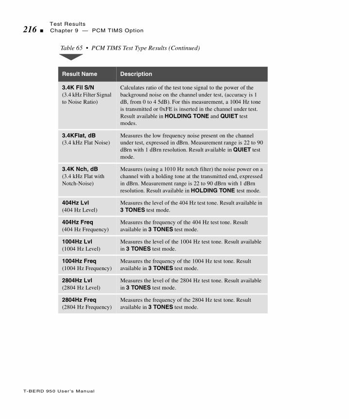
Test Results216 Chapter 9 — PCM TIMS Option
T-BERD 950 User ’s Manual
3.4K Fil S/N (3.4 kHz Filter Signal to Noise Ratio)
Calculates ratio of the test tone signal to the power of the background noise on the channel under test, (accuracy is 1 dB, from 0 to 4 5dB). For this measurement, a 1004 Hz tone is transmitted or 0xFE is inserted in the channel under test. Result available in HOLDING TONE and QUIET test modes.
3.4KFlat, dB (3.4 kHz Flat Noise)
Measures the low frequency noise present on the channel under test, expressed in dBrn. Measurement range is 22 to 90 dBrn with 1 dBrn resolution. Result available in QUIET test mode.
3.4K Nch, dB (3.4 kHz Flat with Notch-Noise)
Measures (using a 1010 Hz notch filter) the noise power on a channel with a holding tone at the transmitted end, expressed in dBrn. Measurement range is 22 to 90 dBrn with 1 dBrn resolution. Result available in HOLDING TONE test mode.
404Hz Lvl (404 Hz Level)
Measures the level of the 404 Hz test tone. Result available in 3 TONES test mode.
404Hz Freq (404 Hz Frequency)
Measures the frequency of the 404 Hz test tone. Result available in 3 TONES test mode.
1004Hz Lvl (1004 Hz Level)
Measures the level of the 1004 Hz test tone. Result available in 3 TONES test mode.
1004Hz Freq (1004 Hz Frequency)
Measures the frequency of the 1004 Hz test tone. Result available in 3 TONES test mode.
2804Hz Lvl (2804 Hz Level)
Measures the level of the 2804 Hz test tone. Result available in 3 TONES test mode.
2804Hz Freq (2804 Hz Frequency)
Measures the frequency of the 2804 Hz test tone. Result available in 3 TONES test mode.
Table 65 • PCM TIMS Test Type Results (Continued)
Result Name Description

T
T-BERD 950 User ’s Manual
his section provides step-by-step instructions for using the Basic RateInterface (BRI) ISDN option for the T-BERD 950 and discusses the
following topics:
Option Description
TNT Setups
Manual Test Setups
Test Results
ISDN BRI Option

Option Description218 Chapter 9 — ISDN BRI Option
T-BERD 950 User ’s Manual
Option Description
The ISDN BRI option, in conjunction with the Protocol Services Board option, enables the T-BERD 950 Communications Analyzer to perform the following:
BER testing
Protocol analysis (D-channel analysis)
Voice and data (call placement and receipt)
X.25 D-channel packet calls
The ISDN BRI interface generates required frames for terminal initialization, Layer 2 start-up, and basic call processing for the AT&T 5ESS, NT DMS 100, and National standards. It gathers and processes the proper call setup information for two simultaneous calls and the proper frames to maintain the call connections simultaneously.
The BRI module provides physical layer status and statistics for the U interface side of the ISDN network. These include activation status, U interface sealing current, and framing status. Block errors are also counted. See “Test Results” on page 246 for detailed results information.
The ISDN BRI option originates two circuit-switched calls, terminates two circuit-switched calls, or originates one circuit-switched call while terminating a second circuit-switched call. In addition, the unit can place and/or receive X.25 Packet Data calls over the D-channel.
When the call setup acknowledge message is received for incoming or outgoing calls, it connects the speaker and microphone for that call. You can also change the connection of the call dynamically. A call connected to BERT can be changed to connect to the speaker/microphone.

Option DescriptionChapter 9 — ISDN BRI Option 219
T-BERD 950 User ’s Manual
If the ISDN BRI option is connected to two voice calls simultaneously, Call 1 is connected to the push-to-talk interface and a holding tone is placed on Call 2. If two data calls are connected, then the BERT settings are the same on both calls. The unit measures the loopback delay for each B-channel. After the D-packet call is connected, the analyzer can send the FOX message, show the received data, and provide X.25 packet analysis.
U Interface
The ISDN BRI option is capable of emulating the ISDN Terminal Equipment (TE) device from the U access point.
The NT1 is the first customer premise device on a two-wire ISDN circuit coming in from the ISDN CO. It accomplishes several tasks. It converts the two-wire ISDN circuit (called a U interface) to a four-wire S/T so you can connect several terminals. The NT1 CO can thereby “talk” to the NT1 and do testing and maintenance by instructing the NT1 to loop signals back to the CO.
Interface Between NT and the Network
The U reference point describes the interface between the Network Termination (NT) and the network Line Termination (LT). It is a two-wire interface with 2B1Q line coding. The network provides power via the U interface. Figure 40 shows the relationship between the customer premises and the local loop for the S/T and U interfaces.

Option Description220 Chapter 9 — ISDN BRI Option
T-BERD 950 User ’s Manual
.
Figure 40 • ISDN BRI S/T and U Reference Points
Operating Modes
You can configure the ISDN BRI option to operate in these modes:
Line Termination (LT) BERT Mode
Network Termination (NT) BERT Mode
Network Termination and Terminal Equipment (NT1/TE) Mode
Detailed descriptions of these modes of operation are found below.
LT BERT Mode
The purpose of the LT mode is to BERT the physical layer of the U interface toward the NT device. This mode is not capable of placing or receiving a call. This mode can BERT the B1, B2, B1 and B2, or 2B+D-channels. The BERT operations can either be end-to-end (with another BERT device on the NT side) or looped back. Phantom power is not provided. Figure 41 shows BER testing using full or partial bandwidth for this mode.
Customer Premises
TA TE2
Local Loop NT1
TE1
Network
Network
S/T Interface U Interface
LT
BRITE
(2w Interface)
Channel Bank

Option DescriptionChapter 9 — ISDN BRI Option 221
T-BERD 950 User ’s Manual
The ISDN BRI option can request loopbacks on the B1, B2, B1 and B2, or 2B+D-channel.
Figure 41 • ISDN BRI LT Terminate Mode
NT1 BERT Mode
The purpose of the Network Termination (NT1) mode is to test the physical layer of the U interface toward the LT device. The NT1 mode cannot place a call, but it can BERT the B1, B2, B1 and B2, or 2B+D-channels. The test operations can only be in end-to-end, with another BERT device on the LT side. Figure 42 shows testing using full or partial bandwidth for this mode.
In NT1 mode, the U interface can be looped back manually or via the EOC messages received from the LT. The BRI interface can loopback the B1, B2, B1 and B2, or 2B+D-channel.
Figure 42 • ISDN BRI NT1 Terminate Mode
ConnectorTo NT
U Interface 2B1Q
T-BERD 950
NT1or Test Equipment
T-BERD 950
U Interface 2B1Q
Network or TestEquipment
To LT
Connector

Option Description222 Chapter 9 — ISDN BRI Option
T-BERD 950 User ’s Manual
NT1/TE Mode
The T-BERD 950 can originate and terminate Circuit-Switched Voice (CSV), Circuit-Switched Data (CSD) 56K, and 64K Unrestricted calls. In addition to the circuit operations listed above, the unit can originate and terminate D-packet switched calls.
The NT1/TE mode allows the unit to emulate a Network Termination (NT1) and Terminal Equipment (TE) simultaneously. This mode is used to place calls at the U interface. The ISDN BRI option emulates Terminal Equipment (TE) at the U interface and is available with the ISDN test type. In the NT1/TE mode, you can manually loopback the U interface. Figure 43 shows ISDN calls placed and received using the D-channel for either B-channel.
Figure 43 • ISDN BRI NT1/TE in Terminate Mode
Call-generating capabilities include the ability to vary the type of service to connect. You can generate either 56 kbps or 64 kbps calls. Either call connects to the BERT engine or the push-to-talk interface based on the Bearer Destination.
Calls can be placed or received on either B-channel and dropped to the BERT engine or speaker and microphone (with DTMF dialing). After a call is connected, the B-channel(s) destination (either the BERT engine or speaker and microphone) for that call can be changed without disconnecting the call. The ISDN BRI option can loopback the B1, B2, or B1 and B2 channel.
T-BERD 950
U Interface
2B1Q
Network or TestEquipment
To LT
Connector

Option DescriptionChapter 9 — ISDN BRI Option 223
T-BERD 950 User ’s Manual
Manual and EOC Loopbacks
Depending on your mode of operation, the T-BERD 950 can be looped back manually or via Embedded Operations Channel (EOC) messages. These loopbacks are logical in that they loop the selected bandwidth. (See Table 66 for information on the different types of loopbacks available in each BRI mode.)
In LT mode, you configure the type of loopback and press the Loop Up key to loop up the far end. The ISDN BRI option then transmits an EOC loopback request to the NT device. Press the Loop Down key to deactivate these loopbacks.
In NT1 mode, EOC automated loopback requests are enabled from the user interface. A status message appears on the Results I and II Display that announces an active loopback. Any manual loopbacks are configured from the user interface.
External Interface Requirements
The ISDN BRI option provides two RJ-45 8-pin modular jacks. The RJ connectors support BER testing, protocol analysis, and emulation over the B and D-channel. Table 67 describes the To LT and To NT connectors on the U interface.
Table 66 • ISDN BRI Loopbacks
BRI Mode Loopback Type Loopbacks Available
LT Sends EOC loopback requests to the NT
B1, B2, B1 and B2, 2B+D
NT1 Either manual or responds to EOC loopback requests
B1, B2, B1 and B2, 2B+D
NT1/TE Manual loopbacks B1, B2, B1 and B2
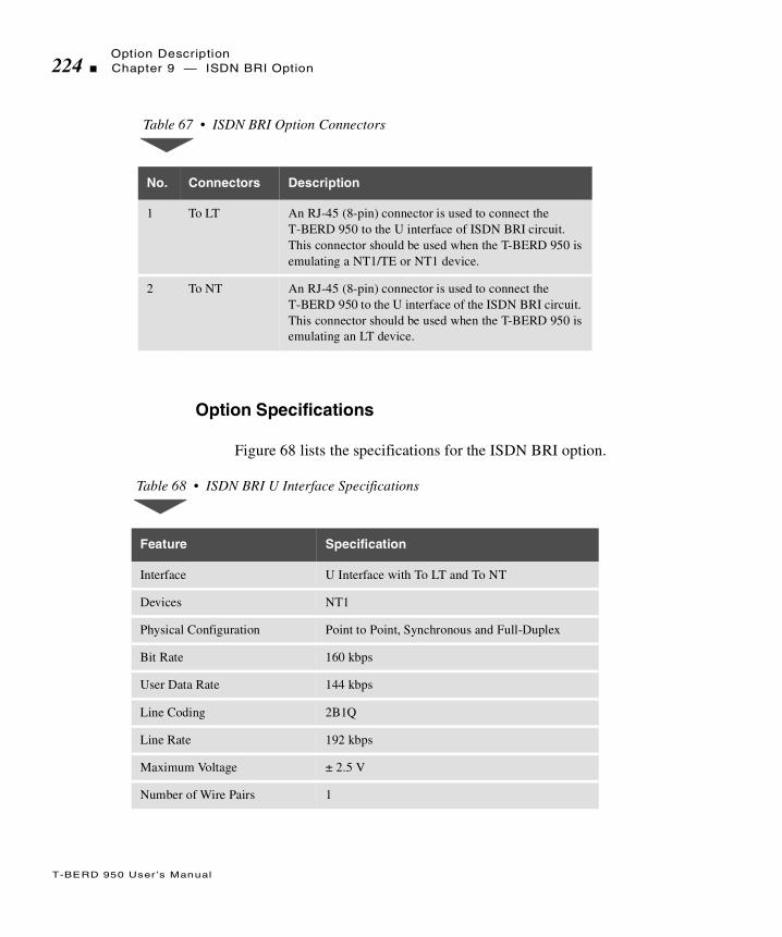
Option Description224 Chapter 9 — ISDN BRI Option
T-BERD 950 User ’s Manual
Option Specifications
Figure 68 lists the specifications for the ISDN BRI option.
Table 67 • ISDN BRI Option Connectors
No. Connectors Description
1 To LT An RJ-45 (8-pin) connector is used to connect the T-BERD 950 to the U interface of ISDN BRI circuit. This connector should be used when the T-BERD 950 is emulating a NT1/TE or NT1 device.
2 To NT An RJ-45 (8-pin) connector is used to connect the T-BERD 950 to the U interface of the ISDN BRI circuit. This connector should be used when the T-BERD 950 is emulating an LT device.
Table 68 • ISDN BRI U Interface Specifications
Feature Specification
Interface U Interface with To LT and To NT
Devices NT1
Physical Configuration Point to Point, Synchronous and Full-Duplex
Bit Rate 160 kbps
User Data Rate 144 kbps
Line Coding 2B1Q
Line Rate 192 kbps
Maximum Voltage ± 2.5 V
Number of Wire Pairs 1

Setting Up TNTChapter 9 — ISDN BRI Option 225
T-BERD 950 User ’s Manual
Setting Up TNT
This section describes the TNT test setups for the ISDN BRI option. A sample TNT Setup view is shown in Figure 44.
Figure 44 • ISDN BRI TNT Setup View
Full-Duplex Method Echo Cancellation
Interleaving Scheme B18B28 (12X/Frame)
Bits Per Frame 240
Bits User Data 216
Bits Overhead 24
Frames Per Second 666.66666...
Table 68 • ISDN BRI U Interface Specifications (Continued)
Feature Specification
Title Bar
SelectionArea
Bert Pattern: 2047Switch: NATIONALNumbering Plan: NATIONAL-------------------Call 1---------------------Call Type: VOICECall Mode: MANUAL DIALProgram 1: 8442525Calling Number: 5551212
Prompting
Softkeys
3:3 TNT BRI Circuit Single Call
FUNC Select Switch:
AT&T NTNATIONAL
Area

Setting Up TNT226 Chapter 9 — ISDN BRI Option
T-BERD 950 User ’s Manual
Performing Line Qualification Test
Table 69 lists the TNT test setup for performing a line qualification test. For descriptions of the test setup parameters, see “Setting Up Manual BER Test” on page 230. For descriptions of all results see “Test Results” on page 246.
The objective of this test is perform a physical layer test of the U interface towards the LT or NT device. By sending or responding to EOC loopbacks, either B1, B2, B1 and B2, or 2B+D channels can be tested using a BERT pattern such as 2047. Physical layer results such as CRC errors, and bit errors are available. This is performed as a an out-of-service test in LT or NT mode.
Placing and Receiving Circuit Calls
Table 70 lists the TNT test setups for placing and receiving various types of circuit calls. For descriptions of the test setup parameters, see “Setting Up Manual ISDN Test” on page 234. For descriptions of all results see “Test Results” on page 246.
Table 69 • ISDN BRI Line Qualification Test
Test TNT Setup TNT Results
LINE QUALIFICATION (BERT)LT or NT emulation
In this scenario, the T-BERD 950 is used to send or respond to the appropriate EOC loopcode. Otherwise, the technician is performing end-to-end BER testing with someone else located at the far-end.
Test Mode (NT)Bert Pattern (2047)Channels (2B+D)
If channels = B1, B2 Rate (64K)
If Mode = LT Tx Loop (B1)
CRC ErrSeal CurLayer1 StatBit ErrorsPat SlipsBEREFSFEBE Err
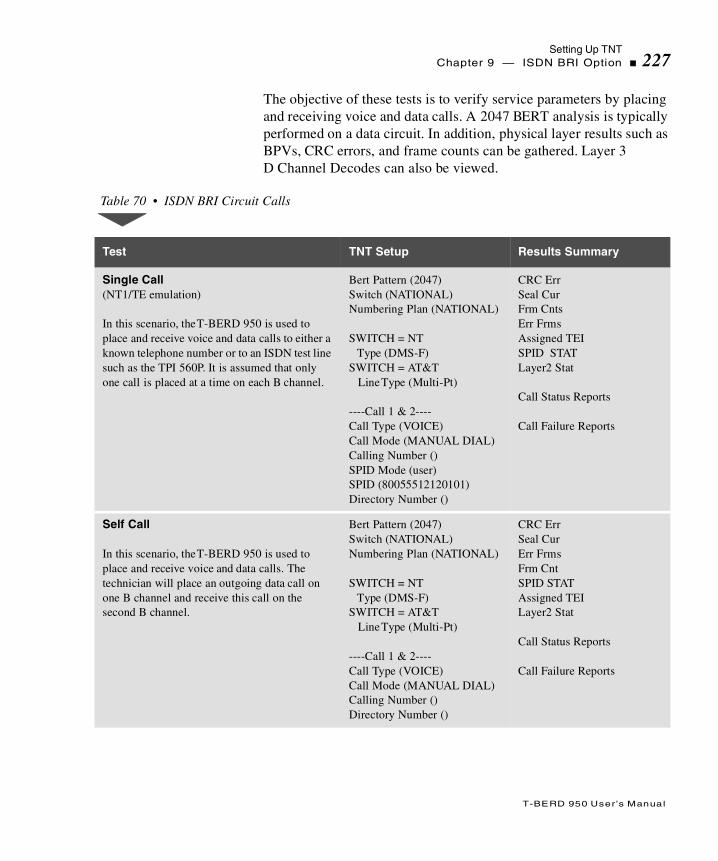
Setting Up TNTChapter 9 — ISDN BRI Option 227
T-BERD 950 User ’s Manual
The objective of these tests is to verify service parameters by placing and receiving voice and data calls. A 2047 BERT analysis is typically performed on a data circuit. In addition, physical layer results such as BPVs, CRC errors, and frame counts can be gathered. Layer 3 D Channel Decodes can also be viewed.
Table 70 • ISDN BRI Circuit Calls
Test TNT Setup Results Summary
Single Call(NT1/TE emulation)
In this scenario, the T-BERD 950 is used to place and receive voice and data calls to either a known telephone number or to an ISDN test line such as the TPI 560P. It is assumed that only one call is placed at a time on each B channel.
Bert Pattern (2047)Switch (NATIONAL)Numbering Plan (NATIONAL)
SWITCH = NT Type (DMS-F)SWITCH = AT&T Line Type (Multi-Pt)
----Call 1 & 2----Call Type (VOICE)Call Mode (MANUAL DIAL)Calling Number ()SPID Mode (user)SPID (80055512120101)Directory Number ()
CRC ErrSeal CurFrm CntsErr FrmsAssigned TEISPID STATLayer2 Stat
Call Status Reports
Call Failure Reports
Self Call
In this scenario, the T-BERD 950 is used to place and receive voice and data calls. The technician will place an outgoing data call on one B channel and receive this call on the second B channel.
Bert Pattern (2047)Switch (NATIONAL)Numbering Plan (NATIONAL)
SWITCH = NT Type (DMS-F)SWITCH = AT&T Line Type (Multi-Pt)
----Call 1 & 2----Call Type (VOICE)Call Mode (MANUAL DIAL)Calling Number ()Directory Number ()
CRC ErrSeal CurErr FrmsFrm CntSPID STATAssigned TEILayer2 Stat
Call Status Reports
Call Failure Reports
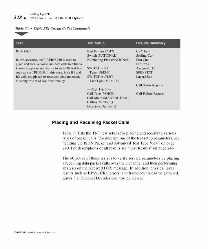
Setting Up TNT228 Chapter 9 — ISDN BRI Option
T-BERD 950 User ’s Manual
Placing and Receiving Packet Calls
Table 71 lists the TNT test setups for placing and receiving various types of packet calls. For descriptions of the test setup parameters, see “Setting Up ISDN Packet and Advanced Test Type View” on page 240. For descriptions of all results see “Test Results” on page 246.
The objective of these tests is to verify service parameters by placing a receiving data packet calls over the Dchannel and then performing analysis on the received FOX message. In addition, physical layer results such as BPVs, CRC errors, and frame counts can be gathered. Layer 3 D Channel Decodes can also be viewed.
Dual Call
In this scenario, the T-BERD 950 is used to place and receive voice and data calls to either a known telephone number or to an ISDN test line such as the TPI 560P. In this case, both B1 and B2 calls are placed or received simultaneously to verify true dual call functionality.
Bert Pattern (2047)Switch (NATIONAL)Numbering Plan (NATIONAL)
SWITCH = NT Type (DMS-F)SWITCH = AT&T Line Type (Multi-Pt)
----Call 1 & 2----Call Type (VOICE)Call Mode (MANUAL DIAL)Calling Number ()Directory Number ()
CRC ErrsSealing CurFrm CntsErr FrmsAssigned TEISPID STATLayer2 Stat
Call Status Reports
Call Failure Reports
Table 70 • ISDN BRI Circuit Calls (Continued)
Test TNT Setup Results Summary

Setting Up TNTChapter 9 — ISDN BRI Option 229
T-BERD 950 User ’s Manual
Table 71 • ISDN BRI Packet Calls
Test TNT Setup TNTN Results
0B+D Call (NT1/TE emulation)
In this scenario, the T-BERD 950 is used to place and receive data packets calls to either a known TE packet device or to an ISDN test line such as the TPI 560P.
Bert Pattern (2047)Switch (NATIONAL)Numbering Plan (NATIONAL)
SWITCH = NT Type (DMS-F)SWITCH = AT&T Line Type (Multi-Pt)
SPID Mode (USER)SPID (80055512120101)
----PACKET CALL----LCN (1)Packet Echo (OFF)Called Number ( )Calling Number ( )Call User Data (OFF)CUG Mode (OFF)
CRC ErrsSealing CurFrm CntsErr FrmsAssigned TEISPID STATLayer2 Stat
X.25 Call ResultRx REJ PktsPacket StatX.25 Call Failure ReportX.25 Call Data Result

Setting Up Manual BER Test230 Chapter 9 — ISDN BRI Option
T-BERD 950 User ’s Manual
Setting Up Manual BER Test
This section provides descriptions of the Test Setup parameters to perform a BER test. Use the Setup Interface and the Test Type views, as shown in Figure 45.
2B+D Call (NT1/TE emulation)
In this scenario, the T-BERD 950 is used to place and receive data packet and B channel voice and data calls to either a known telephone number or to an ISDN test line such as the TPI 560P.
Bert Pattern (2047)Switch (NATIONAL)Numbering Plan (NATIONAL)
SWITCH = NT Type (DMS-F)SWITCH = AT&T Line Type (Multi-Pt)
----Call 1 & 2----Call Type (VOICE)Call Mode (MANUAL DIAL)Calling Number ()SPID Mode (USER)SPID (80055512120101)Directory Number ()
----PACKET CALL----LCN (1)Packet Echo (OFF)Called Number ( )Calling Number ( )Call User Data (OFF)CUG Mode (OFF)
CRC ErrSealing CurFrm CountErr FrmAssigned TEISPID STATLayer2 Stat
Call Status ReportsCall Failure Reports
X.25 Call ResultRx REJ PktsPacket StatX.25 Call ResultX.25 Call Failure ReportX.25 Call Data Result
Table 71 • ISDN BRI Packet Calls (Continued)
Test TNT Setup TNTN Results
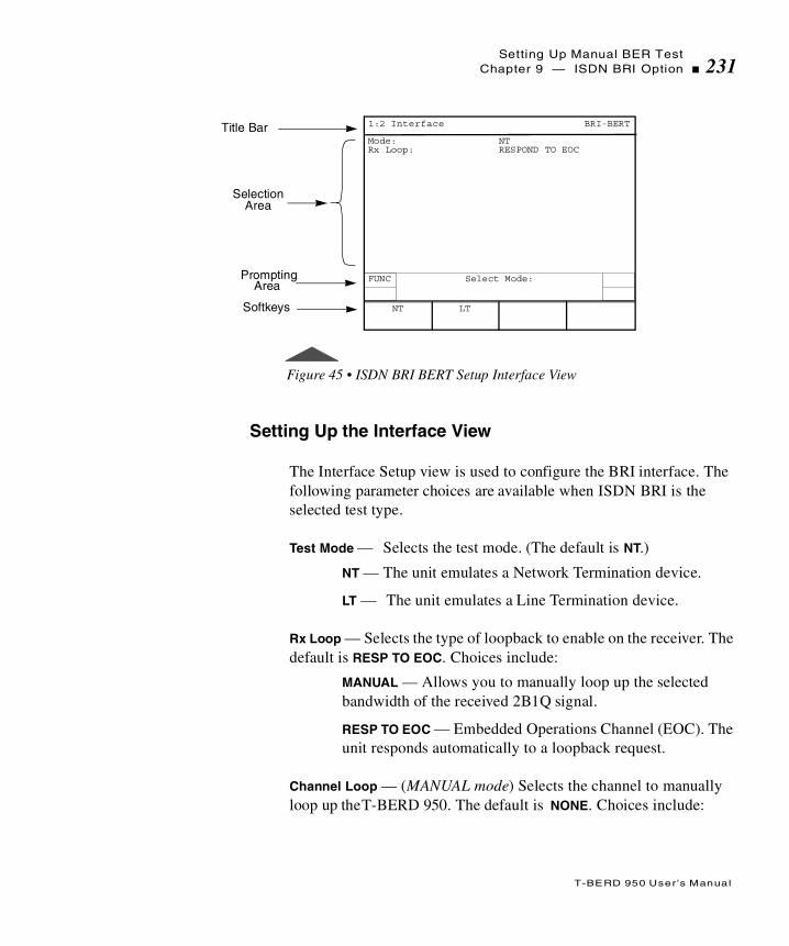
Setting Up Manual BER TestChapter 9 — ISDN BRI Option 231
T-BERD 950 User ’s Manual
Figure 45 • ISDN BRI BERT Setup Interface View
Setting Up the Interface View
The Interface Setup view is used to configure the BRI interface. The following parameter choices are available when ISDN BRI is the selected test type.
Test Mode — Selects the test mode. (The default is NT.)
NT — The unit emulates a Network Termination device.
LT — The unit emulates a Line Termination device.
Rx Loop — Selects the type of loopback to enable on the receiver. The default is RESP TO EOC. Choices include:
MANUAL — Allows you to manually loop up the selected bandwidth of the received 2B1Q signal.
RESP TO EOC — Embedded Operations Channel (EOC). The unit responds automatically to a loopback request.
Channel Loop — (MANUAL mode) Selects the channel to manually loop up the T-BERD 950. The default is NONE. Choices include:
Title Bar
SelectionArea
Mode: NTRx Loop: RESPOND TO EOC
Prompting
Softkeys
1:2 Interface BRI-BERT
FUNC Select Mode:
LTNT
Area

Setting Up Manual BER Test232 Chapter 9 — ISDN BRI Option
T-BERD 950 User ’s Manual
NONE — No channel selected to be looped back on the unit.
B1 — Selects channel B1 for the test.
B2 — Selects channel B2.
B1&B2 — Selects both B-channels.
2B+D — Selects both B-channels and the D-channel.
Tx Loop — (LT mode) Selects the type of EOC transmit to loop a far-end device. Choices include:
B1 — Selects channel B1.
B2 — Selects channel B2.
2B+D — Selects both B-channels and the D-channel.
Setting Up the Test Type View
The ISDN BRI BERT Test Type Setup view is used to configure the test to be performed (see Figure 46). The SCROLL and PAGE keys are used to control this selection area.
Figure 46 • ISDN BRI BERT Setup Test Type View
Title Bar
SelectionArea
Bert Pattern: 2047Channels: B1Bert Rate: 64KError insert Type: LOGIC
Prompting
Softkeys
2:2 Test Type BRI-BERT
FUNC Select Channels:
B2 B1+B2 2B+DB1
Area

Setting Up Manual BER TestChapter 9 — ISDN BRI Option 233
T-BERD 950 User ’s Manual
BERT Pattern — Selects the BERT pattern for the test. Refer to “Setting Up the T1 Test Type View” on page 80 for more information on these patterns. (The default is the 2047 pattern).
Channels — Selects the channel for the BER test. (The default is B1.) If your Channel selection is B1 or B2, you need to select the Bert Rate. Choices include:
B1 — Selects channel B1.
B2 — Selects channel B2.
B1&B2 — Selects both B-channels.
2B+D — Selects both B-channels and the D-channel.
Bert Rate — (B1 or B2) Selects the bearer channel data rate. Choices include:
56K — Selects an unrestricted circuit-switched data connection with 56 kbps CCITT I.463 rate adaptation.
64K — Selects a clear channel, unrestricted, circuit-switched data connection with the full 64 kbps available for use, with no rate adaptation.
Error Insert Type — Selects error type to be inserted in the data stream when the ERROR INSERT key is pressed (default is LOGIC). Choices include:
LOGIC —Enables insertion of bit (logic) errors. Single errors or an error rate can be selected using the ERROR INSERT key.
FEBE — Enables insertion of Far End Block Error (FEBE) framing, parity and out of frame (OOF) errors. Single errors or an error rate can be selected by using the ERROR INSERT key.
CRC —Enables insertion of Cyclic Redundancy Check (CRC) errors. Single errors or an error rate can be selected by using the ERROR INSERT key.
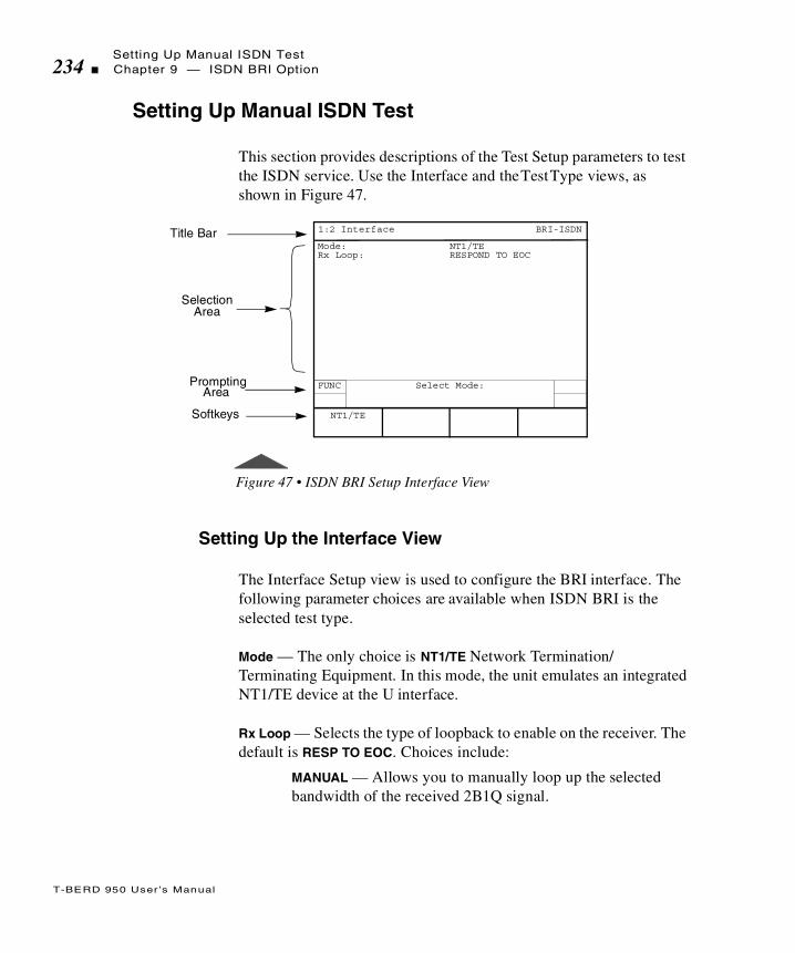
Setting Up Manual ISDN Test234 Chapter 9 — ISDN BRI Option
T-BERD 950 User ’s Manual
Setting Up Manual ISDN Test
This section provides descriptions of the Test Setup parameters to test the ISDN service. Use the Interface and the Test Type views, as shown in Figure 47.
Figure 47 • ISDN BRI Setup Interface View
Setting Up the Interface View
The Interface Setup view is used to configure the BRI interface. The following parameter choices are available when ISDN BRI is the selected test type.
Mode — The only choice is NT1/TE Network Termination/Terminating Equipment. In this mode, the unit emulates an integrated NT1/TE device at the U interface.
Rx Loop — Selects the type of loopback to enable on the receiver. The default is RESP TO EOC. Choices include:
MANUAL — Allows you to manually loop up the selected bandwidth of the received 2B1Q signal.
Title Bar
SelectionArea
Mode: NT1/TERx Loop: RESPOND TO EOC
Prompting
Softkeys
1:2 Interface BRI-ISDN
FUNC Select Mode:
NT1/TE
Area

Setting Up Manual ISDN TestChapter 9 — ISDN BRI Option 235
T-BERD 950 User ’s Manual
RESP TO EOC — Embedded Operations Channel (EOC). The unit responds automatically to a loopback request.
Channel Loop — (Manual) Selects the channel to loop up (default is NONE). Choices include:
NONE — No channel selected to be looped back on the unit.
B1 — Selects channel B1.
B2 — Selects channel B2
B1&B2 — Selects both B-channels.
2B+D — Selects both B-channels and the D-channel.
Setting Up the Test Type View
The ISDN BRI Test Type Setup view configures the test to be performed. The SCROLL and PAGE keys control this selection area.
Figure 48 • ISDN BRI Test Type Setup View
Bert Pattern — The BER test patterns are listed here. Refer to “Setting Up the T1 Test Type View” on page 80 for more information on these patterns (default is 2047).
Title Bar
SelectionArea
Bert Pattern: 2047---------------------------------------------
-Switch; NATIONALNumbering Plan; NATIONALTEI MOde; AUTO-------------------CALL 1---------------------Call Type: DATA 64KBearer Destination: SPEAKERBearer Channel; ANYCall Mode: MANUAL DIALCalling Number: 5551212SPID Mode: GUESS
Prompting
Softkeys
2:2 Test Type BRI-ISDN
FUNC
MORE
Select Bert Pattern:
2047 2047QRS T1-1Min/Max
511QRS
Area

Setting Up Manual ISDN Test236 Chapter 9 — ISDN BRI Option
T-BERD 950 User ’s Manual
Switch — Enables entry of the switch type used on the ISDN link (default is NATIONAL). Choices include:
NATIONAL — Selects National as the switch type.
AT&T — Selects the AT&T 5ESS Custom as the switch type. When AT&T is the switch type, the following parameter is available:
Line Type — Select the line type if the Switch is the AT&T 5ESS (default is MULT-PT). Choices include:
PT-PT — Selects a point-to-point circuit or two-point circuit.
MULTI-PT — Selects a multipoint circuit.
NT — Selects the Northern Telecom DMS 100 Custom as the switch type. When NT is the switch type, the following parameter is available:
Type — Selects the NT type (default is DMS-F). Choices include:
DMS-F — DMS Functional
DMS-S — DMS Stimulus
Number Plan — Enables the selection of the appropriate ISDN numbering plan for the desired circuit (default is NATIONAL). Numbering plan choices include:
UNKNOWN — Unknown number in numbering plan.
INTERNATIONAL — International number in ISDN numbering plan.NATIONAL — National number in the ISDN numbering plan.
NETWORK — Network-specific number in private numbering plan.
LOCAL — Local directory number in ISDN numbering plan.
ABBREVIATED — Abbreviated number in private numbering plan.

Setting Up Manual ISDN TestChapter 9 — ISDN BRI Option 237
T-BERD 950 User ’s Manual
TEI Mode — Terminal Equipment Identifier (TEI) (Circuit operation mode only) is part of the layer 2 link access procedure of D-channels (Q.921) address that identifies frames to and from a particular terminal (default is AUTO).
AUTO — Automatic TEI values selected by the network. Assigns TEI values 64-126.
FIXED — Non-automatic TEI user-selected values.
TEI — (Fixed) Choices for fixed assignment are [0-63] (default is 0).
Call Type — Selects the type of call to be generated by the unit (default is VOICE). Choices include:
DATA 56K — Selects an unrestricted circuit-switched data connection with 56 kbps CCITT I.463 rate adaptation.
DATA 64K — Selects a clear channel, unrestricted, circuit-switched data connection with the full 64 kbps available for use, with no rate adaptation.
VOICE — Selects a voice type call. If another call is connected to the SPKR (speaker/microphone combination), a tone is sent. Otherwise the call is connected through the speaker/mike combination.
3.1K AUD — Selects a 3.1 kHz audio call type.
Bearer Destination — Selects the appropriate destination of the connected call (default is SPEAKER). Choices include:
SPEAKER — The call is connected to speaker/microphone for voice conversation which allows you to place two voice calls. The first call connects to the speaker/microphone, the second connects to the 1004 Hz tone generator.
The following parameters must be set for both Call 1 and Call 2 when connecting to two calls simultaneously.
Setting Up Manual ISDN Test238 Chapter 9 — ISDN BRI Option
T-BERD 950 User ’s Manual
BERT— BER testing is performed on the selected channels of the connected call.
Bearer Channel — Enables selection of the bearer (B) channel for the call (default is ANY). Choices include:
ANY — Allows the switch to allocate the bearer channel.B1 — Selects bearer channel 1.
B2 — Selects bearer channel 2.
Call Mode — Selects MANUAL DIAL or the appropriate Program Number Program (N). PROGRAM 1 through PROGRAM 5 (for Call 1), and PROGRAM 6 through PROGRAM 10 (for Call 2).
MANUAL DIAL — Enables manual entry of the number to be called.
Program (N) — Enables entry of number to be called, up to 18 digits (default is 8441212). Program up to five numbers on PROG 1 through PROG 5 (for Call 1), and five numbers on PROG 6 through PROG 10 (for Call 2). Use the keypad to edit this field.
Calling Number — Enables entry of the Directory Number (DN) of the circuit being analyzed, up to 15 digits (default is 8441212). Use the keypad to edit this field.
SPID Mode — This is the Service Profile ID, which identifies the types of services and features supported for a given device. SPIDs are optional in the ISDN standard, but usually required in North America (default is USER).
GUESS — The unit will attempt to add the most common prefix and suffix on the Directory number (DN) depending on the switch selected. Table 72 shows the combinations, in
Bearer Destination determines where the call is initially connected. Once the call is connected, it can be switched between the BERT engine and the Speaker using the softkeys.

Setting Up Manual ISDN TestChapter 9 — ISDN BRI Option 239
T-BERD 950 User ’s Manual
order, the T-BERD 950 uses when performing a SPID Guess. For example, if the configured directory number is 800.555.1212, then the seven digits used would be 555.1212.
DN — (Guess) Enter the [7-16 digits] (default is 8005551212).
Table 72 • ISDN BRI SPID Guess Tabl e
Prefix# Directory Number Digits Used
Suffix
01 7 000
NONE 10 0100
NONE 10 0101
01 7 0
NONE 10 1
NONE 10 0000
NONE 10 01
NONE 10 100
NONE 10 2
NONE 7 00
NONE 7 1111
NONE 10 0
NONE 10 00
NONE 10 000
NONE 10 0001
NONE 10 02
NONE 10 0200
NONE 10 10

Setting Up Manual ISDN Test240 Chapter 9 — ISDN BRI Option
T-BERD 950 User ’s Manual
USER — Enter the appropriate SPID.
SPID — (USER mode) Enter a 9- to 20-digit number (default is 80055512120101).
Setting Up ISDN Packet and Advanced Test Type View
The ISDN BRI Test Type setup for Packet and Advanced features is listed after the ISDN circuit operation configurations. Use the SCROLL key to scroll the list past the Call 1 and Call 2 setup areas.
TEI —Same as circuit operation described on page 237; however, it only applies to Packet operation.
LCN — Logical Channel Number values are 1 to 15 (default is 1).
NONE 10 0111
NONE 10 1000
NONE 10 20
NONE 10 200
NONE 10 2000
NONE 10 Repeat last digit of DN
NONE 10 Repeat last 2 digits of DN
If the call is placed on an invalid LCN, the X.25 call status result indicates that the call was placed on an invalid LCN. See the Call Failure Report on Figure 53 on page 253.
Table 72 • ISDN BRI SPID Guess Table (Continued)
Prefix# Directory Number Digits Used
Suffix

Setting Up Manual ISDN TestChapter 9 — ISDN BRI Option 241
T-BERD 950 User ’s Manual
PACKET ECHO — Choices include OFF and ON. Takes data packet received and echoes (sends) it back to the sender.
CALLED NUMBER — User programmed Directory Number (DN).
CALLING NUMBER — User programmed, based on the switch requirements, whether 10 or 7 digits.
CALL USER DATA — OFF, ON. Select ON to edit the data string used to identify a specific user or call. This makes the data unique. A line appears that you can edit using the keypad, which emulates a keyboard. The 1- 9 plus 0 keys are assigned the alpha characters marked on the keys, plus other specific values that you can select when editing the field. The arrow keys on the keypad allow you to move forward and backward through the character string.
Editing CALL USER DATA
When Call User Data is set to ON:
1. Select the line below CALL USER DATA. The EDIT softkey appears.
2. Press EDIT softkey. A popup window and additional softkeys appear.
Clear String — Clears the current character string.
Clear Set — Clears the selected set, allowing you to choose another set.
Cursor Home — Places the cursor at the beginning of the string.
Cursor End — Places the cursor at the end of the string.
Prev Page — Places the cursor on the previous page.
Next Page — Places the cursor on the next page.
Abort Changes — Clears all changes and returns to the setup view.
Setting Up Manual ISDN Test242 Chapter 9 — ISDN BRI Option
T-BERD 950 User ’s Manual
Save & Exit — Saves the changes and Exits the editing function.
3. Press a 1 through 9 or 0 the key on keypad to select a character set. The assigned values for that key appear in the popup window.
4. Press the corresponding number for the character you want to place into the user data information. Press “0” to add spaces if needed.
5. Repeat steps 3 and 4 until your User Data information is complete.
6. Press Save & Exit when finished.
CUG Mode — Closed User Group mode. This packet mode is used for Automatic Teller Machines (ATMs) or Point of Sales Terminals, and provides password security protection to the connection. Choices include: ON, OFF (default is OFF).
CUG — Closed User Group. Appears when CUG Mode is set to ON. Use the Select value of 0-9999. Use the INCREASE VALUE or DECREASE VALUE softkeys to set the value.
Setting Up Advanced Call Configurations
Call Appearance — Set to YES or NO (default is NO). When YES selected, Appearance Id selection appears.
Appearance Id — Appears when Call Appearance set to YES. Values 1-254, and increments by one (default is 1) for the second call.
Reverse Charge — Allows placing collect packet calls. Set to ON or OFF. Default value is OFF.
RPOA Mode — Registered Private Operating Agency. Routing information is similar to an area code for packet calls. Set to ON, OFF.
RPOA Value — Available when RPOA mode is set to ON. Select value of 0-9999.

Setting Up Manual ISDN TestChapter 9 — ISDN BRI Option 243
T-BERD 950 User ’s Manual
Configuring ISDN Control
The ISDN CONTROL softkey provides access to the CALL 1 CONTROL, CALL 2 CONTROL, and PACKET CALL softkeys. When one of the keys is pressed, the Results Test Type view appears. From this view you may choose from the CALL 1, CALL 2, or PACKET CALL softkeys.
CALL 1 CONTROL, CALL 2 CONTROL, and PACKET CONTROL provides the following choices:
DIAL CALL — Places the call.
DISC CALL — Disconnects the call in progress.
ANSWER — Answers the call if an incoming call is present.
SEND FOX — Sends the FOX message (PACKET CALL only).
BERT — Connects the call for BER testing.
VOICE — Connects the call to the speaker/microphone.
TONE — Connects the call to a 1004Hz tone.
Placing a Call
You can place a call in two ways: Manually or Program Dial.
Manually — (overlap dialing) Use a called party number from the keypad. The digits are outpulsed as they are entered on the keypad.
Program Dial — Program 1-5 for Call 1 and program 6-10 for Call 2.
To place a call in manual dial mode, press the DIAL softkey for that call, and then enter the called party’s number using the keypad. Manual dialing mode continues until the call progresses or fails.
Dynamic Payload Softkeys provide the ability to dynamically change the payload of the call when the call is connected (circuit calls only).

Setting Up Manual ISDN Test244 Chapter 9 — ISDN BRI Option
T-BERD 950 User ’s Manual
To place a call in program dial mode, choose from five possible program (or memory dial) numbers, then press the DIAL softkey for that call.
In general, the call emulation feature must simulate a normal call setup exchange. If the call setup exchange fails, extensive error reporting in the form of a call fail report is generated.
The T-BERD 950 is capable of transmitting DTMF tones if a call progresses or connects. The microphone disables briefly while the DTMF tones are transmitted. This feature allows you to enter digits such as phone extensions in response to an automated attendant.
Answering a Call
When an incoming call is detected, the T-BERD 950 a popup window appears on the current view display. This window gives you three choices: answer the call, ignore the call, and disconnect the call.
Whatever action you choose causes one of several results. Those actions and results are listed in Table 73.
Table 73 • Incoming Call Activitie s
Action Result
Press ANSWER sofkey. Connects calls to the speaker and microphone (voice). You can then choose to begin BER testing if it is a data call. After the call is connected, you can dynamically change the connection, data to voice or voice to data, via softkeys.
Press DISCONNECT softkey. Clears calls.
Press IGNORE softkey. Holds call in the alert state until the far end cancels the call or you select the Call Control softkey, press the appropriate Call 1 or 2 softkey, then press the Answer softkey.

Setting Up Manual ISDN TestChapter 9 — ISDN BRI Option 245
T-BERD 950 User ’s Manual
Interpreting D-Channel Display
This feature shows English translations of messages received and transmitted on the D-channel. As shown in Figure 49, this display provides complete Q.921, Q.931, and X.25 text-based information for all valid ISDN frames. See “ISDN Q.931 Cause Codes” on page 255 for Q.931 Cause Code Table.
Figure 49 • ISDN BRI D-Channel Display
You can activate the D-Channel Display by pressing the D-Channel Display softkey. After pressing the softkey, the Large Graphical Display shows one message at a time. Messages are captured in the order they are transmitted and/or received.
The following softkeys allow you to navigate the messages as follows:
FIRST — Shows first message.
LAST — Shows last message.
PREVIOUS — Shows previous message.
NEXT — Shows next message.
The Print softkeys are listed below:
PRINT CURRENT — Prints the current message.
Title Bar
DisplayArea
LINE:NT->TE:C SAPI:000 TEI:000 00:10:22.00I Ns=018 Nr=019 P/F=0PD=08 Call Reference:012M 05 SETUPIE 04 BEARER CAPABILITYLen=03 80 Coding Standard CCITT Transfer CapabilitySpeech 90 Transfer Mode Circuit Transfer Rate 64 kbit/s A2 Layer 1 Protocol u-lawIE 18 CHANNEL ID Len=03 A9 Indicated ChannelExclusive Channel SelectionB1 Channel IdentifierNot D-CHIE 70 CALLED PARTY NUMBERLen=08
Prompting
Softkeys
D CHANNEL DISPLAY 000 OF 000
FUNC
MORE
NEXTMESSAGE
PREVMESSAGE
Area

Test Results246 Chapter 9 — ISDN BRI Option
T-BERD 950 User ’s Manual
PRINT TO LAST — Prints all messages from the current to the last message.
PRINT ALL — Prints messages from the first to the last message.
Press the CLEAR STORAGE softkey to clear all capture messages. Press the EXIT softkey to exit the D-Channel Display and return to the Home, Setup, Results, or System view.
Status messages appear on the Two-Line Display to indicate print activity and capture status. A message flashes when the capture buffer is full, indicating that frame capture is inactive. You must clear the capture buffer by pressing the CLEAR STORAGE softkey to resume frame capture. Capture storage will also be indicated as a percentage result (% full) on the result views.
Test Results
Test results are shown on the T-BERD 950 analyzer view on the RESULTS I and II Two-Line Display. Other common results may also be available.
Test results for the ISDN BRI option are shown on the analyzer Two-Line Display. The Two-Line Display and associated controls and indicators are located on the front panel above the keypad. Refer to “Test Results Display” on page 90 for a detailed description of the Results Display.
Test results also appear on the Large Graphical Display Results view (refer to “Results View” on page 33).
Capture storage is only maintained for the lifetime of the current test (for example, switching from PRI ISDN to a nonprotocol test will clear the capture storage). Use the print softkeys to save relevant capture information.

Test ResultsChapter 9 — ISDN BRI Option 247
T-BERD 950 User ’s Manual
Status and Alarm LEDs
The ISDN BRI option uses the mainframe Status and Alarm LEDs. Depending on the interface or option in use, these LEDs have alternate meanings. Table 74 gives the option specific use for the affected LEDs for the BRI option.
Summary Category Results
The Summary category automatically lists key results that are out of specification. If all results are within specification for the LINE or EQUIPMENT receiver, the message All Results OK appears on the appropriate side of the Two-Line Display.
Table 74 • Status and Alarm LEDs
LED Description
SIGNAL(U Interface Signal Detected)
Illuminates green to indicate that the T-BERD 950 is receiving a 2B1Q signal.
FRAME SYNC(U Interface Activation)
Illuminates green to indicate that the T-BERD 950 is receiving a valid ISDN BRI layer 1 status.
An illuminated red LED indicates that the Status and Alarm condition was previously true or present since the start of the current test.
Signal results are not available for BRI.

Test Results248 Chapter 9 — ISDN BRI Option
T-BERD 950 User ’s Manual
Interface Category Results
The Interface Category results are described in Table 75. Unless stated otherwise, all results are available in NT1, NT1/TE, and LT modes.
Test Type Category Results
The ISDN BRI option collects Test Type Category results when it terminates a link. These results are based on the received D-channel (the transmitted frames are ignored). The mainframe collects statistics
Table 75 • ISDN BRI Interface Category Result s
Result Description
Layer1 Stat Displays the last U interface activation state. Its activation states are awaiting signal, synchronized, and alerting.
FEBE Err Far End Block Error (FEBE). Provides status information sent from the near-end terminal to the far-end terminal to indicate the presence of a Framing Error, Parity Error, Out of Frame (OOF), or Alarm Indication Status (AIS) events at the far-end terminal.
CRC Err Counts Cyclical Redundancy Check 6 errors detected since the beginning of the test. An algorithm is performed on a packet on the transmitting end. It is then recalculated at the receiving end. If the measurements are not equal, it indicates an error occurred in the packet.
Seal Cur Displays if sealing current is present on the U interface.
Loop State Displays current loop state and channel looped. Valid results include the following: No Loop, Loop B1, Loop B2, Loop B1 & B2.
EOC Msg Embedded Operations Channel message. Valid results include the following: Loopback B1, Loopback B2, Loopback 2B+D, Normal, Hold, Unable to Comply, Request Corrupt CRC, Sending Corrupt CRC.
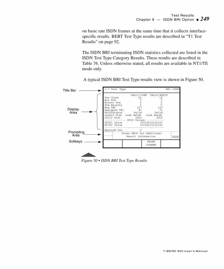
Test ResultsChapter 9 — ISDN BRI Option 249
T-BERD 950 User ’s Manual
on basic rate ISDN frames at the same time that it collects interface-specific results. BERT Test Type results are described in “T1 Test Results” on page 92.
The ISDN BRI terminating ISDN statistics collected are listed in the ISDN Test Type Category Results. These results are described in Table 76. Unless otherwise stated, all results are available in NT1/TE mode only.
A typical ISDN BRI Test Type results view is shown in Figure 50.
Figure 50 • ISDN BRI Test Type Results
Title Bar
DisplayArea
CALL1/LINE CALL2/EQUIPFrm Count 52 12Err Frm 0 0Reject Frm 0 0Frm Rejects 0 0Req TEI 127 127Assigned TEI 81 72SPID2Status Valid ValidLayer2 Stat Link Estab Link EstabCall2 Stat Idle Idle------------- SPID Values -----------SPID1 Value 30155512120100SPID2 Value 30155512130100-------------------------------------Aborted Frm 0
Prompting
Softkeys
3:7 Test Type BRI-ISDN
PGDN
Press HELP for Additional Result Information.
PRINTSCREEN
Area

Test Results250 Chapter 9 — ISDN BRI Option
T-BERD 950 User ’s Manual
Table 76 • ISDN BRI Test Type Category Result s
Result Description
Frm Count Counts the valid ISDN frames detected in circuit operation mode.
Err Frm Counts the errored frames with at least one of the following conditions: undefined control field, S or U frame with an improper length, and an I frame with a length exceeding limit.
Reject Frm Counts the frames with a sequence number error.
Frm Rejects Counts the frames with ISDN Frame Reject frames. A Frame Reject is sent when a device receives a frame with a protocol error.
Req TEI Displays the TEI that was requested. This is the value of the TEI request configuration.
Assigned TEI Displays the TEI that was assigned. This may or may not be equal to the requested TEI value.
SPID Status Displays the SPID status. This result can have the values: Valid, Invalid, Unassigned.
Layer2 Stat Displays the Layer 2 Status. Status messages are: TEI Not Assigned, Awaiting TEI, Link Not Established, Awaiting Establishment, Link Established, Timer Recovery, Awaiting Release, TEI Denied, Link Unknown.If the status is Link Not Established, a flashing two-line message on Results I and/or Results II indicates calls that cannot be placed.
Call Stat Displays the current call State.
SPID1 Value Displays the SPID value for Call 1 that was assigned during SPID assignment. Use in NT1 and LT modes also.
SPID2 Value Displays the SPID value for Call 2 that was assigned during SPID assignment. Use in NT1 and LT modes also.
Aborted Frm Counts the aborted ISDN frames detected, excluding Out of Frame aborts.

Test ResultsChapter 9 — ISDN BRI Option 251
T-BERD 950 User ’s Manual
Figure 51 shows a Typical ISDN call status and call failure report.
Invalid Frm Counts the frames with at least one of the following invalid conditions: short frame, FCS errored frame, single octet address, unapproved Service Access Point Identifier (SAPI).
Call Fails Counts the number of call attempts that ended in call failure (does not include busy replies or normal call clears).
Call 1 and Call 2 Status
Call Status — Displays current call status.Call Type — Displays DATA or VOICE call type.Caller ID — Displays the number from where the call is being placed.Channel # — Displays the Bearer Channel being used by the call.
Cause Codea — Displays the plain English text for the Cause Code.Location — Displays the location of the Cause Code.
Call Failure Report
Displays the status of the last 5 failed ISDN calls.Call Type — Displays DATA or VOICE call type.Channel # — Displays the Bearer Channel being used by the call.Cause Code — Displays the plain English text for the Cause Code.Location — Displays the location of the Cause Code.Calling # — Displays the number from where the call is being placed.Called # — Displays the number to where the call is being placed.
a. The analyzer interprets the Cause code for you; however, a complete list of Cause Codes can be found in Table 78, on page 256,
Table 76 • ISDN BRI Test Type Category Results (Continued)
Result Description
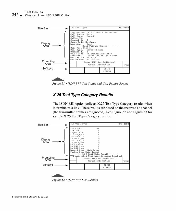
Test Results252 Chapter 9 — ISDN BRI Option
T-BERD 950 User ’s Manual
Figure 51 • ISDN BRI Call Status and Call Failure Report
X.25 Test Type Category Results
The ISDN BRI option collects X.25 Test Type Category results when it terminates a link. These results are based on the received D-channel (the transmitted frames are ignored). See Figure 52 and Figure 53 for sample X.25 Test Type Category results.
Figure 52 • ISDN BRI X.25 Results
Title Bar
DisplayArea
------------ Call 2 Status ----------Call Status: IdleCall Type: SpeechCaller ID:Channel #: 0Cause Code: No CauseLocation: User--------- Call Failure Report --------Call Fail Item 1Call Type: Unres 64 kbpsChannel #: 1Cause Code: No Channel AvailableLocation: Public Net to Local UserCalling Num: 5551212Called Num: 3015552525
Prompting
Softkeys
3:7 Test Type BRI-ISDN
PGDN
Press HELP for Additional Result Information.
PRINTSCREEN
Area
Title Bar
DisplayArea
Frm Count 59Err Frm 0Reject Frm 0Frm Rejects 0Tot Rx Pkts 2Rx Data Pkt 0Tot Tx Pkts 2Tx Data Pkt 0Rx RR Pkts 0Rx RNR Pkts 0Rx REJ Pkts 0Layer2 Stat Link EstabPacket Stat Data Transf-------- X.25 Call Data Result ------TPI Automated Test Line Entering Loopback
Prompting
Softkeys
3:7 Test Type BRI-ISDN
PGDN
Press HELP for Additional Result Information.
PRINTSCREEN
Area

Test ResultsChapter 9 — ISDN BRI Option 253
T-BERD 950 User ’s Manual
Figure 53 • ISDN BRI X.25 Call Results
The mainframe collects statistics on basic rate ISDN frames at the same time that it collects interface-specific results. These results are described in Table 77.
Table 77 • ISDN BRI X.25 Test Type Category Results
Result Description
Frm Count Counts the valid ISDN frames detected.
Err FrmCounts the errored frames with at least one of the following conditions: undefined control field, S or U frame with an improper length, and an I frame with a length exceeding limit.
Reject Frm Counts the frames with a sequence number error.
Frm RejectsCounts the frames with ISDN Frame Reject frames. A Frame Reject is sent when a device receives a frame with a protocol error.
Tot Rx Pkts Counts the total number of X.25 packets received.
Rx Data Pkt Counts the received data packets.
Title Bar
DisplayArea
---------- X.25 Call Result ---------Call Status: Data TransferLCN #: 1Cause Code: No CauseLocation: UserDiagnostic: No Addtional InfoReverse Chg: OFFCalling Num: 13015551212Called Num: 13015552525--------- Call Failure Report -------Call Fail Item 1LCN #: 5Cause Code: No CauseLocation: UserDiagnostic: Packet on Unassigned LCN
Prompting
Softkeys
3:7 Test Type BRI-ISDN
PGDN
Press HELP for Additional Result Information.
PRINTSCREEN
Area
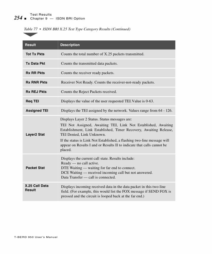
Test Results254 Chapter 9 — ISDN BRI Option
T-BERD 950 User ’s Manual
Tot Tx Pkts Counts the total number of X.25 packets transmitted.
Tx Data Pkt Counts the transmitted data packets.
Rx RR Pkts Counts the receiver ready packets.
Rx RNR Pkts Receiver Not Ready. Counts the receiver-not-ready packets.
Rx REJ Pkts Counts the Reject Packets received.
Req TEI Displays the value of the user requested TEI. Value is 0-63.
Assigned TEI Displays the TEI assigned by the network. Values range from 64 - 126.
Layer2 Stat
Displays Layer 2 Status. Status messages are:
TEI Not Assigned, Awaiting TEI, Link Not Established, AwaitingEstablishment, Link Established, Timer Recovery, Awaiting Release,TEI Denied, Link Unknown.
If the status is Link Not Established, a flashing two-line message will appear on Results I and or Results II to indicate that calls cannot be placed.
Packet Stat
Displays the current call state. Results include: Ready — no call active.DTE Waiting — waiting for far end to connect.DCE Waiting — received incoming call but not answered.Data Transfer — call is connected.
X.25 Call Data Result
Displays incoming received data in the data packet in this two-line field. (For example, this would list the FOX message if SEND FOX is pressed and the circuit is looped back at the far end.)
Table 77 • ISDN BRI X.25 Test Type Category Results (Continued)
Result Description
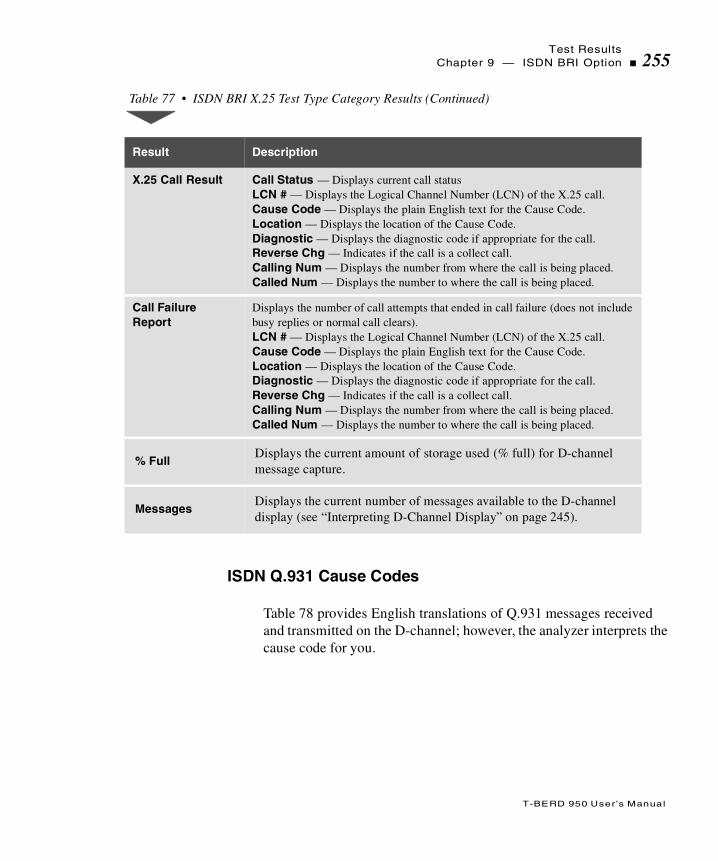
Test ResultsChapter 9 — ISDN BRI Option 255
T-BERD 950 User ’s Manual
ISDN Q.931 Cause Codes
Table 78 provides English translations of Q.931 messages received and transmitted on the D-channel; however, the analyzer interprets the cause code for you.
X.25 Call Result Call Status — Displays current call statusLCN # — Displays the Logical Channel Number (LCN) of the X.25 call.Cause Code — Displays the plain English text for the Cause Code.Location — Displays the location of the Cause Code.Diagnostic — Displays the diagnostic code if appropriate for the call.Reverse Chg — Indicates if the call is a collect call.Calling Num — Displays the number from where the call is being placed.Called Num — Displays the number to where the call is being placed.
Call Failure Report
Displays the number of call attempts that ended in call failure (does not include busy replies or normal call clears).LCN # — Displays the Logical Channel Number (LCN) of the X.25 call.Cause Code — Displays the plain English text for the Cause Code.Location — Displays the location of the Cause Code.Diagnostic — Displays the diagnostic code if appropriate for the call.Reverse Chg — Indicates if the call is a collect call.Calling Num — Displays the number from where the call is being placed.Called Num — Displays the number to where the call is being placed.
% FullDisplays the current amount of storage used (% full) for D-channel message capture.
MessagesDisplays the current number of messages available to the D-channel display (see “Interpreting D-Channel Display” on page 245).
Table 77 • ISDN BRI X.25 Test Type Category Results (Continued)
Result Description

Test Results256 Chapter 9 — ISDN BRI Option
T-BERD 950 User ’s Manual
Table 78 • ISDN BRI Results Reports Q.931 Cause Codes
Class Value No. Cause Code
— Q.931 Cause Codes (1988) —
000 00010010001101100111
12367
Unassigned number.No route to specified transit network.No route to destination.Channel unacceptable.Call awarded and being delivered in an established channel.
001 000000010010011101010110101010111100110111101111
161718192122262728293031
Normal call clearing.User busy.No user responding.No answer from user (user alerted).Call rejected.Number changed.Non-selected user clearing.Destination out of order.Invalid number format.Facility rejected.Response to STATUS INQUIRY.Normal, unspecified.
010 0001011010011010101111001111
34384142434447
No circuit/channel available.Network out of order.Temporary failure.Switching equipment congestion.Access information discarded.Requested circuit/channel not available.Resources unavailable, unspecified.
011 000100100110100110101111
495054575863
Quality of service unavailable.Requested facility not subscribed.Incoming calls barredBearer capability not authorized.Bearer capability not presently available.Service or option not available, unspecified.

Test ResultsChapter 9 — ISDN BRI Option 257
T-BERD 950 User ’s Manual
100 0001001001010110
1111
65666970
79
Bearer capability not implemented.Change type not implemented.Requested facility not implemented.Only restricted digital information bearer capability is available.Service or option not implemented, unspecified.
101 000100100011
010001010110100010111111
818283
848586889195
Invalid call reference value.Identified channel does not exist.A suspended call exists, but this call identity does not exist.Call identity in use.No call suspended.Call having the requested call identity has been cleared.Incompatible destination.Invalid transit network selection.Invalid message, unspecified.
110 000000010010
00110100010101101111
969798
99100101102111
Mandatory information element is missing.Message type nonexistent or not implemented.Message not compatible with call state or message type nonexistent or not implemented.Information element nonexistent or not implemented.Invalid information element contents.Message not compatible with call state.Recovery on timer expired.Protocol error, unspecified.
111 1111 127 Interworking, unspecified.
— National-specific Cause Codes Defined in TA-NWT-001268 —
000 01001000100110101011
4891011
Vacant code.Prefix 0 dialed in error.Prefix 1 dialed in error.Prefix 1 not dialed.Excessive digits received, call is proceeding.
110 0101 101 Protocol error, threshold exceeded.
Table 78 • ISDN BRI Results Reports Q.931 Cause Codes (Continued)
Class Value No. Cause Code

Test Results258 Chapter 9 — ISDN BRI Option
T-BERD 950 User ’s Manual

T
T-BERD 950 User ’s Manual
his section provides step-by-step instructions for using the 10BaseT/Ethernet option for the T-BERD 950 and discusses the following
topics:
Option Description
TNT Test Setup
Manual Test Setup
Test Results
10 BaseT/Ethernet Option
Option Description260 Chapter 9 — 10 BaseT/Ethernet Option
T-BERD 950 User ’s Manual
Option Description
The 10BaseT option enables the T-BERD 950 Communications Analyzer to perform the following:
PING testing
IP traffic generation
Operating Modes
Terminate mode is the only available operating mode for the 10BaseT option. After the TB-950 detects a valid Ethernet signal, it is ready to perform the required tests (PING or Load Generation).
You can configure the 10BaseT option for static or dynamic IP addresses. Dynamic addresses should be selected for Dynamic Host Control Protocol (DHCP) network implementations. In this case, the T-BERD 950 is assigned an IP address by the DHCP server.
PING Testing
The 10BaseT option provides the ability to verify network connectivity by transmitting and responding to Internet Control Message Protocol (ICMP) Echo requests (PING) between the customer premises and other points within the network, such as a server or router located at the CO, POP, or NOC. PING testing verifies that connectivity has been established and provides a basic measure of expected network performance. PING testing allows you to isolate faulty or misoptioned equipment and identify network congestion problems.
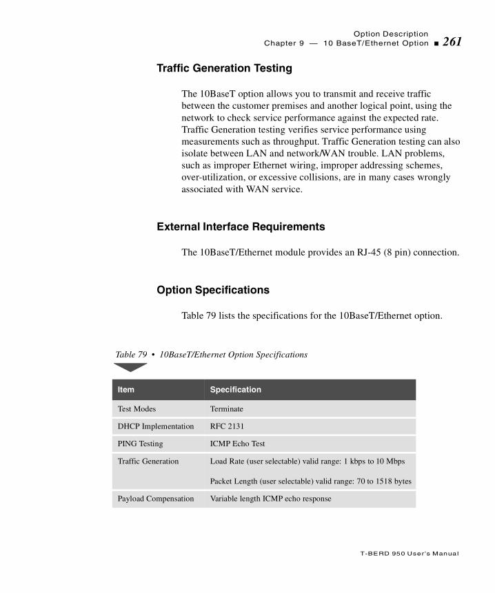
Option DescriptionChapter 9 — 10 BaseT/Ethernet Option 261
T-BERD 950 User ’s Manual
Traffic Generation Testing
The 10BaseT option allows you to transmit and receive traffic between the customer premises and another logical point, using the network to check service performance against the expected rate. Traffic Generation testing verifies service performance using measurements such as throughput. Traffic Generation testing can also isolate between LAN and network/WAN trouble. LAN problems, such as improper Ethernet wiring, improper addressing schemes, over-utilization, or excessive collisions, are in many cases wrongly associated with WAN service.
External Interface Requirements
The 10BaseT/Ethernet module provides an RJ-45 (8 pin) connection.
Option Specifications
Table 79 lists the specifications for the 10BaseT/Ethernet option.
Table 79 • 10BaseT/Ethernet Option Specifications
Item Specification
Test Modes Terminate
DHCP Implementation RFC 2131
PING Testing ICMP Echo Test
Traffic Generation Load Rate (user selectable) valid range: 1 kbps to 10 Mbps
Packet Length (user selectable) valid range: 70 to 1518 bytes
Payload Compensation Variable length ICMP echo response

Setting up TNT Testing262 Chapter 9 — 10 BaseT/Ethernet Option
T-BERD 950 User ’s Manual
Setting up TNT Testing
This section describes the TNT test setups for the 10BaseT/Ethernet option. A sample TNT Setup view is shown in Figure 54.
Figure 54 • 10BaseT TNT Setup View
Table 80 lists the TNT test setup for performing 10BaseT/Ethernet Turn-up tasks. For descriptions of the test setup parameters, see “Setting up Manual Testing” on page 263. For descriptions of all results, see “Test Results” on page 266.
Title Bar
SelectionArea
IP Address Mode: StaticSource IP Address: 1. 1. 1. 1Gateway Address: 1. 1. 1. 2Subnet Mask: 255.255.255. 0Dest IP Address: 1. 1. 1. 3
Prompting
Softkeys
3:3 TNT 10BaseT PING
FUNC
MORE
Select IP Address Mode
DynamicStatic
Area
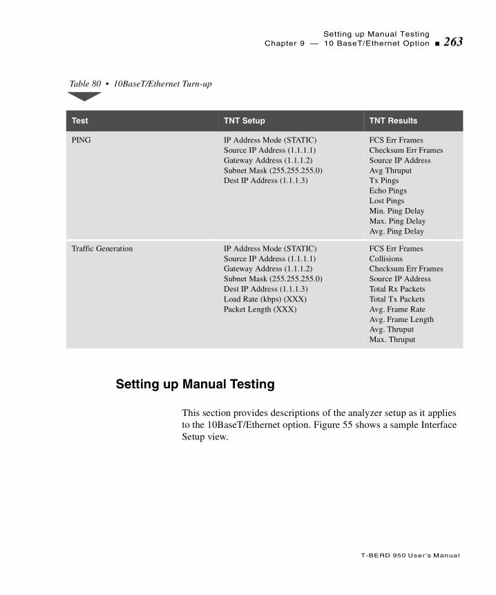
Setting up Manual TestingChapter 9 — 10 BaseT/Ethernet Option 263
T-BERD 950 User ’s Manual
Setting up Manual Testing
This section provides descriptions of the analyzer setup as it applies to the 10BaseT/Ethernet option. Figure 55 shows a sample Interface Setup view.
Table 80 • 10BaseT/Ethernet Turn-up
Test TNT Setup TNT Results
PING IP Address Mode (STATIC)Source IP Address (1.1.1.1)Gateway Address (1.1.1.2)Subnet Mask (255.255.255.0)Dest IP Address (1.1.1.3)
FCS Err FramesChecksum Err FramesSource IP AddressAvg ThruputTx PingsEcho PingsLost PingsMin. Ping DelayMax. Ping DelayAvg. Ping Delay
Traffic Generation IP Address Mode (STATIC)Source IP Address (1.1.1.1)Gateway Address (1.1.1.2)Subnet Mask (255.255.255.0)Dest IP Address (1.1.1.3)Load Rate (kbps) (XXX)Packet Length (XXX)
FCS Err FramesCollisionsChecksum Err FramesSource IP AddressTotal Rx PacketsTotal Tx PacketsAvg. Frame RateAvg. Frame LengthAvg. ThruputMax. Thruput

Setting up Manual Testing264 Chapter 9 — 10 BaseT/Ethernet Option
T-BERD 950 User ’s Manual
Figure 55 • 10BaseT Setup Interface View
Setting up the Interface View
The Interface Setup view configures the 10BaseT/Ethernet interface. Currently, only the Terminate interface is available for the 10BaseT/Ethernet option.
Mode — Enables selection of the operating mode. Only TERMINATE is available (see “Operating Modes” on page 260).
Setting up the Test Type View
The Test Type Setup view configures the test to be performed. The SCROLL key controls this selection area. Figure 56 shows a sample Test Type Setup view.
Title Bar
SelectionArea
Mode: TERMINATE
Prompting
Softkeys
1:2 Interface 10BaseT - IP
FUNC Select Mode:
TERMINATE
Area

Setting up Manual TestingChapter 9 — 10 BaseT/Ethernet Option 265
T-BERD 950 User ’s Manual
Figure 56 • 10BaseT Setup Test Type View
IP Address Mode — Select the IP Address Mode as DYNAMIC or STATIC.
DYNAMIC — Configures the T-BERD 950 to accept an IP address that is assigned dynamically by the server using DHCP.
STATIC —Allows you to enter the specified source IP address for the device or location at which testing is conducted.
Source IP Address — (STATIC). Enables you to specify the source IP address. Use the keypad to enter the address in this format: xxx.xxx.xxx.xxx. (Leading zeros are deleted from the IP address when you exit this field.) Address entries of 0.0.0.0 or 255.255.255.255 are not valid.
Gateway Address — (STATIC). Enables you to specify the gateway address. Use the keypad to enter the address in this format: xxx.xxx.xxx.xxx. (Leading zeros are deleted from the IP address when you exit this field.) Address entries of 0.0.0.0 or 255.255.255.255 are not valid.
Title Bar
SelectionArea
IP Address Mode: StaticSource IP Address: 1. 1. 1. 1Gateway Address: 1. 1. 1. 2Subnet Mask: 255.255.255. 0Transmit Load: TrafficDestination Address: 1. 1. 1. 3Load Rate (kbps): 144Packet Length: 493
Prompting
Softkeys
2:2 Test Type 10BaseT - IP
FUNC Select Mode:
DynamicStatic
Area
Test Results266 Chapter 9 — 10 BaseT/Ethernet Option
T-BERD 950 User ’s Manual
Subnet Mask — (STATIC). Enables you to specify the subnet mask address. Use the keypad to enter the address in this format: xxx.xxx.xxx.xxx. (Leading zeros are deleted from the IP address when you exit this field.)
Transmit Load — Select the Transmit Mode as OFF, PING, or TRAFFIC.
OFF — No transmit load is selected.
PING — Allows you to perform PING testing.
TRAFFIC — Allows you to perform Traffic Generation testing.
Dest IP Address — Enables entry of the destination IP address, format is xxx.xxx.xxx.xxx. Use the keypad to enter the address. (Leading zeros are deleted from the IP address when you exit this field). Address entries of 0.0.0.0 or 255.255.255.255 are not valid.
Load Rate (kbps) — (TRAFFIC). Enables you to specify the load rate. Use the keypad or INCREASE VALUE or DECREASE VALUE softkeys to set the level. Valid entry ranges 1 Kbps to 10 Mbps.
Packet Length — (TRAFFIC). Enables you to specify the packet length in bytes. Use the keypad or INCREASE VALUE or DECREASE VALUE softkeys to set the level. Valid entry ranges from 70 to 1518 bytes.
Test Results
Test results for the 10BaseT option appear on the analyzer Two-Line Display. The Two-Line Display and associated controls and indicators are located on the front panel above the keypad. For a detailed description of the Two-Line Display, see “Test Results Display” on
Example: A subnet mask of 255.255.255.252 limits the number of devices (unique IP addresses) on that subnet to four.

Test ResultsChapter 9 — 10 BaseT/Ethernet Option 267
T-BERD 950 User ’s Manual
page 90. Test results are also shown on the Large Graphical Display Results view. For a detailed description of the Large Graphical Display, see “Results View” on page 33. A typical 10BaseT Results view is shown in Figure 57.
Figure 57 • 10BaseT Results Test Type View
Status and Alarm LEDs
The 10BaseT/Ethernet option uses the mainframe Status and Alarm LEDs. Depending on the interface or option in use, these LEDs have alternate meanings. Table 81 describes the LEDs used for the 10BaseT/Ethernet option.
Title Bar
SelectionArea
Rx Frm CntRx OctetsTx OctetsAvg Frm LenSrcAdrGateway AddressSubnet MaskRx IP PacktTx IP PacktRx Cksm ErrLost PingsTx PingsEcho Pings
Prompting
Softkeys
3:7 Test Type 10BaseT - IP
FUNC Press HELP for AdditionalResult Information
PRINTSCREEN
Area

Test Results268 Chapter 9 — 10 BaseT/Ethernet Option
T-BERD 950 User ’s Manual
Summary Category Results
The Summary category automatically lists key results that are out of specification. If all results are within specification for the LINE or EQUIPMENT receiver, the message All Results OK appears on the appropriate side of the Two-Line Display.
Interface Category Results
The Interface Category results are described in Table 82.
Table 81 • Status and Alarm LEDs
LED Description
SIGNAL(Description)
Illuminates green to indicate that the Ethernet Link is detected.
FRAME SYNC(Receiver Status)
Illuminates green to indicate that the T-BERD 950 is receiving a Ethernet data.
YELLOW ALARM(Collision Detection)
Illuminates when an Ethernet Collision is detected.
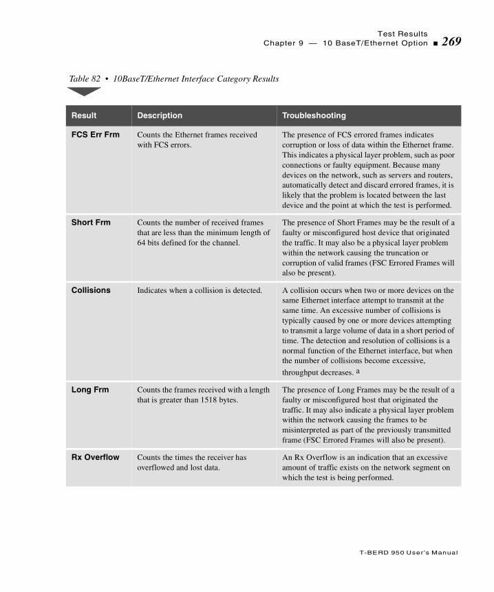
Test ResultsChapter 9 — 10 BaseT/Ethernet Option 269
T-BERD 950 User ’s Manual
Table 82 • 10BaseT/Ethernet Interface Category Results
Result Description Troubleshooting
FCS Err Frm Counts the Ethernet frames received with FCS errors.
The presence of FCS errored frames indicates corruption or loss of data within the Ethernet frame. This indicates a physical layer problem, such as poor connections or faulty equipment. Because many devices on the network, such as servers and routers, automatically detect and discard errored frames, it is likely that the problem is located between the last device and the point at which the test is performed.
Short Frm Counts the number of received frames that are less than the minimum length of 64 bits defined for the channel.
The presence of Short Frames may be the result of a faulty or misconfigured host device that originated the traffic. It may also be a physical layer problem within the network causing the truncation or corruption of valid frames (FSC Errored Frames will also be present).
Collisions Indicates when a collision is detected. A collision occurs when two or more devices on the same Ethernet interface attempt to transmit at the same time. An excessive number of collisions is typically caused by one or more devices attempting to transmit a large volume of data in a short period of time. The detection and resolution of collisions is a normal function of the Ethernet interface, but when the number of collisions become excessive,
throughput decreases. a
Long Frm Counts the frames received with a length that is greater than 1518 bytes.
The presence of Long Frames may be the result of a faulty or misconfigured host that originated the traffic. It may also indicate a physical layer problem within the network causing the frames to be misinterpreted as part of the previously transmitted frame (FSC Errored Frames will also be present).
Rx Overflow Counts the times the receiver has overflowed and lost data.
An Rx Overflow is an indication that an excessive amount of traffic exists on the network segment on which the test is being performed.
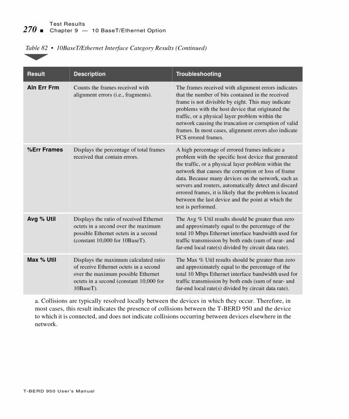
Test Results270 Chapter 9 — 10 BaseT/Ethernet Option
T-BERD 950 User ’s Manual
Aln Err Frm Counts the frames received with alignment errors (i.e., fragments).
The frames received with alignment errors indicates that the number of bits contained in the received frame is not divisible by eight. This may indicate problems with the host device that originated the traffic, or a physical layer problem within the network causing the truncation or corruption of valid frames. In most cases, alignment errors also indicate FCS errored frames.
%Err Frames Displays the percentage of total frames received that contain errors.
A high percentage of errored frames indicate a problem with the specific host device that generated the traffic, or a physical layer problem within the network that causes the corruption or loss of frame data. Because many devices on the network, such as servers and routers, automatically detect and discard errored frames, it is likely that the problem is located between the last device and the point at which the test is performed.
Avg % Util Displays the ratio of received Ethernet octets in a second over the maximum possible Ethernet octets in a second (constant 10,000 for 10BaseT).
The Avg % Util results should be greater than zero and approximately equal to the percentage of the total 10 Mbps Ethernet interface bandwidth used for traffic transmission by both ends (sum of near- and far-end local rate(s) divided by circuit data rate).
Max % Util Displays the maximum calculated ratio of receive Ethernet octets in a second over the maximum possible Ethernet octets in a second (constant 10,000 for 10BaseT).
The Max % Util results should be greater than zero and approximately equal to the percentage of the total 10 Mbps Ethernet interface bandwidth used for traffic transmission by both ends (sum of near- and far-end local rate(s) divided by circuit data rate).
a. Collisions are typically resolved locally between the devices in which they occur. Therefore, inmost cases, this result indicates the presence of collisions between the T-BERD 950 and the deviceto which it is connected, and does not indicate collisions occurring between devices elsewhere in thenetwork.
Table 82 • 10BaseT/Ethernet Interface Category Results (Continued)
Result Description Troubleshooting
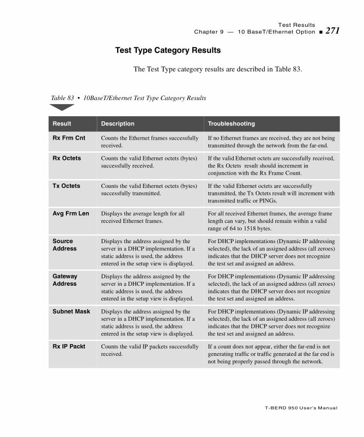
Test ResultsChapter 9 — 10 BaseT/Ethernet Option 271
T-BERD 950 User ’s Manual
Test Type Category Results
The Test Type category results are described in Table 83.
Table 83 • 10BaseT/Ethernet Test Type Category Results
Result Description Troubleshooting
Rx Frm Cnt Counts the Ethernet frames successfully received.
If no Ethernet frames are received, they are not being transmitted through the network from the far-end.
Rx Octets Counts the valid Ethernet octets (bytes) successfully received.
If the valid Ethernet octets are successfully received, the Rx Octets result should increment in conjunction with the Rx Frame Count.
Tx Octets Counts the valid Ethernet octets (bytes) successfully transmitted.
If the valid Ethernet octets are successfully transmitted, the Tx Octets result will increment with transmitted traffic or PINGs.
Avg Frm Len Displays the average length for all received Ethernet frames.
For all received Ethernet frames, the average frame length can vary, but should remain within a valid range of 64 to 1518 bytes.
Source Address
Displays the address assigned by the server in a DHCP implementation. If a static address is used, the address entered in the setup view is displayed.
For DHCP implementations (Dynamic IP addressing selected), the lack of an assigned address (all zeroes) indicates that the DHCP server does not recognize the test set and assigned an address.
Gateway Address
Displays the address assigned by the server in a DHCP implementation. If a static address is used, the address entered in the setup view is displayed.
For DHCP implementations (Dynamic IP addressing selected), the lack of an assigned address (all zeroes) indicates that the DHCP server does not recognize the test set and assigned an address.
Subnet Mask Displays the address assigned by the server in a DHCP implementation. If a static address is used, the address entered in the setup view is displayed.
For DHCP implementations (Dynamic IP addressing selected), the lack of an assigned address (all zeroes) indicates that the DHCP server does not recognize the test set and assigned an address.
Rx IP Packt Counts the valid IP packets successfully received.
If a count does not appear, either the far-end is not generating traffic or traffic generated at the far end is not being properly passed through the network.

Test Results272 Chapter 9 — 10 BaseT/Ethernet Option
T-BERD 950 User ’s Manual
Tx IP Packt Counts the valid IP packets successfully transmitted.
If a count does not appear, IP traffic is not being transmitted through the network.
Rx Cksm Err Counts the IP packets received with checksum errors.
If and IP packet is received that contains a checksum error, this can indicate a problem. The problem may be with the host device that originates the traffic, or a physical layer problem causing the IP packet data corruption or loss. Because most routers that handle Layer 3 routing discard packets with checksum errors, it is likely that the problem is located between the last device and the point at which the test is performed.
Lost Pings Counts the transmitted PINGs that have timed out waiting for a response. (Echo replies that are not received within 5 seconds of the transmission of an echo request (PING) are declared lost.)
If an excessive number of lost PINGs occurs, but some echo replies are received from the far-end device, network congestion is most likely the source of the problem. If no echo replies are received from the far-end device, then the addressing may be incorrect or a problem with the device itself may exist.
Tx Pings Counts the transmitted PINGs. If a count does not appear, the T-BERD 950 is not transmitting PING Packets.
Echo Pings Counts the transmitted PING responses. If a count does not appear, the far-end device may not be sending PING packets successfully to the T-BERD 950.
Table 83 • 10BaseT/Ethernet Test Type Category Results (Continued)
Result Description Troubleshooting

Test ResultsChapter 9 — 10 BaseT/Ethernet Option 273
T-BERD 950 User ’s Manual
Performance Category Results
Performance category results are described in Table 84.
Table 84 • 10BaseT/Ethernet Performance Category Results
Result Description Troubleshooting
Avg Frm Rat Displays the average rate in frames per second for all transmitted and received Ethernet frames.
The average frame ratio should increment in correspondence to traffic generated and received. If the results do not correspond, Ethernet frames are not being transmitted or received.
Avg Thruput Displays the ratio of Ethernet octets over elapsed time (in Kbps).
The average throughput should correspond to the rate being transmitted. (Assuming this fixed rate is below the maximum near-end circuit data rate.)
Max Thruput Displays the maximum calculated ratio of Ethernet octets over elapsed time (in Kbps).
The maximum throughput should correspond to the rate being transmitted. (Assuming this fixed rate is below the maximum near-end circuit data rate.)
Min Png Dly Displays the minimum time taken for a PING echo packet to be transmitted and an echo reply received (in msec).
The difference between minimum, average, and maximum PING delay provides a baseline measure of network performance. This occurs when a series of PINGs are transmitted over a period of time. Excessive delays are typically caused by congestion at some point on the network. By sending PINGs to devices located at different points within the network, areas of congestion can be isolated.
Max Png Dly Displays the maximum time taken for a PING echo packet to be transmitted and an echo reply received (in msec).
Avg Png Dly Displays the average time taken for the PING echo packet to be transmitted and an echo reply received (in msec).

Test Results274 Chapter 9 — 10 BaseT/Ethernet Option
T-BERD 950 User ’s Manual

T
T-BERD 950 User ’s Guide
his chapter describes services, service locations, and available training through Acterna (formerly TTC and WWG). Both warranty and out-
of-service warranty service information is provided.
Chap te r10 Acterna
Customer Services

T-BERD 950 User ’s Guide
Overview276 Chapter 10 — Acterna Customer Services
Overview
Acterna offers unmatched services to support purchased equipment, including a wide range of customer care, technical support, instrument maintenance, and training services. Acterna customer service specialists are fully trained to help customers find the answers they are looking for. Call Customer Services for:
Information on products and services, including upgrades, calibration, training, software enhancement agreements (SEAs), and product maintenance agreements. Our representatives can also provide assistance with product returns and repairs.
Expert technical support, including help with product configuration, circuit qualification, and complete network trouble sectionalization. Acterna is also available on a contractual basis to provide customized application development, network consulting and management services, software customization, and test procedure development.
All Acterna products are backed by an industry-leading warranty that guarantees mainframe repair or replacement for 3 years and all other parts for 1 year.
Customer Service Locations
For questions regarding Acterna products and services, including return authorizations and repairs, technical support, training, and all other available services, contact your local distributor or Acterna Customer Service at one of the locations listed in the Acterna Contact list at the beginning of this manual.

T-BERD 950 User ’s Guide
ServicesChapter 10 — Acterna Customer Services 277
Services
Instrument Service
To maintain your organization’s long-term investment, Acterna will structure a service plan to fit your network performance goals and budget. Acterna understands the impact of equipment down time on operations and is staffed to ensure a quick turnaround. Available services include:
Product Repair — All equipment returned for service is tested to the same rigorous standards as newly manufactured equipment. This ensures products meet all published specifications, including any applicable product updates.
Calibration — Acterna’s calibration methods are ISO 9001 approved and based on NIST standards. Each calibration comes with a dated certificate, instrument stickers, and a data sheet.
Factory Upgrades — Any unit returned for a hardware feature enhancement will also receive applicable product updates and will be thoroughly tested, ensuring peak performance of the com-plete feature set.
Software Enhancement Agreements — These agreements assist in keeping equipment up to date with the latest software features, by providing automatic notification of any new software enhancements and changes for Acterna products.
Product Maintenance Agreements — Yearly service and cali-bration maintenance agreements simplify billing and help ensure the equipment is always operating at optimum levels. Product maintenance agreements can be used to extend a current warranty or provide protection for out-of-warranty units.
Other Pricing Options — For out-of-warranty repairs, Acterna offers two additional pricing options: time and material pricing and flat rate pricing. Under time and material pricing, customers are billed for the actual cost of the repair, making this a cost-effective method for minor repairs. Under flat rate pricing, cus-

T-BERD 950 User ’s Guide
Services278 Chapter 10 — Acterna Customer Services
tomers pay a fixed service charge to repair unit failures (exclud-ing damage or abuse), resulting in simplified paperwork and easier budgeting.
Product Enhancement Group
The Product Enhancement Group staff offers one of the broadest and most experienced resource portfolios in the communications testing industry. This team of professionals offers expertise in software development, test procedure development, and network consulting, as well as years of expert test knowledge. Support is available for all core Acterna product lines:
Network Consulting and Management — Provides services such as productivity analysis, test strategy assessment, on-site applications assistance, and specialized training.
Software Customization — Develops scripts for remote and automated testing, statistics, and emulation.
Test Procedure Development — Creates procedures for auto-mated testing, network testing, and compliance testing.
Test Systems Field Engineering and Installation
Acterna offers a range of support services for our centralized test systems, designed around the needs of the customer’s network. These services help preserve the investment over the life of the equipment. Available services include:
Critical Services Program — Provides technical support at any time, 7 days a week, 24 hours a day. Replacement parts are guar-anteed to arrive within 48 hours of contacting Acterna.
Maintenance Contracts — Cost-effective management for net-works with multiple test systems.

T-BERD 950 User ’s Guide
ServicesChapter 10 — Acterna Customer Services 279
Out-of-Warranty Service Agreement — Covers the test system for failures after the warranty expires, including all time and material costs and return shipping costs to the customer site.
Field Engineering and Installation Service — Provides a vari-ety of options for implementing the test system into the network, including installation, configuration, upgrades, and on-site tech-nical support.
Technical Training
By providing both experienced instructors and a hands-on atmosphere, Acterna training is designed to optimize test strategies and employee development requirements. Available services include:
Customized Technical Training — Designed to incorporate real-life challenges technicians face daily, while addressing the customer’s training requirements, Acterna provides training at the customer’s designated site, so the whole staff is trained at one time. Step-by-step reviews of current technologies and products enable new or experienced technicians to translate theory into practical, hands-on expertise.
Public Courses — Regularly scheduled, in-depth, hands-on product and technology courses are offered worldwide. Public courses provide a learning environment that allows individuals from different companies to share their knowledge and experi-ence with their peers.
Computer-Based Training (CBT) — Acterna’s CBT comple-ments our hands-on technical training. With CBT, customers can learn about emerging communications technologies at their own convenience — at work, at home, or while traveling. Acterna’s CBT courses cover technology topics such as ATM, frame relay, ISDN, LAN basics, and more.
Customized Multimedia Course Development — Multimedia courseware can be created to customer specifications, making it easier to learn new test instruments or applications. These custom
T-BERD 950 User ’s Guide
Warranty Information280 Chapter 10 — Acterna Customer Services
packages provide consistent educational content and training for the entire staff. Students learn at their own pace on their own PC.
Consulting and Needs Analysis Services — Acterna can help identify training needs and develop customized training curricula to maximize learning opportunities, all while providing a measur-able return on investment.
Warranty Information
The warranties described herein shall apply to all commercially available Acterna products. Any additional or different warranties shall apply only if agreed to by Acterna in writing. These warranties are not transferable without the express written consent of Acterna.
Hardware Warranty — Acterna warrants that Hardware Product sold to customer shall, under normal use and service, be free from defects in materials and workmanship. The warranty period shall be three (3) years for mainframes and options (parts and labor), and (1) one year for accessories and field-replaceable batteries. If installation services have been ordered, the warranty period shall begin on the earlier of (1) completion of installation, or (2) thirty (30) days after shipment to Customer. If Installation Services have not been ordered, the warranty period shall begin upon shipment to Customer. Hereafter these periods of time shall be collectively referred to as the “Initial Warranty Period.”
Acterna’s obligation and customer’s sole remedy under this Hardware Warranty is limited to the repair or replacement, at Acterna’s option, of the defective product. Acterna shall have no obligation to remedy any such defect if it can be shown: (a) that the Product was altered, repaired, or reworked by any party other than Acterna without Acterna’s written consent; (b) that such defects were the result of customer’s improper storage, mishandling, abuse, or misuse of Product; (c) that such defects were the result of customer’s use of Product in conjunction with equipment electronically or mechanically
T-BERD 950 User ’s Guide
Warranty InformationChapter 10 — Acterna Customer Services 281
incompatible or of an inferior quality; or (d) that the defect was the result of damage by fire, explosion, power failure, or any act of nature.
Acterna warrants that Products returned to Acterna for repair shall be warranted from defective materials and workmanship for one (1) year for the same repair issue, and ninety (90) days for a different repair issue from date of shipment from Acterna to customer, or until the end of the Initial Warranty Period, whichever is longer. Risk of loss or damage to Product returned to Acterna for repair or replacement shall be borne by customer until delivery to Acterna. Upon delivery of such product, Acterna shall assume the risk of loss or damage until that time that the product being repaired or replaced is returned and delivered to customer. Customer shall pay all transportation costs for equipment or software shipped to Acterna for repair or replacement. Acterna shall pay all transportation costs associated with returning repaired or replaced product to customer.
Software Warranty — Acterna warrants that Software Products licensed to Customer shall, under normal use and service, and for a period of ninety (90) days from the date of shipment of the Software to Licensee (the “Warranty Period”), perform in all material respects in accordance with the published specifications for such Software as established by Acterna. However, Acterna does not warrant that the Software will operate uninterrupted or error free, operate in the combination with other software, meet Customer’s requirements, or that its use will be uninterrupted.
Acterna’s obligation and Customer’s sole and exclusive remedy under this Software Warranty is limited to, at Acterna’s option, either (i) correcting the material errors reported to Acterna in writing by Customer during the Warranty Period and which Acterna is able to reproduce, (ii) replacing such defective Software, provided that Acterna received written notice of such defect within the Warranty Period, or (iii) provided that Acterna received written notice of such defect within the Warranty Period, terminating the License and, upon return to Acterna of the Software, Documentation and all other materials provided by Acterna under the applicable License,

T-BERD 950 User ’s Guide
Equipment Return Instructions282 Chapter 10 — Acterna Customer Services
providing Customer with a refund of all charges paid with respect thereto. Acterna shall have no warranty obligations hereunder if (a) the Software is altered or modified or is merged with other software by Customer or any third party or (b) all or any part of the Software is installed on any computer equipment other than the Designated Server or used with any operating system for which the Software is not designed.
Services Warranty — Acterna warrants that the Services provided by Acterna, if any, shall be performed promptly, diligently and in a professional manner in accordance with the commercial standards of the industry. Acterna shall not, however, be responsible for any delays that are not due to Acterna’s fault or negligence or that could not have reasonably been foreseen or provided against.
WARRANTY DISCLAIMER — FOR HARDWARE, SOFTWARE, AND/OR SERVICES FURNISHED BY ACTERNA, THE FOREGOING WARRANTEES ARE IN LIEU OF ALL OTHER WARRANTEES AND CONDITIONS, EXPRESS OR IMPLIED. ACTERNA SPECIFICALLY DISCLAIMS ALL OTHER WARRANTIES, EITHER EXPRESS OR IMPLIED, ON ANY HARDWARE, SOFTWARE, DOCUMENTATION OR SERVICES INCLUDING BUT NOT LIMITED TO WARRANTIES RELATING TO QUALITY, PERFORMANCE, NONINFRINGEMENT, MERCHANTABILITY OR FITNESS FOR A PARTICULAR PURPOSE, AS WELL AS THOSE ARISING FROM ANY COURSE OF DEALING, USAGE OR TRADE PRACTICE. UNDER NO CIRCUMSTANCES WILL ACTERNA BE LIABLE FOR ANY INDIRECT OR CONSEQUENTIAL DAMAGES RELATED TO BREACH OF THIS WARRANTY.
Equipment Return Instructions
For each piece of equipment returned for repair, attach a tag that includes the following information:
1. Owner’s name, address, and telephone number.
2. The serial number, product type, and model.

T-BERD 950 User ’s Guide
Equipment Return InstructionsChapter 10 — Acterna Customer Services 283
3. Warranty status. (If you are unsure of the warranty status of your instrument, contact Acterna Customer Service.)
4. A detailed description of the problem or service requested.
5. The name and telephone number of the person to contact regarding questions about the repair.
6. The return authorization (RA) number (US customers), or reference number (European Customers).
If possible, return the equipment using the original shipping container and material. If the original container is not available, the unit should be carefully packed so that it will not be damaged in transit; when needed, appropriate packing materials can be obtained by contacting Acterna Customer Services. Acterna is not liable for any damage that may occur during shipping. The customer should clearly mark the Acterna-issued RA or reference number on the outside of the package and ship it prepaid and insured to Acterna.

T-BERD 950 User ’s Guide
Equipment Return Instructions284 Chapter 10 — Acterna Customer Services

T
T-BERD 950 User ’s Guide
his appendix provides the loop code addresses by repeater and HDSL card type, the Repeater commands, and loop codes.
Append ixA Repeater Loop
Codes

T-BERD 950 User ’s Guide
286 Appendix A — Repeater Loop Codes
Teltrend Repeater Command Loop Codes are listed in Table 85.
Table 85 • Teltrend Repeater Command Loop Code s
Repeater Command Loop Code
7231 LP/LW IOR7239 LP/LW ILR9132 LP/LW IHR
Arm (Inband) 11000
Arm ESF Datalink 0001 0010 1111 1111
7231 LP/LW IOR7239 LP/LW ILR9132 LP/LW IHR
Disarm (Inband) 11100
Disarm ESF Datalink 0010 0100 1111 1111
7231 LP/LW IOR7239 LP/LW ILR9132 LP/LW IHR
Near End Arm 11000
7231 LP IOR7231 LW IOR9132 LP IHR
Loop Up 1101 0011 1101 0011
7231 LW IOR7231 LW IHR
Loop Up 1100 0101 0100 0001
7239 LP/LW ILR Loop Up 1100 0111 010A AAAA a
7231 LP/LW IOR7239 LP/LW ILR9132 LP/LW IHR
Loop Down 1001 0011 1001 0011
7231 LP/LW IOR7239 LP/LW ILR9132 LP/LW IHR
Loop BackTimeout Disable
1101 0101 1101 0110
7231 LP/LW IOR7239 LP/LW ILR9132 LP/LW IHR
Loop Back Query 1101 0101 1101 0101
7231 LP/LW IOR7239 LP/LW ILR9132 LP/LW IHR
Power Loop Query 0101 1011 0101 1011
7231 LP/LW IOR7239 LP/LW ILR9132 LP/LW IHR
Issues Query 0101 0110 1011 0111

T-BERD 950 User ’s Guide
Appendix A — Repeater Loop Codes 287
Westell Repeater Command Loop Codes are listed in Table 86.
7231 LP IOR9132 LP IHR
Power Down 0110 0111 0110 0111
7231 LW IOR9132 LW IHR
Power Down 0101 0110 1111 1011
7231 LP/LW IOR9132 LP/LW IHR
Power Up Removes Power Down Code
7231 LP/LW IOR7239 LP/LW ILR9132 LP/LW IHR
Sequential Loop Back 1100 0111 1101 0010
a. Replace the A in the loop code with the repeater address.
Table 86 • Westell Repeater Command Loop Codes
Repeater Command Loop Code
3130-80 IOR3150-80 ILR3150-81 ILR3150-56 ILR3151-56 ILR3130-56 IOR
Arm (Inband) 11000
Arm ESF Datalink 1111 0100 1000
3130-80 IOR3150-80 ILR3150-81 ILR3150-56 ILR3151-56 ILR3130-56 IOR
Disarm (Inband) 11100
Disarm ESF Datalink 1111 1111 0010 0100
3130-80 IOR Loop Up 1100 0AAA AAAA AAAA a
3150-80 ILR3150-81 ILR
Loop Up 1100 1AAA AAAA AAAA
Table 85 • Teltrend Repeater Command Loop Codes (Continued)
Repeater Command Loop Code
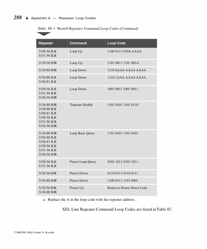
T-BERD 950 User ’s Guide
288 Appendix A — Repeater Loop Codes
XEL Line Repeater Command Loop Codes are listed in Table 87.
3150-56 ILR3151-56 ILR
Loop Up 1100 0111 010A AAAA
3130-56 IOR Loop Up 1101 0011 1101 001A
3130-80 IOR Loop Down 1110 0AAA AAAA AAAA
3150-80 ILR3150-81 ILR
Loop Down 1110 1AAA AAAA AAAA
3150-56 ILR3151-56 ILR3130-56 IOR
Loop Down 1001 0011 1001 0011
3130-80 IOR3150-80 ILR3150-81 ILR3150-56 ILR3151-56 ILR3130-56 IOR
Timeout Disable 1101 0101 1101 0110
3130-80 IOR3150-80 ILR3150-81 ILR3150-56 ILR3151-56 ILR3130-56 IOR
Loop Back Query 1101 0101 1101 0101
3150-56 ILR3151-56 ILR
Power Loop Query 0101 1011 0101 1011
3130 56 IOR Power Down 0110 0111 0110 0111
3130-80 IOR Power Down 1100 0111 1101 0001
3130 56 IOR3130-80 IOR
Power Up Removes Power Down Code
a. Replace the A in the loop code with the repeater address.
Table 86 • Westell Repeater Command Loop Codes (Continued)
Repeater Command Loop Code

T-BERD 950 User ’s Guide
Appendix A — Repeater Loop Codes 289
PairGain Generic HDSL Command Loop Codes are listed in Table 88.
Table 87 • XEL Line Repeater Command Loop Codes
Repeater Command Loop Code
XEL 7853-200 ILR Arm (Inband) 11000
Arm ESF Datalink 0001 0010 1111 1111
Disarm 11100
Disarm ESF Datalink 0010 0100 1111 1111
Loop Up 16-bit BCD Exchange Code + 12-bit BCD Location Code + 1111
Loop Down 1110 0101 0101 0101
Timeout Disable 12-bit BCD Location Code + 1111
Table 88 • PairGain Generic HDSL Command Loop Codes
HDSL Component Command Loop Code
HLULoop Up(from CO)
1111000
HRULoop Up(from CO)
1110000
HDU1 (1st Doubler)Loop Up(from CO)
110000
HDU2 (2nd Doubler)Loop Up(from CO)
111000

T-BERD 950 User ’s Guide
290 Appendix A — Repeater Loop Codes
PairGain A2LB HDSL Command Loop Codes are listed in Table 89. Each command and loop code will loop up repeaters from the CO.
HDU3 (3rd Doubler)Loop Up(from CO)
1010001
HDU4 (4th Doubler)Loop Up(from CO)
1010010
HLULoop Up(from Customer Prem)
1111110
HRULoop Up(from Customer Prem)
1111100
HDU1 (1st Doubler)Loop Up(from Customer Prem)
111100
HDU2 (2nd Doubler)Loop Up(from Customer Prem)
111110
HDU3 (3rd Doubler)Loop Up(from Customer Prem)
1011001
HDU4 (4th Doubler)Loop Up(from Customer Prem)
1011010
All PairGain Components
Loop Down 11100
Table 88 • PairGain Generic HDSL Command Loop Codes (Continued)
HDSL Component Command Loop Code
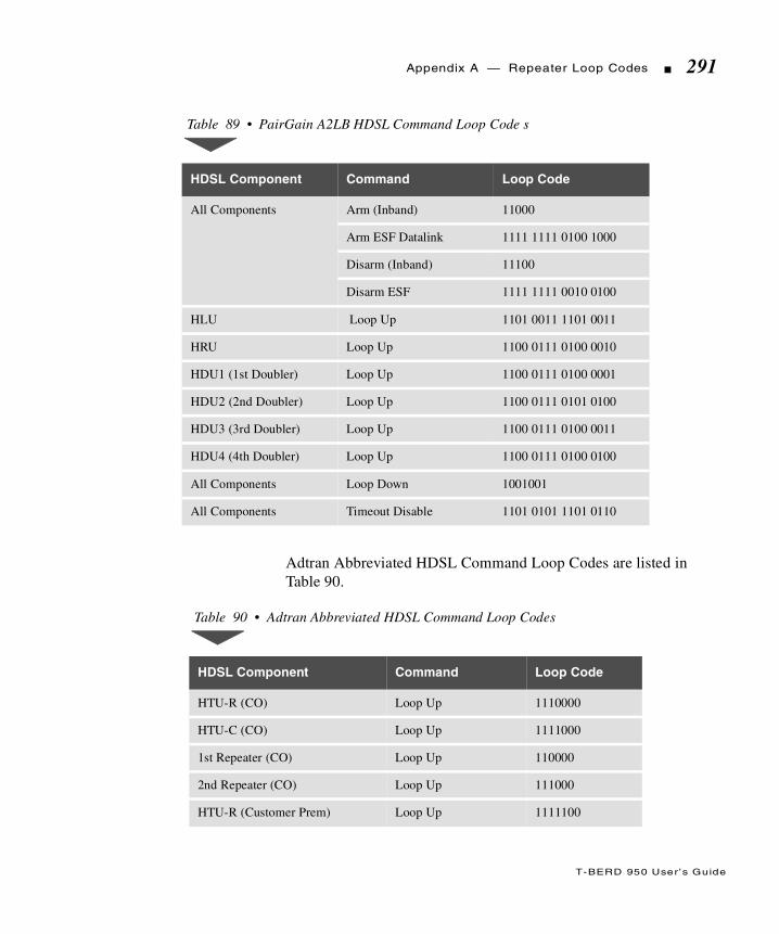
T-BERD 950 User ’s Guide
Appendix A — Repeater Loop Codes 291
Adtran Abbreviated HDSL Command Loop Codes are listed in Table 90.
Table 89 • PairGain A2LB HDSL Command Loop Code s
HDSL Component Command Loop Code
All Components Arm (Inband) 11000
Arm ESF Datalink 1111 1111 0100 1000
Disarm (Inband) 11100
Disarm ESF 1111 1111 0010 0100
HLU Loop Up 1101 0011 1101 0011
HRU Loop Up 1100 0111 0100 0010
HDU1 (1st Doubler) Loop Up 1100 0111 0100 0001
HDU2 (2nd Doubler) Loop Up 1100 0111 0101 0100
HDU3 (3rd Doubler) Loop Up 1100 0111 0100 0011
HDU4 (4th Doubler) Loop Up 1100 0111 0100 0100
All Components Loop Down 1001001
All Components Timeout Disable 1101 0101 1101 0110
Table 90 • Adtran Abbreviated HDSL Command Loop Codes
HDSL Component Command Loop Code
HTU-R (CO) Loop Up 1110000
HTU-C (CO) Loop Up 1111000
1st Repeater (CO) Loop Up 110000
2nd Repeater (CO) Loop Up 111000
HTU-R (Customer Prem) Loop Up 1111100
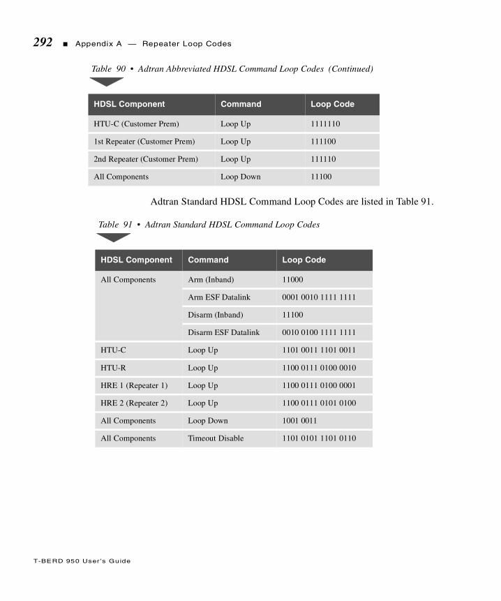
T-BERD 950 User ’s Guide
292 Appendix A — Repeater Loop Codes
Adtran Standard HDSL Command Loop Codes are listed in Table 91.
HTU-C (Customer Prem) Loop Up 1111110
1st Repeater (Customer Prem) Loop Up 111100
2nd Repeater (Customer Prem) Loop Up 111110
All Components Loop Down 11100
Table 91 • Adtran Standard HDSL Command Loop Codes
HDSL Component Command Loop Code
All Components Arm (Inband) 11000
Arm ESF Datalink 0001 0010 1111 1111
Disarm (Inband) 11100
Disarm ESF Datalink 0010 0100 1111 1111
HTU-C Loop Up 1101 0011 1101 0011
HTU-R Loop Up 1100 0111 0100 0010
HRE 1 (Repeater 1) Loop Up 1100 0111 0100 0001
HRE 2 (Repeater 2) Loop Up 1100 0111 0101 0100
All Components Loop Down 1001 0011
All Components Timeout Disable 1101 0101 1101 0110
Table 90 • Adtran Abbreviated HDSL Command Loop Codes (Continued)
HDSL Component Command Loop Code

T
T-BERD 950 User ’s Guide
his glossary contains definitions for acronyms, abbreviations and terms used throughout this guide.
Append ixB Glossary

T-BERD 950 User ’s Guide
294 Appendix B Glossary
Glossary
AIS Alarm Indication Signal (Blue Alarm)
AMI Alternate Mark Inversion
Associated Path Configured to be on the same T1 Path
AUX Auxiliary
B1 or B2 First or Second Bearer Channel
B8ZS Bipolar 8 Zero Substitution
BECN Backward Explicit Congestion Notification
BER Bit Error Rate
BERT Bit Error Rate Test(ing)
BPV Bipolar Violation
BRI Basic Rate Interface
Bridgetap Automated test that transmits 21 consecutive test patterns: ALL ONES, 1:1, 1:3,1:5, 1:6, 1:7, 2:8, 2:9, 2:10, 2:11, 2:12, 2:13, 2:14, 3 in 18, 3 in 19, 3 in 20,3 in 21, 3 in 22, 3 in 23, 3 in 24, and QRSS.
CLIP Calling Line Identification Presentation
C/R Command/Response Indication
CO Central Office
CPE Customer Premise Equipment
CSU Channel Service Unit
D&I Drop and Insert
DCE Data Communications Equipment
DDS LL Digital Data System Local Loop
DE Discard Eligibility
DLCI Data Link Connection Identifier
DL-LLB Data Link - Line Loopback
DL-Net Data Link - Network Loopback
DL-PLB Data Link - Payload Loopback

T-BERD 950 User ’s Guide
Appendix B Glossary 295
DN Directory Number (part of SPID)
DP Dial Pulse
DSP Digital Signal Processor
DSU Data Service Unit
DSX Digital Cross Connect
DTE Data Terminal Equipment
DTMF Dual Tone Multifrequency
EOC Embedded Operations Channel (U Interface)
EQUIPMENT switch Switch used to select T1 EQUIPMENT interface results to appear on the analyzerTwo-Line Display
ESF Extended Superframe
ETSI European Telecommunications Standards Institute
FAC Facility Access Code
FCS Frame Check Sequence
FECN Forward Explicit Congestion Notification
FT1 Fractional T1
FXO Foreign Exchange Channel Unit - Office End
FXS Foreign Exchange Channel Unit - Station End
HDLC High Level Data Link Control
HDSL High bit-rate Digital Subscriber Line
HELP key Key used to access help related to the active selection line. Information is willappear on the Large Graphical Display.
ISDN Integrated Services Digital Network
ITU International Telecommunication Union
KP Key Pulse
LAPD Link Access on the D-Channel
Large Graphical Display The 3.75” x 2.75” liquid crystal display used for the Home, Setup, Results, andSystem views.
LBO Line Build Out

T-BERD 950 User ’s Guide
296 Appendix B Glossary
LCD Liquid Crystal Display
LE Local Exchange or Network Cloud, implies protocol layers
LL Local Loop
LLB Line Loop Back
LMI Local Management Interface
LT Local Termination (U Interface) implies physical layer
MF Multifrequency
Multipat Automated test that transmits 5 consecutive test patterns: ALL ONES, 1:7, 2:8,3 in 24, and QRSS.
Multipat 2 Automated test that transmits 5 consecutive test patterns: 3 in 24, 1:7, ALLONES, QRSS, ALL ZERO.
NLPID Network Level Protocol Identifier
NT, NT1 Network Terminal (converts U to S/T interfaces)
OCU-DP Office Channel Unit - Data Port
PBX Private Branch Exchange
PCM Pulse Code Modulation
PRI Primary Rate Interface
PVC Permanent Virtual Circuit
QRSS Quasi-Random Signal Sequence
SAPI Service Access Port Identifier
SF Superframe
SLC Subscriber Loop Carrier
SNAP Subnetwork Access Protocol
SNOT Sequence Number Only Test
SPID Service Profile Identifiers
ST Start Signal
STP Start Signal Prime
ST2P Start Signal Two Prime
ST3P Start Signal Three Prime
T-BERD 950 User ’s Guide
Appendix B Glossary 297
T1 path Path of signal flow, a T1 receiver and its associated Transmitter.
TA Terminal Adapter
Two-Line Display Two-line liquid crystal display used for results and error/status messages
TERM Terminate
TIMS Transmission Impairment Measurement Set
UDF User Defined Frame
VF Voice Frequency

T-BERD 950 User ’s Guide
298 Appendix B Glossary

T
T-BERD 950 User ’s Guide
I n d ex
he index provides an alphabetized listing of terms and acronymsused throughout this guide.
300 Index
T-BERD 950 User’s Guide
— Numerics —
10BaseTping testing 260status and alarm LEDs 267, 268TNT view 262
10BaseT Optiondescription 260specifications 261
10BaseT Test Results 266interface category 269performance category 273summary category 268test type category 271
10BaseT Test Setupinterface view 264test type view 264
10BaseT Testingmanual 263TNT 262, 263
3 Tones Test 206
— A —
Acterna Contacts iii
Acterna Customer Services 275
Adtranabbreviated HDSL command loop codes 291standard HDSL command loop codes 292
Advanced Call ConfigurationsISDN BRI 242
Alarm Category Results 103
Alarm MessagesDDS option 128frame relay 152
Alarm/Status LEDsframe relay 147T1 93
Answering a CallISDN BRI 244ISDN PRI 169
AUTO Framing 64
AUTO Pattern Example 84
Available Options 112
— B —
Battery Operation 19charging batteries 19
Battery Replacement Procedure 20
— C —
CSU Emulation Testfractional T1 51T1 BERT 49T1 DDS 50
Customer Service Locations 276
Customer Servicesoverview 276
— D —
D-Channel DisplayISDN BRI option 245ISDN PRI option 170
DDS LLalarms 129status and alarm LEDs 126troubleshooting 118
DDS LL Control Codes 96
DDS LL InterfaceDDS troubleshooting 119frame relay turnup 138, 139

Index 301
T-BERD 950 User ’s Guide
DDS LL Optiondescription 114messages 116specifications 115
DDS LL Test Results 125interface category 127signal category 127, 128summary category 126test type category 126
DDS LL Test Setupinterface view 120test type view 123, 124TNT view 117
DDS LL Testingmanual 120monitor 119service turnup 117TNT 117TNT BERT turnup 118
DDS Loop Codes 68
Display Area 35
Drop & Insert Modepaths 8PCM TIMS option 204signaling option 180T1 interface 8
Dual Monitor Mode 8
— E —
E&M Signaling 184
EQUIPMENT Key/LEDs Settings 91
Equipment Receiver Results Controls and Indicators 91
Equipment Return Instructions 282service and repair information 282
Exterior Cleaning 22
Exterior Inspection 22
External Interface Requirements10BaseT option 261ISDN BRI option 223
— F —
Fractional T1BERT turnup 52CSU emulation test 51
Frame Relayalarms 153
Frame Relay Optiondescription 132messages 134specifications 134
Frame Relay Test Results 146performance category 151, 152summary category 148test type category 147
Frame Relay Test Setupinterface view 141test type view 141, 142
Frame Relay Testingmonitor 140TNT 134
Front Panel 10controls, indicators, and connectors 9, 11
Fuse Replacement 22
— G —
Getting Technical Assistance iii
Glossary 293
Ground StartFXO signaling 185FXS signaling 184signaling 184SLC office signaling 186SLC station signaling 185, 186

302 Index
T-BERD 950 User’s Guide
— H —
HDSL Equipment 74
Holding Tone Test 205
Home Viewlarge graphical display 30prompting area 31setting up 62title bar 30
— I —
Incoming Call ActivitiesISDN BRI option 244
Instrument Service 277customer services 277
Instrument Setup 6description 5
Interface Between NT and the Network 219
Interface Category Results10BaseT 268DDS LL 127frame relay 148ISDN BRI 248ISDN PRI 172T1 94View 34
Interface Result Viewtitle bar 34
Interface Setup View 32title bar 32
Interface View10BaseT 264frame relay 141ISDN BRI 234ISDN BRI BERT 231ISDN PRI 161PCM TIMS 208signaling 195
ISDN BRIadvanced call configurations 242call control 243call status and call failure report 252d-channel display 245loopbacks 223mode
LT BERT 220LT terminate 221NT1 BERT 221NT1 terminate 221NT1/TE 222NT1/TE terminate 222
option connectors 224placing calls 243
circuit 226packet 228
Q.931 cause codes 255receiving calls
circuit 226packet 228
S/T and U reference points 220SPID guess table 239status and alarm LEDs 247
ISDN BRI Optiondescription 218specifications 224U interface specifications 224
ISDN BRI Test Results 246interface category 248Q.931 cause codes reports 256summary category 247test type category 250test type view 235
Index 303
T-BERD 950 User ’s Guide
ISDN BRI Test SetupBERT interface view 231BERT test type view 232circuit calls 227ISDN interface view 234ISDN test type view 235line qualification test 226manual BERT test 230packet and advanced test type view 240packet calls 229TNT view 225
ISDN BRI Testingmanual 234TNT 225
ISDN BRI X.25 Test Resultscall type 253test type category 252, 253
ISDN PRId-channel display 170, 171incoming call activities 169placing calls 168Q.931 cause codes 176
ISDN PRI Call Control Features 167
ISDN PRI Optiondescription 156specifications 158
ISDN PRI Services 156
ISDN PRI Test Results 171call status 176d-channel backup 175Q.931 cause codes reports 176summary category 172test type category 173, 175
ISDN PRI Test Setupinterface view 161, 162manual test 161PBX emulation 159test type view 162TNT view 158
ISDN PRI Testingmonitor 160TNT test 158
— K —
Keyhelp 27
Keypad 14special functions 14
Keysfront panel
PCM TIMS option 212page 27scroll 27view 26
— L —
Large Graphical Display 30LEDs 26operation 25
LCD 90
Left Side Panel 15controls and connectors 14description 15
Line Loop Back (LLB) Mode 8paths 9
Locationscustomer service 276
Loop StartFXO signaling 187, 188FXS signaling 187SLC office signaling 188, 189SLC station signaling 188trunk type signaling 187
304 Index
T-BERD 950 User’s Guide
— M —
Main Display Controls 26
Manual SetupT1 54
Manual Test10BaseT 263DDS LL 120ISDN BRI 234ISDN BRI BERT test 230ISDN PRI 161PCM TIMS 208signaling 194T1 61, 62
Modes of Operation 7
Monitor Modeframe relay option 133ISDN PRI option 157PCM TIMS option 205signaling option 181
Monitor TestDDS LL 119frame relay 140ISDN PRI 160
— O —
Operating Modes10BaseT 260frame relay 132ISDN BRI 220ISDN PRI 157PCM TIMS 204signaling 180
Option Specifications10BaseT 261DDS LL 115frame relay 134ISDN BRI 224
ISDN PRI 158signaling 191
Options 111
— P —
PairGainA2LB HDSL command loop codes 291Generic HDSL command loop codes 289
PBX/Switch TurnupISDN PRI 192PCM TIMS 207signaling 193
PCM TIMSfront panel keys 212
PCM TIMS Optiondescription 204
PCM TIMS Test Results 212summary category 213test type category 214
PCM TIMS Test Setupinterface view 208test type view 209, 210
PCM TIMS Testingmanual 208TNT 206
PCMCIA Card Slot 16
Physical Specifications 42
Ping Testing10BaseT 260
Placing CallsISDN BRI 243ISDN BRI circuit 226ISDN BRI packet 228ISDN PRI 168
Preventive Maintenance 21

Index 305
T-BERD 950 User ’s Guide
Printer Operation 105configuration 106manual print screen 106non-volatile storage of prints 107printing 106timed print screen 107
Product Enhancement Group 278customer services 278
Prompting Areahome view 31results view 35setup view 33system view 39
— Q —
Quiet Test 206
— R —
Rear Panel 18view 19
Receiving CallsISDN BRI packet 228
Receiving Circuit CallsISDN BRI 226
Repeater Command Loop Codesteltrend 286westell 287XEL Line 289
Repeater Loop Codes 285
Repeaterscommand sets 73commands and addresses 73type 71
RESULTS I and IIdisplay controls and indicators 91
Results Viewprompting area 35T1 33
Right Side Panelcontrols and connectors 16, 17view 17
RJ-45 Pin Assignments 114
— S —
Selection Areahome view 31setup view 33system view 36
Self Loop Mode 9
Serviceinstrument 277
Service Locationscustomer 276
Services 277Acterna customer 275
Setup View 32prompting area 33
SignalingE&M 184manual dialing 182sequence types 181trunk types 183
Signaling Elements 189
Signaling Optioncall origination signaling 181call termination signaling 182description 180messages 192specifications 191
Signaling Sequences 182
Signaling Test Results 201summary category 201test type category 202
Signaling Test Setupinterface view 195test type view 196

306 Index
T-BERD 950 User’s Guide
Signaling Testingmanual 194TNT 192
Softkeys 28clear 29edit 28end 29HDSL commands 75home 29home view 32increase or decrease value 29repeater commands 75results view 35setup view 33system view 39
Softkeys Controls 28
SpecificationsT1 43
Standard E&M Signaling 183
Status and Alarm LEDs10BaseT 267, 268DDS LL 126ISDN BRI 247T1 93
Summary Category Results10BaseT 268DDS LL 126frame relay 148ISDN BRI 247ISDN PRI 172PCM TIMS 213signaling 201T1 92
Supervision Event Symbolsuser-defined signaling 190
System View 35, 36prompting area 39title bar 36
— T —
T1BERT patterns 81specifications 43status and alarm LEDs 93
T1 CSU emulation testBERT 49DDS 50
T1 InterfaceDDS frame relay turnup 137frame relay turnup 135PBX Emulation
ISDN PRI 158
T1 Loop Code Originating Messages 46
T1 Loop Codes 70
T1 Monitor Test 53signaling 193, 194
T1 Test Results 89, 92performance category 101signal category 98summary category 92
T1 Test SetupBERT turnup 50DDS turnup 51home view 62interface view 62, 63test type view 80
T1 Testingmanual 54, 61, 62
example 57task navigated testing (TNT) 47
Technical Training 279customer services 279
Teltrend Repeater Command Loop Codes 286
Index 307
T-BERD 950 User ’s Guide
Terminate Modedescription 7frame relay 132ISDN PRI 157PCM TIMS 204signaling 180
Test Configurationsexamples 54
Test ResultsDDS LL 125frame relay 146ISDN BRI 246ISDN PRI 171PCM TIMS 212signaling 201
Test Results Display 90
Test Routines3 tones test 206holding tone test 205quiet test 206variable tone test 205
Test Systems Field Engineering and Installation 278customer services 278
Test Type Category Results10BaseT 271frame relay 148ISDN BRI 248ISDN BRI X.25 252ISDN PRI 172PCM TIMS 213signaling 201T1 97
Test Type View10BaseT 264frame relay 141ISDN BRI 235ISDN BRI BERT 232ISDN PRI 162PCM TIMS 209signaling 196
Testing with the T-BERD 950 48
Time Category Results 100
Title Barhome view 30interface result view 34interface setup view 32system view 36
TNT Example 55
TNT Results View 57
TNT Setup View 56
TNT Task Mode, Setup, and Results 48
TNT Test10BaseT 262, 263DDS LL 117frame relay 134ISDN BRI 225ISDN PRI 158PCM TIMS 206signaling 192
Traffic Generation Testing 261
Trainingtechnical 279
TTC Test Frame Format 133
Two-Line Display Area 90
Typographical Conventions 2
— U —
U Interface 219
User Interface Configuration Requirements 108
User-Defined Signalingdigit type symbols 190supervision event symbols 190trunk type 189

308 Index
T-BERD 950 User’s Guide
— V —
Variable Tone Test 205
Voice Testing 79interface setup view 79
— W —
Warranty Information 280customer services 280
Westell Repeater Command Loop Codes 287
— X —
XEL Line Repeater Command Loop Codes 289
Top Related