


Languages
Pages
Legal

REPORT
Report prepared for:
Mighty River Power Ltd
Report prepared by:
Tonkin & Taylor Ltd
July 2011
T&T Ref:85143.001
Mighty River Power LtdPuketoi Windfarm Transmission Line ‐ Geotechnical & Civil

ii
Puketoi Windfarm Transmission Line - Geotechnical & Civil Job no. 85143.001 Mighty River Power Ltd July 2011
Table of contents
1 Introduction 1 1.1 Relationship of Engineering and Construction Management Reports 1 1.2 Transmission Line Description 3 1.3 Methodology 3 1.4 Transmission Structures 4
2 Geotechnical Assessment 4 2.1 Geology 4 2.2 Seismic Hazard 5
2.2.1 Ground Rupture 6 2.2.2 Ground Shaking 6 2.2.3 Liquefaction 6
2.3 Slope Stability 6
3 Foundation Solutions 8 3.1.1 Preliminary Design Parameters 9 3.1.2 Foundation Loads 10
3.2 Foundation Construction Considerations 10 3.2.1 Foundation Construction Plant 10 3.2.2 Tension Anchors 13
4 Construction Access to Transmission Structures 14 4.1 Design Philosophy 14
4.1.1 Use of existing tracks 17 4.1.2 Earthworks profiles 17 4.1.3 Pavement Design 17 4.1.4 Gradients 17
4.2 Fill Disposal Philosophy 18 4.3 Transport of Material to Site and Vehicle Movements 19
5 Construction and Environmental Management 19
6 Conclusions 19
7 Applicability 21
Appendix A: Transmission Line Access tracks – Lengths and Earthworks Volumes
Appendix B: Transmission Line – Construction Vehicle Traffic Volumes
1
Puketoi Windfarm Transmission Line - Geotechnical & Civil T&T Ref. 85143.001 Mighty River Power Ltd July 2011
1 Introduction
Tonkin & Taylor (T&T) have completed a geotechnical and civil assessment and access design for the proposed 220kV transmission line. This line is proposed to service the proposed Mighty River Power Ltd (MRP) Puketoi Windfarm. The 220 KV transmission line will extend from the proposed Windfarm on the Puketoi Range to the eastern side of the Tararua Range.
This assessment has focused on the following aspects:
Assessment of the likely geological conditions and geotechnical constraints along the proposed alignment
Foundation solutions for the transmission towers
Assess and select feasible access routes to the tower sites and quantify the associated roading and earthworks.
Assess likely vehicle movements (for construction) to inform the traffic assessment
1.1 Relationship of Engineering and Construction Management Reports
This assessment has been undertaken in conjunction with the civil and geotechnical assessments for the main windfarm project as well as the development of the construction and environmental management plan (CEMP). This report should be read in conjunction with those reports as they provide greater detail particularly in the areas of the regional geological setting and how the construction will be managed to minimise adverse effects. The relationship between each of these reports is summarised in Figure 1‐1 below.

2
Puketoi Windfarm Transmission Line - Geotechnical & Civil Job no. 85143.001 Mighty River Power Ltd July 2011
Geotechnical Investigation and Design Report
• Engineering / Structural Geology• Karst topography and geohydrology• Geotechnical conditions• Slope stability & Seismic considerations• Geotechnical properties • Earthworks development principals• Turbine Foundation design• Aggregate resources and road pavement
solutions
Civil Design Report• Description of proposed development• Road and earthworks design • Construction methodology• Water demand / Supply• Contractors amenities / laydown areas• Concrete batching• Bridge / stream crossing• Turbine laydown areas
Transmission Line Civil & Geotechnical Report
• Geological conditions and geotechnical constraints
• Tower Foundation Solutions• Roading and earthworks requirements
for access routes• Civil works construction methodology
Supplementary Environmental Management Plans (SEMPs)
SEMPs are location or activity specific and will be prepared with the relevant contractor to achieve the objectives outlined in the CEMP. Nine potential SEMPs are proposed for this project. SEMPs will include:• Actions to minimise extent and effects of earthworks• Identification of sites with special ecological and
archaeological values and measures to avoid or minimise impacts on these values
• Work programme• Schedule and plan of specific sediment control measures• Revegetation schedule• Monitoring schedule
Draft – Supplementary Environmental Management Plan #3
For track MC40 & Access to WT31 – 36. This plan has been developed as an example to
demonstrate how the objectives of the CEMP are likely to be achieved during construction and commissioning of the project. It contains procedures, schedules and drawings of the
construction and environmental management for this section of the project.
Draft Construction and Environmental Management Plan (CEMP)The Draft CEMP sets out the construction and management objectives for the construction and commissioning of the proposed windfarm & transmission line. This will remain a draft document until the conditions of consent are finalised and integrated into this document. Management procedures (described by this document) to avoid, remedy or mitigate effects may include:
• Hours of works• Earthworks management• Erosion and sediment Control• Revegetationand Stabilisation
• Dust control• Visual mitigation• Culverts & fords• and others
Figure 1‐1: Relationship of Engineering and Construction Management Reports
3
Puketoi Windfarm Transmission Line - Geotechnical & Civil T&T Ref. 85143.001 Mighty River Power Ltd July 2011
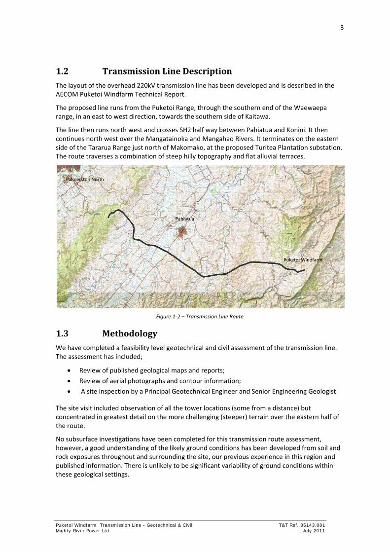
1.2 Transmission Line Description
The layout of the overhead 220kV transmission line has been developed and is described in the AECOM Puketoi Windfarm Technical Report.
The proposed line runs from the Puketoi Range, through the southern end of the Waewaepa range, in an east to west direction, towards the southern side of Kaitawa.
The line then runs north west and crosses SH2 half way between Pahiatua and Konini. It then continues north west over the Mangatainoka and Mangahao Rivers. It terminates on the eastern side of the Tararua Range just north of Makomako, at the proposed Turitea Plantation substation. The route traverses a combination of steep hilly topography and flat alluvial terraces.
Figure 1‐2 – Transmission Line Route
1.3 Methodology
We have completed a feasibility level geotechnical and civil assessment of the transmission line. The assessment has included;
Review of published geological maps and reports;
Review of aerial photographs and contour information;
A site inspection by a Principal Geotechnical Engineer and Senior Engineering Geologist
The site visit included observation of all the tower locations (some from a distance) but concentrated in greatest detail on the more challenging (steeper) terrain over the eastern half of the route.
No subsurface investigations have been completed for this transmission route assessment, however, a good understanding of the likely ground conditions has been developed from soil and rock exposures throughout and surrounding the site, our previous experience in this region and published information. There is unlikely to be significant variability of ground conditions within these geological settings.
Puketoi Windfarm
Pahiatua
Palmerston North

4
Puketoi Windfarm Transmission Line - Geotechnical & Civil Job no. 85143.001 Mighty River Power Ltd July 2011
1.4 Transmission Structures
Three different types of transmission structures are proposed for the 220kV Transmission line. These are:
Mono Poles
Double Poles
Lattice Towers
For examples and locations of these structures see the AECOM Puketoi Windfarm Technical Report.
2 Geotechnical Assessment
2.1 Geology
The geological setting of the proposed transmission line is described in the Institute of Geological and Nuclear Sciences (GNS) report on the Geology of the Wairarapa Area1. This geology was generally confirmed in our site visit.
The range of geological materials likely to be encountered across the proposed transmission alignment can be separated into:
Surfical soils (i.e. loess or colluvium);
Alluvial (river) terraces comprising sands, silts and gravels;
Weak Limestones, mudstones, siltstones and sandstones forming hills from the Puketoi
site through to Pahiatua;
Stronger greywacke sandstones and siltstones at the western end of the route;
Pliocene aged Onoke group sediments make up the majority of the landscape east of Pahiatua. These sediments comprise limestone, sandstone, siltstone and mudstones. These materials are described in detail in the Windfarm geotechnical report. The limestone mainly outcrops at the eastern end of the proposed routes around towers 1 to 8 and 12. Limestone is also likely to be encountered around towers 67 to 69 inclusive, and 79 to 83 inclusive. The remaining towers on the hill slopes east of the tower 99 are underlain by weak mudstones, siltstones and sandstones.
Pleistocene aged alluvial terraces (Q2a) infill some of the low lying basins and valleys along the proposed transmission route. These materials are described by Lee & Begg (2002) as moderately to poorly sorted gravel with minor sand or silt.
The proposed transmission route dissects numerous rivers and tributaries. The main watercourses intercepted by the proposed scheme are the Makuri Stream and the Mangahao and Mangatainoka Rivers. These watercourses have surrounding flood plains of varying size where alluvial sediments periodically deposit. These materials will comprise variable mixtures of gravels, sands and silts.
1 Lee, J.M.; Begg, J.G. (compilers) 2002: Geology of the Wairarapa area. Institute of Geological & Nuclear Sciences 1:250 000 geological map 11. 1 sheet + 66p. Lower Hutt, New Zealand. Institute of Geological and Nuclear Science Limited.

5
Puketoi Windfarm Transmission Line - Geotechnical & Civil T&T Ref. 85143.001 Mighty River Power Ltd July 2011
Table 2‐1: Topographical and Geological founding unit at each transmission structure site.
Tower Number Tower Type Topography Geological Unit
1 & 2 Lattice Hills Limestone with sand mantle
3 to 8 Limestone/Siltstone
9 Alluvium
10 &11 Siltstone/Mudstone
12 Limestone/Siltstone
13 to 47 Siltstone/Mudstone
48 to 49 Pole Hills Siltstone/Mudstone
50 to 51 Terrace Alluvium
52 to 64 Hills Siltstone/Mudstone
65 to 69 Hills Limestone/ Siltstone
70 to 78 Terrace Alluvium
79 to 83 Hills Limestone/ Siltstone
84 to 91 Terrace Alluvium
92 to 95 Hills Siltstone/Mudstone/limestone
96 to 98 Terrace Alluvium
99 Lattice Terrace Alluvium
100 to 111 Hills Greywacke Sandstone and Siltstone
2.2 Seismic Hazard
The region is situated in a highly deformed and seismically active zone. The steep topographic environment is a result of millions of years of reverse/thrust faulting and folding. Two active fault lines (Lee & Begg, 2002) intersect by the proposed transmission alignment. These are the Makuri – Waewaepa Fault and the Wellington – Mohaka Fault.
The Makuri – Waewaepa Fault runs north east to south west to the west of the Puketoi Range. This fault is a northern extension of the Wairarapa Fault and is located immediately west of Coonoor Road to the west of the windfarm site. The reoccurrence interval of the Makuri – Waewaepa Fault is estimated to be between 2000 and 3500 years.
The main Wairarapa Fault has a rupture reoccurrence interval of nearly 2000 years and is capable of producing an earthquake of moment magnitude (Mw) of 8.0‐8.3. The moment magnitude scale (Mw) is used by seismologists to measure the size of earthquakes in terms of the energy released.
The Wellington – Mohaka Fault is a major fault line that runs along the eastern toe of the Tararua Ranges, trending northeast to southwest. The proposed alignment dissects this fault line north of the Makomako settlement where the fault has been accurately marked. The fault has been
6
Puketoi Windfarm Transmission Line - Geotechnical & Civil Job no. 85143.001 Mighty River Power Ltd July 2011
described by Lee & Begg (2002) to have an estimated single displacement of 3.5‐5m, with the estimated characteristic earthquake magnitude of 7.0‐7.3 Mw with a reoccurrence interval of 500 to 770 years.
2.2.1 Ground Rupture
Proposed transmission structures are located clear of the two active faults. The Wellington Mohaka fault extends between towers 99 and 100. The Makuri ‐ Waewaepa fault passes between towers 13 and 14.
Lateral displacement on these faults of up to 5m in the maximum likely earthquakes would be tolerated by the transmission line without significant damage.
2.2.2 Ground Shaking
The earthquake ground shaking hazard for this region is generally comparable to the hazard of the remainder of the lower North Island. The towers, foundations and critical infrastructure should be designed to tolerate ground shaking and seismic loading as required by New Zealand Standard for determination of earthquake actions; NZS 1170.5:2004.
The proposed transmission tower foundation solutions (shown on drawings MRP‐PKT‐3240 to 3244) are likely to meet these requirements. Specific seismic design of each element will be required prior to construction. This design should be based on an assessment of soil conditions at each specific site.
2.2.3 Liquefaction
Liquefaction can occur under earthquake shaking in loose, saturated, sandy soils.
Liquefaction risk is very low for tower foundation sites on elevated or hill slopes. There is a risk of potential liquefaction on the low lying alluvial terraces and river flood plains. Site specific geotechnical investigations will be undertaken during detailed design. Structures in locations with a moderate or high liquefaction risk will require foundations designed to tolerate liquefaction.
Piled foundations will generally tolerate liquefaction well. However specific investigations and design should be completed during detailed design prior to construction to:
Confirm foundation piles extend to sufficient depth to found onto non liquefiable stratum.
Tolerate lateral spreading. Lateral spreading can occur where liquefied soils can flow sideways towards a free edge (e.g. stream, river or drainage ditch). Foundation systems can be designed to have sufficient lateral restraint to resist lateral spreading. Inclined ground anchors, ground improvement or additional piles may be required in such instances.
The only towers that may have a moderate to high risk of lateral spreading are towers no. 9, 50, and 51, 70‐78, 84‐91 and 96‐99.
2.3 Slope Stability
Slope instability risk is very low on the low gradient terraces and flood plains. The risk of slope instability is also very low on the limestone slopes underlying towers 1 to 8 and 12. This is because of the relatively high strength of the limestone rock. Subject to confirmation by site specific investigations, limestone is also likely to be encountered under the footprints of towers 67, 68, 69 and 79 to 83 inclusive.

7
Puketoi Windfarm Transmission Line - Geotechnical & Civil T&T Ref. 85143.001 Mighty River Power Ltd July 2011
Slope instability of the remaining hill slopes (mudstones and siltstones) is common. The silt and mudstones in particular are prone to shallow surface landslips on steep slopes during heavy rainfall. This mechanism is caused by the poor drainage characteristics of the rock and the slow surface weakening of the material. This surface weakening is common in silt and mudstones on steep slopes and occurs as a combination of stress release and surface shrink / swell due to wetting and drying cycles. These landslips are typically of less than 1m depth.
There are isolated (rare) examples of larger landslips within these materials. Several tower sites have been relocated to avoid and provide setback from potential landslip features. Typically the towers are located close to ridge lines where there are better drainage conditions and locally flatter slopes. These attributes significantly reduce the risk of slope instability.
Any towers that cannot be sited clear of potential shallow landslips can be designed to resist lateral ground movement. The proposed piled foundation design for lattice towers would typically be able to resist landslip movement of up to 2m depth (and greater depth with specific provisions such as lateral ground anchors).
Following our inspection we are satisfied the current layout is feasible and the effects of ground instability can be mitigated through minor positional adjustments and specific foundation design.
Table 2‐2 outlines the specific geotechnical constraints associated with specific geological materials and how these will be managed through detailed design and construction.
Table 2‐2: Geotechnical considerations for towers in different geological materials
Material Type Geotechnical Consideration / Constraint
Recommendations to Avoid or Mitigate
Onoke Group Limestone (Totaranui, Te Onepu, Rongomai)
Pep, Pet, Per
Karst topography and associated features (surface outcrops, sinkholes and cavities).
Avoid all surface karst features. The lateral extent of these features is typically limited and can be avoided in site selection.
Onoke Group Mangaoranga Formation
(Mudstones and Siltstones)
Undifferentiated Onoke Group mudstones and sandstones
Ms
Pea
Soil creep and shallow instability on steep slopes (greater than 25o). Shallow translational sliding common on steeper slopes, after heavy rainfall.
Position towers away from observed instability.
Where practical position towers on ridges, spurs or slopes shallower than 20o.
Where stability risk remains use piled foundations to resist shallow ground movement.
Alluvial Flood Plain Q1a
&
Q2a
Saturation of footings during flood events (reduction in foundation capacity).
Potential for low strength, compressible layers interbedded within gravels.
Liquefaction of saturated silts and sands.
Design foundations to tolerate saturated conditions.
Investigations and foundations to accommodate silt layers where located .
Foundations to suitably dense (non liquefiable) layers confirmed by investigations.
Alluvial Terrace Q3a Minimal risk Unlikely to require any specific measures.
Weathered Alluvial Terrace Gravel
eQa Minimal risk Unlikely to require any specific measures.
8
Puketoi Windfarm Transmission Line - Geotechnical & Civil Job no. 85143.001 Mighty River Power Ltd July 2011
Material Type Geotechnical Consideration / Constraint
Recommendations to Avoid or Mitigate
Greywacke Te Wedge or planar instability on edge of incised or oversteepened slopes;
Shallow colluvium instability.
Position towers away from steep slope edges or design to resist lateral creep movement.
3 Foundation Solutions
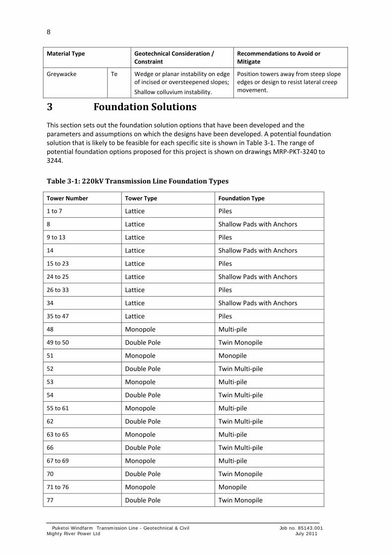
This section sets out the foundation solution options that have been developed and the parameters and assumptions on which the designs have been developed. A potential foundation solution that is likely to be feasible for each specific site is shown in Table 3‐1. The range of potential foundation options proposed for this project is shown on drawings MRP‐PKT‐3240 to 3244.
Table 3‐1: 220kV Transmission Line Foundation Types
Tower Number Tower Type Foundation Type
1 to 7 Lattice Piles
8 Lattice Shallow Pads with Anchors
9 to 13 Lattice Piles
14 Lattice Shallow Pads with Anchors
15 to 23 Lattice Piles
24 to 25 Lattice Shallow Pads with Anchors
26 to 33 Lattice Piles
34 Lattice Shallow Pads with Anchors
35 to 47 Lattice Piles
48 Monopole Multi‐pile
49 to 50 Double Pole Twin Monopile
51 Monopole Monopile
52 Double Pole Twin Multi‐pile
53 Monopole Multi‐pile
54 Double Pole Twin Multi‐pile
55 to 61 Monopole Multi‐pile
62 Double Pole Twin Multi‐pile
63 to 65 Monopole Multi‐pile
66 Double Pole Twin Multi‐pile
67 to 69 Monopole Multi‐pile
70 Double Pole Twin Monopile
71 to 76 Monopole Monopile
77 Double Pole Twin Monopile

9
Puketoi Windfarm Transmission Line - Geotechnical & Civil T&T Ref. 85143.001 Mighty River Power Ltd July 2011
78 to 79 Monopole Monopile
80 Double Pole Twin Multi‐pile
81 to 83 Monopole Multi‐pile
84 Double Pole Twin Monopile
85 to 86 Monopole Monopile
87 to 88 Double Pole Twin Multi‐pile
89 to 91 Monopole Monopile
92 to 94 Double Pole Twin Multi‐pile
95 Monopole Multi‐pile
96 to 98 Monopole Monopile
99 to 111 Lattice Piles
The main engineering considerations for foundation selection at each tower site are:
Likely geological characteristics (including strength)
Structure type and applied loads
Slope stability
Access constraints
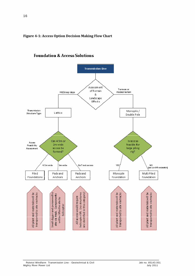
Access constraints dictate the type of machinery (plant) that can access a particular site. The size and type of plant that can access a location strongly influences the type of foundation that will be feasible at that location. The decision process for selecting the access design and the proposed foundation solution is summarised in Section 4.1 and Figure 4‐1.
3.1.1 Preliminary Design Parameters
Towers will found in a range of soil and rock conditions. We have assessed two different soil envelopes. These two envelopes are likely to conservatively represent the lower bound of conditions likely to be encountered.
We have developed foundation solutions for:
Cohesionless or granular material representative of alluvial deposits.
Cohesive material representative of the weak sedimentary rock such as mudstone and siltstone.
Table 3‐1: Geotechnical foundation design parameters for transmission towers
Representative Material Friction Angle φ Cohesion c (kPa) Undrained Shear Strength Su (kPa)
Granular Material 35° 0 ‐
Cohesive Material ‐ ‐ 200kPa
10
Puketoi Windfarm Transmission Line - Geotechnical & Civil Job no. 85143.001 Mighty River Power Ltd July 2011
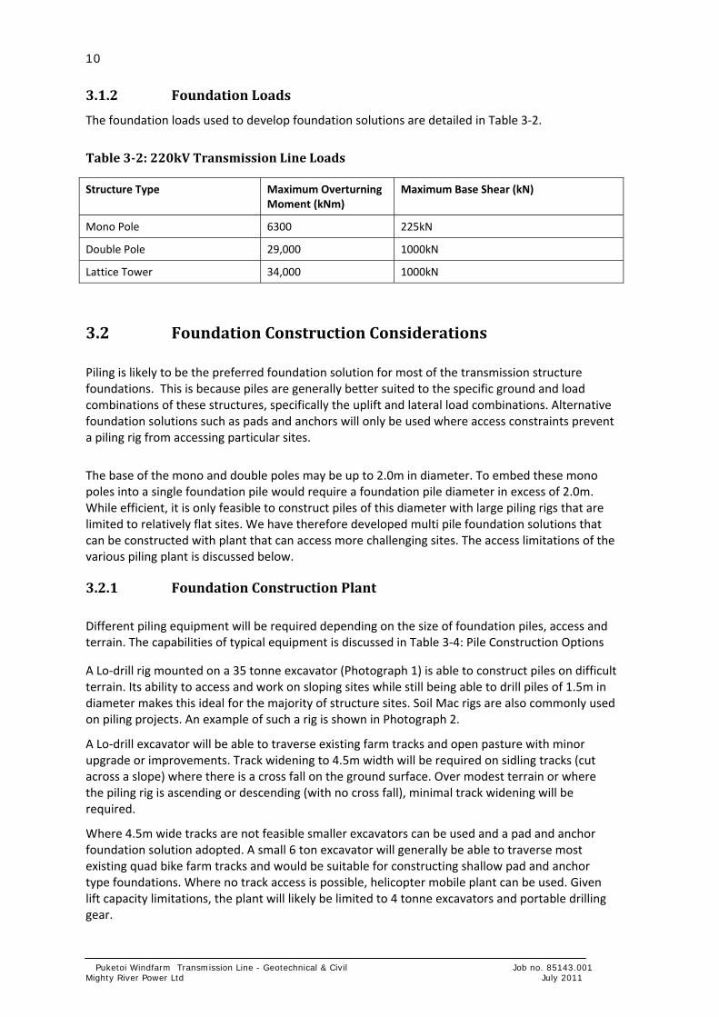
3.1.2 Foundation Loads
The foundation loads used to develop foundation solutions are detailed in Table 3‐2.
Table 3‐2: 220kV Transmission Line Loads
Structure Type Maximum Overturning Moment (kNm)
Maximum Base Shear (kN)
Mono Pole 6300 225kN
Double Pole 29,000 1000kN
Lattice Tower 34,000 1000kN
3.2 Foundation Construction Considerations
Piling is likely to be the preferred foundation solution for most of the transmission structure foundations. This is because piles are generally better suited to the specific ground and load combinations of these structures, specifically the uplift and lateral load combinations. Alternative foundation solutions such as pads and anchors will only be used where access constraints prevent a piling rig from accessing particular sites.
The base of the mono and double poles may be up to 2.0m in diameter. To embed these mono poles into a single foundation pile would require a foundation pile diameter in excess of 2.0m. While efficient, it is only feasible to construct piles of this diameter with large piling rigs that are limited to relatively flat sites. We have therefore developed multi pile foundation solutions that can be constructed with plant that can access more challenging sites. The access limitations of the various piling plant is discussed below.
3.2.1 Foundation Construction Plant
Different piling equipment will be required depending on the size of foundation piles, access and terrain. The capabilities of typical equipment is discussed in Table 3‐4: Pile Construction Options
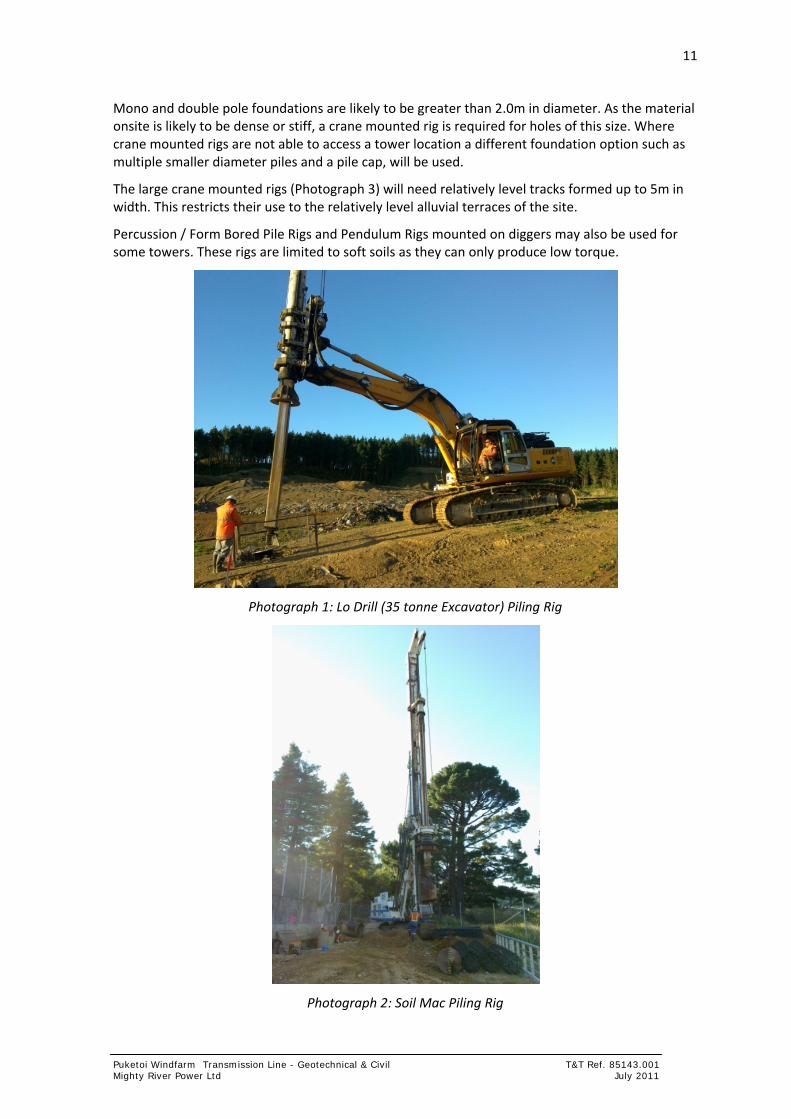
A Lo‐drill rig mounted on a 35 tonne excavator (Photograph 1) is able to construct piles on difficult terrain. Its ability to access and work on sloping sites while still being able to drill piles of 1.5m in diameter makes this ideal for the majority of structure sites. Soil Mac rigs are also commonly used on piling projects. An example of such a rig is shown in Photograph 2.
A Lo‐drill excavator will be able to traverse existing farm tracks and open pasture with minor upgrade or improvements. Track widening to 4.5m width will be required on sidling tracks (cut across a slope) where there is a cross fall on the ground surface. Over modest terrain or where the piling rig is ascending or descending (with no cross fall), minimal track widening will be required.
Where 4.5m wide tracks are not feasible smaller excavators can be used and a pad and anchor foundation solution adopted. A small 6 ton excavator will generally be able to traverse most existing quad bike farm tracks and would be suitable for constructing shallow pad and anchor type foundations. Where no track access is possible, helicopter mobile plant can be used. Given lift capacity limitations, the plant will likely be limited to 4 tonne excavators and portable drilling gear.
11
Puketoi Windfarm Transmission Line - Geotechnical & Civil T&T Ref. 85143.001 Mighty River Power Ltd July 2011
Mono and double pole foundations are likely to be greater than 2.0m in diameter. As the material onsite is likely to be dense or stiff, a crane mounted rig is required for holes of this size. Where crane mounted rigs are not able to access a tower location a different foundation option such as multiple smaller diameter piles and a pile cap, will be used.
The large crane mounted rigs (Photograph 3) will need relatively level tracks formed up to 5m in width. This restricts their use to the relatively level alluvial terraces of the site.
Percussion / Form Bored Pile Rigs and Pendulum Rigs mounted on diggers may also be used for some towers. These rigs are limited to soft soils as they can only produce low torque.
Photograph 1: Lo Drill (35 tonne Excavator) Piling Rig
Photograph 2: Soil Mac Piling Rig

12
Puketoi Windfarm Transmission Line - Geotechnical & Civil Job no. 85143.001 Mighty River Power Ltd July 2011
Photograph 3 Crane Mounted Piling Rig
Photograph 4 Tractor mounted drill rig for ground anchors

13
Puketoi Windfarm Transmission Line - Geotechnical & Civil T&T Ref. 85143.001 Mighty River Power Ltd July 2011
Table 3‐4: Pile Construction Options
Rig Access Required
Width Required
Setup Terrain
Capabilities
Hole size Depth Description
Crane Mounted
Good
5m
Flat Up to 2.8m Depends on ground
>10m
Crane Mounted Drill Rig (80 tonne or greater). Limited by access and working platform, which needs to be flat.
Soil Mac Good
4m
Slight Slopes Up to 1.5m 60m Typical drill rig used on most piling jobs. Tolerant to slightly unlevel terrain.
Lo‐Drill Excavator
Poor
4.5m
Difficult Terrain
Up to 2m Depending on Torque (Likely 1.5m)
30m Hole size is dictated by torque the pin can take on the extendable arm. 35 tonne excavator mounted rig can do piles up to 2m in diameter depending on ground conditions.
Percussion/Form Bored Pile
Heli
2m
Difficult Terrain
Up to 0.6m Deep Percussion/Form bored pile is a down hole drop hammer with segmental casing. Can drill holes up to 600mm dia in all material including rock. Casing is able to be jacked out during pile installation. Can be time consuming and is not as efficient in soft rocks.
Pendulum Rig Mounted on Digger
Digger
4.5m
Difficult Terrain
<0.6m Low Torque
Limited
Estimate <10m
Digger mounted. Limited to soft soils. Only able to produce low torque.
Pendulum Rig Mounted on Digger
Heli
2m
Difficult Terrain
<0.4m Very Low Torque
Limited
Estimate <5
Digger mounted Limited to 4 tonne. Limited to very soft soils. Only able to produce very low torque.
3.2.2 Tension Anchors
Tension anchors improve the efficiency of the shallow pad foundations by preventing uplift on one side of the foundation. Anchors can only resist tension loads so they are used as tie downs to resist uplift. Anchors would be used in conjunction with shallow concrete pads. This type of solution is most likely to be adopted where helicopter access is the preferred option. Anchors can be constructed using portable equipment transported to site by helicopter. Ground anchors can be constructed in all of the ground conditions likely to be encountered. Tractor mounted drill rigs for anchors can also be used (Photograph 4).

14
Puketoi Windfarm Transmission Line - Geotechnical & Civil Job no. 85143.001 Mighty River Power Ltd July 2011
Shallow pads and anchors do not tolerate lateral ground movement as well as piles. They are therefore not suited to sites where there is a risk of lateral ground movement. This can be mitigated by excavating a stable platform for each pad or installing additional stabilising works such as lateral ground anchors or retaining walls.
Other disadvantages of anchors include expense, time to construct, as well as higher maintenance requirements such as pre stressing, load testing and corrosion prevention and monitoring.
Where ground anchors are used, a long term inspection and testing regime will be developed.
4 Construction Access to Transmission Structures
To facilitate the construction of the transmission structure, plant, labour and materials will need to be transported to site. The main components that will need to be transported to each site include:
Plant for excavation of the foundations.
Concrete and reinforcing steel for the foundations.
The structural components for the lattice towers or poles. Each of these will be transported to site in components.
Lifting equipment.
Conductors and other electrical components .
We have assessed and selected feasible routes to access each transmission tower location. Suggested feasible access route options are shown on drawings MRP‐PKT‐ 3221 to 3230.
The access track design shows the likely worst case extent of the proposed roading. As a contractor is appointed and detailed designs are finalised there could potentially be a reduction in track development (less 4.5m tracks and more 2m tracks) and greater use of helicopters. The final arrangements may differ slightly following contractors involvement and synchronisation with farm operational requirements. However the overall principals, scale and effects will be similar.
The key attributes of the proposed access tracks are summarised in Table 4‐1.
Table 4‐1: Key attributes of proposed accessed tracks
Attribute Approximate Total
Total Length of access tracks
Length of existing tracks to be upgraded
Length of new access tracks to be constructed
64.3 km
47.7 km
16.6 km
Volume of total earth works (predominantly cut to on site disposal) 116,000 m³
Volume of imported metal (running course) 16,100 m³
A more detailed breakdown of proposed road lengths and earthworks estimates is provided in Appendix A.
4.1 Design Philosophy
We have assessed the feasibility of providing track access to each transmission structure site. A simplified flow chart of the decision process is illustrated in Figure 4‐1 and summarised below. In assessing the feasibility of each access track, we have considered:

15
Puketoi Windfarm Transmission Line - Geotechnical & Civil T&T Ref. 85143.001 Mighty River Power Ltd July 2011
Is it practical to construct a 4.5m wide access track to the site without excessive earthworks or environmental impact, i.e. vegetation clearance?
o Note for the monopole and double pole sites it will not be feasible to transport the pole sections to the sites by helicopter so truck access to the sites is essential.
If it is not practical to construct a 4.5m track, can a 2m wide track be formed to allow a small excavator and personnel to access the site. Small all terrain vehicles (ATVs) will also be able to use a 2m wide track. This reduces helicopter movements.
A 4.5m wide track will allow a Lo drill excavator to access sites and construct a piled foundation. As discussed in section 3, piled foundations are typically favoured.
Based on our assessment of the site, feasible track access can be constructed to provide (either 2m or 4.5m wide) drive on access to all transmission structure sites. This will allow a 6 or 35 ton excavator to access each site respectively.
16
Puketoi Windfarm Transmission Line - Geotechnical & Civil Job no. 85143.001 Mighty River Power Ltd July 2011
Figure 4‐1: Access Option Decision Making Flow Chart
17
Puketoi Windfarm Transmission Line - Geotechnical & Civil T&T Ref. 85143.001 Mighty River Power Ltd July 2011
4.1.1 Use of existing tracks
The proposed access track design is based heavily on the use of existing access tracks. Table 4‐1 shows the relative lengths of new tracks compared to upgrade of existing tracks. 75% of the total track system is likely to be based on existing access tracks.
4.1.2 Earthworks profiles
The recommended soil and rock design parameters provided in the windfarm geotechnical report are appropriate for use in the earthworks design for the transmission line project. The majority of the earthworks for the transmission access tracks will be within siltstones and mudstones. Recommended cut and fill batter slopes for these materials are:
Max Cut batter Slope = 63° (1V:0.5H)
Max Fill batter slope = 26° (1V:2H)
4.1.3 Pavement Design
Most of the tracks on the hill slopes will be underlain by siltstone and mudstone derived materials. These materials are typically poorly drained and become slippery when wet. The tracks will have a metalled running surface of 2.5 to 3m in width for the 4.5m wide tracks. Approx 1.5m of the 2m wide tracks will be metalled.
The metalled running surface will improve traction as well as minimise dust generation and sediment runoff from erosion.
The full width of access track does not require metal as the full width is required only for the tracked pile drilling equipment and other excavators. Additional metal will be placed where passing bays are desired to allow trucks to pass each other.
4.1.4 Gradients
The gradients of the existing farm tracks are unlikely to alter significantly following upgrading of tracks. The finished gradients of the tracks and the weather conditions will dictate the type of vehicles that can gain access to the sites rather than setting a target gradient for all access tracks. Excavators and the Lo drill rig are likely to be able to climb slopes as steep as 1V to 2H or 26 degrees which is significantly steeper than any of the proposed tracks. Standard concrete trucks are likely to be able to climb most of the proposed 4.5m wide tracks during dry conditions. Where conditions prevent access by standard concrete trucks specialised ATV vehicles will be used. An example of an all terrain concrete mixer is shown in Photograph 5.
18
Puketoi Windfarm Transmission Line - Geotechnical & Civil Job no. 85143.001 Mighty River Power Ltd July 2011
Photograph 5: – All terrain concrete mixer, rated to climb 1 in 3 gradients fully loaded.
4.2 Fill Disposal Philosophy
The proposed access tracks on the hill slopes will predominantly be formed by cutting the full width of track into the slope. This will generate an excess of cut to fill. On steeper slopes where a new 4.5m wide track is to be formed, this may generate fill to disposal of up to 5000 m³/km. The total amount of fill to disposal for access tracks is likely to be less than 93,000m³ or 80% of the total earthworks volume. The remaining 20% is likely to be cut to fill within the road formation.
Excess fill will be placed in fill disposal sites. Fill disposal sites will be selected in accordance with the following protocols:
All fill sites shall contain less than 5000m³ of placed fill, and cover an area of no more than 2500m².
Unless specifically engineered, the fill slopes should be no steeper than 1V:2H and will be contoured to blend to the natural surrounding contours.
The maximum fill depth shall not exceed 3m.
The fill shall have under fill drainage installed to the engineers direction.
The Project Geotechnical Engineer shall approve each location. This approval will be based on investigation and confirmation of:
o Satisfactory slope stability;
o The site is not within or close to a stream, drainage course or spring; and
o Sites will ideally have gentle to modest topography. Steep slopes and the head of gullies will generally be avoided.
Fill sites will be placed in areas of predominantly pasture. The project Ecologist shall visit each location prior to any stripping or fill placement to confirm suitability as a fill site.
No fill shall be placed over any outcropping limestone.
All potential fill sites will be identified in SEMP 8.
19
Puketoi Windfarm Transmission Line - Geotechnical & Civil T&T Ref. 85143.001 Mighty River Power Ltd July 2011
4.3 Transport of Material to Site and Vehicle Movements
The largest imported components by volume will be metal for the tracks, concrete and the structural steel to construct the towers. Concrete along with other foundation construction materials are likely to be transported to site in a number of ways:
Aggregates for the roading metal will be imported from off site. These are likely to be sourced from the commercial quarries at Pahiatua or the Makuri Valley. Quarry locations are described in the Windfarm geotechnical report.
Concrete will be transported to the site via standard concrete road trucks or all terrain concrete trucks. The concrete will be batched at either an existing commercial operation (probably Pahiatua) or at the mobile batching plants established on the windfarm site. We envisage that concrete will come from Pahiatua for the 220KV towers approximately west of tower 41.
Likely truck and vehicle movements have been assessed for the construction activities for the tower and conductor construction and installation. This assessment has been completed to inform the traffic assessment report. The likely vehicle movements to each of the access points from the public roading network is summarised in Appendix B.
5 Construction and Environmental Management
The overall environmental management of construction activities for the wind farm project is outlined in a draft Construction Environmental Management Plan (CEMP). The CEMP identifies the environmental management objectives of MRP and the procedures and processes for achieving these objectives. The CEMP identifies the requirement for the preparation of supplementary environmental management plans (SEMPs) to cover specific activities or locations. It is proposed that SEMP 8 will be prepared to guide the environmental management of the transmission line construction.
6 Conclusions
Tonkin & Taylor have completed a geotechnical assessment of the proposed transmission route and developed a feasibility level design of track arrangements to access each site. The Key conclusions of the assessment are summarised below:
o The majority of the transmission line is underlain by beds of siltstones and mudstones on the hill slopes and alluvial gravels and silts on the river terraces. Some greywacke is likely to be encountered at the western end. Limestone is likely to be encountered at the eastern end and through several sections to the east of SH1.
o Earthquake hazard can be mitigated through appropriate seismic design of the structures. Some liquefaction may be encountered on the alluvial terraces. This risk can be mitigated by pile foundations.
o The hill slopes are subject to frequent shallow land instability on steep slopes. Transmission structures have been located clear of observed land instability. Residual stability risk can be managed by specifically designed pile foundations.
o Potential foundations have been identified for each structure site. These are likely to be predominately bored reinforced concrete piles of various configurations. Structures where large drilling rigs cannot get access are likely to found on reinforced concrete pads with ground anchors to resist uplift.

20
Puketoi Windfarm Transmission Line - Geotechnical & Civil Job no. 85143.001 Mighty River Power Ltd July 2011
o An access track design has been developed to provide feasible access to construct the proposed transmission towers. The potential access track design is shown on Drawings MRP‐PKT‐3221 to 3230.
o The earthworks to construct the proposed access tracks will be undertaken in accordance with the proposed CEMP.

21
Puketoi Windfarm Transmission Line - Geotechnical & Civil T&T Ref. 85143.001 Mighty River Power Ltd July 2011
7 Applicability
This report has been prepared as part of the resource consent application for the Puketoi Wind Farm and Transmission Route, and it may not be relied upon in other contexts or for any other purpose without our prior review and agreement.
Tonkin & Taylor Ltd
Environmental and Engineering Consultants
Report prepared by:
Bruce Symmans Nick Peters
Senior Geotechnical Engineer Senior Engineering Geologist
Maurice Mills Ed Breese
Senior Civil Engineer Senior Environmental Management Specialist
Authorised for Tonkin & Taylor Ltd by Bruce Symmans
BSS
p:\85143\85143.003\issueddocuments\puketoi transmission line 27 july 2011.docx


Appendix A: Transmission Line Access tracks – Lengths and Earthworks Volumes
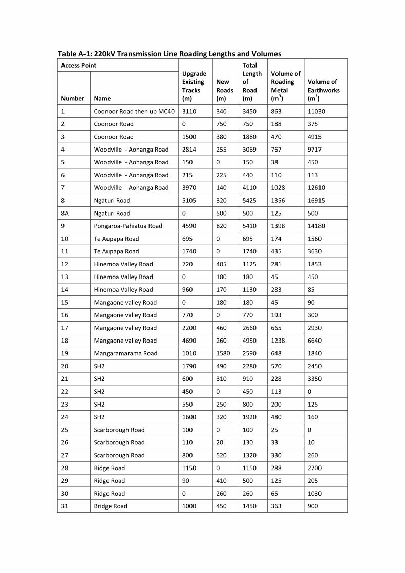
Table A‐1: 220kV Transmission Line Roading Lengths and Volumes
Access Point Upgrade Existing Tracks (m)
New Roads (m)
Total Length of Road (m)
Volume of Roading Metal (m3)
Volume of Earthworks (m3) Number Name
1 Coonoor Road then up MC40 3110 340 3450 863 11030
2 Coonoor Road 0 750 750 188 375
3 Coonoor Road 1500 380 1880 470 4915
4 Woodville ‐ Aohanga Road 2814 255 3069 767 9717
5 Woodville ‐ Aohanga Road 150 0 150 38 450
6 Woodville ‐ Aohanga Road 215 225 440 110 113
7 Woodville ‐ Aohanga Road 3970 140 4110 1028 12610
8 Ngaturi Road 5105 320 5425 1356 16915
8A Ngaturi Road 0 500 500 125 500
9 Pongaroa‐Pahiatua Road 4590 820 5410 1398 14180
10 Te Aupapa Road 695 0 695 174 1560
11 Te Aupapa Road 1740 0 1740 435 3630
12 Hinemoa Valley Road 720 405 1125 281 1853
13 Hinemoa Valley Road 0 180 180 45 450
14 Hinemoa Valley Road 960 170 1130 283 85
15 Mangaone valley Road 0 180 180 45 90
16 Mangaone valley Road 770 0 770 193 300
17 Mangaone valley Road 2200 460 2660 665 2930
18 Mangaone valley Road 4690 260 4950 1238 6640
19 Mangaramarama Road 1010 1580 2590 648 1840
20 SH2 1790 490 2280 570 2450
21 SH2 600 310 910 228 3350
22 SH2 450 0 450 113 0
23 SH2 550 250 800 200 125
24 SH2 1600 320 1920 480 160
25 Scarborough Road 100 0 100 25 0
26 Scarborough Road 110 20 130 33 10
27 Scarborough Road 800 520 1320 330 260
28 Ridge Road 1150 0 1150 288 2700
29 Ridge Road 90 410 500 125 205
30 Ridge Road 0 260 260 65 1030
31 Bridge Road 1000 450 1450 363 900

32 Makomako Road 2340 810 3150 788 405
33 Makomako Road 0 190 190 48 95
34 Makomako Road 2520 1660 4180 1045 10550
35 Makomako Road 0 580 580 145 740
36 Makomako Road 0 520 520 130 260
37 South Range Road 0 1050 1050 263 975
38 South Range Road 350 170 520 130 1135
39 South Range Road 0 10 10 3 5
40 South Range Road 0 130 130 33 65
41 South Range Road 0 50 50 13 25
42 South Range Road 0 290 290 73 145
43 South Range Road 0 80 80 20 40
44 South Range Road 0 410 410 103 205
45 South Range Road 0 340 340 85 170
46 South Range Road 0 230 230 58 115
47 South Range Road 0 100 100 25 50
Totals 47689 16615 64304 16121 116352

Appendix B: Transmission Line – Construction Vehicle Traffic Volumes

Table B‐1: 220kV Transmission Line Traffic Volumes
Access Point Total Volume of Traffic
Peak Volumes of Traffic (During road construction)
Number Name Trucks (No.)
Cars (No.)
No. of Trucks per Day
No. of Cars per Day
Duration of Peak (Days)
1 Coonoor Road then up MC40 821 1947 19 12 14
2 Coonoor Road 140 259 21 12 3
3 Coonoor Road 441 981 19 12 8
4 Woodville ‐ Aohanga Road 575 1261 20 12 12
5 Woodville ‐ Aohanga Road 96 230 20 12 1
6 Woodville ‐ Aohanga Road 117 244 21 12 2
7 Woodville ‐ Aohanga Road 626 1311 18 12 17
8 Ngaturi Road 994 2042 19 12 22
8A Ngaturi Road 60 150 20 12 2
9 Pongaroa‐Pahiatua Road 1001 2041 19 12 22
10 Te Aupapa Road 136 256 20 12 3
11 Te Aupapa Road 286 529 20 12 7
12 Hinemoa Valley Road 288 722 18 12 5
13 Hinemoa Valley Road 97 231 22 12 1
14 Hinemoa Valley Road 167 277 19 12 5
15 Mangaone valley Road 73 231 22 12 1
16 Mangaone valley Road 148 260 22 12 3
17 Mangaone valley Road 384 796 19 12 11
18 Mangaone valley Road 617 1351 19 12 20
19 Mangaramarama Road 426 1015 20 12 10
20 SH2 356 778 20 12 9
21 SH2 175 489 19 12 4
22 SH2 117 244 21 12 2
23 SH2 166 484 22 12 3
24 SH2 249 538 19 12 8
25 Scarborough Road 67 228 17 12 1
26 Scarborough Road 69 229 19 12 1
27 Scarborough Road 228 509 21 12 5
28 Ridge Road 144 278 19 12 5
29 Ridge Road 128 247 23 12 2
30 Ridge Road 127 458 27 12 1
31 Bridge Road 167 292 19 12 6
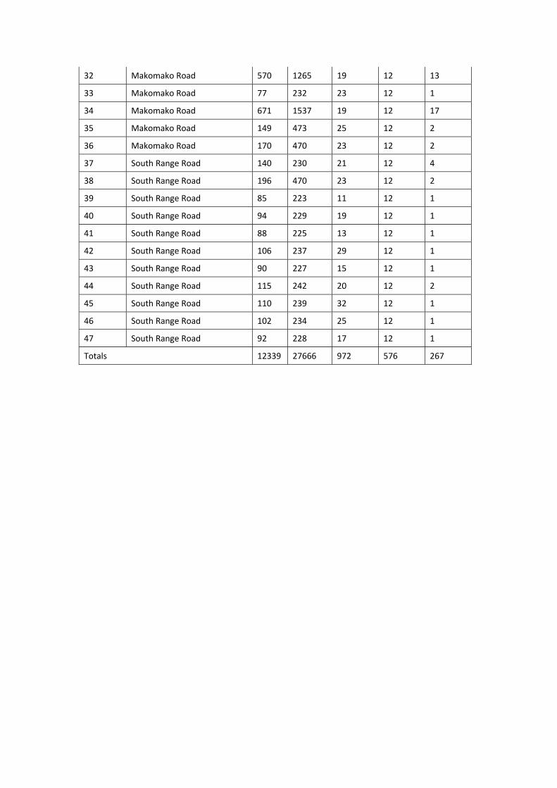
32 Makomako Road 570 1265 19 12 13
33 Makomako Road 77 232 23 12 1
34 Makomako Road 671 1537 19 12 17
35 Makomako Road 149 473 25 12 2
36 Makomako Road 170 470 23 12 2
37 South Range Road 140 230 21 12 4
38 South Range Road 196 470 23 12 2
39 South Range Road 85 223 11 12 1
40 South Range Road 94 229 19 12 1
41 South Range Road 88 225 13 12 1
42 South Range Road 106 237 29 12 1
43 South Range Road 90 227 15 12 1
44 South Range Road 115 242 20 12 2
45 South Range Road 110 239 32 12 1
46 South Range Road 102 234 25 12 1
47 South Range Road 92 228 17 12 1
Totals 12339 27666 972 576 267
Top Related