Wireless power transmission using technologies other … · Wireless power transmission using...
79
Report ITU-R SM.2303-1 (06/2015) Wireless power transmission using technologies other than radio frequency beam SM Series Spectrum management
Transcript of Wireless power transmission using technologies other … · Wireless power transmission using...
Report ITU-R SM.2303-1 (06/2015)
Wireless power transmission using technologies other
than radio frequency beam
SM Series
Spectrum management

ii Rep. ITU-R SM.2303-1
Foreword
The role of the Radiocommunication Sector is to ensure the rational, equitable, efficient and economical use of the
radio-frequency spectrum by all radiocommunication services, including satellite services, and carry out studies without
limit of frequency range on the basis of which Recommendations are adopted.
The regulatory and policy functions of the Radiocommunication Sector are performed by World and Regional
Radiocommunication Conferences and Radiocommunication Assemblies supported by Study Groups.
Policy on Intellectual Property Right (IPR)
ITU-R policy on IPR is described in the Common Patent Policy for ITU-T/ITU-R/ISO/IEC referenced in Annex 1 of
Resolution ITU-R 1. Forms to be used for the submission of patent statements and licensing declarations by patent
holders are available from http://www.itu.int/ITU-R/go/patents/en where the Guidelines for Implementation of the
Common Patent Policy for ITU-T/ITU-R/ISO/IEC and the ITU-R patent information database can also be found.
Series of ITU-R Reports
(Also available online at http://www.itu.int/publ/R-REP/en)
Series Title
BO Satellite delivery
BR Recording for production, archival and play-out; film for television
BS Broadcasting service (sound)
BT Broadcasting service (television)
F Fixed service
M Mobile, radiodetermination, amateur and related satellite services
P Radiowave propagation
RA Radio astronomy
RS Remote sensing systems
S Fixed-satellite service
SA Space applications and meteorology
SF Frequency sharing and coordination between fixed-satellite and fixed service systems
SM Spectrum management
Note: This ITU-R Report was approved in English by the Study Group under the procedure detailed in
Resolution ITU-R 1.
Electronic Publication
Geneva, 2015
ITU 2015
All rights reserved. No part of this publication may be reproduced, by any means whatsoever, without written permission of ITU.

Rep. ITU-R SM.2303-1 1
REPORT ITU-R SM.2303-1
Wireless power transmission using technologies
other than radio frequency beam
(2014-2015)
TABLE OF CONTENTS
Page
1 Introduction .................................................................................................................... 2
2 Applications developed for use of WPT technologies ................................................... 2
2.1 Portable and mobile devices ............................................................................... 2
2.2 Home appliance and logistics applications ......................................................... 3
2.3 Electric vehicle ................................................................................................... 3
3 Technologies employed in or incidental to WPT applications ....................................... 4
3.1 For portable and mobile devices ......................................................................... 4
3.2 For home appliances ........................................................................................... 6
3.3 For electrical vehicles ......................................................................................... 7
4 WPT’s standardization situation in the world ................................................................ 10
4.1 National standards development organizations .................................................. 10
4.2 International organizations ................................................................................. 12
5 Status of spectrum .......................................................................................................... 19
5.1 WPT, distinction between industrial, scientific and medical and short range
device bands ........................................................................................................ 19
5.2 Non-ISM bands used on a national basis for WPT ............................................. 20
5.3 ISM bands used on a national basis for WPT ..................................................... 21
6 Status of national regulation ........................................................................................... 24
7 Status of co-existence studies between WPT and radiocommunication services,
including the radio astronomy service ............................................................................ 33
8 WPT human hazards ....................................................................................................... 42
9 Summary ......................................................................................................................... 42
10 References ...................................................................................................................... 43
Annex 1 – RF exposure assessment methodologies ................................................................ 44
Annex 2 – Implementation example of the use of the 6 765-6 795 kHz ISM band
for wireless charging of mobile devices ......................................................................... 49
Annex 3 – Measurement data of radiated noise and conductive noise from WPT systems .... 52
2 Rep. ITU-R SM.2303-1
1 Introduction
This Report refers to frequency ranges and associated potential levels for out-of-band emissions
which have not been agreed within the ITU-R, and require further study to ascertain if they provide
protection to radiocommunication services on co-channel, adjacent channel and adjacent band
criteria. The Report gives an overview of current research and development and work being
undertaken in some Regions.
Technologies to transmit electric power wirelessly have been developed since the 19th century,
beginning from induction technology. Since the Massachusetts Institute of Technology innovation
on Non-Beam wireless power technology in 2006, technologies of wireless power transmission
(WPT) under development vary widely; e.g. transmission via radio-frequency beam, magnetic field
induction, resonant transmission, etc. WPT applications are expanding to mobile and portable
devices, home appliances and office equipment, and electric vehicles. New features such as freedom
of charging device placement are added. Some technology claims simultaneous multiple device
charging. Inductive WPT technologies are widely commercially available today. Nowadays,
resonant WPT technologies are coming out to consumer market. Automotive industry looks at WPT
for electric vehicle (EV) applications in the upcoming future.
Suitable frequencies for WPT to attain required transmission power level and power efficiency,
applicable physical dimensions of coil/antenna are mostly specified. However, WPT coexistence
study with the incumbent radio systems are now carefully examined and is pointed out with many
issues which should be resolved in a timely manner. Some countries and international radio-related
organizations are discussing radio regulations necessary to introduce WPT technologies. Some
discussion results and ongoing discussions are now publicly available to share.
For example, APT Survey Report on WPT [1] and APT Report on WPT [9] provide the latest
information on regulatory discussions in Asia-Pacific Telecommunity (APT) member countries on
WPT to consider introduction.
This Report provides information about WPT using technologies other than radio frequency beam,
as partial answers to Question ITU-R 210-3/1.
This Report includes information about national regulations but this information has no
international regulatory effect.
2 Applications developed for use of WPT technologies
2.1 Portable and mobile devices
2.1.1 Inductive WPT for mobile devices such as cellular phones and portable multimedia
devices
Inductive WPT uses inductive technologies and is applied to the following applications:
– mobile and portable devices: cellular phones, smartphones, tablets, note-PCs;
– audio-visual equipment: digital still cameras;
– business equipment: handy-digital-tools, table-order-systems;
– others: lighting equipment (e.g. LED), robots, toys, car-mounted devices, medical
equipment, healthcare devices, etc.
Some technologies of this type may require exact device positioning on the power source.
In general, the device to be charged should be contacted with the power source such as the power
tray. Operational emission power is assumed in the range from several watts to 10 s of watts.

Rep. ITU-R SM.2303-1 3
2.1.2 Resonant WPT for mobile devices such as cellular phones and portable multimedia
devices such as smartphones, tablets, portable multimedia devices
Resonant WPT uses resonant technologies, have more spatial freedom than inductive technology. The technology is applied to the following applications for any orientation (x-y and z) with no alignment techniques:
– cellular phones, smartphones, tablets, note-PCs, wearable devices;
– digital still cameras, digital video cameras music-players, portable TVs;
– handy-digital-tools, table-order-systems, lighting equipment (e.g. LED), robots, toys, car-mounted devices, medical equipment, healthcare devices, etc.
Annex 2 describes an example of this type of WPT technology.
2.2 Home appliance and logistics applications
This application may require similar features and aspects to WPT for portable and multimedia devices. However, in general they use higher power than those. Therefore, it may require additional regulatory compliance in some countries.
As operation power of CE appliances such TV with big video screen increases, WPT for these products require higher charging power above 100 W which may not obtain certification in the current regulatory categories and radio policies in some countries.
Magnetic induction and magnetic resonance methods can be applied according to the type of home and logistics applications of WPT. The applications are as follows:
– Home appliance applications: Household electrical appliances, furniture, cooker, mixer, television, small robot, audio-visual equipment, lighting equipment, healthcare devices, etc.
– Logistics applications: stocker at logistics warehouse, medical equipment, Overhead Transfer at LCD and Semiconductor product lines, Automated Guided Vehicle (AGV) system etc.
The operation power is expected to be from several hundreds of watts to several kW range due to the consumption power of application devices. Suitable frequency band is under 6 780 kHz in considering the RF emission, exposure, and system performance.
2.3 Electric vehicle
A concept of WPT for EV including plug-in hybrid electric vehicle (PHEV) is to charge the car without a power-cable wherever WPT is available.
Charging power may depend on the requirement of the users. In most use cases for passenger vehicles at their home garage, 3.3 kW or equivalent charring power could be accepted. However, some users want to charge quickly or their car for specific use purpose may need much bigger power. 20 kW or higher power range are also taken in consideration today.
Charging power may depend on the requirement of the heavy duty vehicles. In use cases for heavy duty vehicles, the initial 75 kW equivalent charging power may be required. The 100 kW or higher power range are also taken into consideration.
Were WPT for EV to become a ubiquitous power source, it may lead to a reduction of EV battery size and unlimited drive.
Charged power at car will be used for driving, powering supplemental car devices, air-conditioning, and other car-necessities.
WPT technologies and applications both while parking and while driving are taken into consideration.
4 Rep. ITU-R SM.2303-1
3 Technologies employed in or incidental to WPT applications
3.1 For portable and mobile devices
3.1.1 Magnetic induction WPT technology
The WPT by magnetic inductance is a well-known technology, applied for a very long time in
transformers where primary and secondary coils are inductively coupled, e.g. by the use of a shared
magnetic permeable core. Inductive power transmission through the air with primary and secondary
coils physically separated is also a known technology for more than a century, also known as
Tightly Coupled WPT. A feature of this technology is that the efficiency of the power transmission
drops if the distance through the air is larger than the coil diameter and if the coils are not aligned
within the offset distance. The efficiency of the power transmission depends on the coupling
factor (k) between the inductors and their quality (Q). This technology can achieve higher
efficiency than magnetic resonance method. This technology has been commercialized for charging
of smart phones. With a coil array, this technology also offers flexibility in the receiver coil location
of the transmitter.
FIGURE 3.1
Example magnetic induction WPT system block diagram
R p 1e ort SM.2303-3-0
Base station Mobile device
Transmitter
Control Comm.
Modulation
Power conversion
ControlControl Comm.
Power conversion
SY
ST
EM
LO
AD
Power
Message
Backscatter modulation
Receiver
Transmitter Receiver
Modulation
Load
Power
3.1.2 Magnetic resonance WPT technology
The WPT by magnetic resonance is also known as Loosely Coupled WPT. The theoretical basis of
this magnetic resonance method was first developed in 2005 by Massachusetts Institute of
Technology, and their theories were validated experimentally in 2007 [3]. The method uses a coil
and capacitor as a resonator, transmitting electric power through the electromagnetic resonance
between transmitter coil and receiver coil (magnetic resonant coupling). By matching the resonance
frequency of both coils with high Q factor, electric power can be transmitted over a long distance
where magnetic coupling between two coils is low. The magnetic resonance WPT can transmit
electric power over a range of up to several meters.
This technology also offers flexibility in the receiver coil location of the transmission coil. Practical
technical details can be found in many technical papers, for example, those in [3] and [4].

Rep. ITU-R SM.2303-1 5
FIGURE 3.2
Example magnetic resonance WPT system block diagram
R pe ort SM.2303-3-02
Rx resonator Power receiving unit (PRU)
Rectifier
Voltagecontrol
Matchingcircuit
Tx resonator
Poweramp
Powersupply
DC to DC
Power transmitting unit (PTU)
MCU andout-band
signalling
Clientdeviceload
MCU andout-band
signalling
Resonantcoupling@ 6.78 MHz
Bidirectionalcommunication@ 2.4 Ghz band
3.1.3 Capacitive coupling WPT
The capacitive coupling WPT system has two sets of electrodes, and does not use coils as magnetic
type of WPT systems. Power is transmitted via an induction field generated by coupling the two
sets of electrodes. The capacitive coupling system has some merits as follows. Figures 3.3 and 3.4
show system block diagram and typical structure, respectively.
1) Capacitive coupling system provides horizontal position freedom with an easy-to-use
charging system for end customers.
2) Very thin (less than 0.2 mm) electrode can be used between transmitter and receiver in the
system, and hence suitable for integration into slim mobile devices.
3) No heat generation in the wireless power transmission area. This means the temperature
does not rise in the wireless power transmission area, which protects the battery from
heating even when the unit is placed nearby.
4) The emission level of the electric field is low because of the structure of its coupling
system. The electric field is emitted from electrodes for power transmission.
6 Rep. ITU-R SM.2303-1
FIGURE 3.3
Capacitive coupling WPT system block diagram
R pe ort SM.2303-3-03
Ac adaptor
DC input
Return
Target device
Downtransformer
DC output
Overvoltageprotection
Controller
Uptransformer
Inverter(amplifier)
Transmission module
Electrode
Electrode
Power transmission
Rectifyingcircuit
Voltageregulator
Receiver module
PWM
PWM
FIGURE 3.4
Typical structure of the capacitive coupling system
R pe ort SM.2303-3-04
BatteryReceivermodule
GND electrode
Electrodes forpower transmission
Electric field
Wireless charger
GND electrode
Transmissionmodule
Mobile device
3.2 For home appliances
Inductive power sources (transmitters) may stand alone or be integrated in the kitchen counter tops
or dining tables. These transmitters could combine the WPT to an appliance with conventional
inductive heating.
For the home appliance application, the power level is usually up to several kilowatts, and the load
maybe motor-driven or heating type. Future products will support more than 2 kW power and some
new design proposal for cordless kitchen appliances is being investigated.
Considering the high power usage in home, frequencies in the order of tens of kHz are preferred to
restrict electromagnetic exposure to human bodies. And high reliable devices such as IGBTs are
usually used and these devices are working in 10-100 kHz frequency range.
The product applied in the kitchen must meet the safety and electromagnetic field (EMF)
requirements. And it is a key issue that transmitter should be light and small size to fit the kitchen in
addition to being low cost. The distance between the transmitter and the receiver is intended to be
less than 10 cm.

Rep. ITU-R SM.2303-1 7
The following pictures show examples of wireless power kitchen appliances that will come to the
market soon.
FIGURE 3.5
Wireless power kitchen appliances
R pe ort SM.2303-3-05
Tightly coupled mixer Tightly coupled rice cooker
WPT systems are already integrated in the product lines of Semiconductor and LCD panel, the
following pictures show examples.
FIGURE 3.6
Use cases of the LCD and semiconductor product lines and kitchen WPT systems
R pe ort SM.2303-3-06
(WPT overhead shutter ofLCD product line)
(WPT overhead transmissionof Semiconductor product line)
(WPT kitchen island ofapartment)
3.3 For electrical vehicles
Magnetic Field Wireless Power Transmission (MF-WPT) is one of the focus points in
standardization discussion such as IEC PT61980 and SAE J2954TF regarding WPT for EV
including PHEV though there are several types of WPT methods. MF-WPT for EV and PHEV
contains both inductive type and magnetic resonance type. Electric power can be transmitted from
the primary coil to the secondary coil efficiently via magnetic field by using resonance between the
coil and the capacitor.
Expected passenger vehicle applications assume the following aspects:
1) WPT application: Electric power transmission from electric outlet at a residence and/or
public electric service to EVs and PHEVs.
2) WPT usage scene: at residential, apartment, public parking, etc.
3) Electricity use in vehicles: All electric systems such as charging batteries, computers, air
conditioners, etc.

8 Rep. ITU-R SM.2303-1
4) Examples of WPT usage scene. An example for passenger vehicles is shown in the
following figure.
5) WPT method: AWPT system for EV/PHEV has at least two coils. One is in the primary
device and the other is in the secondary device. The electric power will be transmitted from
primary device to secondary device through magnetic flux/field.
6) Device location (Coil location):
a) Primary device: on ground or/and in ground.
b) Secondary device: lower surface of vehicle.
7) Air gap between primary and secondary coils: Less than 30 cm.
8) Transmission power class example: 3 kW, 6 kW, and, 20 kW.
9) Safety: primary device can start power transmission only if secondary device is located in
the proper area for WPT. Primary device needs to stop transmission if it is difficult to
maintain safe transmission.
FIGURE 3.7
Example of a WPT system for EV/PHEV
R pe ort SM.2303-3-07
RectifierBattery
Secondary coil
Primary coil
LFpowersupply
Ac in
Secondary coil
Primary coil
Magnetic field
Capacitor
Capacitor
Secondary coil
Primary coil
Simulation result of magnetic field around WPT system
Wireless communication for control
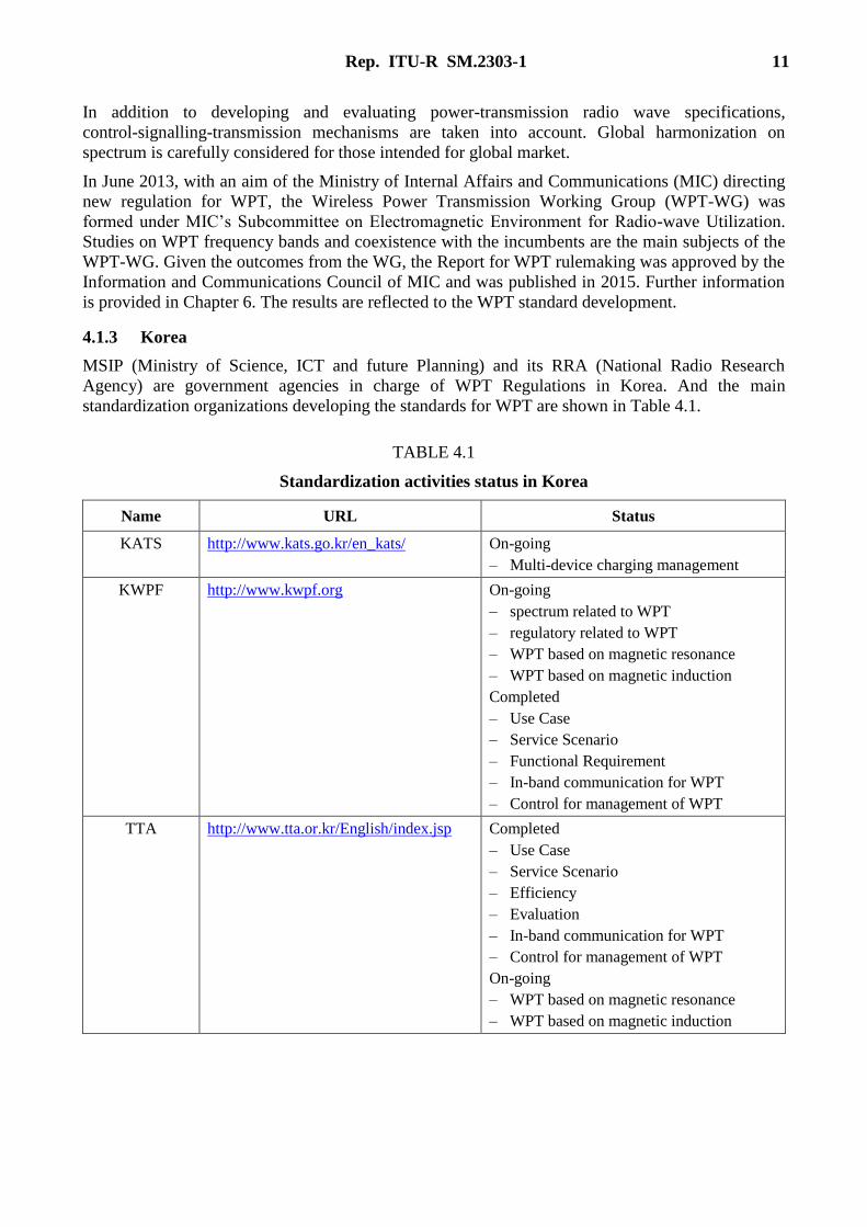
In order to run heavy duty vehicles such as an electrical bus, the infrastructure of the system is to
embed electric strips in roadbeds that magnetically transmit energy to battery-powered vehicles
above. The bus can move along the electrical strips without any stopping for charging its power,
known as on-line electric vehicle (OLEV). Furthermore the bus can be charged a stopping condition
in bus stop or bus garage. The online bus at an amusement park or at the city is the first system
operated in the form of EV for heavy duty vehicles in the world.
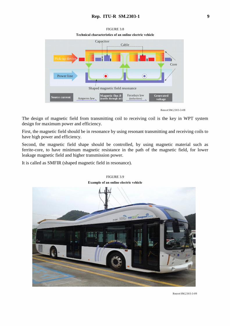
Rep. ITU-R SM.2303-1 9
FIGURE 3.8
Technical characteristics of an online electric vehicle
R pe ort SM.2303-3-08
Pick-up device
Core
Magnetic flux B(travels through air)
Shaped magnetic field resonance
Amperes law
CapacitorCable
Power line
Source currentGenerated
voltage
Faradays law(induction)
The design of magnetic field from transmitting coil to receiving coil is the key in WPT system
design for maximum power and efficiency.
First, the magnetic field should be in resonance by using resonant transmitting and receiving coils to
have high power and efficiency.
Second, the magnetic field shape should be controlled, by using magnetic material such as
ferrite-core, to have minimum magnetic resistance in the path of the magnetic field, for lower
leakage magnetic field and higher transmission power.
It is called as SMFIR (shaped magnetic field in resonance).
FIGURE 3.9
Example of an online electric vehicle
R pe ort SM.2303-3-09

10 Rep. ITU-R SM.2303-1
4 WPT’s standardization situation in the world
4.1 National standards development organizations
4.1.1 China
In China, CCSA (China Communication Standard Association) has been creating WPT standards
for portable devices, such as Mobile Stations. In 2009, CCSA TC9 set up one new research report
project “Research on Near-field Wireless Power Supply Technology”. This project was finished in
March, 2012 and developed the report on the wireless power supply technology research. In 2011,
CCSA TC9 created two standard projects: (1) Electromagnetic field (EMF) Evaluation Methods for
Wireless Power Supply (WPS); (2) Electromagnetic compatibility (EMC) Limits and Measurement
Methods for WPS. These two standards will be published soon.
Now, there are three new standards related to the technical requirements and test methods
(Part 1: General; Part 2: Tightly Coupled; Part 3: Resonance wireless power) and the development
of safety requirements have been in the final draft status. More and more standard projects related
to wireless power transmission will be created. The target products are audio, video and multimedia
devices, information technology equipment, and telecommunication devices.
These standards focus on performance, radio spectrum, and interface. It is planned that this standard
will not involve intellectual property rights. Generally, the possibility for these standards to become
mandatory is low.
The standards may define new logos to identify which Part of standard (Parts 2/3) the product
belongs to.
China National Standardization Administration Commission (SAC) is planning to set up a National
Standardization Technical Committee (TC) on WPS. China Academy of Telecommunication
Research (CATR) of MIIT has been promoting it. This TC is responsible for creating national
standards on WPS for mobile phones, information technology equipment, audio, video and
multimedia devices.
Considering the plan and/or timeline of standard/guideline/regulation development at CCSA, EMC
and EMF standards will be published soon. Part 1 of the Technical requirements standards has been
approved, and Part 2, Part 3 and safety requirements standards will be completed in 2014.
In China, a national SDO oriented to wireless-powered home appliance was set up in
November 2013 and it has a plan to make the national standards. Moreover, other issues such as
safety and performances are also discussed there.
4.1.2 Japan
The WPT-Working Group of BWF (Broadband Wireless Forum, Japan) is taking responsibility for
drafting WPT technical standards utilizing the ARIB (Association of Radio Industries and
Businesses) drafting protocols. A draft standard developed by BWF will be sent to ARIB for
approval. BWF performed in-depth technical study for WPT spectrum for all the applications and
technologies. Currently, the following WPT technologies are put in pipeline with timelines for
standardization. The first three with less than 50 W transmission power are intended for approvals
in 2015.
– Capacitive coupling WPT.
– WPT using microwave two-dimensional waveguide sheet.
– Magnetic resonant WPT using 6 765-6 795 kHz for mobile/portable devices.
– Magnetic resonant WPT for home appliances and office equipment.
– WPT for EV/PHEV.
Rep. ITU-R SM.2303-1 11
In addition to developing and evaluating power-transmission radio wave specifications,
control-signalling-transmission mechanisms are taken into account. Global harmonization on
spectrum is carefully considered for those intended for global market.
In June 2013, with an aim of the Ministry of Internal Affairs and Communications (MIC) directing
new regulation for WPT, the Wireless Power Transmission Working Group (WPT-WG) was
formed under MIC’s Subcommittee on Electromagnetic Environment for Radio-wave Utilization.
Studies on WPT frequency bands and coexistence with the incumbents are the main subjects of the
WPT-WG. Given the outcomes from the WG, the Report for WPT rulemaking was approved by the
Information and Communications Council of MIC and was published in 2015. Further information
is provided in Chapter 6. The results are reflected to the WPT standard development.
4.1.3 Korea
MSIP (Ministry of Science, ICT and future Planning) and its RRA (National Radio Research
Agency) are government agencies in charge of WPT Regulations in Korea. And the main
standardization organizations developing the standards for WPT are shown in Table 4.1.
TABLE 4.1
Standardization activities status in Korea
Name URL Status
KATS http://www.kats.go.kr/en_kats/ On-going
– Multi-device charging management
KWPF http://www.kwpf.org On-going
– spectrum related to WPT
– regulatory related to WPT
– WPT based on magnetic resonance
– WPT based on magnetic induction
Completed
– Use Case
– Service Scenario
– Functional Requirement
– In-band communication for WPT
– Control for management of WPT
TTA http://www.tta.or.kr/English/index.jsp Completed
– Use Case
– Service Scenario
– Efficiency
– Evaluation
– In-band communication for WPT
– Control for management of WPT
On-going
– WPT based on magnetic resonance
– WPT based on magnetic induction
12 Rep. ITU-R SM.2303-1
4.2 International organizations
Some international organizations dealing with WPT standardization and their relevant activities are
summarized in Table 4.2.
TABLE 4.2
WPT related international organizations
Name of
Organization Activities
CISPR (Comité
International Spécial
des Perturbations
Radioélectriques)
WPT is taken by CISPR SC-B (Interference relating to ISM radio frequency
apparatus, and to overhead power lines, etc.) for discussion. The other SCs are
considering WPT if they take.
SC-B formed a Task Force in June 2014 intended for specification development
IEC TC 100 Survey for Technical Reports regarding WPT
– IEC TC 100 Stage 0 Project
– Survey Completed: July 2012
– Under Drafting Technical Reports
IEC 61980
(IEC TC 69)
IEC TC 69 (Electric road vehicles and electric industrial trucks) WG4, together
with ISO TC22 (Road Vehicles), discusses WPT for automotive.
– IEC 61980-1: General Requirements
– IEC 61980-2: Communication
– IEC 61980-3: Magnetic Field Power Transfer
ISO 19363
(ISO (TC22/SC21))
ISO 19363: Magnetic field wireless power transfer – Safety and interoperability
requirements (publicly available specification, PAS)
– Established in early 2014
– Target is to develop a standard which specifies requirements for the vehicle-
side parts
– A close synchronization with IEC 61980 and SAE J2954
ISO/IEC JTC 1 SC 6 In-band PHY and MAC Layer Protocol of WPT
– ISO/IEC JTC 1 SC 6 – Working Item was approved in Jan. 2012.
– On Circulation with WD (Working Document)
CEA (Consumer
Electronics
Association)
CEA R6-TG1 (Wireless Charging Task Group) discusses WPT and related issues
SAE (Society of
Automotive
Engineers)
WPT standardization has been getting active since 2010. Proposed specifications
by OEMs are reviewed. Standardization is to complete in 2013-2014 as IEC
plans. Currently specific frequency bands selection is under consideration for
future decision. In November 2013, SAE International J2954™ Task Force for
Wireless Power Transfer (WPT) of Light Duty, Electric and Plug-in Electric
Vehicles, agreed on “85 kHz band” operation and three power classes for light
duty vehicles

Rep. ITU-R SM.2303-1 13
TABLE 4.2 (end)
Name of
Organization Activities
A4WP Non-radiative near- and mid-range magnetic resonant coupling (highly resonant
coupling) (loosely-coupled WPT).
– Baseline Technical Specification completed 2012
– Released its technical specification (ver.1) in January 2013
WPC Tightly coupled inductive coupling solutions across a range of power levels.
Website lists more than 120 members and 80 certified products including
accessories, chargers and devices
– Released technical specification (ver.1) in July 2010
CJK WPT WG The working group on WPT of the CJK Information Technology Meeting.
Shares information in the region to study and survey on low power and high
power WPT
– Released CJK WPT Technical Report 1 in April 2013
– To release CJK WPT Technical Report 2 in Spring 2014
– Released CJK WPT Technical Report 3 in May 2015
4.2.1 IEC CISPR
From a regulatory point of view IEC CISPR can distinguish WPT applications into:
a) WPT applications offering wireless power transmission at a particular operating frequency
without additional data transmission.
b) WPT applications also using the WPT frequency (band) for additional data transmission or
communications with the secondary device.
c) WPT applications using other frequencies than those used for WPT for additional data
transmission or communications with the secondary device.
From CISPR perspective (protection of radio reception) there is however no need to distinguish into
WPT applications a) or b). In both cases, the radio frequency interference (RFI) potential of such
WPT applications will be dominated by their primary function only, i.e. by the wireless power
transmission at the given frequency (or within the given frequency band).
Since CISPR standards offer already complete sets of limits and measurement methods for control
of wanted, unwanted and spurious emissions from WPT applications according to item a) or b) we
are convinced that it suffices just to continue in applying these standards. Clearly these standards
might be employed in regulations concerning general EMC for electric and electronic products,
as e.g. for ISM applications.
For WPT applications according to item c) above, existing regulations concerning general EMC
should continue in application to the primary WPT function (inclusive of additional data
transmission, if any, according to item b) above. Independently, further radio regulations may apply
to any radio data transmission or communications at frequencies different from the WPT frequency.
In this case, other EMC and functional standards for radio equipment may have to be taken into
account too. An assessment of the total RFI potential of WPT applications according to item c)
above in respect of the protection of radio reception in general and in respect of
compatibility/coexistence with other radio appliances or services should always be done.
This assessment should be comprised of the application of the respective CISPR standard and EMC
and functional standard(s) for the radio communications components or modules of the WPT
system.

14 Rep. ITU-R SM.2303-1
The normal way to apply these standards will be to use them for type testing. Dependent on national
or regional regulation, the results of such type test may be used then as basis for an approval of the
type by a type approval authority, or for other kinds of conformity assessment and declaration.
A proposal of CISPR for classification of power electronic equipment offering WPT and for use of
CISPR EMC emission standards in regional and/or national regulation is found in Table 4.3.
The proposal is also valid for WPT applications within the scopes of CISPR 14-1 (household
appliances, electric tools and similar apparatus), CISPR 15 (lighting equipment) and CISPR 32
(multimedia and broadcast receiver equipment). For them, reference to CISPR 11 (ISM equipment)
is to be replaced by reference to these relevant CISPR standards.
CISPR is about to extend applicability of the requirements for power electronic WPT equipment in
the scope of CISPR 11, with appropriate adjustments at some point in the future, to WPT
applications in the scopes of CISPR 14-1, CISPR 15 and CISPR 32. For the time being, only CISPR
11 offers a complete set of emission requirements for type tests on WPT applications, in the range
150 kHz up to 1 GHz, or up to 18 GHz, respectively.
CISPR is aware in a common gap in its CISPR standards, in control of conducted and radiated
disturbances from WPT equipment in the range 9 kHz to 150 kHz. Controlling these emissions is an
essential issue if the WPT equipment in question actually uses fundamental or operation frequencies
allocated in this frequency range.
Just for information: CISPR/B agreed to clarify the group 2 classification in CISPR 11 to cover
WPT equipment as follows:
Group 2 equipment: group 2 contains all ISM RF equipment in which radio-frequency
energy in the frequency range 9 kHz to 400 GHz is intentionally generated and used or only
used, in the form of electromagnetic radiation, inductive and/or capacitive coupling, for the
treatment of material, for inspection/analysis purposes, or for transmission of
electromagnetic energy.
This modified definition is found in CISPR/B/598/CDV which was approved, during the National
Voting in 2014. It covers the project General Maintenance (GM) for CISPR 11 Ed. 5.1 (2010) and
will provide CISPR 11 Ed. 6.0. If finally approved, this 6th Edition of CISPR 11 will be published
in summer 2015. It will cover:
a) the extended and accomplished definition for group 2 equipment also comprising any type
of power electronic WPT product;
b) the set of essential emission limits and measurement methods agreed so far for performance
of type tests on power electronic WPT products.
Please note that CISPR standards consist of the combination of suitable methods of measurement
and appropriate limits for permissible conducted and/or radiated disturbances in the applicable radio
frequency range. For group 2 equipment CISPR 11 presently specifies such requirements in the
range 150 kHz to 18 GHz. They also apply to all types of power electronic WPT equipment, for the
time being by default.
CISPR urgently recommends recognition of type test reports verifying compliance with these
CISPR emission requirements as Type Approval, for WPT applications with or without additional
data transmission or communications at the same WPT frequency (see also Cases 1 and 2 in
Table 4.3).

Rep. ITU-R SM.2303-1 15
TABLE 4.3
Recommendation of CISPR for classification of power electronic equipment offering wireless
power transmission (WPT) and for use of CISPR EMC emission standards
in regional and/or national regulation
Case Relevant
regulation
Other specifications
also used by regulators
Applicable essential
requirements/standards
EMF EMC Radio
1
WPT systems
without data
transfer or
communication
function
EMC
ITU-R RR
for ISM
appliances
Rec. ITU-R SM.1056-1 IEC 62311
(IEC 62479)
IEC/CISPR 11
Group 2
(or more
specific
IEC product
standard,
if available
N/A
2
WPT systems
with data
transfer or
communication
function
at same
frequency as
energy transfer
EMC
ITU-R RR
for ISM
appliances
Rec. ITU-R SM.1056-1 IEC 62311
(IEC 62479)
IEC/CISPR 11
Group 2
(or more
specific
IEC product
standard,
if available
Application
not
necessary
3
WPT systems
with data
transfer or
communication
function
at different
frequency to
energy transfer
EMC
ITU-R RR
for ISM
appliances
For final assessment of the RFI potential of the WPT function of the
power electronic WPT system, application of the rules for Case 1 resp.
Case 2 is recommended.
Efficient use
of the RF
spectrum
ITU-R RR
for radio
appliances
For final assessment of the (radio-based) signal/control and/or
communication function of the power electronic WPT system, national
and/or regional regulation (such as licensing and/or conformity
assessment) in respect of an efficient use of the radio frequency (RF)
spectrum may apply in addition. For type testing, adequate national or
regional standards for radio equipment, as e.g. according to Rep.
ITU-R SM.2153-1 (short-range radiocommunication devices),
may be used.
Case 3: If the WPT equipment operates with accompanying data transmission or communications
utilizing a frequency different from the frequency used for WPT, then:
a) compliance of the WPT function with the EMC emission requirements specified in the
relevant CISPR product standard should be deemed to establish presumption of conformity
with existing national and/or regional regulation on EMC according to
Recommendation ITU-R SM.1056-1, in respect of any wanted, unwanted and spurious
emissions resulting from WPT in the radio frequency range;
16 Rep. ITU-R SM.2303-1
b) compliance of the data transmission and/or communication function with the EMC and
functional requirements for radio equipment specified in national and/or regional
specifications and standards for control of the efficient use of the radio frequency spectrum
should be deemed to establish presumption of conformity with existing national and/or
regional regulation for radio devices or modules being part of the WPT system under test,
in respect of any wanted, unwanted and spurious emissions which can be attributed to the
radio data transmission and/or communications function.
In Case 3, the WPT system under test is regarded as multifunction equipment. An Approval of the
Type should be granted if it had been demonstrated that the respective type of WPT equipment
complies with the essential EMC emission (and immunity) requirements specified in the relevant
CISPR (or other IEC) standard(s), for its WPT function, see indent a). Another precondition for
granting the Type Approval should be that it had been demonstrated that the radio device or module
being integral part of the WPT systems complies with the essential EMC and functional
requirements for radio equipment specified in respective national or regional specifications and
standards for radio equipment.
For the time being CISPR observed ambivalent approaches of national and/or regional regulatory
authorities to the type approval, conformity assessment and licensing business in conjunction with
permission of operation and use of WPT applications in the field.
While European authorities could obviously imagine sole application of the European regulatory
framework for Short Range radio Devices (SRD) for Case 2, the Federal Communications
Commission (FCC) in the United States of America indicated that WPT devices operating at
frequencies above 9 kHz are to be regarded as intentional radiators and hence are subject to either
Part 15 and/or Part 18 of the FCC rules. The specific applicable rule part depends on how the device
operates, and if there is communication between the charger and the device being charged.
Table 4.4 contains an overview about present regulation in Europe. It should be noted that TCAM,
the Telecommunications Conformity Assessment and Market Surveillance Committee of the
European Commission approved these proposals offered by the European SDOs CENELEC and
ETSI, at its meeting in February 2013. In doing so TCAM indicated that current European
regulation applies to all present and upcoming types of WPT appliances.
For Case 2, Declarations of Conformity (DoCs) with sole reference to the EMC Directive will be
accepted for a type of power electronic WPT appliance with or without additional data transmission
at the WPT frequency, and with any rated throughput power, as long as it can be shown that the
WPT appliance meets the emission requirements for group 2 equipment specified in EN 55011
(see Case 2a). In addition Case 2b opens the possibility for a DoC solely referring the R&TTE
Directive, as long as it can be shown that the WPT appliance in question meets the requirements of
respective harmonized EMC and functional standards of ETSI for radio communications
equipment.

Rep. ITU-R SM.2303-1 17
TABLE 4.4
European regulation concerning EMC and efficient use of the radio frequency (RF) spectrum
(TCAM, CEPT/ERC, SDOs ETSI and CENELEC)
Case Relevant
regulation
Other specifications
also used by regulators
Applicable essential
requirements/standards
EMF EMC Radio
1
WPT systems
without data
transfer or
communication
function
EMC
Directive
None EN 62311
(EN 62479)
or other
applicable
standards
from
the OJEU
listed under
the Low
Voltage
Directive
EN 55011
Group 2
(or more
specific
CENELEC
standard,
if available)
N/A
2a
WPT systems
with data
transfer or
communication
function
at same
frequency as
energy transfer
(Any power
transfer rate)
EMC
Directive
None See above See above Application
not necessary
NOTE – For the time being, type tests on power electronic WPT equipment with or
without additional data transfer or communications at one and the same frequency in the
radio frequency range can be performed based on EN 55011. There is no constraint in
the rated throughput power, as long as it can be shown that the product type in question
meets the emission requirements specified in EN 55011.
It is expected that CENELEC starts closing the gap in the limits in EN 55011 for
conducted and radiated emissions in the range 9 kHz to 150 kHz, in particular for power
electronic WPT equipment using fundamental operation frequencies allocated in that
frequency range. It is also expected that CENELEC starts adapting emission limits for
WPT appliances in the other EMC product standards too.
2b
WPT systems
with data
transfer or
communication
function
at same
frequency as
energy transfer
(Limited power
transfer rate)
R&TTE
Directive
None EMF
standards
for radio
appliances
EMC standards
for radio
appliances
Functional
standards
for radio
appliances
9 kHz < band < 30 MHz EN 62311
(EN 62479)
EN 301 489-1/3 EN 300 330
30 MHz < band < 1 GHz EN 300 220
1 GHz < band < 40 GHz EN 300 440
NOTE – Where possible, the combination of the ETSI standards EN 301 489-1/3 and
a respective ETSI functional radio standard can be used for type tests on short range
radio devices (SRD) which provide both, WPT and radio data transfer or radio
communications at one and the same radio frequency.
Presently, possibility of type testing of SRDs with WPT functionality is still limited
to rather low rated power throughput levels. Work is on the way in ETSI to adapt
EN 300 330 for application in type testing of SRDs with WPT functionality and power
throughput rates in the range of up to a couple of tens of Watt.

18 Rep. ITU-R SM.2303-1
TABLE 4.4 (end)
Case Relevant
regulation
Other specifications
also used by regulators
Applicable essential
requirements/standards
EMF EMC Radio
3
WPT systems
with data
transfer or
communication
function
at different
frequency to
energy transfer
EMC
Directive
For final assessment of the RFI potential of the WPT function without or
with data transfer at the same frequency, the rules of Case 1, or of
Case 2a apply
R&TTE
Directive
(radio
communi-
cations
None EMF
standards
for radio
appliances
EMC standards
for radio
appliances
Functional
standards
for radio
appliances
9 kHz < band < 30 MHz EN 62311
(EN 62479)
EN 301 489-1/3 EN 300 330
30 MHz < band < 1 GHz EN 300 220
1 GHz < band < 40 GHz EN 300 440
NOTE – The combination of the ETSI standards EN 301 489-1/3 is just an example and
shall be used for type tests on SRD modules providing the data transfer and/or
communications function for the WPT product subject to the type test.
In principle any other kind of radio application fitting the purpose of local data and/or
radio communications in between the devices forming the local wireless power
transmission (WPT) system can be used. In this case, other combinations of harmonized
functional and EMC standards of ETSI apply, e.g. Bluetooth > EN 300 328 &
EN 301 489-1/17, dependent on the communication technology.
The CISPR, being interested in a harmonized way of worldwide proceedings with additional
regional or national regulation for WPT applications, recommends to adapting the approach
proposed in Cases 1, 2 and 3.
As noted above there is a gap in the essential emission requirements in CISPR 11, in the frequency
range 9-150 kHz. However, for the time being, the obvious gap was only confirmed for WPT power
electronic appliances in the scope of CISPR 11 which uses operation (or fundamental) frequencies
in the range below 150 kHz. Hence, if the limits are determined in the frequency range, they will
preferably apply to such WPT power electronic equipment only.
CISPR/B recommends application of the existing group 2 limits to any WPT power electronic
appliances. In proceeding this way CISPR/B does not identify any need to consult with ITU-R
about possible allocation of further ISM frequency bands.
4.2.2 ICNIRP
International Commission on Non‐Ionizing Radiation Protection (ICNIRP) levels are the reference
accepted worldwide, and countries’ threshold are compared to the ICNIRP exposure level.
This material refers to the relevant frequency bands of WPT. Additional material is found at
chapter 8.
ICNIRP has published guidelines on human exposure to electromagnetic fields. Two publications of
ICNIRP guidelines of 1998 [7] and 2010 [8] are applicable to WPT. Those guidelines describe basic
restrictions and reference levels. Limitations of exposure that are based on the physical quantities
directly related to the established health effects are termed basic restrictions. In the ICNIRP
guidelines, the physical quantity used to specify the basic restrictions on exposure to EMF is the
internal electric field strength, as it is the electric field that affects nerve cells and other electrically

Rep. ITU-R SM.2303-1 19
sensitive cells. However, the internal electric field strength is difficult to assess. Therefore, for
practical exposure assessment purposes, reference levels of exposure are provided.
Compliance with the reference level will ensure compliance with the relevant basic restriction.
If the measured or calculated value exceeds the reference level, it does not necessarily follow that
the basic restriction will be exceeded. However, whenever a reference level is exceeded it is
necessary to test compliance with the relevant basic restriction and to determine whether additional
protective measures are necessary. The ICNIRP reference levels on electric and magnetic fields
exposure are accepted worldwide, and countries’ threshold are compared to the ICNIRP reference
levels.
Operators of WPT may take steps to adequately protect the public from EMF effects.
Recent measurements of WPT H-field emissions related to RF exposure from Japan appear at
Annex 3. Additional measurements on field strengths nearby WPT are encouraged.
5 Status of spectrum
5.1 WPT, distinction between industrial, scientific and medical and short range device
bands
RR provisions of No. 1.15 – industrial, scientific and medical (ISM) applications (of radio
frequency energy): operation of equipment or appliances designed to generate and use locally radio
frequency energy for industrial, scientific, medical, domestic or similar purposes, excluding
applications in the field of telecommunications. The ISM RF bands are primarily for use by those
non-telecommunication applications. Therefore, WPT is SRD only if there are telecommunications
(for the data communication), such as Bluetooth or ZigBee. WPT is an intentional radiator.
The WPT energy transfer function is ISM: Industrial, Scientific, Medical; the data transfer is Short
Range Device. CISPR already suggested treating the WPT function separately to the
telecommunications function which could be SRD; see section 4.2 of Report ITU-R SM.2303.
Depending on national regulations, SRDs usually operate as un-licensed and un-protected ruling.
ITU Radio Regulations provisions Nos. 5.138 and 5.150 define the ISM RF bands. Candidate Short
Range Device (SRD) band is different than ISM band. Following Recommendation ITU-R
SM.1896 ‘Frequency ranges for global or regional harmonization of short-range devices (SRDs)’
Annexes 1 and 2, practically ISM band is sufficient condition but not obligatory for harmonized
SRD operation. All the ISM bands serve short range and electronic devices. However, SRDs
operate also at non-ISM bands. The ISM bands may serve WPT for the energy transfer; the SRD
bands may potentially serve as preferred RF for national, regional or global WPT use.
The following figure depicts the ISM bands in the different ITU Regions and non-ISM candidate
bands for SRDs in different Regions.
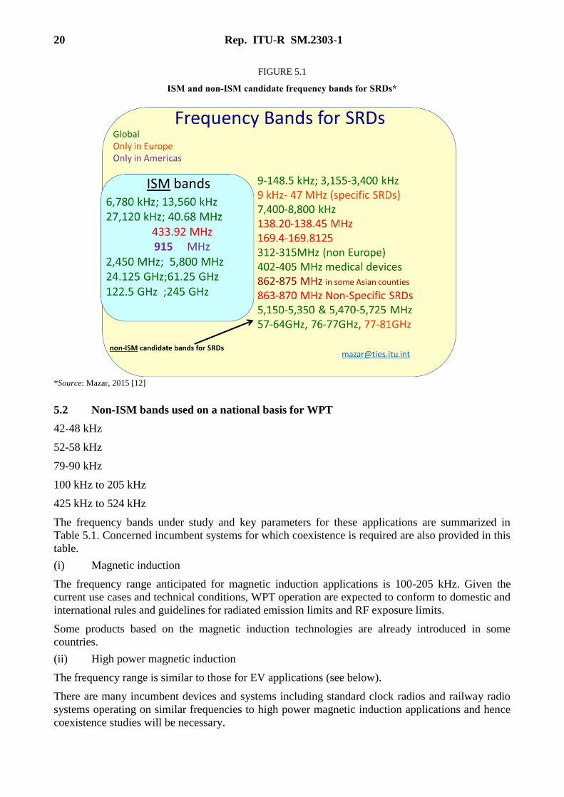
20 Rep. ITU-R SM.2303-1
FIGURE 5.1
ISM and non-ISM candidate frequency bands for SRDs*
*Source: Mazar, 2015 [12]
5.2 Non-ISM bands used on a national basis for WPT
42-48 kHz
52-58 kHz
79-90 kHz
100 kHz to 205 kHz
425 kHz to 524 kHz
The frequency bands under study and key parameters for these applications are summarized in
Table 5.1. Concerned incumbent systems for which coexistence is required are also provided in this
table.
(i) Magnetic induction
The frequency range anticipated for magnetic induction applications is 100-205 kHz. Given the
current use cases and technical conditions, WPT operation are expected to conform to domestic and
international rules and guidelines for radiated emission limits and RF exposure limits.
Some products based on the magnetic induction technologies are already introduced in some
countries.
(ii) High power magnetic induction
The frequency range is similar to those for EV applications (see below).
There are many incumbent devices and systems including standard clock radios and railway radio
systems operating on similar frequencies to high power magnetic induction applications and hence
coexistence studies will be necessary.
Rep. ITU-R SM.2303-1 21
(iii) Capacitive coupling
The capacitive coupling WPT systems are originally designed for the use of frequency range
425-524 kHz. Transmission power level is less than 100 W. Several reasons of the frequency
selection are provided as follows.
The first reason is to balance efficiency and equipment size. There are many parts designed for the
use in this band for example; inverters, rectifiers, etc., which lead to broader variety of components
with low loss performance that optimizes WPT equipment design. The transformers are key parts of
capacitive coupling WPT system. The transformer performance depends on the Q-value of ferrite
material, which can be optimized in this frequency range. Consequently, total efficiency of
capacitive coupling system is about 70% to 85%.
The second reason is capability to suppress unwanted emission in the electric field in order to
co-exist with the incumbents in the adjacent frequency bands such as AM broadcast. The spectrum
mask of capacitive coupling WPT systems in the frequency range 425-524 kHz was examined and
demonstrated to meet the coexistence conditions with AM broadcast and other services.
(iv) Electric Passenger Vehicles
In this Chapter, the word “EVs” means Electric Vehicles and Plug-in Hybrid Electric Vehicles
(PHEV).
WPT for EV while parked has been considered by BWF, IEC, SAE and JARI. It was commonly
agreed that the frequency range 20-200 kHz has advantages to achieve high energy transmission
efficiency in high power circuit design.
In Japan, the sub-bands; 42-48 kHz, 52-58 kHz, 79-90 kHz, 140.91-148.5 kHz were the focus of
spectrum sharing studies and coexistence talks related to incumbent applications. Intensive survey
of the current spectrum usage in the world was carried out to narrow down candidate spectrums so
that possible interference to the existing applications can be minimized. As of May 2015,
79-90 kHz range has been chosen for wireless EV charging. Similarly, SAE International J2954
Task Force agreed on 81.38-90.00 kHz for light duty vehicle WPT.
(v) Heavy duty electric vehicles
In May 2011, the Korean government allocated the frequencies for OnLine EV (OLEV) to 20 kHz
(19-21 kHz) and 60 kHz (59-61 kHz). These frequencies can be used for any type of vehicle
whether it is heavy duty or passenger vehicle in Korea. Now, OLEV system is in trial and licensed
at one site.
5.3 ISM bands used on a national basis for WPT
6 765-6 795 kHz
13.56 MHz
(i) Magnetic resonance
6 765-6 795 kHz supports magnetic resonant WPT of low power in some countries.
6 765-6 795 kHz is designated as an ISM band in No. 5.138 of the Radio Regulations.
In Japan, ISM equipment up to a transmitted RF power limit of 50 W can use this band without
permission. A new type-approval rule for WPT equipment is being considered, which may allow
transmission power greater than 50 W.
The reasons why 6 765-6 795 kHz may be favoured for magnetic resonance WPT technology are
summarized as follows:
22 Rep. ITU-R SM.2303-1
– ISM band.
– Several standardization development organizations are developing WPT standards for use
in 6 765-6 795 kHz.
– Small physical dimensions are possible for WPT components for example; power
transmitter coils and receiver coils.
In Korea, the 13.56 MHz band is used for WPT charged 3D glasses to watch 3D TV.
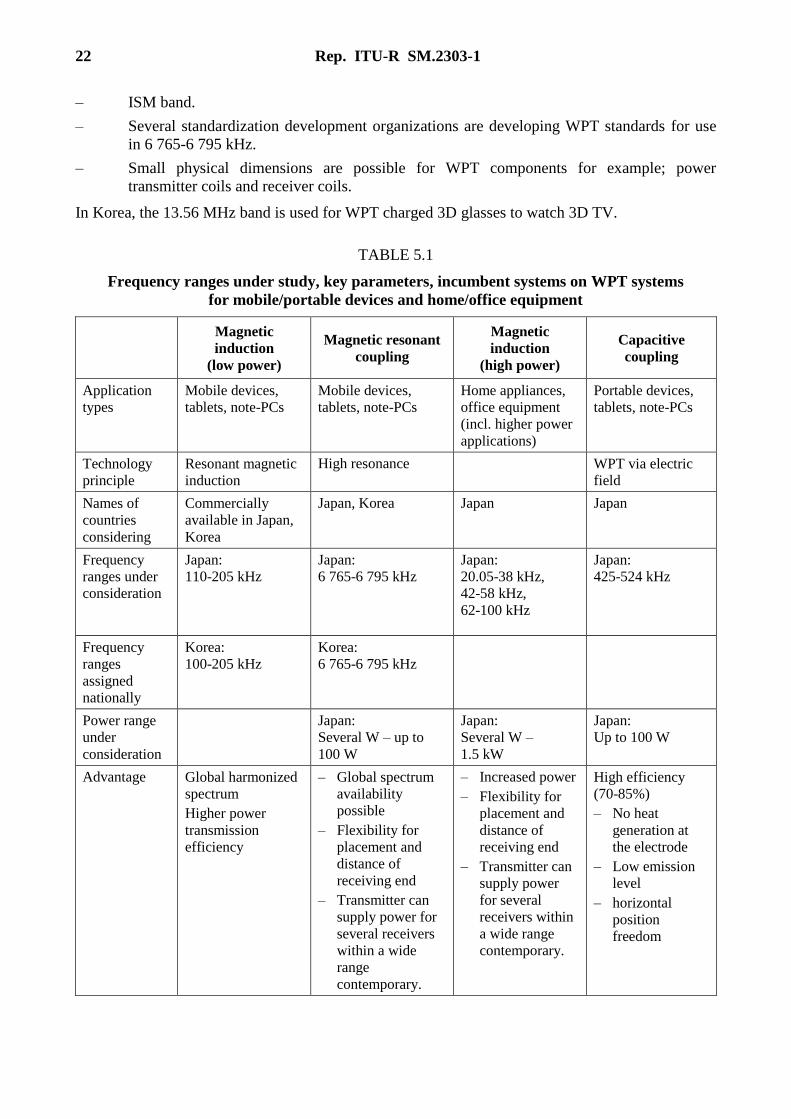
TABLE 5.1
Frequency ranges under study, key parameters, incumbent systems on WPT systems
for mobile/portable devices and home/office equipment
Magnetic
induction
(low power)
Magnetic resonant
coupling
Magnetic
induction
(high power)
Capacitive
coupling
Application
types
Mobile devices,
tablets, note-PCs
Mobile devices,
tablets, note-PCs
Home appliances,
office equipment
(incl. higher power
applications)
Portable devices,
tablets, note-PCs
Technology
principle
Resonant magnetic
induction
High resonance WPT via electric
field
Names of
countries
considering
Commercially
available in Japan,
Korea
Japan, Korea Japan Japan
Frequency
ranges under
consideration
Japan:
110-205 kHz
Japan:
6 765-6 795 kHz
Japan:
20.05-38 kHz,
42-58 kHz,
62-100 kHz
Japan:
425-524 kHz
Frequency
ranges
assigned
nationally
Korea:
100-205 kHz
Korea:
6 765-6 795 kHz
Power range
under
consideration
Japan:
Several W – up to
100 W
Japan:
Several W –
1.5 kW
Japan:
Up to 100 W
Advantage Global harmonized
spectrum
Higher power
transmission
efficiency
– Global spectrum
availability
possible
– Flexibility for
placement and
distance of
receiving end
– Transmitter can
supply power for
several receivers
within a wide
range
contemporary.
– Increased power
– Flexibility for
placement and
distance of
receiving end
– Transmitter can
supply power
for several
receivers within
a wide range
contemporary.
High efficiency
(70-85%)
– No heat
generation at
the electrode
– Low emission
level
– horizontal
position
freedom
Rep. ITU-R SM.2303-1 23
TABLE 5.1 (end)
Magnetic
induction
(low power)
Magnetic resonant
coupling
Magnetic
induction
(high power)
Capacitive
coupling
Application
Areas
Portable devices,
CE, Industrial
Fields, Specific
Areas
Portable devices,
tablets, note-PCs,
home appliances
(low power)
Home appliance
(high power), office
equipment
Portable devices,
tablets, note-PCs,
home and office
equipment
Related
Alliances/
international
standards
Wireless Power
Consortium
(WPC) [6]
A4WP [4 ]
Concerned
incumbents
for spectrum
sharing
Japan:
mobile/fixed radio
systems
Korea:
ISM band
Japan:
Standard clock
radios (40 kHz,
60 kHz)
railway radio
systems
(10-250 kHz)
Japan:
AM Broadcast
(525-1 606.5 kHz),
maritime/
NAVTEX
(405-526.5 kHz),
and amateur radio
(472-479 kHz).
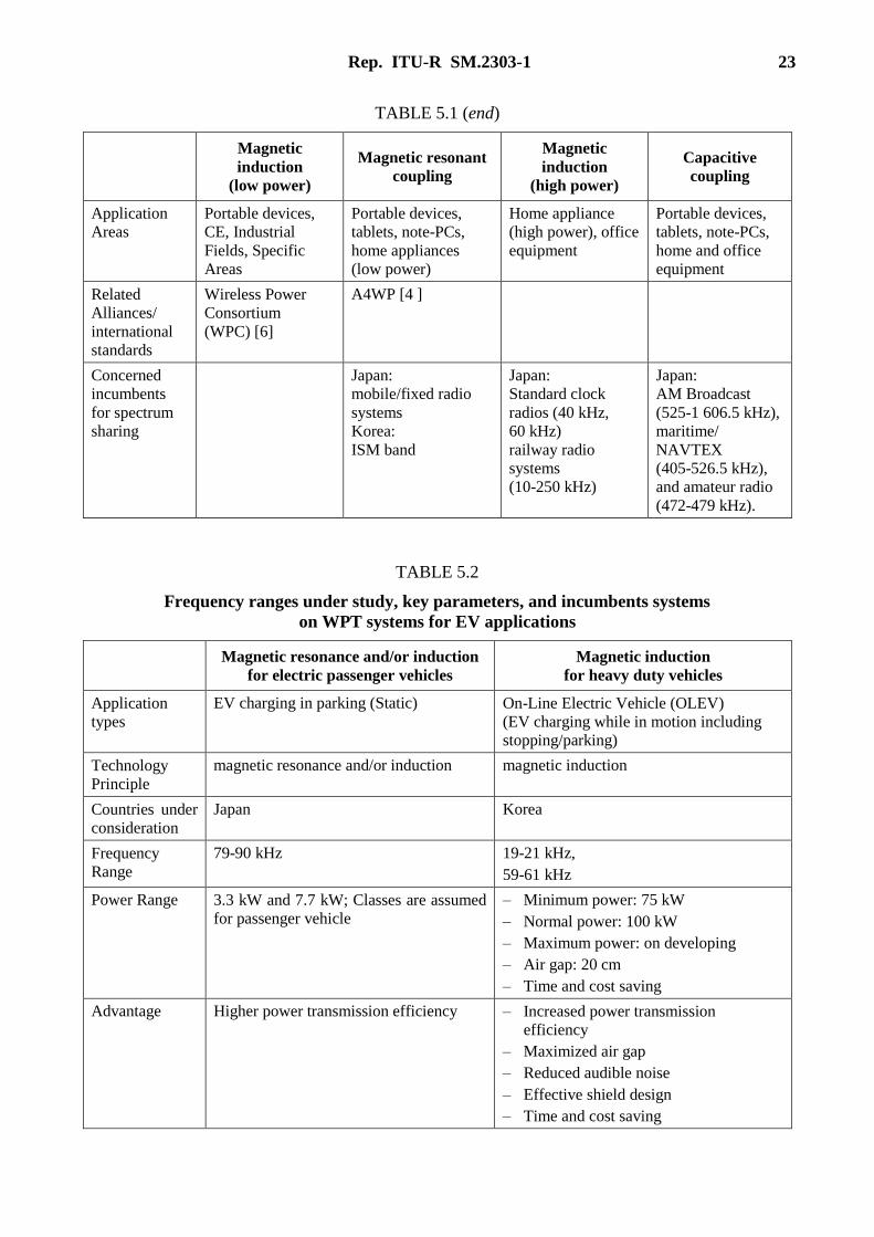
TABLE 5.2
Frequency ranges under study, key parameters, and incumbents systems
on WPT systems for EV applications
Magnetic resonance and/or induction
for electric passenger vehicles
Magnetic induction
for heavy duty vehicles
Application
types
EV charging in parking (Static) On-Line Electric Vehicle (OLEV)
(EV charging while in motion including
stopping/parking)
Technology
Principle
magnetic resonance and/or induction magnetic induction
Countries under
consideration
Japan Korea
Frequency
Range
79-90 kHz 19-21 kHz,
59-61 kHz
Power Range 3.3 kW and 7.7 kW; Classes are assumed
for passenger vehicle
– Minimum power: 75 kW
– Normal power: 100 kW
– Maximum power: on developing
– Air gap: 20 cm
– Time and cost saving
Advantage Higher power transmission efficiency – Increased power transmission
efficiency
– Maximized air gap
– Reduced audible noise
– Effective shield design
– Time and cost saving
24 Rep. ITU-R SM.2303-1
TABLE 5.2 (end)
Magnetic resonance and/or induction
for electric passenger vehicles
Magnetic induction
for heavy duty vehicles
Related
Alliance/
international
standards
IEC 61980-1 (TC69)
ISO 19363 (ISO (TC22/SC21))
SAE J2954
Concerned
incumbents for
spectrum
sharing
Standard clock radios (40 kHz, 60 kHz)
Railway radio systems (10-250 kHz)
Amateur radio (135.7-137.8 kHz)
AM broadcast (526.5-1 606.5 kHz)
Fixed maritime mobile (20.05-70 kHz) →
Ship station for radio-telegraphy
Restricted to hyperbolic curve radio-
navigation (DECCA) (84-86 kHz)
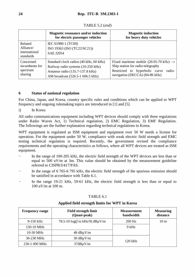
6 Status of national regulation
For China, Japan, and Korea, country specific rules and conditions which can be applied to WPT
frequency and ongoing rulemaking topics are introduced in [1] and [5].
i) In Korea
All radio communications equipment including WPT devices should comply with three regulations
under Radio Waves Act, 1) Technical regulation, 2) EMC Regulation, 3) EMF Regulation.
The followings are the further explanation regarding technical regulations in Korea.
WPT equipment is regulated as ISM equipment and equipment over 50 W needs a license for
operation. For the equipment under 50 W, compliance with weak electric field strength and EMC
testing technical regulation is required. Recently, the government revised the compliance
requirements and the operating characteristics as follows, where all WPT devices are treated as ISM
equipment.
− In the range of 100-205 kHz, the electric field strength of the WPT devices are less than or
equal to 500 uV/m at 3m. This value should be obtained by the measurement guideline
referred to CISPR/I/417/PAS.
− In the range of 6 765-6 795 kHz, the electric field strength of the spurious emission should
be satisfied in accordance with Table 6.1.
− In the range 19-21 kHz, 59-61 kHz, the electric field strength is less than or equal to
100 uV/m at 100 m.
TABLE 6.1
Applied field strength limits for WPT in Korea
Frequency range Field strength limit
(Quasi-peak)
Measurement
bandwidth
Measuring
distance
9-150 kHz 78.5-10 log(f in kHz/9) dBµV/m 200 Hz 10 m
150-10 MHz 9 kHz
10-30 MHz 48 dBµV/m
30-230 MHz 30 dBµV/m 120 kHz
230-1 000 MHz 37dBµV/m
Rep. ITU-R SM.2303-1 25
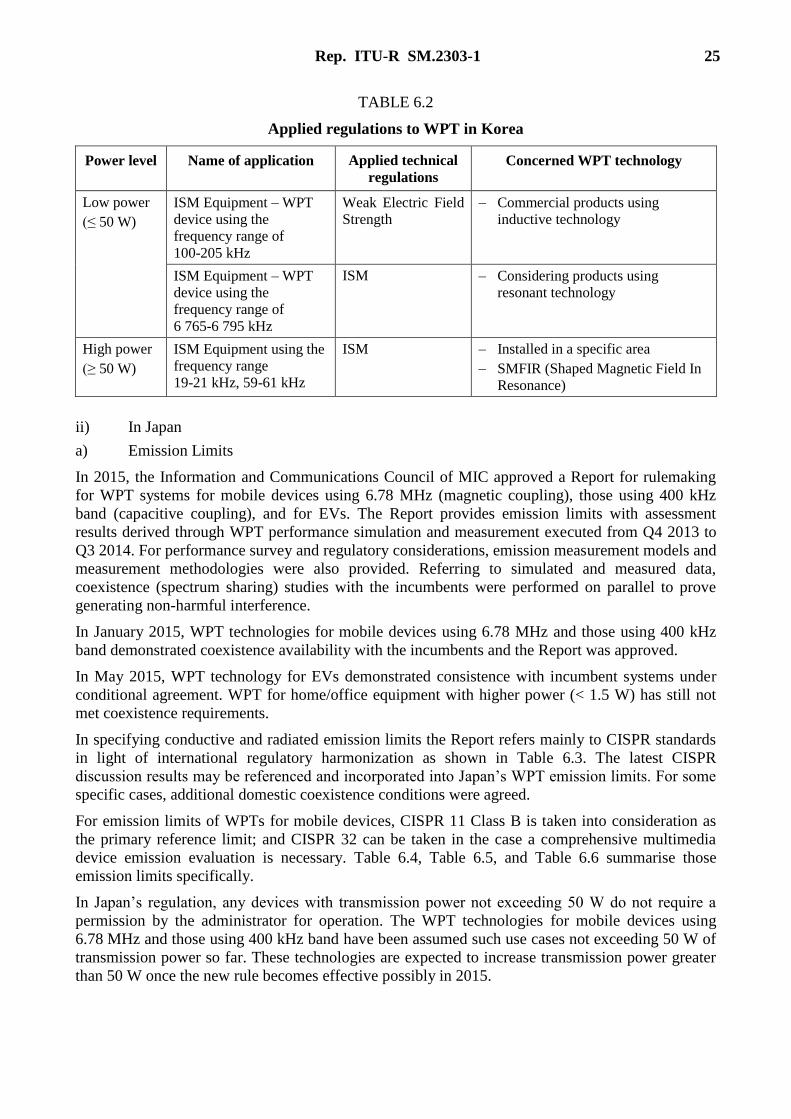
TABLE 6.2
Applied regulations to WPT in Korea
Power level Name of application Applied technical
regulations
Concerned WPT technology
Low power
(≤ 50 W)
ISM Equipment – WPT
device using the
frequency range of
100-205 kHz
Weak Electric Field
Strength
– Commercial products using
inductive technology
ISM Equipment – WPT
device using the
frequency range of
6 765-6 795 kHz
ISM – Considering products using
resonant technology
High power
(≥ 50 W)
ISM Equipment using the
frequency range
19-21 kHz, 59-61 kHz
ISM – Installed in a specific area
– SMFIR (Shaped Magnetic Field In
Resonance)
ii) In Japan
a) Emission Limits
In 2015, the Information and Communications Council of MIC approved a Report for rulemaking
for WPT systems for mobile devices using 6.78 MHz (magnetic coupling), those using 400 kHz
band (capacitive coupling), and for EVs. The Report provides emission limits with assessment
results derived through WPT performance simulation and measurement executed from Q4 2013 to
Q3 2014. For performance survey and regulatory considerations, emission measurement models and
measurement methodologies were also provided. Referring to simulated and measured data,
coexistence (spectrum sharing) studies with the incumbents were performed on parallel to prove
generating non-harmful interference.
In January 2015, WPT technologies for mobile devices using 6.78 MHz and those using 400 kHz
band demonstrated coexistence availability with the incumbents and the Report was approved.
In May 2015, WPT technology for EVs demonstrated consistence with incumbent systems under
conditional agreement. WPT for home/office equipment with higher power (< 1.5 W) has still not
met coexistence requirements.
In specifying conductive and radiated emission limits the Report refers mainly to CISPR standards
in light of international regulatory harmonization as shown in Table 6.3. The latest CISPR
discussion results may be referenced and incorporated into Japan’s WPT emission limits. For some
specific cases, additional domestic coexistence conditions were agreed.
For emission limits of WPTs for mobile devices, CISPR 11 Class B is taken into consideration as
the primary reference limit; and CISPR 32 can be taken in the case a comprehensive multimedia
device emission evaluation is necessary. Table 6.4, Table 6.5, and Table 6.6 summarise those
emission limits specifically.
In Japan’s regulation, any devices with transmission power not exceeding 50 W do not require a
permission by the administrator for operation. The WPT technologies for mobile devices using
6.78 MHz and those using 400 kHz band have been assumed such use cases not exceeding 50 W of
transmission power so far. These technologies are expected to increase transmission power greater
than 50 W once the new rule becomes effective possibly in 2015.
26 Rep. ITU-R SM.2303-1
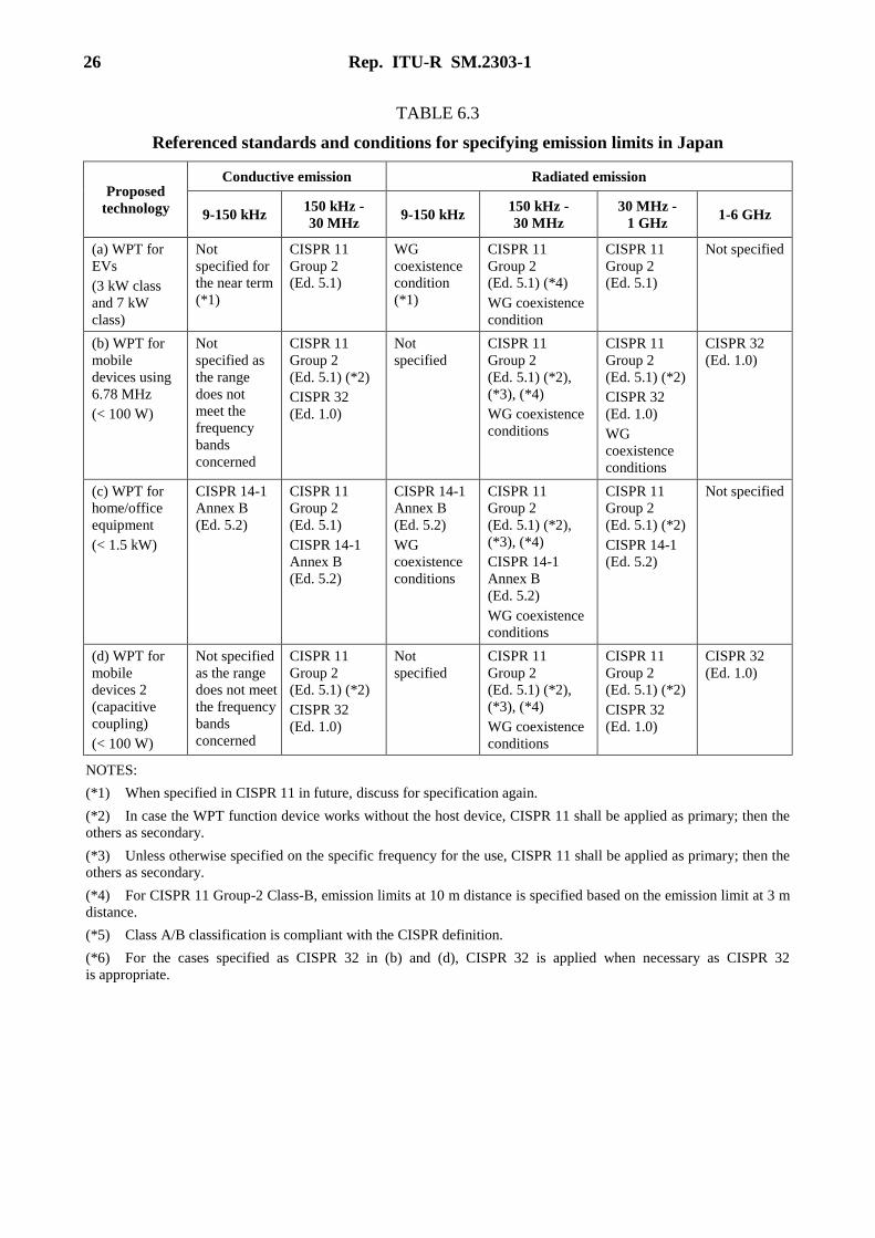
TABLE 6.3
Referenced standards and conditions for specifying emission limits in Japan
Proposed
technology
Conductive emission Radiated emission
9-150 kHz 150 kHz -
30 MHz 9-150 kHz
150 kHz -
30 MHz
30 MHz -
1 GHz 1-6 GHz
(a) WPT for
EVs
(3 kW class
and 7 kW
class)
Not
specified for
the near term
(*1)
CISPR 11
Group 2
(Ed. 5.1)
WG
coexistence
condition
(*1)
CISPR 11
Group 2
(Ed. 5.1) (*4)
WG coexistence
condition
CISPR 11
Group 2
(Ed. 5.1)
Not specified
(b) WPT for
mobile
devices using
6.78 MHz
(< 100 W)
Not
specified as
the range
does not
meet the
frequency
bands
concerned
CISPR 11
Group 2
(Ed. 5.1) (*2)
CISPR 32
(Ed. 1.0)
Not
specified
CISPR 11
Group 2
(Ed. 5.1) (*2),
(*3), (*4)
WG coexistence
conditions
CISPR 11
Group 2
(Ed. 5.1) (*2)
CISPR 32
(Ed. 1.0)
WG
coexistence
conditions
CISPR 32
(Ed. 1.0)
(c) WPT for
home/office
equipment
(< 1.5 kW)
CISPR 14-1
Annex B
(Ed. 5.2)
CISPR 11
Group 2
(Ed. 5.1)
CISPR 14-1
Annex B
(Ed. 5.2)
CISPR 14-1
Annex B
(Ed. 5.2)
WG
coexistence
conditions
CISPR 11
Group 2
(Ed. 5.1) (*2),
(*3), (*4)
CISPR 14-1
Annex B
(Ed. 5.2)
WG coexistence
conditions
CISPR 11
Group 2
(Ed. 5.1) (*2)
CISPR 14-1
(Ed. 5.2)
Not specified
(d) WPT for
mobile
devices 2
(capacitive
coupling)
(< 100 W)
Not specified
as the range
does not meet
the frequency
bands
concerned
CISPR 11
Group 2
(Ed. 5.1) (*2)
CISPR 32
(Ed. 1.0)
Not
specified
CISPR 11
Group 2
(Ed. 5.1) (*2),
(*3), (*4)
WG coexistence
conditions
CISPR 11
Group 2
(Ed. 5.1) (*2)
CISPR 32
(Ed. 1.0)
CISPR 32
(Ed. 1.0)
NOTES:
(*1) When specified in CISPR 11 in future, discuss for specification again.
(*2) In case the WPT function device works without the host device, CISPR 11 shall be applied as primary; then the
others as secondary.
(*3) Unless otherwise specified on the specific frequency for the use, CISPR 11 shall be applied as primary; then the
others as secondary.
(*4) For CISPR 11 Group-2 Class-B, emission limits at 10 m distance is specified based on the emission limit at 3 m
distance.
(*5) Class A/B classification is compliant with the CISPR definition.
(*6) For the cases specified as CISPR 32 in (b) and (d), CISPR 32 is applied when necessary as CISPR 32
is appropriate.

Rep. ITU-R SM.2303-1 27
TABLE 6.4
Emission limits for WPT mobile devices using 6.78 MHz (magnetic coupling) in Japan
WPT target
application
Conductive
emission limits
Radiated
emission
limits of
fundamental
wave
Radiated emission limits in other bands
9-150 kHz 150 kHz -
30 MHz
6.765-
6.795 MHz
9-150 kHz 150 kHz -
30 MHz
30 MHz -
1 GHz
1-6 GHz
(b) WPT
for mobile
devices
using
6.78 MHz
Not
specified
0.15-
0.50 MHz:
Quasi-peak
66-56 dBuV
(linearly
decreasing
with log(f)
Average
56-
46 dBuV
(linearly
decreasing
with log(f)
0.50-
5 MHz:
Quasi-peak
56 dBuV,
Average
46 dBuV
5-
30 MHz:
Quasi-peak
60 dBuV,
Average
50 dBuV,
except ISM
bands
6.765-
6.776 MHz:
44.0 dBuA/m
at 10 m
(quasi-peak);
6.776-
6.795 MHz:
64.0 dBuA/m
at 10 m
(quasi-peak)
Not
specified
Taking basis
on CISPR 11
Ed. 5.1,
converting to
values at 10 m
distance,
emission limit
linearly
decreases
with log(f)
from
39 dBuA/m
at 0.15 MHz
to 3 dBuA/m
at 30 MHz.
Exception-1:
20.295-
20.385 MHz:
4.0 dBuA/m
at 10 m
(quasi-peak).
Exception-2:
526.5-
1 606.5 kHz:
–2.0 dBuA/m
at 10 m
(quasi-peak)
Taking basis
on CISPR 11
Ed. 5.1, the
following is
applied:30-
80.872 MHz:
30 dBuV/m;
80.872-
81.88 MHz:
50 dBuV/m;
81.88-
134.786 MHz:
30 dBuV/m;
134.786-
136.414 MHz:
50 dBuV/m;
136.414-
230 MHz:
30 dBuV/m;
230-
1 000 MHz:
37 dBuV/m
In the case
CISPR 32
(Ed. 1.0)
should be
applied, the
limits at 3 m
in Table A.5
is applied.
Exception:
33.825-
33.975 MHz:
49.5 dBuV/m
at 10 m
(quasi-peak)
In the case
CISPR 32
(Ed. 1.0)
(1) should
be applied,
the limits
at 3 m in
Table A.5
of (1) is
applied
28 Rep. ITU-R SM.2303-1
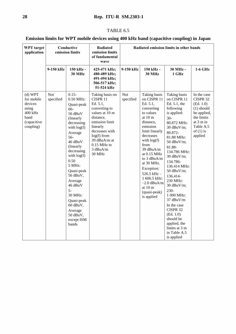
TABLE 6.5
Emission limits for WPT mobile devices using 400 kHz band (capacitive coupling) in Japan
WPT target
application
Conductive
emission limits
Radiated
emission limits
of fundamental
wave
Radiated emission limits in other bands
9-150 kHz 150 kHz -
30 MHz
425-471 kHz;
480-489 kHz;
491-494 kHz;
506-517 kHz;
51-524 kHz
9-150 kHz 150 kHz -
30 MHz
30 MHz -
1 GHz
1-6 GHz
(d) WPT
for mobile
devices
using
400 kHz
band
(capacitive
coupling)
Not
specified
0.15-
0.50 MHz:
Quasi-peak
66-
56 dBuV
(linearly
decreasing
with log(f)
Average
56-
46 dBuV
(linearly
decreasing
with log(f)
0.50
5 MHz:
Quasi-peak
56 dBuV,
Average
46 dBuV
5-
30 MHz:
Quasi-peak
60 dBuV,
Average
50 dBuV,
except ISM
bands
Taking basis on
CISPR 11
Ed. 5.1,
converting to
values at 10 m
distance,
emission limit
linearly
decreases with
log(f) from
39 dBuA/m at
0.15 MHz to
3 dBuA/m
30 MHz
Not
specified
Taking basis
on CISPR 11
Ed. 5.1,
converting
to values
at 10 m
distance,
emission
limit linearly
decreases
with log(f)
from
39 dBuA/m
at 0.15 MHz
to 3 dBuA/m
at 30 MHz.
Exception:
526.5 kHz –
1 606.5 kHz:
–2.0 dBuA/m
at 10 m
(quasi-peak)
is applied
Taking basis
on CISPR 11
Ed. 5.1, the
following
is applied:
30-
80.872 MHz:
30 dBuV/m;
80.872-
81.88 MHz:
50 dBuV/m;
81.88-
134.786 MHz:
30 dBuV/m;
134.786-
136.414 MHz:
50 dBuV/m;
136.414-
230 MHz:
30 dBuV/m;
230-
1 000 MHz:
37 dBuV/m
In the case
CISPR 32
(Ed. 1.0)
should be
applied, the
limits at 3 m
in Table A.5
is applied
In the case
CISPR 32
(Ed. 1.0)
(1) should
be applied,
the limits
at 3 m in
Table A.5
of (1) is
applied
Rep. ITU-R SM.2303-1 29
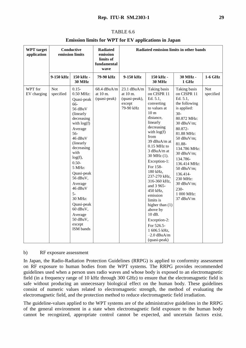
TABLE 6.6
Emission limits for WPT for EV applications in Japan
WPT target
application
Conductive
emission limits
Radiated
emission
limits of
fundamental
wave
Radiated emission limits in other bands
9-150 kHz 150 kHz -
30 MHz
79-90 kHz 9-150 kHz 150 kHz -
30 MHz
30 MHz -
1 GHz
1-6 GHz
WPT for
EV charging
Not
specified
0.15-
0.50 MHz:
Quasi-peak
66-
56 dBuV
(linearly
decreasing
with log(f)
Average
56-
46 dBuV
(linearly
decreasing
with
log(f),
0.50-
5 MHz:
Quasi-peak
56 dBuV,
Average
46 dBuV
5-
30 MHz:
Quasi-peak
60 dBuV,
Average
50 dBuV,
except
ISM bands
68.4 dBuA/m
at 10 m.
(quasi-peak)
23.1 dBuA/m
at 10 m.
(quasi-peak),
except
79-90 kHz
Taking basis
on CISPR 11
Ed. 5.1,
converting
to values at
10 m
distance,
linearly
decreasing
with log(f)
from
39 dBuA/m at
0.15 MHz to
3 dBuA/m at
30 MHz (1).
Exception-1:
For 158-
180 kHz,
237-270 kHz,
316-360 kHz,
and 3 965-
450 kHz,
emission
limits is
higher than (1)
above by
10 dB.
Exception-2:
For 526.5-
1 606.5 kHz,
–2.0 dBuA/m
(quasi-peak)
Taking basis
on CISPR 11
Ed. 5.1,
the following
is applied:
30-
80.872 MHz:
30 dBuV/m;
80.872-
81.88 MHz:
50 dBuV/m;
81.88-
134.786 MHz:
30 dBuV/m;
134.786-
136.414 MHz:
50 dBuV/m;
136.414-
230 MHz:
30 dBuV/m;
230-
1 000 MHz:
37 dBuV/m
Not
specified
b) RF exposure assessment
In Japan, the Radio-Radiation Protection Guidelines (RRPG) is applied to conformity assessment
on RF exposure to human bodies from the WPT systems. The RRPG provides recommended
guidelines used when a person uses radio waves and whose body is exposed to an electromagnetic
field (in a frequency range of 10 kHz through 300 GHz) to ensure that the electromagnetic field is
safe without producing an unnecessary biological effect on the human body. These guidelines
consist of numeric values related to electromagnetic strength, the method of evaluating the
electromagnetic field, and the protection method to reduce electromagnetic field irradiation.
The guideline-values applied to the WPT systems are of the administrative guidelines in the RRPG
of the general environment in a state when electromagnetic field exposure to the human body
cannot be recognized, appropriate control cannot be expected, and uncertain factors exist.
30 Rep. ITU-R SM.2303-1
For example, the state where residents are exposed to the electromagnetic field in general
residential environment falls under this case.
However, in the case a human body is located within 20 cm from the WPT system operating in the
frequency range of 10 kHz to 100 kHz, for which the partial body absorption guidelines cannot be
applied, the basic guidelines in the RRPG is applied.
The basic guidelines do not discriminate the general environment and the professional environment;
therefore, in case of applying the general guidelines, the values counting safety factor of 1/5
(1/√5 in electromagnetic field strength and electric current density) which is applied in the
administrative guidelines.
Assessment methodology provides the assessment Patterns to perform conformity assessment to the
RRPG which provides the guideline values and the guidelines. An assessment Pattern is defined by
the combination of the following parameters. Each target WPT technology (e.g. WPT using
6.78 MHz WPT for mobile, WPT for EVs) has independent assessment Patterns.
1) Possibility of human body located < 20 cm from the WPT system or located between
the transmitting and receiving coils.
2) Contact hazard protection.
3) Ungrounded condition,
4) Whole body average SAR.
5) Partial body SAR.
6) Induced current density.
7) Contact current.
8) Outer electric field, and
9) Outer magnetic field.
The simplest assessment Pattern of all the target WPT technologies consists of 8) and 9) above,
which is the minimum number combination of the parameters. In the evaluation, this simplest
pattern is assumed to derive the worst (maximum) radio wave energy absorption to the human body.
In other words, much larger excess RF exposure than actual exposure value to the human body is
estimated; and then the assessment would result in much lower allowable emission power from the
WPT system.
The other Patterns consist of more number of the parameters. As the number of the adopted
parameters increases, assessment methodology requires more detailed evaluation, which results in
more accurate RF exposure estimation. Some patterns prepared for detailed assessment apply a
coupling factor which is multiplied with the measured maximum magnetic field strength to confirm
that RF exposure is less than the guideline values. Derivation of a coupling factor is also provided.
If one demonstrated conformity of a system using one of the target WPT technologies to the
guideline values is defined in any one of the patterns, the system is deemed conforming to the
RRPG.
If a new assessment methodology which is intended for an assessment is qualified by appropriate
engineering approaches in the future or it can prove an improvement in the applicable assessment
methodologies as appropriate, it can be applied for this purpose.
Noting at the end of this section, for the RRPG, ICNIRP 2010 guideline has been agreed for
adoption for low frequency ranges. Hence, human exposure should be qualified for exposure
quantities to prevent nerve stimulation in addition to prevent tissue heating on SAR for in 100 kHz
to 10 MHz frequency range.
Rep. ITU-R SM.2303-1 31
iii) In China
This section provides classification and regulation analysis on WPT device in current Chinese radio
regulation system with regard to WPT device and WPT wireless communication part according to
the definition, frequency range and restriction of different radio devices.
a) Classification and regulation analysis on WPT device
China does not have official WPT regulations. Currently, only the SRD regulation covers all the
WPT frequency bands. Therefore, in order to protect the incumbent radio communication systems,
WPT device has to go through a market entrance test which is the same as SRD market entrance
test. However, it is not appropriate to regulate WPT devices as SRD in the long term. Hence, the
classification and regulation research of WPT is done as follows. As the research is in the early
phase, different regulation and classification methods are not excluded.
a-1) ISM device
a-1-1) Analysis from frequency range and definition perspectives
In Chinese radio regulation system, ISM device is defined as: the equipment or apparatus using RF
energy for industrial, scientific, medical, household and similar purpose, which does not include the
equipment used in telecommunication, information technology and other national standards. WPT
device is the equipment used in household or industrial field to using RF energy. Therefore, WPT
device can be put under ISM device.
According to Chinese ISM regulations[10], ISM devices are divided into two groups based on their
applications: (1) all the ISM devices which produce and/or use conductively coupled RF energy
intentionally for playing its own function; (2) all the ISM devices, including EDM and arc welding
equipment, which produce or use electromagnetic RF energy intentionally to treat material.
In addition, each group is divided into two categories according to their application scenarios:
(A) the ISM devices which are not used in house or are not directly connected to residential
low-voltage power facilities; (B) the ISM devices which are used in house or are directly connected
to residential low-voltage power facilities.
According to Chinese ISM regulations[10], which is equivalent to CISPR 11:2003, whether the WPT
frequency range, 6.675-6.795 MHz, belongs to the scope of ISM frequency range or not needs a
special permission from Chinese radio regulatory agency. Nevertheless, the other WPT frequency
ranges do not belong to the scope of ISM frequency range.
Hence, based on the analysis above, if the permission is available, the WPT device working in
6.675-6.795 MHz band belongs to the B category of group 2 ISM device.
a-1-2) Analysis from restriction perspective
According to Chinese ISM regulations [10], the in band transmission power restriction of ISM device
working in 6.675MHz-6.795MHz band is under consideration. Furthermore, its spurious radiation
needs to satisfy the electromagnetic radiation disturbance restriction shown in Table 6.7.

32 Rep. ITU-R SM.2303-1
TABLE 6.7
The electromagnetic radiation disturbance restriction
of the B category of group 2 ISM device
Frequency range/MHz Disturbance restriction of the B category of the group
2 ISM device/dB(μV/m) (measured at 10 m)
0.15-30 –
30-80.872 30
80.872-81.848 50
81.848-134.768 30
134.768-136.414 50
136.414-230 30
230-1 000 37
(China’s ISM standard, GB 4824-2004, is equivalent to CISPR 11:2003. Group 1 is for ISM equipment that generated
and/or used conductively coupled radio-frequency energy. Group 2 is ISM equipment in which radio-frequency energy
is intentionally generated and/or used in the form of electromagnetic radiation)
Based on the analysis above, if the permission is available, the WPT devices working in
6.675-6.795 MHz band can be administered in accordance with the B category of group 2 ISM
device in China. Moreover, the WPT working in other frequency bands cannot be administered in
accordance with ISM equipment according to current Chinese radio regulation.
a-2) Short Range Device (SRD)
a-2-1) Analysis from frequency range and definition perspectives
In Chinese radio regulation system[11], SRD has 7 categories from the A category to the G category.
Among them, the working frequency bands of the categories from A to D are below 30 MHz.
The frequency band of the A category is 9-190 kHz. The frequency bands of the B category and
WPT working frequency bands do not overlap. The frequency bands of the C category include
6.675-6.795 MHz. The D category, whose working frequency band is 315 kHz - 30 MHz, includes
all the SRD except the A category, the B category and the C category. Hence, all the WPT working
frequency bands except 190-205 kHz band belong to the frequency range of SRD. Furthermore, the
frequency band of the first generation WPC’s WPT device is partial beyond the scope of the
category A SRD’s frequency band. Therefore, in frequency standpoint, all the WPT devices are in
the scope of SRD except the WPT device working in 190-205 kHz band.
There is no definition of SRD in existing Chinese radio regulation system. Nonetheless, the existing
administration regulation[11] was established for general micro-power (short range) radio
transmitting equipment. The power transfer of WPT device does not belong to the category of radio
emission. The vast majority of power is transmitted to receiver through coupling, induction and
other technologies, rather than radiating energy to the wireless space. Therefore, in definition
perspective, WPT device does not belong to the scope of SRD.
In terms of the impact of wireless signal on environment, WPT device can be administrated
temporally in accordance with SRD regulation method. This administration method can make sure
that the impact of WPT device on wireless environment does not exceed the impact of SRD in
corresponding frequency band. But in the long term, it is not suitable to administrate WPT device in
accordance with SRD.

Rep. ITU-R SM.2303-1 33
a-2-2) Analysis from restriction perspective
According to the regulation[6], SRD only has to satisfy the magnetic field strength limit.
The magnetic field strength limit of the category A SRD, the category C SRD and the category D
SRD are shown in Table 6.8.
TABLE 6.8
The magnetic field strength limit of the category A SRD,
the category C SRD and the category D SRD
Category Corresponding frequency band
of WPT devices
Magnetic field strength restriction
(10 m)
The category A SRD 9-190 kHz
The frequency band of the first
generation WPC’s WPT device is
partial beyond the scope of the
category A SRD’s frequency band
72 dBμA/m
The category C SRD 6 765-6 795 kHz 42 dBμA /m
The category D SRD 425-524 kHz –5 dBμA /m
a-3) The result of analysis on WPT device classification and administration regulation
In conclusion, if the permission is available, the WPT devices working in 6.675-6.795 MHz band
can be administered in accordance with the B category of group 2 ISM device, and the WPT
devices working in other band can be administered in accordance with SRD temporally. In the long
term, it is necessary to allocate WPT frequency band as soon as possible and formulate the EMC
technical specifications of WPT device.
b) Analysis on wireless communication part of WPT device
Before power transfer, in order to make sure the secondary WPT device exist, the primary WPT
device needs to realize the handshake process through wireless communication.
This communication process has short range, short time and micro power characteristics, which are
in accordance with the characteristic of SRD communication. Hence, if the working frequency band
of the wireless communication part of WPT device is in the scope of SRD, it is regulated as SRD.
7 Status of co-existence studies between WPT and radiocommunication services,
including the radio astronomy service
In light of the high field strengths that can be produced by WPT systems, there is the potential for
interference to communications signals operating in nearby bands. A determination of the required
characteristics of WPT RF signals must be based on studies of potential interference from WPT to
other services. Such studies and the resultant determination of characteristics must be completed
prior to the assignment of frequencies for WPT.
Figures 7.1 and 7.2 show the WPT spectrum under considerations in Japan and assigned in
Korea [1]. Spectrum sharing studies should be performed between the concerned systems with WPT
systems to clarify the availability of coexistence. Some WPT equipment are classified into ISM
equipment which shall not cause harmful nor claim protection from other stations.
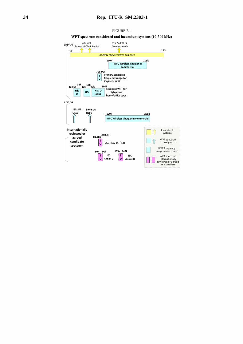
34 Rep. ITU-R SM.2303-1
FIGURE 7.1
WPT spectrum considered and incumbent systems (10-300 kHz)
40k, 60k: Standard Clock Radios
Railway radio systems and misc
10k 250k
135.7k-137.8k: Amateur radio
EV
JAPAN
KOREA
H&O
HOH & O apps
100k
79k 90k
42k 58k
20.05k38k
62kResonant WPT for
high power home/office apps
Primary candidate frequency range for EV/PHEV WPT
59k-61k: OLEV
Internationally reviewed or
agreed candidate spectrum
WPC Wireless Charger in commercial
110k 205k
WPC Wireless Charger in commercial
100k 205k
EV
81.38k90.00k
SAE (Nov 14, ’13)
19k-21k: OLEV
EV
80k 90k
IEC Annex C
EV
135k 145k
IEC Annex B
Incumbent systems
WPT spectrum assigned
WPT frequency ranges under study
WPT spectrum internationally
reviewed or agreed as a candiate
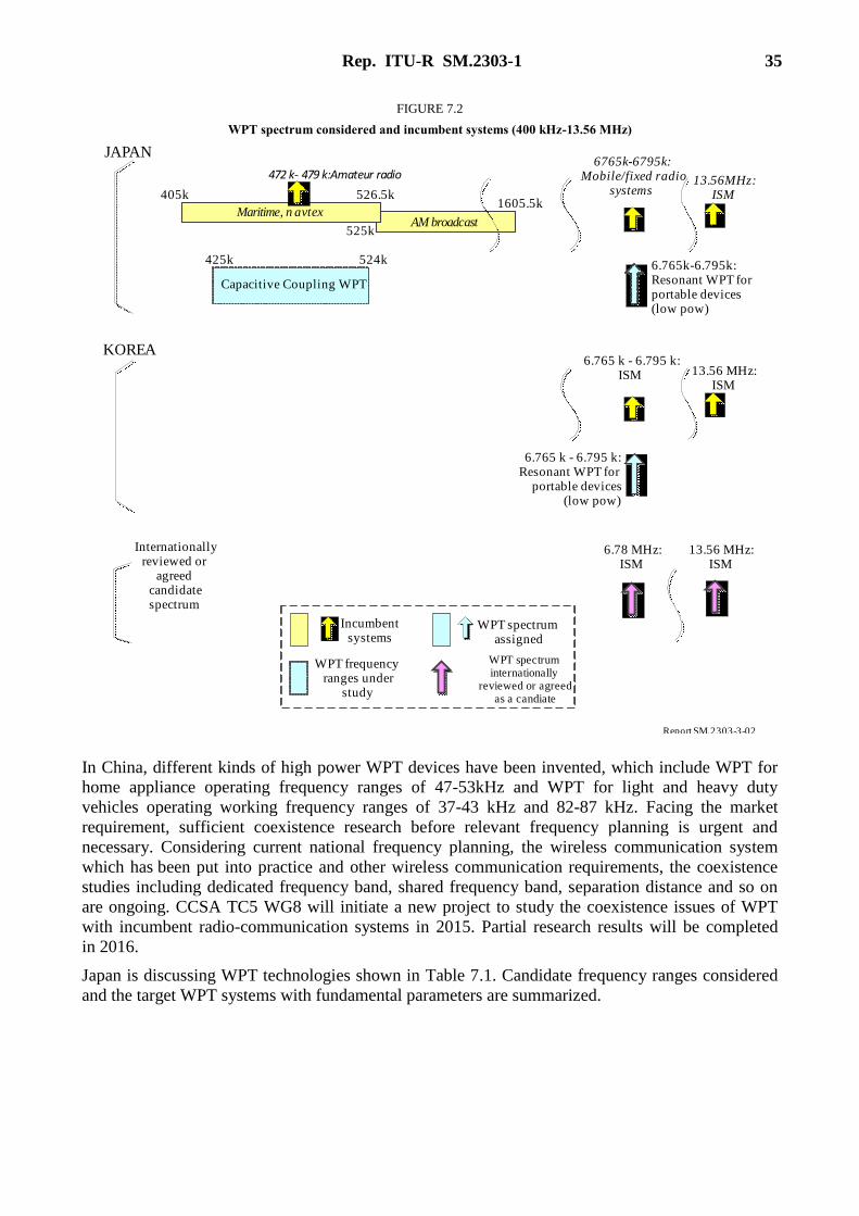
Rep. ITU-R SM.2303-1 35
FIGURE 7.2
WPT spectrum considered and incumbent systems (400 kHz-13.56 MHz)
R pe ort SM.2303-3-02
AM broadcast525k
1605.5kMaritime, n avtex
405k 526.5k
472 k- 479 k:Amateur radio6765k-6795k:
Mobile/fixed radiosystems
6.765k-6.795k:Resonant WPT forportable devices(low pow)
13.56MHz:ISM
Capacitive Coupling WPT
524k425k
JAPAN
KOREA
Internationallyreviewed or
agreedcandidatespectrum
Incumbentsystems
WPT frequencyranges under
study
WPT spectrumassigned
WPT spectruminternationally
reviewed or agreedas a candiate
6.765 k - 6.795 k:Resonant WPT for
portable devices(low pow)
6.765 k - 6.795 k:ISM 13.56 MHz:
ISM
13.56 MHz:ISM
6.78 MHz:ISM
In China, different kinds of high power WPT devices have been invented, which include WPT for
home appliance operating frequency ranges of 47-53kHz and WPT for light and heavy duty
vehicles operating working frequency ranges of 37-43 kHz and 82-87 kHz. Facing the market
requirement, sufficient coexistence research before relevant frequency planning is urgent and
necessary. Considering current national frequency planning, the wireless communication system
which has been put into practice and other wireless communication requirements, the coexistence
studies including dedicated frequency band, shared frequency band, separation distance and so on
are ongoing. CCSA TC5 WG8 will initiate a new project to study the coexistence issues of WPT
with incumbent radio-communication systems in 2015. Partial research results will be completed
in 2016.
Japan is discussing WPT technologies shown in Table 7.1. Candidate frequency ranges considered
and the target WPT systems with fundamental parameters are summarized.

36 Rep. ITU-R SM.2303-1
TABLE 7.1
WPT technologies considered in Japan MIC WPT Working Group discussion
Target WPT
applications (a) WPT for EVs
(b) WPT for
mobile and
portable devices
(1)
(c) WPT for home
appliances and
office equipment
(d) WPT for
mobile and
portable devices
(2)
WPT
technology
Magnetic field power transmission (inductive, resonance) Capacitive
coupling
Transmission
power
Up to approx.3 kW
(max 7.7 kW)
Several W –
approx.100 W
Several W-1.5 kW Approx.100 W
Candidate
WPT
frequency
ranges
42-48 kHz
(45 kHz band),
52-58 kHz
(55 kHz band),
79-90 kHz
(85 kHz band),
140.91-148.5 kHz
(145 kHz band)
6 765-6 795 kHz 20.05-38 kHz,
42-58 kHz,
62-100 kHz
425-524 kHz
Transmission
distance
0 – approx. 30 cm 0 – approx. 30 cm 0 – approx. 10 cm 0 – approx. 1 cm
The information in this Table may be changed by the domestic and global standardization trend of WPT.
Japan
For spectrum sharing and coexistence studies, the WPT-Working Group (WG) under MIC’s
Committee on Electromagnetic Environment for Radio-wave Utilization picked up many possible
and practical combinations of the incumbent radio systems and the target WPT systems which
might cause a harmful interference event in specific use cases. In such an event, the fundamental
WPT radio wave may fall in the same spectrum of the incumbent radio systems when located within
the minimum required separation distance from the WPT device or when an appropriate power
attenuation measure is not taken. In another case, a WPT harmonic wave might fall into the
spectrum of the incumbent radio system to cause degradation of signal quality at the incumbent
radio receiver. There must be so many varieties of the events. The WG defined the worst case
conditions to assess coexistence. Usage scenarios have been reviewed; and then, simulations and
field experiments have been performed. The coexistence conditions, which gives a criteria of the
use of a WPT system, were defined by the WG based on the current unacceptable harmful emission
limits to the incumbent system and actual use cases assumed.
In December 2014, 6.78 MHz magnetic coupling WPT and capacitive coupling WPT demonstrated
coexistence in the defined conditions.
6.78 MHz magnetic coupling WPT device coexistence with the public radio systems using small
frequency segments in the range of 6.765-6.795 MHz were assessed. The maximum transmission
power of 100 W was assumed. Specific emission limits (see Table 6.4) were derived and specified
per a small segment in the range to meet coexistence requirements.
Rep. ITU-R SM.2303-1 37
Capacitive coupling WPT device coexistence was assessed by theoretical calculation and field
experiments. The results showed much lower magnetic emission strength than the emission limit
requirement to coexist with the concerned incumbents. Accordingly, coexistence of a capacitive
coupling WPT device with transmission power less than 100 W was proved. It should be noted that,
however, frequency ranges used for maritime radio devices and amateur radio devices were
excluded from the candidate operation frequency ranges as international spectrum usage is taken
into consideration.
Another magnetic coupling WPT technology using kHz range for home appliance has still not
demonstrated coexistence for all the defined test cases in the assessment.
WPT for EV applications using 79-90 kHz demonstrated coexistence with standard clock radio
devices, AM broadcast devices, and Amateur radios. Those using the other candidate frequency
ranges than 79-90 kHz have still not met with the requirements. Thus, candidate frequency ranges
for EV have converged to the 79-90 kHz range.
The WG performed further assessment to prove coexistence with railway wireless systems, namely
Automatic Train Stop Systems (ATS) deployed all over the railway networks in Japan and
Inductive Train Radio Systems (ITRS) for very specific actual use cases. The WG finally agreed on
the technical requirements on coexistence with railway wireless systems.
As a result of coexistence studies, Japan would like to add emphasis to global attention to
coexistence study with railway wireless systems in particular ATS. Today, ATS is operated around
100 kHz and is deployed not only in the Japanese railway network but also in many countries and
regional railway networks of the globe. In the future, it may happen that many countries deploying
ATS face the same issue to prove coexistence with WPT systems to ensure the safety of the
passengers. This study should be taken into global consideration, not in a country specific approach.
Japan believes that ITU-R is invited to take action on this study in collaboration with CISPR.
Railway wireless systems by electro-magnetic control mechanism are absolutely crucial for secure
operation. Robustness of the systems against unwanted radio waves is a critical measure and may
have independent characteristics from one by one. Accordingly, coexistence criteria for the systems
differs from one country or one region to another. Therefore, emission limits to specify in CISPR
should take account of such variety and reliability of the systems.
Table 7.2 (A), (B), (C) and Table 7.3 summarize results of coexistence studies and ongoing
considerations.

38 Rep. ITU-R SM.2303-1
TABLE 7.2
Summary of WPT for mobile and home appliance coexistence study results
and ongoing considerations in Japan
(A) Coexistence with Standard Clock Radio Devices, Automatic Train Stop Systems, and
Inductive Train Radio Systems
WPT for mobile and
home appliances
Incumbent systems
Technologies Candidate
frequency
ranges
Standard Clock
Radio Devices
(SCRD) (*1)
(40 kHz, 60 kHz)
ATS (*2)
(10-250 kHz)
ITRS (*3)
(10-250 kHz)
Magnetic
coupling
(low power for
mobile devices)
6,765-
6,795 kHz
N/A N/A N/A
Magnetic
coupling
(low-high
power for home
appliances)
20.05-38 kHz Meets coexistence
conditions with the
notes below:
• The 2nd and 3rd
harmonics shall not
fall in the SCRD
operation bands.
• Inviting users’
attention to the
possibility of
interference to the
SCRD devices
Further assessment
necessary for
coexistence.
• Need to derive
required separation
distance not to cause
harmful interference
Meets coexistence
conditions
42-58 kHz Meets coexistence
conditions
62-100 kHz Further assessment
necessary.
• Need to derive required
separation distance not
to cause harmful
interference
Capacitive
Coupling
(low power for
mobile devices)
425-524 kHz N/A Meets coexistence
conditions by reducing
magnetic field strength
by 12 dB achieved
N/A
Coexistence conditions in assessment:
(*1) Standard clock radio devices: WPT devices shall not cause harmful interference in
simulated use cases.
• Separation distance of 10 m was used as a coexistence criterion. In addition to the
fundamental wave characteristics, integer harmonics was examined as well when
they fall into the Standard clock radios operation bands.
• Additional measure on operation time condition is considered since WPT operation
of home/office equipment is not expected or observed less frequently in midnight
when Standard clock radios receive their signals frequently. Advertisement of radio
hazard from WPT for home appliances may lead to less interference to share the
same spectrum as utilization time is not overlapped entirely.
• WPT harmonics generated fundamental waves of 20.05 kHz and 30 kHz fall into the
Standard clock radios operation spectrum. This is critical to ensure non-harmful
interference.
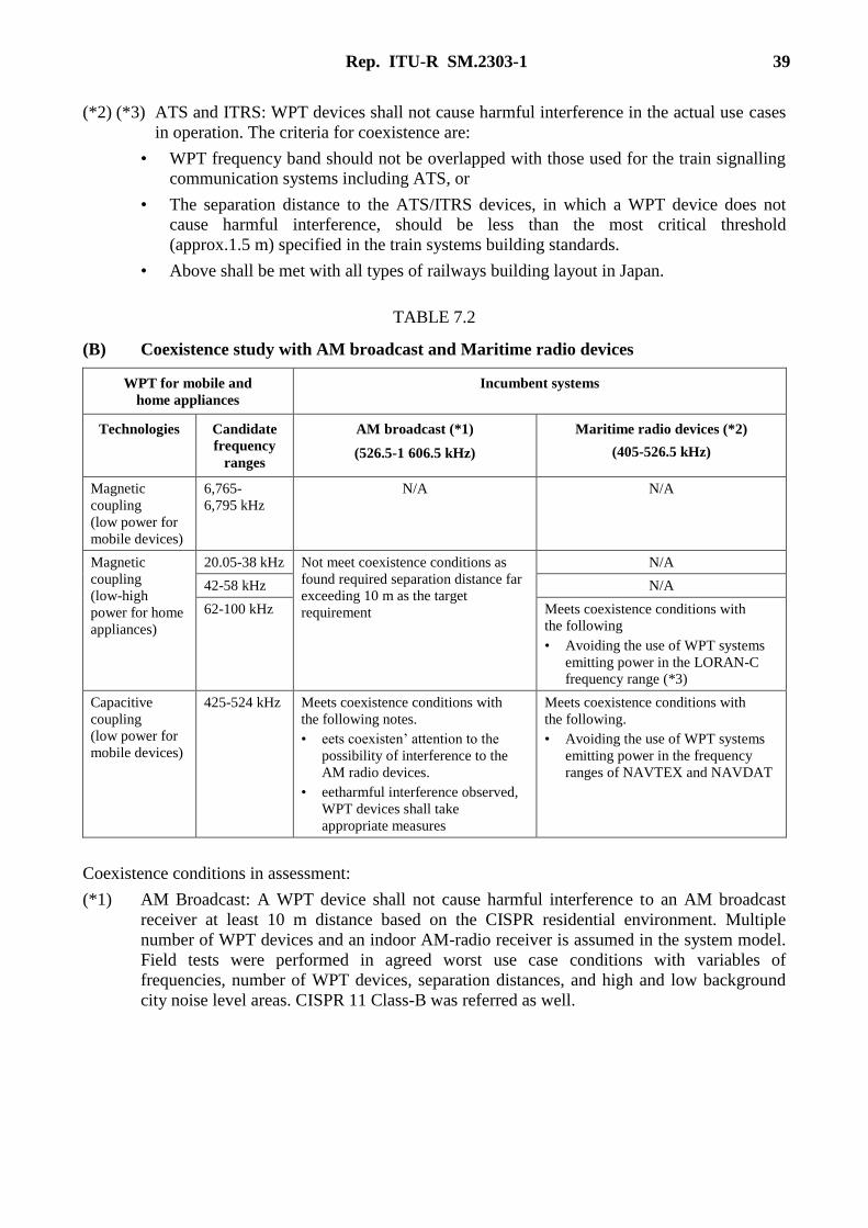
Rep. ITU-R SM.2303-1 39
(*2) (*3) ATS and ITRS: WPT devices shall not cause harmful interference in the actual use cases
in operation. The criteria for coexistence are:
• WPT frequency band should not be overlapped with those used for the train signalling
communication systems including ATS, or
• The separation distance to the ATS/ITRS devices, in which a WPT device does not
cause harmful interference, should be less than the most critical threshold
(approx.1.5 m) specified in the train systems building standards.
• Above shall be met with all types of railways building layout in Japan.
TABLE 7.2
(B) Coexistence study with AM broadcast and Maritime radio devices
WPT for mobile and
home appliances
Incumbent systems
Technologies Candidate
frequency
ranges
AM broadcast (*1)
(526.5-1 606.5 kHz)
Maritime radio devices (*2)
(405-526.5 kHz)
Magnetic
coupling
(low power for
mobile devices)
6,765-
6,795 kHz
N/A N/A
Magnetic
coupling
(low-high
power for home
appliances)
20.05-38 kHz Not meet coexistence conditions as
found required separation distance far
exceeding 10 m as the target
requirement
N/A
42-58 kHz N/A
62-100 kHz Meets coexistence conditions with
the following
• Avoiding the use of WPT systems
emitting power in the LORAN-C
frequency range (*3)
Capacitive
coupling
(low power for
mobile devices)
425-524 kHz Meets coexistence conditions with
the following notes.
• eets coexisten’ attention to the
possibility of interference to the
AM radio devices.
• eetharmful interference observed,
WPT devices shall take
appropriate measures
Meets coexistence conditions with
the following.
• Avoiding the use of WPT systems
emitting power in the frequency
ranges of NAVTEX and NAVDAT
Coexistence conditions in assessment:
(*1) AM Broadcast: A WPT device shall not cause harmful interference to an AM broadcast
receiver at least 10 m distance based on the CISPR residential environment. Multiple
number of WPT devices and an indoor AM-radio receiver is assumed in the system model.
Field tests were performed in agreed worst use case conditions with variables of
frequencies, number of WPT devices, separation distances, and high and low background
city noise level areas. CISPR 11 Class-B was referred as well.

40 Rep. ITU-R SM.2303-1
(*2) Maritime radio devices: A WPT device shall not cause harmful interference. Assessment
showed that the proposed WPT system has possibility substantially to coexist with the
maritime radio systems. However, it is worth noting that the following frequencies in the
frequency range in this study are used for secure marine navigation safety. Therefore, the
same frequencies have been deleted for the use. (i) NAVTEX: 518 kHz (424 kHz, 490 kHz)
(ii) NAVDAT: 495-505 kHz. In addition, harmonics should not fall into the Marine VHF
radio band (156-162 MHz) used internationally.
(*3) LORAN-C, eLORAN (90-100 kHz): Maritime radiocommunication operators commented
that this spectrum should not be arranged for the use of WPT.
TABLE 7.2
(C) Coexistence Amateur radio devices and Public radio systems
WPT for mobile and home appliances Incumbent systems
Technologies Candidate
frequency
ranges
Amateur radio devices (*1)
(135.7-137.8 kHz, 472-479 kHz)
Public radio systems (*2)
(6,765-6,795 kHz)
Magnetic coupling
(low power for
mobile devices)
6,765-6,795 kHz Meets coexistence conditions with
the following
• Avoiding the use of WPT
systems transmitting power in
the amateur radio frequency
ranges
Meets coexistence conditions
with specific emission limits
provided
Magnetic coupling
(low-high power for
home appliances)
20.05-38 kHz NA
42-58 kHz NA
62-100 kHz NA
Capacitive coupling
(low power for
mobile devices)
425-524 kHz NA
Coexistence conditions in assessment:
(*1) Amateur radio devices: For capacitive coupling, 472-479 kHz band is an in-band case
(sharing the same spectrum). For Amateur Radios, no official interference level
requirements or rules from other systems are found. However, an agreement was to exclude
this band allocated to Amateur Radios in the WPT operation frequency range and to set
appropriate frequency offset.
(*2) Public radio systems: 6 765-6 795 kHz is not designated as an ISM band in Japan.
However, the regulations’ provisions allow the use for WPT applications in the band. New
emission limits for WPT products in this band have been agreed, which may allow
coexistence with the incumbent systems and higher transmission power in this band.
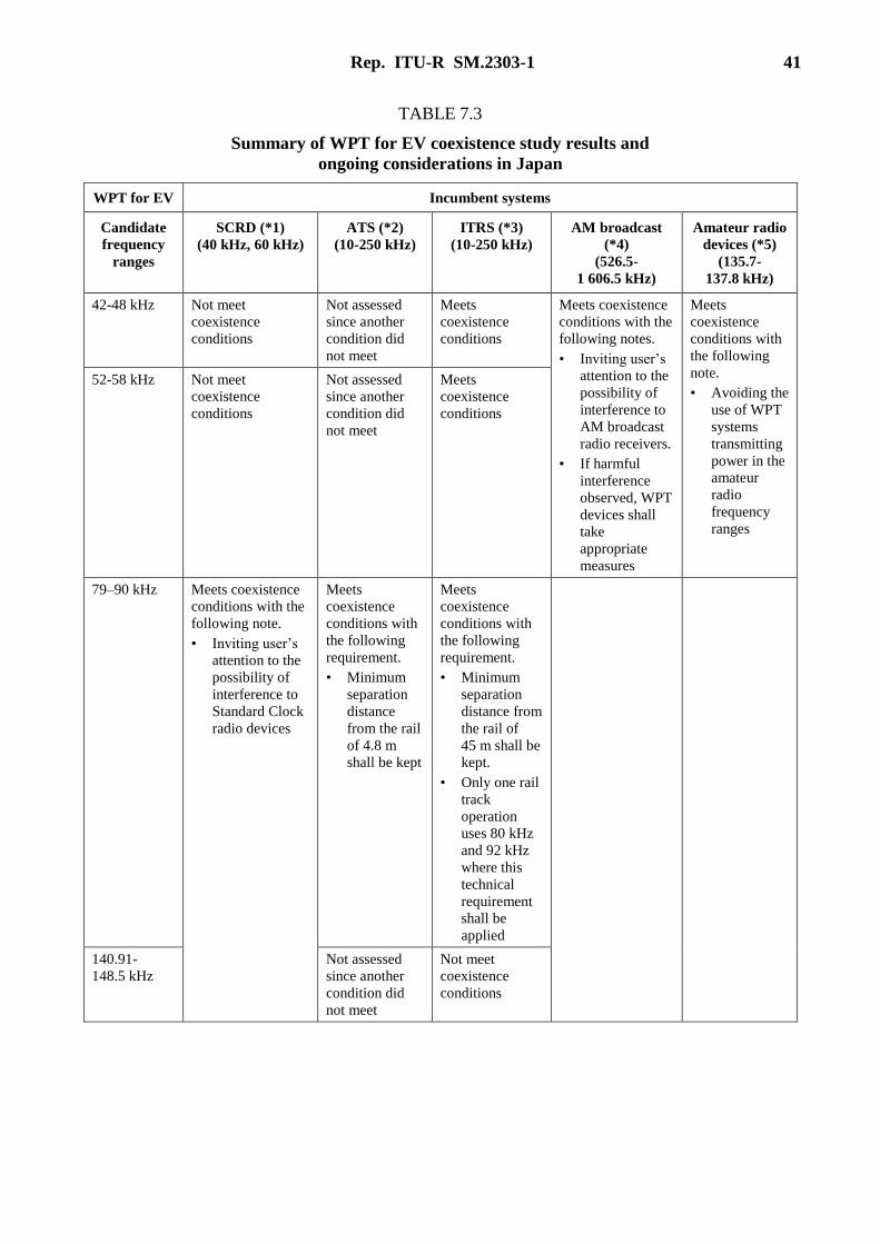
Rep. ITU-R SM.2303-1 41
TABLE 7.3
Summary of WPT for EV coexistence study results and
ongoing considerations in Japan
WPT for EV Incumbent systems
Candidate
frequency
ranges
SCRD (*1)
(40 kHz, 60 kHz)
ATS (*2)
(10-250 kHz)
ITRS (*3)
(10-250 kHz)
AM broadcast
(*4)
(526.5-
1 606.5 kHz)
Amateur radio
devices (*5)
(135.7-
137.8 kHz)
42-48 kHz Not meet
coexistence
conditions
Not assessed
since another
condition did
not meet
Meets
coexistence
conditions
Meets coexistence
conditions with the
following notes.
• Inviting user’s
attention to the
possibility of
interference to
AM broadcast
radio receivers.
• If harmful
interference
observed, WPT
devices shall
take
appropriate
measures
Meets
coexistence
conditions with
the following
note.
• Avoiding the
use of WPT
systems
transmitting
power in the
amateur
radio
frequency
ranges
52-58 kHz Not meet
coexistence
conditions
Not assessed
since another
condition did
not meet
Meets
coexistence
conditions
79–90 kHz Meets coexistence
conditions with the
following note.
• Inviting user’s
attention to the
possibility of
interference to
Standard Clock
radio devices
Meets
coexistence
conditions with
the following
requirement.
• Minimum
separation
distance
from the rail
of 4.8 m
shall be kept
Meets
coexistence
conditions with
the following
requirement.
• Minimum
separation
distance from
the rail of
45 m shall be
kept.
• Only one rail
track
operation
uses 80 kHz
and 92 kHz
where this
technical
requirement
shall be
applied
140.91-
148.5 kHz
Not assessed
since another
condition did
not meet
Not meet
coexistence
conditions

42 Rep. ITU-R SM.2303-1
Coexistence conditions in assessment
(*1) Standard clock radio devices: WPT devices shall not cause harmful interference defined
by C/I ratio derived from the minimum receiver sensitivity of the Standard clock radio
devices in agreed use cases. Separation distance of 10 m was used as a coexistence
criterion. Additional measures on operation time non-overlapping between WPT and
Standard clock radio, radio propagation direction variation, and possible performance
improvement were taken into consideration.
(*2) (*3) ATS and ITRS: WPT devices shall not cause harmful interference in the actual use cases
in operation. The criteria for coexistence is: (i) WPT frequency band should not be
overlapped with those used for the train signalling communication systems including
ATS, or (ii) The separation distance to the ATS/ITRS devices, in which a WPT device
does not cause harmful interference, should be less than the most critical threshold
(approx.1.5 m) specified in the train systems building standards. These (i) and (ii) shall be
met with all types of railways building layout in Japan.
(*4) AM Broadcast: A WPT device shall not cause harmful interference to an AM broadcast
receiver at least 10 m distance based on the CISPR residential environment. Field test by
WPT transmitter and receiver on a mock wagon was performed in agreed worst use case
conditions in which WPT’s 7th harmonics of Fc = 85.106 kHz falls into 594 kHz AM
broadcast service channel covering wide area of Kanto-region of Japan. Hearing
assessment was performed as well.
(*5) Amateur radio devices: This is an out-band case (not sharing the same spectrum).
Candidate frequency ranges for WPT for EVs have appropriate offset frequencies (guard
band) to detune in the Amateur radio bands. Therefore, receiver sensitivity suppression
(out-of-band) by interference is not taken but radiated emission levels of harmonics
(spurious emissions) from WPT devices are counted in the case they fall into the Amateur
Radio bands. Referring to the emission level regulations in the Japan Radio Law and
other related rules as the criteria, currently the assumptions of WPT systems for EVs
show acceptable system parameters to demonstrate possible non-harmful interference to
the Amateur radio devices.
8 WPT human hazards
WPT may operate at close proximity to persons; therefore WPT suppliers and operators have to
demonstrate compliance with RF exposure requirements. The potential for exposure must be
assessed according to the operating configurations of the WPT system and the exposure conditions
of users or nearby people.
Operators of WPT should take steps to adequately protect the public from EMF effects. WPT
suppliers and operators should assume worst cases.
RF human hazards are global: not regional nor national; the hazards do not recognize any borders or
frontiers; therefore, the international ICNIRP guidelines, ICNIRP 1998 and ICNIRP 2010 should be
used.
9 Summary
This Report contains proposed frequency ranges and associated potential levels for out of band
emissions which have not been agreed within the ITU-R, and require further study to ascertain if
they provide protection to radiocommunication services on co-channel, adjacent channel and
adjacent band criteria. The Report gives an overview of current research and development and work
being undertaken in some Regions.
Rep. ITU-R SM.2303-1 43
Portable and mobile devices, home appliance, and EV are candidate applications to use WPT
technologies. Magnetic induction and Magnetic resonant and capacitive coupling technologies are
being studied and developed. Co-existence studies are ongoing and are done in some countries.
Magnetic induction WPT technologies typically utilize the frequency ranges 100-205 kHz with
powers ranging from several Watts to 1.5 kW. This frequency range is also under study for home
appliances and office equipment incorporating WPT technologies.
Magnetic induction WPT technologies for Electric passenger vehicles are being studied with
candidate frequency ranges converging to around 85. That for Electric heavy duty vehicles is being
studied with candidate frequency ranges of 19-21 kHz and 59-61 kHz. Typical powers for electric
passenger vehicles are 3.3 kW and 7.7 kW. Typical powers for Heavy Duty vehicles range from
75-100 kW.
Magnetic resonance WPT technologies typically utilize the 6 765-6 795 kHz ISM band with typical
powers of several watts to 100 W.
Capacitive coupling WPT technology utilizes the frequency range 425-524 kHz and typical powers
can be up to 100 W.
10 References
[1] Document 1A/133, liaison statement to ITU-R Working Party 1A from the Asia Pacific
Telecommunity.
[2] BWF “Guidelines for the use of Wireless Power Transmission/Technologies, Edition 2.0”
in April 2013. http://bwf-yrp.net/english/update/docs/guidelines.pdf
[3] http://www.mit.edu/~soljacic/wireless_power.html
[4] http://www.rezence.com/
[5] Document 1A/135, response from TTA to the liaison statement to external organizations
sent out by Working Party 1A regarding Question ITU-R 210-3/1 “Wireless power
transmission” from TTA.
[6] http://www.wirelesspowerconsortium.com/
[7] ICNIRP 1998 Guidelines for limiting exposure to time-varying electric, magnetic, and
electromagnetic fields (up to 300 GHz), http://www.icnirp.de/documents/emfgdl.pdf
[8] ICNIRP 2010 Guidelines for limiting exposure to time-varying electric and magnetic fields
(1 Hz to 100 kHz), http://www.emfs.info/Related+Issues/limits/specific/icnirp2010/
[9] Document 1A/198 liaison statement to ITU-R Working Party 1A from the Asia Pacific
Telecommunity
[10] The State Standard of People’s Republic of China, “Industrial, scientific and medical (ISM)
radio-frequency equipment Electromagnetic disturbance characteristics Limits and methods
of measurement”, GB 4824-2004.
[11] National Radio Administration Bureau of MIIT No 423, “Micro Power (short) Radio
Equipment Technology Requirements”.
[12] Mazar (Madjar) H. 2015 ‘Radio Spectrum Management: Policies, Regulations and
Techniques’, John Wiley & Sons

44 Rep. ITU-R SM.2303-1
Annex 1
RF exposure assessment methodologies
The BWF WPT-WG released BWF “Guidelines for the use of wireless power transmission
technologies, Edition 2.0” [2] in April 2013. English version is available to download from the
following BWF website.
http://bwf-yrp.net/english/update/2013/10/guidelines-for-the-use-of-wireless-power-transmission-
technologies.html
The following aspects on RF exposure assessment methodologies are provided with detailed
excerptions from the regulations and guidelines.
“Considerations for the radio-radiation protection guidelines” in [2] provides guidelines in detail in
accordance with the usage scenes defined by the BWF WPT-WG and biological and technical
aspects such as WPT frequency ranges to apply. Stimulating effect, heating effect, contact current,
and induced current to/in human body tissue are described. In addition, recommended flowcharts
for selecting an evaluation methodology and a measurement methodology are also provided since
the traditional measurement methodologies may not meet the RF exposure assessment for WPT
devices.
Annexes A to G in [2] excerpt domestic and international regulations and guidelines related to RF
exposure and safety issues and also explain how to read and use them. In these annexes, Japanese
regulations, ICNIRP Guidelines, and IEEE Guidelines are introduced. In addition, some papers
recently published in the field of simulation-based SAR assessment are introduced as references.
In addition to the document above, “APT Survey Report on WPT” [1] provides information on this
topic in APT member countries.
RF exposure
Each country has own guideline or regulation on RF exposure in compliance with ICNIRP98,
which does not include WPT devices and suitable measurement method yet.
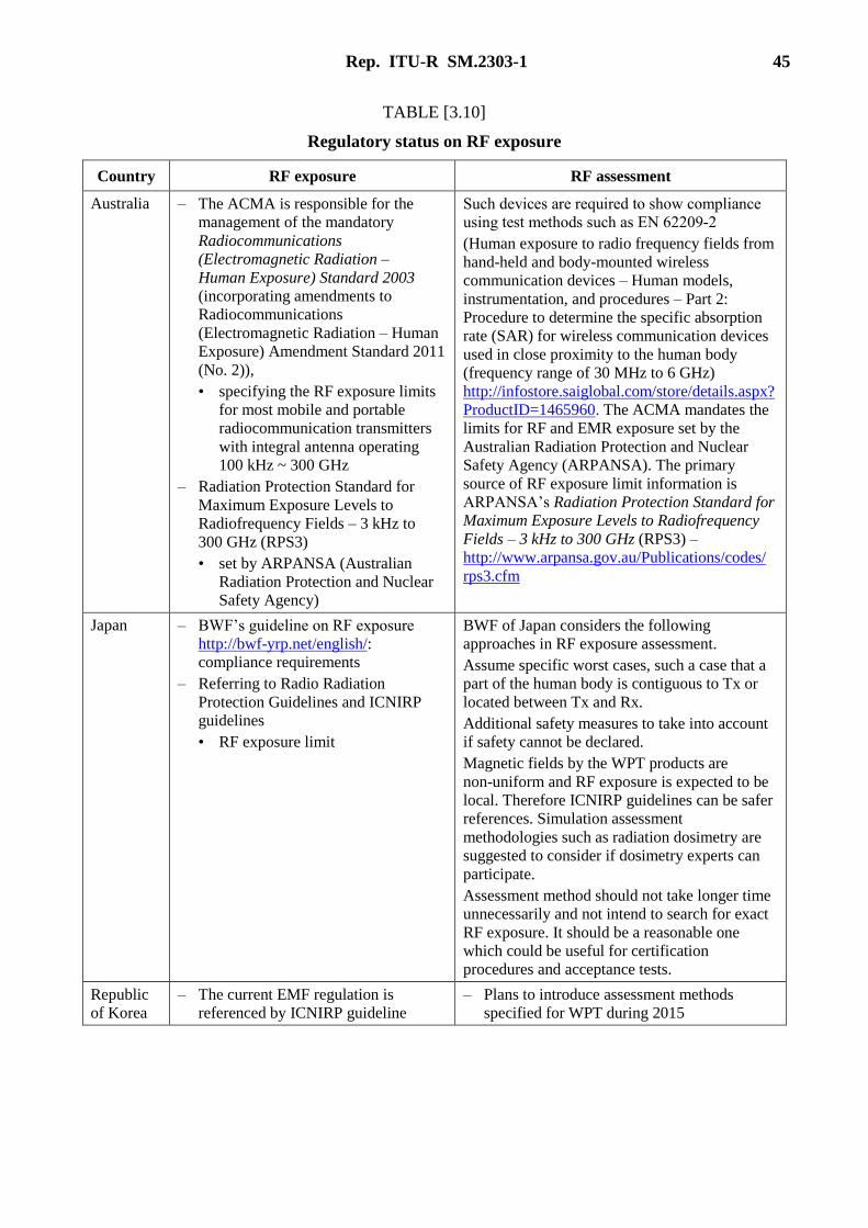
Rep. ITU-R SM.2303-1 45
TABLE [3.10]
Regulatory status on RF exposure
Country RF exposure RF assessment
Australia – The ACMA is responsible for the
management of the mandatory
Radiocommunications
(Electromagnetic Radiation –
Human Exposure) Standard 2003
(incorporating amendments to
Radiocommunications
(Electromagnetic Radiation – Human
Exposure) Amendment Standard 2011
(No. 2)),
• specifying the RF exposure limits
for most mobile and portable
radiocommunication transmitters
with integral antenna operating
100 kHz ~ 300 GHz
– Radiation Protection Standard for
Maximum Exposure Levels to
Radiofrequency Fields – 3 kHz to
300 GHz (RPS3)
• set by ARPANSA (Australian
Radiation Protection and Nuclear
Safety Agency)
Such devices are required to show compliance
using test methods such as EN 62209-2
(Human exposure to radio frequency fields from
hand-held and body-mounted wireless
communication devices – Human models,
instrumentation, and procedures – Part 2:
Procedure to determine the specific absorption
rate (SAR) for wireless communication devices
used in close proximity to the human body
(frequency range of 30 MHz to 6 GHz)
http://infostore.saiglobal.com/store/details.aspx?
ProductID=1465960. The ACMA mandates the
limits for RF and EMR exposure set by the
Australian Radiation Protection and Nuclear
Safety Agency (ARPANSA). The primary
source of RF exposure limit information is
ARPANSA’s Radiation Protection Standard for
Maximum Exposure Levels to Radiofrequency
Fields – 3 kHz to 300 GHz (RPS3) –
http://www.arpansa.gov.au/Publications/codes/
rps3.cfm
Japan – BWF’s guideline on RF exposure
http://bwf-yrp.net/english/:
compliance requirements
– Referring to Radio Radiation
Protection Guidelines and ICNIRP
guidelines
• RF exposure limit
BWF of Japan considers the following
approaches in RF exposure assessment.
Assume specific worst cases, such a case that a
part of the human body is contiguous to Tx or
located between Tx and Rx.
Additional safety measures to take into account
if safety cannot be declared.
Magnetic fields by the WPT products are
non-uniform and RF exposure is expected to be
local. Therefore ICNIRP guidelines can be safer
references. Simulation assessment
methodologies such as radiation dosimetry are
suggested to consider if dosimetry experts can
participate.
Assessment method should not take longer time
unnecessarily and not intend to search for exact
RF exposure. It should be a reasonable one
which could be useful for certification
procedures and acceptance tests.
Republic
of Korea
– The current EMF regulation is
referenced by ICNIRP guideline
– Plans to introduce assessment methods
specified for WPT during 2015
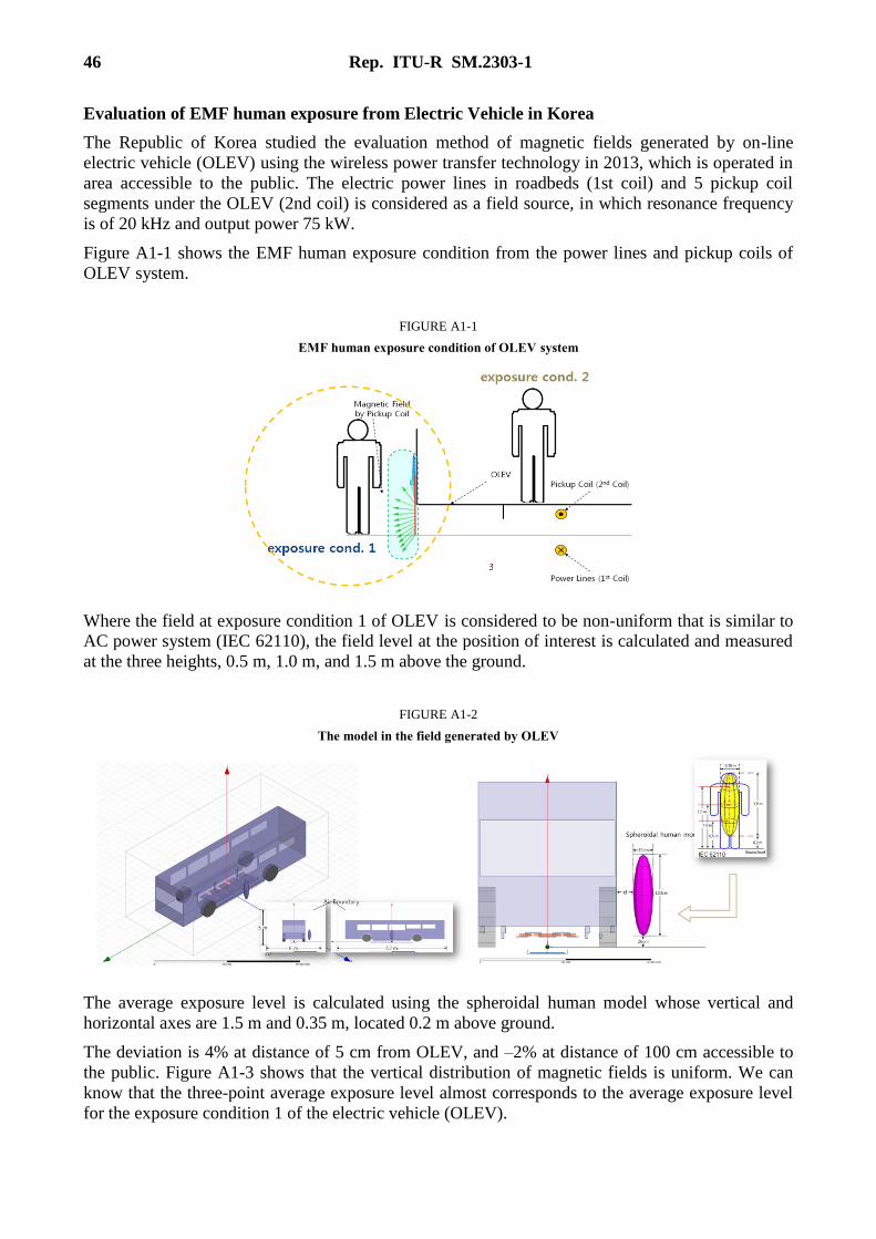
46 Rep. ITU-R SM.2303-1
Evaluation of EMF human exposure from Electric Vehicle in Korea
The Republic of Korea studied the evaluation method of magnetic fields generated by on-line
electric vehicle (OLEV) using the wireless power transfer technology in 2013, which is operated in
area accessible to the public. The electric power lines in roadbeds (1st coil) and 5 pickup coil
segments under the OLEV (2nd coil) is considered as a field source, in which resonance frequency
is of 20 kHz and output power 75 kW.
Figure A1-1 shows the EMF human exposure condition from the power lines and pickup coils of
OLEV system.
FIGURE A1-1
EMF human exposure condition of OLEV system
Where the field at exposure condition 1 of OLEV is considered to be non-uniform that is similar to
AC power system (IEC 62110), the field level at the position of interest is calculated and measured
at the three heights, 0.5 m, 1.0 m, and 1.5 m above the ground.
FIGURE A1-2
The model in the field generated by OLEV
The average exposure level is calculated using the spheroidal human model whose vertical and
horizontal axes are 1.5 m and 0.35 m, located 0.2 m above ground.
The deviation is 4% at distance of 5 cm from OLEV, and –2% at distance of 100 cm accessible to
the public. Figure A1-3 shows that the vertical distribution of magnetic fields is uniform. We can
know that the three-point average exposure level almost corresponds to the average exposure level
for the exposure condition 1 of the electric vehicle (OLEV).

Rep. ITU-R SM.2303-1 47
FIGURE A1-3
The calculated magnetic field distributions at each distances from OLEV
From the numerical analysis, the three-point (at the three heights, 0.5 m, 1.0 m, and 1.5 m above the
ground) average exposure level represents the average exposure level over the entire human body,
which is evaluated as 2.1 A/m, 40% less than the the technical criteria of RF exposure.
The magnetic field strength at exposure condition 2 of each seat inside OLEV is assessed and the
evaluation values are represented as in Fig. A1-4.
FIGURE A1-4
The calculated magnetic field distributions at each distances from OLEV
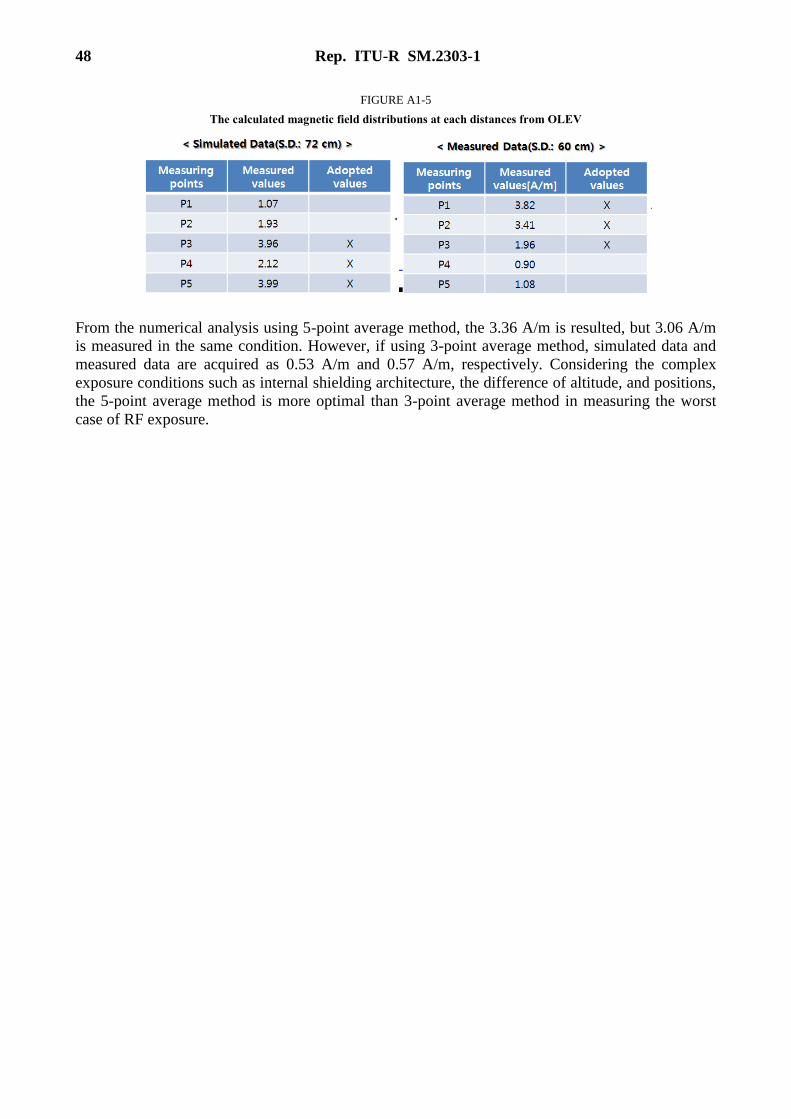
48 Rep. ITU-R SM.2303-1
FIGURE A1-5
The calculated magnetic field distributions at each distances from OLEV
From the numerical analysis using 5-point average method, the 3.36 A/m is resulted, but 3.06 A/m
is measured in the same condition. However, if using 3-point average method, simulated data and
measured data are acquired as 0.53 A/m and 0.57 A/m, respectively. Considering the complex
exposure conditions such as internal shielding architecture, the difference of altitude, and positions,
the 5-point average method is more optimal than 3-point average method in measuring the worst
case of RF exposure.
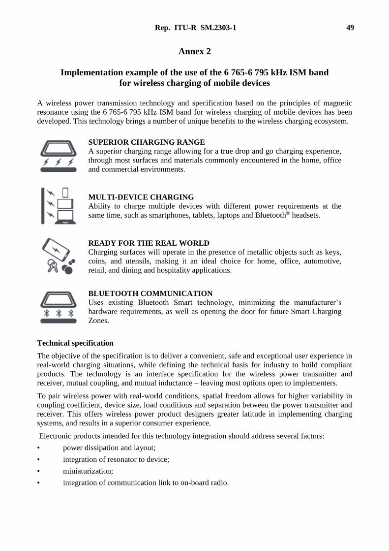
Rep. ITU-R SM.2303-1 49
Annex 2
Implementation example of the use of the 6 765-6 795 kHz ISM band
for wireless charging of mobile devices
A wireless power transmission technology and specification based on the principles of magnetic
resonance using the 6 765-6 795 kHz ISM band for wireless charging of mobile devices has been
developed. This technology brings a number of unique benefits to the wireless charging ecosystem.
SUPERIOR CHARGING RANGE
A superior charging range allowing for a true drop and go charging experience,
through most surfaces and materials commonly encountered in the home, office
and commercial environments.
MULTI-DEVICE CHARGING
Ability to charge multiple devices with different power requirements at the
same time, such as smartphones, tablets, laptops and Bluetooth® headsets.
READY FOR THE REAL WORLD
Charging surfaces will operate in the presence of metallic objects such as keys,
coins, and utensils, making it an ideal choice for home, office, automotive,
retail, and dining and hospitality applications.
BLUETOOTH COMMUNICATION
Uses existing Bluetooth Smart technology, minimizing the manufacturer’s
hardware requirements, as well as opening the door for future Smart Charging
Zones.
Technical specification
The objective of the specification is to deliver a convenient, safe and exceptional user experience in
real-world charging situations, while defining the technical basis for industry to build compliant
products. The technology is an interface specification for the wireless power transmitter and
receiver, mutual coupling, and mutual inductance – leaving most options open to implementers.
To pair wireless power with real-world conditions, spatial freedom allows for higher variability in
coupling coefficient, device size, load conditions and separation between the power transmitter and
receiver. This offers wireless power product designers greater latitude in implementing charging
systems, and results in a superior consumer experience.
Electronic products intended for this technology integration should address several factors:
• power dissipation and layout;
• integration of resonator to device;
• miniaturization;
• integration of communication link to on-board radio.

50 Rep. ITU-R SM.2303-1
Designers may specify and source their own implementation of the required out-of-band radios,
power amplifiers, DC-to-DC converters, rectifiers, microprocessors – discrete or integrated – and
assemble them as they require.
As long as the components conform to the specification, they can utilize any topology.
The specification reserves only the interfaces and model of transmitter resonator to be used in the
system.
The below figure illustrates the basic wireless power transmission system configuration between a
Power Transmitting Unit (PTU) and a Power Receiving Unit (PRU). The PTU can be expanded to
serve multiple independent PRUs. The PTU comprises three main functional units which are a
resonator and matching unit, a power conversion unit, and a signalling and control unit (MCU).
The PRU also comprises three main functional units like the PTU.
As shown in the above figure, the Transmitting Resonator (Tx Resonator) uses 6 780 kHz
(±15 kHz) to transmit power from the PTU to the PRU. Bluetooth SmartTM at 2.4 GHz band is used
for 2-way communication in a channel outside of the frequencies used to transmit power and
provides a reliable communication channel between the wireless power receivers and the charging
surfaces.
The specification provides for many categories of PRU and classes of PTU based on the power
delivered using the 6 780 kHz band, they range from a low power charging unit for small device
that can require only a few watts to larger devices that require many watts. Shown in the below
tables are PTU classes and PRU categories based on a draft Baseline System Specification, new
categories/classification are being developed.
PTX_IN
PRX_OUT
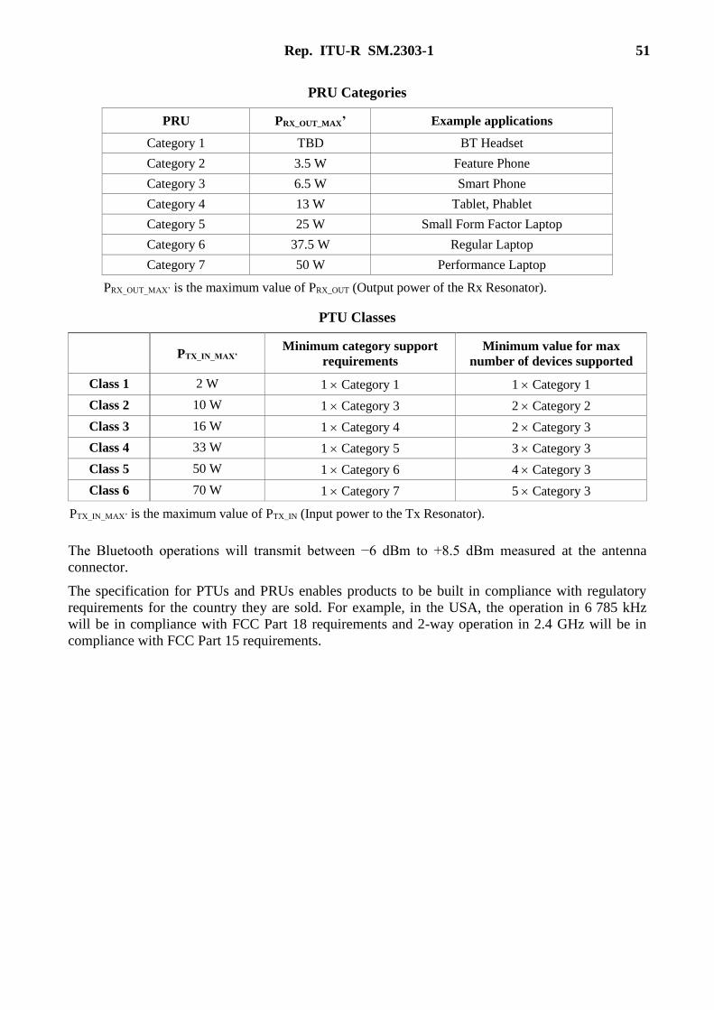
Rep. ITU-R SM.2303-1 51
PRU Categories
PRU PRX_OUT_MAX’ Example applications
Category 1 TBD BT Headset
Category 2 3.5 W Feature Phone
Category 3 6.5 W Smart Phone
Category 4 13 W Tablet, Phablet
Category 5 25 W Small Form Factor Laptop
Category 6 37.5 W Regular Laptop
Category 7 50 W Performance Laptop
PRX_OUT_MAX’ is the maximum value of PRX_OUT (Output power of the Rx Resonator).
PTU Classes
PTX_IN_MAX’ Minimum category support
requirements
Minimum value for max
number of devices supported
Class 1 2 W 1 Category 1 1 Category 1
Class 2 10 W 1 Category 3 2 Category 2
Class 3 16 W 1 Category 4 2 Category 3
Class 4 33 W 1 Category 5 3 Category 3
Class 5 50 W 1 Category 6 4 Category 3
Class 6 70 W 1 Category 7 5 Category 3
PTX_IN_MAX’ is the maximum value of PTX_IN (Input power to the Tx Resonator).
The Bluetooth operations will transmit between −6 dBm to +8.5 dBm measured at the antenna
connector.
The specification for PTUs and PRUs enables products to be built in compliance with regulatory
requirements for the country they are sold. For example, in the USA, the operation in 6 785 kHz
will be in compliance with FCC Part 18 requirements and 2-way operation in 2.4 GHz will be in
compliance with FCC Part 15 requirements.

52 Rep. ITU-R SM.2303-1
Annex 3
Measurement data of radiated noise and conductive noise from WPT systems
TABLE OF CONTENTS
Page
1 Introduction .................................................................................................................... 53
2 Measurement models and measurement methods .......................................................... 53
2.1 Measurement model and measurement method for WPT system for EV
charging .............................................................................................................. 53
2.2 Measurement model and measurement method for mobile devices, portable
devices, and home appliances ............................................................................. 56
3 Target radiation emission limit set by BWF ................................................................... 58
3.1 Target radiation emission limit for WPT system for EV charging ..................... 58
3.2 Target radiation emission limit for mobile and portable devices using
magnetic resonance technology .......................................................................... 59
3.3 Target radiation emission limit for home appliances using magnetic inductive
technology ........................................................................................................... 59
3.4 Target radiation emission limit for mobile and portable devices using
capacitive coupling technology .......................................................................... 60
4 Measurement results of radiated noise and conductive noise ......................................... 61
4.1 Measurement results for WPT system for EV charging ..................................... 61
4.2 Measurement results for mobile and portable devices using magnetic
resonance technology .......................................................................................... 66
4.3 Measurement results for home appliances using magnetic inductive
technology ........................................................................................................... 69
4.4 Measurement results for mobile and portable devices using capacitive
coupling technology ............................................................................................ 73

Rep. ITU-R SM.2303-1 53
1 Introduction
This Annex provides measured data of radiated noise and conductive noise from the WPT systems
under the consideration of the new rulemaking in Japan. The systems are listed as follows and
fundamental parameters are shown in Table 7.1. Detailed information on the coexistence studies of
the systems are introduced in Doc. 1A/152:
(1) WPT system for passenger EV (Electric Vehicle) charging;
(2) WPT system for mobile and portable devices using magnetic resonance technology;
(3) WPT system for home appliances and office equipment using magnetic inductive
technology, and
(4) WPT system for mobile and portable devices using capacitive coupling technology.
2 Measurement models and measurement methods
Measurement models and measurement methods for radiated noise and conductive noise from WPT
systems were discussed and determined by WPT-WG under the Subcommittee on Electromagnetic
Environment for Radio-wave Utilization of the Ministry of Internal Affairs and Communications
(MIC). The following measurements were conducted:
(1) Radiated noise in the frequency range from 9 kHz to 30 MHz:
Magnetic field strength is measured by using loop antennas. Electric field strength is
obtained by simple translation using the characteristic impedance of plane wave, 377 ohm.
(2) Radiated noise in the frequency range from 30 MHz to 1 GHz:
Electric field strength is measured by using bi-conical antennas or log-periodic dipole
arrays. In the case of portable devices applications, the measured frequency range is
expanded to 6 GHz.
(3) Conductive noise in the frequency range from 9 kHz to 30 MHz:
Conductive noise radiated from power supply lines is measured. In this measurement, EUT
(Equipment under Test) should be connected to AMN (Artificial Mains Network).
2.1 Measurement model and measurement method for WPT system for EV charging
Figures A3-1 and A3-2 describe measurement methods for radiated noise from WPT systems for
EV charging. Figure A3-1 is in the frequency range from 9 kHz to 30 MHz. Figure A3-2 is in the
frequency range from 30 MHz to 1 GHz. Figure A3-3 describes the top view of EUT and its
arrangement for radiated noise measurement. In this measurement method, CISPR 16-2-3 “Radiated
disturbance measurements” is referred. Figure A3-4 describes an imitated car body used in this
measurement. This imitated car model was proposed to IEC TC 69/PT 61980, in which an
international standard regarding WPT systems for EV charging. Figure A3-5 describes the top view
of EUT and its arrangement for conductive noise measurement. In these measurements, the
transmission power is defined as power level measured at the input port of RF power supply
equipment or the primary coil.

54 Rep. ITU-R SM.2303-1
FIGURE A3-1
Measurement methods for radiated noise from WPT systems for EV charging,
in the frequency range from 9 kHz to 30 MHz
R pe ort SM.2303-A3-01
(10 m or 30 m) 1.5 m
Maximum radiated direction should beset by rotating EUT.
1.0
m1
.0 m
0.1
m
0.1
m
Turn table
Measurement distance isdefined as length betweenthe center of a loopantenna and the frontface of EUT.
WPT system(EUT)
Insulation panel
Powersupply
equipment
FIGURE A3-2
Measurement methods for radiated noise from WPT systems for EV charging,
in the frequency range from 30 MHz to 1 GHz
R pe ort SM.2303-A3-02
(10 m or 30 m)
Maximum radiated direction should beset by rotating EUT.
0.1
m
Turn table
The height ofreceived antennas isadjusted to measurethe maximumradiated noise.
WPT system(EUT)
Insulation panel
Powersupply
equipment
0.1
m
Bi-conicalantenna
Log-periodicdipole array

Rep. ITU-R SM.2303-1 55
FIGURE A3-3
Top view of EUT and its arrangement for radiated noise measurement
R pe ort SM.2303-A3-02
(0.8 m)
Definition of EUT
Measurement, distance is definedas length between a receivedantenna and the edge of a primarycoil (Tx-coil)
Primary coil/secondary
coil
Imitated car body, primary coil(Tx-coil) and RF power supplyequipment are insulated fromground plane by using 0.1 mthickness insulation panel.
Rf powersupply
Turn table
Insulation panel
Imitated car body
Power supply network
FIGURE A3-4
Configuration of the imitated car body
R pe ort SM.2303-A3-04
MetallicVehicle system
Communication unit
Primarychargingequipment
Load
250 m
m
1) Metal box2) Window3) Non conductive material support4) Coil set5) Load set
2 coil unitnd
Non metallic
Communicationunit
Charge equipment
(4)
(4)
(5)
(1)
(2)
(3)(3)
125
0 m
m
1 700 mm
1 000 mm 350 mm350 mm
40
0 m
m1
00
0 m
m 1 7
00 m
m
1 700 mm
(3) (3)
(3) (3)
(1)
(4), (5)
a) Side view
Primary coil unit
b) Top view
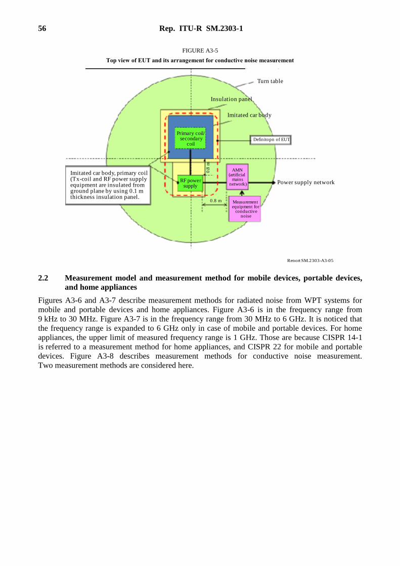
56 Rep. ITU-R SM.2303-1
FIGURE A3-5
Top view of EUT and its arrangement for conductive noise measurement
R pe ort SM.2303-A3-05
Turn table
Insulation panel
Definitopn of EUT
RF powersupply
AMN(artificial
mainsnetwork)
0.8
m
Imitated car body
Power supply network
0.8 m
Primary coil/secondary
coil
Measurementequipment for
conductivenoise
Imitated car body, primary coil(Tx-coil and RF power supplyequipment are insulated fromground plane by using 0.1 mthickness insulation panel.
2.2 Measurement model and measurement method for mobile devices, portable devices,
and home appliances
Figures A3-6 and A3-7 describe measurement methods for radiated noise from WPT systems for
mobile and portable devices and home appliances. Figure A3-6 is in the frequency range from
9 kHz to 30 MHz. Figure A3-7 is in the frequency range from 30 MHz to 6 GHz. It is noticed that
the frequency range is expanded to 6 GHz only in case of mobile and portable devices. For home
appliances, the upper limit of measured frequency range is 1 GHz. Those are because CISPR 14-1
is referred to a measurement method for home appliances, and CISPR 22 for mobile and portable
devices. Figure A3-8 describes measurement methods for conductive noise measurement.
Two measurement methods are considered here.
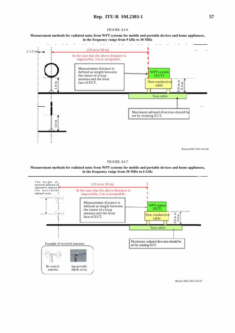
Rep. ITU-R SM.2303-1 57
FIGURE A3-6
Measurement methods for radiated noise from WPT systems for mobile and portable devices and home appliances,
in the frequency range from 9 kHz to 30 MHz
R pe ort SM.2303-A3-06
(10 m or 30 m) 1.5 m
Maximum radiated direction should beset by rotating EUT.
1.0
m
Turn table
Measurement distance isdefined as length betweenthe center of a loopantenna and the frontface of EUT.
WPT system(EUT)
0.8
m o
r0
.4 m
1.0
m
Non conductivetable
In the case that the above distance isimpossible, 3 m is acceptable.
FIGURE A3-7
Measurement methods for radiated noise from WPT systems for mobile and portable devices and home appliances,
in the frequency range from 30 MHz to 6 GHz
R pe ort SM.2303-A3-07
(10 m or 30 m)
Maximum radiated direction should beset by rotating EUT.
T h e h e i gh t ofreveived antennas isadjusted to measuret h e m a x i m u m
radiated noise.
Turn table
Measurement distance isdefined as length betweenthe center of a loopantenna and the frontface of EUT.
WPT system(EUT)
0.8
m o
r0
.4 m
Bi-conicalantenna
Non conductivetable
In the case that the above distance isimpossible, 3 m is acceptable.
log-periodicdipole array
Example of received antennas
58 Rep. ITU-R SM.2303-1
FIGURE A3-8
Measurement methods for conductive noise measurement
R pe ort SM.2303-A3-07
Shielded room
AMN(CISPR16-2-1)
0.8
m
(horizontal ground plane)
(ver
tic
al g
rou
nd p
lan
e)
0.4
m
0.8 m
0.4 m
0. 8
m
AMN(CISPR16-2-1)
EUT
EUT
3 Target radiation emission limit set by BWF
The radiation emission limit for a new Japanese regulation is under discussion in WPT-WG, MIC.
But, Broadband Wireless Forum (BWF), Japan, has already set the target radiation emission limit as
tentative values to discuss co-existing conditions for other wireless systems. The fundamental
viewpoints for the target radiation emission limits are as follows;
(1) Target radiated noise limits are set only in the frequency range from 9 kHz to 30 MHz.
Both of electric field strength limits and magnetic field strength limits are described here.
(2) Target radiated noise limits of electric field strength are firstly considered, because BWF
refers to the current Japanese national radio regulation and its radiated noise limits are
basically determined by electric field strength. Translation of electric field strength to
magnetic field strength is done by calculation using the characteristic impedance of TEM
wave (plane wave), 377 ohm.
(3) BWF does not set the target limits of radiated noise over 30 MHz and conductive noise.
Next, the target radiation emission limits for each WPT system are described. It should be noted
that these are tentative and are under discussion.
3.1 Target radiation emission limit for WPT system for EV charging
Tentative target radiated noise limit for WPT frequency range was proposed by reference to FCC
Part 18 Subpart C as an international rule and by measurement results of developed WPT systems.
Tentative target radiated noise limit for the other frequency range was proposed on the basis of the
Japanese radio regulation applied to inductive cooking equipment as a commonly used magnetic
inductive application.
(1) Tentative target limit of radiated electric field noise
(a) WPT frequency range (frequency range used for power transmission)
3 kW – Tx Power : 36.7 mV/m@30m (91.3 dBμV/m@30m)
7.7 kW – Tx Power : 58.9 mV/m@30m (95.4 dBμV/m@30m)

Rep. ITU-R SM.2303-1 59
(b) Frequency range from 526.5-1 606.5 kHz
: 30 μV/m@30m (29.5 dBμV/m@30m)
(c) Frequency range expect for the above frequency range
: 200 μV/m@30m (46.0 dBμV/m@30m)
(2) Tentative target limit of radiated magnetic field noise
(a) WPT frequency range (frequency range used for power transmission)
3 kW – Tx Power : 97.5 μA/m@30m (39.8 dBμA/m@30m)
7.7 kW – Tx Power : 156 μA/m@30m (43.9 dBμA/m@30m)
(b) Frequency range from 526.5-1606.5 kHz
: 0.0796 μA/m@30m (−22.0 dBμA/m@30m)
(c) Frequency range expect for the above frequency range
: 0.531 μA/m@30m (−5.51 dBμA/m@30m)
3.2 Target radiation emission limit for mobile and portable devices using magnetic
resonance technology
Tentative target radiated noise limit for WPT frequency range was proposed on the basis of
measurement results of developed WPT systems. Tentative target radiated noise limit for the other
frequency range was proposed on the basis of the Japanese radio regulation applied to inductive
cooking equipment as a commonly used magnetic inductive application.
(1) Tentative target limit of radiated electric field noise
(a) WPT frequency range (frequency range used for power transmission)
: 100 mV/m@30m (100 dBμV/m@30m)
(b) Frequency range from 526.5-1 606.5 kHz
: 30 μV/m@30m (29.5 dBμV/m@30m)
(c) Frequency range expect for the above frequency range
: 100 μV/m@30m (40.0 dBμV/m@30m)
(2) Tentative target limit of radiated magnetic field noise
(a) WPT frequency range (frequency range used for power transmission)
: 265.3 μA/m@30m (48.5dB μA/m@30m)
(b) Frequency range from 526.5-1 606.5 kHz
: 0.0796 μA/m@30m (−22.0 dBμA/m@30m)
(c) Frequency range expect for the above frequency range
: 0.265 μA/m@30m (−11.5dB μA/m@30m)
3.3 Target radiation emission limit for home appliances using magnetic inductive
technology
Tentative target radiated noise limit for WPT frequency range was proposed on the basis of
measurement results of developed WPT systems. Tentative target radiated noise limit for the other
frequency range was proposed on the basis of the Japanese radio regulation applied to inductive
cooking equipment as a commonly used magnetic inductive application.

60 Rep. ITU-R SM.2303-1
(1) Tentative target limit of radiated electric field noise
(a) WPT frequency range (frequency range used for power transmission)
: 1 mV/m@30m (60 dBμV/m@30m)
(b) Frequency range from 526.5-1 606.5 kHz
: 30 μV/m@30m (29.5 dBμV/m@30m)
(c) Frequency range expect for the above frequency range
: 173 μV/m@30m (44.8 dBμV/m@30m)
(2) Tentative target limit of radiated magnetic field noise
(a) WPT frequency range (frequency range used for power transmission)
: 2.66 μA/m@30m (8.5 dBμA/m@30m)
(b) Frequency range from 526.5-1 606.5 kHz
: 0.0796 μA/m@30m (−22.0 dBμA/m@30m)
(c) Frequency range expect for the above frequency range
: 0.459 μA/m@30m (−6.7 dBμA/m@30m)
3.4 Target radiation emission limit for mobile and portable devices using capacitive
coupling technology
The tentative target radiated noise limit for WPT frequency range was proposed on the basis of
measurement results of developed WPT systems. The tentative target radiated noise limit for the
other frequency range was proposed on the basis of the Japanese radio regulation applied to
inductive cooking equipment as a commonly used magnetic inductive application.
(1) Tentative target limit of radiated electric field noise
(a) WPT frequency range (frequency range used for power transmission)
: 100 μV/m@30m (40 dB μV/m@30m)
(b) Frequency range from 526.5-1 606.5 kHz
: 30 μV/m@30m (29.5 dBμV/m@30m)
(c) Frequency range expect for the above frequency range
: 100 μV/m@30m (40 dB μV/m@30m)
(2) Tentative target limit of radiated magnetic field noise
(a) WPT frequency range (frequency range used for power transmission)
: 0.265 μA/m@30m (−11.5 dB μA/m@30m)
(b) Frequency range from 526.5-1606.5 kHz
: 0.0796 μA/m@30m (−22.0 dBμA/m@30m)
(c) Frequency range expect for the above frequency range
: 0.265 μA/m@30m (−11.5 dB μA/m@30m)

Rep. ITU-R SM.2303-1 61
4 Measurement results of radiated noise and conductive noise
Measurement results of radiated noise, conductive noise and related measurements for each WPT
system are described. WPT systems measured here are equipment for test and under development.
4.1 Measurement results for WPT system for EV charging
(1) Overview of test equipment
Two pieces of test equipment were prepared for this measurement as shown in Table A3-1. In test
equipment A, WPT frequency is 120 kHz and planer circular Tx and Rx coils are used. In test
equipment B, WPT frequency is 85 kHz and solenoid type coils are used for both of Tx and Rx.
Also, test equipment B includes devices to suppress higher order harmonics of WPT frequency.
Photographs of each test equipment are described in Figs A3-9 and A3-10, respectively.
TABLE A3-1
Overview of test equipment for EV charging
WPT system EV charging
WPT technology Magnetic resonance
WPT frequency Test equipment A: 120 kHz
Test equipment B: 85 kHz
Condition for WPT Transfer power: 3 kW
Power transfer distance: 150 mm
FIGURE A3-9
Test equipment A
R pe ort SM.2303-A3-09
Tx coil (planar circular type)
Imitated car body

62 Rep. ITU-R SM.2303-1
FIGURE A3-10
Test equipment B
R pe ort SM.2303-A3-10
Imitated car body
Tx coil (solenoid type)Rectifier and matching circuit
(2) Measurement results of radiated noise
Radiated noise from each test equipment was measured in shielded anechoic chamber. Measured
distance is 10 m. When field strength at 30 m is described, the field strength is obtained by the
following translation rule which is published in Japanese radio regulation.
[Attenuation factor due to measurement distance from 10 m to 30 m]
Lower frequency than 526.5 kHz: 1/27
From 526.5-1 606.5 kHz: 1/10
Over 1 606.5 kHz to 30 MHz: 1/6
Measurement results in the frequency range from 9 kHz to 30 MHz are shown in Figs A3-11 and
A3-12. Figure A3-13 describes measurement result of higher order harmonics of each test
equipment. The results of these measurements show that test equipment B clears the tentative target
limit of radiated noise. Test equipment A clears the tentative target limit for WPT frequency, and
does not clear the tentative target limit of the other frequency range. But, by including the suitable
devices to suppress high frequency noise, it is thought that the tentative target limit can be cleared.
Measurement results in the frequency range from 30 MHz to 1 GHz are shown in Figs A3-14
and A3-15.

Rep. ITU-R SM.2303-1 63
FIGURE A3-11
Radiated noise of test equipment A (9 kHz - 30 MHz, peak value)
R pe ort SM.2303-A3-11
60M
agne
tic
fiel
d st
ren
gth
at
30 m
(d
BA
/m)
Magnetic field Hx
1 kHz
Frequency
40
20
0
–20
–40
–6010 kHz 100 kHz 1 MHz 10 MHz
Noise from other equipment
Magnetic field Hy
Target limit
FIGURE A3-12
Radiated noise of test equipment B (9 kHz - 30 MHz, peak value)
R pe ort SM.2303-A3-12
60
Mag
neti
c fi
eld
stre
ng
th a
t 30
m (
dB
A/m
)
Magnetic field Hx
1 kHz
Frequency
40
20
0
–20
–40
–6010 kHz 100 kHz 1 MHz 10 MHz
Noise from other equipment
Magnetic field Hy
Target limit
64 Rep. ITU-R SM.2303-1
FIGURE A3-13
Measurement results of higher order harmonics (Quasi-peak value)
R pe ort SM.2303-A3-13
60
Mag
neti
c fi
eld
stre
ng
th a
t 10
m (
dB
A/m
)
Test equipment B
Frequency (kHz)
50
20
40
10
–10
–20700
WPT frequency
Test equipment A
WPT frequency
2nd 3rd 3rd
2nd4th 5th
4th
5th
7th
6005004003002001000
0
30
70
80
FIGURE A3-14
Radiated noise of test equipment A (30 MHz - 1 GHz, peak value)
R pe ort SM.2303-A3-14
80
Ele
ctri
c fi
eld
stre
ngt
h a
t 10
m (
dB
A/m
)
Electric field Ex
10
Frequency (MHz)
70
60
50
0100 1 000
Electric field Ey
40
30
20
10

Rep. ITU-R SM.2303-1 65
FIGURE A3-15
Radiated noise of test equipment B (30 MHz - 1 GHz, peak value)
R pe ort SM.2303-A3-15
80E
lect
ric
fiel
d st
ren
gth
at
10 m
(d
BA
/m)
Electric field Ex
10
Frequency (MHz)
70
60
50
0100 1 000
Electric field Ey
40
30
20
10
(3) Measurement results of conductive noise
Measurement results of conductive noise in the frequency range from 30 MHz to 1 GHz are shown
in Figs A3-16 and A3-17.
FIGURE A3-16
Conductive noise of test equipment A (9 kHz - 30 MHz, peak value)
R pe ort SM.2303-A3-16
120
Con
duct
ive
no
ise
vol
tag
e (d
BV
)
1 kHz
Frequency
100
60
80
0100 kHz 10 MHz
40
20
10 kHz 1 MHz
66 Rep. ITU-R SM.2303-1
FIGURE A3-17
Conductive noise of test equipment B (9 kHz - 30 MHz, peak value)
R pe ort SM.2303-A3-17
120
Con
duct
ive
no
ise
vol
tag
e (d
BV
)
1 kHz
Frequency (MHz)
100
80
0100 kHz 10 MHz
60
40
20
1 MHz10 kHz
4.2 Measurement results for mobile and portable devices using magnetic resonance
technology
(1) Overview of test equipment
Table A3-2 shows the overview of the test equipment for mobile and portable devices using
magnetic resonance technology. WPT frequency is 6.78 MHz. Figure A3-18 describes a typical coil
structure for this test equipment.
The portable device measured here includes this coil structure inside. Transmission power of this
test equipment is 16.8 W. In measurement results shown next, the transmission power is converted
to 100 W, and measurement distance is translated to 30 m using the translation factor mentioned in
§ 4.1(2). It is noted that test equipment includes no devices to suppress higher order harmonics of
WPT frequency.
TABLE A3-2
Overview of test equipment for mobile and portable devices using magnetic resonance
WPT system Mobile and IT devices
WPT technology Magnetic resonance
WPT frequency 6.78 MHz
Condition for WPT Transfer power: 16.8 W
Power transfer distance: several centimetres
Rep. ITU-R SM.2303-1 67
FIGURE A3-18
Typical coil structure for test equipment for mobile and portable devices using magnetic resonance
R pe ort SM.2303-A3-18
Tx coil165 165 mm
Rx coil110 110 mm
Styrene foam
RF cable to Rx coil
RF cable to Tx coil
(2) Measurement results of radiated noise
Radiated noise from test equipment was measured in shielded anechoic chamber. Measurement
results in the frequency range from 9 kHz to 30 MHz, from 30 MHz to 1 GHz, and from 1 GHz
to 6 GHz are shown in Figs A3-19, A-20 and A3-21, respectively. Also, Fig. A3-22 describes
measurement result of higher order harmonics of this test equipment. As results of these
measurements, it is found that this test equipment clears the tentative target limit of radiated noise
for WPT frequency. And also, it is recognized that there is no emission noise over 1 GHz.
FIGURE A3-19
Radiated noise of test equipment (9 kHz - 30 MHz, peak value)
R pe ort SM.2303-A3-19
60
Mag
neti
c fi
eld
stre
ng
th a
t 30
m (
dB
A/m
)
Magnetic field Hx
1 kHz
Frequency
40
20
0
–20
–40
–6010 kHz 100 kHz 1 MHz 10 MHz
Magnetic field Hy
Target limit
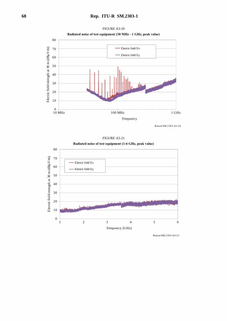
68 Rep. ITU-R SM.2303-1
FIGURE A3-20
Radiated noise of test equipment (30 MHz - 1 GHz, peak value)
R pe ort SM.2303-A3-20
60
Ele
ctri
c fi
eld
stre
ngt
h a
t 30
m (
dB
V/m
)
Electric field Ex
10 MHz
Frequency
70
50
40
30
10
01 GHz
Electric field Ey
20
80
100 MHz
FIGURE A3-21
Radiated noise of test equipment (1-6 GHz, peak value)
R pe ort SM.2303-A3-21
60
Ele
ctri
c fi
eld
stre
ngt
h a
t 30
m (
dB
V/m
) Electric field Ex
1
Frequency (GHz)
70
50
40
30
10
0
Electric field Ey
20
80
2 3 4 5 6

Rep. ITU-R SM.2303-1 69
FIGURE A3-22
Measurement results of higher order harmonics (Quasi-peak value)
R pe ort SM.2303-A3-22
60M
agne
tic
fiel
d st
ren
gth
at
10 m
(d
BA
/m)
Magnetic field Hx
0
Frequency (MHz)
70
50
40
30
10
–20
Magnetic field Hy
20
5
–10
0
10 15 302520
(3) Measurement results of conductive noise
Measurement results of conductive noise in the frequency range from 30 MHz to 1 GHz are shown
in Fig. A3-23.
FIGURE A3-23
Conductive noise of test equipment (9 kHz - 30 MHz, peak value)
R pe ort SM.2303-A3-23
Con
duct
ive
nois
e v
olta
ge
(dB
V)
Frequency (Hz)
120
100
80
40
0
60
20
1 kHz 100 kHz 10 MHz1 MHz10 kHz
4.3 Measurement results for home appliances using magnetic inductive technology
(1) Overview of test equipment
Table A3-3 shows the overview of the test equipment for home appliances using magnetic inductive
technology. There are two coil structures for this WPT system as shown in Fig. A3-24. WPT
frequency is 23.4 kHz and 94 kHz. Transmission powers are 1.5 kW for test equipment A, and
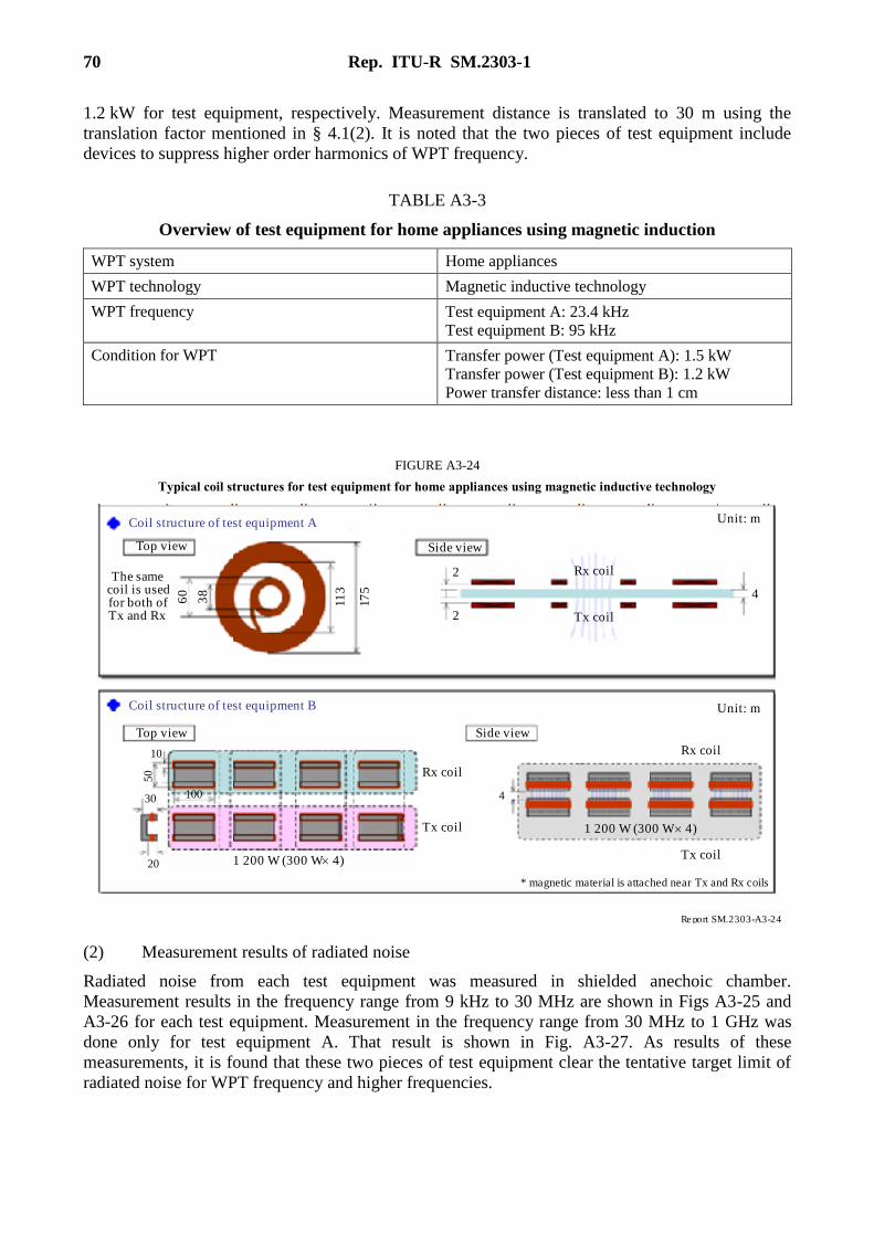
70 Rep. ITU-R SM.2303-1
1.2 kW for test equipment, respectively. Measurement distance is translated to 30 m using the
translation factor mentioned in § 4.1(2). It is noted that the two pieces of test equipment include
devices to suppress higher order harmonics of WPT frequency.
TABLE A3-3
Overview of test equipment for home appliances using magnetic induction
WPT system Home appliances
WPT technology Magnetic inductive technology
WPT frequency Test equipment A: 23.4 kHz
Test equipment B: 95 kHz
Condition for WPT Transfer power (Test equipment A): 1.5 kW
Transfer power (Test equipment B): 1.2 kW
Power transfer distance: less than 1 cm
FIGURE A3-24
Typical coil structures for test equipment for home appliances using magnetic inductive technology
R pe ort SM.2303-A3-24
Tx coil
Coil structure of test equipment A
Coil structure of test equipment B
Top view
Top view
The samecoil is usedfor both ofTx and Rx
60
38
113
175
2
4
Rx coil
Side view
2
* magnetic material is attached near Tx and Rx coils
Side view
10
50
10030
1 200 W (300 W 4)
Tx coil
Rx coil
4
Tx coil
Rx coil
1 200 W (300 W 4)
Unit: m
Unit: m
20
(2) Measurement results of radiated noise
Radiated noise from each test equipment was measured in shielded anechoic chamber.
Measurement results in the frequency range from 9 kHz to 30 MHz are shown in Figs A3-25 and
A3-26 for each test equipment. Measurement in the frequency range from 30 MHz to 1 GHz was
done only for test equipment A. That result is shown in Fig. A3-27. As results of these
measurements, it is found that these two pieces of test equipment clear the tentative target limit of
radiated noise for WPT frequency and higher frequencies.
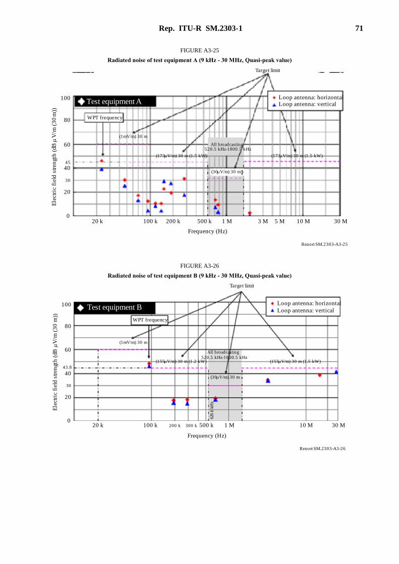
Rep. ITU-R SM.2303-1 71
FIGURE A3-25
Radiated noise of test equipment A (9 kHz - 30 MHz, Quasi-peak value)
R pe ort SM.2303-A3-25
Test equipment ALoop antenna: horizontal
20 k
All broadcasting520.5 kHz-1800.5 kHz
0
20
80
30
45
40
60
100
200 k100 k 1 M500 k 3 M 5 M 10 M 30 M
Frequency (Hz)
(30 V/m) 30 m
(173 V/m) 30 m (1.5 kW)(173 V/m) 30 m (1.5 kW)
(1mV/m) 30 m
Target limit
Loop antenna: vertical
Ele
ctri
c fi
eld
str
engt
h (d
B
V/m
(3
0 m
))
WPT frequency
FIGURE A3-26
Radiated noise of test equipment B (9 kHz - 30 MHz, Quasi-peak value)
R pe ort SM.2303-A3-26
Test equipment BLoop antenna: horizontal
20 k
All broadcasting
520.5 kHz-1800.5 kHz
0
20
80
30
43.8
40
60
100
300 k100 k 1 M500 k 10 M 30 M
Frequency (Hz)
(30 V/m) 30 m
(155 V/m) 30 m (1.5 kW)(155 V/m) 30 m (1.2 kW)
(1mV/m) 30 m
Target limit
Loop antenna: vertical
Ele
ctri
c fi
eld
str
engt
h (d
B
V/m
(3
0 m
))
WPT frequency
200 k
626
.6 k
Hz
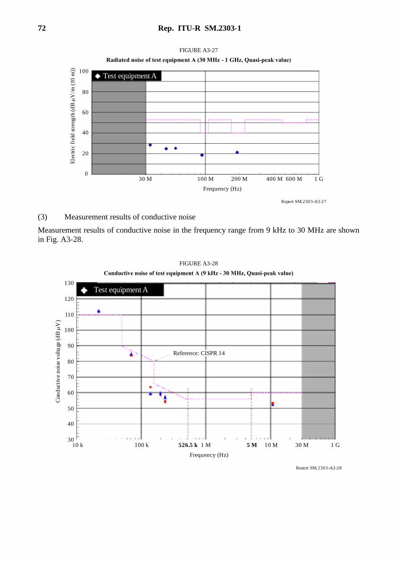
72 Rep. ITU-R SM.2303-1
FIGURE A3-27
Radiated noise of test equipment A (30 MHz - 1 GHz, Quasi-peak value)
R pe ort SM.2303-A3-27
Test equipment A
30 M0
20
80
40
60
100
100 M 200 M 1 G
Frequency (Hz)
Ele
ctri
c fi
eld
str
eng
th (
dB
V
/m (
10 m
))
400 M 600 M
(3) Measurement results of conductive noise
Measurement results of conductive noise in the frequency range from 9 kHz to 30 MHz are shown
in Fig. A3-28.
FIGURE A3-28
Conductive noise of test equipment A (9 kHz - 30 MHz, Quasi-peak value)
R pe ort SM.2303-A3-28
Test equipment A
100 k30
40
80
50
60
100
1 M 1 G
Frequency (Hz)
Con
duc
tiv
e n
oise
vol
tage
(d
B
V)
5 M 10 M10 k 30 M
70
90
110
120
130
526.5 k
Reference: CISPR 14
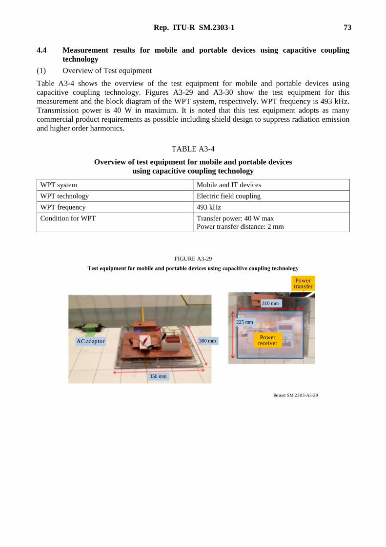
Rep. ITU-R SM.2303-1 73
4.4 Measurement results for mobile and portable devices using capacitive coupling
technology
(1) Overview of Test equipment
Table A3-4 shows the overview of the test equipment for mobile and portable devices using
capacitive coupling technology. Figures A3-29 and A3-30 show the test equipment for this
measurement and the block diagram of the WPT system, respectively. WPT frequency is 493 kHz.
Transmission power is 40 W in maximum. It is noted that this test equipment adopts as many
commercial product requirements as possible including shield design to suppress radiation emission
and higher order harmonics.
TABLE A3-4
Overview of test equipment for mobile and portable devices
using capacitive coupling technology
WPT system Mobile and IT devices
WPT technology Electric field coupling
WPT frequency 493 kHz
Condition for WPT Transfer power: 40 W max
Power transfer distance: 2 mm
FIGURE A3-29
Test equipment for mobile and portable devices using capacitive coupling technology
R pe ort SM.2303-A3-29
AC adaptor
350 mm
300 mm
310 mm
225 mm
Powerreceiver
Powertransfer

74 Rep. ITU-R SM.2303-1
FIGURE A3-30
Block diagram of WPT system for mobile and portable devices using capacitive coupling technology
R pe ort SM.2303-A3-30
AC adaptor
Receiver module
Downtransformer
Rectifyingcircuit
Voltageregulator
DC output
Target device
Electrode
Electrode
Return
Power transmission
Uptransformer
Controller
Overvoltageprotection
Inverter(amplifier)
DC input
Transmission module
DC
PWM
PWM
(2) Measurement results of radiated noise
Radiated noise from this test equipment was measured in shielded anechoic chamber. Measurement
results in the frequency range from 9 kHz to 30 MHz, from 30 MHz to 1 GHz, and 1 GHz to 6 GHz
are shown in Figs A3-31, A3-32, and A3-33, respectively. The results of the measurements in
Fig. A3-31 show that the radiated noise is less than the tentative target limit, which may be due to
the means to suppress radiation and emission.
FIGURE A3-31
Radiated noise (9 kHz - 30 MHz, peak value)
R pe ort SM.2303-A3-31
1.00
Frequency (MHz)
0.01
Target limit
0.10 10.0 30.0 1.000.01 0.10 10.0 30.0
Frequency (MHz)
0
20
110
50
70
Ele
ctr
ic f
ield
str
eng
th a
t 3m
(dB
(V
/m))
90
10
40
60
80
100
30
Peak value
Target limit
Peak valueLoop antenna X Loop antenna Y
110
Ele
ctr
ic f
ield
str
eng
th a
t 3m
(dB
(V
/m))
0
20
50
70
90
10
40
60
80
100
30

Rep. ITU-R SM.2303-1 75
FIGURE A3-32
Radiated noise (30 MHz - 1 GHz, peak and Quasi-peak value)
R pe ort SM.2303-A3-32
Frequency (MHz)
Peak valueE
lect
ric
fie
ld s
tren
gth
at
10
m (
dB
(V
/m))
100
Frequency (MHz)
30 50 1 000
Ele
ctri
c fi
eld
str
eng
th a
t 1
0 m
(dB
(V
/m))
0
20
50
70
90
10
40
60
80
100
500
30
0
20
50
70
90
10
40
60
80
100
30
10030 50 1 000500
Quasi-peak value
Peak value
Quasi-peak value
Antenna: horizontal
Antenna: vertical
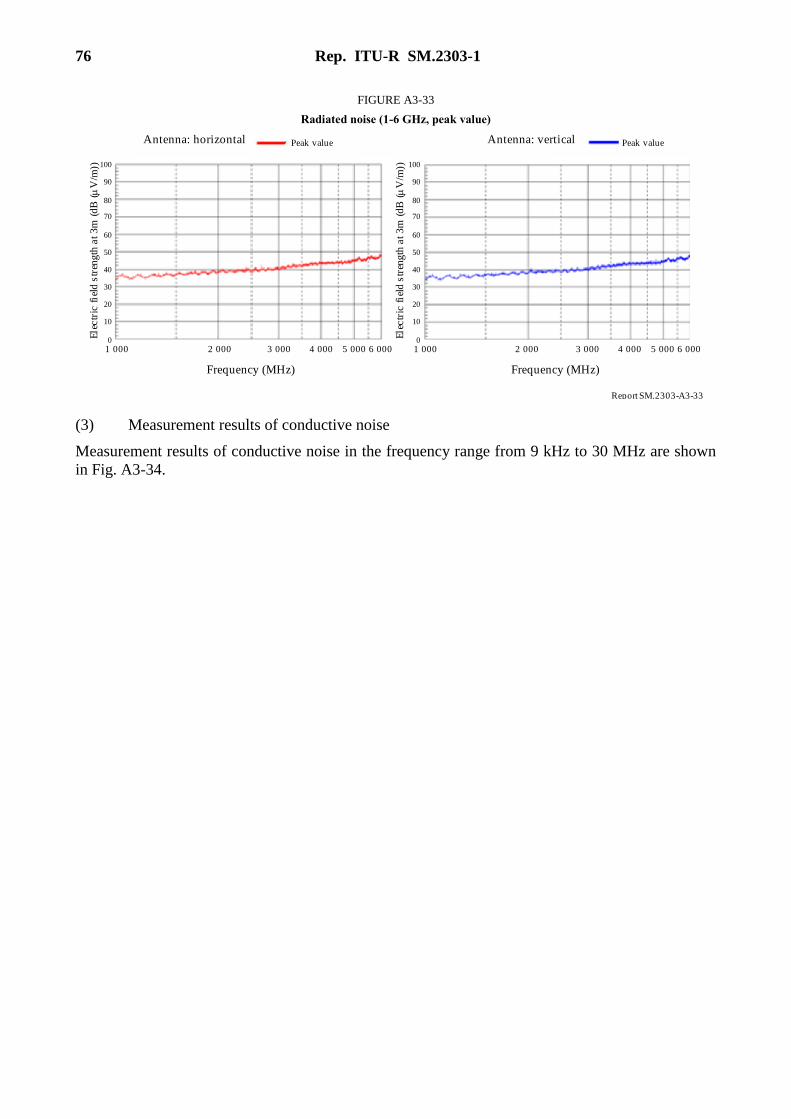
76 Rep. ITU-R SM.2303-1
FIGURE A3-33
Radiated noise (1-6 GHz, peak value)
R pe ort SM.2303-A3-33
Frequency (MHz)
1 000
Frequency (MHz)
0
20
50
70
Ele
ctr
ic f
ield
str
eng
th a
t 3m
(d
B (
V/m
))
90
10
30
60
80
100
Peak valueAntenna: horizontal
Ele
ctr
ic f
ield
str
eng
th a
t 3m
(d
B (
V/m
))
40
0
20
50
70
90
10
30
60
80
100
40
Peak valueAntenna: vertical
2 000 3 000 4 000 5 000 6 000 1 000 2 000 3 000 4 000 5 000 6 000
(3) Measurement results of conductive noise
Measurement results of conductive noise in the frequency range from 9 kHz to 30 MHz are shown
in Fig. A3-34.

Rep. ITU-R SM.2303-1 77
FIGURE A3-34
Conductive noise of test equipment (9 kHz - 30 MHz, peak and Quasi-peak value)
R pe ort SM.2303-A3-34
0.03
Frequency (MHz)
0.01 0.02
Frequency (MHz)
Peak valueN-phase
RF
I volt
ag
e (d
B
V)
0
20
50
70
90
10
40
60
80
100
Quasi-peak value
30
0.05 0.07 0.1 0.15
Peak valueL1-phaseQuasi-peak value
RF
I volt
ag
e (d
B
V)
0.030.01 0.02 0.05 0.07 0.1 0.150
20
50
70
90
10
40
60
80
100
30
RF
I vo
ltag
e (
dB
V
)
0
20
50
70
90
10
40
60
80
100
30
RF
I v
olta
ge
(dB
V
)
0
20
50
70
90
10
40
60
80
100
30
Peak valueN-phaseQuasi-peak value
Peak valueL1-phaseQuasi-peak value
2
Frequency (MHz)
0.2 0.5
Frequency (MHz)
3 5 10 200.3 0.7 1 7 20.2 0.5 3 5 10 200.3 0.7 1 730 30
a) 9 kHz - 150 kHz
b) 150 kHz - 30 MHz
______________