


Languages
Pages
Legal


8/12/2019 Poec Question Bank 1
http://slidepdf.com/reader/full/poec-question-bank-1 1/12
PRINCIPLES OF ELECTRONIC COMMUNICATION
UNIT – I
FUNDAMENTALS OF ANALOG COMMUNICATION
2 MARKS
1. Draw the basi b!"#s "$ "%%&'iati"' s(ste%s.
2. De$i'e %")&!ati"' a') )e%")&!ati"'.
Modulation is the process of changing the parameters of a relatively high frequency
carrier signal in proportion with the instantaneous value of the modulating signal.
*. Is %")&!ati"' %&st $"r "%%&'iati"' s(ste%+ E,-!ai' wh(+
Modulation is necessary for distance communication system. The main reasons for need
of modulation are,
• The antenna needed for transmitting signals should have size at least λ/4, where, λ
is the wavelength. The information signal, also known as aseand signal is of
low frequency !and therefore the wavelength is high". #f we need to transmit such
a signal directly, the size of the antenna will e very large and impossile to uild.$ence direct transmission is not practical.
• The radiated power y an antenna is inversely proportional to the square of the
wavelength. %o, if we use high frequency signals, the power radiated will e
increased.
• #f we transmit the aseand signals directly, the signals from different transmitters
will get mi&ed up and the information will e lost.
8/12/2019 Poec Question Bank 1
http://slidepdf.com/reader/full/poec-question-bank-1 2/12
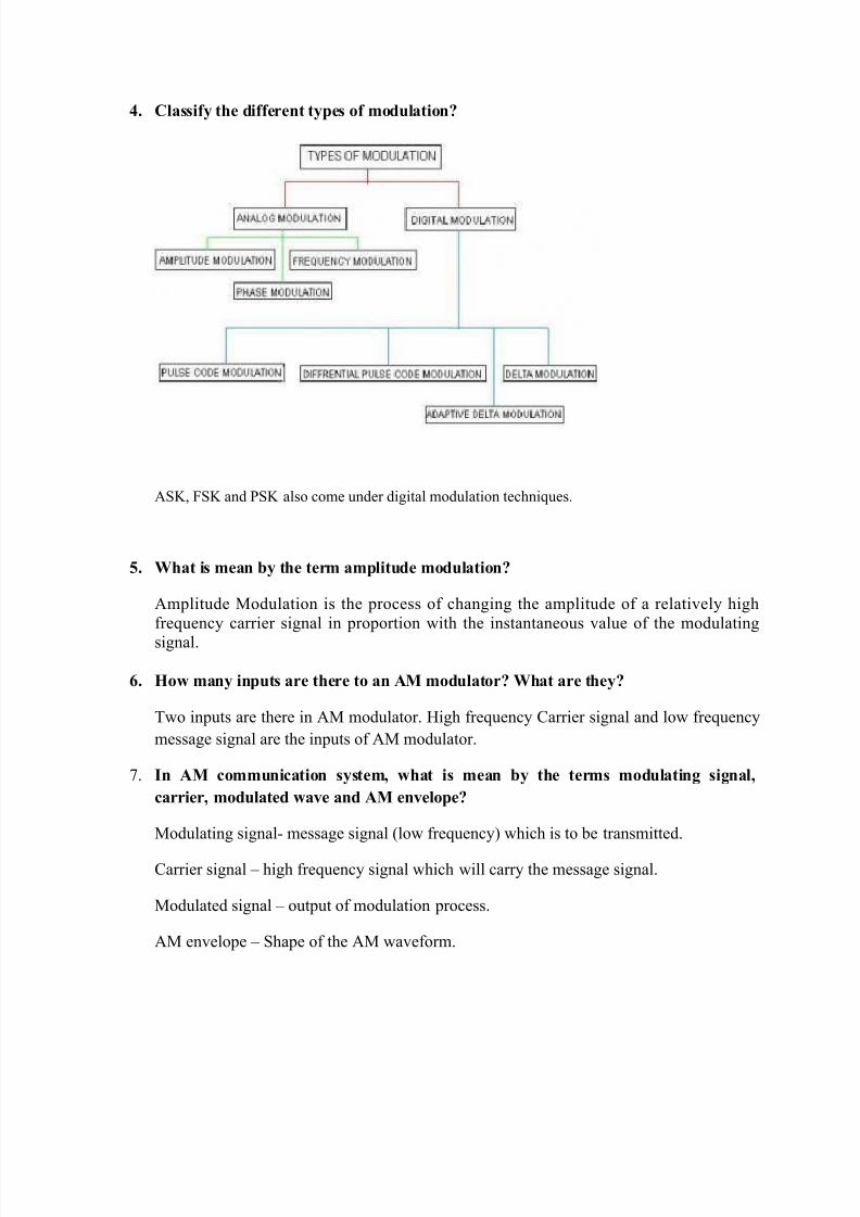
. C!assi$( the )i$$ere't t(-es "$ %")&!ati"'+
'%(, )%( and *%( also come under digital modulation techniques.
/. 0hat is %ea' b( the ter% a%-!it&)e %")&!ati"'+
'mplitude Modulation is the process of changing the amplitude of a relatively high
frequency carrier signal in proportion with the instantaneous value of the modulating
signal.
. "w %a'( i'-&ts are there t" a' AM %")&!at"r+ 0hat are the(+
Two inputs are there in 'M modulator. $igh frequency +arrier signal and low frequency
message signal are the inputs of 'M modulator.
. I' AM "%%&'iati"' s(ste%3 what is %ea' b( the ter%s %")&!ati'4 si4'a!3
arrier3 %")&!ate) wa5e a') AM e'5e!"-e+
Modulating signal- message signal !low frequency" which is to e transmitted.
+arrier signal high frequency signal which will carry the message signal.
Modulated signal output of modulation process.
'M envelope %hape of the 'M waveform.

8/12/2019 Poec Question Bank 1
http://slidepdf.com/reader/full/poec-question-bank-1 3/12
6. Draw the DS78FC 9AM: wa5e$"r%.
;. Draw the $re<&e'( s-etr&% "$ a' AM DS78FC wa5e.
1=. De$i'e &--er a') !"wer si)eba')s a') the &--er a') !"wer si)e $re<&e'ies "$ AM.
The signal components aove the carrier frequency constitute the &--er si)eba')
!US7", and those elow the carrier frequency constitute the !"wer si)eba') !LS7". The
frequencies within these ands are called as upper side frequencies and lower side
frequencies respectively.
. 0hat is the re!ati"'shi- betwee' the %")&!ati'4 si4'a! $re<&e'( a') the
ba')wi)th i' a "'5e'ti"'a! AM s(ste%+
The 0andwidth of an 'M 1%0)+ wave is equal to the difference etween the highest
upper side frequency and lowest lower side frequency. 0andwidth of the modulated
signal ecomes twice the frequency fm of modulating signal.
02 3 f c 5 f m!ma&"6 f c f m!ma&"6 3 7f m!ma&"

8/12/2019 Poec Question Bank 1
http://slidepdf.com/reader/full/poec-question-bank-1 4/12
12. De$i'e %")&!ati"' "e$$iie't 9%")&!ati"' i')e,: a') -ere't %")&!ati"'.
The ratio etween amplitude modulating signal and the carrier signal amplitude.
The modulation inde& !m" can vary etween 8 and .
9. 0hat is the si4'i$ia'e "$ -ere't %")&!ati"'+ 0hat ha--e's i$ -ere't
%")&!ati"' is ab"5e 1==>+
*ercent modulation gives the percentage change in the amplitude of the output wavewhen the carrier is acted on y a modulating signal. This provide the information aout,
to which e&tent the signal can e modulated. To avoid distortion, percent modulation
must not e&ceed 88 percent.
1. Draw the 5"!ta4e s-etr&% "$ DS78FC wa5e.
1/. 0rite the e<&ati"' $"r t"ta! -"wer "$ DS78FC wa5e$"r% a') )raw its -"wer
s-etr&%.
67
/
7
44
7
7
77
m P P
P m
P
P m
P m
P P
ct
cc
ccct
+=
+=
++=

8/12/2019 Poec Question Bank 1
http://slidepdf.com/reader/full/poec-question-bank-1 5/12
2here, *t is total power, *c is carrier power and m is modulation inde&.
1. 0hat are the )isa)5a'ta4es "$ AM DS78FC+
#n conventional 'M, carrier power constitutes two thirds or more of the total transmitted
power. This is a ma:or drawack ecause the carrier contains no information; thesideands contain the information.
1?. 0hat are i')iret FM a') i')iret PM+
2hen the frequency of a wave is changed, the phase will also change indirectly and vice
versa. This leads to indirect *M when )M is performed and indirect )M when *M is
performed.
16. 0hat ha--e's t" a%-!it&)e "$ the arrier wa5e i' $re<&e'( %")&!ati"'+
The +arrier amplitude remains the same after frequency modulation.
1;. Draw the FM wa5e$"r%.
2=. 0hat is $re<&e'( )e5iati"'+
The amount of change in carrier frequency produced y the modulating signal is known as
frequency deviation (frequency shift).
<f -frequency deviation
m fm E k f =∆

8/12/2019 Poec Question Bank 1
http://slidepdf.com/reader/full/poec-question-bank-1 6/12
( fm - deviation sensitivity
=m - peak amplitude of message signal
21. 0hat is %")&!ati"' i')e, a') -ere't %")&!ati"' "$ FM+
The ratio of the frequency deviation to the modulating frequency is defined as
modulation inde& of )M.
.
*ercent modulation in )M
22. De$i'e the ba')wi)th "$ FM 9ars"'@s r&!e:.
2here f m is message signal frequency and ∆f is frequency deviation.
2*. 0hih is %"re i%%&'e t" '"ise AM "r FM+ 0h(+
)M is more immune to noise than 'M. >oise in channel can produce change in
amplitude and phase of )M, ut not frequency directly.
2. 0hat is FM '"ise tria'4!e+
>oise triangle is a triangular noise distriution for )M. >oise triangle is the study of
effect of noise on the carrier signal of the )M wave. The noise triangle shows that noise
has a greater effect on the higher modulating frequencies than on the lower ones.
2/. 0hat is the -&r-"se "$ -re8e%-hasis a') )e8e%-hasis+
m
f f
f
cynalfrequenmessagesig
eviation frequencyd m
∆==
/88?mod@!ma&"
"!
f
f ulation
actual
∆
∆=
"!7 m f f BW +∆=

8/12/2019 Poec Question Bank 1
http://slidepdf.com/reader/full/poec-question-bank-1 7/12
' high pass filter that arti$iia!!( e%-hasie the high‐frequency components !amplitude"
of the message signal prior to the modulation is called as pre emphasis.
The de‐emphasis filter !low pass filter" restores the original signal y )ee%-hasii'4 the
high‐frequency components !amplitude".
2. Draw PM wa5e$"r%.
1 MARKS
. 1raw the lock diagram of communication systems and e&plain functions of each
lock.
7. 2hat is the principle of 'mplitude modulationA 1erive e&pression for the 'M
wave and draw its spectrum.
9. 1erive 'M modulated signal with relevant waveforms and notations and draw
the frequency spectrum of 'M and e&plain. *rove that the amplitude of carrier is
unaffected in modulation process.
4. 1erive the e&pression for total power in an 'M 1%0-)+ and draw the power
spectrum.

8/12/2019 Poec Question Bank 1
http://slidepdf.com/reader/full/poec-question-bank-1 8/12
B. =&plain the frequency modulation with neat diagram and derive the )M equation.
C. 2hat are the effects of noise on )MA =&plain a method to make )M wave
immune to noise.
. =&plain in detail aout pre-emphasis and de-emphasis.
D. =&plain the phase modulation with neat diagram and derive the *M equation.
E. +ompare 'M, )M and *M.
8/12/2019 Poec Question Bank 1
http://slidepdf.com/reader/full/poec-question-bank-1 9/12
UNIT – II
DIGITAL COMMUNICATION
2 MARKS
1. 0hat is )i4ita! %")&!ati"'+
#n digital modulation, an analog carrier signal is modulated y a digital it stream. 1igital
modulation methods can e considered as digital-to-analog conversion, and the
corresponding demodulation or detection as analog-to-digital conversion.
2. Gi5e the e,-ressi"' $"r Sha''"' !i%it $"r i'$"r%ati"' a-ait(.
The ma&imum rate at which data can e correctly communicated over a channel in
presence of noise and distortion is known as its channel capacity.
+ 3 0 log7 ! 5 %/>"
where 0 is the andwidth of the channel and %/> is the ratio of received signal power to
received noise power.
*. Gi5e the e,-ressi"' $"r art!e(@s !aw.
# α 0 & t
where #3 information capacity !its per second"
B3 andwidth !hertz"t = transmission time !seconds"
. Gi5e the N(<&ist $"r%&!ati"' $"r ha''e! a-ait(.
The minimum theoretical andwidth necessary to propagate a signal is called the
minimum >yquist andwidth or sometimes the minimum >yquist frequency. Thus,
$ b B 273 where f is the it rate in ps and 0 is the ideal >yquist andwidth.
/. De$i'e bit rate a') ba&).
#n digital modulation, the rate of change at the input to the modulator is called the it rate
!f " and has the unit of its per second !ps".The rate of change at the output of the modulator is called aud.
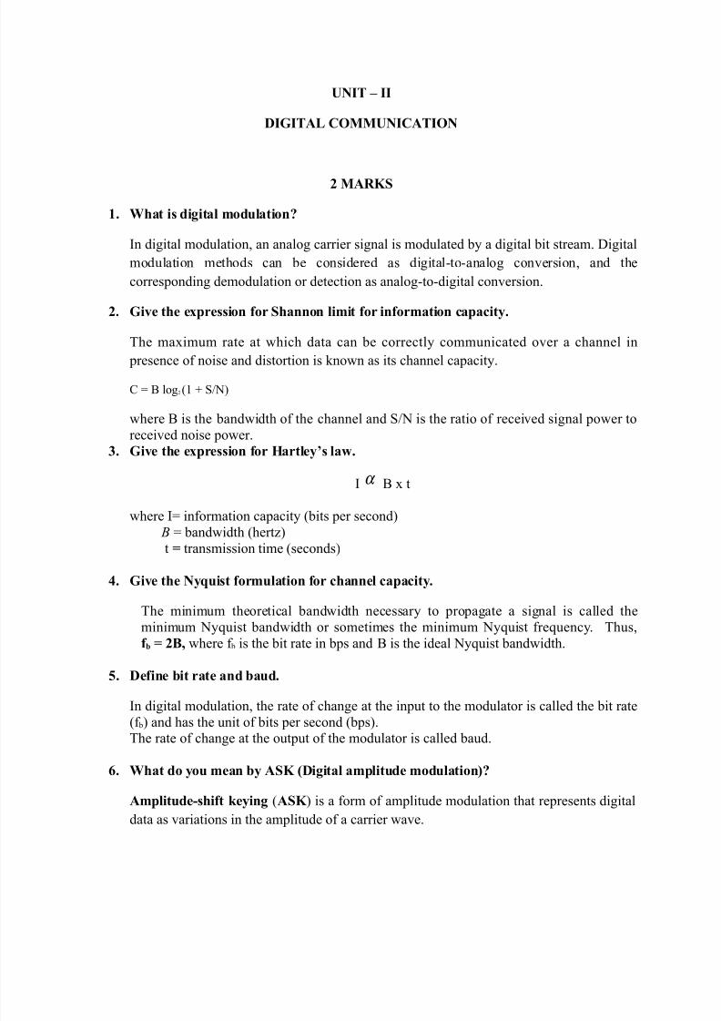
. 0hat )" ("& %ea' b( ASK 9Di4ita! a%-!it&)e %")&!ati"':+
A%-!it&)e8shi$t #e(i'4 !ASK " is a form of amplitude modulation that represents digital
data as variations in the amplitude of a carrier wave.
8/12/2019 Poec Question Bank 1
http://slidepdf.com/reader/full/poec-question-bank-1 10/12
?. 0h( ASK is a!!e) as "'8"$$ #e(i'4+
O'8"$$ #e(i'4 !OOK " the simplest form of amplitude-shift keying !'%(" modulation
that represents digital data as the presence or asence of a carrier wave.
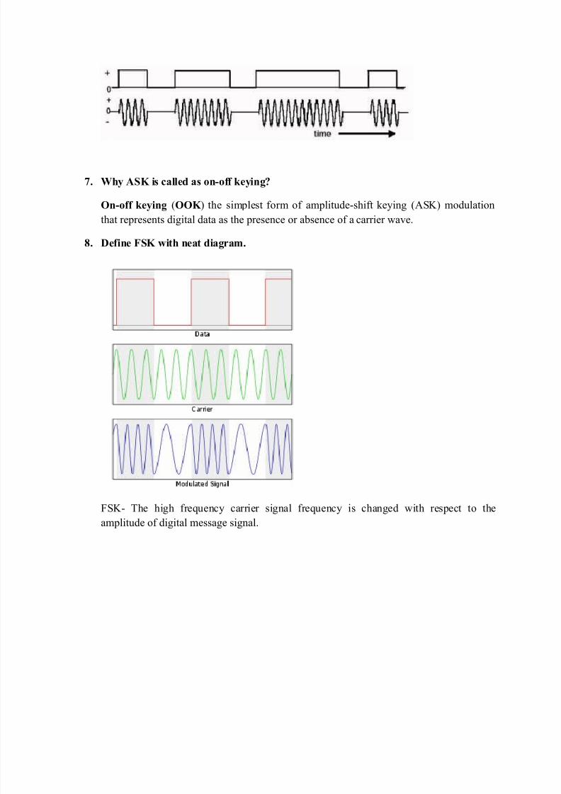
6. De$i'e FSK with 'eat )ia4ra%.
)%(- The high frequency carrier signal frequency is changed with respect to the
amplitude of digital message signal.

8/12/2019 Poec Question Bank 1
http://slidepdf.com/reader/full/poec-question-bank-1 11/12
;. De$i'e -ea# $re<&e'( )e5iati"' 9shi$t: $"r FSK.
The peak shift in the carrier frequency !<f" is proportional to the amplitude of the inary
input signal !vmt6", and the direction of the shift is determined y the polarity.
<f 3 Ff m f sF / 7
2here, <f = frequency deviation !hertz"
Ff m f sF 3 asolute difference etween the mark and space frequencies !hertz"
1=. Draw the b!"# )ia4ra% $"r FSK )e%")&!at"r.
)%( non coherent receiverG
)%( coherent receiverG

8/12/2019 Poec Question Bank 1
http://slidepdf.com/reader/full/poec-question-bank-1 12/12
1 MARKS
. 2rite short notes on information capacity, its, it rate, aud and M-ary encoding.
7. =&plain on off keying !HH(" or '%(.
9. =&plain 0)%( !transmitter and receiver" and also discuss aout the andwidth.
4. =&plain 0*%( !transmitter and receiver" and also discuss aout the andwidth.
B. =&plain I*%( transmitter and receiver.
C. 2ith the help of lock diagram e&plain the concepts of I'M.
. 2rite short notes on
a" %quaring loop
" +ostas loop
D. =&plain in detail aout the clock recovery.
Top Related