


Languages
Pages
Legal

MODELLING AND OPTIMIZATION OF DIRECT EXPANSION AIR CONDITIONING SYSTEM FOR COMMERCIAL BUILDING
ENERGY SAVING
V. Vakiloroaya*, J.G. Zhu, and Q.P. Ha
School of Electrical, Mechanical and Mechatronic Systems, University of Technology Sydney, Australia
* Corresponding author ([email protected])
ABSTRACT: This paper presents a comprehensive refinement of system modeling and optimization study of air-cooled
direct expansion (DX) refrigeration systems for commercial buildings to address the energy saving problem. An actual DX
rooftop package of a commercial building in the hot and dry climate condition is used for experimentation and data
collection. Both inputs and outputs are known and measured from the field monitoring. The optimal supply air temperature
and refrigerant flow rate are calculated based on the cooling load and ambient dry-bulb temperature profiles in one typical
week in the summer. Optimization is performed by using empirically-based models of the refrigeration system components
for energy savings. The results are promising as approximately 9% saving of the average power consumption can be
achieved subject to a predetermined comfort constraint on the ambient temperature. The proposed approach will make an
attractive contribution to residential and commercial building HVAC applications in moving towards green automation.
Keywords: Direct Expansion, Empirical Method, Energy Saving, Optimization
1. INTRODUCTION
The increasing consumption of energy in buildings on
heating, ventilating and air-conditioning (HVAC) systems
has initiated a great deal of research aiming at energy
savings. With the consolidation of the demand for human
comfort, HVAC systems have become an unavoidable asset,
accounting for almost 50% energy consumed in building
and around 10-20% of total energy consumption in
developed countries [1]. The direct expansion (DX) air
conditioning plant is one of the main HVAC systems for
different types of buildings. Its operation has a significant
effect to the overall building energy consumption. DX air
conditioning plants are simpler in configuration and more
cost-effective to maintain than central cooling ones using
chillers and cooling towers [2]. Therefore, these systems
have a wide application in small to medium size buildings.
The performance of DX systems can be improved by
determining the optimal decision variables of the system to
address the issues of energy savings and occupant comfort.
There are many studies on how the different control
strategies can reduce the HVAC energy consumption. Also
several studies have been developed for optimal control of
HVAC systems. Braun et al. [3] proposed a methodology
for determining the optimal control strategy for an HVAC
system in which they showed that the energy consumption
of a cooling plant can be represented in terms of the
controlled and uncontrolled variables by a quadratic cost
function. Their method allowed a rapid determination of
near-optimal control setting over a range of conditions.
Ahn and Mitchell [4] used this methodology for a central
cooling plant and illustrated the optimally-set temperatures
for supply air, chilled water and condenser water, to be
selected such that energy consumption is minimized under
a range of uncontrolled variables. Yao et al. [5] describes a
mathematically optimal operations of a large cooling
system based on an empirical model for chilled water
cooling systems and showed that 10% energy savings were
possible by applying the optimal model to a residential
cooling system. Huh and Brandemuehl [8] suggested a
method for optimization of a DX air conditioning system to
minimize energy with a special emphasis on the control of
humidity in commercial buildings. They showed that the
S7-2
233
most significant factors affecting the system operations are
the interaction between the compressor capacity control
and the supply air fan control.
The effect of different HVAC optimized control strategies
on energy consumption in an actual typical air conditioning
system was explored by Ghaddar et al [9]. The simulation
results demonstrated that varying the supply air
temperature and fresh air flow rate will result in a decrease
of 11% of the total operational energy cost. Yan et al. [10]
illustrated an adaptive optimal control model for building
cooling and heating sources. They showed that in this
model, a penalty function can be constructed to transform
the constrained optimization problem into an unconstrained
optimization problem, and that the energy consumption of
the cooling system can be reduced by 7% by applying
adaptive optimal control. Beghi and Cecchinato [11]
considered the problem of interaction between the
evaporator and electronic expansion valve to derive high-
performance adaptive control algorithms, but it is
necessary to consider the optimization of HVAC systems as
a whole. Yao and Chen [12] developed a global
optimization problem based on energy models of
components, but their formulation is for central air
conditioning systems.
In the context of energy optimization much research effort
has been paid to central chilled water cooling plants, there
are however a few published studies that have addressed
the effects of optimal control on overall energy
consumption by packaged rooftop DX air conditioning
systems. Apart from the practical validation of these
methods on real HVAC systems, especially on DX systems
are also important.
This paper discusses the modeling of the controlled and
uncontrolled variables of a DX cooling plant under
operation conditions with the aim to obtain explicit
expressions of decision variables to facilitate the derivation
of optimal parameters for direct expansion air conditioning
systems. Using this method, the overall energy
consumption through a given DX system can be modeled
by quadratic equations in terms of controlled and
uncontrolled variables by a suitable regression analysis of
experimental data. The controlled variables will then be
selected so that energy consumption is minimized under a
range of uncontrolled variables. In order to quantify and
determine the optimal control variables of the DX system,
a field test was conducted. A comparison of actual and
optimal power consumption was conducted for one week
in the summer time in a hot and dry climatic condition. The
results show that the on-line implementation of the
proposed decision variable set to determine the optimal
system references could save energy by 9%, while
maintaining the building comfort conditions.
2. MATHEMATICAL MODEL
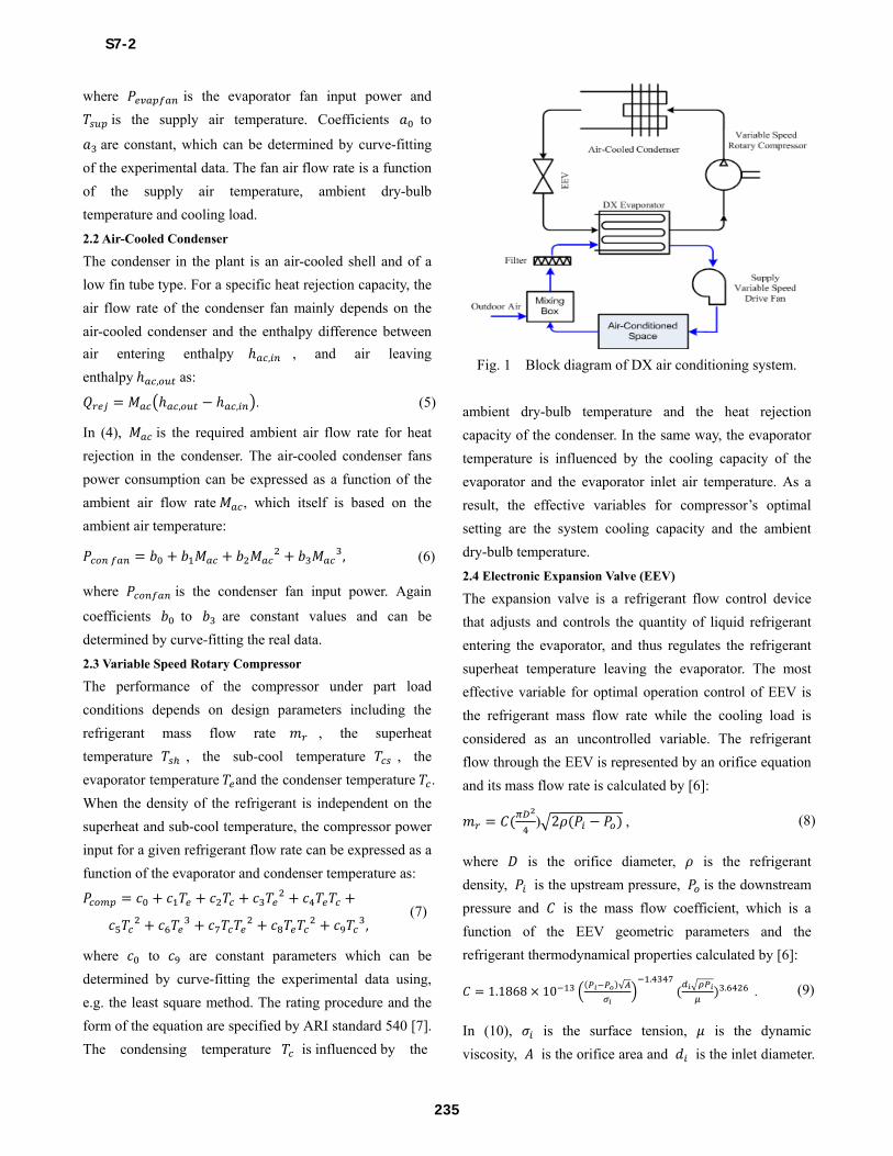
The schematic block diagram of a DX air conditioning
system is shown in Fig. 1. In the followings a combined
theoretical-empirical modeling approach will be developed
for these components.
2.1 DX Evaporator
The DX evaporator in the plant is of the rectangular finned
tube type and heat exchange between refrigerant and air is
assumed to be counter-flow. The cooling duty required for
the air cooling and dehumidifying process is calculated
using the difference between inlet and outlet air enthalpy. If
the inlet and outlet air enthalpy respectively are , and , , is the evaporator fan air flow rate, then the
required cooling duty , based on the principle of energy
conservation is given by:
, , , (1)
where the air enthalpy is evaluated by 1.005 0.001 2500 1.84 . (2)
In (2), is the ambient dry-bulb temperature and is
the moisture content of air evaluated by 2500 1.347 10102500 1.84 4.187 , (3)
where is the air wet-bulb temperature and is the
saturated moisture content.
The input power of the evaporator fan, which is adjusted
for part load operating conditions, can be expressed as a
function of the airflow rate of the fan as follows: , (4)
S7-2
234
where is the evaporator fan input power and
is the supply air temperature. Coefficients to are constant, which can be determined by curve-fitting
of the experimental data. The fan air flow rate is a function
of the supply air temperature, ambient dry-bulb
temperature and cooling load.
2.2 Air-Cooled Condenser
The condenser in the plant is an air-cooled shell and of a
low fin tube type. For a specific heat rejection capacity, the
air flow rate of the condenser fan mainly depends on the
air-cooled condenser and the enthalpy difference between
air entering enthalpy , , and air leaving
enthalpy , as: , , . (5)
In (4), is the required ambient air flow rate for heat
rejection in the condenser. The air-cooled condenser fans
power consumption can be expressed as a function of the
ambient air flow rate , which itself is based on the
ambient air temperature:
, (6)
where is the condenser fan input power. Again
coefficients to are constant values and can be
determined by curve-fitting the real data.
2.3 Variable Speed Rotary Compressor
The performance of the compressor under part load
conditions depends on design parameters including the
refrigerant mass flow rate , the superheat
temperature , the sub-cool temperature , the
evaporator temperature and the condenser temperature .
When the density of the refrigerant is independent on the
superheat and sub-cool temperature, the compressor power
input for a given refrigerant flow rate can be expressed as a
function of the evaporator and condenser temperature as:
, (7)
where to are constant parameters which can be
determined by curve-fitting the experimental data using,
e.g. the least square method. The rating procedure and the
form of the equation are specified by ARI standard 540 [7].
The condensing temperature is influenced by the
Fig. 1 Block diagram of DX air conditioning system.
ambient dry-bulb temperature and the heat rejection
capacity of the condenser. In the same way, the evaporator
temperature is influenced by the cooling capacity of the
evaporator and the evaporator inlet air temperature. As a
result, the effective variables for compressor’s optimal
setting are the system cooling capacity and the ambient
dry-bulb temperature.
2.4 Electronic Expansion Valve (EEV)
The expansion valve is a refrigerant flow control device
that adjusts and controls the quantity of liquid refrigerant
entering the evaporator, and thus regulates the refrigerant
superheat temperature leaving the evaporator. The most
effective variable for optimal operation control of EEV is
the refrigerant mass flow rate while the cooling load is
considered as an uncontrolled variable. The refrigerant
flow through the EEV is represented by an orifice equation
and its mass flow rate is calculated by [6]:
) 2 , (8)
where is the orifice diameter, is the refrigerant
density, is the upstream pressure, is the downstream
pressure and is the mass flow coefficient, which is a
function of the EEV geometric parameters and the
refrigerant thermodynamical properties calculated by [6]: 1.1868 10 √ . . . (9)
In (10), is the surface tension, is the dynamic
viscosity, is the orifice area and is the inlet diameter.
S7-2
235
3. PROBLEM FORMULATION
The optimization problem is formulated through the
determination of controlled variables, to minimize the
objective functions subject to constraints. Problem
variables for the direct expansion air conditioning system
under investigation are included supply air temperature,
refrigerant mass flow rate, total cooling load and ambient
dry-bulb temperature.
The objective function is to minimize of the overall power
consumption of the whole system with controlled variables
being and . The power consumption obtained
from the compressor, evaporator fan, and condenser fans is
given as: , Subject to constraints.
(10)
A quadratic form for this objective function for
optimization is proposed. This function represents the total
system's instantaneous power consumption , in terms
of the controlled and uncontrolled variables and consists of
fifteen coefficients that can be determined empirically
using real operation data and a regression technique.
.
(11)
To fit the function to the real test data, the regression can
be done using the MINITAB statistical software.
3.1 Optimizing Conditions
Once the empirical coefficients in (13) have been obtained,
the first-order derivatives with respect to the controlled
variables namely the supply air temperature and refrigerant
mass flow rate, are divided for the system optimizing
conditions. The following two equations must be solved in
order to calculate the optimal set-points:
0, 0 . (12)
The second order derivatives of the objective function with
respect to these controlled variables must be positive to
define a local minimum control.
3.2 Constraints
Equality and inequality constraints should be taken into
account during the optimization process. which are listed
as follows:
Constraint 1. The building cooling load must be less
than the cooling capacity of the DX plant: . (13)
Constraint 2. The interactions between the evaporator, air-
cooled condenser and the compressor formulate a
constraint as: . (14)
Constraint 3. The supply air temperature is restricted by 10° 20° . (15)
Constraint 4. The refrigerant mass flow rate through the
DX air conditioning system should be within its limitation:
, , . (16)
Constraint 5. The comfort ranges for the indoor air
temperature T and relative humidity RH during
occupied periods are given by: 22° 26° 40%° 60% . (17)
4. CASE STUDY
The proposed optimization process is applied on the
existing DX system. The air flow rate in an evaporator and
condenser is controlled by the variable speed drive (VSD)
fans. The refrigerant mass flow rate is controlled by the
electronic expansion valve.
4.1 Experimental Rig
In order to obtain an optimal set of control variables, a data
base with information about the system performance under
various operating conditions must first be gathered. For
this purpose, a real-world test data were collected in testing
conditions. High precision sensors/transducers were used
for measuring all operating variables. Manometers were
used for obtaining supply air flow rate. The temperature
sensor for supply air is of platinum resistance type
(accuracy: 0.1°C). The refrigerant mass flow rate passing
S7-2
236
through the EEV is measured by a Coriolis mass flow
meter (accuracy: 0.25°C). The ambient temperature was
measured by digital thermometer (precision: 0.8°C ).
Powers of components were measured by a digital ac/dc
power clamp multimeter (precision: 3.5%). Therefore a
total fifty-six points of system power consumption and
other variables were measured for each fifteen-minute
period. The building sensible and latent cooling load, were
calculated from monitoring data. After gathering the initial
set of real test variable values, the MINITAB statistical
software [14] was used to calculate the coefficients of the
quadratic cost function. The regression process explains the
coefficients in terms of variations in the actual overall
system energy consumption. The R-squared value of the
model was 0.93, indicating a good fit. These coefficients
for the described D.X rooftop package are: 84.27 3682 1049.33 13.13 24.694.07 0.02 0.028
0.16 4.63 0.070.03 2.19 0.03.
(18)
Therefore, the set of control function in terms of the
cooling load and ambient dry-bulb temperature are
obtained by solving the first-order controlled variable
derivatives:
, 0.0028 0.0059 0.0881, , 0.5002 0.2683 7.501. (19)
Since the sign of the second order derivatives of control
variables are positive, the control function defines a local
minimum control point: 20 0, 0.04 0 . (20)
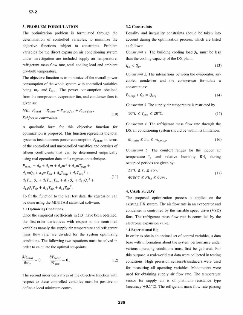
The control functions are plotted over the anticipated range
of cooling loads , shown in Fig. 2. This figure illustrates
that the optimal supply air temperature should be lowered
as cooling load increases while the refrigerant flow value
should be increased at a larger value of the cooling load. To
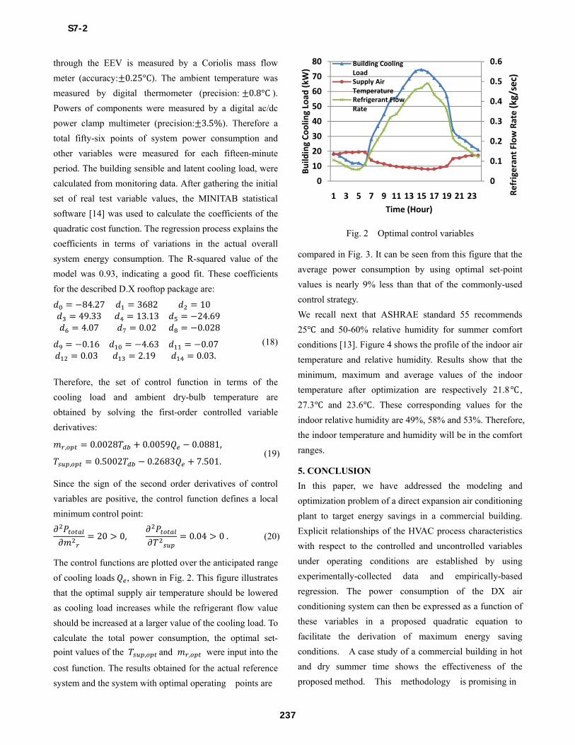
calculate the total power consumption, the optimal set-
point values of the , and , were input into the
cost function. The results obtained for the actual reference
system and the system with optimal operating points are
Fig. 2 Optimal control variables
compared in Fig. 3. It can be seen from this figure that the
average power consumption by using optimal set-point
values is nearly 9% less than that of the commonly-used
control strategy.
We recall next that ASHRAE standard 55 recommends
25 and 50-60% relative humidity for summer comfort
conditions [13]. Figure 4 shows the profile of the indoor air
temperature and relative humidity. Results show that the
minimum, maximum and average values of the indoor
temperature after optimization are respectively 21.8 ,
27.3 and 23.6 . These corresponding values for the
indoor relative humidity are 49%, 58% and 53%. Therefore,
the indoor temperature and humidity will be in the comfort
ranges.
5. CONCLUSION
In this paper, we have addressed the modeling and
optimization problem of a direct expansion air conditioning
plant to target energy savings in a commercial building.
Explicit relationships of the HVAC process characteristics
with respect to the controlled and uncontrolled variables
under operating conditions are established by using
experimentally-collected data and empirically-based
regression. The power consumption of the DX air
conditioning system can then be expressed as a function of
these variables in a proposed quadratic equation to
facilitate the derivation of maximum energy saving
conditions. A case study of a commercial building in hot
and dry summer time shows the effectiveness of the
proposed method. This methodology is promising in
0
0.1
0.2
0.3
0.4
0.5
0.6
0
10
20
30
40
50
60
70
80
1 3 5 7 9 11 13 15 17 19 21 23
Build
ing
Cool
ing
Load
(kW
)
Time (Hour)
Building Cooling LoadSupply Air TemperatureRefrigerant Flow Rate
Refr
iger
ant F
low
Rat
e (k
g/se
c)
S7-2
237
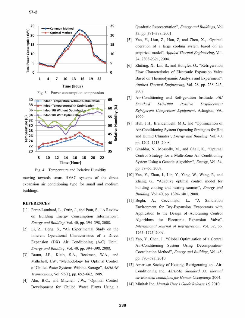
Fig. 3 Power consumption compression
Fig. 4 Temperature and Relative Humidity
moving towards smart HVAC systems of the direct
expansion air conditioning type for small and medium
buildings.
REFERENCES
[1] Perez-Lombard, L., Ortiz, J., and Pout, S., “A Review
on Building Energy Consumption Information”,
Energy and Building, Vol. 40, pp. 394–398, 2008.
[2] Li, Z., Deng, S., “An Experimental Study on the
Inherent Operational Characteristics of a Direct
Expansion (DX) Air Conditioning (A/C) Unit”,
Energy and Building, Vol. 40, pp. 394–398, 2008.
[3] Braun, J.E., Klein, S.A., Beckman, W.A., and
Mithchell, J.W., “Methodology for Optimal Control
of Chilled Water Systems Without Storage”, ASHRAE
Transactions, Vol. 95(1), pp. 652–662, 1989.
[4] Ahn, B.C., and Mitchell, J.W., “Optimal Control
Development for Chilled Water Plants Using a
Quadratic Representation”, Energy and Buildings, Vol.
33, pp. 371–378, 2001.
[5] Yao, Y., Lian, Z., Hou, Z, and Zhou, X., “Optimal
operation of a large cooling system based on an
empirical model”, Applied Thermal Engineering, Vol.
24, 2303-2321, 2004.
[6] Zhifang, X., Lin, S., and Hongfei, O., “Refrigeration
Flow Characteristics of Electronic Expansion Valve
Based on Thermodynamic Analysis and Experiment”,
Applied Thermal Engineering, Vol. 28, pp. 238–243,
2008.
[7] Air-Conditioning and Refrigeration Institude, ARI
Standard 540-1999 Positive Displacement
Refrigerant Compressor Equipment, Arlington, VA,
1999.
[8] Huh, J.H., Brandemuehl, M.J., and “Optimization of
Air-Conditioning System Operating Strategies for Hot
and Humid Climates”, Energy and Building, Vol. 40,
pp. 1202–1213, 2008.
[9] Ghaddar, N., Mossolly, M., and Ghali, K., “Optimal
Control Strategy for a Multi-Zone Air Conditioning
System Using a Genetic Algorithm”, Energy, Vol. 34,
pp. 58–66, 2009.
[10] Yan, Y., Zhou, J., Lin, Y., Yang, W., Wang, P., and
Zhang, G., “Adaptive optimal control model for
building cooling and heating sources”, Energy and
Building, Vol. 40, pp. 1394-1401, 2008.
[11] Beghi, A., Cecchinato, L., “A Simulation
Environment for Dry-Expansion Evaporators with
Application to the Design of Autotuning Control
Algorithms for Electronic Expansion Valve”,
International Journal of Refrigeration, Vol. 32, pp.
1765–1775, 2009.
[12] Yao, Y., Chen, J., “Global Optimization of a Central
Air-Conditioning System Using Decomposition-
Coordination Method”, Energy and Building, Vol. 45,
pp. 570–583, 2010.
[13] American Society of Heating, Refrigerating and Air-
Conditioning Inc, ASHRAE Standard 55: thermal
environment conditions for Human Occupancy, 2004.
[14] Minitab Inc, Minitab User’s Guide Release 16, 2010.
0
5
10
15
20
25
0
5
10
15
20
25
1 4 7 10 13 16 19 22
Tot
al P
ower
Con
sum
pti
on (
kW)
Time (hour)
Common MethodOptimal Method
35
40
45
50
55
60
65
2022242628303234363840
8 10 12 14 16 18 20 22
Tem
pera
ture
(C)
Time (Hour)
Indoor Temperature Without Optimization
Indoor TemperatureWith Optimization
Indoor RH Without Optimization
Indoor RH With OptimizationRe
lati
ve H
umid
ity
(%)
S7-2
238
Top Related