


Languages
Pages
Legal

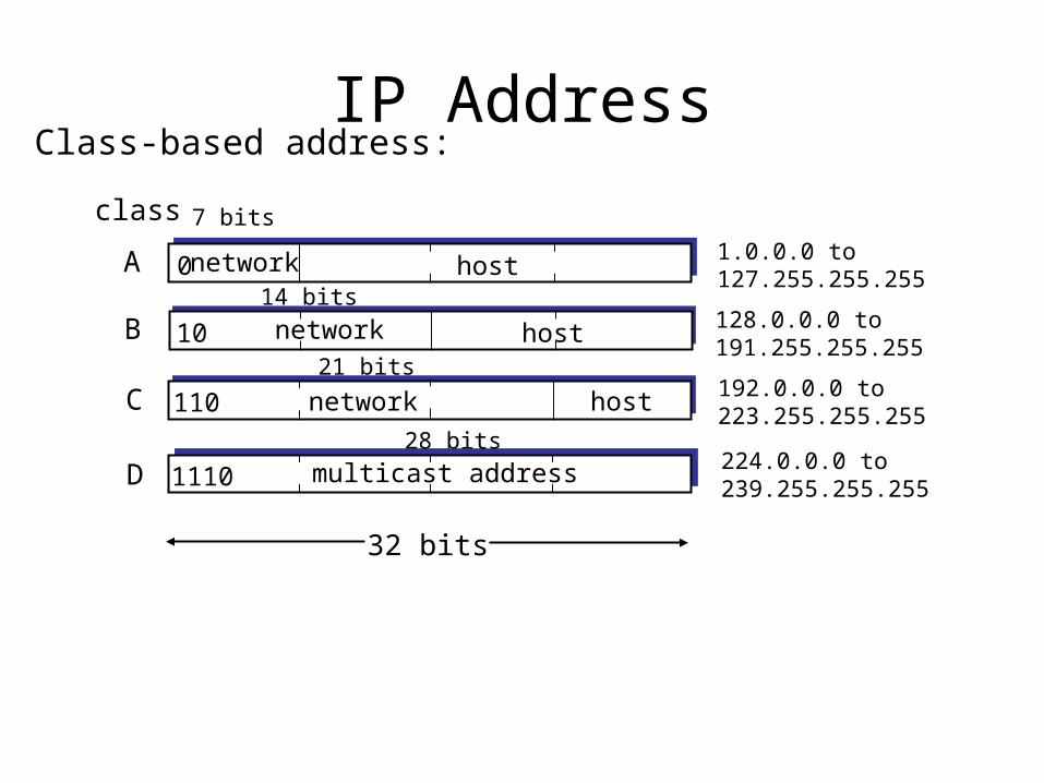
IP Address
0network host
10 network host
110 network host
1110 multicast address
A
B
C
D
class1.0.0.0 to127.255.255.255
128.0.0.0 to191.255.255.255
192.0.0.0 to223.255.255.255
224.0.0.0 to239.255.255.255
32 bits
7 bits
14 bits
21 bits
28 bits
Class-based address:
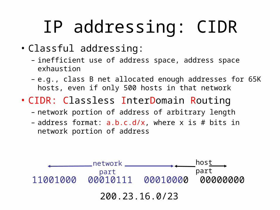
IP addressing: CIDR• Classful addressing:
– inefficient use of address space, address space exhaustion– e.g., class B net allocated enough addresses for 65K hosts,
even if only 500 hosts in that network
• CIDR: Classless InterDomain Routing– network portion of address of arbitrary length– address format: a.b.c.d/x, where x is # bits in network portion
of address
11001000 00010111 00010000 00000000
networkpart
hostpart
200.23.16.0/23
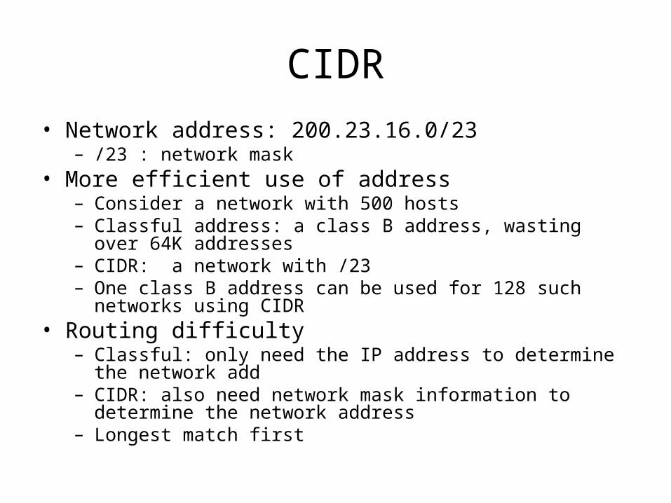
CIDR
• Network address: 200.23.16.0/23– /23 : network mask
• More efficient use of address– Consider a network with 500 hosts– Classful address: a class B address, wasting over 64K
addresses– CIDR: a network with /23– One class B address can be used for 128 such networks using
CIDR• Routing difficulty
– Classful: only need the IP address to determine the network add– CIDR: also need network mask information to determine the
network address– Longest match first
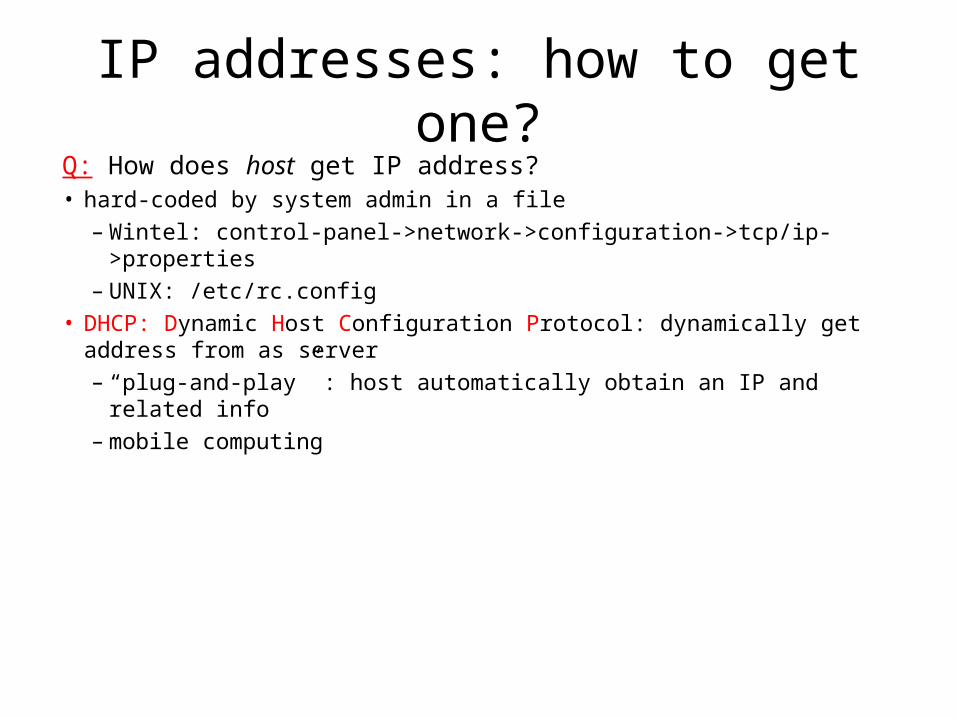
IP addresses: how to get one?Q: How does host get IP address?• hard-coded by system admin in a file
– Wintel: control-panel->network->configuration->tcp/ip->properties– UNIX: /etc/rc.config
• DHCP: Dynamic Host Configuration Protocol: dynamically get address from as server– “plug-and-play” : host automatically obtain an IP and related info– mobile computing
IP addresses: how to get one?
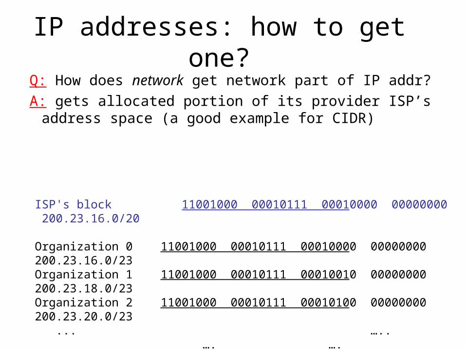
Q: How does network get network part of IP addr?
A: gets allocated portion of its provider ISP’s address space (a good example for CIDR)
ISP's block 11001000 00010111 00010000 00000000 200.23.16.0/20
Organization 0 11001000 00010111 00010000 00000000 200.23.16.0/23 Organization 1 11001000 00010111 00010010 00000000 200.23.18.0/23 Organization 2 11001000 00010111 00010100 00000000 200.23.20.0/23 ... ….. …. ….
Organization 7 11001000 00010111 00011110 00000000 200.23.30.0/23
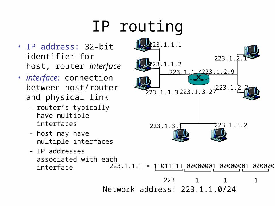
IP routing• IP address: 32-bit
identifier for host, router interface
• interface: connection between host/router and physical link– router’s typically have
multiple interfaces– host may have multiple
interfaces– IP addresses
associated with each interface
223.1.1.1
223.1.1.2
223.1.1.3
223.1.1.4 223.1.2.9
223.1.2.2
223.1.2.1
223.1.3.2223.1.3.1
223.1.3.27
223.1.1.1 = 11011111 00000001 00000001 00000001
223 1 11
Network address: 223.1.1.0/24

IP Routing• IP address:
– network part (high order bits) is used for routing
– host part (low order bits) not used for routing
223.1.1.1
223.1.1.2
223.1.1.3
223.1.1.4 223.1.2.9
223.1.2.2
223.1.2.1
223.1.3.2223.1.3.1
223.1.3.27
network consisting of 3 IP networks(for IP addresses starting with 223, first 24 bits are network address)
LAN
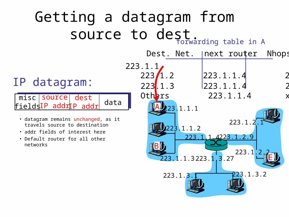
Getting a datagram from source to dest.
IP datagram:
223.1.1.1
223.1.1.2
223.1.1.3
223.1.1.4 223.1.2.9
223.1.2.2
223.1.2.1
223.1.3.2223.1.3.1
223.1.3.27
A
BE
miscfields
sourceIP addr
destIP addr data
• datagram remains unchanged, as it travels source to destination
• addr fields of interest here• Default router for all other networks
Dest. Net. next router Nhops
223.1.1 1223.1.2 223.1.1.4 2223.1.3 223.1.1.4 2Others 223.1.1.4 x
forwarding table in A

Getting a datagram from source to dest.
Starting at A, send IP datagram addressed to B:
• look up net. address of B in forwarding table
• find B is on same net. as A• link layer will send datagram directly
to B inside link-layer frame– B and A are directly connected
Dest. Net. next router Nhops
223.1.1 1223.1.2 223.1.1.4 2223.1.3 223.1.1.4 2
miscfields223.1.1.1223.1.1.3data
223.1.1.1
223.1.1.2
223.1.1.3
223.1.1.4 223.1.2.9
223.1.2.2
223.1.2.1
223.1.3.2223.1.3.1
223.1.3.27
A
BE
forwarding table in A
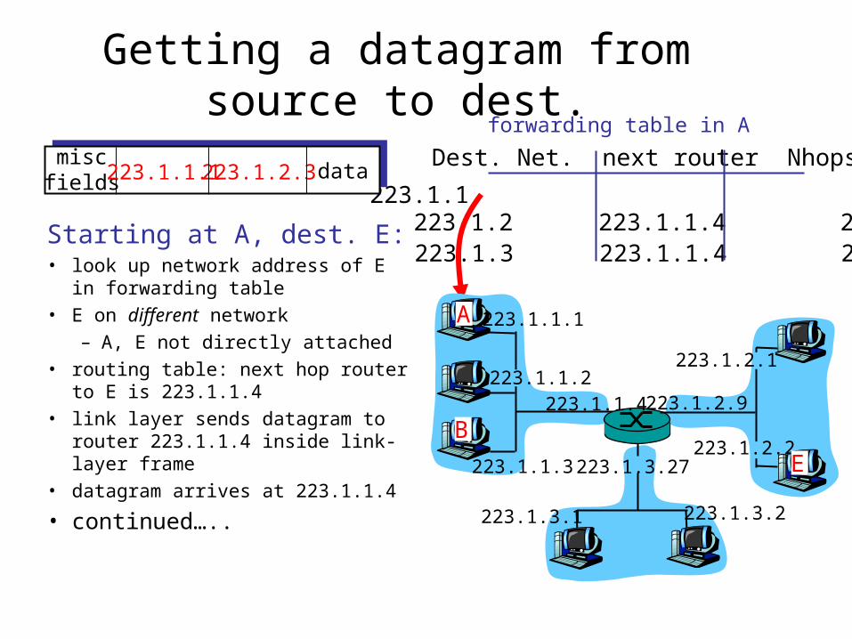
Getting a datagram from source to dest.
Dest. Net. next router Nhops
223.1.1 1223.1.2 223.1.1.4 2223.1.3 223.1.1.4 2Starting at A, dest. E:
• look up network address of E in forwarding table
• E on different network
– A, E not directly attached
• routing table: next hop router to E is 223.1.1.4
• link layer sends datagram to router 223.1.1.4 inside link-layer frame
• datagram arrives at 223.1.1.4
• continued…..
miscfields223.1.1.1223.1.2.3 data
223.1.1.1
223.1.1.2
223.1.1.3
223.1.1.4 223.1.2.9
223.1.2.2
223.1.2.1
223.1.3.2223.1.3.1
223.1.3.27
A
BE
forwarding table in A
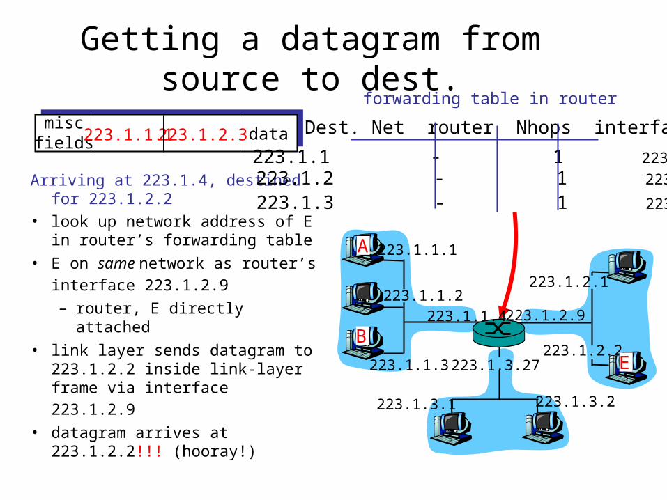
Getting a datagram from source to dest.
Arriving at 223.1.4, destined for 223.1.2.2
• look up network address of E in router’s forwarding table
• E on same network as router’s
interface 223.1.2.9 – router, E directly attached
• link layer sends datagram to 223.1.2.2 inside link-layer frame
via interface 223.1.2.9 • datagram arrives at 223.1.2.2!!!
(hooray!)
miscfields223.1.1.1223.1.2.3 data Dest. Net router Nhops interface
223.1.1 - 1 223.1.1.4 223.1.2 - 1 223.1.2.9
223.1.3 - 1 223.1.3.27
223.1.1.1
223.1.1.2
223.1.1.3
223.1.1.4 223.1.2.9
223.1.2.2
223.1.2.1
223.1.3.2223.1.3.1
223.1.3.27
A
BE
forwarding table in router

CIDR Routing
11001000 00010111 00010000 00000000
networkpart
hostpart
200.23.16.0/23
11001000 00010111 00000000 00000000
networkpart
hostpart
200.23.0.0/17
CIDR routing: longest match first
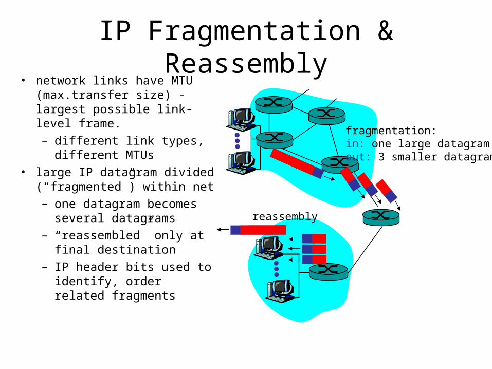
IP Fragmentation & Reassembly• network links have MTU
(max.transfer size) - largest possible link-level frame.– different link types,
different MTUs • large IP datagram divided
(“fragmented”) within net– one datagram becomes
several datagrams– “reassembled” only at
final destination– IP header bits used to
identify, order related fragments
fragmentation: in: one large datagramout: 3 smaller datagrams
reassembly

IP Fragmentation and Reassembly
ID=x
offset=0
fragflag=0
length=4000
ID=x
offset=0
fragflag=1
length=1500
ID=x
offset=1480
fragflag=1
length=1500
ID=x
offset=2960
fragflag=0
length=1040
One large datagram becomesseveral smaller datagrams
Example• 4000 byte
datagram• MTU = 1500 bytes

LAN Addresses and ARP
32-bit IP address: • network-layer address• used to get datagram to destination IP network (recall IP
network definition)
LAN (or MAC or physical or Ethernet) address: • used to get datagram from one interface to another
physically-connected interface (same network)• 48 bit MAC address (for most LANs)
burned in the adapter ROM

LAN Addresses and ARPEach adapter on LAN has unique LAN address

LAN Address (more)
• MAC address allocation administered by IEEE• manufacturer buys portion of MAC address space (to
assure uniqueness)• Analogy:
(a) MAC address: like Social Security Number
(b) IP address: like postal address• MAC flat address => portability
– can move LAN card from one LAN to another
• IP hierarchical address NOT portable– depends on IP network to which node is attached
Recall earlier routing discussion
223.1.1.1
223.1.1.2
223.1.1.3
223.1.1.4 223.1.2.9
223.1.2.2
223.1.2.1
223.1.3.2223.1.3.1
223.1.3.27
A
BE
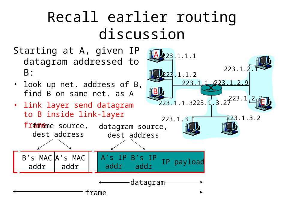
Starting at A, given IP datagram addressed to B:
• look up net. address of B, find B on same net. as A
• link layer send datagram to B
inside link-layer frame
B’s MACaddr
A’s MACaddr
A’s IPaddr
B’s IPaddr
IP payload
datagramframe
frame source,dest address
datagram source,dest address
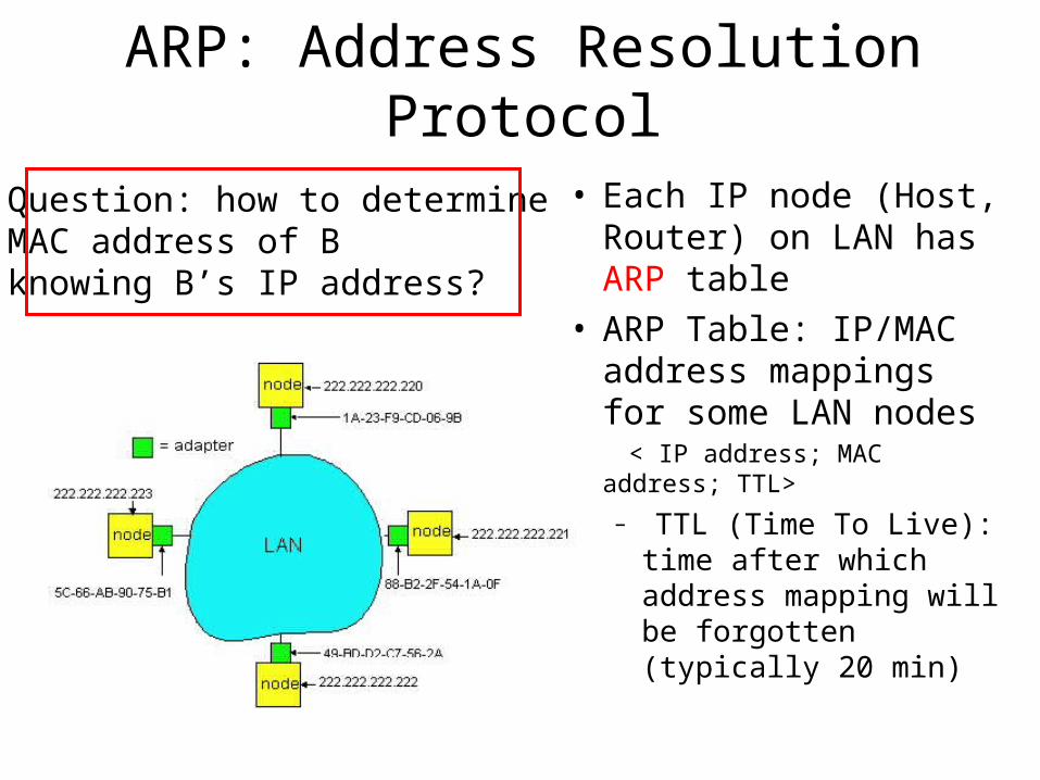
ARP: Address Resolution Protocol
• Each IP node (Host, Router) on LAN has ARP table
• ARP Table: IP/MAC address mappings for some LAN nodes
< IP address; MAC address; TTL>
– TTL (Time To Live): time after which address mapping will be forgotten (typically 20 min)
Question: how to determineMAC address of Bknowing B’s IP address?

ARP protocol
• A wants to send datagram to B, and A knows B’s IP address.
• Suppose B’s MAC address is not in A’s ARP table.
• A broadcasts ARP query packet, containing B's IP address – all machines on LAN
receive ARP query
• B receives ARP packet, replies to A with its (B's) MAC address– frame sent to A’s MAC
address (unicast)
• A caches (saves) IP-to-MAC address pair in its ARP table until information becomes old (times out) – soft state: information that
times out (goes away) unless refreshed
• ARP is “plug-and-play”:– nodes create their ARP
tables without intervention from net administrator
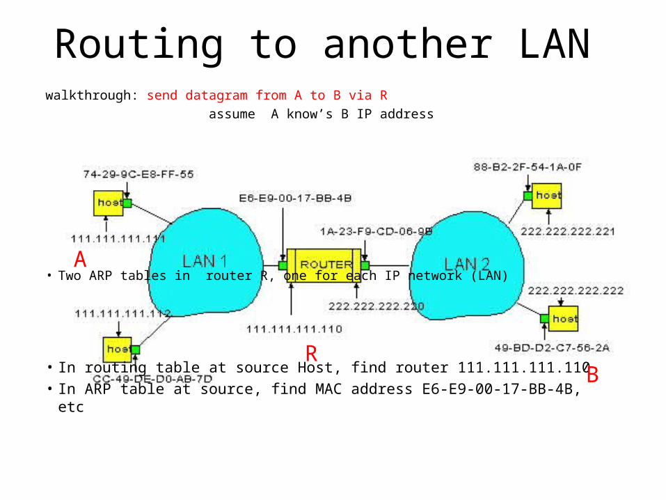
Routing to another LANwalkthrough: send datagram from A to B via R
assume A know’s B IP address
• Two ARP tables in router R, one for each IP network (LAN)
• In routing table at source Host, find router 111.111.111.110• In ARP table at source, find MAC address E6-E9-00-17-BB-4B, etc
A
RB
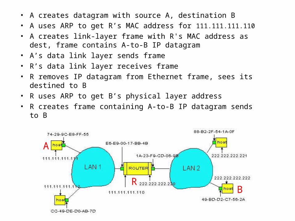
• A creates datagram with source A, destination B • A uses ARP to get R’s MAC address for 111.111.111.110
• A creates link-layer frame with R's MAC address as dest, frame contains A-to-B IP datagram
• A’s data link layer sends frame • R’s data link layer receives frame • R removes IP datagram from Ethernet frame, sees its destined
to B• R uses ARP to get B’s physical layer address • R creates frame containing A-to-B IP datagram sends to B
A
RB
Ethernet
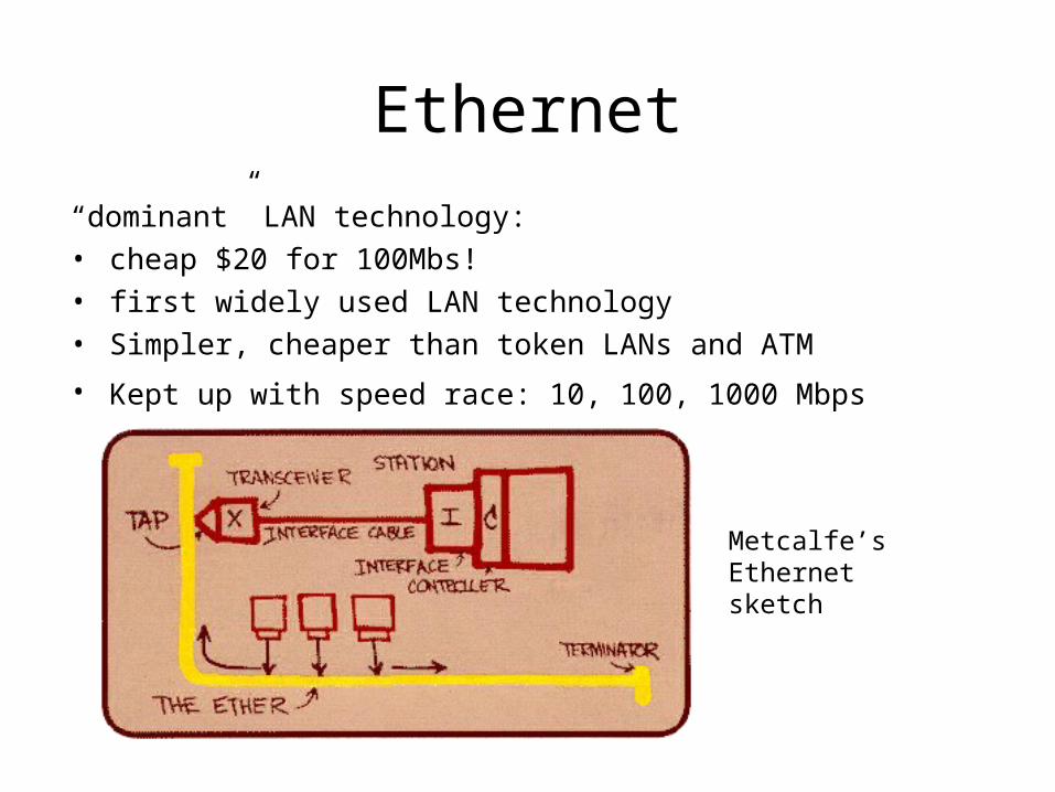
“dominant” LAN technology: • cheap $20 for 100Mbs!• first widely used LAN technology• Simpler, cheaper than token LANs and ATM
• Kept up with speed race: 10, 100, 1000 Mbps
Metcalfe’s Ethernetsketch
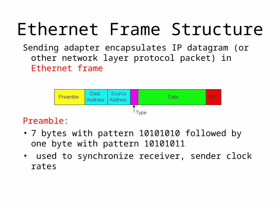
Ethernet Frame StructureSending adapter encapsulates IP datagram (or other
network layer protocol packet) in Ethernet frame
Preamble: • 7 bytes with pattern 10101010 followed by one
byte with pattern 10101011• used to synchronize receiver, sender clock rates

Ethernet Frame Structure (more)
• Addresses: 6 bytes– if adapter receives frame with matching destination address, or
with broadcast address (eg ARP packet), it passes data in frame to net-layer protocol
– otherwise, adapter discards frame
• Type: indicates the higher layer protocol, mostly IP but others may be supported such as Novell IPX and AppleTalk)
• CRC: checked at receiver, if error is detected, the frame is simply dropped
Top Related