


Languages
Pages
Legal

FISDR-ISR / F1902127X / 03 /2012 – updated 01/2016
APEX LOCATOR
User Manual

1 / 120
2 / 120
CONTENTS
English ....................................................................................... 4
Français ...................................................................................... 26
Deutsch ...................................................................................... 50
Español ...................................................................................... 72
Italiano ........................................................................................ 94
Electronic instructions for use
For additional languages, visit our website: www.dentsplymaillefer.com
Technical modifications on our products are not subject to notification. Photos of our devices are not contractual. Des modifications techniques peuvent être apportées à nos produits sans préavis. Les photos de nos dispositifs sont non contractuelles. Technische Änderungen an unseren Produkten können ohne Vorankündigung erfolgen. Fotos unserer Produkte sind unverbindlich. Las modificaciones técnicas de nuestros productos no son objeto de notificación. Las fotos de nuestros dispositivos no son contractuales. Modifiche tecniche dei prodotti non soggette a notifica. Le foto dei dispositivi sono solo indicativel.

3 / 120
4 / 120
User Manual
Table of contents
Introduction 5
1. Indications for use 5
2. Contraindications 6
3. Warnings 6
4. Precautions 7
5. Adverse Reactions 8
6. Step-by-Step Instructions 9
A. Contents 9
B. Connecting the AC plug adapter 9
C. Recharging the Battery 10
D. Replacement of the Rechargeable Battery 11
E. Getting Started 12
F. Search for the Apex 13
G. Sound Adjustment 15
H. Demo Mode 15
I. Automatic Shutdown 16
J. Maintenance of your ProPex® II 16
K. Warranty 17
L. Technical Specifications 17
M. Standard Symbols 18
7. Disinfection, cleaning and sterilization 19
8. Troubleshooting 22
9. Disposal of the Product 24
Appendix Electromagnetic compatibility (emc) ............................................... 116
5 / 120
FOR DENTAL USE ONLY
DIRECTIONS FOR USE
Introduction
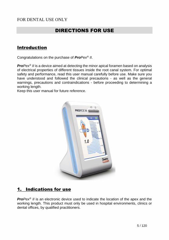
Congratulations on the purchase of ProPex® II. ProPex® II is a device aimed at detecting the minor apical foramen based on analysis of electrical properties of different tissues inside the root canal system. For optimal safety and performance, read this user manual carefully before use. Make sure you have understood and followed the clinical precautions - as well as the general warnings, precautions and contraindications - before proceeding to determining a working length. Keep this user manual for future reference.
1. Indications for use
ProPex® II is an electronic device used to indicate the location of the apex and the working length. This product must only be used in hospital environments, clinics or dental offices, by qualified practitioners.
6 / 120
2. Contraindications
The ProPex® II is not recommended for use:
in patients who have a pacemaker or other implanted electrical devices, or have been cautioned by their physicians against the use of small electric appliances such as shavers, hair dryers, etc,
in patients allergic to metals,
in children.
3. Warnings
The scale indication on the ProPex® II screen does not represent a distinct length or distance in mm or other linear units. It simply indicates the file progression towards the apex.
The following patient's related factors may prevent accurate readings:
- Blocked root canals,
- Teeth with large apices,
- Root fracture or perforation,
- Metal crowns or bridges, if they come into contact with the file or the lip clip.
Inaccurate or incorrect readings due to the environment are likely to occur in the following cases:
- Presence of portable or movable radio frequency transmitters in the surroundings.
- Film viewers or other Illumination devices which use an inverter may cause abnormal operation of the apex locator. Such devices should be turned off during use of the ProPex® II.
Electromagnetic interference could cause improper operation of the device. In such cases the device behavior may become abnormal or random. Usage of any devices emitting electromagnetic radiation, such as cellular phones, remote controls, transceivers, etc., should be prohibited in the vicinity of ProPex® II.
General safety warnings:
- In order to prevent infectious agent transfer it is highly recommended to use a rubber dam system during the endodontic procedure.
- Make sure that the lip clip, hook or fork does not come into contact with an electric power source such as an electrical socket. This could result in a severe electrical shock.
- Do not use ProPex® II in the presence of flammable substances.
Only use the original battery pack from your supplier.
Only use the original charger.
7 / 120
4. Precautions
Important notice
The use of apex locators alone without a preoperative and postoperative radiograph is not a recommended practice, since apex locators may not be able to work properly in all conditions.
It is mandatory to confirm radiographically the working length established using the apex locator.
It is important to follow the precautions below and pay close attention to any condition or situation that may influence the electrical conductivity during the procedure.
Inaccurate or incorrect readings are likely to occur in the following cases, all procedure related:
- Partially blocked canal.
- Size of the measuring file differing significantly from the canal diameter. Ideally, the selected file should be the thickest one capable of reaching the apex.
- Presence of liquids and/or tissue debris in the access cavity. Prior to the use of the device, the access cavity must be dried with a cotton pellet in order to prevent leaking current.
- Contact of the file or the lip clip with metallic dental structures. Be particularly careful with patients fitted with metal crowns or bridges.
- Contact of the file with another instrument.
- Very dry canal, for instance in the presence of restoration. In this case the canal must be moistened with an irrigation solution, or with GlydeTM file prep.
- Contact between the file and the gums (this may cause a false reading indicating that the apex has been reached).
- Use of an ultrasonic scaler with the counter electrode attached to the patient (electrical noise from the scaler could interfere with the apex localization).
- Use of the apex locator in conjunction with an electric scalpel.
- Use of a damaged lip clip, hook or fork.
For apex localization, concentrations of NaOCl higher than 5 % may result in reduced accuracy.
8 / 120
As a safety precaution in order to avoid over-instrumentation, it is recommended to proceed as follows: place the file onto an endodontic ruler at the point where the ProPex® II indicates ‘APEX’. Subtract a minimum of 0.5 mm from the measured file length.
Please also respect the following precautions:
- For your own safety, be aware of wearing personal protective equipment (gloves, glasses, mask).
- If the bar graph makes sudden large movements in the coronal part of the canal, slowly continue advancing the file toward the apex until the signal returns to normal.
- This ProPex® II unit must not be connected to or used in combination with any other apparatus or system. It must not be used as an integral component of any other apparatus or system. Using replacement parts or accessories not supplied by the original manufacturer or vender could adversely affect the EMC performance of the ProPex® II.
- The device must be used with the manufacturer's original accessories only.
- Unplug the device before replacing the battery.
- Never use batteries that are leaky, deformed, discolored or otherwise abnormal.
- In case of battery leakage, carefully dry the battery terminals and remove all of the leaked liquid. Then replace the battery with a new one.
- If you do not use the device for a long period of time, it is recommended to remove the battery from the device to prevent possible fluid leakage.
- Dispose of old batteries according to local codes and regulations.
- Accessories including lip clips, hooks or forks should be clean and without residue of chemical disinfectants or other medicinal solutions such as sodium hypochlorite or formalin.
- Do not expose ProPex® II to any liquid.
- ProPex® II must be stored in normal temperature (< 60°C) and humidity conditions.
5. Adverse Reactions
If the apex locator provides incorrect reading and there is no radiographic data (see "Important notice" in the “Precautions” section in chapter 4), the following adverse reactions may occur:
Incomplete root canal treatment,
Apex perforation.
9 / 120
6. Step-by-Step Instructions
A. Content
Check the content of the equipment before use:
- one ProPex® II apex locator - one switching charger with EU, UK, USA, AUS exchangeable plugs - one measurement cable - two lip clips - two connection hooks - two connection forks - one user manual
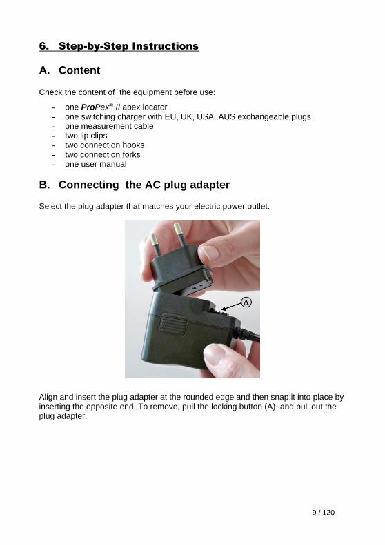
B. Connecting the AC plug adapter Select the plug adapter that matches your electric power outlet.
Align and insert the plug adapter at the rounded edge and then snap it into place by inserting the opposite end. To remove, pull the locking button (A) and pull out the plug adapter.
10 / 120
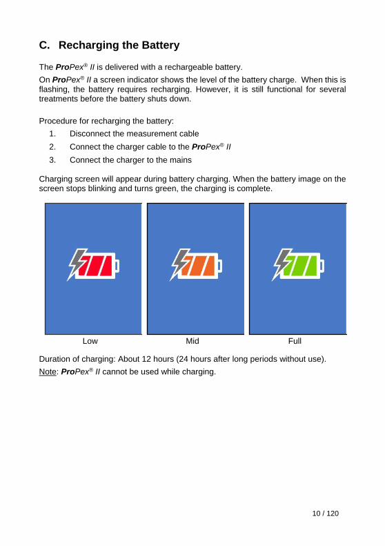
C. Recharging the Battery
The ProPex® II is delivered with a rechargeable battery.
On ProPex® II a screen indicator shows the level of the battery charge. When this is flashing, the battery requires recharging. However, it is still functional for several treatments before the battery shuts down.
Procedure for recharging the battery:
1. Disconnect the measurement cable
2. Connect the charger cable to the ProPex® II
3. Connect the charger to the mains Charging screen will appear during battery charging. When the battery image on the screen stops blinking and turns green, the charging is complete.
Low Mid Full
Duration of charging: About 12 hours (24 hours after long periods without use).
Note: ProPex® II cannot be used while charging.
11 / 120
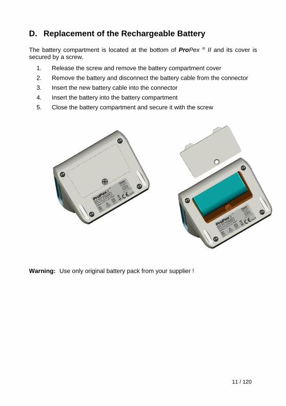
D. Replacement of the Rechargeable Battery
The battery compartment is located at the bottom of ProPex ® II and its cover is secured by a screw.
1. Release the screw and remove the battery compartment cover
2. Remove the battery and disconnect the battery cable from the connector
3. Insert the new battery cable into the connector
4. Insert the battery into the battery compartment
5. Close the battery compartment and secure it with the screw
Warning: Use only original battery pack from your supplier !
12 / 120
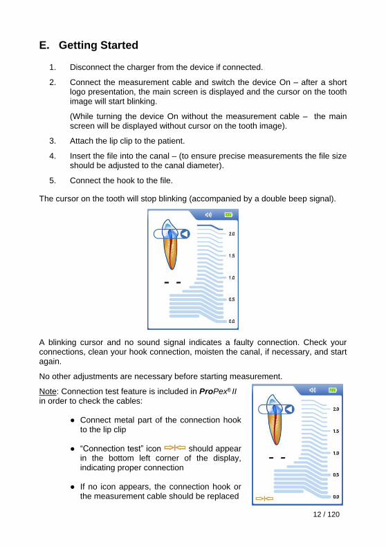
E. Getting Started
1. Disconnect the charger from the device if connected.
2. Connect the measurement cable and switch the device On – after a short logo presentation, the main screen is displayed and the cursor on the tooth image will start blinking.
(While turning the device On without the measurement cable – the main screen will be displayed without cursor on the tooth image).
3. Attach the lip clip to the patient.
4. Insert the file into the canal – (to ensure precise measurements the file size should be adjusted to the canal diameter).
5. Connect the hook to the file.
The cursor on the tooth will stop blinking (accompanied by a double beep signal).
A blinking cursor and no sound signal indicates a faulty connection. Check your connections, clean your hook connection, moisten the canal, if necessary, and start again.
No other adjustments are necessary before starting measurement.
Note: Connection test feature is included in ProPex® II
in order to check the cables:
● Connect metal part of the connection hook to the lip clip
● “Connection test” icon should appear
in the bottom left corner of the display, indicating proper connection
● If no icon appears, the connection hook or
the measurement cable should be replaced
13 / 120
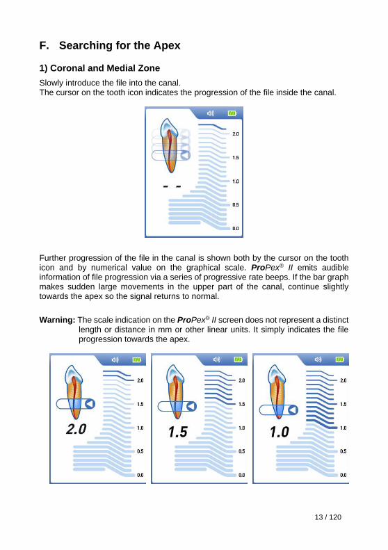
F. Searching for the Apex
1) Coronal and Medial Zone
Slowly introduce the file into the canal. The cursor on the tooth icon indicates the progression of the file inside the canal.
Further progression of the file in the canal is shown both by the cursor on the tooth icon and by numerical value on the graphical scale. ProPex® II emits audible information of file progression via a series of progressive rate beeps. If the bar graph makes sudden large movements in the upper part of the canal, continue slightly towards the apex so the signal returns to normal.
Warning: The scale indication on the ProPex® II screen does not represent a distinct
length or distance in mm or other linear units. It simply indicates the file progression towards the apex.
14 / 120
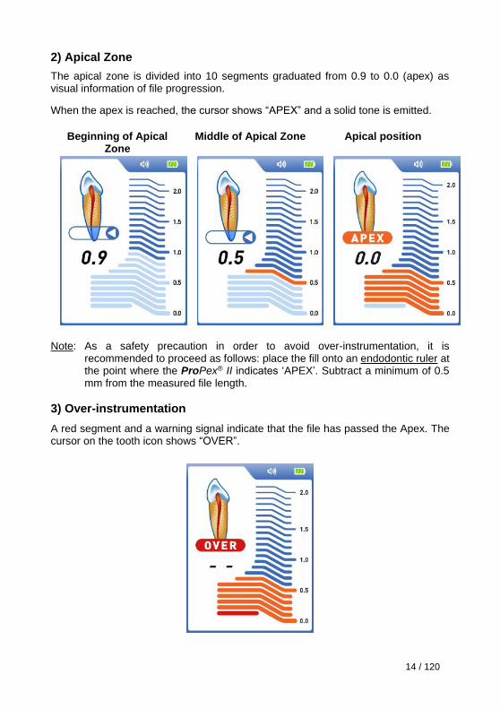
2) Apical Zone
The apical zone is divided into 10 segments graduated from 0.9 to 0.0 (apex) as visual information of file progression.
When the apex is reached, the cursor shows “APEX” and a solid tone is emitted.
Beginning of Apical
Zone Middle of Apical Zone
Apical position
Note: As a safety precaution in order to avoid over-instrumentation, it is
recommended to proceed as follows: place the fill onto an endodontic ruler at the point where the ProPex® II indicates ‘APEX’. Subtract a minimum of 0.5 mm from the measured file length.
3) Over-instrumentation
A red segment and a warning signal indicate that the file has passed the Apex. The cursor on the tooth icon shows “OVER”.
15 / 120
G. Sound Adjustment
ProPex® II is equipped with a sonic indicator which enables monitoring of the progression of the file within the canal.
This function, in conjunction with the display of progression, enables working "blind" while still monitoring the progression of the file.
The volume can be adjusted to one of four levels: mute, low, normal and high, by
successive presses on the volume key.
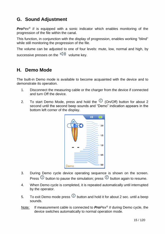
H. Demo Mode
The built-in Demo mode is available to become acquainted with the device and to demonstrate its operation.
1. Disconnect the measuring cable or the charger from the device if connected and turn Off the device.
2. To start Demo Mode, press and hold the (On/Off) button for about 2 second until the second beep sounds and “Demo” indication appears in the bottom left corner of the display.
3. During Demo cycle device operating sequence is shown on the screen.
Press button to pause the simulation; press button again to resume.
4. When Demo cycle is completed, it is repeated automatically until interrupted by the operator.
5. To exit Demo mode press button and hold it for about 2 sec. until a beep sounds.
Note: If measurement cable is connected to ProPex® II during Demo cycle, the device switches automatically to normal operation mode.
16 / 120
I. Automatic Shutdown
ProPex® II automatically shuts down after 5 minutes without use. It is advisable, however, to manually switch off equipment after measurement by simply pressing
the key (On/Off).
J. Maintenance of your ProPex® II
The device does not contain user serviceable parts. The service and repair should be provided by factory trained service personnel only.
After each use, all the objects that were in contact with infectious agents should be cleaned using towels impregnated with a disinfecting and detergent solution (a bactericidal, fungicidal and aldehyde free solution). Use of chemical agents may cause damage to the equipment. We recommend to use only a disinfecting solution which is approved for its efficacy (VAH/DGHM-listing, CE marking, FDA approval).
Other recommendations:
- Do not expose ProPex® II to any liquid. In particular, avoid spilling with chemical solutions used for treatment. These chemicals could cause damage, deform or discolor the device. Be especially careful to avoid spilling formalin cresol (FC) and sodium hypochlorite as they are quite aggressive. Wipe up any chemical spills immediately (some chemicals may leave discoloration and spots even if they are immediately wiped up).
- Handle the device carefully; do not drop, bump or expose the unit to any kind of impact or shock. Rough handling could cause significant damage.
- Do not drop anything on or bang the measuring cable plug after it has been inserted into the connector.
- ProPex® II must be stored in normal temperature (< 60°C) and humidity conditions.
Reprocessing procedure:
- The lip clip, the hook and the fork must be sterilized between treatments by autoclaving at 134°C.
- The measuring cable cannot be autoclaved.
See the section "Disinfection, cleaning and sterilization procedure for the ProPex® II accessories" for the detailed procedure.
17 / 120
K. Warranty
ProPex® II is warranted for 24 months from the date of purchase. The accessories (cables, battery etc.) are warranted for 6 months from the date of purchase. The warranty is valid for normal usage conditions. Any modification or accidental damage will render the warranty void.
L. Technical Specifications
ProPex® II complies to IEC60601-1 safety standard and the requirement of CE Marking of Conformity.
ProPex® II electronic apex locator belongs to the following category of medical devices:
- Internally powered equipment (2.4V NiMH rechargeable battery)
- Type BF applied parts
- Not suitable for use in the presence of flammable anesthetic mixtures with air, oxygen or nitrous oxide
- Continuous operation
- Ingress of liquids – not protected
- Environmental conditions during transportation: temperature: –20ºC to +60ºC (0 to 140ºF); relative humidity: 10% to 90%, non-condensing
Technical specifications Dimensions: 130 x 80 x 63 mm Weight: 360 gr. Type of screen: Color Graphic TFT Screen dimensions: 3.5 “ Supply: 2.4V NiMH rechargeable battery Switching charger: Input: 100-240 V AC ~ 50-60 Hz Output: 6V DC ± 5%, 1000 mA
18 / 120
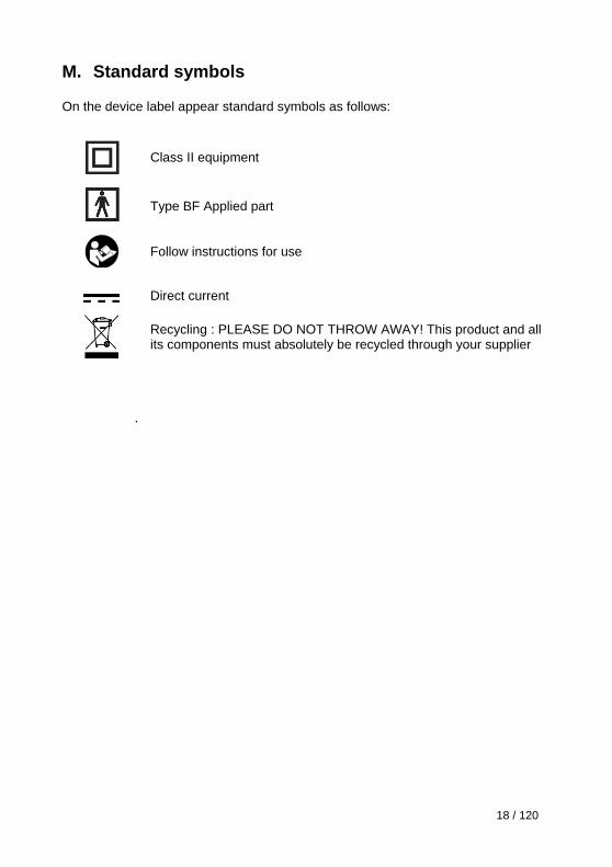
M. Standard symbols
On the device label appear standard symbols as follows:
Class II equipment
Type BF Applied part
Follow instructions for use
Direct current
Recycling : PLEASE DO NOT THROW AWAY! This product and all its components must absolutely be recycled through your supplier
.
19 / 120
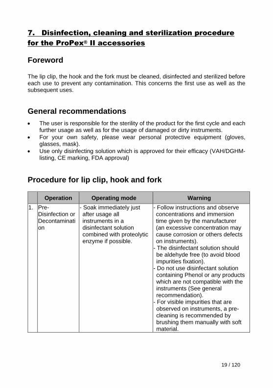
7. Disinfection, cleaning and sterilization procedure
for the ProPex® II accessories
Foreword
The lip clip, the hook and the fork must be cleaned, disinfected and sterilized before each use to prevent any contamination. This concerns the first use as well as the subsequent uses.
General recommendations
The user is responsible for the sterility of the product for the first cycle and each further usage as well as for the usage of damaged or dirty instruments.
For your own safety, please wear personal protective equipment (gloves, glasses, mask).
Use only disinfecting solution which is approved for their efficacy (VAH/DGHM-listing, CE marking, FDA approval)
Procedure for lip clip, hook and fork
Operation Operating mode Warning
1. Pre-Disinfection or Decontamination
- Soak immediately just after usage all instruments in a disinfectant solution combined with proteolytic enzyme if possible.
- Follow instructions and observe concentrations and immersion time given by the manufacturer (an excessive concentration may cause corrosion or others defects on instruments).
- The disinfectant solution should be aldehyde free (to avoid blood impurities fixation).
- Do not use disinfectant solution containing Phenol or any products which are not compatible with the instruments (See general recommendation).
- For visible impurities that are observed on instruments, a pre-cleaning is recommended by brushing them manually with soft material.
20 / 120
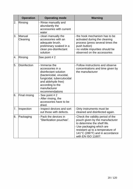
Operation Operating mode Warning
2. Rinsing - Rinse manually and abundantly the accessories with current water
3. Manual Cleaning
- clean manually the accessories with an adequate brush, preliminary soaked in a clean pre-disinfectant solution
- the hook mechanism has to be activated during the cleaning process (press several times the push button)
- no visible impurities should be observed on the accessories
4. Rinsing See point # 2
5. Disinfection - Immerse the accessories in a disinfectant solution (bactericidal, virucidal, fungicidal, tuberculocidal and aldehyde free) according to the manufacturer recommendations
- Follow instructions and observe concentrations and time given by the manufacturer
6. Final rinsing - See point # 2 - After rinsing, the accessories have to be dried.
7. Inspection - Inspect devices and sort out those with defects.
- Dirty instruments must be cleaned and disinfected again.
8. Packaging - Pack the devices in “Sterilization pouches”.
- Check the validity period of the pouch given by the manufacturer to determine the shelf life.
- Use packaging which are resistant up to a temperature of 141°C (286°F) and in accordance with EN ISO 11607.
21 / 120
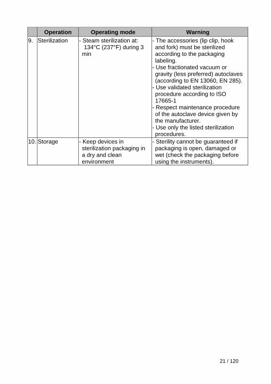
Operation Operating mode Warning
9. Sterilization
- Steam sterilization at: 134°C (237°F) during 3 min
- The accessories (lip clip, hook and fork) must be sterilized according to the packaging labeling.
- Use fractionated vacuum or gravity (less preferred) autoclaves (according to EN 13060, EN 285).
- Use validated sterilization procedure according to ISO 17665-1
- Respect maintenance procedure of the autoclave device given by the manufacturer.
- Use only the listed sterilization procedures.
10. Storage - Keep devices in sterilization packaging in a dry and clean environment
- Sterility cannot be guaranteed if packaging is open, damaged or wet (check the packaging before using the instruments).
22 / 120
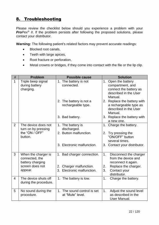
8. Troubleshooting
Please review the checklist below should you experience a problem with your ProPex® II. If the problem persists after following the proposed solutions, please contact your distributor. Warning: The following patient's related factors may prevent accurate readings:
Blocked root canals,
Teeth with large apices,
Root fracture or perforation,
Metal crowns or bridges, if they come into contact with the file or the lip clip.
# Problem Possible cause Solution
1 Triple beep signal during battery charging.
1. The battery is not connected.
1. Open the battery compartment, and connect the battery as described in the User Manual.
2. The battery is not a rechargeable type.
2. Replace the battery with a rechargeable type as described in the User Manual.
3. Bad battery.
3. Replace the battery with a new one.
2 The device does not turn on by pressing the “ON / OFF” button.
1. The battery is discharged.
1. Charge the battery.
2. Button malfunction. 2. Try pressing the “ON/OFF” button several times.
3. Electronic malfunction. 3. Contact your distributor.
3 When the charger is connected, the battery charging screen does not appear.
1. Bad charger connection. 1. Disconnect the charger from the device and reconnect it again.
2. Charger malfunction. 2. Replace the charger.
3. Electronic malfunction. 3. Contact your distributor.
4 The device shuts off during the procedure.
1. The battery is low. 1. Charge the battery.
5 No sound during the procedure.
1. The sound control is set at “Mute” level.
1. Adjust the sound level as described in the User Manual.
23 / 120
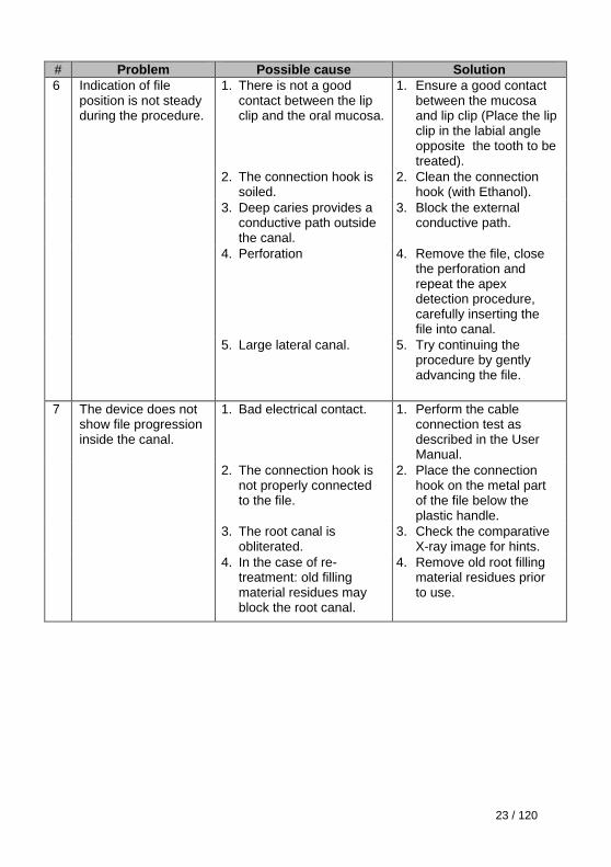
# Problem Possible cause Solution
6 Indication of file position is not steady during the procedure.
1. There is not a good contact between the lip clip and the oral mucosa.
1. Ensure a good contact between the mucosa and lip clip (Place the lip clip in the labial angle opposite the tooth to be treated).
2. The connection hook is soiled.
2. Clean the connection hook (with Ethanol).
3. Deep caries provides a conductive path outside the canal.
3. Block the external conductive path.
4. Perforation 4. Remove the file, close the perforation and repeat the apex detection procedure, carefully inserting the file into canal.
5. Large lateral canal. 5. Try continuing the procedure by gently advancing the file.
7 The device does not show file progression inside the canal.
1. Bad electrical contact. 1. Perform the cable connection test as described in the User Manual.
2. The connection hook is not properly connected to the file.
2. Place the connection hook on the metal part of the file below the plastic handle.
3. The root canal is obliterated.
3. Check the comparative X-ray image for hints.
4. In the case of re-treatment: old filling material residues may block the root canal.
4. Remove old root filling material residues prior to use.
24 / 120
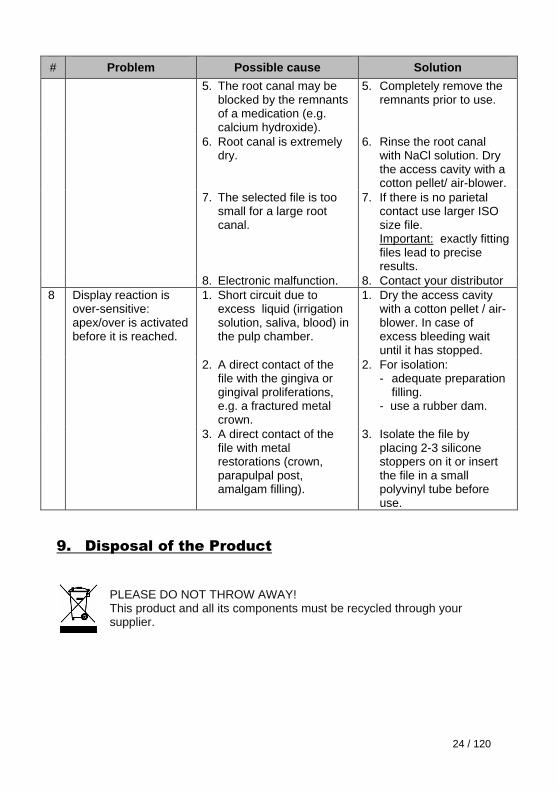
# Problem Possible cause Solution
5. The root canal may be blocked by the remnants of a medication (e.g. calcium hydroxide).
5. Completely remove the remnants prior to use.
6. Root canal is extremely dry.
6. Rinse the root canal with NaCl solution. Dry the access cavity with a cotton pellet/ air-blower.
7. The selected file is too small for a large root canal.
7. If there is no parietal contact use larger ISO size file.
Important: exactly fitting files lead to precise results.
8. Electronic malfunction. 8. Contact your distributor
8 Display reaction is over-sensitive: apex/over is activated before it is reached.
1. Short circuit due to excess liquid (irrigation solution, saliva, blood) in the pulp chamber.
1. Dry the access cavity with a cotton pellet / air-blower. In case of excess bleeding wait until it has stopped.
2. A direct contact of the file with the gingiva or gingival proliferations, e.g. a fractured metal crown.
2. For isolation: - adequate preparation
filling. - use a rubber dam.
3. A direct contact of the file with metal restorations (crown, parapulpal post, amalgam filling).
3. Isolate the file by placing 2-3 silicone stoppers on it or insert the file in a small polyvinyl tube before use.
9. Disposal of the Product
PLEASE DO NOT THROW AWAY! This product and all its components must be recycled through your supplier.
25 / 120
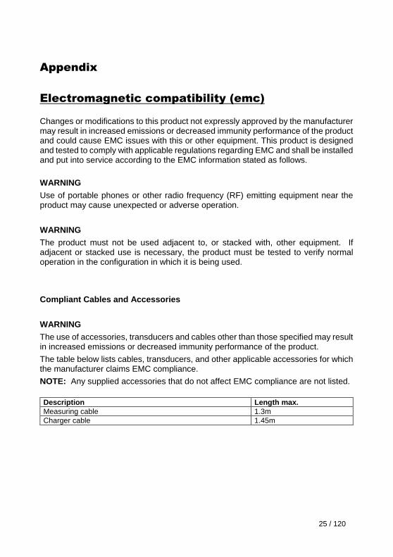
Appendix
Electromagnetic compatibility (emc)
Changes or modifications to this product not expressly approved by the manufacturer may result in increased emissions or decreased immunity performance of the product and could cause EMC issues with this or other equipment. This product is designed and tested to comply with applicable regulations regarding EMC and shall be installed and put into service according to the EMC information stated as follows.
WARNING
Use of portable phones or other radio frequency (RF) emitting equipment near the product may cause unexpected or adverse operation.
WARNING
The product must not be used adjacent to, or stacked with, other equipment. If adjacent or stacked use is necessary, the product must be tested to verify normal operation in the configuration in which it is being used.
Compliant Cables and Accessories
WARNING
The use of accessories, transducers and cables other than those specified may result in increased emissions or decreased immunity performance of the product.
The table below lists cables, transducers, and other applicable accessories for which the manufacturer claims EMC compliance.
NOTE: Any supplied accessories that do not affect EMC compliance are not listed.
Description Length max.
Measuring cable 1.3m
Charger cable 1.45m
26 / 120
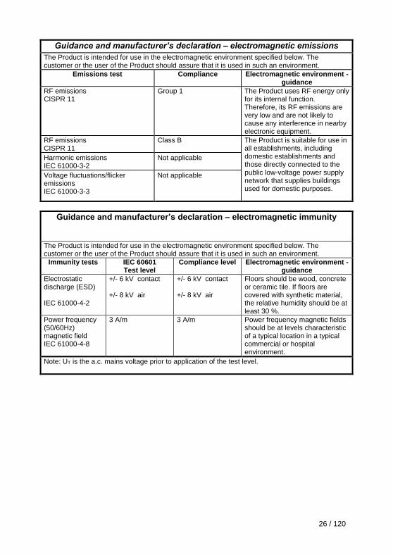
Guidance and manufacturer’s declaration – electromagnetic emissions
The Product is intended for use in the electromagnetic environment specified below. The customer or the user of the Product should assure that it is used in such an environment.
Emissions test Compliance Electromagnetic environment - guidance
RF emissions CISPR 11
Group 1 The Product uses RF energy only for its internal function. Therefore, its RF emissions are very low and are not likely to cause any interference in nearby electronic equipment.
RF emissions CISPR 11
Class B The Product is suitable for use in all establishments, including domestic establishments and those directly connected to the public low-voltage power supply network that supplies buildings used for domestic purposes.
Harmonic emissions IEC 61000-3-2
Not applicable
Voltage fluctuations/flicker emissions IEC 61000-3-3
Not applicable
Guidance and manufacturer’s declaration – electromagnetic immunity
The Product is intended for use in the electromagnetic environment specified below. The customer or the user of the Product should assure that it is used in such an environment.
Immunity tests IEC 60601 Test level
Compliance level Electromagnetic environment - guidance
Electrostatic discharge (ESD) IEC 61000-4-2
+/- 6 kV contact +/- 8 kV air
+/- 6 kV contact +/- 8 kV air
Floors should be wood, concrete or ceramic tile. If floors are covered with synthetic material, the relative humidity should be at least 30 %.
Power frequency (50/60Hz) magnetic field IEC 61000-4-8
3 A/m 3 A/m Power frequency magnetic fields should be at levels characteristic of a typical location in a typical commercial or hospital environment.
Note: UT is the a.c. mains voltage prior to application of the test level.
27 / 120
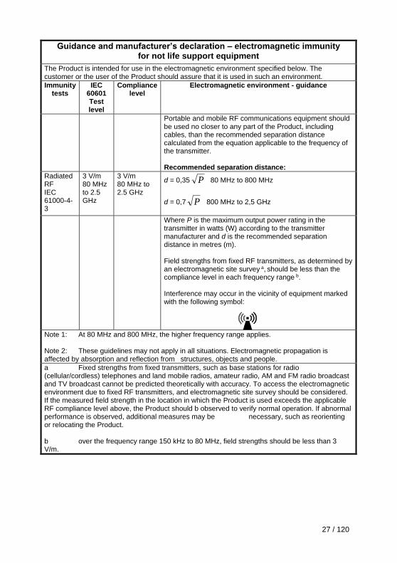
Guidance and manufacturer’s declaration – electromagnetic immunity for not life support equipment
The Product is intended for use in the electromagnetic environment specified below. The customer or the user of the Product should assure that it is used in such an environment.
Immunity tests
IEC 60601 Test level
Compliance level
Electromagnetic environment - guidance
Portable and mobile RF communications equipment should be used no closer to any part of the Product, including cables, than the recommended separation distance calculated from the equation applicable to the frequency of the transmitter. Recommended separation distance:
Radiated RF IEC 61000-4-3
3 V/m 80 MHz to 2.5 GHz
3 V/m 80 MHz to 2.5 GHz
d = 0,35 P 80 MHz to 800 MHz
d = 0,7 P 800 MHz to 2,5 GHz
Where P is the maximum output power rating in the transmitter in watts (W) according to the transmitter manufacturer and d is the recommended separation distance in metres (m). Field strengths from fixed RF transmitters, as determined by an electromagnetic site survey a, should be less than the compliance level in each frequency range b. Interference may occur in the vicinity of equipment marked with the following symbol:
Note 1: At 80 MHz and 800 MHz, the higher frequency range applies. Note 2: These guidelines may not apply in all situations. Electromagnetic propagation is affected by absorption and reflection from structures, objects and people.
a Fixed strengths from fixed transmitters, such as base stations for radio (cellular/cordless) telephones and land mobile radios, amateur radio, AM and FM radio broadcast and TV broadcast cannot be predicted theoretically with accuracy. To access the electromagnetic environment due to fixed RF transmitters, and electromagnetic site survey should be considered. If the measured field strength in the location in which the Product is used exceeds the applicable RF compliance level above, the Product should b observed to verify normal operation. If abnormal performance is observed, additional measures may be necessary, such as reorienting or relocating the Product. b over the frequency range 150 kHz to 80 MHz, field strengths should be less than 3 V/m.
28 / 120
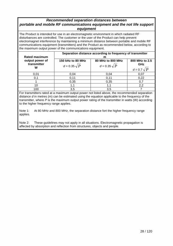
Recommended separation distances between portable and mobile RF communications equipment and the not life support
equipment
The Product is intended for use in an electromagnetic environment in which radiated RF disturbances are controlled. The customer or the user of the Product can help prevent electromagnet interference by maintaining a minimum distance between portable and mobile RF communications equipment (transmitters) and the Product as recommended below, according to the maximum output power of the communications equipment.
Rated maximum output power of
transmitter W
Separation distance according to frequency of transmitter m
150 kHz to 80 MHz
d = 0.35 P
80 MHz to 800 MHz
d = 0.35 P
800 MHz to 2.5 GHz
d = 0.7 P
0,01 0,04 0,04 0,07
0,1 0,11 0,11 0,22
1 0,35 0,35 0,7
10 1,1 1,1 2,2
100 3,5 3,5 7
For transmitters rated at a maximum output power not listed above, the recommended separation distance d in metres (m) can be estimated using the equation applicable to the frequency of the transmitter, where P is the maximum output power rating of the transmitter in watts (W) according to the higher frequency range applies. Note 1: At 80 MHz and 800 MHz, the separation distance fort the higher frequency range applies.
Note 2: These guidelines may not apply in all situations. Electromagnetic propagation is affected by absorption and reflection from structures, objects and people.

29 / 120
FISDR-ISR / F1902127X / 03 /2012 – updated 01/2016
www.dentsplymaillefer.com
Maillefer Instruments Holding Sàrl Chemin du Verger 3 CH – 1338 Ballaigues Switzerland
Top Related