


Languages
Pages
Legal

Page 1 of 14
IKO Insulations UK Appley Lane North Appley Bridge Wigan Lancashire WN6 9AB Tel: 01257 255771 Fax: 01257 252514 Agrément Certificate e-mail: [email protected] 15/5283 website: www.ikogroup.co.uk Product Sheet 1
IKO INSULATIONS IKO ENERTHERM ALU INSULATION BOARD FOR FLOORS
This Agrément Certificate Product Sheet(1) relates to IKO enertherm ALU Insulation Board for Floors, comprising a rigid polyisocyanurate (PIR) foam board with composite foil-facings, for use as insulation in ground-supported or suspended concrete or timber ground-floors, and also with exposed or semi-exposed intermediate concrete or timber floors, in new or existing domestic or similar buildings.
(1) Hereinafter referred to as ‘Certificate’.
CERTIFICATION INCLUDES:
• factors relating to compliance with Building Regulations where applicable
• factors relating to additional non-regulatory information where applicable
• independently verified technical specification • assessment criteria and technical investigations • design considerations • installation guidance • regular surveillance of production • formal three-yearly review.
KEY FACTORS ASSESSED
Thermal performance — the product has a declared thermal conductivity (D)* of 0.022 W·m–1·K–1 (see section 6).
Condensation risk — the product can contribute to limiting the risk of condensation (see section 7).
Floor loading — the product, when installed in accordance with this Certificate, can support a design loading for domestic applications (see section 9).
Durability — the product is durable, rot proof, water resistant and sufficiently stable to remain effective as an insulation for the life of the building (see section 11).
The BBA has awarded this Certificate to the company named above for the product described herein. This product has been assessed by the BBA as being fit for its intended use provided it is installed, used and maintained as set out in this Certificate.
On behalf of the British Board of Agrément
Date of First issue: 4 March 2016
John Albon – Head of Approvals Construction Products
Claire Curtis-Thomas Chief Executive
The BBA is a UKAS accredited certification body – Number 113. The schedule of the current scope of accreditation for product certification is available in pdf format via the UKAS link on the BBA website at www.bbacerts.co.uk Readers are advised to check the validity and latest issue number of this Agrément Certificate by either referring to the BBA website or contacting the BBA direct.
British Board of Agrément Bucknalls Lane Watford Herts WD25 9BA
©2016
tel: 01923 665300 fax: 01923 665301
[email protected] www.bbacerts.co.uk

Page 2 of 14
Regulations In the opinion of the BBA, IKO enertherm ALU Insulation Board for Floors, if installed, used and maintained in accordance with this Certificate, can satisfy or contribute to satisfying the relevant requirements of the following Building Regulations (the presence of a UK map indicates that the subject is related to the Building Regulations in the region or regions of the UK depicted):
The Building Regulations 2010 (England and Wales) (as amended)
Requirement: A1 Loading Comment: The product can contribute to satisfying this Requirement. See section 9.2 of this
Certificate. Requirement: C2(c) Resistance to moisture Comment: The product can contribute to satisfying this Requirement. See sections 7.1 and 7.4 of
this Certificate. Requirement: L1(a)(i) Conservation of fuel and power Comment: The product can contribute to satisfying this Requirement. See section 6 of this
Certificate. Regulation: 7 Materials and workmanship Comment: The product is acceptable. See section 11 and the Installation part of this Certificate. Regulation: Regulation: Regulation: Regulation:
26 26A 26A 26B
CO2 emission rates for new buildings Fabric energy efficiency rates for new dwellings (applicable to England only) Primary energy consumption rates for new buildings (applicable to Wales only) Fabric performance values for new dwellings (applicable to Wales only)
Comment: The product can contribute to satisfying these Regulations. See section 6 of this Certificate.
The Building (Scotland) Regulations 2004 (as amended)
Regulation: 8(1) Durability, workmanship and fitness of materials Comment: The product is acceptable. See section 11 and the Installation part of this Certificate. Regulation: 9 Building standards applicable to construction Standard: 1.1(b) Structure Comment: The product can contribute to satisfying this Standard, with reference to clause 1.1.1(1)(2).
See section 9.2 of this Certificate. Standard: 3.15 Condensation Comment: The product can contribute to satisfying this Standard, with reference to clauses
3.15.1(1)(2), 3.15.4(1)(2) and 3.15.5(1)(2). See sections 7.1 and 7.5 of this Certificate. Standard: 6.1(b) Carbon dioxide emissions Standard: 6.2 Building insulation envelope Comment: The product can contribute to satisfying these Standards, with reference to clauses, or
parts of, 6.1.1(1), 6.1.6(1), 6.2.1(1)(2), 6.2.3(1)(2), 6.2.4(1)(2), 6.2.5(1)(2), 6.2.6(1)(2), 6.2.7(1), 6.2.8(2), 6.2.9(1)(2), 6.2.10(1), 6.2.11(1)(2), 6.2.12(2) and 6.2.13(1)(2). See section 6 of this Certificate.
Standard: 7.1(a)(b) Statement of sustainability Comment: The product can contribute to satisfying the relevant requirements of Regulation 9,
Standards 1 to 6, and therefore will contribute to a construction meeting a bronze level of sustainability as defined in this Standard. In addition, the product can contribute to a construction meeting a higher level of sustainability as defined in this Standard, with reference to clauses 7.1.4(1)(2) [Aspects 1(1)(2) and 2(1)], 7.1.6(1) [Aspects 1(1)(2) and 2(1)] and 7.1.7(1)(2) [Aspect 1(1)(2)]. See section 6 of this Certificate.

Page 3 of 14
Regulation: 12 Building standards applicable to conversions Comment: Comments made in relation to this product under Regulation 9, Standards 1 to 6, also
apply to this Regulation, with reference to clause 0.12.1(1)(2) and Schedule 6(1)(2). (1) Technical Handbook (Domestic)
(2) Technical Handbook (Non-Domestic).
The Building Regulations (Northern Ireland) 2012 (as amended)
Regulation: 23 Fitness of materials and workmanship Comment: The product is acceptable. See section 11 and the Installation part of this Certificate. Regulation: 29 Condensation Comment: The product can contribute to satisfying this Regulation. See section 7.1 of this
Certificate. Regulation: 30 Stability Comment: The product can contribute to satisfying this Regulation. See section 9.2 of this
Certificate. Regulation: 39(a)(i) Conservation measures Regulation: 40(2) Target carbon dioxide emission rate Comment: The product can contribute to satisfying these Regulations. See section 6 of this
Certificate.
Construction (Design and Management) Regulations 2015 Construction (Design and Management) Regulations (Northern Ireland) 2007 Information in this Certificate may assist the client, Principal Designer/CDM co-ordinator, designer and contractors to address their obligations under these Regulations. See section: 3 Delivery and site handling (3.4) of this Certificate.
Additional Information
NHBC Standards 2016 NHBC accepts the use of IKO enertherm ALU Insulation Board for Floors provided it is installed, used and maintained in accordance with this Certificate, in relation to NHBC Standards, Chapters 5.1 Substructure and ground bearing floors and 5.2 Suspended ground floors.
CE marking The Certificate holder has taken the responsibility of CE marking the product in accordance with harmonised European Standard BS EN 13165 : 2012. An asterisk (*) appearing in this Certificate indicates that data shown is given in the manufacturer’s Declaration of Performance.
Technical Specification
1 Description IKO enertherm ALU Insulation Board for Floors comprises a rigid polyisocyanurate (PIR) board with composite foil-facings, with the nominal characteristics given in Table 1.

Page 4 of 14
Table 1 Nominal characteristics
Size (mm) 1200 x 600 1200 x 1000 1200 x 2400
Thickness (mm) 30, 40, 50, 60, 70, 75, 80, 90, 100, 110, 120 and 140
Edge detail Plain square edge
Minimum compressive stress at 10% deformation (kPa)* 175
Foil-facings Printed composite foil-facing both sides
2 Manufacture 2.1 IKO enertherm ALU Insulation Board for Floors is manufactured by blending together polyol and MDI in a continuous foaming process aided by a blowing agent, and sandwiched between two composite foil-facings. After formation, the boards are left to cure and are cut to size. 2.2 As part of the assessment and ongoing surveillance of product quality, the BBA has: ● agreed with the manufacturer the quality control procedures and product testing to be undertaken ● assessed and agreed the quality control operated over batches of incoming materials ● monitored the production process and verified that it is in accordance with the documented process ● evaluated the process for management of nonconformities ● checked that equipment has been properly tested and calibrated ● undertaken to carry out the above measures on a regular basis through a surveillance process, to verify that the
specifications and quality control operated by the manufacturer are being maintained. 2.3 The management system of the manufacturer has been assessed and registered as meeting the requirements of BS EN ISO 14001 : 2004 by Stichting QualityMasters (Certificate NL 6397uk).
3 Delivery and site handling 3.1 The product is delivered to site in packs, wrapped in polythene. Each pack of boards contains a label with the manufacturer’s trade name, product description, board dimensions, and the BBA logo incorporating the number of this Certificate. 3.2 The product must be protected from prolonged exposure to sunlight, and should be stored under cover or protected with opaque polythene sheeting. Where possible, packs should be stored inside. If stored outside, the product should be stacked flat, and raised above ground level and not in contact with ground moisture. 3.3 The product is light and easy to handle and care should be exercised to avoid crushing the edges or corners. If damaged, the product should be discarded. 3.4 The product must not be exposed to open flame or other ignition sources, or to solvents or other chemicals.
Assessment and Technical Investigations The following is a summary of the assessment and technical investigations carried out on IKO enertherm ALU Insulation Board for Floors.
Design Considerations
4 Use 4.1 IKO enertherm ALU Insulation Board for Floors is suitable for use as floor insulation and is effective in reducing the thermal transmittance (U value) of ground-supported or suspended concrete or timber ground-floors and also exposed or semi-exposed intermediate concrete or timber floors, in new or existing domestic or similar buildings. The product can also be used on beam-and-block floors incorporating Type R2 semi-resisting or resisting blocks to BS EN 15037-2 : 2009 and self-bearing beams to BS EN 15037-1 : 2008.

Page 5 of 14
4.2 Ground-supported concrete and suspended concrete ground-floors incorporating the product must include a suitable damp-proof membrane (dpm) laid beneath the insulation, in accordance with the relevant clauses of CP 102 : 1973 and BS 8215 : 1991 (see section 13.6 of this Certificate). Suspended concrete or timber ground-floors incorporating the insulation boards must include suitable ventilation of the sub-floor void or a dpm. 4.3 The overlay to the insulation boards should be: ● a vapour control layer (VCL) (see section 7.3), and ● a cement-based floor screed of minimum 65 mm thickness, laid in accordance with the relevant clauses of
BS 8204-1 : 2003 and/or BS 8204-2 : 2003, or ● a wood-based floor, eg tongue-and-groove plywood to BS EN 636 : 2012, flooring grade particle board (Types P5 to
P7) to BS EN 312 : 2010 or oriented strand board (OSB) of type OSB/3 or OSB/4 to BS EN 300 : 2006, of a suitable thickness to be determined by a suitably competent and experienced individual, installed in accordance with DD CEN/TS 12872 : 2007 and BS EN 12871 : 2010, or
● a concrete slab to BS EN 1992-1-1 : 2004. 4.4 If present, mould or fungal growth should be treated prior to the application of the product.
5 Practicability of installation The product is designed to be installed by a competent general builder, or a contractor, experienced with this type of product.
6 Thermal performance
6.1 Calculations of the thermal transmittance (U value) of a floor should be carried out in accordance with BS EN ISO 6946 : 2007, BS EN ISO 13370 : 2007 and BRE Report BR 443 : 2006 using the declared
thermal conductivity (D)* value of 0.022 W·m–1·K–1 for the insulation, and an aged emissivity (D) (to BS EN 15976 : 2011) of 0.9 for the printed foil-facings.
6.2 The U value of a completed floor will depend on the insulation thickness, the perimeter/area ratio and the floor type. Calculated U values for example constructions are given in Table 2.
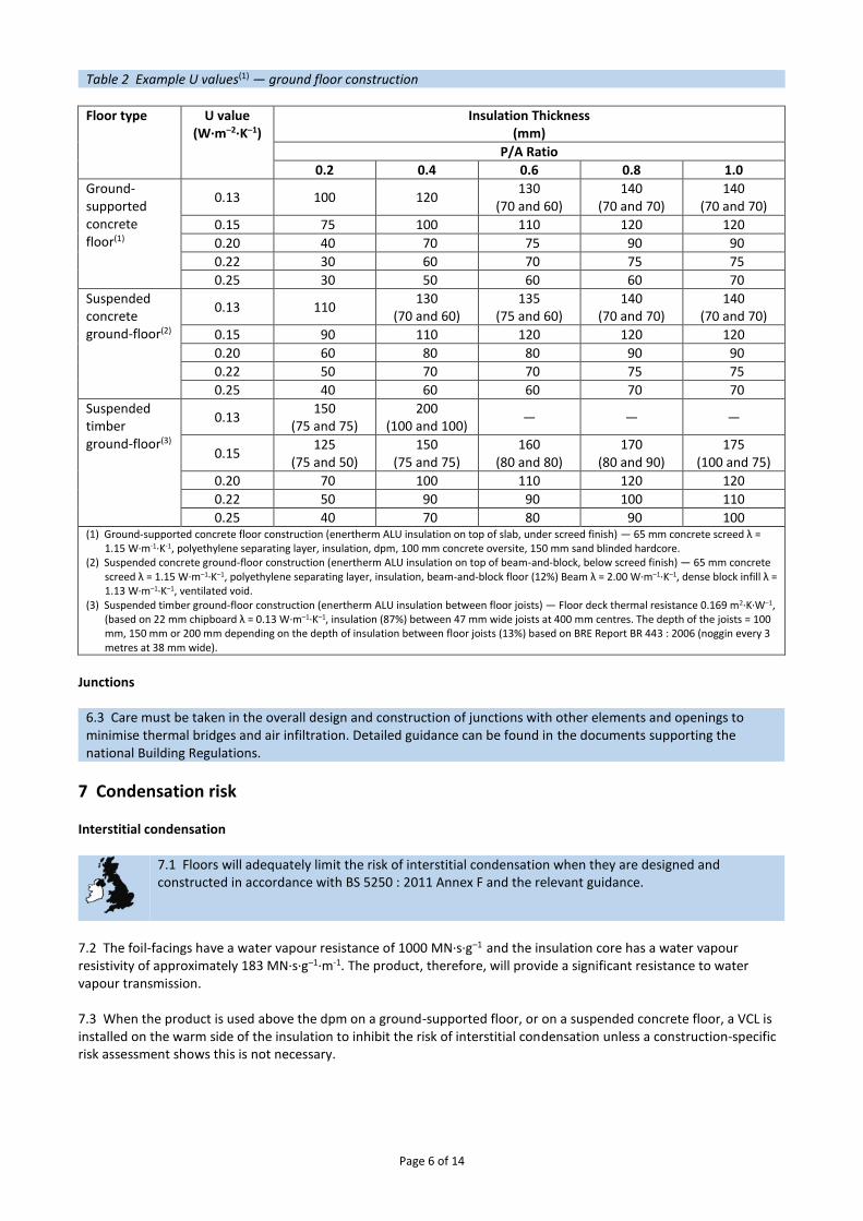
Page 6 of 14
Table 2 Example U values(1) — ground floor construction
Floor type U value (W·m–2·K–1)
Insulation Thickness (mm)
P/A Ratio
0.2 0.4 0.6 0.8 1.0
Ground-supported concrete floor(1)
0.13 100 120 130
(70 and 60) 140
(70 and 70) 140
(70 and 70)
0.15 75 100 110 120 120
0.20 40 70 75 90 90
0.22 30 60 70 75 75
0.25 30 50 60 60 70
Suspended concrete ground-floor(2)
0.13 110 130
(70 and 60) 135
(75 and 60) 140
(70 and 70) 140
(70 and 70)
0.15 90 110 120 120 120
0.20 60 80 80 90 90
0.22 50 70 70 75 75
0.25 40 60 60 70 70
Suspended timber ground-floor(3)
0.13 150
(75 and 75) 200
(100 and 100) — — —
0.15 125
(75 and 50) 150
(75 and 75) 160
(80 and 80) 170
(80 and 90) 175
(100 and 75)
0.20 70 100 110 120 120
0.22 50 90 90 100 110
0.25 40 70 80 90 100 (1) Ground-supported concrete floor construction (enertherm ALU insulation on top of slab, under screed finish) — 65 mm concrete screed λ =
1.15 W∙m-1∙K-1, polyethylene separating layer, insulation, dpm, 100 mm concrete oversite, 150 mm sand blinded hardcore. (2) Suspended concrete ground-floor construction (enertherm ALU insulation on top of beam-and-block, below screed finish) — 65 mm concrete
screed λ = 1.15 W∙m–1∙K–1, polyethylene separating layer, insulation, beam-and-block floor (12%) Beam λ = 2.00 W∙m–1∙K–1, dense block infill λ = 1.13 W∙m–1∙K–1, ventilated void.
(3) Suspended timber ground-floor construction (enertherm ALU insulation between floor joists) — Floor deck thermal resistance 0.169 m2∙K∙W–1, (based on 22 mm chipboard λ = 0.13 W∙m–1∙K–1, insulation (87%) between 47 mm wide joists at 400 mm centres. The depth of the joists = 100 mm, 150 mm or 200 mm depending on the depth of insulation between floor joists (13%) based on BRE Report BR 443 : 2006 (noggin every 3 metres at 38 mm wide).
Junctions
6.3 Care must be taken in the overall design and construction of junctions with other elements and openings to minimise thermal bridges and air infiltration. Detailed guidance can be found in the documents supporting the national Building Regulations.
7 Condensation risk Interstitial condensation
7.1 Floors will adequately limit the risk of interstitial condensation when they are designed and constructed in accordance with BS 5250 : 2011 Annex F and the relevant guidance.
7.2 The foil-facings have a water vapour resistance of 1000 MN·s·g–1 and the insulation core has a water vapour resistivity of approximately 183 MN·s·g–1∙m-1. The product, therefore, will provide a significant resistance to water vapour transmission. 7.3 When the product is used above the dpm on a ground-supported floor, or on a suspended concrete floor, a VCL is installed on the warm side of the insulation to inhibit the risk of interstitial condensation unless a construction-specific risk assessment shows this is not necessary.
Page 7 of 14
Surface condensation
7.4 Floors will adequately limit the risk of surface condensation when the thermal transmittance (U value) does not exceed 0.7 W·m–2·K–1 at any point, and the junctions with walls are designed in accordance with section 6.3 of this Certificate.
7.5 Floors will adequately limit the risk of surface condensation when the thermal transmittance (U value) does not exceed 1.2 W·m–2·K–1 at any point. Guidance may be obtained from BS 5250 : 2011 Annex F. Further guidance may be obtained from BRE Report BR 262 : 2002 and section 6.3 of this Certificate.
8 Behaviour in relation to fire 8.1 The product has a reaction to fire classification* of Class E to BS EN 13501-1 : 2007. 8.2 When properly installed, the product will not add significantly to any existing fire hazard. The product will be contained within the floor by the overlay until the overlay itself is destroyed. Therefore, the product will not contribute to the development stages of a fire or present a smoke or toxic hazard.
9 Floor loading 9.1 The compressive strength* of the product (compressive stress at 10% deformation to BS EN 826 : 2013) is ≥ 175 kPa.
9.2 The product is suitable for domestic occupancies defined in this Certificate when covered with a suitable floor overlay (see section 4.3), and is capable of resisting a uniformly distributed load of 1.5 kN·m-2 or a concentrated load of 2 kN for category A1 and A2 (domestic) situations as defined in BS EN 1991-1-1 : 2002, National Annex Table NA.2. Further assessment by a suitably competent and experienced individual is necessary in the case of duty walkways and floors subject to physical activities.
9.3 The performance of the floor construction will depend on the insulation properties and type of floor overlay used (including thickness and strength). Where the product is used under a concrete slab, resistance to concentrated and distributed loads is a function of the slab specification. Further guidance on the suitability of floor overlays can be found in BS EN 13810-1 : 2002, DD CEN/TS 13810-2 : 2003, BS 8204-1 : 2003 and BS EN 312 : 2010, and from the flooring manufacturer.
10 Maintenance As the product is confined within the floor by the overlay and has suitable durability (see section 11), maintenance is not required.
11 Durability
The product is durable, rot-proof, water resistant and sufficiently stable to remain effective as an insulation for the life of the building in which it is incorporated.
Installation
12 General 12.1 Installation of IKO enertherm ALU Insulation Board for Floors must be in accordance with the Certificate holder’s installation instructions and the requirements of this Certificate. 12.2 Typical methods of installation are shown in Figures 1 to 4. Reference should also be made to BRE Report BR 262 : 2002.

Page 8 of 14
Figure 1 Ground-supported concrete floor — screed overlay

Page 9 of 14
Figure 2 Ground-supported concrete floor — concrete slab overlay

Page 10 of 14
Figure 3 Suspended concrete beam-and-block floor — screed overlay
Figure 4 Suspended timber floor — board overlay
12.3 In ground-supported concrete floors the concrete floor slab over which the product is laid should be left for as long as possible to maximise drying out and dissipation of constructional moisture, in accordance with BS 8203 : 2001, Section 3.1.2.

Page 11 of 14
12.4 The concrete floor surface should be smooth, level and flat to within 5 mm when measured with a two metre straight-edge. Irregularities greater than this must be removed. Minor irregularities (up to 10 mm deep) may be levelled with mortar or thin screed. 12.5 Where the insulation is used over ground-supported concrete floor slabs, a suitable dpm in accordance with CP 102 : 1973 should be laid to resist moisture from the ground. If a liquid-type dpm is applied to the slab, it should be of a type compatible with the product and be allowed to dry out fully before laying the insulation. 12.6 Where the insulation is used on hardcore bases beneath ground-supported concrete slabs, the hardcore must be compacted and blinded with a thin layer of sand before application of the dpm, followed by the insulation boards. 12.7 A VCL is installed on the warm side of the insulation to inhibit the risk of interstitial condensation if necessary (see section 7.3). Where a concrete screed or slab finish is to be laid directly over the product, a polyethylene separating layer/VCL must be installed between the insulation and the concrete to prevent chemical attack and seepage between the boards. 12.8 The insulation can be used on suitable beam-and-block suspended concrete floors (see section 4.1). 12.9 Where a screed or concrete slab is laid over the insulation, vertical upstands of insulation should be provided and be of sufficient depth to fully separate the screed or slab from the wall. If used, a suitable cavity wall insulation material should be extended below the dpc level to provide edge insulation to the floor. 12.10 To limit the risk of damage from condensation and other sources of dampness, the insulation and overlays should only be laid after the construction is made substantially weathertight, eg after glazing. During construction, the insulation and overlay must be protected from damage by traffic and moisture sources such as water spillage and plaster droppings.
13 Procedure 13.1 The product is cut to size (using a sharp knife or fine toothed saw), as necessary, and laid with closely-butted, staggered cross-joints, ensuring that all spaces are completely filled. 13.2 The laying pattern should ensure that all cut edges are at the perimeter of the floor or some other feature, eg matwells, thresholds or access ducts. Spreader boards should be used to protect the insulation. Cement-based screed overlay (Figures 1 and 3) 13.3 Perimeter edge pieces are cut and placed around the edges and taped at joints. A polyethylene VCL, at least 0.125 mm thick (500 gauge), is laid over the insulation. The VCL should have 150 mm overlaps, taped at the joints, and be turned up 100 mm at the walls. A properly-compacted screed of a minimum 65 mm thickness is then laid over. The relevant clauses of BS 8204-1 : 2003 should be followed. Concrete slab overlay (ground-bearing only) (Figure 2) 13.4 Perimeter edge pieces are cut and placed around the edges and taped at joints. A polyethylene VCL, at least 0.125 mm thick (500 gauge), is laid over the insulation. The VCL should have 150 mm overlaps, taped at the joints, and be turned up 100 mm at the walls. The concrete slab is laid to the required thickness in accordance with BS 8000-9 : 2003 and BS 8204-1 : 2003. Timber based board overlay 13.5 Before laying the plywood, particle board or OSB overlays, preservative-treated timber battens, in accordance with BS 8417 : 2011, are positioned at doorways and access panels. Adequate time should be allowed for preservatives to be fixed and the solvents from solvent-based preservatives to evaporate. 13.6 Where the insulation is laid above a dpm, a polyethylene VCL of at least 0.125 mm (500 gauge) thickness is laid between the insulation and the timber board overlay. The VCL should have 150 mm overlaps, taped at the joints, and be turned up 100 mm at the walls.

Page 12 of 14
13.7 Timber-based overlay boards as specified in section 4.3 (of this Certificate) are laid with staggered cross-joints, in accordance with conventional good practice and DD CEN/TS 12872 : 2007 and BS EN 12871 : 2010. Suspended timber floor (Figure 4) 13.8 Insulation boards can be supported using timber joists using saddle clips or timber beads. Where timber beads are used, a void may be incorporated above the insulation to accommodate services, if required. 13.9 The product is cut to size to fit tightly between the joists. The clip spikes are pressed into the long edges of the insulation board, ensuring the flange sits flat on the face of the board. Clips should be fitted at one metre intervals. The insulation board is then pushed into place until the clip is level with the surface of the joist. 13.10 Where a service void is required above the insulation, preservative-treated timber beads may be used to retain the insulation boards. Beads should be wide enough to retain the insulation boards in place and secured with corrosion-resistant nails at a depth that will accommodate the thickness of the insulation board and leave a suitable depth void (minimum 25 mm) between the top of the insulation and the underside of the flooring deck. The product is cut to fit between the joists and pushed down onto the beads.
14 Incorporation of services 14.1 De-rating of electrical cables should be considered where the insulation restricts air cooling of cables; the product must not be used in direct contact with electrical heating cables or hot water pipes. Where underfloor heating systems are to be used, the advice of the Certificate holder should be sought. 14.2 Where possible, electrical conduits, gas and water pipes or other services should be contained within ducts or channels within the concrete slab of ground supported floors. Where this is not possible, the services may be accommodated within the insulation, provided they are securely fixed to the concrete slab. Electrical cables should be enclosed in a suitable conduit. With hot pipes, the insulation must be cut back to maintain an air space. 14.3 Where water pipes are installed below the insulation they must be pre-lagged with close-fitting pipe insulation. Pipes installed above the insulation will not require lagging, although some provision needs to be made for expansion and contraction. 14.4 Where the product is installed on a floor of a suspended beam-and-block design, all services must be installed so as not to impair the floor performance.
Technical Investigations
15 Tests An examination was made of data relating to: ● fire rating ● thermal conductivity ● compressive stress at 10% deformation ● dimensional accuracy ● diffusion tight property of facings ● water vapour resistance.
16 Investigations 16.1 A condensation risk analysis was carried out. 16.2 A series of U value calculations were carried out. 16.3 The manufacturing process was evaluated, including the methods adopted for quality control, and details were obtained of the quality and composition of the materials used.

Page 13 of 14
Bibliography BS 5250 : 2011 Code of practice for control of condensation in buildings BS 8000-9 : 2003 Workmanship on building sites — Cementitious levelling screeds and wearing screeds — Code of practice BS 8203 : 2001 Code of practice for installation of resilient floor coverings BS 8204-1 : 2003 Screeds, bases and in-situ floorings — Concrete bases and cement sand levelling screeds to receive floorings — Code of practice BS 8204-2 : 2003 Screeds, bases and in-situ floorings — Concrete wearing surfaces — Code of practice BS 8215 : 1991 Code of practice for design and installation of damp-proof courses in masonry construction BS 8417 : 2011 Preservation of wood — Code of practice BS EN 300 : 2006 Oriented Strand Boards (OSB) — Definitions, classification and specifications BS EN 312 : 2010 Particleboards — Specifications BS EN 636 : 2012 Plywood — Specifications BS EN 826 : 2013 Thermal insulating products for building applications — Determination of compression behaviour BS EN 1991-1-1 : 2002 Eurocode 1 : Actions on structures — General actions — Densities, self-weight, imposed loads for buildings NA to BS EN 1991-1-1 : 2002 UK National Annex to Eurocode 1 : Actions on structures — General actions — Densities, self-weight, imposed loads for buildings BS EN 1992-1-1 : 2004 Eurocode 2 : Design of concrete structures — General rules and rules for buildings BS EN 12871 : 2010 Wood-based panels — Performance specifications and requirements for load bearing boards for use in floors, walls and roofs BS EN 13165 : 2012 Thermal insulation products for buildings — Factory made rigid polyurethane foam (PU) products — Specification BS EN 13501-1 : 2007 Fire classification of construction products and building elements — Classification using test data from reaction to fire tests BS EN 13810-1 : 2002 Wood-based panels — Floating floors — Performance specifications and requirements BS EN 15037-1 : 2008 Precast concrete products — Beam-and-block floor systems — Beams BS EN 15037-2 : 2009 Precast concrete products — Beam-and-block floor systems — Concrete blocks BS EN 15976 : 2011 Flexible sheets for waterproofing. Determination of emissivity BS EN ISO 6946 : 2007 Building components and building elements — Thermal resistance and thermal transmittance — Calculation method BS EN ISO 13370 : 2007 Thermal performance of buildings — Heat transfer via the ground — Calculation methods BS EN ISO 14001 : 2004 Environmental management systems — Requirements with guidance for use CP 102 : 1973 Code of practice for protection of buildings against water from the ground DD CEN/TS 12872 : 2007 Wood-based panels — Guidance on the use of load-bearing boards in floors, walls and roofs DD CEN/TS 13810-2 : 2003 Wood-based panels — Floating floors — Test methods
Page 14 of 14
BRE Report (BR 262 : 2002) Thermal insulation: avoiding risks BRE Report (BR 443 : 2006) Conventions for U-value calculations
Conditions of Certification
17 Conditions 17.1 This Certificate: ● relates only to the product/system that is named and described on the front page ● is issued only to the company, firm, organisation or person named on the front page – no other company, firm,
organisation or person may hold claim that this Certificate has been issued to them ● is valid only within the UK ● has to be read, considered and used as a whole document – it may be misleading and will be incomplete to be
selective ● is copyright of the BBA ● is subject to English Law. 17.2 Publications, documents, specifications, legislation, regulations, standards and the like referenced in this Certificate are those that were current and/or deemed relevant by the BBA at the date of issue or reissue of this Certificate. 17.3 This Certificate will remain valid for an unlimited period provided that the product/system and its manufacture and/or fabrication, including all related and relevant parts and processes thereof: ● are maintained at or above the levels which have been assessed and found to be satisfactory by the BBA ● continue to be checked as and when deemed appropriate by the BBA under arrangements that it will determine ● are reviewed by the BBA as and when it considers appropriate. 17.4 The BBA has used due skill, care and diligence in preparing this Certificate, but no warranty is provided. 17.5 In issuing this Certificate the BBA is not responsible and is excluded from any liability to any company, firm, organisation or person, for any matters arising directly or indirectly from: ● the presence or absence of any patent, intellectual property or similar rights subsisting in the product/system or any
other product/system ● the right of the Certificate holder to manufacture, supply, install, maintain or market the product/system ● actual installations of the product/system, including their nature, design, methods, performance, workmanship and
maintenance ● any works and constructions in which the product/system is installed, including their nature, design, methods,
performance, workmanship and maintenance ● any loss or damage, including personal injury, howsoever caused by the product/system, including its manufacture,
supply, installation, use, maintenance and removal ● any claims by the manufacturer relating to CE marking. 17.6 Any information relating to the manufacture, supply, installation, use, maintenance and removal of this product/system which is contained or referred to in this Certificate is the minimum required to be met when the product/system is manufactured, supplied, installed, used, maintained and removed. It does not purport in any way to restate the requirements of the Health and Safety at Work etc. Act 1974, or of any other statutory, common law or other duty which may exist at the date of issue or reissue of this Certificate; nor is conformity with such information to be taken as satisfying the requirements of the 1974 Act or of any statutory, common law or other duty of care.
British Board of Agrément Bucknalls Lane Watford Herts WD25 9BA
©2016
tel: 01923 665300 fax: 01923 665301
[email protected] www.bbacerts.co.uk
Top Related