Hot Insulations Varios Materiales y Tablas
9
Page 7 3. HOT INSULATION 3.1 GENERAL NOTES Equipment or pipe work with an operation temperature greater than 55°C in case of metallic surfaces and 65°C in the case of non-metallic surfaces should be insulated so that the surface temperature after insulation (cold surface temperature) does not exceed 55°C. It is recognised that temperatures of 60°C or greater will result in extreme discomfort to personnel and therefore a maximum cold surface temperature of 55°C should be considered as prudent. If the fluid inside the pipe or vessel is likely to remain static for long periods when the ambient temperature is below the freezing point of the fluid, it is important that this shall be stated. Also, the flu id in small diameter pipes may be espe cially suscept ible to freezing, particularly if the rate of flow is intermittent or slow, it may be necessary to consider the use of supplementary means of heating, possibly only in local areas, like heat tracing. 3.2 SELECTION OF HOT INSULATION MATERIALS The objective is to select a material, which will serve the insulation purpose at the lowest cost. This can be a complicated procedure. In addition to the factors listed in section 2.2 careful considerations should be given to insulation thickness. On pipe work an over-specification of thickness creates a needless increase in the cost of the outer protection. When a multi-layer system of insulation is envisaged, the selection of materials is interdependent on the type of protection and the calculations as set out in Annex 2 paragraph 5.2. For example, an alumini um protection will re sult in a higher cold surface temperature and a lower heat. (Aluminium protection has a low emissivity and therefore radiates less heat). Where constant load supports are involved, the mass of the insulation system becomes critical and must be kept wi thin the tolerances of such const ant load supports. Where used for internal linings of ventilation ductwork the thermal insulating material itself should be non-combustible as defined in BS 476: Part 4 3.3 HOT INSULATION MATERIALS Common to all these materials, it is recommended that their use be limited to conditions of 90% of the manufacturer’s limiting temperatures in order to safeguard against temperature surge at start-up operations of plant. Please note: Information provided in the following tables is generic information suitable for feasibility studies and cost estimates. Actual figures may differ from manufacturer to manufacturer and must be confirmed with the individual manufacturer.
Transcript of Hot Insulations Varios Materiales y Tablas
8/3/2019 Hot Insulations Varios Materiales y Tablas
http://slidepdf.com/reader/full/hot-insulations-varios-materiales-y-tablas 1/9
Page 7
3. HOT INSULATION
3.1 GENERAL NOTES
Equipment or pipe work with an operation temperature greater than 55°C in case of
metallic surfaces and 65°C in the case of non-metallic surfaces should be insulated so that
the surface temperature after insulation (cold surface temperature) does not exceed 55°C.
It is recognised that temperatures of 60°C or greater will result in extreme discomfort to
personnel and therefore a maximum cold surface temperature of 55°C should beconsidered as prudent.
If the fluid inside the pipe or vessel is likely to remain static for long periods when the
ambient temperature is below the freezing point of the fluid, it is important that this shall
be stated. Also, the fluid in small diameter pipes may be especially susceptible to
freezing, particularly if the rate of flow is intermittent or slow, it may be necessary toconsider the use of supplementary means of heating, possibly only in local areas, like heat
tracing.
3.2 SELECTION OF HOT INSULATION MATERIALS
The objective is to select a material, which will serve the insulation purpose at the lowestcost. This can be a complicated procedure.
In addition to the factors listed in section 2.2 careful considerations should be given to
insulation thickness. On pipe work an over-specification of thickness creates a needless
increase in the cost of the outer protection.
When a multi-layer system of insulation is envisaged, the selection of materials isinterdependent on the type of protection and the calculations as set out in Annex 2
paragraph 5.2. For example, an aluminium protection will result in a higher cold surface
temperature and a lower heat. (Aluminium protection has a low emissivity and therefore
radiates less heat).
Where constant load supports are involved, the mass of the insulation system becomes
critical and must be kept within the tolerances of such constant load supports. Where
used for internal linings of ventilation ductwork the thermal insulating material itself
should be non-combustible as defined in BS 476: Part 4
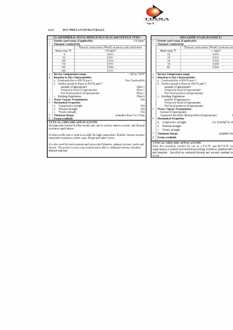
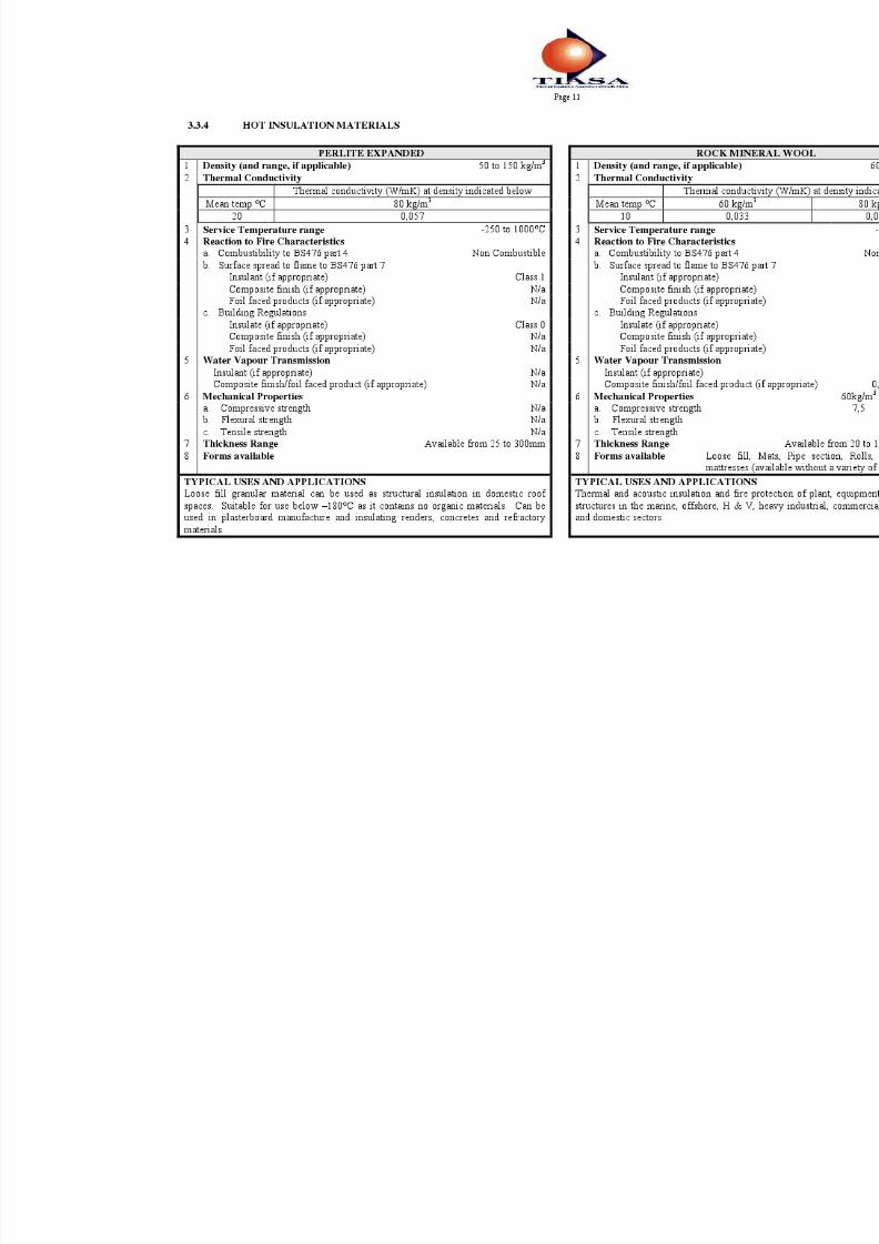
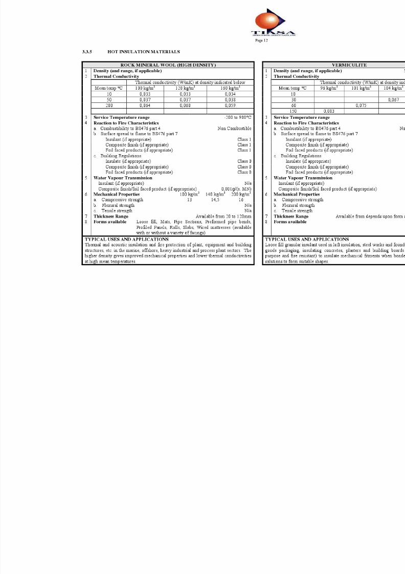
3.3 HOT INSULATION MATERIALS
Common to all these materials, it is recommended that their use be limited to conditionsof 90% of the manufacturer’s limiting temperatures in order to safeguard against
temperature surge at start-up operations of plant.
Please note: Information provided in the following tables is generic information
suitable for feasibility studies and cost estimates.
Actual figures may differ from manufacturer to manufacturer and must
be confirmed with the individual manufacturer.

8/3/2019 Hot Insulations Varios Materiales y Tablas
http://slidepdf.com/reader/full/hot-insulations-varios-materiales-y-tablas 2/9

8/3/2019 Hot Insulations Varios Materiales y Tablas
http://slidepdf.com/reader/full/hot-insulations-varios-materiales-y-tablas 3/9
8/3/2019 Hot Insulations Varios Materiales y Tablas
http://slidepdf.com/reader/full/hot-insulations-varios-materiales-y-tablas 4/9
8/3/2019 Hot Insulations Varios Materiales y Tablas
http://slidepdf.com/reader/full/hot-insulations-varios-materiales-y-tablas 5/9
8/3/2019 Hot Insulations Varios Materiales y Tablas
http://slidepdf.com/reader/full/hot-insulations-varios-materiales-y-tablas 6/9

8/3/2019 Hot Insulations Varios Materiales y Tablas
http://slidepdf.com/reader/full/hot-insulations-varios-materiales-y-tablas 7/9
Page 13
3.4 RECOMMENDED THICKNESS OF HOT INSULATION
NB: This should be regarded as a general guide, and depending on relative fuel cost andcost of applied insulation, the indicated thickness need not necessarily be the most
economic thickness of insulation.
Criteria used in selection below:
• To achieve an approximate cold surface temperature of 55°C
• Ambient of 20°C
• Zero wind speed
• Galvanized cladding
3.4.1 FIBREGLASS
3.4.1.1 FIBIREGLASS FLAT SURFACES
Operating
temperature range
(°C)
Fibreglass insulation density
(kg/m3)
Thickness of insulation
(mm)
Up to 200 24 40
201 to 250 24 40
251 to 300 47,5 70*
301 to 350 64 75*
351 to 400 64 100*
401 to 450 64 125*
Remarks: * Non-standard thickness
Double layer recommended. With double layer, first layer should be 40 to 50mm.
Second layer can be in lower density product, but this should be checked with theinsulation supplier.
3.4.1.2 FIBREGLASS PREFORMED PIPE SECTION
Operating temperaturerange (°C)
Nominal bore range
(Mm)
Thickness of
insulation (mm)
0 to 100101 to 200
201 to 250251 to 300301 to 350351to 400
15 - 32
1520
25405060*
0 to 100
101 to 200201 to 250251 to 300301 to 350351 to 400
40 - 100
20
25405060*70*
0 to 200201 to 250
251 to 300301 to 350351 to 400
125 - 200
2540
5070*80*
0 to 200201 to 250
251 to 300301 to 350351 to 400
225 - 400
3540
5070*90*
Remarks: * Non-standard thickness

8/3/2019 Hot Insulations Varios Materiales y Tablas
http://slidepdf.com/reader/full/hot-insulations-varios-materiales-y-tablas 8/9
Page 14
3.4.2 ROCKWOOL
3.4.2.1 FLAT SURFACES
Most suitable productOperating Temperature
(°C) Density (kg/m3) Thickness (mm)
50 - 199200 - 249250-299300-349350-399400-449450-499500-549
550-599(Two layers)
600-649
(Two layers)650-700
(Three layers)
60608080100120120160
160+120160
+120160
+120
+100
254050757575100100
407550
1005050
100
3.4.2.2 ROCKWOOL – Preformed pipe section
Operating temperaturerange (°C)
Nominal bore range
(mm)
Thickness of insulation
(mm)
0 to 100101 to 200
201 to 250251 to 300301 to 350351 to 400
15 - 32
2020
25304050
0 to 100101 to 200201 to 250251 to 300
301 to 350351 to 400
40 - 100
20253040
5060
0 to 200201 to 250
251 to 300301 to 350351 to 400
125 - 200
2530
405060
0 to 200201 to 250251 to 300301 to 350351 to 400
225 - 400
2530405060
0 to 200201 to 250
251 to 300301 to 350
351 to 400
350-400
4040
5060
70

8/3/2019 Hot Insulations Varios Materiales y Tablas
http://slidepdf.com/reader/full/hot-insulations-varios-materiales-y-tablas 9/9
Page 15
3.5 APPLICATION OF HOT INSULATION
Pipe section, mattress or any flexible insulation may be used for pipe work. However, practical reasons preclude the use of mattress or flexible insulation where the outside diameter
of the pipe or the outside diameter of any previous layer of insulation is 200mm or less.
Where mattress or materials of low density are used and metal is the protection medium,supports should be provided for the metal at not more than 1-metre intervals where the pipework is horizontal or inclined up to 45°. Between 45° and the vertical the spacing of thesupports is dependent on temperature and expansion requirements. (Refer BS 5970).
As a guide, the expansion allowances on pipe work are generally 1mm per running meter per 100°C of temperature. In all applications of insulation the material must be well buttedtogether and in the case of multi-layer applications all joints of each subsequent layer must bestaggered from the previous layer. Weld pins or clips, binding wire and strapping are used for securing the insulation as a single or composite system dependent on the circumstances.