


Languages
Pages
Legal

Schweitzer Engineering Laboratories, Inc. SEL-487V Data Sheet
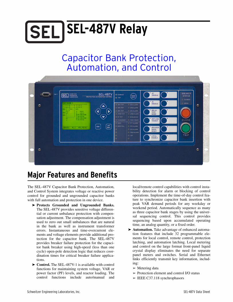
Capacitor Bank Protection,Automation, and Control
Major Features and BenefitsThe SEL-487V Capacitor Bank Protection, Automation,and Control System integrates voltage or reactive powercontrol for grounded and ungrounded capacitor bankswith full automation and protection in one device.
➤ Protects Grounded and Ungrounded Banks.The SEL-487V provides sensitive voltage differen-tial or current unbalance protection with compen-sation adjustment. The compensation adjustment isused to zero out small unbalances that are naturalin the bank as well as instrument transformererrors. Instantaneous and time-overcurrent ele-ments and voltage elements provide additional pro-tection for the capacitor bank. The SEL-487Vprovides breaker failure protection for the capaci-tor bank breaker using high-speed (less than onecycle) open-pole detection logic that reduces coor-dination times for critical breaker failure applica-tions.
➤ Control. The SEL-487V-1 is available with controlfunctions for maintaining system voltage, VAR orpower factor (PF) levels, and reactor loading. Thecontrol functions include auto/manual and
local/remote control capabilities with control insta-bility detection for alarm or blocking of controloperations. Implement the time-of-day control fea-ture to synchronize capacitor bank insertion withpeak VAR demand periods for any weekday orweekend period. Automatically sequence as manyas three capacitor bank stages by using the univer-sal sequencing control. This control providessequencing based upon accumulated operatingtime, an analog quantity, or a fixed order.
➤ Automation. Take advantage of enhanced automa-tion features that include 32 programmable ele-ments for local control, remote control, protectionlatching, and automation latching. Local meteringand control on the large format front-panel liquidcrystal display eliminates the need for separatepanel meters and switches. Serial and Ethernetlinks efficiently transmit key information, includ-ing:➢ Metering data➢ Protection element and control I/O status➢ IEEE C37.118 synchrophasors
SEL-487V Relay

SEL-487V Data Sheet Schweitzer Engineering Laboratories, Inc.
2
➢ IEC 61850 GOOSE messages➢ Sequential events recorder (SER) reports➢ Breaker monitor➢ Relay summary event reports➢ Time synchronization
Expanded SELOGIC® control equations with mathand comparison functions are available for controland protection applications. Incorporate up to 1000lines of automation logic to speed and improvecontrol actions.
➤ Simple Application-Based Settings. TheSEL-487V selects the recommended capacitorbank protection elements based upon capacitorbank nameplate and configuration settings. Therelay selects from differential voltage, differentialneutral voltage, neutral-current unbalance, andphase-current unbalance protection.
➤ Faulted Phase and Section Identification Logic.Reduce the time needed to identify faulted capaci-tor bank units with the patent-pending faultedphase and section identification logic. This logicautomatically determines the phase (A, B, C) andsection (top/bottom or left/right) where the faultycapacitor bank unit is located.
➤ Simple Settings Assistance. Simplify settings cal-culations for grounded wye capacitor bank applica-tions with the SEL capacitor bank settingsassistance software. This software runs as a toolwithin ACSELERATOR QuickSet® SEL-5030 Soft-ware. ACSELERATOR QuickSet and the SettingsAssistant are available at no charge from SEL.
➤ Synchrophasors. Make informed system opera-tional decisions based on actual real-time phasormeasurements from across your power system.Synchrophasors can determine actual stability mar-gins using a standard spreadsheet, graphics pro-gram, or data management system. Record up to120 seconds of C37.118 binary synchrophasordata, and perform real-time control using remoteand local synchrophasor data.
➤ Breaker Monitoring and Control. Schedulebreaker maintenance when accumulated breakerduty (independently monitored for each pole of thecircuit breaker) indicates possible excess contactwear. Electrical and mechanical operating timesare recorded for both the last operation and theaverage of operations since function reset. Alarmcontacts provide notification of substation batteryvoltage problems even if voltage is low only duringtrip or close operations. Motor run time monitoringdetects failing charging mechanism motors. Con-trol the breaker remotely or locally using optionaldirect action pushbuttons.
➤ Ethernet Access. Access all relay functions withthe optional Ethernet card. Interconnect with auto-mation systems using IEC 61850 or DNP3 proto-col directly. Optionally connect to DNP3 networksthrough an SEL-2032 Communications Processor.File transfer protocol (FTP) is provided for high-
speed data collection. Connect to substation or cor-porate LANs to transmit synchrophasors in theIEEE C37.118-2005 format using TCP or UDPInternet protocols.
➤ Simple Network Time Protocol (SNTP). Therelay shall be capable of synchronizing the internaltimekeeping to a network time source.
➤ IEC 60255-Compliant Thermal Model. Therelay provides a configurable thermal model forthe protection of a wide variety of devices.
➤ Digital Relay-to-Relay Communications.Enhanced MIRRORED BITS® communications canmonitor relay element conditions between bankswithin a station, or between stations, using SELfiber-optic transceivers. Send digital, analog, andvirtual terminal data over the same MIRROREDBITS channel.
➤ Sequential Events Recorder (SER). Record thelast 1000 entries, including setting changes, power-ups, and selectable logic elements.
➤ Comprehensive Metering. Improve system loadprofiles by using built-in, high-accuracy meteringfunctions. Power Factor and VAR measurementsoptimize capacitor bank operation. Minimizeequipment needs with full metering capabilitiesincluding rms, maximum/minimum, demand/peak,energy, and instantaneous values.
➤ Parallel Redundant Protocol (PRP). Available inSEL-487V relays equipped with Ethernet, PRPprovides redundancy by assigning each of the twoavailable Ethernet ports to separate networks carry-ing identical information.
➤ High-Accuracy Time-Stamping. Time-tag binaryCOMTRADE event reports with real-time accu-racy of better than 10 µs. View system state infor-mation to an accuracy of better than a quarter of anelectrical degree.
➤ Oscillography and Event Reporting. Recordvoltages and currents at up to 8 kHz sampling rate.Record up to 24 seconds of 1 kHz COMTRADEevent data for each event, and store at least five ofthese events in nonvolatile memory within therelay. Off line phasor and harmonic analysis fea-tures allow investigation of relay and system per-formance.
➤ Harmonic Metering. The relay provides individ-ual harmonic content from fundamental throughthe 15th harmonic for all current and voltage chan-nels. Total Harmonic Distortion shall be providedas a percentage of the fundamental.
➤ Thermal Overload Protection. The SEL-487Vwith the SEL-2600A RTD Module providesdynamic thermal overload protection usingSELOGIC control equations.
➤ Rules-Based Settings Editor. Communicate withand set the relay with an ASCII terminal, or use thePC-based ACSELERATOR QuickSet to configurethe SEL-487V and analyze fault records with relayelement response.

Schweitzer Engineering Laboratories, Inc. SEL-487V Data Sheet
3
➤ Configurable Synchrophasor Data Streams. Therelay supports up to five unique synchrophasordata streams over Ethernet. Each data stream shallprovide selectable voltage and current quantitieswith configurable data labels.
➤ Auxiliary Trip/Close Pushbuttons. Theseoptional pushbuttons are electrically isolated fromthe rest of the relay. They function independentlyfrom the relay and do not need relay power.
➤ Directional Elements. Phase and ground direc-tional elements shall be provided with voltagepolarization.
Functional Overview
Figure 1 Functional Diagram
Table 1 Protection Elements (Sheet 1 of 2)
Element ANSI Number Description Quantity
27 Undervoltage 6
32 Directional Power 10
46 Current Unbalance 1
50 Instantaneous Overcurrent 3 Phase, 3 Negative-Sequence, 3 Ground
50BF Breaker Failure 1
51S Selectable Time Overcurrent 10
59 Overvoltage 6
60N Neutral-Current Unbalance 3
60P Phase-Current Unbalance 3
87V Voltage Differential 3
87VN Neutral-Voltage Differential 3
LOP Loss of Potential 2
ANSI NUMBERS/ACRONYMS AND FUNCTIONS
27P
27 (P, Q, B)
32 (P, G)
37C
46P
49
50BF
50FO
50 (P, G, Q)
51 (P, G, Q)
59 (P, G, B)
60
60N
60P
67 (P, G, Q)
81 (O, U, R)
85 RIO
87V
87VN
DFR
HMI
LGC
MET
PMU
RTU
SER
ADDITIONAL FUNCTIONS
BRM
LDP
1 Copper or Fiber Optic * Optional Feature
Phase Undervoltage
Undervoltage (Phase, Neg. Seq., Bank)
Real and Reactive Power (Phase, Ground)
Undercurrent
Phase Current Unbalance
Programmable Thermal Control and Logic
Breaker Failure Overcurrent
Flashover Overcurrent
Overcurrent (Phase, Ground, Neg. Seq.)
Time-Overcurrent (Phase, Ground, Neg. Seq.)
Overvoltage (Phase, Neg. Seq., Bank)
Loss-of-Potential
Neutral Current Unbalance
Phase Current Unbalance
Directional Overcurrent (Phase, Ground, Neg. Seq.)
Frequency (Over, Under, Rate)
SEL MIRRORED BITS Communications
Tapped Current Differential
Neutral Voltage Differential
Event Reports
Operator Interface
Capacitor Bank Control*
High-Accuracy Metering
Synchrophasors
Remote Terminal Unit
Sequential Events Recorder
Breaker Wear Monitor
Load Data Profiling*
1
1
3
31
SEL-2600
SEL-2800
ENV
52
3
49
60N 60P
87V
46
27
87VN
50FO
27
50PGQ
81OUR
59PQT
59PQB
51 67PGQ
BRM
DFR HMI MET PMURTU
LOP50BF85RIOSER
4
EIA-232
2
Ethernet1*
1
IRIG-B
SEL-487V
32
LGC
37C

SEL-487V Data Sheet Schweitzer Engineering Laboratories, Inc.
4
Protection FeaturesPhase-Voltage Differential Elements
Figure 2 Phase-Voltage Differential One-Line Diagram
The SEL-487V provides three phase-voltage differentialelements. These elements are used to measure voltagedifferences between bus or line phase voltages and thetapped voltage of the grounded wye capacitor bank. Eachphase-voltage differential element is provided with adifferential voltage-nulling algorithm, referred to as theKSET function. A KSET command is issued to the relayvia serial or Telnet communications. Once received bythe relay, the KSET command acts to zero out anyexisting voltage differential. The KSET function isintended to provide a means for removing small voltagedifferential levels due to variations in individualcapacitor elements from manufacturing, potentialtransformer, or CCVT measurement error.
Each phase differential element is provided with threelevels of detection, each with its own definite-time delay.A low-set alarm level, trip pickup level, and high-leveltrip pickup are provided.
The phase differential elements are used to detectvariations in capacitor bank impedance, due to loss ofindividual capacitor elements, an entire capacitor can or
an entire group of capacitor cans. Two cycle cosinefiltering is used to minimize voltage transients due to lineswitching operations.
Neutral-Voltage Differential Elements
Figure 3 Neutral-Voltage Differential One-Line Diagram
The SEL-487V provides three neutral-voltagedifferential elements for protection of up to threeungrounded wye capacitor banks. The neutral-voltagedifferential elements of the SEL-487V calculate zero-sequence voltage from the three-phase potential inputsprovided from the line or bus. The zero-sequence voltageis then compared to the zero-sequence voltage measuredby a potential transformer connected between thecapacitor bank neutral and ground. As with the phasedifferential elements, the neutral-voltage differentialelement uses a KSET nulling function to eliminatedifferential voltage caused by manufacturing tolerancesof the capacitor bank and voltage measurement devices.Sensitive measurement of the inputs allows as little as 30millivolts of differential voltage to be detected.
Each neutral-voltage differential element is providedwith three pickup levels with independent definite-timedelay. The three levels provide alarm, trip, andcatastrophic failure protection for the capacitor bank.
CTL Automatic Voltage Control 3
59T Inverse-Time Overvoltage Elements
Table 1 Protection Elements (Sheet 2 of 2)
Element ANSI Number Description Quantity
87V
27P,Q
59P,Q
32PF
27P,Q,G
59P,Q,G
81O,U
3
3
1 3
SEL-487V
IAW, IBW, ICW
VAY, VBY, VCYIX1
VAZ, VBZ, VCZ
4650
P,Q,G51
P,Q,G50
BF,FO
LineBusbar
52
87V
32PF
27P,Q,G
59P,Q,G
81O,U
3
1
1 3
SEL-487V
IAW, IBW, ICW
VAY, VBY, VCYIX1
VAZ
4650
P,Q,G51
P,Q,G50
BF,FO
LineBusbar
52

Schweitzer Engineering Laboratories, Inc. SEL-487V Data Sheet
5
Phase-Current Unbalance Elements
Figure 4 Phase-Current Unbalance One-Line Diagram
The SEL-487V protects grounded and ungroundeddouble-wye capacitor bank applications with phase-current unbalance detection. The SEL-487V providesthree independent phase-current unbalance elementswith KSET nulling functions. The phase unbalanceelements use the positive-sequence current as a referenceto enhance sensitivity and provide a directionalindication. Fault direction is indicated based upon thepolarity of the phase-current transformer connection tothe relay.
Each phase-current unbalance element is provided withthree pickup levels, with independent definite-time delay.
Neutral-Current Unbalance ElementsProtect ungrounded capacitor bank configurations withthe SEL-487V neutral-current unbalance elements.Three elements are provided for protection of up to threeparallel capacitor banks. Each element is provided withthree levels of pickup with definite-time delay.
KSET nulling is provided for each neutral-currentelement, and is activated by issuing the KSET commandvia relay serial port or through Telnet session with therelay.
Figure 5 Neutral-Current Unbalance One-Line Diagram
Overcurrent ElementsThe SEL-487V calculates instantaneous overcurrentelements for phase, negative-sequence, and zero-sequence currents. The relay offers three levels of phase,negative-, and zero-sequence overcurrent protection forthe W terminal current inputs. Torque control is providedfor each element.
The SEL-487V also includes ten selectable operatingquantity inverse-time overcurrent elements. You canselect the operating quantities from the following:
➤ IA➤ IB➤ IC➤ MAX (IA, IB, IC) (where IA, IB, IC can be funda-
mental or rms quantities from Terminal W)➤ I1➤ 3I2➤ IG
Individual torque control settings are provided for eachtime-overcurrent element.
The time-overcurrent curves (listed in Table 2) have tworeset characteristic choices for each time-overcurrentelement. One choice resets the elements if current dropsbelow pickup for one cycle. The other choice emulatesthe reset characteristic of an electromechanical inductiondisc relay.
Undercurrent ElementsThe relay includes six undercurrent elements, each withtwo levels, for a total of 12 undercurrent outputs fordetecting loss of load conditions. All 12 elementsprovide both instantaneous and time-delayed outputs.You can use SELOGIC control equations to switch the 12elements in or out of service.
60P
27P,Q,G
59P,Q,G
81O,U
3
3
3
SEL-487V
IAW, IBW, ICW
VAY, VBY, VCY
IX1, IX2, IX3
4650P,Q,G
51P,Q,G
50BF,FO
Busbar
52
60N
27P,Q,G
32P,F
59P,Q,G
81O,U
3
1
3
SEL-487V
IAW, IBW, ICW
VAY, VBY, VCY
IX2
4650
P,Q,G51
P,Q,G50
BF,FO
1 IX1
LineBusbar
52
Table 2 Time-Overcurrent Curves
US IEC
Moderately Inverse Standard Inverse
Inverse Very Inverse
Very Inverse Extremely Inverse
Extremely Inverse Long-Time Inverse
Short-Time Inverse Short-Time Inverse
SEL-487V Data Sheet Schweitzer Engineering Laboratories, Inc.
6
Voltage ElementsThe SEL-487V provides six independent over- andundervoltage elements with two pickup levels. The firstpickup level is provided with a definite-time delay.Choose from a wide range of fundamental and rmsoperating quantities for the Y and Z terminal voltageinputs. Table 3 shows the voltage inputs available for useas operating quantities.
Inverse-Time Overvoltage ElementsSix inverse-time overvoltage elements are provided, andare designed to meet the IEC 60871-1:2005 standard formaximum allowable overvoltage for capacitor banks inservice. Selectable operating quantities provideflexibility for the input to the inverse time overvoltageelements, and the built-in logic tracks overvoltageduration with respect to operating time.
Frequency ElementsThe SEL-487V provides six frequency elements, drivenfrom either the Y or the Z potential transformers. Any ofthe six elements may be configured for over- or under-frequency. Each frequency element provides a pickuptime delay setting. The frequency elements aresupervised by a programmable undervoltage element.The undervoltage element can be set to monitor either Yor Z potential inputs, and will block the assertion of the81 element when the selected voltage input falls below aprogrammable undervoltage supervision threshold.
Current UnbalanceThe SEL-487V uses the average three-phase terminalcurrent on the W current terminals to calculate thepercentage difference between the individual phasecurrent and the terminal average current. If thepercentage difference is greater than the set pickup valuethe phase unbalance element is asserted. To prevent thiselement from asserting during fault conditions and after aterminal circuit breaker has closed, the final terminalunbalance output (46nP) is supervised, using current,
fault detectors, and the open-phase detection logic. Thecurrent unbalance logic is blocked from operating if anyof the following conditions is true:
➤ The mean terminal current is less than 5% orgreater than 200% of I nominal (INOM = 1 A or 5 A)
➤ The FAULT Relay Word is asserted➤ The circuit breaker has been closed (open phase
detection element has deasserted for a settabledropout period)
Breaker Failure ProtectionIncorporated into the SEL-487V is a full functionbreaker failure system. High-speed open-pole detectionlogic allows you to set the pickup current belowminimum load for sensitivity without sacrificing high-speed dropout. Even in cases with delayed current zero inthe secondary of the CT caused by trapped flux, high-speed detection of circuit breaker opening is achieved.This feature is essential if breaker failure is initiated onall circuit breaker trips. A reset of less than one cyclereduces coordination times, improving stability.
Breaker Flashover DetectionThe SEL-487V provides logic to detect a reignition orrestrike (also called flashover) across any one of the threebreaker poles of the W terminal breaker after the breakerhas opened.
The SEL-487V uses rms current measurement and open-phase detection logic to detect breaker flashoverconditions that may exist during capacitor switchingoperations.
Multiple restrike or reignition conditions are typicallyindicative of contaminated dielectric material, reducedbreaker contact separation, or an improperly rated breaker.
Thermal Overload ProtectionThe SEL-487V provides three independent IEC thermalmodels for thermal overload protection of a variety ofdevices, including in-line reactors used to limit capacitorbank switching transients.
Ambient temperature measurements for the thermalmodel are provided using the SEL-2600 RTD Module.
Loss-of-Potential (LOP) Logic Supervises Voltage ElementsThe SEL-487V includes logic to detect a loss-of-potential (LOP) caused by failures such as blown fuses,which can cause an incorrect operation in voltageelements. Configure the LOP logic to block voltagedifferential elements under these conditions. The logicchecks for a sudden change in positive-sequence voltage
Table 3 Voltage Element Operating Quantities
Analog Quantity Description
VA, VB, VC L–N Phase Voltage
VNMAX, VNMIN Neutral Voltage Min/Max
VAB, VBC, VCA L–L Phase Voltage
VA–VNa, VB–VNa, VC–VNa
a Fundamental quantities only.
Phase Voltage with Neutral Voltage Subtracted
VPMAX, VPMIN Phase Voltage Min/Max
V1a, 3V2a, 3V0a Positive-, Negative-, Zero-Sequence

Schweitzer Engineering Laboratories, Inc. SEL-487V Data Sheet
7
without a corresponding change in positive- or zero-sequence current. Tests and field experience show thatthis principle is very secure and is faster than the trippingelements.
Faulted Phase and Section Identification LogicThe SEL-487V makes sensitive measurements of themagnitude and phase angle of differential quantitiesgenerated by the failure of fuses or elements within thecapacitor bank. The SEL-487V uses these measurementsto automatically determine the faulted phase (A, B, C)and section (top, bottom or left, right) in grounded andungrounded capacitor bank applications. The faultedphase and section identification logic can be used toprovide local or remote indication of the problem areawithin the capacitor bank so that fault location
identification times are reduced. The faulted phase andsection identification logic is processed each time adifferential alarm, trip, or high-set element asserts.
Six Independent Settings Groups Increase Operation FlexibilityThe relay stores six settings groups. Select the activesettings group by control input, command, or otherprogrammable conditions. These settings groups cancover a wide range of control contingencies andoperating conditions. Selectable settings groups make theSEL-487V ideal for applications requiring frequentsettings changes and for adapting to changing systemconditions.
Selecting a group also selects logic settings. Programgroup logic to adjust settings for different operatingconditions, such as station maintenance, seasonaloperations, emergency contingencies, loading, sourcechanges, and adjacent relay settings changes.
Local Control
The SEL-487V provides dynamic one-line bay diagramson the front-panel screen with disconnect and breakercontrol capabilities for predefined user-selectable baytypes. The relay is equipped to control as many as tendisconnects and a single breaker, depending on the one-line diagram selected. Operate disconnects and thebreaker with ASCII commands, SELOGIC controlequations, Fast Operate messages, and from the one-linediagram. The one-line diagram includes user-configurable apparatus labels and as many as six user-definable analog quantities.
One-Line Bay DiagramsThe SEL-487V offers a variety of preconfigured one-linediagrams for common bus and capacitor bankconfigurations. Once a one-line diagram is selected, theuser has the ability to customize the names for all of thedisconnect switches, capacitor bank, buses, and breaker.Most one-line diagrams contain analog display points.These display points can be set to any of the availableanalog quantities with labels, units, and scaling. Thesevalues are updated real-time along with the breakers andswitch position to give instant status and completecontrol of a bay.
The operator can see all valuable information on a baybefore making a critical control decision. Programmableinterlocks help prevent operators from incorrectlyopening or closing switches or breakers. The SEL-487V
will not only prevent the operator from making anincorrect control decision, but can notify and/or alarmwhen an incorrect operation is initiated.
Circuit Breaker Operations From the Front PanelThe one-line diagram is selectable from the Bay settings.Additional settings for defining labels and analogquantities are also found in the Bay settings of the relay.One-line diagrams are composed of the following:
➤ Bay Names and Bay Labels➤ Busbar and Busbar Labels➤ Breaker and Breaker Labels➤ Capacitor Bank Labels➤ Disconnect Switches and Disconnect Switch
Labels➤ Analog Display Points
Figure 6 shows the breaker control screens availablewhen the ENT pushbutton is pressed with the circuitbreaker highlighted as shown in Figure 6(a). Afterpressing the ENT pushbutton with the breaker highlightedand the LOCAL Relay Word bit asserted, the breakercontrol screen in Figure 6(b) is displayed. After enteringthe screen in Figure 6(b), the relay performs the circuitbreaker operations as outlined in the SEL-487VInstruction Manual. If the LOCAL Relay Word bit is notasserted when the ENT pushbutton is pressed, the screenin Figure 6(c) is displayed for three seconds, then therelay displays again the screen in Figure 6 (a).

SEL-487V Data Sheet Schweitzer Engineering Laboratories, Inc.
8
Figure 6 Screens for Circuit Breaker Selection
Rules-Based Settings EditorACSELERATOR QuickSet helps develop settings off-line.The system automatically checks interrelated settingsand highlights out-of-range settings. Settings created off-line can be transferred by using a PC communicationslink with the SEL-487V. The ACSELERATOR QuickSetinterface supports Server 2008, Windows® 7, andWindows 8 operating systems and can be used to openCOMTRADE files from SEL and other products.Convert binary COMTRADE files to ASCII format forportability and ease of use. View real-time phasors andharmonic values.
ACSELERATOR QuickSet Relay Settings Interface
There are two ways to enter relay settings with theACSELERATOR QuickSet settings interface. The standardstyle settings are displayed in traditional form under therelay form. ACSELERATOR QuickSet also provides aninteractive relay setting entry method. The interactivemethod works by clicking on the one-line diagramlabels. This action automatically displays all the settingsfor the device selected. This method provides an easyway of organizing and verifying all settings associatedwith the device.
Figure 7 illustrates the interactive relay settings form inACSELERATOR QuickSet. Click on an apparatus in theone-line diagram, and a form with apparatus-specificsettings is displayed.
Busbar Names
Analog Values
Breaker and Disconnect
Status and Control
Bay Name
Disconnect and
Breaker Names
Press Enter When Breaker Is Highlighted on Display (Figure 6a)
Breaker Control Screen (Figure 6b) Breaker Control Disabled Message (Figure 6c)
Breaker Control Jumper Installed Breaker Control Jumper Removed

Schweitzer Engineering Laboratories, Inc. SEL-487V Data Sheet
9
Figure 7 Interactive Relay Settings Form
ACSELERATOR QuickSet TemplatesUse the fully licensed version of ACSELERATOR Quick-Set to create custom views of settings, called ApplicationDesigns, to reduce complexity, decrease the chance oferrors, and increase productivity.
➤ Lock and hide unused settings➤ Lock settings to match your standard for
protection, I/O assignment, communication, andSELOGIC control equations
➤ Enforce settings limits narrower than the devicesettings
➤ Define input variables based on the equipmentnameplate or manufacturer’s terminology orscaling and calculate settings from these“friendlier” inputs
➤ Use settings comments to guide users and explaindesign reasoning
Front-Panel DisplayThe liquid crystal display (LCD) shows event, metering,settings, and relay self-test status information. The targetLEDs display relay target information as described inFigure 8 and explained in Table 4.
The LCD is controlled by the navigation pushbuttons(Figure 9), automatic messages the relay generates, anduser-programmed analog and digital display points. Therotating display scrolls through the bay screen, alarmpoints, display points, and metering screens. Eachdisplay remains for a user-programmed time (1–15
seconds) before the display continues scrolling. Anymessage generated by the relay because of an alarmcondition takes precedence over the rotating display.
Figure 8 Factory-Default Status and Trip Target LEDs (12 Pushbutton, 24 Target Option)
Figure 9 Factory-Default Front-Panel Display and Pushbuttons
03/15/01 GROUP 100:00:05.387
EVENT: BCG TLOCATION: 48.47FREQ: 60.00SHOT: 3P=1BK1 OPENBK2 CLOSED
EVENT SUMMARY 10002

SEL-487V Data Sheet Schweitzer Engineering Laboratories, Inc.
10
Close-up views of the front panel of the SEL-487V areshown in Figure 8, Figure 9, and Figure 10. The frontpanel includes a 128 pixel by 128 pixel, 3 in. by 3 in.LCD screen, LED target indicators, and pushbuttons withindicating LEDs for local control functions. The assertedand deasserted colors for the LEDs are programmable.Configure any of the direct-acting pushbuttons tonavigate directly to an HMI menu item, such as events,bay display, alarm points, display points, or the SER.
Status and Trip Target LEDsThe SEL-487V includes programmable status and triptarget LEDs, as well as programmable direct-actioncontrol pushbuttons/LEDs on the front panel. Thesetargets are shown in Figure 8 and Figure 10 and areexplained in Table 4.
The SEL-487V features a versatile front panel that youcan customize to fit your needs. SELOGIC controlequations and slide-in configurable front-panel labelschange the function and identification of target LEDsand operator control pushbuttons and LEDs. The blankslide-in label set is included with the SEL-487V. Label
sets can be printed from a laser printer using templatessupplied with the relay or hand labeled on supplied blanklabels.
Figure 10 Programmable Status and Trip Target LEDs
Advanced Display PointsCreate custom screens showing metering values, specialtext messages, or a mix of analog and status information.Figure 11 shows an example of how display points canbe used to show circuit breaker information and currentmetering. As many as 96 display points can be created.All display points occupy only one line on the display atall times. The height of the line is programmable aseither single or double (see Figure 11). These screensbecome part of the autoscrolling display when the frontpanel times out.
Figure 11 Sample Display Points Screen
Table 4 Description of Factory-Default Target LEDs
ENABLEDRelay Powered Properly andSelf-Tests Okay
TRIP Indication that a trip occurred
87A TRIP A-Phase Voltage Differential Asserted
87B TRIP B-Phase Voltage Differential Asserted
87C TRIP C-Phase Voltage Differential Asserted
27/59 TRIP Under/Overvoltage Trip
81 TRIP Under/Overfrequency Trip
FLASHOVER Breaker Flashover Detected
50/51 Overcurrent Element Asserted
BRKR FAIL Breaker Failure Element Asserted
ABOVE TAP Differential Fault Above Tap
BELOW TAP Differential Fault Below Tap
87A ALARM A-Phase Differential Alarm
87B ALARM B-Phase Differential Alarm
87C ALARM C-Phase Differential Alarm
27/59 ALARM Under/Overvoltage Alarm
81 BLOCKED Frequency Element Blocked
PEND F/OVER Breaker Flashover Pending
PTY ALARM Potential Transformer Y Alarm
PTZ ALARM Potential Transformer Z Alarm
IRIG ALARM IRIG Clock Alarm
FREQ ALARM Frequency Tracking Alarm
LOP Loss-of-Potential Condition
Schweitzer Engineering Laboratories, Inc. SEL-487V Data Sheet
11
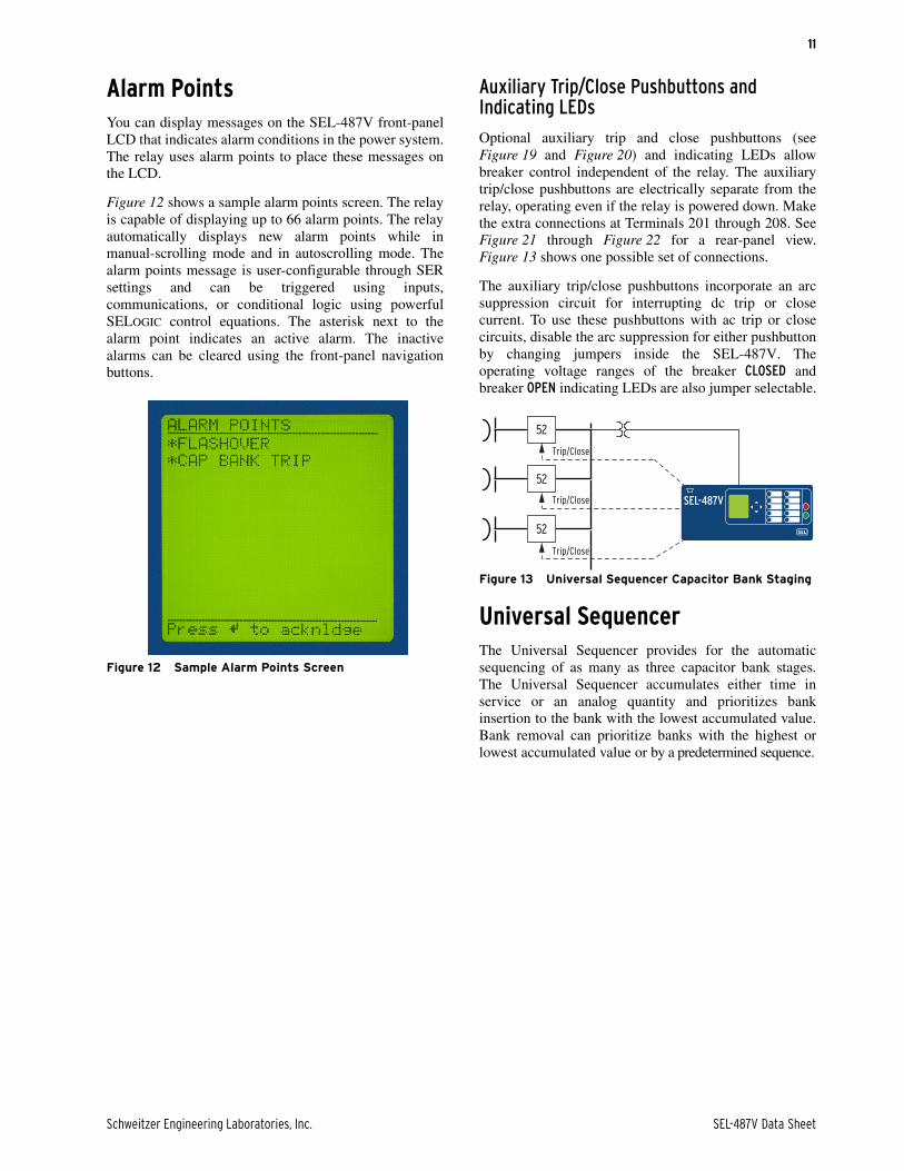
Alarm PointsYou can display messages on the SEL-487V front-panelLCD that indicates alarm conditions in the power system.The relay uses alarm points to place these messages onthe LCD.
Figure 12 shows a sample alarm points screen. The relayis capable of displaying up to 66 alarm points. The relayautomatically displays new alarm points while inmanual-scrolling mode and in autoscrolling mode. Thealarm points message is user-configurable through SERsettings and can be triggered using inputs,communications, or conditional logic using powerfulSELOGIC control equations. The asterisk next to thealarm point indicates an active alarm. The inactivealarms can be cleared using the front-panel navigationbuttons.
Figure 12 Sample Alarm Points Screen
Auxiliary Trip/Close Pushbuttons and Indicating LEDs
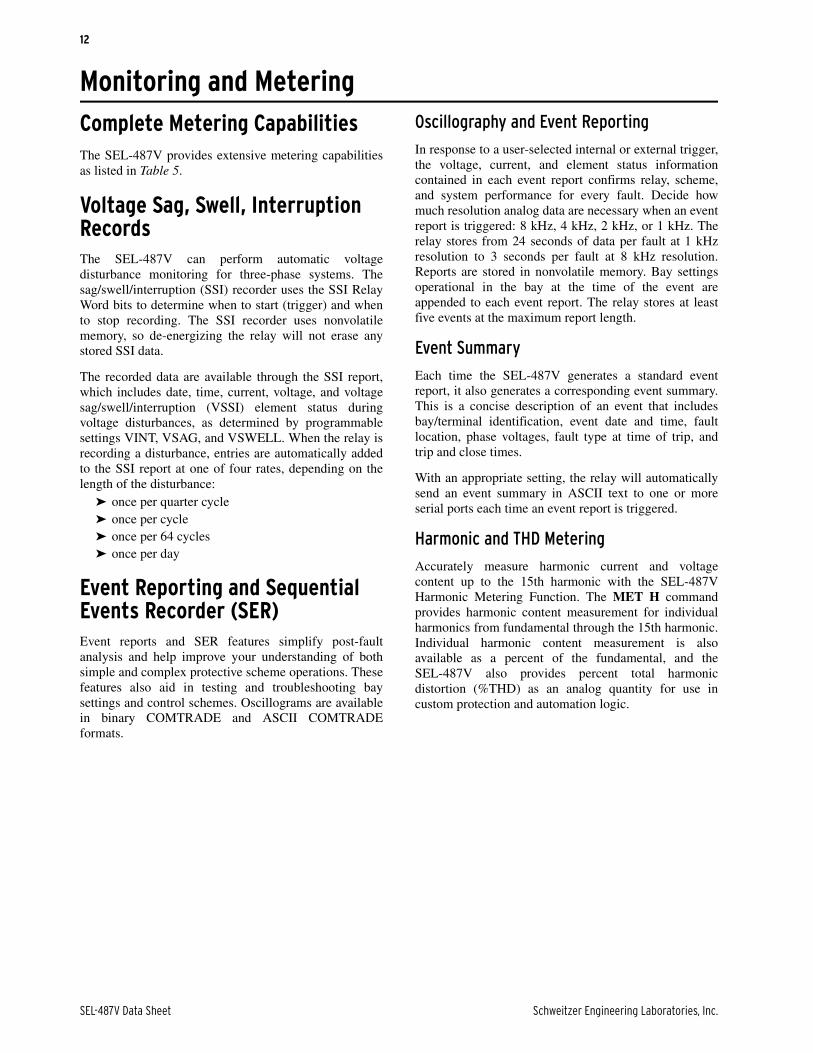
Optional auxiliary trip and close pushbuttons (seeFigure 19 and Figure 20) and indicating LEDs allowbreaker control independent of the relay. The auxiliarytrip/close pushbuttons are electrically separate from therelay, operating even if the relay is powered down. Makethe extra connections at Terminals 201 through 208. SeeFigure 21 through Figure 22 for a rear-panel view.Figure 13 shows one possible set of connections.
The auxiliary trip/close pushbuttons incorporate an arcsuppression circuit for interrupting dc trip or closecurrent. To use these pushbuttons with ac trip or closecircuits, disable the arc suppression for either pushbuttonby changing jumpers inside the SEL-487V. Theoperating voltage ranges of the breaker CLOSED andbreaker OPEN indicating LEDs are also jumper selectable.
Figure 13 Universal Sequencer Capacitor Bank Staging
Universal SequencerThe Universal Sequencer provides for the automaticsequencing of as many as three capacitor bank stages.The Universal Sequencer accumulates either time inservice or an analog quantity and prioritizes bankinsertion to the bank with the lowest accumulated value.Bank removal can prioritize banks with the highest orlowest accumulated value or by a predetermined sequence.
Trip/Close
Trip/Close
Trip/Close
52
52
52
SEL-487V
SEL-487V Data Sheet Schweitzer Engineering Laboratories, Inc.
12
Monitoring and MeteringComplete Metering CapabilitiesThe SEL-487V provides extensive metering capabilitiesas listed in Table 5.
Voltage Sag, Swell, Interruption RecordsThe SEL-487V can perform automatic voltagedisturbance monitoring for three-phase systems. Thesag/swell/interruption (SSI) recorder uses the SSI RelayWord bits to determine when to start (trigger) and whento stop recording. The SSI recorder uses nonvolatilememory, so de-energizing the relay will not erase anystored SSI data.
The recorded data are available through the SSI report,which includes date, time, current, voltage, and voltagesag/swell/interruption (VSSI) element status duringvoltage disturbances, as determined by programmablesettings VINT, VSAG, and VSWELL. When the relay isrecording a disturbance, entries are automatically addedto the SSI report at one of four rates, depending on thelength of the disturbance:
➤ once per quarter cycle➤ once per cycle➤ once per 64 cycles➤ once per day
Event Reporting and Sequential Events Recorder (SER)Event reports and SER features simplify post-faultanalysis and help improve your understanding of bothsimple and complex protective scheme operations. Thesefeatures also aid in testing and troubleshooting baysettings and control schemes. Oscillograms are availablein binary COMTRADE and ASCII COMTRADEformats.
Oscillography and Event Reporting
In response to a user-selected internal or external trigger,the voltage, current, and element status informationcontained in each event report confirms relay, scheme,and system performance for every fault. Decide howmuch resolution analog data are necessary when an eventreport is triggered: 8 kHz, 4 kHz, 2 kHz, or 1 kHz. Therelay stores from 24 seconds of data per fault at 1 kHzresolution to 3 seconds per fault at 8 kHz resolution.Reports are stored in nonvolatile memory. Bay settingsoperational in the bay at the time of the event areappended to each event report. The relay stores at leastfive events at the maximum report length.
Event Summary
Each time the SEL-487V generates a standard eventreport, it also generates a corresponding event summary.This is a concise description of an event that includesbay/terminal identification, event date and time, faultlocation, phase voltages, fault type at time of trip, andtrip and close times.
With an appropriate setting, the relay will automaticallysend an event summary in ASCII text to one or moreserial ports each time an event report is triggered.
Harmonic and THD Metering
Accurately measure harmonic current and voltagecontent up to the 15th harmonic with the SEL-487VHarmonic Metering Function. The MET H commandprovides harmonic content measurement for individualharmonics from fundamental through the 15th harmonic.Individual harmonic content measurement is alsoavailable as a percent of the fundamental, and theSEL-487V also provides percent total harmonicdistortion (%THD) as an analog quantity for use incustom protection and automation logic.

Schweitzer Engineering Laboratories, Inc. SEL-487V Data Sheet
13
=>>MET H <Enter>
Relay 1 Date: 03/17/2013 Time: 12:39:56.328Station A Serial Number: 1120820717
Magnitudes of Harmonic Inputs (Amps Sec, Volt Sec) H IAW IBW ICW IAX IBX ICX VAY VBY VCY VAZ VBZ VCZ 1 1.00 1.00 1.00 0.00 0.00 0.00 60.00 60.00 60.00 0.00 0.00 0.00 2 0.00 0.00 0.00 0.00 0.00 0.00 0.01 0.00 0.00 0.00 0.00 0.00 3 0.50 0.50 0.50 0.00 0.00 0.00 19.79 19.76 19.81 0.00 0.00 0.00 4 0.00 0.00 0.00 0.00 0.00 0.00 0.00 0.00 0.00 0.00 0.00 0.00 5 0.50 0.50 0.50 0.00 0.00 0.00 19.75 19.73 19.76 0.00 0.00 0.00 6 0.00 0.00 0.00 0.00 0.00 0.00 0.00 0.00 0.00 0.00 0.00 0.00 7 0.00 0.00 0.00 0.00 0.00 0.00 0.00 0.00 0.00 0.00 0.00 0.00 8 0.00 0.00 0.00 0.00 0.00 0.00 0.00 0.00 0.00 0.00 0.00 0.00 9 0.00 0.00 0.00 0.00 0.00 0.00 0.00 0.00 0.00 0.00 0.00 0.0010 0.00 0.00 0.00 0.00 0.00 0.00 0.01 0.00 0.00 0.00 0.00 0.0011 0.00 0.00 0.00 0.00 0.00 0.00 0.01 0.00 0.00 0.00 0.00 0.0012 0.00 0.00 0.00 0.00 0.00 0.00 0.00 0.00 0.00 0.00 0.00 0.0013 0.00 0.00 0.00 0.00 0.00 0.00 0.00 0.00 0.00 0.00 0.00 0.0014 0.00 0.00 0.00 0.00 0.00 0.00 0.00 0.00 0.00 0.00 0.00 0.0015 0.00 0.00 0.00 0.00 0.00 0.00 0.00 0.00 0.00 0.00 0.00 0.00
FREQ (Hz) 60.000 Frequency Tracking = Y
Sequential Events Recorder (SER)
This feature provides a broad perspective of relayelement operation. Items that trigger an SER entry areselectable and can include input/output change of state,element pickup/dropout, recloser state changes, etc. Therelay SER stores the latest 1,000 entries.
Analog Signal ProfilingThe SEL-487V provides analog signal profiling for up to20 analog quantities. Any analog quantity measured orcalculated by the SEL-487V can be selected for analogsignal profiling. Signal sampling rates of 1, 5, 15, 30, and60 minutes can be selected through settings. The analogsignal profile report provides a comma-separatedvariable (CSV) list that can be loaded into anyspreadsheet or database for analysis and graphicaldisplay.
SELOGIC enable/disable functions can start and stopsignal profiling based on Boolean or analog comparisonconditions.
High-Accuracy TimekeepingWith a combination of IRIG-B and a global positioningsatellite, the SEL-487V time-tags oscillography to within10 µs accuracy. This high accuracy can be combined withthe high sampling rate of the relay to synchronize datafrom across the system with an accuracy of better than1/4 electrical degree. This allows examination of thepower system state at given times, including load angles,system swings, and other system-wide events. Triggeringcan be via external signal (contact or communicationsport), set time, or system event. Optimal calibration ofthis feature requires a knowledge of primary inputcomponent (VT and CT) phase delay and error.
A single IRIG-B time-code input synchronizes theSEL-487V time to within ±1 ms of the time-source input.A convenient source for this time code is the SEL-2032Communications Processor (via Serial Port 1 on theSEL-487V).
SNTP Time SynchronizationUse simple network time protocol (SNTP) to cost-effectively synchronize SEL-487V relays equipped withEthernet communication to as little as ±5 ms overstandard Ethernet networks. Use SNTP as a primary timesource, or as a backup to a higher accuracy IRIG-B timeinput to the relay.
Figure 14 SNTP Diagram
Substation Battery Monitor for DC Quality AssuranceThe SEL-487V measures and reports the substationbattery voltage. Programmable threshold comparatorsand associated logic provide alarm and control ofbatteries and charger. The relay also provides batterysystem ground detection. Monitor these thresholds withan SEL communications processor and trigger messages,telephone calls, or other actions.
The measured dc voltage is reported in the METERdisplay via serial port communications, on the LCD, andin the event report. The event report data provides an

SEL-487V Data Sheet Schweitzer Engineering Laboratories, Inc.
14
oscillographic display of the battery voltage. Monitor thesubstation battery voltage drops during trip, close, andother control operations.
Breaker Monitor Feature Allows for Wear-Based Breaker Mainte-nance SchedulingCircuit breakers experience mechanical and electricalwear at each operation. Effective scheduling of breakermaintenance takes into account the manufacturer’spublished data of contact wear versus interruption levelsand operation count. The SEL-487V breaker monitorfeature compares the breaker manufacturer’s publisheddata to the integrated actual interrupted current andnumber of operations.
➤ Every time the breaker trips, the relay integratesinterrupted current. When the result of this integra-tion exceeds the threshold set by the breaker wearcurve (Figure 15), the bay can alarm via an outputcontact or the optional front-panel display. Withthis information, you can schedule breaker mainte-nance in a timely, economical fashion.
➤ Monitor last an average mechanical and electricalinterruption time per pole. You can easily deter-mine if operating time is increasing beyond reason-able tolerance to schedule proactive breakermaintenance. You can activate an alarm point ifoperation time goes beyond a preset value.
➤ Breaker motor run time and breaker inactivity arealso recorded for each breaker operation.
Figure 15 Breaker Contact Wear Curve and Settings
AutomationFlexible Control Logic and Integration FeaturesSEL-487V control logic:
➤ Replaces traditional panel control switches➤ Eliminates RTU-to-bay wiring➤ Replaces traditional latching relays➤ Replaces traditional indicating panel lights➤ Performs real-time control using synchrophasor data
Eliminate traditional panel control switches with 32 localcontrol points. Set, clear, or pulse local control pointswith the front-panel pushbuttons and display. Programthe local control points to implement your controlscheme via SELOGIC control equations. The local controlpoints provide functions such as trip testing,enabling/disabling reclosing, and tripping/closing circuitbreakers.
kA Interrupted
(Set Point 1)
(Set Point 2)
(Set Point 3)
Breaker Manufacturer'sMaintenance Curve
Clo
se t
o O
pen
Ope
rati
ons
Table 5 Metering Capabilities
Capabilities Description
Instantaneous Quantities
Voltages VA, B, C (Y), VA, B, C (Z), V, 3V0, V1, 3V2
0–300 V with phase quantities for each of the six voltage sources available as a sepa-rate quantity.
Currents IA,B,C (W), IA,B,C (X)IAL, IBL, ICL (combined currents)IGL, I1L, 3I2L (combined currents)
Phase quantities for each of the two current sources available as a separate quantity or combined as line quantities.
Power/Energy Metering Quantities
MW, MWh, MVAR, MVARh, MVA, PF,single-phase, and three-phase
Available for each input set and as combined quantities for the line.
Demand/Peak Metering
IA,B,C, 3I2, 3I0 Thermal or rolling interval demand and peak demand.
MW, MVAR, MVA, single-phase Thermal or rolling interval demand and peak demand.
MW, MVAR, MVA, three-phase Thermal or rolling interval demand and peak demand.
Schweitzer Engineering Laboratories, Inc. SEL-487V Data Sheet
15
Eliminate RTU-to-bay wiring with 32 remote controlpoints. Set, clear, or pulse remote control points via serialport commands. Incorporate the remote control pointsinto your control scheme via SELOGIC control equations.Remote control points can be applied to SCADA-typecontrol operations (e.g., trip, close, settings group selection).
Replace traditional latching relays for such functions asremote control enable with 32 latching control points.Program latch set and latch reset conditions withSELOGIC control equations. Set or reset the latch controlpoints via control inputs, remote control points, localcontrol points, or any programmable logic condition. Thelatch control points retain states when the relay losespower.
Replace traditional indicating panel lights and switcheswith 24 latching target LEDs and 12 programmablepushbuttons with LEDs. Define custom messages (i.e.,BREAKER OPEN, BREAKER CLOSED, CONTROL
ENABLED) to report power system or relay conditionson the large format LCD. Control which messages aredisplayed via SELOGIC control equations by driving theLCD display via any logic point in the relay.
Perform real-time control logic using synchrophasor databy using local or remote synchrophasor data that isavailable as analog quantities to SELOGIC. Localsynchrophasor data provided by the host relay, or remotedata received as C37.118 serial data are accessible.Voltage and current magnitudes and angles, frequency,and rate-of-change of frequency (df/dt) are provided.
Open Communications Protocols
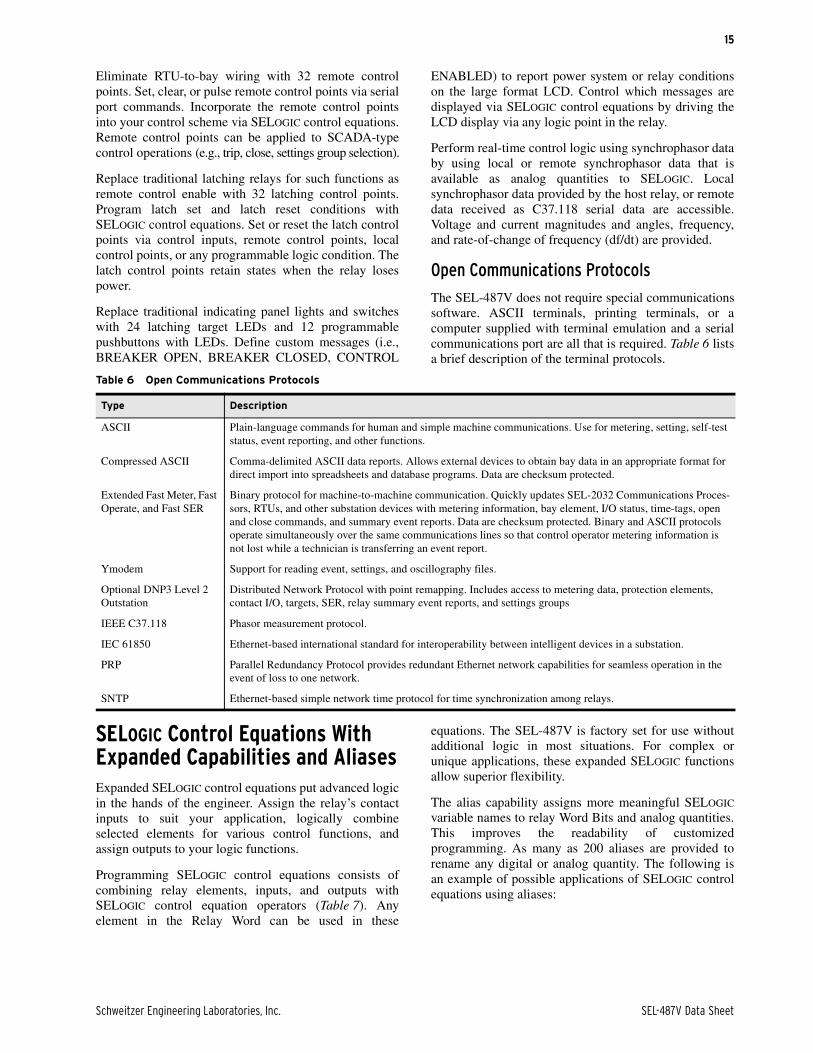
The SEL-487V does not require special communicationssoftware. ASCII terminals, printing terminals, or acomputer supplied with terminal emulation and a serialcommunications port are all that is required. Table 6 listsa brief description of the terminal protocols.
SELOGIC Control Equations With Expanded Capabilities and AliasesExpanded SELOGIC control equations put advanced logicin the hands of the engineer. Assign the relay’s contactinputs to suit your application, logically combineselected elements for various control functions, andassign outputs to your logic functions.
Programming SELOGIC control equations consists ofcombining relay elements, inputs, and outputs withSELOGIC control equation operators (Table 7). Anyelement in the Relay Word can be used in these
equations. The SEL-487V is factory set for use withoutadditional logic in most situations. For complex orunique applications, these expanded SELOGIC functionsallow superior flexibility.
The alias capability assigns more meaningful SELOGIC
variable names to relay Word Bits and analog quantities.This improves the readability of customizedprogramming. As many as 200 aliases are provided torename any digital or analog quantity. The following isan example of possible applications of SELOGIC controlequations using aliases:
Table 6 Open Communications Protocols
Type Description
ASCII Plain-language commands for human and simple machine communications. Use for metering, setting, self-test status, event reporting, and other functions.
Compressed ASCII Comma-delimited ASCII data reports. Allows external devices to obtain bay data in an appropriate format for direct import into spreadsheets and database programs. Data are checksum protected.
Extended Fast Meter, Fast Operate, and Fast SER
Binary protocol for machine-to-machine communication. Quickly updates SEL-2032 Communications Proces-sors, RTUs, and other substation devices with metering information, bay element, I/O status, time-tags, open and close commands, and summary event reports. Data are checksum protected. Binary and ASCII protocols operate simultaneously over the same communications lines so that control operator metering information is not lost while a technician is transferring an event report.
Ymodem Support for reading event, settings, and oscillography files.
Optional DNP3 Level 2 Outstation
Distributed Network Protocol with point remapping. Includes access to metering data, protection elements, contact I/O, targets, SER, relay summary event reports, and settings groups
IEEE C37.118 Phasor measurement protocol.
IEC 61850 Ethernet-based international standard for interoperability between intelligent devices in a substation.
PRP Parallel Redundancy Protocol provides redundant Ethernet network capabilities for seamless operation in the event of loss to one network.
SNTP Ethernet-based simple network time protocol for time synchronization among relays.
SEL-487V Data Sheet Schweitzer Engineering Laboratories, Inc.
16
=>>SET T <Enter>1: PMV01,THETA
(assign the alias “THETA” to math variable PMV01)2: PMV02,TAN
(assign the alias “TAN” to math variable PMV02)=>>SET L <Enter>1: # CALCULATE THE TANGENT OF THETA2: TAN:=SIN(THETA)/COS(THETA)
(use the aliases in an equation)
Add programmable control functions to your relay andautomation systems. New functions and capabilitiesenable using analog values in conditional logic
statements. The following are examples of possibleapplications of SELOGIC control equations withexpanded capabilities.
➤ Scale analog values for SCADA retrieval.➤ Initiate remedial action sequence based on load
flow before fault conditions.➤ Interlock breakers and disconnect switches.➤ Restrict breaker tripping in excessive duty situa-
tions without additional relays.➤ Construct a compensated overvoltage element for
open line overvoltage protection.➤ Hold momentary change-of-state conditions for
SCADA polling.➤ Provide a combination of frequency or rate-of-
change frequency functions.
Relay-to-Relay Digital Communication (MIRRORED BITS)The SEL patented MIRRORED BITS technology providesbidirectional relay-to-relay digital communication(Figure 16). In the SEL-487V, MIRRORED BITS canoperate simultaneously on any two serial ports for three-terminal power system operation.
This bidirectional digital communication createsadditional outputs (transmitted MIRRORED BITS) andadditional inputs (received MIRRORED BITS) for eachserial port operating in the MIRRORED BITS
communications mode. Communicated information caninclude digital, analog, and virtual terminal data. Virtualterminal allows the operator access to remote relaysthrough the local relay MIRRORED BITS port. TheseMIRRORED BITS can be used to transfer informationbetween the SEL-487V and other system voltageregulation devices to provide enhanced system voltageand power factor control. The dual-port MIRRORED BITS
communications are capable of high-speedcommunications-assisted schemes for the protection andcontrol of capacitor bank applications.
CommunicationThe SEL-487V offers the following serialcommunication features:
➤ Four independent EIA-232 serial ports.➤ Full access to event history, relay status, and meter
information.➤ Strong password protection for settings and group
switching.➤ DNP3 Level 2 Server.➤ Patented SEL Fast Message interleaving of ASCII
and binary data for SCADA communications,including access to SER, relay element targets,event data, and more.
➤ Communication of synchronized phasor measure-ment data using either SEL Fast Messaging forSynchrophasors or IEEE C37.118-2005 Standardfor Synchrophasors for Power Systems.
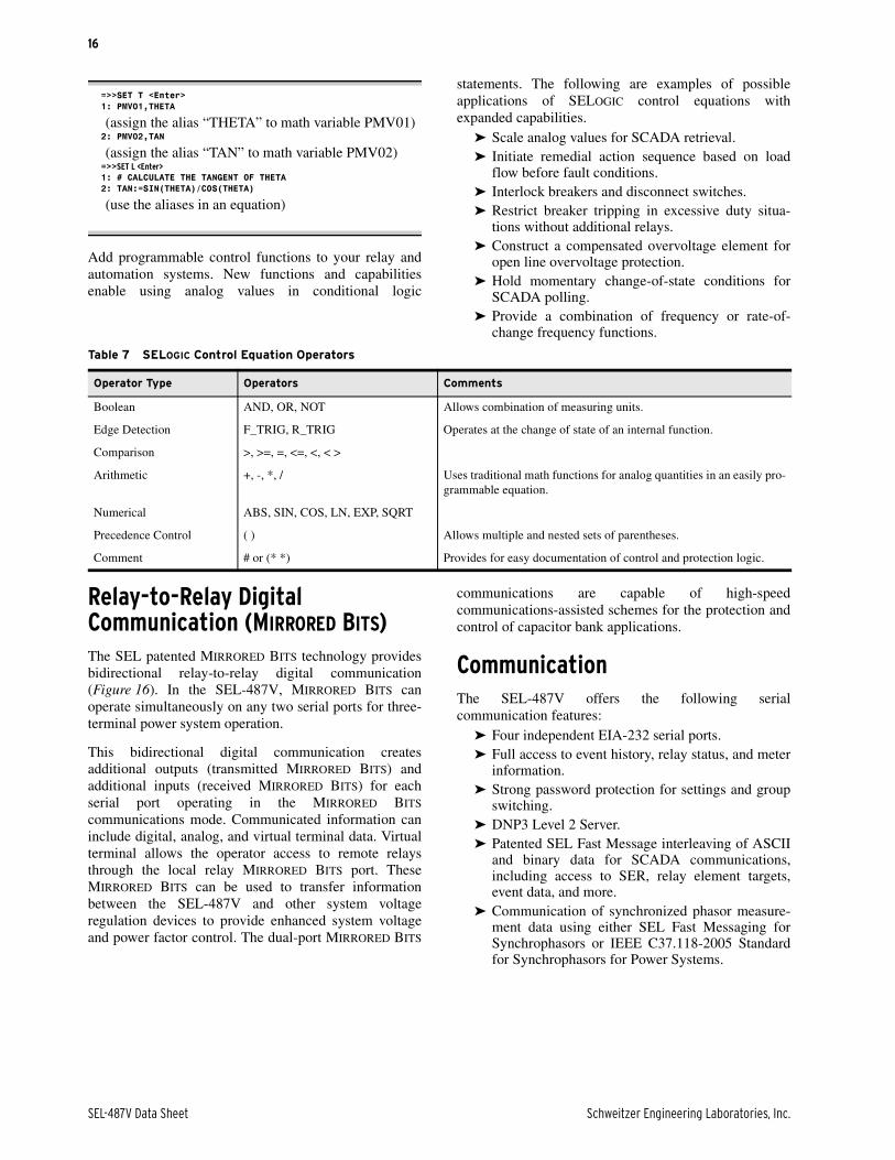
Table 7 SELOGIC Control Equation Operators
Operator Type Operators Comments
Boolean AND, OR, NOT Allows combination of measuring units.
Edge Detection F_TRIG, R_TRIG Operates at the change of state of an internal function.
Comparison >, >=, =, <=, <, < >
Arithmetic +, -, *, / Uses traditional math functions for analog quantities in an easily pro-grammable equation.
Numerical ABS, SIN, COS, LN, EXP, SQRT
Precedence Control ( ) Allows multiple and nested sets of parentheses.
Comment # or (* *) Provides for easy documentation of control and protection logic.
Schweitzer Engineering Laboratories, Inc. SEL-487V Data Sheet
17
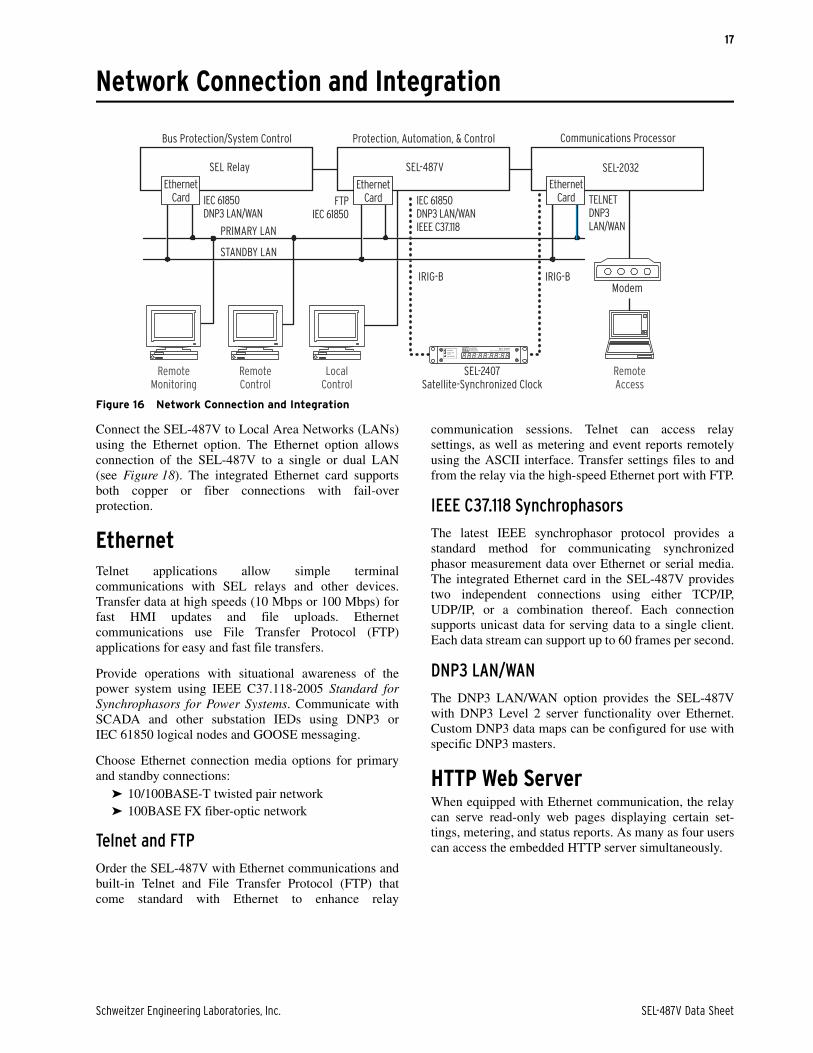
Network Connection and Integration
Figure 16 Network Connection and Integration
Connect the SEL-487V to Local Area Networks (LANs)using the Ethernet option. The Ethernet option allowsconnection of the SEL-487V to a single or dual LAN(see Figure 18). The integrated Ethernet card supportsboth copper or fiber connections with fail-overprotection.
Ethernet Telnet applications allow simple terminalcommunications with SEL relays and other devices.Transfer data at high speeds (10 Mbps or 100 Mbps) forfast HMI updates and file uploads. Ethernetcommunications use File Transfer Protocol (FTP)applications for easy and fast file transfers.
Provide operations with situational awareness of thepower system using IEEE C37.118-2005 Standard forSynchrophasors for Power Systems. Communicate withSCADA and other substation IEDs using DNP3 orIEC 61850 logical nodes and GOOSE messaging.
Choose Ethernet connection media options for primaryand standby connections:
➤ 10/100BASE-T twisted pair network➤ 100BASE FX fiber-optic network
Telnet and FTP
Order the SEL-487V with Ethernet communications andbuilt-in Telnet and File Transfer Protocol (FTP) thatcome standard with Ethernet to enhance relay
communication sessions. Telnet can access relaysettings, as well as metering and event reports remotelyusing the ASCII interface. Transfer settings files to andfrom the relay via the high-speed Ethernet port with FTP.
IEEE C37.118 Synchrophasors
The latest IEEE synchrophasor protocol provides astandard method for communicating synchronizedphasor measurement data over Ethernet or serial media.The integrated Ethernet card in the SEL-487V providestwo independent connections using either TCP/IP,UDP/IP, or a combination thereof. Each connectionsupports unicast data for serving data to a single client.Each data stream can support up to 60 frames per second.
DNP3 LAN/WAN
The DNP3 LAN/WAN option provides the SEL-487Vwith DNP3 Level 2 server functionality over Ethernet.Custom DNP3 data maps can be configured for use withspecific DNP3 masters.
HTTP Web ServerWhen equipped with Ethernet communication, the relaycan serve read-only web pages displaying certain set-tings, metering, and status reports. As many as four userscan access the embedded HTTP server simultaneously.
Protection, Automation, & Control
STANDBY LAN
PRIMARY LAN
Modem
RemoteAccess
IRIG-BIRIG-B
Bus Protection/System Control
EthernetCard
EthernetCard
EthernetCard
RemoteMonitoring
RemoteControl
LocalControl
Communications Processor
SEL-2032SEL-487VSEL Relay
SEL-2407Satellite-Synchronized Clock
TELNETDNP3LAN/WAN
FTPIEC 61850
IEC 61850DNP3 LAN/WAN
IEC 61850DNP3 LAN/WANIEEE C37.118

SEL-487V Data Sheet Schweitzer Engineering Laboratories, Inc.
18
Figure 17 SEL-487V HTTP Web Server Settings Screen
IEC 61850 Ethernet CommunicationsIEC 61850 Ethernet-based communications provideinteroperability between intelligent devices within thesubstation. Logical nodes using IEC 61850 allowstandardized interconnection of intelligent devices fromdifferent manufacturers for monitoring and control of thesubstation. Reduce wiring between variousmanufacturers’ devices and simplify operating logic withIEC 61850. Eliminate system RTUs by streamingmonitoring and control information from the intelligentdevices directly to remote SCADA client devices.
The SEL-487V can be ordered with embeddedIEC 61850 protocol operating on 10/100 Mbps Ethernet.IEC 61850 Ethernet protocol provides relay monitoringand control functions including:
➤ As many as 24 incoming GOOSE messages. Theincoming GOOSE messages can be used to controlup to 50 control bits in the relay with <3 mslatency from device to device. These messagesprovide binary control inputs and analog values tothe relay for high-speed control functions andmonitoring.
➤ As many as eight outgoing GOOSE messages.Outgoing GOOSE messages can be configured forBoolean or analog data. Boolean data and desig-nated remote analog outputs are provided with<3 ms latency from device to device. Apply outgo-ing GOOSE messages for high-speed control andmonitoring of external breakers, switches, andother devices.
➤ IEC 61850 Data Server. The SEL-487V, equippedwith embedded IEC 61850 Ethernet protocol, pro-vides data according to predefined logical nodeobjects. As many as six simultaneous client associ-ations are supported by each relay. Relevant RelayWord bits are available within the logical nodedata, so status of relay elements, inputs, outputs, orSELOGIC equations can be monitored using theIEC 61850 data server provided in the relay.
ACSELERATOR Architect® SEL-5032 Software managesthe logical node data for all IEC 68150 devices on thenetwork. This Microsoft® Windows®-based softwareprovides easy-to-use displays for identifying and bindingIEC 61850 network data between logical nodes usingIEC 61850 compliant Configured IED Description (CID)files. CID files are used by ACSELERATOR Architect todescribe the data that will be provided by the IEC 61850logical node within each relay.
Custom Control CapabilitiesCustomize control capabilities, adding stability andsecurity to your system.
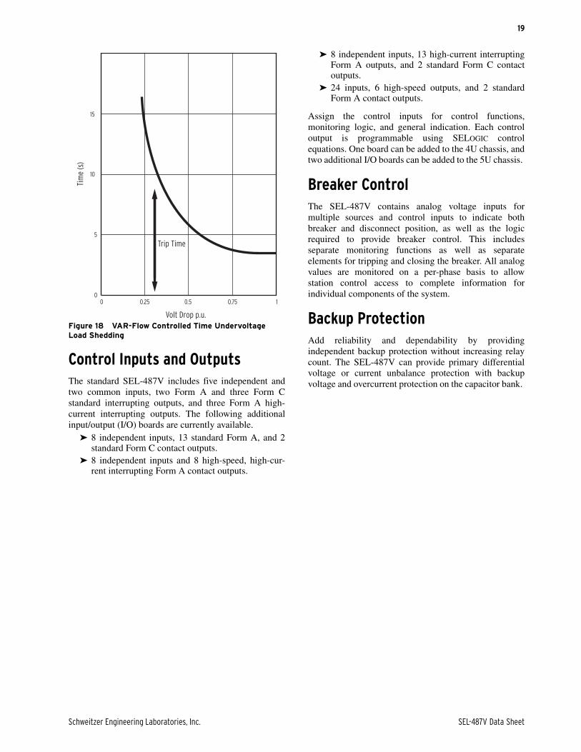
Expanded SELOGIC control equations can createadvanced stability enhancements such as VAR-flowcontrolled time undervoltage load shedding.
Combine frequency elements with voltage supervisionfor added security with underfrequency load-sheddingsystems.
Schweitzer Engineering Laboratories, Inc. SEL-487V Data Sheet
19
Figure 18 VAR-Flow Controlled Time Undervoltage Load Shedding
Control Inputs and OutputsThe standard SEL-487V includes five independent andtwo common inputs, two Form A and three Form Cstandard interrupting outputs, and three Form A high-current interrupting outputs. The following additionalinput/output (I/O) boards are currently available.
➤ 8 independent inputs, 13 standard Form A, and 2standard Form C contact outputs.
➤ 8 independent inputs and 8 high-speed, high-cur-rent interrupting Form A contact outputs.
➤ 8 independent inputs, 13 high-current interruptingForm A outputs, and 2 standard Form C contactoutputs.
➤ 24 inputs, 6 high-speed outputs, and 2 standardForm A contact outputs.
Assign the control inputs for control functions,monitoring logic, and general indication. Each controloutput is programmable using SELOGIC controlequations. One board can be added to the 4U chassis, andtwo additional I/O boards can be added to the 5U chassis.
Breaker ControlThe SEL-487V contains analog voltage inputs formultiple sources and control inputs to indicate bothbreaker and disconnect position, as well as the logicrequired to provide breaker control. This includesseparate monitoring functions as well as separateelements for tripping and closing the breaker. All analogvalues are monitored on a per-phase basis to allowstation control access to complete information forindividual components of the system.
Backup ProtectionAdd reliability and dependability by providingindependent backup protection without increasing relaycount. The SEL-487V can provide primary differentialvoltage or current unbalance protection with backupvoltage and overcurrent protection on the capacitor bank.
Volt Drop p.u.
Trip Time
Tim
e (s
)
15
10
5
00 0.50.25 0.75 1
SEL-487V Data Sheet Schweitzer Engineering Laboratories, Inc.
20
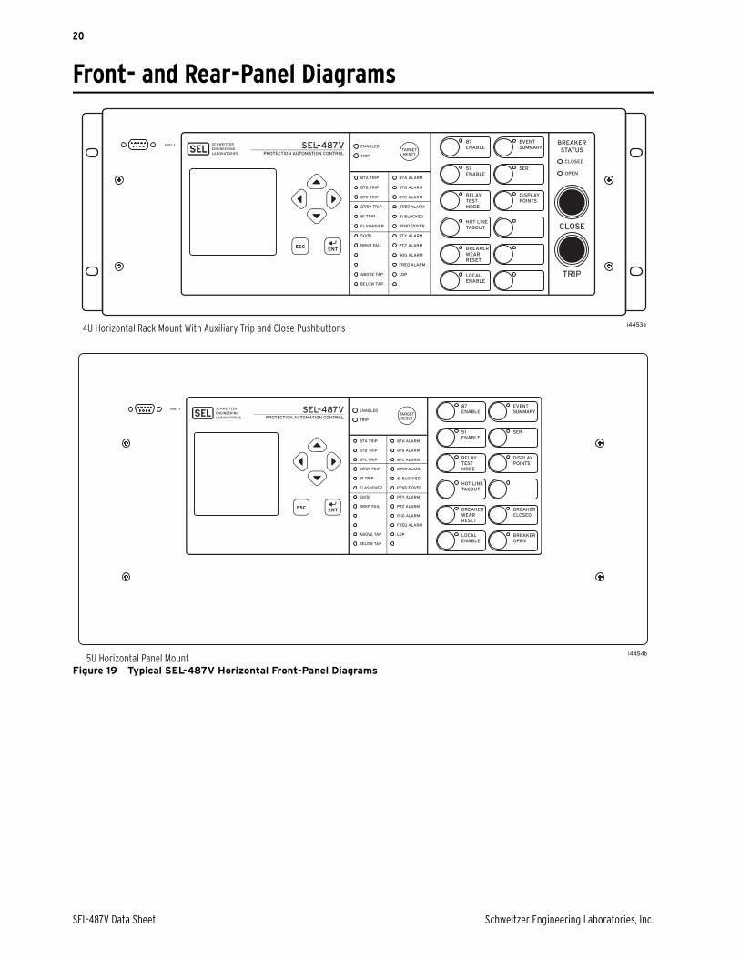
Front- and Rear-Panel Diagrams
Figure 19 Typical SEL-487V Horizontal Front-Panel Diagrams
i4453a
i4454b
4U Horizontal Rack Mount With Auxiliary Trip and Close Pushbuttons
5U Horizontal Panel Mount
Schweitzer Engineering Laboratories, Inc. SEL-487V Data Sheet
21
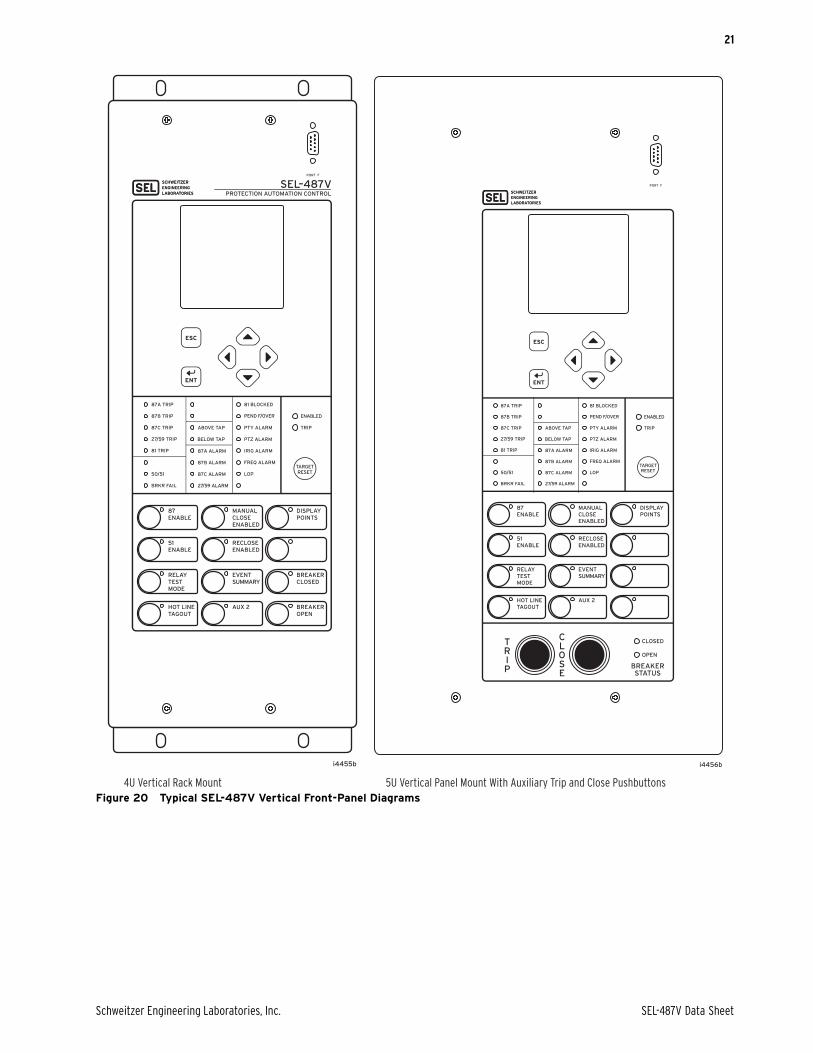
Figure 20 Typical SEL-487V Vertical Front-Panel Diagrams4U Vertical Rack Mount 5U Vertical Panel Mount With Auxiliary Trip and Close Pushbuttons
i4455b i4456b
SEL-487V Data Sheet Schweitzer Engineering Laboratories, Inc.
22
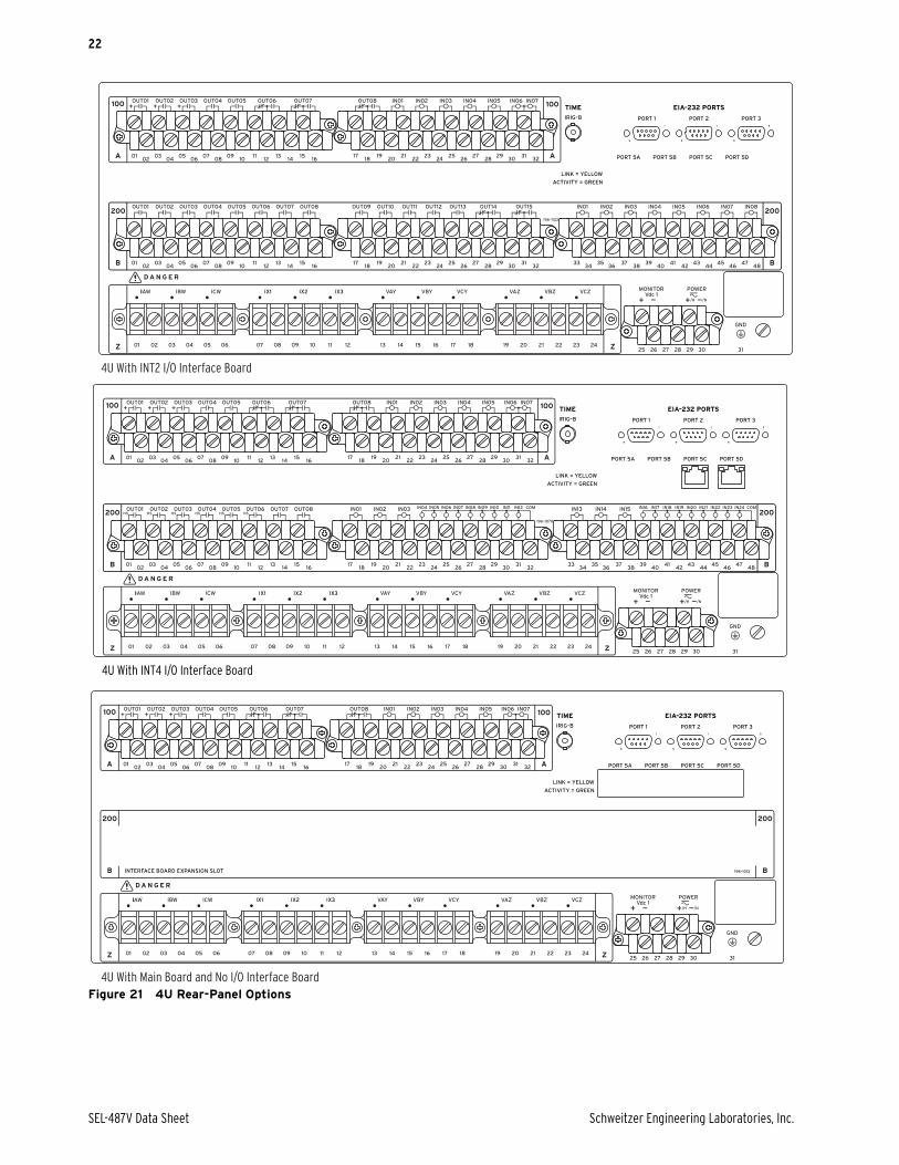
Figure 21 4U Rear-Panel Options
4U With INT2 I/O Interface Board
4U With Main Board and No I/O Interface Board
4U With INT4 I/O Interface Board

Schweitzer Engineering Laboratories, Inc. SEL-487V Data Sheet
23
Figure 22 5U Connectorized With INT3 and INT8 Interface Boards and Ethernet Option
Relay Dimensions
Figure 23 SEL-487V Dimensions for Rack- and Panel-Mount Models (Horizontal Mounting Shown; Dimensions Also Apply to Vertical Mounting)
5U Connectorized, With INT3 and INT8 Interface Boards and Ethernet Option
SEL-487V Data Sheet Schweitzer Engineering Laboratories, Inc.
24
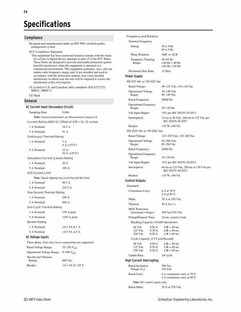
SpecificationsInstruction Manual
ComplianceDesigned and manufactured under an ISO 9001 certified quality
management system
FCC Compliance StatementThis equipment has been tested and found to comply with the limits
for a Class A digital device, pursuant to part 15 of the FCC Rules. These limits are designed to provide reasonable protection against harmful interference when the equipment is operated in a commercial environment. This equipment generates, uses, and can radiate radio frequency energy and, if not installed and used in accordance with the instruction manual, may cause harmful interference in which case the user will be required to correct the interference at his own expense.
UL Listed to U.S. and Canadian safety standards (File E212775; NRGU, NRGU7)
CE Mark
GeneralAC Current Input (Secondary Circuit)
Sampling Rate: 8 kHz
Note: Current transformers are Measurement Category II.
Current Rating (With DC Offset at X/R = 10, 1.5 cycles)
1 A Nominal: 18.2 A
5 A Nominal: 91 A
Continuous Thermal Rating
1 A Nominal: 3 A4 A (+55°C)
5 A Nominal: 15 A20 A (+55°C)
Saturation Current (Linear) Rating
1 A Nominal: 20 A
5 A Nominal: 100 A
A/D Current Limit
Note: Signal clipping may occur beyond this limit.
1 A Nominal: 49.5 A
5 A Nominal: 247.5 A
One-Second Thermal Rating
1 A Nominal: 100 A
5 A Nominal: 500 A
One-Cycle Thermal Rating
1 A Nominal: 250 A peak
5 A Nominal: 1250 A peak
Burden Rating
1 A Nominal: 0.1 VA at 1 A
5 A Nominal: 0.5 VA at 5 A
AC Voltage Inputs
Three-phase, four-wire (wye) connections are supported.
Rated Voltage Range: 55–250 VLN
Operational Voltage Range: 0–300 VLN
Ten-Second Thermal Rating: 600 Vac
Burden: 0.1 VA @ 125 V
Frequency and Rotation
Nominal Frequency
Rating: 50 ± 5 Hz 60 ± 5 Hz
Phase Rotation: ABC or ACB
Frequency Tracking Range:
40–65 Hz<40 Hz = 40 Hz>65 Hz = 65 Hz
Maximum Slew Rate: 15 Hz/s
Power Supply
48–125 Vdc or 110–120 Vac
Rated Voltage: 48–125 Vdc, 110–120 Vac
Operational Voltage Range:
38–140 Vdc85–140 Vac
Rated Frequency: 50/60 Hz
Operational Frequency Range: 30–120 Hz
Vdc Input Ripple: 15% per IEC 60255-26:2013
Interruption: 14 ms at 48 Vdc, 160 ms at 125 Vdc per IEC 60255-26:2013
Burden: <35 W, <90 VA
125–250 Vdc or 110–240 Vac
Rated Voltage: 125–250 Vdc, 110–240 Vac
Operational Voltage Range:
85–300 Vdc85–264 Vac
Rated Frequency: 50/60 Hz
Operational Frequency Range: 30–120 Hz
Vdc Input Ripple: 15% per IEC 60255-26:2013
Interruption: 46 ms at 125 Vdc, 250 ms at 250 Vdc per IEC 60255-26:2013
Burden: <35 W, <90 VA
Control Outputs
Standard
Continuous Carry: 6 A at 70°C4 A at 85°C
Make: 30 A at 250 Vdc
Thermal: 50 A for 1 s
MOV Protection (maximum voltage): 250 Vac/330 Vdc
Pickup/Dropout Time: 6 ms, resistive load
Breaking Capacity (10,000 Operations):
48 Vdc 0.50 A L/R = 40 ms125 Vdc 0.30 A L/R = 40 ms250 Vdc 0.20 A L/R = 40 ms
Cyclic Capacity (2.5 Cycle/Second):
48 Vdc 0.50 A L/R = 40 ms125 Vdc 0.30 A L/R = 40 ms250 Vdc 0.20 A L/R = 40 ms
Update Rate: 1/8 cycle
High-Current Interrupting
Rated Insulation Voltage (Ui):
300 Vac470 Vdc
Rated Carry: 6 A continuous carry at 70°C4 A continuous carry at 85°C
Note: DC control signals only.
Rated Make: 30 A at 250 Vdc

Schweitzer Engineering Laboratories, Inc. SEL-487V Data Sheet
25
Thermal Rating: 50 A for 1 s
MOV Protection (Maximum Voltage): 330 Vdc
Pickup/Dropout Time: 6 ms, resistive load
Inductive Breaking Capacity (10,000 Operations):
48 Vdc 10 A L/R = 40 ms125 Vdc 10 A L/R = 40 ms250 Vdc 10 A L/R = 20 ms
Cyclic Capacity (4 Cycles in 1 Second, Followed by 2 Minutes Idle for Thermal Dissipation):
48 Vdc 10 A L/R = 40 ms125 Vdc 10 A L/R = 40 ms250 Vdc 10 A L/R = 20 ms
Mechanical Durability: 10,000 no-load operations
High-Speed, High-Current Interrupting
Rated Carry: 6 A continuous carry at 70°C4 A continuous carry at 85°C
Rated Make: 30 A at 250 Vdc
Thermal: 50 A for 1 s
Pickup Time: 10 s, resistive load
Dropout Time: 8 ms, resistive load
Breaking Capacity (10,000 Operations):
48 Vdc 10 A L/R = 40 ms125 Vdc 10 A L/R = 40 ms250 Vdc 10 A L/R = 20 ms
Cyclic Capacity (4 Cycles in 1 Second, Followed by 2 Minutes Idle for Thermal Dissipation):
48 Vdc 10 A L/R = 40 ms125 Vdc 10 A L/R = 40 ms250 Vdc 10 A L/R = 20 ms
Mechanical Durability: 10,000 no-load operations
Minimum Current Rating: 10 mA
Update Rate: 1/8 cycle
Note: Per IEC 60255-23:1994, using the simplified method of assessment
Note: Make rating per IEEE C37.90-2005.Note: Per IEC 61810-1:2005.
Control InputsOptoisolated (Use With AC or DC Signals)
General
Sampling Rate: 2 kHz
Main Board: 5 inputs with no shared terminals2 inputs with shared terminals
INT 2, INT7, and INT8 Interface Boards: 8 inputs with no shared terminals
INT 3 and INT 4: 6 inputs with no shared terminals18 inputs with shared terminals
(2 groups of 9 inputs, with each group sharing one terminal)
Voltage Options: 48, 110, 125, 220, 250 V
DC Thresholds (Dropout Thresholds Indicate Level-Sensitive Option)
48 Vdc Pickup 38.4–60.0 Vdc;Dropout <28.8 Vdc
110 Vdc: Pickup 88.0–132.0 Vdc;Dropout <66.0 Vdc
125 Vdc: Pickup 105–150 Vdc;Dropout <75 Vdc
220 Vdc: Pickup 176–264 Vdc;Dropout <132 Vdc
250 Vdc: Pickup 200–300 Vdc;Dropout <150 Vdc
Current Draw: 5 mA at nominal voltage;8 mA at 110 V option
Rated Frequency: 50 ± 5 Hz, 60 ± 5 Hz
AC Thresholds (Ratings Met Only When Recommended Control Input Settings Are Used—See Table 2.1)
48 Vac: Pickup 32.8–60.0 Vac rms;Dropout <20.3 Vac rms
110 Vac: Pickup 75.1–132.0 Vac rms;Dropout <46.6 Vac rms
125 Vac: Pickup 89.6–150.0 Vac rms;Dropout <53.0 Vac rms
220 Vac: Pickup 150.3–264.0 Vac rms;Dropout <93.2 Vac rms
250 Vac: Pickup 170.6–300.0 Vac rms;Dropout <106 Vac rms
Current Draw: <5 mA at nominal voltage<8 mA at 110 V option
Auxiliary Breaker Control Pushbuttons
Quantity: 2
Pushbutton Functions: One (1) pushbutton shall be provided to open the breaker.
One (1) pushbutton shall be provided to close the breaker.
Resistive DC or AC Outputs With Arc Suppression Disabled:
Make: 30 A
Carry: 6 A continuous carry
1 s Rating: 50 A
MOV Protection (Maximum Voltage): 250 Vac/330 Vdc
Breaking Capacity (10,000 Operations):
48 V 0.50 A L/R = 40 ms125 V 0.30 A L/R = 40 ms250 V 0.20 A L/R = 40 ms
High Interrupt DC Outputs With Arc Suppression Enabled:
Make: 30 A
Carry: 6 A continuous carry
1 s Rating: 50 A
MOV Protection: 330 Vdc/130 J
Breaking Capacity (10,000 Operations):
48 V 10 A L/R = 40 ms125 V 10 A L/R = 40 ms250 V 10 A L/R = 20 ms
Breaker Open/Closed LEDs:
48 Vdc: on for 30–60 Vdc;125 Vdc: on for 80–150 Vdc; 96–144 Vac250 Vdc: on for 150–300 Vdc; 192–288 Vac
Note: With nominal control voltage applied, each LED draws 8 mA (max.). Jumpers may be set to 125 Vdc for 110 Vdc input and set to 250 Vdc for 220 Vdc input.
Note: Per IEC 60255-23:1994, using the simplified method of assessment.
Note: Make rating per IEEE C37.90-2005.Note: Per IEC 61810-2:2005.
Communications Ports
EIA-232: 1 front and 3 rear
Serial Data Speed: 300–57600 bps
Communications Card Slot for Optional Ethernet Card
Ordering Options: 10/100BASE-T
Connector Type: RJ45
Ordering Option: 100BASE-FX Fiber-Optic
Connector Type: LC
Fiber Type: Multimode
SEL-487V Data Sheet Schweitzer Engineering Laboratories, Inc.
26
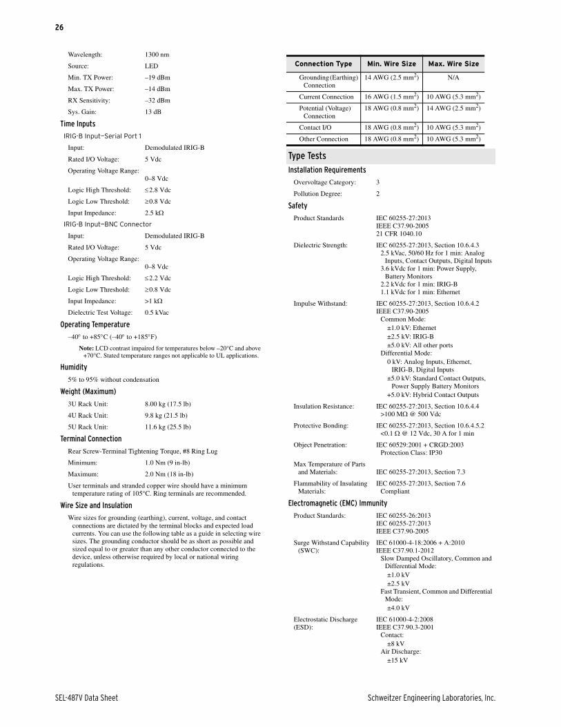
Wavelength: 1300 nm
Source: LED
Min. TX Power: –19 dBm
Max. TX Power: –14 dBm
RX Sensitivity: –32 dBm
Sys. Gain: 13 dB
Time Inputs
IRIG-B Input—Serial Port 1
Input: Demodulated IRIG-B
Rated I/O Voltage: 5 Vdc
Operating Voltage Range:0–8 Vdc
Logic High Threshold: 2.8 Vdc
Logic Low Threshold: 0.8 Vdc
Input Impedance: 2.5 k
IRIG-B Input—BNC Connector
Input: Demodulated IRIG-B
Rated I/O Voltage: 5 Vdc
Operating Voltage Range:0–8 Vdc
Logic High Threshold: 2.2 Vdc
Logic Low Threshold: 0.8 Vdc
Input Impedance: >1 k
Dielectric Test Voltage: 0.5 kVac
Operating Temperature
–40 to +85C (–40 to +185F)
Note: LCD contrast impaired for temperatures below –20°C and above +70°C. Stated temperature ranges not applicable to UL applications.
Humidity
5% to 95% without condensation
Weight (Maximum)
3U Rack Unit: 8.00 kg (17.5 lb)
4U Rack Unit: 9.8 kg (21.5 lb)
5U Rack Unit: 11.6 kg (25.5 lb)
Terminal Connection
Rear Screw-Terminal Tightening Torque, #8 Ring Lug
Minimum: 1.0 Nm (9 in-lb)
Maximum: 2.0 Nm (18 in-lb)
User terminals and stranded copper wire should have a minimum temperature rating of 105°C. Ring terminals are recommended.
Wire Size and Insulation
Wire sizes for grounding (earthing), current, voltage, and contact connections are dictated by the terminal blocks and expected load currents. You can use the following table as a guide in selecting wire sizes. The grounding conductor should be as short as possible and sized equal to or greater than any other conductor connected to the device, unless otherwise required by local or national wiring regulations.
Type TestsInstallation Requirements
Overvoltage Category: 3
Pollution Degree: 2
Safety
Product Standards IEC 60255-27:2013IEEE C37.90-200521 CFR 1040.10
Dielectric Strength: IEC 60255-27:2013, Section 10.6.4.32.5 kVac, 50/60 Hz for 1 min: Analog
Inputs, Contact Outputs, Digital Inputs3.6 kVdc for 1 min: Power Supply,
Battery Monitors2.2 kVdc for 1 min: IRIG-B1.1 kVdc for 1 min: Ethernet
Impulse Withstand: IEC 60255-27:2013, Section 10.6.4.2IEEE C37.90-2005
Common Mode:±1.0 kV: Ethernet±2.5 kV: IRIG-B±5.0 kV: All other ports
Differential Mode:0 kV: Analog Inputs, Ethernet,
IRIG-B, Digital Inputs±5.0 kV: Standard Contact Outputs,
Power Supply Battery Monitors+5.0 kV: Hybrid Contact Outputs
Insulation Resistance: IEC 60255-27:2013, Section 10.6.4.4>100 M @ 500 Vdc
Protective Bonding: IEC 60255-27:2013, Section 10.6.4.5.2<0.1 @ 12 Vdc, 30 A for 1 min
Object Penetration: IEC 60529:2001 + CRGD:2003Protection Class: IP30
Max Temperature of Parts and Materials: IEC 60255-27:2013, Section 7.3
Flammability of Insulating Materials:
IEC 60255-27:2013, Section 7.6Compliant
Electromagnetic (EMC) Immunity
Product Standards: IEC 60255-26:2013IEC 60255-27:2013IEEE C37.90-2005
Surge Withstand Capability (SWC):
IEC 61000-4-18:2006 + A:2010IEEE C37.90.1-2012
Slow Damped Oscillatory, Common and Differential Mode:±1.0 kV±2.5 kV
Fast Transient, Common and Differential Mode:±4.0 kV
Electrostatic Discharge(ESD):
IEC 61000-4-2:2008IEEE C37.90.3-2001
Contact:±8 kV
Air Discharge:±15 kV
Connection Type Min. Wire Size Max. Wire Size
Grounding (Earthing) Connection
14 AWG (2.5 mm2) N/A
Current Connection 16 AWG (1.5 mm2) 10 AWG (5.3 mm2)
Potential (Voltage) Connection
18 AWG (0.8 mm2) 14 AWG (2.5 mm2)
Contact I/O 18 AWG (0.8 mm2) 10 AWG (5.3 mm2)
Other Connection 18 AWG (0.8 mm2) 10 AWG (5.3 mm2)
Schweitzer Engineering Laboratories, Inc. SEL-487V Data Sheet
27
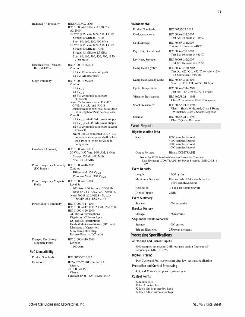
Radiated RF Immunity: IEEE C37.90.2-2004IEC 61000-4-3:2006 + A1:2007 +
A2:201020 V/m (>35 V/m, 80% AM, 1 kHz)
Sweep: 80 MHz to 1 GHz Spot: 80, 160, 450, 900 MHz
10 V/m (>15 V/m, 80% AM, 1 kHz)Sweep: 80 MHz to 1 GHz Sweep: 1.4 GHz to 2.7 GHz Spot: 80, 160, 380, 450, 900, 1850,
2150 MHz
Electrical Fast Transient Burst (EFTB):
IEC 61000-4-4:2012Zone A:
±2 kV: Communication ports±4 kV: All other ports
Surge Immunity: IEC 61000-4-5:2005Zone A:
±2 kVL-L±4 kVL-E±4 kV: communication ports
(Ethernet)Note: Cables connected to EIA-422,
G.703, EIA-232, and IRIG-B communications ports shall be less than 10 m in length for Zone A compliance.
Zone B:±1 kVL-L: 24–48 Vdc power supply±2 kVL-E: 24–48 Vdc power supply±2 kV: communication ports (except
Ethernet)Note: Cables connected to EIA-232
communications ports shall be less than 10 m in length for Zone B compliance.
Conducted Immunity: IEC 61000-4-6:201320 V/m; (>35 V/m, 80% AM, 1 kHz)
Sweep: 150 kHz–80 MHzSpot: 27, 68 MHz
Power Frequency Immunity (DC Inputs):
IEC 61000-4-16:2015Zone A:
Differential: 150 VRMSCommon Mode: 300 VRMS
Power Frequency Magnetic Field:
IEC 61000-4-8:2009Level 5:
100 A/m; 60 Seconds; 50/60 Hz1000 A/m 1 to 3 Seconds; 50/60 Hz
Note: 50G1P 0.05 (ESS = N, 1, 2) 50G1P 0.1 (ESS = 3, 4)
Power Supply Immunity: IEC 61000-4-11:2004IEC 61000-4-17:1999/A1:2001/A2:2008IEC 61000-4-29:2000
AC Dips & InterruptionsRipple on DC Power InputDC Dips & InterruptionsGradual Shutdown/Startup (DC only)Discharge of CapacitorsSlow Ramp Down/UpReverse Polarity (DC only)
Damped Oscillatory Magnetic Field:
IEC 61000-4-10:2016Level 5:
100 A/m
EMC Compatibility
Product Standards: IEC 60255-26:2013
Emissions: IEC 60255-26:2013, Section 7.1Class A
47 CFR Part 15BClass A
Canada ICES-001 (A) / NMB-001 (A)
Environmental
Product Standards: IEC 60255-27:2013
Cold, Operational: IEC 60068-2-1:2007Test Ad: 16 hours at –40°C
Cold, Storage: IEC 60068-2-1:2007Test Ad: 16 hours at –40°C
Dry Heat, Operational: IEC 60068-2-2:2007Test Bd: 16 hours at +85°C
Dry Heat, Storage: IEC 60068-2-2:2007Test Bd: 16 hours at +85°C
Damp Heat, Cyclic: IEC 60068-2-30:2005Test Db: +25 °C to +55°C, 6 cycles (12 +
12-hour cycle), 95% RH
Damp Heat, Steady State: IEC 60068-2-78:2013Severity: 93% RH, +40°C, 10 days
Cyclic Temperature: IEC 60068-2-14:2009Test Nb: –40°C to +80°C, 5 cycles
Vibration Resistance: IEC 60255-21-1:1988Class 2 Endurance, Class 2 Response
Shock Resistance: IEC 60255-21-2:1988Class 1 Shock Withstand, Class 1 Bump
Withstand, Class 2 Shock Response
Seismic: IEC 60255-21-3:1993Class 2 Quake Response
Event ReportsHigh-Resolution Data
Rate: 8000 samples/second4000 samples/second2000 samples/second1000 samples/second
Output Format: Binary COMTRADE
Note: Per IEEE Standard Common Format for Transient Data Exchange (COMTRADE) for Power Systems, IEEE C37.111-1999.
Event Reports
Length: 15/30 cycles
Maximum Duration: Five records of 24 seconds each at 1000 samples/second
Resolution: 1/4 and 1/8 samples/cycle
Digital Inputs: 2 kHz
Event Summary
Storage: 100 summaries
Breaker History
Storage: 128 histories
Sequential Events Recorder
Storage: 1000 entries
Trigger Elements: 250 relay elements
Processing SpecificationsAC Voltage and Current Inputs
8000 samples per second, 3 dB low-pass analog filter cut-offfrequency at 646 Hz, ± 5%
Digital Filtering
Two-Cycle and Full-cycle cosine after low-pass analog filtering
Protection and Control Processing
4, 8, and 32 times per power system cycle
Control Points
32 remote bits32 local control bits32 latch bits in protection logic32 latch bits in automation logic

SEL-487V Data Sheet Schweitzer Engineering Laboratories, Inc.
28
Relay Element Pickup Ranges and AccuraciesPhase-Voltage Differential Elements
Number of Elements: 3
Levels: 3 (Sensitive, Alarm, and Trip)
Pickup Range: Magnitude: 0.1 V to 300.00 V
Pickup Accuracy, Steady-State: ±0.1% of set point
Maximum Pickup/Dropout Time: 2.5 cycles
Timers: 3 levels with individual timers for each level (0.00 to 6000.00 seconds with 0.01 second resolution)
Time-Delay Range: 0.00–64000 cycles
Time-Delay Accuracy: ±0.1% ± 4.2 ms at 60 Hz
Reset Time Range: 0.00–64000 cycles
Torque Control: SELOGIC control equation
K Factor (Compensation) Range:
0.0000 to 1.9999 with 0.0001 resolution
Neutral-Voltage Differential Elements
Number of Elements: 3
Levels: 3 (Sensitive, Alarm, and Trip)
Pickup Range: Magnitude: 0.1 V to 300.00 VAngle: –179.00 to 180.00 degrees
Pickup Accuracy, Steady-State: ±0.1% of set point
Maximum Pickup/Dropout Time: 2.5 cycles
Timers: 3 levels with individual timers for each level (0.00 to 6000.00 seconds with 0.01 second resolution)
Time-Delay Range: 0.00–64000 cycles
Time-Delay Accuracy: ±0.1% ± 4.2 ms at 60 Hz
Reset Time Range: 0.00–64000 cycles
Torque Control: SELOGIC control equation
K Factor (Compensation) Range: 0.00 to 300.00 with 0.01 resolution
Phase-Current Unbalance Elements
Number of Elements: 3
Pickup Range: Magnitude: 0.005 to 20.00 per unit (INOM)
Pickup Accuracy, Steady-State: 0.05 per unit ± 1% of set point
Maximum Pickup/Dropout Time:
2.5 cycles for I > 0.05 per unit10 cycles for 0.002 < I < 0.05 per unit
Time-Delay Range: 0.00–16000 cycles
Reset Time Range: 0.00–16000 cycles
Time-Delay Accuracy: ±0.1% ± 4.2 ms at 60 Hz
Torque Control: SELOGIC control equation
Neutral-Current Unbalance Elements
Number of Elements: 3
Pickup Range: Magnitude: 0.005 to 20.00 per unit (INOM)
Pickup Accuracy, Steady-State: 0.05 per unit ± 1% of set point
Maximum Pickup/Dropout Time:
2.0 cycles for I > 0.05 per unit10 cycles for 0.002 < I < 0.05 per unit
Time-Delay Range: 0.00–400.0 s
Reset Time Range: 0.00–400.00 s
Time-Delay Accuracy: ±0.1% ± 4.2 ms at 60 Hz
Torque Control: SELOGIC control equation
Three Phase-Current Unbalance Elements
Number of Elements: 3 (W current channels only)
Pickup Range: 0.00 to 2.00 per unit (INOM)
Pickup Accuracy, Steady-State: ±1% of set point
Maximum Pickup/Dropout Time: 1.5 cycles
Time-Delay Range: 0.00–400.0 s
Time-Delay Accuracy: ±0.1% ± 4.2 ms at 60 Hz
Open-Phase Detection Logic
Number of Elements: 3 (W current channels only)
Pickup Range
1 A nominal: 0.05–1.00 A
5 A nominal: 0.25–5.00 A
Maximum Pickup/Dropout Time: 0.625 cycles
Instantaneous/Definite-Time Overcurrent Elements (50)
Phase- and Negative-Sequence, Ground-Residual Elements
Pickup Range
5 A nominal: 0.25–100.00 A secondary, 0.01 A steps
1 A nominal: 0.05–20.00 A secondary, 0.01 A steps
Accuracy (Steady-State)
5 A nominal: ±0.05 A plus ±3% of setting
1 A nominal: ±0.01 A plus ±3% of settings
Transient Overreach (phase and ground residual)
5 A nominal: ±5% of setting, ± 0.10 A
1 A nominal: ±5% of setting, ± 0.02 A
Transient Overreach (negative-sequence)
5 A nominal: ±6% of setting, ± 0.10 A
1 A nominal: ±6% of setting, ± 0.02 A
Time-Delay Range: 0.00–16000.00 cycles, 0.250 cycle steps
Timer Accuracy: ±0.250 cycle ± 0.1% of setting
Maximum Pickup/Dropout Time: 1.5 cycles
Adaptive-Time Overcurrent Elements (51)
Pickup Range (Adaptive within the range)
5 A nominal: 0.25–16.00 A secondary, 0.01 A steps
1 A nominal: 0.05–3.20 A secondary, 0.01 A steps
Accuracy (Steady-State)
5 A nominal: ±0.05 A ± 3% of setting
1 A nominal: ±0.01 A ± 3% of settings
Transient Overreach
5 A nominal: ±5% of setting, ± 0.10 A
1 A nominal: ±5% of setting, ± 0.20 A
Time Dial Range (Adaptive within the range)
U.S.: 0.50–15.00, 0.01 steps
IEC: 0.05–1.00, 0.01 steps
Curve Timing Accuracy: ±1.50 cycles plus ±4% of curve time (for current between 2 and 30 multiples of pickup). Curves operate on definite-time for current greater than 30 multiples of pickup.
Reset: 1 power cycles or Electromechanical Reset Emulation time
Phase Under- and Overvoltage Elements
Based on maximum of the VA, VB, and VC phase voltages
Pickup Range: 0.25 V–300 VLN in 0.01 steps

Schweitzer Engineering Laboratories, Inc. SEL-487V Data Sheet
29
Accuracy: ±3% of setting, ± 0.5 V
Transient Overreach: ±5% of pickup
Maximum Delay: 1.5 cycles
Phase-to-Phase Under- and Overvoltage Elements
Elements based on maximum of the calculated phase-to-phase voltages
Pickup Range: 0.25–520 VLL in 0.01 steps
Accuracy: ±3% of setting, ± 0.5 V
Transient Overreach: ±5% of pickup
Maximum Delay: 1.5 cycles
Sequence Under- and Overvoltage
Pickup Range: 0.25 V–300 VLN in 0.01 steps
Pickup Accuracy, Steady State: ±5% of setting, ± 1 V
Pickup Accuracy, Transient Overreach: ±5%
Maximum Pickup/Dropout Time: 1.5 cycles
Under- and Overfrequency Elements
Pickup Range: 40.01–69.99 Hz, 0.01 Hz steps
Accuracy, Steady State plus Transient:
±0.005 Hz for frequencies between 40.00 and 70.00 Hz
Maximum Pickup/Dropout Time: 3.0 cycles
Time-Delay Range: 0.04–400.0 s, 0.01 s increments
Time-Delay Accuracy: ±0.1% ± 0.0042 s
Pickup Range, Undervoltage Blocking: 20.00–200.00 VLN (Wye)
Pickup Accuracy, Undervoltage Blocking: ±2% ± 2 V
Maximum Pickup/Dropout Time: 2.625 cycles
Breaker Failure Instantaneous Overcurrent
Setting Range
5 A nominal: 0.50–50 A, 0.01 A steps
1 A nominal: 0.10–10.0 A, 0.01 A steps
Accuracy
5 A nominal: ±0.05 A ± 3% of setting
1 A nominal: ±0.01 A ± 3% of settings
Transient Overreach
5 A nominal: ±5%, ± 0.10 A
1 A nominal: ±5%, ± 0.02 A
Maximum Pickup Time: 1.5 cycles
Maximum Dropout Time:Less than 1 cycle
Maximum Reset Time: Less than 1 cycle
Timer Setting Range: 0–6000 cycles, 0.125 cycle steps
Time-Delay Accuracy: ±0.1% of setting ± 0.125 cycle
Directional Over- and Underpower Element
Pickup Range: 3-phase: OFF, 1–900 W (secondary) in 1 W steps
Single phase: OFF, 0.30–900 W (secondary) in 0.1 W steps
Pickup Accuracy: ±3% of setting and ±5 W, power factor > ±0.5 at nominal frequency
Time-Delay Range: 0–16,000 cycles, 0.125 cycle increment
Time-Delay Accuracy: ±0.1% of setting, ± 0.125 cycle
Bay Control
Breakers: 1
Disconnects (Isolators): 10 (maximum)
Timers Setting Range: 1–99999 cycles, 1-cycle steps
Time-Delay Accuracy: ±0.1% of setting, ± 0.125 cycle
Station DC Battery System MonitorRated Voltage: 24–250 Vdc
Operational Voltage Range: 0–350 Vdc
Input Sampling Range: 2 kHz
Processing Rate: 1/8 cycle
Operating Time: 1.5 seconds (element dc ripple)1.5 cycles (all elements but dc ripple)
Setting Range
DC Settings: 1 Vdc steps (OFF, 15–300 Vdc)
AC Ripple Setting: 1 Vac steps (1–300 Vac)
Pickup Accuracy: ±10%, ± 2 Vdc (dc ripple)±3%, ± 2 Vdc (all elements but dc ripple)
Metering AccuraciesAll metering accuracies are based on an ambient temperature of 20°C
and nominal frequency.
Absolute Phase-Angle Accuracy:
IA, IB, and IC per terminal: ±0.5° (both 1 and 5 A)
VA, VB, and VC per terminal:±0.125°
Currents
Quantity: IA, IB, IC Per Terminal
INOM = 1 A
Magnitude Accuracy: ±0.2%, ± 0.8 mA
Phase Accuracy: ±0.2°
Current Range: 0.5–3.0
INOM = 5 A
Magnitude Accuracy: ±0.2%, ± 4.0 mA
Phase Accuracy: ±0.2°
Current Range: 2.5–15.0
Quantity: 3I0 (IG), I1 and 3I2 (Calculated) Per Terminal
INOM = 1 A
Magnitude Accuracy: ±0.3%, ± 0.8 mA
Phase Accuracy: ±0.3°
Current Range: 0.1–20.0
INOM = 5 A
Magnitude Accuracy: ±0.3%, ± 4.0 mA
Phase Accuracy: ±0.3°
Current Range: 0.5–100.0
Quantity: VA, VB, VC Per Terminal
Voltage Range: 5–33.5 V
Magnitude Accuracy: ±2.5% ± 1 V
Phase Accuracy: ±1.0°
Voltage Range: 33.5–300 V
Magnitude Accuracy: ±0.1%
Phase Accuracy: ±0.5°
Quantity: 3V0, V1, V2 Per Terminal
Voltage Range: 5–33.5 V
Magnitude Accuracy: ±2.5% ± 1 V
Phase Accuracy: ±1.0°

SEL-487V Data Sheet Schweitzer Engineering Laboratories, Inc.
30
Voltage Range: 33.5–300 V
Magnitude Accuracy: ±0.1%
Phase Accuracy: ±0.5°
Quantity: VAB, VBC, VCA (Calculated, Per Terminal)
Voltage Range: 5–33.5 V
Magnitude Accuracy: ±2.5% ± 1 V
Phase Accuracy: ±1.0°
Voltage Range: 33.5–300 V
Magnitude Accuracy: ±0.1%
Phase Accuracy: ±0.5°
Quantity: MW (P), Per Phase (Wye), Three Phase (Wye) Per Ter-minal
Accuracy: ±1%
Range: (0.1–1.2) • INOM, 33.5–300 Vac, PF = 1, 0.5 (single phase)
Accuracy: ±0.7%
Range: (0.1–1.2) • INOM, 33.5–300 Vac, PF = 1, 0.5 (three phase)
Quantity: MVAR (Q), Per Phase (Wye), Three Phase (Wye) Per Terminal
Accuracy: ±1%
Range: (0.1–1.2) • INOM, 33.5–300 Vac, PF = 1, 0.5 (single phase)
Accuracy: ±0.7%
Range: (0.1–1.2) • INOM, 33.5–300 Vac, PF = 1, 0.5 (three phase)
Quantity: MVA (S), Per Phase (Wye), Three Phase (Wye) Per Terminal
Accuracy: ±1%
Range: (0.1–1.2) • INOM, 33.5–300 Vac, PF = 1, 0.5 (single phase)
Accuracy: ±0.7%
Range: (0.1–1.2) • INOM, 33.5–300 Vac, PF = 1, 0.5 (three phase)
Quantity: PF, Per Phase (Wye), 3- (Wye) Per Terminal
Accuracy: ±1%
Range: (0.1–1.2) • INOM, 33.5–300 Vac, PF = 1, 0.5 (single phase)
Accuracy: ±0.7%
Range: (0.1–1.2) • INOM, 33.5–300 Vac, PF = 1, 0.5 (three phase)
Frequency Accuracy
Accuracy: 0.01 Hz
Range: 40–65 Hz
Magnitude Accuracy
Accuracy: ±1%
Range: 40–65 Hz
Power Supply Voltage Range
100–275 Vdc
Accuracy: ±1%
RMS Metering
Voltage Metering Function:
VAY, VBY, VCY, VAZ, VBZ, VCZ (4-wire wye connected)
Range: 2–300 V (PT)
Magnitude Accuracy (at 20°C and Nominal Frequency): ±1.2%
Current Metering Function: IAW, IBW, ICW
Range: 0.05–20.0 •INOM (INOM = 1 A, 5 A)
Magnitude Accuracy (at 20°C and Nominal Frequency): ±0.2% ± 0.5 mA
Unbalance Metering
Quantity: Differential Voltage dVA, dVB, dVC, dVG1, dVG2, dVG3
Accuracy: ±1.0%
Range: ±0.01 V to ±100.00 V
Quantity: Unbalance Current 60N/60P
Magnitude Accuracy: ±0.3%
Phase Accuracy: ±0.3°
Current Range: at 0.001 to 5.000 • INOM
K Compensation Factors
Magnitude Accuracy: ±1.0% ± 0.002 • KSET
Phase Angle Accuracy: ±0.3°
Optional RTD Elements (RTD Temperature Measurement From SEL-2600 Series RTD Module)
12 RTD inputs via SEL-2600 Series RTD Module and SEL-2800
Fiber-Optic Transceiver
Monitor Ambient or Other Temperatures
PT 100, NI 100, NI 120, and CU 10 RTD-Types Supported, FieldSelectable
Up to 500 m Fiber-Optic Cable to SEL-2600 Series RTD Module
Synchrophasors
Number of Synchrophasor Data Streams: 5
Number of Synchrophasors for Each Stream:
12 phase synchrophasors (6 voltage and 6 currents)
4 positive-sequence synchrophasors (2 voltage and 2 currents)
Number of User Analogs for Each Stream: 16 (any analog quantity)
Number of User Digitals for Each Stream: 64 (any Relay Word bit)
Synchrophasor Protocol: IEEE C37.118-2005,SEL Fast Message (Legacy)
Synchrophasor Data Rate: As many as 60 messages per second
Synchrophasor Accuracy:
Voltage Accuracy: ±1% Total Vector Error (TVE)Range 30–150 V, fNOM ±5 Hz
Current Accuracy: ±1% Total Vector Error (TVE)Range (0.1–20) • INOM A, fNOM ±5 Hz
Synchrophasor Data Recording:
Records as much as 120 sIEEE C37.232 File Naming Convention
Breaker Monitoring
Running Total of Interrupted Current (kA) per Pole: ±5% ± 0.02 • INOM
Percent kA Interrupted for Trip Operations: ±5%
Percent Breaker Wear per Pole: ±5%
Compressor/Motor Start and Run Time: ±1 day
Time Since Last Operation: ±1 day

Schweitzer Engineering Laboratories, Inc. SEL-487V Data Sheet
31
Battery System Monitoring
Pickup Range: 15–300 Vdc, 1 Vdc steps
Pickup Accuracy: ±3% of setting, ± 2 Vdc (all elements except dc ripple)
±10% of setting, ± 2 Vdc (dc ripple element)
Maximum Pickup/Dropout Time:
±1.5 cycles (all elements except dc ripple)±1.5 seconds (dc ripple element)
Sampling Rate: 1/8 cycle
Voltage Sag/Swell/Interruption Reporting
Pickup Range
Sag: 10.00%–95.00%
Swell: 105.00%–180.00%
Interruption: 5.00%–95.00%
Recording Rates and Duration
Fast: 4 samples/cycle 4 cycle dur.
Medium: 1 sample/cycle 176 cycle dur.
Slow: 1 sample/64 cycles 4096 cycle dur.
Daily: 1 sample/day Indefinite
Control Functions (SEL-487V-1)Voltage Control
Dead-Band Range: 10.00–300.00 V sec.
Dead-Band Control Delay: 1–6000 s
Stall-Time Delay: 1–6000 s
Power Factor Control
Dead-Band Range: 0.01–0.99
Dead-Band Control Delay: 1–6000 s
Stall-Time Delay: 1–6000 s
Minimum Operating Power: ±1 W or ±1 VAR sec.
VAR Control
Dead-Band Range: –1000.00 to +1000.00 VAR sec.
Dead-Band Control Delay: 1–6000 s
Stall-Time Delay: 1–6000 s
Minimum Operating Power: ±1 W or ±1 VAR sec.
Time-of-Day Control
Minimum Resolution: ±1 minute
Universal Sequencer
Accumulation Period: 1–9999 minutes
Resolution: ±1 minute
Accumulated Value: 0–2147483646
Resolution: ±1

32
© 2009–2021 by Schweitzer Engineering Laboratories, Inc. All rights reserved.
All brand or product names appearing in this document are the trademark or registeredtrademark of their respective holders. No SEL trademarks may be used without writtenpermission. SEL products appearing in this document may be covered by U.S. and Foreignpatents.
Schweitzer Engineering Laboratories, Inc. reserves all rights and benefits afforded underfederal and international copyright and patent laws in its products, including without lim-itation software, firmware, and documentation.
The information in this document is provided for informational use only and is subject tochange without notice. Schweitzer Engineering Laboratories, Inc. has approved only theEnglish language document.
This product is covered by the standard SEL 10-year warranty. For warranty details, visitselinc.com or contact your customer service representative.
*PDS487V-01*
2350 NE Hopkins Court • Pullman, WA 99163-5603 U.S.A.
Tel: +1.509.332.1890 • Fax: +1.509.332.7990
selinc.com • [email protected]
SEL-487V Data Sheet Date Code 20210708
Top Related