Zustands-Mengenumwerter EC 24 Volume Corrector EC 24 und ... · with electronic turbine meters from...
46
Operating Instructions EC 21 Volume Correction via Temperature EC 24 Volume Correction via Pressure and Temperature Software version 1.0 Status: May 2005 RMG Messtechnik GmbH Otto-Hahn-Str. 5 · 35510 Butzbach (Germany) P.O.B. 280 · 35502 Butzbach (Germany) Tel.: +49 (0)6033 897-0 · Fax: +49 (0)6033 897-130 Serving the Gas Industry – WORLDWIDE Volume Corrector EC 24 and Temperature Corrector EC 21
Transcript of Zustands-Mengenumwerter EC 24 Volume Corrector EC 24 und ... · with electronic turbine meters from...

Operating Instructions
EC 21 Volume Correction via Temperature
EC 24 Volume Correction via Pressure and Temperature
Software version 10
Status May 2005
RMG Messtechnik GmbH Otto-Hahn-Str 5 middot 35510 Butzbach (Germany) POB 280 middot 35502 Butzbach (Germany) Tel +49 (0)6033 897-0 middot Fax +49 (0)6033 897-130
Serving the Gas Industry ndashWORLDWIDE
Zustands-Mengenumwerter EC 24 und
Temperatur-Mengenumwerter EC 21
Volume Corrector EC 24 and
Temperature Corrector EC 21
Table of Contents
Introduction 1 General information 1 The system 2
Operating Modes 4 Safety Instructions 5 Installation 6
Electrical connections 6 Installing the remote totalizer 10
Operation 11 Front panel and keyboard 11 Display 12 Programming 13 Parameters and modes of the EC 21 EC 24 16 Coordinate system 18 Description of individual columns 19 Error messages 24 Changing the battery 25
Annexes 26 A Equations 26 B Block diagram of the EC 21 EC 24 28 C Specifications 29 D Examples of connection 36 E Instructions for the measuring element of the turbine meter 38 F Dimensions 42 G Operating instructions for the installer 43 H EC type approval certificate 45
Introduction
Operating Instructions for the EC 21 EC 24 1
Introduction General information Design variants The EC 21 temperature corrector (correction is made via the temperature measured and a fixed pressure value) or the EC 24 volume corrector (correction is performed using measured pressure and temperature values) can be used as a unit together with electronic turbine meters from RMG or separately with any mechanical turbine or rotary displacement meters The following device types are available Device type TERZ 94 TRZ 03 TE
TRZ 03 TEL EC 21 EC 24 EC 24
(pulse input) Measuring element (meter)
electronic electronic electronic electronic mechanical
Function Vm totalizer Vm totalizer Vm totalizer and volume correction (T)
Vm totalizer and volume correction (pT)
Vm totalizer and volume correction (pT)
Case
Inputs Wiegand (1 or
2 channels) Wiegand (1 or 2 channels)
Wiegand (1 or 2 channels)
Wiegand (1 or 2 channels)
Reed (1 chan-nel)
Pulse compa-rison
No Yes Optional Optional No
Pulse outputs LF HF LF HF LF HF LF HF LF There are various hardware configurations for the device types listed - without current output Mother board - with current output (4 to 20 mA) S board
and additional boards for - pulse comparison (not available for the TERZ 94) - RS 485 interface (for Modbus) - memory submodule with clock If the corrector is used together with an electronic RMG turbine meter please observe the instructions for the measuring element in the annex to this manual
Introduction
2 Operating Instructions for the EC 21 EC 24
The operating concept The operating concept has been chosen in such a way that the operator can easily use the device without wasting too much time reading a manual
The coordinate system A coordinate system makes it easy for the operator to access all configuration data as well as measured and calculated values by means of a table The coordinate system is based on 8 columns Every value in this coordinate system can be reached by pressing the appropriate cursor keys (arrows ldquoldquo ldquoldquo)
The display field An alphanumeric single-line display with 12 characters enables data and measured values to be indicated together with their abbreviated designations and units The LCD has been designed in such a manner that it is particularly suitable for battery-powered mode At temperatures below -20degC or exceeding +60degC the display may be impaired The system A complete Flow Computer System has been developed on the surface of a few square centimetres using the most advanced SMD technology with large-scale integrated components Several device functions such as pulse counting frequency measurement keyboard controller and dispatcher output have been incorporated into a controller Thanks to large-scale integrated components fewer chips are required and this also contributes to making the device reliable The type of the individual device essentially depends on the software used
Introduction
Operating Instructions for the EC 21 EC 24 3
Program memory The program memory of the base device is located in a flash memory on the main board whereas the data memory is located on an additional board
Reset In the case of a reset the power supply is disrupted and the corrector is switched off during this period of time In this way the program and the operating parameters will not be lost and also the meter readings will be retained A reset is made on the EC 21 24 by switching off not only the battery but also a possibly available external power supply
Operating Modes
4 Operating Instructions for the EC 21 EC 24
Operating Modes Battery-powered device The EC 21 is fitted with an exchangeable battery and the EC 24 is fitted with two exchangeable batteries Both devices have been designed for a continuous operation over six years This however is conditional on the device being either read or ldquowoken uprdquo by pressing the external button once a week Battery-powered device with an external power supply If an interface submodule is used for transmitting data such as the externally supplied RS 485 the service life of the battery is more than 10 years Externally supplied device with built-in standard battery In the case of an external power supply (current transmitter which serves as a power supply and 4 to 20 mA current output at the same time) the EC 21 EC 24 is completely supplied via a current loop For this purpose a power supply unit is required which is to be connected to this output In the case of the EC 24 volume corrector pulse processing is even ensured in the event of a power failure of the current loop If pulse processing is to be maintained with the EC 21 even in the case of a power failure of the current loop a standby battery (available as an option) can be installed which will bridge the power supply during a period of up to six months Display of battery change Lithium batteries retain their voltage until they are almost completely discharged so that the voltage cannot be monitored with an appropriate display until the next battery change is necessary
Safety Instructions
Operating Instructions for the EC 21 EC 24 5
Safety Instructions The EC 21 and the EC 24 comply with currently applicable standards and regulations However failure to operate them properly may cause hazards Persons who install or operate a volume corrector in areas subject to explosion hazards must be familiar with the currently applicable explosion protection standards and regulations Do not change anything of the volume corrector on your own otherwise the approval will become invalid Operate the volume corrector only in the specified temperature range from -20degC to +60degC The electronic corrector system of the explosion-protected design has been approved for use in areas subject to explosion hazards and its code is
II 2 G EEx ib[ia] IIC T4 or T3 You can find the EC type approval certificate in the annex and its reference number is TUumlV 02 ATEX 1970 Please observe the following signs
Danger of explosion In the manual this symbol warns you of an explosion hazard Please observe the instructions given next to this symbol As to the danger of explosion please note the following in particular
bull Only the explosion-protected design of the EC 21 EC 24 may be used in areas subject to explosion hazards
Damage to property In the manual this symbol warns you of possible damage to property The instructions given next to this symbol inform you about what you can do to avoid damage to the EC 21 EC 24 volume corrector
It is essential to observe the warning information in these operating instructions and the generally applicable safety rules No warranty claims can be asserted if there is unauthorized interference with the device
Installation
6 Operating Instructions for the EC 21 EC 24
Installation Electrical connections To reach the electrical connections you must first remove the cover of the corrector
You must select the sensor inputs before you connect the cables To do this install the jumpers XS1 XS2 and XTERZ90 on the board as indicated (see inputs and outputs in the annex)
Make your settings of X_S1 and X_S2 as follows Reed contact Wiegand TERZ90
Remote totalizer EZSENS01 IG04
X5 effective X5 effective X5 effective X6_0 effective Jumpers 1-3 amp 2-4 Jumpers 3-5 amp 4-6 Jumpers 1-2 amp 3-4 All open
Controlling the start-stop totalizer or resetting the resettable totalizer (depending on the programming of the electronic totalizing unit) is performed through input X5 terminals 1 and 2 As soon as input X5 terminals 1 2 has been short-circuited through an external contact interruption or resetting is performed rArr For this purpose set jumpers at the positions identified with X_S2 to the ldquoreed contactrdquo function
Plug X2_0 for TERZ94trm current module and supply
Terminal block X4 Pulse outputs
Terminal block X15 Data interface
Sockets X151 and X152 to accommodate an interface
Plug X3 service module
Pin connector for button on the case
Plug X16_0 TERZ94p pressure sensor
Reset (soldering pads)
Terminals X5 Pulse inputs
Plug X6_0 EZSENS01
Terminals X9 PT-1000 sensor
Plug X10-0 Semiconductor temperature sensor
Configuration of pulse inputs X_S1 and X_S2 for terminals or the EZSENS01 board
Installation
Operating Instructions for the EC 21 EC 24 7
In the case of the EC 21 EC 24 terminal X22 (on TERZ94trm current module) is used as current-loop connection to supply the device and as output current (4-20 mA) The output signals can be picked up at the following terminals HF signals Output X4 terminals X44 (+) X43(-) LF signals Output X4 terminals X42 (+) X41(-) Now connect the cables and then put the cover again on the lower part of the housing To connect the cables to the spring terminals you need a screwdriver with a blade width of a maximum of 25 mm Introduce the blade into the intended slot and press down the screwdriver to open the spring terminal Standard connection pulse outputs 7-pin connector (Binder)
1 - 4 + LF signal (Vm or Vb) 2 - 5 + Fault (for all battery devices and for Ex devices with external supply) or Current output 4 to 20 mA (for non-Ex devices with external supply only) 3 - 6 + HF signal (view on device)
Standard connection interface 7-pin connector (Lumberg) 1 - 4 + RS485 supply 3 - 5 + RS485 data line 2 Spare 6 7 Calibration switch (view on device)
In areas subject to explosion hazards the EC 21 EC 24 must only be connected to certified intrinsically safe circuits Make sure that the limit values specified in the certificate of conformity (see annex) for the devices to be connected are not exceeded
If one or more than one circuit is used make sure that the permissible limit values in accordance with the EC type approval certificate are not exceeded Each intrinsically safe signal circuit must be installed in a separate cable which is to be taken through an appropriate high-strength cable gland It is absolutely imparative that the intrinsically safe cables are permanently installed Make sure that the connecting cables are provided with core-end sleeves
6
5
43
2
PE (screening)
1
7
3
542
1
6
Installation
8 Operating Instructions for the EC 21 EC 24
Earthing
To prevent measuring errors caused by electromagnetic interference you must not fail to earth the case of the meter head via the earthing screw on the left side of the case
Cables
Use 2-core or multicore shielded cables which are twisted together in pairs (type LIYCY) for the signal lines (LF output HF output current-loop connection control input) Use 4-core shielded cables which are twisted together in pairs (type LIYCY) for the data lines (RS 485) The shielding must always be connected to earth on both sides In the case of the EC 21 EC 24 you must proceed as described under ldquoCable glandsrdquo We recommend that cable cross sections of 05 mm2 are used Due to the cable gland the outside diameter must be between 45 mm and 65 mm If the device is used in areas subject to explosion hazards the maximum cable length is limited by the limit values for intrinsically safe circuits and depends on the inductance and capacitance of the cable
Minimum cable cross section Up to a length of 10 m 6 mm2 From a length of 10 m 10 mm2
Earthing screw
Installation
Operating Instructions for the EC 21 EC 24 9
Cable glands
Clamp the shielding on both sides as shown in the picture below into the cable glands located on the outside of the case
bull Unscrew the cap nut bull Pull out the plastic clamping piece bull Push the cable end through the cap nut and the clamping piece and bend the
shielding backwards bull Put the clamping piece back into the connecting piece bull Screw on the cap nut again
Permissible temperature ranges
For the standard design the following fluid temperature and ambient temperature ranges are permitted Fluid temperature range -20degC to +60degC Ambient temperature range -20degC to +60degC or 40degC
Cap nut
Clamping piece
O-ring
Connecting piece
Installation
10 Operating Instructions for the EC 21 EC 24
Installing the remote totalizer
ServicemodulTERZ94trm
TERZ94p
Impulsausgaumlnge
Datenschnittstelle
Datenschnittstelle
EZDRS-485 Boot
TP-GND
Impulseingang
X2_0
X4
X15
X9X
151
X5
CX
2
CX
3
CX6
CX
1
L1
X6_0
X152
X_S1
XLP1
Ree
d 1+
3 2
+4S
enso
rver
staumlr
ker 3
+4W
iega
nd 3
+5
4+6
4
2 6
531X_S2 X10-0
TEMP_LM7X
EZSENS01
PT1000
5313
2
1
C21
C1
V12
V13
V14
C22
Q1
X7
X16_0X1X3 Taster
RESET
X_TERZ90
S3 S1 S2 S4P
+
+-
-
4
5
61
2
3
Sensor
Sensor
ZaumlhlwerkZaumlhlwerk
-
-
+
+Index InputIndex Input
-
+
Sensor
Sensor
ZaumlhlwerkZaumlhlwerk
-
-
+
+Index InputIndex Input
-
+
Herst-NrHerst-Jahr
MESSTECHNIK GMBH35510 Butzbach
Vm3
Vm h3
Pbara
TdegC Zu
IomA
ErrorTyp Mode
Trockenes Gas im Normzust101325 bar0degC = 0Weitere Daten ldquoTyp-Schildrdquo
ϕ - 0102
Non Ex
If your model is designed for remote totalizing you can install the totalizer at a distance of up to 3 m from the meter case Usually the cable has already been connected to the sensor and the totalizing unit when the device is delivered Should this not be the case you will have to connect the connecting cable to input X5 terminals S1+ and S1- of the board If you have a 2-channel meter connect the second sensor to the clamps S2+ and S2- Use only shielded cables of the type LIYCY - 2 x 075 blue (1-channel Ex) LIYCY - 2 x 2 x 075 blue (2-channel Ex or 1-channel Non-Ex) LIYCY - 3 x 2 x 075 blue (2-channel Non-Ex) Maximum cable length 3 m
In hazardous areas the temperature transmitter must not be connected via the socket on the meter case In this case it is prescribed to lay a separate cable for the temperature transmitter
In addition check the plug-in jumpers XS1 XS2 and XTERZ90 on the board (see inputs and outputs in the annex) Make your settings of XS1 and XS2 as follows jumpers 3-4
Operation
Operating Instructions for the EC 21 EC 24 11
Operation Front panel and keyboard of the EC 24
ZuVm3 OutI
mAoT
degCP
baraV
m h3ErrorTyp
VOLUME CORRECTOREC 24
IP65
Further datapress buttons
II2G EEx ib ia IIC T3T4TUumlV 02 ATEX1970
-20degC +60degC40degC Ta EG-type examination certificate
Current output 4-20mA yes no
Ser-NoYear
MESSTECHNIK GMBHGermany
0085 0032
00123456Nm3
Keyboard Designation Effect
Arrow Down
bull Moves downwards within a list Moves from the first value of the list towards the last value
Arrow Right bull Moves to the right towards another list
Moves from the first list towards the last list
+ Function
Press both buttons at the same time to initiate the following functions Hold down gt2 sec Segment test Hold down lt 2 sec The coordinate will be displayed
If the EC 21 EC 24 is operated together with the measuring element of an electronic turbine meter the EC 21 EC 24 contains the totalizing unit of the meter and the data plate of the meter is located on the left side of the front panel
Operation
12 Operating Instructions for the EC 21 EC 24
Display In normal operating mode the main totalizer is displayed If you press the external control buttons you can select the other display values After an adjustable time has elapsed the EC 21 EC 24 will return to displaying the main totalizer If the display of the EC 21 EC 24 does not show anything the device is in energy-saving mode In this mode the display is completely switched off However incoming pulses are processed and the outputs are set If you press one of the two control buttons the display value will appear again Display switched off
Pointer position 1 0 0 0 0 5 8 3 1 m3
Main totalizer V
Pointer position 2 1 0 0 0 0 m3h Flow rate V
Pointer position 3 1 0 0 0 0 0 0 0 bara
Pressure P
Pointer position 4 20 0 0 0 0 0 0 degC
Temperature T
Pointer position 5 1 --
Conversion factor C (Analysis)
Pointer position 6 16 0 0 0 0 0 0 mA
Current Io
Pointer position 7 1 --
Error ID
Pointer position 8 1 --
Mode Memory
Operation
Operating Instructions for the EC 21 EC 24 13
Programming Via the parameterization and readout software The parameters of the EC 21 EC 24 can be changed using the parameterization and readout software The official parameters are protected by a calibration switch and a password The link between the laptop computer and the corrector is established via the RS 485 interface of the EC 21 24 Via the programming module For programming the EC 21 EC 24 there are four buttons on the bottom of the display board Alternatively you can program the device using the programming module (available as an accessory) The programming module is to be connected via a pin connector (see the picture below)
P crarr
orand
Programming with the programming module is to be performed in the same way as with the internal buttons
P + -
|rarr
Operation
14 Operating Instructions for the EC 21 EC 24
The external and internal buttons correspond to each other in the following way Int button Ext button Meaning
P P Display mode Switch over to programming mode (Press the button longer than 2 seconds) Programming mode Put the decimal point at the current position
+ and In display mode Move to the right within the matrix (change of column) In programming mode - Increase the decimal by 1 - Scroll in the list (Display value is identified by ldquoLldquo)
- or
In display mode Move towards the bottom (change of line) In programming mode - Decrease the decimal by 1 - Scroll in the list (Display value is identified by ldquoLldquo)
|rarr |rarr In display mode Short-term view of the coordinate (eg A01) In programming mode Go to the right by one decimal place (if the last decimal has been reached Quit programming mode)
Operation
Operating Instructions for the EC 21 EC 24 15
Principle of programming For programming you must always proceed as follows bull First change over to the display value to be modified
minus To do this press either the control button (only forwards) minus or the internal buttons ldquo+rdquo and ldquo-rdquo or the external buttons ldquoandrdquo and ldquoorrdquo (forwards
and backwards) bull Change to programming mode by pressing ldquoPrdquo for at least 2 seconds On the left
side of the display a flashing character or cursor will appear
0 1 2 32 3 Pm3bull You can now modify the flashing decimal by pressing either ldquo+rdquo or ldquoandrdquo (+1) or ldquo-rdquo or
ldquoorrdquo (-1) Example If you press the ldquoandldquo button three times the first decimal will be increased from 0 to 3 If an ldquoLrdquo appears on the far left side of the display this value is a list With a list you can only scroll in the specified values
bull After you have completed your programming of the first decimal press ldquo|rarr rdquo once and the next character will start to flash Now proceed with your programming until you have reached the last decimal place
bull Then press ldquo|rarrrdquo once again to have the set value accepted and quit programming mode
bull Press the ldquoPldquo button to set the decimal point behind the flashing digit With totalizers modes and integers no decimal point is permitted
bull Press the control button if you have made an error or if you want to discontinue inputting data
Display values Measured values such as the flow rate frequency etc are display values and cannot be directly modified However there are many parameters which influence the formation of these measured values These parameters are described in the following section Display values include the flow rate version number year of construction serial number value of the current output in mA for example
Flashing character
Operation
16 Operating Instructions for the EC 21 EC 24
Parameters and modes of the EC 21 EC 24 The following sections describe the meaning of the individual parameters Meter factor (pulse value) With the meter factor (pulse value) the relevant flow rate at measurement conditions is calculated from the signal frequency of the sensor element in the electronic totalizing unit
sdot=
hm3600
KfQ
3
M
f Signal frequency (Hz) K Meter factor (pulsesm3) QM Flow rate at measurement conditions (m3h) The meter factor has been calibrated in the factory in such a way that working cubic metres are directly displayed Any modification of this adjustment is within the sphere of responsibility of the operating company NOTE The new value is immediately used for all calculations performed after each modification of the meter factor The uninfluenced signal frequency of the sensor element is available at the HF output The frequency range can be determined from the meter factor K and the minimum and maximum flow rates at measurement conditions of the meter in accordance with the following formulae
K3600Qf minM
min sdot= K3600Qf maxM
max sdot=
QMmin Minimum flow rate at measurement conditions QMmax Maximum flow rate at measurement conditions K Meter factor (pulse value) Example QMmin = 16 m3h QMmax = 250 m3h K = 2362 pulsesm3
Hz510Hz2362360016fmin =sdot= Hz164Hz2326
3600250fmax =sdot=
Operation
Operating Instructions for the EC 21 EC 24 17
Totalizer factor (decimal places)
You can set the totalizer factor in coordinate Z 01 There are the following setting options
Totalizer factor Multiplier for value displayed
Decimal places
001 2 01 1 1 0 10 10 0 100 100 0
Example If the factor has been set to 01 the meter reading will be displayed with one decimal If the factor has been set to 10 the value displayed will be shown without decimals and you will obtain the actual meter reading by multiplying the value displayed by 10 Output pulse value
The output pulse value indicates how many LF output pulses correspond to one cubic metre The output pulse value can be entered in coordinate Z 02 from 001 to 100 as required
Operation
18 Operating Instructions for the EC 21 EC 24
Coordinate system
Pointer position V V P T
Designation Totalizers Flow Rate Pressure Temperature Coordinate
Line A B C D
1 Volume at base conditions Qb bara degC
2 Volume at measurement conditions Qm p min t min
3 Disturbing quantity totalizer Vb
Frequency p max t max
4 Disturbing quantity totalizer Vm Qm min pb specified value tb specified value
5 Pulse scaling factor Qm max p default t default
6 Meter factor Qm max val p binary display Factor adjustment value
7 Binary value at 05 V Offset adjustment value
8 Binary value at45 V AD binary value 9 U min
10 Monthly data memory pu min 11 Monthly data memory Rise 12 Monthly data memory Factor correction value 13 Monthly data memory Offset correction value
14 23 Monthly data memory
Pointer position
C Io Error Type Mode
Designation Analysis Outputs Error ID Mode Memory Coordinate
Line E F G Z
1 Conversion factor Current Error text TerzMode 2 K coefficient Current min Software version EcMode 3 K specified value Current max Serial number Puls_X 4 Hs Current default Checksum Puls_Y
5 Rhon Current rise Ser no pressure transmitter Time
6 CO2 Current offset p min Date 7 Zb Current damping p max Modbus address
8 Z Ser no temperature transmitter ModbusRegOffset
9 Hs ref temp T min Error bit string 10 T max Wake-up pulse 11 Ser no meter 12 Meter size 13 Battery change
Operation
Operating Instructions for the EC 21 EC 24 19
Description of individual columns Column structure
Pointer position V
Coding Coordinate Line A Description of the coordinate Unit Special feature
S 1 Nm3 Main totalizer volume at base conditions m3
S 2 m3 Main totalizer volume at measurement conditions m3
S 3 VbD Disturbing quantity totalizer volume at base conditions m3
S 4 VmD Disturbing quantity totalizer volume at measurement conditions m3
The calibration switch is realized by a jumper in the (female) interface connector For opening the calibration switch just remove the jumper Then all parameters coded with ldquoSrdquo or ldquoCrdquo can be changed
Designation of columns A to O
Press the above function key and then the key once
Unit of the value displayed or programmed
Abbreviated designation of the matrix field
Field designation shown in the display of the EC 21 EC 24
Explanatory notes on a coordinate field
Designation of the column line
Coding of the matrix fields H = Header D = Display value C = Access to a data field which is protected by the user code S = Access to a data field which is protected by the calibration switch
7
3
542
1
6
Note In the software version 10 the user code is not yet implemented To change parameters with ldquoCrdquo coding it is necessary to open the calibration switch
Operation
20 Operating Instructions for the EC 21 EC 24
Totalizers
Pointer position V
Coding Coordinate Line A Description of the coordinate Unit Special feature
S 1 Nm3 Main totalizer volume at base conditions m3
S 2 m3 Main totalizer volume at measurement conditions m3
S 3 VbD Disturbing quantity totalizer volume at base conditions m3
S 4 VmD Disturbing quantity totalizer volume at measurement conditions m3
S 5 Im3 Pulse scaling factor Im3 S 6 Im3 Meter factor Im3
D 10 23 Monthly data memory 1 14 (Date Vb Vm dVb dVm P T)
Flow rate
Pointer position V Coding Coordinate
Line B Description of the coordinate Unit Special feature
D 1 N3H Flow rate at base conditions m3h
D 2 m3h Calculated flow rate at measurement conditions m3h
D 3 F Frequency (measurement) Hz S 4 Qmlt Lower fault limit m3h S 5 Qmgt Upper fault limit m3h
D 6 Qmx Maximum value of the flow rate at measurement conditions m3h
Pressure
Pointer position P
Coding Coordinate Line C Description of the coordinate Unit Special feature
D 1 bar Measured value for pressure (absolute pressure) bara
S 2 plt Lower fault limit bara S 3 pgt Upper fault limit bara S 4 pb Specified value pressure at base conditions bara C 5 p-def Default value pressure bara D 6 Dig Pressure binary display D 7 Dig Binary value at 05 V D 8 Dig Binary value at 45 V
S 9 Umi Constant pressure transmitter base calibration V
S 10 pmi Constant pressure transmitter base calibration bara
S 11 p-S Constant pressure transmitter base calibration
S 12 pA0 Correction value pressure transmitter (factor) S 13 pA1 Correction value pressure transmitter (offset)
Operation
Operating Instructions for the EC 21 EC 24 21
Temperature
Pointer position
T
Coding Coordinate Line D Description of the coordinate Unit Special feature
D 1 degC Measured temperature value degC S 2 Tlt Lower fault limit degC S 3 Tgt Upper fault limit degC
S 4 Tb Specified value temperature at base conditions degC
C 5 T-def Default value temperature degC S 6 T-F Adjustment value (factor) S 7 T-O Adjustment value (offset) D 8 Dig Binary value of AD converter
Analysis
Pointer position C
Coding Coordinate Line E Description of the coordinate Unit Special feature
D 1 C Conversion factor 1 D 2 K K coefficient 1 C 3 K-V Specified value K coefficient (if K=const) 1 C 4 Hon Superior calorific value KWhm3 C 5 rhn Rhon Kgm3 C 6 CO2 Carbon dioxide content D 7 Zb Compressibility factor at base conditions 1
D 8 Z Compressibility factor at measurement conditions 1
S 9 TB Reference temperature superior calorific value degC
Outputs
Pointer position Io
Coding Coordinate Line F Description of the coordinate Unit Special feature
D 1 mA Current out mA C 2 Ilt Value at 4 mA mA C 3 Igt Value at 20 mA mA C 4 I-def Current default mA C 5 I-F Current rise C 6 I-O Current offset C 7 I-D Current damping
Operation
22 Operating Instructions for the EC 21 EC 24
Error ID
Pointer position Error Type
Coding Coordinate Line G Description of the coordinate Unit Special feature
D 1 ERR Error text D 2 Ver Software version S 3 SNo Serial number D 4 CRC Checksum
S 5 PNo Serial number pressure transmitter
S 6 P lt Pressure range min bar S 7 P gt Pressure range max bar
S 8 TNo Serial number temperature transmitter
S 9 T lt Temperature range min degC S 10 T gt Temperature range max degC S 11 ZNo Serial number gas meter S 12 G Meter size S 13 Bat Date of next battery change
Mode Memory
Pointer position Mode Coding Coordinate
Line Z Description of the coordinate Unit Special feature
C 1 MOD TerzMode See operating modes C 2 MOD EcMode See operating modes C 3 X Puls_ X C 4 Y Puls_ Y C 5 T Time C 6 D Date C 7 Mid Modbus address C 8 Mof Modbus register offset C 9 Err Error bit string (hexadecimal) D 10 Pul Wake-up pulse
TerzMode and EcMode are 8-digit strings where each digit stands for one mode These modes are listed in the following tables
Operation
Operating Instructions for the EC 21 EC 24 23
Operating modes
0 1 2 3 4 5 6 7 8 9 0 1 2 3 4 5 6 7 8 9
Terz
Mod
e[7]
Ope
ratin
g m
ode
1 ch
anne
l
1 ch
anne
l Vm
Sto
p
1 ch
anne
l Vm
Run
2 ch
anne
ls
XY
act
(S
W) V
m S
top
2 ch
anne
ls
XY
act
(S
W) V
m R
un
2 ch
anne
ls
XY
act
(H
W) V
m S
top
2 ch
anne
ls
XY
act
(H
W) V
m R
un
2 ch
anne
ls
XY
dea
ctiv
ated
EcM
ode[
7]
Freq
uenc
y m
ode
off
pos
edg
e
neg
edg
e
Terz
Mod
e[6]
Cur
rent
out
put
off
Iout
with
out e
rror
Iout
35
mA
with
err
or
Iout
21
8 m
A w
ith e
rror
EcM
ode[
6]
Dat
a lo
gger
m
ode
Off
Vb
Vm d
Vb
dVm p
T
Terz
Mod
e[5]
Puls
e sc
alin
g fa
ctor
001
01 1 10
100
EcM
ode[
5]
Ana
lysi
s m
ode
K=c
onst
GE
RG
AG
A
Terz
Mod
e[4]
Inte
rfac
e pr
otoc
ol
off
Mod
bus
EcM
ode[
4]
Puls
e w
idth
LF
-II
08
ms
10 m
s
20 m
s
50 m
s
75 m
s
100
ms
125
ms
250
ms
Terz
Mod
e (c
oord
inat
e Z1
) Te
rzM
ode[
3]
Dis
play
cu
t-off
time
1 m
in
5 m
in
10 m
in
15 m
in
test
mod
e
EcM
ode
(coo
rdin
ate
Z2)
EcM
ode[
3]
LF
sele
ctio
n
Vm
Vb
Terz
Mod
e[2]
Puls
e w
idth
LF
out
put
125
ms
250
ms
EcM
ode[
2]
Cur
rent
se
lect
ion
off
defa
ult
Qm
Qb
tem
p
pres
sure
Terz
Mod
e[1]
Uni
ts
m3
bar
degC
cf
EcM
ode[
1]
Tem
pera
ture
m
ode
off
PT
1000
defa
ult
Terz
Mod
e[0]
Inte
rnal
cust
omer
serv
ice
clea
r Qm
max
all c
oord
on
EcM
ode[
0]
Pres
sure
m
ode
off
on
defa
ult
0 1 2 3 4 5 6 7 8 9 0 1 2 3 4 5 6 7 8 9
Operation
24 Operating Instructions for the EC 21 EC 24
Error messages In coordinate G 01 error messages are displayed as error number followed by ldquoErrrdquo The messages no 1 to 8 are fault messages In this case the main totalizers stop and the disturbing quantity totalizers start to run The messages no 9 to 16 are warnings and have no effect on the totalizers
Error no Hexadecimal Description 1 0x0001 Parameters in EEPROM are wrong (may be wrong version) 2 0x0002 EEPROM can not be written (parameters are lost) 3 0x0004 Analog digital converter for temperature measurement 4 0x0008 Analog digital converter for pressure measurement 5 0x0010 - 6 0x0020 Measured temperature outside limits 7 0x0040 Measured pressure outside limits 8 0x0080 Hardware and software configuration do not fit 9 0x0100 -
10 0x0200 - 11 0x0400 - 12 0x0800 - 13 0x1000 Current output 14 0x2000 Too many output pulses in buffer (gt500) 15 0x4000 Sensor defect (check hardware) 16 0x8000 Sensor defect (check hardware)
In the column ldquoHexadecimalrdquo the error bit strings displayed in coordinate Z 09 are listed
Operation
Operating Instructions for the EC 21 EC 24 25
Changing the batteries (EC 24) The two batteries of the EC 24 can easily be changed without opening the corrector On the left side of the casing there is a round slotted cover which can be screwed out Behind this cover there is the battery holder In hazardous areas disconnect the battery holder and change the batteries in a safe area Afterwards connect the battery holder again (see figure) and push it into the battery compartment Now screw in the cover again and the battery change is terminated In safe areas the batteries can be changed directly without disconnecting the battery holder
If you use other batteries than the replacement batteries from RMG you run the risk of the EC 24 not being approved for areas subject to explosion hazards any more In areas subject to explosion hazards you must never insert or remove the batteries Remove the battery holder from the case and change the batteries in an area without explosion hazards
redbluebluered
Annex A Equations
26 Operating Instructions for the EC 21 EC 24
Annexes A Equations used with the EC 21 temperature corrector and
the EC 24 volume corrector Symbol Unit Designation qm = m3h Flow rate at measurement conditions fv = Hz Frequency of the volume transducer KV = Pm3 Meter factor Vm = m3 Volume at measurement conditions Pv = 1 Volume pulse KZ1 = m3P Totalizer factor (for output contacts only) qb = m3h Flow rate at base conditions Vb = m3 Volume at base conditions C(pt) = 1 Conversion factor KZ2 = m3P Totalizer factor (for output contacts only) p = bara (Absolute) pressure at measurement conditions (barg kgcm2) pb = bara Pressure at base conditions (barg kgcm2) (= 101325 bar absolute) T = degC Temperature at measurement conditions TK = K Temperature at measurement conditions in Kelvin Tb = K Temperature at base conditions (= 27315 K) K = 1 K coefficient Z = 1 Compressibility factor at measurement conditions Zb = 1 Compressibility factor at base conditions Z and Zb are calculated in compliance with GERG-88 as
per G9
Annex A Equations
Operating Instructions for the EC 21 EC 24 27
Flow rate at measurement conditions
3600Kf =q
V
Vm sdot
Volume at measurement conditions
Z1V
Vm K
1KP =V sdot
K coefficient
bZ
Z =K
Conversion factor
KTp
T p =C
Kb
bt)(p sdotsdot
sdot
Flow rate at base conditions
3600CKf = q
V
Vb sdotsdot
Volume at base conditions
Z2
t)(pmb K1C V= V sdotsdot
The pressure at measurement or base conditions is processed as absolute pressure in the relevant equations In selection mode 2 of column A however transmitters with gauge-pressure or kgcm2 scaling are also permitted If these transmitters are used the pressure at base conditions must also be indicated in the appropriate unit Both the pressure at measurement conditions and the pressure at base conditions will then be converted automatically for the relevant equations
Annex B Block diagram
28 Operating Instructions for the EC 21 EC 24
B Block diagram for the EC 21 EC 24
UP
88888888
Ree
d sw
itch
or Wie
gand
sen
sor
Pres
sure
tr
ansm
itter
Onl
y EC
24
Tem
pera
ture
sen
sor
PT 1
000
Puls
e co
mpa
rison
EZD
or R
S485
Cur
rent
mod
ule
Mem
ory+
Prin
t+C
lock TE
RZ
94
Key
boar
d
RS
485
(Mod
bus)
4 to
20
mA
Faul
tH
FLF
(Vb
or V
m)
8-di
git d
ispl
ay
Bat
tery
36
V
Inpu
tsC
orre
ctio
nO
utpu
ts
Pulseinput
Serialinterface
Currentoutput
Signaloutput
Analoginput
Analoginput
Annex C Specifications
Operating Instructions for the EC 21 EC 24 29
C Specifications
Temperature ranges Type EC 21 24 II2 G EEx ib IIC T4 from -20degC to +40degC II2 G EEx ib IIC T3 from -20degC to +60degC In the case of special designs even higher or lower fluid temperatures are possible with not explosion-protected (Non-Ex) versions
Device types Reed Supply Internal battery (Ex)
or external 24 V supply via current-loop connection by means of a power supply unit of the type KFD2-STC3-Ex1 (Ex) plus battery pack
Pulse input Reed or transistor Current output Only possible via the current-loop connection Standby battery Only in conjunction with the current-loop connection Wiegand Use Direct installation onto the TERZ 91 meter instead of the
meter head Supply Internal battery (Ex)
or external 24 V supply via current-loop connection by means of a power supply unit of the type KFD2-STC3-Ex1 (Ex) plus battery pack
Pulse input Wiegand Current output Only possible via the current-loop connection Standby battery Only in conjunction with the current-loop connection
Annex C Specifications
30 Operating Instructions for the EC 21 EC 24
Inputs Volume ndash Reed
Pulse frequency 0 Hz to 20 Hz in battery-powered mode max 1 Hz due to the service life
Pulse width ge 20 ms Voltage low le 09 V high ge 22 V
ndash Wiegand Pulse frequency 0 Hz to 300 Hz in battery-powered mode Pulse width ge 5 micros Voltage min 1 V max 5 V (depends on the sensor used)
Sensor ndash S1 input (Measurement input) (For Ex connected loads see the approval certificate) Terminals X51 (+) X52 (-) Sensor type Wiegand sensor direct Length of line lt 50 cm Jumpers X_S1 3-5 and 4-6 Wiegand sensor remote totalizer Length of line lt 50m Jumpers X_S1 3-5 and 4-6 Jumpers X_TERZ90 1-2 Reed contact Jumpers X_S1 1-3 and 2-4
Sensor ndash S2 input (Reference input or startstopreset)
(For Ex connected loads see the approval certificate) Terminals X53 (+) X54 (-) Sensor type Wiegand sensor direct Length of line lt 50 cm Jumpers X_S1 3-5 and 4-6 Wiegand sensor remote totalizer Length of line lt 50m Jumpers X_S2 3-5 and 4-6 Jumpers X_TERZ90 3-4 Reed contact Jumpers X_S2 1-3 and 2-4
Annex C Specifications
Operating Instructions for the EC 21 EC 24 31
Temperature input (hardware and software option) For Ex connected loads see the approval certificate Signal Resistor (Pt1000) 4-wire Terminals X91 (+) X92 (-) Measuring range -20degC to 60degC Resolution plusmn 02 degC Pressure transmitter
For Ex connected loads see the approval certificate Signal Voltage 05 V to 45 V Resolution 16 bits Terminals Plug X16_0
Annex C Specifications
32 Operating Instructions for the EC 21 EC 24
Outputs
HF output
In the case of the explosion-protected (Ex) design the device can only be connected to a certified intrinsically safe circuit Terminals X44 (+) X43 (-)
Output Open-drain transistor TPulse 1 ms plusmn 10 Fmax 300 Hz
Ex Non-Ex Umin 20 V 20 V Umax 28 V 30 V Imax 60 mA 400 mA External inductance 1 H External capacitance 25 microF LF output
In the case of the explosion-protected (Ex) design the device can only be connected to a certified intrinsically safe circuit (For Ex connected loads see the approval certificate) Terminals X42 (+) X41 (-) Output Open-drain transistor TPulse 125 ms plusmn 10 (Fmax 4 Hz) 250 ms plusmn 10 (Fmax 2 Hz)
Ex Non-Ex Umin 20 V 20 V Umax 28 V 30 V Imax 60 mA 400 mA External inductance 1 H External capacitance 25 microF
Annex C Specifications
Operating Instructions for the EC 21 EC 24 33
Fault output
In the case of the explosion-protected (Ex) design the device can only be connected to a certified intrinsically safe circuit (For Ex connected loads see the approval certificate) Terminals X46 (+) X45 (-) Output Open-drain transistor Ex Non-Ex Umin 20 V 20 V Umax 28 V 30 V Imax 60 mA 400 mA External inductance 1 H External capacitance 25 microF
Annex C Specifications
34 Operating Instructions for the EC 21 EC 24
Vo or RS-485 data interface
In the case of the explosion-protected (Ex) design the device can only be connected to a certified intrinsically safe circuit (For Ex connected loads see the approval certificate) Vo data interface Internal connector (from Binder) Parity Even Data bits 7 Stop bit 1 Baud rate 2400 Terminals X154 (+) 4 X153 (-) 1 X151 and X152 open Umin 70 V Ui 135 V Ii 15 mA Pi 210 mW External capacitance 25 microF External inductance 1 H Isolating device KFD2-ST2-Ex1LB (from Pepperl+Fuchs) RS-485 data interface Terminals X154 (+ supply) X153 (- supply) X152 (line A) X151 (line B) Umin 70 V Ui 105 V Ii 428 mA Pi 900 mW Inner capacitance 132 microF Inner self-inductance 600 microH External capacitance 237 microF External inductance 1 H Isolating device 17-21S1-S111 EExi (from Bartec) Note If the EZD protocol or the RS-485 bus is used the device is supplied via the data interface
Annex C Specifications
Operating Instructions for the EC 21 EC 24 35
Current-loop connection
Terminals X221 (+) X222 (-) Uext (min) 12 V Uext (max) 28 V Imin 35 mA Imax 23 mA External load (max) RLmax = (Uext - 10 V) Imax (in Ω) eg Uext = 16 V rArr RLmax = (16 V - 10 V) 23 mA = 260 Ω Current output for - minimum flow rate 4 mA - maximum flow rate 20 mA - warning 35 mA - fault 23 mA Accuracy of current output Better than 1 of the upper-range value Data for use in areas subject to explosion hazards Ui = 28 V Ii = 110 mA Pi = 770 mW Ci = 22 nF Li = 110 microF Supply Battery supply 36 V lithium cell inside the device (battery pack) External 24 V supply 24 V DC external via current-loop connection plus battery pack
Annex D Examples of connection
36 Operating Instructions for the EC 21 EC 24
D Examples of connection (EC 21 and EC 24)
Battery-powered device
Isolating deviceBARTEC Type Sekopia
Hazardous area Safe Area
ConnectorLumberg Series 0332
ConnectorBinder Series 693
PC
Equipotential bonding
Isolating amplifiersKFD2-SOT-Ex2 (24 VDC)
RS 485LIYCY 2x2x05 mm blue2
Pulse outputsLIYCY 3x2x075 mm blue2
X41 2 3 4 5 6
24 VDCPE N L1
6
6
6
5
5
5
7
9
7
11
11
11
12
12
12
PE
PE
PE
8
10
8
X151 2 3 4
BAVo-
Vo+
Fault
HF
LF
Annex D Examples of connection
Operating Instructions for the EC 21 EC 24 37
Mains-powered device (Connection only via a current module with built-in back-up battery)
Isolating deviceBARTEC Type Sekopia
Hazardous area Safe area
ConnectorLumberg Series 0332
ConnectorBinder Series 693
PC
Equipotential bonding
Isolating amplifiersKFD2-SOT-Ex2 (24 VDC)
Supply unitKFD2-STC3-Ex1 (24 VDC)orKFD2-CR-Ex120300 (24 VDC)
RS 485LIYCY 2x2x05 mm blue2
Pulse outputsLIYCY 3x2x075 mm blue2
X41 2 3 4 5 6
24 VDCPE N L1
6
6
6
5
5
5
7
9
7
11
11
11
12
12
12
PE
PE
PE
8
10
8
X151 2 3 4
BAVo-
Vo+
Fault
HF
LF
Annex E Instructions for the measuring element of the turbine meter
38 Operating Instructions for the EC 21 EC 24
E Instructions for the measuring element of the turbine meter
Construction
Part Designation Material 1 Totalizing unit 2 Clamping screw Steel 3 WF01 or WF02 sensor 4 Permanent magnet Oerstit 500 5 Lubricator
(with TERZ 94 from DN 200)
6 Radial ball bearing Nirosta steel 7 Turbine wheel Delrin aluminium 8 Flow straightener Hostaform 9 O-ring 10 Sensor sleeve with sensor Nirosta steel 11 O-ring 8x25 83FKM592
1
11 2
3
10
9
8 4
7 6 5
Electronic totalizing unit or corrector
WF01WF02 sensor
Measuring element
Annex E Instructions for the measuring element of the turbine meter
Operating Instructions for the EC 21 EC 24 39
Functional description The measuring element directly measures the flow rate at measurement conditions and in the top-mounted meter head or corrector the measured values are integrated so that the result is the gas volume which flowed through the meter The gas flow drives a turbine wheel whose speed is recorded through non-contact measurement by a sensor Therefore the meter is characterized by long-term stability and low wear An aerodynamic flow straightener (8) fitted into the meter case constricts the effective cross section of the pipe to form a ring-shaped cross-sectional area and substantially eliminates turbulence The velocity of the flowing gas increases and the gas is directed to the turbine blades The turbine wheel (7) is dynamically balanced and mounted with dust-proof ball bearings (6) A permanent magnet (4) located at the end plate of the turbine shaft induces the sensor element (3) to give a voltage pulse with each rotation of the turbine wheel This pulse is further processed by the electronic system of the meter head (1) Inside the meter head or corrector the number of pulses is divided by the meter factor (number of pulses per m3) and the result is used to calculate the volume at measurement conditions In the main totalizer the sum of the volume at measurement conditions which flowed through the meter is formed and you can read the gas volume which flowed through the meter per time unit on the flow rate display At the HF output (only in the case of an electronic measuring element) the unchanged signal frequency of the sensor element is outputted whereas for the LF output this HF frequency can be reduced by two programmable scaling factors Operating conditions Permissible types of gases The standard design of the TRZ 03 ndash TE TEL turbine meters can be used for all non-aggressive gases such as
Natural gas Air Town gas Acetylene Methane Helium Ethane Carbon dioxide (dry) Propane Nitrogen Butane Hydrogen
Special designs (PTFE lining special lubrication special material etc) can be used for aggressive and humid gases such as
Ethylene Digester gas Biogas Sulphur dioxide Acid gas etc
Annex E Instructions for the measuring element of the turbine meter
40 Operating Instructions for the EC 21 EC 24
Permissible temperature ranges For the standard design the following fluid temperature and ambient temperature ranges are permitted Fluid temperature range -20degC to +60degC For the ambient temperature range see the ID plate and Annex C on page 28
Pressure loss The pressure loss is calculated using the following formula
4
2M
P DNQ
Z=p sdotρsdot∆
where ∆p is the pressure loss [mbar] ZP is the pressure loss coefficient ρ is the density [kgm3] QM is the flow rate at measurement conditions [m3h] DN is the nominal diameter of the meter [mm] The pressure loss coefficient ZP is ZP = 5040 (TERZ 94 TRZ 03-TE) ZP = 6050 (TRZ 03-TEL) This is an approximate mean value The exact value is calculated from the pressure loss which is determined on testing the volumeter Example of calculation QM = 650 m3h DN 150 ρ = 13 kgm3 [natural gas 600 mbar]
mbar55150650315040
DNQZ=p 4
2M
P 4
2
=sdotsdot=sdotρsdot∆
Therefore the pressure loss ∆p with a TERZ 94 or TRZ 03-TE turbine meter is 55 mbar in this case
Installation The gas flow must be free of shocks and pulsations as well as free of foreign particles dust and liquids Any components affecting the gas flow must absolutely be avoided directly upstream of the TERZ 94 or TRZ 03-TE turbine meter To achieve the highest possible accuracy the following inlet pipe is to be installed upstream of the meter TERZ 94 length of 2 DN with one perforated-plate straightener TRZ 03-TE length of 2 DN (specified by Technical Guideline G 13) TRZ 03-TEL no inlet pipe required
Annex E Instructions for the measuring element of the turbine meter
Operating Instructions for the EC 21 EC 24 41
In the case of the TERZ 94 you can install the meters in any position (vertical or horizontal) up to and including the nominal diameter of DN 200 From the nominal diameter of DN 250 and in the case of the TRZ 03-TE TEL only the position stated in the purchase order is possible When you install the meter please observe the direction of flow indicated on the case The meter head (1) can be turned after the clamping screw (2) has been loosened Turn the meter head by max 360deg otherwise the signal wires can become twisted and break Start-up Connecting the gas flow
Do not fill any downstream pipelines or station sections through the TERZ 94 or TRZ 03 ndash TE TEL turbine meters This may speed up the turbine wheel and lead to excessively high flow rates with resultant damage
Short-time overload operation of 20 above the maximum flow rate Qmax is permissible No damage will occur in the case of a return flow without shocks Initializing the device Set all totalizers to the meter reading of your choice (See programming) Now check the settings of the pulse width decade scalers etc In the case of models with a current output Also check the settings of the current output NOTE All parameters can only be changed if the device has been opened
Annex F Dimensions
42 Operating Instructions for the EC 21 EC 24
Annex F Dimensions
Drwg noMESSTECHNIK GMBH35510 Butzbach
140150
120 45
140
H1
80 80
volumeterPT-correctortype EVC 24
Dimensions
0581474
Pr
EC24
Flow direction from left to right
Flow direction from right to leftStandard installation
TERZ meter(flange-design)
display
Pr
display
Oslash 6 x 1
Oslash 6 x 1
pipe no 1
pipe no 2
DN H1 25 190 40 190 50 225 80 260100 265150 295200 325250 370300 385400 375500 395
Annex G Operating instructions for the installer
Operating Instructions for the EC 21 EC 24 43
Annex G Operating instructions for the installer Identification
Type EC 21 EC 24 II 2 G EEx ib IIC T4 andor T3 TUumlV 02 ATEX 1970 Temp= -20degC+40degC andor +60degC Data see EC type approval certificate Year of construction 2004 Serial number xxxx xx 0032
Manufacturer RMG Messtechnik GmbH Otto ndash Hahn ndash Straszlige 5 D-35510 Butzbach Application
The device EC 21EC 24 is equipment for hazardous area Assemblydisassembly
When assembling it is to be made sure that the degree of protection of the case is kept A direct exposure to sun must be avoided In case of disassembly the signal circuits are to be switched to zero potential and the corresponding cables are to be removed
Installation
If one or more circuits are used it is to be made sure with the cable selection that the permissible limiting values according to the EC type approval certificate are not exceeded Each Ex signal circuit is to be run in its own cable which has to be lead through the appropriate PG cable gland A fixed laying of the intrinsically safe cables is obligatory The connecting cables are to be provided with core-end sleeves
Annex G Operating instructions for the installer
44 Operating Instructions for the EC 21 EC 24
Start-up
With the start-up of this device it is to be made sure that all cables in the clamp area are correctly connected and run The case must be completely closed With the installation and start-up the standard EN60079-14 is to be observed The device may be started up only by persons after training
Settings
The basic setting of the device takes place by RMG Messtechnik Changes of the basic setting may only be carried out by persons after training andor instruction
Maintenance
The battery changes may only take place in a safe area Repairs at this device may be carried out by RMG Messtechnik only
Safety instructions
The manual must be accessible to all persons who are authorized with the operation of the device No arbitrary changes may be made at the device since otherwise the approval becomes invalid The device may be never opened by force The warning references in this manual and the generally accepted safety rules must be observed
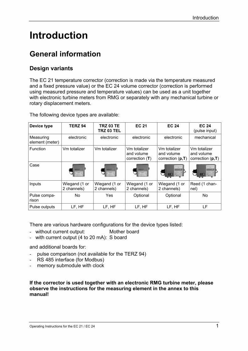
Introduction
Operating Instructions for the EC 21 EC 24 3
Program memory The program memory of the base device is located in a flash memory on the main board whereas the data memory is located on an additional board
Reset In the case of a reset the power supply is disrupted and the corrector is switched off during this period of time In this way the program and the operating parameters will not be lost and also the meter readings will be retained A reset is made on the EC 21 24 by switching off not only the battery but also a possibly available external power supply
Operating Modes
4 Operating Instructions for the EC 21 EC 24
Operating Modes Battery-powered device The EC 21 is fitted with an exchangeable battery and the EC 24 is fitted with two exchangeable batteries Both devices have been designed for a continuous operation over six years This however is conditional on the device being either read or ldquowoken uprdquo by pressing the external button once a week Battery-powered device with an external power supply If an interface submodule is used for transmitting data such as the externally supplied RS 485 the service life of the battery is more than 10 years Externally supplied device with built-in standard battery In the case of an external power supply (current transmitter which serves as a power supply and 4 to 20 mA current output at the same time) the EC 21 EC 24 is completely supplied via a current loop For this purpose a power supply unit is required which is to be connected to this output In the case of the EC 24 volume corrector pulse processing is even ensured in the event of a power failure of the current loop If pulse processing is to be maintained with the EC 21 even in the case of a power failure of the current loop a standby battery (available as an option) can be installed which will bridge the power supply during a period of up to six months Display of battery change Lithium batteries retain their voltage until they are almost completely discharged so that the voltage cannot be monitored with an appropriate display until the next battery change is necessary
Safety Instructions
Operating Instructions for the EC 21 EC 24 5
Safety Instructions The EC 21 and the EC 24 comply with currently applicable standards and regulations However failure to operate them properly may cause hazards Persons who install or operate a volume corrector in areas subject to explosion hazards must be familiar with the currently applicable explosion protection standards and regulations Do not change anything of the volume corrector on your own otherwise the approval will become invalid Operate the volume corrector only in the specified temperature range from -20degC to +60degC The electronic corrector system of the explosion-protected design has been approved for use in areas subject to explosion hazards and its code is
II 2 G EEx ib[ia] IIC T4 or T3 You can find the EC type approval certificate in the annex and its reference number is TUumlV 02 ATEX 1970 Please observe the following signs
Danger of explosion In the manual this symbol warns you of an explosion hazard Please observe the instructions given next to this symbol As to the danger of explosion please note the following in particular
bull Only the explosion-protected design of the EC 21 EC 24 may be used in areas subject to explosion hazards
Damage to property In the manual this symbol warns you of possible damage to property The instructions given next to this symbol inform you about what you can do to avoid damage to the EC 21 EC 24 volume corrector
It is essential to observe the warning information in these operating instructions and the generally applicable safety rules No warranty claims can be asserted if there is unauthorized interference with the device
Installation
6 Operating Instructions for the EC 21 EC 24
Installation Electrical connections To reach the electrical connections you must first remove the cover of the corrector
You must select the sensor inputs before you connect the cables To do this install the jumpers XS1 XS2 and XTERZ90 on the board as indicated (see inputs and outputs in the annex)
Make your settings of X_S1 and X_S2 as follows Reed contact Wiegand TERZ90
Remote totalizer EZSENS01 IG04
X5 effective X5 effective X5 effective X6_0 effective Jumpers 1-3 amp 2-4 Jumpers 3-5 amp 4-6 Jumpers 1-2 amp 3-4 All open
Controlling the start-stop totalizer or resetting the resettable totalizer (depending on the programming of the electronic totalizing unit) is performed through input X5 terminals 1 and 2 As soon as input X5 terminals 1 2 has been short-circuited through an external contact interruption or resetting is performed rArr For this purpose set jumpers at the positions identified with X_S2 to the ldquoreed contactrdquo function
Plug X2_0 for TERZ94trm current module and supply
Terminal block X4 Pulse outputs
Terminal block X15 Data interface
Sockets X151 and X152 to accommodate an interface
Plug X3 service module
Pin connector for button on the case
Plug X16_0 TERZ94p pressure sensor
Reset (soldering pads)
Terminals X5 Pulse inputs
Plug X6_0 EZSENS01
Terminals X9 PT-1000 sensor
Plug X10-0 Semiconductor temperature sensor
Configuration of pulse inputs X_S1 and X_S2 for terminals or the EZSENS01 board
Installation
Operating Instructions for the EC 21 EC 24 7
In the case of the EC 21 EC 24 terminal X22 (on TERZ94trm current module) is used as current-loop connection to supply the device and as output current (4-20 mA) The output signals can be picked up at the following terminals HF signals Output X4 terminals X44 (+) X43(-) LF signals Output X4 terminals X42 (+) X41(-) Now connect the cables and then put the cover again on the lower part of the housing To connect the cables to the spring terminals you need a screwdriver with a blade width of a maximum of 25 mm Introduce the blade into the intended slot and press down the screwdriver to open the spring terminal Standard connection pulse outputs 7-pin connector (Binder)
1 - 4 + LF signal (Vm or Vb) 2 - 5 + Fault (for all battery devices and for Ex devices with external supply) or Current output 4 to 20 mA (for non-Ex devices with external supply only) 3 - 6 + HF signal (view on device)
Standard connection interface 7-pin connector (Lumberg) 1 - 4 + RS485 supply 3 - 5 + RS485 data line 2 Spare 6 7 Calibration switch (view on device)
In areas subject to explosion hazards the EC 21 EC 24 must only be connected to certified intrinsically safe circuits Make sure that the limit values specified in the certificate of conformity (see annex) for the devices to be connected are not exceeded
If one or more than one circuit is used make sure that the permissible limit values in accordance with the EC type approval certificate are not exceeded Each intrinsically safe signal circuit must be installed in a separate cable which is to be taken through an appropriate high-strength cable gland It is absolutely imparative that the intrinsically safe cables are permanently installed Make sure that the connecting cables are provided with core-end sleeves
6
5
43
2
PE (screening)
1
7
3
542
1
6
Installation
8 Operating Instructions for the EC 21 EC 24
Earthing
To prevent measuring errors caused by electromagnetic interference you must not fail to earth the case of the meter head via the earthing screw on the left side of the case
Cables
Use 2-core or multicore shielded cables which are twisted together in pairs (type LIYCY) for the signal lines (LF output HF output current-loop connection control input) Use 4-core shielded cables which are twisted together in pairs (type LIYCY) for the data lines (RS 485) The shielding must always be connected to earth on both sides In the case of the EC 21 EC 24 you must proceed as described under ldquoCable glandsrdquo We recommend that cable cross sections of 05 mm2 are used Due to the cable gland the outside diameter must be between 45 mm and 65 mm If the device is used in areas subject to explosion hazards the maximum cable length is limited by the limit values for intrinsically safe circuits and depends on the inductance and capacitance of the cable
Minimum cable cross section Up to a length of 10 m 6 mm2 From a length of 10 m 10 mm2
Earthing screw
Installation
Operating Instructions for the EC 21 EC 24 9
Cable glands
Clamp the shielding on both sides as shown in the picture below into the cable glands located on the outside of the case
bull Unscrew the cap nut bull Pull out the plastic clamping piece bull Push the cable end through the cap nut and the clamping piece and bend the
shielding backwards bull Put the clamping piece back into the connecting piece bull Screw on the cap nut again
Permissible temperature ranges
For the standard design the following fluid temperature and ambient temperature ranges are permitted Fluid temperature range -20degC to +60degC Ambient temperature range -20degC to +60degC or 40degC
Cap nut
Clamping piece
O-ring
Connecting piece
Installation
10 Operating Instructions for the EC 21 EC 24
Installing the remote totalizer
ServicemodulTERZ94trm
TERZ94p
Impulsausgaumlnge
Datenschnittstelle
Datenschnittstelle
EZDRS-485 Boot
TP-GND
Impulseingang
X2_0
X4
X15
X9X
151
X5
CX
2
CX
3
CX6
CX
1
L1
X6_0
X152
X_S1
XLP1
Ree
d 1+
3 2
+4S
enso
rver
staumlr
ker 3
+4W
iega
nd 3
+5
4+6
4
2 6
531X_S2 X10-0
TEMP_LM7X
EZSENS01
PT1000
5313
2
1
C21
C1
V12
V13
V14
C22
Q1
X7
X16_0X1X3 Taster
RESET
X_TERZ90
S3 S1 S2 S4P
+
+-
-
4
5
61
2
3
Sensor
Sensor
ZaumlhlwerkZaumlhlwerk
-
-
+
+Index InputIndex Input
-
+
Sensor
Sensor
ZaumlhlwerkZaumlhlwerk
-
-
+
+Index InputIndex Input
-
+
Herst-NrHerst-Jahr
MESSTECHNIK GMBH35510 Butzbach
Vm3
Vm h3
Pbara
TdegC Zu
IomA
ErrorTyp Mode
Trockenes Gas im Normzust101325 bar0degC = 0Weitere Daten ldquoTyp-Schildrdquo
ϕ - 0102
Non Ex
If your model is designed for remote totalizing you can install the totalizer at a distance of up to 3 m from the meter case Usually the cable has already been connected to the sensor and the totalizing unit when the device is delivered Should this not be the case you will have to connect the connecting cable to input X5 terminals S1+ and S1- of the board If you have a 2-channel meter connect the second sensor to the clamps S2+ and S2- Use only shielded cables of the type LIYCY - 2 x 075 blue (1-channel Ex) LIYCY - 2 x 2 x 075 blue (2-channel Ex or 1-channel Non-Ex) LIYCY - 3 x 2 x 075 blue (2-channel Non-Ex) Maximum cable length 3 m
In hazardous areas the temperature transmitter must not be connected via the socket on the meter case In this case it is prescribed to lay a separate cable for the temperature transmitter
In addition check the plug-in jumpers XS1 XS2 and XTERZ90 on the board (see inputs and outputs in the annex) Make your settings of XS1 and XS2 as follows jumpers 3-4
Operation
Operating Instructions for the EC 21 EC 24 11
Operation Front panel and keyboard of the EC 24
ZuVm3 OutI
mAoT
degCP
baraV
m h3ErrorTyp
VOLUME CORRECTOREC 24
IP65
Further datapress buttons
II2G EEx ib ia IIC T3T4TUumlV 02 ATEX1970
-20degC +60degC40degC Ta EG-type examination certificate
Current output 4-20mA yes no
Ser-NoYear
MESSTECHNIK GMBHGermany
0085 0032
00123456Nm3
Keyboard Designation Effect
Arrow Down
bull Moves downwards within a list Moves from the first value of the list towards the last value
Arrow Right bull Moves to the right towards another list
Moves from the first list towards the last list
+ Function
Press both buttons at the same time to initiate the following functions Hold down gt2 sec Segment test Hold down lt 2 sec The coordinate will be displayed
If the EC 21 EC 24 is operated together with the measuring element of an electronic turbine meter the EC 21 EC 24 contains the totalizing unit of the meter and the data plate of the meter is located on the left side of the front panel
Operation
12 Operating Instructions for the EC 21 EC 24
Display In normal operating mode the main totalizer is displayed If you press the external control buttons you can select the other display values After an adjustable time has elapsed the EC 21 EC 24 will return to displaying the main totalizer If the display of the EC 21 EC 24 does not show anything the device is in energy-saving mode In this mode the display is completely switched off However incoming pulses are processed and the outputs are set If you press one of the two control buttons the display value will appear again Display switched off
Pointer position 1 0 0 0 0 5 8 3 1 m3
Main totalizer V
Pointer position 2 1 0 0 0 0 m3h Flow rate V
Pointer position 3 1 0 0 0 0 0 0 0 bara
Pressure P
Pointer position 4 20 0 0 0 0 0 0 degC
Temperature T
Pointer position 5 1 --
Conversion factor C (Analysis)
Pointer position 6 16 0 0 0 0 0 0 mA
Current Io
Pointer position 7 1 --
Error ID
Pointer position 8 1 --
Mode Memory
Operation
Operating Instructions for the EC 21 EC 24 13
Programming Via the parameterization and readout software The parameters of the EC 21 EC 24 can be changed using the parameterization and readout software The official parameters are protected by a calibration switch and a password The link between the laptop computer and the corrector is established via the RS 485 interface of the EC 21 24 Via the programming module For programming the EC 21 EC 24 there are four buttons on the bottom of the display board Alternatively you can program the device using the programming module (available as an accessory) The programming module is to be connected via a pin connector (see the picture below)
P crarr
orand
Programming with the programming module is to be performed in the same way as with the internal buttons
P + -
|rarr
Operation
14 Operating Instructions for the EC 21 EC 24
The external and internal buttons correspond to each other in the following way Int button Ext button Meaning
P P Display mode Switch over to programming mode (Press the button longer than 2 seconds) Programming mode Put the decimal point at the current position
+ and In display mode Move to the right within the matrix (change of column) In programming mode - Increase the decimal by 1 - Scroll in the list (Display value is identified by ldquoLldquo)
- or
In display mode Move towards the bottom (change of line) In programming mode - Decrease the decimal by 1 - Scroll in the list (Display value is identified by ldquoLldquo)
|rarr |rarr In display mode Short-term view of the coordinate (eg A01) In programming mode Go to the right by one decimal place (if the last decimal has been reached Quit programming mode)
Operation
Operating Instructions for the EC 21 EC 24 15
Principle of programming For programming you must always proceed as follows bull First change over to the display value to be modified
minus To do this press either the control button (only forwards) minus or the internal buttons ldquo+rdquo and ldquo-rdquo or the external buttons ldquoandrdquo and ldquoorrdquo (forwards
and backwards) bull Change to programming mode by pressing ldquoPrdquo for at least 2 seconds On the left
side of the display a flashing character or cursor will appear
0 1 2 32 3 Pm3bull You can now modify the flashing decimal by pressing either ldquo+rdquo or ldquoandrdquo (+1) or ldquo-rdquo or
ldquoorrdquo (-1) Example If you press the ldquoandldquo button three times the first decimal will be increased from 0 to 3 If an ldquoLrdquo appears on the far left side of the display this value is a list With a list you can only scroll in the specified values
bull After you have completed your programming of the first decimal press ldquo|rarr rdquo once and the next character will start to flash Now proceed with your programming until you have reached the last decimal place
bull Then press ldquo|rarrrdquo once again to have the set value accepted and quit programming mode
bull Press the ldquoPldquo button to set the decimal point behind the flashing digit With totalizers modes and integers no decimal point is permitted
bull Press the control button if you have made an error or if you want to discontinue inputting data
Display values Measured values such as the flow rate frequency etc are display values and cannot be directly modified However there are many parameters which influence the formation of these measured values These parameters are described in the following section Display values include the flow rate version number year of construction serial number value of the current output in mA for example
Flashing character
Operation
16 Operating Instructions for the EC 21 EC 24
Parameters and modes of the EC 21 EC 24 The following sections describe the meaning of the individual parameters Meter factor (pulse value) With the meter factor (pulse value) the relevant flow rate at measurement conditions is calculated from the signal frequency of the sensor element in the electronic totalizing unit
sdot=
hm3600
KfQ
3
M
f Signal frequency (Hz) K Meter factor (pulsesm3) QM Flow rate at measurement conditions (m3h) The meter factor has been calibrated in the factory in such a way that working cubic metres are directly displayed Any modification of this adjustment is within the sphere of responsibility of the operating company NOTE The new value is immediately used for all calculations performed after each modification of the meter factor The uninfluenced signal frequency of the sensor element is available at the HF output The frequency range can be determined from the meter factor K and the minimum and maximum flow rates at measurement conditions of the meter in accordance with the following formulae
K3600Qf minM
min sdot= K3600Qf maxM
max sdot=
QMmin Minimum flow rate at measurement conditions QMmax Maximum flow rate at measurement conditions K Meter factor (pulse value) Example QMmin = 16 m3h QMmax = 250 m3h K = 2362 pulsesm3
Hz510Hz2362360016fmin =sdot= Hz164Hz2326
3600250fmax =sdot=
Operation
Operating Instructions for the EC 21 EC 24 17
Totalizer factor (decimal places)
You can set the totalizer factor in coordinate Z 01 There are the following setting options
Totalizer factor Multiplier for value displayed
Decimal places
001 2 01 1 1 0 10 10 0 100 100 0
Example If the factor has been set to 01 the meter reading will be displayed with one decimal If the factor has been set to 10 the value displayed will be shown without decimals and you will obtain the actual meter reading by multiplying the value displayed by 10 Output pulse value
The output pulse value indicates how many LF output pulses correspond to one cubic metre The output pulse value can be entered in coordinate Z 02 from 001 to 100 as required
Operation
18 Operating Instructions for the EC 21 EC 24
Coordinate system
Pointer position V V P T
Designation Totalizers Flow Rate Pressure Temperature Coordinate
Line A B C D
1 Volume at base conditions Qb bara degC
2 Volume at measurement conditions Qm p min t min
3 Disturbing quantity totalizer Vb
Frequency p max t max
4 Disturbing quantity totalizer Vm Qm min pb specified value tb specified value
5 Pulse scaling factor Qm max p default t default
6 Meter factor Qm max val p binary display Factor adjustment value
7 Binary value at 05 V Offset adjustment value
8 Binary value at45 V AD binary value 9 U min
10 Monthly data memory pu min 11 Monthly data memory Rise 12 Monthly data memory Factor correction value 13 Monthly data memory Offset correction value
14 23 Monthly data memory
Pointer position
C Io Error Type Mode
Designation Analysis Outputs Error ID Mode Memory Coordinate
Line E F G Z
1 Conversion factor Current Error text TerzMode 2 K coefficient Current min Software version EcMode 3 K specified value Current max Serial number Puls_X 4 Hs Current default Checksum Puls_Y
5 Rhon Current rise Ser no pressure transmitter Time
6 CO2 Current offset p min Date 7 Zb Current damping p max Modbus address
8 Z Ser no temperature transmitter ModbusRegOffset
9 Hs ref temp T min Error bit string 10 T max Wake-up pulse 11 Ser no meter 12 Meter size 13 Battery change
Operation
Operating Instructions for the EC 21 EC 24 19
Description of individual columns Column structure
Pointer position V
Coding Coordinate Line A Description of the coordinate Unit Special feature
S 1 Nm3 Main totalizer volume at base conditions m3
S 2 m3 Main totalizer volume at measurement conditions m3
S 3 VbD Disturbing quantity totalizer volume at base conditions m3
S 4 VmD Disturbing quantity totalizer volume at measurement conditions m3
The calibration switch is realized by a jumper in the (female) interface connector For opening the calibration switch just remove the jumper Then all parameters coded with ldquoSrdquo or ldquoCrdquo can be changed
Designation of columns A to O
Press the above function key and then the key once
Unit of the value displayed or programmed
Abbreviated designation of the matrix field
Field designation shown in the display of the EC 21 EC 24
Explanatory notes on a coordinate field
Designation of the column line
Coding of the matrix fields H = Header D = Display value C = Access to a data field which is protected by the user code S = Access to a data field which is protected by the calibration switch
7
3
542
1
6
Note In the software version 10 the user code is not yet implemented To change parameters with ldquoCrdquo coding it is necessary to open the calibration switch
Operation
20 Operating Instructions for the EC 21 EC 24
Totalizers
Pointer position V
Coding Coordinate Line A Description of the coordinate Unit Special feature
S 1 Nm3 Main totalizer volume at base conditions m3
S 2 m3 Main totalizer volume at measurement conditions m3
S 3 VbD Disturbing quantity totalizer volume at base conditions m3
S 4 VmD Disturbing quantity totalizer volume at measurement conditions m3
S 5 Im3 Pulse scaling factor Im3 S 6 Im3 Meter factor Im3
D 10 23 Monthly data memory 1 14 (Date Vb Vm dVb dVm P T)
Flow rate
Pointer position V Coding Coordinate
Line B Description of the coordinate Unit Special feature
D 1 N3H Flow rate at base conditions m3h
D 2 m3h Calculated flow rate at measurement conditions m3h
D 3 F Frequency (measurement) Hz S 4 Qmlt Lower fault limit m3h S 5 Qmgt Upper fault limit m3h
D 6 Qmx Maximum value of the flow rate at measurement conditions m3h
Pressure
Pointer position P
Coding Coordinate Line C Description of the coordinate Unit Special feature
D 1 bar Measured value for pressure (absolute pressure) bara
S 2 plt Lower fault limit bara S 3 pgt Upper fault limit bara S 4 pb Specified value pressure at base conditions bara C 5 p-def Default value pressure bara D 6 Dig Pressure binary display D 7 Dig Binary value at 05 V D 8 Dig Binary value at 45 V
S 9 Umi Constant pressure transmitter base calibration V
S 10 pmi Constant pressure transmitter base calibration bara
S 11 p-S Constant pressure transmitter base calibration
S 12 pA0 Correction value pressure transmitter (factor) S 13 pA1 Correction value pressure transmitter (offset)
Operation
Operating Instructions for the EC 21 EC 24 21
Temperature
Pointer position
T
Coding Coordinate Line D Description of the coordinate Unit Special feature
D 1 degC Measured temperature value degC S 2 Tlt Lower fault limit degC S 3 Tgt Upper fault limit degC
S 4 Tb Specified value temperature at base conditions degC
C 5 T-def Default value temperature degC S 6 T-F Adjustment value (factor) S 7 T-O Adjustment value (offset) D 8 Dig Binary value of AD converter
Analysis
Pointer position C
Coding Coordinate Line E Description of the coordinate Unit Special feature
D 1 C Conversion factor 1 D 2 K K coefficient 1 C 3 K-V Specified value K coefficient (if K=const) 1 C 4 Hon Superior calorific value KWhm3 C 5 rhn Rhon Kgm3 C 6 CO2 Carbon dioxide content D 7 Zb Compressibility factor at base conditions 1
D 8 Z Compressibility factor at measurement conditions 1
S 9 TB Reference temperature superior calorific value degC
Outputs
Pointer position Io
Coding Coordinate Line F Description of the coordinate Unit Special feature
D 1 mA Current out mA C 2 Ilt Value at 4 mA mA C 3 Igt Value at 20 mA mA C 4 I-def Current default mA C 5 I-F Current rise C 6 I-O Current offset C 7 I-D Current damping
Operation
22 Operating Instructions for the EC 21 EC 24
Error ID
Pointer position Error Type
Coding Coordinate Line G Description of the coordinate Unit Special feature
D 1 ERR Error text D 2 Ver Software version S 3 SNo Serial number D 4 CRC Checksum
S 5 PNo Serial number pressure transmitter
S 6 P lt Pressure range min bar S 7 P gt Pressure range max bar
S 8 TNo Serial number temperature transmitter
S 9 T lt Temperature range min degC S 10 T gt Temperature range max degC S 11 ZNo Serial number gas meter S 12 G Meter size S 13 Bat Date of next battery change
Mode Memory
Pointer position Mode Coding Coordinate
Line Z Description of the coordinate Unit Special feature
C 1 MOD TerzMode See operating modes C 2 MOD EcMode See operating modes C 3 X Puls_ X C 4 Y Puls_ Y C 5 T Time C 6 D Date C 7 Mid Modbus address C 8 Mof Modbus register offset C 9 Err Error bit string (hexadecimal) D 10 Pul Wake-up pulse
TerzMode and EcMode are 8-digit strings where each digit stands for one mode These modes are listed in the following tables
Operation
Operating Instructions for the EC 21 EC 24 23
Operating modes
0 1 2 3 4 5 6 7 8 9 0 1 2 3 4 5 6 7 8 9
Terz
Mod
e[7]
Ope
ratin
g m
ode
1 ch
anne
l
1 ch
anne
l Vm
Sto
p
1 ch
anne
l Vm
Run
2 ch
anne
ls
XY
act
(S
W) V
m S
top
2 ch
anne
ls
XY
act
(S
W) V
m R
un
2 ch
anne
ls
XY
act
(H
W) V
m S
top
2 ch
anne
ls
XY
act
(H
W) V
m R
un
2 ch
anne
ls
XY
dea
ctiv
ated
EcM
ode[
7]
Freq
uenc
y m
ode
off
pos
edg
e
neg
edg
e
Terz
Mod
e[6]
Cur
rent
out
put
off
Iout
with
out e
rror
Iout
35
mA
with
err
or
Iout
21
8 m
A w
ith e
rror
EcM
ode[
6]
Dat
a lo
gger
m
ode
Off
Vb
Vm d
Vb
dVm p
T
Terz
Mod
e[5]
Puls
e sc
alin
g fa
ctor
001
01 1 10
100
EcM
ode[
5]
Ana
lysi
s m
ode
K=c
onst
GE
RG
AG
A
Terz
Mod
e[4]
Inte
rfac
e pr
otoc
ol
off
Mod
bus
EcM
ode[
4]
Puls
e w
idth
LF
-II
08
ms
10 m
s
20 m
s
50 m
s
75 m
s
100
ms
125
ms
250
ms
Terz
Mod
e (c
oord
inat
e Z1
) Te
rzM
ode[
3]
Dis
play
cu
t-off
time
1 m
in
5 m
in
10 m
in
15 m
in
test
mod
e
EcM
ode
(coo
rdin
ate
Z2)
EcM
ode[
3]
LF
sele
ctio
n
Vm
Vb
Terz
Mod
e[2]
Puls
e w
idth
LF
out
put
125
ms
250
ms
EcM
ode[
2]
Cur
rent
se
lect
ion
off
defa
ult
Qm
Qb
tem
p
pres
sure
Terz
Mod
e[1]
Uni
ts
m3
bar
degC
cf
EcM
ode[
1]
Tem
pera
ture
m
ode
off
PT
1000
defa
ult
Terz
Mod
e[0]
Inte
rnal
cust
omer
serv
ice
clea
r Qm
max
all c
oord
on
EcM
ode[
0]
Pres
sure
m
ode
off
on
defa
ult
0 1 2 3 4 5 6 7 8 9 0 1 2 3 4 5 6 7 8 9
Operation
24 Operating Instructions for the EC 21 EC 24
Error messages In coordinate G 01 error messages are displayed as error number followed by ldquoErrrdquo The messages no 1 to 8 are fault messages In this case the main totalizers stop and the disturbing quantity totalizers start to run The messages no 9 to 16 are warnings and have no effect on the totalizers
Error no Hexadecimal Description 1 0x0001 Parameters in EEPROM are wrong (may be wrong version) 2 0x0002 EEPROM can not be written (parameters are lost) 3 0x0004 Analog digital converter for temperature measurement 4 0x0008 Analog digital converter for pressure measurement 5 0x0010 - 6 0x0020 Measured temperature outside limits 7 0x0040 Measured pressure outside limits 8 0x0080 Hardware and software configuration do not fit 9 0x0100 -
10 0x0200 - 11 0x0400 - 12 0x0800 - 13 0x1000 Current output 14 0x2000 Too many output pulses in buffer (gt500) 15 0x4000 Sensor defect (check hardware) 16 0x8000 Sensor defect (check hardware)
In the column ldquoHexadecimalrdquo the error bit strings displayed in coordinate Z 09 are listed
Operation
Operating Instructions for the EC 21 EC 24 25
Changing the batteries (EC 24) The two batteries of the EC 24 can easily be changed without opening the corrector On the left side of the casing there is a round slotted cover which can be screwed out Behind this cover there is the battery holder In hazardous areas disconnect the battery holder and change the batteries in a safe area Afterwards connect the battery holder again (see figure) and push it into the battery compartment Now screw in the cover again and the battery change is terminated In safe areas the batteries can be changed directly without disconnecting the battery holder
If you use other batteries than the replacement batteries from RMG you run the risk of the EC 24 not being approved for areas subject to explosion hazards any more In areas subject to explosion hazards you must never insert or remove the batteries Remove the battery holder from the case and change the batteries in an area without explosion hazards
redbluebluered
Annex A Equations
26 Operating Instructions for the EC 21 EC 24
Annexes A Equations used with the EC 21 temperature corrector and
the EC 24 volume corrector Symbol Unit Designation qm = m3h Flow rate at measurement conditions fv = Hz Frequency of the volume transducer KV = Pm3 Meter factor Vm = m3 Volume at measurement conditions Pv = 1 Volume pulse KZ1 = m3P Totalizer factor (for output contacts only) qb = m3h Flow rate at base conditions Vb = m3 Volume at base conditions C(pt) = 1 Conversion factor KZ2 = m3P Totalizer factor (for output contacts only) p = bara (Absolute) pressure at measurement conditions (barg kgcm2) pb = bara Pressure at base conditions (barg kgcm2) (= 101325 bar absolute) T = degC Temperature at measurement conditions TK = K Temperature at measurement conditions in Kelvin Tb = K Temperature at base conditions (= 27315 K) K = 1 K coefficient Z = 1 Compressibility factor at measurement conditions Zb = 1 Compressibility factor at base conditions Z and Zb are calculated in compliance with GERG-88 as
per G9
Annex A Equations
Operating Instructions for the EC 21 EC 24 27
Flow rate at measurement conditions
3600Kf =q
V
Vm sdot
Volume at measurement conditions
Z1V
Vm K
1KP =V sdot
K coefficient
bZ
Z =K
Conversion factor
KTp
T p =C
Kb
bt)(p sdotsdot
sdot
Flow rate at base conditions
3600CKf = q
V
Vb sdotsdot
Volume at base conditions
Z2
t)(pmb K1C V= V sdotsdot
The pressure at measurement or base conditions is processed as absolute pressure in the relevant equations In selection mode 2 of column A however transmitters with gauge-pressure or kgcm2 scaling are also permitted If these transmitters are used the pressure at base conditions must also be indicated in the appropriate unit Both the pressure at measurement conditions and the pressure at base conditions will then be converted automatically for the relevant equations
Annex B Block diagram
28 Operating Instructions for the EC 21 EC 24
B Block diagram for the EC 21 EC 24
UP
88888888
Ree
d sw
itch
or Wie
gand
sen
sor
Pres
sure
tr
ansm
itter
Onl
y EC
24
Tem
pera
ture
sen
sor
PT 1
000
Puls
e co
mpa
rison
EZD
or R
S485
Cur
rent
mod
ule
Mem
ory+
Prin
t+C
lock TE
RZ
94
Key
boar
d
RS
485
(Mod
bus)
4 to
20
mA
Faul
tH
FLF
(Vb
or V
m)
8-di
git d
ispl
ay
Bat
tery
36
V
Inpu
tsC
orre
ctio
nO
utpu
ts
Pulseinput
Serialinterface
Currentoutput
Signaloutput
Analoginput
Analoginput
Annex C Specifications
Operating Instructions for the EC 21 EC 24 29
C Specifications
Temperature ranges Type EC 21 24 II2 G EEx ib IIC T4 from -20degC to +40degC II2 G EEx ib IIC T3 from -20degC to +60degC In the case of special designs even higher or lower fluid temperatures are possible with not explosion-protected (Non-Ex) versions
Device types Reed Supply Internal battery (Ex)
or external 24 V supply via current-loop connection by means of a power supply unit of the type KFD2-STC3-Ex1 (Ex) plus battery pack
Pulse input Reed or transistor Current output Only possible via the current-loop connection Standby battery Only in conjunction with the current-loop connection Wiegand Use Direct installation onto the TERZ 91 meter instead of the
meter head Supply Internal battery (Ex)
or external 24 V supply via current-loop connection by means of a power supply unit of the type KFD2-STC3-Ex1 (Ex) plus battery pack
Pulse input Wiegand Current output Only possible via the current-loop connection Standby battery Only in conjunction with the current-loop connection
Annex C Specifications
30 Operating Instructions for the EC 21 EC 24
Inputs Volume ndash Reed
Pulse frequency 0 Hz to 20 Hz in battery-powered mode max 1 Hz due to the service life
Pulse width ge 20 ms Voltage low le 09 V high ge 22 V
ndash Wiegand Pulse frequency 0 Hz to 300 Hz in battery-powered mode Pulse width ge 5 micros Voltage min 1 V max 5 V (depends on the sensor used)
Sensor ndash S1 input (Measurement input) (For Ex connected loads see the approval certificate) Terminals X51 (+) X52 (-) Sensor type Wiegand sensor direct Length of line lt 50 cm Jumpers X_S1 3-5 and 4-6 Wiegand sensor remote totalizer Length of line lt 50m Jumpers X_S1 3-5 and 4-6 Jumpers X_TERZ90 1-2 Reed contact Jumpers X_S1 1-3 and 2-4
Sensor ndash S2 input (Reference input or startstopreset)
(For Ex connected loads see the approval certificate) Terminals X53 (+) X54 (-) Sensor type Wiegand sensor direct Length of line lt 50 cm Jumpers X_S1 3-5 and 4-6 Wiegand sensor remote totalizer Length of line lt 50m Jumpers X_S2 3-5 and 4-6 Jumpers X_TERZ90 3-4 Reed contact Jumpers X_S2 1-3 and 2-4
Annex C Specifications
Operating Instructions for the EC 21 EC 24 31
Temperature input (hardware and software option) For Ex connected loads see the approval certificate Signal Resistor (Pt1000) 4-wire Terminals X91 (+) X92 (-) Measuring range -20degC to 60degC Resolution plusmn 02 degC Pressure transmitter
For Ex connected loads see the approval certificate Signal Voltage 05 V to 45 V Resolution 16 bits Terminals Plug X16_0
Annex C Specifications
32 Operating Instructions for the EC 21 EC 24
Outputs
HF output
In the case of the explosion-protected (Ex) design the device can only be connected to a certified intrinsically safe circuit Terminals X44 (+) X43 (-)
Output Open-drain transistor TPulse 1 ms plusmn 10 Fmax 300 Hz
Ex Non-Ex Umin 20 V 20 V Umax 28 V 30 V Imax 60 mA 400 mA External inductance 1 H External capacitance 25 microF LF output
In the case of the explosion-protected (Ex) design the device can only be connected to a certified intrinsically safe circuit (For Ex connected loads see the approval certificate) Terminals X42 (+) X41 (-) Output Open-drain transistor TPulse 125 ms plusmn 10 (Fmax 4 Hz) 250 ms plusmn 10 (Fmax 2 Hz)
Ex Non-Ex Umin 20 V 20 V Umax 28 V 30 V Imax 60 mA 400 mA External inductance 1 H External capacitance 25 microF
Annex C Specifications
Operating Instructions for the EC 21 EC 24 33
Fault output
In the case of the explosion-protected (Ex) design the device can only be connected to a certified intrinsically safe circuit (For Ex connected loads see the approval certificate) Terminals X46 (+) X45 (-) Output Open-drain transistor Ex Non-Ex Umin 20 V 20 V Umax 28 V 30 V Imax 60 mA 400 mA External inductance 1 H External capacitance 25 microF
Annex C Specifications
34 Operating Instructions for the EC 21 EC 24
Vo or RS-485 data interface
In the case of the explosion-protected (Ex) design the device can only be connected to a certified intrinsically safe circuit (For Ex connected loads see the approval certificate) Vo data interface Internal connector (from Binder) Parity Even Data bits 7 Stop bit 1 Baud rate 2400 Terminals X154 (+) 4 X153 (-) 1 X151 and X152 open Umin 70 V Ui 135 V Ii 15 mA Pi 210 mW External capacitance 25 microF External inductance 1 H Isolating device KFD2-ST2-Ex1LB (from Pepperl+Fuchs) RS-485 data interface Terminals X154 (+ supply) X153 (- supply) X152 (line A) X151 (line B) Umin 70 V Ui 105 V Ii 428 mA Pi 900 mW Inner capacitance 132 microF Inner self-inductance 600 microH External capacitance 237 microF External inductance 1 H Isolating device 17-21S1-S111 EExi (from Bartec) Note If the EZD protocol or the RS-485 bus is used the device is supplied via the data interface
Annex C Specifications
Operating Instructions for the EC 21 EC 24 35
Current-loop connection
Terminals X221 (+) X222 (-) Uext (min) 12 V Uext (max) 28 V Imin 35 mA Imax 23 mA External load (max) RLmax = (Uext - 10 V) Imax (in Ω) eg Uext = 16 V rArr RLmax = (16 V - 10 V) 23 mA = 260 Ω Current output for - minimum flow rate 4 mA - maximum flow rate 20 mA - warning 35 mA - fault 23 mA Accuracy of current output Better than 1 of the upper-range value Data for use in areas subject to explosion hazards Ui = 28 V Ii = 110 mA Pi = 770 mW Ci = 22 nF Li = 110 microF Supply Battery supply 36 V lithium cell inside the device (battery pack) External 24 V supply 24 V DC external via current-loop connection plus battery pack
Annex D Examples of connection
36 Operating Instructions for the EC 21 EC 24
D Examples of connection (EC 21 and EC 24)
Battery-powered device
Isolating deviceBARTEC Type Sekopia
Hazardous area Safe Area
ConnectorLumberg Series 0332
ConnectorBinder Series 693
PC
Equipotential bonding
Isolating amplifiersKFD2-SOT-Ex2 (24 VDC)
RS 485LIYCY 2x2x05 mm blue2
Pulse outputsLIYCY 3x2x075 mm blue2
X41 2 3 4 5 6
24 VDCPE N L1
6
6
6
5
5
5
7
9
7
11
11
11
12
12
12
PE
PE
PE
8
10
8
X151 2 3 4
BAVo-
Vo+
Fault
HF
LF
Annex D Examples of connection
Operating Instructions for the EC 21 EC 24 37
Mains-powered device (Connection only via a current module with built-in back-up battery)
Isolating deviceBARTEC Type Sekopia
Hazardous area Safe area
ConnectorLumberg Series 0332
ConnectorBinder Series 693
PC
Equipotential bonding
Isolating amplifiersKFD2-SOT-Ex2 (24 VDC)
Supply unitKFD2-STC3-Ex1 (24 VDC)orKFD2-CR-Ex120300 (24 VDC)
RS 485LIYCY 2x2x05 mm blue2
Pulse outputsLIYCY 3x2x075 mm blue2
X41 2 3 4 5 6
24 VDCPE N L1
6
6
6
5
5
5
7
9
7
11
11
11
12
12
12
PE
PE
PE
8
10
8
X151 2 3 4
BAVo-
Vo+
Fault
HF
LF
Annex E Instructions for the measuring element of the turbine meter
38 Operating Instructions for the EC 21 EC 24
E Instructions for the measuring element of the turbine meter
Construction
Part Designation Material 1 Totalizing unit 2 Clamping screw Steel 3 WF01 or WF02 sensor 4 Permanent magnet Oerstit 500 5 Lubricator
(with TERZ 94 from DN 200)
6 Radial ball bearing Nirosta steel 7 Turbine wheel Delrin aluminium 8 Flow straightener Hostaform 9 O-ring 10 Sensor sleeve with sensor Nirosta steel 11 O-ring 8x25 83FKM592
1
11 2
3
10
9
8 4
7 6 5
Electronic totalizing unit or corrector
WF01WF02 sensor
Measuring element
Annex E Instructions for the measuring element of the turbine meter
Operating Instructions for the EC 21 EC 24 39
Functional description The measuring element directly measures the flow rate at measurement conditions and in the top-mounted meter head or corrector the measured values are integrated so that the result is the gas volume which flowed through the meter The gas flow drives a turbine wheel whose speed is recorded through non-contact measurement by a sensor Therefore the meter is characterized by long-term stability and low wear An aerodynamic flow straightener (8) fitted into the meter case constricts the effective cross section of the pipe to form a ring-shaped cross-sectional area and substantially eliminates turbulence The velocity of the flowing gas increases and the gas is directed to the turbine blades The turbine wheel (7) is dynamically balanced and mounted with dust-proof ball bearings (6) A permanent magnet (4) located at the end plate of the turbine shaft induces the sensor element (3) to give a voltage pulse with each rotation of the turbine wheel This pulse is further processed by the electronic system of the meter head (1) Inside the meter head or corrector the number of pulses is divided by the meter factor (number of pulses per m3) and the result is used to calculate the volume at measurement conditions In the main totalizer the sum of the volume at measurement conditions which flowed through the meter is formed and you can read the gas volume which flowed through the meter per time unit on the flow rate display At the HF output (only in the case of an electronic measuring element) the unchanged signal frequency of the sensor element is outputted whereas for the LF output this HF frequency can be reduced by two programmable scaling factors Operating conditions Permissible types of gases The standard design of the TRZ 03 ndash TE TEL turbine meters can be used for all non-aggressive gases such as
Natural gas Air Town gas Acetylene Methane Helium Ethane Carbon dioxide (dry) Propane Nitrogen Butane Hydrogen
Special designs (PTFE lining special lubrication special material etc) can be used for aggressive and humid gases such as
Ethylene Digester gas Biogas Sulphur dioxide Acid gas etc
Annex E Instructions for the measuring element of the turbine meter
40 Operating Instructions for the EC 21 EC 24
Permissible temperature ranges For the standard design the following fluid temperature and ambient temperature ranges are permitted Fluid temperature range -20degC to +60degC For the ambient temperature range see the ID plate and Annex C on page 28
Pressure loss The pressure loss is calculated using the following formula
4
2M
P DNQ
Z=p sdotρsdot∆
where ∆p is the pressure loss [mbar] ZP is the pressure loss coefficient ρ is the density [kgm3] QM is the flow rate at measurement conditions [m3h] DN is the nominal diameter of the meter [mm] The pressure loss coefficient ZP is ZP = 5040 (TERZ 94 TRZ 03-TE) ZP = 6050 (TRZ 03-TEL) This is an approximate mean value The exact value is calculated from the pressure loss which is determined on testing the volumeter Example of calculation QM = 650 m3h DN 150 ρ = 13 kgm3 [natural gas 600 mbar]
mbar55150650315040
DNQZ=p 4
2M
P 4
2
=sdotsdot=sdotρsdot∆
Therefore the pressure loss ∆p with a TERZ 94 or TRZ 03-TE turbine meter is 55 mbar in this case
Installation The gas flow must be free of shocks and pulsations as well as free of foreign particles dust and liquids Any components affecting the gas flow must absolutely be avoided directly upstream of the TERZ 94 or TRZ 03-TE turbine meter To achieve the highest possible accuracy the following inlet pipe is to be installed upstream of the meter TERZ 94 length of 2 DN with one perforated-plate straightener TRZ 03-TE length of 2 DN (specified by Technical Guideline G 13) TRZ 03-TEL no inlet pipe required
Annex E Instructions for the measuring element of the turbine meter
Operating Instructions for the EC 21 EC 24 41
In the case of the TERZ 94 you can install the meters in any position (vertical or horizontal) up to and including the nominal diameter of DN 200 From the nominal diameter of DN 250 and in the case of the TRZ 03-TE TEL only the position stated in the purchase order is possible When you install the meter please observe the direction of flow indicated on the case The meter head (1) can be turned after the clamping screw (2) has been loosened Turn the meter head by max 360deg otherwise the signal wires can become twisted and break Start-up Connecting the gas flow
Do not fill any downstream pipelines or station sections through the TERZ 94 or TRZ 03 ndash TE TEL turbine meters This may speed up the turbine wheel and lead to excessively high flow rates with resultant damage
Short-time overload operation of 20 above the maximum flow rate Qmax is permissible No damage will occur in the case of a return flow without shocks Initializing the device Set all totalizers to the meter reading of your choice (See programming) Now check the settings of the pulse width decade scalers etc In the case of models with a current output Also check the settings of the current output NOTE All parameters can only be changed if the device has been opened
Annex F Dimensions
42 Operating Instructions for the EC 21 EC 24
Annex F Dimensions
Drwg noMESSTECHNIK GMBH35510 Butzbach
140150
120 45
140
H1
80 80
volumeterPT-correctortype EVC 24
Dimensions
0581474
Pr
EC24
Flow direction from left to right
Flow direction from right to leftStandard installation
TERZ meter(flange-design)
display
Pr
display
Oslash 6 x 1
Oslash 6 x 1
pipe no 1
pipe no 2
DN H1 25 190 40 190 50 225 80 260100 265150 295200 325250 370300 385400 375500 395
Annex G Operating instructions for the installer
Operating Instructions for the EC 21 EC 24 43
Annex G Operating instructions for the installer Identification
Type EC 21 EC 24 II 2 G EEx ib IIC T4 andor T3 TUumlV 02 ATEX 1970 Temp= -20degC+40degC andor +60degC Data see EC type approval certificate Year of construction 2004 Serial number xxxx xx 0032
Manufacturer RMG Messtechnik GmbH Otto ndash Hahn ndash Straszlige 5 D-35510 Butzbach Application
The device EC 21EC 24 is equipment for hazardous area Assemblydisassembly
When assembling it is to be made sure that the degree of protection of the case is kept A direct exposure to sun must be avoided In case of disassembly the signal circuits are to be switched to zero potential and the corresponding cables are to be removed
Installation
If one or more circuits are used it is to be made sure with the cable selection that the permissible limiting values according to the EC type approval certificate are not exceeded Each Ex signal circuit is to be run in its own cable which has to be lead through the appropriate PG cable gland A fixed laying of the intrinsically safe cables is obligatory The connecting cables are to be provided with core-end sleeves
Annex G Operating instructions for the installer
44 Operating Instructions for the EC 21 EC 24
Start-up
With the start-up of this device it is to be made sure that all cables in the clamp area are correctly connected and run The case must be completely closed With the installation and start-up the standard EN60079-14 is to be observed The device may be started up only by persons after training
Settings
The basic setting of the device takes place by RMG Messtechnik Changes of the basic setting may only be carried out by persons after training andor instruction
Maintenance
The battery changes may only take place in a safe area Repairs at this device may be carried out by RMG Messtechnik only
Safety instructions
The manual must be accessible to all persons who are authorized with the operation of the device No arbitrary changes may be made at the device since otherwise the approval becomes invalid The device may be never opened by force The warning references in this manual and the generally accepted safety rules must be observed

Installation
8 Operating Instructions for the EC 21 EC 24
Earthing
To prevent measuring errors caused by electromagnetic interference you must not fail to earth the case of the meter head via the earthing screw on the left side of the case
Cables
Use 2-core or multicore shielded cables which are twisted together in pairs (type LIYCY) for the signal lines (LF output HF output current-loop connection control input) Use 4-core shielded cables which are twisted together in pairs (type LIYCY) for the data lines (RS 485) The shielding must always be connected to earth on both sides In the case of the EC 21 EC 24 you must proceed as described under ldquoCable glandsrdquo We recommend that cable cross sections of 05 mm2 are used Due to the cable gland the outside diameter must be between 45 mm and 65 mm If the device is used in areas subject to explosion hazards the maximum cable length is limited by the limit values for intrinsically safe circuits and depends on the inductance and capacitance of the cable
Minimum cable cross section Up to a length of 10 m 6 mm2 From a length of 10 m 10 mm2
Earthing screw
Installation
Operating Instructions for the EC 21 EC 24 9
Cable glands
Clamp the shielding on both sides as shown in the picture below into the cable glands located on the outside of the case
bull Unscrew the cap nut bull Pull out the plastic clamping piece bull Push the cable end through the cap nut and the clamping piece and bend the
shielding backwards bull Put the clamping piece back into the connecting piece bull Screw on the cap nut again
Permissible temperature ranges
For the standard design the following fluid temperature and ambient temperature ranges are permitted Fluid temperature range -20degC to +60degC Ambient temperature range -20degC to +60degC or 40degC
Cap nut
Clamping piece
O-ring
Connecting piece
Installation
10 Operating Instructions for the EC 21 EC 24
Installing the remote totalizer
ServicemodulTERZ94trm
TERZ94p
Impulsausgaumlnge
Datenschnittstelle
Datenschnittstelle
EZDRS-485 Boot
TP-GND
Impulseingang
X2_0
X4
X15
X9X
151
X5
CX
2
CX
3
CX6
CX
1
L1
X6_0
X152
X_S1
XLP1
Ree
d 1+
3 2
+4S
enso
rver
staumlr
ker 3
+4W
iega
nd 3
+5
4+6
4
2 6
531X_S2 X10-0
TEMP_LM7X
EZSENS01
PT1000
5313
2
1
C21
C1
V12
V13
V14
C22
Q1
X7
X16_0X1X3 Taster
RESET
X_TERZ90
S3 S1 S2 S4P
+
+-
-
4
5
61
2
3
Sensor
Sensor
ZaumlhlwerkZaumlhlwerk
-
-
+
+Index InputIndex Input
-
+
Sensor
Sensor
ZaumlhlwerkZaumlhlwerk
-
-
+
+Index InputIndex Input
-
+
Herst-NrHerst-Jahr
MESSTECHNIK GMBH35510 Butzbach
Vm3
Vm h3
Pbara
TdegC Zu
IomA
ErrorTyp Mode
Trockenes Gas im Normzust101325 bar0degC = 0Weitere Daten ldquoTyp-Schildrdquo
ϕ - 0102
Non Ex
If your model is designed for remote totalizing you can install the totalizer at a distance of up to 3 m from the meter case Usually the cable has already been connected to the sensor and the totalizing unit when the device is delivered Should this not be the case you will have to connect the connecting cable to input X5 terminals S1+ and S1- of the board If you have a 2-channel meter connect the second sensor to the clamps S2+ and S2- Use only shielded cables of the type LIYCY - 2 x 075 blue (1-channel Ex) LIYCY - 2 x 2 x 075 blue (2-channel Ex or 1-channel Non-Ex) LIYCY - 3 x 2 x 075 blue (2-channel Non-Ex) Maximum cable length 3 m
In hazardous areas the temperature transmitter must not be connected via the socket on the meter case In this case it is prescribed to lay a separate cable for the temperature transmitter
In addition check the plug-in jumpers XS1 XS2 and XTERZ90 on the board (see inputs and outputs in the annex) Make your settings of XS1 and XS2 as follows jumpers 3-4
Operation
Operating Instructions for the EC 21 EC 24 11
Operation Front panel and keyboard of the EC 24
ZuVm3 OutI
mAoT
degCP
baraV
m h3ErrorTyp
VOLUME CORRECTOREC 24
IP65
Further datapress buttons
II2G EEx ib ia IIC T3T4TUumlV 02 ATEX1970
-20degC +60degC40degC Ta EG-type examination certificate
Current output 4-20mA yes no
Ser-NoYear
MESSTECHNIK GMBHGermany
0085 0032
00123456Nm3
Keyboard Designation Effect
Arrow Down
bull Moves downwards within a list Moves from the first value of the list towards the last value
Arrow Right bull Moves to the right towards another list
Moves from the first list towards the last list
+ Function
Press both buttons at the same time to initiate the following functions Hold down gt2 sec Segment test Hold down lt 2 sec The coordinate will be displayed
If the EC 21 EC 24 is operated together with the measuring element of an electronic turbine meter the EC 21 EC 24 contains the totalizing unit of the meter and the data plate of the meter is located on the left side of the front panel
Operation
12 Operating Instructions for the EC 21 EC 24
Display In normal operating mode the main totalizer is displayed If you press the external control buttons you can select the other display values After an adjustable time has elapsed the EC 21 EC 24 will return to displaying the main totalizer If the display of the EC 21 EC 24 does not show anything the device is in energy-saving mode In this mode the display is completely switched off However incoming pulses are processed and the outputs are set If you press one of the two control buttons the display value will appear again Display switched off
Pointer position 1 0 0 0 0 5 8 3 1 m3
Main totalizer V
Pointer position 2 1 0 0 0 0 m3h Flow rate V
Pointer position 3 1 0 0 0 0 0 0 0 bara
Pressure P
Pointer position 4 20 0 0 0 0 0 0 degC
Temperature T
Pointer position 5 1 --
Conversion factor C (Analysis)
Pointer position 6 16 0 0 0 0 0 0 mA
Current Io
Pointer position 7 1 --
Error ID
Pointer position 8 1 --
Mode Memory
Operation
Operating Instructions for the EC 21 EC 24 13
Programming Via the parameterization and readout software The parameters of the EC 21 EC 24 can be changed using the parameterization and readout software The official parameters are protected by a calibration switch and a password The link between the laptop computer and the corrector is established via the RS 485 interface of the EC 21 24 Via the programming module For programming the EC 21 EC 24 there are four buttons on the bottom of the display board Alternatively you can program the device using the programming module (available as an accessory) The programming module is to be connected via a pin connector (see the picture below)
P crarr
orand
Programming with the programming module is to be performed in the same way as with the internal buttons
P + -
|rarr
Operation
14 Operating Instructions for the EC 21 EC 24
The external and internal buttons correspond to each other in the following way Int button Ext button Meaning
P P Display mode Switch over to programming mode (Press the button longer than 2 seconds) Programming mode Put the decimal point at the current position
+ and In display mode Move to the right within the matrix (change of column) In programming mode - Increase the decimal by 1 - Scroll in the list (Display value is identified by ldquoLldquo)
- or
In display mode Move towards the bottom (change of line) In programming mode - Decrease the decimal by 1 - Scroll in the list (Display value is identified by ldquoLldquo)
|rarr |rarr In display mode Short-term view of the coordinate (eg A01) In programming mode Go to the right by one decimal place (if the last decimal has been reached Quit programming mode)
Operation
Operating Instructions for the EC 21 EC 24 15
Principle of programming For programming you must always proceed as follows bull First change over to the display value to be modified
minus To do this press either the control button (only forwards) minus or the internal buttons ldquo+rdquo and ldquo-rdquo or the external buttons ldquoandrdquo and ldquoorrdquo (forwards
and backwards) bull Change to programming mode by pressing ldquoPrdquo for at least 2 seconds On the left
side of the display a flashing character or cursor will appear
0 1 2 32 3 Pm3bull You can now modify the flashing decimal by pressing either ldquo+rdquo or ldquoandrdquo (+1) or ldquo-rdquo or
ldquoorrdquo (-1) Example If you press the ldquoandldquo button three times the first decimal will be increased from 0 to 3 If an ldquoLrdquo appears on the far left side of the display this value is a list With a list you can only scroll in the specified values
bull After you have completed your programming of the first decimal press ldquo|rarr rdquo once and the next character will start to flash Now proceed with your programming until you have reached the last decimal place
bull Then press ldquo|rarrrdquo once again to have the set value accepted and quit programming mode
bull Press the ldquoPldquo button to set the decimal point behind the flashing digit With totalizers modes and integers no decimal point is permitted
bull Press the control button if you have made an error or if you want to discontinue inputting data
Display values Measured values such as the flow rate frequency etc are display values and cannot be directly modified However there are many parameters which influence the formation of these measured values These parameters are described in the following section Display values include the flow rate version number year of construction serial number value of the current output in mA for example
Flashing character
Operation
16 Operating Instructions for the EC 21 EC 24
Parameters and modes of the EC 21 EC 24 The following sections describe the meaning of the individual parameters Meter factor (pulse value) With the meter factor (pulse value) the relevant flow rate at measurement conditions is calculated from the signal frequency of the sensor element in the electronic totalizing unit
sdot=
hm3600
KfQ
3
M
f Signal frequency (Hz) K Meter factor (pulsesm3) QM Flow rate at measurement conditions (m3h) The meter factor has been calibrated in the factory in such a way that working cubic metres are directly displayed Any modification of this adjustment is within the sphere of responsibility of the operating company NOTE The new value is immediately used for all calculations performed after each modification of the meter factor The uninfluenced signal frequency of the sensor element is available at the HF output The frequency range can be determined from the meter factor K and the minimum and maximum flow rates at measurement conditions of the meter in accordance with the following formulae
K3600Qf minM
min sdot= K3600Qf maxM
max sdot=
QMmin Minimum flow rate at measurement conditions QMmax Maximum flow rate at measurement conditions K Meter factor (pulse value) Example QMmin = 16 m3h QMmax = 250 m3h K = 2362 pulsesm3
Hz510Hz2362360016fmin =sdot= Hz164Hz2326
3600250fmax =sdot=
Operation
Operating Instructions for the EC 21 EC 24 17
Totalizer factor (decimal places)
You can set the totalizer factor in coordinate Z 01 There are the following setting options
Totalizer factor Multiplier for value displayed
Decimal places
001 2 01 1 1 0 10 10 0 100 100 0
Example If the factor has been set to 01 the meter reading will be displayed with one decimal If the factor has been set to 10 the value displayed will be shown without decimals and you will obtain the actual meter reading by multiplying the value displayed by 10 Output pulse value
The output pulse value indicates how many LF output pulses correspond to one cubic metre The output pulse value can be entered in coordinate Z 02 from 001 to 100 as required
Operation
18 Operating Instructions for the EC 21 EC 24
Coordinate system
Pointer position V V P T
Designation Totalizers Flow Rate Pressure Temperature Coordinate
Line A B C D
1 Volume at base conditions Qb bara degC
2 Volume at measurement conditions Qm p min t min
3 Disturbing quantity totalizer Vb
Frequency p max t max
4 Disturbing quantity totalizer Vm Qm min pb specified value tb specified value
5 Pulse scaling factor Qm max p default t default
6 Meter factor Qm max val p binary display Factor adjustment value
7 Binary value at 05 V Offset adjustment value
8 Binary value at45 V AD binary value 9 U min
10 Monthly data memory pu min 11 Monthly data memory Rise 12 Monthly data memory Factor correction value 13 Monthly data memory Offset correction value
14 23 Monthly data memory
Pointer position
C Io Error Type Mode
Designation Analysis Outputs Error ID Mode Memory Coordinate
Line E F G Z
1 Conversion factor Current Error text TerzMode 2 K coefficient Current min Software version EcMode 3 K specified value Current max Serial number Puls_X 4 Hs Current default Checksum Puls_Y
5 Rhon Current rise Ser no pressure transmitter Time
6 CO2 Current offset p min Date 7 Zb Current damping p max Modbus address
8 Z Ser no temperature transmitter ModbusRegOffset
9 Hs ref temp T min Error bit string 10 T max Wake-up pulse 11 Ser no meter 12 Meter size 13 Battery change
Operation
Operating Instructions for the EC 21 EC 24 19
Description of individual columns Column structure
Pointer position V
Coding Coordinate Line A Description of the coordinate Unit Special feature
S 1 Nm3 Main totalizer volume at base conditions m3
S 2 m3 Main totalizer volume at measurement conditions m3
S 3 VbD Disturbing quantity totalizer volume at base conditions m3
S 4 VmD Disturbing quantity totalizer volume at measurement conditions m3
The calibration switch is realized by a jumper in the (female) interface connector For opening the calibration switch just remove the jumper Then all parameters coded with ldquoSrdquo or ldquoCrdquo can be changed
Designation of columns A to O
Press the above function key and then the key once
Unit of the value displayed or programmed
Abbreviated designation of the matrix field
Field designation shown in the display of the EC 21 EC 24
Explanatory notes on a coordinate field
Designation of the column line
Coding of the matrix fields H = Header D = Display value C = Access to a data field which is protected by the user code S = Access to a data field which is protected by the calibration switch
7
3
542
1
6
Note In the software version 10 the user code is not yet implemented To change parameters with ldquoCrdquo coding it is necessary to open the calibration switch
Operation
20 Operating Instructions for the EC 21 EC 24
Totalizers
Pointer position V
Coding Coordinate Line A Description of the coordinate Unit Special feature
S 1 Nm3 Main totalizer volume at base conditions m3
S 2 m3 Main totalizer volume at measurement conditions m3
S 3 VbD Disturbing quantity totalizer volume at base conditions m3
S 4 VmD Disturbing quantity totalizer volume at measurement conditions m3
S 5 Im3 Pulse scaling factor Im3 S 6 Im3 Meter factor Im3
D 10 23 Monthly data memory 1 14 (Date Vb Vm dVb dVm P T)
Flow rate
Pointer position V Coding Coordinate
Line B Description of the coordinate Unit Special feature
D 1 N3H Flow rate at base conditions m3h
D 2 m3h Calculated flow rate at measurement conditions m3h
D 3 F Frequency (measurement) Hz S 4 Qmlt Lower fault limit m3h S 5 Qmgt Upper fault limit m3h
D 6 Qmx Maximum value of the flow rate at measurement conditions m3h
Pressure
Pointer position P
Coding Coordinate Line C Description of the coordinate Unit Special feature
D 1 bar Measured value for pressure (absolute pressure) bara
S 2 plt Lower fault limit bara S 3 pgt Upper fault limit bara S 4 pb Specified value pressure at base conditions bara C 5 p-def Default value pressure bara D 6 Dig Pressure binary display D 7 Dig Binary value at 05 V D 8 Dig Binary value at 45 V
S 9 Umi Constant pressure transmitter base calibration V
S 10 pmi Constant pressure transmitter base calibration bara
S 11 p-S Constant pressure transmitter base calibration
S 12 pA0 Correction value pressure transmitter (factor) S 13 pA1 Correction value pressure transmitter (offset)
Operation
Operating Instructions for the EC 21 EC 24 21
Temperature
Pointer position
T
Coding Coordinate Line D Description of the coordinate Unit Special feature
D 1 degC Measured temperature value degC S 2 Tlt Lower fault limit degC S 3 Tgt Upper fault limit degC
S 4 Tb Specified value temperature at base conditions degC
C 5 T-def Default value temperature degC S 6 T-F Adjustment value (factor) S 7 T-O Adjustment value (offset) D 8 Dig Binary value of AD converter
Analysis
Pointer position C
Coding Coordinate Line E Description of the coordinate Unit Special feature
D 1 C Conversion factor 1 D 2 K K coefficient 1 C 3 K-V Specified value K coefficient (if K=const) 1 C 4 Hon Superior calorific value KWhm3 C 5 rhn Rhon Kgm3 C 6 CO2 Carbon dioxide content D 7 Zb Compressibility factor at base conditions 1
D 8 Z Compressibility factor at measurement conditions 1
S 9 TB Reference temperature superior calorific value degC
Outputs
Pointer position Io
Coding Coordinate Line F Description of the coordinate Unit Special feature
D 1 mA Current out mA C 2 Ilt Value at 4 mA mA C 3 Igt Value at 20 mA mA C 4 I-def Current default mA C 5 I-F Current rise C 6 I-O Current offset C 7 I-D Current damping
Operation
22 Operating Instructions for the EC 21 EC 24
Error ID
Pointer position Error Type
Coding Coordinate Line G Description of the coordinate Unit Special feature
D 1 ERR Error text D 2 Ver Software version S 3 SNo Serial number D 4 CRC Checksum
S 5 PNo Serial number pressure transmitter
S 6 P lt Pressure range min bar S 7 P gt Pressure range max bar
S 8 TNo Serial number temperature transmitter
S 9 T lt Temperature range min degC S 10 T gt Temperature range max degC S 11 ZNo Serial number gas meter S 12 G Meter size S 13 Bat Date of next battery change
Mode Memory
Pointer position Mode Coding Coordinate
Line Z Description of the coordinate Unit Special feature
C 1 MOD TerzMode See operating modes C 2 MOD EcMode See operating modes C 3 X Puls_ X C 4 Y Puls_ Y C 5 T Time C 6 D Date C 7 Mid Modbus address C 8 Mof Modbus register offset C 9 Err Error bit string (hexadecimal) D 10 Pul Wake-up pulse
TerzMode and EcMode are 8-digit strings where each digit stands for one mode These modes are listed in the following tables
Operation
Operating Instructions for the EC 21 EC 24 23
Operating modes
0 1 2 3 4 5 6 7 8 9 0 1 2 3 4 5 6 7 8 9
Terz
Mod
e[7]
Ope
ratin
g m
ode
1 ch
anne
l
1 ch
anne
l Vm
Sto
p
1 ch
anne
l Vm
Run
2 ch
anne
ls
XY
act
(S
W) V
m S
top
2 ch
anne
ls
XY
act
(S
W) V
m R
un
2 ch
anne
ls
XY
act
(H
W) V
m S
top
2 ch
anne
ls
XY
act
(H
W) V
m R
un
2 ch
anne
ls
XY
dea
ctiv
ated
EcM
ode[
7]
Freq
uenc
y m
ode
off
pos
edg
e
neg
edg
e
Terz
Mod
e[6]
Cur
rent
out
put
off
Iout
with
out e
rror
Iout
35
mA
with
err
or
Iout
21
8 m
A w
ith e
rror
EcM
ode[
6]
Dat
a lo
gger
m
ode
Off
Vb
Vm d
Vb
dVm p
T
Terz
Mod
e[5]
Puls
e sc
alin
g fa
ctor
001
01 1 10
100
EcM
ode[
5]
Ana
lysi
s m
ode
K=c
onst
GE
RG
AG
A
Terz
Mod
e[4]
Inte
rfac
e pr
otoc
ol
off
Mod
bus
EcM
ode[
4]
Puls
e w
idth
LF
-II
08
ms
10 m
s
20 m
s
50 m
s
75 m
s
100
ms
125
ms
250
ms
Terz
Mod
e (c
oord
inat
e Z1
) Te
rzM
ode[
3]
Dis
play
cu
t-off
time
1 m
in
5 m
in
10 m
in
15 m
in
test
mod
e
EcM
ode
(coo
rdin
ate
Z2)
EcM
ode[
3]
LF
sele
ctio
n
Vm
Vb
Terz
Mod
e[2]
Puls
e w
idth
LF
out
put
125
ms
250
ms
EcM
ode[
2]
Cur
rent
se
lect
ion
off
defa
ult
Qm
Qb
tem
p
pres
sure
Terz
Mod
e[1]
Uni
ts
m3
bar
degC
cf
EcM
ode[
1]
Tem
pera
ture
m
ode
off
PT
1000
defa
ult
Terz
Mod
e[0]
Inte
rnal
cust
omer
serv
ice
clea
r Qm
max
all c
oord
on
EcM
ode[
0]
Pres
sure
m
ode
off
on
defa
ult
0 1 2 3 4 5 6 7 8 9 0 1 2 3 4 5 6 7 8 9
Operation
24 Operating Instructions for the EC 21 EC 24
Error messages In coordinate G 01 error messages are displayed as error number followed by ldquoErrrdquo The messages no 1 to 8 are fault messages In this case the main totalizers stop and the disturbing quantity totalizers start to run The messages no 9 to 16 are warnings and have no effect on the totalizers
Error no Hexadecimal Description 1 0x0001 Parameters in EEPROM are wrong (may be wrong version) 2 0x0002 EEPROM can not be written (parameters are lost) 3 0x0004 Analog digital converter for temperature measurement 4 0x0008 Analog digital converter for pressure measurement 5 0x0010 - 6 0x0020 Measured temperature outside limits 7 0x0040 Measured pressure outside limits 8 0x0080 Hardware and software configuration do not fit 9 0x0100 -
10 0x0200 - 11 0x0400 - 12 0x0800 - 13 0x1000 Current output 14 0x2000 Too many output pulses in buffer (gt500) 15 0x4000 Sensor defect (check hardware) 16 0x8000 Sensor defect (check hardware)
In the column ldquoHexadecimalrdquo the error bit strings displayed in coordinate Z 09 are listed
Operation
Operating Instructions for the EC 21 EC 24 25
Changing the batteries (EC 24) The two batteries of the EC 24 can easily be changed without opening the corrector On the left side of the casing there is a round slotted cover which can be screwed out Behind this cover there is the battery holder In hazardous areas disconnect the battery holder and change the batteries in a safe area Afterwards connect the battery holder again (see figure) and push it into the battery compartment Now screw in the cover again and the battery change is terminated In safe areas the batteries can be changed directly without disconnecting the battery holder
If you use other batteries than the replacement batteries from RMG you run the risk of the EC 24 not being approved for areas subject to explosion hazards any more In areas subject to explosion hazards you must never insert or remove the batteries Remove the battery holder from the case and change the batteries in an area without explosion hazards
redbluebluered
Annex A Equations
26 Operating Instructions for the EC 21 EC 24
Annexes A Equations used with the EC 21 temperature corrector and
the EC 24 volume corrector Symbol Unit Designation qm = m3h Flow rate at measurement conditions fv = Hz Frequency of the volume transducer KV = Pm3 Meter factor Vm = m3 Volume at measurement conditions Pv = 1 Volume pulse KZ1 = m3P Totalizer factor (for output contacts only) qb = m3h Flow rate at base conditions Vb = m3 Volume at base conditions C(pt) = 1 Conversion factor KZ2 = m3P Totalizer factor (for output contacts only) p = bara (Absolute) pressure at measurement conditions (barg kgcm2) pb = bara Pressure at base conditions (barg kgcm2) (= 101325 bar absolute) T = degC Temperature at measurement conditions TK = K Temperature at measurement conditions in Kelvin Tb = K Temperature at base conditions (= 27315 K) K = 1 K coefficient Z = 1 Compressibility factor at measurement conditions Zb = 1 Compressibility factor at base conditions Z and Zb are calculated in compliance with GERG-88 as
per G9
Annex A Equations
Operating Instructions for the EC 21 EC 24 27
Flow rate at measurement conditions
3600Kf =q
V
Vm sdot
Volume at measurement conditions
Z1V
Vm K
1KP =V sdot
K coefficient
bZ
Z =K
Conversion factor
KTp
T p =C
Kb
bt)(p sdotsdot
sdot
Flow rate at base conditions
3600CKf = q
V
Vb sdotsdot
Volume at base conditions
Z2
t)(pmb K1C V= V sdotsdot
The pressure at measurement or base conditions is processed as absolute pressure in the relevant equations In selection mode 2 of column A however transmitters with gauge-pressure or kgcm2 scaling are also permitted If these transmitters are used the pressure at base conditions must also be indicated in the appropriate unit Both the pressure at measurement conditions and the pressure at base conditions will then be converted automatically for the relevant equations
Annex B Block diagram
28 Operating Instructions for the EC 21 EC 24
B Block diagram for the EC 21 EC 24
UP
88888888
Ree
d sw
itch
or Wie
gand
sen
sor
Pres
sure
tr
ansm
itter
Onl
y EC
24
Tem
pera
ture
sen
sor
PT 1
000
Puls
e co
mpa
rison
EZD
or R
S485
Cur
rent
mod
ule
Mem
ory+
Prin
t+C
lock TE
RZ
94
Key
boar
d
RS
485
(Mod
bus)
4 to
20
mA
Faul
tH
FLF
(Vb
or V
m)
8-di
git d
ispl
ay
Bat
tery
36
V
Inpu
tsC
orre
ctio
nO
utpu
ts
Pulseinput
Serialinterface
Currentoutput
Signaloutput
Analoginput
Analoginput
Annex C Specifications
Operating Instructions for the EC 21 EC 24 29
C Specifications
Temperature ranges Type EC 21 24 II2 G EEx ib IIC T4 from -20degC to +40degC II2 G EEx ib IIC T3 from -20degC to +60degC In the case of special designs even higher or lower fluid temperatures are possible with not explosion-protected (Non-Ex) versions
Device types Reed Supply Internal battery (Ex)
or external 24 V supply via current-loop connection by means of a power supply unit of the type KFD2-STC3-Ex1 (Ex) plus battery pack
Pulse input Reed or transistor Current output Only possible via the current-loop connection Standby battery Only in conjunction with the current-loop connection Wiegand Use Direct installation onto the TERZ 91 meter instead of the
meter head Supply Internal battery (Ex)
or external 24 V supply via current-loop connection by means of a power supply unit of the type KFD2-STC3-Ex1 (Ex) plus battery pack
Pulse input Wiegand Current output Only possible via the current-loop connection Standby battery Only in conjunction with the current-loop connection
Annex C Specifications
30 Operating Instructions for the EC 21 EC 24
Inputs Volume ndash Reed
Pulse frequency 0 Hz to 20 Hz in battery-powered mode max 1 Hz due to the service life
Pulse width ge 20 ms Voltage low le 09 V high ge 22 V
ndash Wiegand Pulse frequency 0 Hz to 300 Hz in battery-powered mode Pulse width ge 5 micros Voltage min 1 V max 5 V (depends on the sensor used)
Sensor ndash S1 input (Measurement input) (For Ex connected loads see the approval certificate) Terminals X51 (+) X52 (-) Sensor type Wiegand sensor direct Length of line lt 50 cm Jumpers X_S1 3-5 and 4-6 Wiegand sensor remote totalizer Length of line lt 50m Jumpers X_S1 3-5 and 4-6 Jumpers X_TERZ90 1-2 Reed contact Jumpers X_S1 1-3 and 2-4
Sensor ndash S2 input (Reference input or startstopreset)
(For Ex connected loads see the approval certificate) Terminals X53 (+) X54 (-) Sensor type Wiegand sensor direct Length of line lt 50 cm Jumpers X_S1 3-5 and 4-6 Wiegand sensor remote totalizer Length of line lt 50m Jumpers X_S2 3-5 and 4-6 Jumpers X_TERZ90 3-4 Reed contact Jumpers X_S2 1-3 and 2-4
Annex C Specifications
Operating Instructions for the EC 21 EC 24 31
Temperature input (hardware and software option) For Ex connected loads see the approval certificate Signal Resistor (Pt1000) 4-wire Terminals X91 (+) X92 (-) Measuring range -20degC to 60degC Resolution plusmn 02 degC Pressure transmitter
For Ex connected loads see the approval certificate Signal Voltage 05 V to 45 V Resolution 16 bits Terminals Plug X16_0
Annex C Specifications
32 Operating Instructions for the EC 21 EC 24
Outputs
HF output
In the case of the explosion-protected (Ex) design the device can only be connected to a certified intrinsically safe circuit Terminals X44 (+) X43 (-)
Output Open-drain transistor TPulse 1 ms plusmn 10 Fmax 300 Hz
Ex Non-Ex Umin 20 V 20 V Umax 28 V 30 V Imax 60 mA 400 mA External inductance 1 H External capacitance 25 microF LF output
In the case of the explosion-protected (Ex) design the device can only be connected to a certified intrinsically safe circuit (For Ex connected loads see the approval certificate) Terminals X42 (+) X41 (-) Output Open-drain transistor TPulse 125 ms plusmn 10 (Fmax 4 Hz) 250 ms plusmn 10 (Fmax 2 Hz)
Ex Non-Ex Umin 20 V 20 V Umax 28 V 30 V Imax 60 mA 400 mA External inductance 1 H External capacitance 25 microF
Annex C Specifications
Operating Instructions for the EC 21 EC 24 33
Fault output
In the case of the explosion-protected (Ex) design the device can only be connected to a certified intrinsically safe circuit (For Ex connected loads see the approval certificate) Terminals X46 (+) X45 (-) Output Open-drain transistor Ex Non-Ex Umin 20 V 20 V Umax 28 V 30 V Imax 60 mA 400 mA External inductance 1 H External capacitance 25 microF
Annex C Specifications
34 Operating Instructions for the EC 21 EC 24
Vo or RS-485 data interface
In the case of the explosion-protected (Ex) design the device can only be connected to a certified intrinsically safe circuit (For Ex connected loads see the approval certificate) Vo data interface Internal connector (from Binder) Parity Even Data bits 7 Stop bit 1 Baud rate 2400 Terminals X154 (+) 4 X153 (-) 1 X151 and X152 open Umin 70 V Ui 135 V Ii 15 mA Pi 210 mW External capacitance 25 microF External inductance 1 H Isolating device KFD2-ST2-Ex1LB (from Pepperl+Fuchs) RS-485 data interface Terminals X154 (+ supply) X153 (- supply) X152 (line A) X151 (line B) Umin 70 V Ui 105 V Ii 428 mA Pi 900 mW Inner capacitance 132 microF Inner self-inductance 600 microH External capacitance 237 microF External inductance 1 H Isolating device 17-21S1-S111 EExi (from Bartec) Note If the EZD protocol or the RS-485 bus is used the device is supplied via the data interface
Annex C Specifications
Operating Instructions for the EC 21 EC 24 35
Current-loop connection
Terminals X221 (+) X222 (-) Uext (min) 12 V Uext (max) 28 V Imin 35 mA Imax 23 mA External load (max) RLmax = (Uext - 10 V) Imax (in Ω) eg Uext = 16 V rArr RLmax = (16 V - 10 V) 23 mA = 260 Ω Current output for - minimum flow rate 4 mA - maximum flow rate 20 mA - warning 35 mA - fault 23 mA Accuracy of current output Better than 1 of the upper-range value Data for use in areas subject to explosion hazards Ui = 28 V Ii = 110 mA Pi = 770 mW Ci = 22 nF Li = 110 microF Supply Battery supply 36 V lithium cell inside the device (battery pack) External 24 V supply 24 V DC external via current-loop connection plus battery pack
Annex D Examples of connection
36 Operating Instructions for the EC 21 EC 24
D Examples of connection (EC 21 and EC 24)
Battery-powered device
Isolating deviceBARTEC Type Sekopia
Hazardous area Safe Area
ConnectorLumberg Series 0332
ConnectorBinder Series 693
PC
Equipotential bonding
Isolating amplifiersKFD2-SOT-Ex2 (24 VDC)
RS 485LIYCY 2x2x05 mm blue2
Pulse outputsLIYCY 3x2x075 mm blue2
X41 2 3 4 5 6
24 VDCPE N L1
6
6
6
5
5
5
7
9
7
11
11
11
12
12
12
PE
PE
PE
8
10
8
X151 2 3 4
BAVo-
Vo+
Fault
HF
LF
Annex D Examples of connection
Operating Instructions for the EC 21 EC 24 37
Mains-powered device (Connection only via a current module with built-in back-up battery)
Isolating deviceBARTEC Type Sekopia
Hazardous area Safe area
ConnectorLumberg Series 0332
ConnectorBinder Series 693
PC
Equipotential bonding
Isolating amplifiersKFD2-SOT-Ex2 (24 VDC)
Supply unitKFD2-STC3-Ex1 (24 VDC)orKFD2-CR-Ex120300 (24 VDC)
RS 485LIYCY 2x2x05 mm blue2
Pulse outputsLIYCY 3x2x075 mm blue2
X41 2 3 4 5 6
24 VDCPE N L1
6
6
6
5
5
5
7
9
7
11
11
11
12
12
12
PE
PE
PE
8
10
8
X151 2 3 4
BAVo-
Vo+
Fault
HF
LF
Annex E Instructions for the measuring element of the turbine meter
38 Operating Instructions for the EC 21 EC 24
E Instructions for the measuring element of the turbine meter
Construction
Part Designation Material 1 Totalizing unit 2 Clamping screw Steel 3 WF01 or WF02 sensor 4 Permanent magnet Oerstit 500 5 Lubricator
(with TERZ 94 from DN 200)
6 Radial ball bearing Nirosta steel 7 Turbine wheel Delrin aluminium 8 Flow straightener Hostaform 9 O-ring 10 Sensor sleeve with sensor Nirosta steel 11 O-ring 8x25 83FKM592
1
11 2
3
10
9
8 4
7 6 5
Electronic totalizing unit or corrector
WF01WF02 sensor
Measuring element
Annex E Instructions for the measuring element of the turbine meter
Operating Instructions for the EC 21 EC 24 39
Functional description The measuring element directly measures the flow rate at measurement conditions and in the top-mounted meter head or corrector the measured values are integrated so that the result is the gas volume which flowed through the meter The gas flow drives a turbine wheel whose speed is recorded through non-contact measurement by a sensor Therefore the meter is characterized by long-term stability and low wear An aerodynamic flow straightener (8) fitted into the meter case constricts the effective cross section of the pipe to form a ring-shaped cross-sectional area and substantially eliminates turbulence The velocity of the flowing gas increases and the gas is directed to the turbine blades The turbine wheel (7) is dynamically balanced and mounted with dust-proof ball bearings (6) A permanent magnet (4) located at the end plate of the turbine shaft induces the sensor element (3) to give a voltage pulse with each rotation of the turbine wheel This pulse is further processed by the electronic system of the meter head (1) Inside the meter head or corrector the number of pulses is divided by the meter factor (number of pulses per m3) and the result is used to calculate the volume at measurement conditions In the main totalizer the sum of the volume at measurement conditions which flowed through the meter is formed and you can read the gas volume which flowed through the meter per time unit on the flow rate display At the HF output (only in the case of an electronic measuring element) the unchanged signal frequency of the sensor element is outputted whereas for the LF output this HF frequency can be reduced by two programmable scaling factors Operating conditions Permissible types of gases The standard design of the TRZ 03 ndash TE TEL turbine meters can be used for all non-aggressive gases such as
Natural gas Air Town gas Acetylene Methane Helium Ethane Carbon dioxide (dry) Propane Nitrogen Butane Hydrogen
Special designs (PTFE lining special lubrication special material etc) can be used for aggressive and humid gases such as
Ethylene Digester gas Biogas Sulphur dioxide Acid gas etc
Annex E Instructions for the measuring element of the turbine meter
40 Operating Instructions for the EC 21 EC 24
Permissible temperature ranges For the standard design the following fluid temperature and ambient temperature ranges are permitted Fluid temperature range -20degC to +60degC For the ambient temperature range see the ID plate and Annex C on page 28
Pressure loss The pressure loss is calculated using the following formula
4
2M
P DNQ
Z=p sdotρsdot∆
where ∆p is the pressure loss [mbar] ZP is the pressure loss coefficient ρ is the density [kgm3] QM is the flow rate at measurement conditions [m3h] DN is the nominal diameter of the meter [mm] The pressure loss coefficient ZP is ZP = 5040 (TERZ 94 TRZ 03-TE) ZP = 6050 (TRZ 03-TEL) This is an approximate mean value The exact value is calculated from the pressure loss which is determined on testing the volumeter Example of calculation QM = 650 m3h DN 150 ρ = 13 kgm3 [natural gas 600 mbar]
mbar55150650315040
DNQZ=p 4
2M
P 4
2
=sdotsdot=sdotρsdot∆
Therefore the pressure loss ∆p with a TERZ 94 or TRZ 03-TE turbine meter is 55 mbar in this case
Installation The gas flow must be free of shocks and pulsations as well as free of foreign particles dust and liquids Any components affecting the gas flow must absolutely be avoided directly upstream of the TERZ 94 or TRZ 03-TE turbine meter To achieve the highest possible accuracy the following inlet pipe is to be installed upstream of the meter TERZ 94 length of 2 DN with one perforated-plate straightener TRZ 03-TE length of 2 DN (specified by Technical Guideline G 13) TRZ 03-TEL no inlet pipe required
Annex E Instructions for the measuring element of the turbine meter
Operating Instructions for the EC 21 EC 24 41
In the case of the TERZ 94 you can install the meters in any position (vertical or horizontal) up to and including the nominal diameter of DN 200 From the nominal diameter of DN 250 and in the case of the TRZ 03-TE TEL only the position stated in the purchase order is possible When you install the meter please observe the direction of flow indicated on the case The meter head (1) can be turned after the clamping screw (2) has been loosened Turn the meter head by max 360deg otherwise the signal wires can become twisted and break Start-up Connecting the gas flow
Do not fill any downstream pipelines or station sections through the TERZ 94 or TRZ 03 ndash TE TEL turbine meters This may speed up the turbine wheel and lead to excessively high flow rates with resultant damage
Short-time overload operation of 20 above the maximum flow rate Qmax is permissible No damage will occur in the case of a return flow without shocks Initializing the device Set all totalizers to the meter reading of your choice (See programming) Now check the settings of the pulse width decade scalers etc In the case of models with a current output Also check the settings of the current output NOTE All parameters can only be changed if the device has been opened
Annex F Dimensions
42 Operating Instructions for the EC 21 EC 24
Annex F Dimensions
Drwg noMESSTECHNIK GMBH35510 Butzbach
140150
120 45
140
H1
80 80
volumeterPT-correctortype EVC 24
Dimensions
0581474
Pr
EC24
Flow direction from left to right
Flow direction from right to leftStandard installation
TERZ meter(flange-design)
display
Pr
display
Oslash 6 x 1
Oslash 6 x 1
pipe no 1
pipe no 2
DN H1 25 190 40 190 50 225 80 260100 265150 295200 325250 370300 385400 375500 395
Annex G Operating instructions for the installer
Operating Instructions for the EC 21 EC 24 43
Annex G Operating instructions for the installer Identification
Type EC 21 EC 24 II 2 G EEx ib IIC T4 andor T3 TUumlV 02 ATEX 1970 Temp= -20degC+40degC andor +60degC Data see EC type approval certificate Year of construction 2004 Serial number xxxx xx 0032
Manufacturer RMG Messtechnik GmbH Otto ndash Hahn ndash Straszlige 5 D-35510 Butzbach Application
The device EC 21EC 24 is equipment for hazardous area Assemblydisassembly
When assembling it is to be made sure that the degree of protection of the case is kept A direct exposure to sun must be avoided In case of disassembly the signal circuits are to be switched to zero potential and the corresponding cables are to be removed
Installation
If one or more circuits are used it is to be made sure with the cable selection that the permissible limiting values according to the EC type approval certificate are not exceeded Each Ex signal circuit is to be run in its own cable which has to be lead through the appropriate PG cable gland A fixed laying of the intrinsically safe cables is obligatory The connecting cables are to be provided with core-end sleeves
Annex G Operating instructions for the installer
44 Operating Instructions for the EC 21 EC 24
Start-up
With the start-up of this device it is to be made sure that all cables in the clamp area are correctly connected and run The case must be completely closed With the installation and start-up the standard EN60079-14 is to be observed The device may be started up only by persons after training
Settings
The basic setting of the device takes place by RMG Messtechnik Changes of the basic setting may only be carried out by persons after training andor instruction
Maintenance
The battery changes may only take place in a safe area Repairs at this device may be carried out by RMG Messtechnik only
Safety instructions
The manual must be accessible to all persons who are authorized with the operation of the device No arbitrary changes may be made at the device since otherwise the approval becomes invalid The device may be never opened by force The warning references in this manual and the generally accepted safety rules must be observed
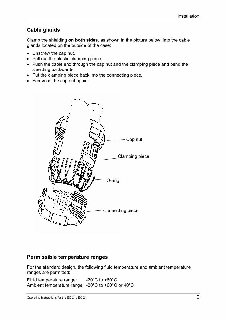
Installation
10 Operating Instructions for the EC 21 EC 24
Installing the remote totalizer
ServicemodulTERZ94trm
TERZ94p
Impulsausgaumlnge
Datenschnittstelle
Datenschnittstelle
EZDRS-485 Boot
TP-GND
Impulseingang
X2_0
X4
X15
X9X
151
X5
CX
2
CX
3
CX6
CX
1
L1
X6_0
X152
X_S1
XLP1
Ree
d 1+
3 2
+4S
enso
rver
staumlr
ker 3
+4W
iega
nd 3
+5
4+6
4
2 6
531X_S2 X10-0
TEMP_LM7X
EZSENS01
PT1000
5313
2
1
C21
C1
V12
V13
V14
C22
Q1
X7
X16_0X1X3 Taster
RESET
X_TERZ90
S3 S1 S2 S4P
+
+-
-
4
5
61
2
3
Sensor
Sensor
ZaumlhlwerkZaumlhlwerk
-
-
+
+Index InputIndex Input
-
+
Sensor
Sensor
ZaumlhlwerkZaumlhlwerk
-
-
+
+Index InputIndex Input
-
+
Herst-NrHerst-Jahr
MESSTECHNIK GMBH35510 Butzbach
Vm3
Vm h3
Pbara
TdegC Zu
IomA
ErrorTyp Mode
Trockenes Gas im Normzust101325 bar0degC = 0Weitere Daten ldquoTyp-Schildrdquo
ϕ - 0102
Non Ex
If your model is designed for remote totalizing you can install the totalizer at a distance of up to 3 m from the meter case Usually the cable has already been connected to the sensor and the totalizing unit when the device is delivered Should this not be the case you will have to connect the connecting cable to input X5 terminals S1+ and S1- of the board If you have a 2-channel meter connect the second sensor to the clamps S2+ and S2- Use only shielded cables of the type LIYCY - 2 x 075 blue (1-channel Ex) LIYCY - 2 x 2 x 075 blue (2-channel Ex or 1-channel Non-Ex) LIYCY - 3 x 2 x 075 blue (2-channel Non-Ex) Maximum cable length 3 m
In hazardous areas the temperature transmitter must not be connected via the socket on the meter case In this case it is prescribed to lay a separate cable for the temperature transmitter
In addition check the plug-in jumpers XS1 XS2 and XTERZ90 on the board (see inputs and outputs in the annex) Make your settings of XS1 and XS2 as follows jumpers 3-4
Operation
Operating Instructions for the EC 21 EC 24 11
Operation Front panel and keyboard of the EC 24
ZuVm3 OutI
mAoT
degCP
baraV
m h3ErrorTyp
VOLUME CORRECTOREC 24
IP65
Further datapress buttons
II2G EEx ib ia IIC T3T4TUumlV 02 ATEX1970
-20degC +60degC40degC Ta EG-type examination certificate
Current output 4-20mA yes no
Ser-NoYear
MESSTECHNIK GMBHGermany
0085 0032
00123456Nm3
Keyboard Designation Effect
Arrow Down
bull Moves downwards within a list Moves from the first value of the list towards the last value
Arrow Right bull Moves to the right towards another list
Moves from the first list towards the last list
+ Function
Press both buttons at the same time to initiate the following functions Hold down gt2 sec Segment test Hold down lt 2 sec The coordinate will be displayed
If the EC 21 EC 24 is operated together with the measuring element of an electronic turbine meter the EC 21 EC 24 contains the totalizing unit of the meter and the data plate of the meter is located on the left side of the front panel
Operation
12 Operating Instructions for the EC 21 EC 24
Display In normal operating mode the main totalizer is displayed If you press the external control buttons you can select the other display values After an adjustable time has elapsed the EC 21 EC 24 will return to displaying the main totalizer If the display of the EC 21 EC 24 does not show anything the device is in energy-saving mode In this mode the display is completely switched off However incoming pulses are processed and the outputs are set If you press one of the two control buttons the display value will appear again Display switched off
Pointer position 1 0 0 0 0 5 8 3 1 m3
Main totalizer V
Pointer position 2 1 0 0 0 0 m3h Flow rate V
Pointer position 3 1 0 0 0 0 0 0 0 bara
Pressure P
Pointer position 4 20 0 0 0 0 0 0 degC
Temperature T
Pointer position 5 1 --
Conversion factor C (Analysis)
Pointer position 6 16 0 0 0 0 0 0 mA
Current Io
Pointer position 7 1 --
Error ID
Pointer position 8 1 --
Mode Memory
Operation
Operating Instructions for the EC 21 EC 24 13
Programming Via the parameterization and readout software The parameters of the EC 21 EC 24 can be changed using the parameterization and readout software The official parameters are protected by a calibration switch and a password The link between the laptop computer and the corrector is established via the RS 485 interface of the EC 21 24 Via the programming module For programming the EC 21 EC 24 there are four buttons on the bottom of the display board Alternatively you can program the device using the programming module (available as an accessory) The programming module is to be connected via a pin connector (see the picture below)
P crarr
orand
Programming with the programming module is to be performed in the same way as with the internal buttons
P + -
|rarr
Operation
14 Operating Instructions for the EC 21 EC 24
The external and internal buttons correspond to each other in the following way Int button Ext button Meaning
P P Display mode Switch over to programming mode (Press the button longer than 2 seconds) Programming mode Put the decimal point at the current position
+ and In display mode Move to the right within the matrix (change of column) In programming mode - Increase the decimal by 1 - Scroll in the list (Display value is identified by ldquoLldquo)
- or
In display mode Move towards the bottom (change of line) In programming mode - Decrease the decimal by 1 - Scroll in the list (Display value is identified by ldquoLldquo)
|rarr |rarr In display mode Short-term view of the coordinate (eg A01) In programming mode Go to the right by one decimal place (if the last decimal has been reached Quit programming mode)
Operation
Operating Instructions for the EC 21 EC 24 15
Principle of programming For programming you must always proceed as follows bull First change over to the display value to be modified
minus To do this press either the control button (only forwards) minus or the internal buttons ldquo+rdquo and ldquo-rdquo or the external buttons ldquoandrdquo and ldquoorrdquo (forwards
and backwards) bull Change to programming mode by pressing ldquoPrdquo for at least 2 seconds On the left
side of the display a flashing character or cursor will appear
0 1 2 32 3 Pm3bull You can now modify the flashing decimal by pressing either ldquo+rdquo or ldquoandrdquo (+1) or ldquo-rdquo or
ldquoorrdquo (-1) Example If you press the ldquoandldquo button three times the first decimal will be increased from 0 to 3 If an ldquoLrdquo appears on the far left side of the display this value is a list With a list you can only scroll in the specified values
bull After you have completed your programming of the first decimal press ldquo|rarr rdquo once and the next character will start to flash Now proceed with your programming until you have reached the last decimal place
bull Then press ldquo|rarrrdquo once again to have the set value accepted and quit programming mode
bull Press the ldquoPldquo button to set the decimal point behind the flashing digit With totalizers modes and integers no decimal point is permitted
bull Press the control button if you have made an error or if you want to discontinue inputting data
Display values Measured values such as the flow rate frequency etc are display values and cannot be directly modified However there are many parameters which influence the formation of these measured values These parameters are described in the following section Display values include the flow rate version number year of construction serial number value of the current output in mA for example
Flashing character
Operation
16 Operating Instructions for the EC 21 EC 24
Parameters and modes of the EC 21 EC 24 The following sections describe the meaning of the individual parameters Meter factor (pulse value) With the meter factor (pulse value) the relevant flow rate at measurement conditions is calculated from the signal frequency of the sensor element in the electronic totalizing unit
sdot=
hm3600
KfQ
3
M
f Signal frequency (Hz) K Meter factor (pulsesm3) QM Flow rate at measurement conditions (m3h) The meter factor has been calibrated in the factory in such a way that working cubic metres are directly displayed Any modification of this adjustment is within the sphere of responsibility of the operating company NOTE The new value is immediately used for all calculations performed after each modification of the meter factor The uninfluenced signal frequency of the sensor element is available at the HF output The frequency range can be determined from the meter factor K and the minimum and maximum flow rates at measurement conditions of the meter in accordance with the following formulae
K3600Qf minM
min sdot= K3600Qf maxM
max sdot=
QMmin Minimum flow rate at measurement conditions QMmax Maximum flow rate at measurement conditions K Meter factor (pulse value) Example QMmin = 16 m3h QMmax = 250 m3h K = 2362 pulsesm3
Hz510Hz2362360016fmin =sdot= Hz164Hz2326
3600250fmax =sdot=
Operation
Operating Instructions for the EC 21 EC 24 17
Totalizer factor (decimal places)
You can set the totalizer factor in coordinate Z 01 There are the following setting options
Totalizer factor Multiplier for value displayed
Decimal places
001 2 01 1 1 0 10 10 0 100 100 0
Example If the factor has been set to 01 the meter reading will be displayed with one decimal If the factor has been set to 10 the value displayed will be shown without decimals and you will obtain the actual meter reading by multiplying the value displayed by 10 Output pulse value
The output pulse value indicates how many LF output pulses correspond to one cubic metre The output pulse value can be entered in coordinate Z 02 from 001 to 100 as required
Operation
18 Operating Instructions for the EC 21 EC 24
Coordinate system
Pointer position V V P T
Designation Totalizers Flow Rate Pressure Temperature Coordinate
Line A B C D
1 Volume at base conditions Qb bara degC
2 Volume at measurement conditions Qm p min t min
3 Disturbing quantity totalizer Vb
Frequency p max t max
4 Disturbing quantity totalizer Vm Qm min pb specified value tb specified value
5 Pulse scaling factor Qm max p default t default
6 Meter factor Qm max val p binary display Factor adjustment value
7 Binary value at 05 V Offset adjustment value
8 Binary value at45 V AD binary value 9 U min
10 Monthly data memory pu min 11 Monthly data memory Rise 12 Monthly data memory Factor correction value 13 Monthly data memory Offset correction value
14 23 Monthly data memory
Pointer position
C Io Error Type Mode
Designation Analysis Outputs Error ID Mode Memory Coordinate
Line E F G Z
1 Conversion factor Current Error text TerzMode 2 K coefficient Current min Software version EcMode 3 K specified value Current max Serial number Puls_X 4 Hs Current default Checksum Puls_Y
5 Rhon Current rise Ser no pressure transmitter Time
6 CO2 Current offset p min Date 7 Zb Current damping p max Modbus address
8 Z Ser no temperature transmitter ModbusRegOffset
9 Hs ref temp T min Error bit string 10 T max Wake-up pulse 11 Ser no meter 12 Meter size 13 Battery change
Operation
Operating Instructions for the EC 21 EC 24 19
Description of individual columns Column structure
Pointer position V
Coding Coordinate Line A Description of the coordinate Unit Special feature
S 1 Nm3 Main totalizer volume at base conditions m3
S 2 m3 Main totalizer volume at measurement conditions m3
S 3 VbD Disturbing quantity totalizer volume at base conditions m3
S 4 VmD Disturbing quantity totalizer volume at measurement conditions m3
The calibration switch is realized by a jumper in the (female) interface connector For opening the calibration switch just remove the jumper Then all parameters coded with ldquoSrdquo or ldquoCrdquo can be changed
Designation of columns A to O
Press the above function key and then the key once
Unit of the value displayed or programmed
Abbreviated designation of the matrix field
Field designation shown in the display of the EC 21 EC 24
Explanatory notes on a coordinate field
Designation of the column line
Coding of the matrix fields H = Header D = Display value C = Access to a data field which is protected by the user code S = Access to a data field which is protected by the calibration switch
7
3
542
1
6
Note In the software version 10 the user code is not yet implemented To change parameters with ldquoCrdquo coding it is necessary to open the calibration switch
Operation
20 Operating Instructions for the EC 21 EC 24
Totalizers
Pointer position V
Coding Coordinate Line A Description of the coordinate Unit Special feature
S 1 Nm3 Main totalizer volume at base conditions m3
S 2 m3 Main totalizer volume at measurement conditions m3
S 3 VbD Disturbing quantity totalizer volume at base conditions m3
S 4 VmD Disturbing quantity totalizer volume at measurement conditions m3
S 5 Im3 Pulse scaling factor Im3 S 6 Im3 Meter factor Im3
D 10 23 Monthly data memory 1 14 (Date Vb Vm dVb dVm P T)
Flow rate
Pointer position V Coding Coordinate
Line B Description of the coordinate Unit Special feature
D 1 N3H Flow rate at base conditions m3h
D 2 m3h Calculated flow rate at measurement conditions m3h
D 3 F Frequency (measurement) Hz S 4 Qmlt Lower fault limit m3h S 5 Qmgt Upper fault limit m3h
D 6 Qmx Maximum value of the flow rate at measurement conditions m3h
Pressure
Pointer position P
Coding Coordinate Line C Description of the coordinate Unit Special feature
D 1 bar Measured value for pressure (absolute pressure) bara
S 2 plt Lower fault limit bara S 3 pgt Upper fault limit bara S 4 pb Specified value pressure at base conditions bara C 5 p-def Default value pressure bara D 6 Dig Pressure binary display D 7 Dig Binary value at 05 V D 8 Dig Binary value at 45 V
S 9 Umi Constant pressure transmitter base calibration V
S 10 pmi Constant pressure transmitter base calibration bara
S 11 p-S Constant pressure transmitter base calibration
S 12 pA0 Correction value pressure transmitter (factor) S 13 pA1 Correction value pressure transmitter (offset)
Operation
Operating Instructions for the EC 21 EC 24 21
Temperature
Pointer position
T
Coding Coordinate Line D Description of the coordinate Unit Special feature
D 1 degC Measured temperature value degC S 2 Tlt Lower fault limit degC S 3 Tgt Upper fault limit degC
S 4 Tb Specified value temperature at base conditions degC
C 5 T-def Default value temperature degC S 6 T-F Adjustment value (factor) S 7 T-O Adjustment value (offset) D 8 Dig Binary value of AD converter
Analysis
Pointer position C
Coding Coordinate Line E Description of the coordinate Unit Special feature
D 1 C Conversion factor 1 D 2 K K coefficient 1 C 3 K-V Specified value K coefficient (if K=const) 1 C 4 Hon Superior calorific value KWhm3 C 5 rhn Rhon Kgm3 C 6 CO2 Carbon dioxide content D 7 Zb Compressibility factor at base conditions 1
D 8 Z Compressibility factor at measurement conditions 1
S 9 TB Reference temperature superior calorific value degC
Outputs
Pointer position Io
Coding Coordinate Line F Description of the coordinate Unit Special feature
D 1 mA Current out mA C 2 Ilt Value at 4 mA mA C 3 Igt Value at 20 mA mA C 4 I-def Current default mA C 5 I-F Current rise C 6 I-O Current offset C 7 I-D Current damping
Operation
22 Operating Instructions for the EC 21 EC 24
Error ID
Pointer position Error Type
Coding Coordinate Line G Description of the coordinate Unit Special feature
D 1 ERR Error text D 2 Ver Software version S 3 SNo Serial number D 4 CRC Checksum
S 5 PNo Serial number pressure transmitter
S 6 P lt Pressure range min bar S 7 P gt Pressure range max bar
S 8 TNo Serial number temperature transmitter
S 9 T lt Temperature range min degC S 10 T gt Temperature range max degC S 11 ZNo Serial number gas meter S 12 G Meter size S 13 Bat Date of next battery change
Mode Memory
Pointer position Mode Coding Coordinate
Line Z Description of the coordinate Unit Special feature
C 1 MOD TerzMode See operating modes C 2 MOD EcMode See operating modes C 3 X Puls_ X C 4 Y Puls_ Y C 5 T Time C 6 D Date C 7 Mid Modbus address C 8 Mof Modbus register offset C 9 Err Error bit string (hexadecimal) D 10 Pul Wake-up pulse
TerzMode and EcMode are 8-digit strings where each digit stands for one mode These modes are listed in the following tables
Operation
Operating Instructions for the EC 21 EC 24 23
Operating modes
0 1 2 3 4 5 6 7 8 9 0 1 2 3 4 5 6 7 8 9
Terz
Mod
e[7]
Ope
ratin
g m
ode
1 ch
anne
l
1 ch
anne
l Vm
Sto
p
1 ch
anne
l Vm
Run
2 ch
anne
ls
XY
act
(S
W) V
m S
top
2 ch
anne
ls
XY
act
(S
W) V
m R
un
2 ch
anne
ls
XY
act
(H
W) V
m S
top
2 ch
anne
ls
XY
act
(H
W) V
m R
un
2 ch
anne
ls
XY
dea
ctiv
ated
EcM
ode[
7]
Freq
uenc
y m
ode
off
pos
edg
e
neg
edg
e
Terz
Mod
e[6]
Cur
rent
out
put
off
Iout
with
out e
rror
Iout
35
mA
with
err
or
Iout
21
8 m
A w
ith e
rror
EcM
ode[
6]
Dat
a lo
gger
m
ode
Off
Vb
Vm d
Vb
dVm p
T
Terz
Mod
e[5]
Puls
e sc
alin
g fa
ctor
001
01 1 10
100
EcM
ode[
5]
Ana
lysi
s m
ode
K=c
onst
GE
RG
AG
A
Terz
Mod
e[4]
Inte
rfac
e pr
otoc
ol
off
Mod
bus
EcM
ode[
4]
Puls
e w
idth
LF
-II
08
ms
10 m
s
20 m
s
50 m
s
75 m
s
100
ms
125
ms
250
ms
Terz
Mod
e (c
oord
inat
e Z1
) Te
rzM
ode[
3]
Dis
play
cu
t-off
time
1 m
in
5 m
in
10 m
in
15 m
in
test
mod
e
EcM
ode
(coo
rdin
ate
Z2)
EcM
ode[
3]
LF
sele
ctio
n
Vm
Vb
Terz
Mod
e[2]
Puls
e w
idth
LF
out
put
125
ms
250
ms
EcM
ode[
2]
Cur
rent
se
lect
ion
off
defa
ult
Qm
Qb
tem
p
pres
sure
Terz
Mod
e[1]
Uni
ts
m3
bar
degC
cf
EcM
ode[
1]
Tem
pera
ture
m
ode
off
PT
1000
defa
ult
Terz
Mod
e[0]
Inte
rnal
cust
omer
serv
ice
clea
r Qm
max
all c
oord
on
EcM
ode[
0]
Pres
sure
m
ode
off
on
defa
ult
0 1 2 3 4 5 6 7 8 9 0 1 2 3 4 5 6 7 8 9
Operation
24 Operating Instructions for the EC 21 EC 24
Error messages In coordinate G 01 error messages are displayed as error number followed by ldquoErrrdquo The messages no 1 to 8 are fault messages In this case the main totalizers stop and the disturbing quantity totalizers start to run The messages no 9 to 16 are warnings and have no effect on the totalizers
Error no Hexadecimal Description 1 0x0001 Parameters in EEPROM are wrong (may be wrong version) 2 0x0002 EEPROM can not be written (parameters are lost) 3 0x0004 Analog digital converter for temperature measurement 4 0x0008 Analog digital converter for pressure measurement 5 0x0010 - 6 0x0020 Measured temperature outside limits 7 0x0040 Measured pressure outside limits 8 0x0080 Hardware and software configuration do not fit 9 0x0100 -
10 0x0200 - 11 0x0400 - 12 0x0800 - 13 0x1000 Current output 14 0x2000 Too many output pulses in buffer (gt500) 15 0x4000 Sensor defect (check hardware) 16 0x8000 Sensor defect (check hardware)
In the column ldquoHexadecimalrdquo the error bit strings displayed in coordinate Z 09 are listed
Operation
Operating Instructions for the EC 21 EC 24 25
Changing the batteries (EC 24) The two batteries of the EC 24 can easily be changed without opening the corrector On the left side of the casing there is a round slotted cover which can be screwed out Behind this cover there is the battery holder In hazardous areas disconnect the battery holder and change the batteries in a safe area Afterwards connect the battery holder again (see figure) and push it into the battery compartment Now screw in the cover again and the battery change is terminated In safe areas the batteries can be changed directly without disconnecting the battery holder
If you use other batteries than the replacement batteries from RMG you run the risk of the EC 24 not being approved for areas subject to explosion hazards any more In areas subject to explosion hazards you must never insert or remove the batteries Remove the battery holder from the case and change the batteries in an area without explosion hazards
redbluebluered
Annex A Equations
26 Operating Instructions for the EC 21 EC 24
Annexes A Equations used with the EC 21 temperature corrector and
the EC 24 volume corrector Symbol Unit Designation qm = m3h Flow rate at measurement conditions fv = Hz Frequency of the volume transducer KV = Pm3 Meter factor Vm = m3 Volume at measurement conditions Pv = 1 Volume pulse KZ1 = m3P Totalizer factor (for output contacts only) qb = m3h Flow rate at base conditions Vb = m3 Volume at base conditions C(pt) = 1 Conversion factor KZ2 = m3P Totalizer factor (for output contacts only) p = bara (Absolute) pressure at measurement conditions (barg kgcm2) pb = bara Pressure at base conditions (barg kgcm2) (= 101325 bar absolute) T = degC Temperature at measurement conditions TK = K Temperature at measurement conditions in Kelvin Tb = K Temperature at base conditions (= 27315 K) K = 1 K coefficient Z = 1 Compressibility factor at measurement conditions Zb = 1 Compressibility factor at base conditions Z and Zb are calculated in compliance with GERG-88 as
per G9
Annex A Equations
Operating Instructions for the EC 21 EC 24 27
Flow rate at measurement conditions
3600Kf =q
V
Vm sdot
Volume at measurement conditions
Z1V
Vm K
1KP =V sdot
K coefficient
bZ
Z =K
Conversion factor
KTp
T p =C
Kb
bt)(p sdotsdot
sdot
Flow rate at base conditions
3600CKf = q
V
Vb sdotsdot
Volume at base conditions
Z2
t)(pmb K1C V= V sdotsdot
The pressure at measurement or base conditions is processed as absolute pressure in the relevant equations In selection mode 2 of column A however transmitters with gauge-pressure or kgcm2 scaling are also permitted If these transmitters are used the pressure at base conditions must also be indicated in the appropriate unit Both the pressure at measurement conditions and the pressure at base conditions will then be converted automatically for the relevant equations
Annex B Block diagram
28 Operating Instructions for the EC 21 EC 24
B Block diagram for the EC 21 EC 24
UP
88888888
Ree
d sw
itch
or Wie
gand
sen
sor
Pres
sure
tr
ansm
itter
Onl
y EC
24
Tem
pera
ture
sen
sor
PT 1
000
Puls
e co
mpa
rison
EZD
or R
S485
Cur
rent
mod
ule
Mem
ory+
Prin
t+C
lock TE
RZ
94
Key
boar
d
RS
485
(Mod
bus)
4 to
20
mA
Faul
tH
FLF
(Vb
or V
m)
8-di
git d
ispl
ay
Bat
tery
36
V
Inpu
tsC
orre
ctio
nO
utpu
ts
Pulseinput
Serialinterface
Currentoutput
Signaloutput
Analoginput
Analoginput
Annex C Specifications
Operating Instructions for the EC 21 EC 24 29
C Specifications
Temperature ranges Type EC 21 24 II2 G EEx ib IIC T4 from -20degC to +40degC II2 G EEx ib IIC T3 from -20degC to +60degC In the case of special designs even higher or lower fluid temperatures are possible with not explosion-protected (Non-Ex) versions
Device types Reed Supply Internal battery (Ex)
or external 24 V supply via current-loop connection by means of a power supply unit of the type KFD2-STC3-Ex1 (Ex) plus battery pack
Pulse input Reed or transistor Current output Only possible via the current-loop connection Standby battery Only in conjunction with the current-loop connection Wiegand Use Direct installation onto the TERZ 91 meter instead of the
meter head Supply Internal battery (Ex)
or external 24 V supply via current-loop connection by means of a power supply unit of the type KFD2-STC3-Ex1 (Ex) plus battery pack
Pulse input Wiegand Current output Only possible via the current-loop connection Standby battery Only in conjunction with the current-loop connection
Annex C Specifications
30 Operating Instructions for the EC 21 EC 24
Inputs Volume ndash Reed
Pulse frequency 0 Hz to 20 Hz in battery-powered mode max 1 Hz due to the service life
Pulse width ge 20 ms Voltage low le 09 V high ge 22 V
ndash Wiegand Pulse frequency 0 Hz to 300 Hz in battery-powered mode Pulse width ge 5 micros Voltage min 1 V max 5 V (depends on the sensor used)
Sensor ndash S1 input (Measurement input) (For Ex connected loads see the approval certificate) Terminals X51 (+) X52 (-) Sensor type Wiegand sensor direct Length of line lt 50 cm Jumpers X_S1 3-5 and 4-6 Wiegand sensor remote totalizer Length of line lt 50m Jumpers X_S1 3-5 and 4-6 Jumpers X_TERZ90 1-2 Reed contact Jumpers X_S1 1-3 and 2-4
Sensor ndash S2 input (Reference input or startstopreset)
(For Ex connected loads see the approval certificate) Terminals X53 (+) X54 (-) Sensor type Wiegand sensor direct Length of line lt 50 cm Jumpers X_S1 3-5 and 4-6 Wiegand sensor remote totalizer Length of line lt 50m Jumpers X_S2 3-5 and 4-6 Jumpers X_TERZ90 3-4 Reed contact Jumpers X_S2 1-3 and 2-4
Annex C Specifications
Operating Instructions for the EC 21 EC 24 31
Temperature input (hardware and software option) For Ex connected loads see the approval certificate Signal Resistor (Pt1000) 4-wire Terminals X91 (+) X92 (-) Measuring range -20degC to 60degC Resolution plusmn 02 degC Pressure transmitter
For Ex connected loads see the approval certificate Signal Voltage 05 V to 45 V Resolution 16 bits Terminals Plug X16_0
Annex C Specifications
32 Operating Instructions for the EC 21 EC 24
Outputs
HF output
In the case of the explosion-protected (Ex) design the device can only be connected to a certified intrinsically safe circuit Terminals X44 (+) X43 (-)
Output Open-drain transistor TPulse 1 ms plusmn 10 Fmax 300 Hz
Ex Non-Ex Umin 20 V 20 V Umax 28 V 30 V Imax 60 mA 400 mA External inductance 1 H External capacitance 25 microF LF output
In the case of the explosion-protected (Ex) design the device can only be connected to a certified intrinsically safe circuit (For Ex connected loads see the approval certificate) Terminals X42 (+) X41 (-) Output Open-drain transistor TPulse 125 ms plusmn 10 (Fmax 4 Hz) 250 ms plusmn 10 (Fmax 2 Hz)
Ex Non-Ex Umin 20 V 20 V Umax 28 V 30 V Imax 60 mA 400 mA External inductance 1 H External capacitance 25 microF
Annex C Specifications
Operating Instructions for the EC 21 EC 24 33
Fault output
In the case of the explosion-protected (Ex) design the device can only be connected to a certified intrinsically safe circuit (For Ex connected loads see the approval certificate) Terminals X46 (+) X45 (-) Output Open-drain transistor Ex Non-Ex Umin 20 V 20 V Umax 28 V 30 V Imax 60 mA 400 mA External inductance 1 H External capacitance 25 microF
Annex C Specifications
34 Operating Instructions for the EC 21 EC 24
Vo or RS-485 data interface
In the case of the explosion-protected (Ex) design the device can only be connected to a certified intrinsically safe circuit (For Ex connected loads see the approval certificate) Vo data interface Internal connector (from Binder) Parity Even Data bits 7 Stop bit 1 Baud rate 2400 Terminals X154 (+) 4 X153 (-) 1 X151 and X152 open Umin 70 V Ui 135 V Ii 15 mA Pi 210 mW External capacitance 25 microF External inductance 1 H Isolating device KFD2-ST2-Ex1LB (from Pepperl+Fuchs) RS-485 data interface Terminals X154 (+ supply) X153 (- supply) X152 (line A) X151 (line B) Umin 70 V Ui 105 V Ii 428 mA Pi 900 mW Inner capacitance 132 microF Inner self-inductance 600 microH External capacitance 237 microF External inductance 1 H Isolating device 17-21S1-S111 EExi (from Bartec) Note If the EZD protocol or the RS-485 bus is used the device is supplied via the data interface
Annex C Specifications
Operating Instructions for the EC 21 EC 24 35
Current-loop connection
Terminals X221 (+) X222 (-) Uext (min) 12 V Uext (max) 28 V Imin 35 mA Imax 23 mA External load (max) RLmax = (Uext - 10 V) Imax (in Ω) eg Uext = 16 V rArr RLmax = (16 V - 10 V) 23 mA = 260 Ω Current output for - minimum flow rate 4 mA - maximum flow rate 20 mA - warning 35 mA - fault 23 mA Accuracy of current output Better than 1 of the upper-range value Data for use in areas subject to explosion hazards Ui = 28 V Ii = 110 mA Pi = 770 mW Ci = 22 nF Li = 110 microF Supply Battery supply 36 V lithium cell inside the device (battery pack) External 24 V supply 24 V DC external via current-loop connection plus battery pack
Annex D Examples of connection
36 Operating Instructions for the EC 21 EC 24
D Examples of connection (EC 21 and EC 24)
Battery-powered device
Isolating deviceBARTEC Type Sekopia
Hazardous area Safe Area
ConnectorLumberg Series 0332
ConnectorBinder Series 693
PC
Equipotential bonding
Isolating amplifiersKFD2-SOT-Ex2 (24 VDC)
RS 485LIYCY 2x2x05 mm blue2
Pulse outputsLIYCY 3x2x075 mm blue2
X41 2 3 4 5 6
24 VDCPE N L1
6
6
6
5
5
5
7
9
7
11
11
11
12
12
12
PE
PE
PE
8
10
8
X151 2 3 4
BAVo-
Vo+
Fault
HF
LF
Annex D Examples of connection
Operating Instructions for the EC 21 EC 24 37
Mains-powered device (Connection only via a current module with built-in back-up battery)
Isolating deviceBARTEC Type Sekopia
Hazardous area Safe area
ConnectorLumberg Series 0332
ConnectorBinder Series 693
PC
Equipotential bonding
Isolating amplifiersKFD2-SOT-Ex2 (24 VDC)
Supply unitKFD2-STC3-Ex1 (24 VDC)orKFD2-CR-Ex120300 (24 VDC)
RS 485LIYCY 2x2x05 mm blue2
Pulse outputsLIYCY 3x2x075 mm blue2
X41 2 3 4 5 6
24 VDCPE N L1
6
6
6
5
5
5
7
9
7
11
11
11
12
12
12
PE
PE
PE
8
10
8
X151 2 3 4
BAVo-
Vo+
Fault
HF
LF
Annex E Instructions for the measuring element of the turbine meter
38 Operating Instructions for the EC 21 EC 24
E Instructions for the measuring element of the turbine meter
Construction
Part Designation Material 1 Totalizing unit 2 Clamping screw Steel 3 WF01 or WF02 sensor 4 Permanent magnet Oerstit 500 5 Lubricator
(with TERZ 94 from DN 200)
6 Radial ball bearing Nirosta steel 7 Turbine wheel Delrin aluminium 8 Flow straightener Hostaform 9 O-ring 10 Sensor sleeve with sensor Nirosta steel 11 O-ring 8x25 83FKM592
1
11 2
3
10
9
8 4
7 6 5
Electronic totalizing unit or corrector
WF01WF02 sensor
Measuring element
Annex E Instructions for the measuring element of the turbine meter
Operating Instructions for the EC 21 EC 24 39
Functional description The measuring element directly measures the flow rate at measurement conditions and in the top-mounted meter head or corrector the measured values are integrated so that the result is the gas volume which flowed through the meter The gas flow drives a turbine wheel whose speed is recorded through non-contact measurement by a sensor Therefore the meter is characterized by long-term stability and low wear An aerodynamic flow straightener (8) fitted into the meter case constricts the effective cross section of the pipe to form a ring-shaped cross-sectional area and substantially eliminates turbulence The velocity of the flowing gas increases and the gas is directed to the turbine blades The turbine wheel (7) is dynamically balanced and mounted with dust-proof ball bearings (6) A permanent magnet (4) located at the end plate of the turbine shaft induces the sensor element (3) to give a voltage pulse with each rotation of the turbine wheel This pulse is further processed by the electronic system of the meter head (1) Inside the meter head or corrector the number of pulses is divided by the meter factor (number of pulses per m3) and the result is used to calculate the volume at measurement conditions In the main totalizer the sum of the volume at measurement conditions which flowed through the meter is formed and you can read the gas volume which flowed through the meter per time unit on the flow rate display At the HF output (only in the case of an electronic measuring element) the unchanged signal frequency of the sensor element is outputted whereas for the LF output this HF frequency can be reduced by two programmable scaling factors Operating conditions Permissible types of gases The standard design of the TRZ 03 ndash TE TEL turbine meters can be used for all non-aggressive gases such as
Natural gas Air Town gas Acetylene Methane Helium Ethane Carbon dioxide (dry) Propane Nitrogen Butane Hydrogen
Special designs (PTFE lining special lubrication special material etc) can be used for aggressive and humid gases such as
Ethylene Digester gas Biogas Sulphur dioxide Acid gas etc
Annex E Instructions for the measuring element of the turbine meter
40 Operating Instructions for the EC 21 EC 24
Permissible temperature ranges For the standard design the following fluid temperature and ambient temperature ranges are permitted Fluid temperature range -20degC to +60degC For the ambient temperature range see the ID plate and Annex C on page 28
Pressure loss The pressure loss is calculated using the following formula
4
2M
P DNQ
Z=p sdotρsdot∆
where ∆p is the pressure loss [mbar] ZP is the pressure loss coefficient ρ is the density [kgm3] QM is the flow rate at measurement conditions [m3h] DN is the nominal diameter of the meter [mm] The pressure loss coefficient ZP is ZP = 5040 (TERZ 94 TRZ 03-TE) ZP = 6050 (TRZ 03-TEL) This is an approximate mean value The exact value is calculated from the pressure loss which is determined on testing the volumeter Example of calculation QM = 650 m3h DN 150 ρ = 13 kgm3 [natural gas 600 mbar]
mbar55150650315040
DNQZ=p 4
2M
P 4
2
=sdotsdot=sdotρsdot∆
Therefore the pressure loss ∆p with a TERZ 94 or TRZ 03-TE turbine meter is 55 mbar in this case
Installation The gas flow must be free of shocks and pulsations as well as free of foreign particles dust and liquids Any components affecting the gas flow must absolutely be avoided directly upstream of the TERZ 94 or TRZ 03-TE turbine meter To achieve the highest possible accuracy the following inlet pipe is to be installed upstream of the meter TERZ 94 length of 2 DN with one perforated-plate straightener TRZ 03-TE length of 2 DN (specified by Technical Guideline G 13) TRZ 03-TEL no inlet pipe required
Annex E Instructions for the measuring element of the turbine meter
Operating Instructions for the EC 21 EC 24 41
In the case of the TERZ 94 you can install the meters in any position (vertical or horizontal) up to and including the nominal diameter of DN 200 From the nominal diameter of DN 250 and in the case of the TRZ 03-TE TEL only the position stated in the purchase order is possible When you install the meter please observe the direction of flow indicated on the case The meter head (1) can be turned after the clamping screw (2) has been loosened Turn the meter head by max 360deg otherwise the signal wires can become twisted and break Start-up Connecting the gas flow
Do not fill any downstream pipelines or station sections through the TERZ 94 or TRZ 03 ndash TE TEL turbine meters This may speed up the turbine wheel and lead to excessively high flow rates with resultant damage
Short-time overload operation of 20 above the maximum flow rate Qmax is permissible No damage will occur in the case of a return flow without shocks Initializing the device Set all totalizers to the meter reading of your choice (See programming) Now check the settings of the pulse width decade scalers etc In the case of models with a current output Also check the settings of the current output NOTE All parameters can only be changed if the device has been opened
Annex F Dimensions
42 Operating Instructions for the EC 21 EC 24
Annex F Dimensions
Drwg noMESSTECHNIK GMBH35510 Butzbach
140150
120 45
140
H1
80 80
volumeterPT-correctortype EVC 24
Dimensions
0581474
Pr
EC24
Flow direction from left to right
Flow direction from right to leftStandard installation
TERZ meter(flange-design)
display
Pr
display
Oslash 6 x 1
Oslash 6 x 1
pipe no 1
pipe no 2
DN H1 25 190 40 190 50 225 80 260100 265150 295200 325250 370300 385400 375500 395
Annex G Operating instructions for the installer
Operating Instructions for the EC 21 EC 24 43
Annex G Operating instructions for the installer Identification
Type EC 21 EC 24 II 2 G EEx ib IIC T4 andor T3 TUumlV 02 ATEX 1970 Temp= -20degC+40degC andor +60degC Data see EC type approval certificate Year of construction 2004 Serial number xxxx xx 0032
Manufacturer RMG Messtechnik GmbH Otto ndash Hahn ndash Straszlige 5 D-35510 Butzbach Application
The device EC 21EC 24 is equipment for hazardous area Assemblydisassembly
When assembling it is to be made sure that the degree of protection of the case is kept A direct exposure to sun must be avoided In case of disassembly the signal circuits are to be switched to zero potential and the corresponding cables are to be removed
Installation
If one or more circuits are used it is to be made sure with the cable selection that the permissible limiting values according to the EC type approval certificate are not exceeded Each Ex signal circuit is to be run in its own cable which has to be lead through the appropriate PG cable gland A fixed laying of the intrinsically safe cables is obligatory The connecting cables are to be provided with core-end sleeves
Annex G Operating instructions for the installer
44 Operating Instructions for the EC 21 EC 24
Start-up
With the start-up of this device it is to be made sure that all cables in the clamp area are correctly connected and run The case must be completely closed With the installation and start-up the standard EN60079-14 is to be observed The device may be started up only by persons after training
Settings
The basic setting of the device takes place by RMG Messtechnik Changes of the basic setting may only be carried out by persons after training andor instruction
Maintenance
The battery changes may only take place in a safe area Repairs at this device may be carried out by RMG Messtechnik only
Safety instructions
The manual must be accessible to all persons who are authorized with the operation of the device No arbitrary changes may be made at the device since otherwise the approval becomes invalid The device may be never opened by force The warning references in this manual and the generally accepted safety rules must be observed

Operation
Operating Instructions for the EC 21 EC 24 19
Description of individual columns Column structure
Pointer position V
Coding Coordinate Line A Description of the coordinate Unit Special feature
S 1 Nm3 Main totalizer volume at base conditions m3
S 2 m3 Main totalizer volume at measurement conditions m3
S 3 VbD Disturbing quantity totalizer volume at base conditions m3
S 4 VmD Disturbing quantity totalizer volume at measurement conditions m3
The calibration switch is realized by a jumper in the (female) interface connector For opening the calibration switch just remove the jumper Then all parameters coded with ldquoSrdquo or ldquoCrdquo can be changed
Designation of columns A to O
Press the above function key and then the key once
Unit of the value displayed or programmed
Abbreviated designation of the matrix field
Field designation shown in the display of the EC 21 EC 24
Explanatory notes on a coordinate field
Designation of the column line
Coding of the matrix fields H = Header D = Display value C = Access to a data field which is protected by the user code S = Access to a data field which is protected by the calibration switch
7
3
542
1
6
Note In the software version 10 the user code is not yet implemented To change parameters with ldquoCrdquo coding it is necessary to open the calibration switch
Operation
20 Operating Instructions for the EC 21 EC 24
Totalizers
Pointer position V
Coding Coordinate Line A Description of the coordinate Unit Special feature
S 1 Nm3 Main totalizer volume at base conditions m3
S 2 m3 Main totalizer volume at measurement conditions m3
S 3 VbD Disturbing quantity totalizer volume at base conditions m3
S 4 VmD Disturbing quantity totalizer volume at measurement conditions m3
S 5 Im3 Pulse scaling factor Im3 S 6 Im3 Meter factor Im3
D 10 23 Monthly data memory 1 14 (Date Vb Vm dVb dVm P T)
Flow rate
Pointer position V Coding Coordinate
Line B Description of the coordinate Unit Special feature
D 1 N3H Flow rate at base conditions m3h
D 2 m3h Calculated flow rate at measurement conditions m3h
D 3 F Frequency (measurement) Hz S 4 Qmlt Lower fault limit m3h S 5 Qmgt Upper fault limit m3h
D 6 Qmx Maximum value of the flow rate at measurement conditions m3h
Pressure
Pointer position P
Coding Coordinate Line C Description of the coordinate Unit Special feature
D 1 bar Measured value for pressure (absolute pressure) bara
S 2 plt Lower fault limit bara S 3 pgt Upper fault limit bara S 4 pb Specified value pressure at base conditions bara C 5 p-def Default value pressure bara D 6 Dig Pressure binary display D 7 Dig Binary value at 05 V D 8 Dig Binary value at 45 V
S 9 Umi Constant pressure transmitter base calibration V
S 10 pmi Constant pressure transmitter base calibration bara
S 11 p-S Constant pressure transmitter base calibration
S 12 pA0 Correction value pressure transmitter (factor) S 13 pA1 Correction value pressure transmitter (offset)
Operation
Operating Instructions for the EC 21 EC 24 21
Temperature
Pointer position
T
Coding Coordinate Line D Description of the coordinate Unit Special feature
D 1 degC Measured temperature value degC S 2 Tlt Lower fault limit degC S 3 Tgt Upper fault limit degC
S 4 Tb Specified value temperature at base conditions degC
C 5 T-def Default value temperature degC S 6 T-F Adjustment value (factor) S 7 T-O Adjustment value (offset) D 8 Dig Binary value of AD converter
Analysis
Pointer position C
Coding Coordinate Line E Description of the coordinate Unit Special feature
D 1 C Conversion factor 1 D 2 K K coefficient 1 C 3 K-V Specified value K coefficient (if K=const) 1 C 4 Hon Superior calorific value KWhm3 C 5 rhn Rhon Kgm3 C 6 CO2 Carbon dioxide content D 7 Zb Compressibility factor at base conditions 1
D 8 Z Compressibility factor at measurement conditions 1
S 9 TB Reference temperature superior calorific value degC
Outputs
Pointer position Io
Coding Coordinate Line F Description of the coordinate Unit Special feature
D 1 mA Current out mA C 2 Ilt Value at 4 mA mA C 3 Igt Value at 20 mA mA C 4 I-def Current default mA C 5 I-F Current rise C 6 I-O Current offset C 7 I-D Current damping
Operation
22 Operating Instructions for the EC 21 EC 24
Error ID
Pointer position Error Type
Coding Coordinate Line G Description of the coordinate Unit Special feature
D 1 ERR Error text D 2 Ver Software version S 3 SNo Serial number D 4 CRC Checksum
S 5 PNo Serial number pressure transmitter
S 6 P lt Pressure range min bar S 7 P gt Pressure range max bar
S 8 TNo Serial number temperature transmitter
S 9 T lt Temperature range min degC S 10 T gt Temperature range max degC S 11 ZNo Serial number gas meter S 12 G Meter size S 13 Bat Date of next battery change
Mode Memory
Pointer position Mode Coding Coordinate
Line Z Description of the coordinate Unit Special feature
C 1 MOD TerzMode See operating modes C 2 MOD EcMode See operating modes C 3 X Puls_ X C 4 Y Puls_ Y C 5 T Time C 6 D Date C 7 Mid Modbus address C 8 Mof Modbus register offset C 9 Err Error bit string (hexadecimal) D 10 Pul Wake-up pulse
TerzMode and EcMode are 8-digit strings where each digit stands for one mode These modes are listed in the following tables
Operation
Operating Instructions for the EC 21 EC 24 23
Operating modes
0 1 2 3 4 5 6 7 8 9 0 1 2 3 4 5 6 7 8 9
Terz
Mod
e[7]
Ope
ratin
g m
ode
1 ch
anne
l
1 ch
anne
l Vm
Sto
p
1 ch
anne
l Vm
Run
2 ch
anne
ls
XY
act
(S
W) V
m S
top
2 ch
anne
ls
XY
act
(S
W) V
m R
un
2 ch
anne
ls
XY
act
(H
W) V
m S
top
2 ch
anne
ls
XY
act
(H
W) V
m R
un
2 ch
anne
ls
XY
dea
ctiv
ated
EcM
ode[
7]
Freq
uenc
y m
ode
off
pos
edg
e
neg
edg
e
Terz
Mod
e[6]
Cur
rent
out
put
off
Iout
with
out e
rror
Iout
35
mA
with
err
or
Iout
21
8 m
A w
ith e
rror
EcM
ode[
6]
Dat
a lo
gger
m
ode
Off
Vb
Vm d
Vb
dVm p
T
Terz
Mod
e[5]
Puls
e sc
alin
g fa
ctor
001
01 1 10
100
EcM
ode[
5]
Ana
lysi
s m
ode
K=c
onst
GE
RG
AG
A
Terz
Mod
e[4]
Inte
rfac
e pr
otoc
ol
off
Mod
bus
EcM
ode[
4]
Puls
e w
idth
LF
-II
08
ms
10 m
s
20 m
s
50 m
s
75 m
s
100
ms
125
ms
250
ms
Terz
Mod
e (c
oord
inat
e Z1
) Te
rzM
ode[
3]
Dis
play
cu
t-off
time
1 m
in
5 m
in
10 m
in
15 m
in
test
mod
e
EcM
ode
(coo
rdin
ate
Z2)
EcM
ode[
3]
LF
sele
ctio
n
Vm
Vb
Terz
Mod
e[2]
Puls
e w
idth
LF
out
put
125
ms
250
ms
EcM
ode[
2]
Cur
rent
se
lect
ion
off
defa
ult
Qm
Qb
tem
p
pres
sure
Terz
Mod
e[1]
Uni
ts
m3
bar
degC
cf
EcM
ode[
1]
Tem
pera
ture
m
ode
off
PT
1000
defa
ult
Terz
Mod
e[0]
Inte
rnal
cust
omer
serv
ice
clea
r Qm
max
all c
oord
on
EcM
ode[
0]
Pres
sure
m
ode
off
on
defa
ult
0 1 2 3 4 5 6 7 8 9 0 1 2 3 4 5 6 7 8 9
Operation
24 Operating Instructions for the EC 21 EC 24
Error messages In coordinate G 01 error messages are displayed as error number followed by ldquoErrrdquo The messages no 1 to 8 are fault messages In this case the main totalizers stop and the disturbing quantity totalizers start to run The messages no 9 to 16 are warnings and have no effect on the totalizers
Error no Hexadecimal Description 1 0x0001 Parameters in EEPROM are wrong (may be wrong version) 2 0x0002 EEPROM can not be written (parameters are lost) 3 0x0004 Analog digital converter for temperature measurement 4 0x0008 Analog digital converter for pressure measurement 5 0x0010 - 6 0x0020 Measured temperature outside limits 7 0x0040 Measured pressure outside limits 8 0x0080 Hardware and software configuration do not fit 9 0x0100 -
10 0x0200 - 11 0x0400 - 12 0x0800 - 13 0x1000 Current output 14 0x2000 Too many output pulses in buffer (gt500) 15 0x4000 Sensor defect (check hardware) 16 0x8000 Sensor defect (check hardware)
In the column ldquoHexadecimalrdquo the error bit strings displayed in coordinate Z 09 are listed
Operation
Operating Instructions for the EC 21 EC 24 25
Changing the batteries (EC 24) The two batteries of the EC 24 can easily be changed without opening the corrector On the left side of the casing there is a round slotted cover which can be screwed out Behind this cover there is the battery holder In hazardous areas disconnect the battery holder and change the batteries in a safe area Afterwards connect the battery holder again (see figure) and push it into the battery compartment Now screw in the cover again and the battery change is terminated In safe areas the batteries can be changed directly without disconnecting the battery holder
If you use other batteries than the replacement batteries from RMG you run the risk of the EC 24 not being approved for areas subject to explosion hazards any more In areas subject to explosion hazards you must never insert or remove the batteries Remove the battery holder from the case and change the batteries in an area without explosion hazards
redbluebluered
Annex A Equations
26 Operating Instructions for the EC 21 EC 24
Annexes A Equations used with the EC 21 temperature corrector and
the EC 24 volume corrector Symbol Unit Designation qm = m3h Flow rate at measurement conditions fv = Hz Frequency of the volume transducer KV = Pm3 Meter factor Vm = m3 Volume at measurement conditions Pv = 1 Volume pulse KZ1 = m3P Totalizer factor (for output contacts only) qb = m3h Flow rate at base conditions Vb = m3 Volume at base conditions C(pt) = 1 Conversion factor KZ2 = m3P Totalizer factor (for output contacts only) p = bara (Absolute) pressure at measurement conditions (barg kgcm2) pb = bara Pressure at base conditions (barg kgcm2) (= 101325 bar absolute) T = degC Temperature at measurement conditions TK = K Temperature at measurement conditions in Kelvin Tb = K Temperature at base conditions (= 27315 K) K = 1 K coefficient Z = 1 Compressibility factor at measurement conditions Zb = 1 Compressibility factor at base conditions Z and Zb are calculated in compliance with GERG-88 as
per G9
Annex A Equations
Operating Instructions for the EC 21 EC 24 27
Flow rate at measurement conditions
3600Kf =q
V
Vm sdot
Volume at measurement conditions
Z1V
Vm K
1KP =V sdot
K coefficient
bZ
Z =K
Conversion factor
KTp
T p =C
Kb
bt)(p sdotsdot
sdot
Flow rate at base conditions
3600CKf = q
V
Vb sdotsdot
Volume at base conditions
Z2
t)(pmb K1C V= V sdotsdot
The pressure at measurement or base conditions is processed as absolute pressure in the relevant equations In selection mode 2 of column A however transmitters with gauge-pressure or kgcm2 scaling are also permitted If these transmitters are used the pressure at base conditions must also be indicated in the appropriate unit Both the pressure at measurement conditions and the pressure at base conditions will then be converted automatically for the relevant equations
Annex B Block diagram
28 Operating Instructions for the EC 21 EC 24
B Block diagram for the EC 21 EC 24
UP
88888888
Ree
d sw
itch
or Wie
gand
sen
sor
Pres
sure
tr
ansm
itter
Onl
y EC
24
Tem
pera
ture
sen
sor
PT 1
000
Puls
e co
mpa
rison
EZD
or R
S485
Cur
rent
mod
ule
Mem
ory+
Prin
t+C
lock TE
RZ
94
Key
boar
d
RS
485
(Mod
bus)
4 to
20
mA
Faul
tH
FLF
(Vb
or V
m)
8-di
git d
ispl
ay
Bat
tery
36
V
Inpu
tsC
orre
ctio
nO
utpu
ts
Pulseinput
Serialinterface
Currentoutput
Signaloutput
Analoginput
Analoginput
Annex C Specifications
Operating Instructions for the EC 21 EC 24 29
C Specifications
Temperature ranges Type EC 21 24 II2 G EEx ib IIC T4 from -20degC to +40degC II2 G EEx ib IIC T3 from -20degC to +60degC In the case of special designs even higher or lower fluid temperatures are possible with not explosion-protected (Non-Ex) versions
Device types Reed Supply Internal battery (Ex)
or external 24 V supply via current-loop connection by means of a power supply unit of the type KFD2-STC3-Ex1 (Ex) plus battery pack
Pulse input Reed or transistor Current output Only possible via the current-loop connection Standby battery Only in conjunction with the current-loop connection Wiegand Use Direct installation onto the TERZ 91 meter instead of the
meter head Supply Internal battery (Ex)
or external 24 V supply via current-loop connection by means of a power supply unit of the type KFD2-STC3-Ex1 (Ex) plus battery pack
Pulse input Wiegand Current output Only possible via the current-loop connection Standby battery Only in conjunction with the current-loop connection
Annex C Specifications
30 Operating Instructions for the EC 21 EC 24
Inputs Volume ndash Reed
Pulse frequency 0 Hz to 20 Hz in battery-powered mode max 1 Hz due to the service life
Pulse width ge 20 ms Voltage low le 09 V high ge 22 V
ndash Wiegand Pulse frequency 0 Hz to 300 Hz in battery-powered mode Pulse width ge 5 micros Voltage min 1 V max 5 V (depends on the sensor used)
Sensor ndash S1 input (Measurement input) (For Ex connected loads see the approval certificate) Terminals X51 (+) X52 (-) Sensor type Wiegand sensor direct Length of line lt 50 cm Jumpers X_S1 3-5 and 4-6 Wiegand sensor remote totalizer Length of line lt 50m Jumpers X_S1 3-5 and 4-6 Jumpers X_TERZ90 1-2 Reed contact Jumpers X_S1 1-3 and 2-4
Sensor ndash S2 input (Reference input or startstopreset)
(For Ex connected loads see the approval certificate) Terminals X53 (+) X54 (-) Sensor type Wiegand sensor direct Length of line lt 50 cm Jumpers X_S1 3-5 and 4-6 Wiegand sensor remote totalizer Length of line lt 50m Jumpers X_S2 3-5 and 4-6 Jumpers X_TERZ90 3-4 Reed contact Jumpers X_S2 1-3 and 2-4
Annex C Specifications
Operating Instructions for the EC 21 EC 24 31
Temperature input (hardware and software option) For Ex connected loads see the approval certificate Signal Resistor (Pt1000) 4-wire Terminals X91 (+) X92 (-) Measuring range -20degC to 60degC Resolution plusmn 02 degC Pressure transmitter
For Ex connected loads see the approval certificate Signal Voltage 05 V to 45 V Resolution 16 bits Terminals Plug X16_0
Annex C Specifications
32 Operating Instructions for the EC 21 EC 24
Outputs
HF output
In the case of the explosion-protected (Ex) design the device can only be connected to a certified intrinsically safe circuit Terminals X44 (+) X43 (-)
Output Open-drain transistor TPulse 1 ms plusmn 10 Fmax 300 Hz
Ex Non-Ex Umin 20 V 20 V Umax 28 V 30 V Imax 60 mA 400 mA External inductance 1 H External capacitance 25 microF LF output
In the case of the explosion-protected (Ex) design the device can only be connected to a certified intrinsically safe circuit (For Ex connected loads see the approval certificate) Terminals X42 (+) X41 (-) Output Open-drain transistor TPulse 125 ms plusmn 10 (Fmax 4 Hz) 250 ms plusmn 10 (Fmax 2 Hz)
Ex Non-Ex Umin 20 V 20 V Umax 28 V 30 V Imax 60 mA 400 mA External inductance 1 H External capacitance 25 microF
Annex C Specifications
Operating Instructions for the EC 21 EC 24 33
Fault output
In the case of the explosion-protected (Ex) design the device can only be connected to a certified intrinsically safe circuit (For Ex connected loads see the approval certificate) Terminals X46 (+) X45 (-) Output Open-drain transistor Ex Non-Ex Umin 20 V 20 V Umax 28 V 30 V Imax 60 mA 400 mA External inductance 1 H External capacitance 25 microF
Annex C Specifications
34 Operating Instructions for the EC 21 EC 24
Vo or RS-485 data interface
In the case of the explosion-protected (Ex) design the device can only be connected to a certified intrinsically safe circuit (For Ex connected loads see the approval certificate) Vo data interface Internal connector (from Binder) Parity Even Data bits 7 Stop bit 1 Baud rate 2400 Terminals X154 (+) 4 X153 (-) 1 X151 and X152 open Umin 70 V Ui 135 V Ii 15 mA Pi 210 mW External capacitance 25 microF External inductance 1 H Isolating device KFD2-ST2-Ex1LB (from Pepperl+Fuchs) RS-485 data interface Terminals X154 (+ supply) X153 (- supply) X152 (line A) X151 (line B) Umin 70 V Ui 105 V Ii 428 mA Pi 900 mW Inner capacitance 132 microF Inner self-inductance 600 microH External capacitance 237 microF External inductance 1 H Isolating device 17-21S1-S111 EExi (from Bartec) Note If the EZD protocol or the RS-485 bus is used the device is supplied via the data interface
Annex C Specifications
Operating Instructions for the EC 21 EC 24 35
Current-loop connection
Terminals X221 (+) X222 (-) Uext (min) 12 V Uext (max) 28 V Imin 35 mA Imax 23 mA External load (max) RLmax = (Uext - 10 V) Imax (in Ω) eg Uext = 16 V rArr RLmax = (16 V - 10 V) 23 mA = 260 Ω Current output for - minimum flow rate 4 mA - maximum flow rate 20 mA - warning 35 mA - fault 23 mA Accuracy of current output Better than 1 of the upper-range value Data for use in areas subject to explosion hazards Ui = 28 V Ii = 110 mA Pi = 770 mW Ci = 22 nF Li = 110 microF Supply Battery supply 36 V lithium cell inside the device (battery pack) External 24 V supply 24 V DC external via current-loop connection plus battery pack
Annex D Examples of connection
36 Operating Instructions for the EC 21 EC 24
D Examples of connection (EC 21 and EC 24)
Battery-powered device
Isolating deviceBARTEC Type Sekopia
Hazardous area Safe Area
ConnectorLumberg Series 0332
ConnectorBinder Series 693
PC
Equipotential bonding
Isolating amplifiersKFD2-SOT-Ex2 (24 VDC)
RS 485LIYCY 2x2x05 mm blue2
Pulse outputsLIYCY 3x2x075 mm blue2
X41 2 3 4 5 6
24 VDCPE N L1
6
6
6
5
5
5
7
9
7
11
11
11
12
12
12
PE
PE
PE
8
10
8
X151 2 3 4
BAVo-
Vo+
Fault
HF
LF
Annex D Examples of connection
Operating Instructions for the EC 21 EC 24 37
Mains-powered device (Connection only via a current module with built-in back-up battery)
Isolating deviceBARTEC Type Sekopia
Hazardous area Safe area
ConnectorLumberg Series 0332
ConnectorBinder Series 693
PC
Equipotential bonding
Isolating amplifiersKFD2-SOT-Ex2 (24 VDC)
Supply unitKFD2-STC3-Ex1 (24 VDC)orKFD2-CR-Ex120300 (24 VDC)
RS 485LIYCY 2x2x05 mm blue2
Pulse outputsLIYCY 3x2x075 mm blue2
X41 2 3 4 5 6
24 VDCPE N L1
6
6
6
5
5
5
7
9
7
11
11
11
12
12
12
PE
PE
PE
8
10
8
X151 2 3 4
BAVo-
Vo+
Fault
HF
LF
Annex E Instructions for the measuring element of the turbine meter
38 Operating Instructions for the EC 21 EC 24
E Instructions for the measuring element of the turbine meter
Construction
Part Designation Material 1 Totalizing unit 2 Clamping screw Steel 3 WF01 or WF02 sensor 4 Permanent magnet Oerstit 500 5 Lubricator
(with TERZ 94 from DN 200)
6 Radial ball bearing Nirosta steel 7 Turbine wheel Delrin aluminium 8 Flow straightener Hostaform 9 O-ring 10 Sensor sleeve with sensor Nirosta steel 11 O-ring 8x25 83FKM592
1
11 2
3
10
9
8 4
7 6 5
Electronic totalizing unit or corrector
WF01WF02 sensor
Measuring element
Annex E Instructions for the measuring element of the turbine meter
Operating Instructions for the EC 21 EC 24 39
Functional description The measuring element directly measures the flow rate at measurement conditions and in the top-mounted meter head or corrector the measured values are integrated so that the result is the gas volume which flowed through the meter The gas flow drives a turbine wheel whose speed is recorded through non-contact measurement by a sensor Therefore the meter is characterized by long-term stability and low wear An aerodynamic flow straightener (8) fitted into the meter case constricts the effective cross section of the pipe to form a ring-shaped cross-sectional area and substantially eliminates turbulence The velocity of the flowing gas increases and the gas is directed to the turbine blades The turbine wheel (7) is dynamically balanced and mounted with dust-proof ball bearings (6) A permanent magnet (4) located at the end plate of the turbine shaft induces the sensor element (3) to give a voltage pulse with each rotation of the turbine wheel This pulse is further processed by the electronic system of the meter head (1) Inside the meter head or corrector the number of pulses is divided by the meter factor (number of pulses per m3) and the result is used to calculate the volume at measurement conditions In the main totalizer the sum of the volume at measurement conditions which flowed through the meter is formed and you can read the gas volume which flowed through the meter per time unit on the flow rate display At the HF output (only in the case of an electronic measuring element) the unchanged signal frequency of the sensor element is outputted whereas for the LF output this HF frequency can be reduced by two programmable scaling factors Operating conditions Permissible types of gases The standard design of the TRZ 03 ndash TE TEL turbine meters can be used for all non-aggressive gases such as
Natural gas Air Town gas Acetylene Methane Helium Ethane Carbon dioxide (dry) Propane Nitrogen Butane Hydrogen
Special designs (PTFE lining special lubrication special material etc) can be used for aggressive and humid gases such as
Ethylene Digester gas Biogas Sulphur dioxide Acid gas etc
Annex E Instructions for the measuring element of the turbine meter
40 Operating Instructions for the EC 21 EC 24
Permissible temperature ranges For the standard design the following fluid temperature and ambient temperature ranges are permitted Fluid temperature range -20degC to +60degC For the ambient temperature range see the ID plate and Annex C on page 28
Pressure loss The pressure loss is calculated using the following formula
4
2M
P DNQ
Z=p sdotρsdot∆
where ∆p is the pressure loss [mbar] ZP is the pressure loss coefficient ρ is the density [kgm3] QM is the flow rate at measurement conditions [m3h] DN is the nominal diameter of the meter [mm] The pressure loss coefficient ZP is ZP = 5040 (TERZ 94 TRZ 03-TE) ZP = 6050 (TRZ 03-TEL) This is an approximate mean value The exact value is calculated from the pressure loss which is determined on testing the volumeter Example of calculation QM = 650 m3h DN 150 ρ = 13 kgm3 [natural gas 600 mbar]
mbar55150650315040
DNQZ=p 4
2M
P 4
2
=sdotsdot=sdotρsdot∆
Therefore the pressure loss ∆p with a TERZ 94 or TRZ 03-TE turbine meter is 55 mbar in this case
Installation The gas flow must be free of shocks and pulsations as well as free of foreign particles dust and liquids Any components affecting the gas flow must absolutely be avoided directly upstream of the TERZ 94 or TRZ 03-TE turbine meter To achieve the highest possible accuracy the following inlet pipe is to be installed upstream of the meter TERZ 94 length of 2 DN with one perforated-plate straightener TRZ 03-TE length of 2 DN (specified by Technical Guideline G 13) TRZ 03-TEL no inlet pipe required
Annex E Instructions for the measuring element of the turbine meter
Operating Instructions for the EC 21 EC 24 41
In the case of the TERZ 94 you can install the meters in any position (vertical or horizontal) up to and including the nominal diameter of DN 200 From the nominal diameter of DN 250 and in the case of the TRZ 03-TE TEL only the position stated in the purchase order is possible When you install the meter please observe the direction of flow indicated on the case The meter head (1) can be turned after the clamping screw (2) has been loosened Turn the meter head by max 360deg otherwise the signal wires can become twisted and break Start-up Connecting the gas flow
Do not fill any downstream pipelines or station sections through the TERZ 94 or TRZ 03 ndash TE TEL turbine meters This may speed up the turbine wheel and lead to excessively high flow rates with resultant damage
Short-time overload operation of 20 above the maximum flow rate Qmax is permissible No damage will occur in the case of a return flow without shocks Initializing the device Set all totalizers to the meter reading of your choice (See programming) Now check the settings of the pulse width decade scalers etc In the case of models with a current output Also check the settings of the current output NOTE All parameters can only be changed if the device has been opened
Annex F Dimensions
42 Operating Instructions for the EC 21 EC 24
Annex F Dimensions
Drwg noMESSTECHNIK GMBH35510 Butzbach
140150
120 45
140
H1
80 80
volumeterPT-correctortype EVC 24
Dimensions
0581474
Pr
EC24
Flow direction from left to right
Flow direction from right to leftStandard installation
TERZ meter(flange-design)
display
Pr
display
Oslash 6 x 1
Oslash 6 x 1
pipe no 1
pipe no 2
DN H1 25 190 40 190 50 225 80 260100 265150 295200 325250 370300 385400 375500 395
Annex G Operating instructions for the installer
Operating Instructions for the EC 21 EC 24 43
Annex G Operating instructions for the installer Identification
Type EC 21 EC 24 II 2 G EEx ib IIC T4 andor T3 TUumlV 02 ATEX 1970 Temp= -20degC+40degC andor +60degC Data see EC type approval certificate Year of construction 2004 Serial number xxxx xx 0032
Manufacturer RMG Messtechnik GmbH Otto ndash Hahn ndash Straszlige 5 D-35510 Butzbach Application
The device EC 21EC 24 is equipment for hazardous area Assemblydisassembly
When assembling it is to be made sure that the degree of protection of the case is kept A direct exposure to sun must be avoided In case of disassembly the signal circuits are to be switched to zero potential and the corresponding cables are to be removed
Installation
If one or more circuits are used it is to be made sure with the cable selection that the permissible limiting values according to the EC type approval certificate are not exceeded Each Ex signal circuit is to be run in its own cable which has to be lead through the appropriate PG cable gland A fixed laying of the intrinsically safe cables is obligatory The connecting cables are to be provided with core-end sleeves
Annex G Operating instructions for the installer
44 Operating Instructions for the EC 21 EC 24
Start-up
With the start-up of this device it is to be made sure that all cables in the clamp area are correctly connected and run The case must be completely closed With the installation and start-up the standard EN60079-14 is to be observed The device may be started up only by persons after training
Settings
The basic setting of the device takes place by RMG Messtechnik Changes of the basic setting may only be carried out by persons after training andor instruction
Maintenance
The battery changes may only take place in a safe area Repairs at this device may be carried out by RMG Messtechnik only
Safety instructions
The manual must be accessible to all persons who are authorized with the operation of the device No arbitrary changes may be made at the device since otherwise the approval becomes invalid The device may be never opened by force The warning references in this manual and the generally accepted safety rules must be observed
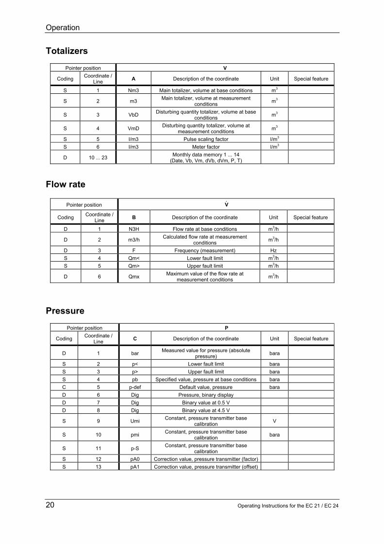
Operation
Operating Instructions for the EC 21 EC 24 25
Changing the batteries (EC 24) The two batteries of the EC 24 can easily be changed without opening the corrector On the left side of the casing there is a round slotted cover which can be screwed out Behind this cover there is the battery holder In hazardous areas disconnect the battery holder and change the batteries in a safe area Afterwards connect the battery holder again (see figure) and push it into the battery compartment Now screw in the cover again and the battery change is terminated In safe areas the batteries can be changed directly without disconnecting the battery holder
If you use other batteries than the replacement batteries from RMG you run the risk of the EC 24 not being approved for areas subject to explosion hazards any more In areas subject to explosion hazards you must never insert or remove the batteries Remove the battery holder from the case and change the batteries in an area without explosion hazards
redbluebluered
Annex A Equations
26 Operating Instructions for the EC 21 EC 24
Annexes A Equations used with the EC 21 temperature corrector and
the EC 24 volume corrector Symbol Unit Designation qm = m3h Flow rate at measurement conditions fv = Hz Frequency of the volume transducer KV = Pm3 Meter factor Vm = m3 Volume at measurement conditions Pv = 1 Volume pulse KZ1 = m3P Totalizer factor (for output contacts only) qb = m3h Flow rate at base conditions Vb = m3 Volume at base conditions C(pt) = 1 Conversion factor KZ2 = m3P Totalizer factor (for output contacts only) p = bara (Absolute) pressure at measurement conditions (barg kgcm2) pb = bara Pressure at base conditions (barg kgcm2) (= 101325 bar absolute) T = degC Temperature at measurement conditions TK = K Temperature at measurement conditions in Kelvin Tb = K Temperature at base conditions (= 27315 K) K = 1 K coefficient Z = 1 Compressibility factor at measurement conditions Zb = 1 Compressibility factor at base conditions Z and Zb are calculated in compliance with GERG-88 as
per G9
Annex A Equations
Operating Instructions for the EC 21 EC 24 27
Flow rate at measurement conditions
3600Kf =q
V
Vm sdot
Volume at measurement conditions
Z1V
Vm K
1KP =V sdot
K coefficient
bZ
Z =K
Conversion factor
KTp
T p =C
Kb
bt)(p sdotsdot
sdot
Flow rate at base conditions
3600CKf = q
V
Vb sdotsdot
Volume at base conditions
Z2
t)(pmb K1C V= V sdotsdot
The pressure at measurement or base conditions is processed as absolute pressure in the relevant equations In selection mode 2 of column A however transmitters with gauge-pressure or kgcm2 scaling are also permitted If these transmitters are used the pressure at base conditions must also be indicated in the appropriate unit Both the pressure at measurement conditions and the pressure at base conditions will then be converted automatically for the relevant equations
Annex B Block diagram
28 Operating Instructions for the EC 21 EC 24
B Block diagram for the EC 21 EC 24
UP
88888888
Ree
d sw
itch
or Wie
gand
sen
sor
Pres
sure
tr
ansm
itter
Onl
y EC
24
Tem
pera
ture
sen
sor
PT 1
000
Puls
e co
mpa
rison
EZD
or R
S485
Cur
rent
mod
ule
Mem
ory+
Prin
t+C
lock TE
RZ
94
Key
boar
d
RS
485
(Mod
bus)
4 to
20
mA
Faul
tH
FLF
(Vb
or V
m)
8-di
git d
ispl
ay
Bat
tery
36
V
Inpu
tsC
orre
ctio
nO
utpu
ts
Pulseinput
Serialinterface
Currentoutput
Signaloutput
Analoginput
Analoginput
Annex C Specifications
Operating Instructions for the EC 21 EC 24 29
C Specifications
Temperature ranges Type EC 21 24 II2 G EEx ib IIC T4 from -20degC to +40degC II2 G EEx ib IIC T3 from -20degC to +60degC In the case of special designs even higher or lower fluid temperatures are possible with not explosion-protected (Non-Ex) versions
Device types Reed Supply Internal battery (Ex)
or external 24 V supply via current-loop connection by means of a power supply unit of the type KFD2-STC3-Ex1 (Ex) plus battery pack
Pulse input Reed or transistor Current output Only possible via the current-loop connection Standby battery Only in conjunction with the current-loop connection Wiegand Use Direct installation onto the TERZ 91 meter instead of the
meter head Supply Internal battery (Ex)
or external 24 V supply via current-loop connection by means of a power supply unit of the type KFD2-STC3-Ex1 (Ex) plus battery pack
Pulse input Wiegand Current output Only possible via the current-loop connection Standby battery Only in conjunction with the current-loop connection
Annex C Specifications
30 Operating Instructions for the EC 21 EC 24
Inputs Volume ndash Reed
Pulse frequency 0 Hz to 20 Hz in battery-powered mode max 1 Hz due to the service life
Pulse width ge 20 ms Voltage low le 09 V high ge 22 V
ndash Wiegand Pulse frequency 0 Hz to 300 Hz in battery-powered mode Pulse width ge 5 micros Voltage min 1 V max 5 V (depends on the sensor used)
Sensor ndash S1 input (Measurement input) (For Ex connected loads see the approval certificate) Terminals X51 (+) X52 (-) Sensor type Wiegand sensor direct Length of line lt 50 cm Jumpers X_S1 3-5 and 4-6 Wiegand sensor remote totalizer Length of line lt 50m Jumpers X_S1 3-5 and 4-6 Jumpers X_TERZ90 1-2 Reed contact Jumpers X_S1 1-3 and 2-4
Sensor ndash S2 input (Reference input or startstopreset)
(For Ex connected loads see the approval certificate) Terminals X53 (+) X54 (-) Sensor type Wiegand sensor direct Length of line lt 50 cm Jumpers X_S1 3-5 and 4-6 Wiegand sensor remote totalizer Length of line lt 50m Jumpers X_S2 3-5 and 4-6 Jumpers X_TERZ90 3-4 Reed contact Jumpers X_S2 1-3 and 2-4
Annex C Specifications
Operating Instructions for the EC 21 EC 24 31
Temperature input (hardware and software option) For Ex connected loads see the approval certificate Signal Resistor (Pt1000) 4-wire Terminals X91 (+) X92 (-) Measuring range -20degC to 60degC Resolution plusmn 02 degC Pressure transmitter
For Ex connected loads see the approval certificate Signal Voltage 05 V to 45 V Resolution 16 bits Terminals Plug X16_0
Annex C Specifications
32 Operating Instructions for the EC 21 EC 24
Outputs
HF output
In the case of the explosion-protected (Ex) design the device can only be connected to a certified intrinsically safe circuit Terminals X44 (+) X43 (-)
Output Open-drain transistor TPulse 1 ms plusmn 10 Fmax 300 Hz
Ex Non-Ex Umin 20 V 20 V Umax 28 V 30 V Imax 60 mA 400 mA External inductance 1 H External capacitance 25 microF LF output
In the case of the explosion-protected (Ex) design the device can only be connected to a certified intrinsically safe circuit (For Ex connected loads see the approval certificate) Terminals X42 (+) X41 (-) Output Open-drain transistor TPulse 125 ms plusmn 10 (Fmax 4 Hz) 250 ms plusmn 10 (Fmax 2 Hz)
Ex Non-Ex Umin 20 V 20 V Umax 28 V 30 V Imax 60 mA 400 mA External inductance 1 H External capacitance 25 microF
Annex C Specifications
Operating Instructions for the EC 21 EC 24 33
Fault output
In the case of the explosion-protected (Ex) design the device can only be connected to a certified intrinsically safe circuit (For Ex connected loads see the approval certificate) Terminals X46 (+) X45 (-) Output Open-drain transistor Ex Non-Ex Umin 20 V 20 V Umax 28 V 30 V Imax 60 mA 400 mA External inductance 1 H External capacitance 25 microF
Annex C Specifications
34 Operating Instructions for the EC 21 EC 24
Vo or RS-485 data interface
In the case of the explosion-protected (Ex) design the device can only be connected to a certified intrinsically safe circuit (For Ex connected loads see the approval certificate) Vo data interface Internal connector (from Binder) Parity Even Data bits 7 Stop bit 1 Baud rate 2400 Terminals X154 (+) 4 X153 (-) 1 X151 and X152 open Umin 70 V Ui 135 V Ii 15 mA Pi 210 mW External capacitance 25 microF External inductance 1 H Isolating device KFD2-ST2-Ex1LB (from Pepperl+Fuchs) RS-485 data interface Terminals X154 (+ supply) X153 (- supply) X152 (line A) X151 (line B) Umin 70 V Ui 105 V Ii 428 mA Pi 900 mW Inner capacitance 132 microF Inner self-inductance 600 microH External capacitance 237 microF External inductance 1 H Isolating device 17-21S1-S111 EExi (from Bartec) Note If the EZD protocol or the RS-485 bus is used the device is supplied via the data interface
Annex C Specifications
Operating Instructions for the EC 21 EC 24 35
Current-loop connection
Terminals X221 (+) X222 (-) Uext (min) 12 V Uext (max) 28 V Imin 35 mA Imax 23 mA External load (max) RLmax = (Uext - 10 V) Imax (in Ω) eg Uext = 16 V rArr RLmax = (16 V - 10 V) 23 mA = 260 Ω Current output for - minimum flow rate 4 mA - maximum flow rate 20 mA - warning 35 mA - fault 23 mA Accuracy of current output Better than 1 of the upper-range value Data for use in areas subject to explosion hazards Ui = 28 V Ii = 110 mA Pi = 770 mW Ci = 22 nF Li = 110 microF Supply Battery supply 36 V lithium cell inside the device (battery pack) External 24 V supply 24 V DC external via current-loop connection plus battery pack
Annex D Examples of connection
36 Operating Instructions for the EC 21 EC 24
D Examples of connection (EC 21 and EC 24)
Battery-powered device
Isolating deviceBARTEC Type Sekopia
Hazardous area Safe Area
ConnectorLumberg Series 0332
ConnectorBinder Series 693
PC
Equipotential bonding
Isolating amplifiersKFD2-SOT-Ex2 (24 VDC)
RS 485LIYCY 2x2x05 mm blue2
Pulse outputsLIYCY 3x2x075 mm blue2
X41 2 3 4 5 6
24 VDCPE N L1
6
6
6
5
5
5
7
9
7
11
11
11
12
12
12
PE
PE
PE
8
10
8
X151 2 3 4
BAVo-
Vo+
Fault
HF
LF
Annex D Examples of connection
Operating Instructions for the EC 21 EC 24 37
Mains-powered device (Connection only via a current module with built-in back-up battery)
Isolating deviceBARTEC Type Sekopia
Hazardous area Safe area
ConnectorLumberg Series 0332
ConnectorBinder Series 693
PC
Equipotential bonding
Isolating amplifiersKFD2-SOT-Ex2 (24 VDC)
Supply unitKFD2-STC3-Ex1 (24 VDC)orKFD2-CR-Ex120300 (24 VDC)
RS 485LIYCY 2x2x05 mm blue2
Pulse outputsLIYCY 3x2x075 mm blue2
X41 2 3 4 5 6
24 VDCPE N L1
6
6
6
5
5
5
7
9
7
11
11
11
12
12
12
PE
PE
PE
8
10
8
X151 2 3 4
BAVo-
Vo+
Fault
HF
LF
Annex E Instructions for the measuring element of the turbine meter
38 Operating Instructions for the EC 21 EC 24
E Instructions for the measuring element of the turbine meter
Construction
Part Designation Material 1 Totalizing unit 2 Clamping screw Steel 3 WF01 or WF02 sensor 4 Permanent magnet Oerstit 500 5 Lubricator
(with TERZ 94 from DN 200)
6 Radial ball bearing Nirosta steel 7 Turbine wheel Delrin aluminium 8 Flow straightener Hostaform 9 O-ring 10 Sensor sleeve with sensor Nirosta steel 11 O-ring 8x25 83FKM592
1
11 2
3
10
9
8 4
7 6 5
Electronic totalizing unit or corrector
WF01WF02 sensor
Measuring element
Annex E Instructions for the measuring element of the turbine meter
Operating Instructions for the EC 21 EC 24 39
Functional description The measuring element directly measures the flow rate at measurement conditions and in the top-mounted meter head or corrector the measured values are integrated so that the result is the gas volume which flowed through the meter The gas flow drives a turbine wheel whose speed is recorded through non-contact measurement by a sensor Therefore the meter is characterized by long-term stability and low wear An aerodynamic flow straightener (8) fitted into the meter case constricts the effective cross section of the pipe to form a ring-shaped cross-sectional area and substantially eliminates turbulence The velocity of the flowing gas increases and the gas is directed to the turbine blades The turbine wheel (7) is dynamically balanced and mounted with dust-proof ball bearings (6) A permanent magnet (4) located at the end plate of the turbine shaft induces the sensor element (3) to give a voltage pulse with each rotation of the turbine wheel This pulse is further processed by the electronic system of the meter head (1) Inside the meter head or corrector the number of pulses is divided by the meter factor (number of pulses per m3) and the result is used to calculate the volume at measurement conditions In the main totalizer the sum of the volume at measurement conditions which flowed through the meter is formed and you can read the gas volume which flowed through the meter per time unit on the flow rate display At the HF output (only in the case of an electronic measuring element) the unchanged signal frequency of the sensor element is outputted whereas for the LF output this HF frequency can be reduced by two programmable scaling factors Operating conditions Permissible types of gases The standard design of the TRZ 03 ndash TE TEL turbine meters can be used for all non-aggressive gases such as
Natural gas Air Town gas Acetylene Methane Helium Ethane Carbon dioxide (dry) Propane Nitrogen Butane Hydrogen
Special designs (PTFE lining special lubrication special material etc) can be used for aggressive and humid gases such as
Ethylene Digester gas Biogas Sulphur dioxide Acid gas etc
Annex E Instructions for the measuring element of the turbine meter
40 Operating Instructions for the EC 21 EC 24
Permissible temperature ranges For the standard design the following fluid temperature and ambient temperature ranges are permitted Fluid temperature range -20degC to +60degC For the ambient temperature range see the ID plate and Annex C on page 28
Pressure loss The pressure loss is calculated using the following formula
4
2M
P DNQ
Z=p sdotρsdot∆
where ∆p is the pressure loss [mbar] ZP is the pressure loss coefficient ρ is the density [kgm3] QM is the flow rate at measurement conditions [m3h] DN is the nominal diameter of the meter [mm] The pressure loss coefficient ZP is ZP = 5040 (TERZ 94 TRZ 03-TE) ZP = 6050 (TRZ 03-TEL) This is an approximate mean value The exact value is calculated from the pressure loss which is determined on testing the volumeter Example of calculation QM = 650 m3h DN 150 ρ = 13 kgm3 [natural gas 600 mbar]
mbar55150650315040
DNQZ=p 4
2M
P 4
2
=sdotsdot=sdotρsdot∆
Therefore the pressure loss ∆p with a TERZ 94 or TRZ 03-TE turbine meter is 55 mbar in this case
Installation The gas flow must be free of shocks and pulsations as well as free of foreign particles dust and liquids Any components affecting the gas flow must absolutely be avoided directly upstream of the TERZ 94 or TRZ 03-TE turbine meter To achieve the highest possible accuracy the following inlet pipe is to be installed upstream of the meter TERZ 94 length of 2 DN with one perforated-plate straightener TRZ 03-TE length of 2 DN (specified by Technical Guideline G 13) TRZ 03-TEL no inlet pipe required
Annex E Instructions for the measuring element of the turbine meter
Operating Instructions for the EC 21 EC 24 41
In the case of the TERZ 94 you can install the meters in any position (vertical or horizontal) up to and including the nominal diameter of DN 200 From the nominal diameter of DN 250 and in the case of the TRZ 03-TE TEL only the position stated in the purchase order is possible When you install the meter please observe the direction of flow indicated on the case The meter head (1) can be turned after the clamping screw (2) has been loosened Turn the meter head by max 360deg otherwise the signal wires can become twisted and break Start-up Connecting the gas flow
Do not fill any downstream pipelines or station sections through the TERZ 94 or TRZ 03 ndash TE TEL turbine meters This may speed up the turbine wheel and lead to excessively high flow rates with resultant damage
Short-time overload operation of 20 above the maximum flow rate Qmax is permissible No damage will occur in the case of a return flow without shocks Initializing the device Set all totalizers to the meter reading of your choice (See programming) Now check the settings of the pulse width decade scalers etc In the case of models with a current output Also check the settings of the current output NOTE All parameters can only be changed if the device has been opened
Annex F Dimensions
42 Operating Instructions for the EC 21 EC 24
Annex F Dimensions
Drwg noMESSTECHNIK GMBH35510 Butzbach
140150
120 45
140
H1
80 80
volumeterPT-correctortype EVC 24
Dimensions
0581474
Pr
EC24
Flow direction from left to right
Flow direction from right to leftStandard installation
TERZ meter(flange-design)
display
Pr
display
Oslash 6 x 1
Oslash 6 x 1
pipe no 1
pipe no 2
DN H1 25 190 40 190 50 225 80 260100 265150 295200 325250 370300 385400 375500 395
Annex G Operating instructions for the installer
Operating Instructions for the EC 21 EC 24 43
Annex G Operating instructions for the installer Identification
Type EC 21 EC 24 II 2 G EEx ib IIC T4 andor T3 TUumlV 02 ATEX 1970 Temp= -20degC+40degC andor +60degC Data see EC type approval certificate Year of construction 2004 Serial number xxxx xx 0032
Manufacturer RMG Messtechnik GmbH Otto ndash Hahn ndash Straszlige 5 D-35510 Butzbach Application
The device EC 21EC 24 is equipment for hazardous area Assemblydisassembly
When assembling it is to be made sure that the degree of protection of the case is kept A direct exposure to sun must be avoided In case of disassembly the signal circuits are to be switched to zero potential and the corresponding cables are to be removed
Installation
If one or more circuits are used it is to be made sure with the cable selection that the permissible limiting values according to the EC type approval certificate are not exceeded Each Ex signal circuit is to be run in its own cable which has to be lead through the appropriate PG cable gland A fixed laying of the intrinsically safe cables is obligatory The connecting cables are to be provided with core-end sleeves
Annex G Operating instructions for the installer
44 Operating Instructions for the EC 21 EC 24
Start-up
With the start-up of this device it is to be made sure that all cables in the clamp area are correctly connected and run The case must be completely closed With the installation and start-up the standard EN60079-14 is to be observed The device may be started up only by persons after training
Settings
The basic setting of the device takes place by RMG Messtechnik Changes of the basic setting may only be carried out by persons after training andor instruction
Maintenance
The battery changes may only take place in a safe area Repairs at this device may be carried out by RMG Messtechnik only
Safety instructions
The manual must be accessible to all persons who are authorized with the operation of the device No arbitrary changes may be made at the device since otherwise the approval becomes invalid The device may be never opened by force The warning references in this manual and the generally accepted safety rules must be observed

Annex A Equations
Operating Instructions for the EC 21 EC 24 27
Flow rate at measurement conditions
3600Kf =q
V
Vm sdot
Volume at measurement conditions
Z1V
Vm K
1KP =V sdot
K coefficient
bZ
Z =K
Conversion factor
KTp
T p =C
Kb
bt)(p sdotsdot
sdot
Flow rate at base conditions
3600CKf = q
V
Vb sdotsdot
Volume at base conditions
Z2
t)(pmb K1C V= V sdotsdot
The pressure at measurement or base conditions is processed as absolute pressure in the relevant equations In selection mode 2 of column A however transmitters with gauge-pressure or kgcm2 scaling are also permitted If these transmitters are used the pressure at base conditions must also be indicated in the appropriate unit Both the pressure at measurement conditions and the pressure at base conditions will then be converted automatically for the relevant equations
Annex B Block diagram
28 Operating Instructions for the EC 21 EC 24
B Block diagram for the EC 21 EC 24
UP
88888888
Ree
d sw
itch
or Wie
gand
sen
sor
Pres
sure
tr
ansm
itter
Onl
y EC
24
Tem
pera
ture
sen
sor
PT 1
000
Puls
e co
mpa
rison
EZD
or R
S485
Cur
rent
mod
ule
Mem
ory+
Prin
t+C
lock TE
RZ
94
Key
boar
d
RS
485
(Mod
bus)
4 to
20
mA
Faul
tH
FLF
(Vb
or V
m)
8-di
git d
ispl
ay
Bat
tery
36
V
Inpu
tsC
orre
ctio
nO
utpu
ts
Pulseinput
Serialinterface
Currentoutput
Signaloutput
Analoginput
Analoginput
Annex C Specifications
Operating Instructions for the EC 21 EC 24 29
C Specifications
Temperature ranges Type EC 21 24 II2 G EEx ib IIC T4 from -20degC to +40degC II2 G EEx ib IIC T3 from -20degC to +60degC In the case of special designs even higher or lower fluid temperatures are possible with not explosion-protected (Non-Ex) versions
Device types Reed Supply Internal battery (Ex)
or external 24 V supply via current-loop connection by means of a power supply unit of the type KFD2-STC3-Ex1 (Ex) plus battery pack
Pulse input Reed or transistor Current output Only possible via the current-loop connection Standby battery Only in conjunction with the current-loop connection Wiegand Use Direct installation onto the TERZ 91 meter instead of the
meter head Supply Internal battery (Ex)
or external 24 V supply via current-loop connection by means of a power supply unit of the type KFD2-STC3-Ex1 (Ex) plus battery pack
Pulse input Wiegand Current output Only possible via the current-loop connection Standby battery Only in conjunction with the current-loop connection
Annex C Specifications
30 Operating Instructions for the EC 21 EC 24
Inputs Volume ndash Reed
Pulse frequency 0 Hz to 20 Hz in battery-powered mode max 1 Hz due to the service life
Pulse width ge 20 ms Voltage low le 09 V high ge 22 V
ndash Wiegand Pulse frequency 0 Hz to 300 Hz in battery-powered mode Pulse width ge 5 micros Voltage min 1 V max 5 V (depends on the sensor used)
Sensor ndash S1 input (Measurement input) (For Ex connected loads see the approval certificate) Terminals X51 (+) X52 (-) Sensor type Wiegand sensor direct Length of line lt 50 cm Jumpers X_S1 3-5 and 4-6 Wiegand sensor remote totalizer Length of line lt 50m Jumpers X_S1 3-5 and 4-6 Jumpers X_TERZ90 1-2 Reed contact Jumpers X_S1 1-3 and 2-4
Sensor ndash S2 input (Reference input or startstopreset)
(For Ex connected loads see the approval certificate) Terminals X53 (+) X54 (-) Sensor type Wiegand sensor direct Length of line lt 50 cm Jumpers X_S1 3-5 and 4-6 Wiegand sensor remote totalizer Length of line lt 50m Jumpers X_S2 3-5 and 4-6 Jumpers X_TERZ90 3-4 Reed contact Jumpers X_S2 1-3 and 2-4
Annex C Specifications
Operating Instructions for the EC 21 EC 24 31
Temperature input (hardware and software option) For Ex connected loads see the approval certificate Signal Resistor (Pt1000) 4-wire Terminals X91 (+) X92 (-) Measuring range -20degC to 60degC Resolution plusmn 02 degC Pressure transmitter
For Ex connected loads see the approval certificate Signal Voltage 05 V to 45 V Resolution 16 bits Terminals Plug X16_0
Annex C Specifications
32 Operating Instructions for the EC 21 EC 24
Outputs
HF output
In the case of the explosion-protected (Ex) design the device can only be connected to a certified intrinsically safe circuit Terminals X44 (+) X43 (-)
Output Open-drain transistor TPulse 1 ms plusmn 10 Fmax 300 Hz
Ex Non-Ex Umin 20 V 20 V Umax 28 V 30 V Imax 60 mA 400 mA External inductance 1 H External capacitance 25 microF LF output
In the case of the explosion-protected (Ex) design the device can only be connected to a certified intrinsically safe circuit (For Ex connected loads see the approval certificate) Terminals X42 (+) X41 (-) Output Open-drain transistor TPulse 125 ms plusmn 10 (Fmax 4 Hz) 250 ms plusmn 10 (Fmax 2 Hz)
Ex Non-Ex Umin 20 V 20 V Umax 28 V 30 V Imax 60 mA 400 mA External inductance 1 H External capacitance 25 microF
Annex C Specifications
Operating Instructions for the EC 21 EC 24 33
Fault output
In the case of the explosion-protected (Ex) design the device can only be connected to a certified intrinsically safe circuit (For Ex connected loads see the approval certificate) Terminals X46 (+) X45 (-) Output Open-drain transistor Ex Non-Ex Umin 20 V 20 V Umax 28 V 30 V Imax 60 mA 400 mA External inductance 1 H External capacitance 25 microF
Annex C Specifications
34 Operating Instructions for the EC 21 EC 24
Vo or RS-485 data interface
In the case of the explosion-protected (Ex) design the device can only be connected to a certified intrinsically safe circuit (For Ex connected loads see the approval certificate) Vo data interface Internal connector (from Binder) Parity Even Data bits 7 Stop bit 1 Baud rate 2400 Terminals X154 (+) 4 X153 (-) 1 X151 and X152 open Umin 70 V Ui 135 V Ii 15 mA Pi 210 mW External capacitance 25 microF External inductance 1 H Isolating device KFD2-ST2-Ex1LB (from Pepperl+Fuchs) RS-485 data interface Terminals X154 (+ supply) X153 (- supply) X152 (line A) X151 (line B) Umin 70 V Ui 105 V Ii 428 mA Pi 900 mW Inner capacitance 132 microF Inner self-inductance 600 microH External capacitance 237 microF External inductance 1 H Isolating device 17-21S1-S111 EExi (from Bartec) Note If the EZD protocol or the RS-485 bus is used the device is supplied via the data interface
Annex C Specifications
Operating Instructions for the EC 21 EC 24 35
Current-loop connection
Terminals X221 (+) X222 (-) Uext (min) 12 V Uext (max) 28 V Imin 35 mA Imax 23 mA External load (max) RLmax = (Uext - 10 V) Imax (in Ω) eg Uext = 16 V rArr RLmax = (16 V - 10 V) 23 mA = 260 Ω Current output for - minimum flow rate 4 mA - maximum flow rate 20 mA - warning 35 mA - fault 23 mA Accuracy of current output Better than 1 of the upper-range value Data for use in areas subject to explosion hazards Ui = 28 V Ii = 110 mA Pi = 770 mW Ci = 22 nF Li = 110 microF Supply Battery supply 36 V lithium cell inside the device (battery pack) External 24 V supply 24 V DC external via current-loop connection plus battery pack
Annex D Examples of connection
36 Operating Instructions for the EC 21 EC 24
D Examples of connection (EC 21 and EC 24)
Battery-powered device
Isolating deviceBARTEC Type Sekopia
Hazardous area Safe Area
ConnectorLumberg Series 0332
ConnectorBinder Series 693
PC
Equipotential bonding
Isolating amplifiersKFD2-SOT-Ex2 (24 VDC)
RS 485LIYCY 2x2x05 mm blue2
Pulse outputsLIYCY 3x2x075 mm blue2
X41 2 3 4 5 6
24 VDCPE N L1
6
6
6
5
5
5
7
9
7
11
11
11
12
12
12
PE
PE
PE
8
10
8
X151 2 3 4
BAVo-
Vo+
Fault
HF
LF
Annex D Examples of connection
Operating Instructions for the EC 21 EC 24 37
Mains-powered device (Connection only via a current module with built-in back-up battery)
Isolating deviceBARTEC Type Sekopia
Hazardous area Safe area
ConnectorLumberg Series 0332
ConnectorBinder Series 693
PC
Equipotential bonding
Isolating amplifiersKFD2-SOT-Ex2 (24 VDC)
Supply unitKFD2-STC3-Ex1 (24 VDC)orKFD2-CR-Ex120300 (24 VDC)
RS 485LIYCY 2x2x05 mm blue2
Pulse outputsLIYCY 3x2x075 mm blue2
X41 2 3 4 5 6
24 VDCPE N L1
6
6
6
5
5
5
7
9
7
11
11
11
12
12
12
PE
PE
PE
8
10
8
X151 2 3 4
BAVo-
Vo+
Fault
HF
LF
Annex E Instructions for the measuring element of the turbine meter
38 Operating Instructions for the EC 21 EC 24
E Instructions for the measuring element of the turbine meter
Construction
Part Designation Material 1 Totalizing unit 2 Clamping screw Steel 3 WF01 or WF02 sensor 4 Permanent magnet Oerstit 500 5 Lubricator
(with TERZ 94 from DN 200)
6 Radial ball bearing Nirosta steel 7 Turbine wheel Delrin aluminium 8 Flow straightener Hostaform 9 O-ring 10 Sensor sleeve with sensor Nirosta steel 11 O-ring 8x25 83FKM592
1
11 2
3
10
9
8 4
7 6 5
Electronic totalizing unit or corrector
WF01WF02 sensor
Measuring element
Annex E Instructions for the measuring element of the turbine meter
Operating Instructions for the EC 21 EC 24 39
Functional description The measuring element directly measures the flow rate at measurement conditions and in the top-mounted meter head or corrector the measured values are integrated so that the result is the gas volume which flowed through the meter The gas flow drives a turbine wheel whose speed is recorded through non-contact measurement by a sensor Therefore the meter is characterized by long-term stability and low wear An aerodynamic flow straightener (8) fitted into the meter case constricts the effective cross section of the pipe to form a ring-shaped cross-sectional area and substantially eliminates turbulence The velocity of the flowing gas increases and the gas is directed to the turbine blades The turbine wheel (7) is dynamically balanced and mounted with dust-proof ball bearings (6) A permanent magnet (4) located at the end plate of the turbine shaft induces the sensor element (3) to give a voltage pulse with each rotation of the turbine wheel This pulse is further processed by the electronic system of the meter head (1) Inside the meter head or corrector the number of pulses is divided by the meter factor (number of pulses per m3) and the result is used to calculate the volume at measurement conditions In the main totalizer the sum of the volume at measurement conditions which flowed through the meter is formed and you can read the gas volume which flowed through the meter per time unit on the flow rate display At the HF output (only in the case of an electronic measuring element) the unchanged signal frequency of the sensor element is outputted whereas for the LF output this HF frequency can be reduced by two programmable scaling factors Operating conditions Permissible types of gases The standard design of the TRZ 03 ndash TE TEL turbine meters can be used for all non-aggressive gases such as
Natural gas Air Town gas Acetylene Methane Helium Ethane Carbon dioxide (dry) Propane Nitrogen Butane Hydrogen
Special designs (PTFE lining special lubrication special material etc) can be used for aggressive and humid gases such as
Ethylene Digester gas Biogas Sulphur dioxide Acid gas etc
Annex E Instructions for the measuring element of the turbine meter
40 Operating Instructions for the EC 21 EC 24
Permissible temperature ranges For the standard design the following fluid temperature and ambient temperature ranges are permitted Fluid temperature range -20degC to +60degC For the ambient temperature range see the ID plate and Annex C on page 28
Pressure loss The pressure loss is calculated using the following formula
4
2M
P DNQ
Z=p sdotρsdot∆
where ∆p is the pressure loss [mbar] ZP is the pressure loss coefficient ρ is the density [kgm3] QM is the flow rate at measurement conditions [m3h] DN is the nominal diameter of the meter [mm] The pressure loss coefficient ZP is ZP = 5040 (TERZ 94 TRZ 03-TE) ZP = 6050 (TRZ 03-TEL) This is an approximate mean value The exact value is calculated from the pressure loss which is determined on testing the volumeter Example of calculation QM = 650 m3h DN 150 ρ = 13 kgm3 [natural gas 600 mbar]
mbar55150650315040
DNQZ=p 4
2M
P 4
2
=sdotsdot=sdotρsdot∆
Therefore the pressure loss ∆p with a TERZ 94 or TRZ 03-TE turbine meter is 55 mbar in this case
Installation The gas flow must be free of shocks and pulsations as well as free of foreign particles dust and liquids Any components affecting the gas flow must absolutely be avoided directly upstream of the TERZ 94 or TRZ 03-TE turbine meter To achieve the highest possible accuracy the following inlet pipe is to be installed upstream of the meter TERZ 94 length of 2 DN with one perforated-plate straightener TRZ 03-TE length of 2 DN (specified by Technical Guideline G 13) TRZ 03-TEL no inlet pipe required
Annex E Instructions for the measuring element of the turbine meter
Operating Instructions for the EC 21 EC 24 41
In the case of the TERZ 94 you can install the meters in any position (vertical or horizontal) up to and including the nominal diameter of DN 200 From the nominal diameter of DN 250 and in the case of the TRZ 03-TE TEL only the position stated in the purchase order is possible When you install the meter please observe the direction of flow indicated on the case The meter head (1) can be turned after the clamping screw (2) has been loosened Turn the meter head by max 360deg otherwise the signal wires can become twisted and break Start-up Connecting the gas flow
Do not fill any downstream pipelines or station sections through the TERZ 94 or TRZ 03 ndash TE TEL turbine meters This may speed up the turbine wheel and lead to excessively high flow rates with resultant damage
Short-time overload operation of 20 above the maximum flow rate Qmax is permissible No damage will occur in the case of a return flow without shocks Initializing the device Set all totalizers to the meter reading of your choice (See programming) Now check the settings of the pulse width decade scalers etc In the case of models with a current output Also check the settings of the current output NOTE All parameters can only be changed if the device has been opened
Annex F Dimensions
42 Operating Instructions for the EC 21 EC 24
Annex F Dimensions
Drwg noMESSTECHNIK GMBH35510 Butzbach
140150
120 45
140
H1
80 80
volumeterPT-correctortype EVC 24
Dimensions
0581474
Pr
EC24
Flow direction from left to right
Flow direction from right to leftStandard installation
TERZ meter(flange-design)
display
Pr
display
Oslash 6 x 1
Oslash 6 x 1
pipe no 1
pipe no 2
DN H1 25 190 40 190 50 225 80 260100 265150 295200 325250 370300 385400 375500 395
Annex G Operating instructions for the installer
Operating Instructions for the EC 21 EC 24 43
Annex G Operating instructions for the installer Identification
Type EC 21 EC 24 II 2 G EEx ib IIC T4 andor T3 TUumlV 02 ATEX 1970 Temp= -20degC+40degC andor +60degC Data see EC type approval certificate Year of construction 2004 Serial number xxxx xx 0032
Manufacturer RMG Messtechnik GmbH Otto ndash Hahn ndash Straszlige 5 D-35510 Butzbach Application
The device EC 21EC 24 is equipment for hazardous area Assemblydisassembly
When assembling it is to be made sure that the degree of protection of the case is kept A direct exposure to sun must be avoided In case of disassembly the signal circuits are to be switched to zero potential and the corresponding cables are to be removed
Installation
If one or more circuits are used it is to be made sure with the cable selection that the permissible limiting values according to the EC type approval certificate are not exceeded Each Ex signal circuit is to be run in its own cable which has to be lead through the appropriate PG cable gland A fixed laying of the intrinsically safe cables is obligatory The connecting cables are to be provided with core-end sleeves
Annex G Operating instructions for the installer
44 Operating Instructions for the EC 21 EC 24
Start-up
With the start-up of this device it is to be made sure that all cables in the clamp area are correctly connected and run The case must be completely closed With the installation and start-up the standard EN60079-14 is to be observed The device may be started up only by persons after training
Settings
The basic setting of the device takes place by RMG Messtechnik Changes of the basic setting may only be carried out by persons after training andor instruction
Maintenance
The battery changes may only take place in a safe area Repairs at this device may be carried out by RMG Messtechnik only
Safety instructions
The manual must be accessible to all persons who are authorized with the operation of the device No arbitrary changes may be made at the device since otherwise the approval becomes invalid The device may be never opened by force The warning references in this manual and the generally accepted safety rules must be observed

Annex C Specifications
Operating Instructions for the EC 21 EC 24 35
Current-loop connection
Terminals X221 (+) X222 (-) Uext (min) 12 V Uext (max) 28 V Imin 35 mA Imax 23 mA External load (max) RLmax = (Uext - 10 V) Imax (in Ω) eg Uext = 16 V rArr RLmax = (16 V - 10 V) 23 mA = 260 Ω Current output for - minimum flow rate 4 mA - maximum flow rate 20 mA - warning 35 mA - fault 23 mA Accuracy of current output Better than 1 of the upper-range value Data for use in areas subject to explosion hazards Ui = 28 V Ii = 110 mA Pi = 770 mW Ci = 22 nF Li = 110 microF Supply Battery supply 36 V lithium cell inside the device (battery pack) External 24 V supply 24 V DC external via current-loop connection plus battery pack
Annex D Examples of connection
36 Operating Instructions for the EC 21 EC 24
D Examples of connection (EC 21 and EC 24)
Battery-powered device
Isolating deviceBARTEC Type Sekopia
Hazardous area Safe Area
ConnectorLumberg Series 0332
ConnectorBinder Series 693
PC
Equipotential bonding
Isolating amplifiersKFD2-SOT-Ex2 (24 VDC)
RS 485LIYCY 2x2x05 mm blue2
Pulse outputsLIYCY 3x2x075 mm blue2
X41 2 3 4 5 6
24 VDCPE N L1
6
6
6
5
5
5
7
9
7
11
11
11
12
12
12
PE
PE
PE
8
10
8
X151 2 3 4
BAVo-
Vo+
Fault
HF
LF
Annex D Examples of connection
Operating Instructions for the EC 21 EC 24 37
Mains-powered device (Connection only via a current module with built-in back-up battery)
Isolating deviceBARTEC Type Sekopia
Hazardous area Safe area
ConnectorLumberg Series 0332
ConnectorBinder Series 693
PC
Equipotential bonding
Isolating amplifiersKFD2-SOT-Ex2 (24 VDC)
Supply unitKFD2-STC3-Ex1 (24 VDC)orKFD2-CR-Ex120300 (24 VDC)
RS 485LIYCY 2x2x05 mm blue2
Pulse outputsLIYCY 3x2x075 mm blue2
X41 2 3 4 5 6
24 VDCPE N L1
6
6
6
5
5
5
7
9
7
11
11
11
12
12
12
PE
PE
PE
8
10
8
X151 2 3 4
BAVo-
Vo+
Fault
HF
LF
Annex E Instructions for the measuring element of the turbine meter
38 Operating Instructions for the EC 21 EC 24
E Instructions for the measuring element of the turbine meter
Construction
Part Designation Material 1 Totalizing unit 2 Clamping screw Steel 3 WF01 or WF02 sensor 4 Permanent magnet Oerstit 500 5 Lubricator
(with TERZ 94 from DN 200)
6 Radial ball bearing Nirosta steel 7 Turbine wheel Delrin aluminium 8 Flow straightener Hostaform 9 O-ring 10 Sensor sleeve with sensor Nirosta steel 11 O-ring 8x25 83FKM592
1
11 2
3
10
9
8 4
7 6 5
Electronic totalizing unit or corrector
WF01WF02 sensor
Measuring element
Annex E Instructions for the measuring element of the turbine meter
Operating Instructions for the EC 21 EC 24 39
Functional description The measuring element directly measures the flow rate at measurement conditions and in the top-mounted meter head or corrector the measured values are integrated so that the result is the gas volume which flowed through the meter The gas flow drives a turbine wheel whose speed is recorded through non-contact measurement by a sensor Therefore the meter is characterized by long-term stability and low wear An aerodynamic flow straightener (8) fitted into the meter case constricts the effective cross section of the pipe to form a ring-shaped cross-sectional area and substantially eliminates turbulence The velocity of the flowing gas increases and the gas is directed to the turbine blades The turbine wheel (7) is dynamically balanced and mounted with dust-proof ball bearings (6) A permanent magnet (4) located at the end plate of the turbine shaft induces the sensor element (3) to give a voltage pulse with each rotation of the turbine wheel This pulse is further processed by the electronic system of the meter head (1) Inside the meter head or corrector the number of pulses is divided by the meter factor (number of pulses per m3) and the result is used to calculate the volume at measurement conditions In the main totalizer the sum of the volume at measurement conditions which flowed through the meter is formed and you can read the gas volume which flowed through the meter per time unit on the flow rate display At the HF output (only in the case of an electronic measuring element) the unchanged signal frequency of the sensor element is outputted whereas for the LF output this HF frequency can be reduced by two programmable scaling factors Operating conditions Permissible types of gases The standard design of the TRZ 03 ndash TE TEL turbine meters can be used for all non-aggressive gases such as
Natural gas Air Town gas Acetylene Methane Helium Ethane Carbon dioxide (dry) Propane Nitrogen Butane Hydrogen
Special designs (PTFE lining special lubrication special material etc) can be used for aggressive and humid gases such as
Ethylene Digester gas Biogas Sulphur dioxide Acid gas etc
Annex E Instructions for the measuring element of the turbine meter
40 Operating Instructions for the EC 21 EC 24
Permissible temperature ranges For the standard design the following fluid temperature and ambient temperature ranges are permitted Fluid temperature range -20degC to +60degC For the ambient temperature range see the ID plate and Annex C on page 28
Pressure loss The pressure loss is calculated using the following formula
4
2M
P DNQ
Z=p sdotρsdot∆
where ∆p is the pressure loss [mbar] ZP is the pressure loss coefficient ρ is the density [kgm3] QM is the flow rate at measurement conditions [m3h] DN is the nominal diameter of the meter [mm] The pressure loss coefficient ZP is ZP = 5040 (TERZ 94 TRZ 03-TE) ZP = 6050 (TRZ 03-TEL) This is an approximate mean value The exact value is calculated from the pressure loss which is determined on testing the volumeter Example of calculation QM = 650 m3h DN 150 ρ = 13 kgm3 [natural gas 600 mbar]
mbar55150650315040
DNQZ=p 4
2M
P 4
2
=sdotsdot=sdotρsdot∆
Therefore the pressure loss ∆p with a TERZ 94 or TRZ 03-TE turbine meter is 55 mbar in this case
Installation The gas flow must be free of shocks and pulsations as well as free of foreign particles dust and liquids Any components affecting the gas flow must absolutely be avoided directly upstream of the TERZ 94 or TRZ 03-TE turbine meter To achieve the highest possible accuracy the following inlet pipe is to be installed upstream of the meter TERZ 94 length of 2 DN with one perforated-plate straightener TRZ 03-TE length of 2 DN (specified by Technical Guideline G 13) TRZ 03-TEL no inlet pipe required
Annex E Instructions for the measuring element of the turbine meter
Operating Instructions for the EC 21 EC 24 41
In the case of the TERZ 94 you can install the meters in any position (vertical or horizontal) up to and including the nominal diameter of DN 200 From the nominal diameter of DN 250 and in the case of the TRZ 03-TE TEL only the position stated in the purchase order is possible When you install the meter please observe the direction of flow indicated on the case The meter head (1) can be turned after the clamping screw (2) has been loosened Turn the meter head by max 360deg otherwise the signal wires can become twisted and break Start-up Connecting the gas flow
Do not fill any downstream pipelines or station sections through the TERZ 94 or TRZ 03 ndash TE TEL turbine meters This may speed up the turbine wheel and lead to excessively high flow rates with resultant damage
Short-time overload operation of 20 above the maximum flow rate Qmax is permissible No damage will occur in the case of a return flow without shocks Initializing the device Set all totalizers to the meter reading of your choice (See programming) Now check the settings of the pulse width decade scalers etc In the case of models with a current output Also check the settings of the current output NOTE All parameters can only be changed if the device has been opened
Annex F Dimensions
42 Operating Instructions for the EC 21 EC 24
Annex F Dimensions
Drwg noMESSTECHNIK GMBH35510 Butzbach
140150
120 45
140
H1
80 80
volumeterPT-correctortype EVC 24
Dimensions
0581474
Pr
EC24
Flow direction from left to right
Flow direction from right to leftStandard installation
TERZ meter(flange-design)
display
Pr
display
Oslash 6 x 1
Oslash 6 x 1
pipe no 1
pipe no 2
DN H1 25 190 40 190 50 225 80 260100 265150 295200 325250 370300 385400 375500 395
Annex G Operating instructions for the installer
Operating Instructions for the EC 21 EC 24 43
Annex G Operating instructions for the installer Identification
Type EC 21 EC 24 II 2 G EEx ib IIC T4 andor T3 TUumlV 02 ATEX 1970 Temp= -20degC+40degC andor +60degC Data see EC type approval certificate Year of construction 2004 Serial number xxxx xx 0032
Manufacturer RMG Messtechnik GmbH Otto ndash Hahn ndash Straszlige 5 D-35510 Butzbach Application
The device EC 21EC 24 is equipment for hazardous area Assemblydisassembly
When assembling it is to be made sure that the degree of protection of the case is kept A direct exposure to sun must be avoided In case of disassembly the signal circuits are to be switched to zero potential and the corresponding cables are to be removed
Installation
If one or more circuits are used it is to be made sure with the cable selection that the permissible limiting values according to the EC type approval certificate are not exceeded Each Ex signal circuit is to be run in its own cable which has to be lead through the appropriate PG cable gland A fixed laying of the intrinsically safe cables is obligatory The connecting cables are to be provided with core-end sleeves
Annex G Operating instructions for the installer
44 Operating Instructions for the EC 21 EC 24
Start-up
With the start-up of this device it is to be made sure that all cables in the clamp area are correctly connected and run The case must be completely closed With the installation and start-up the standard EN60079-14 is to be observed The device may be started up only by persons after training
Settings
The basic setting of the device takes place by RMG Messtechnik Changes of the basic setting may only be carried out by persons after training andor instruction
Maintenance
The battery changes may only take place in a safe area Repairs at this device may be carried out by RMG Messtechnik only
Safety instructions
The manual must be accessible to all persons who are authorized with the operation of the device No arbitrary changes may be made at the device since otherwise the approval becomes invalid The device may be never opened by force The warning references in this manual and the generally accepted safety rules must be observed

Annex D Examples of connection
Operating Instructions for the EC 21 EC 24 37
Mains-powered device (Connection only via a current module with built-in back-up battery)
Isolating deviceBARTEC Type Sekopia
Hazardous area Safe area
ConnectorLumberg Series 0332
ConnectorBinder Series 693
PC
Equipotential bonding
Isolating amplifiersKFD2-SOT-Ex2 (24 VDC)
Supply unitKFD2-STC3-Ex1 (24 VDC)orKFD2-CR-Ex120300 (24 VDC)
RS 485LIYCY 2x2x05 mm blue2
Pulse outputsLIYCY 3x2x075 mm blue2
X41 2 3 4 5 6
24 VDCPE N L1
6
6
6
5
5
5
7
9
7
11
11
11
12
12
12
PE
PE
PE
8
10
8
X151 2 3 4
BAVo-
Vo+
Fault
HF
LF
Annex E Instructions for the measuring element of the turbine meter
38 Operating Instructions for the EC 21 EC 24
E Instructions for the measuring element of the turbine meter
Construction
Part Designation Material 1 Totalizing unit 2 Clamping screw Steel 3 WF01 or WF02 sensor 4 Permanent magnet Oerstit 500 5 Lubricator
(with TERZ 94 from DN 200)
6 Radial ball bearing Nirosta steel 7 Turbine wheel Delrin aluminium 8 Flow straightener Hostaform 9 O-ring 10 Sensor sleeve with sensor Nirosta steel 11 O-ring 8x25 83FKM592
1
11 2
3
10
9
8 4
7 6 5
Electronic totalizing unit or corrector
WF01WF02 sensor
Measuring element
Annex E Instructions for the measuring element of the turbine meter
Operating Instructions for the EC 21 EC 24 39
Functional description The measuring element directly measures the flow rate at measurement conditions and in the top-mounted meter head or corrector the measured values are integrated so that the result is the gas volume which flowed through the meter The gas flow drives a turbine wheel whose speed is recorded through non-contact measurement by a sensor Therefore the meter is characterized by long-term stability and low wear An aerodynamic flow straightener (8) fitted into the meter case constricts the effective cross section of the pipe to form a ring-shaped cross-sectional area and substantially eliminates turbulence The velocity of the flowing gas increases and the gas is directed to the turbine blades The turbine wheel (7) is dynamically balanced and mounted with dust-proof ball bearings (6) A permanent magnet (4) located at the end plate of the turbine shaft induces the sensor element (3) to give a voltage pulse with each rotation of the turbine wheel This pulse is further processed by the electronic system of the meter head (1) Inside the meter head or corrector the number of pulses is divided by the meter factor (number of pulses per m3) and the result is used to calculate the volume at measurement conditions In the main totalizer the sum of the volume at measurement conditions which flowed through the meter is formed and you can read the gas volume which flowed through the meter per time unit on the flow rate display At the HF output (only in the case of an electronic measuring element) the unchanged signal frequency of the sensor element is outputted whereas for the LF output this HF frequency can be reduced by two programmable scaling factors Operating conditions Permissible types of gases The standard design of the TRZ 03 ndash TE TEL turbine meters can be used for all non-aggressive gases such as
Natural gas Air Town gas Acetylene Methane Helium Ethane Carbon dioxide (dry) Propane Nitrogen Butane Hydrogen
Special designs (PTFE lining special lubrication special material etc) can be used for aggressive and humid gases such as
Ethylene Digester gas Biogas Sulphur dioxide Acid gas etc
Annex E Instructions for the measuring element of the turbine meter
40 Operating Instructions for the EC 21 EC 24
Permissible temperature ranges For the standard design the following fluid temperature and ambient temperature ranges are permitted Fluid temperature range -20degC to +60degC For the ambient temperature range see the ID plate and Annex C on page 28
Pressure loss The pressure loss is calculated using the following formula
4
2M
P DNQ
Z=p sdotρsdot∆
where ∆p is the pressure loss [mbar] ZP is the pressure loss coefficient ρ is the density [kgm3] QM is the flow rate at measurement conditions [m3h] DN is the nominal diameter of the meter [mm] The pressure loss coefficient ZP is ZP = 5040 (TERZ 94 TRZ 03-TE) ZP = 6050 (TRZ 03-TEL) This is an approximate mean value The exact value is calculated from the pressure loss which is determined on testing the volumeter Example of calculation QM = 650 m3h DN 150 ρ = 13 kgm3 [natural gas 600 mbar]
mbar55150650315040
DNQZ=p 4
2M
P 4
2
=sdotsdot=sdotρsdot∆
Therefore the pressure loss ∆p with a TERZ 94 or TRZ 03-TE turbine meter is 55 mbar in this case
Installation The gas flow must be free of shocks and pulsations as well as free of foreign particles dust and liquids Any components affecting the gas flow must absolutely be avoided directly upstream of the TERZ 94 or TRZ 03-TE turbine meter To achieve the highest possible accuracy the following inlet pipe is to be installed upstream of the meter TERZ 94 length of 2 DN with one perforated-plate straightener TRZ 03-TE length of 2 DN (specified by Technical Guideline G 13) TRZ 03-TEL no inlet pipe required
Annex E Instructions for the measuring element of the turbine meter
Operating Instructions for the EC 21 EC 24 41
In the case of the TERZ 94 you can install the meters in any position (vertical or horizontal) up to and including the nominal diameter of DN 200 From the nominal diameter of DN 250 and in the case of the TRZ 03-TE TEL only the position stated in the purchase order is possible When you install the meter please observe the direction of flow indicated on the case The meter head (1) can be turned after the clamping screw (2) has been loosened Turn the meter head by max 360deg otherwise the signal wires can become twisted and break Start-up Connecting the gas flow
Do not fill any downstream pipelines or station sections through the TERZ 94 or TRZ 03 ndash TE TEL turbine meters This may speed up the turbine wheel and lead to excessively high flow rates with resultant damage
Short-time overload operation of 20 above the maximum flow rate Qmax is permissible No damage will occur in the case of a return flow without shocks Initializing the device Set all totalizers to the meter reading of your choice (See programming) Now check the settings of the pulse width decade scalers etc In the case of models with a current output Also check the settings of the current output NOTE All parameters can only be changed if the device has been opened
Annex F Dimensions
42 Operating Instructions for the EC 21 EC 24
Annex F Dimensions
Drwg noMESSTECHNIK GMBH35510 Butzbach
140150
120 45
140
H1
80 80
volumeterPT-correctortype EVC 24
Dimensions
0581474
Pr
EC24
Flow direction from left to right
Flow direction from right to leftStandard installation
TERZ meter(flange-design)
display
Pr
display
Oslash 6 x 1
Oslash 6 x 1
pipe no 1
pipe no 2
DN H1 25 190 40 190 50 225 80 260100 265150 295200 325250 370300 385400 375500 395
Annex G Operating instructions for the installer
Operating Instructions for the EC 21 EC 24 43
Annex G Operating instructions for the installer Identification
Type EC 21 EC 24 II 2 G EEx ib IIC T4 andor T3 TUumlV 02 ATEX 1970 Temp= -20degC+40degC andor +60degC Data see EC type approval certificate Year of construction 2004 Serial number xxxx xx 0032
Manufacturer RMG Messtechnik GmbH Otto ndash Hahn ndash Straszlige 5 D-35510 Butzbach Application
The device EC 21EC 24 is equipment for hazardous area Assemblydisassembly
When assembling it is to be made sure that the degree of protection of the case is kept A direct exposure to sun must be avoided In case of disassembly the signal circuits are to be switched to zero potential and the corresponding cables are to be removed
Installation
If one or more circuits are used it is to be made sure with the cable selection that the permissible limiting values according to the EC type approval certificate are not exceeded Each Ex signal circuit is to be run in its own cable which has to be lead through the appropriate PG cable gland A fixed laying of the intrinsically safe cables is obligatory The connecting cables are to be provided with core-end sleeves
Annex G Operating instructions for the installer
44 Operating Instructions for the EC 21 EC 24
Start-up
With the start-up of this device it is to be made sure that all cables in the clamp area are correctly connected and run The case must be completely closed With the installation and start-up the standard EN60079-14 is to be observed The device may be started up only by persons after training
Settings
The basic setting of the device takes place by RMG Messtechnik Changes of the basic setting may only be carried out by persons after training andor instruction
Maintenance
The battery changes may only take place in a safe area Repairs at this device may be carried out by RMG Messtechnik only
Safety instructions
The manual must be accessible to all persons who are authorized with the operation of the device No arbitrary changes may be made at the device since otherwise the approval becomes invalid The device may be never opened by force The warning references in this manual and the generally accepted safety rules must be observed
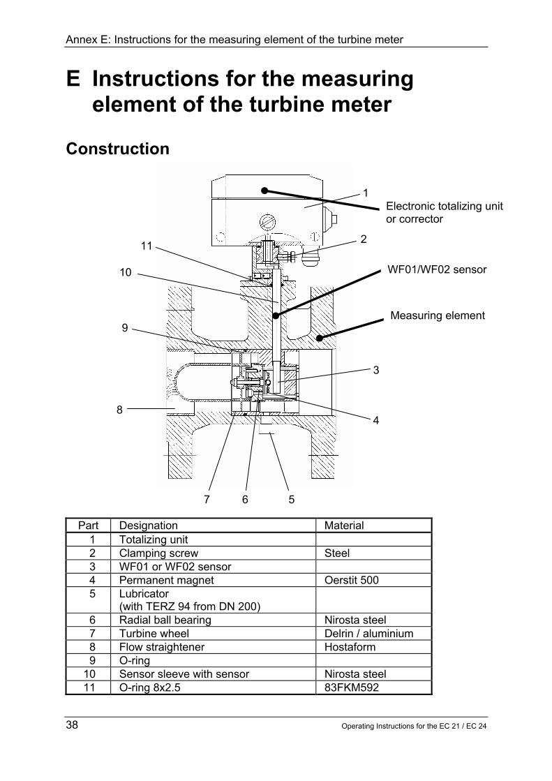
Annex E Instructions for the measuring element of the turbine meter
Operating Instructions for the EC 21 EC 24 41
In the case of the TERZ 94 you can install the meters in any position (vertical or horizontal) up to and including the nominal diameter of DN 200 From the nominal diameter of DN 250 and in the case of the TRZ 03-TE TEL only the position stated in the purchase order is possible When you install the meter please observe the direction of flow indicated on the case The meter head (1) can be turned after the clamping screw (2) has been loosened Turn the meter head by max 360deg otherwise the signal wires can become twisted and break Start-up Connecting the gas flow
Do not fill any downstream pipelines or station sections through the TERZ 94 or TRZ 03 ndash TE TEL turbine meters This may speed up the turbine wheel and lead to excessively high flow rates with resultant damage
Short-time overload operation of 20 above the maximum flow rate Qmax is permissible No damage will occur in the case of a return flow without shocks Initializing the device Set all totalizers to the meter reading of your choice (See programming) Now check the settings of the pulse width decade scalers etc In the case of models with a current output Also check the settings of the current output NOTE All parameters can only be changed if the device has been opened
Annex F Dimensions
42 Operating Instructions for the EC 21 EC 24
Annex F Dimensions
Drwg noMESSTECHNIK GMBH35510 Butzbach
140150
120 45
140
H1
80 80
volumeterPT-correctortype EVC 24
Dimensions
0581474
Pr
EC24
Flow direction from left to right
Flow direction from right to leftStandard installation
TERZ meter(flange-design)
display
Pr
display
Oslash 6 x 1
Oslash 6 x 1
pipe no 1
pipe no 2
DN H1 25 190 40 190 50 225 80 260100 265150 295200 325250 370300 385400 375500 395
Annex G Operating instructions for the installer
Operating Instructions for the EC 21 EC 24 43
Annex G Operating instructions for the installer Identification
Type EC 21 EC 24 II 2 G EEx ib IIC T4 andor T3 TUumlV 02 ATEX 1970 Temp= -20degC+40degC andor +60degC Data see EC type approval certificate Year of construction 2004 Serial number xxxx xx 0032
Manufacturer RMG Messtechnik GmbH Otto ndash Hahn ndash Straszlige 5 D-35510 Butzbach Application
The device EC 21EC 24 is equipment for hazardous area Assemblydisassembly
When assembling it is to be made sure that the degree of protection of the case is kept A direct exposure to sun must be avoided In case of disassembly the signal circuits are to be switched to zero potential and the corresponding cables are to be removed
Installation
If one or more circuits are used it is to be made sure with the cable selection that the permissible limiting values according to the EC type approval certificate are not exceeded Each Ex signal circuit is to be run in its own cable which has to be lead through the appropriate PG cable gland A fixed laying of the intrinsically safe cables is obligatory The connecting cables are to be provided with core-end sleeves
Annex G Operating instructions for the installer
44 Operating Instructions for the EC 21 EC 24
Start-up
With the start-up of this device it is to be made sure that all cables in the clamp area are correctly connected and run The case must be completely closed With the installation and start-up the standard EN60079-14 is to be observed The device may be started up only by persons after training
Settings
The basic setting of the device takes place by RMG Messtechnik Changes of the basic setting may only be carried out by persons after training andor instruction
Maintenance
The battery changes may only take place in a safe area Repairs at this device may be carried out by RMG Messtechnik only
Safety instructions
The manual must be accessible to all persons who are authorized with the operation of the device No arbitrary changes may be made at the device since otherwise the approval becomes invalid The device may be never opened by force The warning references in this manual and the generally accepted safety rules must be observed

Annex F Dimensions
42 Operating Instructions for the EC 21 EC 24
Annex F Dimensions
Drwg noMESSTECHNIK GMBH35510 Butzbach
140150
120 45
140
H1
80 80
volumeterPT-correctortype EVC 24
Dimensions
0581474
Pr
EC24
Flow direction from left to right
Flow direction from right to leftStandard installation
TERZ meter(flange-design)
display
Pr
display
Oslash 6 x 1
Oslash 6 x 1
pipe no 1
pipe no 2
DN H1 25 190 40 190 50 225 80 260100 265150 295200 325250 370300 385400 375500 395
Annex G Operating instructions for the installer
Operating Instructions for the EC 21 EC 24 43
Annex G Operating instructions for the installer Identification
Type EC 21 EC 24 II 2 G EEx ib IIC T4 andor T3 TUumlV 02 ATEX 1970 Temp= -20degC+40degC andor +60degC Data see EC type approval certificate Year of construction 2004 Serial number xxxx xx 0032
Manufacturer RMG Messtechnik GmbH Otto ndash Hahn ndash Straszlige 5 D-35510 Butzbach Application
The device EC 21EC 24 is equipment for hazardous area Assemblydisassembly
When assembling it is to be made sure that the degree of protection of the case is kept A direct exposure to sun must be avoided In case of disassembly the signal circuits are to be switched to zero potential and the corresponding cables are to be removed
Installation
If one or more circuits are used it is to be made sure with the cable selection that the permissible limiting values according to the EC type approval certificate are not exceeded Each Ex signal circuit is to be run in its own cable which has to be lead through the appropriate PG cable gland A fixed laying of the intrinsically safe cables is obligatory The connecting cables are to be provided with core-end sleeves
Annex G Operating instructions for the installer
44 Operating Instructions for the EC 21 EC 24
Start-up
With the start-up of this device it is to be made sure that all cables in the clamp area are correctly connected and run The case must be completely closed With the installation and start-up the standard EN60079-14 is to be observed The device may be started up only by persons after training
Settings
The basic setting of the device takes place by RMG Messtechnik Changes of the basic setting may only be carried out by persons after training andor instruction
Maintenance
The battery changes may only take place in a safe area Repairs at this device may be carried out by RMG Messtechnik only
Safety instructions
The manual must be accessible to all persons who are authorized with the operation of the device No arbitrary changes may be made at the device since otherwise the approval becomes invalid The device may be never opened by force The warning references in this manual and the generally accepted safety rules must be observed

Annex G Operating instructions for the installer
44 Operating Instructions for the EC 21 EC 24
Start-up
With the start-up of this device it is to be made sure that all cables in the clamp area are correctly connected and run The case must be completely closed With the installation and start-up the standard EN60079-14 is to be observed The device may be started up only by persons after training
Settings
The basic setting of the device takes place by RMG Messtechnik Changes of the basic setting may only be carried out by persons after training andor instruction
Maintenance
The battery changes may only take place in a safe area Repairs at this device may be carried out by RMG Messtechnik only
Safety instructions
The manual must be accessible to all persons who are authorized with the operation of the device No arbitrary changes may be made at the device since otherwise the approval becomes invalid The device may be never opened by force The warning references in this manual and the generally accepted safety rules must be observed