Zimmer FuZion Instruments...Use Persona Posterior Referencing Sizer to size and set rotation. Place...
44
Zimmer FuZion ™ Instruments Surgical Technique
Transcript of Zimmer FuZion Instruments...Use Persona Posterior Referencing Sizer to size and set rotation. Place...

Zimmer
FuZion™ Instruments
Surgical Technique

IntroductionSurgical goals during total knee arthroplasty (TKA) include establishment of normal leg alignment, secure implant fixation, and adequate soft tissue balancing and stability. The Zimmer FuZion Instruments are designed to help accomplish these goals by providing the surgeon with dynamic ligament feedback, as well as empirical data.
The Zimmer FuZion Instruments are based on two platforms: the Zimmer FuZion Spacer Block and Zimmer FuZion Tensor, and were specifically designed to provide crossover utility, harmonizing measured resection and gap balancing philosophies. This surgical technique describes the use of the Zimmer FuZion Instruments in common surgical workflows, used in conjunction with the Persona® Primary Instruments.
Surgical Sequence1. Resect the proximal tibia and the distal femur in
preferred order
2. Select the preferred Zimmer FuZion instrument platform
3. Use the Zimmer FuZion Instruments to establish the joint tension, while evaluating limb alignment in extension and flexion
4. Using the dynamic and empirical data provided by the Zimmer FuZion Instruments, select the optimal implant size and position.
INTRO.1
INTRO Zimmer FuZion™ Instruments Surgical Technique

TOC.1
TOC
Zimmer FuZion™ Instruments Surgical Technique
Table Of Contents
Surgical Workflow Steps 1
Surgical Technique: The Basics 5
Tensor with Zimmer FuZion Sizer 6
Spacer Block with Measured Resection 14
Spacer Block with Zimmer FuZion Sizer 22
Tensor with Gap Referencing Drill Guide 30
Transition from a CR to PS 37
Balancing Matrix 38
Persona Knee Surgical Technique Library 40
Zimmer FuZion™ Instruments Surgical Technique

SECTION
1
Every click of the tensor pinion is 1mm.
3.5mm Hex Head Screwdriver Assembly
Surgical Workflow Steps1
Surgical Workflow Steps
Fig. 11
Fig. 3 Fig. 7
Fig. 9
Fig. 13
Fig. 10
Fig. 1
3.2mm Drill Hole
Fig. 12
Tensor with Zimmer FuZion Sizer
Resect distal femur and proximal tibia. Measure extension space height & angle. Establish flexion space, size, set external rotation (drill holes for Persona Posterior Referencing 4-in-1 Cut Guide).
Place Persona Posterior Referencing 4-in-1 Cut Guide on the bone.
Double check position of the cut guide with the Zimmer FuZion 4-in-1 Adapter.
Optional: Use the shift block to adjust the Persona Posterior Referencing 4-in-1 Cut Guide, 1mm anterior or posterior, or 2° internally or externally.
Check for notching and complete femoral resections.
Verify flexion space and complete procedure.
Depress the button to adjust the rotation of the sizer body if the femur is internally or over externally rotated.
Femoral sizes are staggered on both sides of the Zimmer FuZion Sizer.
Medial Lateral Increase Femoral Rotation
Decrease Femoral Rotation

SECTION
2
1Surgical Workflow Steps
Fig. 22 Fig. 23 Fig. 24
Fig. 14
Angle is read using the angle scale and arm of proximal
attachment
Arm of proximal attachment
Fig. 16 Fig. 19
Fig. 25 Fig. 26 Fig. 27
Spacer Block with Measured Resection
Resect distal femur and proximal tibia. Measure extension space height & angle. Measure posterior condylar axis angle under tension relative to the tibia.
Use Persona Posterior Referencing Sizer to size and set rotation.
Place Persona Posterior Referencing 4-in-1 Cut Guide on the bone.
Double check position of the cut guide with the Zimmer FuZion 4-in-1 Adapter
Optional: Use the shift block to adjust the Persona Posterior Referencing 4-in-1 Cut Guide, 1mm anterior or posterior, or 2° internally or externally.
Check for notching and complete femoral resections.
Verify flexion space and complete procedure.

SECTION
3
Angle is read using the angle scale and arm of proximal
attachment
Arm of proximal attachment
Fig. 40
Fig. 30
Depress the button to adjust the rotation of the sizer body if the femur is internally or over externally rotated.
Femoral sizes are staggered on both sides of the Zimmer FuZion Sizer.
Medial Lateral Increase Femoral Rotation
Decrease Femoral Rotation
Fig. 36
Fig. 38
Fig. 42
Fig. 39
Fig. 28
3.2mm Drill Hole
Fig. 41
Spacer Block with Zimmer FuZion Sizer
Resect distal femur and proximal tibia. Measure extension space height & angle. Establish flexion space, size, set external rotation (drill holes for Persona Posterior Referencing 4-in-1 Cut Guide).
Place Persona Posterior Referencing 4-in-1 Cut Guide on the bone.
Double check position of the cut guide with the Zimmer FuZion 4-in-1 Adapter.
Optional: Use the shift block to adjust the Persona Posterior Referencing 4-in-1 Cut Guide, 1mm anterior or posterior, or 2° internally or externally.
Check for notching and complete femoral resections.
Verify flexion space and complete procedure.
Surgical Workflow Steps1

SECTION
4
3.2mm Drill Hole
Fig. 51 Fig. 51 Fig. 52
Fig. 43 Fig. 45
Stay between 3-7° of rotation.
Distance should be within 2mm of extension measurement.
Fig. 48
Fig. 53 Fig. 54 Fig. 55
Tensor with Gap Referencing Drill Guide
Resect distal femur and proximal tibia. Measure extension space height & angle. Establish flexion space and set external rotation (drill holes for Persona Posterior Referencing 4-in-1 Cut Guide )
Size the femur with the Persona Posterior Referencing Sizer. DO NOT DRILL THE HOLES!
Place Persona Posterior Referencing 4-in-1 Cut Guide on the bone.
Double check position of the cut guide with the Zimmer FuZion 4-in-1 Adapter.
Optional: Use the shift block to adjust the Persona Posterior Referencing 4-in-1 Cut Guide, 1mm anterior or posterior, or 2° internally or externally
Check for notching and complete femoral resections.
Verify flexion space and complete procedure.
Every click of the tensor pinion is 1mm.
3.5mm Hex Head Screwdriver Assembly
1Surgical Workflow Steps

SECTION
5
2
Surgical Technique: The BasicsThe clinical results of Total Knee Arthroplasty (TKA) are dependent on the surgical technique for both posterior cruciate retaining and substituting designs.
The goal of TKA is to reestablish the mechanical axis and restore stability. This is achieved by appropriate bone resection and soft tissue balance. The femoral component should be aligned with the mechanical axis. The tibia should be resected perpendicular to the mechanical axis in the coronal plane. The tibial slope is dictated by the implant design or by the natural slope of the tibia, depending on surgical philosophy.
There are three basic bone cuts in TKA: first, the proximal tibia, which influences the flexion and extension gaps; second the distal femur, which influences the extension gap; and third, the posterior femur, which influences the flexion gap. The more bone resected from the proximal tibia, the thicker the tibial component. Resected distal femoral bone will be replaced by the femoral component. Over–resection may create an extension gap that is larger than the flexion gap, resulting in instability in extension. Under-resection may create a flexion contracture. Resection of the posterior femoral condyle influences the flexion. Over resection relative to the distal femoral resection may result in a larger flexion gap resulting in flexion instability.
A fourth cut, that receives less attention, is the anterior femur, which influences the flexion gap and the patella-femoral joint. The amount of bone resected from the anterior femur is dependent on sizing and the AP position of the resection guide. Under-resection of the anterior femur may be caused by an oversized femoral component or by anterior placement of the correct component with excessive resection of the posterior condyles. This can lead to overstuffing of the patellofemoral joint with possible loss of flexion and increased tension of the anterior soft tissues. Conversely, over-resection of the anterior femur may result in notching of the distal femur. The traditional principles for ligament release state that the tight contracted concave side is released to create a rectangular gap. For a fixed varus deformity, the medial release can include the deep and superficial medial collateral ligament, the semitentinosus tendon and the pes anserenius tendons. Correction of a fixed valgus deformity, the lateral release can include the arcuate complex, iliotibial band, popliteus, and lateral collateral ligament. Following bone resection and soft tissue release the flexion and extension gaps are assessed and should be equal and symmetrical.
Surgical Technique: The Basics
Note: When assessing femoral rotation and/or tightness it is important to consider:
• Removing retractors or releasing pressure caused by retractors on the surrounding soft tissues.
• Removing the foot from the leg holder to avoid biasing the forces on the joint caused by the tibia's position relative to the femur.
• Ensuring that the flat surfaces of the cut bone are resting completely on the flat surfaces of the spacer block or tensor during assessment and there is no gapping.
• Ensuring the leg is at 90° when evaluating the flexion space.
• Everting the patella and/or a small incision window can laterally bias the flexion assessment.
• While assessing the gap, it is very important to align the spacer block's or tensor's center pivot of the femoral paddle with the center of the knee and the AP Axis of the tibial (medial 1/3 of the tibial tubercle and the anterior insertion of the posterior cruciate).
Magnet Usage:Warning: Some instruments in the Zimmer FuZion Instruments and the Persona Personalized Knee System contain magnets. All magnetic instruments should be kept a safe distance from a patient's active implantable medical device(s) (i.e. pacemaker). These types of device may be adversely affected by magnets. Instruments containing magnets should be kept on an appropriate table or stand when not in use at the surgical site.
ReferencesScuderi GR. The Basic Principles in Surgical Techniques in Total Knee Arthroplasty. Knee Arthroplasty Handbook, Springer NY. 2002; 165 - 167

SECTION
6
3Tensor with Zimmer FuZion™ Sizer
Tensor with Zimmer FuZion Sizer1. Perform Distal Femoral and Proximal Tibial
Resection (Fig. 1)• Verify that the cut surface of the tibia is perpendicular to
the long axis of the tibia and the valgus angle of the distal femoral cut restores neutral leg alignment. If desired, a drop rod can be used through the alignment hole and/or slot in the tensor.
Note: Osteophytes can impact ligament tension. Ensure all osteophytes are removed prior to assessing soft tissues.
Fig. 1

SECTION
7
Instruments
3 Tensor with Zimmer FuZion™ Sizer
2. Extension Gap Assessment and Initial Ligament Balancing
Note: Instruments are left and right specific.
• Remove all the osteophytes and complete the initial ligament balancing. Place the leg in extension. Assemble the Zimmer FuZion Tensor with the +9mm Paddle (Fig. 2). Insert the Zimmer FuZion Tensor into the extension gap.
Note: Use the +0mm Zimmer FuZion Femoral Paddle to evaluate the joint space prior to resection. Attach the +9mm Zimmer FuZion Femoral Paddle to the +0mm Zimmer FuZion Femoral Paddle (attachment is magnetic) to evaluate the joint space after the femoral condyles have been resected (Fig. 2 ).
3.5mm Hex Head Screwdriver
00-5120-087-00
Zimmer FuZion
Tensor, Femoral Assembly, Left
42-5097-021-00
3.5mm Hex Head Screwdriver Assembly
Zimmer FuZion Femoral Paddle,
+9mm 42-5097-030-09
Zimmer FuZion
Tensor, Tibial Assembly, Left
42-5097-021-01
Zimmer FuZion Femoral Paddle,
+0mm, Left42-5097-031-00
Fig. 2
Fig. 3
Scale indicates varus/valgus and femoral rotation
Alignment Rod Features
Scale indicates articular surface thickness
Every click of the tensor pinion is 1mm.
Tensor Assembly View
+9mm Zimmer FuZion Femoral
Paddle Attachment
+0mm Zimmer FuZion Femoral Paddle
• Using 3.5mm Hex Head Screwdriver, apply the appropriate amount of force to the tensor to distract the joint (Fig 3).

SECTION
8
Instruments
3Tensor with Zimmer FuZion™ Sizer
3. Flexion Gap and Setting Femoral Rotation• Remove the Zimmer FuZion Tensor from the extension
gap. Remove the +9mm Zimmer FuZion Femoral Paddle. Bring the leg into 90° of flexion. Insert the Zimmer FuZion Tensor with the +0mm Zimmer FuZion Femoral Paddle between the cut tibial surface and the uncut posterior condyles, as shown (Fig. 5).
• Using the 3.5mm Hex Head Screwdriver, apply the appropriate amount of force to distract the joint.
Note: The medial collateral ligament will engage first. The femur will then rotate internally, tightening the lateral collateral until equal tension of both is achieved.
Arm of proximal attachment
Angle is read using the angle scale and arm of proximal attachment
Fig. 5
Fig. 4
3.5mm Hex Head Screwdriver
00-5120-087-00
Zimmer FuZion
Tensor, Femoral Assembly, Left
42-5097-021-00
Zimmer FuZion
Femoral Paddle, +9mm
42-5097-030-09
Zimmer FuZion
Tensor, Tibial Assembly, Left
42-5097-021-01
Zimmer FuZion
Femoral Paddle, +0mm, Left
42-5097-031-00
Read the gap size from the engrave line on the pin
• The angle scale on the medial side of the instrument should read 0° indicating a rectangular gap. If needed, balance the extension gap using ligament release (Fig. 4).
• After the gap is balanced and rectangular, measure the gap distance using the gap scale on the anterior face of the Zimmer FuZion Tensor (Fig. 4).
• Note the extension gap measurement. It will be used to create the appropriate flexion space.
• While assessing the gap, it is very important to align the tensor's center pivot of the femoral paddle with the center of the knee and the AP Axis of the tibia (medial 1/3 of the tibial tubercle and the anterior insertion of the posterior cruciate) (Fig. 4 & Fig 5).

SECTION
9
Instruments
Depress the button to adjust the rotation of the sizer body if the femur is internally or over externally rotated.
Medial Lateral
Femoral sizes are staggered on both sides of the Zimmer FuZion Sizer.
Increase Femoral Rotation
Decrease Femoral Rotation
Note: The Zimmer FuZion Sizer can be used to adjust the amount of femoral rotation if the natural femur is internally or over externally rotated (Fig. 7). The Zimmer FuZion Sizer offers 2° increments of adjustment. Consider adjusting rotation if the scale is outside 3-7° of external rotation. Use Whiteside's line and/or the epicondylar axis as an additional visual reference to confirm component rotation. If the collateral soft-tissue does not provide adequate stability, the surgeon should use his/her professional medical judgment to assess whether a more constraining implant/system or revision implant/system is necessary.
• Assemble the Zimmer FuZion Sizer (Fig. 6).
• Attach the Zimmer FuZion Sizer to the proximal face of the Zimmer FuZion Femoral Assembly. The wide flat distal face of the Zimmer FuZion Sizer will magnetically attach to the Zimmer FuZion Tensor (Fig. 6).
Note: The Zimmer FuZion Sizer is free to slide in any direction on the proximal surface of the femoral arm.
Note: The Zimmer FuZion Sizer can be attached to the Zimmer FuZion Tensor after the tensor has been inserted in the joint.
• Slide the Zimmer FuZion Sizer up to the distal femur so that the bone side of the Zimmer FuZion Sizer is sitting parallel, or flush, with the cut distal surface.
3 Tensor with Zimmer FuZion™ Sizer
Fig. 6
Zimmer FuZion Sizer magnetically attaches and freely slides into position.
Fig. 7
1.
2.
Zimmer FuZion
Posterior Referencing Sizer Drill Guide
42-5097-061-00
Zimmer FuZion
Posterior Referencing Sizer Stylus
42-5097-060-10
Zimmer FuZion
Tensor, Femoral Assembly, Left
42-5097-021-00
Zimmer FuZion
Tensor, Tibial Assembly, Left
42-5097-021-01
Zimmer FuZion
Femoral Paddle, +0mm, Left
42-5097-031-00

SECTION
10
Instruments
3Tensor with Zimmer FuZion™ Sizer
Fig. 8
Zimmer FuZion Posterior Referencing
Sizer Stylus 42-5097-060-10
Zimmer FuZion
Tensor, Femoral Assembly, Left
42-5097-021-00
Zimmer FuZion Posterior Referencing
Sizer Drill Guide 42-5097-061-00
Zimmer FuZion
Tensor, Tibial Assembly, Left
42-5097-021-01
3.2mm Drill00-5120-085-00
Zimmer FuZion
Femoral Paddle, +0mm, Left
42-5097-031-00
• Position the tip of the Zimmer FuZion Sizer stylus onto the anterior cortex and size the femur (Fig. 8).
Caution: If a posterior rough cut is made do not use the angle and gap scales on the Zimmer FuZion Tensor.
Note: The Zimmer FuZion Sizer can only be used with the Persona Posterior Referencing 4-in-1 Cut Guides
• Use the 3.2mm Drill in the drill holes of the Zimmer FuZion Sizer to position the Persona Posterior Referencing 4-in-1 Cut Guides.
• If needed, use the +2mm/-2mm holes to adjust the flexion space as appropriate (Fig. 8).

SECTION
11
Instruments
4. Verify Rotation of Persona 4-in-1 Cut Guide and Ensure No Notching
• Insert the Persona Posterior Referencing 4-in-1 Cut Guide (Fig.9).
3 Tensor with Zimmer FuZion™ Sizer
Fig. 9
Zimmer FuZion Tensor, Femoral Assembly, Left
42-5097-021-00
Persona Posterior Referencing 4-in-1 Cut Guide - Size 7 42-5099-044-62
Zimmer FuZion
4-in-1 Cut Guide Adapter, Left
42-5097-041-00
Zimmer FuZion
Tensor, Tibial Assembly, Left
42-5097-021-01
Fig. 10
3.2mm Drill00-5120-085-00
3.5mm Hex Head Screwdriver
00-5120-087-00
• Prior to resection of the posterior condyles, attach the Zimmer FuZion 4-in-1 Cut Guide Adapter to the Zimmer FuZion Tensor and insert into the posterior holes of the Persona Posterior Referencing 4-in-1 Cut Guide (Fig. 10).
• Using the 3.5mm Hex Head Screwdriver apply the appropriate amount of force to distract the joint
• Check to ensure the posterior surface of the Persona Posterior Referencing 4-in-1 Cut Guide is parallel to the tibia and the angle read out is 0° and flexion gap is appropriate based on what was measured in extension.

SECTION
12
Instruments
3Tensor with Zimmer FuZion™ Sizer
3.2mm Drill Hole
Fig. 12
Persona Posterior Referencing 4-in-1 Cut Guide - Size 7 42-5099-044-62
Fig. 11
Persona Shift Block
3.2mm Drill00-5120-085-00
Persona Shift Block
42-5099-085-10
• If needed, use the Persona Shift Block to adjust the Persona Posterior Referencing 4-in-1 Cut Guide rotation (2°) or AP position (1mm) prior to making any cuts with the Persona Posterior Referencing 4-in-1 Cut Guide. Place the pegs of the Persona Shift Block in the holes created by the Zimmer FuZion Sizer for the Persona Posterior Referencing 4-in-1 Cut Guide. Establish the new block position by drilling through the holes on the face of the Persona Shift Block that specifies the adjustment that is intended. Use a 3.2mm Drill to drill the holes. Remove the shift block (Fig. 11). Place the Persona Posterior Referencing 4-in-1 Cut Guide on the bone. Use the Zimmer FuZion 4-in-1 Cut Guide Adapter to verify the Persona Posterior Referencing 4-in-1 Cut Guide's new position is correct.
Caution: Be sure to put the Persona Posterior Referencing 4-in-1 Cut Guide in the new holes created by the Persona Shift Block.
• Check for notching by placing a resection guide in the anterior cut slot or by using a 3.2mm Drill in the drill hole in the anterior cut slot of the Persona Posterior Referencing 4-in-1 Cut Guide before making cuts. Change size as appropriate to avoid notching (Fig. 12).
Resection Guide00-5977-084-00

SECTION
13
3 Tensor with Zimmer FuZion™ Sizer
5. Check Flexion GapNote: The +9mm Zimmer FuZion Femoral Paddle can be attached to the Zimmer FuZion +0mm Femoral Paddle and used with the Zimmer FuZion Tensor to check the flexion gap after resection (Fig. 13).
Fig. 13
Zimmer FuZion Tensor, Femoral Assembly, Left
42-5097-021-00
Zimmer FuZion
Femoral Paddle, +9mm
42-5097-030-09
Zimmer FuZion
Tensor, Tibial Assembly, Left
42-5097-021-01
Zimmer FuZion
Femoral Paddle, +0mm, Left
42-5097-031-00
6. Complete Procedure• Use Persona Primary Instruments to complete
the procedure.
Instruments

SECTION
14
Spacer Block with Measured Resection1. Perform Distal Femoral and
Proximal Tibial Resection (Fig. 14)• Verify that the cut surface of the tibia is perpendicular
to the long axis of the tibia and that the valgus angle of the distal femoral cut restores neutral leg alignment. If desired, a drop rod can be used through the alignment hold and/or slot in the spacer block.
Note: Osteophytes can impact ligament tension. Ensure all osteophytes are removed prior to assessing soft tissues.
4Spacer Block with Measured Resection
Fig. 14

SECTION
15
Instruments
Slide external dovetail (Tab A) into internal dovetail (Slot B)
1. 2.
Alignment rod features
Zimmer FuZion
Spacer Block Shim, 11mm, Left 42-5097-011-11
Zimmer FuZion
Femoral Paddle, +9mm
42-5097-030-09
Zimmer FuZion Spacer Block,
Left42-5097-011-00
Fig. 15
Zimmer FuZion
Femoral Paddle, +0mm, Left
42-5097-031-00
4 Spacer Block with Measured Resection
2. Extension Gap Assessment and Initial Ligament Balancing
Note: Instruments are left and right specific.
• Remove all the osteophytes and complete the initial ligament balancing. Place the leg in extension. Assemble the Zimmer FuZion Spacer Block (Fig. 15). Insert the Zimmer FuZion Spacer Block into the extension gap (Fig. 16).
• While assessing the gap, it is very important to align the spacer block's center pivot of the femoral paddle with the center of the knee and the AP Axis of the tibial (medial 1/3 of the tibial tubercle and the anterior insertion of the posterior cruciate) (Fig. 16).
Note: Use the +0mm Zimmer FuZion Femoral Paddle to evaluate the joint space prior to resection. Add the +9mm Zimmer FuZion Femoral Paddle to the +0mm Zimmer FuZion Femoral Paddle (attachment is magnetic) to evaluate the joint space after femoral condyles have been resected (Fig. 15).
• Zimmer FuZion Shims can be added to bottom of Zimmer FuZion Spacer Block to increase the construct thickness and achieve the proper joint tension (Fig. 15).
• Zimmer FuZion Shims are available for 11, 12, 13, 14, 16, 18, and 20mm construct thicknesses (default thickness of spacer block is 10mm) (Fig. 15).
• The angle scale is on the medial side of the instrument should read 0° indicating a rectangular gap. If needed, balance the extension gap using ligament release (Fig. 16).
• Note the Zimmer FuZion Spacer Block construct thickness. It will be used to create the appropriate flexion space.
Slot BTab A
Fig. 16
Angle is read using the angle scale and arm of proximal attachment
Arm of proximal attachment

SECTION
16
Instruments
Paddle release button in locked position
Paddle release button in unlocked position
Fig. 17
Side view: +0mm Paddle in the locked position (top)Side view: +9mm Paddle in the locked position (bottom)
Fig. 18
Side view: +0mm Paddle in the unlocked position (top)Side view: +9mm Paddle in the unlocked position (bottom)
Zimmer FuZion
Femoral Paddle, +9mm
42-5097-030-09
Zimmer FuZion
Femoral Paddle, +0mm, Left
42-5097-031-00
Zimmer FuZion
Spacer Block, Left
42-5097-011-00
4Spacer Block with Measured Resection
• The Zimmer FuZion Spacer Block can be used as a conventional solid spacer block. The femoral paddle rotation can be locked at 0°, in both +0mm and +9mm configurations, by pushing the femoral paddle towards the t-handle (Fig. 17).
• To release, simply push the button created by the femoral paddle when in the lock position until it is flush with the face of the spacer (Fig. 18).
SECTION
17
Instruments
Squeeze to Unlock
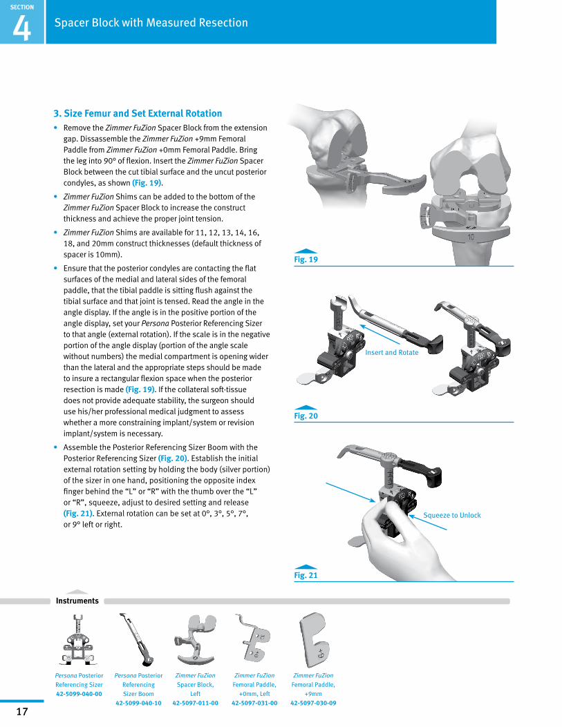
3. Size Femur and Set External Rotation• Remove the Zimmer FuZion Spacer Block from the extension
gap. Dissassemble the Zimmer FuZion +9mm Femoral Paddle from Zimmer FuZion +0mm Femoral Paddle. Bring the leg into 90° of flexion. Insert the Zimmer FuZion Spacer Block between the cut tibial surface and the uncut posterior condyles, as shown (Fig. 19).
• Zimmer FuZion Shims can be added to the bottom of the Zimmer FuZion Spacer Block to increase the construct thickness and achieve the proper joint tension.
• Zimmer FuZion Shims are available for 11, 12, 13, 14, 16, 18, and 20mm construct thicknesses (default thickness of spacer is 10mm).
• Ensure that the posterior condyles are contacting the flat surfaces of the medial and lateral sides of the femoral paddle, that the tibial paddle is sitting flush against the tibial surface and that joint is tensed. Read the angle in the angle display. If the angle is in the positive portion of the angle display, set your Persona Posterior Referencing Sizer to that angle (external rotation). If the scale is in the negative portion of the angle display (portion of the angle scale without numbers) the medial compartment is opening wider than the lateral and the appropriate steps should be made to insure a rectangular flexion space when the posterior resection is made (Fig. 19). If the collateral soft-tissue does not provide adequate stability, the surgeon should use his/her professional medical judgment to assess whether a more constraining implant/system or revision implant/system is necessary.
• Assemble the Posterior Referencing Sizer Boom with the Posterior Referencing Sizer (Fig. 20). Establish the initial external rotation setting by holding the body (silver portion) of the sizer in one hand, positioning the opposite index finger behind the “L” or “R” with the thumb over the “L” or “R”, squeeze, adjust to desired setting and release (Fig. 21). External rotation can be set at 0°, 3°, 5°, 7°, or 9° left or right.
4 Spacer Block with Measured Resection
Persona Posterior Referencing Sizer Boom
42-5099-040-10
Persona Posterior Referencing Sizer42-5099-040-00
Fig. 21
Fig. 20
Fig. 19
Zimmer FuZion
Femoral Paddle, +9mm
42-5097-030-09
Zimmer FuZion Femoral Paddle,
+0mm, Left42-5097-031-00
Zimmer FuZion Spacer Block,
Left42-5097-011-00
Insert and Rotate
SECTION
18
Instruments
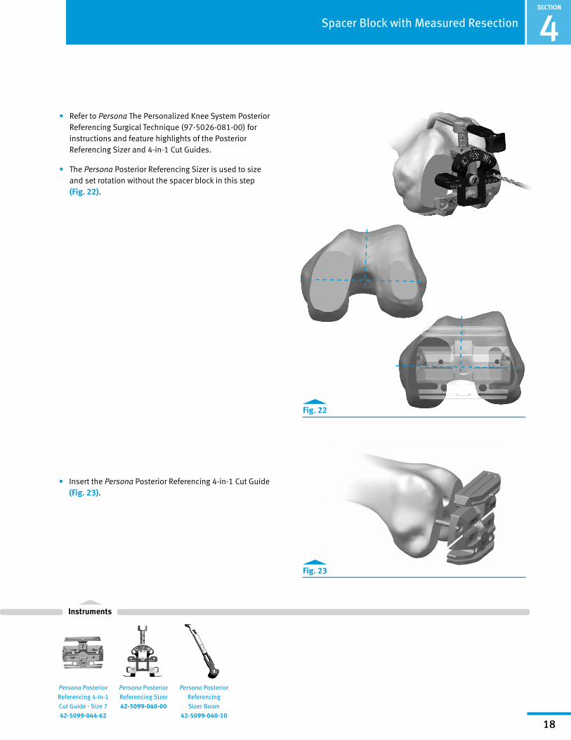
• Refer to Persona The Personalized Knee System Posterior Referencing Surgical Technique (97-5026-081-00) for instructions and feature highlights of the Posterior Referencing Sizer and 4-in-1 Cut Guides.
• The Persona Posterior Referencing Sizer is used to size and set rotation without the spacer block in this step (Fig. 22).
4Spacer Block with Measured Resection
Persona Posterior Referencing 4-in-1 Cut Guide - Size 7 42-5099-044-62
Fig. 22
Fig. 23
Persona Posterior Referencing Sizer Boom
42-5099-040-10
Persona Posterior Referencing Sizer42-5099-040-00
• Insert the Persona Posterior Referencing 4-in-1 Cut Guide (Fig. 23).

SECTION
19
Instruments
4. Verify Rotation of the Persona 4-in-1 Cut Guide and Ensure No Notching.
• Prior to resection of the posterior condyles, attach the Zimmer FuZion 4-in-1 Cut Guide Adapter to the Zimmer FuZion Spacer Block and insert into the posterior holes of the Persona Posterior Referencing 4-in-1 Cut Guide (Fig. 24).
• Zimmer FuZion Shims can be added to bottom of spacer block to increase the construct thickness and achieve the proper joint tension.
• Zimmer FuZion Shims are available for 11, 12, 13, 14, 16, 18, and 20mm construct thickness (default thickness of spacer block is 10mm).
• Check to ensure the posterior surface of the Persona Posterior Referencing 4-in-1 Cut Guide is parallel to the tibia, the angle read out is 0°, and the flexion gap is appropriate based on what was measured in extension.
• If needed, use the Persona Shift Block to adjust the Persona Posterior Referencing 4-in-1 Cut Guide rotation (2°) or AP position (1mm) prior to making any cuts with the Persona Posterior Referencing 4-in-1 Cut Guide. Place the pegs of the Persona Shift Block in the holes created by the Zimmer FuZion Sizer for the Persona Posterior Referencing 4-in-1 Cut Guide. Establish the new block position by drilling through the holes on the face of the Persona Shift Block that specifies the adjustment that is intended. Use a 3.2mm Drill to drill the holes (Fig. 25). Use the Zimmer FuZion 4-in-1 Cut Guide Adapter to verify the Persona Posterior Referencing 4-in-1 Cut Guide's new position is correct.
Caution: Be sure to put the Persona Posterior Referencing 4-in-1 Cut Guide in the new holes created by the Persona Shift Block.
4 Spacer Block with Measured Resection
Fig. 25
Persona Shift Block
Zimmer FuZion
4-in-1 Cut Guide Adapter, Left
42-5097-041-00
Persona
Shift Block 42-5099-085-10
Persona Posterior Referencing 4-in-1 Cut Guide - Size 7 42-5099-044-62
Zimmer FuZion
Spacer Block Shim, 11mm, Left
42-5097-011-11
Zimmer FuZion
Spacer Block, Left
42-5097-011-00
Fig. 24
3.2mm Drill00-5120-085-00
Zimmer FuZion 4-in-1 Cut Guide Adapter

SECTION
20
Instruments
4Spacer Block with Measured Resection
Fig. 26
Zimmer FuZion
4-in-1 Cut Guide Adapter, Left
42-5097-041-00
Persona Posterior Referencing 4-in-1 Cut Guide - Size 7 42-5099-044-62
Resection Guide00-5977-084-00
Zimmer FuZion
Spacer Block Shim, 11mm, Left 42-5097-011-11
Zimmer FuZion
Spacer Block, Left
42-5097-011-00
3.2mm Drill00-5120-085-00
• Check for notching by placing a resection guide in the anterior cut slot or by using a 3.2mm Drill in the drill hole in the anterior cut slot of the Persona Posterior Referencing 4-in-1 Cut Guide before making cuts. Change size as appropriate to avoid notching (Fig. 26).
SECTION
21
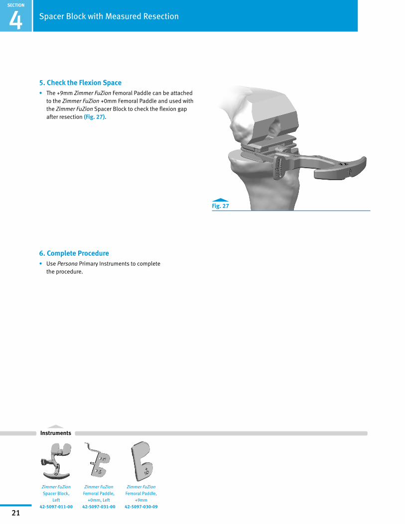
5. Check the Flexion Space• The +9mm Zimmer FuZion Femoral Paddle can be attached
to the Zimmer FuZion +0mm Femoral Paddle and used with the Zimmer FuZion Spacer Block to check the flexion gap after resection (Fig. 27).
4 Spacer Block with Measured Resection
6. Complete Procedure• Use Persona Primary Instruments to complete
the procedure.
Fig. 27
Instruments
Zimmer FuZion
Femoral Paddle, +9mm
42-5097-030-09
Zimmer FuZion Femoral Paddle,
+0mm, Left42-5097-031-00
Zimmer FuZion Spacer Block,
Left42-5097-011-00

SECTION
22
Spacer Block with Zimmer FuZion Sizer1. Perform Distal Femoral and Proximal Tibial
Resection (Fig. 28)• Verify that the cut surface of the tibia is perpendicular to
the long axis of the tibia and that the valgus angle of the distal femoral cut restores neutral leg alignment. If desired, a drop rod can be usd through the alignment hole and/or slot in the spacer block.
Note: Osteophytes can impact ligament tension. Ensure all osteophytes are removed prior to assessing soft tissues.
5Spacer Block with Zimmer FuZion™ Sizer
Fig. 28

SECTION
23
Instruments
Angle is read using the angle scale and arm of proximal attachment
Arm of proximal attachment
Zimmer FuZion Femoral Paddle,
+9mm 42-5097-030-09
Zimmer FuZion Femoral Paddle,
+0mm, Left42-5097-031-00
Zimmer FuZion
Spacer Block Shim, 11mm, Left 42-5097-011-11
Zimmer FuZion Spacer Block,
Left42-5097-011-00
5 Spacer Block with Zimmer FuZion™ Sizer
2. Extension Gap Assessment and Initial Ligament Balancing
Note: Instruments are left and right specific.
• Remove all the osteophytes and complete the initial ligament balancing. Place the leg in extension. Assemble the Zimmer FuZion Spacer Block (Fig. 29). Insert the Zimmer FuZion Spacer Block into the extension gap (Fig. 30).
• While assessing the gap, it is very important to align the spacer block's center pivot of the femoral paddle with the center of the knee and the AP Axis of the tibial (medial 1/3 of the tibial tubercle and the anterior insertion of the posterior cruciate) (Fig. 30).
Note: Use the +0mm Zimmer FuZion Femoral Paddle to evaluate the joint space prior to resection. Add the +9mm Zimmer FuZion Femoral Paddle to the +0mm Zimmer FuZion Femoral Paddle (attachment is magnetic) to evaluate the joint space after femoral condyles have been resected (Fig. 29).
• Zimmer FuZion Shims can be added to bottom of Zimmer FuZion Spacer Block to increase the construct thickness and achieve the proper joint tension (Fig. 29).
• Zimmer FuZion Shims are available for 11, 12, 13, 14, 16, 18, and 20mm construct thicknesses (default thickness of spacer block is 10mm) (Fig. 29).
• The angle scale is on the medial side of the instrument should read 0° indicating a rectangular gap. If needed, balance the extension gap using ligament release (Fig. 30).
• Note the Zimmer FuZion Spacer Block construct thickness. It will be used to create the appropriate flexion space.
Slide external dovetail (Tab A) into internal dovetail (Slot B)
1. 2.
Alignment rod features
Fig. 29
Slot BTab A
Fig. 30

SECTION
24
Instruments
Fig. 31
Side view: +0mm Paddle in the locked position (top)Side view: +9mm Paddle in the locked position (bottom)
Fig. 32
Side view: +0mm Paddle in the unlocked position (top)Side view: +9mm Paddle in the unlocked position (bottom)
Paddle release button in locked position
Paddle release button in unlocked position
Zimmer FuZion
Femoral Paddle, +9mm
42-5097-030-09
Zimmer FuZion
Femoral Paddle, +0mm, Left
42-5097-031-00
Zimmer FuZion Spacer Block,
Left42-5097-011-00
Spacer Block with Zimmer FuZion™ Sizer 5
• The Zimmer FuZion Spacer Block can be used as a conventional solid spacer block. The femoral paddle rotation can be locked at 0°, in both +0mm and +9mm configurations, by pushing the femoral paddle towards the t-handle (Fig. 31 ).
• To release, simply push the button created by the femoral paddle when it is in the lock position until it is flush with the face of the spacer (Fig. 32).

SECTION
25
Instruments
3. Flexion Gap and Setting Femoral Rotation • Remove the Zimmer FuZion Spacer Block from the
extension gap. Dissassemble the Zimmer FuZion +9mm Femoral Paddle from Zimmer FuZion +0mm Femoral Paddle. Bring the leg into 90° of flexion. Insert the Zimmer FuZion Spacer Block between the cut tibial surface and the uncut posterior condyles, as shown (Fig. 33).
• Zimmer FuZion Shims can be added to the bottom of the Zimmer FuZion Spacer Block to increase the construct thickness and achieve the proper joint tension.
• Zimmer FuZion Shims are available for 11, 12, 13, 14, 16, 18, and 20mm construct thicknesses (default thickness of spacer block is 10mm).
5 Spacer Block with Zimmer FuZion™ Sizer
Fig. 33
Fig. 34
Zimmer FuZion Sizer magnetically attaches and freely slides into position.
Zimmer FuZion Posterior Referencing
Sizer Stylus 42-5097-060-10
1.
2.
Zimmer FuZion
Posterior Referencing Sizer Drill Guide
42-5097-061-00
Zimmer FuZion
Femoral Paddle, +0mm, Left
42-5097-031-00
Zimmer FuZion
Spacer Block Shim, 11mm, Left
42-5097-011-11
Zimmer FuZion
Spacer Block, Left
42-5097-011-00
• Assemble Zimmer FuZion Sizer. Attach the Zimmer FuZion Sizer to the proximal face of the Zimmer FuZion Spacer Block. The wide flat distal face of the Zimmer FuZion Sizer will magnetically attach to the Zimmer FuZion Spacer Block (Fig. 34).

SECTION
26
Instruments
Depress the button to adjust the rotation of the sizer body if the femur is internally or over externally rotated.
Femoral sizes are staggered on both sides of the Zimmer FuZion Sizer.
Note: The Zimmer FuZion Sizer is free to slide in any direction on the proximal surface of the spacer block.
• Slide the Zimmer FuZion Sizer up to the distal femur so that the bone side of the Zimmer FuZion Sizer is sitting parallel, or flush, with the cut distal surface.
• Position the tip of the Zimmer FuZion Sizer stylus onto the anterior cortex and size the femur (Fig. 35).
Note: The Zimmer FuZion Sizer can be used to adjust the amount of femoral rotation if the natural femur is internally or over externally rotated (Fig. 36). The Zimmer FuZion Sizer offers 2° increments of adjustment. Consider adjusting rotation if the scale is outside 3-7° of external rotation. Use Whiteside's line and/or the epicondylar axis as an additional visual reference to confirm component rotation. If the collateral soft-tissue does not provide adequate stability, the surgeon should use his/her professional medical judgment to assess whether a more constraining implant/system or revision implant/system is necessary.
Spacer Block with Zimmer FuZion™ Sizer 5
Fig. 35
Zimmer FuZion Posterior Referencing
Sizer Stylus 42-5097-060-10
Zimmer FuZion
Posterior Referencing Sizer Drill Guide
42-5097-061-00
Zimmer FuZion Femoral Paddle,
+0mm, Left42-5097-031-00
Zimmer FuZion Spacer Block,
Left42-5097-011-00
Fig. 36
Medial Lateral Increase Femoral Rotation
Decrease Femoral Rotation

SECTION
27
Instruments
Fig. 37
Fig. 38
Zimmer FuZion Posterior Referencing
Sizer Stylus 42-5097-060-10
Persona Posterior Referencing 4-in-1 Cut Guide - Size 7 42-5099-044-62
Zimmer FuZion Posterior Referencing
Sizer Drill Guide 42-5097-061-00
Zimmer FuZion Femoral Paddle,
+0mm, Left42-5097-031-00
Zimmer FuZion Spacer Block,
Left42-5097-011-00
Caution: If a posterior rough cut is made do not use the angle and gap scales on the Zimmer FuZion Spacer Block.
Note: The Zimmer FuZion Sizer can only be used with the Persona Posterior Referencing 4-in-1 Cut Guides
• Use the 3.2mm Drill in the drill holes of the Zimmer FuZion Sizer to position the Posterior Referencing 4-in-1 Cut Guides.
• If needed, use the +2mm/-2mm holes to adjust the flexion space as appropriate (Fig. 37).
5 Spacer Block with Zimmer FuZion™ Sizer
• Remove Zimmer FuZion Spacer Block and Sizer.
• Insert Persona Posterior Referencing 4-in1 Cut Guide (Fig. 38).
3.2mm Drill00-5120-085-00

SECTION
28
Instruments
Persona Shift Block
42-5099-085-10
Persona Posterior Referencing 4-in-1 Cut Guide - Size 7 42-5099-044-62
Zimmer FuZion
4-in-1 Cut Guide Adapter, Left
42-5097-041-00
Zimmer FuZion
Spacer Block Shim, 11mm, Left 42-5097-011-11
Zimmer FuZion
Spacer Block, Left
42-5097-011-00
4. Verify Rotation of Persona 4-in-1 Cut Guide and Ensure No Notching
• Prior to resection of the posterior condyles, attach the Zimmer FuZion 4-in-1 Cut Guide Adapter to the Zimmer FuZion Spacer Block and insert into the posterior holes of the Persona Posterior Referencing 4-in-1 Cut Guide (Fig. 39).
• Zimmer FuZion Shims can be added to bottom of spacer block to increase the construct thickness and achieve the proper joint tension.
• Zimmer FuZion Shims are available for 11, 12, 13, 14, 16, 18, and 20mm construct thicknesses (default thickness of spacer block is 10mm).
• Check to ensure the posterior surface of the Persona Posterior Referencing 4-in-1 Cut Guide is parallel to the tibia and the angle read out is 0° and flexion gap (articular surface thickness) is appropriate based on what was measured in extension.
• If needed, use the Persona Shift Block to adjust the Persona Posterior Referencing 4-in-1 Cut Guide rotation (2°) or AP position (1mm) prior to making any cuts with the Persona Posterior Referencing 4-in-1 Cut Guide (Fig. 40). Place the pegs of the Persona Shift Block in the holes created by the Zimmer FuZion Sizer for the Persona Posterior Referencing 4-in-1 Cut Guide. Establish the new block position by drilling through the holes on the face of the Persona Shift Block that specifies the adjustment that is intended. Use a 3.2mm Drill to drill the holes. Use the Zimmer FuZion 4-in-1 Cut Guide Adapter to verify the Persona Posterior Referencing 4-in-1 Cut Guide's new position is correct.
Caution: Be sure to put the Persona Posterior Referencing 4-in-1 Cut Guide in the new holes created by the Persona Shift Block.
Spacer Block with Zimmer FuZion™ Sizer 5
Fig. 40
Fig. 39
Persona Shift Block
3.2mm Drill00-5120-085-00
Zimmer FuZion 4-in-1 Cut Guide Adapter

SECTION
29
5 Spacer Block with Zimmer FuZion™ Sizer
• Check for notching by placing a resection guide in the anterior cut slot or by using a 3.2mm Drill in the drill hole in the anterior cut slot of the Persona Posterior Referencing 4-in-1 Cut Guide before making cuts. Change size as appropriate to avoid notching (Fig. 41).
Check the Flexion Space• The +9mm Zimmer FuZion Femoral Paddle can be attached
to the Zimmer FuZion +0mm Femoral Paddle and used with the Zimmer FuZion Spacer Block to check the flexion gap after resection (Fig. 42).
5. Complete Procedure• Use Persona Primary Instruments to complete
the procedure.
Fig. 41
Fig. 42
Instruments
Zimmer FuZion Femoral Paddle,
+9mm 42-5097-030-09
Zimmer FuZion Femoral Paddle,
+0mm, Left42-5097-031-00
Zimmer FuZion Spacer Block,
Left42-5097-011-00
Resection Guide00-5977-084-00
3.2mm Drill00-5120-085-00
Persona Posterior Referencing
4-in-1 Cut Guide - Size 7
42-5099-044-62
3.2mm Drill Hole
Zimmer FuZion
4-in-1 Cut Guide Adapter, Left
42-5097-041-00

SECTION
30
Tensor with Gap Referencing Drill Guide1. Perform Distal Femoral and Proximal
Tibial Resection (Fig. 43)• Verify that the cut surface of the tibia is perpendicular
to the long axis of the tibia and the valgus angle of the distal femoral cut restores neutral leg alignment. If desired, a drop rod can be used through the alignment hole and/or slot in the tensor.
Note: Osteophytes can impact ligament tension. Ensure all osteophytes are removed prior to assessing soft tissues.
6Tensor with Gap Referencing Drill Guide
Fig. 43

SECTION
31
Instruments
3.5mm Hex Head Screwdriver
00-5120-087-00
Zimmer FuZion Tensor, Femoral Assembly, Left
42-5097-021-00
Zimmer FuZion Femoral Paddle,
+9mm 42-5097-030-09
Zimmer FuZion Tensor, Tibial
Assembly, Left42-5097-021-01
Zimmer FuZion Femoral Paddle,
+0mm, Left42-5097-031-00
6 Tensor with Gap Referencing Drill Guide
2. Extension Gap Assessment and Initial Ligament Balancing
Note: Instruments are left and right specific.
• Remove all the osteophytes and complete the initial ligament balancing. Place the leg in extension. Assemble the Zimmer FuZion Tensor with the +9mm Paddle (Fig. 44). Insert the Zimmer FuZion Tensor into the extension gap.
Note: Use the +0mm Zimmer FuZion Femoral Paddle to evaluate the joint space prior to resection. Attach the +9mm Zimmer FuZion Femoral Paddle to the +0mm Zimmer FuZion Femoral Paddle (attachment is magnetic) to evaluate the joint space after the femoral condyles have been resected (Fig. 44).
3.5mm Hex Head Screwdriver Assembly
Fig. 44
Fig. 45
Scale indicates varus/valgus and femoral rotation
Alignment Rod Features
Scale indicates articular surface thickness
Every click of the tensor pinion is 1mm.
Tensor Assembly View
+9mm Zimmer FuZion Femoral
Paddle Attachment
+0mm Zimmer FuZion Femoral Paddle
• Using 3.5mm Hex Head Screwdriver, apply the appropriate amount of force to the tensor to distract the joint (Fig 45).

SECTION
32
Instruments
Arm of proximal attachment
Angle is read using the angle scale and arm of proximal attachment
Fig. 46
Fig. 47
Read the gap size from the engrave line on the pin
• While assessing the gap, it is very important to align the tensor's center pivot of the femoral paddle with the center of the knee and the AP Axis of the tibia (medial 1/3 of the tibial tubercle and the anterior insertion of the posterior cruciate) (Fig. 46 & Fig. 48).
• The angle scale on the medial side of the instrument should read 0° indicating a rectangular gap. If needed, balance the extension gap using ligament release (Fig. 46).
• After the gap is balanced and rectangular, measure the gap distance using the gap scale on the anterior face of the Zimmer FuZion Tensor (Fig. 46).
• Note the extension gap measurement. It will be used to create the appropriate flexion space.
3. Flexion Gap and Setting Femoral Rotation• Remove the Zimmer FuZion Tensor from the extension
gap. Remove the +9mm Zimmer FuZion Femoral Paddle. Assemble the Gap Referencing Drill Guide to the Zimmer FuZion Tensor (Fig. 47).
Zimmer FuZion Gap Referencing
Drill Guide42-5097-050-00
Zimmer FuZion Femoral Paddle,
+0mm, Left42-5097-031-00
Zimmer FuZion Tensor, Tibial
Assembly, Left42-5097-021-01
Zimmer FuZion Tensor, Femoral Assembly, Left
42-5097-021-00
3.5mm Hex Head Screwdriver
00-5120-087-00
Zimmer FuZion Femoral Paddle,
+9mm 42-5097-030-09
6Tensor with Gap Referencing Drill Guide

SECTION
33
Instruments
• Bring the leg into 90° of flexion. Insert the Zimmer FuZion Tensor between the cut tibial surface and the uncut posterior condyles, as shown (Fig. 48).
• Using the 3.5mm Hex Head Screwdriver, apply the appropriate amount of force to distract the joint (Fig. 48).
Note: The medial collateral ligament will engage first. The femur will then rotate internally, tightening the lateral collateral until equal tension of both is achieved.
Caution: If a posterior rough cut is made do not use the angle and gap scales on the Zimmer FuZion Tensor.
• Ensure that the scale reads between 3-7° of rotation using Whiteside's line and/or the epicondylar axis as an additional visual reference to confirm component rotation (Fig. 48). If the collateral soft-tissue does not provide adequate stability, the surgeon should use his/her professional medical judgment to assess whether a more constraining implant/system or revision implant/system is necessary.
• Double check the posterior cut creates a flexion gap within 2mm of the extension gap (Fig. 48).
Caution: Double check, when measuring in flexion, that the distance on the tensor scale is within 2mm of what was measured in extension. Remember to use the +0mm Zimmer FuZion Femoral Paddle to evaluate the joint space prior to resection and +9mm Zimmer FuZion Femoral Paddle to evaluate the joint space after resection (Fig. 48).
• Select the holes on the drill guide that match the gap measured in extension. Ensure the Zimmer FuZion Gap Referencing Drill Guide is parallel, or flush, with the face of the distal femur. Drill the holes using the 3.2mm Drill. These will position the Persona Posterior Referencing 4-in-1 Cut Guide (Fig. 49).
Note: The orientation of the drill guide can be rotated 180° to change the offset of the distal femoral contacting surface by 10mm.
Note: The gap referencing drill guide can only be used with the Persona Posterior Referencing 4-in-1 Cut Guides.
Note: The Gap Referencing Drill Guide is designed to ensure a rectangular flexion space without consideration of the posteriorcondylar position.
Fig. 49
Zimmer FuZion Gap Referencing
Drill Guide42-5097-050-00
Zimmer FuZion Femoral Paddle,
+0mm, Left42-5097-031-00
Zimmer FuZion
Tensor, Tibial Assembly, Left
42-5097-021-01
Zimmer FuZion Tensor, Femoral Assembly, Left
42-5097-021-00
3.5mm Hex Head Screwdriver
00-5120-087-00
Zimmer FuZion
Femoral Paddle, +9mm
42-5097-030-09
6 Tensor with Gap Referencing Drill Guide
Persona Posterior Referencing 4-in-1 Cut Guide - Size 7 42-5099-044-62
Stay between 3-7° of rotation.
Distance should be within 2mm of extension measurement.
Fig. 48
3.2mm Drill00-5120-085-00

SECTION
34
Instruments
6Tensor with Gap Referencing Drill Guide
4. Size Femur• Assemble the Posterior Referencing Sizer Boom with
the Posterior Referencing Sizer (Fig. 50).
Note: The Persona Posterior Referencing Sizer is only intended to provide an estimated component size at this point in the surgical technique. Do not use the sizer to drill holes for the 4-in-1 Cut Guide.
• Refer to Persona The Personalized Knee System Posterior Referencing Surgical Technique (97-5026-081-00) for instructions and feature highlights of the Posterior Referencing Sizer and 4-in-1 Cut Guides.
• Use the Persona Posterior Referencing Sizer to size the femur (Fig. 51).
• Insert the Persona Posterior Referencing 4-in-1 Cut Guide (Fig. 51).
Fig. 51
Fig. 50
Insert and Rotate
Persona Posterior Referencing Sizer
Boom 42-5099-040-10
Persona Posterior Referencing Sizer42-5099-040-00
Persona Posterior Referencing 4-in-1 Cut Guide - Size 7 42-5099-044-62

SECTION
35
Instruments
6
5. Verify Rotation of Persona 4-in-1 Cut Guide and Ensure No Notching
• Prior to resection of the posterior condyles, attach the Zimmer FuZion 4-in-1 Cut Guide Adapter to the Zimmer FuZion Tensor and insert into the posterior holes of the Persona Posterior Referencing 4-in-1 Cut Guide (Fig. 52).
• Using the 3.5mm Hex Head Screwdriver apply the appropriate amount of force to distract the joint
• Check to ensure the posterior surface of the Persona Posterior Referencing 4-in-1 Cut Guide is parallel to the tibia and the angle read out is 0° and flexion gap is appropriate based on what was measured in extension.
• If needed, use the Persona Shift Block to adjust the Persona Posterior Referencing 4-in-1 Cut Guide rotation (2°) or AP position (1mm) prior to making any cuts with the Persona Posterior Referencing 4-in-1 Cut Guide. Place the pegs of the Persona Shift Block in the holes created by the Zimmer FuZion Sizer for the Persona Posterior Referencing 4-in-1 Cut Guide. Establish the new block position by drilling through the holes on the face of the Persona Shift Block that specifies the adjustment that is intended. Use a 3.2mm Drill to drill the holes. Remove the shift block, Place the Persona Posterior Referencing 4-in-1 Cut Guide back on the bone (Fig. 53.). Use the Zimmer FuZion 4-in-1 Cut Guide Adapter to verify the Persona Posterior Referencing 4-in-1 Cut Guide's new position is correct.
Caution: Be sure to put the Persona Posterior Referencing 4-in-1 Cut Guide in the new holes created by the Persona Shift Block.
Tensor with Gap Referencing Drill Guide
Resection Guide00-5977-084-00
Persona Posterior Referencing 4-in-1 Cut Guide - Size 7 42-5099-044-62
Fig. 52
Zimmer FuZion Tensor, Femoral Assembly, Left
42-5097-021-00
Zimmer FuZion 4-in-1 Cut Guide
Adapter, Left42-5097-041-00
Zimmer FuZion Tensor, Tibial
Assembly, Left42-5097-021-01
Fig. 53
Persona Shift Block
3.5mm Hex Head Screwdriver
00-5120-087-00
Persona Shift Block
42-5099-085-10
3.2mm Drill00-5120-085-00

SECTION
36
3.2mm Drill Hole
Resection Guide00-5977-084-00
Persona Posterior Referencing 4-in-1 Cut Guide - Size 7 42-5099-044-62
Fig. 54
Zimmer FuZion Tensor, Femoral Assembly, Left
42-5097-021-00
Zimmer FuZion Femoral Paddle,
+9mm 42-5097-030-09
Zimmer FuZion Tensor, Tibial
Assembly, Left42-5097-021-01
Zimmer FuZion Femoral Paddle,
+0mm, Left42-5097-031-00
Fig. 55
• Check for notching by placing a resection guide in the anterior cut slot or by using a 3.2mm Drill in the drill hole in the anterior cut slot of the Persona Posterior Referencing 4-in-1 Cut Guide before making cuts. Change size as appropriate to avoid notching (Fig. 54).
Caution: By matching the extension gap the posterior condylar resection may be significantly greater or less than the standard 9mm posterior resection.
6Tensor with Gap Referencing Drill Guide
3.5mm Hex Head Screwdriver
00-5120-087-00
3.2mm Drill00-5120-085-00
6. Check the Flexion Space• The +9mm Zimmer FuZion Femoral Paddle can be attached
to the Zimmer FuZion +0mm Femoral Paddle and used with the Zimmer FuZion Tensor to check the flexion gap after resection (Fig. 55).
7. Complete Procedure• Use Persona Primary Instruments to complete
the procedure.
Instruments
SECTION
37
Transitioning from CR to PS• The transition from Cruciate Retaining (CR) component to a
Posterior Stabilized (PS) component is a fundamental shift in philosophy. Both systems utilize component geometry and positioning to optimize kinematics and survivorship. Both systems have unique approaches to implantation and both systems are successfully used.
• Zimmer’s Persona Personalized Knee System CR component carries its attributes from Zimmer’s Natural-Knee® System. The geometry of the femoral component utilizes a “big wheel/ little wheel” design that provides rollback replicating the natural kinematics of the knee. In addition, the tibial polyethelene is more conforming medially and less conforming laterally. The slope of the poly is recommended to be 7° to align to the slope of the natural anatomy. The geometry and cuts are intended to put the components in a position to work with the natural anatomy given the preservation of the cruciate ligament, to provide a natural feel and motion.
• A transition from CR to a posterior cruciate substituting constraint within this system is typically an Ultra-Congruent (UC) polyethelene tibial insert design that drives motion with a deep concave dish in the medial compartment. The tibial insert also has pronounced anterior and posterior lips to provide anterior/posterior constraint and prevent posterior roll off. The transition to the UC is seamless. The CR femoral component is used with the UC. Removal of the PCL is the only requirement when using the UC component. The UC tibial polyethelene is attached to the tibial baseplate implant in the same manner as the CR tibial polyethelene.
• Zimmer’s Persona Personalized Knee System PS component carries its attributes from Zimmer’s NexGen® Knee System. The geometry of the femoral component is symmetric, with a posterior condyle that’s 1mm thicker than the distal condyle. The post that is used as a substitute for the posterior cruciate engages the cam of the femoral component in mid-flexion and forces femoral rollback. The recommended tibial slope for this component 3°. The geometry and cuts are intended to drive motion.
• In the situations when starting with a CR approach and determining in-situ that a higher level of constraint is needed, certain considerations should be used to ensure that a stable knee with full extension is enabled.
• The 1mm thicker posterior condyle of the PS femoral component and the box that houses the PS post tibial polyethelene will require some additional preparation when making the transition.
• Considerations transitioning from CR to a PS design: 1. Utilize a UC tibial insert 2. Recut the tibial slope (from 7 to 3°) 3. Remove the posterior cruciate ligament
7 Transitioning from CR to PS

SECTION
38
8Balancing Matrix
Extension
Flex
ion
Tight OK Loose
Tigh
t
1 2 3
• Reduce articular surface thickness
• Release PCL, Change to a UC
• Down size femoral component increase articular surface thickness
• Recut tibia • For Anterior Referencing: Down size femoral component
• For Anterior Referencing: Down size femoral component; increase tibial articular surface thickness
• For Posterior Referencing: Down size femoral component and shift anterior
• For Posterior Referencing: Down size femoral component and shift anterior; increase tibial articular surface thickness
OK
4 5 6
• Release the posterior capsule from the femur
OK
• Down size femoral component, increase articular surface thickness
• Resect more distal femur (will elevate the joint line)
• For Anterior Referencing: Down size femoral component; increase tibial articular surface thickness
• For Posterior Referencing: Down size femoral component and shift anterior; increase tibial articular surface thickness
Loos
e
7 8 9
• For Anterior Referencing: Up size femoral component
• For Anterior Referencing: Up size femoral component
• Increase articular surface thickness
• For Posterior Referencing: Up size femoral component and shift posterior
• For Posterior Referencing: Up size femoral component and shift posterior
• Reduce articular surface thickness
• Posterior release, increase articular surface thickness
• Posterior release, increase articular surface thickness
Fig. 56
Balancing MatrixCheck Extension Gap
• After the proximal tibia and distal femur have been resected, the extension gap can be evaluated using the Zimmer FuZion Spacer Block or the Zimmer FuZion Tensor. Position the knee in full extension. The distal thickness of the Persona femoral component is 9mm and the minimum Persona tibial articular surface/baseplate construct is 10mm. If the Zimmer FuZion Spacer Block with the +9mm Paddle (19mm) does not fit into the resected joint space in extension, it will be necessary to remove additional bone from the femur.
• Use the Zimmer FuZion Spacer Block or the Zimmer FuZion Tensor to check the extension gap. Insert the Zimmer FuZion Spacer Block or Tensor between the resected surfaces of the femur and tibia. If necessary, add Zimmer FuZion Shims to the Zimmer FuZion Spacer Block or adjust the Zimmer FuZion Tensor until the desired soft tissue tension is obtained. Use the alignment rod to check overall alignment. Varus and valgus stress can be used to evaluate ligament stability. Ligament releases can be performed, at this point, to create an extension gap that is rectangular. When the extension gap is balanced, proceed to size femur, establish external rotation and finish the femoral cuts.
Check Flexion Gap
• After the femoral finishing cuts have been completed and with the knee in 90° flexion, use the Zimmer FuZion Spacer Block or the Zimmer FuZion Tensor to check ligament balance and joint alignment in flexion. Check ligament balance. If necessary, insert progressively thicker Zimmer FuZion Spacer Block Shims underneath Zimmer FuZion Spacer Block or adjust the Zimmer FuZion Tensor until the desired soft tissue tension is obtained.
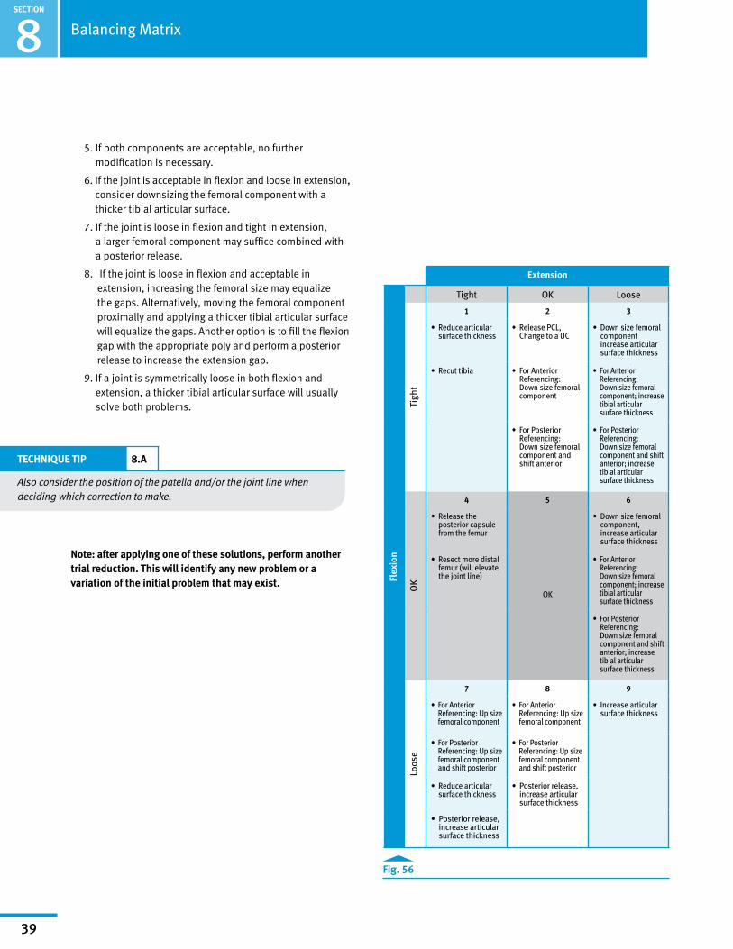
Correcting Gaps (Fig. 56):
1. If a knee is too tight in both flexion and extension, reducing the height of the tibial articular surface may be sufficient to balance the construct. If the thinnest tibial articular surface is too tight, resect more tibia.
2. If the knee is tight in flexion but acceptable in extension, two options exist. One option is to release the PCL. If the PCL is absent, change constraint to UC. The second option is to downsize the femoral component.
3. If the joint is loose in extension and tight in flexion one option is to use a smaller sized femoral component possibly with a thicker polyethylene component.
4. If the joint is acceptable in flexion but tight in extension, two options exist. One is to release the posterior capsule from the femur. Another alternative is to resect more distal femoral bone. This moves the femoral component proximally on the femur at the expense of elevating the joint line.
SECTION
39
Extension
Flex
ion
Tight OK Loose
Tigh
t
1 2 3
• Reduce articular surface thickness
• Release PCL, Change to a UC
• Down size femoral component increase articular surface thickness
• Recut tibia • For Anterior Referencing: Down size femoral component
• For Anterior Referencing: Down size femoral component; increase tibial articular surface thickness
• For Posterior Referencing: Down size femoral component and shift anterior
• For Posterior Referencing: Down size femoral component and shift anterior; increase tibial articular surface thickness
OK
4 5 6
• Release the posterior capsule from the femur
OK
• Down size femoral component, increase articular surface thickness
• Resect more distal femur (will elevate the joint line)
• For Anterior Referencing: Down size femoral component; increase tibial articular surface thickness
• For Posterior Referencing: Down size femoral component and shift anterior; increase tibial articular surface thickness
Loos
e
7 8 9
• For Anterior Referencing: Up size femoral component
• For Anterior Referencing: Up size femoral component
• Increase articular surface thickness
• For Posterior Referencing: Up size femoral component and shift posterior
• For Posterior Referencing: Up size femoral component and shift posterior
• Reduce articular surface thickness
• Posterior release, increase articular surface thickness
• Posterior release, increase articular surface thickness
Fig. 56
Balancing Matrix8
5. If both components are acceptable, no further modification is necessary.
6. If the joint is acceptable in flexion and loose in extension, consider downsizing the femoral component with a thicker tibial articular surface.
7. If the joint is loose in flexion and tight in extension, a larger femoral component may suffice combined with a posterior release.
8. If the joint is loose in flexion and acceptable in extension, increasing the femoral size may equalize the gaps. Alternatively, moving the femoral component proximally and applying a thicker tibial articular surface will equalize the gaps. Another option is to fill the flexion gap with the appropriate poly and perform a posterior release to increase the extension gap.
9. If a joint is symmetrically loose in both flexion and extension, a thicker tibial articular surface will usually solve both problems.
TECHNIQUE TIP 8.A
Also consider the position of the patella and/or the joint line when deciding which correction to make.
Note: after applying one of these solutions, perform another trial reduction. This will identify any new problem or a variation of the initial problem that may exist.

SECTION
40
9Persona Knee Surgical Technique Library
Surgical Technique Name Literature Number
Persona The Personalized Knee System Surgical Technique 97-5026-001-00
Persona The Personalized Knee System Posterior Referencing Surgical Technique 97-5026-081-00
Persona The Personalized Knee System Trabecular Metal™ Tibia Surgical Technique 97-5026-027-00
Persona The Personalized Knee System Trabecular Metal Femur Surgical Technique 97-5026-070-00
Persona Knee Surgical Technique Library

Contact your Zimmer representative or visit us at www.zimmer.com
Disclaimer
This documentation is intended exclusively for physicians and is not intended for laypersons.Information on the products and procedures contained in this document is of a general nature and does not represent and does not constitute medical advice or recommendations. Because this information does not purport to constitute any diagnostic or therapeutic statement with regard to any individual medical case, each patient must be examined and advised individually, and this document does not replace the need for such examination and/or advice in whole or in part.
Please refer to the package inserts for important product information, including, but not limited to, contraindications, warnings, precautions, and adverse effects.
97-5026-046-00 Rev. 1 MC126382 08/30/16 ©2016 Zimmer, Inc.