Zero Discharge Water Management for Horizontal Shale Gas ...
46
Zero Discharge Water Management for Horizontal Shale Gas Well Development Final Report Start Date: October 1, 2009 End Date: March 31, 2012 Authors: Paul Ziemkiewicz, PhD Jennifer Hause Raymond Lovett, PhD David Locke Harry Johnson Doug Patchen, PG Report Date Issued: June 2012 DOE Award #: DE-FE0001466 Submitting Organization: West Virginia Water Research Institute West Virginia University PO Box 6064 Morgantown, WV 26506-6064 FilterSure, Inc. PO Box 1277 McLean, VA 22101 ShipShaper, LLP PO Box 2 Morgantown, WV 26507
Transcript of Zero Discharge Water Management for Horizontal Shale Gas ...

Zero Discharge Water Management for Horizontal Shale Gas Well Development
Final Report
Start Date: October 1, 2009
End Date: March 31, 2012
Authors: Paul Ziemkiewicz, PhD
Jennifer Hause
Raymond Lovett, PhD
David Locke
Harry Johnson
Doug Patchen, PG
Report Date Issued: June 2012
DOE Award #: DE-FE0001466
Submitting Organization: West Virginia Water Research Institute
West Virginia University
PO Box 6064
Morgantown, WV 26506-6064
FilterSure, Inc.
PO Box 1277
McLean, VA 22101
ShipShaper, LLP
PO Box 2
Morgantown, WV 26507

2 | P a g e
Acknowledgment "This material is based upon work supported by the Department of Energy under Award Number
DE-FE0001466."
Disclaimer "This report was prepared as an account of work sponsored by an agency of the United States
Government. Neither the United States Government nor any agency thereof, nor any of their
employees, makes any warranty, express or implied, or assumes any legal liability or
responsibility for the accuracy, completeness, or usefulness of any information, apparatus,
product, or process disclosed, or represents that its use would not infringe privately owned rights.
Reference herein to any specific commercial product, process, or service by trade name,
trademark, manufacturer, or otherwise does not necessarily constitute or imply its endorsement,
recommendation, or favoring by the United States Government or any agency thereof. The
views and opinions of authors expressed herein do not necessarily state or reflect those of the
United States Government or any agency thereof."
Abstract Hydraulic fracturing technology (fracking), coupled with horizontal drilling, has facilitated
exploitation of huge natural gas (gas) reserves in the Devonian-age Marcellus Shale Formation
(Marcellus) of the Appalachian Basin. The most-efficient technique for stimulating Marcellus
gas production involves hydraulic fracturing (injection of a water-based fluid and sand mixture)
along a horizontal well bore to create a series of hydraulic fractures in the Marcellus. The
hydraulic fractures free the shale-trapped gas, allowing it to flow to the well bore where it is
conveyed to pipelines for transport and distribution.
The hydraulic fracturing process has two significant effects on the local environment. First,
water withdrawals from local sources compete with the water requirements of ecosystems,
domestic and recreational users, and/or agricultural and industrial uses. Second, when the
injection phase is over, 10 to 30% of the injected water returns to the surface. This water
consists of flowback, which occurs between the completion of fracturing and gas production, and
produced water, which occurs during gas production. Collectively referred to as returned frac
water (RFW), it is highly saline with varying amounts of organic contamination. It can be
disposed of, either by injection into an approved underground injection well, or treated to remove
contaminants so that the water meets the requirements of either surface release or recycle use.
Depending on the characteristics of the RFW and the availability of satisfactory disposal
alternatives, disposal can impose serious costs to the operator. In any case, large quantities of
water must be transported to and from well locations, contributing to wear and tear on local
roadways that were not designed to handle the heavy loads and increased traffic. The search for a
way to mitigate the situation and improve the overall efficiency of shale gas production
suggested a treatment method that would allow RFW to be used as make-up water for successive

3 | P a g e
fracs. RFW, however, contains dissolved salts, suspended sediment and oils that may interfere
with fracking fluids and/or clog fractures. This would lead to impaired well productivity. The
major technical constraints to recycling RFW involves: identification of its composition,
determination of industry standards for make-up water, and development of techniques to treat
RFW to acceptable levels. If large scale RFW recycling becomes feasible, the industry will
realize lower transportation and disposal costs, environmental conflicts, and risks of interruption
in well development schedules.

4 | P a g e
Table of Contents Acknowledgment ............................................................................................................................ 2
Disclaimer ....................................................................................................................................... 2
Abstract ........................................................................................................................................... 2
Overview ......................................................................................................................................... 6
Project Structure.............................................................................................................................. 7
Phase I ......................................................................................................................................... 7
Recommendations of the Industry Contact Group.................................................................. 7
Table 1: Industry Contact Group Chemical Criteria for Frac Water Make-up ............... 8
Phase II........................................................................................................................................ 9
Phase I: ............................................................................................................................................ 9
Filtration with Pretreatment ............................................................................................................ 9
Dissolved Solids Removal .......................................................................................................... 9
Table 2: Costs of Various Treatment Methods.............................................................. 10
Figure 1: Comparison of Cost and Efficiency for Nanofiltration and RO ...................... 11
Figure 2: Comparison of Cost and Flow of Nanofiltration and RO ................................ 11
Figure 3: Comparison of Cost and Electricity Cost of Nanofiltration and RO ............... 12
Table 3: Chemical Results of Raw Samples of RFW ................................................... 13
Salts Removal Research ............................................................................................................ 13
Table 4: Frac Water Treatment Using 44% 2-propanol ................................................ 14
Table 5: Frac Water Evaluated w/ Ammonia (Bottle Method, mean of 3 trials) .......... 15
Table 6: Frac Water Evaluated w/ 2-propanol (Bottle Method, mean of 3 trials) ......... 16
Table 7: Frac Water Evaluated w/ 2-propanol (Beaker Method, mean of 3 trials) ....... 17
Laboratory Verification of PDU ............................................................................................... 17
Figure 4: Media Testing of PDU for Treating Marcellus RFW ...................................... 18
Table 8: Summary of PDU and Laboratory Test Data .................................................. 19
Figure 5: PSD Before and After FilterSure Filtration of a RFW Sample ....................... 20
Figure 6: Particle Size in Raw and EC-Treated Marcellus RFW .................................... 21
Filtration without Pretreatment ..................................................................................................... 22
Figure 7: Predicting Stabilized Frac Water TDS when Recycling RFW .............. 24
Table 9: RFW Dilution Model ...................................................................................... 25
Phase II: ........................................................................................................................................ 25
Mobile Treatment Unit Design, Construction and Operations ..................................................... 25
Figure 8: MTU General Arrangement ............................................................................. 26

5 | P a g e
Figure 9: Mobile Treatment Unit Piping Schematic Diagram ........................................ 27
Figure 10: Finished Exterior View of MTU ..................................................................... 27
Figure 11: Completed Interior View of MTU ................................................................... 28
Figure 12: Particle Size Distribution Results .................................................................... 29
Table 10: Filtration Results of Filtered RFW Samples .................................................... 30
Field Trials .................................................................................................................................... 30
Site 1: Utica Shale Site .......................................................................................................... 30
Figure 13: On Location at Utica Shale Site in Ohio ......................................................... 31
Figure 14: Oil/Polymer Mixture Treated by MTU ........................................................... 32
Figure 15: MTU Control Panel ......................................................................................... 33
Figure 16: Control Panel Close-Up View ......................................................................... 33
Figure 17: Pressure Drop Measurements of MTU in Operation ....................................... 34
Figure 18: Day 1 through Day 6 Filtration Rates and Pressures ....................................... 35
Figure 19: Filtration Rate and Pressure, Days 1 through 9 ............................................... 36
Lessons Learned from Site 1..................................................................................................... 37
Site 2: Marcellus Shale Site ................................................................................................... 37
Figure 20: Marcellus Shale Site, West Virginia ................................................................ 38
Figure 21: Water Treated for Fracturing Stages ............................................................... 39
Figure 22: Rate and Pressure Data during Water Treatment ............................................ 40
Figure 23: Influent and Effluent PSD from West Virginia RFW ..................................... 41
Table 11: Marcellus Shale Site Water Chemistry ............................................................ 42
Lessons Learned........................................................................................................................ 42
Project Summary ........................................................................................................................... 42
Table 12: RFW Chemical Analyses................................................................................. 43
Acronyms, Abbreviations and Units of Measurement .................................................................. 45

6 | P a g e
Overview Shale gas production depends on the creation of permeability within an otherwise nearly
impermeable rock formation. Two technologies have been applied to produce natural gas from
tight shale formations: directional/horizontal drilling and hydraulic fracturing. Hydraulic
fracturing (fracking) uses large volumes of water to create numerous channels within the shale
formation. Sand, pumped with the water, props open the hydraulic fractures, thus providing
multiple, permeable flow paths for the natural gas.
Terminology used throughout this report to describe various types of water used in the fracking
process includes:
1. Frac water – fluid prepared to carry sand (proppant) down-hole under high pressure to
create fracs (fissures) in the shale formation;
2. Flowback water – water that returns to the well head in advance of gas production;
3. Produced water – water that returns to the well head with gas during production; and
4. Return frac water (RFW) – flowback and produced water.
RFW is highly variable, changing from well to well and also as a function of time. Besides
water and sand, frac water contains a number of chemical additives with the end purpose to
enhanced gas production. Unless saline RFW is used to make up the frac water, the frac water
will have a low salinity. Flowback water contains a high proportion of the frac water. The
salinity of produced water is substantially higher than flowback water, probably due to the longer
formation residence time in which the water comes into contact with the formation salts. The
Marcellus is known to be desiccated. Otherwise, it would undergo plastic deformation rather
than fracture under pressure. Exceptions might occur where the well bore encounters a non-
target formation; but, most of the water that returns from the well is the original injected water,
or frac water. Our use of the term RFW recognizes in actual operations, flowback and produced
waters are often mixed or otherwise managed as a single commodity.
The hydraulic fracturing process has two significant effects on the local environment. First,
water withdrawals from local sources compete with the water requirements of ecosystems,
domestic and recreational users, and/or agricultural and industrial uses. Second, when the
injection phase is over, 10 to 30% of the injected water returns to the surface. This water
consists of flowback, which occurs between the completion of fracturing and gas production, and
produced water, which occurs during gas production. Collectively referred to as returned frac
water (RFW), it is highly saline with varying amounts of organic contamination. It can be
disposed of, either by injection into an approved underground injection well, or treated to remove
contaminants so that the water meets the requirements of either surface release or recycle use.
Depending on the characteristics of the RFW and the availability of satisfactory disposal
alternatives, disposal can impose serious costs to the operator. In any case, large quantities of
water must be transported to and from well locations, contributing to wear and tear on local
7 | P a g e
roadways that were not designed to handle the heavy loads and increased traffic. The search for a
way to mitigate the situation and improve the overall efficiency of shale gas production
suggested a treatment method that would allow RFW to be used as make-up water for successive
fracs. RFW, however, contains dissolved salts, suspended sediment and oils that may interfere
with fracking fluids and/or clog fractures. This would lead to impaired well productivity. The
major technical constraints to recycling RFW involves: identification of its composition,
determination of industry standards for make-up water, and development of techniques to treat
RFW to acceptable levels. If large scale RFW recycling becomes feasible, the industry will
realize lower transportation and disposal costs, environmental conflicts, and risks of interruption
in well development schedules.
On October 1, 2009, the United States Department of Energy’s (DOE) National Energy
Technology Laboratory (NETL) awarded West Virginia University (WVU) a cost-sharing
contract to evaluate techniques to be used or adapted to treat RFW. The project resulted from a
DOE Funding Opportunity Announcement (FOA) to encourage research of methods to managing
hydraulic fracturing water withdrawals and RFW from gas development in the Marcellus.
Filtration was considered a critical step in treating RFW for recycle. In developing the project
for DOE, WVU partnered with FilterSure, Inc. a developer of a multi-media filter. The project
was designed to characterize RFW, identify industry standards for make-up water, evaluate
treatment methods, and determine if pairing a technology with filtration was necessary and
economically feasible to treat RFW prior to recycling for subsequent fracking operations.
Project Structure
Phase I Phase I objectives included the determination of water quality requirements for frac water make-
up by compiling information on hydraulic fracturing practices, shale gas production practices,
and associated problems in the Appalachian shale formations. This led to the development and
adaptation of advanced water treatment and filtration technologies that would convert the RFW
into a usable substitute of fresh water for hydraulic fracturing. A Technology Status Report was
compiled and provided an overview of current industry practices and associated costs to
treat and/or dispose of RFW. The analysis indicated treatment and reuse of RFW for
another drilling operation was a promising water management option and focused the
project on treatment toward that goal.
Recommendations of the Industry Contact Group An Industry Contact Group was identified and a detailed questionnaire was sent to the members.
Responses yielded valuable information regarding RFW volumes and criteria necessary for
recycling. The Industry Contact Group provided access to well development sites, water
samples for testing by the FilterSure process demonstration unit (PDU) and invaluable advice

8 | P a g e
regarding configuration of our field-deployable technology to match the contingencies of field
operations. Some key results from discussions with the Industry Contact Group included:
slickwater hydraulic fracturing was confirmed as the dominant type of stimulation
treatment;
water demand for most horizontal wells range from about 4 to 6 million gallons, with up
to 10 stages, and as much as 250 tons of sand per stage;
vertical well hydraulic fracturings are similar in size to a single horizontal well stage,
500,000+ gallons, usually in a single stage, with a total of 250 to 500 tons of sand;
RFW is approximately 10-30% of the amount injected. Flow is greatest during the first
few days of water flow back and greatly reduced after the first week to 10 days, with
initial flow back rates averaging 3,000 to 5,000 barrels per day (90 to 150 gallons per
minute (gpm)) and declining to less than a barrel per day after 60 days; and
horizontal and vertical fracs are both successful but horizontal wells appear to provide
better economics.
Industry standards for acceptable recycle water quality standards continued to evolve. The
consensus from the Industry Contact Group concerning acceptable water quality for recycled
RFW indicated total suspended solids (TSS) below 20 microns along with a range of other
parameters presented in Table 1. The TSS criteria reflects concerns with sediment accumulating
in pores and the well bore while the chemical water quality parameters are thought to play a role
in interfering with the performance of the frac water or with scale formation.
Table 1: Industry Contact Group Chemical Criteria for Frac Water Make-up
Chemical Parameter Maximum Value (mg/L)*
TDS 50,000
Hardness 26,000
HCO3 300
SO4 50
Cl 45,000
Na 36,000
Ca 8,000
Mg 1,200
K 1,000
Fe 10
Ba 10
Sr 10
Mn 10
*Requirements of Industry Contact Group Members

9 | P a g e
Industry also required a treatment system with minimal operational and maintenance needs and a
small footprint with minimal mobilization and de-mobilization requirements. Upon review of
the laboratory tests results and multiple discussion sessions with Industry representatives, the
project team determined that the multi-media filtration system was a necessary step in any
treatment scheme. Removal of dissolved solids was considered important but not critical since
most of the criteria in Table 1 could be achieved through dilution with fresh water make-up.
Nonetheless, the project proceeded with two salt removal approaches: electro-coagulation and a
novel process in the conceptual stage of development.
Industry Contact Group recommendations were critical in refining project objectives. The
testing and review of various water treatment technologies during Phase I of the project allowed
the WVU project team to identify two options with potential for on-site treatment and recycling
of RFW:
1. Filtration to reduce suspended solids, and
2. Electro-coagulation (EC) to determine whether or not it could significantly reduce
dissolved salts.
Phase II Phase II of this project consisted of the design, fabrication and field deployment of a mobile
treatment unit (MTU). The objective was to demonstrate a practical technology for TSS removal
under actual field operating conditions. A project goal was for the treatment system design to
meet the needs of industry while providing a level of environmental protection and adaptability
for future water quality and quantity criteria. The successful development of a technology to treat
and recycle RFW will advance shale gas development through improved economics and
environmental impacts. Improved economics will be achieved by reducing the amount of
trucking and disposal of RFW and costs associated with these activities. By reusing the RFW for
subsequent hydraulic fractures, the need for fresh water will be reduced. The better you treat the
RFW, the higher the blend ratio with fresh water, the less dependence and strain on local water
resources, and the less impact on local infrastructure and the surrounding environment.
Phase I:
Filtration with Pretreatment Early in the project, it was decided to test if filtration, which removes suspended solids but few
dissolved solids, would benefit by coupling with a process for removing salts. Various processes
were examined that included reverse osmosis (RO), nanofiltration, and electro-coagulation (EC).
Dissolved Solids Removal A WVU-developed computer program that calculates the unit costs of various treatment methods
was revised with the addition of new treatment methods (such as nanofiltration and EC) and

10 | P a g e
updated costs. Table 2 shows costs per 1000 gallons for a number of treatment options utilized
to manage RFW, including EC. The EC method appeared to be competitively priced among the
various options.
Table 2: Costs of Various Treatment Methods
Treatment Method $ per1000 gallons
Surface disposal $0.07
Deep injection well - existing $0.66
Evaporation/infiltration pond w/ spray $0.99
Spray Irrigation $1.08
Microfiltration $1.36
Evaporative pond - Lined-Spray $1.97
Electro-coagulation $2.00
Shallow injection/aquifer renewal $2.85
Evaporative pond/infiltration $2.98
Water hauling $4.82
Deep injection well - new $5.64
Nanofiltration $6.15
Reverse Osmosis $6.94
Evaporative pond - Lined $27.56
Figures 1 through 3 detail some of the initial investigations comparing reverse osmosis and
nanofiltration, the former removing all ions while the latter only removed multi-valent ions.
These are two proposed technologies for total dissolved solids (TDS) reduction or removal. The
graphs compare cost versus process efficiency, cost versus flow, and cost versus electricity cost.
In all instances, nanofiltration was cheaper because of its lower pressure requirements. The rise
in cost at low efficiency for the first plot is due to increasing reject disposal costs. Low flow also
increases the cost due to the fixed costs associated with the system. The increase in cost due to
electricity rates is almost linear.

11 | P a g e
Figure 1: Comparison of Cost and Efficiency for Nanofiltration and RO
Figure 2: Comparison of Cost and Flow of Nanofiltration and RO

12 | P a g e
Figure 3: Comparison of Cost and Electricity Cost of Nanofiltration and RO
To accurately characterize RFW, the project team analyzed a number of samples provided by the
Industry Contact Group. The samples represented RFW from operating sites in New York,
Pennsylvania and West Virginia. The samples were drawn from storage tanks or pits and
represented a mixture of flowback and produced water. Five samples from the Marcellus and
one sample from the Utica shale were tested. Table 3 provides a summary of the chemistry of
six raw RFW samples used in this study.

13 | P a g e
Table 3: Chemical Results of Raw Samples of RFW
RFW #1
RFW #2
RFW #3
RFW #4
RFW #5
RFW #6
pH 7.46 6.1 7.4 6.3 6.3 6.7
Conductivity 23655 16807 66300 190100 183000 13900
SO4 99 71 28 nd 414 19
Fe 37 27 37 59 30 27
Ca 319 1749 1640 19487 12800 698
Mg 31 122 193 1257 1470 60
Na 3550 2863 8560 35500 33700 2060
K nd 57 243 479 444 43
Sr 0.011 0.011 301 3559 1440 51
Ba 27 0 175 1641 176 14
Cl 6575 7172 17100 112457 65000 4600
TSS 44 220 99 74 570 25
TDS 16559 11765 46410 133070 128100 9730
Hardness 923 4870 4890 53836 38000 1990
Oil & Grease 5 49 5 33 nd nd
nd = not detected
Salts Removal Research Removal of highly soluble ions is difficult. As mentioned, reverse osmosis and nano-filtration
are able to remove the ions at a high cost. Electro-coagulation was found to be ineffective.
Preliminary research to determine the technical feasibility of using methods of dielectric
lowering to remove salts was conducted. Ideally, this method would be coupled with the
FilterSure filtration system for solids removal.
Preliminary research on methods for removal of salts using dielectric reduction with solvents and
mixed solvent systems was conducted. The aqueous solubility for potassium chloride (KCl) was
determined to be 34.5 gm/100 gm of water. Investigations of mixed solids beginning with the
use of 2-propanol followed to evaluate solubility and conductivity. The solubility of KCl in 2-
propanol/water mixtures showed that the initial 26% KCl by weight dropped to nearly 1% when
the solvent was 80% 2-propanol by weight. The concentration, referenced to the original water,
decreased from 345,000 mg/L to approximately 40,000 mg/L. Removal of the precipitated salt
followed by removal of the 2-propanol resulted in an 88% reduction of salt.
Experiments with potassium sulfate (K2SO4) showed 90% less solubility with 20% (w/w) 2-
propanol than pure water. Although the analyses were conducted at 22oC, and not at 50
oC,
K2SO4 would be more soluble at the higher temperature.

14 | P a g e
Potassium sulfate was found to have a solubility of 11.17 gm K2SO4/100 gm of water using the
method developed earlier. The literature solubility is 12 gm/100 gm. The solubility of K2SO4 in
a 20:80 w/w 2-propanol:water mixture was found to be 0.98 gm/100 gm solvent.
One hundred milliliters (mL) of hydraulic fracturing water was also treated with 2-propanol,
resulting in a lowering of the conductivity by about half. The behavior was tracked using
conductivity. Lower conductivity is a complex function of solution dielectric changes and salt
loss. The solution was recovered through filtering after addition of 80 gm of 2-propanol. The 2-
propanol was evaporated, regenerating an aqueous solution that had a conductivity of 97 micro-
siemens per centimeter (µS/cm), 50.5% of the original value. Comparison of salt content of the
original and final solutions showed 24% of the original sodium (55,000 mg/L) and 37% of the
original chloride (100,000 mg/L) were removed, yielding 41,800 mg/L sodium and 63,000 mg/L
chloride. The final added 2-propanol, 80 gm, corresponded to a solution that was 44% 2-
propanol. When converted to molar concentration, 0.57M of sodium is removed and 1M of
chloride. Other ions must be involved in chloride removal, 1:1 molar removal is expected for
sodium chloride (NaCl). The resultant solution was analyzed for the major ions, Table 4,
showing significant reductions in the divalent cations calcium, strontium and barium.
Table 4: Frac Water Treatment Using 44% 2-propanol
Ion Original water, mg/L Treated water, mg/L Percent reduction
Ca 21200 423 98
Sr 2970 <0.011 ~100
Ba 1280 <0.012 ~100
Ammonia was chosen to be the eventual agent due to its ease of removal from solution. Initial
studies used a 25% (w/w) aqueous ammonia solution. A new method was developed to avoid
dilution of the ammonia. The solubility was determined by evaporating the water from the
sample then reconstituting it in the 25% ammonia. The method was tested using K2SO4 and
water. The solubility found using the new method was 11.88 gm K2SO4/100 gm water, which is
in better agreement with the literature value than the original method. The solubility of K2SO4 in
the 25% ammonia solution was determined to be 0.43 gm/100 gm solvent. A literature value is
0.22 gm/100 gm solvent with 25.2% ammonia at 20oC.
The analytical results (measurements of solution concentrations of the recovered water) for
K2SO4 solubility in ammonia showed sulfate concentrations near 1200 mg/L. This value
corresponds to about 0.22 gm/100g m solvent (although the volume has changed due to ammonia
evaporation). The analytical results are disquieting for potassium. The potassium concentration
should be near 1000 mg/L, but are reported to be around 1 mg/L. The lack of accuracy
implicates all analyses. The solutions for K2SO4 solubility, for example, should have sulfate

15 | P a g e
concentrations near 65,000 mg/L and 61,000 mg/L was found. However, very little potassium
was found.
The method was applied to mine water and applied to a second hydraulic fracturing water
sample. The mine water had a reduction of calcium from 800 mg/L to roughly 25 mg/L.
Sulfate, however, remained roughly the same as in the original sample. This is inconsistent,
since gypsum is the least soluble solid for calcium in the system. An analytical error is
suspected, probably for calcium. Mine water has a lower TDS content than hydraulic fracturing
water and the method will be less effective.
Using what is called the Bottle Method, where the water of concern is evaporated, reconstituted
in the solvent of interest and filtered, hydraulic fracturing water was tested with 25% ammonia
and 2-propanol. In addition, the original method, the Beaker Method, where 2-propanol is added
to the solution, then evaporated, was used.
The hydraulic fracturing water had an initial pH of 6.6. After re-dissolving the salt in ammonia
solution, then driving off much of the ammonia, the pH was 8.2. The solution contained 680
mg/L ammonia nitrogen, 826 mg/L ammonia, which indicates over 96% removal of ammonia.
The conductivity increased from 13.9 µS/cm2 to 15 µS/cm
2, an increase of 7.9%. The increase
can be attributed to ammonia.
Ion concentrations shown in Table 5 decreased substantially for the alkaline earth elements
magnesium, calcium, strontium and barium (Mg, Ca, Sr, and Ba), by one third for sulfate (SO4)
and marginally for potassium (K) and chloride (Cl). The total dissolved solids for the original
hydraulic fracturing water was 9760 mg/L, which is rather low to expect substantial removal by
solubility decrease. The solubility of pure K2SO4 in 25% ammonia is 0.22 gm/100 gm solvent,
roughly 2.2 gm/L, far in excess of the 43 mg/L seen here.
Table 5: Frac Water Evaluated w/ Ammonia (Bottle Method, mean of 3 trials)
Ion Original water, mg/L Treated water, mg/L Percent reduction
Ca 698 10.3 98.5
Sr 51 7.5 86
Ba 14 0.063 99.5
Mg 60 <0.5 >99
SO4 19 11.9 37
K 43 37.3 13
Cl 4600 4160 10
16 | P a g e
The removal of alkaline earth ions is largely through precipitation of their hydroxides at the high
pH of the initial ammonia solution. That solution was filtered, then the ammonia driven off for
the final pH of 8.2. The hydroxide solubilities are Ba>Sr>Ca>Mg. The sulfate solubilities are
Mg>Ca>Sr>Ba. The removal order in ammonia is Ba>Mg>Ca>Sr, with barium out of order.
The very low barium value is likely due to some barium sulfate precipitation, making it less
concentrated than the strontium.
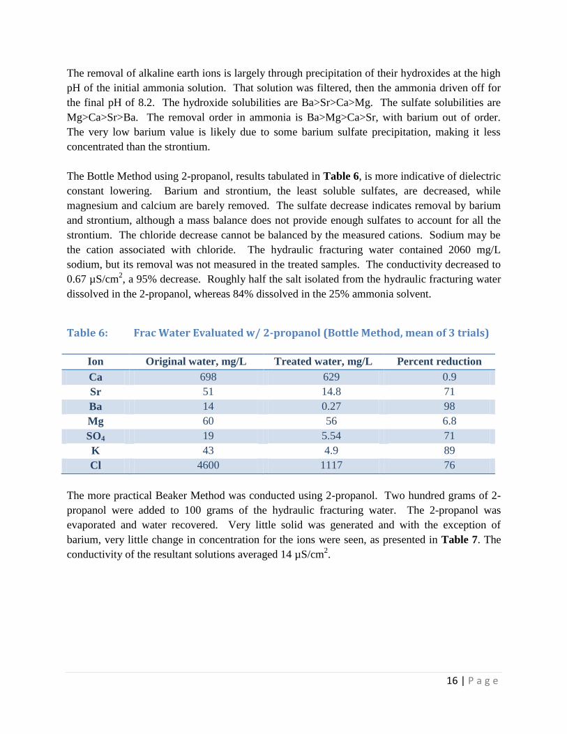
The Bottle Method using 2-propanol, results tabulated in Table 6, is more indicative of dielectric
constant lowering. Barium and strontium, the least soluble sulfates, are decreased, while
magnesium and calcium are barely removed. The sulfate decrease indicates removal by barium
and strontium, although a mass balance does not provide enough sulfates to account for all the
strontium. The chloride decrease cannot be balanced by the measured cations. Sodium may be
the cation associated with chloride. The hydraulic fracturing water contained 2060 mg/L
sodium, but its removal was not measured in the treated samples. The conductivity decreased to
0.67 µS/cm2, a 95% decrease. Roughly half the salt isolated from the hydraulic fracturing water
dissolved in the 2-propanol, whereas 84% dissolved in the 25% ammonia solvent.
Table 6: Frac Water Evaluated w/ 2-propanol (Bottle Method, mean of 3 trials)
Ion Original water, mg/L Treated water, mg/L Percent reduction
Ca 698 629 0.9
Sr 51 14.8 71
Ba 14 0.27 98
Mg 60 56 6.8
SO4 19 5.54 71
K 43 4.9 89
Cl 4600 1117 76
The more practical Beaker Method was conducted using 2-propanol. Two hundred grams of 2-
propanol were added to 100 grams of the hydraulic fracturing water. The 2-propanol was
evaporated and water recovered. Very little solid was generated and with the exception of
barium, very little change in concentration for the ions were seen, as presented in Table 7. The
conductivity of the resultant solutions averaged 14 µS/cm2.

17 | P a g e
Table 7: Frac Water Evaluated w/ 2-propanol (Beaker Method, mean of 3 trials)
Ion Original water, mg/L Treated water, mg/L Percent reduction
Ca 698 801 -15
Sr 51 54.5 -7
Ba 14 1.0 93
Mg 60 69 -14
SO4 19 16.5 13
K 43 41.5 3
Cl 4600 4240 8
The Beaker Method has been shown to successfully remove salts from higher dissolved solids
hydraulic fracturing waters, but this water was too dilute. The intent was to lower TDS to 50,000
mg/L. This water started at 10,000 mg/L TDS. Barium removal was consistent in all cases. The
change in solvent polarity lowered the solubility, which is small even in water, and removed
barium as the sulfate. Other ions were not removed. Some ions showed a negative removal.
The final volume in all three treatments was less than the starting volume, hence some ions
showed higher concentrations.
Laboratory Verification of PDU Laboratory studies consisted of multiple filtration runs, with and without EC pretreatment, with
the objectives to determine an acceptable combination of filter media and evaluate the impact of
EC pretreatment on the filtrate. Actual Marcellus RFW samples were used for all tests.
The PDU consisted of the 2-gpm FilterSure multiple module, multi-media filtration unit as
shown in Figure 4. The unit consisted of five sequential modules containing selected filter
media. As configured here, the five modules are made up of two stacks, three in one stack and
two in the other, all five operating sequentially. If the media are selected correctly, all five
modules will load up with solids at the same rate, minimizing offline time for backwashing the
modules. A rented laboratory-scale EC unit was used to pretreat water samples.

18 | P a g e
Figure 4: Media Testing of PDU for Treating Marcellus RFW
Once analyses were conducted on the raw RFW samples, each sample was divided into three
sub-samples, one to be treated with EC only, one to be treated with the FilterSure filtration
system, and one to be treated by the combination of EC plus FilterSure filtration. All samples
were analyzed for natural salt constituents, TDS, TSS, hardness, pH, and particle size
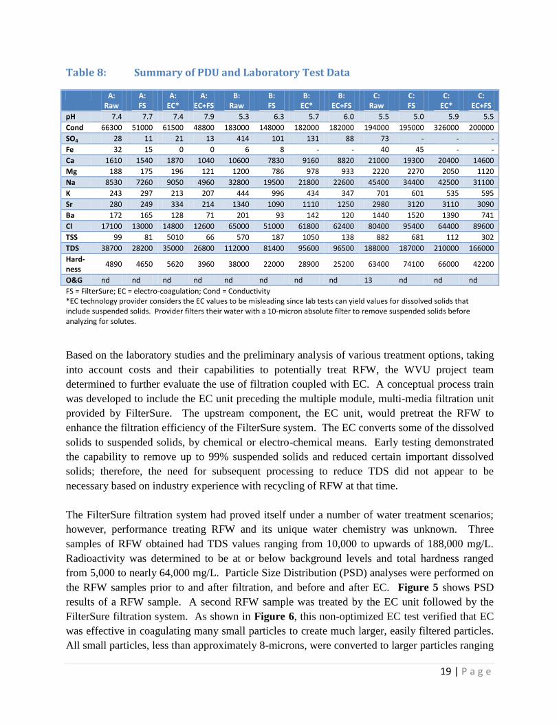
distribution, both before and after each test. Results of tests were summarized in Table 8.
Results indicated significant reductions in divalent ion concentrations and TSS were reduced by
up to 76% with retention of nearly 100% of particles larger than three microns. Therefore, the
process design system proposed by the WVU project team and verified through analyses,
consisting of the EC technology followed by the FilterSure filtration system, showed the
capability to lower water hardness, reduce heavy metals to environmentally safe concentrations,
and lower TDS values of RFW to be ready-for-use for the next hydraulic fracturing operation.
19 | P a g e
Table 8: Summary of PDU and Laboratory Test Data
A: Raw
A: FS
A: EC*
A: EC+FS
B: Raw
B: FS
B: EC*
B: EC+FS
C: Raw
C: FS
C: EC*
C: EC+FS
pH 7.4 7.7 7.4 7.9 5.3 6.3 5.7 6.0 5.5 5.0 5.9 5.5
Cond 66300 51000 61500 48800 183000 148000 182000 182000 194000 195000 326000 200000
SO4 28 11 21 13 414 101 131 88 73 - - -
Fe 32 15 0 0 6 8 - - 40 45 - -
Ca 1610 1540 1870 1040 10600 7830 9160 8820 21000 19300 20400 14600
Mg 188 175 196 121 1200 786 978 933 2220 2270 2050 1120
Na 8530 7260 9050 4960 32800 19500 21800 22600 45400 34400 42500 31100
K 243 297 213 207 444 996 434 347 701 601 535 595
Sr 280 249 334 214 1340 1090 1110 1250 2980 3120 3110 3090
Ba 172 165 128 71 201 93 142 120 1440 1520 1390 741
Cl 17100 13000 14800 12600 65000 51000 61800 62400 80400 95400 64400 89600
TSS 99 81 5010 66 570 187 1050 138 882 681 112 302
TDS 38700 28200 35000 26800 112000 81400 95600 96500 188000 187000 210000 166000
Hard-ness
4890 4650 5620 3960 38000 22000 28900 25200 63400 74100 66000 42200
O&G nd nd nd nd nd nd nd nd 13 nd nd nd
FS = FilterSure; EC = electro-coagulation; Cond = Conductivity *EC technology provider considers the EC values to be misleading since lab tests can yield values for dissolved solids that include suspended solids. Provider filters their water with a 10-micron absolute filter to remove suspended solids before analyzing for solutes.
Based on the laboratory studies and the preliminary analysis of various treatment options, taking
into account costs and their capabilities to potentially treat RFW, the WVU project team
determined to further evaluate the use of filtration coupled with EC. A conceptual process train
was developed to include the EC unit preceding the multiple module, multi-media filtration unit
provided by FilterSure. The upstream component, the EC unit, would pretreat the RFW to
enhance the filtration efficiency of the FilterSure system. The EC converts some of the dissolved
solids to suspended solids, by chemical or electro-chemical means. Early testing demonstrated
the capability to remove up to 99% suspended solids and reduced certain important dissolved
solids; therefore, the need for subsequent processing to reduce TDS did not appear to be
necessary based on industry experience with recycling of RFW at that time.
The FilterSure filtration system had proved itself under a number of water treatment scenarios;
however, performance treating RFW and its unique water chemistry was unknown. Three
samples of RFW obtained had TDS values ranging from 10,000 to upwards of 188,000 mg/L.
Radioactivity was determined to be at or below background levels and total hardness ranged
from 5,000 to nearly 64,000 mg/L. Particle Size Distribution (PSD) analyses were performed on
the RFW samples prior to and after filtration, and before and after EC. Figure 5 shows PSD
results of a RFW sample. A second RFW sample was treated by the EC unit followed by the
FilterSure filtration system. As shown in Figure 6, this non-optimized EC test verified that EC
was effective in coagulating many small particles to create much larger, easily filtered particles.
All small particles, less than approximately 8-microns, were converted to larger particles ranging

20 | P a g e
from about 10- to 200-microns, making them relatively easy targets for removal by the FilterSure
filtration system.
Figure 5: PSD Before and After FilterSure Filtration of a RFW Sample
0
1
2
3
4
5
6
0 1 2 3 4 5 6 7 8
Re
lati
ve P
SD, P
ct
Particle Size, microns
Particle Size Distribution Comparison, Sample #2, Marcellus Shale Before & After FilterSureTM
BEFORE
AFTEROver 40% particulate removal from
1.5 to 3 microns
Complete particulate removal above 3 microns

21 | P a g e
Figure 6: Particle Size in Raw and EC-Treated Marcellus RFW
0
1
2
3
4
5
6
7
8
0.01 0.1 1 10 100 1000
Pa
rtic
le S
ize
Dis
trib
uti
on
s, p
ct
Particle Size, microns (logarithmic Scale)
Particle Size Distribution, Sample #3 & 3EC, Marcellus ShaleBefore and After Electrical Coagulation
PSD of Raw Water, before EC treatment
PSD of Water after EC Treatment

22 | P a g e
Filtration without Pretreatment Members of the WVU project team met with members of the Industry Contact Group
and toured active well development sites in Pennsylvania and West Virginia. The
purpose of these meetings and site visits was to confirm current water management
practices being implemented in the field and determine how this project might impact
industry practices.
From the information obtained during these meetings and site visits, it was clear that
large Marcellus Shale operators were not chemically treating their RFW prior to
recycling. If they were treating the RFW, the treatment choice was 20-micron sized bag
filters. Water treatment options were expected to have minimal operation and
maintenance requirements and consist of a small, modular footprint. The operators
indicated a desire for further dissolved metallic solids reduction and sulfates reduction;
however, the removal of barium and strontium was no longer considered critical. Some of
the producers injected untreated RFW, ignoring ideal design criteria established by the hydraulic
fracturing support companies.
As a result of this industry input, it became clear to the WVU project team, major producers did
not want or need the addition of EC or chemical flocculation prior to filtration as part of their
RFW treatment system for recycling purposes. Although the companies indicated a desire for
heavy metals removal, they were not interested in anything that might slow down or complicate
fracking operations, including large equipment on their “always too small” well sites. Industry
demonstrated their primary needs were high-rate filtration operations, a minimum of 100 gpm
and preferably much higher, while achieving suspended solids removal down to 20 microns. A
reduction in sulfates was also considered important because of its capacity to form scaling
compounds when the RFW would be recycled for new fracking operations. Additionally, the
treatment system would need minimal operator support and maintenance, occupy a small
footprint, and be easily mobilized and de-mobilized from site to site.
At the same time these activities were ongoing, the WVU project team was investigating the
requirements for a full-scale EC unit to pair with the FilterSure system. It was becoming
apparent that the EC unit would be more cumbersome than originally envisioned, require its own
mobile trailer unit and large source of power, and would cost more to obtain and operate; not
entirely insurmountable problems but worth further investigation.
The use of the multi-media FilterSure filtration system without EC pretreatment would provide
better mobility requiring only one mobile trailer unit, lower capital and operating costs, and
flexibility to meet throughput needs while meeting industry water treatment requirements for
recycling RFW. Therefore, the WVU project team concluded:

23 | P a g e
FilterSure’s multiple module, multi-media filtration unit met industry needs and offered a
desirable level of environmental protection, and
EC treatment was not a viable industry option for mobile treatment of Marcellus RFW,
with on-site recycling as the end objective. Rather, EC was more suited for use at a
stationary treatment facility where water would be brought to the facility for treatment.
An EC unit that would be able to adequately handle the throughput needs of industry
would require a much larger footprint and source of power, two characteristics that are
not conducive or available to a Marcellus well site environment.
The WVU project team briefed DOE on the two viable options to move the project forward into
the design, construction and field deployment phase:
1. Construct the EC and FilterSure mobile unit having a combined rated capacity of 30-gpm
with a provision for by-passing the EC unit. This configuration would require two
mobile trailer units, one for the EC unit and its separate power generator and one for all
other components. The 30-gpm size was determined to be the largest-sized EC unit to
keep the footprint and power requirements manageable for on-site applications.
However, industry throughput requirements would not be met, or
2. Construct a mobile unit using only the FilterSure multiple module, multi-media filtration
technology providing a throughput capacity of 120-gpm with the possibility to approach
150-gpm, while meeting minimum RFW treatment requirements. This configuration
would require one mobile trailer unit for all components and power supply would be
provided by a generator packaged with the mobile unit.
After further evaluation, along with input from the DOE, option two was subsequently
approved. The design of the prototype Mobile Treatment Unit (MTU) would consist of two
FilterSure multiple module, multi-media filtration units to provide the throughput capacity and
minimum treatment requirements needed by industry for on-site treatment of RFW.
Opting for filtration without EC or other chemical pretreatment was expected to result in little or
no reduction in dissolved solids. Because RFW typically consist of high concentrations of
various natural salts, the question arose among some Marcellus operators if salt concentrations
could reach a level that would deem the continued use of recycled RFW as part of the make-up
of hydraulic fracturing water detrimental to well production. Analysis showed recycled RFW
could be reused indefinitely. The process of combining fresh water with the saltier RFW
resulted in a predictable but quickly-stabilized build-up of salt concentrations in the hydraulic
fracturing water with successive blending cycles of RFW and fresh water.
For a given development region, the saltiness of water mixtures used for any subsequent
hydraulic fracturing operation should quickly reach a maximum. This maximum value is a

24 | P a g e
function of the amount of RFW available for blending and its initial salt concentrations. This
stabilization, or maximum salt concentration, occurs by the 3rd
repeat cycle as shown in Figure 7
and Table 9. The salt concentration is approximately the same for the 4th
hydraulic fracturing
cycle as for the 3rd
cycle, and will remain constant for all subsequent hydraulic fracturing
operations, assuming no effective changes in significant variables from well to well.
Figure 7: Predicting Stabilized Frac Water TDS when Recycling RFW
Table 9 provides a snapshot of the spreadsheet developed to calculate major ions and TDS
concentrations of RFW recycled for subsequent fracturing operations. These values are based on
the percent RFW recycled and blended with make-up water and initial water quality
characteristics of both the make-up water and RFW. The user of Table 9 inputs the percent
recycle rate along with initial water quality characteristics for the make-up water and RFW.
Results of chemical analyses of the make-up water source and the RFW being used are entered
into the spreadsheet. Values for TDS and the various ions listed are then calculated for each
repeat cycle. For example, if the typical amount of RFW is 20% of the total amount of frac
water injected, and the TDS of the RFW is 108,665 mg/L, the stabilized salt concentration, TDS,
for future hydraulic fracturing jobs will be approximately 27,366 mg/L. Levels of the ions
barium (Ba), strontium (Sr) and sulfate (SO4) found in the RFW, may be limiting factors for how
much RFW can be blended with fresh make-up water for subsequent fracturing operations.

25 | P a g e
Table 9: RFW Dilution Model
Insert date in yellow cells only *From BJ Services FR and SI (Scaltrol 720)
Phase II:
Mobile Treatment Unit Design, Construction and Operations With approval to move to the design and construction phase, two 60-gpm FilterSure commercial
filters were selected for installation in a standard shipping container 40 feet long by 8 feet wide
by 8 feet in height, mounted on a mobile chassis. Dual filter system controls provide automatic
operation, maintenance operation, and monitoring of both filtration units. The system functions
are controlled by a programmable logic controller (PLC) located in the control panel shown in
Figure 8. The PLC interfaces with an operator interface Touchscreen (also referred to as an
HMI – human machine interface), remote sensors and system devices. The HMI monitors and
controls normal operation; system set-up such as timing, backwash settings and alarm settings;
status and alarm conditions; and manual maintenance control. An operations manual along with
instructions, drawings and schematics were placed inside the MTU for operator reference.
Designed to process up to 5,000 barrels/day, the mobile treatment unit (MTU), Figure 8, was
customized for well-site applications providing a small footprint with an external generator for
power (50 kVA), easy movement between well pads, and quick set up for subsequent hydraulic
fracturing activities. Once set up at a well pad site, the MTU will operate automatically
requiring routine maintenance between fracturing treatments.
recycle
rate RFW
20% RFW makeup Maximum* 1 2 3 4 5 6 7 8 9 10
TDS 108,665 200 50,000 26,272 27,147 27,322 27,357 27,364 27,366 27,366 27,366 27,366 27,366
Hardness 28,200 50 26,000 6,816 7,043 7,089 7,098 7,100 7,100 7,100 7,100 7,100 7,100
HCO3 100 20 300 43 45 45 45 45 45 45 45 45 45
SO4 50 60 50 70 72 72 72 72 72 72 72 72 72
Cl 45,000 10 45,000 10,810 11,170 11,242 11,256 11,259 11,260 11,260 11,260 11,260 11,260
Na 50,000 10 36,000 12,010 12,410 12,490 12,506 12,509 12,510 12,510 12,510 12,510 12,510
Ca 8,000 20 8,000 1,939 2,004 2,017 2,019 2,020 2,020 2,020 2,020 2,020 2,020
Mg 2,000 10 1,200 490 506 509 510 510 510 510 510 510 510
K 500 15 1,000 134 139 140 140 140 140 140 140 140 140
Fe 5 1 10 2 2 2 2 2 2 2 2 2 2
Ba 800 - 10 192 198 200 200 200 200 200 200 200 200
Sr 2,200 - 10 528 546 549 550 550 550 550 550 550 550
Mn 10 1 10 3 3 3 3 3 3 3 3 3 3
cycleinitial
RFW dilution model: all ions
26 | P a g e
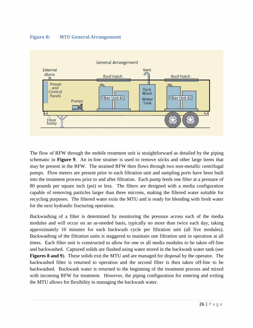
Figure 8: MTU General Arrangement
The flow of RFW through the mobile treatment unit is straightforward as detailed by the piping
schematic in Figure 9. An in-line strainer is used to remove sticks and other large items that
may be present in the RFW. The strained RFW then flows through two non-metallic centrifugal
pumps. Flow meters are present prior to each filtration unit and sampling ports have been built
into the treatment process prior to and after filtration. Each pump feeds one filter at a pressure of
80 pounds per square inch (psi) or less. The filters are designed with a media configuration
capable of removing particles larger than three microns, making the filtered water suitable for
recycling purposes. The filtered water exits the MTU and is ready for blending with fresh water
for the next hydraulic fracturing operation.
Backwashing of a filter is determined by monitoring the pressure across each of the media
modules and will occur on an as-needed basis, typically no more than twice each day, taking
approximately 10 minutes for each backwash cycle per filtration unit (all five modules).
Backwashing of the filtration units is staggered to maintain one filtration unit in operation at all
times. Each filter unit is constructed to allow for one or all media modules to be taken off-line
and backwashed. Captured solids are flushed using water stored in the backwash water tank (see
Figures 8 and 9). These solids exit the MTU and are managed for disposal by the operator. The
backwashed filter is returned to operation and the second filter is then taken off-line to be
backwashed. Backwash water is returned to the beginning of the treatment process and mixed
with incoming RFW for treatment. However, the piping configuration for entering and exiting
the MTU allows for flexibility in managing the backwash water.

27 | P a g e
Figure 9: Mobile Treatment Unit Piping Schematic Diagram
Construction of the MTU began in the spring of 2011 and proceeded without major issues.
Figures 10 and Figure 11, exterior and interior photographs respectively, show progress near
the end of the construction phase.
Figure 10: Finished Exterior View of MTU

28 | P a g e
Figure 11: Completed Interior View of MTU
Selection of the final filter media to be used in the MTU was determined by additional laboratory
testing using the FilterSure 2-gpm PDU. Nearly 100 barrels of Marcellus shale RFW were
provided by a local operator for the additional laboratory tests. The RFW contained solids
ranging in size from less than 3 microns to over 100 microns. Under high rate conditions, the
PDU operating at rates up to 6-gpm, the media selected for the PDU removed particles larger
than 3 microns as shown in Figure 12.

29 | P a g e
Figure 12: Particle Size Distribution Results
Over the course of the laboratory testing phase, the 2-gpm FilterSure PDU consistently removed
solids and reduced various ions such as chlorides, sulfates, sodium and barium as summarized in
Table 10. Chemically, the filtered RFW met the current industry standards for continued use as
frac water when blended with fresh water. Therefore, the media and sequence tested in the 2-
gpm PDU was duplicated for both FilterSure filtration units installed in the MTU. Designed to
process 5,000 barrels/day, the MTU was prepared for field deployment and real-time testing.

30 | P a g e
Table 10: Filtration Results of Filtered RFW Samples
A:
Raw A: FS
B: Raw
B: FS
C: Raw
C: FS
D: Raw
D: FS
Average Change,
%
Cl 17100 13000 65000 51000 80400 95400 150000 106667 -14
SO4 28 11 414 101 73 - 0 0 -69
Fe 32 15 6 8 40 45 64 66 0
Ca 1610 1540 10600 7830 21000 19300 21000 22183 -8
Mg 188 175 1200 786 2220 2270 2120 2187 -9
Na 8530 7260 32800 19500 45400 34400 42780 42780 20
K 243 297 444 996 701 601 1810 1875 34
Sr 280 249 1340 1090 2980 3120 5060 5267 -5
Ba 172 165 201 93 1440 1520 2290 2397 -12
pH 7.4 7.7 5.3 6.3 5.5 5.0 - - 4
Cond 66300 51000 183000 148000 194000 195000 197000 197167 -10
TSS 99 81 570 187 882 681 484 313 -36
TDS 38700 28200 11200 81400 188000 187000 187000 168667 -16
Hardness 4890 4650 38000 22000 63400 74100 65900 69300 -6
O&G nd nd nd nd 13 nd nd nd
Charge Balance, %diff
0 14 13 6 38 3 25 11 14
nd = not detected
Field Trials Two field trials were completed, both under a lease agreement with Chesapeake Energy
(Chesapeake). The first location was a Utica Shale site in Carrollton, Ohio. The second was a
Marcellus Shale site located near Wheeling, West Virginia.
Site 1: Utica Shale Site FilterSure moved the MTU from the manufacturing location to the first drilling site located in
Carroll County, Ohio. Storage containers were available on site to hold water prior to filtration
and to provide storage after treatment prior to blending with fresh water for the next fracturing
operation. At this particular site, storage containers were the preferred method of water storage

31 | P a g e
instead of impoundments. Chesapeake positioned the MTU where untreated water from the
yellow tanks shown in Figure 13 could be easily connected to the MTU. The filtered water was
transferred to empty storage tanks located to the right of the MTU (not shown in this
photograph). Filtered RFW was blended with fresh water and used in subsequent hydraulic
fracturing operations.
Figure 13: On Location at Utica Shale Site in Ohio
The MTU was on site in Carrollton, Ohio for eleven days, of which the unit was in “operational
mode” nine days. Once the MTU was positioned by Chesapeake on the well pad, it was
connected to the generator for power and connections were made to the water storage tanks
supplying water to be treated and collecting water after treatment. Commands for the PLC were
updated and initial testing of the system was conducted prior to start-up to ensure the alarm
system and automatic shutdown mode executed properly. Emergency and safety systems were in
place and worked according to the operations manual.
The Ohio site consisted of one well with 15 fracking stages. The company on site overseeing the
fracturing operations performed two fracking stages per day. Water was collected from various
Chesapeake development wells and trucked to the Ohio site to be treated by the MTU prior to
blending with fresh water. These liquids ranged in quality from rain water to highly saline water.
Some of the liquids also contained oils and polymers collected from recently fracked oil wells.
In addition, as a part of its water management plan, Chesapeake routinely removed rain water
trapped behind an extensive dyke system constructed for secondary containment of water that
may leak from storage operations. This water was pumped into the “raw” water storage tanks to
be treated by the MTU for recycling as well (yellow tanks shown in Figure 13). The quality of

32 | P a g e
the water being processed through the MTU was unpredictable, it was a highly variable liquid
that sometimes contained a significant quantity of oil and/or polymer, as seen in Figure 14.
Although the oil and polymer mixture was processed (removed) by the MTU, it was at a cost of
higher pressure and a reduced throughput rate.
Figure 14: Oil/Polymer Mixture Treated by MTU
At the Carrollton, Ohio site, the MTU processed water for fracking at a rate of 122 gallons/min
(about 4,000 barrels/day). Pressure across the filter modules remained relatively low, averaging
around 30 psi. Water leaving the MTU was clear in appearance and influent and effluent
samples were collected and processed for laboratory analysis. However, these samples were not
considered to adequately represent the entire 200,000 gallons of water treated at the Ohio site
because of the variation in water brought in to the site. The water chemistry was fairly consistent
with other hydraulic fracturing water samples taken during this project for analysis. Also,
filtration did not significantly change the water chemistry of the major ionic species.
The MTU is designed for automatic or manual operations. However, to meet Chesapeake’s site
safety guidelines, an MTU operator was on site while the unit was in operation. The panel
mounted on the wall shown in the background of Figure 15, controls the MTU operations and
records all operational conditions. Figure 16 is a photograph of the Touchscreen or HMI
showing Filter 1 operating at 41 gpm and Filter 2 operating at 43 gpm; thus, the total flow
through the MTU at the time of the photograph was 84 gpm, or 2,880 barrels/day (bpd).

33 | P a g e
Figure 15: MTU Control Panel
Figure 16: Control Panel Close-Up View
A pressure gauge records the pressure drop from the inlet to the outlet of each filter, Figure 17.
At the time of this photograph, Figure 17, the pressure drop across Filter 1 was 64 psig and
across Filter 2 was 68 psig. The pressure drop across each module monitors the performance of
the media contained in each filtration cell (build-up of solids removed from the water), is used to
adjust backwash cycles as needed and to modify selection of media for future applications based
on the quality of water being treated by the MTU.

34 | P a g e
Figure 17: Pressure Drop Measurements of MTU in Operation
Initial operations showed a gradual decline in the throughput (filtration) rate and a gradual
increase in pressure as the media collected solids and the system stabilized. Figure 18 plots the
throughput rates and inlet pressures for the first six days of operation. On day one, the MTU
began processing water at a throughput rate of 122 gpm (4,183 bpd) and stabilized at a
throughput rate of 104 gpm (3,566 bpd) by day five. Over this period, the pressure increased
from an initial pressure of 30 psig to 53 psig.

35 | P a g e
Figure 18: Day 1 through Day 6 Filtration Rates and Pressures
During day six of operations, processed water containing a high concentration of an oil and
polymer mixture, as shown previously in Figure 14, was received and processed through the
MTU. The impact of the heavy solids and oil/polymer loading on pressure and filtration rate is
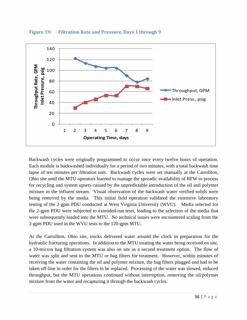
reflected in Figure 19. Pressure increased 32%, from 53 psig to 70 psig. At the same time, the
rate decreased 25%, from 104 gpm to 78 gpm. Most of the oil and polymer mixture was
captured during the normal programmed backwash cycles; however, some of this mixture was
retained on the filter media. By day eight, the backwash cycles had successfully removed the
remaining mixture of oil and polymer with trapped solids on the filter media, increasing
throughput from 78 gpm to 84 gpm while simultaneously lowering the pressure from 70 psig to
66 psig. The backwash cleaning process returned operating conditions to a 100 gpm throughput
rate at an inlet pressure of approximately 45 psig by the end of day nine.
36 | P a g e
Figure 19: Filtration Rate and Pressure, Days 1 through 9
Backwash cycles were originally programmed to occur once every twelve hours of operation.
Each module is backwashed individually for a period of two minutes, with a total backwash time
lapse of ten minutes per filtration unit. Backwash cycles were set manually at the Carrollton,
Ohio site until the MTU operators learned to manage the sporadic availability of RFW to process
for recycling and system upsets caused by the unpredictable introduction of the oil and polymer
mixture in the influent stream. Visual observation of the backwash water verified solids were
being removed by the media. This initial field operation validated the extensive laboratory
testing of the 2-gpm PDU conducted at West Virginia University (WVU). Media selected for
the 2-gpm PDU were subjected to extended-run tests, leading to the selection of the media that
were subsequently loaded into the MTU. No technical issues were encountered scaling from the
2-gpm PDU used in the WVU tests to the 120-gpm MTU.
At the Carrollton, Ohio site, trucks delivered water around the clock in preparation for the
hydraulic fracturing operations. In addition to the MTU treating the water being received on site,
a 10-micron bag filtration system was also on site as a second treatment option. The flow of
water was split and sent to the MTU or bag filters for treatment. However, within minutes of
receiving the water containing the oil and polymer mixture, the bag filters plugged and had to be
taken off-line in order for the filters to be replaced. Processing of the water was slowed, reduced
throughput, but the MTU operations continued without interruption, removing the oil/polymer
mixture from the water and recapturing it through the backwash cycles.
0
20
40
60
80
100
120
140
1 2 3 4 5 6 7 8 9
Thro
ughp
ut R
ate,
GPM
Inle
t Pre
ssur
e, p
sig
Operating Time, days
Throughput, GPM
Inlet Press., psig

37 | P a g e
The MTU utilizing the FilterSure technology proved to be highly versatile responding to “upset”
conditions. This response capability will continue to improve with future plans to introduce an
additional media module that will capture oil-based solutions before passing through to the other
media modules of the filtration unit.
Lessons Learned from Site 1 Laboratory tests using a consistent quality of produced water cannot match the variable quality
and quantity of the water delivered to a site by hundreds of trucks supplying water from a wide
variety of sources. Even so, laboratory tests conducted at WVU utilizing the 2-gpm PDU for
processing various RFW samples resulted in the selection of five media types that treated the
water for recycling purposes.
Media for the MTU needs to be more robust in its capability to capture oil and/or polymers
before this mixture enters the lower modules of the filter. In the future, an oil-loving media will
be used to process the influent before it enters the MTU or placed in the first of the five filtration
modules used in the FilterSure technology. This approach will protect the lower modules from
fouling, and greatly reduce the time to backwash the unit to restore overall throughput at a
reasonable inlet pressure.
Site 2: Marcellus Shale Site Upon completion of water treatment operations at the Carrollton, Ohio site, Chesapeake
relocated the MTU to a location near Wheeling, West Virginia. Figure 20 shows the
arrangement of water storage tanks and the MTU, the MTU is located in the left top corner of the
photograph, on the well pad. RFW for filtration was trucked onto the site and stored in the tanks
in the foreground as shown in Figure 20. From the storage tanks, the water was processed
through the MTU. The filtered water was stored in the yellow tanks positioned to the right of the
FilterSure unit and ready for blending with fresh water supplies prior to the hydraulic fracturing
operations.

38 | P a g e
Figure 20: Marcellus Shale Site, West Virginia
Upon arrival at the new site, the Dytko Site, in West Virginia, a series of system checks were
performed and the MTU was prepared to begin operations. The MTU supported a nine-stage
fracking operation, operating at an average filtration rate of 104 gpm and at a pressure of 52 psig
to treat RFW prior to blending with fresh water supplies. Within four days, all stored RFW,
approximately 147,000 gallons, was filtered and consumed the storage capacity provided for
processed (treated) water ready for recycling. Once fracturing operations began, the MTU was
taken off-line during the actual fracture operations while water was withdrawn from the filtered
water tanks and blended with fresh water for use in fracturing. Filtration resumed after each
fracture stage.
Figure 21 details the fracturing stages and the amount of RFW processed by the MTU. MTU
operations were able to keep up with the ongoing demands to support the eight hydraulic
fracturing stages. One additional fracture was supported but not shown in Figure 21 before
fracture operations were completed. Nearly 288,000 gallons of water was processed by the MTU
at the Dytko Site.

39 | P a g e
Figure 21: Water Treated for Fracturing Stages
Frequent rate and pressure data were taken during the fracking operations. Figure 22
summarizes this data showing stable throughput (filtration) rates and pressures. Filtration rates
averaged 104 gpm at an average filter inlet pressure of 52 psig. There were no major deviations
in the rate and pressure data, reflecting relatively clean water was being processed for recycle
purposes.

40 | P a g e
Figure 22: Rate and Pressure Data during Water Treatment
As mentioned previously, during active fracturing, the MTU was off-line. While off-line,
captured solids were removed by backwashing each filter individually. Ten backwash cycles
were completed using an average volume of 400 gallons per cycle. Backwash volume totaled
4,000 gallons. RFW processed for recycle totaled 288,000 gallons for blending with fresh water.
Of the total volume of water sent through the MTU unit, 98.6% was recycled with 1.4% returned
for disposal.
MTU operators learned from the Ohio site operations that water collected for physical and
chemical analyses need to reflect a broad range of water influent and effluent. Accordingly,
MTU operators collected composite samples over a period of time while at the Dytko Site.
These composite samples were submitted for particle size distribution (PSD) to the Civil
Engineering Department at WVU and for chemical analysis by REIC Laboratories located in
Beaver, West Virginia.
Concentration of particles in the collected water was unexpected. All prior testing of Marcellus
Shale RFW had particle size distributions ranging from near-zero to over 100 microns in size.
However, both the influent and effluent water collected from the West Virginia site had particles
that ranged from near-zero to less than three microns. Concentration of the influent and effluent
particles is shown in Figure 23.

41 | P a g e
Figure 23: Influent and Effluent PSD from West Virginia RFW
It is clear from Figure 23, particle size data the MTU did indeed remove particles that were as
small as 0.5 microns in diameter. This is remarkable removal efficiency and is shown
graphically as the difference between the blue (influent) and the red (effluent) curves of Figure
23. This reduction in volume shows up as a reduction in Total Suspended Solids (TSS) in the
water chemistry analysis prepared by REIC laboratories.
Water chemistry analysis results are presented in Table 11. These results independently verify
the MTU removed 32% of the suspended solids. Specifically, the TSS fell from 360 mg/L to
244 mg/L, a reduction of 116 mg/L. Previous controlled laboratory testing using Marcellus
Shale RFW samples had an average TSS influent of 517 mg/L and an average effluent of 316
mg/L; a reduction of 39%. The laboratory and the current TSS reductions from the West
Virginia site were therefore similar.
TDS readings were very low, with the influent and effluent water at about 22,000 mg/L. Prior
Marcellus Shale RFW tested at WVU averaged 113,000 mg/L. Looking at the water chemistry
of the RFW water received at the Dytko Site may have consisted mostly of early flowback water

42 | P a g e
(water returning back up hole in advance of gas production) and previously blended with fresh
water. Comparing water quality parameters of the MTU influent and effluent to the values
determined to be critical by the Industry Contact Group detailed in Table 1, both met the criteria
with the exception of iron, barium and strontium.
Table 11: Marcellus Shale Site Water Chemistry
Avg Influent
mg/L
Avg Effluent
mg/L
Avg Change
mg/L
Avg Change,
%
Cl 15400 12300 -3100 -20
SO4 24 24 0 0
TDS 21300 22600 1300 6
TSS 360 244 -116 -32
Ba 35 37 2 8
Ca 2660 2740 80 3
Fe 17 18 1 2
Mg 293 308 15 5
K 117 127 10 9
Na 5620 5830 210 4
Sr 360 364 4 1
Lessons Learned Water collected for testing from the West Virginia site had very fine particles (less than 3
microns) and low TDS values (average of 21,300 mg/L). Marcellus Shale water samples tested
at the WVU laboratory during Phase I of the project as well as additional testing conducted at the
beginning of Phase II to finalize filter media selections had significantly larger particles (over
100 microns) and a much higher TDS (average of 113,000 mg/L). Although RFW treatment
results met industry requirements for recycling, additional analyses of the influent and effluent
water stream may have been able to clarify the initial water quality results of the raw RFW
received at the Dytko Site.
Project Summary Shale gas production depends on the creation of permeability within an otherwise nearly
impermeable rock formation. Horizontal drilling and hydraulic fracturing have been applied to
produce natural gas from tight shale formations previously thought to be non-obtainable.

43 | P a g e
Hydraulic fracturing (fracking) uses large volumes of water to create numerous channels within
the shale formation. Sand, pumped with the water, props open the hydraulic fractures, thus
providing multiple, permeable flow paths for the natural gas. However, the withdrawal of local
water resources for fracking and the returned frac water (RFW) create two significant
environmental issues that must be dealt with. The search for a way to mitigate the situation and
improve the overall efficiency of shale gas production suggested treatment of the RFW that
would allow for the water to be recycled and reused for successive fracking operations. This
would reduce the demand on local water resources and provide an economical and
environmentally friendly way to manage the RFW. Project objectives were to identify the
composition of RFW, define industry standards for the quality of make-up water used for
fracking, and develop a technique to treat RFW for blending recycling.
Several samples of Marcellus Shale RFW were obtained and analyzed throughout the course of
this project. Table 12 provides an overview of various chemical parameters acknowledging
RFW is best characterized by providing a range of values for each. Differences in parameter
values from sample to sample may be the result of 1) when the sample was taken during flow
back, 2) the water quality characteristics of the original frac water because sources of make-up
water vary, 3) chemical additives blended with the frac water since each company has their own
mixture which is often proprietary, and/or 4) differences throughout the formation itself.
Table 12: RFW Chemical Analyses
Raw RFW Samples Industry Guidelines
TDS 9730 – 188000 50000
Hardness 923 – 63400 26000
SO4 nd – 414 50
Cl 4600 – 80400 45000
Na 2060 – 45400 36000
Ca 319 – 21000 8000
Mg 31 – 2200 1200
K nd – 701 1000
Fe 6 – 59 10
Ba 0 – 1640 10
Sr <1 – 3559 10 *Treated by FilterSure multiple module multi-media filtration system
Industry standard for acceptable RFW water quality standards continue to evolve. When
contacted, the consensus from the Industry Contact Group concerning acceptable water quality
for recycled RFW indicated TSS values below 20 microns along with a range of other
parameters also provided in Table 12 above. Concerns with sediment accumulations in the
pores and well bore were reflected by industry’s TSS requirements. The other chemical

44 | P a g e
parameters were thought to interfere with the performance of the frac water and/or potentially
increase scale formation. Dissolved solids removal was important but not critical because most
of the industry criteria could be achieved with blending of the treated RFW and fresh water.
Based on industry input and preliminary analyses of RFW samples, the WVU project team
proceeded to determine an efficient and effective method to treat RFW for recycling purposes.
Filtration was determined to be a necessary treatment step, possibly coupled with a process for
removing salts. Various processes were examined such as reverse osmosis (RO), nanofiltration
and electro-coagulation (EC). Upon review of costs and operational requirements of the various
processes, further evaluation of EC was recommended.
Several RFW samples were obtained from various Industry Contact Group members. Samples
were treated by a small-scale EC unit and a 2-gpm process demonstration unit (PDU) of the
FilterSure multiple module, multi-media filtration system. Laboratory analyses showed that
pretreatment of the water by EC prior to the FilterSure PDU filtration system was not required to
meet the water quality criteria of industry at that time for recycling RFW. These results led to
the design and construction of a mobile treatment unit (MTU) utilizing the FilterSure multiple
module, muti-media technology to field test.
A fully-automated MTU was designed, constructed and delivered to a Utica Shale site in
Carrollton, Ohio during September 2011. The MTU consisted of two FilterSure filtration units
each capable of operating between 60 and 70 gpm. Operations at the Utica Shale site were
followed by operations at a Marcellus Shale site location near Wheeling, West Virginia.
Capacity of the MTU was adequate to support field operations at both sites. The mobile unit was
able to keep up with on-going fracking operations and produce a quality effluent for blending
with fresh water and used for subsequent fracturing operations thus reducing the overall quantity
of fresh water needed for fracking operations and providing a cost-effective, environmentally-
sound alternative for managing RFW. Over 600,000 gallons of water were treated at the two
locations with 98.6% of the water being recycled. The remaining 1.4% was used to backwash
the filtration units and then disposed of properly. Suspended solids were reduced by one-third,
particles as small as 0.5 microns were removed, and reduction in some divalent ion
concentrations were observed during field testing. The MTU was able to handle water
containing a highly-viscous oil and polymer mixture that was part of the RFW to be treated at the
Utica Shale site in Ohio. Overall, the MTU proved to be highly capable of responding to “upset”
conditions and treating RFW with widely variable concentrations of various chemical water
quality parameters.
45 | P a g e
Acronyms, Abbreviations and Units of Measurement
avg average
Ba Barium
bpd barrels per day, barrels/day
Ca Calcium
Cl Chloride
cndctvty conductivity
DOE Department of Energy
EC Electro-coagulation
ECFS Electro-coagulation and FilterSure
Fe Iron
FOA Funding Opportunity Announcement
gm gram
gpm gallons per minute
HMI Human Interface Machine, Touchscreen
K Potassium
KCl Potassium Chloride
K2SO4 Potassium Sulfate
kVA kilovolt ampere
Mg Magnesium
mg/L milligrams per liter
mL milliliters
MTU Mobile Treatment Unit
Na Sodium
NaCl Sodium Chloride
NETL National Energy Technology Laboratory
O&G Oil and Grease

46 | P a g e
Pct Rtn percent (%) return
PDU Process Demonstration Unit
PSD Particle Size Distribution
psi pounds per square inch
psig pounds per square inch gauge
RFW Return Frac Water
RO Reverse Osmosis
SO4-2
Sulfate
Sr Strontium
TDS Total Dissolved Solids
TSS Total Suspended Solids
WVU West Virginia University
w/ with
w/w wet weight
µM micro-meter
µS/cm micro-siemens per centimeter
µS/cm2 micro-siemens per square centimeter