Zelio Logic and Altivar Automatyka przemyslowa...Zelio OsiSwitch Phaseo Tesys_EN.doc - 08-2005...
24
Aug_2005 Zelio and OsiSwitch Phaseo and TeSys System User Guide [source code] 33003495.02
Transcript of Zelio Logic and Altivar Automatyka przemyslowa...Zelio OsiSwitch Phaseo Tesys_EN.doc - 08-2005...

Aug_2005
Zelio and OsiSwitch Phaseo and TeSys
System User Guide [source code]
3300
3495
.02

Zelio OsiSwitch Phaseo Tesys_EN.doc - 08-2005
Schneider Electric
2
Contents Typical Applications ..................................................................................................................4 System ........................................................................................................................................5
Architecture.............................................................................................................................5 Installation...............................................................................................................................7
Hardware.............................................................................................................................................................9 Software ............................................................................................................................................................12 Communication .................................................................................................................................................12
Implementation .....................................................................................................................13 HMI ....................................................................................................................................................................14 PLC....................................................................................................................................................................14 Data Exchange..................................................................................................................................................17 Devices..............................................................................................................................................................17
Appendix...................................................................................................................................18 Detailed Component List.......................................................................................................18 Component Protection Classes ............................................................................................19 Component Features ............................................................................................................20
Contact......................................................................................................................................24
Introduction This document is intended to provide a quick introduction to the described System.
It is not intended to replace any specific product documentation. On the contrary, it offers additional information to the product documentation, for installing, configuring and starting up the system. A detailed functional description or the specification for a specific user application is not part of this document. Nevertheless, the document outlines some typical applications where the system might be implemented.

Zelio OsiSwitch Phaseo Tesys_EN.doc - 08-2005
Schneider Electric
3
Abbreviations
Word/expression Explanation PLC Programmable Logic Controller HMI Human Machine Interface PC Personal Computer AC Alternating Current DC Direct Current PSU Power Supply Unit I/O Input/Output CB Isolating switch or motor protection EMERGENCY STOP EMERGENCY STOP switch Zelio Name of a Schneider PLC (controller) Phaseo Name of a Schneider range of SPSU power supply units TeSys U Name of a Schneider compact motor starter combination
Application Source Code
Introduction Examples of the source code and wiring diagrams used to attain the system function as described in this document can be downloaded from our „Village“ website under this link.

Typical Applications
Introduction The following chapter describes some typical applications or partial applications for this
system, which are used in the following market segments: Industry • Small automated machines or plant components • Remote automation systems used to supplement large and medium-sized machines Infrastructure • Access control • Monitoring and separation of zones • Management of heating and air conditioning systems
Application Description Example Gas and filling stations This application facilitates the pumping
of fuel and oils (e.g., natural gas, diesel, fuel oil, etc.) for the refueling of vehicles. The volumetric flow rate or pump delivery rate is determined on the basis of a fixed pump speed and cannot be changed.
Access control, building services engineering, service and maintenance workshops
This application enables roller shutters or segmented roller shutters to be opened and closed/can be used to secure access to separate zones or buildings. Multiple operation and control options are possible in conjunction with a huge range of control elements (e.g., push-button control, pull switches, motion detectors, induction loops), plus crush protection.
Stair lift This application enables a stair lift to be
operated.
Zelio OsiSwitch Phaseo Tesys_EN.doc - 08-2005
Schneider Electric
4

System
Introduction The System chapter describes the quantity, architecture, components, and dimensions
of the devices and parts used.
Architecture
Overview The system consists of a “low-end” PLC with push-buttons for controlling a shutter.
Within this combination, there is scope for an optional rapid shutdown function. The final upper and lower positions of the shutter are detected by roller limit switches. The shutter movement is controlled via a push-button control – the corresponding signal stati are displayed by means of illuminated buttons and a compact signal station. This configuration does not include a bus system. For the purpose of processing additional (optional) signals, the PLC has a number of unallocated inputs and outputs.
Layout
Zelio OsiSwitch Phaseo Tesys_EN.doc - 08-2005
Schneider Electric
5

Zelio OsiSwitch Phaseo Tesys_EN.doc - 08-2005
Schneider Electric
6
Components Hardware:
• Vario VCF master switch • motor starter GV2ME07 and reversing contactors LC1D09BD • As an alternative to motor circuit breaker and contactors: Tesys U • XALK locking-type emergency stop switch with rotary unlocking • Phaseo ABL7 power supply unit • ZELIO compact PLC • XB5 push-buttons and indicator lamps, from the Harmony Style 5 range of push-
buttons • XVBL compact signaling column • XCK OsiSwitch roller limit switches • Standard AC (brake) motor • Software: • ZelioSoft Version 2.0
Degree of protection
Not all of the components used within this configuration have been designed to withstand the full range of environmental conditions in the field. These components will therefore require additional protection and are only suitable for installation in a control cubicle. For information about which components are suitable for direct installation on site, please refer to the list provided in the appendix (column headed “In the field, on site”, which also gives the relevant IP protection class).
Supply voltage 3x400 V AC ± 20% (50/60 Hz) Total supply output Total output: approx. 0.9 kW Motor output ≤ 0.75 kW Motor brake Max. 200 W (L+N) or 1A at 24VDC Connector cross-section 5x 1.5mm² (L1, L2, L3, N, PE)
Design data
Safety category Cat. 1
Safety notice In this application example, Category 1 (according to EN 954-1) has been selected for
the purpose of ensuring safety. The issue of which safety or control category is to be adopted will be determined by the system’s design and the overall extent to which this system represents a hazard to people and machinery.
Size/ Dimensions
The compact dimensions of the devices used, e.g., the PLC and PSU, means that the components can be installed inside a control cubicle with the following approximate external dimensions: 300 x 300 x 210 mm (WxHxD). Moreover, the display elements used to indicate a “group error”, “controller on” and “no protection” can be built into the door of the control cubicle along with the system master switch and emergency stop master switch.

Installation
Introduction This chapter describes the steps required to install the hardware and set up the software
so that the application task concerned can be achieved.
Layout
Note The configuration used for this application is based on the example of a rolling shutter
for a large industrial building. The components and I/O points listed below represent a cross-section of the components and signals that are absolutely essential for control and display purposes and a number of optional inputs and outputs, which can be used in conjunction with most typical applications (e.g., induction loops/pull switches). This SMD does not claim to be comprehensive and does not absolve users of their duty to check the safety requirements of their equipment and to ensure compliance with the relevant national or international rules and regulations in this respect. Safety Category 1, which is suggested here as one possible option, is not necessarily required/not necessarily adequate for every application, as a risk analysis must be produced and verified for each system (in accordance with national and/or international standards and regulations).
Zelio OsiSwitch Phaseo Tesys_EN.doc - 08-2005
Schneider Electric
7

Zelio OsiSwitch Phaseo Tesys_EN.doc - 08-2005
Schneider Electric
8
Zelio PLC inputs Description PLC wiring DC I1 DC I2 DC I3 DC I4 DC I5 DC I6 DC IB Options: DC IC DC ID DC IE DC IF DC IG
Up button Down button Stop button Upper limit switch Lower limit switch Motor circuit breaker External pull switch Crush protection Protection active Chain tightener/torque arm Motion detector/induction loop Spare
Zelio PLC outputs Class Description Q1-Q8
Q1 Q2 Q3 Q4 Q5 Q6 Q7 Q8
Class 1 Class 2 Class 2 Class 2 Class 2 Class 2 Class 2 Class 2 Class 2
+24 V DC power supply contactor control, up contactor control, down Display, “up” is currently active (illuminated button) Display, “down” is currently active (illuminated button) Group error Warning signal (motion in progress) Spare Display, controller on
Zelio 24 V supply Description +
- 24 V DC power supply 0 V DC reference voltage

Hardware
General • Although the motor circuit breaker together with reversing contactor circuit
components (or alternatively TeSys U), Zelio PLC, fuses and power supply can all be mounted on top-hat rails, they can also be installed individually.
• For the purpose of installing the top-hat rails, use standard M5x16 countersunk head screws and washers or blind rivets.
• The master switch, emergency stop button housing and push-button housing are designed for backplane assembly.
• There are two options available for mounting the illuminated buttons: • 22 mm hole in the front door of the control cubicle (emergency stop, controller on) • XALD push-button housing for illuminated buttons located away from control cubicle
for remote operation of the machine (up, down, stop buttons plus built-in displays) • 400 V AC wiring running between the master switch, TeSys U (or alternatively,
motor circuit breaker and reversing contactor circuit), and shutdown relay (via safety circuit) to the motor, with some terminals in between.
• 230 V AC wiring between terminals, safety circuit and power supply • 24 V DC wiring between PSU, PLC, push-buttons and indicator lamps as well as
emergency stop and shutdown relay control circuit.
Masterswitch
VCF-02GE
EMERGENCY STOP button XALK178G
Motor starter with reversing contactor combination Tesys U LU2B12BL+ LUCA05BL
Zelio OsiSwitch Phaseo Tesys_EN.doc - 08-2005
Schneider Electric
9

Motor circuit breaker/ Switch disconnector GV2 ME 07
Load contactor LC1 D09 BD
Phaseo power supply unit ABL7CEM24012
Zelio PLC Zelio Logic Compact
SR201B201BD
Selector switch, push-button switch, indicator
lamp
Harmony Style 5
Zelio OsiSwitch Phaseo Tesys_EN.doc - 08-2005
Schneider Electric
10

Roller limit switch
XCKP2118P16 XCKD2145P16
Compact signal light
with amber continuous light
XVBL-0B5
Zelio OsiSwitch Phaseo Tesys_EN.doc - 08-2005
Schneider Electric
11
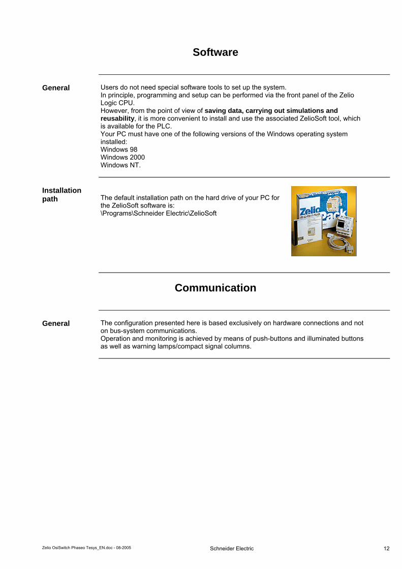
Software
General Users do not need special software tools to set up the system.
In principle, programming and setup can be performed via the front panel of the Zelio Logic CPU. However, from the point of view of saving data, carrying out simulations and reusability, it is more convenient to install and use the associated ZelioSoft tool, which is available for the PLC. Your PC must have one of the following versions of the Windows operating system installed: Windows 98 Windows 2000 Windows NT.
Installation path
The default installation path on the hard drive of your PC for the ZelioSoft software is: \Programs\Schneider Electric\ZelioSoft
Communication
General The configuration presented here is based exclusively on hardware connections and not
on bus-system communications. Operation and monitoring is achieved by means of push-buttons and illuminated buttons as well as warning lamps/compact signal columns.
Zelio OsiSwitch Phaseo Tesys_EN.doc - 08-2005
Schneider Electric
12

Implementation
Introduction This chapter describes the steps required to install the hardware and set up the software
for the task associated with the following application:
Function Functional description
All the conditions required to clear the group error must be met, i.e., motor circuit breaker switched on, crush protection OK, safety circuit on (optional in some cases). Opening the roller shutter: Press the “up” button to open the roller shutter (provided that the upper limit switch has not been actuated); the roller shutter stops moving if the stop button is pressed, the external pull switch is activated or a group fault occurs. The "up" button lights up to show that this movement has been selected. Closing the roller shutter: Press the “down” button to close the roller shutter (provided that the lower limit switch has not been actuated); the roller shutter stops moving if the stop button is pressed, the external pull switch or crush protection is activated or a group fault occurs. The "down" button lights up to show that this movement has been selected. Pull switch: Activating the pull switch will open the shutter if it is not completely open and the motor is idle; if the shutter is already open, activating the pull switch will cause it to close. Activating the switch again will stop the shutter. Motion detectors or induction loops: If the operator stops within range of the sensors, there will be a short delay and then the shutter will open. Having opened successfully, it will wait until the set rest period has elapsed, then close again. Crush protection: If crush protection is activated, the roller shutter will rise until the obstacle can no longer be sensed. Warning signal: A flashing light and/or klaxon indicates that the roller shutter is in motion.
Layout
Zelio OsiSwitch Phaseo Tesys_EN.doc - 08-2005
Schneider Electric
13

HMI
Introduction This application does not feature an HMI.
PLC
Introduction The PLC chapter describes the steps required to initialize, parameterize and program
the PLC logic in order to implement the functional description described above. The application program is created using ZelioSoft.
Creating a new program
1 When you open ZelioSoft for the first time, the data entry menu for choosing a new or existing program will appear. To create a new program, select “New Program”. A window will appear so that you can select the Zelio module (see opposite). First of all, please narrow the selection by clicking on the relevant image, then select the technical data/module type description in the lower window.
2 Once an existing module has
been selected, you can choose between two programming languages. The programming languages available are LD (Ladder Diagram) or FBD (Function Block Diagram).
Continued on next page
Zelio OsiSwitch Phaseo Tesys_EN.doc - 08-2005
Schneider Electric
14

3 In our example, FBD should be
selected, although the use of LD would be equally appropriate.
Loading an existing program
1 To load an existing program, click on the round “folder” button or select “Open” from the “File” menu. The default folder for loading a program is the "Z2USER" folder. However, you can use the browse function to access any other folder containing a program with the file extension *.zm2. Now open the “Example.zm2” program.
2 After opening the program, you should check that the module configuration in the software matches the module you actually have at hand. The easiest way to check this is by comparing the inscription on the Zelio PLC (on the right-hand side as you look at it from above) with the code displayed in the bottom right-hand corner of the screen. If the configuration does not match, it will not be possible to load the program into the controller! The module configuration cannot be modified retrospectively.
Zelio OsiSwitch Phaseo Tesys_EN.doc - 08-2005
Schneider Electric
15

Configuring the interface
1 Before you can transfer your program to the PLC, you need to configure your PC’s communication interface. To do this, select “COMMUNICATION setup” from the “Transfer” menu and then select the relevant port. The pull-down menu will contain the list of recognized ports, which will depend on the PC hardware and operating system. In this case, the first serial interface is selected -> “COM1“. If the PC is connected to the Zelio Logic controller via the programming cable, you can now test the connection by selecting “Test” from the configuration menu.
USB 1 Depending on the PC and operating system, "COM6" (or similar) will be displayed
along with "COM1" or "COM2", if no serial port is available or, for example, the USB has been mapped as serial. Please note that the Zelio package does not include a USB serial adapter. For more detailed information, please refer to the Zelio help function.
2 After this, the application program can be transferred to the PLC. To do this, select “Transfer“ from the menu bar, followed by “Transfer Program” and “PC > Module”.
3 Before starting the PLC, please read the safety warnings relating to your system and make sure that everyone is clear of any potential danger zone.
4 Once the program has been successfully transferred, you are free to start the Zelio Logic PLC. To do this, select “Transfer” from the menu bar again, only this time followed by “RUN Module”.
Zelio OsiSwitch Phaseo Tesys_EN.doc - 08-2005
Schneider Electric
16

Zelio OsiSwitch Phaseo Tesys_EN.doc - 08-2005
Schneider Electric
17
Data Exchange
Introduction There is no exchange of data between the various devices involved in this application
example.
Devices
Introduction Other than a motor circuit breaker, no settings need to be made in this application.

Zelio OsiSwitch Phaseo Tesys_EN.doc - 08-2005
Schneider Electric
18
Appendix
Detailed Component List
Item Qty Description Part No. Rev./ Vers.
Hardware components
1.1 1 Master switch VCF02GE 1.2 1 Emergency stop button housing XALK174G 1.3 3 Contactor, 9A, 24 V DC operated, 3-pole
AC3, 1x NO + 1x NC LC1D09BD
1.4 1 3-button push-button housing empty XALD03 1.5 2 Illuminated button green, flat ZB5AW333 1.6 2 Auxiliary switch module with green LED + 1
auxiliary switch (1x NO) ZB5AW0B31
1.7 1 Label holder 30x40 “up” ZBY2207 1.8 1 Label holder 30x40 “down” ZBY2208 1.9 1 Illuminated button red, flat ZB5AW343 1.10 1 Auxiliary switch module with red LED + 1
auxiliary switch (1x NO) ZB5AW0B42
1.11 1 Label holder 30x40 “stop” ZBY2304 1.12 1 Illuminated button blue, flat ZB5AW363 1.13 1 Auxiliary switch module with blue LED + 1
auxiliary switch (1x NO) ZB5AW0B61
1.14 1 Label holder 30x40 “emergency stop” ZBY22420001 1.15 1 Indicator lamp white, flat XB5AVB1 1.16 1 Label holder 30x40 “controller on“ ZBY2211 1.17 1 Compact signal station or flashing light XVBL0B5 1.18 2 Position switch Universal (final positions) XCKP2118P16 1.19 1 Position switch Universal
(pull switch) XCKD2145P16
1.20 1 Motor protection GV2ME07 1.21 2 Miniature circuit breaker C60N 1P 2A C 23726 1.22 1 Miniature circuit breaker C60N 1P+N 1A C 24183 1.23 1 Phaseo power supply
24 V DC/1.2 A ABL7CEM24012
1.24 1 ZELIO Logic Compact (PLC + ZelioSoft + programming cable)
SR2PACK2BD 2.0
1.25 1 (Zelio Logic Compact with 20 I/O, 24 V DC version, included in item 1.23, if ZelioSoft cable and software already present)
SR2B201BD 2.0
Alternatively to Motor protection witth Rev. contactors: Tesys U (pos. 1.26 - 1.29 ) 1.26 1 Reversing contactor combination 12 A 24 V
DC LU2B12BL
1.27 1 Control unit 1.25 – 5 A 24 V DC LUCA05BL 1.28 1 Function module 2 auxiliary contacts LUFN20 1.29 1 Auxiliary contacts 2x NO (fault and ready) LUA1C20
Software components Item Qty Description Part No.
Rev./ Vers.
2.1 1 ZelioSoft (included in item 1.26) SR2SFT01 2.0 2.2 1 ZelioSoft programming cable (included in
item 1.26) SR2CBL01
2.2 1 Optional: SR-EEPROM card SR2ME01

Zelio OsiSwitch Phaseo Tesys_EN.doc - 08-2005
Schneider Electric
19
Component Protection Classes
Components In the field, on site IP55/IP65
Front IP65 Control cubicle IP20
Master switch X
Recommended installation locations/ Protection class Emergency stop button housing X Motor circuit breaker X Contactor, 9A, 24 V DC operated,
3-pole AC 3, 1x NO + 1x NC X
3-button push-button housing, empty X Illuminated buttons, all colors, flat X Auxiliary switch module with LED + 1
auxiliary switch (1x NO), all colors X
Label holder 30x40, all texts X Compact signal station or flashing light X Position switch Universal X TeSys U complete unit X Miniature circuit breaker, all types and
ratings X
Phaseo power supply 24 V DC/1.2 A X
ZELIO Logic PLC X

Component Features
Zelio PLC: Zelio Logic PLC:
Zelio Logic Compact – SR2PACK2BD (package includes software and hardware, plus programming cable): • 24 V DC • 12 digital inputs • 8 digital relay outputs • • Front operator panel for Ladder and FBD programming (no PC required); also
possible via PC using ZelioSoft software.
Continued on next page
Zelio OsiSwitch Phaseo Tesys_EN.doc - 08-2005
Schneider Electric
20

Zelio PLC, continued
Zelio PLC Zelio software functions – LADDER: • User-friendly “free input” mode: LADDER or FBD (electrical symbols)
• 120 lines for control tasks • 5 contacts + 1 memory per program line •
28 auxilary relays
8 counter comparators
LCD screen withprogramableback lighting
automatic 1 hour clockchange: summer/winter
diversity of coilfunctions: with memory(set/reset), remote switch,contactor,
16 text functionblocks
16 timers
16 up/down counter
1 fast counter
16 analogueComparators
8 clocks
Zelio software functions – Function Block Diagram/FBD:
Continued on next page
Zelio OsiSwitch Phaseo Tesys_EN.doc - 08-2005
Schneider Electric
21

Zelio PLC, continued
Graphs showing average cycle times of the Zelio PLC when various elements are used.
Zelio OsiSwitch Phaseo Tesys_EN.doc - 08-2005
Schneider Electric
22
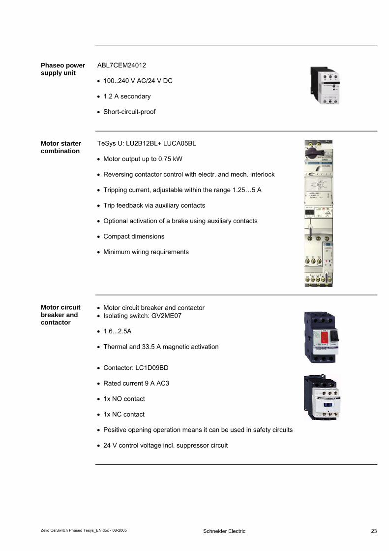
Phaseo power supply unit
ABL7CEM24012 • 100..240 V AC/24 V DC
• 1.2 A secondary • Short-circuit-proof
Motor starter combination
TeSys U: LU2B12BL+ LUCA05BL • Motor output up to 0.75 kW • Reversing contactor control with electr. and mech. interlock • Tripping current, adjustable within the range 1.25…5 A • Trip feedback via auxiliary contacts • Optional activation of a brake using auxiliary contacts • Compact dimensions • Minimum wiring requirements
Motor circuit breaker and contactor
• Motor circuit breaker and contactor • Isolating switch: GV2ME07
• 1.6...2.5A
• Thermal and 33.5 A magnetic activation
• Contactor: LC1D09BD
• Rated current 9 A AC3 • 1x NO contact • 1x NC contact • Positive opening operation means it can be used in safety circuits • 24 V control voltage incl. suppressor circuit
Zelio OsiSwitch Phaseo Tesys_EN.doc - 08-2005
Schneider Electric
23

Schneider Electric GmbH Steinheimer Strasse 117 D - 63500 Seligenstadt Germany Zelio OsiSwitch Phaseo Tesys_EN.doc
As standards, specifications and designs change from time to time, please ask for confirmation of the information given in this publication. 24
Contact
Author Phone E-mail
Schneider Electric GmbH Customer & Market System & Architecture Architecture Definition Support
+49 6182 81 2555 [email protected]