Smart relays Zelio Logic - Elmatik Electric... · Alarm management software (see page 37) “Zelio...
48
Smart relays Zelio Logic Catalogue October 2011
Transcript of Smart relays Zelio Logic - Elmatik Electric... · Alarm management software (see page 37) “Zelio...
Smart relaysZelio Logic
Catalogue
October 2011

All technical information about products listed in this catalogue are now available on:www.schneider-electric.comBrowse the “product data sheet” to check out :
p characteristics, p dimensions, p curves, ... p and also the links to the user guides and
the CAD files.
1 From the home page, type the model number* into the “Search” box.
2 Under ”All” tab, click the model number that interests you.
* type the model number without any blank, replace “p” by “*”
89,5
80
8222,5
78
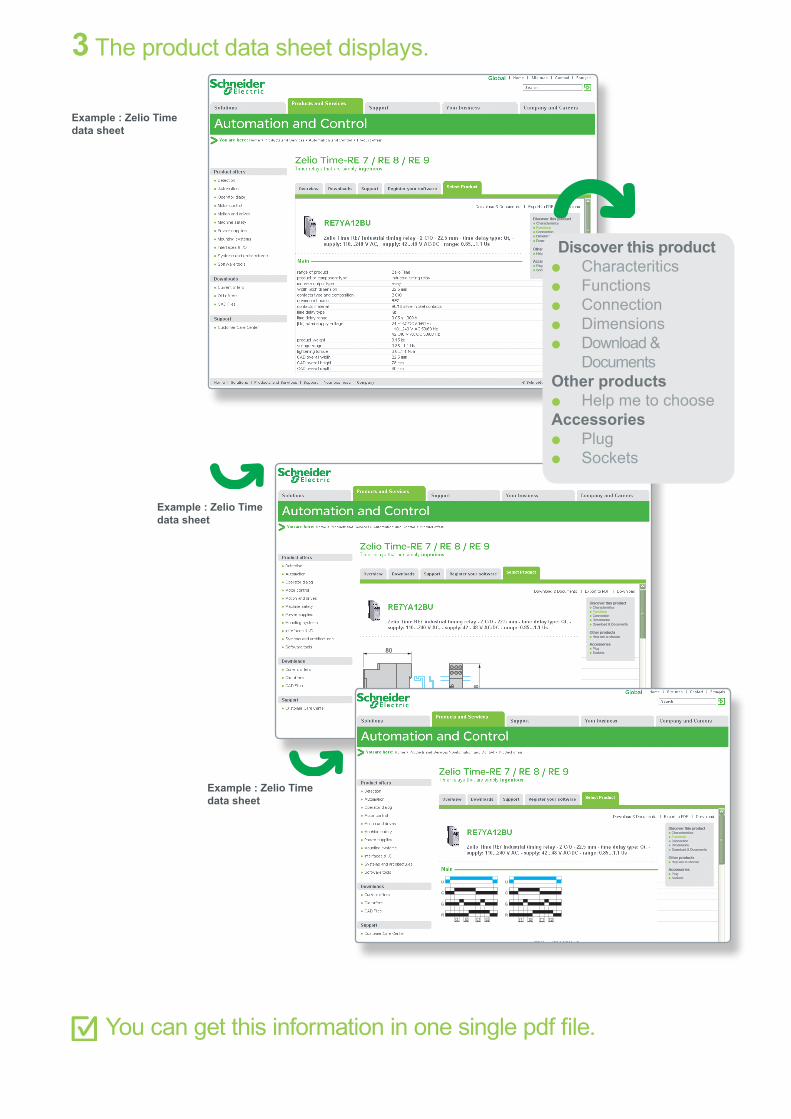
3 The product data sheet displays.
You can get this information in one single pdf file.
Discover this product p Characteritics p Functions p Connection p Dimensions p Download &
DocumentsOther products
p Help me to chooseAccessories
p Plug p Sockets
Example : Zelio Time data sheet
Example : Zelio Time data sheet
Example : Zelio Time data sheet
U
C
t1
G
Rt'1t2 t'2
U
C
t1
G
Rt'1t2 t'2

2
2
1
3
4
5
6
7
8
9
10
3
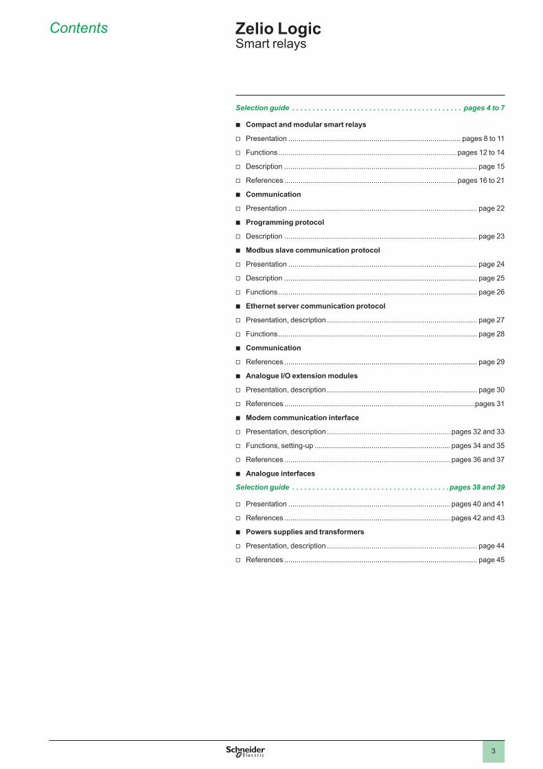
Contents
Selection guide . . . . . . . . . . . . . . . . . . . . . . . . . . . . . . . . . . . . . . . . . . pages 4 to 7
b Compact and modular smart relays
v Presentation ..................................................................................... pages 8 to 11
v Functions ........................................................................................pages 12 to 14
v Description ............................................................................................... page 15
v References .....................................................................................pages 16 to 21
b Communication
v Presentation ............................................................................................. page 22
b Programming protocol
v Description ............................................................................................... page 23
b Modbus slave communication protocol
v Presentation ............................................................................................. page 24
v Description ............................................................................................... page 25
v Functions .................................................................................................. page 26
b Ethernet server communication protocol
v Presentation, description .......................................................................... page 27
v Functions .................................................................................................. page 28
b Communication
v References ............................................................................................... page 29
b Analogue I/O extension modules
v Presentation, description .......................................................................... page 30
v References ..............................................................................................pages 31
b Modem communication interface
v Presentation, description .............................................................pages 32 and 33
v Functions, setting-up ...................................................................pages 34 and 35
v References ..................................................................................pages 36 and 37
b Analogue interfaces
Selection guide . . . . . . . . . . . . . . . . . . . . . . . . . . . . . . . . . . . . . . .pages 38 and 39
v Presentation ................................................................................pages 40 and 41
v References ..................................................................................pages 42 and 43
b Powers supplies and transformers
v Presentation, description .......................................................................... page 44
v References ............................................................................................... page 45
Zelio Logic Smart relays
2
1
3
4
5
6
7
8
9
10
2
1
3
4
5
6
7
8
9
10
4
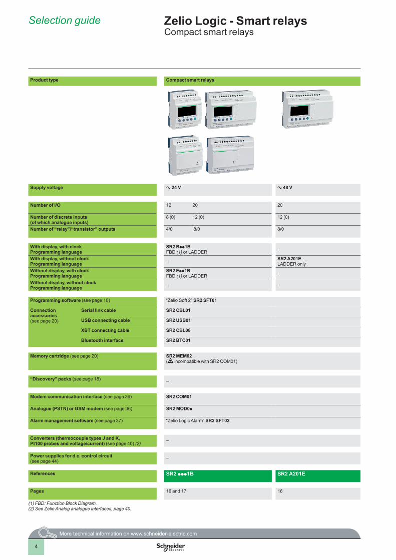
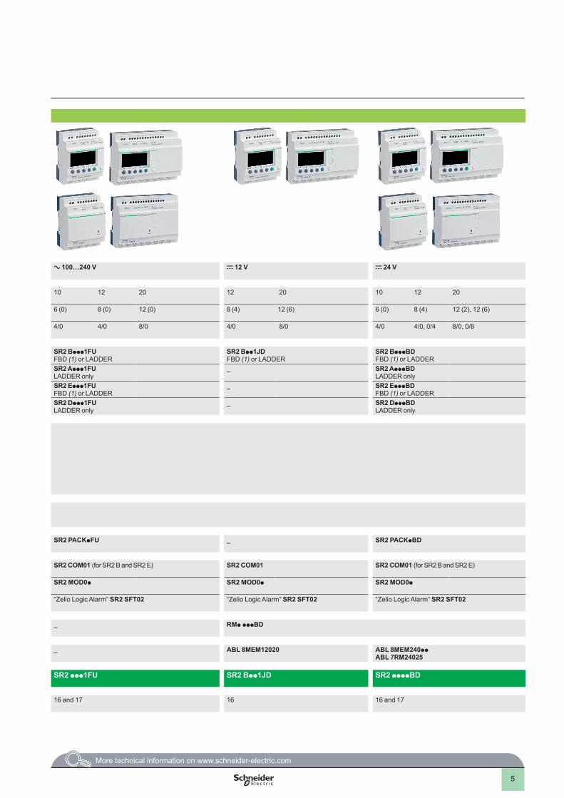
Product type Compact smart relays
Supply voltage a 24 V a 48 V a 100…240 V c 12 V c 24 V
Number of I/O 12 20 20 10 12 20 12 20 10 12 20
Number of discrete inputs (of which analogue inputs)
8 (0) 12 (0) 12 (0) 6 (0) 8 (0) 12 (0) 8 (4) 12 (6) 6 (0) 8 (4) 12 (2), 12 (6)
Number of “relay”/“transistor” outputs 4/0 8/0 8/0 4/0 4/0 8/0 4/0 8/0 4/0 4/0, 0/4 8/0, 0/8
With display, with clockProgramming language
SR2 Bpp1BFBD (1) or LADDER
_ SR2 Bppp1FUFBD (1) or LADDER
SR2 Bpp1JDFBD (1) or LADDER
SR2 BpppBDFBD (1) or LADDER
With display, without clockProgramming language
_ SR2 A201ELADDER only
SR2 Appp1FULADDER only
_ SR2 ApppBDLADDER only
Without display, with clockProgramming language
SR2 Epp1BFBD (1) or LADDER
_ SR2 Eppp1FUFBD (1) or LADDER
_ SR2 EpppBDFBD (1) or LADDER
Without display, without clockProgramming language
_ _ SR2 Dppp1FULADDER only
_ SR2 DpppBDLADDER only
Programming software (see page 10) “Zelio Soft 2” SR2 SFT01
Connection accessories(see page 20)
Serial link cable SR2 CBL01
USB connecting cable SR2 USB01
XBT connecting cable SR2 CBL08
Bluetooth interface SR2 BTC01
Memory cartridge (see page 20) SR2 MEM02(d incompatible with SR2 COM01)
“Discovery” packs (see page 18) _ SR2 PACKpFU _ SR2 PACKpBD
Modem communication interface (see page 36) SR2 COM01 SR2 COM01 (for SR2 B and SR2 E) SR2 COM01 SR2 COM01 (for SR2 B and SR2 E)
Analogue (PSTN) or GSM modem (see page 36) SR2 MOD0p SR2 MOD0p SR2 MOD0p SR2 MOD0p
Alarm management software (see page 37) “Zelio Logic Alarm” SR2 SFT02 “Zelio Logic Alarm” SR2 SFT02 “Zelio Logic Alarm” SR2 SFT02 “Zelio Logic Alarm” SR2 SFT02
Converters (thermocouple types J and K, Pt100 probes and voltage/current) (see page 40) (2)
_ _ RMp pppBD
Power supplies for d.c. control circuit(see page 44)
_ _ ABL 8MEM12020 ABL 8MEM240ppABL 7RM24025
References SR2 ppp1B SR2 A201E SR2 ppp1FU SR2 Bpp1JD SR2 ppppBD
Pages 16 and 17 16 16 and 17 16 16 and 17
(1) FBD: Function Block Diagram.(2) See Zelio Analog analogue interfaces, page 40.
Selection guide Zelio Logic - Smart relaysCompact smart relays
1
2
3
4
5
6
7
8
9
10
5
Product type Compact smart relays
Supply voltage a 24 V a 48 V a 100…240 V c 12 V c 24 V
Number of I/O 12 20 20 10 12 20 12 20 10 12 20
Number of discrete inputs (of which analogue inputs)
8 (0) 12 (0) 12 (0) 6 (0) 8 (0) 12 (0) 8 (4) 12 (6) 6 (0) 8 (4) 12 (2), 12 (6)
Number of “relay”/“transistor” outputs 4/0 8/0 8/0 4/0 4/0 8/0 4/0 8/0 4/0 4/0, 0/4 8/0, 0/8
With display, with clockProgramming language
SR2 Bpp1BFBD (1) or LADDER
_ SR2 Bppp1FUFBD (1) or LADDER
SR2 Bpp1JDFBD (1) or LADDER
SR2 BpppBDFBD (1) or LADDER
With display, without clockProgramming language
_ SR2 A201ELADDER only
SR2 Appp1FULADDER only
_ SR2 ApppBDLADDER only
Without display, with clockProgramming language
SR2 Epp1BFBD (1) or LADDER
_ SR2 Eppp1FUFBD (1) or LADDER
_ SR2 EpppBDFBD (1) or LADDER
Without display, without clockProgramming language
_ _ SR2 Dppp1FULADDER only
_ SR2 DpppBDLADDER only
Programming software (see page 10) “Zelio Soft 2” SR2 SFT01
Connection accessories(see page 20)
Serial link cable SR2 CBL01
USB connecting cable SR2 USB01
XBT connecting cable SR2 CBL08
Bluetooth interface SR2 BTC01
Memory cartridge (see page 20) SR2 MEM02(d incompatible with SR2 COM01)
“Discovery” packs (see page 18) _ SR2 PACKpFU _ SR2 PACKpBD
Modem communication interface (see page 36) SR2 COM01 SR2 COM01 (for SR2 B and SR2 E) SR2 COM01 SR2 COM01 (for SR2 B and SR2 E)
Analogue (PSTN) or GSM modem (see page 36) SR2 MOD0p SR2 MOD0p SR2 MOD0p SR2 MOD0p
Alarm management software (see page 37) “Zelio Logic Alarm” SR2 SFT02 “Zelio Logic Alarm” SR2 SFT02 “Zelio Logic Alarm” SR2 SFT02 “Zelio Logic Alarm” SR2 SFT02
Converters (thermocouple types J and K, Pt100 probes and voltage/current) (see page 40) (2)
_ _ RMp pppBD
Power supplies for d.c. control circuit(see page 44)
_ _ ABL 8MEM12020 ABL 8MEM240ppABL 7RM24025
References SR2 ppp1B SR2 A201E SR2 ppp1FU SR2 Bpp1JD SR2 ppppBD
Pages 16 and 17 16 16 and 17 16 16 and 17
(1) FBD: Function Block Diagram.(2) See Zelio Analog analogue interfaces, page 40.
1
2
3
4
5
6
7
8
9
10
6
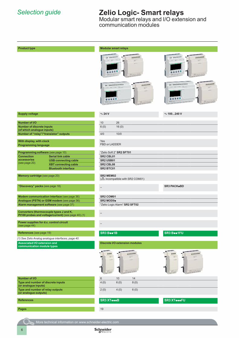
Product type Modular smart relays
Supply voltage a 24 V a 100...240 V c 12 V c 24 V
Number of I/O 10 26 26 10 26Number of discrete inputs (of which analogue inputs)
6 (0) 16 (0) 16 (6) 6 (4) 16 (6)
Number of “relay”/“transistor” outputs 4/0 10/0 10/0 4/0, 0/4 10/0, 0/10
With display, with clock YesFBD or LADDERProgramming language
Programming software (see page 10) “Zelio Soft 2” SR2 SFT01Connection accessories(see page 20)
Serial link cable SR2 CBL01USB connecting cable SR2 USB01XBT connecting cable SR2 CBL08Bluetooth interface SR2 BTC01
Memory cartridge (see page 20) SR2 MEM02(d incompatible with SR2 COM01)
“Discovery” packs (see page 18) _ SR3 PACKpBD _ SR3 PACKpBD
Modem communication interface (see page 36) SR2 COM01Analogue (PSTN) or GSM modem (see page 36) SR2 MOD0p
Alarm management software (see page 37) “Zelio Logic Alarm” SR2 SFT02
Converters (thermocouple types J and K, Pt100 probes and voltage/current) (see page 40) (1)
_ RMp pppBD
Power supplies for d.c. control circuit (see page 44)
_ ABL 8MEM12020 ABL 8MEM24006, ABL 8MEM24012, ABL 7RM24025
References (see page 19) SR3 Bpp1B SR3 Bpp1FU SR3 B261JD SR3 BpppBD(1) See Zelio Analog analogue interfaces, page 40.Associated I/O extension and communication module types
Discrete I/O extension modules Discrete I/O extension modules Network communication modules I/O extension modulesModbus salve Ethernet server Analogue Discrete
Number of I/O 6 10 14 6 10 14 b Number of words:v 4 (inputs)v 4 (outputs)v 4 (clock)v 1 (status)
b Number of words:v 4 (inputs)v 4 (outputs)v 4 (clock)v 1 (status)
4 6 10 14Type and number of discrete inputs (or analogue inputs)
4 (0) 6 (0) 8 (0) 4 (0) 6 (0) 8 (0) 0 (2) 4 (0) 6 (0) 8 (0)
Type and number of relay outputs(or analogue outputs)
2 (0) 4 (0) 6 (0) 2 (0) 4 (0) 6 (0) 0 (2) 2 (0) 4 (0) 6 (0)
References SR3 XTpppB SR3 XTpppFU SR3 XTpppJD SR3 MBU01BD SR3 NET01BD SR3 XT43BD SR3 XTpppBD
Pages 19 19 29 31 19
Selection guide Zelio Logic- Smart relays Modular smart relays and I/O extension and communication modules
1
2
3
4
5
6
7
8
9
10
7
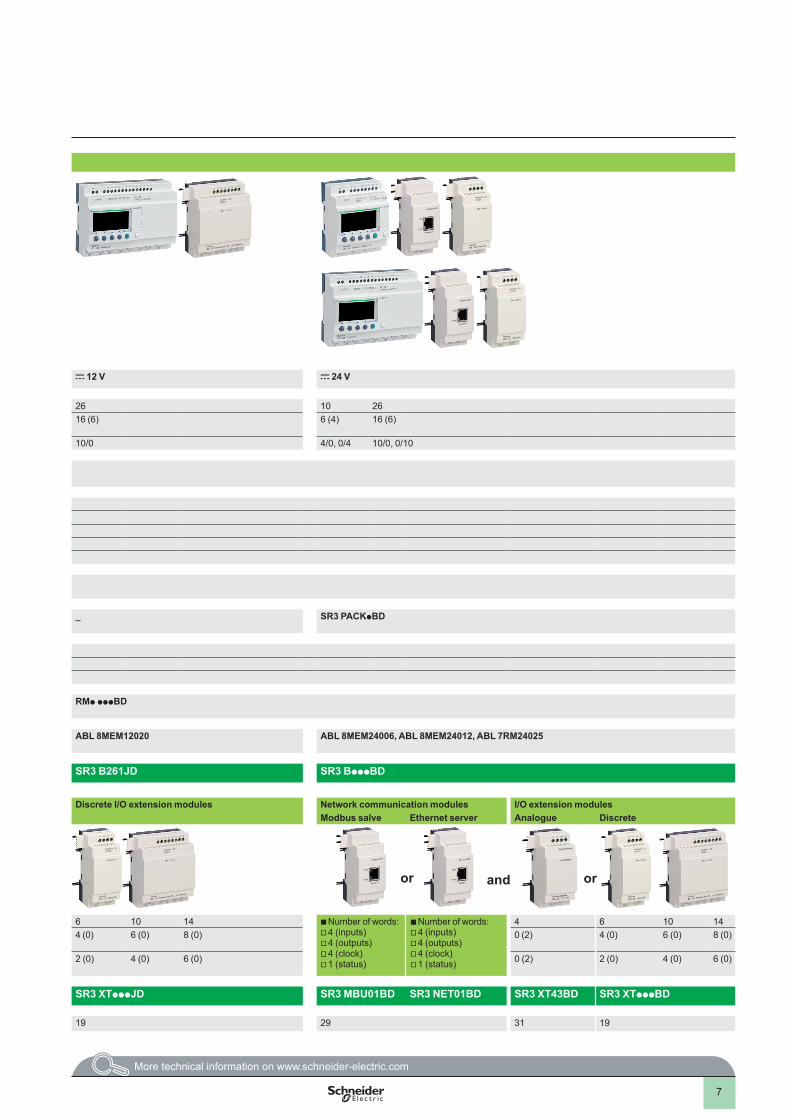
Product type Modular smart relays
Supply voltage a 24 V a 100...240 V c 12 V c 24 V
Number of I/O 10 26 26 10 26Number of discrete inputs (of which analogue inputs)
6 (0) 16 (0) 16 (6) 6 (4) 16 (6)
Number of “relay”/“transistor” outputs 4/0 10/0 10/0 4/0, 0/4 10/0, 0/10
With display, with clock YesFBD or LADDERProgramming language
Programming software (see page 10) “Zelio Soft 2” SR2 SFT01Connection accessories(see page 20)
Serial link cable SR2 CBL01USB connecting cable SR2 USB01XBT connecting cable SR2 CBL08Bluetooth interface SR2 BTC01
Memory cartridge (see page 20) SR2 MEM02(d incompatible with SR2 COM01)
“Discovery” packs (see page 18) _ SR3 PACKpBD _ SR3 PACKpBD
Modem communication interface (see page 36) SR2 COM01Analogue (PSTN) or GSM modem (see page 36) SR2 MOD0p
Alarm management software (see page 37) “Zelio Logic Alarm” SR2 SFT02
Converters (thermocouple types J and K, Pt100 probes and voltage/current) (see page 40) (1)
_ RMp pppBD
Power supplies for d.c. control circuit (see page 44)
_ ABL 8MEM12020 ABL 8MEM24006, ABL 8MEM24012, ABL 7RM24025
References (see page 19) SR3 Bpp1B SR3 Bpp1FU SR3 B261JD SR3 BpppBD(1) See Zelio Analog analogue interfaces, page 40.Associated I/O extension and communication module types
Discrete I/O extension modules Discrete I/O extension modules Network communication modules I/O extension modulesModbus salve Ethernet server Analogue Discrete
Number of I/O 6 10 14 6 10 14 b Number of words:v 4 (inputs)v 4 (outputs)v 4 (clock)v 1 (status)
b Number of words:v 4 (inputs)v 4 (outputs)v 4 (clock)v 1 (status)
4 6 10 14Type and number of discrete inputs (or analogue inputs)
4 (0) 6 (0) 8 (0) 4 (0) 6 (0) 8 (0) 0 (2) 4 (0) 6 (0) 8 (0)
Type and number of relay outputs(or analogue outputs)
2 (0) 4 (0) 6 (0) 2 (0) 4 (0) 6 (0) 0 (2) 2 (0) 4 (0) 6 (0)
References SR3 XTpppB SR3 XTpppFU SR3 XTpppJD SR3 MBU01BD SR3 NET01BD SR3 XT43BD SR3 XTpppBD
Pages 19 19 29 31 19
andor or
1
2
3
4
5
6
7
8
9
10
8
Presentation Zelio Logic smart relays are designed for use in small automated systems. They are used in both the industrial and commercial sectors. b For industry: v automation of small finishing, production, assembly or packaging machines,v decentralised automation of ancillary equipment of large and medium-sized machines (textile, plastics, materials processing sectors, etc.),v automation systems for agricultural machinery (irrigation, pumping, greenhouses etc.)
b For the commercial/building sectors: v automation of barriers, roller shutters, access control,v automation of lighting systems,v automation of compressors and air conditioning systems.v etc.
Their compact size and ease of setting-up make them a competitive alternative to solutions based on cabled logic or specific cards.
b ProgrammingSimple programming, ensured by the universal nature of the languages, meets all the requirements of automation specialists and also the needs of the electrician.Programming can be performed:v independently, using the buttons on the Zelio Logic smart relay (ladder language),v on a PC using “Zelio Soft 2” software.When using a PC, programming can be performed either in LADDER language or in function block diagram (FBD) language, see page 10.
Backlighting of the LCD display (1) is obtained by activating one of the 6 programming buttons on the Zelio Logic smart relay or by programming with “Zelio Soft 2” software (example: flashing in the event of a malfunction).
The autonomous operating time of the clock, assured by a lithium battery, is 10 years.Data backup (preset values and current values) is provided by an EEPROM Flash memory (10 years).
Compact smart relaysCompact smart relays meet requirements for simple automation systems. The number of inputs/outputs can be:b 12 or 20 I/O, supplied with a 24 V or c 12 V,b 20 I/O, supplied with a 48 V,b 10, 12 or 20 I/O, supplied with a 100…240 V or c 24 V.
Modular smart relays and extensionsThe number of inputs/outputs for modular smart relays can be:b 26 I/O, supplied with c 12 V,b 10 or 26 I/O, supplied with a 24 V, a 100…240 V or c 24 V
To improve performance and flexibility, Zelio Logic modular smart relays can be fitted with communication modules and I/O extension modules to obtain a maximum of 40 I/O:b Modbus or Ethernet communication modules, supplied with c 24 V via the Zelio Logic smart relay at the same voltage.b analogue I/O extension modules with 4 I/O, supplied with c 24 V via the Zelio Logic smart relay at the same voltage,b discrete I/O extension modules with 6, 10 or 14 I/O, supplied via the Zelio Logic smart relay at the same voltage.(1) LCD: Liquid Crystal Display.d The order shown above must be observed when using
a Modbus slave or Ethernet server communication module and a discrete or analogue I/O extension module.An I/O extension module cannot be fitted before the Modbus slave communication module.
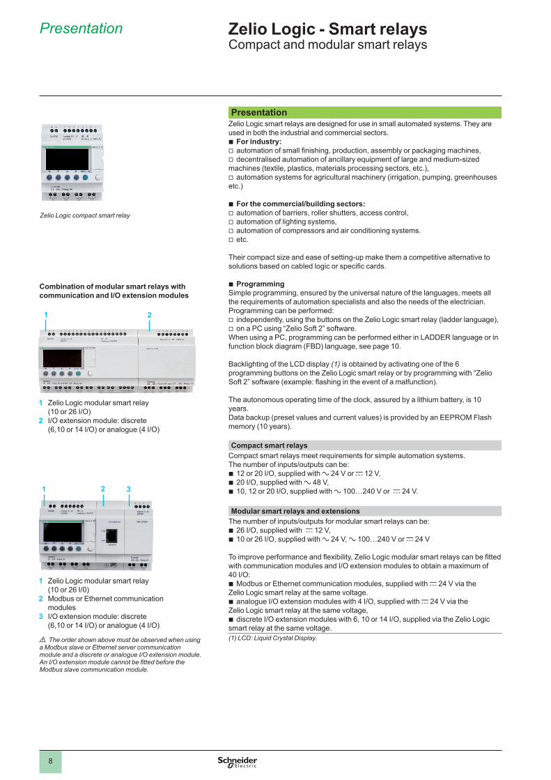
Zelio Logic compact smart relay
Combination of modular smart relays with communication and I/O extension modules
1 Zelio Logic modular smart relay(10 or 26 I/O)
2 I/O extension module: discrete(6,10 or 14 I/O) or analogue (4 I/O)
1 Zelio Logic modular smart relay (10 or 26 I/0)
2 Modbus or Ethernet communication modules
3 I/O extension module: discrete(6,10 or 14 I/O) or analogue (4 I/O)
1 2 3
1 2
Presentation Zelio Logic - Smart relaysCompact and modular smart relays
1
2
3
4
5
6
7
8
9
10
9
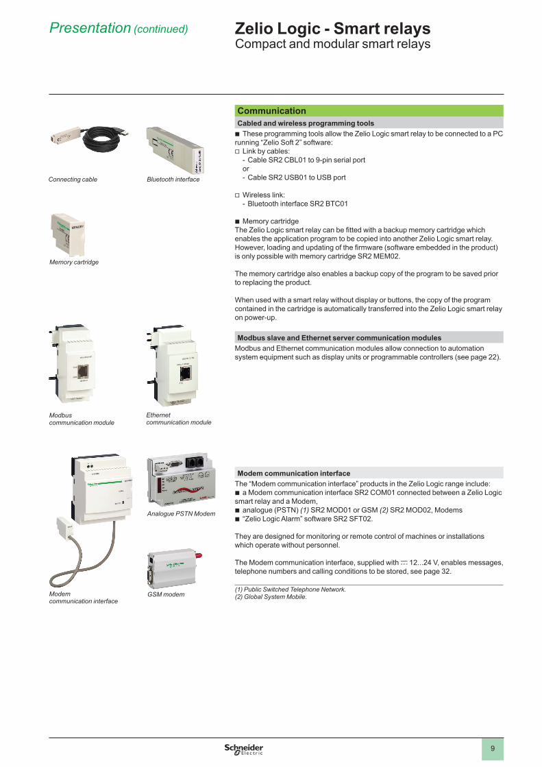
CommunicationCabled and wireless programming tools
b These programming tools allow the Zelio Logic smart relay to be connected to a PC running “Zelio Soft 2” software:v Link by cables:
- Cable SR2 CBL01 to 9-pin serial portor- Cable SR2 USB01 to USB port
v Wireless link:- Bluetooth interface SR2 BTC01
b Memory cartridge The Zelio Logic smart relay can be fitted with a backup memory cartridge which enables the application program to be copied into another Zelio Logic smart relay. However, loading and updating of the firmware (software embedded in the product) is only possible with memory cartridge SR2 MEM02.
The memory cartridge also enables a backup copy of the program to be saved prior to replacing the product.
When used with a smart relay without display or buttons, the copy of the program contained in the cartridge is automatically transferred into the Zelio Logic smart relay on power-up.
Modbus slave and Ethernet server communication modules Modbus and Ethernet communication modules allow connection to automation system equipment such as display units or programmable controllers (see page 22).
Modem communication interface The “Modem communication interface” products in the Zelio Logic range include:b a Modem communication interface SR2 COM01 connected between a Zelio Logic smart relay and a Modem,b analogue (PSTN) (1) SR2 MOD01 or GSM (2) SR2 MOD02, Modemsb “Zelio Logic Alarm” software SR2 SFT02.
They are designed for monitoring or remote control of machines or installations which operate without personnel.
The Modem communication interface, supplied with c 12...24 V, enables messages, telephone numbers and calling conditions to be stored, see page 32.
(1) Public Switched Telephone Network.(2) Global System Mobile.
Bluetooth interfaceConnecting cable
Modbuscommunication module
Ethernetcommunication module
Modemcommunication interface
Memory cartridge
Analogue PSTN Modem
GSM modem
Zelio Logic - Smart relaysCompact and modular smart relays
Presentation (continued)
1
2
3
4
5
6
7
8
9
10
10
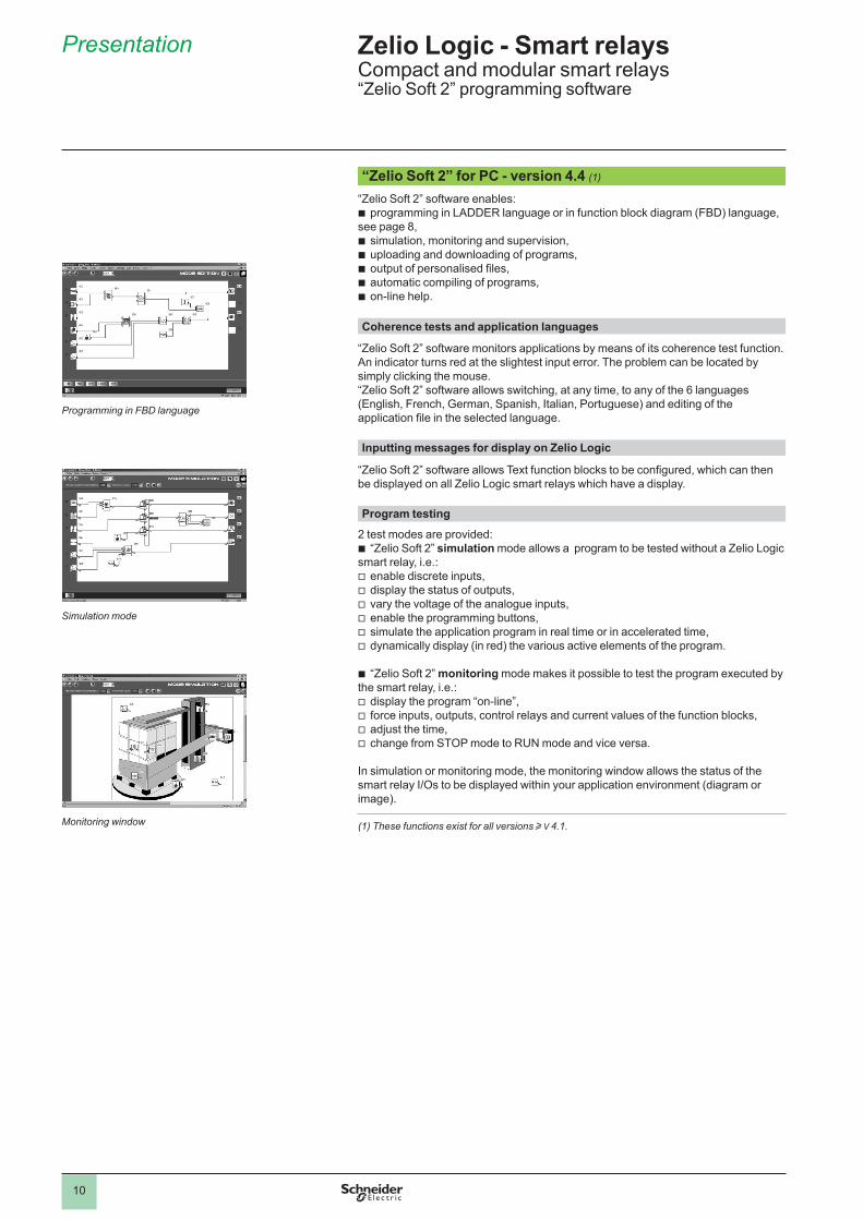
“Zelio Soft 2” for PC - version 4.4 (1)
“Zelio Soft 2” software enables:b programming in LADDER language or in function block diagram (FBD) language, see page 8,b simulation, monitoring and supervision,b uploading and downloading of programs,b output of personalised files,b automatic compiling of programs,b on-line help. Coherence tests and application languages
“Zelio Soft 2” software monitors applications by means of its coherence test function. An indicator turns red at the slightest input error. The problem can be located by simply clicking the mouse. “Zelio Soft 2” software allows switching, at any time, to any of the 6 languages (English, French, German, Spanish, Italian, Portuguese) and editing of the application file in the selected language. Inputting messages for display on Zelio Logic
“Zelio Soft 2” software allows Text function blocks to be configured, which can then be displayed on all Zelio Logic smart relays which have a display. Program testing
2 test modes are provided: b “Zelio Soft 2” simulation mode allows a program to be tested without a Zelio Logic smart relay, i.e.:v enable discrete inputs,v display the status of outputs,v vary the voltage of the analogue inputs,v enable the programming buttons,v simulate the application program in real time or in accelerated time,v dynamically display (in red) the various active elements of the program.
b “Zelio Soft 2” monitoring mode makes it possible to test the program executed by the smart relay, i.e.:v display the program “on-line”,v force inputs, outputs, control relays and current values of the function blocks,v adjust the time,v change from STOP mode to RUN mode and vice versa.
In simulation or monitoring mode, the monitoring window allows the status of the smart relay I/Os to be displayed within your application environment (diagram or image).
(1) These functions exist for all versions u V 4.1.
Zelio Logic - Smart relaysCompact and modular smart relays“Zelio Soft 2” programming software
Presentation
Programming in FBD language
Simulation mode
Monitoring window
1
2
3
4
5
6
7
8
9
10
11
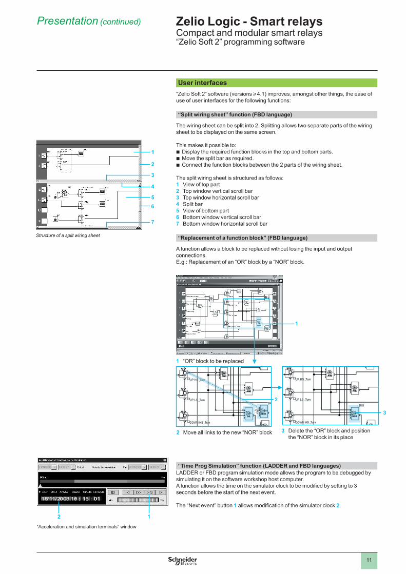
User interfaces“Zelio Soft 2” software (versions u 4.1) improves, amongst other things, the ease of use of user interfaces for the following functions: “Split wiring sheet” function (FBD language)
The wiring sheet can be split into 2. Splitting allows two separate parts of the wiring sheet to be displayed on the same screen.
This makes it possible to:b Display the required function blocks in the top and bottom parts.b Move the split bar as required.b Connect the function blocks between the 2 parts of the wiring sheet. The split wiring sheet is structured as follows:1 View of top part2 Top window vertical scroll bar3 Top window horizontal scroll bar4 Split bar5 View of bottom part6 Bottom window vertical scroll bar7 Bottom window horizontal scroll bar
“Replacement of a function block” (FBD language)
A function allows a block to be replaced without losing the input and output connections.E.g.: Replacement of an “OR” block by a “NOR” block.
zzzz
“Time Prog Simulation” function (LADDER and FBD languages)LADDER or FBD program simulation mode allows the program to be debugged by simulating it on the software workshop host computer.A function allows the time on the simulator clock to be modified by setting to 3 seconds before the start of the next event.
The “Next event” button 1 allows modification of the simulator clock 2.
1 “OR” block to be replaced
1
2 Move all links to the new “NOR” block
2
3 Delete the “OR” block and positionthe “NOR” block in its place
3
“Acceleration and simulation terminals” window
2 1
Zelio Logic - Smart relaysCompact and modular smart relays“Zelio Soft 2” programming software
Presentation (continued)
1
2
3
4
56
7
Structure of a split wiring sheet
1
2
3
4
5
6
7
8
9
10
12
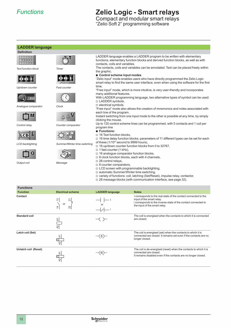
LADDER languageDefinition
Text function block
Up/down counter
Analogue comparator
Control relay
LCD backlighting
Output coil
Timer
Fast counter
Clock
Counter comparator
Summer/Winter time switching
Message
LADDER language enables a LADDER program to be written with elementary functions, elementary function blocks and derived function blocks, as well as with contacts, coils and variables.The contacts, coils and variables can be annotated. Text can be placed freely within the graphic.b Control scheme input modes“Zelio input” mode enables users who have directly programmed the Zelio Logic smart relay to find the same user interface, even when using the software for the first time.“Free input” mode, which is more intuitive, is very user-friendly and incorporates many additional features. With LADDER programming language, two alternative types of symbol can be used: v LADDER symbols,v electrical symbols.“Free input” mode also allows the creation of mnemonics and notes associated with each line of the program.Instant switching from one input mode to the other is possible at any time, by simply clicking the mouse.Up to 120 control scheme lines can be programmed, with 5 contacts and 1 coil per program lineb Functions:v 16 Text function blocks,v 16 time delay function blocks; parameters of 11 different types can be set for each of these (1/10th second to 9999 hours),v 16 up/down counter function blocks from 0 to 32767,v 1 fast counter (1 kHz),v 16 analogue comparator function blocks,v 8 clock function blocks, each with 4 channels,v 28 control relays,v 8 counter comparators,v LCD screen with programmable backlighting,v automatic Summer/Winter time switching,v variety of functions: coil, latching (Set/Reset), impulse relay, contactor,v 28 message blocks (with communication interface, see page 32).
Functions Function Electrical scheme LADDER language Notes
Contact I corresponds to the real state of the contact connected to the input of the smart relay.i corresponds to the inverse state of the contact connected to the input of the smart relay.
Standard coil The coil is energised when the contacts to which it is connected are closed.
Latch coil (Set) The coil is energised (set) when the contacts to which it is connected are closed. It remains set even if the contacts are no longer closed.
Unlatch coil (Reset) The coil is de-energised (reset) when the contacts to which it is connected are closed.It remains disabled even if the contacts are no longer closed.
1314 22
21
or or
I
i
A1A2
A1A2
S
A1A2
R
Zelio Logic - Smart relaysCompact and modular smart relays“Zelio Soft 2” programming software
Functions
1
2
3
4
5
6
7
8
9
10
13
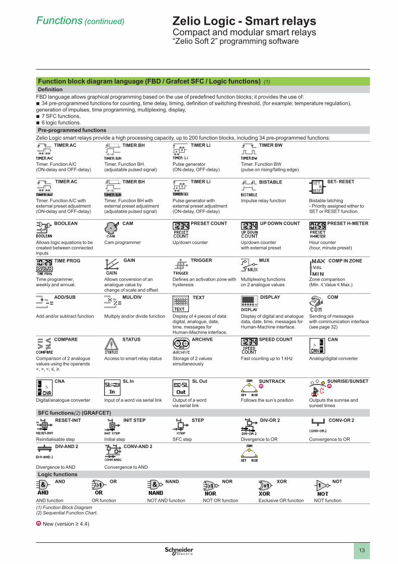
Function block diagram language (FBD / Grafcet SFC / Logic functions) (1)Definition
FBD language allows graphical programming based on the use of predefined function blocks; it provides the use of:b 34 pre-programmed functions for counting, time delay, timing, definition of switching threshold, (for example: temperature regulation), generation of impulses, time programming, multiplexing, display,b 7 SFC functions,b 6 logic functions.Pre-programmed functions
Zelio Logic smart relays provide a high processing capacity, up to 200 function blocks, including 34 pre-programmed functions: TIMER AC TIMER BH TIMER Li TIMER BW
Timer. Function A/C(ON-delay and OFF-delay)
Timer. Function BH.(adjustable pulsed signal)
Pulse generator (ON-delay, OFF-delay)
Timer. Function BW(pulse on rising/falling edge)
TIMER AC TIMER BH TIMER Li BISTABLE SET- RESET
Timer. Function A/C with external preset adjustment (ON-delay and OFF-delay)
Timer. Function BH with external preset adjustment(adjustable pulsed signal)
Pulse generator with external preset adjustment (ON-delay, OFF-delay)
Impulse relay function Bistable latching - Priority assigned either to SET or RESET function
BOOLEAN CAM PRESET COUNT UP DOWN COUNT PRESET H-METER
Allows logic equations to be created between connected inputs
Cam programmer Up/down counter Up/down counter with external preset
Hour counter(hour, minute preset)
TIME PROG GAIN TRIGGER MUX COMP IN ZONE
Time programmer, weekly and annual.
Allows conversion of an analogue value by change of scale and offset.
Defines an activation zone with hysteresis
Multiplexing functions on 2 analogue values
Zone comparison(Min. y Value y Max.)
ADD/SUB MUL/DIV TEXT DISPLAY COM
Add and/or subtract function Multiply and/or divide function Display of 4 pieces of data: digital, analogue, date, time, messages for Human-Machine interface.
Display of digital and analogue data, date, time, messages for Human-Machine interface.
Sending of messages with communication interface (see page 32)
COMPARE STATUS ARCHIVE SPEED COUNT CAN
Comparison of 2 analogue values using the operands =, >, <, y, u.
Access to smart relay status Storage of 2 values simultaneously
Fast counting up to 1 kHz Analog/digital converter
CNA SL In SL Out SUNTRACK n
SUNRISE/SUNSET n
Digital/analogue converter Input of a word via serial link Output of a word via serial link
Follows the sun’s position Outputs the sunrise and sunset times
SFC functions(2) (GRAFCET) RESET-INIT INIT STEP STEP DIV-OR 2 CONV-OR 2
Reinitialisable step Initial step SFC step Divergence to OR Convergence to OR DIV-AND 2 CONV-AND 2
Divergence to AND Convergence to ANDLogic functions
AND OR NAND NOR XOR NOT
AND function OR function NOT AND function NOT OR function Exclusive OR function NOT function(1) Function Block Diagram(2) Sequential Function Chart.
n New (version ≥ 4.4)
Zelio Logic - Smart relaysCompact and modular smart relays“Zelio Soft 2” programming software
Functions (continued)
1
2
3
4
5
6
7
8
9
10
14
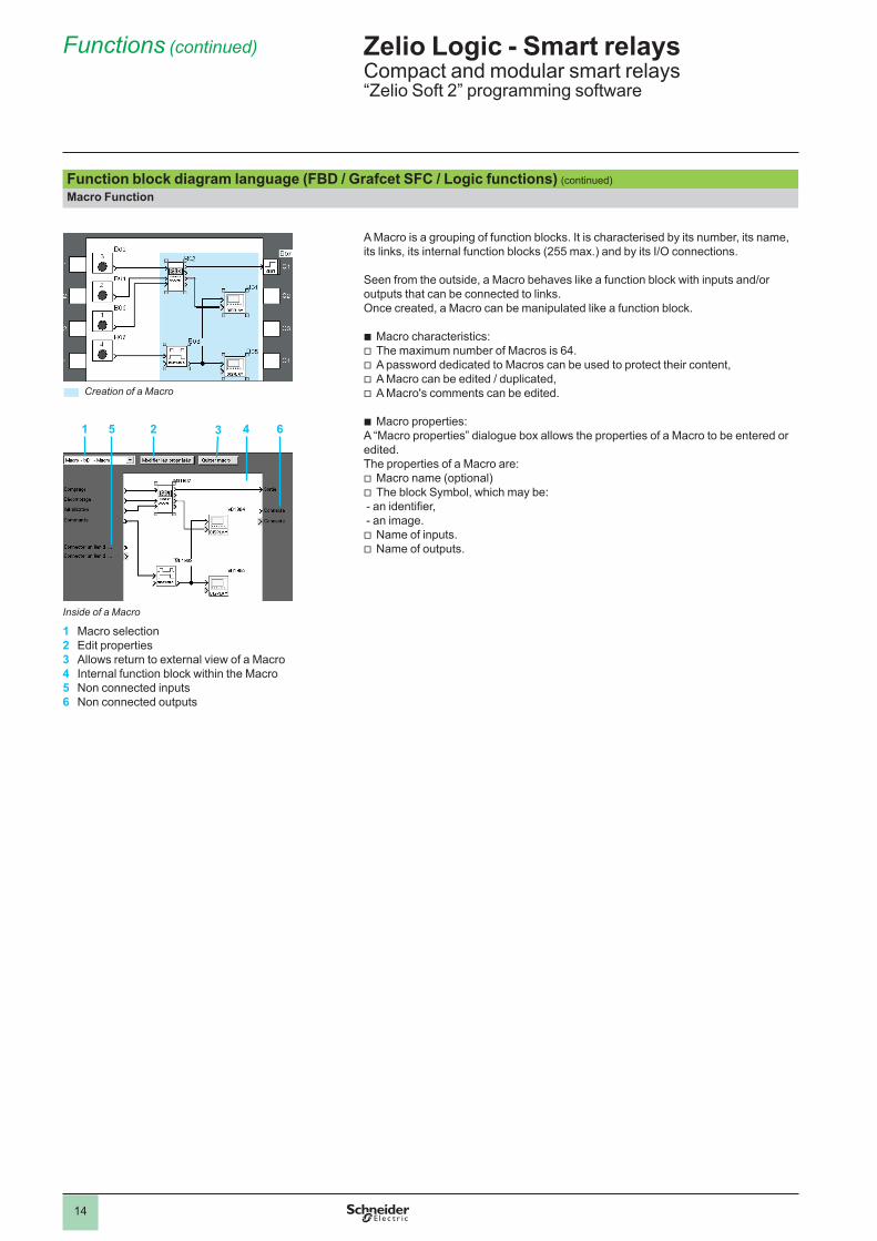
Function block diagram language (FBD / Grafcet SFC / Logic functions) (continued)Macro Function
A Macro is a grouping of function blocks. It is characterised by its number, its name, its links, its internal function blocks (255 max.) and by its I/O connections.
Seen from the outside, a Macro behaves like a function block with inputs and/or outputs that can be connected to links.Once created, a Macro can be manipulated like a function block.
b Macro characteristics:v The maximum number of Macros is 64.v A password dedicated to Macros can be used to protect their content,v A Macro can be edited / duplicated,v A Macro's comments can be edited. b Macro properties: A “Macro properties” dialogue box allows the properties of a Macro to be entered or edited. The properties of a Macro are:v Macro name (optional)v The block Symbol, which may be: - an identifier, - an image.v Name of inputs.v Name of outputs.
Creation of a Macro
Inside of a Macro
1 Macro selection2 Edit properties3 Allows return to external view of a Macro4 Internal function block within the Macro5 Non connected inputs6 Non connected outputs
1 5 2 3 4 6
Zelio Logic - Smart relaysCompact and modular smart relays“Zelio Soft 2” programming software
Functions (continued)
1
2
3
4
5
6
7
8
9
10
15
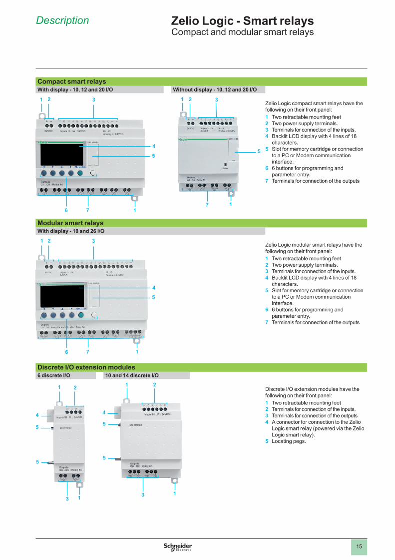
Compact smart relaysWith display - 10, 12 and 20 I/O Without display - 10, 12 and 20 I/O
Zelio Logic compact smart relays have the following on their front panel:1 Two retractable mounting feet2 Two power supply terminals.3 Terminals for connection of the inputs.4 Backlit LCD display with 4 lines of 18
characters.5 Slot for memory cartridge or connection
to a PC or Modem communication interface.
6 6 buttons for programming and parameter entry.
7 Terminals for connection of the outputs
Modular smart relaysWith display - 10 and 26 I/O
Zelio Logic modular smart relays have the following on their front panel:1 Two retractable mounting feet2 Two power supply terminals.3 Terminals for connection of the inputs.4 Backlit LCD display with 4 lines of 18
characters.5 Slot for memory cartridge or connection
to a PC or Modem communication interface.
6 6 buttons for programming and parameter entry.
7 Terminals for connection of the outputs
Discrete I/O extension modules6 discrete I/O 10 and 14 discrete I/O
Discrete I/O extension modules have the following on their front panel:1 Two retractable mounting feet2 Terminals for connection of the inputs.3 Terminals for connection of the outputs4 A connector for connection to the Zelio
Logic smart relay (powered via the Zelio Logic smart relay).
5 Locating pegs.
1
5
7
1 2 3
1
1
5
5
4
3
2
7
1
4
1
5
6
32
1
1
5
5
4
3
2
1
4
1
5
2
7
3
6
Zelio Logic - Smart relaysCompact and modular smart relays
Description
1
2
3
4
5
6
7
8
9
10
16
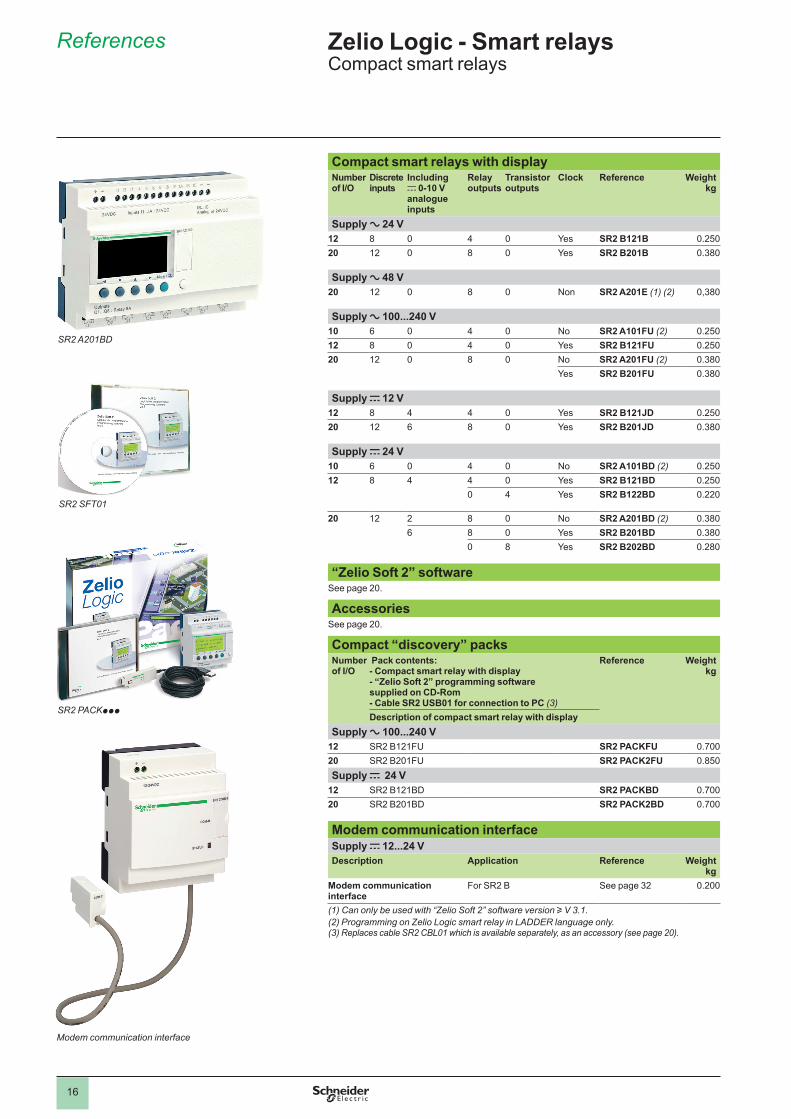
Compact smart relays with displayNumber of I/O
Discrete inputs
Including c 0-10 V analogue inputs
Relay outputs
Transistor outputs
Clock Reference Weight kg
Supply a 24 V12 8 0 4 0 Yes SR2 B121B 0.25020 12 0 8 0 Yes SR2 B201B 0.380
Supply a 48 V20 12 0 8 0 Non SR2 A201E (1) (2) 0,380
Supply a 100...240 V10 6 0 4 0 No SR2 A101FU (2) 0.25012 8 0 4 0 Yes SR2 B121FU 0.25020 12 0 8 0 No SR2 A201FU (2) 0.380
Yes SR2 B201FU 0.380
Supply c 12 V12 8 4 4 0 Yes SR2 B121JD 0.25020 12 6 8 0 Yes SR2 B201JD 0.380
Supply c 24 V10 6 0 4 0 No SR2 A101BD (2) 0.25012 8 4 4 0 Yes SR2 B121BD 0.250
0 4 Yes SR2 B122BD 0.220
20 12 2 8 0 No SR2 A201BD (2) 0.3806 8 0 Yes SR2 B201BD 0.380
0 8 Yes SR2 B202BD 0.280
“Zelio Soft 2” softwareSee page 20.
AccessoriesSee page 20.
Compact “discovery” packsNumber of I/O
Pack contents:- Compact smart relay with display- “Zelio Soft 2” programming software supplied on CD-Rom- Cable SR2 USB01 for connection to PC (3)
Reference Weightkg
Description of compact smart relay with displaySupply a 100...240 V
12 SR2 B121FU SR2 PACKFU 0.70020 SR2 B201FU SR2 PACK2FU 0.850Supply c 24 V
12 SR2 B121BD SR2 PACKBD 0.70020 SR2 B201BD SR2 PACK2BD 0.700
Modem communication interfaceSupply c 12...24 VDescription Application Reference Weight
kgModem communication interface
For SR2 B See page 32 0.200
(1) Can only be used with “Zelio Soft 2” software version u V 3.1.(2) Programming on Zelio Logic smart relay in LADDER language only.(3) Replaces cable SR2 CBL01 which is available separately, as an accessory (see page 20).
SR2 A201BD
SR2 SFT01
SR2 PACKppp
Modem communication interface
Zelio Logic - Smart relaysCompact smart relays
References
1
2
3
4
5
6
7
8
9
10
17
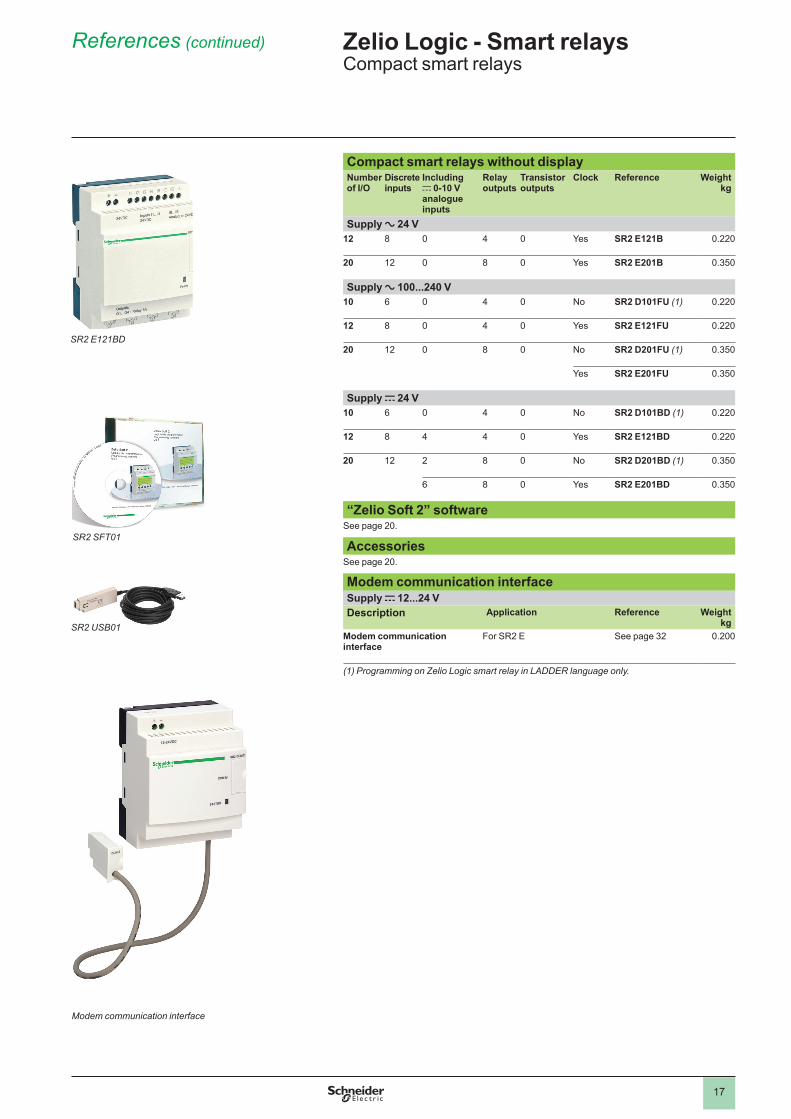
Zelio Logic - Smart relaysCompact smart relays
References (continued)
Compact smart relays without displayNumber of I/O
Discrete inputs
Including c 0-10 V analogue inputs
Relay outputs
Transistor outputs
Clock Reference Weight kg
Supply a 24 V12 8 0 4 0 Yes SR2 E121B 0.220
20 12 0 8 0 Yes SR2 E201B 0.350
Supply a 100...240 V10 6 0 4 0 No SR2 D101FU (1) 0.220
12 8 0 4 0 Yes SR2 E121FU 0.220
20 12 0 8 0 No SR2 D201FU (1) 0.350
Yes SR2 E201FU 0.350
Supply c 24 V10 6 0 4 0 No SR2 D101BD (1) 0.220
12 8 4 4 0 Yes SR2 E121BD 0.220
20 12 2 8 0 No SR2 D201BD (1) 0.350
6 8 0 Yes SR2 E201BD 0.350
“Zelio Soft 2” softwareSee page 20.
AccessoriesSee page 20.
Modem communication interfaceSupply c 12...24 VDescription Application Reference Weight
kgModem communication interface
For SR2 E See page 32 0.200
(1) Programming on Zelio Logic smart relay in LADDER language only.
SR2 SFT01
Modem communication interface
SR2 E121BD
SR2 USB01
1
2
3
4
5
6
7
8
9
10
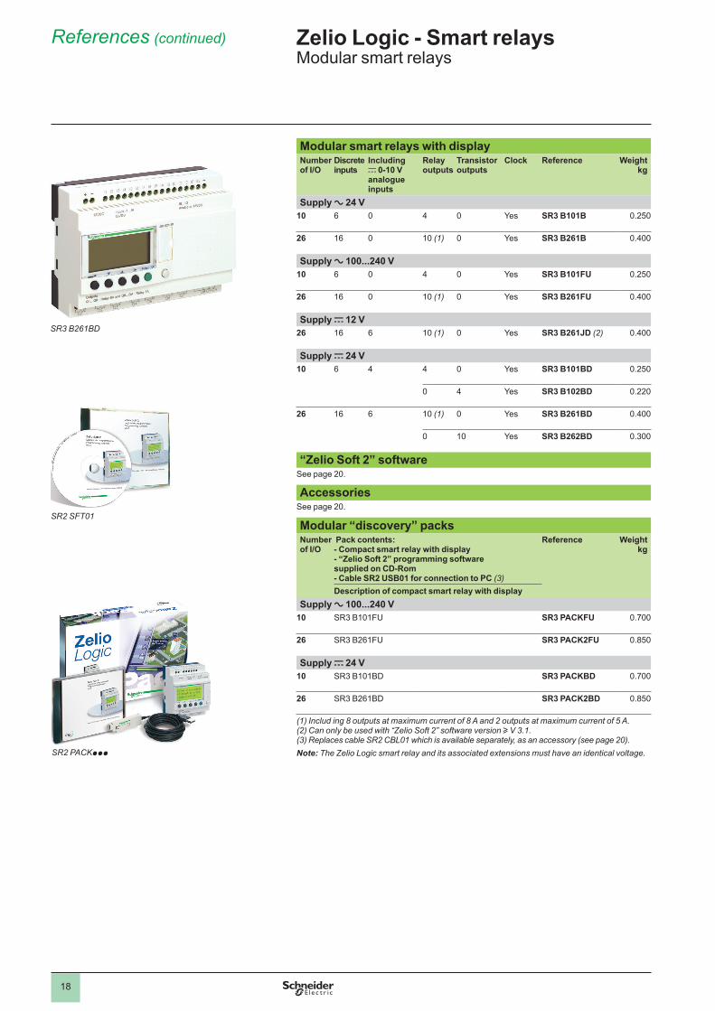
18
Modular smart relays with displayNumber of I/O
Discrete inputs
Including c 0-10 V analogue inputs
Relay outputs
Transistor outputs
Clock Reference Weight kg
Supply a 24 V10 6 0 4 0 Yes SR3 B101B 0.250
26 16 0 10 (1) 0 Yes SR3 B261B 0.400
Supply a 100...240 V10 6 0 4 0 Yes SR3 B101FU 0.250
26 16 0 10 (1) 0 Yes SR3 B261FU 0.400
Supply c 12 V26 16 6 10 (1) 0 Yes SR3 B261JD (2) 0.400
Supply c 24 V10 6 4 4 0 Yes SR3 B101BD 0.250
0 4 Yes SR3 B102BD 0.220
26 16 6 10 (1) 0 Yes SR3 B261BD 0.400
0 10 Yes SR3 B262BD 0.300
“Zelio Soft 2” softwareSee page 20.
AccessoriesSee page 20.
Modular “discovery” packsNumber of I/O
Pack contents:- Compact smart relay with display- “Zelio Soft 2” programming software supplied on CD-Rom- Cable SR2 USB01 for connection to PC (3)
Reference Weightkg
Description of compact smart relay with displaySupply a 100...240 V
10 SR3 B101FU SR3 PACKFU 0.700
26 SR3 B261FU SR3 PACK2FU 0.850
Supply c 24 V10 SR3 B101BD SR3 PACKBD 0.700
26 SR3 B261BD SR3 PACK2BD 0.850
(1) Includ ing 8 outputs at maximum current of 8 A and 2 outputs at maximum current of 5 A.(2) Can only be used with “Zelio Soft 2” software version u V 3.1.(3) Replaces cable SR2 CBL01 which is available separately, as an accessory (see page 20). Note: The Zelio Logic smart relay and its associated extensions must have an identical voltage.
SR2 SFT01
SR2 PACKppp
SR3 B261BD
Zelio Logic - Smart relaysModular smart relays
References (continued)
1
2
3
4
5
6
7
8
9
10
19
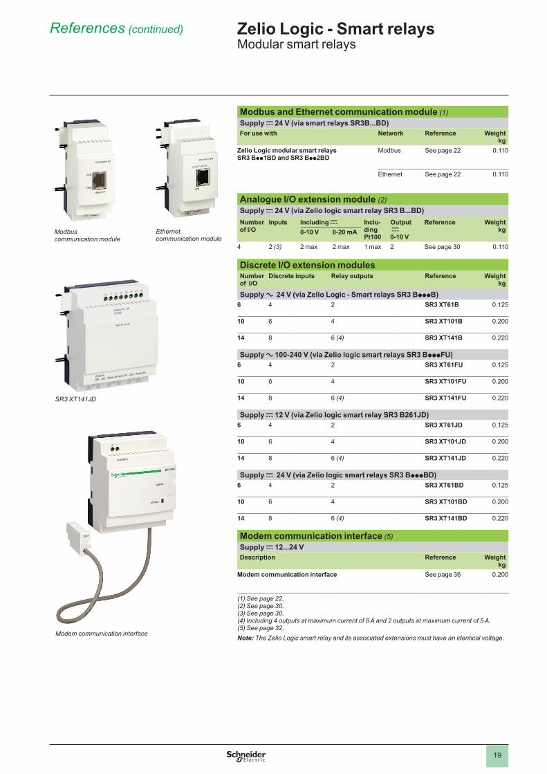
References (continued) Zelio Logic - Smart relaysModular smart relays
Modbus and Ethernet communication module (1) Supply c 24 V (via smart relays SR3B...BD)For use with Network Reference Weight
kgZelio Logic modular smart relays SR3 Bpp1BD and SR3 Bpp2BD
Modbus See page 22 0.110
Ethernet See page 22 0.110
Analogue I/O extension module (2)Supply c 24 V (via Zelio logic smart relay SR3 B...BD)Number of I/O
Inputs Including c Inclu-ding Pt100
Output c0-10 V
Reference Weightkg0-10 V 0-20 mA
4 2 (3) 2 max 2 max 1 max 2 See page 30 0.110
Discrete I/O extension modules Numberof I/O
Discrete inputs Relay outputs Reference Weightkg
Supply a 24 V (via Zelio Logic - Smart relays SR3 BpppB)6 4 2 SR3 XT61B 0.125
10 6 4 SR3 XT101B 0.200
14 8 6 (4) SR3 XT141B 0.220
Supply a 100-240 V (via Zelio logic smart relays SR3 BpppFU)6 4 2 SR3 XT61FU 0.125
10 6 4 SR3 XT101FU 0.200
14 8 6 (4) SR3 XT141FU 0.220
Supply c 12 V (via Zelio logic smart relay SR3 B261JD)6 4 2 SR3 XT61JD 0.125
10 6 4 SR3 XT101JD 0.200
14 8 6 (4) SR3 XT141JD 0.220
Supply c 24 V (via Zelio logic smart relays SR3 BpppBD)6 4 2 SR3 XT61BD 0.125
10 6 4 SR3 XT101BD 0.200
14 8 6 (4) SR3 XT141BD 0.220
Modem communication interface (5)Supply c 12...24 VDescription Reference Weight
kgModem communication interface See page 36 0.200
(1) See page 22.(2) See page 30.(3) See page 30.(4) Including 4 outputs at maximum current of 8 A and 2 outputs at maximum current of 5 A.(5) See page 32.Note: The Zelio Logic smart relay and its associated extensions must have an identical voltage.
SR3 XT141JD
Ethernetcommunication module
Modbuscommunication module
Modem communication interface
1
2
3
4
5
6
7
8
9
10
20
Converters forthermocouples
Regulated switch modepower supply
SR2 BTC01
SR2 MEM02
SR2 USB01
SR2 SFT01
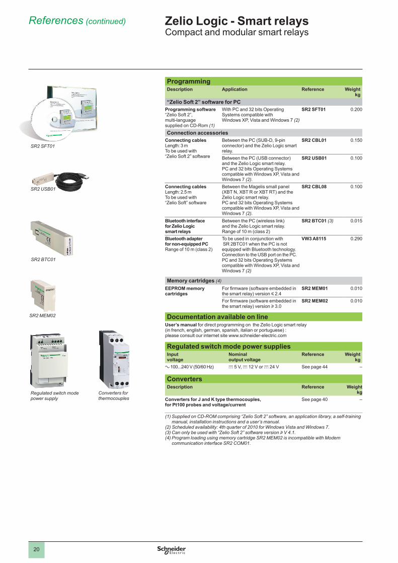
References (continued) Zelio Logic - Smart relaysCompact and modular smart relays
ProgrammingDescription Application Reference Weight
kg“Zelio Soft 2” software for PC
Programming software “Zelio Soft 2”,multi-language supplied on CD-Rom (1)
With PC and 32 bits OperatingSystems compatible withWindows XP, Vista and Windows 7 (2)
SR2 SFT01 0.200
Connection accessoriesConnecting cablesLength: 3 mTo be used with “Zelio Soft 2” software
Between the PC (SUB-D, 9-pin connector) and the Zelio Logic smart relay.
SR2 CBL01 0.150
Between the PC (USB connector)and the Zelio Logic smart relay.PC and 32 bits Operating Systems compatible with Windows XP, Vista and Windows 7 (2).
SR2 USB01 0.100
Connecting cablesLength: 2.5 mTo be used with “Zelio Soft” software
Between the Magelis small panel (XBT N, XBT R or XBT RT) and the Zelio Logic smart relay.PC and 32 bits Operating Systems compatible with Windows XP, Vista and Windows 7 (2).
SR2 CBL08 0.100
Bluetooth interface for Zelio Logic smart relays
Between the PC (wireless link) and the Zelio Logic smart relay. Range of 10 m (class 2)
SR2 BTC01 (3) 0.015
Bluetooth adapter for non-equipped PCRange of 10 m (class 2)
To be used in conjunction with SR 2BTC01 when the PC is not equipped with Bluetooth technology. Connection to the USB port on the PC. PC and 32 bits Operating Systems compatible with Windows XP, Vista and Windows 7 (2)
VW3 A8115 0.290
Memory cartridges (4)EEPROM memory cartridges
For firmware (software embedded in the smart relay) version y 2.4
SR2 MEM01 0.010
For firmware (software embedded in the smart relay) version u 3.0
SR2 MEM02 0.010
Documentation available on lineUser’s manual for direct programming on the Zelio Logic smart relay(in french, english, german, spanish, italian or portuguese) :please consult our internet site www.schneider-electric.com
Regulated switch mode power suppliesInput voltage
Nominal output voltage
Reference Weightkg
a 100...240 V (50/60 Hz) c 5 V, c 12 V or c 24 V See page 44 –
Converters Description Reference Weight
kgConverters for J and K type thermocouples,for Pt100 probes and voltage/current
See page 40 –
(1) Supplied on CD-ROM comprising “Zelio Soft 2” software, an application library, a self-training manual, installation instructions and a user’s manual.
(2) Scheduled availability: 4th quarter of 2010 for Windows Vista and Windows 7.(3) Can only be used with “Zelio Soft 2” software version u V 4.1.(4) Program loading using memory cartridge SR2 MEM02 is incompatible with Modem
communication interface SR2 COM01.
1
2
3
4
5
6
7
8
9
10
21
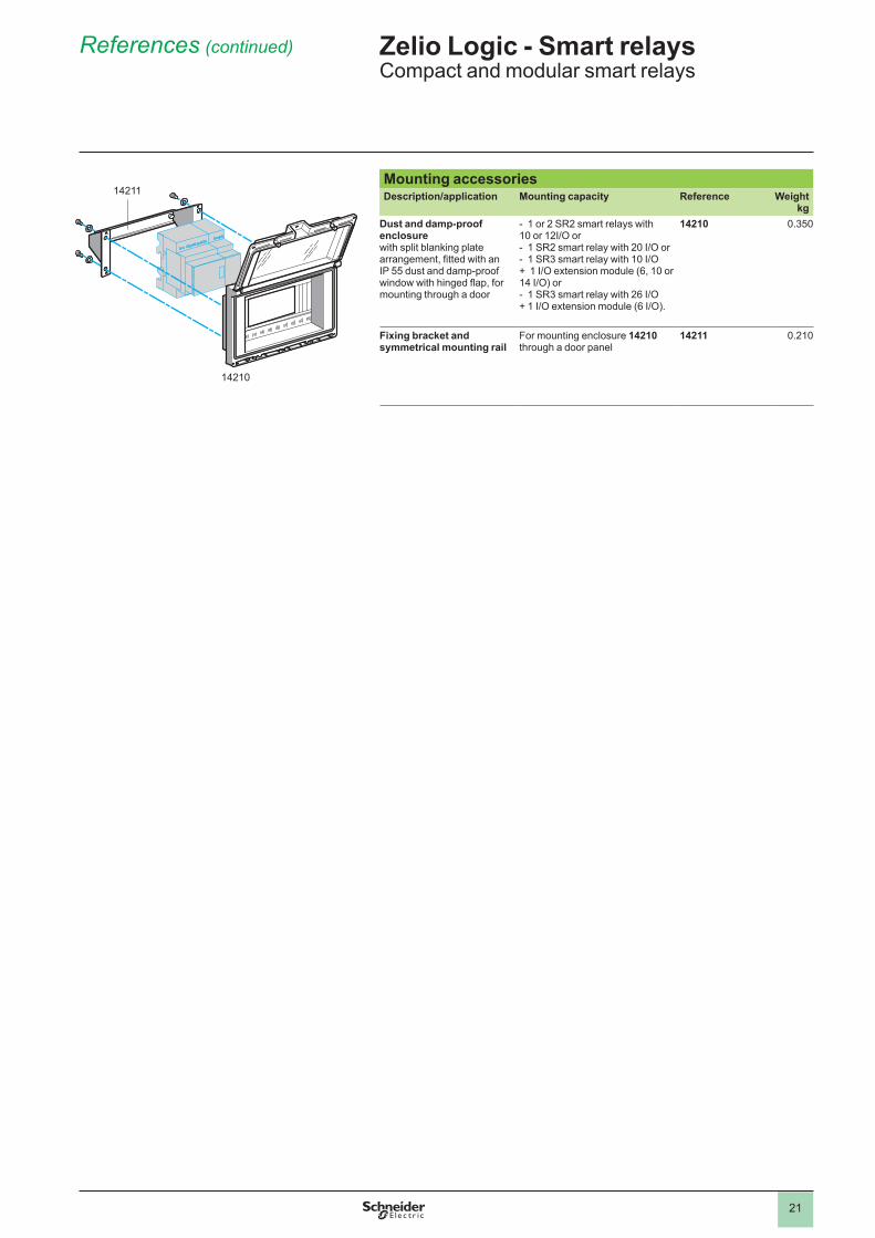
Mounting accessoriesDescription/application Mounting capacity Reference Weight
kgDust and damp-proof enclosure with split blanking plate arrangement, fitted with an IP 55 dust and damp-proof window with hinged flap, for mounting through a door
- 1 or 2 SR2 smart relays with 10 or 12I/O or- 1 SR2 smart relay with 20 I/O or- 1 SR3 smart relay with 10 I/O + 1 I/O extension module (6, 10 or 14 I/O) or- 1 SR3 smart relay with 26 I/O + 1 I/O extension module (6 I/O).
14210 0.350
Fixing bracket and symmetrical mounting rail
For mounting enclosure 14210 through a door panel
14211 0.210
14210
14211
References (continued) Zelio Logic - Smart relaysCompact and modular smart relays
1
2
3
4
5
6
7
8
9
10
22
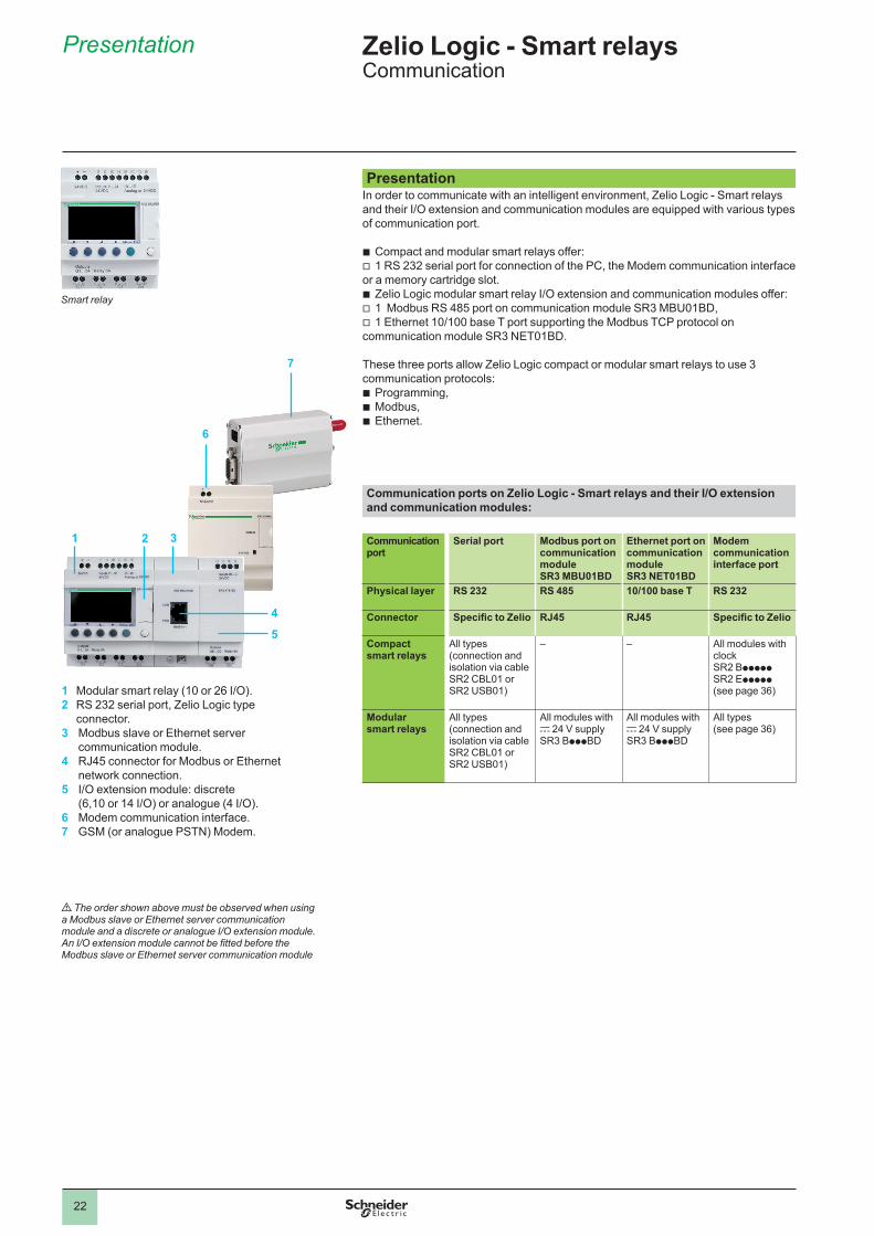
Presentation In order to communicate with an intelligent environment, Zelio Logic - Smart relays and their I/O extension and communication modules are equipped with various types of communication port.
bb Compact and modular smart relays offer:bv 1 RS 232 serial port for connection of the PC, the Modem communication interface
or a memory cartridge slot.bb Zelio Logic modular smart relay I/O extension and communication modules offer:bv 1 Modbus RS 485 port on communication module SR3 MBU01BD,bv 1 Ethernet 10/100 base T port supporting the Modbus TCP protocol on
communication module SR3 NET01BD.
These three ports allow Zelio Logic compact or modular smart relays to use 3 communication protocols:bb Programming,bb Modbus,bb Ethernet.
Communication ports on Zelio Logic - Smart relays and their I/O extension and communication modules:
Communication port
Serial port Modbus port on communication module SR3 MBU01BD
Ethernet port on communication module SR3 NET01BD
Modem communication interface port
Physical layer RS 232 RS 485 10/100 base T RS 232
Connector Specific to Zelio RJ45 RJ45 Specific to Zelio
Compact smart relays
All types (connection and isolation via cable SR2 CBL01 or SR2 USB01)
– – All modules with clockSR2 BpppppSR2 Eppppp(see page 36)
Modular smart relays
All types (connection and isolation via cable SR2 CBL01 or SR2 USB01)
All modules with c 24 V supplySR3 BpppBD
All modules with c 24 V supplySR3 BpppBD
All types(see page 36)
Presentation
7
6
1 3
1 Modular smart relay (10 or 26 I/O).2 RS 232 serial port, Zelio Logic type
connector.3 Modbus slave or Ethernet server
communication module.4 RJ45 connector for Modbus or Ethernet
network connection.5 I/O extension module: discrete
(6,10 or 14 I/O) or analogue (4 I/O).6 Modem communication interface.7 GSM (or analogue PSTN) Modem.
d The order shown above must be observed when usinga Modbus slave or Ethernet server communicationmodule and a discrete or analogue I/O extension module.An I/O extension module cannot be fitted before theModbus slave or Ethernet server communication module
2
4
5
Smart relay
Zelio Logic - Smart relaysCommunication
1
2
3
4
5
6
7
8
9
10
23
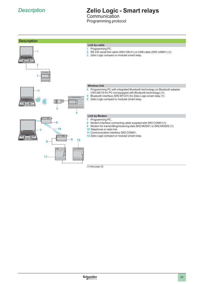
Description Link by cable
1 Programming PC.2 RS 232 serial link cable (SR2 CBL01) or USB cable (SR2 USB01) (1). 3 Zelio Logic compact or modular smart relay.
Wireless link4 Programming PC with integrated Bluetooth technology (or Bluetooth adapter
VW3 A8115 for PC not equipped with Bluetooth technology) (1).5 Bluetooth interface (SR2 BTC01) for Zelio Logic smart relay (1).6 Zelio Logic compact or modular smart relay.
Link by Modem7 Programming PC.8 Modem interface connecting cable supplied with SR2 COM01(1).9 Modem for transmitting/receiving data SR2 MOD01 or SR2 MOD02 (1).10 Telephone or radio link.11 Communication interface SR2 COM01.12 Zelio Logic compact or modular smart relay.
(1) See page 20.
1
3
2
4
56
7
9
10
9 128
11
Description Zelio Logic - Smart relaysCommunicationProgramming protocol
1
2
3
4
5
6
7
8
9
10
24
PresentationThe Modbus communication protocol is of the master/slave type.Two exchange methods are possible:bb Request/reply: bv The request from the master is addressed to a specific slave. bv The master waits for the reply to be returned by the slave polled.bb Distribution: bv The master distributes a request to all the slave stations on the bus.
These stations execute the instruction without sending a reply.
Zelio Logic modular smart relays are connected to the Modbus network via the Modbus slave communication module. This module is a slave that is not electrically isolated. The Modbus slave communication module must be connected to an SR3 BpppBD modular smart relay, with a c 24 V supply.
ConfigurationThe Modbus network slave communication module can be configured:bb independently, using the buttons on the smart relay (1).bb on a PC, using “Zelio Soft 2” software, see page 10.
When using a PC, programming can be performed either in LADDER language or in function block diagram (FBD) language, see page 12.
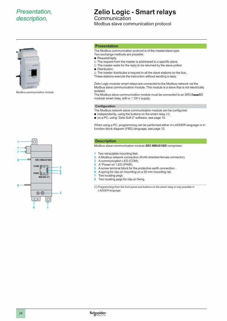
Description Modbus slave communication module SR3 MBU01BD comprises:
1 Two retractable mounting feet.2 A Modbus network connection (RJ45 shielded female connector). 3 A communication LED (COM).4 A “Power on” LED (PWR).5 A screw terminal block for the protective earth connection.6 A spring for clip-on mounting on a 35 mm mounting rail.7 Two locating pegs.8 Two locating pegs for clip-on fixing.
(1) Programming from the front panel and buttons on the smart relay is only possible in LADDER language.
Presentation, description,
COM
SR3 MBU01BD
MB485-V1PWR
6 1
8
8
2
5
3
4
1
77
Modbus communication module
Zelio Logic - Smart relaysCommunicationModbus slave communication protocol
1
2
3
4
5
6
7
8
9
10
25
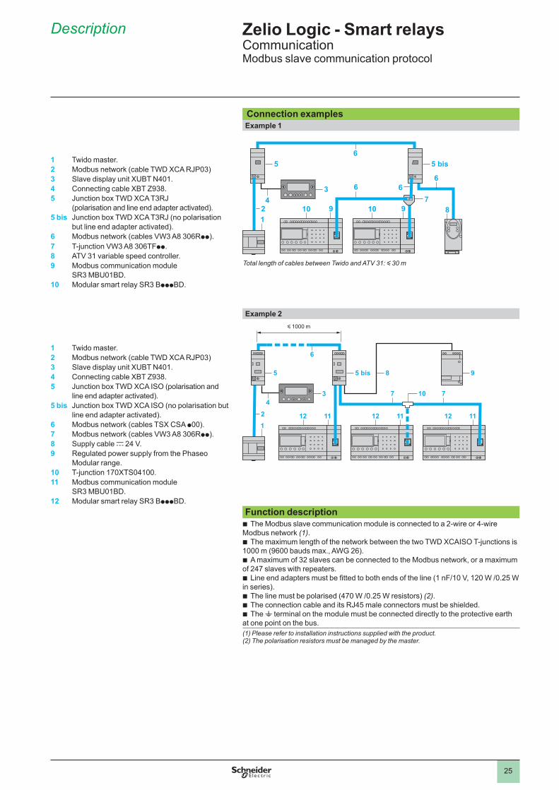
Connection examples Example 1
Total length of cables between Twido and ATV 31: y 30 m
1 Twido master.2 Modbus network (cable TWD XCA RJP03)3 Slave display unit XUBT N401.4 Connecting cable XBT Z938.5 Junction box TWD XCA T3RJ
(polarisation and line end adapter activated).5 bis Junction box TWD XCA T3RJ (no polarisation
but line end adapter activated).6 Modbus network (cables VW3 A8 306Rpp).7 T-junction VW3 A8 306TFpp.8 ATV 31 variable speed controller.9 Modbus communication module
SR3 MBU01BD.10 Modular smart relay SR3 BpppBD.
Example 2y 1000 m
1 Twido master.2 Modbus network (cable TWD XCA RJP03)3 Slave display unit XUBT N401.4 Connecting cable XBT Z938.5 Junction box TWD XCA ISO (polarisation and
line end adapter activated).5 bis Junction box TWD XCA ISO (no polarisation but
line end adapter activated).6 Modbus network (cables TSX CSA p00).7 Modbus network (cables VW3 A8 306Rpp).8 Supply cable c 24 V.9 Regulated power supply from the Phaseo
Modular range.10 T-junction 170XTS04100.11 Modbus communication module
SR3 MBU01BD.12 Modular smart relay SR3 BpppBD.
Function descriptionbb The Modbus slave communication module is connected to a 2-wire or 4-wire
Modbus network (1).bb The maximum length of the network between the two TWD XCAISO T-junctions is
1000 m (9600 bauds max., AWG 26).bb A maximum of 32 slaves can be connected to the Modbus network, or a maximum
of 247 slaves with repeaters.bb Line end adapters must be fitted to both ends of the line (1 nF/10 V, 120 W /0.25 W
in series).bb The line must be polarised (470 W /0.25 W resistors) (2).bb The connection cable and its RJ45 male connectors must be shielded.bb The t terminal on the module must be connected directly to the protective earth
at one point on the bus.(1) Please refer to installation instructions supplied with the product.(2) The polarisation resistors must be managed by the master.
Description Zelio Logic - Smart relaysCommunicationModbus slave communication protocol
1
2
3
4
5
6
7
8
9
10
26
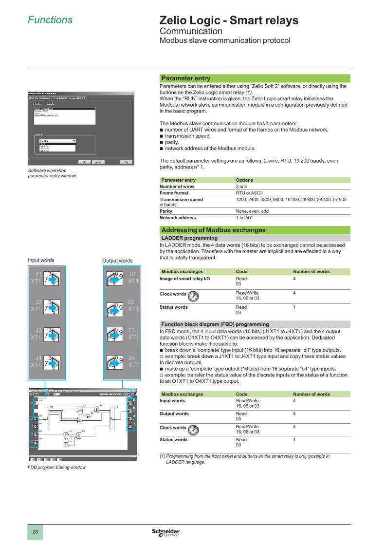
Parameter entryParameters can be entered either using “Zelio Soft 2” software, or directly using the buttons on the Zelio Logic smart relay (1).When the “RUN” instruction is given, the Zelio Logic smart relay initialises the Modbus network slave communication module in a configuration previously defined in the basic program.
The Modbus slave communication module has 4 parameters:bb number of UART wires and format of the frames on the Modbus network,bb transmission speed,bb parity,bb network address of the Modbus module.
The default parameter settings are as follows: 2-wire, RTU, 19 200 bauds, even parity, address n° 1.
Parameter entry OptionsNumber of wires 2 or 4Frame format RTU or ASCIITransmission speedin bauds
1200, 2400, 4800, 9600, 19 200, 28 800, 38 400, 57 600
Parity None, even, oddNetwork address 1 to 247
Addressing of Modbus exchangesLADDER programming
In LADDER mode, the 4 data words (16 bits) to be exchanged cannot be accessed by the application. Transfers with the master are implicit and are effected in a way that is totally transparent.
Modbus exchanges Code Number of words
Image of smart relay I/O Read03
4
Clock words Read/Write16, 06 or 03
4
Status words Read03
1
Function block diagram (FBD) programming In FBD mode, the 4 input data words (16 bits) (J1XT1 to J4XT1) and the 4 output
data words (O1XT1 to O4XT1) can be accessed by the application. Dedicated function blocks make it possible to:bb break down a ‘complete’ type input (16 bits) into 16 separate “bit” type outputs.bv example: break down a J1XT1 to J4XT1 type input and copy these status values
to discrete outputs.bb make up a ‘complete’ type output (16 bits) from 16 separate “bit” type inputs.bv example: transfer the status value of the discrete inputs or the status of a function
to an O1XT1 to O4XT1 type output.
Modbus exchanges Code Number of wordsInput words Read/Write
16, 06 or 034
Output words Read03
4
Clock words Read/Write16, 06 or 03
4
Status words
Read03
1
(1) Programming from the front panel and buttons on the smart relay is only possible in LADDER language.
Software workshopparameter entry window
J1XT1
J2XT1
J3XT1
J4XT1
37
2
37
2
37
2
37
2
01 XT1
02 XT1
03 XT1
04 XT1
0 934
0 934
0 934
0 934
Input words Output words
FDB program Editing window
Zelio Logic - Smart relaysCommunicationModbus slave communication protocol
Functions
1
2
3
4
5
6
7
8
9
10
27
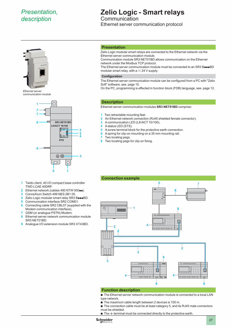
PresentationZelio Logic modular smart relays are connected to the Ethernet network via the Ethernet server communication module.Communication module SR3 NET01BD allows communication on the Ethernet network under the Modbus TCP protocol.The Ethernet server communication module must be connected to an SR3 BpppBD modular smart relay, with a c 24 V supply.
ConfigurationThe Ethernet server communication module can be configured from a PC with "Zelio Soft" software, see page 10.On the PC, programming is effected in function block (FDB) language, see page 12.
LK/ACT 10/100SR3 NET01BD
STS
6 1
8
8
2
5
3
4
1
77
DescriptionEthernet server communication modules SR3 NET01BD comprise:
1 Two retractable mounting feet.2 An Ethernet network connection (RJ45 shielded female connector). 3 A communication LED (LK/ACT 10/100).4 A status LED (STS).5 A screw terminal block for the protective earth connection.6 A spring for clip-on mounting on a 35 mm mounting rail.7 Two locating pegs.8 Two locating pegs for clip-on fixing.
Connection example1 Twido client, 40 I/O compact base controller
TWD LCAE 40DRF.2 Ethernet network (cables 490 NTW 000pp).3 ConneXium Switch 499 NES 2B1 00.4 Zelio Logic modular smart relay SR3 BpppBD.5 Communication interface SR2 COM01.6 Connecting cable SR2 CBL07 (supplied with the
Modem communication interface). 7 GSM (or analogue PSTN) Modem.8 Ethernet server network communication module
SR3 NET01BD.9 Analogue I/O extension module SR3 XT43BD.
Function descriptionbb The Ethernet server network communication module is connected to a local LAN
type network.bb The maximum cable length between 2 devices is 100 m.bb The connection cable must be at least category 5, and its RJ45 male connectors
must be shielded.bb The t terminal must be connected directly to the protective earth.
Ethernet server communication module
Presentation, description
Zelio Logic - Smart relaysCommunicationEthernet server communication protocol
1
2
3
4
5
6
7
8
9
10
28
Input words Output words
FDB program Editing window
Zelio Logic - Smart relaysCommunicationEthernet server network communication module
Functions
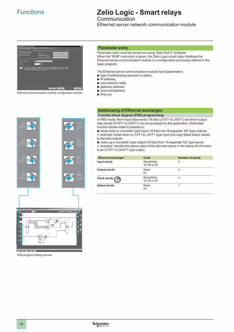
Parameter entryParameter entry must be carried out using “Zelio Soft 2” software.When the “RUN” instruction is given, the Zelio Logic smart relay initialises the Ethernet server communication module in a configuration previously defined in the basic program.
The Ethernet server communication module has 6 parameters:bb type of addressing (dynamic or static). bb IP address,bb sub-network mask,bb gateway address,bb reserved address,bb time out.
Addressing of Ethernet exchangesFunction block diagram (FBD) programming
In FBD mode, the 4 input data words (16 bits) (J1XT1 to J4XT1) and the 4 output data words (O1XT1 to O4XT1) can be accessed by the application. Dedicated function blocks make it possible to:bb break down a ‘complete’ type input (16 bits) into 16 separate “bit” type outputs.bv example: break down a J1XT1 to J4XT1 type input and copy these status values
to discrete outputs.bb make up a ‘complete’ type output (16 bits) from 16 separate “bit” type inputs.bv example: transfer the status value of the discrete inputs or the status of a function
to an O1XT1 to O4XT1 type output.
Ethernet exchanges Code Number of wordsInput words Read/Write
16, 06 or 034
Output words Read03
4
Clock words Read/Write16, 06 or 03
4
Status words Read03
1
Ethernet communication module configuration window
J1XT1
J2XT1
J3XT1
J4XT1
37
2
37
2
37
2
37
2
01 XT1
02 XT1
03 XT1
04 XT1
0 934
0 934
0 934
0 934
1
2
3
4
5
6
7
8
9
10
29
Zelio Logic - Smart relaysCommunication
References
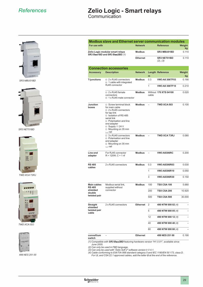
Modbus slave and Ethernet server communication modules For use with Network Reference Weight
kgZelio Logic modular smart relays SR3 Bpp1BD and SR3 Bpp2BD (1)
Modbus SR3 MBU01BD 0.110
Ethernet SR3 NET01BD (2), (3)
0.110
Connection accessories Accessory Description Network Length Reference Weight
m kgT-junctions bv 2 x RJ45 connectors
bv 1 cable with integrated RJ45 connector
Modbus 0.3 VW3 A8 306TF03 0.190
1 VW3 A8 306TF10 0.210
bv 2 x RJ45 female connectorsbv 1 x RJ45 male connector
Modbus Without cable
170 XTS 04100 0.020
Junction boxes
bv Screw terminal block for main cablebv 2 x RJ45 connectors
for tap linkbv Isolation of RS 485
serial link bv Polarisation and line
end adapterbv Supply c 24 V bv Mounting on 35 mm
7 rail
Modbus – TWD XCA ISO 0.100
bv 3 x RJ45 connectorsbv Polarisation and line
end adapterbv Mounting on 35 mm
7 rail
Modbus – TWD XCA T3RJ 0.080
Line end adapter
For RJ45 connector R = 120W, C = 1 nf
Modbus – VW3 A8306RC 0.200
RS 485 cables
2 x RJ45 connectors Modbus 0.3 VW3 A8306R03 0.030
1 VW3 A8306R10 0.050
3 VW3 A8306R30 0.150
Main cables RS 485 shielded double twisted pair
Modbus serial link, supplied without connector
Modbus 100 TSX CSA 100 5.680
200 TSX CSA 200 10.920
500 TSX CSA 500 30.000
Straight shielded twisted pair cable
2 x RJ45 connectors Ethernet 2 490 NTW 000 02 (4) –
5 490 NTW 000 05 (4) –
12 490 NTW 000 12 (4) –
40 490 NTW 000 40 (4) –
80 490 NTW 000 80 (4) –
conneXium switch
– Ethernet 499 NES 251 00 0.190
(1) Compatible with SR3 Bpp2BD featuring hardware version “H1.0.01”, available since June 2005.
(2) Can only be used in FBD language.(3) Can only be used with "Zelio Soft 2" software version u V 4.1.(4) Cable conforming to EIA/TIA-568 standard category 5 and IEC 1180/EN 50 173, class D.
For UL and CSA 22.1 approved cables, add the letter U at the end of the reference.
TWD XCA T3RJ
TWD XCA ISO
499 NES 251 00
SR3 MBU01BD
SR3 NET01BD
1
2
3
4
5
6
7
8
9
10
30
Combination of modular smart relays with communication and I/O extension modules
d The order shown above must be observed when using a network communication module and an analogue I/O extension module.An I/O extension module cannot be fitted before the network communication module.
1 2
1 Modular smart relay (10 or 26 I/O)2 Modbus or Ethernet communication modules3 Analogue I/O extension module (4 I/O)
3
Analogue I/O extension modules
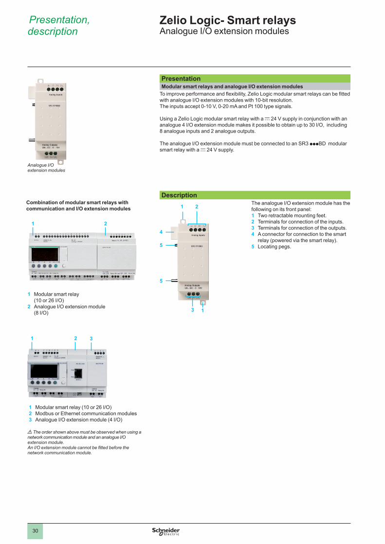
Presentation Modular smart relays and analogue I/O extension modules
To improve performance and flexibility, Zelio Logic modular smart relays can be fitted with analogue I/O extension modules with 10-bit resolution.The inputs accept 0-10 V, 0-20 mA and Pt 100 type signals.
Using a Zelio Logic modular smart relay with a c 24 V supply in conjunction with an analogue 4 I/O extension module makes it possible to obtain up to 30 I/O, including 8 analogue inputs and 2 analogue outputs.
The analogue I/O extension module must be connected to an SR3 pppBD modular smart relay with a c 24 V supply.
Description The analogue I/O extension module has the
following on its front panel:1 Two retractable mounting feet.2 Terminals for connection of the inputs.3 Terminals for connection of the outputs.4 A connector for connection to the smart
relay (powered via the smart relay).5 Locating pegs.
1 2
5
13
5
4
Presentation, description
Zelio Logic- Smart relays Analogue I/O extension modules
1 2
1 Modular smart relay(10 or 26 I/O)
2 Analogue I/O extension module (8 I/O)
1
2
3
4
5
6
7
8
9
10
31
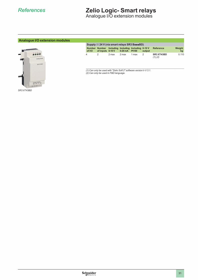
SR3 XT43BD
Analogue I/O extension modulesSupply c 24 V (via smart relays SR3 BpppBD)Number of I/O
Number of inputs
Including 0-10 V
Including 0-20 mA
Including Pt100
0-10 V output
Reference Weightkg
4 2 2 max 2 max 1 max 2 SR3 XT43BD (1),(2)
0.110
(1) Can only be used with "Zelio Soft 2" software version u V 3.1.(2) Can only be used in FBD language.
References Zelio Logic- Smart relays Analogue I/O extension modules
1
2
3
4
5
6
7
8
9
10
32
Presentation
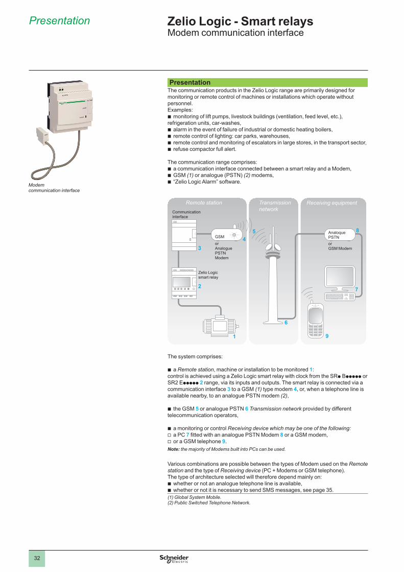
Presentation The communication products in the Zelio Logic range are primarily designed for monitoring or remote control of machines or installations which operate without personnel.Examples: b monitoring of lift pumps, livestock buildings (ventilation, feed level, etc.), refrigeration units, car-washes,b alarm in the event of failure of industrial or domestic heating boilers,b remote control of lighting: car parks, warehouses,b remote control and monitoring of escalators in large stores, in the transport sector,b refuse compactor full alert.
The communication range comprises:b a communication interface connected between a smart relay and a Modem,b GSM (1) or analogue (PSTN) (2) modems,b “Zelio Logic Alarm” software.
The system comprises:
b a Remote station, machine or installation to be monitored 1:control is achieved using a Zelio Logic smart relay with clock from the SRp Bppppp or SR2 Eppppp 2 range, via its inputs and outputs. The smart relay is connected via a communication interface 3 to a GSM (1) type modem 4, or, when a telephone line is available nearby, to an analogue PSTN modem (2),
b the GSM 5 or analogue PSTN 6 Transmission network provided by different telecommunication operators,
b a monitoring or control Receiving device which may be one of the following:v a PC 7 fitted with an analogue PSTN Modem 8 or a GSM modem,v or a GSM telephone 9. Note: the majority of Modems built into PCs can be used.
Various combinations are possible between the types of Modem used on the Remote station and the type of Receiving device (PC + Modems or GSM telephone). The type of architecture selected will therefore depend mainly on:b whether or not an analogue telephone line is available,b whether or not it is necessary to send SMS messages, see page 35. (1) Global System Mobile.(2) Public Switched Telephone Network.
1
2
34
5
7
8
9
6
Remote station Transmissionnetwork
Receiving equipmentCommunicationinterface
GSM
orAnaloguePSTNModem
Zelio Logicsmart relay
Analoque PSTNorGSM Modem
Zelio Logic - Smart relaysModem communication interface
Modemcommunication interface
1
2
3
4
5
6
7
8
9
10
33
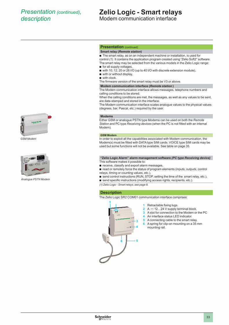
Presentation (continued)Smart relay (Remote station)
b The smart relay, as on an independent machine or installation, is used for control (1). It contains the application program created using “Zelio Soft2” software. The smart relay may be selected from the various models in the Zelio Logic range: b for all supply voltages,b with 10, 12, 20 or 26 I/O (up to 40 I/O with discrete extension module),b with or without display,b with clock.The firmware version of the smart relay must be V3 or above. Modem communication interface (Remote station )
The Modem communication interface allows messages, telephone numbers and calling conditions to be stored.When the calling conditions are met, the messages, as well as any values to be sent, are date-stamped and stored in the interface.The Modem communication interface scales analogue values to the physical values (degrees, bar, Pascal, etc.) required by the user. Modems
Either GSM or analogue PSTN type Modems can be used on both the Remote Station and PC type Receiving devices (when the PC is not fitted with an internal Modem). GSM Modem
In order to exploit all the capabilities associated with Modem communication, the Modem(s) must be fitted with DATA type SIM cards. VOICE type SIM cards may be used but some functions will not be available. See table on page 35.
“Zelio Logic Alarm” alarm management software (PC type Receiving device)
This software makes it possible to:b receive, classify and export alarm messages,b read or remotely force the status of program elements (inputs, outputs, control relays, timing or counting values, etc.),b send control instructions (RUN, STOP, setting the time of the smart relay, etc.),b send specific instructions (modifying access rights, recipients, etc.). (1) Zelio Logic - Smart relays, see page 8. Description
The Zelio Logic SR2 COM01 communication interface comprises:
123456
Retractable fixing lugs. A c 12…24 V supply terminal block.A slot for connection to the Modem or the PCAn interface status LED indicator.A connecting cable to the smart relay.A spring for clip-on mounting on a 35 mm mounting rail.
Presentation (continued), description
1
3
56
4
Analogue PSTN Modem
Zelio Logic - Smart relaysModem communication interface
GSM Modem
1
2
3
4
5
6
7
8
9
10
34
Functions
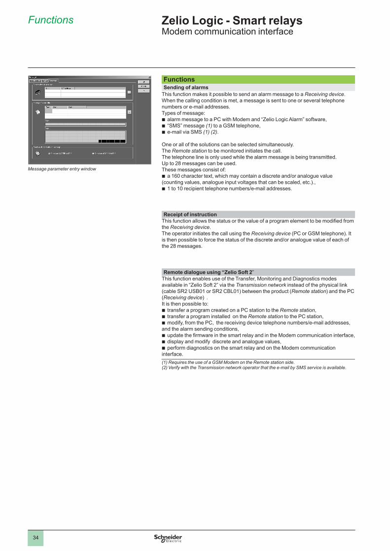
Functions Sending of alarms
This function makes it possible to send an alarm message to a Receiving device.When the calling condition is met, a message is sent to one or several telephone numbers or e-mail addresses.Types of message:b alarm message to a PC with Modem and “Zelio Logic Alarm” software,b “SMS” message (1) to a GSM telephone,b e-mail via SMS (1) (2).
One or all of the solutions can be selected simultaneously.The Remote station to be monitored initiates the call. The telephone line is only used while the alarm message is being transmitted. Up to 28 messages can be used.These messages consist of: b a 160 character text, which may contain a discrete and/or analogue value (counting values, analogue input voltages that can be scaled, etc.).,b 1 to 10 recipient telephone numbers/e-mail addresses.
Receipt of instruction
This function allows the status or the value of a program element to be modified from the Receiving device.The operator initiates the call using the Receiving device (PC or GSM telephone). It is then possible to force the status of the discrete and/or analogue value of each of the 28 messages.
Remote dialogue using “Zelio Soft 2”
This function enables use of the Transfer, Monitoring and Diagnostics modes available in “Zelio Soft 2” via the Transmission network instead of the physical link (cable SR2 USB01 or SR2 CBL01) between the product (Remote station) and the PC (Receiving device) .It is then possible to:b transfer a program created on a PC station to the Remote station,b transfer a program installed on the Remote station to the PC station,b modify, from the PC, the receiving device telephone numbers/e-mail addresses, and the alarm sending conditions,b update the firmware in the smart relay and in the Modem communication interface,b display and modify discrete and analogue values,b perform diagnostics on the smart relay and on the Modem communication interface. (1) Requires the use of a GSM Modem on the Remote station side.(2) Verify with the Transmission network operator that the e-mail by SMS service is available.
Message parameter entry window
Zelio Logic - Smart relaysModem communication interface
1
2
3
4
5
6
7
8
9
10
35
Smart relay
Functions (continued),setting up
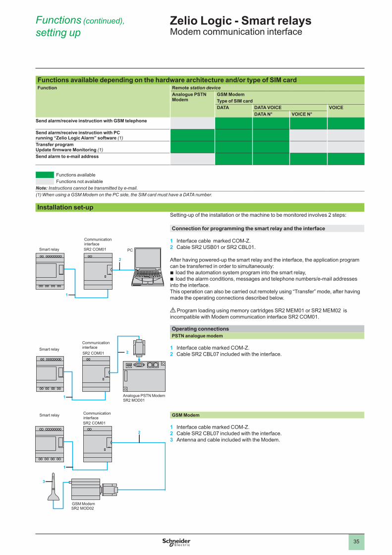
Functions available depending on the hardware architecture and/or type of SIM cardFunction Remote station device
Analogue PSTN Modem
GSM ModemType of SIM cardDATA DATA VOICE VOICE
DATA N° VOICE N°Send alarm/receive instruction with GSM telephone
Send alarm/receive instruction with PC running “Zelio Logic Alarm” software (1)Transfer programUpdate firmware Monitoring (1)Send alarm to e-mail address
Functions availableFunctions not available
Note: Instructions cannot be transmitted by e-mail.(1) When using a GSM Modem on the PC side, the SIM card must have a DATA number.
Installation set-upSetting-up of the installation or the machine to be monitored involves 2 steps: Connection for programming the smart relay and the interface
1 Interface cable marked COM-Z.2 Cable SR2 USB01 or SR2 CBL01.
After having powered-up the smart relay and the interface, the application program can be transferred in order to simultaneously: b load the automation system program into the smart relay, b load the alarm conditions, messages and telephone numbers/e-mail addresses into the interface.This operation can also be carried out remotely using “Transfer” mode, after having made the operating connections described below.
d Program loading using memory cartridges SR2 MEM01 or SR2 MEM02 is incompatible with Modem communication interface SR2 COM01.
Operating connections PSTN analogue modem
1 Interface cable marked COM-Z.2 Cable SR2 CBL07 included with the interface.
GSM Modem
1 Interface cable marked COM-Z.2 Cable SR2 CBL07 included with the interface.3 Antenna and cable included with the Modem.
SR2 COM01
1
2
Smart relay
Communicationinterface
PC
SR2 COM01
1
2
SR2 MOD01
Smart relayCommunicationinterface
Analogue PSTN Modem
Communicationinterface
GSM Modem
Smart relay
Zelio Logic - Smart relaysModem communication interface
1
2
3
4
5
6
7
8
9
10
36
References
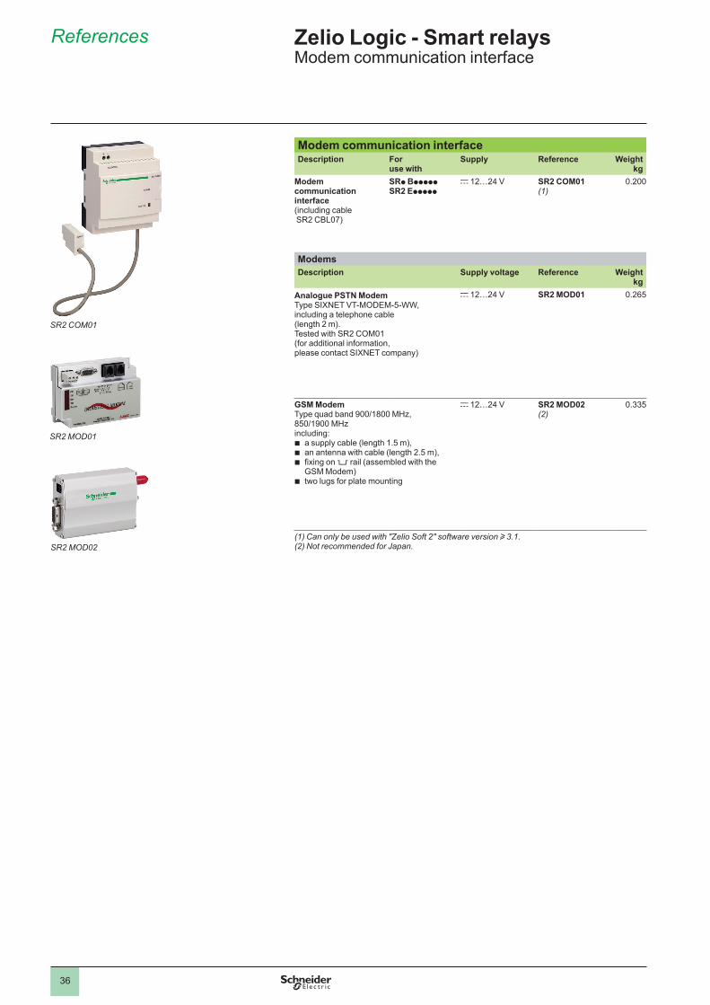
Modem communication interfaceDescription For
use withSupply Reference Weight
kgModem communication interface(including cable SR2 CBL07)
SRp BpppppSR2 Eppppp
c 12…24 V SR2 COM01(1)
0.200
ModemsDescription Supply voltage Reference Weight
kgAnalogue PSTN Modem Type SIXNET VT-MODEM-5-WW,including a telephone cable (length 2 m).Tested with SR2 COM01(for additional information, please contact SIXNET company)
c 12…24 V SR2 MOD01 0.265
GSM ModemType quad band 900/1800 MHz, 850/1900 MHzincluding:b a supply cable (length 1.5 m), b an antenna with cable (length 2.5 m),b fixing on 5 rail (assembled with the
GSM Modem)b two lugs for plate mounting
c 12…24 V SR2 MOD02(2)
0.335
(1) Can only be used with "Zelio Soft 2" software version u 3.1.(2) Not recommended for Japan.
SR2 COM01
SR2 MOD01
SR2 MOD02
Zelio Logic - Smart relaysModem communication interface
1
2
3
4
5
6
7
8
9
10
37
References
SR2 CBL07
SoftwareDescription Application
CompatibilityMedium Reference Weight
kgZelio Logic Alarm PC
Windows 98,NT4, 2000 and XP
CD-ROM SR2 SFT02 0.200
Connection accessoriesDescription Composition/
ApplicationLength Reference Weight
m kgConnection cables SUB-D9/SUB-D9
connectors Between Modem and PC
1.8 SR1 CBL03 0.110
Specific Zelio/SUB-D9 connector Between communication interface and modem
0.5 SR2 CBL07(1)
0.050
(1) Spare part (cable included with communication interface SR2 COM01).
Zelio Logic - Smart relaysModem communication interface
1
2
3
4
5
6
7
8
9
10
38
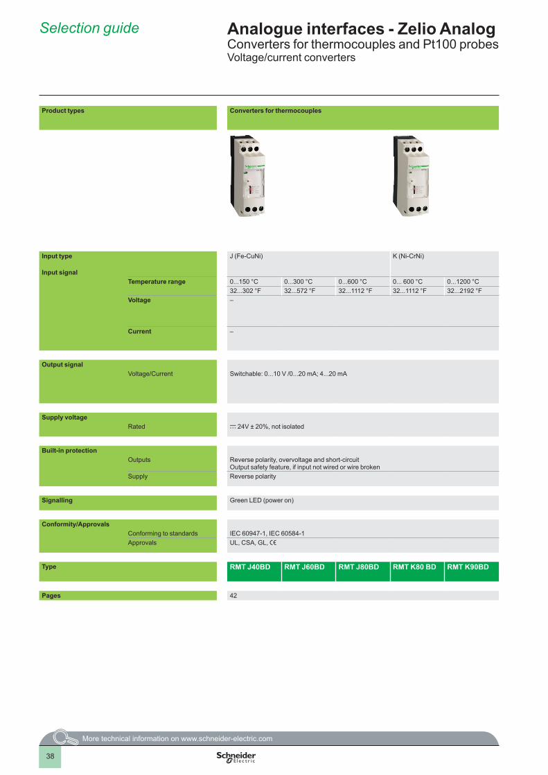
Product types Converters for thermocouples Converters for Universal and Optimum Pt100 probes Voltage/current converters
Input type J (Fe-CuNi) K (Ni-CrNi) Pt100, 2, 3 and 4-wire –
Input signalTemperature range 0...150 °C 0...300 °C 0...600 °C 0... 600 °C 0...1200 °C - 40...40 °C -100...100 °C 0...100 °C 0...250 °C 0...500 °C –
32...302 °F 32...572 °F 32...1112 °F 32...1112 °F 32...2192 °F - 40...104 °F - 148...212 °F 32...212 °F 32...482 °F 32...932 °FVoltage –
– 0...10 V 0...10 V; ± 10 V 0...50 V; 0...300 V; 0...500 V c ora 50/60 Hz
–
Current – – 4...20 mA 0...20 mA; 4...20 mA
– 0...1.5 A; 0...5 A; 0...15 A c or a 50/60 Hz
Output signalVoltage/Current Switchable: 0...10 V /0...20 mA; 4...20 mA Switchable: 0...10 V or
4...20 mASwitchable: 0...10 V; ±10 V/ 0...20 mA; 4...20 mA
Switchable: 0...10 V/ 4...20 mA; 0...20 mA
0...10 V or 0...20 mA or 4...20 mA
0... 10 V/0...20 mA , 4...20 mA for the Universal range RMP Tp0BD0...10 V or 4...20 mA for the Optimum range RMP Tp3BD
Supply voltageRated c 24V ± 20%, not isolated c 24V ± 20%, not isolated c 24V ± 20%, isolated
Built-in protectionOutputs Reverse polarity, overvoltage and short-circuit
Output safety feature, if input not wired or wire brokenReverse polarity, overvoltage and short-circuit Output safety feature, if input not wired or wire broken
Supply Reverse polarity Reverse polarity
Signalling Green LED (power on) Green LED (power on)
Conformity/ApprovalsConforming to standards IEC 60947-1, IEC 60584-1 IEC 60751, DIN 43 760 IEC 60947-1Approvals UL, CSA, GL, e UL, CSA, GL, e
Type RMT J40BD RMT J60BD RMT J80BD RMT K80 BD RMT K90BD RMP T1pBD RMP T2pBD RMP T3pBD RMP T5pBD RMP T7pBD RMC N22BD RMC L55BD RMC V60BD RMC A61BD
Pages 42 42 and 43
Selection guide Analogue interfaces - Zelio AnalogConverters for thermocouples and Pt100 probesVoltage/current converters
1
2
3
4
5
6
7
8
9
10
39
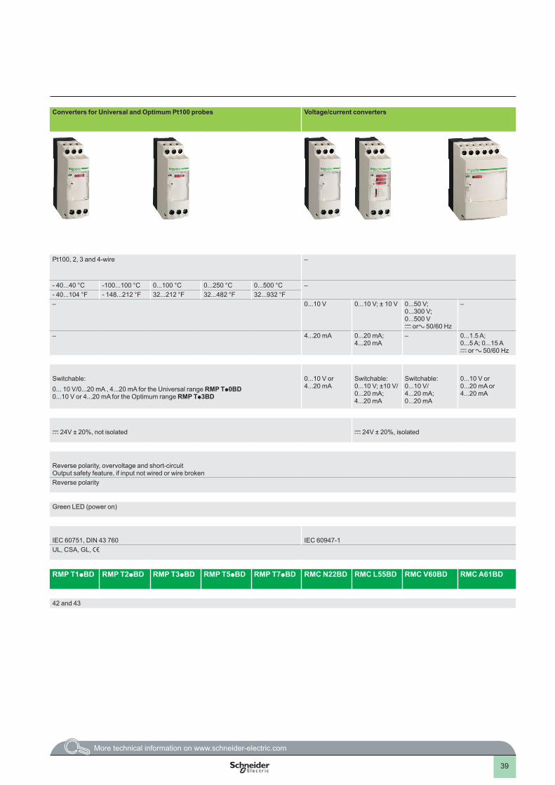
Product types Converters for thermocouples Converters for Universal and Optimum Pt100 probes Voltage/current converters
Input type J (Fe-CuNi) K (Ni-CrNi) Pt100, 2, 3 and 4-wire –
Input signalTemperature range 0...150 °C 0...300 °C 0...600 °C 0... 600 °C 0...1200 °C - 40...40 °C -100...100 °C 0...100 °C 0...250 °C 0...500 °C –
32...302 °F 32...572 °F 32...1112 °F 32...1112 °F 32...2192 °F - 40...104 °F - 148...212 °F 32...212 °F 32...482 °F 32...932 °FVoltage –
– 0...10 V 0...10 V; ± 10 V 0...50 V; 0...300 V; 0...500 V c ora 50/60 Hz
–
Current – – 4...20 mA 0...20 mA; 4...20 mA
– 0...1.5 A; 0...5 A; 0...15 A c or a 50/60 Hz
Output signalVoltage/Current Switchable: 0...10 V /0...20 mA; 4...20 mA Switchable: 0...10 V or
4...20 mASwitchable: 0...10 V; ±10 V/ 0...20 mA; 4...20 mA
Switchable: 0...10 V/ 4...20 mA; 0...20 mA
0...10 V or 0...20 mA or 4...20 mA
0... 10 V/0...20 mA , 4...20 mA for the Universal range RMP Tp0BD0...10 V or 4...20 mA for the Optimum range RMP Tp3BD
Supply voltageRated c 24V ± 20%, not isolated c 24V ± 20%, not isolated c 24V ± 20%, isolated
Built-in protectionOutputs Reverse polarity, overvoltage and short-circuit
Output safety feature, if input not wired or wire brokenReverse polarity, overvoltage and short-circuit Output safety feature, if input not wired or wire broken
Supply Reverse polarity Reverse polarity
Signalling Green LED (power on) Green LED (power on)
Conformity/ApprovalsConforming to standards IEC 60947-1, IEC 60584-1 IEC 60751, DIN 43 760 IEC 60947-1Approvals UL, CSA, GL, e UL, CSA, GL, e
Type RMT J40BD RMT J60BD RMT J80BD RMT K80 BD RMT K90BD RMP T1pBD RMP T2pBD RMP T3pBD RMP T5pBD RMP T7pBD RMC N22BD RMC L55BD RMC V60BD RMC A61BD
Pages 42 42 and 43
1
2
3
4
5
6
7
8
9
10
40
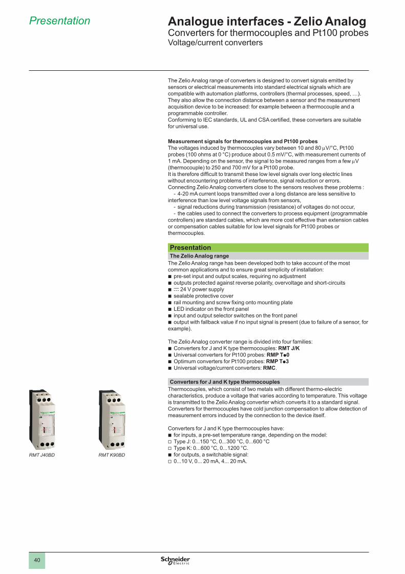
Presentation
The Zelio Analog range of converters is designed to convert signals emitted by sensors or electrical measurements into standard electrical signals which are compatible with automation platforms, controllers (thermal processes, speed, …).They also allow the connection distance between a sensor and the measurement acquisition device to be increased: for example between a thermocouple and a programmable controller.Conforming to IEC standards, UL and CSA certified, these converters are suitable for universal use.
Measurement signals for thermocouples and Pt100 probesThe voltages induced by thermocouples vary between 10 and 80 mV/°C, Pt100 probes (100 ohms at 0 °C) produce about 0.5 mV/°C, with measurement currents of 1 mA. Depending on the sensor, the signal to be measured ranges from a few mV (thermocouple) to 250 and 700 mV for a Pt100 probe. It is therefore difficult to transmit these low level signals over long electric lines without encountering problems of interference, signal reduction or errors. Connecting Zelio Analog converters close to the sensors resolves these problems :
- 4-20 mA current loops transmitted over a long distance are less sensitive to interference than low level voltage signals from sensors,
- signal reductions during transmission (resistance) of voltages do not occur,- the cables used to connect the converters to process equipment (programmable
controllers) are standard cables, which are more cost effective than extension cables or compensation cables suitable for low level signals for Pt100 probes or thermocouples.
PresentationThe Zelio Analog range
The Zelio Analog range has been developed both to take account of the most common applications and to ensure great simplicity of installation:b pre-set input and output scales, requiring no adjustmentb outputs protected against reverse polarity, overvoltage and short-circuitsb c 24 V power supplyb sealable protective coverb rail mounting and screw fixing onto mounting plateb LED indicator on the front panelb input and output selector switches on the front panelb output with fallback value if no input signal is present (due to failure of a sensor, for example).
The Zelio Analog converter range is divided into four families:b Converters for J and K type thermocouples: RMT J/K b Universal converters for Pt100 probes: RMP Tp0 b Optimum converters for Pt100 probes: RMP Tp3 b Universal voltage/current converters: RMC.
Converters for J and K type thermocouples Thermocouples, which consist of two metals with different thermo-electric characteristics, produce a voltage that varies according to temperature. This voltage is transmitted to the Zelio Analog converter which converts it to a standard signal.Converters for thermocouples have cold junction compensation to allow detection of measurement errors induced by the connection to the device itself.
Converters for J and K type thermocouples have:b for inputs, a pre-set temperature range, depending on the model:v Type J: 0...150 °C, 0...300 °C, 0...600 °Cv Type K: 0...600 °C, 0...1200 °C.b for outputs, a switchable signal:v 0...10 V, 0... 20 mA, 4... 20 mA.
RMT J40BD RMT K90BD
Analogue interfaces - Zelio AnalogConverters for thermocouples and Pt100 probesVoltage/current converters
1
2
3
4
5
6
7
8
9
10
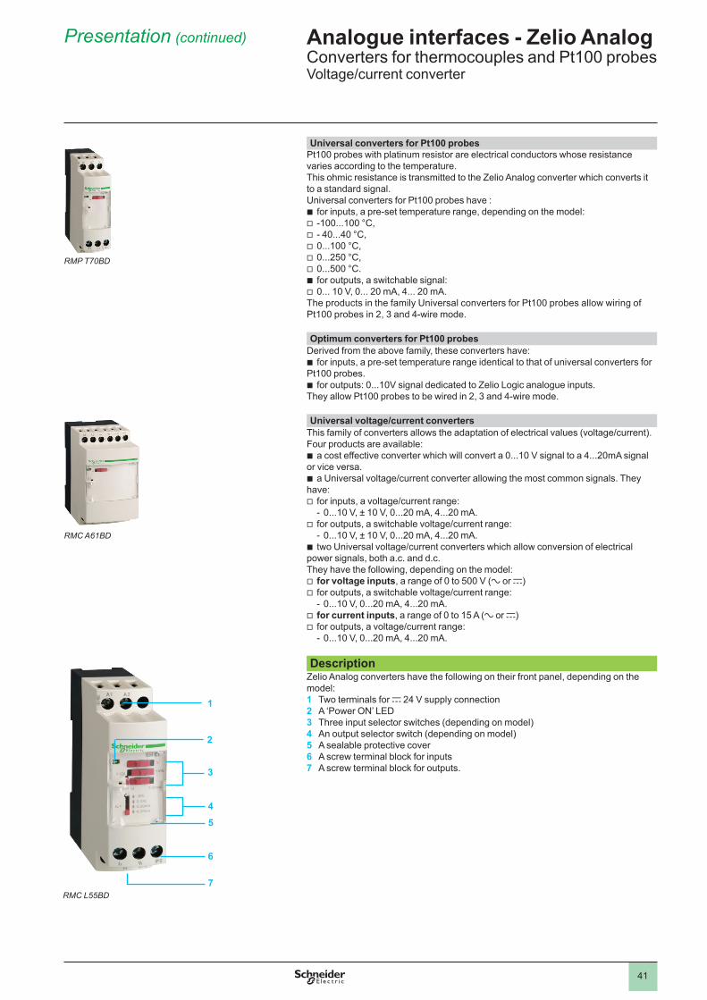
41
Universal converters for Pt100 probes Pt100 probes with platinum resistor are electrical conductors whose resistance varies according to the temperature. This ohmic resistance is transmitted to the Zelio Analog converter which converts it to a standard signal.Universal converters for Pt100 probes have :b for inputs, a pre-set temperature range, depending on the model: v -100...100 °C, v - 40...40 °C, v 0...100 °C, v 0...250 °C, v 0...500 °C.b for outputs, a switchable signal: v 0... 10 V, 0... 20 mA, 4... 20 mA.The products in the family Universal converters for Pt100 probes allow wiring of Pt100 probes in 2, 3 and 4-wire mode. Optimum converters for Pt100 probes
Derived from the above family, these converters have:b for inputs, a pre-set temperature range identical to that of universal converters for Pt100 probes. b for outputs: 0...10V signal dedicated to Zelio Logic analogue inputs. They allow Pt100 probes to be wired in 2, 3 and 4-wire mode. Universal voltage/current converters
This family of converters allows the adaptation of electrical values (voltage/current). Four products are available: b a cost effective converter which will convert a 0...10 V signal to a 4...20mA signal or vice versa.b a Universal voltage/current converter allowing the most common signals. They have:v for inputs, a voltage/current range:
- 0...10 V, ± 10 V, 0...20 mA, 4...20 mA.v for outputs, a switchable voltage/current range:
- 0...10 V, ± 10 V, 0...20 mA, 4...20 mA.b two Universal voltage/current converters which allow conversion of electrical power signals, both a.c. and d.c.They have the following, depending on the model:v for voltage inputs, a range of 0 to 500 V (a or c)v for outputs, a switchable voltage/current range:
- 0...10 V, 0...20 mA, 4...20 mA.v for current inputs, a range of 0 to 15 A (a or c)v for outputs, a voltage/current range:
- 0...10 V, 0...20 mA, 4...20 mA.
DescriptionZelio Analog converters have the following on their front panel, depending on the model:1 Two terminals for c 24 V supply connection2 A ‘Power ON’ LED3 Three input selector switches (depending on model)4 An output selector switch (depending on model)5 A sealable protective cover6 A screw terminal block for inputs7 A screw terminal block for outputs.
Presentation (continued)
RMP T70BD
RMC A61BD
3
5
2
6
4
RMC L55BD7
1
Analogue interfaces - Zelio AnalogConverters for thermocouples and Pt100 probesVoltage/current converter
1
2
3
4
5
6
7
8
9
10
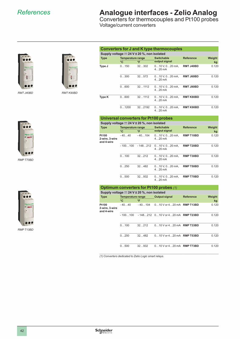
42
Converters for J and K type thermocouplesSupply voltage c 24 V ± 20 %, non isolatedType Temperature range Switchable
output signalReference Weight
°C °F kgType J 0…150 32…302 0…10 V, 0…20 mA,
4…20 mARMT J40BD 0.120
0…300 32…572 0…10 V, 0…20 mA, 4…20 mA
RMT J60BD 0.120
0…600 32…1112 0…10 V, 0…20 mA, 4…20 mA
RMT J80BD 0.120
Type K 0…600 32…1112 0…10 V, 0…20 mA, 4…20 mA
RMT K80BD 0.120
0…1200 32…2192 0…10 V, 0…20 mA, 4…20 mA
RMT K90BD 0.120
Universal converters for Pt100 probesSupply voltage c 24 V ± 20 %, non isolatedType Temperature range Switchable
output signalReference Weight
°C °F kgPt100 2-wire, 3-wire and 4-wire
- 40…40 - 40…104 0…10 V, 0…20 mA, 4…20 mA
RMP T10BD 0.120
- 100…100 - 148…212 0…10 V, 0…20 mA, 4…20 mA
RMP T20BD 0.120
0…100 32…212 0…10 V, 0…20 mA, 4…20 mA
RMP T30BD 0.120
0…250 32…482 0…10 V, 0…20 mA, 4…20 mA
RMP T50BD 0.120
0…500 32…932 0…10 V, 0…20 mA, 4…20 mA
RMP T70BD 0.120
Optimum converters for Pt100 probes (1)Supply voltage c 24 V ± 20 %, non isolatedType Temperature range Output signal Reference Weight
°C °F kgPt100 2-wire, 3-wire and 4-wire
- 40…40 - 40…104 0…10 V or 4…20 mA RMP T13BD 0.120
- 100…100 - 148…212 0…10 V or 4…20 mA RMP T23BD 0.120
0…100 32…212 0…10 V or 4…20 mA RMP T33BD 0.120
0…250 32…482 0…10 V or 4…20 mA RMP T53BD 0.120
0…500 32…932 0…10 V or 4…20 mA RMP T73BD 0.120
(1) Converters dedicated to Zelio Logic smart relays.
References Analogue interfaces - Zelio AnalogConverters for thermocouples and Pt100 probesVoltage/current converters
RMT J40BD RMT K90BD
RMP T13BD
RMP T70BD
1
2
3
4
5
6
7
8
9
10
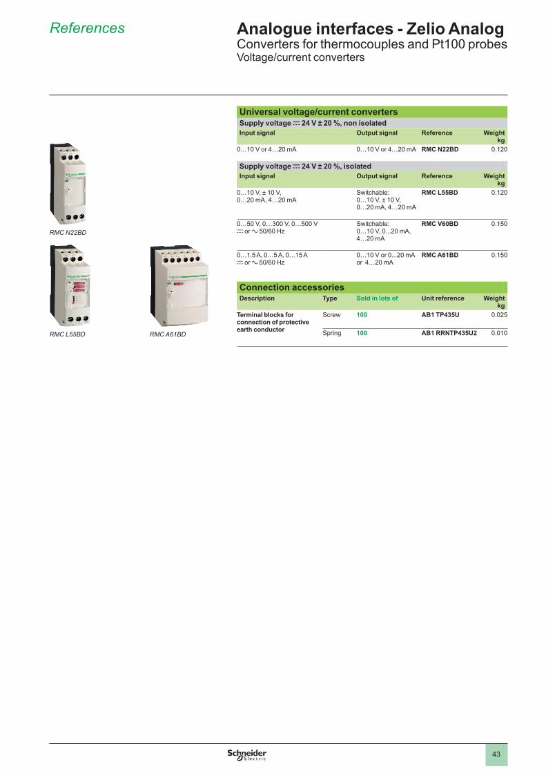
43
References Analogue interfaces - Zelio AnalogConverters for thermocouples and Pt100 probesVoltage/current converters
Universal voltage/current convertersSupply voltage c 24 V ± 20 %, non isolatedInput signal Output signal Reference Weight
kg0…10 V or 4…20 mA 0…10 V or 4…20 mA RMC N22BD 0.120
Supply voltage c 24 V ± 20 %, isolated Input signal Output signal Reference Weight
kg0…10 V, ± 10 V, 0…20 mA, 4…20 mA
Switchable:0…10 V, ± 10 V, 0…20 mA, 4…20 mA
RMC L55BD 0.120
0…50 V, 0…300 V, 0…500 Vc or a 50/60 Hz
Switchable:0…10 V, 0...20 mA, 4…20 mA
RMC V60BD 0.150
0…1.5 A, 0…5 A, 0…15 Ac or a 50/60 Hz
0…10 V or 0...20 mA or 4…20 mA
RMC A61BD 0.150
Connection accessoriesDescription Type Sold in lots of Unit reference Weight
kgTerminal blocks for connection of protective earth conductor
Screw 100 AB1 TP435U 0.025
Spring 100 AB1 RRNTP435U2 0.010
RMC N22BD
RMC L55BD RMC A61BD
1
2
3
4
5
6
7
8
9
10
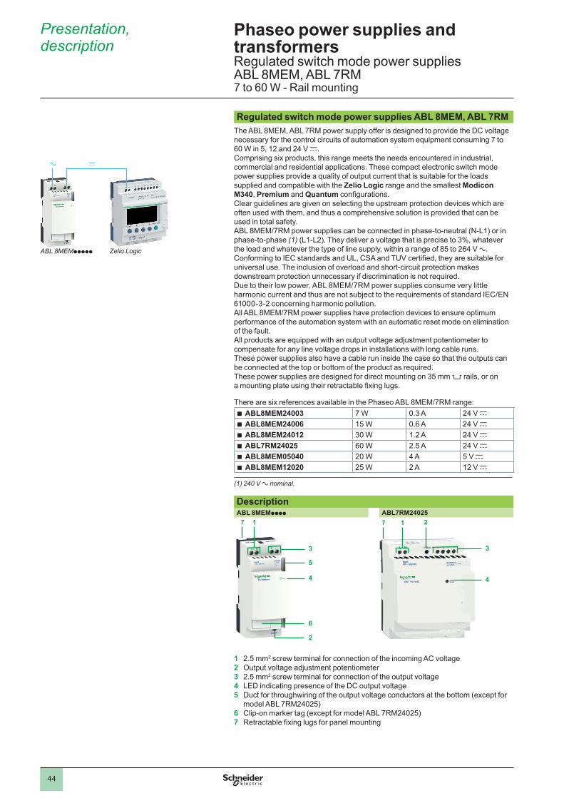
44
Presentation, description
Regulated switch mode power supplies ABL 8MEM, ABL 7RM The ABL 8MEM, ABL 7RM power supply offer is designed to provide the DC voltage necessary for the control circuits of automation system equipment consuming 7 to 60 W in 5, 12 and 24 V c. Comprising six products, this range meets the needs encountered in industrial, commercial and residential applications. These compact electronic switch mode power supplies provide a quality of output current that is suitable for the loads supplied and compatible with the Zelio Logic range and the smallest Modicon M340, Premium and Quantum configurations.Clear guidelines are given on selecting the upstream protection devices which are often used with them, and thus a comprehensive solution is provided that can be used in total safety.ABL 8MEM/7RM power supplies can be connected in phase-to-neutral (N-L1) or in phase-to-phase (1) (L1-L2). They deliver a voltage that is precise to 3%, whatever the load and whatever the type of line supply, within a range of 85 to 264 V a. Conforming to IEC standards and UL, CSA and TUV certified, they are suitable for universal use. The inclusion of overload and short-circuit protection makes downstream protection unnecessary if discrimination is not required.Due to their low power, ABL 8MEM/7RM power supplies consume very little harmonic current and thus are not subject to the requirements of standard IEC/EN 61000-3-2 concerning harmonic pollution.All ABL 8MEM/7RM power supplies have protection devices to ensure optimum performance of the automation system with an automatic reset mode on elimination of the fault.All products are equipped with an output voltage adjustment potentiometer to compensate for any line voltage drops in installations with long cable runs.These power supplies also have a cable run inside the case so that the outputs can be connected at the top or bottom of the product as required.These power supplies are designed for direct mounting on 35 mm 5 rails, or on a mounting plate using their retractable fixing lugs.
There are six references available in the Phaseo ABL 8MEM/7RM range: b ABL8MEM24003 7 W 0.3 A 24 V c b ABL8MEM24006 15 W 0.6 A 24 V c b ABL8MEM24012 30 W 1.2 A 24 V c b ABL7RM24025 60 W 2.5 A 24 V c b ABL8MEM05040 20 W 4 A 5 V c b ABL8MEM12020 25 W 2 A 12 V c
(1) 240 V a nominal.
DescriptionABL 8MEMpppp ABL7RM24025
3
1
4
5
2
6
7
3
1
4
27
1 2.5 mm2 screw terminal for connection of the incoming AC voltage2 Output voltage adjustment potentiometer3 2.5 mm2 screw terminal for connection of the output voltage4 LED indicating presence of the DC output voltage5 Duct for throughwiring of the output voltage conductors at the bottom (except for
model ABL 7RM24025)6 Clip-on marker tag (except for model ABL 7RM24025)7 Retractable fixing lugs for panel mounting
Phaseo power supplies and transformersRegulated switch mode power suppliesABL 8MEM, ABL 7RM 7 to 60 W - Rail mounting
ca
ABL 8MEMppppp Zelio Logic
1
2
3
4
5
6
7
8
9
10
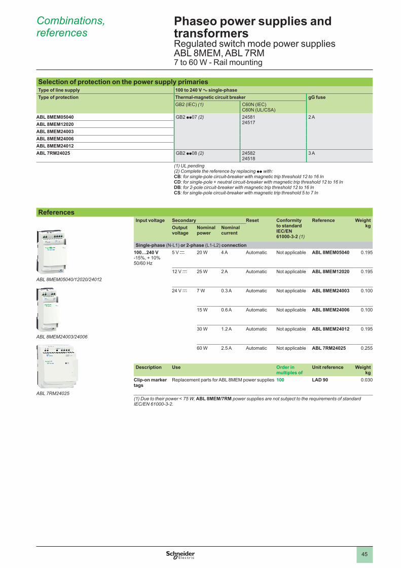
45
Phaseo power supplies and transformersRegulated switch mode power supplies ABL 8MEM, ABL 7RM 7 to 60 W - Rail mounting
Combinations, references
Selection of protection on the power supply primariesType of line supply 100 to 240 V a single-phaseType of protection Thermal-magnetic circuit breaker gG fuse
GB2 (IEC) (1) C60N (IEC) C60N (UL/CSA)
ABL 8MEM05040 GB2 pp07 (2) 24581 24517
2 AABL 8MEM12020ABL 8MEM24003ABL 8MEM24006ABL 8MEM24012ABL 7RM24025 GB2 pp08 (2) 24582
245183 A
(1) UL pending(2) Complete the reference by replacing pp with:CB: for single-pole circuit-breaker with magnetic trip threshold 12 to 16 InCD: for single-pole + neutral circuit-breaker with magnetic trip threshold 12 to 16 InDB: for 2-pole circuit-breaker with magnetic trip threshold 12 to 16 InCS: for single-pole circuit-breaker with magnetic trip threshold 5 to 7 In
ReferencesInput voltage Secondary Reset Conformity
to standard IEC/EN 61000-3-2 (1)
Reference Weight kgOutput
voltageNominal power
Nominal current
Single-phase (N-L1) or 2-phase (L1-L2) connection100…240 V -15%, + 10%50/60 Hz
5 V c 20 W 4 A Automatic Not applicable ABL 8MEM05040 0.195
12 V c 25 W 2 A Automatic Not applicable ABL 8MEM12020 0.195
24 V c 7 W 0.3 A Automatic Not applicable ABL 8MEM24003 0.100
15 W 0.6 A Automatic Not applicable ABL 8MEM24006 0.100
30 W 1.2 A Automatic Not applicable ABL 8MEM24012 0.195
60 W 2.5 A Automatic Not applicable ABL 7RM24025 0.255
Description Use Order in multiples of
Unit reference Weightkg
Clip-on marker tags
Replacement parts for ABL 8MEM power supplies 100 LAD 90 0.030
(1) Due to their power < 75 W, ABL 8MEM/7RM power supplies are not subject to the requirements of standard IEC/EN 61000-3-2.
ABL 8MEM05040/12020/24012
ABL 8MEM24003/24006
ABL 7RM24025
1
2
3
4
5
6
7
8
9
10

The information provided in this documentation contains general descriptions and/or technical characteristics of the performance of the products contained herein. This documentation is not intended as a substitute for and is not to be used for determining suitability or reliability of these products for specifi c user applications. It is the duty of any such user or integrator to perform the appropriate and complete risk analysis, evaluation and testing of the products with respect to the relevant specifi c application or use thereof. Neither Schneider Electric nor any of its affi liates or subsidiaries shall be responsible or liable for misuse of the information contained herein.
Design: Schneider ElectricPhotos: Schneider ElectricPrinted by:
Head Offi ce35, rue Joseph MonierF-92500 Rueil-MalmaisonFrance
www.schneider-electric.comSchneider Electric Industries SAS
October 2011ART. 960627
DIA
3ED
2111
202E
N