ZAE OPERATING INSTRUCTIONS
56
ZAE OPERATING INSTRUCTIONS GEARBOXES AND GEARED MOTORS EDITION 07/2020
Transcript of ZAE OPERATING INSTRUCTIONS

ZAE OPERATING INSTRUCTIONSG E A R B O X E S A N D G E A R E D M O T O R S
E D I T I O N 0 7 / 2 0 2 0


1
Ex_B
A_20
20IV
Z.fm
Table of contents
1. Introduction . . . . . . . . . . . . . . . . . . . . . . . . . . . . . . . . . . . . . . . . . . . . . . . . . . . . . . . . . . . . . . . . . . . . . . . . . . . . . 2
2. Scope and application of the gear units and geared motors . . . . . . . . . . . . . . . . . . . . . . . . . . . . . . . . . . . . . 2
3. Basic descriptions of the gear units and geared motors with drawings of replacement parts and parts list . . . . . . . . . . . . . . . . . . . . . . . . . . . . . . . . . . . . . . . . . . . . . . . . . . . . . . . . . . . . . . . . . . . . . . . . . . . . . . . . 23.1 Worm gear Units and worm gear motors . . . . . . . . . . . . . . . . . . . . . . . . . . . . . . . . . . . . . . . . . . . . . . . . . 23.2 Bevel helical gear units and bevel helical geared motors. . . . . . . . . . . . . . . . . . . . . . . . . . . . . . . . . . . . . 83.3 Worm helical gear units and worm helical geared motors . . . . . . . . . . . . . . . . . . . . . . . . . . . . . . . . . . . 103.4 Helical worm gears and helical worm gear motors . . . . . . . . . . . . . . . . . . . . . . . . . . . . . . . . . . . . . . . . . 143.5 Bevel gear units and bevel geared motors . . . . . . . . . . . . . . . . . . . . . . . . . . . . . . . . . . . . . . . . . . . . . . . 16
4. Condition on delivery and warranty . . . . . . . . . . . . . . . . . . . . . . . . . . . . . . . . . . . . . . . . . . . . . . . . . . . . . . . . 17
5. Transportation and storage . . . . . . . . . . . . . . . . . . . . . . . . . . . . . . . . . . . . . . . . . . . . . . . . . . . . . . . . . . . . . . . 18
6. Installation and commissioning . . . . . . . . . . . . . . . . . . . . . . . . . . . . . . . . . . . . . . . . . . . . . . . . . . . . . . . . . . . 186.1 Gear units and geared motors with projecting shaft ends . . . . . . . . . . . . . . . . . . . . . . . . . . . . . . . . . . . 186.2 Hollow shaft gear units and geared motors . . . . . . . . . . . . . . . . . . . . . . . . . . . . . . . . . . . . . . . . . . . . . . 186.3 Installing couplings or other components . . . . . . . . . . . . . . . . . . . . . . . . . . . . . . . . . . . . . . . . . . . . . . . . 196.4 Commissioning worm gear units and variants . . . . . . . . . . . . . . . . . . . . . . . . . . . . . . . . . . . . . . . . . . . . 196.5 Commissioning bevel gear units and variants . . . . . . . . . . . . . . . . . . . . . . . . . . . . . . . . . . . . . . . . . . . . 196.6 Electrical connections . . . . . . . . . . . . . . . . . . . . . . . . . . . . . . . . . . . . . . . . . . . . . . . . . . . . . . . . . . . . . . . 206.7 Mounting and commissioning in hazardous areas . . . . . . . . . . . . . . . . . . . . . . . . . . . . . . . . . . . . . . . . . 20
7. Operation . . . . . . . . . . . . . . . . . . . . . . . . . . . . . . . . . . . . . . . . . . . . . . . . . . . . . . . . . . . . . . . . . . . . . . . . . . . . . . 247.1 Lubrication of worm gear units and variants . . . . . . . . . . . . . . . . . . . . . . . . . . . . . . . . . . . . . . . . . . . . . . 24
7.1.1 Lubricant amounts . . . . . . . . . . . . . . . . . . . . . . . . . . . . . . . . . . . . . . . . . . . . . . . . . . . . . . . . . . . 257.1.2 Mounting positions for vent filters and oil fittings . . . . . . . . . . . . . . . . . . . . . . . . . . . . . . . . . . . . 27
7.2 Lubrication of bevel gear units and variants . . . . . . . . . . . . . . . . . . . . . . . . . . . . . . . . . . . . . . . . . . . . . . 327.2.1 Lubricant amounts . . . . . . . . . . . . . . . . . . . . . . . . . . . . . . . . . . . . . . . . . . . . . . . . . . . . . . . . . . . 337.2.2 Mounting positions for vent filters and oil fittings . . . . . . . . . . . . . . . . . . . . . . . . . . . . . . . . . . . . 34
7.3 Lubricants and manufacturers . . . . . . . . . . . . . . . . . . . . . . . . . . . . . . . . . . . . . . . . . . . . . . . . . . . . . . . . 367.4 Troubleshooting . . . . . . . . . . . . . . . . . . . . . . . . . . . . . . . . . . . . . . . . . . . . . . . . . . . . . . . . . . . . . . . . . . . 377.5 Operation in hazardous areas . . . . . . . . . . . . . . . . . . . . . . . . . . . . . . . . . . . . . . . . . . . . . . . . . . . . . . . . 38
8. Inspection and maintenance . . . . . . . . . . . . . . . . . . . . . . . . . . . . . . . . . . . . . . . . . . . . . . . . . . . . . . . . . . . . . . 418.1 General information . . . . . . . . . . . . . . . . . . . . . . . . . . . . . . . . . . . . . . . . . . . . . . . . . . . . . . . . . . . . . . . . 418.2 Inspection and maintenance in hazardous areas . . . . . . . . . . . . . . . . . . . . . . . . . . . . . . . . . . . . . . . . . . 42
9. Electric motors . . . . . . . . . . . . . . . . . . . . . . . . . . . . . . . . . . . . . . . . . . . . . . . . . . . . . . . . . . . . . . . . . . . . . . . . . 459.1 Brake motors . . . . . . . . . . . . . . . . . . . . . . . . . . . . . . . . . . . . . . . . . . . . . . . . . . . . . . . . . . . . . . . . . . . . . 459.2 Three-phase motors . . . . . . . . . . . . . . . . . . . . . . . . . . . . . . . . . . . . . . . . . . . . . . . . . . . . . . . . . . . . . . . . 479.3 Use in hazardous areas . . . . . . . . . . . . . . . . . . . . . . . . . . . . . . . . . . . . . . . . . . . . . . . . . . . . . . . . . . . . . 47
10. Recycling . . . . . . . . . . . . . . . . . . . . . . . . . . . . . . . . . . . . . . . . . . . . . . . . . . . . . . . . . . . . . . . . . . . . . . . . . . . . . . 48
11. Declaration of conformity . . . . . . . . . . . . . . . . . . . . . . . . . . . . . . . . . . . . . . . . . . . . . . . . . . . . . . . . . . . . . . . . 49

2
1. IntroductionThis operator's manual contains information on assembly, commissioning, and operationas well as inspection and maintenance of ZAE gear units and geared motors.The information in this manual applies to gear units and geared motors in normal opera-tion as well as to applications in potentially explosive atmospheres. Gear units andgeared motors of categories 3G and 3D, group II, and categories 2G and 2D, group II, inconformity with Directive 2014/34/EU are considered in this manual.
2. Scope and application of the gear units and geared motorsZAE standard gear units include worm gear units, worm helical gear units, helical wormgear units, and bevel gear units as both gear unit and geared motor variants. Thesestandard products meet the maximum requirements for categories 2G and 2D, group II,in conformity with Directive 2014/34/EU:
Worm gear unit types E, M, and S Sizes 040 to 400Double worm gear unit types D and DM Sizes 050 to 400Bevel helical gear unit types E, M, and S Sizes 222 to 523Worm helical gear unit types E and M Sizes 012 to 513Helical worm gear unit types GE and GM Sizes 050 to 200Bevel gear unit types W, MW, and SW Sizes 088 to 260Worm gear set types SO and MO Sizes 040 to 630Worm gear set types SR and MR Sizes 100 to 630Worm gear set types SH and MH Sizes 100 to 630
AIf these devices are used in potentially explosive gas and dust atmospheresinstead of under normal operating conditions, be sure to observe the additionalsafety instructions and regulations marked with the symbol!
3. Basic descriptions of the gear units and geared motors with drawings of replacement parts and parts list
3.1 Worm gear Units and worm gear motorsThese are single-stage worm gear units/worm gear motors with differing designs basedon their respective center distances.

3
Types E, M, and S 040–080
80.1
26.2
32
31.2.230
30.1
26.1
10
31.1
1
30.2
29.2
29.3
8.5
8.329.1
30
75+6
4
33
35
34
34
33
8.2
38
2.2
37
74
38.2
8.1
3
5+6
2.1
3
3
2.4
2.3
17
16
15.1
31.2.3
14
23
10
11.113
24
25
26.1
27
26.2
28
18
19
15.2
20
13
14
14
11.2
11.313
12
11.413
9
36
8.4
22
80
99
31.2.1
1 Gear unit housing 20 Adjusting ring2.1 Double-sided worm 22 O-ring2.2 Double-sided motor worm 23 Housing cover2.3 Single-sided worm 24 Set of shim rings2.4 Single-sided motor worm 25 Snap ring3 Key 26.1 Shaft cap4 Angular contact ball bearing 26.2 Radial shaft seal5 Set of shim rings 27 F flange housing6 Support washer 28 Cheese head screw7 Retaining ring 29.1 Yoke and motor flange8.1 Shaft cap 29.2 Servo yoke8.2 Radial shaft seal 29.3 Yoke and motor flange8.3 Radial shaft seal 30 Cheese head screw8.4 Radial shaft seal 30.1 Lock washer8.5 Seal ring holder 30.2 Cheese head screw9 Set of shim rings 31.1 Coupling10 Grooved ball bearing 31.2 KTR Rotex GS11.1 Single-sided wheel shaft 31.2.1 Coupling hub11.2 Double-sided wheel shaft 31.2.2 Ring gear11.3 Hollow shaft 31.2.3 Coupling hub11.4 Hollow shaft for locking ring version 32 HSD locking ring12 Sliding bushing for locking ring version 33 Torque support + bushing13 Key 34 Cheese head screw14 Key 35 Gear mounting base15.1 Worm gear for friction clutch 36 Warning sign15.2 Worm gear 37 Threaded plug + seal ring16 Coupling hub 38 Threaded plug + seal ring17 Key 80 Threaded plug/vent plug18 Cone ring 80.1 Seal ring19 Conical spring washer 99 Motor

4
Types E, M, and S 100–200
8.1
29.3
30.3
31.2
.2
29.4
30.4
99
31.1
8.2
30.2
29.5
30.1
29.1
8.1
35 34
33
34
33
27.1
28.2
26
26.1
28.2
27.2
80+8
1
84+8
5
82+8
3
84+8
5
80+8
1
82+8
3
4
80+8
1
84+8
5
84+8
5
80+8
1
38
32.
1
3 3
2.2 2.
3
3
2.4
47
4645
44
43
30.1
8.1
29.1
4
910
13.1
1411
.3
1413
.1
1411
.415
.2
15.4
12
15.3
27.2
28.1
26.1
28.2
10
26
13.2
9
11.5
17 16
15.1
18
1920
32
5
4027
.1
31.2
.3
31.2
.180
+81
29.2
82+8
3
41
37
36
1
82+8
3
41
26
26.1

5
Types E, M, and S 100–200
1 Gear unit housing 29.2 Yoke and motor flange2.1 Double-sided worm 29.3 Servomotor yoke2.2 Double-sided motor worm 29.4 Intermediate flange2.3 Single-sided worm 29.5 Motor yoke2.4 Single-sided motor worm 30.1 Cheese head screw3 Key 30.2 Cheese head screw4 Angular contact ball bearing 30.3 Cheese head screw5 Set of shim rings 30.4 Cheese head screw8.1 Radial shaft seal 31.1 Coupling8.2 Radial shaft seal 31.2 KTR Rotex GS9 Set of shim rings 31.2.1 Coupling hub10 Grooved ball bearing 31.2.2 Ring gear11.3 Single-sided wheel shaft 31.2.3 Coupling hub11.4 Double-sided wheel shaft 32 HSD locking ring11.5 Hollow shaft friction clutch 33 Torque support + MEGI bushing12 Sliding bushing for locking ring version 34 Cheese head screw13.1 Key 35 Gear mounting base13.2 Key 36 Warning sign14 Key 37 Threaded plug + seal ring15.1 Worm gear for friction clutch 38 Threaded plug + seal ring15.2 Worm gear 40 Spacer ring15.3 Worm gear with hollow hub 41 Nilos ring15.4 Worm gear with hollow hub + HSD 43 Tolerance ring16 Coupling hub 44 Fan17 Key 45 Fan shroud18 Cone ring 46 Cheese head screw19 Conical spring washer 47 Cheese head screw20 Adjusting ring 80 Threaded plug/vent plug26 Radial shaft seal 81 Seal ring26.1 Shaft cap 82 Cheese head screw27.1 Housing C flange 83 Seal ring27.2 Housing F flange 84 Threaded plug28.1 Cheese head screw 85 Seal ring28.2 Cheese head screw 99 Motor29.1 Annular cap

6
Types E and M 250, 315, 400

7
Types E and M 250, 315, 400
1 Gear unit housing 30.1 Cheese head screw2.1 Double-sided worm shaft 30.2 Cheese head screw2.2 Double-sided motor worm shaft 31 Coupling assembly2.3 Single-sided worm shaft 32 Locking ring2.4 Single-sided motor worm shaft 33.1 Gear mounting bases3 Key 33.2 Torque support4 Grooved ball bearing 33.2.1 MEGI bushing5 Set of shim rings 34 Cheese head screw8.2 Radial shaft seal 35 Vent filter8.3 Radial shaft seal 40 Spacer ring9.1 Set of shim rings 41.1 Nilos ring9.2 Set of shim rings 41.2 Nilos ring10.1 Grooved ball bearing 43 Tolerance ring10.2 Grooved ball bearing 44 Fan11.1 Single-sided wheel shaft 45 Fan shroud11.2 Double-sided wheel shaft 46 Cheese head screw12 Sliding bushing for locking ring 47 Cheese head screw13 Key 48 Cheese head screw14 Key 49 Threaded plug15.2 Worm gear 50 Warning sign15.3 Worm gear with hollow shaft 51 Nilos ring15.4 Worm gear with hollow shaft for locking ring 52 Tapered roller bearing26.1 Shaft cap 53 Spacer ring26.2 Radial shaft seal for solid output shaft 54 Groove nut with retaining washer26.3 Radial shaft seal for hollow output shaft 55 Grease fitting27.1 Housing flange for wheel shaft 56.1 Annular cap for wheel shaft27.2 Housing flange for hollow shaft 56.2 Annular cap for hollow shaft28.1 Cheese head screw 57.1-3 Cheese head screws28.2 Cheese head screw 58 Eyebolt29.1 Annular cap 99 Motor29.2 Motor yoke
8
3.2 Bevel helical gear units and bevel helical geared motors
Types E, M, and S 222–523
37+3
8
32
2326
.126
.2
2081
+82
4419
47
48+4
9
4651
+52
5012
2253
42+4
341
18.1
42+4
341
17
21
36
29
20.1
+30
20
8281
216
4.1
6+7
59
11.3
14
14
11.3
15 11.2
14
14
40
11.1
13
1024
+25 23
26
32.1
29.2
+30
39
15
29.1
+30
3945
16
26.1
13
13
31.3
11.4
1314
18.2
13
11.5
58
59
46.1
4.2
4.2
55.1
18.1
42+4
341
8
57
8281
5319
18.2
55
31.1
31.2
13
40
20.1
+30
82
10
814.
1
3
6+7
5
2
16
9
55
8281
3
82
1
81
24+2
5

9
Types E, M, and S 222–523
1 Housing 30 Lock washer2 Pinion shaft 30.1 Lock washer3 Key 31 Coupling4.1 Tapered roller bearing 32 Intermediate flange4.2 Nilos ring 33 Torque support5 Retaining ring 34 Cheese head screw6 Support washer 35 Gear mounting base7 Set of shim rings 36 Retaining ring8 Annular cap 37 Support washer9 Shaft cap 38 Set of shim rings10 Grooved ball bearing 39 Cylindrical pin11.1 Hollow shaft 40 Bushing 522/523 only11.2 Double-sided wheel shaft 41 Retaining ring11.3 Single-sided wheel shaft 42 Support washer11.4 Single-sided wheel shaft 43 Set of shim rings11.5 Hollow shaft with locking ring 44 Key12 Radial shaft seal/shaft cap 45 Angular contact ball bearing13 Key 46.1 Angular contact ball bearing14 Key 46.2 Nilos ring15 Cylindrical gear 47 Retaining ring16 Bevel gear set 48 Support washer17 Angular contact ball bearing 49 Set of shim rings18.1 Angular contact ball bearing 50 Retaining ring18.2 Nilos ring 51 Support washer19 Pinion shaft 52 Set of shim rings20 Housing cover 53 Key20.1 Cheese head screw 54 Cylindrical pin21 Cylindrical gear 55.1 Radial shaft seal22 Pinion shaft 55.2 Shaft cap23 Retaining ring 56 Support washer size 2 only24 Support washer 57 Seal ring holder E522 only25 Set of shim rings 58 Bushing for locking ring version26.1 Radial shaft seal 59 Locking ring26.2 Shaft cap27 Flange28 Cheese head screw 81 Threaded plug/vent plug29 Yoke 82 Seal ring29.1 Cheese head screw29.2 Cheese head screw

10
3.3 Worm helical gear units and worm helical geared motorsThese are two- or three-stage gear units/geared motors each consisting of a worm gearstage and one or two downstream cylindrical gear stages in series.
Type M 012

11
Type M 012
1 Gear unit housing 21 Cheese head screw2 Motor worm shaft 22 Pinion shaft3 O-ring 23 Support washer4 Angular contact ball bearing 24 Worm gear5 Bearing neck 25 Support washer6 Cheese head screw 26 Tapered roller bearing7 Set of shim rings 27 Set of shim rings8 Support washer 28 Support washer9 Retaining ring 29 Retaining ring10 Radial shaft seal 30 Shaft cap11.1 Single-sided wheel shaft 31 Shaft cap11.2 Single-sided wheel shaft 32 Countersunk screw11.3 Double-sided wheel shaft 33.1 Gear mounting base11.4 Hollow shaft 33.2 Torque support12 Threaded plug 33.2.1 MEGI bushing13 Key 34.1 Cheese head screw14 Key 34.2 Cheese head screw15 Grooved ball bearing 35 Cylindrical gear16 Set of shim rings 36 Shaft cap17 Support washer 37 Coupling assembly18 Retaining ring 38 Motor yoke19 Radial shaft seal 39 Cheese head screw20 Housing flange 99 Motor

12
Types E, M 112–513

13
Types E, M 112–513
1 Gear unit housing 25 Cheese head screw2 Worm shaft 26 Frictional shaft-hub locking device2.1 Motor worm shaft 27 Pinion shaft3 Key 28 Key4 Angular contact ball bearing 29 Support washer5 Housing cover 30 Worm gear6 Countersunk screw 31 Bushing7 Spacer ring 32 Nilos ring8 Nilos ring 33 Tapered roller bearing9 Angular contact ball bearing 34 Set of shim rings10 Set of shim rings 35 Support washer11 Support washer 36 Retaining ring12 Retaining ring 37 Shaft cap13 Radial shaft seal 38 Gear mounting base13.1 Radial shaft seal 38.1 Torque support14 Threaded plug 38.1.1 MEGI bushing15 Single-sided wheel shaft 39 Cheese head screw15.1 Single-sided wheel shaft 39.1 Cheese head screw15.2 Double-sided wheel shaft 40 Cylindrical gear15.3 Hollow shaft 41 Shaft cap15.4 Hollow shaft 42 Coupling assembly16 Key 43 Motor yoke17 Key 44 Cheese head screw18 Bushing 45 Retaining ring19 Grooved ball bearing 46 Set of shim rings19.1 Grooved ball bearing 47 Pinion shaft20 Set of shim rings 48 Grooved ball bearing21 Support washer 48.1 Grooved ball bearing22 Retaining ring 49 Cylindrical gear23 Radial shaft seal 99 Motor24 Housing flange

14
3.4 Helical worm gears and helical worm gear motorsThese are two-stage gear units/geared motors each consisting of a cylindrical gearstage and a downstream worm gear stage in series.
Types GE and GM 050–200

15
Types GE and GM 050–200
1 Gear unit housing 29 Threaded plug2.1 Double-sided worm shaft 30 Cheese head screw2.2 Single-sided worm shaft 31 Key3 Key 32 Locking ring4 Tapered roller bearing 33.1 Gear mounting bases5 Set of shim rings 33.2 Torque support6 Support washer 33.2.1 MEGI bushing7 Retaining ring 34 Cheese head screw8.1 Shaft cap 35 Vent filter8.2 Radial shaft seal 36 Warning sign9 Nilos ring 37 Threaded plug10.1 Grooved ball bearing 38 Threaded plug10.2 Grooved ball bearing 39 Stud bolt11.1 Single-sided wheel shaft 40 Retaining ring11.2 Double-sided wheel shaft 41 Grooved ball bearing11.3 Hollow shaft 42 Bearing neck11.4 Hollow shaft for locking ring 43 Hex nut12 Sliding bushing for locking ring 44 Cheese head screw13 Key 45 Pinion14 Key 46 Threaded pin15.1 Worm gear for friction clutch 47 Pinion shaft15.2 Worm gear 48 Key16 Coupling hub 49 Key17 Key 50 Grooved ball bearing18 Cone ring 51 Set of shim rings19 Conical spring washer 52 Support washer20 Adjusting ring 53 Retaining ring21 Shim ring 54 Set of shim rings22 O-ring 55 Support washer23 Housing cover 56 Retaining ring24 Set of shim rings 57 Radial shaft seal25 Snap ring 58 Bushing26.1 Shaft cap 59 Cylindrical gear26.2 Radial shaft seal 60 Countersunk washer26.3 Radial shaft seal 61 Cheese head screw27 F flange housing 99 Motor28 Cheese head screw

16
3.5 Bevel gear units and bevel geared motorsThese are single-stage bevel gear units/bevel geared motors.
Types W and MW 088–260
12.1
20
4
12.1
273321
8182
19
89
7
10
11.1+11.2
9
8
1
18
16
16
5.2
13.213.1
11.1+11.2
19
3
27
21
22.2
32.1
36
33
40.3
23
3
20
32.2
2.1
2.2
17
24
3029
14.114.2
22.1 20
2831
6
6
25
26
27
27
26
25
40.2
40.1
11.1+11.216
18
16
17
13.2
5.2
13.1
4
43
3
9
11.1+11.2
4
8
10
7
12.2
23
5.2
9
8
4
2.4
2.3
5.1
8
9
5.1
17
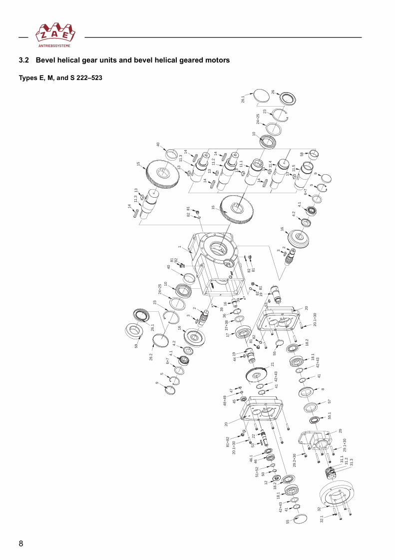
4. Condition on delivery and warrantyBefore being shipped, all ZAE gear units, ZAE geared motors, and worm gear setsundergo a final inspection and are checked to ensure that order requirements have beenmet. The gear units and geared motors are shipped with an epoxy resin-based primercoating in RAL 7035 (bright gray) and filled with oil unless otherwise stated.The vent filter and the coupling (only for types M and DM without motor) are supplied asloose parts in separate packaging.The individually shipped gear sets are coated with a corrosion inhibitor before beingpackaged.
ADuring the warranty period, ZAE gear units may only be opened with ourexpress permission; otherwise the warranty will be invalidated.
AAll instructions pertaining to use of the gear units and the geared motorsin potentially explosive gas and dust atmospheres (see 6.7, 7.5, 8.2, and9.3) must also be followed to ensure safe operation in a normal environ-ment as well as compliance with the warranty.
1 Housing 18 Bearing neck2.1 Hollow shaft 19 Pinion shaft2.2 Double-sided wheel shaft 20 Key2.3 Single-sided wheel shaft 21 Radial shaft seal2.4 Single-sided wheel shaft 22.1 Yoke (V design)3 Key 22.2 Yoke4 Key 23 Cheese head screw5.1 Bevel gear 24 Pinion shaft5.2 Bevel pinion 25 Tapered roller bearing6 Nilos ring 26 Support washer7 Deep groove ball bearing/tapered roller bearing 27 Retaining ring8 O-ring 28 Set of shim rings9 Set of shim rings 29 Support washer10 Annular cap 30 Retaining ring11.1 Cheese head screw 31 Radial shaft seal11.2 Lock washer 32.1 Intermediate flange12.1 Radial shaft seal 32.2 Cheese head screw12.2 Shaft cap 33 Support washer13.1 Countersunk screw 40.1 Coupling hub13.2 Countersunk washer 40.2 Ring gear14.1 Retaining ring 40.3 Coupling hub14.2 Set of shim rings 81 Threaded plug/vent plug16 Angular contact ball bearing/tapered roller bearing 82 Seal ring

18
5. Transportation and storagePlease check the shipment immediately upon receipt for any damage and to ensure thatall ordered parts have been received. Should any damage come to your notice, a dam-age claim must be completed in the presence of the forwarder. Please contact CustomerCare as soon as possible after completing the damage claim to determine what steps tofollow (see the last page for the appropriate phone number).If the gear unit or the geared motor is initially placed in temporary storage, the buildingused for storage should be dry and not subject to wide fluctuations in temperature to pre-vent condensation and any resulting corrosion.
6. Installation and commissioning
AAny work on gear units or geared motors must be carried out by autho-rized trained personnel only.
If any questions or problems arise during installation, we request that you contact ourCustomer Care (see the last page for the appropriate phone number).
Be sure to ensure that during installation of the ZAE gear units and geared motors, theexisting oil fittings, e.g., vents, control screw, and drain, are easily accessible. Provisionmust also be made for sufficient circulation of cool air. The gear unit must be installed inthe position specified in the order because only then is unhindered lubrication and airventing during operation ensured.As specified in statutory regulations, the user must ensure that all rotating parts are safe-guarded to prevent accidental contact with them.
6.1 Gear units and geared motors with projecting shaft endsDuring installation of a ZAE drive with a projecting shaft end, the gear unit is to be placedwith the machine to be driven on an appropriate base or foundation. Flange-mountedgear units can be attached directly to the machine to be driven.
AIn the interest of safe and quiet operation, the shafts must be very carefullyaligned. There should be no stresses on the housing or shafts. Use of flexiblecouplings to compensate for small amounts of misalignment is recommended.
6.2 Hollow shaft gear units and geared motorsZAE drives with hollow shafts can be placed directly on the shafts of the machines to bedriven. Axial fastening should be accomplished using an end washer and a screw if nofrictional shaft-hub locking device is used.
ACare should be taken to ensure that that the mounting surface lies at rightangles to the axle of the machine to be driven. Otherwise the unit bearing willbe overloaded and could break down prematurely. The reactive force corre-sponding to the output torque can be compensated for by a ZAE torquebracket. In order for additional bending stresses to be avoided, the torquebracket must always be situated on the machine side of the gear unit.
Mounting the gear unit directly to the base plate with the machine shaft alsomounted near the gear unit should be avoided under all circumstances.For frictional shaft-hub locking devices, never tighten the clamp bolts beforethe shaft has been installed because otherwise the hollow shaft may becomewarped.

19
6.3 Installing couplings or other componentsInstallation of couplings, sprockets, gear wheels, or pulleys, etc. should be performedwhile the components are warm or with the help of the thread centering device and ascrew. Ensure that there is axial support.
Before mounting, apply roller bearing grease to the gear tooth system of the ZAEmotor coupling.
ANever hammer supplementary parts onto the shafts because this may damagetooth profiles, roller bearings, and/or retaining rings.
6.4 Commissioning worm gear units and variantsUnless otherwise indicated in the order confirmation, ZAE worm gear units and variantsas well as ZAE geared motors are filled with synthetic lubricant at the factory. If deliveryof a gear unit without filling at the factory is requested, the unit should be filled using anoil grade matching the grade specified on the rating plate. When mineral oils are used,reduced performance should be taken into account. We ask that we be consulted beforeother oil grades are used. The correct oil level has been reached as soon as oil startsdripping out of the hole for the oil filler plug (E and M 100 to 400; GM 063 to 200; and E/M 012 to 513).For the correct lubricant amounts, please see the lubricant selection chart in Section 7.3.
AOn all gear units that have been filled with lubricant at the factory, first replacethe threaded plug with the enclosed vent filter, which should be uncontami-nated. A stopped-up vent causes internal pressure to increase and can possi-bly lead to leaks. For gear units delivered without oil fill ports, the vent filter isalready installed. Unit size 040 is delivered for all mounting positions in anenclosed version without a vent filter.
6.5 Commissioning bevel gear units and variantsUnless indicated otherwise in the confirmation of order, all ZAE bevel gear units are filledwith synthetic lubricant at the factory. If delivery of a gear unit without filling at the factoryis requested, the unit should be filled using an oil grade matching the grade specified onthe rating plate. Unit sizes 110 to 260 are equipped with oil filler plugs for checking the oillevel.For the necessary lubricant amounts, please see the lubricant selection chart in Section7.3.
AOn all gear units that have been filled with lubricant at the factory, first replacethe threaded plug with the enclosed vent filter, which should be uncontami-nated. A stopped-up vent causes internal pressure to increase and can possi-bly lead to leaks. For gear units delivered without oil fill ports, the vent filter isalready installed.
20
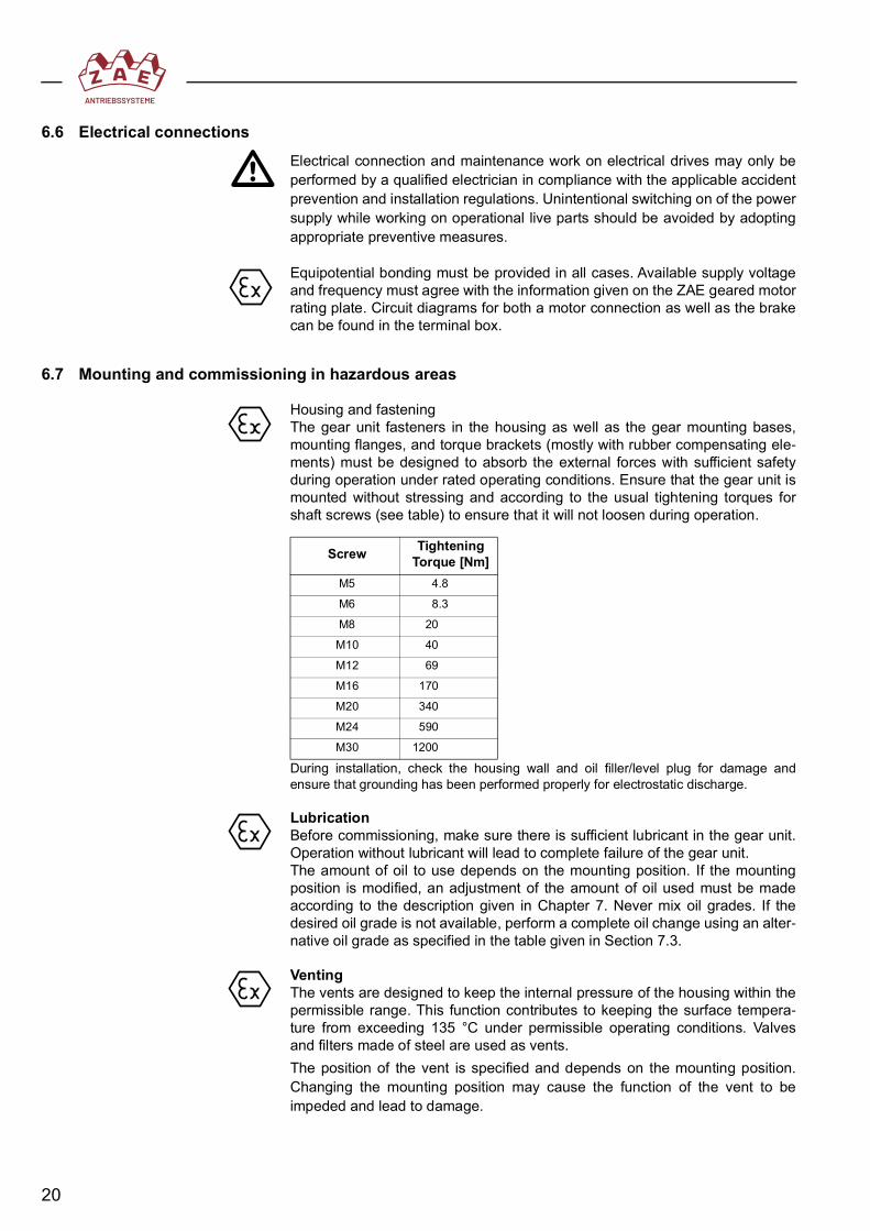
6.6 Electrical connections
AElectrical connection and maintenance work on electrical drives may only beperformed by a qualified electrician in compliance with the applicable accidentprevention and installation regulations. Unintentional switching on of the powersupply while working on operational live parts should be avoided by adoptingappropriate preventive measures.
Equipotential bonding must be provided in all cases. Available supply voltageand frequency must agree with the information given on the ZAE geared motorrating plate. Circuit diagrams for both a motor connection as well as the brakecan be found in the terminal box.
6.7 Mounting and commissioning in hazardous areas
Housing and fasteningThe gear unit fasteners in the housing as well as the gear mounting bases,mounting flanges, and torque brackets (mostly with rubber compensating ele-ments) must be designed to absorb the external forces with sufficient safetyduring operation under rated operating conditions. Ensure that the gear unit ismounted without stressing and according to the usual tightening torques forshaft screws (see table) to ensure that it will not loosen during operation.
During installation, check the housing wall and oil filler/level plug for damage andensure that grounding has been performed properly for electrostatic discharge.
LubricationBefore commissioning, make sure there is sufficient lubricant in the gear unit.Operation without lubricant will lead to complete failure of the gear unit. The amount of oil to use depends on the mounting position. If the mountingposition is modified, an adjustment of the amount of oil used must be madeaccording to the description given in Chapter 7. Never mix oil grades. If thedesired oil grade is not available, perform a complete oil change using an alter-native oil grade as specified in the table given in Section 7.3.
VentingThe vents are designed to keep the internal pressure of the housing within thepermissible range. This function contributes to keeping the surface tempera-ture from exceeding 135 °C under permissible operating conditions. Valvesand filters made of steel are used as vents.The position of the vent is specified and depends on the mounting position.Changing the mounting position may cause the function of the vent to beimpeded and lead to damage.
Screw Tightening Torque [Nm]
M5 4.8
M6 8.3
M8 20
M10 40
M12 69
M16 170
M20 340
M24 590
M30 1200

21
Leaving out a vent that has been designated as part of the design can onlytake place after the specific conditions of operation have been clarified andZAE consulted.During installation of a unit, care should be taken to ensure that the vent is notdamaged and its function is not impeded by dust or dirt. Faulty vents can leadto an increase in internal pressure in the housing and thus to increased tem-perature, which can result in damage.For gear units/geared motors delivered with oil fill ports, the vent is sealedwhen delivered. Prior to commissioning, the threaded screw must be removedand replaced by the vent, which is included as a separately packaged loosepart.
Sealing pointsCheck all dynamic sealing points between the shaft surfaces and the sealingedges immediately after commissioning to ensure that they exhibit tight sealsand are clean.
BearingsDue to installation errors, roller bearings may be subjected to considerableadditional forces that the bearing points are not designed to withstand. Thebearings could fail prematurely due to these additional forces.Therefore, ensure proper shaft alignment for all shaft connections. Unusualnoises and high temperatures may be indicative of bearings subjected tostresses.
Shafts and connectionsGear shafts may be subjected to additional bending, radial, and axial forcesdue to faulty installation. The shafts could break. Therefore, be sure that instal-lation is completed as specified. For form-fit shaft-hub connections, care should be taken to ensure that theconnections do not have too much play and are not too far out of alignment.Damage may result from impact forces, friction corrosion, or additional forcesthat cause the connection to fail. Spline shafts and key shafts are to begreased prior to installation to reduce corrosion-induced wear and prematurefailure.It is of vital importance that requirements regarding tolerances, surface quali-ties, and grease-free joints be met for frictional shaft-hub connections. Anappropriate glue must be used for glued-shrink-fit connections. ZAE is responsible for proper assembly of the connections inside the gear unit;please ensure that the connections on the outside of the gear unit are alsoassembled properly.
ZAE motor couplings and servo couplingsDuring installation of ZAE motor couplings, care should be taken to ensure thatthere is not too much play and no impermissible axial or radial misalignment.Damage may result from impact forces, friction corrosion, or additional forcesthat cause the coupling to fail.In addition, ensure that the teeth on the ZAE couplings have been lubri-cated with the appropriate grease prior to installation. The ZAE couplingsmust be secured axially on the motor shaft by stud bolts. The servo cou-plings must be secured by clamping screws tightened to the specifiedtightening torques.
Rotex GS Servo CouplingSize 19 24 28 38Tightening Torque [Nm] 10 10 25 49

22
Friction clutchesGear units with friction clutches are supplied with preset slip torques from thefactory. The slip torque setting may subsequently be adjusted. Constant slip-ping must be prevented by disabling mechanisms (also see 7.5).
Locking rings and frictional shaft-hub locking devicesNarrow, open gaps < 3 mm are to be avoided in areas exposed to dust. It is ofvital importance that requirements regarding tolerances, surface qualities, andgrease-free mounting surfaces be met for frictional locking rings and frictionalshaft-hub locking devices. The screws of the locking ring or the frictional shaft-hub locking device must be properly tightened to the specified torque value. Locking ring parts or frictional shaft-hub locking devices should not come intocontact with stationary parts.
Motors and brake motorsA mounted electric motor must be added by the manufacturer for categories2G and 2D and include a declaration of conformity and an EC type-examina-tion certificate. Damage to bearings, shafts, and couplings should be prevented throughmotors exhibiting reduced radial and axial runout in accordance with DIN42955 - R. Mounting must be performed according to the mounting guidelines.Provision must be made for equipotential bonding (grounding).
BrakesA mounted electric brake must be added by the manufacturer for categories2G and 2D and include a declaration of conformity and EC type-examinationcertificate.The brake and other attachments must be dimensioned adequately to ensurethat excessive mechanical and thermal loads can be ruled out during operationunder rated operating conditions. Uninterrupted brake disk dragging must beruled out by the operator.

23
Couplings used by the operatorElectrical couplings must be added by the manufacturer for categories 2G and2D and include a declaration of conformity and EC type-examination certifi-cate.Mechanical couplings must be delivered with a declaration of conformity.The operator must ensure that no contact with stationary parts will occur andthat the gap dimensions in areas exposed to dust are sufficiently wide (> 3mm). Coupling hubs must be secured axially; shaft alignment errors must beavoided. The couplings must be mounted in accordance with manufacturerinstructions.
Traction gearsTraction gears (chain, flat-, round-, and V-belt drives, and timing belt drives)must be delivered with the corresponding declaration of conformity for catego-ries 2G and 2D and require a CE marking.To prevent electrostatic discharge, belts must be manufactured using conduc-tive material. Ensure that no contact with stationary parts will occur and thatthe gap dimensions in areas exposed to dust are sufficiently wide (> 3 mm).Sprockets and belt pulleys must be secured axially. Shaft forces may notexceed the permissible force for the gear unit. Shaft, sprocket, and belt pulleymisalignment must be avoided.The traction gear units must be mounted in compliance with manufacturerinstructions.
Upstream and downstream gear unitsGear units mounted upstream or downstream of the ZAE gear unit must bedelivered with the appropriate declaration of conformity for categories 2G and2D and bear the CE marking.The shafts must meet the same radial and axial runout requirements as thoseapplicable to electric motors. The fastening connections must be tightenedusing the required torque and secured against unintentional loosening. Thejoint fasteners must be tightened to the specified torques and secured to pre-vent unintentional loosening. The gear units must be mounted in accordancewith manufacturer instructions.
Gear wheelsGear wheels attached to gear shafts must be dimensioned to ensure a suffi-cient degree of safety. Material and manufacturing quality must comply withrequirements. The operator must ensure that there is sufficient lubrication.In addition, it must be ensured that no contact with stationary parts will occurand that the gap dimensions in areas exposed to dust are sufficiently wide (> 3mm). Gear wheels must be secured axially. Shaft forces may not exceed thepermissible amount. Shaft and gear wheel misalignment must be avoided.
24
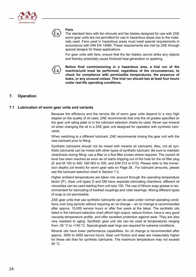
FansThe standard fans with fan shrouds and fan blades designed for use with ZAEworm gear units are not permitted for use in hazardous areas due to the mate-rials used. Fans used in hazardous areas must meet special requirements inaccordance with DIN EN 14986. These requirements are met by ZAE throughspecial designs for these applications.For gear units with fans, ensure that the fan blades cannot strike any objectsand thereby potentially cause frictional heat generation or sparking.
Before final commissioning in a hazardous area, a trial run of themachine/unit must be performed, regardless of the circumstances, tocheck for compliance with permissible temperatures, the presence ofleaks, or any unusual noises. This trial run should last at least four hoursunder real-life operating conditions.
7. Operation
7.1 Lubrication of worm gear units and variantsBecause the efficiency and the service life of worm gear units depend to a very highdegree on the quality of oil used, ZAE recommends that only the oil grades specified onthe gear unit rating plate or in the lubricant selection charts be used. Never use mineraloil when changing the oil in a ZAE gear unit designed for operation with synthetic lubri-cants.When switching to a different lubricant, ZAE recommends rinsing the gear unit with thenew lubricant prior to filling.Synthetic lubricants should not be mixed with mineral oil lubricants. Also, not all syn-thetic lubricants can be mixed with other types of synthetic lubricant. Be sure to maintaincleanliness during filling; use a filter or a fine filter screen where required. The correct oillevel has been reached as soon as oil starts dripping out of the hole for the oil filler plug(E and M 100 to 400; GM 063 to 200; and E/M 012 to 513). Please refer to the immer-sion depths (oil levels) for worm gear sets on Page 26.. For lubricant amounts, pleasesee the lubricant selection chart in Section 7.3.Higher ambient temperatures are taken into account through the operating temperaturefactor (fT). Gear unit types D and DM have separate lubricating chambers; different oilviscosities can be used starting from unit size 100. The use of lithium soap grease is rec-ommended for lubricating of toothed couplings and roller bearings. Mixing different typesof soap is not permissible.ZAE gear units that use synthetic lubricants can be used under normal operating condi-tions over long periods without requiring an oil change – an oil change is recommendedafter approx. 15,000 service hours or after five years at the latest. The synthetic oilslisted in the lubricant selection chart afford high output, reduce friction, have a very goodviscosity-temperature profile, and offer excellent protection against wear. They are alsovery resistant to aging. Synthetic gear unit oils can be used at temperatures rangingfrom -30 °C to +140 °C. Special-grade seal rings are required for extreme conditions.Mineral oils have lower performance capabilities. An oil change is recommended afterapprox. 3000 to 4000 service hours. Gear unit friction and wear are measurably higherfor these oils than for synthetic lubricants. The maximum temperature may not exceed90 °C.

25
The gear unit should be checked at lengthy intervals for oil loss. If the oil has to betopped up, one of the synthetic lubricants specified on the rating plate should be used.The required oil viscosity varies depending on speed. This applies equally to polyglycols,polyalphaolefins, ester oils, and mineral oils:
7.1.1 Lubricant amountsLubricant amounts in liters (dm3)
Worm gear unit types E and M and servo gear unit type S
Worm helical gear unit types E and M
Duplex worm gear unit types D and DMHere, the amounts for the first and second stages must be added together.
Worm Shaft Speed (min-1) Oil Viscosity (ISO VG)
From To
1500 3000 220
300 1500 460
300 680
Mounting PositionSize 1 2 3 + 4 5 + 6040 0.2 0.25 0.2 0.2050 0.3 0.6 0.45 0.45063 0.6 1.1 0.7 0.8080 1.0 2.1 1.4 1.6100 1.6 4.2 3.4 2.8125 2.6 7.0 5.0 4.1140 2.9 7.8 5.2 4.8160 4.3 15.0 9.5 8.4175 5.9 16.1 11.0 10.0200 8.0 28.0 18.0 16.0250 14.0 44.0 28.0 22.0315 19.0 – – 45.0400 20 150 85 85
Mounting PositionSize 1 2 3 4 5 + 6012 0.85 0.85 0.85 0.85 1.1112/113 1.4 2.0 1.9 1.6 2.4212/213 3.5 3.8 3.6 3.8 4.1312/313 5.2 6.0 5.2 5.2 8.0512/513 17.0 19.0 19.0 18.0 25.0

26
Helical worm gear unit types GE and GM
The lubricant amounts specified apply to the mounting positions and ratios for which thegreatest amounts of oil are required. The oil level screw (oil filler plug) is the measuringpoint in all cases; the correct oil level must be checked using the oil level screw.
Oil level for worm gear setsThe following table contains the recommended oil levels for immersion lubrication. Besure that there is sufficient lubrication of the bearings lying above the oil level.Oil level in the unit during immersion lubrication:
Minimum required oil amountTo prevent premature aging due to contamination and heating of the unit oil, amountsshould not fall below the following oil levels during immersion lubrication:
Mounting PositionSize 1 2 3 4 5 + 6050 0.5 1.0 1.0 1.0 0.8063 0.8 1.5 1.5 1.8 1.2080 1.3 2.5 2.5 3.2 2.0100 2.5 5.5 5.5 6.9 3.75125 4.3 8.2 8.2 8.9 5.5200 11.2 31.5 25.5 35.5 21.5
1 2 3 4 5 6
Gear Set Size Minimum Amount of Oil in Gear Unit
dm3
Gear Set Size Minimum Amount of Oil in Gear Unit
dm3
040 0.2 125 2.5
050 0.3 160 4.25
063 0.5 200 7.6
080 0.9 250 13.0
100 1.5 315 19.0

27
7.1.2 Mounting positions for vent filters and oil fittings
Worm gear units and worm gear motors E/M/S 40–80
B
F
øD
E
B
EE
CBA A
A E
Mounting position1
Mounting position2 3
Mounting position
Mounting position Mounting position Mounting position
4 5 6
Size A B C D E F
040 – – – – – –
050 50 20 33 22 58 25
063 62.5 27.5 37 22 67 25
080 77.5 32.5 57 22 82 25
Size 040 without vent= vent filter
28
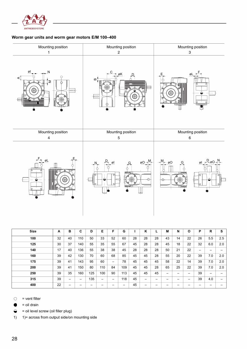
Worm gear units and worm gear motors E/M 100–400
DMøO øO GMGøIF
øIøK D EC
N øI
A B
øL
øL EøO
F
D N
N
MMounting position
1Mounting position
2 3Mounting position
Mounting position Mounting position Mounting position
4 5 6
Size A B C D E F G I K L M N O P R S
100 32 40 110 50 33 52 60 28 28 28 43 14 22 26 5.5 2.5
125 30 37 140 55 35 55 67 45 28 28 45 18 22 32 6.0 2.0
140 17 40 136 55 38 38 45 28 28 28 50 21 22 – – –
160 39 42 130 70 60 68 85 45 45 28 55 20 22 39 7.0 2.0
175 39 41 143 95 60 – 78 45 45 45 58 22 14 39 7.0 2.0
200 39 41 150 80 110 84 109 45 45 28 65 25 22 39 7.0 2.0
250 39 35 160 125 100 90 113 45 45 45 – – – 39 – –
315 39 – – 135 – – 118 45 – – – – – 39 4.0 –
400 22 – – – – – – 45 – – – – – – – –
= vent filter= oil drain= oil level screw (oil filler plug)
1) 1)= across from output side/on mounting side
29
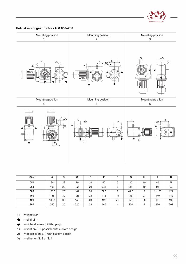
Helical worm gear motors GM 050–200
3)2)
1)K C K
EG
A
B F
H B B
C E BøD øD
øD
I
øD CøD øD
Mounting position1
Mounting position2 3
Mounting position
Mounting position Mounting position Mounting position
4 5 6
Size A B C D E F G H I K
050 98 23 70 20 62 6 25 10 80 78
063 105 23 82 20 69.5 6 35 10 92 93
080 126.5 23 102 20 79.5 7 42.5 5 111.25 124
100 155 30 123 28 112 18 33 27 140 142
125 188.5 30 145 28 122 21 55 30 161 190
200 260 25 225 28 145 – 130 5 260 301
= vent filter= oil drain= oil level screw (oil filler plug)
1) = vent on S. 3 possible with custom design2) = possible on S. 1 with custom design3) = either on S. 2 or S. 4

30
Worm helical gear units and worm helical geared motors E/M 112/113–212/213
1)
C
K
L
A
B
K
E
G
K
C
I
G
C
CKH
G
F
I
G
G
A
F
G
I
E
GF
L
A56,8
H
F
H
C K
D
L
Mounting position1
Mounting position2 3
Mounting position
Mounting position Mounting position Mounting position
4 5 6
Vent filter:
Size A B C D E F G H I K L
112/113 15 25 88 22 40.5 70 36.5 35 55 25 25
212/213 -17.5 25 146.5 22 50 72 40 -85 65 25 77.5
Size 012 without vent1) = across from drive side
= vent filter= oil drain= oil level screw (oil filler plug)

31
Worm helical gear units and worm helical geared motors E/M 312/313–512/513
1)
KL
B
AC
L E
G
E
H
A H
A
F
G
I
G
E
G
CK
F
C
C
G
H
I LG
F
H G
CK
K
K
D
I
Mounting position1
Mounting position2 3
Mounting position
Mounting position Mounting position Mounting position
4 5 6
Vent filter:
Size A B C D E F G H I K L
312/313 20 32 153 28 80 65 55 95 80 30 75
512/513 20 32 225 28 82.5 110 77.5 115 115 50 90
1) = across from drive side= vent filter= oil drain= oil level screw (oil filler plug)

32
7.2 Lubrication of bevel gear units and variantsLubrication instructions must be precisely followed. Performing maintenance on a regu-lar basis will ensure the highest degree of operational safety and result in a long servicelife for your gear unit. Never use mineral oil when changing the oil in a ZAE gear unitdesigned for operation with synthetic lubricants. The same thing applies to the reversecase.Synthetic lubricants should not be mixed with mineral oil lubricants. Also, not all syn-thetic lubricants can be mixed with other types of synthetic lubricant. Be sure to maintaincleanliness during filling; use a filter or a fine filter screen where required. The correct oillevel has been reached as soon as oil starts dripping out of the hole for the oil filler plug(W and MW 110 to 260; E and M 222 to 523).ZAE gear units that use synthetic lubricants can be used under normal operating condi-tions over long periods without requiring an oil change – an oil change is recommendedafter approx. 15,000 service hours or after five years at the latest. The synthetic oilslisted in the lubricant selection chart afford high output, reduce friction, have a very goodviscosity-temperature profile, and offer excellent protection against wear. They are alsovery resistant to aging. Synthetic gear unit oils can be used at temperatures rangingfrom -30 °C to +140 °C. Special-grade seal rings are required for extreme conditions.Mineral oils have lower performance capabilities. An oil change is recommended afterapprox. 3000 to 4000 service hours. Gear unit friction and wear are measurably higherfor these oils than for synthetic lubricants. The maximum temperature may not exceed90 °C.The gear unit should be checked at lengthy intervals for oil loss. If the oil has to betopped up, one of the synthetic lubricants specified on the rating plate should be used.The required oil viscosity varies depending on speed. This applies equally to polyglycols,polyalphaolefins, ester oils, and mineral oils:
Bevel helical gear unit types E/M/S 222–523 are usually filled with ISO VG 220 lubri-cants.
Speed of High-Speed Shaft in min-1 Gear Unit Size and ISO VG Lubricant Viscosity
From To 088 110 136 156 199 2602000 3000
1001500 2000
1000 1500
220
750 1000
500 750
250 500
To 250

33
7.2.1 Lubricant amounts
Bevel gear units and bevel geared motor types W, MW, and SW
The lubricant amounts specified apply to the mounting positions and ratios for which thegreatest amounts of oil are required. The oil level screw (oil filler plug) is the measuringpoint in all cases; the correct oil level must be checked using the oil level screw.
Bevel helical gear unit types E, M, and S
Gear Size 088 110 136 156 199 260Approx. Filling Amount (in Liters)
0.15 0.3 0.55 0.75 2.2 4.5
Mounting PositionSize 1 2 3 4 5 6222 2.1 2.4 2.9 3.5 2.4 1.8322 4.5 5.3 5.8 8.4 5.3 4.4422 7.2 8.0 8.9 12.1 8.5 8.2522 13.5 15.6 17.5 23.9 15.4 13.4223 2.0 2.3 2.7 3.3 2.3 1.7323 4.3 5.0 5.5 8.0 5.0 4.2423 6.9 7.6 8.5 11.5 8.1 7.8523 12.9 14.9 16.7 22.8 14.7 12.8

34
7.2.2 Mounting positions for vent filters and oil fittings
Bevel gear units and bevel geared motor types W, MW, and SW 110–260
Size A B C D D1 F G
110 20 19.5 20 22 13.2 23 11
136 25 26 25 28 13.2 22 15.5
156 26 26 26 28 22 24.5 17
199 28 26 28 28 28 35.5 20
260 28 26 28 28 28 35.5 25
= vent filter= oil drain= oil level screw (oil filler plug)
X = position of vent filter for design type 0002
A
øD
B
W 136, W 156,W 199, W 260
W 110
C
øD 1
F
G GX
Mounting position1
Mounting position2
Mounting position3
Mounting position4
Mounting position5
Mounting position6

35
Bevel helical gear units and bevel helical geared motors E/M/S 222–523
A1
A
A
AD
E
C
C
F
BB
G
A
Ea
B
E G
F
B
A
D
G
D
G D
F
E
F
Mounting position1
Mounting position2
Mounting position3
Mounting position4
Mounting position5
Mounting position6
Size A B C D D1 F G
110 20 19.5 20 22 13.2 23 11
136 25 26 25 28 13.2 22 15.5
156 26 26 26 28 22 24.5 17
199 28 26 28 28 28 35.5 20
260 28 26 28 28 28 35.5 25
= vent filter= oil drain= oil level screw (oil filler plug)
X = position of vent filter for design type 0002a = on the back

36
7.3 Lubricants and manufacturers
Lubricant type Quality/ISO VG
H2 lubricants (standard industrial lubricants)
Mineral oils
CLP 100 Alpha SP 100 Optigear1100/100
RenolinCLP 100
Klüberoil GEM 1-100 N
Mobilgear 600 XP 100
OmalaS2 G 100
CLP 220 Alpha SP 220 Optigear1100/220
RenolinCLP 220
Klüberoil GEM 1-220 N
Mobilgear 600 XP 100
Omala S2 G 220
CLP 460 Alpha SP 460 Optigear1100/460
RenolinCLP 460
Klüberoil GEM 1-460 N
Mobilgear 600 XP 100
Omala S2 G 460
CLP 680 Alpha SP 680 Optigear1100/680
RenolinCLP 680
Klüberoil GEM 1-680 N
Mobilgear 600 XP 100
Omala S2 G 680
Poly-α-olefins
CLP HC 100 - - Renolin Unisyn CLP 100
Klübersynth GEM 4-100 N
- OmalaS4 GX 100
CLP HC 220 AlphasynEP 220
OptigearSynthetic PD 220
Renolin Unisyn CLP 220
Klübersynth GEM 4-100 N
Mobil SHC Gear 220
OmalaS4 GX 220
CLP HC 460 AlphasynEP 460
OptigearSynthetic PD 460
Renolin Unisyn CLP 460
Klübersynth GEM 4-100 N
Mobil SHC Gear 460
OmalaS4 GX 460
CLP HC 680 AlphasynEP 680
OptigearSynthetic PD 680
Renolin Unisyn CLP 680
Klübersynth GEM 4-100 N
Mobil SHC Gear 680
OmalaS4 GX 680
Esters
CLP E 100 - - - KlüberbioCA 2-100
- -
CLP E 220 Performance BioGE 220 ESS
-Plantogear 220 S
Klübersynth GEM 2-220 -
Naturelle Gear Fluid EP 220
CLP E 460 - - Plantogear 460 S
KlüberbioCA 2-460
- Naturelle Gear Fluid EP 460
CLP E 680 - - - - - -
Polyglycols
CLP PG 100-
OptigearSynthetic 800/100
Renolin PG 100 Klübersynth GH 6-100
Glygoyle 100-
CLP PG 220 AlphasynPG 220
OptigearSynthetic 800/220
Renolin PG 220 Klübersynth GH 6-220
Glygoyle 220 OmalaS4 WE 220
CLP PG 460 AlphasynPG 460
OptigearSynthetic 800/460
Renolin PG 460 Klübersynth GH 6-460
Glygoyle 460 OmalaS4 WE 460
CLP PG 680 AlphasynPG 680
OptigearSynthetic 800/680
Renolin PG 680 Klübersynth GH 6-680
Glygoyle 680 OmalaS4 WE 680
Greases(roller bearings + radial shaft seals)
SpheerolEPL 2
Tribol GR100-2 PD
RENOLITLZR 2 H
CENTOPLEX2 EP
Mobilgrease XHP 222
Gadus S2V220 2
H1 lubricants (NSF-registered products for the food industry)
Poly-α-olefins
CLP HC 100 - OptilebGT 100
CassidaHF 100
Klüberoil4 UH1-100 N
- -
CLP HC 220 - OptilebGT 220
CassidaHF 220
Klüberoil4 UH1-220 N
Mobil SHC Cibus 220
-
CLP HC 460 - OptilebGT 460
CassidaHF 460
Klüberoil4 UH1-460 N
Mobil SHC Cibus 460
-
CLP HC 680 - OptilebGT 680
CassidaHF 680
Klüberoil4 UH1-680 N
Mobil SHC Cibus 680
-

37
Due to limited space, not all products are listed in the table. Lubricants from other manu-facturers such as Total, Lubcon, or Bechem or alternative products from the listed man-ufacturers can be requested from ZAE-AntriebsSysteme or the respective lubricant pro-ducers. If in doubt about use of alternative products in ZAE gear units, please consultZAE-AntriebsSysteme to avoid problems.
7.4 TroubleshootingIf you detect any malfunctions during operation, please try to determine what types ofmalfunctions are present and remedy them with the help of the following guide. If youare not able to eliminate the malfunction, please contact Customer Care (see backcover).
See the back cover of the manual for customer care contact details
Polyglycols
CLP PG 100 - - - Klübersynth UH1 6-100
- -
CLP PG 220 - Optileb GT1800/220
CassidaWG 220
Klübersynth UH1 6-220
Glygoyle 220 -
CLP PG 460 - Optileb GT1800/460
CassidaWG 460
Klübersynth UH1 6-460
Glygoyle 460 -
CLP PG 680 - Optileb GT1800/680
CassidaWG 680
Klübersynth UH1 6-680
Glygoyle 680 -
Greases(roller bearings +radial shaft seals)
-Optileb GRUF 2 -
Klübersynth UH1 14-222
Mobilgrease FM 222 -
Symptom Possible cause RemedyOil is leaking:• On the drive side of
the shaft seal ring• On the output side of
the shaft seal ring• On the gear unit cap• On the motor flange• On the motor shaft seal
ring
A Shaft seal ring defective or shaft damaged
B O-ring on gear unit cap leak-ing
C Surface seal damagedD Gear unit not bled
A + BCall Customer Care
C Tighten screws on gear unit cap and observe gear unitIf oil continues to leak:call Customer Care
D Vent gear unit
Oil is leaking from the air bleed valve
A Too much oil in gear unitB Drive inserted in wrong
mounting position/air bleed valve in wrong position
C Frequent cold start (oil foams)
A Correct the amount of oil(see 7)
B Mount air bleed valve cor-rectly (see designs) and correct oil level
C Check oil viscosity and oil level
Unusual, constantrunning noise
A Meshing/grinding noise: bearing damage
B Knocking noise:irregularity in gear toothing
A + BCheck oil, change bearing, call Customer Care
Unusual, irregular running noise
Foreign substances in oil Check oil, shut down gear unit, call Customer Care
Unusually high housing tem-peratures
A Insufficient oilB Gear tooth system or bearing
defective
A Check oil level/correctB Call Customer Care
Output shaft is not rotating even though motor is running or drive shaft is being rotated
Shaft-hub connection orgear tooth system broken
Send in gear unit/gear unit motor for repair

38
7.5 Operation in hazardous areas
Gear unit housing, gear mounting bases, and mounting flangeThe components are designed so that internal and external forces occurringduring operation under rated operating conditions can be absorbed with a suf-ficient level of safety. Unit thermal performance has been designed so that sur-face temperatures do not exceed 135 °C under permissible operating condi-tions at a maximum ambient temperature of 40 °C.The thermal limits as well as the maximum circumferential speeds of toothedwheels and shafts under radial shaft seals are taken into account in the speci-fied performance data. This serves to prevent damage due to thermal over-loading and insufficient lubrication.Our ZAE catalog contains design guidelines, including rated data T2perm. andoperating factors (fOM, fSF, fT, fON), which must be observed by the operator.Be sure that there is no excessive loading and that any damages (e.g., cracks)in the housing wall are detected in a timely manner by conducting regularinspections. Additional holes drilled in the housing wall at a later time must beappropriately secured. Also make sure that no fasteners come loose or aredamaged on the cover locks during operation.
Torque supportsThe torque supports are designed so that external forces occurring duringoperation under rated operating conditions can be absorbed with a sufficientlevel of safety; their surfaces reach the maximum housing temperature.Make sure that no overloading occurs, the fasteners remain tight during opera-tion, and the compensation bushings perform their compensating function.
Static sealsThe seals can be damaged due to mechanical, thermal, or chemical factors ordue to loosening of mounting elements such as screws and retaining rings andtherefore stop working; lubricant may leak out.If lubricant is lost due to improper use or overloading, excessive temperatureswill occur and moving parts in the gear unit will be damaged.
Dynamic sealsAll seals (radial shaft seals) are mounted in accordance with manufacturerinstructions. The designated operating conditions also comply with manufac-turer instructions. Guidelines for sealing edge overtemperature are given bythe manufacturer and state that for shaft speeds of up to 3000 min-1, the over-temperature of the sealing edge with respect to the oil sump will not exceed 40K if the housing is vented and the seal ring is sufficiently lubricated. Dynamicseals are wear parts for which there is currently no definitive information onservice life available.During operation the sealing point/surface (radial shaft seal/shaft surface) canbecome damaged internally and externally due to the effects of force, acids,basic solutions, solvents, certain oils, and UV rays as well as dust and dirt.Excessively high temperatures and corrosion during operation can also causedamage to the sealing points (surfaces).During operation be sure to check that sealing points/surfaces are clean andfree of damage.

39
VentsThe vents are designed to keep the internal pressure of the housing within thepermissible range. This function contributes to keeping the surface tempera-ture from exceeding 135 °C under permissible operating conditions. Leavingout a vent that has been designated as part of the design can only take placeafter the specific conditions of operation have been clarified and ZAE con-sulted.
BearingsAll roller bearings must have oil or lifetime grease lubrication. Additional load-ing can be avoided through following of all roller bearing manufacturer instruc-tions and optimal bearing arrangement and adjustment. The calculated servicelife for these conditions is at least 8000 hours for all gear units. After that, thebearings must be inspected and may need to be replaced.The surface temperatures in the bearing regions cannot exceed 135 °C underthe permissible service conditions at an ambient temperature of 40 °C. In addi-tion, the bearings on the fast-running drive side are cooled by the oil.Continuous or intermittent torsional load spikes can lead to premature failure ofa roller bearing. Lateral forces introduced via shafts from the outside bywheels, friction rollers, gear wheels, or pulleys may also damage the bearings.Take measures to ensure that the gear unit is not exposed to loads in excessof the allowable loads specified by the manufacturer.Dust and dirt from the outside or inside can also damage the roller bearings.
Shafts and shaft-hub connectionsNo additional heat is generated by the shaft-hub connection. The shafts aredesigned for long-term operation under the rated conditions. Failure of thematerial used to make the shaft is not to be expected under the permissibleservice load conditions.The operator must ensure that no overloads, torsional load spikes, or addi-tional radial loads (e.g., from attached wheels, friction rollers, gear wheels, orpulleys) exceeding allowable levels occur.The form-fit shaft-hub connections (keys, spline shafts, fitting screws, andlocating pins) are designed for long-term operation under the rated conditions.Care should be taken to ensure that the spline and key shafts are sufficientlylubricated and that overloads due to periodic or constant torsional load spikes,resulting in excessive shear and compressive stresses, are avoided.The interference-fit shaft-hub connections (longitudinal and transverse press-fit connections, glue shrink-fit connections) are designed for long-term opera-tion under the rated conditions.A single instance of torsional overloading of an interference-fit shaft-hub con-nection can dramatically reduce the transmittable torque. Additional axial andbending loads also reduce the resistance of the connection.It must be ensured that permissible torque values and forces are notexceeded.
ZAE motor couplings and servo couplingsThe ZAE coupling includes both form-fit and interference-fit connections and isdurably designed. If required, the interference-fit connection can be secured bypins.

40
Intermittent or continuous torsional load spikes may lead to the failure of a ZAEmotor coupling due to excessive shear and compressive stresses. Be sure toavoid overloading due to impermissibly high torques.The servo couplings used by ZAE have type-examination certification for usein categories 2G and 2D.
Friction clutchesNo additional heat is generated by the friction clutch as long as it is not perma-nently applied. Only if the set torque is exceeded do relative movements occur,generating additional heat.Constant slipping must be prevented when a friction clutch is used. This canbe achieved through temperature and slip monitoring and appropriate shutoffmechanisms.Repeated occurrence of torque overload or constant torque overload of a fric-tion coupling can reduce the transmittable torque.Ensure that the permissible torque values are not exceeded and that the cou-pling is correctly set.
Locking rings and frictional shaft-hub locking devicesNo additional heat is generated by the locking rings or frictional shaft-hub lock-ing devices. The connections are durably designed for long-term operationunder rated conditions. Constant slipping can result in considerable heatbuildup. The locking ring parts should not come into contact with stationaryparts. Narrow, open gaps must be prevented in dusty areas. Locking ringsmust be covered using suitable design measures.A single instance of torsional overloading of a frictional locking ring or a fric-tional shaft-hub locking device can dramatically reduce the transmittabletorque. Additional axial and bending loads also reduce the resistance of theconnection.Ensure that the permissible torque values and forces are not exceeded.
Gear wheelsThe calculated service life under rated torque conditions is at least 12,000hours. After that, the gear sets must be checked and, if necessary, replaced.Failure of the gear wheel material is not to be expected under the permissibleservice load conditions.Intermittent or continuous torsional load spikes may lead to failure of toothflank faces or roots. If no break occurs during overloading, at least a tempera-ture rise is to be expected.Be sure to avoid overloading, especially due to impermissibly high torques.
LubricantsGear units for use in potentially explosive atmospheres may only be filled withsynthetic polyglycol-based oils. The flash point is generally above 250 °C forthe recommended lubricants. Certain types of lubricant are recommended andthe lubricant amounts specified for this type of application.The recommended lubricants are equally appropriate for lubricating gear toothsystems, roller bearings, and seals. Lubricants undergo an aging process andbecome increasingly contaminated over the course of their service lives. Thisdegrades the lubricant properties. For this reason, lubricants can only be usedfor a limited period and must be changed at given intervals. The maximum
41
useful life depends on the type of lubricant and the service demands made onthe lubricant; however, it is at least 15,000 service hours. The lubricant mustbe changed after this period or after five years at the latest.The type of lubricant used plays a decisive role in temperature and wearbehavior.Lubricants based on different substances or from different suppliers may notbe mixed. The base oils, additives, and thickeners may be incompatible withone another and seriously degrade the properties of the lubricant.When adding lubricant, only use the lubricant stated on the rating plate. Whenswitching to a new lubricant during an oil change, first rinse the gear unit hous-ing with the new lubricant.It is the responsibility of the operator to use an appropriate lubricant. Recom-mendations can be found in Section 7.3.
8. Inspection and maintenance
8.1 General informationA ZAE gear unit will run reliably for many years under rated operating conditions. Aftercommissioning, the gear unit should still be checked, cleaned, and serviced at regularintervals.The intervals for inspection and maintenance are highly dependent on the application: adrive that is only required for occasional positioning tasks in a clean environment atroom temperature requires less effort than a drive being used at high temperatures inthree-shift operations involving a dirty environment.Inspection and maintenance intervals will normally be the same as the intervals speci-fied by the manufacturer for the entire machine or unit. In some applications, sensors aredeployed on the drives to continuously monitor the condition (current consumption,torque values, temperatures, and vibrations).
In any case, a drive should be checked and maintained on a regular basis. The followingchecks should be made in the process:• Contamination• Condition of housing, covers, and fasteners• Condition and function of vents• Seal ring and cover leaks• Bearing noise• Gear tooth system noise• Shaft-hub connections and couplings• Temperature on the housing surface• Oil dripping and oil level• Overall condition of lubricant (oil samples)• Motor noise and current consumption• Recommended oil change intervals
These measures ensure the operational capability of your machine or assembly unit,prevent unexpected malfunctions, and minimize the risk of accidents.
42
8.2 Inspection and maintenance in hazardous areas
Gear unit housingPerform regular checks to ensure that the fasteners on the gear housing andthe cover locks are not loose or damaged and that any cracks in the housingwall resulting from overloading or extreme shocks are detected in a timelymanner. In addition, care should be exercised that the oil level screw is notexposed to force and that any damage is detected in a timely manner becausefailure to detect this may lead to loss of oil.Dust and layers of dirt on the housing surface may interfere with heat dissipa-tion and thus cause impermissible temperature buildup.Ensure that surfaces are checked and cleaned at regular intervals.
The ingress of dust and dirt into the housing will impair the lubricating perfor-mance and lead to damage of the moving parts; this will lead to wear and anincrease in temperature.Take appropriate measures to ensure that no dust or dirt enters the housingduring maintenance work or cleaning. If contamination is suspected, at leastthe lubricant should be changed, the temperature checked, and a check forgear unit noise made. If a large quantity of foreign substances enters the gearunit, the unit must be cleaned or replaced by a qualified specialist.
There should be no oil leaking out of the housing during normal operation. Ifimproper operation or overloading causes there to be loss of lubricant, this willcause overheating and damage to moving parts.Monitor and inspect the housing on a regular basis to detect and stop anylubricant leaks. If a significant loss of lubricant is suspected, the cause of theleak should be eliminated, the specified lubricant added, the temperaturechecked, and gear unit noise checked.
Gear mounting bases, mounting flanges, and torque supportsEnsure that no overloading of the gear mounting bases, the mounting flanges,or the torque supports (or their compensating bushings) occurs and that anypart damage is detected in a timely manner by performing inspections on aregular basis.
SealsThe elastomeric materials of the seal rings are not resistant to some gear unitoils and greases. These oils and greases should not be used; otherwise dam-age to the elastomer will result.Only lubricants specified on the rating plate or given in the manufacturer spec-ifications may be used.Take appropriate measures and perform regular checks to ensure that sealingpoints keep functioning (cleanliness of the sealing point, no insufficient lubrica-tion due to loss of oil) and that any lubricant leaks are detected in a timelymanner. If a significant loss of lubricant is suspected, the cause of the leakshould be eliminated, the specified lubricant added, the temperature checked,and gear unit noise checked.Lubricants may only be added by specialized personnel.

43
VentsThe effects of force, excessive lubrication or the wrong type of lubricant, ordust and dirt may impair the vent function, causing the internal housing pres-sure to increase and the temperature to rise accordingly.Ensure that the vent is free of damage and operational and perform regularchecks for contamination and any lubricant leakage. If a significant loss oflubricant is suspected, the cause of the leak should be eliminated, the speci-fied lubricant added, the temperature checked, and gear unit noise checked.
BearingsEnsure that the loads on the gear unit comply with the permissible loads spec-ified by the manufacturer. Performing regular checks of temperature, noise,and lubrication will prevent sudden failure. Replacement is recommended afterthe service life has been reached. Roller bearing repairs may only be per-formed by specialized personnel.
Gear shaftsThe gear shafts may not be subjected to overloading conditions. Be sure thatany cracks in the shaft resulting from overloading are detected in a timely man-ner by performing regular inspections.
Shaft-hub connectionsOverloading due to impermissibly high torque values is to be avoided for allshaft-hub connections (form-fit and interference-fit connections). In addition,make certain that form-fit connections are sufficiently greased and that a checkis regularly made of the greasing. Shaft-hub connections must be regularlychecked for unacceptable play and to determine transmittable torque values.
ZAE motor couplingsEnsure that overloading resulting from impermissibly high torque values isavoided and perform regular checks of the greasing completed during installa-tion.ZAE motor couplings must be regularly checked for unacceptable play anddamages and to ensure reliable torque transmission.
Friction clutchesFriction couplings must be checked on a regular basis to determine transmitta-ble torque values. Any existing slip or temperature monitoring system mustalso be checked regularly to ensure proper function.
Gear wheelsEnsure that the maximum loads on the gear unit comply with the permissibleloads specified by the manufacturer. Performing regular checks of tempera-ture, noise, and lubrication will prevent sudden failure. Replacement is recom-mended after the service life has been reached. Repairs may only be per-formed by specialized personnel.Only lubricants specified on the rating plate or given in the manufacturer spec-ifications may be used. Lubricants may only be changed and/or added by spe-cialized personnel.

44
LubricantsOnly lubricants specified on the rating plate or given in the manufacturer spec-ifications may be used. Ensure that the amount is adequate. Regular inspec-tion of the lubricant amount and the sealing points is recommended.Lubricants may only be changed and/or added by specialized personnel.Please see 7. for recommended change intervals.
Dust, dirt, and water in the lubricant can severely impair the lubrication of themoving parts.Make sure that no excessive dust or dirt deposits collect at sealing points orvents. There should be no ingress of dust, dirt, or water into the gear unit.When cleaning the unit, make sure not to point any high-velocity cleaning jetsdirectly at seals or vents. The operator must perform regular checks to ensurethat sealing points and vents remain free of damage. A defective sealing pointor vent must be assessed and repaired or replaced by qualified personnel.
Perform inspections on a regular basis to ensure that any lubricant leakage isdetected and eliminated in a timely manner. If a significant loss of lubricant isdetected, the specified lubricant should be added, the temperature checked,and gear unit noise checked.Lubricants based on different substances or from different suppliers may notbe mixed. The base oils, additives, and thickeners may be incompatible withone another and seriously degrade the properties of the lubricant.When switching to a new lubricant during an oil change, first rinse the gear unithousing with the new lubricant.
FansCheck and clean the gear unit fans on a regular basis because dust and dirtdeposits in a fan reduce its cooling performance and may lead to unacceptableheat buildup due to friction.

45
9. Electric motors
9.1 Brake motorsBrake motors are equipped with spring-applied brakes (mounted between motor endshield and fan blade) underneath the fan shroud. When the motor is started the brake issupplied with DC voltage via an appropriate rectifier.The spring-applied brake is an electromagnetic power off brake consisting of a magnet(1), an armature disk (2), and a brake rotor (3). It is fastened with screws (4) to the endshield (5) and enclosed in a fan shroud (6). The motor end shield serves as a brakingsurface. In a current-free condition, the compression springs (7) press the armature disk(2) against the brake rotor (3) and the brake rotor against the motor end shield (5). Brak-ing torque is produced on both friction surfaces by a frictional clamping force. When themotor is started the magnet coil is excited and the magnet (1) attracts the armature disk(2) with a magnetic force that opposes the spring force. The brake rotor (3) is released.Braking torque can be reduced by a maximum of 40% by means of the adjustment ring(8).
Manual release knobThe manual release knob is used to release the brakes manually and is available as anaccessory.
1 Magnet 4 Screws 7 Compression spring2 Armature disk 5 End shield 8 Self-aligning ring3 Brake rotor 6 Fan shroud 9 Manual release knob
SLü
4
1
786
5
2
3
9

46
Braking voltage assignmentBraking voltage is normally designed to match the motor delta voltage (i.e., motor 230/400 V
/ = brake coil control 230 V AC).For motors that use star-delta starting and on pole-changing motors, the braking voltageis designed according to the phase voltage of the main power supply from the grid.
Air gapThe air gap Ga should be checked from time to time. Wear on the surfaces of the rotorsubjected to friction depends upon the masses to be braked, the rotational speeds, andthe frequency of switching. Upon reaching Ga max. (see table), adjust the air gap to Ga.
Special seals to prevent ingress of dust, dirt, and moistureFor operation under extreme conditions of dust, airborne fibres, dirt, and water as well asintermittent operation in connection with frost, an enclosed brake version is available(optionally on request).
Wiring diagrams
Phase voltage = Nominal voltage3
--------------------------------------
U1 V1 W1
L1 L2 L3
Direct current(24/96//190 V=)
Brake
+ –
Terminal board
V2 W2 U2
Connection ~230 V ý (delta connection)
L1 L2 L3
W2U1 V1 W1
Brake
+ –
Terminal board
Direct current(24/96//190 V=)
Connection ~400 V Y (star connection)
U2V2

47
9.2 Three-phase motorsMotors complying with IEC standards as well as custom-built motors can be delivered asthree-phase motors. The data specified on the rating plate must be heeded during elec-trical connection work.
Wiring diagrams
9.3 Use in hazardous areas
Geared motors and geared brake motorsWhen geared motors for use in potentially explosive atmospheres of category2 G/D are supplied, a category 2 G/D gear unit will have a motor intended foroperation in a category 2 G/D atmosphere mounted with an EC type examina-tion. Reduced radial runout, axial runout, and coaxiality tolerances as per DIN42955 – R should be used. The appropriate operating manual is enclosed. Thegear unit and the motor each receive a rating plate indicating designation forcategory 2G/D.If a motor is being replaced, the user must ensure that the replacement motoris also designed for 2G/D category applications (EC type examination), has theappropriate marking (including documentation), and complies with the reducedradial runout, axial runout, and coaxiality tolerances set out in DIN 42955 – R.
Gear units without motorsIn cases where a gear unit without a motor is ordered for category 2G/D, as theuser, you are responsible for ensuring that the motor is in compliance with cat-egory 2 G/D applications (designated for category 2G/D and EC type examina-tion including documentation and reduced radial runout, axial runout, andcoaxiality tolerances set out in DIN 42955 – R).
AIf, as the user, you choose to mount the motor on the gear unit yourself, besure that the motor shaft axle and the input shaft of the gear unit are in align-ment.
Terminal board
Connection ~230 V ý (delta connection)
V2 W2 U2U1 V1 W1
L1 L2 L3
Terminal board
Connection ~400 V Y (star connection)
V2 W2 U2
U1 V1 W1
L1 L2 L3
48
10. RecyclingEnd-of-life ZAE drives should be disassembled and the parts sorted and sent to theappropriate recycling facilities. ZAE can assist its customers in disposal, if so desired.The following components contain the main recyclable materials:• Housing parts (steel, cast iron, and aluminium)• Gear wheels (steel and bronze)• Motors (steel, cast iron, aluminium, copper, rare earths)• Lubricants (petrochemical raw materials)Seal materials are special waste products that cannot be recycled. If so desired, ZAEcan assume the task of proper disposal of these materials.

49
11. Declaration of conformityDeclaration of Conformity
(im Sinne der Richtlinie 2014/34/EU, Anhang X)(according to EU Directive 2014/34/EU, Appendix X)
ZAE – AntriebsSysteme
erklärt in alleiniger Verantwortung, dass die ZAE Schneckengetriebe,ZAE Schnecken-Stirnradgetriebe, ZAE Stirnrad-Schneckengetriebe,ZAE Kegelradgetriebe und ZAE Kegel-Stirnradgetriebe jeweils inStandardausführung der Kategorie 2G und 2D (EPL Gb und Db), auf diesich diese Erklärung bezieht, mit der
declares in solo responsibility that the ZAE worm gear units, ZAE worm helicalgear units, ZAE helical worm gear units, ZAE bevel gear units and ZAE bevelhelical gear units each type standard in category 2G and 2D (EPL Gb and Db),that are subject to this declaration, are meeting the requirements set forth in
Richtlinie 2014/34/EUDirective 2014/34/EU
übereinstimmen.
Angewandte Normen: DIN EN 1127-1:2019,DIN EN IEC 60079-0:2018 DIN EN 60529:2014,DIN EN ISO 80079-36:2016, DIN EN ISO 80079-37:2016Applicable standard: DIN EN 1127-1:2019,DIN EN IEC 60079-0:2018 DIN EN 60529:2014,DIN EN ISO 80079-36:2016, DIN EN ISO 80079-37:2016
ZAE – AntriebsSysteme GmbH & Co KG hinterlegt die gemäß 2014/34/EU AnhangVIII geforderten Unterlagen bei benannter Stelle (IBExU ATEX 152/03):ZAE – AntriebsSysteme GmbH & Co KG will archive the required documents accordingto 2014/34/EU, Appendix VIII at the following location (IBExU ATEX 152/03):
IBExU Institut für Sicherheitstechnik GmbH, Fuchsmühlenweg 7, D-09599 Freiberg
Hamburg, den 02.03.2020
ppa. Markus Riester ppa. Kaj SellschoppManager, Quality Assurance Manager, Development & Construction

50
Declaration of conformityDeclaration of Conformity
(im Sinne der Richtlinie 2014/34/EU, Anhang X)(according to EU Directive 2014/34/EU, Appendix X)
ZAE – AntriebsSysteme
erklärt in alleiniger Verantwortung, dass die ZAE Schneckengetriebe,ZAE Schnecken-Stirnradgetriebe, ZAE Stirnrad-Schneckengetriebe,ZAE Kegelradgetriebe und ZAE Kegel-Stirnradgetriebe jeweils inStandardausführung der Kategorie 3G und 3D (EPL Gc und Dc), auf diesich diese Erklärung bezieht, mit der
declares in solo responsibility that the ZAE worm gear units, ZAE worm helicalgear units, ZAE helical worm gear units, ZAE bevel gear units and ZAE bevelhelical gear units each type standard in category 3G and 3D (EPL Gc and Dc),that are subject to this declaration, are meeting the requirements set forth in
Richtlinie 2014/34/EUDirective 2014/34/EU
übereinstimmen.
Angewandte Normen: DIN EN 1127-1:2019,DIN EN IEC 60079-0:2018 DIN EN 60529:2014,DIN EN ISO 80079-36:2016, DIN EN ISO 80079-37:2016Applicable standard: DIN EN 1127-1:2019,DIN EN IEC 60079-0:2018 DIN EN 60529:2014,DIN EN ISO 80079-36:2016, DIN EN ISO 80079-37:2016
ZAE – AntriebsSysteme GmbH & Co KG hinterlegt die gemäß 2014/34/EU AnhangVIII geforderten Unterlagen bei benannter Stelle (IBExU ATEX 152/03):ZAE – AntriebsSysteme GmbH & Co KG will archive the required documents accordingto 2014/34/EU, Appendix VIII at the following location (IBExU ATEX 152/03):
IBExU Institut für Sicherheitstechnik GmbH, Fuchsmühlenweg 7, D-09599 Freiberg
Hamburg, den 02.03.2020
ppa. Markus Riester ppa. Kaj SellschoppManager, Quality Assurance Manager, Development & Construction

51
Declaration of conformityDeclaration of Conformity
(im Sinne der Richtlinie 2014/34/EU, Anhang X)(according to EU Directive 2014/34/EU, Appendix X)
ZAE – AntriebsSysteme
erklärt in alleiniger Verantwortung, dass die ZAE Schneckengetriebemotoren,ZAE Schnecken-Stirnradgetriebemotoren, ZAE Stirnrad-Schneckengetriebemotoren, ZAE Kegelradgetriebemotoren und ZAEKegel-Stirnradgetriebemotoren jeweils in Standardausführung derKategorie 2G und 2D (EPL Gb und Db), auf die sich diese Erklärungbezieht, mit der
declares in solo responsibility that the ZAE worm gear motors, ZAE wormhelical gear motors, ZAE helical worm gear motors, ZAE bevel gear motors andZAE bevel helical gear motors each type standard in category 2G and 2D (EPLGb and Db), that are subject to this declaration, are meeting the requirementsset forth in
Richtlinie 2014/34/EUDirective 2014/34/EU
übereinstimmen.
Angewandte Normen: DIN EN 1127-1:2019,DIN EN IEC 60079-0:2018 DIN EN 60529:2014,DIN EN ISO 80079-36:2016, DIN EN ISO 80079-37:2016Applicable standard: DIN EN 1127-1:2019,DIN EN IEC 60079-0:2018 DIN EN 60529:2014,DIN EN ISO 80079-36:2016, DIN EN ISO 80079-37:2016
ZAE - AntriebsSysteme GmbH & Co KG hinterlegt die gemäß 2014/34/EU AnhangVIII geforderten Unterlagen bei benannter Stelle (IBExU ATEX 152/03):ZAE - AntriebsSysteme GmbH & Co KG will archive the required documents accordingto 2014/34/EU, Appendix VIII at the following location (IBExU ATEX 152/03):
IBExU Institut für Sicherheitstechnik GmbH, Fuchsmühlenweg 7, D-09599 Freiberg
Hamburg, den 02.03.2020
ppa. Markus Riester ppa. Kaj SellschoppManager, Quality Assurance Manager, Development & Construction
52
Declaration of conformityDeclaration of Conformity
(im Sinne der Richtlinie 2014/34/EU, Anhang X)(according to EU Directive 2014/34/EU, Appendix X)
ZAE – AntriebsSysteme
erklärt in alleiniger Verantwortung, dass die ZAE Schneckengetriebemotoren,ZAE Schnecken-Stirnradgetriebemotoren, ZAE Stirnrad-Schneckengetriebemotoren, ZAE Kegelradgetriebemotoren und ZAEKegel-Stirnradgetriebemotoren jeweils in Standardausführung derKategorie 3G und 3D (EPL Gc und Dc), auf die sich diese Erklärungbezieht, mit der
declares in solo responsibility that the ZAE worm gear motors, ZAE wormhelical gear motors, ZAE helical worm gear motors, ZAE bevel gear motors andZAE bevel helical gear motors each type standard in category 3G and 3D (EPLGc and Dc), that are subject to this declaration, are meeting the requirementsset forth in
Richtlinie 2014/34/EUDirective 2014/34/EU
übereinstimmen.
Angewandte Normen: DIN EN 1127-1:2019,DIN EN IEC 60079-0:2018 DIN EN 60529:2014,DIN EN ISO 80079-36:2016, DIN EN ISO 80079-37:2016Applicable standard: DIN EN 1127-1:2019,DIN EN IEC 60079-0:2018 DIN EN 60529:2014,DIN EN ISO 80079-36:2016, DIN EN ISO 80079-37:2016
ZAE – AntriebsSysteme GmbH & Co KG hinterlegt die gemäß 2014/34/EU AnhangVIII geforderten Unterlagen bei benannter Stelle (IBExU ATEX 152/03):ZAE – AntriebsSysteme GmbH & Co KG will archive the required documents accordingto 2014/34/EU, Appendix VIII at the following location (IBExU ATEX 152/03):
IBExU Institut für Sicherheitstechnik GmbH, Fuchsmühlenweg 7, D-09599 Freiberg
Hamburg, den 02.03.2020
ppa. Markus Riester ppa. Kaj SellschoppManager, Quality Assurance Manager, Development & Construction

53
Notes:

ZAE-AntriebsSysteme GmbH & Co KG
Schützenstraße 105D-22761 Hamburg
Tel. +49 (0) 40 853 93 03Fax. +49 (0) 40 853 93 232
E-Mail [email protected] www.zae.de