DENTAL UNIT OPERATING INSTRUCTIONS - Takara Belmonttakarabelmont.sg/support/download_page/Unit...
20
OPERATING INSTRUCTIONS IMPORTANT This manual provides operating instructions for the CLESTA-II. The instructions contained in this booklet should be thoroughly read and understood before operating the unit and chair. After the installation has been completed, keep this manual in a safe place and refer to it for future maintenance. DENTAL UNIT If you have any questions about this Manual or this product, please contact us. If manual becomes unreadable or is lost, please request a new manual by contacting your dealer. Installation should be conducted by authorized personnel only. Follow instructions on installation manual.
Transcript of DENTAL UNIT OPERATING INSTRUCTIONS - Takara Belmonttakarabelmont.sg/support/download_page/Unit...
OPERATING INSTRUCTIONS
IMPORTANT
This manual provides operating instructions for the CLESTA-II. The instructions contained in this booklet should be thoroughly read and
understood before operating the unit and chair. After the installation has been completed, keep this manual in a safe place
and refer to it for future maintenance.
DENTAL UNIT
If you have any questions about this Manual or this product, please contact us. If manual becomes unreadable or is lost, please request a new manual by contacting your dealer. Installation should be conducted by authorized personnel only. Follow instructions on installation manual.
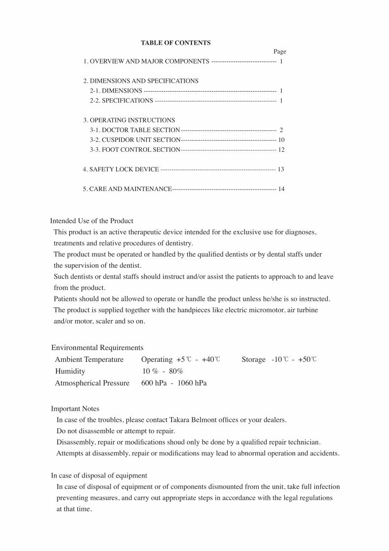
Page 1.OVERVIEWANDMAJORCOMPONENTS------------------------------ 1
2.DIMENSIONSANDSPECIFICATIONS 2-1.DIMENSIONS------------------------------------------------------------- 1 2-2.SPECIFICATIONS-------------------------------------------------------- 1
3.OPERATINGINSTRUCTIONS 3-1.DOCTORTABLESECTION-------------------------------------------- 2 3-2.CUSPIDORUNITSECTION-------------------------------------------- 10 3-3.FOOTCONTROLSECTION-------------------------------------------- 12
4.SAFETYLOCKDEVICE-----------------------------------------------------13
5.CAREANDMAINTENANCE------------------------------------------------ 14
TABLE OF CONTENTS
IntendedUseoftheProductThisproductisanactivetherapeuticdeviceintendedfortheexclusiveusefordiagnoses,treatmentsandrelativeproceduresofdentistry. The product must be operated or handled by the qualified dentists or by dental staffs under thesupervisionofthedentist.Suchdentistsordentalstaffsshouldinstructand/orassistthepatientstoapproachtoandleavefromtheproduct.Patientsshouldnotbeallowedtooperateorhandletheproductunlesshe/sheissoinstructed.Theproductissuppliedtogetherwiththehandpieceslikeelectricmicromotor,airturbineand/ormotor,scalerandsoon.
EnvironmentalRequirementsAmbientTemperatureOperating+5 -+40 Storage-10 -+50Humidity10%-80%AtmosphericalPressure600hPa-1060hPa
℃℃ ℃ ℃
ImportantNotes In case of the troubles, please contact Takara Belmont offices or your dealers. Donotdisassembleorattempttorepair. Disassembly, repair or modifications shoud only be done by a qualified repair technician. Attempts at disassembly, repair or modifications may lead to abnormal operation and accidents.
IncaseofdisposalofequipmentIncaseofdisposalofequipmentorofcomponentsdismountedfromtheunit,takefullinfectionpreventingmeasures,andcarryoutappropriatestepsinaccordancewiththelegalregulationsatthattime.
W A
MANUAL SENSOR
Chair last position Chair auto return Chair preset1 Chair preset2
To raise the chair To lower the chairTo Recline the backrest
To raise the backrest
Chair last position
Chair manual control Chair auto control
To lower the chair
Handpiece coolant spray on/off
Fiber optic handpiece lighton//off
Micro motor Forward/Reverseselect
Syringe Dental light on/off
Dental lightmode selection
Service outletwater flow control
Service outlet (water)
Service outlet (air)
Water heater
Air
Type B Applied Parts
CautionIt means “caution, warnings, or possibility to danger”.
Chair auto return Chair preset1
To Recline the backrest
To raise the backrest
Chair preset2
Chair manual control
Handpiece Setting
Rotation mode select
Minus Plus
Water
Function Store
Bowl flush Cupfiller
Rotation speedcontol
Protective earth (ground) ON (power) OFF (power)
Scalerpower control
alternating current
Refer to operating instructions
To raise the chair
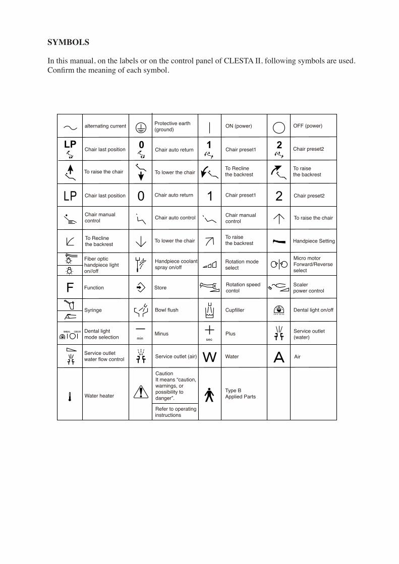
SYMBOLS
Inthismanual,onthelabelsoronthecontrolpanelofCLESTAII,followingsymbolsareused.Confirm the meaning of each symbol.
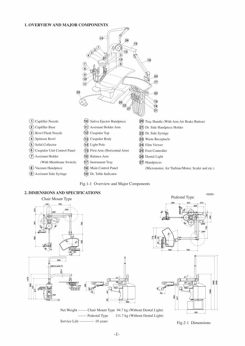
1. OVERVIEW AND MAJOR COMPONENTS
SalivaEjectorHandpiece
AssistantHolderArm
CuspidorTop
CuspidorBody
LightPole
FirstArm(HorizontalArm)
BalanceArm
InstrumentTray
MainControlPanel
Dr.TableIndicator
TrayHandle(WithArmAirBrakeButton)
Dr.SideHandpieceHolder
Dr.SideSyringe
WasteReceptacle
FilmViewer
FootController
DentalLight
Handpieces
(Micromotor,AirTurbine/Motor,Scalerandetc.)
Fig.1-1OverviewandMajorComponents
-1-
LP
21 0
F
W A
14
1526
16
24
17
191821
22
25 23
20
12
34
78
910
11
12
135
6W
A
27
Cupfiller Nozzle
Cupfiller Base
BowlFlushNozzle
SpittoonBowl
SolidCollector
CuspidorUnitControlPanel
AssistantHolder
(WithMembraneSwitch)
VacuumHandpiece
AssistantSideSyringe
2. DIMENSIONS AND SPECIFICATIONS -mm-
NetWeight-------ChairMountType94.7kg(WithoutDentalLight)-------PedestalType111.7kg(WithoutDentalLight)ServiceLife------------10years Fig.2-1Dimensions
9
13
1112
1516
10
8
14
7
2
6
1
43
5
18
22
2617
23
21
25
27
20
24
19
340
750
187
274651489
90°
90°
600
90°
340°
700592
57°87°
30°30°
688
718
55°
30°
21°
28°
1268
1898
1940
817894
661
290°
298
290˚340˚
700
30˚ 30˚718
592
30˚
21˚
28˚
57˚87˚
890
1479
274
90˚
517
90˚
90˚
138˚
55˚ 441
184
569
60
60.5
651
489
737
ø50.8 (ø42.7)
600
750187
ChairMountType PedestalType
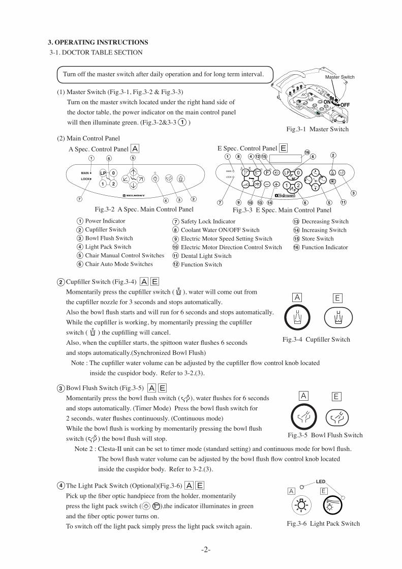
Fig.3-1MasterSwitch
ON OFF
Master Switch
Fig.3-4 Cupfiller Switch
Turnoffthemasterswitchafterdailyoperationandforlongterminterval.
3. OPERATING INSTRUCTIONS3-1.DOCTORTABLESECTION
(1)MasterSwitch(Fig.3-1,Fig.3-2&Fig.3-3)Turnonthemasterswitchlocatedundertherighthandsideofthedoctortable,thepowerindicatoronthemaincontrolpanelwillthenilluminategreen.(Fig.3-2&3-3)
LOCK
3 2
MAIN
1
47
56
LP
21
0
(2)MainControlPanelASpec.ControlPanel
Cupfiller Switch (Fig.3-4) Momentarily press the cupfiller switch ( ), water will come out fromthe cupfiller nozzle for 3 seconds and stops automatically. Also the bowl flush starts and will run for 6 seconds and stops automatically.While the cupfiller is working, by momentarily pressing the cupfiller switch ( ) the cupfilling will cancel.Also, when the cupfiller starts, the spittoon water flushes 6 secondsandstopsautomatically.(SynchronizedBowlFlush) Note : The cupfiller water volume can be adjusted by the cupfiller flow control knob located insidethecuspidorbody.Referto3-2.(3).
A E
1
1
7
3
48 12 15 6 2
9 1310 14 6
16
5 11
Fig.3-3ESpec.MainControlPanel
72
6
1
4
3
5
13
11
12
15
1610
14
9
8
PowerIndicatorCupfiller SwitchBowlFlushSwitchLightPackSwitchChairManualControlSwitchesChairAutoModeSwitches
DecreasingSwitchIncreasingSwitchStoreSwitchFunctionIndicator
Fig.3-2ASpec.MainControlPanel
BowlFlushSwitch(Fig.3-5)Momentarily press the bowl flush switch ( ), water flushes for 6 secondsand stops automatically. (Timer Mode) Press the bowl flush switch for 2 seconds, water flushes continuously. (Continuous mode)While the bowl flush is working by momentarily pressing the bowl flush switch ( ) the bowl flush will stop. Note 2 : Clesta-II unit can be set to timer mode (standard setting) and continuous mode for bowl flush. The bowl flush water volume can be adjusted by the bowl flush flow control knob located insidethecuspidorbody.Referto3-2.(3).
Fig.3-5BowlFlushSwitch
A E
SafetyLockIndicatorCoolantWaterON/OFFSwitchElectricMotorSpeedSettingSwitchElectricMotorDirectionControlSwitchDentalLightSwitchFunctionSwitch
Fig.3-6LightPackSwitch
LED
A ETheLightPackSwitch(Optional)(Fig.3-6)Pick up the fiber optic handpiece from the holder, momentarily pressthelightpackswitch(),theindicatorilluminatesingreenand the fiber optic power turns on. Toswitchoffthelightpacksimplypressthelightpackswitchagain.
ESpec.ControlPanel
2
3
4
EA
EA
EA
-2-
EA EA
-3-
Fig.3-7ChairManualControlSwitches
A E
Fig.3-8ChairAutoModeSwitches
LP
21
0
A E
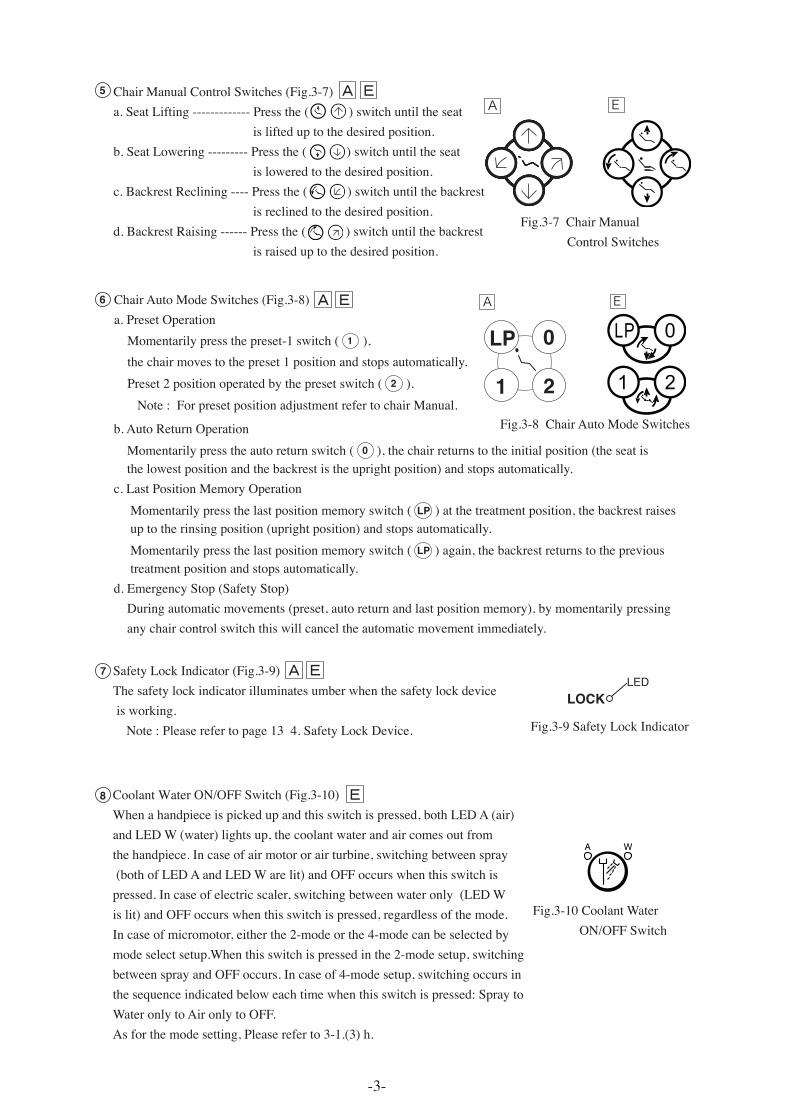
ChairManualControlSwitches(Fig.3-7)a.SeatLifting-------------Pressthe()switchuntiltheseatislifteduptothedesiredposition.b.SeatLowering---------Pressthe()switchuntiltheseatisloweredtothedesiredposition.c.BackrestReclining----Pressthe()switchuntilthebackrestisreclinedtothedesiredposition.d.BackrestRaising------Pressthe()switchuntilthebackrestisraiseduptothedesiredposition.
b.AutoReturnOperationMomentarilypresstheautoreturnswitch( 0 ),thechairreturnstotheinitialposition(theseatisthelowestpositionandthebackrestistheuprightposition)andstopsautomatically.c.LastPositionMemoryOperationMomentarilypressthelastpositionmemoryswitch( LP )atthetreatmentposition,thebackrestraisesuptotherinsingposition(uprightposition)andstopsautomatically.Momentarilypressthelastpositionmemoryswitch( LP )again,thebackrestreturnstotheprevioustreatmentpositionandstopsautomatically.d.EmergencyStop(SafetyStop)Duringautomaticmovements(preset,autoreturnandlastpositionmemory),bymomentarilypressinganychaircontrolswitchthiswillcanceltheautomaticmovementimmediately.
SafetyLockIndicator(Fig.3-9)Thesafetylockindicatorilluminatesumberwhenthesafetylockdeviceisworking.Note:Pleaserefertopage134.SafetyLockDevice.
CoolantWaterON/OFFSwitch(Fig.3-10)Whenahandpieceispickedupandthisswitchispressed,bothLEDA(air)andLEDW(water)lightsup,thecoolantwaterandaircomesoutfromthehandpiece.Incaseofairmotororairturbine,switchingbetweenspray(bothofLEDAandLEDWarelit)andOFFoccurswhenthisswitchispressed.Incaseofelectricscaler,switchingbetweenwateronly(LEDWislit)andOFFoccurswhenthisswitchispressed,regardlessofthemode.Incaseofmicromotor,eitherthe2-modeorthe4-modecanbeselectedbymodeselectsetup.Whenthisswitchispressedinthe2-modesetup,switchingbetweensprayandOFFoccurs.Incaseof4-modesetup,switchingoccursinthesequenceindicatedbeloweachtimewhenthisswitchispressed:SpraytoWateronlytoAironlytoOFF.Asforthemodesetting,Pleasereferto3-1.(3)h.
Fig.3-10CoolantWaterON/OFFSwitch
ChairAutoModeSwitches(Fig.3-8)a.PresetOperationMomentarilypressthepreset-1switch( 1 ),thechairmovestothepreset1positionandstopsautomatically.Preset2positionoperatedbythepresetswitch( 2 ).Note:ForpresetpositionadjustmentrefertochairManual.
8
7
6
5 EA
EA
EA
EA
Fig.3-9SafetyLockIndicator
LOCKLED
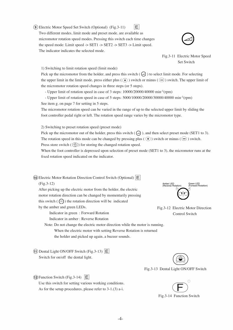
Fig.3-8ChairAutoModeSwitches
Fig.3-11ElectricMotorSpeedSetSwitch
1)Switchingtolimitrotationspeed(limitmode)Pickupthemicromotorfromtheholder,andpressthisswitch()toselectlimitmode.Forselectingtheupperlimitinthelimitmode,presseitherplus()switchorminus()switch.Theupperlimitofthemicromotorrotationspeedchangesinthreesteps(or5steps).-Upperlimitofrotationspeedincaseof3steps:10000/20000/40000min-1(rpm)-Upperlimitofrotationspeedincaseof5steps:5000/10000/20000/30000/40000min-1(rpm)Seeitemg.onpage7forsettingin5steps.Themicromotorrotationspeedcanbevariedintherangeofuptotheselectedupperlimitbyslidingthefootcontrollerpedalrightorleft.Therotationspeedrangevariesbythemicromotortype.
2)Switchingtopresetrotationspeed(presetmode)Pickupthemicromotoroutoftheholder,pressthisswitch(),andthenselectpresetmode(SET1to3).Therotationspeedinthismodecanbechangedbypressingplus()switchorminus()switch.Pressstoreswitch()forstoringthechangedrotationspeed.Whenthefootcontrollerisdepresseduponselectionofpresetmode(SET1to3),themicromotorrunsatthefixed rotation speed indicated on the indicator.
-4-
ElectricMotorSpeedSetSwitch(Optional)(Fig.3-11)Twodifferentmodes,limitmodeandpresetmode,areavailableasmicromotorrotationspeedmodes.Pressingthisswitcheachtimechangesthespeedmode:Limitspeed->SET1->SET2->SET3->Limitspeed.Theindicatorindicatestheselectedmode.
Green LED(Forward Rotaition)
Amber LED(Reverse Rotation)
ElectricMotorRotationDirectionControlSwitch(Optional)(Fig.3-12)Afterpickinguptheelectricmotorfromtheholder,theelectricmotorrotationdirectioncanbechangedbymomentarilypressingthisswitch()therotationdirectionwillbeindicatedbytheamberandgreenLEDs.Indicatoringreen:ForwardRotationIndicatorinamber:ReverseRotationNote:Donotchangetheelectricmotordirectionwhilethemotorisrunning.WhentheelectricmotorwithsettingReverseRotationisreturnedtheholderandpickedupagain,abuzzersounds.
Fig.3-12ElectricMotorDirectionControlSwitch
DentalLightON/OFFSwitch(Fig.3-13)Switchforon/offthedentallight.
FunctionSwitch(Fig.3-14)Usethisswitchforsettingvariousworkingconditions.Asforthesetupprocedures,pleasereferto3-1.(3)a-i.
9
11
12
10
EA
EA
EA
EA
Fig.3-13DentalLightON/OFFSwitch
Fig.3-14FunctionSwitch
+
+
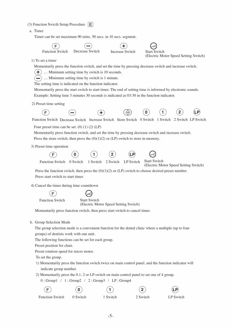
(3)FunctionSwicthSetupProcedure
b.GroupSelectionModeThegroupselectionmodeisaconvenientfunctionforthedentalclinicwhereamultiple(uptofourgroups)ofdentistsworkwithoneunit.Thefollowingfunctionscanbesetforeachgroup.Presetpositionforchair.Presetrotationspeedformicromotor.Tosetthegroup.1)Momentarilypressthefunctionswitchtwiceonmaincontrolpanel,andthefunctionindicatorwillindicategroupnumber.2)Momentarilypressthe0,1,2orLPswitchonmaincontrolpaneltosetoneof4group.0;Group1/1;Group2/2;Group3/LP;Group4
FunctionSwitch 0Switch 1Switch 2Switch LPSwitch
1)TosetatimerMomentarilypressthefunctionswitch,andsetthetimebypressingdecreaseswitchandincreaseswitch. …Minimumsettingtimebyswitchis10seconds. …Minimumsettingtimebyswitchis1minute.Thesettingtimeisindicatedonthefunctionindicator.Momentarilypressthestartswitchtostarttimer.Theendofsettingtimeisinformedbyelectronicsounds.Example:Settingtime3minutes30secondsisindicatedas03:30inthefunctionindicator.
a.TimerTimercanbesetmaximum90mins.50secs.in10secs.segment.
FunctionSwitch DecreaseSwitch IncreaseSwitch
-5-
+
0 1 2 LP
StartSwitch(ElectricMotorSpeedSettingSwitch)
+
Fourpresettimecanbeset.(0)(1)(2)(LP)Momentarilypressfunctionswitch,andsetthetimebypressingdecreaseswitchandincreaseswitch.Pressthestoreswitch,thenpressthe(0)(1)(2)or(LP)switchtostoreinmemory.
0Switch 1Switch 2Switch LPSwitch
0 1 2 LP
2)Presettimesetting
StoreSwitchFunctionSwitch DecreaseSwitch IncreaseSwitch
+
3)Presettimeoperation
4)Cancelthetimerduringtimecountdown
0Switch 1Switch 2Switch LPSwitch
0 1 2 LPFunctionSwitch StartSwitch
(ElectricMotorSpeedSettingSwitch)Pressthefunctionswitch,thenpressthe(0)(1)(2)or(LP)switchtochoosedesiredpresetnumber.Pressstartswitchtostarttimer.
Momentarilypressfunctionswitch,thenpressstartswitchtocanceltimer.
FunctionSwitch StartSwitch(ElectricMotorSpeedSettingSwitch)
EA
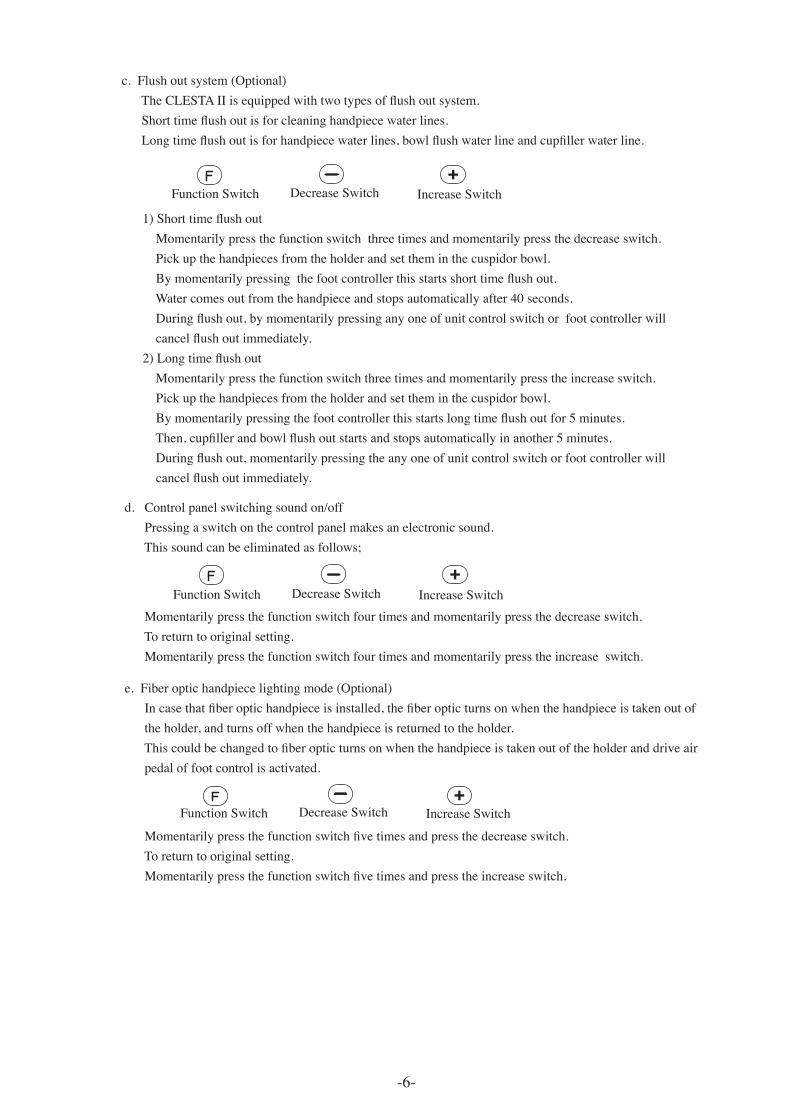
1) Short time flush outMomentarilypressthefunctionswitchthreetimesandmomentarilypressthedecreaseswitch.Pickupthehandpiecesfromtheholderandsettheminthecuspidorbowl. By momentarily pressing the foot controller this starts short time flush out.Watercomesoutfromthehandpieceandstopsautomaticallyafter40seconds. During flush out, by momentarily pressing any one of unit control switch or foot controller will cancel flush out immediately. 2) Long time flush outMomentarilypressthefunctionswitchthreetimesandmomentarilypresstheincreaseswitch.Pickupthehandpiecesfromtheholderandsettheminthecuspidorbowl. By momentarily pressing the foot controller this starts long time flush out for 5 minutes. Then, cupfiller and bowl flush out starts and stops automatically in another 5 minutes. During flush out, momentarily pressing the any one of unit control switch or foot controller will cancel flush out immediately.
c.Flushoutsystem(Optional) The CLESTA II is equipped with two types of flush out system. Short time flush out is for cleaning handpiece water lines. Long time flush out is for handpiece water lines, bowl flush water line and cupfiller water line.
FunctionSwitch DecreaseSwitch IncreaseSwitch+
e.Fiberoptichandpiecelightingmode(Optional) In case that fiber optic handpiece is installed, the fiber optic turns on when the handpiece is taken out of theholder,andturnsoffwhenthehandpieceisreturnedtotheholder. This could be changed to fiber optic turns on when the handpiece is taken out of the holder and drive air pedaloffootcontrolisactivated.
Momentarily press the function switch five times and press the decrease switch.Toreturntooriginalsetting. Momentarily press the function switch five times and press the increase switch.
FunctionSwitch DecreaseSwitch IncreaseSwitch
d.Controlpanelswitchingsoundon/offPressingaswitchonthecontrolpanelmakesanelectronicsound.Thissoundcanbeeliminatedasfollows;
Momentarilypressthefunctionswitchfourtimesandmomentarilypressthedecreaseswitch.Toreturntooriginalsetting.Momentarilypressthefunctionswitchfourtimesandmomentarilypresstheincreaseswitch.
FunctionSwitch DecreaseSwitch IncreaseSwitch+
+
-6-
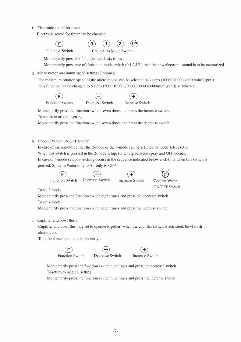
g.Micromotormaximumspeedsetting(Optional)
Themaximumrotationspeedofthemicromotorcanbeselectedin3steps(10000,20000,40000min-1(rpm)).Thisfunctioncanbechangedto5steps(5000,10000,20000,30000,40000min-1(rpm))asfollows:
Momentarilypressthefunctionswitchseventimesandpresstheincreaseswitch.Toreturntooriginalsetting.Momentarilypressthefunctionswitchseventimesandpressthedecreaseswitch.
FunctionSwitch DecreaseSwitch IncreaseSwitch+
-7-
Momentarilypressthefunctionswitchsixtimes. Momentarilypressoneofchairautomodeswitch(0,1,2,LP)thenthenewelectronicsoundistobememorized.
f.ElectronicsoundfortimerElectronicsoundfortimercanbechanged.
FunctionSwitch ChairAutoModeSwitch
0 2 LP1
h.CoolantWaterON/OFFSwitchIncaseofmicromotor,eitherthe2-modeorthe4-modecanbeselectedbymodeselectsetup.Whenthisswitchispressedinthe2-modesetup,switchingbetweensprayandOFFoccurs.Incaseof4-modesetup,switchingoccursinthesequenceindicatedbeloweachtimewhenthisswitchispressed:SpraytoWateronlytoAironlytoOFF.
Toset2modeMomentarilypressthefunctionswitcheighttimesandpressthedecreaseswitch.Toset4modeMomentarilypressthefunctionswitcheighttimesandpresstheincreaseswitch.
+FunctionSwitch DecreaseSwitch IncreaseSwitch CoolantWater
ON/OFFSwitch
i. Cupfiller and bowl flush Cupfiller and bowl flush are set to operate together (when the cupfiller switch is activated, bowl flushalsostarts).Tomaketheseoperateindependently.
Momentarilypressthefunctionswitchninetimesandpressthedecreaseswitch.Toreturntooriginalsetting.Momentarilypressthefunctionswitchninetimesandpresstheincreaseswitch.
FunctionSwitch DecreaseSwitch IncreaseSwitch+
Momentarilypressthefunctionswitchsixtimes. Momentarilypressoneofchairautomodeswitch(0,1,2,LP)thenthenewelectronicsoundistobememorized.
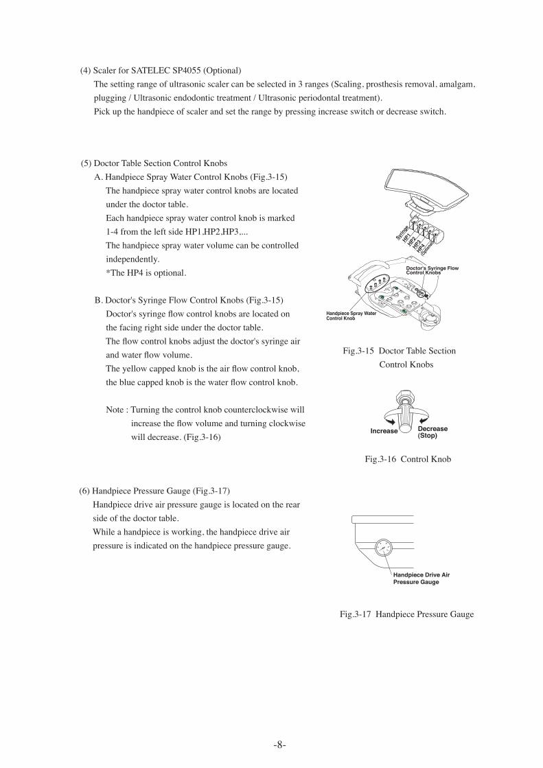
(5)DoctorTableSectionControlKnobsA.HandpieceSprayWaterControlKnobs(Fig.3-15)Thehandpiecespraywatercontrolknobsarelocatedunderthedoctortable.Eachhandpiecespraywatercontrolknobismarked1-4fromtheleftsideHP1,HP2,HP3,...Thehandpiecespraywatervolumecanbecontrolledindependently.*TheHP4isoptional.
B.Doctor'sSyringeFlowControlKnobs(Fig.3-15) Doctor's syringe flow control knobs are located onthefacingrightsideunderthedoctortable. The flow control knobs adjust the doctor's syringe air and water flow volume. The yellow capped knob is the air flow control knob, the blue capped knob is the water flow control knob.
Note:Turningthecontrolknobcounterclockwisewill increase the flow volume and turning clockwisewilldecrease.(Fig.3-16)
(4)ScalerforSATELECSP4055(Optional)Thesettingrangeofultrasonicscalercanbeselectedin3ranges(Scaling,prosthesisremoval,amalgam,plugging/Ultrasonicendodontictreatment/Ultrasonicperiodontaltreatment).Pickupthehandpieceofscalerandsettherangebypressingincreaseswitchordecreaseswitch.
Fig.3-15DoctorTableSectionControlKnobs
Fig.3-16ControlKnob
Increase Decrease(Stop)
Doctor's Syringe Flow Control Knobs
Handpiece Spray Water Control Knob
HP1HP2
HP3HP4
(Opti
onal)
Syring
e
-8-
(6)HandpiecePressureGauge(Fig.3-17)Handpiecedriveairpressuregaugeislocatedontherearsideofthedoctortable.Whileahandpieceisworking,thehandpiecedriveairpressureisindicatedonthehandpiecepressuregauge. 1
2 3
4
5
Handpiece Drive Air Pressure Gauge
Fig.3-17HandpiecePressureGauge
-9-
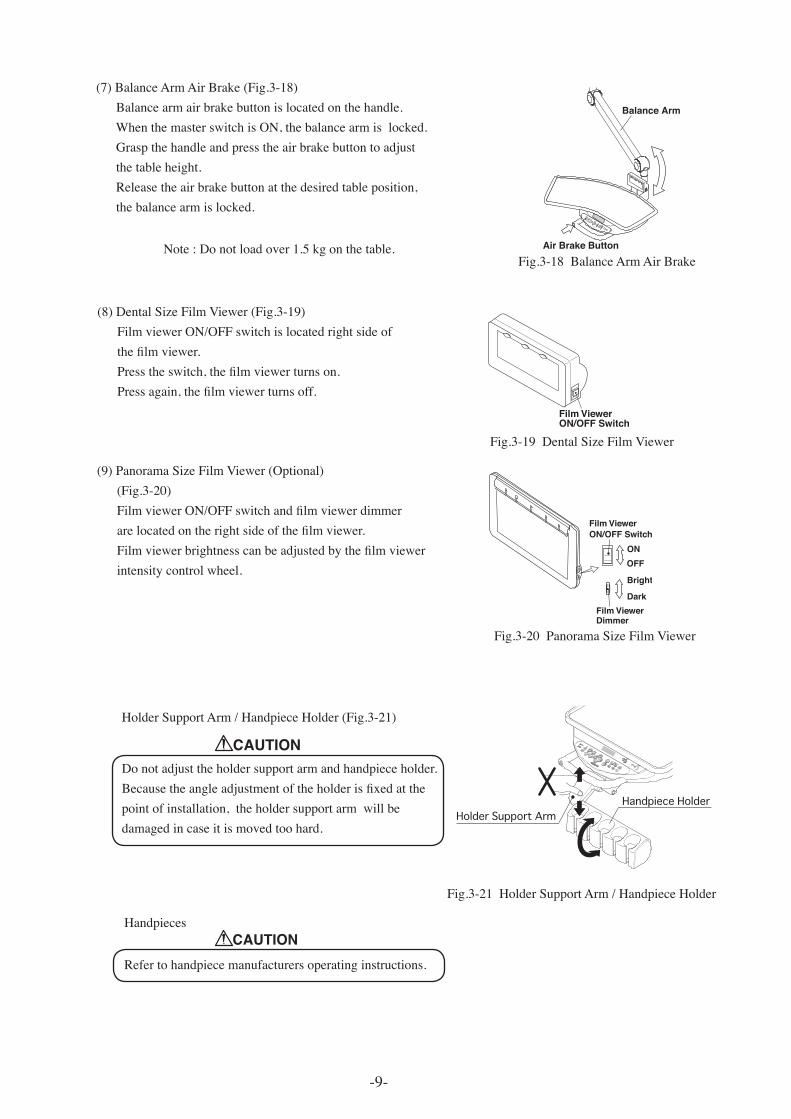
(7)BalanceArmAirBrake(Fig.3-18)Balancearmairbrakebuttonislocatedonthehandle.WhenthemasterswitchisON,thebalancearmislocked.Graspthehandleandpresstheairbrakebuttontoadjustthetableheight.Releasetheairbrakebuttonatthedesiredtableposition,thebalancearmislocked.
Fig.3-18BalanceArmAirBrake
LP
21 0
F
Air Brake Button
Balance Arm
Note:Donotloadover1.5kgonthetable.
(8)DentalSizeFilmViewer(Fig.3-19)FilmviewerON/OFFswitchislocatedrightsideof the film viewer. Press the switch, the film viewer turns on. Press again, the film viewer turns off.
Film ViewerON/OFF Switch
Fig.3-19DentalSizeFilmViewer
Fig.3-20PanoramaSizeFilmViewer
Film ViewerON/OFF Switch
Film Viewer Dimmer
ONOFF
Bright
Dark
HolderSupportArm/HandpieceHolder(Fig.3-21)
Donotadjusttheholdersupportarmandhandpieceholder. Because the angle adjustment of the holder is fixed at thepointofinstallation,theholdersupportarmwillbedamagedincaseitismovedtoohard.
CAUTION
Handpieces
Refertohandpiecemanufacturersoperatinginstructions.
CAUTION
(9)PanoramaSizeFilmViewer(Optional)(Fig.3-20) Film viewer ON/OFF switch and film viewer dimmer are located on the right side of the film viewer. Film viewer brightness can be adjusted by the film viewerintensitycontrolwheel.
Fig.3-21HolderSupportArm/HandpieceHolder
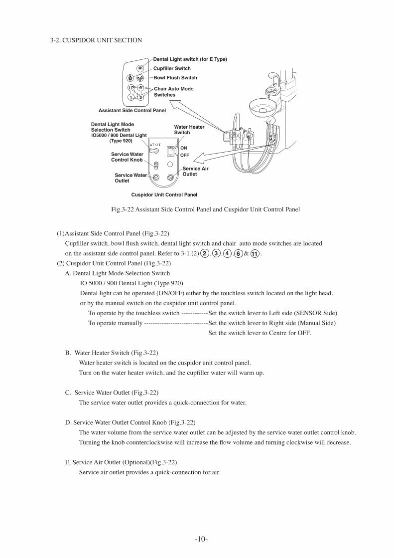
Fig.3-22AssistantSideControlPanelandCuspidorUnitControlPanel
-10-
(1)AssistantSideControlPanel(Fig.3-22) Cupfiller switch, bowl flush switch, dental light switch and chair auto mode switches are located ontheassistantsidecontrolpanel.Referto3-1.(2),,,&.(2)CuspidorUnitControlPanel(Fig.3-22)A.DentalLightModeSelectionSwitchIO5000/900DentalLight(Type920)Dentallightcanbeoperated(ON/OFF)eitherbythetouchlessswitchlocatedonthelighthead,orbythemanualswitchonthecuspidorunitcontrolpanel.Tooperatebythetouchlessswitch------------SettheswitchlevertoLeftside(SENSORSide)Tooperatemanually-----------------------------SettheswitchlevertoRightside(ManualSide) SettheswitchlevertoCentreforOFF.
B.WaterHeaterSwitch(Fig.3-22) Waterheaterswitchislocatedonthecuspidorunitcontrolpanel. Turn on the water heater switch, and the cupfiller water will warm up.
C.ServiceWaterOutlet(Fig.3-22) Theservicewateroutletprovidesaquick-connectionforwater.
D.ServiceWaterOutletControlKnob(Fig.3-22) Thewatervolumefromtheservicewateroutletcanbeadjustedbytheservicewateroutletcontrolknob. Turning the knob counterclockwise will increase the flow volume and turning clockwise will decrease.E.ServiceAirOutlet(Optional)(Fig,3-22) Serviceairoutletprovidesaquick-connectionforair.
3-2.CUSPIDORUNITSECTION
Water HeaterSwitch
Service WaterOutlet
Service WaterControl Knob
Service AirOutlet
Cupfiller Switch
Dental Light switch (for E Type)
Chair Auto ModeSwitches
Bowl Flush Switch
Assistant Side Control Panel
Cuspidor Unit Control Panel
ONOFF
W A
LP
21
0
IO5000 / 900 Dental Light (Type 920)
Dental Light ModeSelection Switch
6 11432
-11-
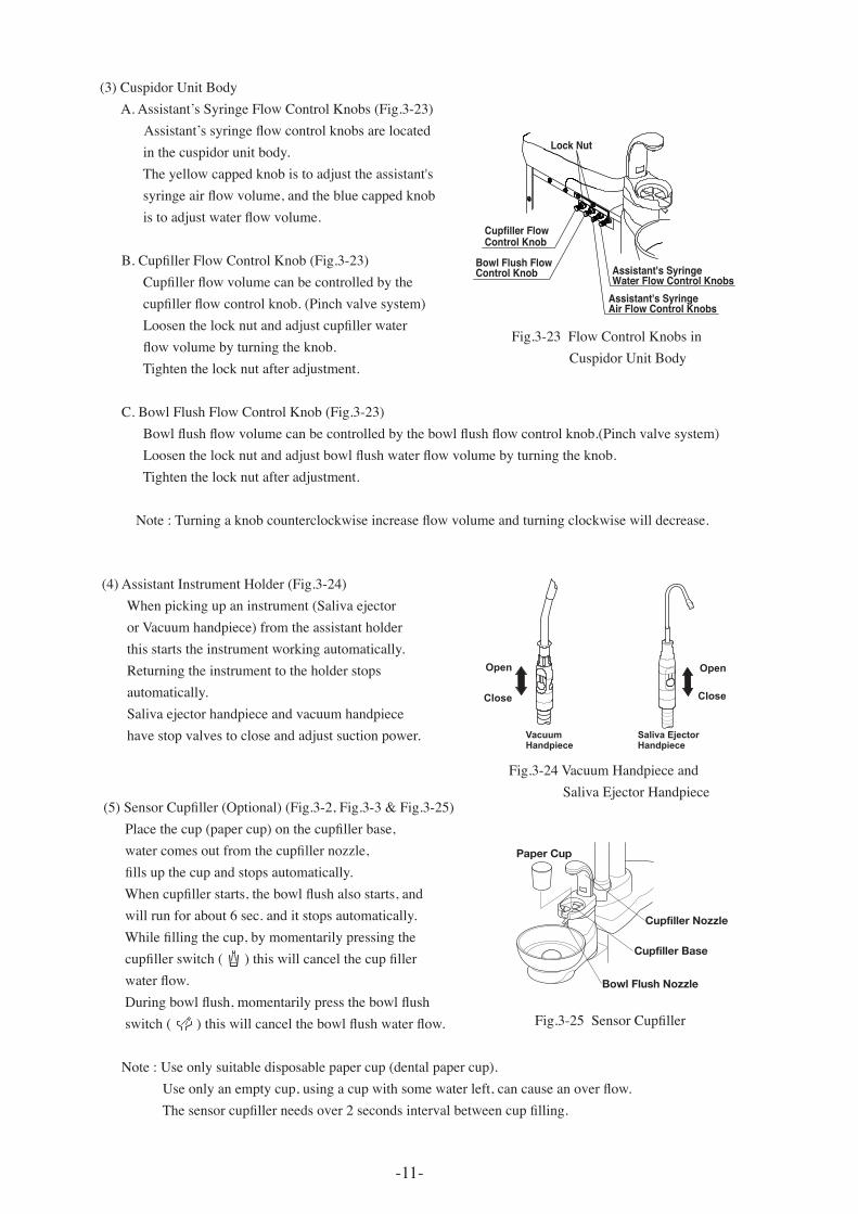
(3)CuspidorUnitBodyA.Assistant’sSyringeFlowControlKnobs(Fig.3-23) Assistant’s syringe flow control knobs are locatedinthecuspidorunitbody.Theyellowcappedknobistoadjusttheassistant's syringe air flow volume, and the blue capped knob is to adjust water flow volume.
B. Cupfiller Flow Control Knob (Fig.3-23) Cupfiller flow volume can be controlled by the cupfiller flow control knob. (Pinch valve system) Loosen the lock nut and adjust cupfiller water flow volume by turning the knob.Tightenthelocknutafteradjustment.
C.BowlFlushFlowControlKnob(Fig.3-23) Bowl flush flow volume can be controlled by the bowl flush flow control knob.(Pinch valve system) Loosen the lock nut and adjust bowl flush water flow volume by turning the knob.Tightenthelocknutafteradjustment.
Note : Turning a knob counterclockwise increase flow volume and turning clockwise will decrease.
Fig.3-23FlowControlKnobsinCuspidorUnitBody
(5) Sensor Cupfiller (Optional) (Fig.3-2, Fig.3-3 & Fig.3-25) Place the cup (paper cup) on the cupfiller base, water comes out from the cupfiller nozzle, fills up the cup and stops automatically. When cupfiller starts, the bowl flush also starts, andwillrunforabout6sec.anditstopsautomatically. While filling the cup, by momentarily pressing the cupfiller switch ( ) this will cancel the cup filler water flow. During bowl flush, momentarily press the bowl flush switch ( ) this will cancel the bowl flush water flow.
Note:Useonlysuitabledisposablepapercup(dentalpapercup). Use only an empty cup, using a cup with some water left, can cause an over flow. The sensor cupfiller needs over 2 seconds interval between cup filling.
Fig.3-25 Sensor Cupfiller
Cupfiller Nozzle
Bowl Flush Nozzle
Cupfiller Base
Paper Cup
(4)AssistantInstrumentHolder(Fig.3-24)Whenpickingupaninstrument(SalivaejectororVacuumhandpiece)fromtheassistantholderthisstartstheinstrumentworkingautomatically.Returningtheinstrumenttotheholderstopsautomatically.Salivaejectorhandpieceandvacuumhandpiecehavestopvalvestocloseandadjustsuctionpower.
Fig.3-19 VacuumHandpieceandSalivaEjectorHandpiece
Vacuum Handpiece
Saliva EjectorHandpiece
Open
Close
Open
Close
Assistant's SyringeWater Flow Control Knobs
Assistant's SyringeAir Flow Control Knobs
Lock Nut
Bowl Flush FlowControl Knob
Cupfiller Flow Control Knob
Fig.3-24VacuumHandpieceandSalivaEjectorHandpiece
-12-
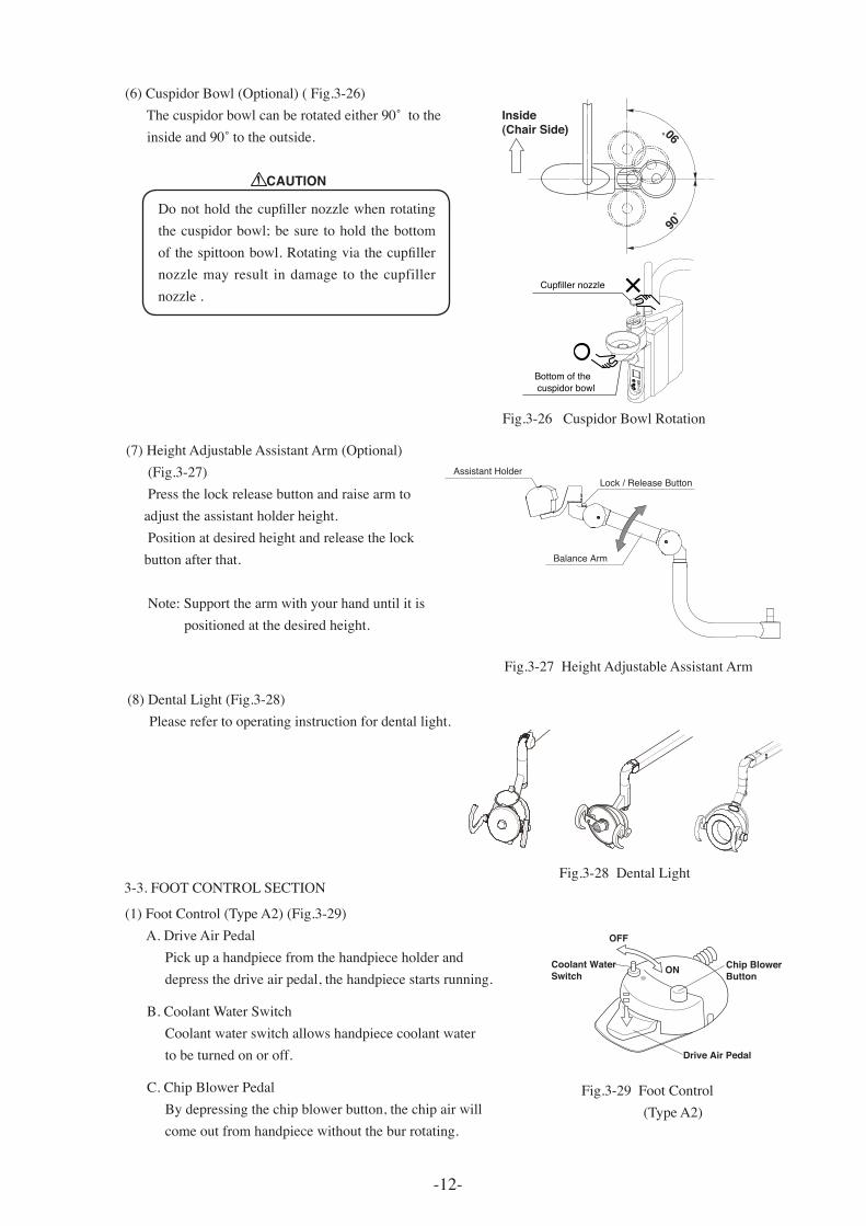
(1)FootControl(TypeA2)(Fig.3-29)A.DriveAirPedalPickupahandpiecefromthehandpieceholderanddepressthedriveairpedal,thehandpiecestartsrunning. B.CoolantWaterSwitchCoolantwaterswitchallowshandpiececoolantwatertobeturnedonoroff.
C.ChipBlowerPedalBydepressingthechipblowerbutton,thechipairwillcomeoutfromhandpiecewithouttheburrotating.
Fig.3-29FootControl(TypeA2)
3-3.FOOTCONTROLSECTION
(6)CuspidorBowl(Optional)(Fig.3-26) The cuspidor bowl can be rotated either 90˚ to the inside and 90˚ to the outside.
Coolant WaterSwitch
Drive Air Pedal
OFF
ON Chip Blower Button
Fig.3-26CuspidorBowlRotation
90˚�
90˚�
Inside�(Chair Side)
Assistant HolderLock / Release Button
Balance Arm
(7)HeightAdjustableAssistantArm(Optional)(Fig.3-27)Pressthelockreleasebuttonandraisearmtoadjusttheassistantholderheight.Positionatdesiredheightandreleasethelockbuttonafterthat.Note:Supportthearmwithyourhanduntilitispositionedatthedesiredheight.
Fig.3-27HeightAdjustableAssistantArm
Cupfiller nozzle
Bottom of the cuspidor bowl
CAUTION
Do not hold the cupfiller nozzle when rotating thecuspidorbowl;besuretoholdthebottomof the spittoon bowl. Rotating via the cupfiller nozzlemayresult indamage to thecupfillernozzle.
Fig.3-28DentalLight
(8)DentalLight(Fig.3-28)Pleaserefertooperatinginstructionfordentallight.
Coolant WaterSwitch
Drive Air Pedal
Chip Blower Button
Increase Electric MotorRotation Speed
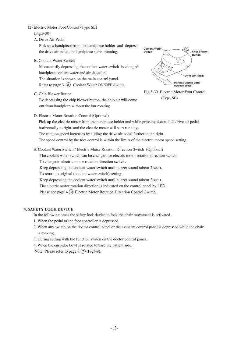
(2)ElectricMotorFootControl(TypeSE)(Fig.3-30)A.DriveAirPedalPickupahandpiecefromthehandpieceholderanddepressthedriveairpedal,thehandpiecestartsrunning. B.CoolantWaterSwitchMomentarilydepressingthecoolantwaterswitchischangedhandpiececoolantwaterandairsituation.Thesituationisshownonthemaincontrolpanel.Refertopage3CoolantWaterON/OFFSwitch.
C.ChipBlowerButtonBydepressingthechipblowerbutton,thechipairwillcomeoutfromhandpiecewithouttheburrotating.
E.CoolantWaterSwitch/ElectricMotorRotationDirectionSwitch(Optional)Thecoolantwaterswitchcanbechangedforelectricmotorrotationdirectionswitch.Tochangetoelectricmotorrotationdirectionswitch.Keepdepressingthecoolantwaterswitchuntilbuzzersound(about2sec.).Toreturntooriginal(coolantwaterswitch)setting.Keepdepressingthecoolantwaterswitchuntilbuzzersound(about2sec.).TheelectricmotorrotationdirectionisindicatedonthecontrolpanelbyLED.Pleaseseepage4ElectricMotorRotationDirectionControlSwitch.
D.ElectricMotorRotationControl(Optional)Pickuptheelectricmotorfromthehandpieceholderandwhilepressingdownslidedriveairpedalhorizontallytoright,andtheelectricmotorwillstartrunning.Therotationspeedincreasesbyslidingthedriveairpedalfurthertotheright.Thespeedcontrolbythefootcontroliswithinthelimitsoftheelectricmotorspeedsetting.
Fig.3-30ElectricMotorFootControl(TypeSE)
Inthefollowingcasesthesafetylockdevicetolockthechairmovementisactivated.1.Whenthepedalofthefootcontrollerisdepressed.2.Whenanyswitchonthedoctorcontrolpanelortheassistantcontrolpanelisdepressedwhilethechairismoving.3.Duringsettingwiththefunctionswitchonthedoctorcontrolpanel.4.Whenthecuspidorbowlisrotatedtowardthepatientside.Note:Pleaserefertopage3(Fig3-9).
-13-
10
4. SAFETY LOCK DEVICE
7
8
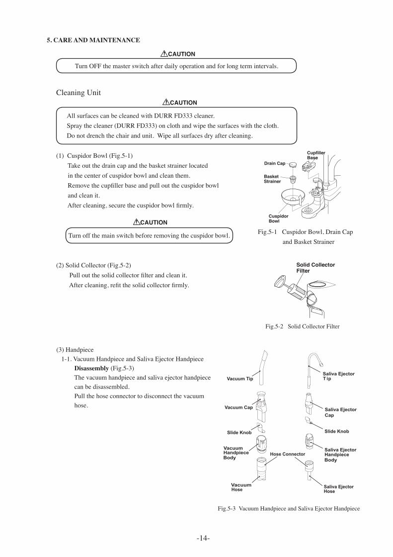
Fig.5-1CuspidorBowl,DrainCapandBasketStrainer
Fig.5-2SolidCollectorFilter
Drain Cap
BasketStrainer
Cuspidor Bowl
CupfillerBase
Solid CollectorFilter
5. CARE AND MAINTENANCE
TurnOFFthemasterswitchafterdailyoperationandforlongtermintervals.
CleaningUnit
(1)CuspidorBowl(Fig.5-1)Takeoutthedraincapandthebasketstrainerlocatedinthecenterofcuspidorbowlandcleanthem. Remove the cupfiller base and pull out the cuspidor bowl andcleanit. After cleaning, secure the cuspidor bowl firmly.
Turnoffthemainswitchbeforeremovingthecuspidorbowl.
(2)SolidCollector(Fig.5-2) Pull out the solid collector filter and clean it. After cleaning, refit the solid collector firmly.
-14-
AllsurfacescanbecleanedwithDURRFD333cleaner.Spraythecleaner(DURRFD333)onclothandwipethesurfaceswiththecloth.Donotdrenchthechairandunit.Wipeallsurfacesdryaftercleaning.
CAUTION
CAUTION
CAUTION
(3)Handpiece1-1.VacuumHandpieceandSalivaEjectorHandpieceDisassembly(Fig.5-3)Thevacuumhandpieceandsalivaejectorhandpiececanbedisassembled.Pullthehoseconnectortodisconnectthevacuumhose.
Vacuum Tip
Saliva EjectorHandpiece
VacuumHandpiece
Vacuum
Vacuum Cap
Saliva EjectorT ip
Saliva EjectorHose
Body Body
Hose
Slide Knob Slide Knob
Saliva EjectorCap
Hose Connector
Fig.5-3 VacuumHandpieceandSalivaEjectorHandpiece
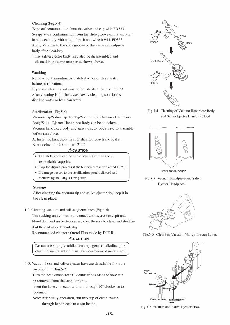
Sterilization(Fig.5-5)VacuumTip/SalivaEjectorTip/VacuumCap/VacuumHandpieceBody/SalivaEjectorHandpieceBodycanbeautoclave.Vacuumhandpiecebodyandsalivaejectorbodyhavetoassemblebeforeautoclave.A.Insertthehandpieceinasterilizationpouchandsealit. B. Autoclave for 20 min. at 121℃ •Theslideknobcanbeautoclave100timesandisexpendablesupplies.•Skip the drying process if the temperature is to exceed 135℃.•Ifdamageoccurstothesterilizationpouch,discardandsterilizeagainusinganewpouch.
StorageAftercleaningthevacuumtipandsalivaejectortip,keepitinthecleanplace.
Cleaning(Fig.5-4)WipeoffcontaminationfromthevalveandcapwithFD333.ScrapeawaycontaminationfromtheslidegrooveofthevacuumhandpiecebodywithatoothbrushandwipeitwithFD333.ApplyVaselinetotheslidegrooveofthevacuumhandpiecebodyaftercleaning.*Thesalivaejectorbodymayalsobedisassembledandcleanedinthesamemannerasshownabove. Washing Removecontaminationbydistilledwaterorcleanwaterbeforesterilization.Ifyouusecleaningsolutionbeforesterilization,useFD333. After cleaning is finished, wash away cleaning solution by distilledwaterorbycleanwater.
Cap
Valve
Body
Tooth Brush
FD333
FD333
Sterilization pouch
1-2.Cleaningvacuumandsalivaejectorlines(Fig.5-6)Thesuckingunitcomesintocontactwithsecretions,spitandbloodthatcontainbacteriaeveryday.Besuretocleanandsterilizeitattheendofeachworkday.Recommendedcleaner:OrotolPlusmadebyDURR.
1-3.Vacuumhoseandsalivaejectorhosearedetachablefromthecuspidorunit.(Fig.5-7) Turn the hose connector 90˚ counterclockwise the hose can beremovedfromthecuspidorunit. Insert the hose connector and turn through 90˚ clockwise to reconnect.Note:Afterdailyoperation,runtwocupofcleanwaterthroughhandpiecestocleaninside.
Fig.4-4 VacuumandSalivaEjectorHose
Vacuum Hose Saliva EjectorHose
HoseConnector
Fix
FixRelease
Release
W A
Fig.5-7VacuumandSalivaEjectorHose
CAUTION
Donotusestronglyacidiccleaningagentsoralkalinepipecleaningagents,whichmaycausecorrosionofmetals,etc/
Fig.5-4CleaningofVacuumHandpieceBodyandSalivaEjectorHandpieceBody
Fig.5-5VacuumHandpieceandSalivaEjectorHandpiece
Fig.5-6CleaningVacuum/SalivaEjectorLines
-15-
CAUTION
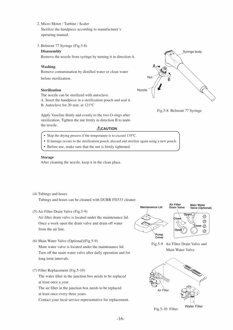
Fig.5-4CleaningofVacuumHandpieceBodyandSalivaEjectorHandpieceBody
Fig.5-6CleaningVacuum/SalivaEjectorLinesFig.5-9AirFilterDrainValveandMainWaterValve
(4)TubingsandhosesTubingsandhosescanbecleanedwithDURRFD333cleaner.
(5)AirFilterDrainValve(Fig.5-9) Air filter drain valve is located under the maintenance lid.Onceaweekopenthedrainvalveanddrainoffwaterfromtheairline.
(6)MainWaterValve(Optional)(Fig.5-9)Mainwatervalveislocatedunderthemaintenancelid.Turnoffthemainwatervalveafterdailyoperationandforlongtermintervals.(7)FilterReplacement(Fig.5-10) The water filter in the junction box needs to be replaced atleastonceayear. The air filter in the junction box needs to be replaced atleastonceeverythreeyears.Contactyourlocalservicerepresentativeforreplacement.
-16-
Fig.5-8Belmont77Syringe
2.MicroMotor/Turbine/ScalerSterilizethehandpieceaccordingtomanufacturer’soperatingmanual.
3.Belmont77Syringe(Fig.5-8)DisassemblyRemovethenozzlefromsyringebyturningitindirectionA.
WashingRemovecontaminationbydistilledwaterorcleanwater
beforesterilization.
SterilizationThenozzlecanbesterilizedwithautoclave.A.Insertthehandpieceinasterilizationpouchandsealit. B. Autoclave for 20 min. at 121℃ApplyVaselinethinlyandevenlytothetwoO-ringsafter sterilization. Tighten the nut firmly in direction B to undo thenozzle.
•Skip the drying process if the temperature is to exceed 135℃.•Ifdamageoccurstothesterilizationpouch,discardandsterilizeagainusinganewpouch.•Before use, make sure that the nut is firmly tightened. StorageAftercleaningthenozzle,keepitinthecleanplace.
Pump Cover
Maintenance LidMain WaterValve (Optional)
Air Filter Drain Valve
Open
Close
Close
Open
Air Filter
Water FilterFig.5-10Filter
A
B
w A
Nozzle
Nut
Syringe body
CAUTION
2-1-1, Higashishinsaibashi,Chuo-ku,Osaka, 542-0083,JapanTEL : +81 6 6213 5945 FAX : +81 6 6212 3680
TAKARA BELMONT CORPORATION
NOTE
Printed in Japan 2011-09BOOK NO. FEFA22D0