YP-TDS: A Tactical Data Simulator For USNA Yard Patrol … · YP-TDS: A Tactical Data Simulator For...
15
YP-TDS: A Tactical Data Simulator For USNA Yard Patrol Craft Jeffrey P. Wilcox [email protected] David J. Stahl, Jr., Assistant Professor [email protected] Computer Science Department United States Naval Academy Annapolis, MD 21402 Abstract The Yard Patrol Craft Tactical Data Simulator (YP-TDS) is an inexpensive, commercial-off- the-shelf hardware and software system providing a tactical display similar to existing systems aboard commissioned warships, for potential use in the educational environment at the United States Naval Academy (USNA). Own-ship position received via the global positioning system (GPS) and simulated contact data generated from a combat simulation scenario is displayed in real time, allowing YP-TDS to be used for student afloat instruction aboard sea-going training craft.
-
Upload
truonghanh -
Category
Documents
-
view
226 -
download
1
Transcript of YP-TDS: A Tactical Data Simulator For USNA Yard Patrol … · YP-TDS: A Tactical Data Simulator For...

YP-TDS: A Tactical Data Simulator For USNA Yard Patrol Craft
Jeffrey P. Wilcox [email protected]
David J. Stahl, Jr., Assistant Professor
Computer Science Department United States Naval Academy
Annapolis, MD 21402
Abstract The Yard Patrol Craft Tactical Data Simulator (YP-TDS) is an inexpensive, commercial-off-the-shelf hardware and software system providing a tactical display similar to existing systems aboard commissioned warships, for potential use in the educational environment at the United States Naval Academy (USNA). Own-ship position received via the global positioning system (GPS) and simulated contact data generated from a combat simulation scenario is displayed in real time, allowing YP-TDS to be used for student afloat instruction aboard sea-going training craft.

Introduction For almost a decade the guiding vision shaping the transformation of our nation's military for the 21st century has been that of information superiority and dispersed, networked force capability [1]. Such a concept is best described as Network Centric Warfare (NCW):
An information superiority-enabled concept of operations that generates increased combat power by networking sensors, decision makers, and shooters to achieve shared awareness, increased speed of command, higher tempo of operations, greater lethality, increased survivability, and a degree of self-synchronization. In essence, NCW translates information superiority into combat power by effectively linking knowledgeable entities in the battlespace [2].
ForceNet describes the evolutionary transformation that brings NCW theory to practice within the US Navy:
The operational construct and architectural framework for naval warfare in the information age that integrates warriors, sensors, networks, command and control, platforms, and weapons into a networked, distributed combat force that is scalable across all levels of conflict from seabed to space and sea to land. ForceNet implements the theory of network-centric warfare [3].
Because the Naval Academy is primarily an educational institution, NCW is addressed pedagogically within the classroom only. In practice, there are no elements of a ForceNet at USNA. Hands-on training in basic navigation, seamanship, and damage control is conducted using Yard Patrol craft (YP). YP’s are 108 ft long twin diesel, rudder and screw surface training ships primarily deployed in Chesapeake Bay waters local to the Naval Academy. With the exception of formation steaming and an occasional simulation of underway replenishment, however, YP's seldom interact. Each YP conducts isolated training operations, essentially independent of other units operating in proximity. Most notably absent is any degree of exposure to afloat operations in the context of a tactical battle situation. While recognizing that YP are not designed nor configured for this purpose, and that the best quality hands-on training can only be accomplished aboard commissioned warships at sea, we claim that YP can and should be used to provide a midshipman's first exposure to elements of NCW. This research project endeavors to validate that concept, and provide a means to embrace the Network Centric Warfare concept in the practical, hands-on professional education at the Naval Academy. Specifically, the goal is to produce a system using commercial-off-the-shelf hardware and custom software that can be fielded afloat aboard YP, capable of simulating sensors, platforms and weapons, in real-time. Such a system has the potential to supplement or facilitate existing Professional Development education and training in every year group: freshman year damage control training, sophomore year navigation practical exercise, junior year tactics instruction, and the leadership experiences gained in senior year summer cruises aboard US Navy warships.

Approach The description of ForceNet as the integration of "warriors, sensors, networks, command and control, platforms and weapons [3]" aptly summarizes the approach of this research project. Using commercial-of-the-shelf hardware and custom designed software, we attempt to integrate real midshipmen and real sensors with simulated weapons, sensors and ships by means of a command-and-control tactical display. With appearance and functionality much like the actual Navy Tactical Data System (NTDS), but intended for use in the context of professional education and training aboard USNA YP craft, the system is named YP-TDS: YP Tactical Data Simulator. In their current configuration the YP provide a platform for afloat training in such areas as seamanship, ship handling, communications and navigation, and to a limited extent, command-and-control situations such as voyage planning and formation maneuvering. We wish to augment this configuration to facilitate training in both damage control and command and control decision making during simulated tactical battle scenarios. Several components are required to achieve this: (1) multiple data entry and display terminals, and (2) scenario simulation software. In effect, the software will simulate a fictional Aegis-equivalent guided missile YP ("YPG", Figure 1), with capabilities far beyond those of an actual YP, in both weapons and sensors.
Figure 1: Real YP and fictional YPG
YP-TDS requirements The system envisioned requires multiple inter-communicating data entry and color display terminals. Midshipman crew would interact with the system by means of mouse and menu driven software, using such system functionality as sensor selection, contact classification, weapons launch, and display of damage control (DC) status. In practice, terminals located in various parts of the ship could be assigned different functions, for example, a terminal controlling sensor use and simulated weapons launch, a terminal used to maintain DC status, and a terminal used to maintain the broad tactical picture. Each of these three functions will be described in general terms below.

Midshipman in the Combat Information Center of their Aegis-equivalent YPG would control a host of simulated sensors and weapons that emulate the functions of their real world counterparts, such as fire control and search radars, hull-mounted sonars, torpedoes, missiles and deck guns, and defensive close-in weapons systems (CIWS), flares and chaff (Figure 2).
Figure 2: Sensors and weapons of a fictional Aegis-equivalent YPG
DC Central would maintain the current damage and damage control status of major ship systems and compartments. Simulated damage incurred by a simulated weapon (missile, shell, torpedo, mine, etc.) would appear on an elevation view of the YP, displaying the ship as a series of equipment or compartment zones, as shown in Figure 3. One possible use for this capability would be in conducting DC training drills. Supervised by a drill monitor, damage control parties could be deployed to the scene of a casualty to combat the casualty and communicate status with DC Central. Fire, flooding, and equipment damage could be annotated according to reports received from the scene.
Figure 3: YP elevation view for maintaining Damage Control status

The tactical display monitored and maintained at a third station could be repeated at any station, providing the broad picture of own ship in the current tactical environment. Symbols representing the position, course, speed and classification of simulated contacts, as detected by simulated sensors, as well as simulated or actual real-world own-ship position as received from GPS, would be plotted on a representation of the local YP operating area. Providing the capabilities described above for each of the three functional stations would involve a number of issues, including (1) choice of networking hardware and communication protocol, (2) design and implementation of a user-interface, (3) digital chart representation, and (4) generation of own-ship and contact position. Each of these areas will be further discussed. YP-TDS System Overview Laptop personal computers running Windows XP are used as the display hardware. Windows XP was chosen as it is the ubiquitous operating system in use, most often found preloaded on systems purchased by the consumer. Software was developed within the Microsoft Visual C++ 6.0 environment and written in C and C++, with both the development environment and the choice of languages being made based on previous experience. Third party libraries are used to implement the color display, networking control, GPS interfacing, and multi-tasking. The specific libraries/APIs used were chosen primarily based on previous use and an abundance of easily available documentation. Implementing the capabilities described in the requirements section was accomplished by breaking functionality into the following series of subsystems:
• User interface • Simulation control • Tactical display • Nautical display • Network Input/Output • Scenario Simulation
A block diagram depicting system functional components and data flow appears in Figure 4. A brief description of each subsystem follows. User Interface: The user-interface design allows the user to access functionality via menus, keyboard and mouse, and to pan and zoom through the simulated NTDS display. Individual menus are provided to incorporate logically separate functionality such as damage control status display and update, weapons and countermeasure selection, and system configuration settings. Interface actions such as contact selection, the ability to determine bearing and range from the tactical display, and accessing contact information are also provided.

Figure 4: YP-TDS Functional components and data flow
Simulation Control: This subsystem forms the heart of the YP-TDS software. Simulated tracks of weapons in flight, aircraft, submarines, neutral vessels, etc., are generated here, as well as own-ship actual position as obtained from a GPS unit. It must communicate with the Nautical and Tactical Display subsystems to produce a dynamically changing NTDS display. The terminal acting as server broadcasts contact position to all other terminals on the network. Terminals acting as clients receive this data and pass it along to the Tactical Display subsystem. Tactical Display: This subsystem displays own-ship position, as well as contact position generated by Simulation Control using standard NTDS symbology for surface, air, subsurface, friendly, threat, etc, contacts. In addition, the contact name, ID number, classification, speed, bearing, position and other data, are be made available by this subsystem. Nautical Display: This subsystem presents a digital chart on which the Tactical Display is superimposed. Internal chart representation allows for zooming and panning. Additional features such as a latitude and longitude grid overlay are provided. Network Input/Output: This subsystem is responsible for sending and receiving the contact data, damage control status data, and simulation control data between the server terminal and multiple client terminals.

Scenario Simulation: This subsystem initializes the simulation control subsystem with all simulated contacts. It is written to permit contacts to be randomly generated, and to accommodate a planned future version of the simulator that reads from a scenario specification file. Implementation Details of the YP-TDS implementation are provided in the following sections, and are presented according to functional subsystem as described above. User interface Graphics are displayed at a resolution of 1024 x 768, in either 16-bit or 32-bit color, using the freely available Allegro graphics API [4]. The user-interface consists of a series of custom-designed menus, buttons and pop-up windows for displaying graphical and textual information and soliciting user input. Various tools are provided to assist in assessing, understanding and managing the ship’s tactical situation, such as the bearing and range cursor and sensor range circles shown in Figure 5.
Figure 5: Bearing and range cursor and sensor range circle
Simulation control The YP-TDS system consists of multiple PC hosts sharing the same contact data. Within a host, YP-TDS software is implemented as a collection of threads, each handling a specific function, and each able to access - and possibly update - the global simulation state. To manage this shared access, a Windows implementation of POSIX pthreads is used [5]. Between hosts, TCP/IP sockets are used to handle communication. Both are described below. The relationship between threads is represented in Figure 6.

Figure 6: Client-server multi-threading
Depending on the role a host plays in the YP-TDS network, it may be one of multiple clients or the single system server. When the server is first established, it will activate a listen thread to detect potential clients attempting to connect via a TCP/IP stream socket. Upon connection, a unique socket is established for the client, a client receive thread is created, and the functional mode assumed by the client (DC status, weapons/sensor control, etc.) is returned. A client receive thread is responsible for all communication with a client until the network connection is broken. The server listen thread remains active, waiting for additional connections, terminating only when the server disconnects. On the client side, after connection to a server, a single client thread is created to communicate directly with its corresponding thread on the server. It is through these two threads that the current simulation state is passed.
Race conditions are possible in both client and server if two threads attempt simultaneous access to shared data. To arbitrate access to shared data a pthreads mutual exclusion lock is employed. A thread wishing to obtain access to shared data must first obtain the lock. Once obtained, other threads attempting access will sleep until the lock becomes available. As a specific example, the GPS thread must update own-ship longitude and latitude, while the main program thread may be simultaneously trying to read them. A mutual exclusion lock prevents reading a position value in an intermediate state of update.
The main program loop of the YP-TDS software is found in the simulation control subsystem. It is an endless, event-driven loop processing user input, updating and distributing contact information, and rendering the screen image. User input from mouse and keyboard are detected and dispatched to the appropriate handler to perform the associated task. On the server, simulated contact course, speed, altitude and position is modified as needed according to the scenario. In turn, code implementing the Nautical Display writes the digitized chart image to a temporary buffer, Contact Display code overlays NTDS symbols on the chart, and Draw Windows code renders windows, menus, and buttons. Finally, before the end of the main loop is reached, the temporary buffer is copied to the screen and displayed to the user.
Own-ship position from GPS A GPS thread on the server handles own-ship position updates as read from a Holux Global Positioning System (GPS) receiver to obtain own ship position, course and speed once per second The GPS unit is connected through a serial port transmitting data at 4800 baud. GPS data consists of ASCII strings in NMEA0183 Marine Interface Standard format, a format easily parsed to yield latitude and longitude [6]. Nautical Display
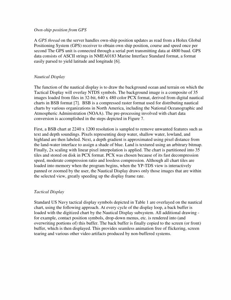
The function of the nautical display is to draw the background ocean and terrain on which the Tactical Display will overlay NTDS symbols. The background image is a composite of 35 images loaded from files in 32-bit, 640 x 480 color PCX format, derived from digital nautical charts in BSB format [7]. BSB is a compressed raster format used for distributing nautical charts by various organizations in North America, including the National Oceanographic and Atmospheric Administration (NOAA). The pre-processing involved with chart data conversion is accomplished in the steps depicted in Figure 7. First, a BSB chart at 2240 x 1200 resolution is sampled to remove unwanted features such as text and depth soundings. Pixels representing deep water, shallow water, lowland, and highland are then labeled. Next, a depth gradient is approximated using pixel distance from the land-water interface to assign a shade of blue. Land is textured using an arbitrary bitmap. Finally, 2x scaling with linear pixel interpolation is applied. The chart is partitioned into 35 tiles and stored on disk in PCX format. PCX was chosen because of its fast decompression speed, moderate compression ratio and lossless compression. Although all chart tiles are loaded into memory when the program begins, when the YP-TDS view is interactively panned or zoomed by the user, the Nautical Display draws only those images that are within the selected view, greatly speeding up the display frame rate. Tactical Display Standard US Navy tactical display symbols depicted in Table 1 are overlayed on the nautical chart, using the following approach. At every cycle of the display loop, a back buffer is loaded with the digitized chart by the Nautical Display subsystem. All additional drawing - for example, contact position symbols, drop-down menus, etc. is rendered into (and overwriting portions of) this buffer. The back buffer is finally copied to the screen (or front) buffer, which is then displayed. This provides seamless animation free of flickering, screen tearing and various other video artifacts produced by non-buffered systems.

Figure 7: BSB raster chart conversion to YP-TDS system format
Table 1: Tactical display symbology
Associated with each contact is a set of variables for storing latitude, longitude, course, and speed. Latitude and longitude are converted to the screen position at which a symbol is plotted. A contact's course determines the direction of the velocity leader, the line emerging from the center of each NTDS symbol, and its speed determines the leader's length. In addition, each track is assigned a Track Number, which can be toggled on or off. Figure 8 is a screen snapshot of the YP-TDS program tactical display.
Surface Aircraft SubSurf Land Base Torpedo Missile Helo
OwnShip N/A N/A N/A N/A N/A N/AFriendly
Enemy
Neutral N/A N/A N/AUnknown N/A N/A N/A
Figure 8: YP-TDS tactical display Network Input/Output The role of this subsystem is two-fold: if the host on which it is running is designated as the server, it will transmit a one kilobyte structure containing data on the tracked contacts (latitude, longitude, altitude, course, speed, damage control information, etc.). In its current implementation the YP-TDS system can track no more than forty contacts. Client hosts receive the state variable and update their particular display accordingly. After receipt a client will reply with a “state received” acknowledgement string. The server will not attempt to send updated state to a client until it has received a reply from the previous update. A client designated to display the ship’s damage control status can transmit a string conveying damage control information, encoded to include both the damage control zone (location of the damage) and the type of damage (fire, flooding, or structural). Figure 9 shows the YP-TDS DC status board display with the ship having suffered various casualties.

Figure 9: Damage control status board showing various casualties
Scenario Simulation This subsystem’s purpose is to load and initialize the training scenario with both preset and pseudo-random data. The preset data can be specific ships and aircraft loitering at a specific location, with specific names and performing specific activities. The pseudo-random data functions by randomly generating contacts based on preset location traits (air traffic corridors, shipping lanes, etc.) This facet of the Scenario Simulation guarantees that every training simulation will be slightly different. In the current implementation, contact locations are hard-coded and cannot be changed externally. No new platforms can be added, and no starting positions, names, bearings, etc. can be altered. However, future versions will feature fully configurable platforms, missions, and scenarios specified in an ASCII text configuration file. Results and Lessons Learned YP-TDS provides USNA YP craft with a tactical display and the means to simulate combat, damage control, and command and control decision making situations, using a set of up to four PCs communicating in a local area network. Each PC host functions as an access point into the YP-TDS system. A student user can launch simulated weapons, employ simulated sensors, and keep track of damage control. From the bridge, a Midshipman Officer of the Deck can maintain awareness of the tactical picture and the damage control status of his ship.

In another location a neutral referee can enter or monitor simulated damage to the ship, and upon receiving reports that that damage has been repaired, can update the system. A ship can be virtually sunk by simulated attacks. The ship’s position is accurately displayed on each of the PCs using the Global Positioning System.
The largest hurdles in designing such a project is not only removing bugs, and ridding the system of unforeseen shortcomings, but also optimizing code for speed, reliability and providing the user with an easy to use interface. This is a daunting task when simultaneously adding modules and constantly updating functional subsystems. The solution to the difficulties was to program the YP-TDS system in sections. For example, the nautical system was written as a separate program, as was the GPS system. Only after both were thoroughly debugged and tested were they added to the actual YP-TDS program. Other hurdles dealt with limitations of the computer software to communicate with the GPS hardware, and handling different computers transmitting and receiving data across the network at different speeds. Because of the way the Nautical charts are loaded, and because their format must undergo a lengthy preprocessing before it can be used, only one operating area can be shown. This limitation’s only solution is to use a better chart format, one that does not require as much preprocessing.
Other limitations include a fixed number of contacts the YP-TDS system can handle, at present limited to forty, including own-ship. In the future, this number will be dynamic, and automatically adjusted to allow as many contacts as is limited by the server computer’s memory and processing speed. The system also lacks some basic user friendly functions such as a right-click pop-up menu allowing a user to quickly update or display information about a track.
The deficiencies and limitations of the YP-TDS system pale in comparison to the features it provides. Future versions of this system will address these limitations as well as add ever more functionality to support the goal of embracing the Network Centric Warfare concept within the Naval Academy training curriculum. Future work Although the YP-TDS system delivers superb performance there is still room for improvement. The groundwork is laid for the expansion of this system from deployment aboard a single YP to use on several YP’s, with communications via a wireless network. Existing HF Frequency Shift Keying (FSK) capable radios already installed on the YP could be used to allow every YP to electronically report its position as well as other simulation data to all other YP in a wide area network. Among its current limitations is the inability of the Nautical Display to display other than the general vicinity of the Naval Academy. This limitation is intentional, as use of the raster-based BSB charts used by the Nautical Display was intended solely to prove the YP-TDS system is feasible. They are eventually to be replaced with a Vector Product Format (VPF) chart. VPF allows for greater accuracy and much better control of what chart features to

display (e.g., it would be easier to filter in or out such data as navigational aids, gridlines, and depth sounding numbers). Currently, the charts must be pre-processed before use, but future upgrades might feature charts displayed on the fly, perhaps using the OpenGL graphics API. There is no artificial intelligence (AI) driving the simulated contacts as of yet. Aircraft and ships simply move along their pre-set bearing at a fixed speed. Weapons do not realistically track nor impact their target. Future work will allow all contacts to behave in a realistic fashion, including computer controlled hostile contacts that will attempt to meet their own mission criteria, including but not limited to destroying a YPG battle group. Currently there is no means to change the simulation scenario. The position, bearing and other traits of all platforms, as well as battle group composition and weapons load out are fixed. Future versions will allow for a script-like configuration language to be used to custom tailor the scenario to meet a multitude of training needs. Since this simulation will eventually take place aboard a YP, it would improve realism if the environment better seemed like a combat environment. To do this, a YP-TDS laptop might be patched into the YP ship’s announcing system, giving the ability to play various sound effects throughout the YP - for example, the sound of a missile flyover or launch, or a deck gun firing with its shell casing clattering on the deck.

References 1. Chairman of the Joint Chiefs of Staff (1996). Joint Vision 2010, Joint Chiefs of Staff, Washington, D.C. 2. David S. Alberts, John J. Gartska, Frederick P. Stein, CCRP (1999). Network Centric Warfare: Developing and Leveraging Information Superiority, 2nd Edition (Revised) 3. VADM Richard W. Mayo, USN, VADM John Nathman, USN, US Naval Institute Proceedings (2003). ForceNet: Turning Information into Power 4. Shawn Hargreaves (1998). Allegro: Freeware Graphics Libraries http://alleg.sourceforge.net/ 5. John E. Bossom (1998). POSIX: Threads Library for Win32 http://sources.redhat.com/pthreads-win32/ 6. A. Riazi (2003) Add GPS Support to Your Desktop http://www.codeproject.com/system/gps_support.asp 7. Frank Warmerdam (2002). BSB Reader [email protected]