Yossi kichtenstein, Yossi alka, Aharm Aharon
12
Yossi kichtenstein, Yossi alka, Aharm Aharon IBM Israel Science and Technology Haifa 31905, ISRAEL {laor, yossi, aharon}@haifasc3.vnet.ibm.com Abstract A few simple Expert-System techniques have been invaluable in developing a new test pro- gram generator for design verification of hard- ware processors. The new generator uses a for- mal declarative model of the processor architec- ture; it allows generation of test programs for a variety of processors without duplication of ef- fort. A heuristic knowledge base representing knowledge about testing techniques allows gener- ation of incisive tests. This knowledge base cap- tures information that until now has been kept by experts and has not been formally documented. Furthermore, the complexity, changeability and non-visibility of architectural details and testing Several architectures have been modelled by the system. They include a CISC processor, a float- ing point unit of an S/390 computer, a vector floating point unit, and four implementations of a PowerPC-like architecture. The j&-St silicon re- alizations of two of the designs have already been shown to comply with the architectural specifica- tion. Other designs are still under testing. There are also first indications that using the new tech- nology reduces verification period and decreases time to market: The verification of a high-end RISC processor required six calendar months, in contrast to fifteen months needed for verifying a simpler processor technology. using a previous test generation Introductisn The goal of processor verification is to ensure equiva- lence of a processor and its architectural specification. This goal can be achieved either by a formal proof or by exhaustive simulation. However, state of the art formal techniques and the complexity of processors render the formal approach incomplete for large indus- trial applications. Moreover exhaustive simulation is impossible as the test space is enormous. In practice, design verification is carried out by simulating a rel- atively small subset of selected test programs. These are run through the design simulation model, and the results are compared with the output predicted by the architecture simulation model. Systems that generate tests for processor verification (Aharon et ad. 1991), (Chandra & Iyengar 1992) typi- cally sustain a high degree of complexity and change- ability. The complexity of processor architectures - hundreds of instructions, dozens of functional units (Struble 1984),(0ehler & Groves 1990) - and their in- formal description are reflected on the generation sys- tem. Furthermore, design verification gets under way when the architecture is still evolving and a typical test generation system undergoes frequent changes. The architecture and testing knowledge are modelled pro- cedurally in the generation system and their visibility is low. This worsens the effects of the complexity and changeability. A new approach to test generation for design verifi- cation is proposed in this paper. It is termed Model- Based Test-Generation as its heart is a formal model of the architecture. The complexity, changeability and invisibility are tackled by separating logic from con- trol, or more specifically, separating the the architec- tural model from the architecture-independent genera- tion process. The complexity of the system is reduced by this separation; the architecture is more visible in the formal declarative model; and likewise, the change- ability problem is eased considerably by the new mod- elling approach. The Model-Based Test-Generation approach allows the incorporation of complex testing knowledge. A knowledge base is used in conjunction with the ar- chitectural model; it includes heuristics which repre- sent testing-engineers expertise. This knowledge base is employed to generate incisive or probing test cases and allows experts to add knowledge in a local and relatively simple way. The rest of this paper is organized as follows. Previ- ous techniques for automatic test generation for design verification are summarized in section Test Program Lichtenstein 83 From: IAAI-94 Proceedings. Copyright © 1994, AAAI (www.aaai.org). All rights reserved.
Transcript of Yossi kichtenstein, Yossi alka, Aharm Aharon

Yossi kichtenstein, Yossi alka, Aharm Aharon
IBM Israel Science and Technology Haifa 31905, ISRAEL
{laor, yossi, aharon}@haifasc3.vnet.ibm.com
Abstract
A few simple Expert-System techniques have been invaluable in developing a new test pro- gram generator for design verification of hard- ware processors. The new generator uses a for- mal declarative model of the processor architec- ture; it allows generation of test programs for a variety of processors without duplication of ef- fort. A heuristic knowledge base representing knowledge about testing techniques allows gener- ation of incisive tests. This knowledge base cap-
tures information that until now has been kept by experts and has not been formally documented. Furthermore, the complexity, changeability and non-visibility of architectural details and testing
Several architectures have been modelled by the system. They include a CISC processor, a float- ing point unit of an S/390 computer, a vector floating point unit, and four implementations of a PowerPC-like architecture. The j&-St silicon re- alizations of two of the designs have already been shown to comply with the architectural specifica- tion. Other designs are still under testing. There are also first indications that using the new tech- nology reduces verification period and decreases time to market: The verification of a high-end RISC processor required six calendar months, in contrast to fifteen months needed for verifying a
simpler processor technology.
using a previous test generation
Introductisn
The goal of processor verification is to ensure equiva- lence of a processor and its architectural specification. This goal can be achieved either by a formal proof or by exhaustive simulation. However, state of the art formal techniques and the complexity of processors render the formal approach incomplete for large indus- trial applications. Moreover exhaustive simulation is
impossible as the test space is enormous. In practice, design verification is carried out by simulating a rel- atively small subset of selected test programs. These are run through the design simulation model, and the results are compared with the output predicted by the architecture simulation model.
Systems that generate tests for processor verification (Aharon et ad. 1991), (Chandra & Iyengar 1992) typi- cally sustain a high degree of complexity and change- ability. The complexity of processor architectures - hundreds of instructions, dozens of functional units (Struble 1984),(0ehler & Groves 1990) - and their in- formal description are reflected on the generation sys- tem. Furthermore, design verification gets under way when the architecture is still evolving and a typical test generation system undergoes frequent changes. The architecture and testing knowledge are modelled pro- cedurally in the generation system and their visibility is low. This worsens the effects of the complexity and changeability.
A new approach to test generation for design verifi- cation is proposed in this paper. It is termed Model- Based Test-Generation as its heart is a formal model of the architecture. The complexity, changeability and invisibility are tackled by separating logic from con- trol, or more specifically, separating the the architec- tural model from the architecture-independent genera- tion process. The complexity of the system is reduced by this separation; the architecture is more visible in the formal declarative model; and likewise, the change- ability problem is eased considerably by the new mod- elling approach.
The Model-Based Test-Generation approach allows the incorporation of complex testing knowledge. A knowledge base is used in conjunction with the ar- chitectural model; it includes heuristics which repre- sent testing-engineers expertise. This knowledge base is employed to generate incisive or probing test cases and allows experts to add knowledge in a local and relatively simple way.
The rest of this paper is organized as follows. Previ- ous techniques for automatic test generation for design verification are summarized in section Test Program
Lichtenstein 83
From: IAAI-94 Proceedings. Copyright © 1994, AAAI (www.aaai.org). All rights reserved.

Generation. We describe the problematic aspects of generation systems and the motivation for the Model- Based approach (section Motivation) and analyze man- ually written tests (section Knowledge Acquisition). The model and generation scheme are described in two stages, basics first (section Basic Modedling and Gen- eration) and the complete model then (section Further Modelling and Generation). An actual Model-Based Test-Generation system is described (section The Sys- tem), and the results of its usage concludes this paper (section Results).
Test Program Generation Processor design verification is usually carried out by simulating a relatively small subset (as compared to the exhaustive set) of selected tests. These tests are run through the design simulation model, and the re- sults are compared with the output predicted by the architecture specification. A behavioral simulator rep- resents the architecture; it is normally written for soft- ware development purposes, prior to having the actual hardware. Following this approach, processor verifica- tion consists of two steps. The first is the selection or generation of tests. The second step is a comparison between results predicted by the two levels of simu- lation models. Both simulators are provided with the selected tests as stimuli, and the simulators final states are compared.
Design verification by manually written tests is not cost effective. Typically, one to two thirds of a design effort are dedicated to verification (Pitter, Powers, & Schnabel 1982). Furthermore, many of these tests are simple, as test engineers find it difficult to define com- plex situations. The automation of test program gen- eration has increased productivity and in recent years has also provided better quality. Though being much more productive writing tests manually, early auto- matic test program generation was too limited (Tran, Forsberg, & Lee 1982), (Bellon 1982). The standard approach was to use pseudo random selection of in- structions and data from predefined (or static) tables. This yields a restricted space of test programs.
Alternative approaches tie simulation and genera- tion to gain complex tests. The generation process is interleaved with the instruction execution, the inter- mediate processor state is used during the generation process, and decisions are made dynamically. The gen- eration employs pseudo random selection with bias to- wards boundary and exception conditions. A simple example is the generation of data for an ADD instruc- tion: these are biased to exercise frequently enough the condition sum-is-zero and the exception overflow. Biasing is similar to the partitioning of the input do- main suggested in (Weyuker & Ostrand 1980): the gen- eration is directed to select inputs (i.e., tests) from all partitions, in particular from small input classes.
IBM’s Random Test Program Generation (RTPG) is the first example of a dynamic biased pseudo random
generation for processor design verification (Aharon et al. 1991). More successful experience with similar sys- tems is reported by recent papers. For example, AVP- GEN (Chandra & Iyengar 1992) was used in verifying different IBM S/390 processors. Another example, is a static test generator augmented with dynamic model demons which was used in verifying DEC’s NVAX CPU (Anderson 1992).
A typical generation system comprises an instruction level architectural simulator, an instruction generator which includes biasing capabilities, models and biased- generators for special functional units (e.g., storage control unit) and a user-interface software which al- lows users to direct the test generation.
Motivation The development of random test program generators (as described in the previous section) is prone to the usual software development difficulties. Follow- ing Brooks (Brooks 1987), three (out of the four) es- sential difficulties may be identified in test generation projects: complexity, changeability, invisibility.
Complexity: Computer architectures are complex. A typical architecture includes hundreds of instruc- tions, a few dozens of resources (main memory, general- purpose registers, special-purpose registers), and com- plex functional units (e.g., floating point, address translation , external interrupt mechanism). Architec- tures are defined informally (in English), and a typical description is a few hundred pages long. Furthermore, the procedures used to test architectures are another source of complexity. These are usually intricate proce- dural descriptions which involve resource initializations and instruction sequences.
Changeability: Design verification starts when the architecture is still evolving. Changes in architecture specifications are quite frequent, usually described in- formally, and their consequences over the generation system are difficult to identify. Furthermore, many of the changes in the generators are due to the evolving testing knowledge accumulated through the validation process itself. New testing needs rise frequently as a consequence of previous testing results and uncovering of design errors.
Invisibility: Both architecture and testing knowl- edge are modelled in generation systems. The architec- ture is modelled by both the simulation and generation blocks of the generator. Testing knowledge is embed- ded in the generation procedures of the systems. Mod- elling of both is procedural and tightly inter-connected. Its visibility is thus low.
Our approach is to tackle the complexity, change- ability and invisibility by separating the knowledge from the control (following (Kowalski 1979)). The knowledge includes a formal description of the archi- tecture and a heuristic procedural representation of the testing knowledge; both reside on an external data- base. The control is the architecture-independent gen-
a4 IAAI-94

eration process; it may be viewed as an interpreter of the architectural model. The complexity problem is thus lessened by the strong separation between data- base and control. Furthermore, keeping the architec- tural simulator separate from the generator removes a major source of system’s complexity. The invisibility is decreased by the formal and declarative modelling of the architecture. Confining most changes to the data- base considerably alleviates the changeability problem.
The fact that the architecture is represented only in the external data-base gives the proposed approach its name - model-based test-generation. To the best of our knowledge, this is the first system to use model-based techniques for design verification. Following model- based approaches in other domains (in particular in diagnosis, (Davis 1984), (Reiter 1987) and (De Kleer & Williams 1987)), t wo differences should be empha- sized: our model describes the architecture but does not include the structure of the implementation; we have neither identified nor used first principles of the generation domain.
The external data-base contains also a heuristic knowledge base representing testing knowledge. It opens the generation system for users accumulative ex- perience, and enables the tool to follow the progress of the testing process. Furthermore, it allows migration of testing knowledge from one architecture and design to another.
Knowledge Acquisition Hand written test programs have been analyzed as a basis for the design of our system. Experienced test engineers were asked to summarize hundreds of test programs. They provided us with descriptions of high level verification goals, detailed verification tasks and a dozen or so groups of test programs realizing these verification tasks. The detailed analysis of the data can be found in (Lichtenstein, Malka, & Aharon 1993); here, only some observations from that analysis are given.
Verification tasks are described using terms from two domains. The first, the operation domain, is that of operands, instructions and sequences of instructions. The second, hardware domain, is the set of hardware facilities which include resources (e.g., register sets, memory) and functional units (e.g., address transla- tion, cache, pipeline). Some tasks specify instances in the operation domain; others associate between ele- ments of the operation domain and resources or events related to functional units.
The verification tasks described above indicate that it is necessary to model resources and instructions. In addition, verification tasks use terms as the address of the operand and terms related to different aspects the computation carried out by the instruction. Therefore, an instruction should be modelled semantically rather than syntactically. This is a major deviation from pre- vious generation systems that emphasized the syntax
of instructions. The tasks also unveil important attributes of the op-
eration domain. In particular, length, address and data are essential for operands; exceptions, condition codes and special results are pertinent to instructions. Also, the notion of a data-type of the data values an operand can take is implied. Furthermore, some aspects of the verification tasks are complex and procedural; we con- cluded that this would be modeled in a procedural and open knowledge base.
Finally, test programs can be classified by the in- terdependencies embedded in them. These dependen- cies can be ordered in increasing complexity as follows: within-operand, inter-operand and inter-instruction. The latter can in turn be ordered as short and long sequences.
ask Modelling and Generation
Test programs are sequences of instruction instances which use the architecture resources. This section describes by example the model of instructions and explains the basic generation scheme. The next sec- tion completes the modelling details and brings the full generation procedure. The full modelling scheme and its relation to processor modelling and compilation techniques appear in (Lichtenstein, Malka, & Aharon 1993). Appendix A gives somewhat more formal de- scription of the syntax and semantics of the instruction model.
Memory and register resources are described by an ISIS (Barbacci 1982) memory declaration; it includes the memory name, the size of memory cells, and the range of addresses. For example, a main memory may be 232 addressable bytes: Main- Memory [0x00000000:OxFFFFFFFF] (0:7). Word regis- ters, as a second example, may be an array of sixteen four-bytes storage units: Word-Register[O:15](0:31).
Instructions are modeled as trees at the semantic level of the processor architecture. An instruction is described by a tree with a format and a semantic pro- cedure at the root, operands and sub-operands as in- ternal nodes and length, address and data expressions as leaves. The expressions use the instruction’s format as alphabet and represent the static relations between operands. These relations do not change; they are the same before and after the execution of an instruction. Thus, they are central to the automatic generation of tests and are modelled declaratively. Address expres- sions denote immediate fields, registers, and memory storage in various addressing modes. Length expres- sions denote the size of storage used by the operand. Data expressions are just literals denoting data-types. Declarative modelling of the full semantics would have made automatic generation too complex to be practi- cal. The approach employed here gives enough power to generate useful and revealing test programs whilst keeping the complexity of the generator and the model reasonable. Moreover, the time needed for generation
Lichtenstein 85

is kept within acceptable limits.
Example: An Add Word Instruction Tree
Add Word is one of the simplest instructions in a typi- cal CISC architecture. Informally, the meaning of this instruction is to add the second operand to the first one and to place the sum at the first operand’s loca- tion The instruction tree is depicted by figure 1 and by the subsequent list. The resources assumed are a main memory, base-registers and word-registers.
Figure 1: Add-Word
Instruction: Semantic procedure: Add-Word0 Format: AW-OPCODE Wl, D2, B2
First operand (represents the register used both as a source and target): Sub-operand:
L: 4; A: register(W1); D: Signed-Binary.
Second operand base register and operand):
(represents the memory storage, displacement comprising the source
Sub-operand:
?: zbntents(register(B2))+value(D2); D: Signed-Binary.
Sub-operand:
k: ?A-field(D2). D: Displacement-Data-Type.
Sub-operand:
i: fkgister(BZ)* D: Address-Dais-Type.
To further illustrate the inter-operand relationships and the complexity of instructions, a relatively com- plex CISC instruction is given in appendix B (Move Character Long).
Generation
An instruction tree describes a set of instruction- instances. The length, address and data expressions of the model are replaced by length, address, and data instances to form an instruction instance. This re- placement must be consistent with the relations de- scribed by the expressions. Namely, if fields and re- sources are shared by several sub-operands, the values selected for them must be identical. The following sec- tion describes consistent instances and the process of generating them from instruction trees.
The generation scheme traverses the instruction tree in a depth first order. At the root and internal nodes, no action is taken. At the leaves, length, address and data instances are either already set by previous se- lections or are randomly selected from the semantics of the corresponding expressions. This scheme ensures consistency of the generated instruction instances. At this level of detail, the generation scheme is almost identical to a Prolog interpretation of the instruction tree.
Example: An Add Word Instruction Instance
The instruction tree (given in sectionEzampde: An Add Word Instruction Tree) is traversed in depth first order; the node labels of figure 1 denote this generation order. An instance of this Add Word instruction is depicted by figure 2.
4 7 4 1 2 - 0100
5F93A16B 15EA917c
000010008100 000010008000
Figure 2: Add-Word Instance
This instruction instance sets both the syntax and the semantic entities of the Add Word instruction. The syntax is a format instance (AW 7, 0100, 9). The se- mantic domain includes the contents of word register number 7 (SF93Ai6B), the contents of base register number 9, (000010008000), and the contents of the main memory word 000010008100 (lSEAQl7C).
86 IAAI-94

rther odelling and Generation
The declarative architectural model lacks the ability to describe complex aspects of the architecture and to incorporate testing knowledge. Furthermore, the basic generation scheme does not clarify how consistency is kept in selecting length, address and data instances. The modelling of the heuristic procedural knowledge base, its relation to instruction trees and the full gen- eration details are described below.
Testing nowledge - Generation and Validation Functions
Generation and validation functions are used as ba- sic blocks of the generation scheme. These func- tions implement a generate-and-test strategy alongside the traversal of instruction trees. The testing knowl- edge model is procedural rather than declarative. We believe that the complexity and diversity of testing knowledge is such that declarative modelling is diffi- cult if not impossible. The classes and examples of testing knowledge given below are simplified for ease of exposition.
Generation functions are used by the generation scheme, while traversing an instruction tree. When a node is traversed all the generation functions associ- ated with it are invoked. The outputs of these func- tions are used to generate the instances of the current sub-tree. Generation functions serve various purposes:
Modelling Condition Codes (inter-operand verifica- tion tasks): An instruction execution may result in the setting of condition code bits. This effect is part of the instruc- tion’s specification and is modelled by the semantic procedure. Moreover, the condition codes partition the input domain of the instruction. As it is a com- mon testing knowledge to use this input partitioning, a generation function may bias the data of operands to exercise all condition codes. Program Exceptions are modeled in the same manner.
Modelling Program Exceptions (inter-operand): Program exceptions are exceptional conditions raised by instruction execution. They are modelled by the semantic procedure and may be viewed as input partitioning.
Modelling Procedural Aspects of Resources (inter- instruction): The modelling of resources as registers and memory ranges is too simplistic for an actual architecture. In particular address translation and cache mechanisms are common in computer architectures. Generation functions are used to incorporate inputs which test these mechanisms into test programs.
Data Type Special Values (within operand): The domain of (typed) data instances may also be partitioned. Again, it is common to require that representatives of all data-type partitions be tested.
0 Modelling Design Implementation: Various aspects of the hardware design are usually taken into consideration in the verification process. Although these aspects are not considered part of the architecture, their testing is considered essential.
Validation functions are used by the generation scheme. After generating a sub-instance-tree, the val- idation functions associated with the corresponding sub-instruction-tree are invoked. If any of them returns a REJECT answer, the generation results of the sub- tree are retracted and the sub-tree is traversed again. Validation functions serve different purposes: 1) Im- posing restrictions that are not modeled by the length, address and data expressions on instruction instances. 2) Preventing instruction instances from causing pro- gram exceptions. 3) Validating typed data instances.
Generation and validation functions are the build- ing blocks of the heuristic knowledge base and pro- vide for an open system (section Motivation). The fact that generation functions are allowed to produce only simple data-types (i.e., length-instance, address- instance, data-instance), enables a knowledge engineer to express his (or her) testing knowledge in a natu- ral and local manner. Yet, the ability to generate sets of such instances and to associate functions with instructions, operands and sub-operands gives these functions the desired expressiveness. Had generation functions allowed to create full instruction-instances, they would have been too complex to be written by users. Their simplicity allows openness and make it possible to model the evolving testing knowledge.
Example: Add Word Generation Functions
The Add Word instruction tree is augmented with gen- eration functions. This should illustrate the various objectives which may be achieved by generation func- tions; for example:
GenarteSumZeroForAw
CheckHalfWordAdders
1 GenerateHith4iss
GencrateUnsignedBinExtremes
Figure 3: Generation Functions for Add-Word
Modelling Condition Codes: The execution of ADD WORD sets the condition code to SUM IS ZERO, SUM IS LESS THAN ZERO or
Lichtenstein 87

SUM IS GREATER THAN ZERO. The function GEN- ERATE SUM ZERO FOR AW is associated with the root of the instruction tree. It generates two (as ran- dom as possible) data-instances for the appropriate sub-operands, such that their sum is zero.
Modelling Program Exceptions: ADD WORD may cause an EFFECTIVE ADDRESS OVERFLOW exception; this happens when the con- tents of the base register points to one memory seg- ment, while the address formed by the addition of that register and the displacement points to a dif- ferent segment. A generation function GENERATE EFFECTIVE ADDRESS OVERFLOW is associated with the second operand. It generates two data-instances for the appropriate sub-operands which cause an EF- FECTIVE ADDRESS OVERFLOW.
Modelling Procedural Aspects of Resources: An address-instance may either be resident in the cache (HIT) or not (MISS). Likewise, the address and length instances of a sub-operand instance may ren- der its least-significant byte as either HIT or MISS. The function GENERATE HIT MISS includes knowl- edge about the cache mechanism and is associated with the memory address of the second operand. It generates address and length instances which ran- domly exercise one of the hit/miss combinations.
Data Type Special Values: The function GENERATE UNSIGNED BINARY Ex- TREMES is associated with the two unsigned-binary data leaves. It generates data instances, which are selected randomly from the values OXFFFFFFFF, 0~00000000 and near values .
Modelling Design Information: A generation function associated with the root, may test the carry-look-ahead mechanism (Ward & Hal- stead 1990). It produces data instances for the un- signed binary leaves that result in different carry patterns on the look-ahead boundaries. For ex- ample, in the case of two half-word adders, the data values OOOOFFFF and 00000001 exercise the carry passed between the two adders. The function CHECK HALF- WORD ADDERS represents knowledge about the implementation of the Arithmetic and Logic Unit.
Generation
Test generation is divided into two procedures: GENERATE-TEST (figure 4) and GENERATE (figure 5). The former uses a dynamic generation process (see sec- tion Test Program Generation), and the latter is an elaboration of a depth-first traversal of an instruction- tree with backtracking.
A resource manager exists in the background of the generation process. It, manages the processor’s state which is essential for the dynamic GENERATE-TEST algorithm. It is also essential in GENERATE-TEST for
Initialize the minimal processor state WHILE Number-of-instructions < N
Select au instruction Denote its model by Instruction-Tree GEN : Instance = Generate(Instruction-Tree,Empty) Simulate Instance by its Semantic-Procedure IF Instance is executable
THEN Write it to the test file Increment number-of-instructions
ELSE Retract Instance Restore the processor’s previous state
IF retry-limit not exceeded THEN go-to GEN ELSE Abort
return Success
Figure 4: Generate-Test(N)
Invoke Node ' s generat ion functions Add their outputs to Kept-Outputs
IF Node is internal THEN FOR each of Node’s immediate descendants
Generate(Descendant, Kept-Outputs) IF Reject is returned
THEN Restore Kept-Outputs IF retry limit not exceeded
THEN GeneratecDescendaut, Kept-Outputs)
ELSE Return Reject ELSE return Accept
ELSE (Node is a leaf) Select one of Node’s Kept-Outputs IF there is no such output
THEN Select randomly au instance from
the Node’s expression semantics IF the instance does not
satisfy this expression THEN return Reject ELSE return Accept
Invoke Node ’ s validat ion functions IF any of them returns Reject
THEN Return Reject ELSE Return Accept
Figure 5: Generate(Node, Kept-Outputs)
88 IAAI-94

resolving address expressions. Generation and valida- tion functions query the resource manager about the allocation and contents of resources. This information is used to select resources and validate the instruction tree expressions.
The System A Model-Based Test-Generator has been developed fol- lowing the techniques described in this paper. As de- scribed in figure 6, the system comprises an architec- tural model, simulator, architecture independent gen- erator and user-interface. The generator and user- interface have been implemented in C, each snanning
1
about 30,000 lines of code. A detailed description the system can be found in (Lichtenstein, Malka, Aharon 1993).
. . . . . . . . . . . . . . * . . . . . . . . . 1 . . . . . . . . . . . . . . . . . . . . . . . . . . . . . . . . . . . . . I . . . . . . . . . . . . . . . * . . . . . . . . . . . . . . . . . . . . . . . . . . . . . . . . . t . . . . . . . . . . . . . . . . . . . ...
Test Programs
Figure 6: System components and interrelations
The architectural model contains a specification
of &
of instructions, resources and data types as defined in ap- pendix A. The heuristic knowledge base includes gener- ation and validation functions implemented in C (sec- tion Further Mode/ding and Generation). Both types of data are stored in a frames data-base where classes for instructions, operands, fields, resources, data types and functions are defined. A skeleton of the class hier- archy is given in figure 7.
The population of the data-base is carried out by a knowledge engineer familiar with the specific archi- tecture. The knowledge engineer, uses the informal architecture books (written in English) as a source for the architecture model. The testing knowledge is ei- ther written by the knowledge engineer or by testing experts who are familiar with the modelling scheme.
A Motif based user interface offers extensive con- trol over the generation process. Apart from the abil- ity to determine the number of instructions in each test and to initialize resources, the user can direct the generation at three levels: Global, Local and Specific. These levels are characterized by the scope of the con- trol they offer. Global selections pertain to the genera- tion process as a whole; local selections apply to every instance of an instruction whenever it is generated; fi-
- INSl-RUCTION_DOMAINO
INSTRUCTION(apco&fat,operandscond_c~s,e~eptio~~s~tio~, generation_functions)
OPERAND(data_type~dss~eng~~so~,~g~en~ub_~r~~.
generation-functions)
FJlEL,D(mnemonics,data_type)
DATA_DOMAINOength.~glignmentbounds.values,v~~tion_~~~o~,
t
generation_functions) ADDRESS0
SCALAR0
- RESOURCEl_DOMAJN(size)
t
[email protected],array_bounds,bit_bounds,synonyms)
MBMORY(address_ranges)
- PUNCTIONS_DOMGIN@rotatype,source_code)
t
GENJ3RATION(input_parameters,outputgaramet)
VALIDATION0
Figure 7: A class hierarchy skeleton
nally, at the specific level selections bear on particular instances of generated instructions. The generator in- terprets many user directives as selection of generation functions and values for their input parameters. In this manner, the user controls the generation functions in- voked in the GENERATE procedure of section Further Modedling and Generation. Figure 8 is an example for the global selections window.
Great importance is attributed to the efficiency of automatic test generation. Therefore, modifications had to be applied to the instruction generator in or- der to make it efficient. Constraint solvers have been introduced to avoid superfluous backtracking, due to violation of relations between values of leaves in the instruction tree (as specified by length and address ex- pressions). A solver is activated at appropriate inter- nal nodes of the instruction tree and simultaneously assigns values to the leaves such that the relations are not violated.
Results
IBM has invested several million dollars in develop- ing the Model-Based Test-Generation system. Most of the investment went into testing-knowledge acquisi- tion and development; the rest was put in developing the test generator itself. There are first indications that using the new technology reduces verification pe- riod and decreases time to market. In particular, the verification of a high-end RISC processor required six calendar months, in contrast to fifteen months needed for verifying a simpler processor using a previous test generation technology (Aharon et al. 1991).
The test generation system has been used to model
Lichtenstein 89

Figure 8: Global Selections Window
several processor architectures and verify their imple- mentations. Table 1 summarizes current verification experience.
The Processor column indicates architecture type: PowerPCis a state of the a.rt architecture of a Reduced Instruction Set Computer (RISC). The PowerPC pro- cessors implement, a super-set of this architecture and the plus signs indicate the complexity of the design. Two of the processors are Float’ing Point Units (FPU); CISC st,ands for Complex Instruction Set Computer.
The Defects and Stage columns indicate the actual results. The number of design defects is a very rough measure of the complexity of the design and its verifi- cation. The ultimate measure of success is the number of silicon realizations needed to achieve a fully func- tional processor. For the two verification processes which have been already completed, the first silicon realizations are fully functional. For complex proces- sors, t,his was a practical impossibility using manual test production. It is considered a major achievement
when automatic test generation is used. The architectures modelled differ by their instruc-
tions repertoire and structure, inter-operand relations, resources and functional units. Each architecture con- sist of hundreds of instructions, is specified in a multi- volume architecture-book, and requires costly and in- tricate verification scheme. The most complex archi- tecture modelled to date includes about 650 instruc- tions, over 120,000 lines of C procedures representing testing knowledge, and resides in an 8 megabyte data- base.
The diversity of the architectures modelled has ne- cessitated changes in the modelling described by this paper. For example: the length and address expression languages have been expanded; a class containing se- quences of instructions has been introduced to express pre and post-conditions for the generation of certain instruction instances; validation functions can be ac- tivated either before or after simulating the generated instruction instance. All in all, it seems that the ba-
90 IAAI-94
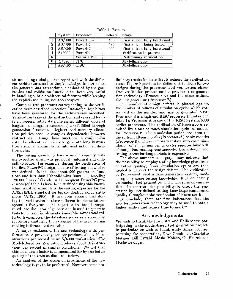
Table 1: Results
I System I Processor I Defects I Stage I 1 AS 400 PowerPC+ 2 AS/400 PowerPC++ 3 AS 400 PowerPC+++ 4 S/6000 PowerPC+++
450 First silicon fully functional 480 First silicon being tested 600 First silicon fully functional
- Verification in process 5 *-
I Vector FPU - Preliminary verification
6 s/390 FPU - Modelling only 7 AS/400 CISC - Modelline: onlv
I 1 , I I I v Y I
sic modelling technique has coped well with the differ- liminary results indicate that it reduces the verification ent architectures and testing knowledge. In particular, costs. Figure 9 provides the defect distributions for two the generate and test technique embodied by the gen- designs during the processor level verification phase. eration and validation functions has been very useful One verification process used a previous test genera- in handling subtle architectural features while keeping tion technology (Processor-A) and the other utilized the explicit modelling not too complex. the new generator (Processor-B).
Complex test programs corresponding to the verifi- cation tasks described in section Knowledge Acquisition have been generated for the architectures modelled. Verification tasks at the instruction and operand levels (e.g., representative data instances, different operand lengths, all program exceptions) are fulfilled through generation functions. Register and memory alloca- tion policies produce complex dependencies between instructions. Using these functions in conjunction with the allocation policies to generate long instruc- tion streams, accomplishes inter-instruction verifica- tion tasks.
The testing knowledge base is used to specify test- ing expertise which was previously informal and diffi- cult to reuse. For example, during the verification of the first PowerPC design, a suite of testing knowledge was defined. It included about 900 generation func- tions and less than 100 validation functions, totalling 120,000 lines of C code. All subsequent PowerPC pro- cessors (of table 1) have been verified using this knowl- edge. Another example is the testing expertise for the ANSI/IEEE standard for binary floating point arith- metic (ANSI 1985). It has been accumulated dur- ing the verification of three different implementations spanning five years. This expertise has been incorpo- rated into the knowledge base and is used to generate tests for current implementations of the same standard. In both examples, the data-base serves as a knowledge repository capturing the expertise of the organization making it formal and reusable.
The number of design defects is plotted against the number of billions of simulation cycles which cor- respond to the number and size of generated tests. Processor-B is a high-end RISC processor (number 3 in table 1); Processor-A is one of the RISC System/6000 earlier processors. The verification of Processor-A re- quired five times as much simulation cycles as needed for Processor-B. The simulation period has been re- duced from fifteen months (Processor-A) to six months (Processor-B). These factors translate into cost: sim- ulation of a huge number of cycles requires hundreds of computers running continuously; tieing design and testing teams for long periods is expensive.
The above numbers and graph may indicate that the possibility to employ testing knowledge gives tests of better quality; fewer simulation cycles are then needed to uncover the design defects. The verification of Processor-A used a close generation system, mod- elling only some testing knowledge. It relied heavily on random test generation and giga-cycles of simula- tion. In contrast, the possibility to direct the gen- eration by user-defined testing knowledge emphasized quality throughout the verification of Processor-B.
To conclude, there are first indications that the new test generation technology may be used to obtain higher quality and reduce time to market.
A major weakness of the new technology is its per- formance. A previous generator produces about 50 in- structions per second on an S/6000 workstation. The Model-Based test generator produces about 10 instruc- tions per second in similar conditions. We feel that this slow-down factor is compensated for by the better quality of the tests as discussed below.
We wish to thank the Rochester and Haifa teams par- ticipating in the model-based test generation project. In particular we wish to thank Andy Schram for su- pervising the cooperation, Dave Goodman, Charlotte Metzger, Bill Oswald, Moshe Molcho, Gil Shurek and Moshe Levinger .
An analysis of the return on investment of the new technology is yet to be performed. However, some pre-
Lichtenstein 91

Design defects 300
250
6 8 10 12 14 Billions of simulation cycles
Figure 9: Defect Distribution
Appendix A: Instruction Trees
A set of unique literals (or identifiers) is assumed; lit- erals are used as resource, field and data-type names, as well as to denote field values.
Definitions: A field is a triplet ( Name, Values, Regis-
ter ), where Name is a literal (referred to as the field’s name), Values is a set of literals, and Register is either the reserved literal N one or a register name. A format is a finite set of field names.
Using formats as alphabets, two languages repre- senting the possible addresses and lengths of operands are defined as follows:
Definitions: An address expression over a format F
is described syntactically by the following grammar: (1) address-expression := in-field(field-namel)
(2) value(field-namel)
(3) register(field-name2)
(4) specific-register(register-name,integer)
(5) contents( address-expression)
(6) address-expression + address-expression
Restrictions:
(1) field-namel, and field-name2 are in F;
(2) for ( field-namel, Values, Register ) Register is None;
(3) for ( field-name2, Values, Register ) Register is not None.
(4) register-name as is a resource name.
The semantic domain of address expressions consists of memory addresses. Rule (1) denotes data which re- sides directly in the corresponding field (also known as an immediate field). Rules (2) and (3) denotes the values of the corresponding fields: rule (2) denotes
the field values which are interpreted as memory ad- dresses. Rule (3) denotes the field values which are interpreted as registers. Rule (4) denotes a specific register (e.g., word register number 9 is denoted by specific-register( Word-Register,S)) . Rule (5) denotes the con- tents of the address indicated by the (inner) address- expression. The semantics of rule (6) is the standard one.
Definition: A length expression over a format F is described syntactically by the following grammar: (1) length-expression := integer
(2) maximum(integer)
(3) value(field-namel)
(4) contents(address-expression)
(5) length-expression + length-expression
(6) length-expression * length-expression
Such that:
(1) field-name1 is in F;
(2) for ( field-name1 , Values, Register ) Register is None;
The semantic domain of length expressions consists of the positive integers. The meaning of rules (l), (5) and (6) is the standard one. Rule (2) denotes any length smaller or equal to the given integer. Rule (3) denotes the values of the corresponding field. Rule (4) denotes the contents of the addresses denoted by the address-expression.
Definition: A data expression is a literal denoting a data-type.
The semantic domain of data expressions is strings of data. A data-type describes such a set of data strings
92 IAAI-94

by their length (either fixed or variable under limits) and structure.
Address, length and data expressions collectively model the basic semantic entity of our model, the sub- operand. Sub-operands are grouped into operands. Formats, semantic procedures and operands form the instruction model.
Definition: A sub-operand over a format F is a triplet holding a length expression over F, an address expression over F and a data expression. An operand over format F is a finite set of sub-operands over F. A semantic procedure is a procedure which manipulates the architecture resources and represents the operation performed by the instruction. An instruction tree is triplet holding a format F, a se- mantic procedure, and a finite set of operands over F.
The input to the generation process is an instruction tree and the output is a set of instruction instances:
Definitions: A field instance of a field (Name, values, Register) is a literal V, such that v is in Values.
A format instance of format (FIELDS, ,FIELD,), is (INST1, . . . . INST,), such that for all i, INST, is a field- instance of FIELD,.
Definitions: An address instance of an Address Ex- pression AE is a resource address in the semantics of AE. A length instance of a Length Expression LE is an in- teger in the semantics of LE. A data instance of a Data Expression DE is data of the data-type denoted by DE.
Definitions: A sub-operand instance of the sub- operand (LE,AE,DE) is a triplet (LI,AI,DI), such that LI
is a Length Instance of LE, AI is an Address Instance of AE, and DI is a Data Instance of DE. An operand instance of the operand (SUBI, ,SUB,), is (INST1, . . . . INST,), such that for all ), INST, is a consis- tent sub-operand-instance of SUB,. An instruction instance of the instruction tree (FOR- MAT, SEMANTICS, OPERANDS) iS a pair (FORMAT-INST,
OPERAND-INST~) such that FORMAT-INST is an instance of FORMAT and all OPERAND-INST~ are consistent in- ShnCeS Of OPERANDS.
Appendix : A Move Character Long Instruction Tree
The effect of this instruction is to place the contents of the second operand in the storage location of the first one. If the second operand is shorter than the first, the data of the third operand will be appended to fill in the storage of the first operand. The addresses and lengths of the first and second operands are given in storage locations. These indirection-structures are pointed to by base registers and displacement fields. The instruc- tion operation may be interrupted; if so, the address and length representing the partial operation will be recorded in the indirection structures. The resources assumed are a main memory, and base- registers.
Instruction: Semantic procedure: Move-Character-
Long0 Format: MVCL-OPCODE Dl,Bl,D2,B2,13.
First operand: Sub-operand:
L: contents(contents(register(Bl))+value(Dl)); A: contents(contents(register(Bl))+value(Dl)+2); D: Unsigned-Binary.
Sub-operand:
k: 8cbntents(register(Bl))+value(DI); D: MVCL-Indirection-Data-Type.
Sub-operand:
L ?n-field(D1); D: Displacement-Data-Type.
Sub-operand: L: 6; A: register( B 1) D: Address-Data-Type.
Second operand: similar to the first one, with B2 and D2
Third operand: Sub-operand:
?: th-field(I3); D: Unsigned-Binary.
Note that both length and address of the first , _ \ sub-operand are related to the contents (or data) of the second sub-operand. The address of the second sub-operand is related to the data of the remaining sub-operands. Move Character Long exemplifies a CISC instruction: its structure is relatively complex; some of its data obeys nonstandard data-types (e.g., MVCL-Indirection-Data-Type); its execution may be long and is interruptible.
References
Aharon, A.; Bar-David, A.; Dorfman, B.; Gofman, E.; Leibowitz, M.; and Schwatzburd, V. 1991. Veri- fication of the IBM Rise System/6000 by a dynamic biased pseudo-random test program generator. IBM Systems Journal 30(4).
Anderson, W. 1992. Logical verification of the nvax cpu chip design. In International Conference on Com- puter Design (ICCD).
ANSI. 1985. ANSI and IEEE standard for binary floating point arithmetic.
Barbacci, M. R. 1982. An introduction to instruction- set processor specification. In Siewiorek, D. P.; Bell, C. G.; and Newell, A., eds., Computer Structures: Principles and Examples. McGraw-Hill.
Bellon, C. 1982. Automatic generation of micropro- cessor test programs. In ACM/IEEE .29th Design Au- tomation Conference Proceedings.
Lichtenstein 93

Brooks, F. P. 1987. No silver bullet, essence and accidents of software engineering. IEEE Computer.
Chandra, A., and Iyengar, V. 1992. Constraint solv- ing for test case generation - a technique of high level design verification. In IEEE International Conference on Computer Design (ICCD).
Davis, R. 1984. Diagnostic reasoning based on struc- ture and behavior. Artificial Intelligence (24).
De Kleer, J., and Williams, B. C. 1987. Diagnosing multiple faults. Artificial Intelligence (32).
Kowalski, R. A. 1979. Logic For Problem Solving. North Holland.
Lichtenstein, Y.; Malka, Y.; and Aharon, A. 1993. Model-based test generation for processor design ver- ification. Technical Report TR 88.337, IBM Israel.
Oehler, R. R., and Groves, R. D. 1990. Ibm rise system/6000 processor architecture. IBM Journal of Research and Development.
Pitter, M. S.; Powers, D. M.; and Schnabel, D. L. 1982. Development of the 3081 complex. IBM Re- search and Development Journal.
Reiter, R. 1987. A theory of diagnosis from first principles. Artificial Intelligence (32).
Struble, G. 1984. Assembler Language Programming: The IBM System/370 Family. Addison-Wesley.
Tran, A. S.; Forsberg, R. A.; and Lee, J. C. 1982. A vlsi design verification strategy. Research and Development.
IBM Journal of
Ward, S. A., and Halstead, R. H. J. 1990. Computa- tion Structures. MIT Press.
Weyuker, E. J., and Ostrand, T. J. 1980. Theories of program testing and the application of revealing subdomains. IEEE Transactions on Software Engi- neering.
94 IAAI-94