YAMS A fully automatic adaptive isotropic surface ... · A fully automatic adaptive isotropic...
39
ISSN 0249-0803 apport technique INSTITUT NATIONAL DE RECHERCHE EN INFORMATIQUE ET EN AUTOMATIQUE YAMS A fully automatic adaptive isotropic surface remeshing procedure Pascal J. FREY No 0252 November 8, 2001 TH ` EME 4
Transcript of YAMS A fully automatic adaptive isotropic surface ... · A fully automatic adaptive isotropic...

ISS
N 0
249-
0803
ap por t t e ch n i qu e
INSTITUT NATIONAL DE RECHERCHE EN INFORMATIQUE ET EN AUTOMATIQUE
YAMSA fully automatic adaptive isotropic
surface remeshing procedure
Pascal J. FREY
No 0252
November 8, 2001
THEME 4

YAMSA fully automatic adaptive isotropic
surface remeshing procedure
Pascal J. FREY
Thème 4 — Simulation et optimisationde systèmes complexes
Projet Gamma
Rapport technique n˚0252 — November 8, 2001 — 36 pages
Abstract:This technical note describes the main features of YAMS
�
, an automatic adaptive surface remeshingtool. The aim of the software, the input and output files and the list of error messages are definedin this document. A number of typical application examples are provided to explain the variouspossibilities of the code. Finally, a short technical description of the algorithm and the various waysto obtain the software are given.
YAMS has been developed within the GAMMA research project at INRIA-Rocquencourt.
This document describes the features of the current version :release V2.1 (June, 2001).
Key-words: surface mesh, decimation, mesh adaptation
(Résumé : tsvp)
�
This software was registered with the APP under n�
IDDN.FR.001.410006.00.R.P. 1999.000.20600 on october 4,1999.
Unite de recherche INRIA RocquencourtDomaine de Voluceau, Rocquencourt, BP 105, 78153 LE CHESNAY Cedex (France)
Telephone : 01 39 63 55 11 - International : +33 1 39 63 55 11Telecopie : (33) 01 39 63 53 30 - International : +33 1 39 63 53 30
YAMS
Résumé :Ce rapport technique décrit les principales fonctions de YAMS
�
, un logiciel automatique de remaillageadaptatif de surfaces. Les fonctionnalités du logiciel, les formats des fichiers d’entrée/sortie et uneliste de messages d’erreur sont décrits dans ce document. Des exemples d’applications sont fournispour expliquer les différentes possibilités offertes par l’algorithme et les moyens de se procurer lecode.
YAMS a été développé au sein du projet GAMMA à l’INRIA-Rocquencourt.
Ce document décrit les fonctionnalités de la version courante : version V2.1 (Juin 2001).
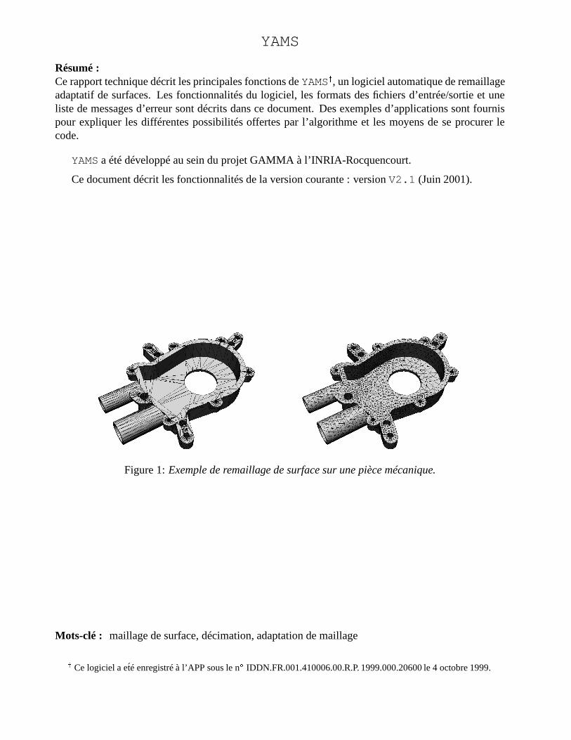
Figure 1: Exemple de remaillage de surface sur une pièce mécanique.
Mots-clé : maillage de surface, décimation, adaptation de maillage
�Ce logiciel a eté enregistré à l’APP sous le n
�
IDDN.FR.001.410006.00.R.P. 1999.000.20600 le 4 octobre 1999.

YAMS : a fully automatic surface remeshing tool 3
Contents
1 Surface remeshing procedure 51.1 Context . . . . . . . . . . . . . . . . . . . . . . . . . . . . . . . . . . . . . . . . . 51.2 Yams overview . . . . . . . . . . . . . . . . . . . . . . . . . . . . . . . . . . . . . 5
2 Input data 62.1 Geometry description . . . . . . . . . . . . . . . . . . . . . . . . . . . . . . . . . . 62.2 Metric specification . . . . . . . . . . . . . . . . . . . . . . . . . . . . . . . . . . . 62.3 Software integration . . . . . . . . . . . . . . . . . . . . . . . . . . . . . . . . . . . 6
3 Output and Errors 73.1 Output files . . . . . . . . . . . . . . . . . . . . . . . . . . . . . . . . . . . . . . . 73.2 Error messages . . . . . . . . . . . . . . . . . . . . . . . . . . . . . . . . . . . . . 7
4 Technical information 84.1 Language, platforms . . . . . . . . . . . . . . . . . . . . . . . . . . . . . . . . . . 84.2 Memory requirement . . . . . . . . . . . . . . . . . . . . . . . . . . . . . . . . . . 84.3 CPU time estimation . . . . . . . . . . . . . . . . . . . . . . . . . . . . . . . . . . 84.4 Distribution . . . . . . . . . . . . . . . . . . . . . . . . . . . . . . . . . . . . . . . 8
5 How to use YAMS 105.1 Flowchart of the algorithm . . . . . . . . . . . . . . . . . . . . . . . . . . . . . . . 105.2 Command line and options . . . . . . . . . . . . . . . . . . . . . . . . . . . . . . . 10
5.2.1 Command line . . . . . . . . . . . . . . . . . . . . . . . . . . . . . . . . . 105.2.2 Other options . . . . . . . . . . . . . . . . . . . . . . . . . . . . . . . . . . 11
5.3 Control parameters . . . . . . . . . . . . . . . . . . . . . . . . . . . . . . . . . . . 115.4 Physical attributes . . . . . . . . . . . . . . . . . . . . . . . . . . . . . . . . . . . . 12
6 Application examples 136.1 Surface simplification . . . . . . . . . . . . . . . . . . . . . . . . . . . . . . . . . . 13
6.1.1 High-quality decimation . . . . . . . . . . . . . . . . . . . . . . . . . . . . 136.1.2 Geometry-driven decimation . . . . . . . . . . . . . . . . . . . . . . . . . . 156.1.3 Application : creation of hierarchical meshes . . . . . . . . . . . . . . . . . 17
6.2 Surface mesh enrichment . . . . . . . . . . . . . . . . . . . . . . . . . . . . . . . . 186.2.1 High-quality geometric surface meshes . . . . . . . . . . . . . . . . . . . . 186.2.2 Geometric surface meshes . . . . . . . . . . . . . . . . . . . . . . . . . . . 196.2.3 Mesh gradation control . . . . . . . . . . . . . . . . . . . . . . . . . . . . . 19
6.3 Surface mesh optimization . . . . . . . . . . . . . . . . . . . . . . . . . . . . . . . 216.3.1 Mesh quality improvement . . . . . . . . . . . . . . . . . . . . . . . . . . . 216.3.2 Surface approximation improvement . . . . . . . . . . . . . . . . . . . . . . 21
6.4 Mesh adaptation . . . . . . . . . . . . . . . . . . . . . . . . . . . . . . . . . . . . . 236.5 2D applications . . . . . . . . . . . . . . . . . . . . . . . . . . . . . . . . . . . . . 25
7 Limitations 267.1 Defining the surface geometry . . . . . . . . . . . . . . . . . . . . . . . . . . . . . 267.2 CAD repair tool . . . . . . . . . . . . . . . . . . . . . . . . . . . . . . . . . . . . . 277.3 About corners and ridges . . . . . . . . . . . . . . . . . . . . . . . . . . . . . . . . 27
RT n˚0252
4 Pascal J. FREY
8 Appendix 288.1 List of error messages . . . . . . . . . . . . . . . . . . . . . . . . . . . . . . . . . . 288.2 Isotropic remeshing . . . . . . . . . . . . . . . . . . . . . . . . . . . . . . . . . . . 30
8.2.1 Shape quality . . . . . . . . . . . . . . . . . . . . . . . . . . . . . . . . . . 308.2.2 Size quality . . . . . . . . . . . . . . . . . . . . . . . . . . . . . . . . . . . 308.2.3 Geometric support . . . . . . . . . . . . . . . . . . . . . . . . . . . . . . . 30
8.3 File formats . . . . . . . . . . . . . . . . . . . . . . . . . . . . . . . . . . . . . . . 318.4 The mesh format . . . . . . . . . . . . . . . . . . . . . . . . . . . . . . . . . . . . 31
8.4.1 Example . . . . . . . . . . . . . . . . . . . . . . . . . . . . . . . . . . . . 328.5 The msh2 format . . . . . . . . . . . . . . . . . . . . . . . . . . . . . . . . . . . . 338.6 the bb format . . . . . . . . . . . . . . . . . . . . . . . . . . . . . . . . . . . . . . 338.7 List of FAQ’s . . . . . . . . . . . . . . . . . . . . . . . . . . . . . . . . . . . . . . 34
References 36
INRIA
YAMS : a fully automatic surface remeshing tool 5
1 Surface remeshing procedure
1.1 Context
Usually, a surface remeshing algorithm is a procedure to transform an arbitrary triangulation (even-tually containing ill-shaped triangles) into a high-quality mesh. This procedure is especially useful togenerate surface meshes in view of numerical simulations or for high-end visualization purposes. Itcan also be used to reduce the amount of data required to represent a complex 3D model. In all cases,the resulting mesh should correspond to a good and accurate (piecewise linear) surface approxima-tion with a reasonable number of elements. Hence, the element size is locally related to the surfacecurvature. In this respect, such a mesh can be qualified as "nearly optimal".
1.2 Yams overview
YAMS is a fully automatic adaptive surface remeshing tool that takes any arbitrary surface triangula-tion and produces an adapted (curvature-based) surface mesh. The remeshing procedure is governedby the geometric surface properties (a geometric size map that relates the element size to the local cur-vature is defined) as well as by a metric map (for instance provided by an a posteriori error estimate),both being defined at the vertices of the input mesh. This scalar map1 provides a suitable element sizeat each mesh vertex to locally discretize the surface accurately. This size map is sufficient to controlthe mesh density and the mesh gradation as well as the element shape quality.
The initial surface description can be any triangulation, for instance supplied by a CAD-CAMpackage or any surface reconstruction algorithm. The input data needs to be orientable and must becomposed of triangles and/or quadrilaterals only. Non-manifold models are handled.
Remark 1.1 In addition to these requirements, additional entities and information can be suppliedto help remeshing the surface (constrained entities, corners, ridges, normals, etc.).
The algorithm proceeds in three steps. At first, the surface is analyzed and its intrinsic propertiesare computed based on the actual discrete representation. This results in the construction of the geo-metric size map. Then, the triangulation is processed and modified according to the size prescription.To this end, topological and geometrical operations are performed to achieve a mesh in which the ele-ment size and the element shape quality are controlled. Finally, a local optimization stage is carriedout to improve the element shape quality.
YAMS also produces diagnostics about the correctness of the surface (regarding its orientation)and various histograms (regarding the quality of the approximation).
1It is a scalar map if the mesh is to be isotropic.
RT n˚0252
6 Pascal J. FREY
2 Input data
The geometry of the surface is described using a simple mesh format. The specification of a metricmap in the context of mesh adaptatation is also described hereafter.
2.1 Geometry description
The surface geometry is described preferably using the mesh file format. (see Appendix for the com-plete description of this format). For compatibility purposes the "old" msh2 format is also supportedin this release. Notice that if quads are supplied, they are automatically converted to triangles.
The mesh format allows to precisely describe the surface features. For instance, corners, ridges,normals can be supplied in this file format to provide more acurate information to the remeshingprocedure. This is the only definition of the surface that the program will know as there is no linkwith a CAD modelling system.
� The mesh format.This format is composed of a single (ASCII or binary) file, xxx.mesh or xxx.meshb. Thisfile contains all the information needed to describe entirely the surface mesh and the underlyinggeometry. It is organized as a series of fields, identified by keywords. In addition to the vertexcoordinates and the list of faces, it allows one to specify additional information such as corners,edges, ridges, required entities (that must be preserved in the final mesh), etc.
� The msh2 format.This very crude format is composed of two ASCII files, xxx.points and xxx.faces des-cribing the geometry (vertex coordinates) and the topology (list of elements) of the surfacemesh, respectively.
2.2 Metric specification
A user supplied size map can be described as a single data file, xxx.bb, containing scalar values(i.e., a sizing information) which are associated with the vertices (or with the elements) of the givensurface mesh. By default, when reading an input file (test.mesh, for instance), the program willlook to see if there is any size specification attached to this file (test.bb). In this case, the user-specified metric will be combined with the intrinsic geometric metric in order to preserve the elementsize in highly curved region while modifying the standard size by the one supplied by the user in theplanar regions.
2.3 Software integration
If YAMS is integrated in a software package, only the input and output routines need to be modified,for efficiency and compatibility purposes. In this context, no more than 4 routines need to be modifiedand adapted to support the user file formats.
INRIA
YAMS : a fully automatic surface remeshing tool 7
3 Output and Errors
3.1 Output files
Usually, a single output file is produced at completion, representing the resulting mesh. This file,xxx.meshb, is written in the binary mesh format by default. It contains the geometry and topologyof the piecewise linear approximation (i.e., the vertex coordinates and triangles) as well as additionaldata relative to the specific features : the corners and ridges, for instance. A more complete file canalso be exported in mesh format containing normals, tangents, etc, if desired.
If specified, the current size map can be written in a xxx.bb file (similar to that used as inputfile).
Notice that the output files are fully compatible with the input files, thus making it easy to useYAMS as an optimizer (the output files becoming the input files when running the code again).
3.2 Error messages
At completion of the remeshing procedure, two cases can be encountered :
� A mesh file has been created, hence meaning that the resulting mesh is valid. However, thisdoes not necessarily means that the mesh is a very accurate surface approximation, as this resultis strongly related to the parameter specification (see Section 5.2).
� No output file has been produced : either the data are incorrect (or missing), or the algorithmdetected a blocking error and stopped, writing an error code (see below).The program may stop for various reasons, for instance :
– the input file (in the msh2 format) contains faces other than triangles or quadrilaterals,
– the allocated memory size is not sufficient. The solution is then to increase the memorysize : option [-m MegaBytes],
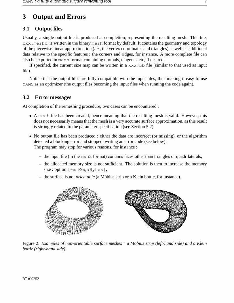
– the surface is not orientable (a Möbius strip or a Klein bottle, for instance).
Figure 2: Examples of non-orientable surface meshes : a Möbius strip (left-hand side) and a Kleinbottle (right-hand side).
RT n˚0252

8 Pascal J. FREY
4 Technical information
4.1 Language, platforms
From the beginning, the program has been entirely written in C (ANSI). The current version consistsof about 17,000 lines of optimized source code. Hence, the code is very portable and has beensuccessfully compiled and tested on all major computer architectures (i.e., HP, Sun, SGI, IBM, Intel-based PC, etc.) and operating systems (Unix/Linux, WindowsNT, Mac OS).
4.2 Memory requirement
The program requires roughly about�����
bytes per vertex thus making it possible to estimate a priorithe required memory size to complete a job. As an example of memory space needed, a mesh of�����������
points ( ����������� triangles) requires 182 MegaBytes (i.e., 351 bytes per point). Conversely,a workstation having
� � MegaBytes of memory can handle a mesh of about����������������
points.The memory is dynamically allocated at the data file reading stage, also, it obeys the following
simple rule. If the user choses to only simplify or optimize the given mesh, then the memory allocatedis strictly the memory required to store the input mesh. However if the user selects a mesh enrichmentoption, the memory is automatically set up to 1.5 times the initial size (i.e., required to store theinput mesh). This simple bound prevents any memory overflow because of small artifacts in theinitial surface discretization. If during the execution, the memory allocation becomes insufficient, thefollowing error message is issued :
ERR 4002, proc, UNABLE TO CREATE NEW TRIANGLE
In such a case, the user can either decide to run the program again and specify the total amountof memory using the [-m MegaBytes] option (see below) or chose to change the minimal sizeprescribed in the configuration file.
4.3 CPU time estimation
The CPU time required to obtain the final mesh (including the I/O) is obviously related to the com-plexity of the surface, as well as to the parameters and options specified. Nevertheless, one canreasonably expect (see table in section 6) :
� a few seconds to simplify a mesh of several thousands of elements and
� a few minutes to enrich a mesh of several hundreds of thousands of elements.
4.4 Distribution
An evaluation copy of YAMS software for a limited period of time can be obtained by contacting theauthors at INRIA :
Pascal FREYINRIA, Domaine de VoluceauBP 105, 78153 Le Chesnay cedex, FranceEmail: [email protected]://www-rocq.inria.fr/gamma/yams/yams.html
INRIA

YAMS : a fully automatic surface remeshing tool 9
or by contacting Simulog, the distributor of YAMS worldwide :
SIMULOG1, rue James Joule78286 GUYANCOURT cedex, FranceFax number: (33) 1 3012 2727 (attention Mark Loriot)Email: [email protected]://www.simulog.fr,
section Compos. maillages/Meshing Software Components
Simulog provides State-of-the-Art meshing software components that ensure software developers tosuccessfully create their CAD/CAE applications. In this respect, Simulog can deliver source code forintegration purposes or binary files (on various platforms) of the current version of YAMS.
RT n˚0252

10 Pascal J. FREY
5 How to use YAMS
In this section, indications about the general scheme of the algorithm are provided as well as somehints to achieve specific results.
5.1 Flowchart of the algorithm
As indicated above, the mesh algorithm is based on local topological and geometrical modifications(see reference [4] for more details). The general scheme of the method includes the following steps :
� reading the input file(s), and the metric file (if any),
� surface analysis (orientation, normal computation, ridge and corners identification, etc.),
� iterative local modifications using geometrical operators (node repositioning, vertex insertion/deletion)and topological operators (edge flipping),
� mesh optimization (by relocating the vertices or using topological operators to improve theelement aspect ratio while conforming to the sizing map),
� writing the output file(s).
5.2 Command line and options
YAMS is invoked via a single command line. At this level, only a few options can be specified.
5.2.1 Command line
The usual way of starting YAMS is to type in the following line :
yams [-O n] [InputFile].
Also, typing : yams -h will give the meaning of all the various options.
By default, the name of the output file corresponds to the basename of the input file followed bythe extension .d (for example, test.d.meshb if the input is test.meshb). The user can supplyany file name for the output file.
The user needs to specify which treatment has to be carried out on the input data : i.e., simplifica-tion, enrichment, optimization, adaptation or smoothing. The meshing options are specify using thecommand : yams -O n, where the parameter n means :
INRIA

YAMS : a fully automatic surface remeshing tool 11
0 optimization only (quality improvement). The number of nodes remains identicalto that of the initial surface triangulation.
1 high-quality surface remeshing. The final mesh is suitable for numerical simulations(nearly equilateral triangles, mesh density related to the local curvature).
2 geometric surface remeshing (Hausdorff based). The distance between the finalmesh and the original one is bounded by a threshold value. The triangles are slightlyanisotropic.
3 pattern-based geometric surface enrichment. Nodes are added for geometric pur-poses (i.e., improving the geometric approximation).
9 improve surface approximation. This is useful for processing "Marching-Cubes"like meshes (e.g., to remove staircase effects).
Notice that negative values of n for options 1 and 2 can be specified, thus indicating that the meshneeds only to be simplified (this option accelerates the global processing of the mesh). New nodesare created on an internally build
���support to improve the quality of the geometric approximation.
5.2.2 Other options
Other options can also be specified on the command line :-v [n] Verbosity level (to get more information during the process),-b Save .bb metric file,-c [n] Save connected component n only,-e Save extended information in output file (normals, tangents, etc.),-f Save formatted (ascii) output file,-m [n] Set the memory size to n MegaBytes,-nm Create point on straight edge (no mapping on geometric support),-no Do not write output file,-ns Disable node smoothing during the optimization stage,-vrml Save VRML (level 1) file.
Remark 5.1 By default, only the option -O [n] and the name of the data file need to be specified.
5.3 Control parameters
In addition to the previous options, a few control parameters are required to properly characterize thedesired surface approximation2. These parameters are stored in a simple text file, named xxx.yams(associated with xxx.mesh file) or DEFAULT.yams. The file structure is organized as a series offields, composed of a keyword and a scalar value.
Remark 5.2 For the sake of simplicity, all parameters have been assigned reasonable default values,thus making it possible to run YAMS without creating such a file.
Parameters that can be specified are as follows (notice that all keywords are not case sensitive) :
� Absoluteindicates that the tolerance and size parameters are specified in model unit. Default is to consi-der relative values (e.g. in 1/1000 of the bounding box size).
2This make surface remeshing more tedious to control than volume meshing !
RT n˚0252

12 Pascal J. FREY
� Tolerance,�
(Float)used to specify the maximum allowable chordal deviation
�.
Default value is 1/1000 of the bounding box size (or model units).
� GeomApp, � (Float)used to control the surface smoothness (bound the maximal deviation of the mesh edges fromthe tangent plane at mesh vertices).Range : 0.001 to 0.1, default value : 0.01.
� Ridge, � (Float)allows to specify the angular value for the detection of ridges and corners (i.e., the measure ofthe angle between the normals of adjacent faces or edges).The default value is
� �degrees.
� Gradation, ������ (Float)indicates the rate of the size variation between neighboring elements.Values : -1 if no gradation is desired, range : 1. to 100, default : 1.3.
� MinSize, ��� �� (Float) and MaxSize, ������ (Float)allow to prescribe a minimal (resp. maximal) element size.Default ��� �� is 5/1000 of the bounding box size (or model units). No default value for ������ .
� NbIter, � (Integer)used to prescribe the number of smoothing iterations when invoking the option -O 9. Thedefault value is set to 50.
5.4 Physical attributes
Inherently, the surface remeshing algorithm preserves the physical attributes specified in the inputfile (vertex, edge and face references). However, as can be easily understood, the numbering of thevertices is affected by the algorithm. However, with option -O 0, it may be possible to preservevertex numbers (although not the triangle numbering).
The different surface connected components are automatically identified based on the ridge detec-tion. In the case where several components have been identified, the algorithm can retain only one ofthem (using the option [-c n] in the command line).
INRIA

YAMS : a fully automatic surface remeshing tool 13
6 Application examples
This aim of this large section is to emphasize the various features of the software package YAMS.To this end, we will illustrate the two possible approaches for surface simplification. Then, we willfocuss on surface enrichment and illustrate how to obtain a high-quality surface mesh for numericalsimulations. Afterwards, surface mesh optimization will be briefly discussed and finally, examples ofmesh adaptation will be provided to show the efficiency of the algorithm in the context of numericalsimulations based on finite element/volume methods.
6.1 Surface simplification
One of the most attractive feature of YAMS is the possibility of reducing the number of mesh entitieswhile controlling :
i) the quality of the geometric approximation,
ii) the surface properties (curvatures, ridges, etc.) and
iii) the global mesh quality.
Numerous fields of applications are concerned with this feature, including computer graphics, carto-graphy, virtual reality, numerical simulation, etc.
Given a surface triangulation, two options of mesh simplification are proposed in the softwarepackage, allowing to obtain :
� high-quality (finite element) surface meshes (meshes that are primarily intended for numericalsimulations) or
� geometric surface meshes (suitable for visualization purposes in which element shape qualitycontrol is less crucial).
6.1.1 High-quality decimation
This possibility corresponds to the option -O -1 of the command line. The original surface trian-gulation is simplified according to the geometric size map computed internally. Typically, this optiontriggers the construction of a high-quality geometric mesh (i.e., a good geometric approximation ofthe surface). In this kind of mesh, the element sizes are directly related to the local curvature. This op-tion involves three parameters : the tolerance Tolerance, the geometric approximation GeomAppand the mesh gradation Gradation.
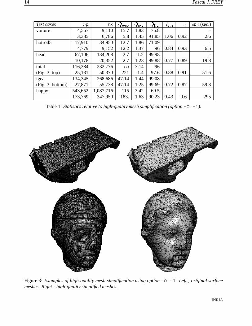
Table 1 reports some results for this type of mesh simplification procedure. In this table, � � and��� represent the number of points and triangles, � � ��� and � ����� represent respectively the worst andaverage element shape quality (see Appendix), ��� ��� is the percentage of elements having a qualitybetter than 2, ����� and � represent the average edge lengths and the efficiency coefficient, � ��� denotesthe CPU time (on a 550 Mhz HP 9000 workstation). In this table, the first line of each exampleindicates the initial values and the second line the final results. All examples have been computedusing the default parameter values (i.e., no .yams file used).
Notice that the average quality is usually very close to 1 and the number of elements having aquality better than 2 is above � ��� , although there is no guarantee (nor a numerical bound) on the finalmesh quality. In some cases, a few badly-shaped triangles may remain because of some geometricalconstraint (e.g., a skiny triangle located between two ridges).RT n˚0252
14 Pascal J. FREY
Test cases � � � � � � � � � ����� � � ��� ����� � � ��� (sec.)voiture 4,557 9,110 15.7 1.83 75.8 -
3,385 6,786 5.8 1.45 91.85 1.06 0.92 2.6hotrod5 17,910 34,950 12.7 1.86 71.09 -
4,779 9,152 12.2 1.37 96 0.84 0.93 6.5head 67,106 134,208 2.7 1.2 99.98 -
10,178 20,352 2.7 1.23 99.88 0.77 0.89 19.8total 116,384 232,776 � 3.14 96 -(Fig. 3, top) 25,181 50,370 221 1.4 97.6 0.88 0.91 51.6igea 134,345 268,686 47.14 1.44 99.08 -(Fig. 3, bottom) 27,871 55,738 47.14 1.25 99.69 0.72 0.87 59.8happy 543,652 1,087,716 115 3.42 69.5 -
173,769 347,950 183. 1.63 90.23 0.43 0.6 295
Table 1: Statistics relative to high-quality mesh simplification (option -O -1).
Figure 3: Examples of high-quality mesh simplification using option -O -1. Left ; original surfacemeshes. Right : high-quality simplified meshes.
INRIA

YAMS : a fully automatic surface remeshing tool 15
6.1.2 Geometry-driven decimation
This feature corresponds to option -O -2 of the command line options. It allows the user to generatea surface approximation corresponding to a bounded deviation from the original surface triangulation.The tolerance value can be seen as a protective envelope surrounding the original triangulation. In thisoption, the Hausdorff between the two surfaces is computed to make sure that the surface deviationremains bounded below the threshold value. Usually, the resulting meshes present anisotropic fea-tures, the elements being stretched along the main directions of curvature. Hence, resulting meshesare mainly intended for visualization purposes, where the geometric accuracy is needed while theelement shape quality is less important. Specifying a MaxSize allows the user to bound the naturalstretching of the elements.
Table 2 reports some results for this mesh simplification procedure ( � ����� represents the worstmesh quality, � � � denotes the CPU time on a HP 9000 workstation). In this table, the first (resp.second) line of each example corresponds to the initial (resp. final) meshes.
Test cases � � ��� � ����� � ��� (sec.)pda06 (Fig. 4) 6,768 13,540 68.2 -
717 1,438 68.2 0.7corvette5 11,155 21,750 52.3 -
1,472 2,735 51.9 1.4isis (Fig. 5) 45,749 91,494 173 -
5,891 11,778 173 7.6r96012-250 126,157 250,413 2,942 -
20,247 38,828 54 29igea 134,345 268,686 47.14 -
19,512 39,020 47.14 22.6total88 876,487 1,812,094 5.98 -
12,133 33,002 41.9 76
Table 2: Statistics relative to geometry-driven mesh simplification (option -O -2).
Figure 4: Example of geometry-driven mesh simplification using option -O -2. Left : original mesh.Right : simplified surface mesh.
RT n˚0252
16 Pascal J. FREY
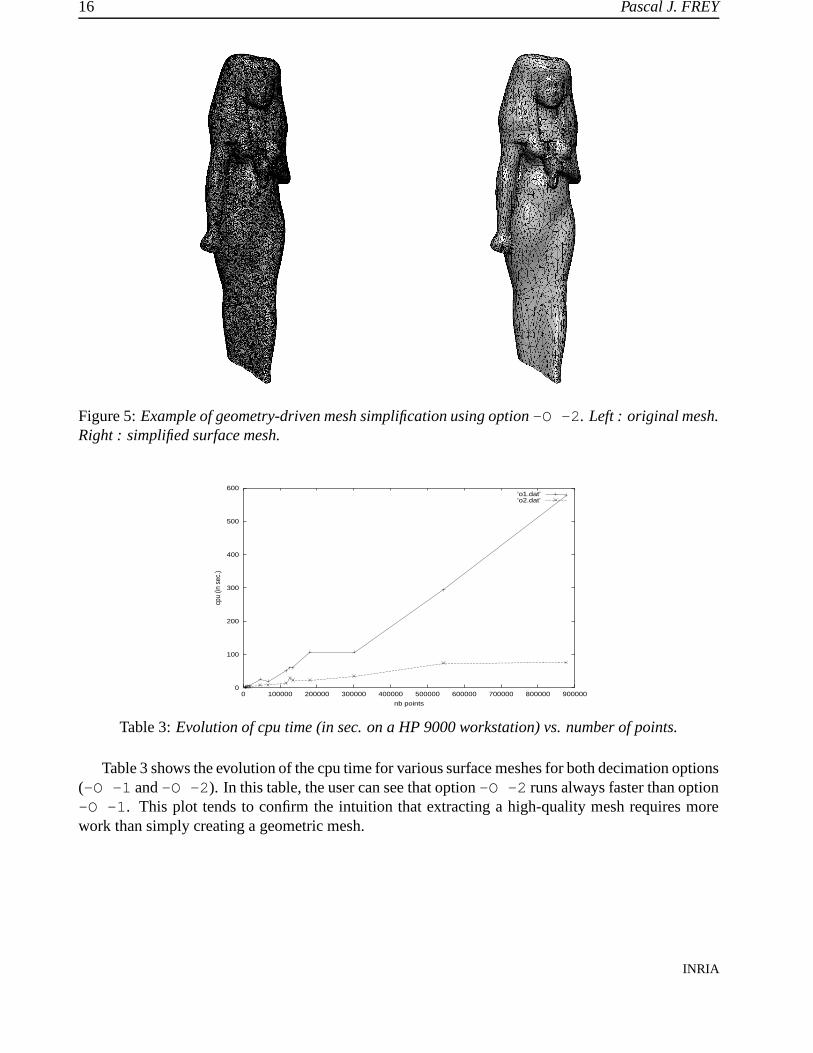
Figure 5: Example of geometry-driven mesh simplification using option -O -2. Left : original mesh.Right : simplified surface mesh.
0
100
200
300
400
500
600
0 100000 200000 300000 400000 500000 600000 700000 800000 900000
cpu
(in s
ec.)
nb points
’o1.dat’’o2.dat’
Table 3: Evolution of cpu time (in sec. on a HP 9000 workstation) vs. number of points.
Table 3 shows the evolution of the cpu time for various surface meshes for both decimation options(-O -1 and -O -2). In this table, the user can see that option -O -2 runs always faster than option-O -1. This plot tends to confirm the intuition that extracting a high-quality mesh requires morework than simply creating a geometric mesh.
INRIA

YAMS : a fully automatic surface remeshing tool 17
6.1.3 Application : creation of hierarchical meshes
In some cases, for instance for visualization purposes, it may be desirable to create various occurencesof the same model at different level of detail. This is possible using YAMS with options -O -1or -O -2 increasing the value of the Tolerance parameter (see example Figure 6). It is alsopossible to generate a surface mesh at any level that is composed of a subset of the nodes of the initialtriangulation. In this case, the user has to specify -ns on the command line to prevent the nodesto be relocated during the simplification stage. The initial mesh (not displayed in Figure 6) contains�����������
vertices.
h1 h2 h3 h4
Figure 6: Geometric mesh simplification applied to the construction of hierarchical meshes. Themeshes contains
� ����� vertices, ��������� vertices,������ � � vertices and
����������vertices, respecti-
vely (data courtesy Stanford University, CG dept.).
h1 h2 h1 h3 h1 h4
Figure 7: Use of hierarchical meshes for visualization purposes.
RT n˚0252

18 Pascal J. FREY
6.2 Surface mesh enrichment
If the given surface triangulation is a poor approximation of the underlying surface geometry orif it does not have enough nodes or if the mesh elements are not well shaped, then surface meshenrichment becomes necessary. In this contexte, YAMS offers the possibility of enriching a givenmesh, i.e. of adding vertices on the surface. The software being not directly related to any CADsystem, a procedure has to be defined to answer a query like : "given a point find the closest pointonto the surface". To this end, a geometric support (
� �continuous) is defined internally that will be
used to locate points onto the surface and to answer queries, hence emulating the behavior of a simplegeometric modeller. This geometric support represents the analytical definition of the underlyinggeometry [6, 7].
Again, two options are concerned with this feature, that allow to define :
� high-quality surface meshes (for numerical simulations),
� geometric surface meshes (without element shape quality control).
6.2.1 High-quality geometric surface meshes
This feature corresponds to option -O 1 of the command line. As for the corresponding decimationoption, an internal curvature-based metric is constructed that prescribe, at each mesh vertex, thedesired element size, depending on the Tolerance, GeomApp and Gradation values specified.
Table 4 reports statistics about the mesh enrichment procedure for various surface meshes. In thistable, � � and � � represent the number of points and triangles, � � ��� and � ����� represent respectivelythe worst and average element shape quality, � � ��� is the percentage of elements having a qualitybetter than 2, ����� and � represent the average edge lengths and the efficiency coefficient, � ��� denotesthe CPU time (on a HP 9000 workstation). In this table, the first line of each example indicates theinitial values and the second line the final results.
Test cases � � ��� � ����� � ����� � � ��� � ��� ����� � � ��� (sec.)coupelle 329 540 17.4 2.1 74.8 -
1,555 2,778 10.1 1.5 84. 0.91 0.94 1.7pump 1,646 3,312 45.7 5.2 32.5 -(Fig. 1) 7,101 14,222 11.7 1.4 88.8 0.92 0.94 11thepart 994 1,992 65 7.1 18.4 -(Fig. 8, top) 7,377 14,758 13.6 1.3 97.7 0.95 0.95 16.2b1 3,013 6,062 4.3 1.4 89.6 -
18,535 37,106 8.9 1.4 89.4 0.52 0.7 41.1airbus 4,878 9,752 8.5 1.1 99.1 -
17,608 35,212 16.4 1.4 96.7 0.8 0.89 29.modelb 17,445 34,930 9.5 1.4 98.39 -
21,500 43,040 14 1.3 94.76 0.9 0.93 41
Table 4: Statistics relative to high-quality mesh enrichment (option -O 1).
INRIA

YAMS : a fully automatic surface remeshing tool 19
Figure 8: Example of high-quality surface mesh enrichment. Left : original surface triangulation.Right : high-quality mesh.
Figure 9: Example of high-quality surface mesh enrichment. Left : original surface triangulationwith minimal number of vertices. Right : high-quality mesh.
6.2.2 Geometric surface meshes
This feature correspond to option -O 2 of the command line. As for the corresponding decimationoption, the resulting surface meshes are slightly anisotropic. Here also, the meshes are primarilyintended for visualization purposes, when the element shape quality is less important than preservingthe geometric accuracy of the surface discretization.
Remark 6.1 In this version, the option -O 3 of the command line allows the user to stop after thepoint insertion stage (without removing extra vertices). This makes possible the creation of geome-trically accurate meshes that may be considered as geometrical support (i.e., the mesh stands for thegeometry definition, cf. Figure 10).
6.2.3 Mesh gradation control
The element shape quality is of utmost importance in numerical simulations as it may impact theaccuracy of the numerical solutions. Usually, the quality of an element can be controlled by thesurface remeshing program. However, the shape quality is also related to the local mesh densityand the size distribution function [2]. YAMS allows the user to control the rate of the size variationRT n˚0252
20 Pascal J. FREY
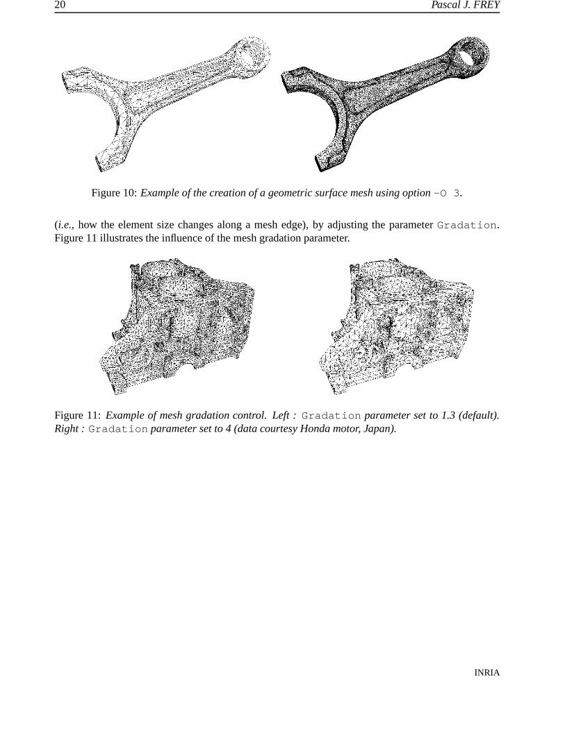
Figure 10: Example of the creation of a geometric surface mesh using option -O 3.
(i.e., how the element size changes along a mesh edge), by adjusting the parameter Gradation.Figure 11 illustrates the influence of the mesh gradation parameter.
Figure 11: Example of mesh gradation control. Left : Gradation parameter set to 1.3 (default).Right : Gradation parameter set to 4 (data courtesy Honda motor, Japan).
INRIA

YAMS : a fully automatic surface remeshing tool 21
6.3 Surface mesh optimization
As the accuracy of the numerical solutions are related to the mesh quality in finite element/volumemethods [3], it may be desirable to improve the mesh quality, while keeping the number of nodesunchanged. This requirement is also of interest as the quality of a surface mesh (defining the boundaryof a volume) affects the quality of a 3D tetrahedral mesh.
In this respect, YAMS allows one to improve the element shape quality of the given surface trian-gulation, while preserving the geometric approximation.
6.3.1 Mesh quality improvement
A straightforward way of optimizing a mesh is to keep the number of mesh vertices constant andsimply make local adjustements (edge flipping, node relocation) so as to improve the element shapequality. This feature corresponds to option -O 0. Figure 12 illustrates the quality improvementprocedure.
Remark 6.2 This option may also be useful to slightly improve the quality of a surface mesh proces-sed by YAMS. It usually leads to remove badly-shaped elements that a previous treatment was unableto delete (as local curvatures are recomputed).
Figure 12: Example of surface mesh optimization. Left : original surface triangulation (data courtesyIFP, Paris). Right : optimized surface mesh.
6.3.2 Surface approximation improvement
The "Marching Cubes" algorithm is one of the most popular surface reconstruction algorithm whendealing with discrete data (for instance, supplied by sensing or scanning devices). However, the majordrawbacks of this algorithm is that :
i) it usually produces too many mesh elements,
ii) the surface approximation is usually very poor (staircase effect).
YAMS provides an easy solution to overcome these problems. Using option -O 9 the code can im-prove the surface approximation (i.e., remove the staircases). Then, the user may choose to simplifythe mesh using options -O -1 or -O -2. Figure 13 illustrates the option -O 9 on a biomedicaldata.RT n˚0252

22 Pascal J. FREY
Figure 13: Example of surface approximation improvement. Top left : original mesh (���� ��� ver-
tices), top right : ’smoothed’ mesh after 100 iterations. Bottom left : after option -O -1 ( � ��� �vertices, 20.1 sec), bottom right : after option -O -2 (
���������vertices, 9.7 sec.).
INRIA

YAMS : a fully automatic surface remeshing tool 23
6.4 Mesh adaptation
In the context of numerical simulations based on finite element/volumes, it is often desirable to controlthe mesh density more precisely than just taking the surface geometry into account. For instance, inCFD, it is required to have small elements in shock-wave or boundary layer regions, even if thegeometry is locally planar. The mesh density is then prescribed using a user-specified size map (forinstance constructed from an a posteriori error estimate).
In this regard, YAMS can also be used as a mesh adaptation tool, to adapt the mesh to the problemto solve (i.e., to a specific size map). To this end, the algorithm will combine the geometric metric(computed internally) with the user supplied metric. Hence, the resulting mesh will have a mesh den-sity related to the local curvature of the surface as well as to the user prescribed size map. This featurecan be achieved using the option -O 1 (the one used to create high-quality meshes) in combinationwith the reading of a xxx.bb file to feed the algorithm with a required size per vertex.
Figure 14 shows an example of mesh adaptation on a CFD example (transonic flow over a ONERAM6 wing, Mach 0.84, angle of attack 3.06).
RT n˚0252

24 Pascal J. FREY
Figure 14: ONERA M6 wing : adapted meshes and iso-mach lines associated to iterations 1 (��� ���� �
vertices), 4 ( � ���� � vertices) and 7 ( ����������� vertices).
INRIA

YAMS : a fully automatic surface remeshing tool 25
6.5 2D applications
Although YAMS is inherently a surface remeshing software, it can also process 2D (triangular) meshes.In this case, 2D triangulations are considered as planar surfaces. All available options (except option-O 9) apply to planar meshes as well as to surface meshes. Figures 15 and 16 illustrate the optimi-zation and adaptation of planar meshes.
Figure 15: Example of planar surface remeshing.
Figure 16: Example of planar surface adaptation in CFD. Left : original (�����
vertices) and finaladapted (
��� ���vertices) meshes. Right : the corresponding isodensity values.
RT n˚0252

26 Pascal J. FREY
7 Limitations
This section is intended for making precise several assumptions about surface meshing. It consists ofa series of answerss about surface remeshing questions the users may be faced with. It is also intendedfor precising the limits of the software (i.e., the things it cannot do)3.
7.1 Defining the surface geometry
As already mentioned, YAMS is not related to any CAD modelling system. Therefore, the surfacegeometry is only guessed from the given surface triangulation. To be able to remesh this surface andobtain a high-quality surface mesh, the user must take care of supplying a triangulation that is alreadya good (if not accurate) piecewise linear approximation of the model geometry. This may not bealways possible, especially when dealing with scanned data (see FAQ in Appendix).
Notice that YAMS keeps the topology of the mesh unchanged, if the initial triangulation is notconformal, the resulting mesh will also not be.
Usually, CAD systems are able (i.e., have an option) to output an initial surface triangulationthat contains a large numbers of equally spaced nodes thus representing a good description of theunderlying surface. In such cases, the task is made easy for YAMS. Indeed, mesh simplification willbe more likely to give the desired result.
However, recent experiences have shown that CAD systems now export, presumably optimal,triangulations with a minimal amount of nodes (see Figure 17, for instance). If these triangulationsmay be used for graphic purposes, they are not, by all means, geometric meshes (see Figure 17, right-hand side, for a local enlargement showing the problem). The user must be convinced that YAMScannot do a good job on such surfaces, because the geometry of the surface is not well captured (thelocal curvature is violated, the geometric tolerance is varying a lot, etc.). Consequently, YAMS isprobably not the right tool to be applied on such triangulations.
Figure 17: Example of ’pseudo-geometric’ surface triangulation. Right : enlargement on a problemarea where the two directions of curvature are not well captured.
3Some of these questions could have figured in the FAQ list.
INRIA
YAMS : a fully automatic surface remeshing tool 27
7.2 CAD repair tool
Be conscious that YAMS is not a CAD repair tool. Indeed, the software will preserve the mesh topo-logy and geometry defined by the initial surface triangulation. In particular, if the given triangulationis non-manifold, the resulting mesh will also be non-manifold (although option -c n can sometimesget rid of the problem by saving a specific connected component). Similarly, YAMS will preservethe mesh conformity and will not fill the holes and gap between elements. If the surface is self-intersecting, this characteristic will also remain in the final mesh.
7.3 About corners and ridges
Usually, corners and ridges are defined based on the Ridge parameter in the .yams file. Ridges aredefined when the dihedral angle between 2 faces exceeds the prescribed limit. Corners are definedwhen 3 incident ridges meet at a vertex or if 2 ridges form a small angle.
The limit between 2 sub-domains (neighboring triangles with different references) defines a curvetraced onto the surface. This curve will be remeshed according to the prescribed tolerance value, thusinducing some more constraint in the remshing process.
RT n˚0252

28 Pascal J. FREY
8 Appendix
This section will provide information about the error messages, file formats, shape and size qualityfunctions used in YAMS software. At the end of this section a list of Frequently Asked Questions willhelp the user to better understand the main concepts and control parameters of YAMS.
8.1 List of error messages
Warnings, errors and possible cause of failure are identified and listed hereafter. Usually the syntaxof error messages is the following :ERR xxxx, proc, MESSAGE, list,where xxxx stands for the error number, proc is the name of the procedure in which the error wasdetected, MESSAGE is the error diagnostic and list is a (facultative) list of arguments related to thiserror (e.g. a list of mesh entities). The first digit of the error number indicates the stage of the processin which the error occured :
0 the process was in the preliminary stage (reading input files),1 analysis stage : surface orientation, normals and tangents computation, etc.,4 surface remeshing problems,9 runtime or system-dependent errors : cancelled job, hardware problem, etc.
The list of diagnostics is as follows :
[L0 ] Level 0 : input data related errors.These errors are mainly related to incorrect data file or memory allocation problems.
ERR MESSAGE DIAGNOSTIC / CORRECTION0000 WRONG DATA TYPE,
�. Incorrect data file (wrong dimension or vertex
field missing).0001 NO INPUT DATA No element found in the input mesh.0002 NOT ENOUGH MEMORY Not enough memory space to store the mesh
structure. Solution : use option [-m Me-gaBytes] on the command line to increasemem. size.
0003 WRONG FILE NAME Check spelling.0004 DATA NOT CONSIDERED This data is not processed.0005 UNABLE TO OPEN FILE Unable to open data file. Solution : set the
correct read permissions.0010 NORMAL AT VERTEX DISCAR-
DEDNormal vector discarded (wrong vertex num-ber)
0011 NORMAL AT TRIANGLE VERTEXDISCARDED
Normal vector discarded
0020 FACE DISCARDED Face�
discarded from the triangulation.0021 EDGE(S) IGNORED Set of edges discarded (memory problem).0022 � FACES DISCARDED Number of discarded faces0030-33 MEMORY REALLOC PROBLEM Unable to expand memory space.
(HASH, NORMALS, TANGENTS) Solution : use option [-m n]
INRIA

YAMS : a fully automatic surface remeshing tool 29
[L1 ] Level 1 : Surface analysis and topology errors.These errors are mainly related to topology problems (e.g., orientation, etc.).
ERR MESSAGE DIAGNOSTIC / CORRECTION1001 EDGE PROBLEM
� ����������Edge
� �������, face
discarded.
1010 � ADJACENCY PROBLEM Same face occurs at least twice.1011 ORIENTATION PROBLEM Surface mesh is not orientable.1012 WRONG TOPOLOGY Mesh topology corrupted.1013 EDGE FLIP PROBLEM Unable to update data structure.1014 WRONG EDGE TOPOLOGY Unable to update adjacent faces.1015 EDGE NOT CORRECTLY HASHED Internal data structure corrupted.1020 NO ROOT FOR COMPONENT Unable to correctly identify connected com-
ponent�.
[L4 ] Level 4 : Surface remeshing errors.
ERR MESSAGE DIAGNOSTIC / CORRECTION4000 UNABLE TO CREATE NEW POINT Not enough memory to add new vertex.4001 UNABLE TO CREATE NEW TRI-
ANGLENot enough memory to create new triangle.
4006 POOR SHAPE QUALITY Element
is very badly-shaped.4007 SURFACE TOO SMALL4008 SMALL INRADIUS Badly shaped element.4010 CURVE TANGENT PROBLEM Curve equation not reliable. Solution : use
option -nm to avoid building geometric sup-port.
4011 NORMAL VARIATION New vertex normal differs from old one bymore than 15 deg.
4012 INCONSISTENT BALL OF VERTEX Topology corrupted.
[L8 ] Level 8 : Output errors.
ERR MESSAGE DIAGNOSTIC / CORRECTION8000 UNABLE TO SAVE MESH FILE. Check write permissions8001 UNABLE TO SAVE METRIC FILE.8003 CURRENT MESH NOT SAVED. Because of a previous error
[L9 ] Level 9 : errors related to software problems (floating point exceptions, segmentation fault,job cancelled, etc.). The current mesh will not be saved.
ERR MESSAGE9900 ABNORMAL STOP.9901 FLOATING-POINT EXCEPTION.9902 ILLEGAL INSTRUCTION.9903 SEGMENTATION FAULT.9904 PROGRAM KILLED.
RT n˚0252
30 Pascal J. FREY
8.2 Isotropic remeshing
The aim of the surface remeshing algorithm is to produce high-quality geometric surface meshes. Thismeans that the desired element shape is the (nearly) equilateral triangle. The element size is locallyrelated to the surface curvature as prescribed by the geometric size map. The other requirement isto obtain a valid and accurate piecewise linear approximation of the surface geometry. Therefore,the metric map that is constructed internally is able to take into account both the shape and sizerequirements.
8.2.1 Shape quality
For a triangle, the shape quality function measures the aspect ratio of the element and is defined asfollows :
� ��� � � � �� � �(1)
where �� ��� is the element diameter (i.e., its longest edge), � � is the inradius of triangle � and � isa normalization coefficient chosen so that the quality of the equilateral triangle is equal to 1. Noticethat this function ranges between 1 and � , the optimal value being 1. For a mesh � , a global qualitymeasure is computed as :
��� ��� ���� � � ���8.2.2 Size quality
The length of a mesh edge ��� with respect to the size specification can be computed as :
���� � �� � � � � �� �
��� � � � � (2)
where �� � � � � is the Euclidean distance between � and � and
��� �is a monotonous size variation
function along ��� . Furthermore, an efficiency index can then defined as :
� � �� � �
� � "! � � #� � � � (3)
with � � if %$ and � � '& if %( , � � being the number of mesh edges. A value of � greaterthan 0.93 indicates that the resulting mesh conforms well to the size map.
8.2.3 Geometric support
To improve the accuracy of the piecewise linear approximation of the surface, a geometric support ofclass
� �is locally constructed. It is used to locate a point on the surface when splitting an edge or
moving a node. To some extent, this support emulates some queries of a geometric modeller.
INRIA

YAMS : a fully automatic surface remeshing tool 31
8.3 File formats
As mentioned in the second section, the geometry of the surface is described using a simple meshformat. The mesh format allows to specify surface features such as ridges, corners, normals, etc.
8.4 The mesh format
This format is composed of a single (binary or text) data file. Its structure is organized as a seriesof fields identified by keywords. The blanks, ”newline” or $ CR ( and tabs are considered as itemseparators. A comment line starts with the character # and ends at the end of the line. The commentsare placed exclusively between the fields.
The mesh file must start with the descriptor :
MeshVersionFormatted 1Dimension 3
The other fields supported by YAMS are either required or faculative. The required fields correspondto the geometry (i.e., the coordinates) and to the topology description (i.e., the mesh entities). In thefolowing tables, the term � indicates a vertex number (i.e., the
�����vertex in the vertx list), � is an
edge number,� is a triangle number and � is a quadrilateral number. Notice that the vertices are real
numbers in single precision.
Keyword Card. Syntax RangeVertices � � � � � �� � � � � � � � ���Edges � � � � � � � � � � � � � � �Triangles �
� ��� � � � � � � � � � � � ��� � ��� �Quadrilaterals ��� � � � � � � � � � ��� � � ��� � � � �
Then, follows the description of constrained entities or singularities. In particular, a corner pointCorner is a point where there is a �
�continuity between the edges sharing it (this type of item is
necessary a mesh vertex). By analogy, a Ridge is an edge where there is a �
�continuity between
the adjacent faces. The fields of type Requiredxx make it possible to specify any type of entitythat must be preserved by the meshing algorithm.
Keyword Card. Syntax RangeCorners ��� � � � � � ��� �RequiredVertices � � � � � � � � � � ���Ridges � � � � � � � � � �RequiredEdges � � � � � � � � � � � �RequiredTriangles � �
� � � � � � � � � �
RequiredQuadrilaterals � ��� � � � � � � ��� �As mentioned above, it is also possible to specify normals and tangents to the surface. The nor-
mals (resp. tangents) are given as a list of vectors. The normal at a vertex, keyword NormalAtVer-tices, is specified using the vertex number and the index of the corresponding normal vector. Thenormal at a vertex of a triangle, NormalAtTriangleVertices, corresponds to the combinationof the triangle number, the index of the vertex in the triangle and the index of the normal vector at thisvertex. Similarly for the field corresponding to the keyword NormalAtQuadrilateralVer-tices. The tangent vectors are described in the same way.RT n˚0252
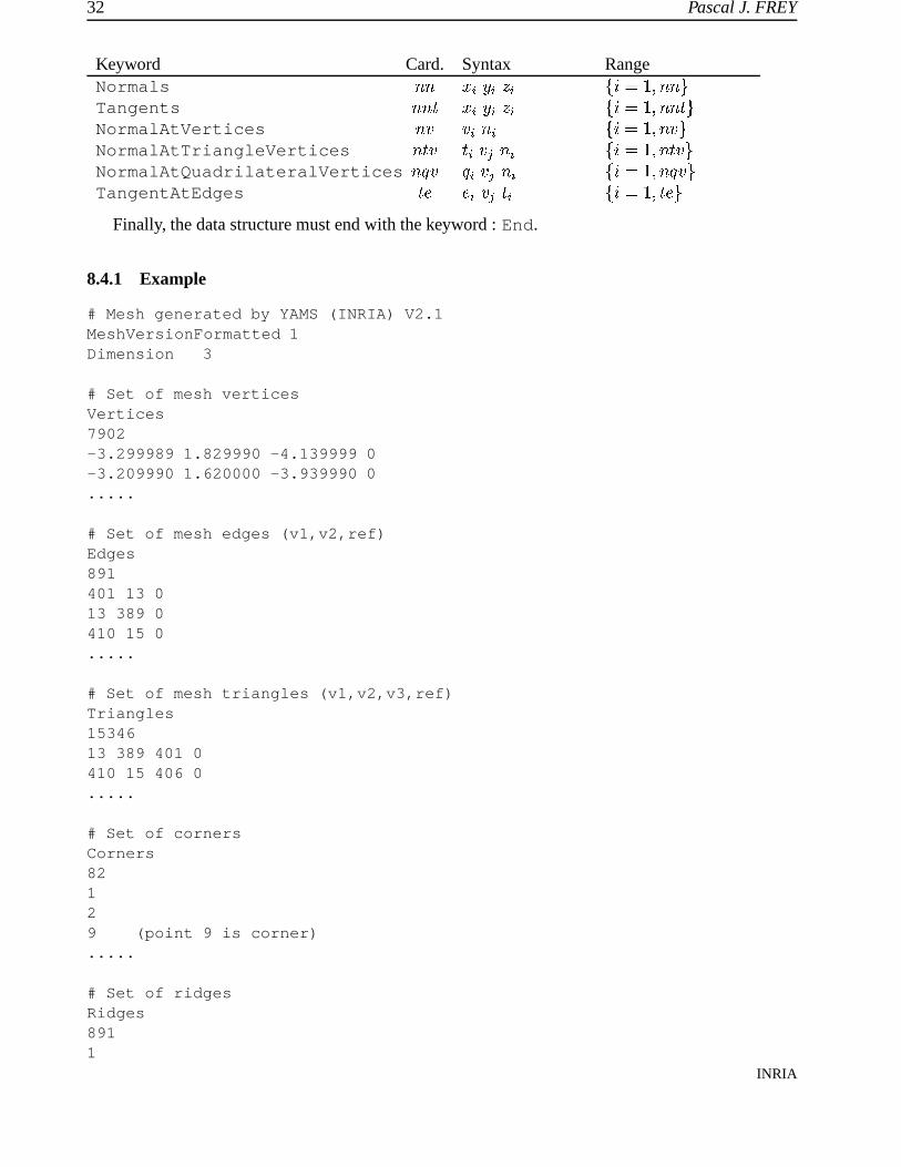
32 Pascal J. FREY
Keyword Card. Syntax RangeNormals � � � � � � � � � � �Tangents � �
� � � � � � � � � � �NormalAtVertices � � � �� � � � � � � �NormalAtTriangleVertices �
� � � � � � � � � � � � � �
NormalAtQuadrilateralVertices ��� � � � � �� � � � � ��� � �TangentAtEdges
� � � � �� � � � � � � �
Finally, the data structure must end with the keyword : End.
8.4.1 Example
# Mesh generated by YAMS (INRIA) V2.1MeshVersionFormatted 1Dimension 3
# Set of mesh verticesVertices7902-3.299989 1.829990 -4.139999 0-3.209990 1.620000 -3.939990 0.....
# Set of mesh edges (v1,v2,ref)Edges891401 13 013 389 0410 15 0.....
# Set of mesh triangles (v1,v2,v3,ref)Triangles1534613 389 401 0410 15 406 0.....
# Set of cornersCorners82129 (point 9 is corner).....
# Set of ridgesRidges8911
INRIA

YAMS : a fully automatic surface remeshing tool 33
23.....
# List of normal vectorsNormals82990.244684 0.031587 -0.9690880.254205 0.033309 -0.966576.....
# Normals at verticesNormalAtVertices7006406 1391412 6 (normal vector 6 associated with vertex 412).....
End
8.5 The msh2 format
This file format is a very crude data format provided for bacward compatibility purposes. It is com-posed of two ASCII files, xxx.points and xxx.faces. The file .points has the followingstructure :� �� � � �� � � representing the vertex coordinates in single precision and the vertex reference. The file .facesrepresents the mesh topology and contains the following records :� �� � � � � �
� � � � � � � � � � � � � �
where � is either 3 (triangles) or 4 (quad), � represents a vertex number, � � � is the reference of thesub-domain containing the face and � � � � are the edge references.
8.6 the bb format
This ASCII file contains scalar values associated with a mesh file. It is used to specify the sizesassociated with mesh vertices. This file has the following structure :� � � �
� , ��� � � � ���The values � represent the local sizes associated with mesh vertices. Notice that the values
� and�on the first record must be specified as it (other codes use different values).
RT n˚0252

34 Pascal J. FREY
8.7 List of FAQ’s
The aim of this section is to provide a set of questions/answers that can help the user to obtain acorrect and accurate surface mesh from a given surface triangulation. In some cases, the answers arevery short, while for others, the answer is more elaborate. In any case, the authors encourage the userto play with the various options and parameters to get a better understanding of YAMS behavior.
Q1. How to get a high-quality mesh suitable for FE computations ?Option -O 1will do the job. Also use option -O 0 on a given mesh to improve the mesh quality.Notice also that the mesh quality is related to the Gradation parameter value (a value of 1.3should give good results).
Q2. How to get an optimal mesh ?
Usually, the resulting mesh is a good compromise between the quality of the geometric ap-proximation, the element shape quality and the number of elements. In this sense, the mesh is’optimal’.Notice that this mesh is not Delaunay ! (as the Delaunay property needs to be defined onsurfaces...).
Q3. How to control the number of nodes/elements ?
It is not possible to control precisely the number of vertices in a mesh. However, running YAMStwo or three times and adjusting slightly the Tolerance or GeomApp parameters, you shouldbe able to get a mesh having roughly the desired number of vertices.
Q4. How to prevent the vertex positions to be modified ?
Use yams -ns to prevent the mesh vertices to be changed.
Q5. How to preserve specific mesh entities ?
In a mesh file Use the fields Requiredxx to constrain mesh entities in a mesh file.
Q6. How to deal with scanned data ?
After Marching Cubes reconstruction algorithms, first use option -O 9 to remove staircaseseffects. Then, on a second run, use options -O 1 or -O 2 to create a high-quality mesh or ageometric mesh.
Q7. How to remove small features ?
Set the parameter MinSize in the .yams file to a suitable value. Notice that this value isused to truncate the intrinsic metric. Hence, if the value is too high, the geometry of the surfacecan be affected. Another option is to increase the Tolerance value and use option -O 2 toremesh the surface within this tolerance (the tolerance value has to be larger than the size of thesmall feature to be removed).
Q8. How to control size variations ?
The mesh gradation is controlled by the Gradation parameter.
Q9. How to avoid local over-refinement ?
Usually, if the mesh density is locally to large, this is mainly due to small feature (or highly-curved regions) that may be artifacts. To prevent the creation of too small elements, set theparameter MinSize in the .yams file to a suitable value.
INRIA
YAMS : a fully automatic surface remeshing tool 35
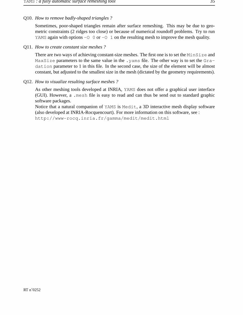
Q10. How to remove badly-shaped triangles ?
Sometimes, poor-shaped triangles remain after surface remeshing. This may be due to geo-metric constraints (2 ridges too close) or because of numerical roundoff problems. Try to runYAMS again with options -O 0 or -O 1 on the resulting mesh to improve the mesh quality.
Q11. How to create constant size meshes ?
There are two ways of achieving constant-size meshes. The first one is to set the MinSize andMaxSize parameters to the same value in the .yams file. The other way is to set the Gra-dation parameter to 1 in this file. In the second case, the size of the element will be almostconstant, but adjusted to the smallest size in the mesh (dictated by the geometry requirements).
Q12. How to visualize resulting surface meshes ?
As other meshing tools developed at INRIA, YAMS does not offer a graphical user interface(GUI). However, a .mesh file is easy to read and can thus be send out to standard graphicsoftware packages.Notice that a natural companion of YAMS is Medit, a 3D interactive mesh display software(also developed at INRIA-Rocquencourt). For more information on this software, see :http://www-rocq.inria.fr/gamma/medit/medit.html
RT n˚0252
36 Pascal J. FREY
References
[1] F. ALAUZET et al. (2001), Transient fixed point based unstructured mesh adaptation, ECCOMAS Com-putational Fluid Dynamic Conf., Swansea, UK.
[2] H. BOROUCHAKI, F. HECHT AND P.J. FREY (1998), Mesh gradation control, Int. J. Numer. MethodsEng., 43(6), 1143-1157.
[3] P.G. CIARLET (1991), Basic Error Estimates for Elliptic Problems, in Handbook of Numerical Analysis,vol II, Finite Element methods (Part 1), P.G. Ciarlet and J.L. Lions Eds, North Holland, 17-352.
[4] P.J. FREY AND P.L. GEORGE (2000), Mesh generation. application to finite elements, Hermès SciencePubl., Paris, Oxford, 814 pages.
[5] P.J. FREY AND H. BOROUCHAKI (1998), Geometric evaluation of finite element surface meshes, FiniteElements in Analysis and Design, 31, 33-53.
[6] P.J. FREY AND H. BOROUCHAKI (1998), Geometric Surface Mesh Optimization, Computing and Visua-lization in Science, 1, 113-121.
[7] P.J. FREY (2000), About surface remeshing, In Proc.of 9th Int. Meshing Roundtable, New Orleans, LO,USA, oct.
INRIA

Unite de recherche INRIA Lorraine, Technopole de Nancy-Brabois, Campus scientifique,615 rue du Jardin Botanique, BP 101, 54600 VILLERS LES NANCY
Unite de recherche INRIA Rennes, Irisa, Campus universitaire de Beaulieu, 35042 RENNES CedexUnite de recherche INRIA Rhone-Alpes, 655, avenue de l’Europe, 38330 MONTBONNOT ST MARTIN
Unite de recherche INRIA Rocquencourt, Domaine de Voluceau, Rocquencourt, BP 105, 78153 LE CHESNAY CedexUnite de recherche INRIA Sophia-Antipolis, 2004 route des Lucioles, BP 93, 06902 SOPHIA-ANTIPOLIS Cedex
EditeurINRIA, Domaine de Voluceau, Rocquencourt, BP 105, 78153 LE CHESNAY Cedex (France)
http://www.inria.frISSN 0249-6399