XX Technical Manual - Avid (7.24 MB) · PDF fileTechnical Manual GEN.0000000002866. 2 ... See...
113
MY10 XX™ Technical Manual GEN.0000000002866
Transcript of XX Technical Manual - Avid (7.24 MB) · PDF fileTechnical Manual GEN.0000000002866. 2 ... See...

MY10 XX™ Technical Manual
GEN.0000000002866

2
© Copyright SRAM LLC 2009For exploded diagram and part number information, please refer to the Spare Parts Catalog available on our website at www.sram.com.For order information, please contact your local SRAM distributor or dealer.Information contained in this publication is subject to change at any time without prior notice. For the latest technical information, please visit our website at www.sram.com.Your product‘s appearance may di!er from the pictures/diagrams contained in this catalog.Product names used in this document may be trademarks or registered trademarks of others.
SRAM LLC WarrantyEXTENT OF LIMITED WARRANTYSRAM warrants its products to be free from defects in materials or workmanship for a period of two years after original purchase. This warranty only applies to the original owner and is not transferable. Claims under this warranty must be made through the retailer where the bicycle or the SRAM compo-nent was purchased. Original proof of purchase is required. LOCAL LAWThis warranty statement gives the customer specific legal rights. The customer may also have other rights which vary from state to state (USA), from province to province (Canada), and from country to country elsewhere in the world.To the extent that this warranty statement is inconsistent with the local law, this warranty shall be deemed modified to be consistent with such law, under such local law, certain disclaimers and limita-tions of this warranty statement may apply to the customer. For example, some states in the United States of America, as well as some governments outside of the United States (including provinces in Canada) may:
Preclude the disclaimers and limitations of this warranty statement from limiting the statutory a. rights of the consumer (e.g. United Kingdom).Otherwise restrict the ability of a manufacturer to enforce such disclaimers or limitations.b.
LIMITATIONS OF LIABILITYTo the extent allowed by local law, except for the obligations specifically set forth in this warranty statement, in no event shall SRAM or its third party supplies be liable for direct, indirect, special, inci-dental, or consequential damages. LIMITATIONS OF WARRANTYThis warranty does not apply to products that have been incorrectly installed and/or adjusted ac-cording to the respective SRAM technical installation manual. The SRAM installation manuals can be found online at www.sram.com, www.RockShox.com, or www.avidbike.com.This warranty does not apply to damage to the product caused by a crash, impact, abuse of the product, non-compliance with manufacturers specifications of usage or any other circumstances in which the product has been subjected to forces or loads beyond its design.This warranty does not apply when the product has been modified.This warranty does not apply when the serial number or production code has been deliberately alte-red, defaced or removed.This warranty does not apply to normal wear and tear. Wear and tear parts are subject to damage as a result of normal use, failure to service according to SRAM recommendations and/or riding or instal-lation in conditions or applications other than recommended.
Wear and tear parts are identified as:Dust sealsBushingsAir sealing o-ringsGlide ringsRubber moving partsFoam ringsRear shock mounting hard-ware and main sealsUpper tubes (stanchions)Stripped threads/bolts (aluminium, titanium, ma-gnesium or steel)
Brake sleevesBrake padsChainsSprocketsCassettesShifter and brake cables (inner and outer)Handlebar gripsShifter gripsJockey wheelsDisc brake rotorsWheel braking surfaces
Bottomout padsBearingsBearing racesPawlsTransmission gearsTools
This warranty shall not cover damages caused by the use of parts of di!erent manufacturers.This warranty shall not cover damages caused by the use of parts that are not compatible, suitable and/or authorised by SRAM for use with SRAM components.This warranty shall not cover damages resulting from commercial (rental) use.

3 TABLE OF CONTENTS
TABLE OF CONTENTSMATCHMAKER X .........................................................................................................................................................................6
TECHNICAL DATA ....................................................................................................................................................................................................................... 6
TRIGGER SHIFTERS....................................................................................................................................................................6TECHNICAL DATA ....................................................................................................................................................................................................................... 6INSTALLATION ............................................................................................................................................................................................................................. 6DERAILLEUR CABLE INSTALLATION .............................................................................................................................................................................. 10SHIFTER CABLE CHANGE ......................................................................................................................................................................................................12MAINTENANCE ............................................................................................................................................................................................................................13
FRONT DERAILLEURS ............................................................................................................................................................. 14TECHNICAL DATA ......................................................................................................................................................................................................................14INSTALLATION ............................................................................................................................................................................................................................14
BAND CLAMP STYLE FRONT DERAILLEURS (HIGH MOUNT) ...................................................................................................................... 14HINGE CLAMP STYLE FRONT DERAILLEURS (LOW MOUNT) ..................................................................................................................... 15DIRECT MOUNT STYLE FRONT DERAILLEURS ................................................................................................................................................. 16
ADJUSTMENT AND CABLE INSTALLATION ..................................................................................................................................................................16TROUBLESHOOTING ................................................................................................................................................................................................................ 17
REAR DERAILLEUR ...................................................................................................................................................................18TECHNICAL DATA ......................................................................................................................................................................................................................18INSTALLATION ............................................................................................................................................................................................................................18LIMIT SCREW ADJUSTMENTS ..............................................................................................................................................................................................19REAR DERAILLEUR CABLE AND HOUSING ................................................................................................................................................................ 20INDEX SHIFTING ADJUSTMENT ..........................................................................................................................................................................................21CHAIN GAP ADJUSTMENT .....................................................................................................................................................................................................21MAINTENANCE ............................................................................................................................................................................................................................21TROUBLESHOOTING ................................................................................................................................................................................................................21
CRANKSETS ...............................................................................................................................................................................22TECHNICAL DATA .....................................................................................................................................................................................................................22
GXP CRANKSETS ....................................................................................................................................................................................................... 22PARTS PREPARATION .............................................................................................................................................................................................................22INSTALLATION ...........................................................................................................................................................................................................................24PEDAL INSTALLATION ............................................................................................................................................................................................................25MAINTENANCE ...........................................................................................................................................................................................................................25
BB30 CRANKSETS .................................................................................................................................................................................................... 26PARTS PREPARATION .............................................................................................................................................................................................................26INSTALLATION ...........................................................................................................................................................................................................................27PEDAL INSTALLATION ........................................................................................................................................................................................................... 30MAINTENANCE .......................................................................................................................................................................................................................... 30REMOVAL .......................................................................................................................................................................................................................................31
PRESSFIT GXP CRANKSETS ................................................................................................................................................................................... 32COMPATIBILITY ..........................................................................................................................................................................................................................32PARTS PREPARATION .............................................................................................................................................................................................................32INSTALLATION ...........................................................................................................................................................................................................................34PEDAL INSTALLATION ............................................................................................................................................................................................................35MAINTENANCE ...........................................................................................................................................................................................................................36REMOVAL ......................................................................................................................................................................................................................................36
PRESSFIT30 CRANKSETS ........................................................................................................................................................................................37PARTS PREPARATION .............................................................................................................................................................................................................37INSTALLATION ...........................................................................................................................................................................................................................38PEDAL INSTALLATION ........................................................................................................................................................................................................... 40MAINTENANCE .......................................................................................................................................................................................................................... 40REMOVAL ..................................................................................................................................................................................................................................... 40

4 TABLE OF CONTENTS
BRAKE LEVER ........................................................................................................................................................................... 41TECHNICAL DATA ......................................................................................................................................................................................................................41
BRAKE CALIPERS & ROTORS ................................................................................................................................................. 41TECHNICAL DATA ......................................................................................................................................................................................................................41
XX BRAKE CALIPER & ROTOR INSTALLATION ................................................................................................................................................ 42XX BRAKE LEVER OVERHAUL .............................................................................................................................................................................. 43
PARTS AND TOOLS NEEDED FOR SERVICE: ...............................................................................................................................................................43XX BRAKE CALIPER OVERHAUL PROCEDURE ................................................................................................................................................ 50
PARTS AND TOOLS NEEDED FOR SERVICE: .............................................................................................................................................................. 50XX BRAKE HOSE LENGTH ADJUSTMENT ...........................................................................................................................................................57
PARTS AND TOOLS NEEDED FOR SERVICE: ...............................................................................................................................................................57XX BRAKE BLEED PROCEDURE ...........................................................................................................................................................................60
PARTS AND TOOLS NEEDED FOR SERVICE: .............................................................................................................................................................. 60DISC BRAKE PAD REPLACEMENT PROCEDURE ............................................................................................................................................. 67DISC BRAKE PAD AND ROTOR BED-IN PROCEDURE ................................................................................................................................... 69
CASSETTE ..................................................................................................................................................................................70TECHNICAL DATA .....................................................................................................................................................................................................................70
XX CASSETTE INSTALLATION .............................................................................................................................................................................. 70PARTS PREPARATION .............................................................................................................................................................................................................70REMOVAL .......................................................................................................................................................................................................................................71MAINTENANCE ............................................................................................................................................................................................................................71
XLOC ...........................................................................................................................................................................................72TECHNICAL DATA .....................................................................................................................................................................................................................72
XLOC HOSE LENGTH ADJUSTMENT ....................................................................................................................................................................72PARTS PREPARATION .............................................................................................................................................................................................................72
XLOC BLEED PROCEDURE ......................................................................................................................................................................................74PARTS PREPARATION .............................................................................................................................................................................................................74FRONT SUSPENSION TOOLS NEEDED FOR SERVICE .......................................................................................................................................... 80FRONT SUSPENSION TECHNOLOGY AND OIL VOLUMES .....................................................................................................................................81TORQUE SPECIFICATIONS ....................................................................................................................................................................................................81
BUSHING INSPECTION, LOWER LEG REMOVAL, AND SEAL SERVICE .................................................................................................... 82LOWER LEG REMOVAL ............................................................................................................................................................................................ 83LOWER LEG DUST SEAL SERVICE ....................................................................................................................................................................... 85XX MOTION CONTROL DAMPER SERVICE ........................................................................................................................................................ 87DUAL AIR SPRING SERVICE .................................................................................................................................................................................... 91
OPTIONAL - ALL TRAVEL CONFIGURATIONS ............................................................................................................................................................95AIR U-TURN SPRING SERVICE - REVELATION XX .......................................................................................................................................... 96LOWER LEG INSTALLATION .................................................................................................................................................................................102
FRAME FIT SPECIFICATIONS ...............................................................................................................................................104XX™ FRONT DERAILLEUR - LOW & HIGH CLAMP ......................................................................................................................................... 105XX™ FRONT DERAILLEUR - DIRECT MOUNT ...................................................................................................................................................107XX™ CRANKSETS ...................................................................................................................................................................................................... 110
AVID HYDRAULIC BRAKE SETUP GUIDE .............................................................................................................................111

SAFETY FIRST!At SRAM, we care about YOU. Please, always wear your safety
glasses and protective gloves when servicing your XX componentry.
Protect yourself! Wear your safety gear!
Important: Your XX parts may look different from those illustrated.

6 MATCHMAKER X
MATCHMAKER XTECHNICAL DATA
Material AL-6061-T6
Hardware Titanium T-25 TORX® Bolts
Options Shifter + Brake / Shifter + Brake + XLoc
Adjustability Medial/Lateral and Rotational Around the Handlebar
Mounting Ambidextrous
TRIGGER SHIFTERSTECHNICAL DATA
Version Front Rear
Compatibility SRAM XX 2x10 Only
Speeds 2 10
Technology Exact Actuation Ratio for 10 Speed
Mechanism Exact Actuation Ratio
Max. Shifts 1 3 up shifts / 1 down shift
Matchmaker Matchmaker and Matchmaker X Compatible
Shifter Cable Stainless Steel with PTFE Coating
Hardware Al-7075-T6 and Stainless steel, T-25 TORX® Bolts
Barrel Adjuster Composite
Clamp AL-6061-T6
Pull Lever Adjustable
Pull Lever Material Carbon Fiber
Release Lever Composite
Top Cover Carbon Fiber
Lower Cover Composite
Weight 183 g / pair (without shifter cable)
I N S T A L L A T I O NParts and tools needed for service:
Safety glasses
Gloves
T25 TORX™ wrench
Adjustable torque wrench up to 25 N·m (217 in-lb)
Friction paste
T I P S & T R I C K SCustomization The XX Shifters have two mounting positions to meet your ergonomic demands. To switch between the two positions, simply use a T25 TORX wrench to remove the shifter from it‘s handlebar clamp (no need to remove the clamp from the bar), and then use a 2.5 mm hex wrench to remove the dummy screw from the mounting base. Install the dummy screw in the alternate hole, and hand tighten. Re-install the shifter bolt and Use a T25 TORX wrench to torque to 2.8-3.4 N·m (25-30 in-lb).
T25 2.8 – 3.4 N·m (22 – 35 in-lb)

7 DISCREET CLAMP INSTALLATION
The lower shift lever is infinitely adjustable. Use a T25 TORX wrench to loosen the adjustment bolt. Position the shift lever to suit your ergonomic needs. Hand tighten the adjustment bolt.
WA R N I N G :We highly recommend the use of friction paste on the clamp contact surfaces of all XX components that are mounted to carbon fiber handlebars.
D I S C R E E T C L A M P I N S T A L L A T I O N
1 Either the XX Brake or XX Shifter can be mounted onto the handlebar first, depending on personal preference. To install the brake, slide the discreet clamp onto the handlebar, and then insert the brake lever into the clamp. Insert the brake clamp bolt and loosely tighten to hold the assembly together.
2 To install the shifter, slide the discreet clamp onto the handlebar, and then install the shifter onto the clamp.
T25 2.8 – 3.4 N·m (22 – 35 in-lb)

8 MATCHMAKER X INSTALLATION
3 Choose the position of the shifter and brake that best meets your ergonomic needs. Use a T25 TORX™ wrench to torque both the shifter clamp bolt and the brake clamp bolt to 5 – 6 N·m (44 – 53 in-lb).
T I P S & T R I C K SSee the Avid Hydraulic Brake Setup Guide for tips on proper brake setup.
M A T C H M A K E R X I N S T A L L A T I O N
1 Attach the XX shifter to the MatchMaker X (MMX) bracket with the shifter mounting bolt. Use a T25 TORX wrench to torque the shifter mounting bolt to 2.8 - 3.4 N·m (25-30 in-lb).
2 Install the MMX bracket nut on the inside surface of the MMX clamp. Position the MMX bracket assembly on the outside of the MMX clamp and loosely install the MMX bracket bolt to hold the assembly in place. Use a T25 TORX wrench to torque the bracket bolt to 4 - 5 N·m (25-30 in-lb).
3 Position the brake lever against the handlebar. Close the MMX clamp around the handlebar and brake lever. Insert the MMX clamp bolt and loosely tighten to hold the assembly together.
WA R N I N G :Never tighten the MMX clamp or XLoc clamp onto the handlebar without the brake lever in place. Clamping the MMX clamp or XLoc to the handlebar without the XX brake lever can apply very high stress to the handlebar leading to handlebar failure.
T25 5 – 6 N·m (44 – 53 in-lb)
T25 5 – 6 N·m (44 – 53 in-lb)
T25 5 – 6 N·m (44 – 53 in-lb)

9 XLOC INSTALLATION
4 Choose the position of the shifter and brake that best meets your ergonomic needs. Use a T25 TORX™ wrench to torque the MMX clamp bolt to 5 – 6 N·m (44 – 53 in-lb).
T I P S & T R I C K SSee the Avid Hydraulic Brake Setup Guide for tips on proper brake setup. The shifter angle can be changed by loosening the MMX bracket bolt, and repositioning the shifter. Use a T25 TORX™ wrench to torque the bracket bolt to 4 – 5 N·m (35 – 44 in-lb) once it is in position.
X L O C I N S T A L L A T I O N
1 Install the XLoc bracket nut in the channel on the inside surface of the XLoc clamp. Position the XLoc bracket on the outside of the MMX clamp and loosely install the MMX bracket bolt to hold the assembly in place.
2 Position the brake lever against the handlebar. Close the XLoc clamp around the handlebar and brake lever. Insert the XLoc clamp bolt and loosely tighten the bolt to hold the assembly together.
T25 5 – 6 N·m (44 – 53 in-lb)
T25 4 – 5 N·m (25 – 30 in-lb)

10 DERAILLEUR CABLE INSTALLATION
3 Choose the position of the brake lever that best meets your ergonomic needs. Use a T25 TORX™ wrench to torque the XLoc clamp bolt to 5 – 6 N·m (44 – 53 in-lb).
T I P S & T R I C K SSee the Avid Hydraulic Brake Setup Guide for tips on proper brake setup.
4 Attach the XLoc shifter to the XLoc bracket with the shifter mounting bolt. Use a T25 TORX wrench to torque the shifter mounting bolt to 2.8 - 3.4 N·m (25-30 in-lb).
T I P S & T R I C K SThe shifter angle can be changed by loosening the XLoc bracket bolt, and repositioning the shifter. Use a T25 TORX™ wrench to torque the bracket bolt to 4 – 5 N·m (35 – 44 in-lb) once it is in position.
Additional component installation procedures:
Brake Calipers Front Derailleur Rear Derailleur Cranksets
D E R A I L L E U R C A B L E I N S T A L L A T I O N
1 Measure, cut, and install shifter housing and ferrules. Check for binding by turning handlebars side-to-side.
Measure and cut the rear derailleur housing. Make sure it is neither too long or too short. Install housing ferrules, and install the housing on the bike.
T25 5 – 6 N·m (44 – 53 in-lb)
T25 2.8 – 3.4 N·m (25 – 30 in-lb)
T25 4 – 5 N·m (25 – 30 in-lb)
11 DERAILLEUR CABLE INSTALLATION
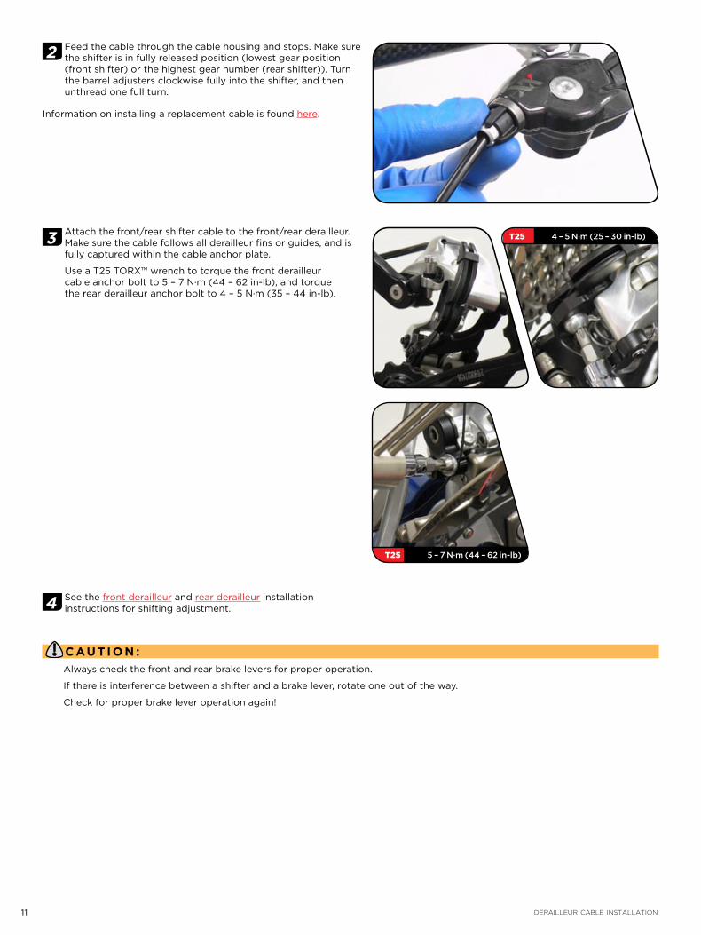
2 Feed the cable through the cable housing and stops. Make sure the shifter is in fully released position (lowest gear position (front shifter) or the highest gear number (rear shifter)). Turn the barrel adjusters clockwise fully into the shifter, and then unthread one full turn.
Information on installing a replacement cable is found here.
3 Attach the front/rear shifter cable to the front/rear derailleur. Make sure the cable follows all derailleur fins or guides, and is fully captured within the cable anchor plate.
Use a T25 TORX™ wrench to torque the front derailleur cable anchor bolt to 5 – 7 N·m (44 – 62 in-lb), and torque the rear derailleur anchor bolt to 4 – 5 N·m (35 – 44 in-lb).
4 See the front derailleur and rear derailleur installation instructions for shifting adjustment.
C AU TI O N :Always check the front and rear brake levers for proper operation.
If there is interference between a shifter and a brake lever, rotate one out of the way.
Check for proper brake lever operation again!
T25 4 – 5 N·m (25 – 30 in-lb)
T25 5 – 7 N·m (44 – 62 in-lb)

12 SHIFTER CABLE CHANGE
S H I F T E R C A B L E C H A N G E
I M P O R TA N T:Use only new high quality cable and compressionless cable housing with endcaps.
1 Make sure the shifter is in fully released position (lowest gear position (front shifter) or the highest gear number (rear shifter)).
2 Detach the cable from the derailleur.
3 Cut the cable off 6“ (15 cm) from the shifter barrel adjuster. Discard the old cable and cable housing.
4 Use a T10 TORX wrench to unscrew the shifter cover bolt. Remove the shifter cover by hand.
5 Use a pick to carefully guide the cable end out of the cable retainer slot. Discard the old cable and housing. Measure, cut, and install new derailleur housing.

13 SHIFTER CABLE CHANGE
6 Feed the new cable through the cable entry and out of the barrel adjuster. Make sure the cable end is fully seated in the cable retainer slot.
7 Replace the shifter cover. Use a T10 TORX wrench to hand tighten the shifter cover bolt.
I M P O R TA N T:Only hand tighten the shifter cover bolt. Do not over-tighten.
M A I N T E N A N C EClean the shifter using only water and mild soap.

14 FRONT DERAILLEURS
FRONT DERAILLEURSTECHNICAL DATA
Version High Mount Low Mount Direct Mount
Compatibility SRAM XX 2x10 Only
Speeds 2
Crankset Compatibility 26-39 / 28-42 / 30-45
Clamp Material Forged AL-6061-T6
Shifter Cable Stainless Steel with PTFE Coating
Hardware Al-7075-T6 and Stainless steel, T25 TORX® Bolts
Barrel Adjuster Composite with Soft Touch paint
Cable Routing Top or Bottom Pull
Chainstay Angle 66-69 degrees
Clamp Diameters 31.8 mm / 34.9 mm / 38.1 mm
Weight 120 g 118 g 116 g
I N S T A L L A T I O NParts and tools needed for service:
Safety glasses
T25 TORX™ wrench
Adjustable torque wrench up to 25 N·m (217 in-lb)
Cable cutter
WA R N I N G :Carbon frames can be damaged at higher torque values. Use extreme caution and use friction paste if available.
C AU TI O N :We highly recommend the use of friction paste on the clamp contact surfaces of all XX clamp style front derailleurs and shims when mounting to any frame material.
If friction paste is not available, torque clamp bolts to the torque value listed in brackets [ ].
B A N D C L A M P S T Y L E F R O N T D E R A I L L E U R S ( H I G H M O U N T )
1 Use a T25 TORX wrench to remove the clamp bolt from the derailleur and open the band clamp.
C AU TI O N :The band clamp can open quickly once the clamp bolt is removed. Please use caution when opening.
Only open the band clamp by removing the clamp bolt. The fixed clamp attachment bolt is not meant to be removed.
1 Lightly clamp the front derailleur to the seat tube so that there is 1-3 mm of clearance between the bottom of the derailleur cage outer plate and the tallest teeth of the large chainring.

15 HINGE CLAMP STYLE FRONT DERAILLEURS (LOW MOUNT)
2 Align the front derailleur cage outer plate to be parallel with the chainrings.
3 Use a T25 TORX™ wrench and torque the front derailleur clamp bolt to 3-4 N·m (27-35 in-lb) [5-7 N·m (44-62 in-lb)].
H I N G E C L A M P S T Y L E F R O N T D E R A I L L E U R S ( L O W M O U N T )
1 Lightly clamp the front derailleur to the seat tube so that there is 1-3 mm of clearance between the bottom of the derailleur cage outer plate and the tallest teeth of the large chainring.
2 Align the front derailleur cage outer plate to be parallel with the chainrings.
T25 3 – 4 N·m (27 – 35 in-lb) [5-7 N·m (44-62 in-lb)]
16 DIRECT MOUNT STYLE FRONT DERAILLEURS
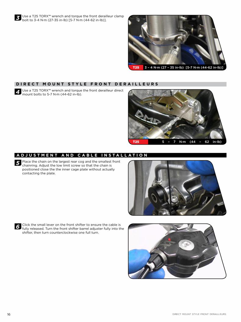
3 Use a T25 TORX™ wrench and torque the front derailleur clamp bolt to 3-4 N·m (27-35 in-lb) [5-7 N·m (44-62 in-lb)].
D I R E C T M O U N T S T Y L E F R O N T D E R A I L L E U R S
4 Use a T25 TORX™ wrench and torque the front derailleur direct mount bolts to 5-7 N·m (44-62 in-lb).
A D J U S T M E N T A N D C A B L E I N S T A L L A T I O N
5 Place the chain on the largest rear cog and the smallest front chainring. Adjust the low limit screw so that the chain is positioned close the the inner cage plate without actually contacting the plate.
6 Click the small lever on the front shifter to ensure the cable is fully released. Turn the front shifter barrel adjuster fully into the shifter, then turn counterclockwise one full turn.
T25 3 – 4 N·m (27 – 35 in-lb) [5-7 N·m (44-62 in-lb)]
T25 5 – 7 N·m (44 – 62 in-lb)

17 REAR DERAILLEUR
7 Feed the front shifter cable through the cable housing and cable stops. Run the cable under the cable anchor washer and pull taut.
8 Use a T25 TORX™ wrench to torque the cable anchor bolt to 5 N·m (44 in-lb). Shift the chain up and down several times to remove any initial slack from the cable.
9 Shift the chain to the smallest rear cog and largest front chainring. Use a T25 TORX to adjust the high limit screw so that the chain is positioned close the the outer cage plate without actually contacting the plate, and the chain does not come off the large chainring.
TROUBLESHOOTINGProblem Cause Remedy
Chain fails to change chainring Shift cable incorrectly clamped Check shift cable and correct as necessary: Cable clamp; cable housing stops; cable recess in shifter; cable tension
High / low limit screw poorly adjusted Correct limit screws
Clearance between cage and large chainring is too great/small
Correct gap between chainring and derailleur (1-3 mm between derailleur cage outer plate and top of tallest large chainring tooth
Chain falls over large / small chainring High / low limit screw poorly adjusted Correct limit screws
Force required to change gears is too high Excessive cable friction; pinched or poorly routed cable
Lubricate or replace cable and housing. Check for excessive bending of cable housing
Crank collides with front derailleur High gear limit screw incorrectly adjusted Correct high limit screw
Cage not parallel with chainring Correct the front derailleur position
Top Pull
Bottom Pull
T25 5 – 7 N·m (44 – 62 in-lb)
T25 5 – 7 N·m (44 – 62 in-lb)
T25
18 REAR DERAILLEUR
REAR DERAILLEURTECHNICAL DATA
Version XX Rear Derailleur
Speeds 10 speed for 2x10 system
Technology Exact Actuation Ratio; DiRT™ Direct Route Technology
Inner Cage Carbon Fiber Composite
Outer Cage Carbon Fiber Composite
Inner Link Forged Magnesium
Outer Link Forged AL-6061-T6
B-Bolt Al-7075-T6
B-Knuckle Forged Al-7075-T6
P-Knuckle Grilon Composite
Bearing Pulleys Sealed Ceramic Bearing pulleys
Hardware Titanium and AL-7075-T6; T25 TORX® bolts
Cage Length 93 mm
Cassette Compatibility Maximum 36 T
Weight 181 g
I N S T A L L A T I O NParts and tools needed for service:
Safety glasses
T25 TORX™ wrench
Adjustable torque wrench up to 25 N·m (217 in-lb)
Cable cutter
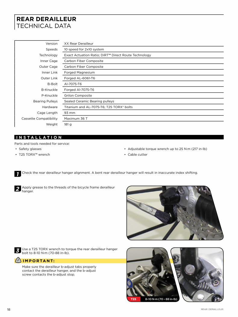
1 Check the rear derailleur hanger alignment. A bent rear derailleur hanger will result in inaccurate index shifting.
2 Apply grease to the threads of the bicycle frame derailleur hanger.
3 Use a T25 TORX wrench to torque the rear derailleur hanger bolt to 8-10 N·m (70-88 in-lb).
I M P O R TA N T:Make sure the derailleur b-adjust tabs properly contact the derailleur hanger, and the b-adjust screw contacts the b-adjust stop.
T25 8–10 N·m (70 – 88 in-lb)

19 REAR DERAILLEUR
4 Wrap the chain around the largest front chainring and the largest rear cog so that the ends of the chain meet below the chainstay, bypassing both the front and rear derailleurs. Pull the chain tight and note which rivet the end of the chain is nearest. Add one inner link so that you have an inner link on both ends of the chain, and a SRAM PowerLock.
I M P O R TA N T:Rear suspension frames: The rear shock needs to be in the fully compressed position to accurately size the chain. Remove all air pressure or remove the coil spring from the shock, and size the chain as instructed. After the chain is sized, re-inflate or re-install the coil spring according to your manufacturer’s instructions.
5 Working from the front of the bike, guide the chain through the front derailleur and over the smallest rear cog. Direct the chain around the front of and under the guide pulley of the rear derailleur. Guide the chain around the rear of the jockey pulley. Connect the ends of the chain with a SRAM PowerLock.
I M P O R TA N T:Make sure the chain does not contact any part of the derailleur cage, and is only riding on the pulleys.
L I M I T S C R E W A D J U S T M E N T S
6 Use a T25 TORX wrench to turn the limit screw marked ‘H’ on the outer link of the derailleur to align the center of the upper guide pulley with the outboard edge of the smallest cog.
7 While turning the crank, push the rear derailleur towards the larger cogs by hand. When the chain is on the largest cog, stop turning the crank and hold the derailleur in place. Use a T25 TORX wrench to turn the limit screw marked ‘L’ on the outer link of the derailleur to align the center of the upper guide pulley with the center of the largest cog.
T25
T25

20 REAR DERAILLEUR
R E A R D E R A I L L E U R C A B L E A N D H O U S I N GAdditional component installation procedures:
Brake Calipers Front Derailleur Rear Derailleur Cranksets
8 Measure, cut, and install shifter housing and ferrules. Check for binding by turning handlebars side-to-side.
Measure and cut the rear derailleur housing. Make sure it is neither too long or too short. Install housing ferrules, and install the housing on the bike.
9 Feed the cable through the cable housing and stops. Make sure the rear shifter is in the fully released position (highest gear). Turn the barrel adjuster clockwise fully into the shifter, and then unthread one full turn.
10 Attach the rear shifter cable to the rear derailleur. Make sure the cable follows all derailleur fins or guides, and is fully captured within the cable anchor plate. Use a T25 TORX™ wrench to torque the rear derailleur anchor bolt to 4 – 5 N·m (35 – 44 in-lb).
11 Cut the cable 3 cm from where it exits the cable anchor plate to avoid interference with the upper guide pulley and chain. Crimp a cable end tip onto the cable.
T25 4 – 5 N·m (25 – 30 in-lb)
3 cm

21 CRANKSETS
I N D E X S H I F T I N G A D J U S T M E N T
12 While turning the crank, downshift the derailleur one cog (easier gear). If the chain hesitates or does not fully shift, increase the cable tension by turning the shifter barrel adjuster counter-clockwise. If the chain shifts more than one cog, decrease the cable tension by turning the shifter barrel adjuster clockwise. Upshift back to the smallest cog, and then downshift one cog (easier gear) again. Repeat adjusting the cable tension until the shifting is accurate. Shift the chain up and down the cassette several times to ensure that your derailleur is indexing properly.
C H A I N G A P A D J U S T M E N T
13 Shift the chain onto the small chainring. While turning the crank, shift the rear derailleur to the largest cog. Use a T25 TORX wrench to turn the b-adjust screw until the chain gap equals approximately 12 mm from the tip of the cog to the tip of the upper guide pulley. While turning the crank, shift the derailleur across the range of the cassette and re-check the chain gap. The chain gap should average 12 mm across the range.
M A I N T E N A N C EWipe debris from between the cage plates and parallelogram linkage. Clean the derailleur with clean or soapy water. Rinse the derailleur with clean water and let air dry. Do NOT use a pressure washer.
Ceramic bearings require regular maintenance. Re-grease bearings using SKF LGHP2 grease after 100 hours of use in dry conditions or immediately following any significant exposure to water (riding in heavy rain, water crossings).
Use a T25 TORX wrench to remove the derailleur pulley bolts.1.
Using a pick, carefully remove external seals from the pulleys, and rubber bearing seal from the face of the bearings.2.
Load SKF LGHP 2 grease into syringe. Apply grease, ensuring that bearings are completely covered, including between 3. bearings.
Press the rubber bearing seal back into place.4.
Apply light coating of grease to the inside surface of the external seal. Press external seals into place.5.
Wipe away any excess grease with a clean cloth.6.
Re-install the pulleys. The Lower pulley is directional; the words ‘Lower Pulley’ and a directional arrow are marked on the 7. outside face of the pulley to identify it from the non-directional upper pulley.
TROUBLESHOOTINGProblem Cause Remedy
Chain jumps from smallest cog to frame dropout High gear limit screw is not adjusted properly Turn in limit screw ‘H’ until the guide pulley is aligned with the outboard edge of the smallest cog
Difficult or impossible to shift chain onto smallest cog High gear limit screw is not adjusted properly Unscrew limit screw ‘H’ until the guide pulley is aligned with the outboard edge of the smallest cog
Chain jumps over largest cog and falls between the spokes and largest cog, or inner cage plate contacts spokes
Low gear limit screw is not adjusted properly Turn in limit screw ‘L’ until the center of the guide pulley is aligned with the center of the largest cog
Rear derailleur or derailleur hanger is bent Straighten or replace
Delayed Shifting Clearance between guide pulley / sprocket is too large
Adjust b-adjust screw by turning it counter-clockwise
Rough shifting behavior Clearance between guide pulley / sprocket is too small
Adjust b-adjust screw by turning it clockwise
Shifts more gears onto smaller sprockets than intended Shift cable insufficiently tensioned Turn barrel adjuster on the shifter counter-clockwise
Delayed shifting onto larger sprocket Shift cable insufficiently tensioned Turn barrel adjuster on the shifter counter-clockwise
Delayed shifting onto smaller sprocket Shift cable is too tight Turn barrel adjuster on the shifter clockwise
Excessive cable friction, pinched or poorly routed cable
Lubricate or replace cable and housing. Check for excessive bending of cable housing
Increase Tension
Decrease Tension
T25
12 mm
22 CRANKSETS
CRANKSETSTECHNICAL DATA
Version GXP PressFit GXP BB30 PressFit 30
Chainline 49.5 mm
Chainring Material AL-7075-T651
Chainring Color Tungsten Grey and Silver
Chainring Bolts AL-7075-T6 / Stainless Steel
Crankarm Materials Integrated Carbon Composite
Compatible Chain Type 10-speed SRAM Chains
Chainring Options 26-39 / 28-42
Bottom Bracket Bearings BlackBox® Ceramic Bearings
Chainring Bolt Circle Diameter 120/80
Crankarm Length Options 170 mm/175 mm
Weight 754 g 694 g
I M P O R TA N T:To ensure that your crankset and bottom bracket perform properly, we highly recommend that you have them installed by a qualified bicycle mechanic. We also urge you to follow our recommendations to help make your riding experience more enjoyable and trouble-free.
G X P C R A N K S E T S
P A R T S P R E P A R A T I O NParts and tools needed for service:
Safety glasses
8 mm hex wrench
Bottom bracket installation tool (Truvativ GXP / Park™ BBT9 or equivalent)
Torque wrench
Grease
1 Assure the frame’s bottom bracket shell threads are clean and undamaged; there should be no paint or dirt present. Have your bottom bracket shell chased and faced by a professional bicycle mechanic for best results. Make sure the threads of your GXP bottom bracket match the threads in the bottom bracket shell of your frame: IT for Italian threading (etched on the bottom bracket cup), or BSA for standard threading.

23 GXP CRANKSETS
2 Apply grease to the bottom bracket and frame surfaces as illustrated, including the inside face of the bearing seals. The seals should be pressed into the bottom bracket cups so that the outer lip seats firmly into the bottom bracket cup groove.
I M P O R TA N T:The drive side bearing seal has a larger inner diameter than the non-drive side seal.
3 Use calipers to measure your frame’s bottom bracket shell width. 68 mm bottom bracket shells require one 2.5 mm spacer on each side of the bottom bracket shell. 73 mm bottom bracket shells do not require spacers.

24 GXP CRANKSETS
I N S T A L L A T I O N
4 68 mm BB shell: install one 2.5 mm spacer on each bottom bracket cup.
68 and 73 mm BB shell: Thread the drive side bottom bracket cup counter-clockwise into the frame until the flange (or spacer) contacts the bottom bracket shell face. Torque to 34–41 N·m (301–363 in-lb).
Thread the non-drive side bottom bracket cup clockwise into the frame until the flange (or spacer) contacts the bottom bracket shell face. Torque to 34–41 N·m (301–363 in-lb).
5 Slide the drive side crank spindle through the drive side bottom bracket cup until the splines come through the non-drive side bottom bracket cup, and the spindle stops.
6 Install the non-drive side crankarm onto the crank spindle using an 8 mm hex and torque to 48–54 N·m (425–478 in-lb).
I M P O R TA N T:Check the assembly for play by rocking the crank arms back and forth away from frame. If the crank moves, tighten crank arm bolt until no play is detected. If maximum torque of 54 N·m (478 in-lb) has been achieved, remove the crank arm from the spindle, apply additional grease and repeat installation procedures until play is eliminated.
GXP 34 – 41 N·m (301 – 363 in-lb)
8 mm 48 – 54 N·m (425 – 478 in-lb)

25 GXP CRANKSETS
P E D A L I N S T A L L A T I O N
7 Grease the pedal threads and install pedals on the crankarms. Torque to 47-54 N·m (461-477 in-lb). Use pedal washers if the pedal contact surface is not flat and smooth.
I M P O R TA N T:The drive side pedal is right hand thread. The non-drive side pedal is left hand thread.
M A I N T E N A N C EUse only water and a mild soap to clean the crankset and bottom bracket. Do NOT use a pressure washer.
I M P O R TA N T:If creaking of the assembly occurs, check that all parts are torqued to specification, and grease is liberally applied on all surfaces noted. Verify that chainring bolts are torqued to 8–9 N·m (80–90 in-lb). If creaking continues, consult your local Truvativ dealer for assistance.
47 – 54 N·m (416 – 478 in-lb)

26 BB30 CRANKSETS
B B 3 0 C R A N K S E T S
P A R T S P R E P A R A T I O NParts and tools needed for service:
Safety glasses
30 mm bearing installation tool #00-6415-032-020
10 mm hex wrench
Headset press (Park Tool Co.© HHP-2 or equivalent)
Torque wrench
Grease
Rubber Mallet
1 Ensure the frame’s bottom bracket shell is clean and free of metal chips, excess paint, or dirt.
2 Carefully remove the bearing shields from the bottom bracket bearings. You may need to use a pick to free the shields from the bearings.
3 Apply grease to the inside surfaces of the bottom bracket shell, and the bottom bracket grooves. Apply light grease to the crank spindle splines and and spindle threads.
I M P O R TA N T:It is not necessary to face or machine the bottom bracket shell to use the BB30 system.

27 BB30 CRANKSETS
I N S T A L L A T I O N
WA R N I N G :Wear eye protection during the installation process. The BB30 retaining clips have sharp edges and can cause serious eye injury if they spring from bottom bracket during installation.
4 Using a small flat blade screwdriver, gently install the square end of the retaining clip into the bottom bracket groove, then work the retaining clip into the groove until it is fully seated in the groove. Ensure retaining clip is fully seated in groove. Repeat for the opposite side.
I M P O R TA N T:Bearing shields must be removed from the bottom bracket cups prior to installation.
5 Install the frame guide part of the SRAM BB30 Bearing Installation Toolkit onto a headset press with the stepped side facing away from the headset press handle. Insert the headset press into the bottom bracket shell.
6 Install a BB30 bearing onto the bearing installation part (with the blue seal facing the install part), and install the bearing installation part onto the headset press.
7 Press the bearing into bottom bracket shell until butted against the retaining clip. Repeat the process for the other bearing. Consult your headset press manufacturer’s instructions for proper use of the headset press.
C AU TI O N :Attempting to install both bearings simultaneously can damage the bearings and/or frame.
28 BB30 CRANKSETS
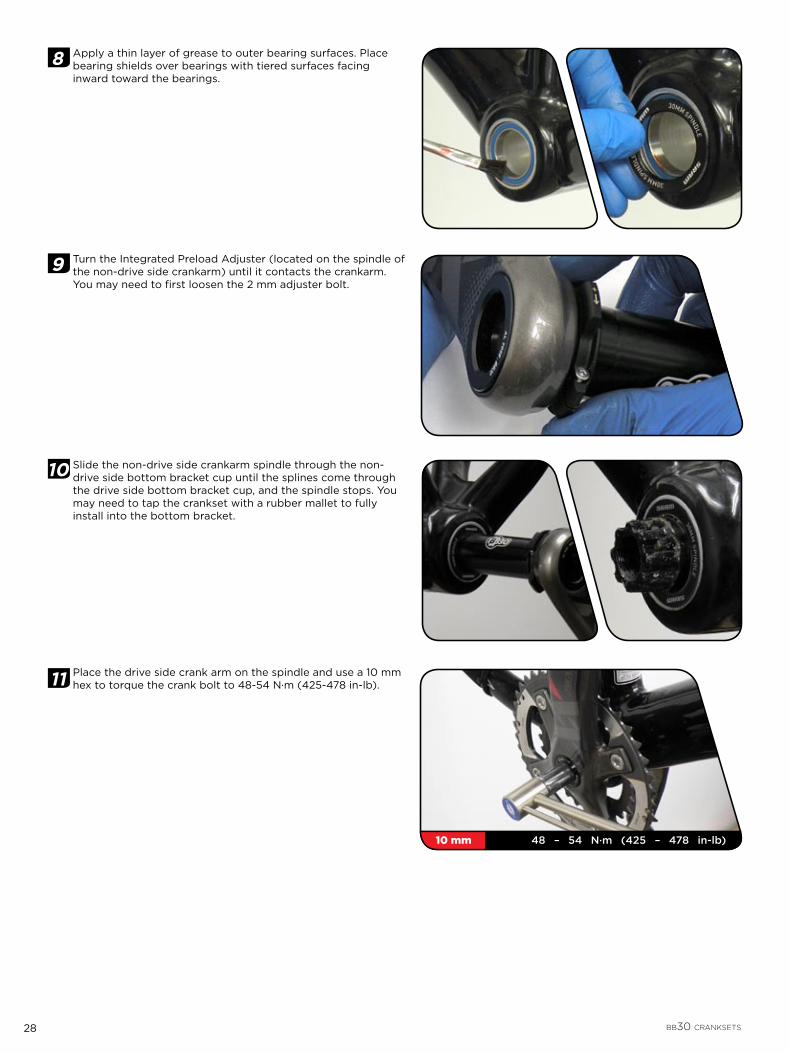
8 Apply a thin layer of grease to outer bearing surfaces. Place bearing shields over bearings with tiered surfaces facing inward toward the bearings.
9 Turn the Integrated Preload Adjuster (located on the spindle of the non-drive side crankarm) until it contacts the crankarm. You may need to first loosen the 2 mm adjuster bolt.
10 Slide the non-drive side crankarm spindle through the non-drive side bottom bracket cup until the splines come through the drive side bottom bracket cup, and the spindle stops. You may need to tap the crankset with a rubber mallet to fully install into the bottom bracket.
11 Place the drive side crank arm on the spindle and use a 10 mm hex to torque the crank bolt to 48-54 N·m (425-478 in-lb).
10 mm 48 – 54 N·m (425 – 478 in-lb)
29 BB30 CRANKSETS
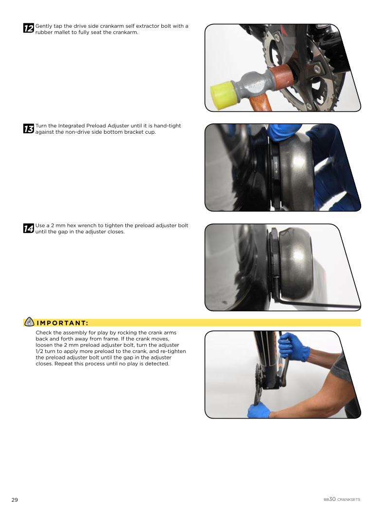
12 Gently tap the drive side crankarm self extractor bolt with a rubber mallet to fully seat the crankarm.
13 Turn the Integrated Preload Adjuster until it is hand-tight against the non-drive side bottom bracket cup.
14 Use a 2 mm hex wrench to tighten the preload adjuster bolt until the gap in the adjuster closes.
I M P O R TA N T:Check the assembly for play by rocking the crank arms back and forth away from frame. If the crank moves, loosen the 2 mm preload adjuster bolt, turn the adjuster 1/2 turn to apply more preload to the crank, and re-tighten the preload adjuster bolt until the gap in the adjuster closes. Repeat this process until no play is detected.

30 BB30 CRANKSETS
P E D A L I N S T A L L A T I O N
15 Grease the pedal threads and install pedals to the crankarms. Torque to 47-54 N·m (461-477 in-lb). Use pedal washers if the pedal contact surface is not flat and smooth.
I M P O R TA N T:The drive side pedal is right hand thread. The non-drive side pedal is left hand thread.
M A I N T E N A N C EUse only water and a mild soap to clean the crankset and bottom bracket. Do NOT use a pressure washer.
I M P O R TA N T:If creaking of the assembly occurs, check that all parts are torqued to specification, and grease is liberally applied on all surfaces noted. Verify that chainring bolts are torqued to 8–9 N·m (80–90 in-lb). If creaking continues, consult your local Truvativ dealer for assistance.
Bearings require regular maintenance. Re-grease bearings after 100 hours of use in dry conditions or immediately following any significant exposure to water; such as riding in heavy rain or through water crossings.
R E M O V A L
WA R N I N G :Wear eye protection during the installation process. The BB30 retaining clips have sharp edges and can cause serious eye injury if they spring from bottom bracket during installation
1 Using a 10 mm hex, remove the drive side crank arm from the spindle with the self extracting crank bolt (not pictured).
2 Remove the non- drive side crankarm and spindle from the bottom bracket. It may be necessary to use a rubber mallet to gently tap the spindle toward the frame to free it (not pictured).
3 Tilt BB30 removal tool inward and position so that it is seated on the inside face of the bearing.
47 – 54 N·m (416 – 478 in-lb)
31 BB30 CRANKSETS
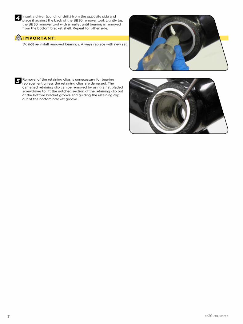
4 Insert a driver (punch or drift) from the opposite side and place it against the back of the BB30 removal tool. Lightly tap the BB30 removal tool with a mallet until bearing is removed from the bottom bracket shell. Repeat for other side.
I M P O R TA N T:Do not re-install removed bearings. Always replace with new set.
5 Removal of the retaining clips is unnecessary for bearing replacement unless the retaining clips are damaged. The damaged retaining clip can be removed by using a flat bladed screwdriver to lift the notched section of the retaining clip out of the bottom bracket groove and guiding the retaining clip out of the bottom bracket groove.

32 PRESSFIT GXP CRANKSETS
P R E S S F I T G X P C R A N K S E T S
I M P O R TA N T:To ensure that your PressFit GXP crankset performs properly and to help make your riding experience more enjoyable and trouble-free, we highly recommend that you have it installed by a qualified bicycle mechanic. Installation of the adapter does not have to be permanent. However, removal of the adapter can damage the cups and bearings. Do not re-use the adapter after removal from the frame shell. The adapter will only work in undamaged frames in good condition. The adapter must NOT be used as a way to repair frames with damaged press fit bottom bracket shells. Improper use, installation or removal of the adapter will void your warranty and can void the warranty for your frame.
C O M P A T I B I L I T YPressFit GXP MTB Bottom Bracket: enables the use of SRAM and Truvativ GXP MTB triple cranksets in frames designed with sleeveless (PressFit) bottom bracket shells of 89.5 mm or 92 mm width, and 41 mm diameter.
P A R T S P R E P A R A T I O NParts and tools needed for service:
Safety glasses
8 mm hex wrench
Headset press (Park Tool Co.© HHP-2 or equivalent)
Calipers
Torque wrench
Grease
Pick
1 Assure the frame’s bottom bracket shell is clean and free of metal chips, excess paint, or dirt.
2 Carefully remove the bearing shields from the bottom bracket cups. You may need to use a pick to free the shields from the bottom bracket cups.

33 PRESSFIT GXP CRANKSETS
3 Apply grease to the bottom bracket and frame surfaces as illustrated, including the inside face of the bearing seals, and the wave washer. The seals should be pressed into the bottom bracket cups so that the outer lip seats firmly into the bottom bracket cup groove.
I M P O R TA N T:It is not necessary to face or machine the bottom bracket shell to use the PressFit GXP system.
4 Use calipers to measure your frame’s bottom bracket shell width.
89.5 mm bottom bracket shells require one 2.5 mm spacer on the drive side bottom bracket cup, between the bb shell and the bb cup.
92 mm bottom bracket shells do not require any spacers.

34 PRESSFIT GXP CRANKSETS
I N S T A L L A T I O N
1 89.5 mm BB shell: install one 2.5 mm spacer on the drive side bottom bracket cup.
I M P O R TA N T:Bearing shields must be removed from the bottom bracket cups prior to installation (step 2).
2 Using a headset press, press the drive side bottom bracket cup into bottom bracket shell until the bottom bracket cup flange (or spacer) is fully seated against the bottom bracket shell. Repeat process for non-drive side bottom bracket cup. Consult your headset press manufacturer’s instructions for proper use of the headset press.
C AU TI O N :Attempting to install both bearings simultaneously can damage the bearings and/or frame.
3 Install the wave washer and then the drive side bearing shield onto the spindle, making sure the bearing shield is oriented correctly. The stepped lip on the bearing shield should face the bottom bracket shell.
I M P O R TA N T:The drive side bearing shield inner diameter has a circular design. The non-drive side bearing shield inner diameter has a “flower” like design.
4 Slide the drive side crankarm spindle through the drive side bottom bracket cup until the splines come through the non-drive side bottom bracket cup, and the spindle stops.

35 PRESSFIT GXP CRANKSETS
5 Install the non-drive side bearing shield onto the spindle, making sure the bearing shield is oriented correctly. The stepped lip on the bearing shield should face the bottom bracket shell (not pictured).
6 Apply grease to the threads of non-drive side crank bolt. Place the non-drive side crank arm on the spindle and use a 8 mm hex to torque the crank bolt to 48-54 N·m (425-478 in-lb).
I M P O R TA N T:Check the assembly for play by rocking the crank arms back and forth away from frame. If the crank moves, tighten crank arm bolt until no play is detected. If maximum torque of 54 N·m (478 in-lb) has been achieved, remove the crank arm from the spindle, apply additional grease and repeat installation procedures until play is eliminated.
P E D A L I N S T A L L A T I O N
1 Grease the pedal threads and install pedals to the crankarms. Torque to 47-54 N·m (461-477 in-lb). Use pedal washers if the pedal contact surface is not flat and smooth.
I M P O R TA N T:The drive side pedal is right hand thread. The non-drive side pedal is left hand thread.
8 mm 48 – 54 N·m (425 – 478 in-lb)
47 – 54 N·m (416 – 478 in-lb)

36 PRESSFIT GXP CRANKSETS
M A I N T E N A N C EUse only water and a mild soap to clean the crankset and bottom bracket. Do NOT use a pressure washer.
I M P O R TA N T:If creaking of the assembly occurs, check that all parts are torqued to specification, and grease is liberally applied on all surfaces noted. Verify that chainring bolts are torqued to 8–9 N·m (80–90 in-lb). If creaking continues, consult your local Truvativ dealer for assistance.
Bearings require regular maintenance. Re-grease bearings after 100 hours of use in dry conditions or immediately following any significant exposure to water; such as riding in heavy rain or through water crossings.
R E M O V A LUse the self-extracting crank bolt assembly or crank puller (if applicable) to remove the non-drive side crank arm. Use a rubber mallet to gently tap the end of the crank spindle towards the frame, and slide it out of the bottom bracket. Remove the bearing shields from the bottom bracket cups (not pictured).
The bottom bracket should be removed by applying force on the internal adapter cup wall, not the bearing (not pictured).

37 PRESSFIT30 CRANKSETS
P R E S S F I T 3 0 C R A N K S E T S
I M P O R TA N T:To ensure that your PressFit30 crankset performs properly and to help make your riding experience more enjoyable and trouble-free, we highly recommend that you have it installed by a qualified bicycle mechanic. Installation of the adapter does not have to be permanent. However, removal of the adapter can damage the cups and bearings. Do not re-use the adapter after removal from the frame shell. The adapter will only work in undamaged frames in good condition. The adapter must NOT be used as a way to repair frames with damaged press fit bottom bracket shells. Improper use, installation or removal of the adapter will void your warranty and can void the warranty for your frame.
P A R T S P R E P A R A T I O NParts and tools needed for service:
Safety glasses
2 mm, 10 mm hex wrenches
Headset press (Park Tool Co.© HHP-2 or equivalent)
Rubber Mallet
Torque wrench
Grease
Pick
1 Assure the frame’s bottom bracket shell is clean and free of metal chips, excess paint, or dirt.
I M P O R TA N T:It is not necessary to face or machine the bottom bracket shell to use the PressFit30 system.
2 Carefully remove the bearing shields from the bottom bracket cups. You may need to use a pick to free the shields from the bottom bracket cups.
3 Apply grease to the bottom bracket and frame surfaces as illustrated, including the outside face of the bearings, and the drive side bottom bracket cup o-ring. Apply grease to the spindle threads, splines, and races (the smooth part of the spindle near the integrated preload adjuster).
38 PRESSFIT30 CRANKSETS
I N S T A L L A T I O N
I M P O R TA N T:Bearing shields must be removed from the bottom bracket cups prior to installation (step 2).
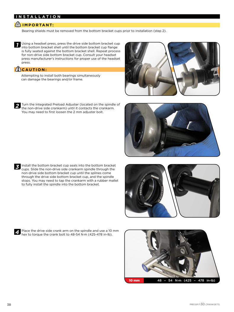
1 Using a headset press, press the drive side bottom bracket cup into bottom bracket shell until the bottom bracket cup flange is fully seated against the bottom bracket shell. Repeat process for non-drive side bottom bracket cup. Consult your headset press manufacturer’s instructions for proper use of the headset press.
C AU TI O N :Attempting to install both bearings simultaneously can damage the bearings and/or frame.
2 Turn the Integrated Preload Adjuster (located on the spindle of the non-drive side crankarm) until it contacts the crankarm. You may need to first loosen the 2 mm adjuster bolt.
3 Install the bottom bracket cup seals into the bottom bracket cups. Slide the non-drive side crankarm spindle through the non-drive side bottom bracket cup until the splines come through the drive side bottom bracket cup, and the spindle stops. You may need to tap the crankarm with a rubber mallet to fully install the spindle into the bottom bracket.
4 Place the drive side crank arm on the spindle and use a 10 mm hex to torque the crank bolt to 48-54 N·m (425-478 in-lb).
10 mm 48 – 54 N·m (425 – 478 in-lb)

39 PRESSFIT30 CRANKSETS
5 Gently tap the drive side crankarm self extractor bolt with a rubber mallet to fully seat the crankarm.
6 Turn the Integrated Preload Adjuster until it is hand-tight against the non-drive side bottom bracket cup.
7 Use a 2 mm hex wrench to tighten the preload adjuster bolt until the gap in the adjuster closes.
I M P O R TA N T:Check the assembly for play by rocking the crank arms back and forth away from frame. If the crank moves, loosen the 2 mm preload adjuster bolt, turn the adjuster 1/2 turn to apply more preload to the crank, and re-tighten the preload adjuster bolt until the gap in the adjuster closes. Repeat this process until no play is detected.

40 PRESSFIT30 CRANKSETS
P E D A L I N S T A L L A T I O N
1 Grease the pedal threads and install pedals to the crankarms. Torque to 47-54 N·m (461-477 in-lb). Use pedal washers if the pedal contact surface is not flat and smooth.
I M P O R TA N T:The drive side pedal is right hand thread. The non-drive side pedal is left hand thread.
M A I N T E N A N C EUse only water and a mild soap to clean the crankset and bottom bracket. Do NOT use a pressure washer.
I M P O R TA N T:If creaking of the assembly occurs, check that all parts are torqued to specification, and grease is liberally applied on all surfaces noted. Verify that chainring bolts are torqued to 8–9 N·m (80–90 in-lb). If creaking continues, consult your local Truvativ dealer for assistance.
Bearings require regular maintenance. Re-grease bearings after 100 hours of use in dry conditions or immediately following any significant exposure to water; such as riding in heavy rain or through water crossings.
R E M O V A LUse the self-extracting crank bolt assembly to remove the drive side crank arm. Use a rubber mallet to gently tap the end of the crank spindle towards the frame, and slide it out of the bottom bracket. Remove the bearing shields from the bottom bracket cups (not pictured).
The bottom bracket should be removed by applying force on the internal adapter cup wall, not the bearing (not pictured).
47 – 54 N·m (416 – 478 in-lb)

41 BRAKE LEVER
BRAKE LEVERTECHNICAL DATA
Version XX Brake Lever
Material Forged Magnesium Lever Body, Carbon Fiber Lever Blade
Hardware Titanium T25 TORX® Bolts
Adjustments Tool-Free Pad Contact-Point Adjustment; Tooled Reach Adjust
Technology TaperBore; Power Reserve Geometry; Ambidextrous
Compatiblility Matchmaker X Compatible
Brake Fluid DOT 5.1 Fluid
BRAKE CALIPERS & ROTORSTECHNICAL DATA
Version XX Brake Caliper
Material Forged Magnesium
Hardware Titanium T25 TORX® Bolts
Rotor Material Two-Piece Construction: AL-7075-T6 and Stainless Steel, Riveted
Pad Material Organic, Alloy Backed
Rotor Sizes 140 mm (rear only), 160 mm, 185 mm
42 XX BRAKE CALIPER & ROTOR INSTALLATION
X X B R A K E C A L I P E R & R O T O R I N S T A L L A T I O N
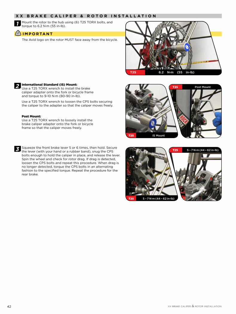
1 Mount the rotor to the hub using (6) T25 TORX bolts, and torque to 6.2 N·m (55 in-lb).
I M P O R TA N TThe Avid logo on the rotor MUST face away from the bicycle.
2 International Standard (IS) Mount:Use a T25 TORX wrench to install the brake caliper adapter onto the fork or bicycle frame and torque to 9-10 N·m (80-90 in-lb).
Use a T25 TORX wrench to loosen the CPS bolts securing the caliper to the adapter so that the caliper moves freely.
Post Mount:Use a T25 TORX wrench to loosely install the brake caliper adapter onto the fork or bicycle frame so that the caliper moves freely.
3 Squeeze the front brake lever 5 or 6 times, then hold. Secure the lever (with your hand or a rubber band), snug the CPS bolts enough to hold the caliper in place, and release the lever. Spin the wheel and check for rotor drag. If drag is detected, loosen the CPS bolts and repeat this procedure. When drag is no longer detected, torque the CPS bolts in an alternating fashion to the specified torque. Repeat the procedure for the rear brake.
T25 6.2 N·m (55 in-lb)
T25 IS Mount
T25 Post Mount
T25 5 – 7 N·m (44 – 62 in-lb)
T25 5 – 7 N·m (44 – 62 in-lb)

43 XX BRAKE LEVER OVERHAUL
X X B R A K E L E V E R O V E R H A U LAvid brake lever assemblies need to be serviced periodically to optimize braking function. If brake fluid is leaking from any area of the brake lever assembly, there may be damage or wear and tear to the internal moving parts. If your brake was filled with fluid OTHER than DOT 5.1 (such as mineral oil, DOT 4, or DOT 5), damage to all rubber and plastic internal parts may exist. If your brake was damaged in a crash, there may be damage to the lever blade and pushrod assemblies, as well as the housing assembly. Inspection and/or replacement of these parts, due to any of the above situations, will be necessary to restore proper brake function.
WA R N I N G :Avid highly recommends the use of rubber gloves when handling DOT fluids.
DOT FLUIDS WILL DAMAGE PAINTED SURFACES! If any fluid comes in contact with a painted surface (i.e. your frame) or printing on the brakes, wipe it off immediately and clean with isopropyl alcohol or water. REMOVAL OF PAINT AND/OR PRINTING BY DOT FLUID IS NOT COVERED UNDER WARRANTY!
Do not allow any brake fluid to come in contact with the brake pads. If this occurs, the pads are contaminated and must be replaced.
For best results, use only Avid Hi Performance DOT 5.1 Fluid. If Avid fluid is not available, only use DOT 5.1 fluid. Do NOT use mineral oil, DOT 5, or DOT 4 fluid.
Used DOT fluid should be recycled or disposed of in accordance to local and federal regulations.
NEVER pour used DOT fluid down a sewage or drainage system or into the ground or a body of water.
P A R T S A N D T O O L S N E E D E D F O R S E R V I C E :Safety glasses
Rubber gloves
T25 TORX™ wrench
Avid Pivot Pin Press
Oil pan
DOT 5.1 brake fluid or DOT 5.1 compatible grease
Adjustable torque wrench
8 and 11 mm open ended wrenches
2 and 5 mm hex wrenches
Bench vice or 10 mm open ended wrench
Soapy water
Clean rag
A B C
F G
D
EXPLODED VIEW - XX BRAKE LEVER ASSEMBLY
E
A. LEVER BODY B. PIVOT BUSHINGS C. PISTON/BLADDER/SNAP RING/REACH ADJUST PUSHROD ASSEMBLY
D. PIVOT PIN E. LEVER BLADE F. SNAP RING (shown removed) G. PISTON SPRING

44 XX BRAKE LEVER OVERHAUL
1 Use a T25 TORX wrench to remove the brake clamp bolt from the discreet clamp, MMX, or XLoc (XLoc will first require the removal of the XX shifter). Remove the brake lever from the handlebar. Pull the hose boot off the compression nut and slide it down the hose.
Use a T25 TORX wrench to remove the calipers from the fork or frame.
If dirty, clean the levers and calipers with soapy water and a clean rag.
2 Use an 11 mm open ended wrench to hold the hose stop in place and use an 8 mm open ended wrench to unscrew the hose compression nut. Pull the brake hose and compression fitting from the brake lever body.
XLoc
Discreet Clamp
MMX
45 XX BRAKE LEVER OVERHAUL
3 Allow any brake fluid to drain into a container. Hold lever assembly over container and squeeze the lever to pump any brake fluid from inside the lever assembly.
I M P O R TA N TIf the system has been contaminated with fluid (any fluid other than DOT 5.1 brake fluid), you will need to flush all the parts with soapy water, rinse, and allow to dry fully prior to rebuilding. You will also need to install all new seals and a new hose.
4 Use the Pivot Pin Press to remove the pivot pin from the lever:
Prepare the tool by first installing the small washer followed by the press sleeve onto the bolt.
Next, slide the bolt through pivot pin of the lever.
Thread the catcher onto the bolt until it makes contact with the lever body.
Insert the lever blade brace, with the contoured side against the pivot pin, into the lever blade.
Use a vise or 10 mm open end wrench and secure the catcher by the flat edges.
Use a 5 mm hex wrench and turn the bolt clockwise until the pivot pin is pushed into the catcher.
Remove the tool and pin from the brake lever.
5 Use a 2 mm hex wrench to turn the reach adjust pushrod clockwise until it unthreads from the pushrod pivot pin.
5 mm
2 mm

46 XX BRAKE LEVER OVERHAUL
6 Remove the lever, lever bushings, and piston spring from the lever body.
7 Clamp a 2 mm hex wrench into a vise with the long end extending upward. Install the lever body onto the wrench, with the wrench inserted into the lever body through the fluid flow port in the master cylinder head.
8 While applying light downward pressure to the lever body, use long snap ring pliers to remove the snap ring in the lever body along with the piston/bladder assembly. Remove the lever body from the hex wrench.
I M P O R TA N TThe piston/bladder assembly is attached to the snap ring.
9 Replace the entire piston/bladder/snap ring assembly with a new assembly. Lubricate the piston/bladder assembly by dipping it into DOT 5.1 fluid.
I M P O R TA N TYou can also use DOT 5.1 compatible grease as a lubricant.
2 mm

47 XX BRAKE LEVER OVERHAUL
10 Use long snap ring pliers to push the piston/bladder/snap ring assembly into the lever body, and secure the snap ring in its groove with the snap ring eyelets oriented toward the lever blade opening.
11 Install the piston spring, with the larger diameter end first, onto the reach adjust pushrod in the lever body.
12 Insert a 2 mm hex wrench through the non-stepped side of the push rod pivot pin and into the reach adjust pushrod. Place the lever blade into the opening of the lever body, then use the 2 mm hex wrench to turn the pushrod counter-clockwise and thread it into the pushrod pivot pin from the stepped side of the pin. Thread the pushrod through the pin until it is flush with the non-stepped side.
13 Slide a pivot bushing in between each side of the lever blade and the lever body. Align the holes in the lever body, both bushings, and the lever blade, then slide the press sleeve of the Pivot Pin Press into the holes to maintain alignment.
2 mm

48 XX BRAKE LEVER OVERHAUL
14 Use the Pivot Pin Press to install the pivot pin into the lever:
Prepare the tool by installing the washer and brake lever pivot pin onto the bolt.
Insert the threaded end of the bolt through the press sleeve in the lever body.
Thread the catcher, open end first, onto the bolt from the other side of the lever body.
Use a vise or 10 mm open end wrench to secure the flat end section of the catcher.
Insert the lever blade brace into the lever blade with the contoured end resting against the pivot pin.
Use a 5 mm hex wrench to turn the bolt clockwise and press the press sleeve and pivot pin into the lever body until the press sleeve separates from the lever body and drops into the catcher and the pivot pin is centered in the lever body.
Remove the tool from the brake lever.
I M P O R TA N TThe lever blade action may feel sluggish following installation of the pivot pin. To improve the feel, mount the brake lever onto the handlebar, hold the lever blade between your thumb and forefinger, then gently flex the lever blade from side to side. Check the lever pivot action. Repeat this process until the lever pivot action feels smooth. Be careful not to flex the lever too far at any time, otherwise damage to the lever blade or body could occur.
5 mm

49 XX BRAKE LEVER OVERHAUL
15 Use a T25 TORX wrench to re-install the calipers onto the fork or frame.
Slide the hose boot onto the compression nut. Re-install the brake lever into the discreet clamp, MMX, or XLoc. Use a T25 TORX wrench to re-install the brake clamp bolt into the discreet clamp, MMX, or XLoc.
See these sections of the XX Technical Manual for more detailed installation instructions:
Brake Caliper Installation
Discreet Clamp Installation
MMX Clamp Installation
XLoc Installation
2 mm
T25 5 – 6 N·m (44 – 53 in-lb)
T25 5 – 6 N·m (44 – 53 in-lb)
T25 5 – 7 N·m (44 – 62 in-lb)
T25 5 – 7 N·m (44 – 62 in-lb)
50 XX BRAKE CALIPER OVERHAUL PROCEDURE
X X B R A K E C A L I P E R O V E R H A U L P R O C E D U R E
I M P O R TA N T:Avid brake lever assemblies need to be serviced periodically in order to optimize braking function. If brake fluid is leaking from any area of the brake lever assembly, there may be damage or wear and tear to the internal moving parts. If your brake was filled with fluid OTHER than DOT 4 or 5.1 (such as mineral oil or DOT 5), damage to all rubber and plastic internal parts may exist. If your brake was damaged in a crash, there may be damage to the lever blade and pushrod assemblies, as well as the housing assembly. Inspection and/or replacement of these parts, due to any of the above situations, will be necessary to restore proper brake function.
WA R N I N G :Avid highly recommends the use of rubber gloves when handling DOT fluids.
DOT FLUIDS WILL DAMAGE PAINTED SURFACES! If any fluid comes in contact with a painted surface (i.e. your frame) or printing on the brakes, wipe it off immediately and clean with isopropyl alcohol or water. REMOVAL OF PAINT AND/OR PRINTING BY DOT FLUID IS NOT COVERED UNDER WARRANTY!
Do not allow any brake fluid to come in contact with the brake pads. If this occurs, the pads are contaminated and must be replaced.
For best results, use only Avid Hi Performance DOT Fluid. If Avid fluid is not available, only use DOT 5.1 fluid. Do NOT use mineral oil.
Used DOT fluid should be recycled or disposed of in accordance to local and federal regulations.
NEVER pour used DOT fluid down a sewage or drainage system or into the ground or a body of water.
P A R T S A N D T O O L S N E E D E D F O R S E R V I C E :Safety glasses
Gloves
T30, T25, and T10 TORX® wrenches
DOT compatible grease
Oil pan
Snap ring pliers
Flathead screwdriver
Air compressor with blow gun chuck
Adjustable torque wrench
4 mm hex wrench
8 mm and 11 mm open ended wrench
Sharp pick
Clean rags
Needle-nosed pliers
T R O U B L E S H O O T I N G‘Sticky’ or slow brake pad return feelBefore completely disassembling your caliper, it’s worth trying to loosen the sticky piston. Try the following:
Clamp the bicycle in a bicycle work stand. 1.
Spin the affected wheel. Lightly squeeze the brake lever and watch the brake pads when the lever is released. 2.
Determine which side of the caliper has a slow returning brake piston.3.
Remove the caliper from the bicycle. If you have a caliper mounting bracket, remove the bracket with the caliper attached.4.
Remove e-clip from the guide pin groove on top of the caliper. Use a 2.5 mm hex wrench to remove the guide pin from the 5. caliper.
Remove both brake pads and h-spring. 6.
Use a 10 mm box wrench to press the working piston into caliper body. 7.
Squeeze the brake lever slowly to move the sticky piston inward. Press the piston back into the caliper again.8.
Repeat these steps to correct caliper piston inner o-ring position. 9.
Both pistons should now be moving freely. Re-install the spring pad clip, h-spring, and pads into the caliper. If there is no 10. improvement, continue with caliper service.
Re-install the caliper (or mounting bracket with attached caliper) on the bicycle. You may need to re-center the caliper to the 11. rotor. If you removed the caliper without an adapter, or removed it from the adapter, it will need to be re-centered. Spin the wheel and check brake function.

51 XX BRAKE CALIPER OVERHAUL PROCEDURE
1 Use a T25 TORX wrench to remove the brake caliper from the fork or frame and remove the caliper mounting bracket and CPS hardware from the caliper. Set aside in the correct order (not pictured).
2 Remove the e-clip from the guide pin groove on top of the caliper. Use a 2.5 mm hex wrench to remove the guide pin from the caliper.
3 Pull and remove both brake pads and h-spring.
I M P O R TA N T:If the total thickness of the backing plate and pad friction material is less than 3 mm, the brake pads need to be replaced.
4 Use an 8 mm open-ended wrench to loosen the banjo bolt. Brake fluid will leak, so hold the hose over a container to catch fluid.
5 Pull the banjo bolt completely out of caliper. Dump all caliper brake fluid into a container.

52 XX BRAKE CALIPER OVERHAUL PROCEDURE
6 Use a T10 TORX to remove the bleed screw from the banjo bolt.
7 Use a sharp pick to remove the bleed screw o-ring. This o-ring may be a little hard to see. Replace with a new bleed screw o-ring.
8 Re-install the banjo bolt bleed screw into the banjo bolt and tighten with a T10 TORX.
9 Remove and replace the o-rings on banjo the bolt and banjo.

53 XX BRAKE CALIPER OVERHAUL PROCEDURE
10 Use a T25 TORX to loosen and remove the caliper body bolt.
11 Separate the caliper body halves and open the caliper assembly.
12 Using a sharp pick, remove the small banjo hole (body half) o-ring.
13 Caliper Piston Removal:Using an air compressor chuck, insert the chuck nozzle into the banjo bolt hole of one of the caliper body halves.
Hold the caliper in one hand and point the caliper piston in a safe direction. Hold one finger over the banjo bolt through-hole on opposite side of caliper body so air does not escape.
Squeeze the air chuck and force air into the banjo bolt hole. The compressed air will unseat the piston from the caliper. Remove the piston from the caliper.
WA R N I N G :Point the caliper in a safe direction. Use a cloth or a plastic bag to prevent the piston from causing injury or becoming lost. Repeat this process for the other caliper body half.Repeat this process for the other caliper body half.

54 XX BRAKE CALIPER OVERHAUL PROCEDURE
14 Remove the square-edge o-ring from inside each caliper body half with a sharp pick and replace with new square-edge o-rings.
15 Inspect the caliper pistons for damage and replace if necessary. Re-install the caliper brake pistons into each half of the caliper body. Make sure the piston slots are vertical in the caliper body. (this keeps the fluid slots on the back side of piston lined up with fluid ports).
16 Use a sharp pick to remove and replace the outboard caliper body o-ring.
17 Re-assemble the two caliper body halves. Use a T25 TORX to loosely re-install the caliper body bolt to hold the assembly together.
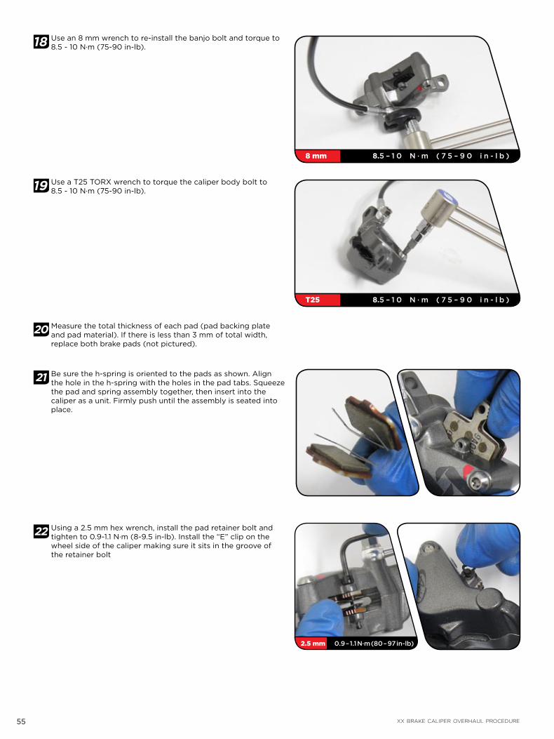
55 XX BRAKE CALIPER OVERHAUL PROCEDURE
18 Use an 8 mm wrench to re-install the banjo bolt and torque to 8.5 - 10 N·m (75-90 in-lb).
19 Use a T25 TORX wrench to torque the caliper body bolt to 8.5 - 10 N·m (75-90 in-lb).
20 Measure the total thickness of each pad (pad backing plate and pad material). If there is less than 3 mm of total width, replace both brake pads (not pictured).
21 Be sure the h-spring is oriented to the pads as shown. Align the hole in the h-spring with the holes in the pad tabs. Squeeze the pad and spring assembly together, then insert into the caliper as a unit. Firmly push until the assembly is seated into place.
22 Using a 2.5 mm hex wrench, install the pad retainer bolt and tighten to 0.9-1.1 N·m (8-9.5 in-lb). Install the “E” clip on the wheel side of the caliper making sure it sits in the groove of the retainer bolt
8 mm 8.5 – 1 0 N · m ( 7 5 – 9 0 i n - l b )
T25 8.5 – 1 0 N · m ( 7 5 – 9 0 i n - l b )
2.5 mm 0.9 – 1.1 N·m (80 – 97 in-lb)

56 XX BRAKE CALIPER OVERHAUL PROCEDURE
23 Visually check your work. Inspect the banjo bolt and banjo for any protruding o-rings. If there are any o-rings that are ‘squeezed’ beyond the outside edges of the banjo or bolt, remove and replace the o-rings, and then repeat the installation process.
24 Use a T25 TORX wrench to re-install the calipers onto the fork or frame. Wipe assembled the caliper with soapy water to remove any brake fluid. Re-install the caliper onto the bicycle following the installation procedure and torque specifications called out in the user manual.
See this section of the XX Technical Manual for more detailed installation instructions:
Brake Calipers
T25 5-7 N·m (44-62 in-lb)
T25 9-10 N·m (80-90 in-lb)

57 XX BRAKE HOSE LENGTH ADJUSTMENT
X X B R A K E H O S E L E N G T H A D J U S T M E N T
WA R N I N G :Avid highly recommends the use of rubber gloves when handling DOT fluids.
DOT FLUIDS WILL DAMAGE PAINTED SURFACES! If any fluid comes in contact with a painted surface (i.e. your frame) or printing on the brakes, wipe it off immediately and clean with isopropyl alcohol or water. REMOVAL OF PAINT AND/OR PRINTING BY DOT FLUID IS NOT COVERED UNDER WARRANTY!
Do not allow any brake fluid to come in contact with the brake pads. If this occurs, the pads are contaminated and must be replaced.
For best results, use only Avid Hi Performance DOT Fluid. If Avid fluid is not available, only use DOT 5.1 fluid. Do NOT use mineral oil.
Used DOT fluid should be recycled or disposed of in accordance to local and federal regulations.
NEVER pour used DOT fluid down a sewage or drainage system or into the ground or a body of water.
P A R T S A N D T O O L S N E E D E D F O R S E R V I C E :Safety glasses
Gloves
Hydraulic hose cutters or very sharp cable-housing cutters
DOT compatible grease
Isopropyl alcohol
Avid Bleed Kit
Adjustable torque wrench
8 and 11 mm open ended wrenches
Towels
Avid Hi-Performance DOT 5.1 Fluid
Avid Bleed Kit Contents
Avid Hi-Performance DOT Fluid
TORX wrench
Hose barbs
Compression fittings
Syringes
Bleed Block(actual bleed block
may di!er)
1 Take a moment and check the routing of the hoses since you can’t lengthen the hose once you have cut it. Be sure to account for suspension movement and check that the bars turn freely by turning the bars all the way from side to side. Make sure the hoses are properly secured as well.

58 XX BRAKE HOSE LENGTH ADJUSTMENT
2 Pull the boot away from the lever to access the compression nut. If the boot sticks, carefully pry up a corner with something that won’t harm it (like the end of a zip tie) and spray isopropyl alcohol between the boot and the lever. Work the alcohol in; the boot should loosen up and slide easily down the hose.
3 Use an 11 mm open ended wrench to hold the hose stop in place, and use an 8 mm open ended wrench to unscrew the hose compression nut.
4 Pull the hose from the lever, wiggling it if necessary. Be careful, DOT fluid will drip from the hose. Try not to spill too much fluid because any fluid that drips out will create bubbles that you’ll have to eliminate later.
Slide the nut down the hose and away from the end where you’ll be cutting. Do not pull the brake lever while the hose is removed.
5 Determine where you need to cut the hose by holding it up to the lever in the position you like. Make sure to leave a gentle bend in the hose with enough length to freely turn the bars all the way from side to side. Double-check this measurement because you can’t go back after you cut.
6 The groove in the lever nose marks the spot where you’ll cut the hose. Cut the hose using hydraulic hose cutters or very sharp cable housing cutters.

59 XX BRAKE HOSE LENGTH ADJUSTMENT
7 Apply DOT compatible grease to the threads of a new hose barb, the compression fitting outer surfaces and compression nut threads.
8 While holding the hose firmly, thread the hosebarb into the end of the hose using a T10 TORX.
9 Slide a new compression fitting over the end of the hose with the new hose barb.
Push the hose firmly into the lever until it stops.
While holding the hose in place, slide the compression fitting and compression nut up to the lever or hose stop.
10 While continuing to push the hose into the hose stop, use an 11 mm open ended wrench to hold the hose stop in place and use an 8 mm open ended wrench to torque the compression nut to 5 N·m (47 in-lb).
11 Slide the boot back into place.
I M P O R TA N T:Cutting the hose introduces a small amount of air into the system, so at this point it is necessary to bleed the brakes for optimal performance. See the next section, “XX Brake Bleed Procedure” for instructions.

60 XX BRAKE BLEED PROCEDURE
X X B R A K E B L E E D P R O C E D U R EAvid brakes are the most powerful and precise hydraulic brakes on the market. A key reason behind this is the ability to optimize brake performance with a perfect bleed. The goal of bleeding is to remove any air that is trapped in the hose, caliper, or lever. Air trapped in a hydraulic brake system degrades the performance of the brake. The following instructions will walk you through our simple bleed procedure.
I M P O R TA N T:XX brakes come with hoses attached and bled. If you don’t need to change the hose length, you do not need to bleed the system prior to installation.
WA R N I N G :Avid highly recommends the use of rubber gloves when handling DOT fluids.
DOT FLUIDS WILL DAMAGE PAINTED SURFACES! If any fluid comes in contact with a painted surface (i.e. your frame) or printing on the brakes, wipe it off immediately and clean with isopropyl alcohol or water. REMOVAL OF PAINT AND/OR PRINTING BY DOT FLUID IS NOT COVERED UNDER WARRANTY!
Do not allow any brake fluid to come in contact with the brake pads. If this occurs, the pads are contaminated and must be replaced.
For best results, use only Avid Hi Performance DOT Fluid. If Avid fluid is not available, only use DOT 5.1 fluid. Do NOT use mineral oil.
Used DOT fluid should be recycled or disposed of in accordance to local and federal regulations.
NEVER pour used DOT fluid down a sewage or drainage system or into the ground or a body of water.
P A R T S A N D T O O L S N E E D E D F O R S E R V I C E :Safety glasses
Gloves
T25 and T10 TORX® wrenches
Hydraulic hose cutters or very sharp cable-housing cutters
DOT compatible grease
Isopropyl alcohol
Avid Bleed Kit
Adjustable torque wrench
Avid Bleed Block
2.5 and 4 mm hex wrenches
Sharp pick
Towels
Avid Hi-Performance DOT 5.1 Fluid
Avid Bleed Kit Contents
Avid Hi-Performance DOT Fluid
TORX wrench
Hose barbs
Compression fittings
Syringes
Bleed Block(actual bleed block
may di!er)
I M P O R TA N T:When bleeding Avid brakes, keep in mind that you are simply chasing bubbles out of the system. Avid recommends that you bleed your brakes at least once a year to ensure optimal performance. If you ride frequently or in aggressive terrain, you should bleed your brakes more often.
When bleeding brakes, you may notice discoloration of the old fluid as it exits the system into the syringe at the lever. If the fluid is severely discolored, this indicates that the fluid is very old. In this case, bleeding the system twice in order to completely remove the old fluid is recommended.

61 XX BRAKE BLEED PROCEDURE
1 Fill one syringe 1/2 full with Avid Hi-Performance DOT Fluid and fill the other syringe 1/4 full.
Hold each syringe with the tip pointed up and tap the side of the syringe with your finger to bring any air bubbles to the top. Place a towel around the tip and slowly push the air bubbles out of the syringe. Close the hose clamp on each syringe.
2 Take a moment to de-gas the fluid in the 1/2 full syringe. Leave the hose clamp shut and pull on the plunger. Bubbles will form in the brake fluid. While the plunger is still pulled down, lightly tap the syringe to release the bubbles sticking to the sides and the bottom so that they can rise to the top of the fluid. When the bubbles stop forming and have all risen to the top, release the plunger, open the clamp and carefully push the air out. Repeat several times.
I M P O R TA N T:You will not be able to remove all the bubbles.
3 Remove the wheel from your bike.
1 Use a small screwdriver or pick to remove the “E” clip from the caliper, then use a 2.5 mm hex wrench to unscrew and remove the retainer bolt.
3 Remove the brake pads and spreader clip from the caliper and insert the appropriate Bleed Block. This will help prevent system overfill and keep DOT fluid from contaminating your brake pads.
Click here for detailed brake pad removal instructions
2.5 mm

62 XX BRAKE BLEED PROCEDURE
4 Use the T10 TORX to remove the caliper bleed port screw from the banjo bolt
5 Make sure the fluid in the 1/2 full syringe is pushed all the way to the tip (no air gap!), then thread into the caliper bleed port.
6 Ensure that the reach is not adjusted so far out that it causes the lever blade to bottom out on the lever body. Doing so can make bleeding the brake impossible. Use a 2 mm hex wrench to adjust the position of the brake lever.
7 Rotate the pad contact adjuster in the direction opposite the arrow on the adjuster knob, until it stops. Then rotate the adjuster back just enough to place the bleed screw at its highest point.

63 XX BRAKE BLEED PROCEDURE
8 Use the T10 TORX to remove the lever bleed port screw.
9 Make sure the fluid in the 1/4 full syringe is pushed all the way to the tip (no air gap!), then thread into the lever bleed port.
I M P O R TA N T:It is not necessary to reposition the angle of the brake lever on the handlebar. You may have a small amount of DOT fluid drip from the bleed port screw, this is normal. Just have a towel handy to wipe off any excess after the syringe is installed.
10 Hold the caliper syringe upright in your right hand and the lever syringe upright in your left hand.
Gently push on the caliper syringe plunger to move fluid from the caliper syringe into the lever syringe until the lever syringe is increased to 1/2 full and the caliper syringe is decreased to 1/4 full.
I M P O R TA N T:You should see bubbles form in the lever syringe.
11 Close the red syringe clamp on the lever.
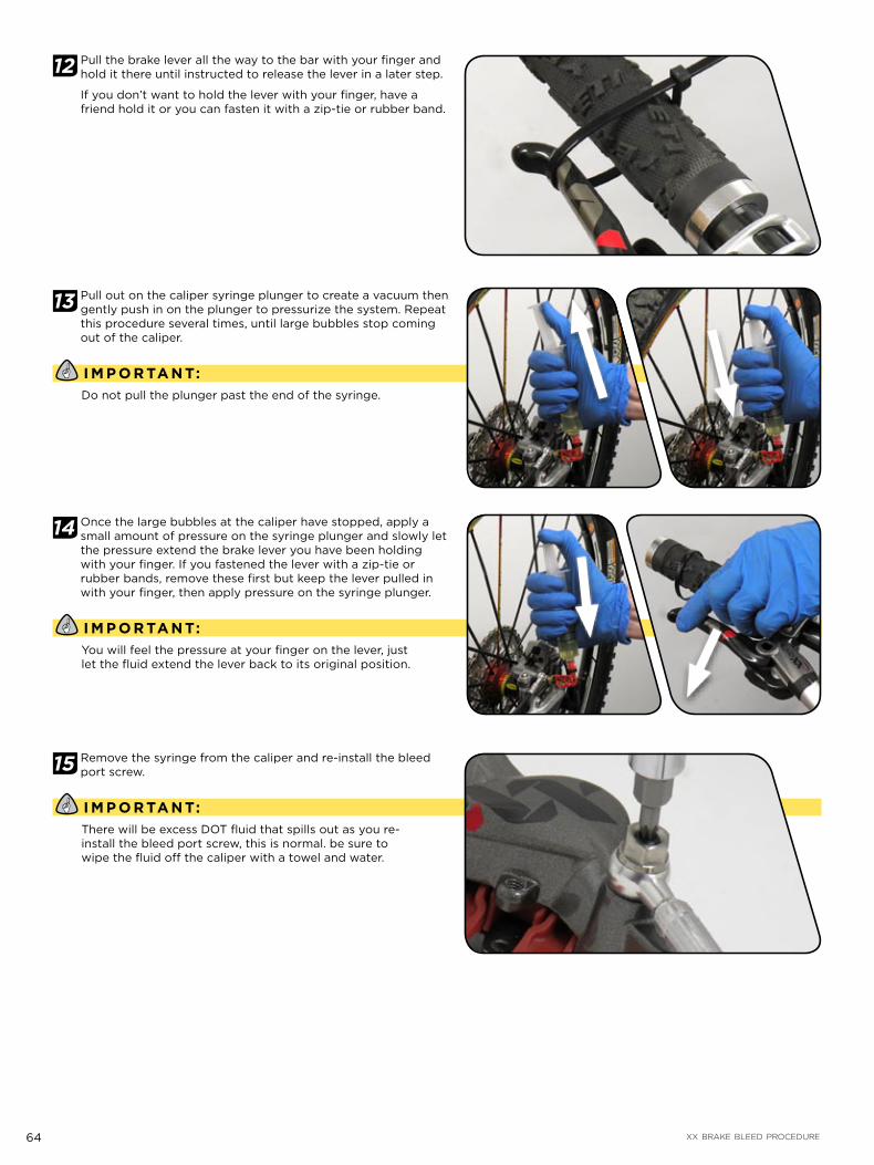
64 XX BRAKE BLEED PROCEDURE
12 Pull the brake lever all the way to the bar with your finger and hold it there until instructed to release the lever in a later step.
If you don’t want to hold the lever with your finger, have a friend hold it or you can fasten it with a zip-tie or rubber band.
13 Pull out on the caliper syringe plunger to create a vacuum then gently push in on the plunger to pressurize the system. Repeat this procedure several times, until large bubbles stop coming out of the caliper.
I M P O R TA N T:Do not pull the plunger past the end of the syringe.
14 Once the large bubbles at the caliper have stopped, apply a small amount of pressure on the syringe plunger and slowly let the pressure extend the brake lever you have been holding with your finger. If you fastened the lever with a zip-tie or rubber bands, remove these first but keep the lever pulled in with your finger, then apply pressure on the syringe plunger.
I M P O R TA N T:You will feel the pressure at your finger on the lever, just let the fluid extend the lever back to its original position.
15 Remove the syringe from the caliper and re-install the bleed port screw.
I M P O R TA N T:There will be excess DOT fluid that spills out as you re-install the bleed port screw, this is normal. be sure to wipe the fluid off the caliper with a towel and water.

65 XX BRAKE BLEED PROCEDURE
16 Open the red syringe clamp on the lever.
17 Pull out on the lever syringe plunger to create a vacuum, then gently push in on plunger to pressurize the system. Squeeze and release the brake lever ten times, allowing the lever to snap back to its starting position after squeezing (this helps break loose the bubbles). Repeat this procedure of creating a vacuum at the syringe and squeezing the brake lever ten times until large bubbles stop coming out of the lever.
I M P O R TA N T:Be careful not pull out too hard on the plunger or you will suck air past the plunger seal into the fluid and create more bubbles that you will have to eliminate.
18 Once the large bubbles at the lever have stopped, apply a small amount of pressure on the syringe plunger then remove the syringe and re-install the bleed port screw.
I M P O R TA N T:There will be a small amount of excess DOT fluid that spills out as you remove the syringe and re-install the bleed port screw, this is normal. be sure to wipe the fluid off the lever with a towel.

66 XX BRAKE BLEED PROCEDURE
19 Spray isopropyl alcohol or water onto a towel and wipe off the brake lever and caliper to remove any excess DOT fluid.
20 Remove the Bleed Block from the caliper and re-install the brake pads and spreader clip.
Click here for detailed brake pad re-installation instructions
6 Install the pad retainer bolt and use a 2.5 mm hex wrench to torque to 0.9-1.1 N·m (80-97 in-lb). Install the “E” clip on the wheel side of the caliper making sure it sits in the groove of the retainer bolt.
21 Re-install your wheel according to the manufacturer’s instructions.
WA R N I N G :Empty the syringes into a sealed container and dispose of the fluid properly. Remember, used DOT fluid should be recycled or disposed of in accordance to local and federal regulations. NEVER pour used DOT fluid down a sewage or drainage system or into the ground or a body of water.Do not re-use this fluid.Do not leave the hose clamps closed, this will damage the clear tubing on the syringes.
22 You are almost ready to ride, but first it’s a good idea to test your brakes. Pull on the lever extremely hard (as hard as you can imagine yourself pulling the lever while you’re riding) several times. Make sure and look around the hose nut on the lever, and the banjo bolt on the caliper for any leaks. Make one last check of all the bolts and fittings.If everything checks out, YOU ARE READY TO RIDE!
2.5 mm 0.9 – 1.1 N·m (80 – 97 in-lb)

67 DISC BRAKE PAD REPLACEMENT PROCEDURE
D I S C B R A K E P A D R E P L A C E M E N T P R O C E D U R EAvid brake pads should be replaced when the total thickness of the backing plate and pad friction material is less than 3 mm. Replacing worn brake pads will improve braking performance. New brake pads are subject to a “wear-in” period. It may take anywhere from 20 to 40 complete stops to wear in Avid pads. You may begin to notice an increase in braking power after the first ride. Brake noise can occur during the wear-in period, as well as off and on throughout the life of the brake pads. This is normal and should not affect braking performance. Noise is dependent upon factors such as brake setup, rider weight, riding style, braking style, and riding conditions (i.e. dust, soil, and contamination of friction surfaces).
WA R N I N G :XX brakes are compatible only with Avid organic brake pads.
1 Use a small screwdriver or pick to remove the “E” clip from the caliper, then use a 2.5 mm hex wrench to unscrew and remove the retainer bolt.
2 Grab the pad tabs and pull straight out.
3 XX brake caliper pistons need to be pushed back into the caliper body before the new pads can be installed. Insert a large box-wrench (or similar tool without sharp edges) between the pistons, then carefully rock it back and forth, pushing the pistons back into their bores.
4 Inspect and measure the total thickness of each brake pad with a ruler. If the total thickness is less than 3 mm, you need to replace both brake pads (not pictured).
T I P S A N D T R I C K Sif the backing plate and pad material is thicker than 3 mm, you can simply re-install your brake pads as outlined in step 5.
2.5 mm
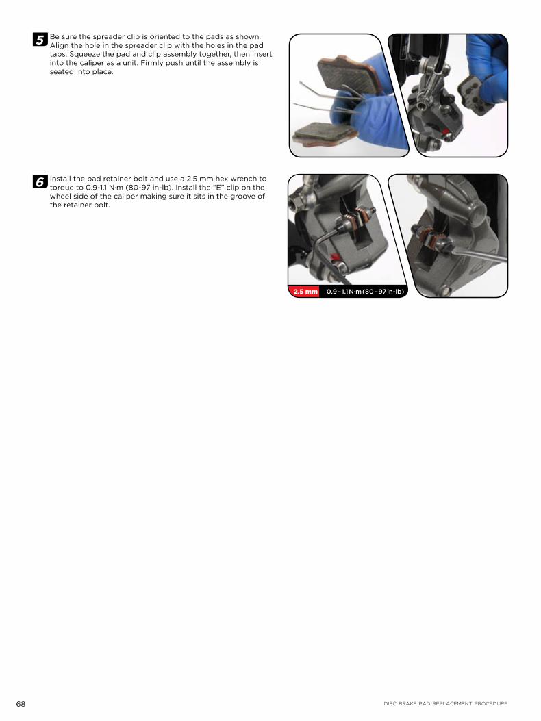
68 DISC BRAKE PAD REPLACEMENT PROCEDURE
5 Be sure the spreader clip is oriented to the pads as shown. Align the hole in the spreader clip with the holes in the pad tabs. Squeeze the pad and clip assembly together, then insert into the caliper as a unit. Firmly push until the assembly is seated into place.
6 Install the pad retainer bolt and use a 2.5 mm hex wrench to torque to 0.9-1.1 N·m (80-97 in-lb). Install the “E” clip on the wheel side of the caliper making sure it sits in the groove of the retainer bolt.
2.5 mm 0.9 – 1.1 N·m (80 – 97 in-lb)
69 DISC BRAKE PAD AND ROTOR BED-IN PROCEDURE
D I S C B R A K E P A D A N D R O T O R B E D - I N P R O C E D U R EAll new brake pads and rotors should be put through a wear-in process called ‘bed-in’. The bed-in procedure, which should be performed prior to your first ride, ensures the most consistent and powerful braking feel along with the quietest braking in most riding conditions. The bed-in process heats up the brake pads and rotors which deposits an even layer of brake pad material (transfer layer) to the braking surface of the rotor. It this transfer layer that optimizes braking performance.
WA R N I N G :THE BED-IN PROCESS REQUIRES YOU TO PERFORM HEAVY BRAKING. YOU MUST BE FAMILIAR WITH THE POWER AND OPERATION OF DISC BRAKES. BRAKING HEAVILY WHEN NOT FAMILIAR WITH THE POWER AND OPERATION OF DISC BRAKES COULD CAUSE YOU TO LOSE CONTROL OF YOUR BICYCLE WHICH COULD LEAD TO A CRASH WHICH COULD LEAD TO SERIOUS INJURY AND/OR DEATH. IF YOU ARE UNFAMILIAR WITH THE POWER AND OPERATION OF DISC BRAKES YOU SHOULD HAVE THE BED-IN PROCESS PERFORMED BY A QUALIFIED BICYCLE MECHANIC.
I M P O R TA N T:To safely achieve optimal results, remain seated on the bike during the entire bed-in procedure.
1 Accelerate the bike to a moderate speed, then firmly apply the brakes until you are at walking speed. Repeat approximately twenty times.
2 Accelerate the bike to a faster speed. Then very firmly apply the brakes until you are at walking speed. Repeat approximately ten times.
I M P O R TA N T:Do not lock up the wheels at any point during the bed-in procedure.
3 Allow the brakes to cool prior to any additional riding.
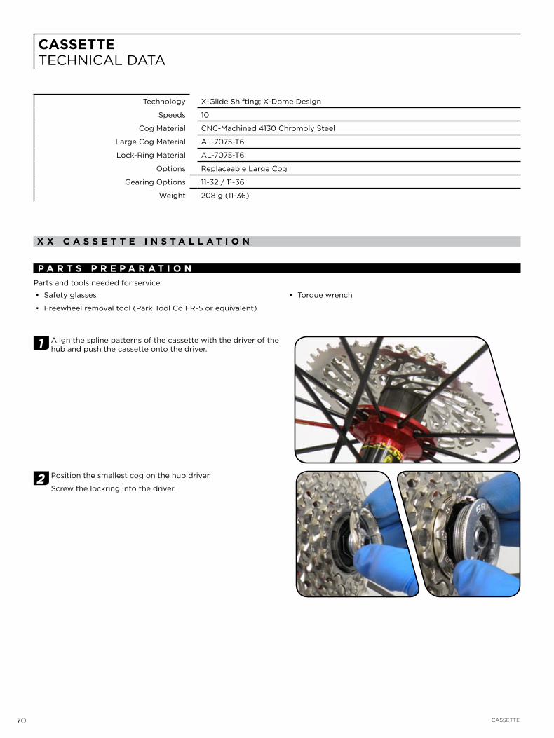
70 CASSETTE
CASSETTETECHNICAL DATA
Technology X-Glide Shifting; X-Dome Design
Speeds 10
Cog Material CNC-Machined 4130 Chromoly Steel
Large Cog Material AL-7075-T6
Lock-Ring Material AL-7075-T6
Options Replaceable Large Cog
Gearing Options 11-32 / 11-36
Weight 208 g (11-36)
X X C A S S E T T E I N S T A L L A T I O N
P A R T S P R E P A R A T I O NParts and tools needed for service:
Safety glasses
Freewheel removal tool (Park Tool Co FR-5 or equivalent)
Torque wrench
1 Align the spline patterns of the cassette with the driver of the hub and push the cassette onto the driver.
2 Position the smallest cog on the hub driver.
Screw the lockring into the driver.

71 XLOC
2 Use a freewheel tool (Park Tool® FR-5 or equivalent) and a torque wrench to tighten the cassette lockring to 40 N·m (350 in-lb).
I M P O R TA N T:Be careful not to damage the thread of the lockring by tilting.
See the REAR DERAILLEUR section for indexed shifting setup.
R E M O V A L
2 Insert a freewheel tool (Park Tool Co FR-5 or equivalent) into the splines of the lockring. Use a chain wrench (chain whip) to hold the cassette in place while turning the freewheel tool with a large wrench counter-clockwise to loosen the lockring.
M A I N T E N A N C E
I M P O R TA N T:The thin aluminum tube captured inside the XX cassette is designed to have a small amount of movement before installation. After installation, the aluminum tube is squeezed between the cogs and the aluminum backing plate and forms a water-tight seal. The tube also provides structural reinforcement to the entire cassette - do not remove!
C AU TI O N :Do not use acid cleaner on the cogs! They will get brittle and can break under heavy load. Use a bio-degradable cleaner such
Do not soak or store the cogs in any cleaning product. This can lead to corrosion.
If the XX cassette is washed while not installed on a hub, water can be trapped in the cassette between the cogs and the aluminum tube. Use compressed air to drive out any water.

72 XLOC
XLOCTECHNICAL DATA
Material AL-7075-T6
Hydraulic Fluid 5wt suspension fluid; SRAM Pit Stop™ suspension fluid recommended
Hardware Titanium
Options Left / Right side options; Matchmaker X compatible
X L O C H O S E L E N G T H A D J U S T M E N T
C AU TI O N :The XLoc damper remote lockout uses a specific hydraulic hose that is compatible with the system’s suspension fluid.
Do NOT use hydraulic brake hose to replace the XLoc hydraulic hose. Only use XLoc compatible hydraulic hose.
Do NOT use hydraulic brake fluid or mineral oil in the XLoc system. Only use 5wt suspension fluid.
Do NOT use hydraulic brake bleed tools to bleed the XLoc system. Only use the RockShox Speed Lube Kit.
I M P O R TA N T:Always wear safety glasses and rubber gloves when working with suspension fluid.
P A R T S P R E P A R A T I O NParts and tools needed for service:
Safety glasses
Rubber Gloves
Replacement XLoc hydraulic hose
Hydraulic hose cutter or cable housing cutter
Sharp knife
Oil pan
1 To reduce the hydraulic hose length: Use a sharp knife to carefully cut a 1 cm slit in the hydraulic hose across the top of the hose barb at the XLoc remote.
I M P O R TA N T:Do not scratch the hose barb. Scratches on the hose barb can cause the XLoc remote to leak.
Pull the cut end of the hydraulic hose from the hose barb.
Use a hydraulic hose cutter or sharp cable housing cutter to cut the hydraulic hose to the desired length.
Firmly press the hydraulic hose back onto the hose barb until the hose bottoms out.
Bleed your XLoc according to the XLoc bleed procedure.
Hose Barb

73 XLOC HOSE LENGTH ADJUSTMENT
2 To increase the hydraulic hose length: Use a sharp knife to carefully cut a slit in the hydraulic hose across the top of the hose barb at the fork crown and the hose barb at the XLoc. Do not scratch the hose barbs.
I M P O R TA N T:Do not scratch the hose barb. Scratches on the hose barb can cause the XLoc remote to leak.
Pull the hydraulic hose from the hose barbs and discard.
Use a hydraulic hose cutter or sharp cable housing cutter to cut the new hydraulic hose to the desired length.
Firmly press the new hydraulic hose back onto both hose barbs until the hose bottoms out.
Bleed your XLoc according to the XLoc bleed procedure.
Hose Barb
Hose Barb

74 XLOC BLEED PROCEDURE
X L O C B L E E D P R O C E D U R E
I M P O R TA N T:Always wear safety glasses and rubber gloves when working with suspension fluid.
P A R T S P R E P A R A T I O NParts and tools needed for service:
Safety glasses
Rubber Gloves
T25, T10 TORX® wrenches
Torque wrench
SRAM Pit Stop 5wt suspension fluid
RockShox Speed Lube Kit
1 Use a T25 TORX wrench to unthread the shifter mounting bolt and remove the shifter.
2 Use a T25 TORX wrench to loosen the XLoc handlebar clamp, position the XLoc so that the bleed screw is slightly above the button, and re-tighten the clamp bolt.
3 Press the XLoc button to set it to the ‘Locked’ position (button fully extended). Turn the gold Floodgate adjuster in the direction of the the arrow until it stops (maximum Floodgate).
Bleed screw

75 XLOC BLEED PROCEDURE
4 Assemble two RockShox Speed Lube Kit syringes:
Install an o-ring onto the end of the brass fitting. Insert the brass fitting into the plastic tube. Insert the red fitting into the other end of the plastic tube. Thread the red fitting into the syringe.
5 Use a T10 TORX wrench to remove the bleed screw from the top of the damper, located at the fork crown.
6 Fill both Speed Lube syringes with 10 ml of 5wt suspension fluid.
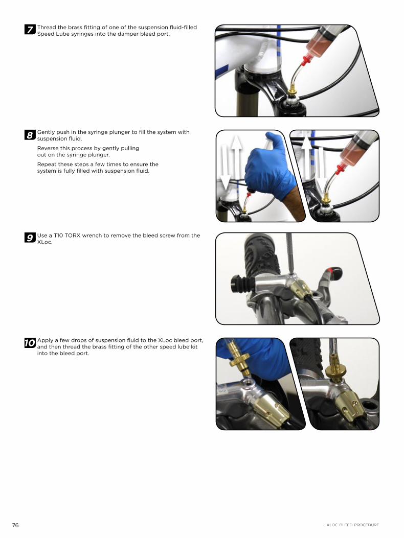
76 XLOC BLEED PROCEDURE
7 Thread the brass fitting of one of the suspension fluid-filled Speed Lube syringes into the damper bleed port.
8 Gently push in the syringe plunger to fill the system with suspension fluid.
Reverse this process by gently pulling out on the syringe plunger.
Repeat these steps a few times to ensure the system is fully filled with suspension fluid.
9 Use a T10 TORX wrench to remove the bleed screw from the XLoc.
10 Apply a few drops of suspension fluid to the XLoc bleed port, and then thread the brass fitting of the other speed lube kit into the bleed port.

77 XLOC BLEED PROCEDURE
11 Hold both syringes upright and depress the plunger of the damper syringe while simultaneously pulling out on the plunger of the remote syringe. Reverse this process and repeat until no more bubbles move into the remote syringe.
12 Unthread the syringe from the damper, and use a T10 TORX wrench to re-install the bleed screw into the damper. Use a rag to wipe off any excess suspension fluid.
13 Hold the XLoc button in the extended (locked) position and pull out the syringe plunger. Small bubbles will move into the suspension fluid as air is pulled from the system.
14 Continue pulling out on the Speed Lube syringe plunger. Push in the XLoc button to the unlocked position. This will dislodge more bubbles from the remote into the syringe.

78 XLOC BLEED PROCEDURE
15 Push in on the syringe plunger, and then press in the XLoc button to release it to the locked position. t
16 Repeat steps 13-15 until air bubbles no longer move into the suspension fluid. It can take several repetitions of this process to fully void the system of air.
17 Unthread the Speed Lube fitting from the XLoc bleed port. Put a few drops of suspension fluid into the bleed port. Replace the bleed port screw and use a T10 TORX wrench to torque to 0.5–0.7 N·m (4.5–6 in-lb). Use a rag to wipe off any excess suspension fluid.
18 Use a T25 TORX wrench to loosen the XLoc handlebar clamp. Re-position the XLoc to your desired angle. Use a T25 TORX wrench to torque the XLoc clamp bolt to 5–6 N·m (44–53 in-lb).
19 Attach the XLoc shifter to the XLoc bracket with the shifter mounting bolt. Use a T25 TORX wrench to torque the shifter mounting bolt to 2.8-3.4 N·m (25-30 in-lb).
T10 0.5 – 0.7 N·m (4.5 – 6 in-lb)
T25 5 – 6 N · m ( 4 4 – 5 3 i n - l b )
T25 2 . 8 – 3 . 4 N · m ( 2 5 – 3 0 i n - l b )

79 XLOC BLEED PROCEDURE
F R O N T S U S P E N S I O N T O O L S N E E D E D F O R S E R V I C E The following chart is a list of the tools needed for service on your model year 2010 RockShox XX front suspension. While this chart is intended to be comprehensive, it is still only a guide. The tools required for each step of service are detailed in the text of each service section. Keep in mind your specific fork may not require every tool listed.
TOOLSLOWER LEG REMOVAL
SEAL SERVICE
DAMPER SERVICE
SPRING SERVICE
LOWER LEG INSTALLATION
SAFETY/STARTING EQUIPMENT
SAFETY GLASSES X X X X X
APRON X X X X X
RUBBER GLOVES X X X X X
CLEAN RAGS (LINT FREE) X X X X X
OIL PAN X X X X X
CLEAN WORK AREA X X X X X
BICYCLE STAND X X X X
WRENCHES/PLIERS
5 mm HEX X X
10 mm SOCKET OR OPEN END WRENCH X X
15 mm SOCKET X
24 mm SOCKET X X
SOCKET EXTENSION X X X
24 mm FLAT WRENCH OR MISSION CONTROL WRENCH X
TORQUE WRENCH X X
SNAP RING PLIERS - INTERNAL X X
SNAP RING PLIERS - EXTERNAL X X
MISC TOOLS
PLASTIC MALLET X X X X X
LONG DOWEL ROD (PLASTIC OR WOOD)* X X X X X
FLATHEAD SCREWDRIVER X X
32 mm, SEAL INSTALLER X
SHARP PICK X X
SHOCK PUMP X X
MAGNET X* using a non-metallic dowel rod helps to ensure the inside of upper tubes or lower legs do not get scratched
TOOLSLOWER LEG REMOVAL
SEAL SERVICE
DAMPER SERVICE
SPRING SERVICE
LOWER LEG INSTALLATION
5, 15wt Pit-Stop SUSPENSION FLUID X X X X
GREASE (SUSPENSION FLUID SOLUBLE) X X X X
CLEAN RAGS (LINT FREE) X X X X X
OIL MEASURING DEVICE X X X X
ISOPROPYL ALCOHOL X X X X X
FROSTY COLD BEVERAGE X

80 XLOC BLEED PROCEDURE
F R O N T S U S P E N S I O N T E C H N O L O G Y A N D O I L V O L U M E S
Damper technology (drive side)
Volume (ml) Oil wt Volume
(ml) Oil wt Spring technology
(non-drive side)
Volume (ml) Oil wt Volume
(ml) Oil wt
Upper tube Lower leg Upper tube Lower leg
Reb
a X
X
XX Motion Control 123 5 5 15 Dual Air Grease 5 15
Rev
elat
ion
XX
XX Motion Control 123 5 5 15 Air U-Turn Grease 5 15
Rev
elat
ion
XX
XX Motion Control 123 5 5 15 Dual Air Grease 5 15
SID
XX
XX Motion Control 94 5 5 15 Dual Air Grease 5 15
T O R Q U E S P E C I F I C A T I O N S
FRONT SUSPENSION FASTENER TORQUE VALUE N·m (in-lb)
TOP CAPS (EXCEPT AIR U-TURN) 7.3 N·m (65 (in-lb)
BOTTOM BOLT (DAMPER SIDE) 6.8 N·m (60 (in-lb)
BOTTOM NUT (AIR SIDE) 5.1 N·m (45 (in-lb)
BRAKE MOUNT (DISC) 9-10 N·m (80-88 (in-lb)

81 BUSHING INSPECTION, LOWER LEG REMOVAL, AND SEAL SERVICE
B U S H I N G I N S P E C T I O N , L O W E R L E G R E M O V A L , A N D S E A L S E R V I C EThe bushings and seals of your RockShox front suspension contribute to the consistent and plush feel of your fork. Performing routine service of the seals and periodic replacement of the bushings by replacing the lower legs will help maintain your fork's performance as well as reduce overall maintenance costs. Removing the lower legs of your RockShox front suspension provides service access to the lower leg seals. It also provides service access to the damper and spring components of your suspension.
L O W E R L E G B U S H I N G I N S P E C T I O NSuspension fork bushings are considered "wear and tear" parts. The rate and amount of wear will depend on the frequency of fork service, frequency of riding, riding terrain, rider body weight, and type of fork. The more you ride, the more frequently your bushings need to be replaced. If your bushing are worn, you will need to replace your lower leg assembly. The following chapter covers how to check for bushing wear.
Symptoms of worn bushings that need to be replaced include a "knocking" sound from the fork when riding, and/or the headset may feel loose even though it is not loose.
1 Method 1: On-bike check
Compress the fork 5 times to circulate the lower leg lube.
Hold the front brake lever tight and rock the bike back and forth. If the fork feels like it's "knocking", or the headset feels loose, you may have loose fork bushings. Proceed with the following steps.
Check the brake calipers and rotors: Loose brake caliper bolts and/or loose rotor bolts can mimic the sound and feel of loose bushings or headset. Re-torque the brake caliper bolts and rotor bolts if they are loose, then check the headset for play.
Check the headset: wrap your fingers around the headset upper cup or lower cup/race areas. Holding the brake, rock the bike back and forth and feel if the headset is loose. If you feel play, tighten the headset and check again. If you still feel play, the bushings are worn.
Check the fork: wrap your fingers around the dust seal and upper tube area. Rock the bike back and forth again. Listen and feel if there is any play between the upper tube and the dust seal. If you hear or feel play, the bushing are worn.
2 Method 2: Off-bike check
Compress the fork 5 times to circulate the lower leg lube (not pictured).
Hold the fork crown tightly with one hand and the brake arch in the other hand. Try and move the brake arch back and forth. If you can feel any play, or if the fork feels like it's "knocking", the bushings are worn.
T I P S A N D T R I C K S :You may wish to brace the fork on a table or on the floor to steady it.
I M P O R TA N T:If you have determined that the bushings are worn and need to be replaced, you will need to replace the entire lower leg assembly. Reference the 2010 RockShox Spare Parts Catalog for information on the correct lower leg and corresponding part number for your fork.

82 LOWER LEG REMOVAL
L O W E R L E G R E M O V A LRemoving the lower legs of your front suspension is the first step in servicing your fork. Once you have removed your fork lower legs, you'll be ready to move on to the next section.
3 Remove the positive air chamber valve cover cap from the non-drive side fork leg top cap, and negative air chamber valve cover cap from the bottom of the non-drive side fork leg.
Depress the Schrader valve and release all of the air pressure from the negative air chamber, then release all of the air pressure from the positive air chamber.
4 Remove the external rebound adjuster by pulling it from the drive-side shaft bolt.
Use a 5 mm hex wrench to loosen the damper shaft bolt 3 to 4 turns. Use a 10 mm socket (or open end) wrench to loosen and unthread the air spring shaft nut until it is flush with the threaded shaft end.
I M P O R TA N T:For hollow bottom fork legs (SID and Reba 29") you will need to use a deep 10 mm socket to loosen and unthread the Dual Air shaft nut.

83 LOWER LEG REMOVAL
5 Place an oil pan beneath the fork to catch any draining oil. Use a plastic mallet to firmly strike each shaft bolt free from its press-fit to the lower leg and use your fingers to remove shaft bolts and nut completely.
I M P O R TA N T:For hollow bottom fork legs tap the 5 mm hex wrench and 10 mm deep socket while engaged in the bolts to free them from the press-fit.
6 Firmly pull the lower leg downward until oil begins to drain.
I M P O R TA N T:If the upper tubes do not slide out of the lower leg or if oil doesn’t drain from either side, the press fit(s) may not be completely released. Re-install the shaft bolt(s) 2 to 3 turns (or Dual Air nut flush with the threaded shaft end) and strike again. Do not hit the brake arch with any tool when removing the lower leg as this could damage the lower leg.
7 Remove the lower leg from the fork by pulling it downward, holding onto both legs or the brake arch.
Spray isopropyl alcohol on and into the lower leg assembly. Wipe the lower legs clean, then wrap a clean rag around a dowel and clean the inside of each lower leg.

84 LOWER LEG DUST SEAL SERVICE
L O W E R L E G D U S T S E A L S E R V I C ESuspension fork seals are considered "wear and tear" parts and require regular maintenance, depending on the frequency of riding, riding terrain, and type of fork. The more you ride, the more frequently your seals need to be replaced. The following chapter covers wiper seal removal and installation. At this point you should already have the lower legs removed from your fork. If not, you will need to return to the Lower Leg Removal section of this manual and follow the instructions for removing your fork lower legs.
D U S T S E A L R E M O V A L
1 Position the tip of a downhill tire lever or large, flat head screwdriver underneath the lip of the dust seal, above the upper bushing. Place the tip of the tool underneath the lip of the wiper seal.
2 Stabilize the lower leg upright on a bench top or on the floor. Hold the lower leg firmly and use downward force on the tool handle to leverage the seal out. If your fork has an oil foam ring, remove it with your fingers.
I M P O R TA N T:Keep the lower leg assembly stable. Do not allow the lower legs to twist in opposite directions, compress toward each other or be pulled apart. This will damage the lower leg assembly.
3 Repeat steps 1 - 2 for the other side of the lower leg.
4 Spray isopropyl alcohol on and into the lower leg. Wipe the lower legs clean, then wrap a clean, lint free rag around a dowel and clean the inside of each lower leg.

85 LOWER LEG DUST SEAL SERVICE
F O A M R I N G I N S T A L L A T I O N - R E B A & R E V E L A T I O N
5 Soak the new foam rings in 15wt Pit-Stop suspension oil. Insert a new oil-saturated foam ring into a lower leg.
D U S T S E A L I N S T A L L A T I O N
6 Position the dust seal into the recessed side of the seal installation tool, so that the grooved side of the seal is visible.
7 Hold one of the lower legs firmly and use the seal installation tool to push the dust wiper evenly and completely into that leg.
I M P O R TA N T:Be sure to stabilize the lower leg in order to prevent it from slipping while installing the seal.
I M P O R TA N T:Check the foam ring under the wiper seal. The foam ring should not protrude from the wiper seal. If the foam ring protrudes, adjust it so that it is flush inside the lower leg on all sides.
8 Repeat steps 5-7 for the other side of the lower leg.

86 XX MOTION CONTROL DAMPER SERVICE
X X M O T I O N C O N T R O L D A M P E R S E R V I C EServicing the damper of your front suspension helps ensure consistent rebound and compression performance.
At this point you should already have the lower legs removed from your fork. If not, you will need to return to the Lower Leg Removal section of this manual and follow the instructions for removing your fork lower legs.
D A M P E R R E M O V A L / S E R V I C E I N S T R U C T I O N S
1 Use a 24 mm flat wrench to unthread the compression damper top cap.
2 Remove the compression damper from the upper tube/crown by pulling up and rocking it from side to side. Once removed, clean the upper tube threads with a clean rag.
I M P O R TA N T:Unlocking the XLoc (button pressed in) will make removing the damper easier.
3 With a pick, remove the compression damper o-rings (located at the top and bottom of the damper). Apply a few drops of Pit-Stop suspension oil to new o-rings and install.
4 Remove the fork from the bicycle stand and pour any remaining oil into an oil pan.

87 XX MOTION CONTROL DAMPER SERVICE
5 Push the rebound shaft into the seal head, leaving just enough shaft exposed to hold onto with your fingers. Use large internal snap ring pliers to remove the rebound damper seal head retaining ring (located inside the bottom of the drive side upper tube). Pull down and remove the rebound damper and seal head assembly from the upper tube.
6 Slide the seal head off the damper shaft and use a pick to remove the inner and outer seal head o-rings. Apply a few drops of Pit-Stop suspension oil to new o-rings and install them.
7 Spray isopropyl alcohol on the rebound damper shaft and wipe it with a clean rag.

88 XX MOTION CONTROL DAMPER SERVICE
8 Replace the rebound damper piston glide ring. Position the upper tube base ring on top of the seal head step and slide the rebound seal head assembly onto the rebound damper shaft.
9 Spray isopropyl alcohol into the upper tube. Wrap a clean rag around a dowel and clean the inside of the upper tube.
10 Insert the rebound damper piston into the bottom of the upper tube at an angle, with the side of the glide ring opposite the split entering the upper tube first. Continue to angle and rotate until the glide ring is in the upper tube.
11 Position the upper tube base ring and rebound seal head into the upper tube. Push the seal head firmly into the bottom of the upper tube until the retaining ring groove is visible.
12 Push the rebound damper shaft into the seal head, leaving just enough to grab onto. Use large internal snap ring pliers to secure the snap ring into the snap ring groove. Important: Make sure the snap ring is securely fastened in the snap ring groove. You can check this by using the snap ring pliers to rotate the snap ring back and forth a couple of times, then firmly pulling down on the damper shaft.
I M P O R TA N T:Snap rings have a sharper-edged side and a rounder-edged side. Installing snap rings with the sharper-edged side facing towards the tool will allow for easier installation and removal.

89 XX MOTION CONTROL DAMPER SERVICE
13 Orient the fork upright in the bicycle stand. Pull the rebound damper shaft down to the fully extended position. Measure and slowly pour 5wt Pit-Stop suspension oil into the upper tube, using the following volumes:
I M P O R TA N T:Oil volume is critical. Too much oil reduces available travel, too little oil decreases damping performance.
Damper technology (drive side)
Volume (ml) Oil wt Volume
(ml) Oil wt
Upper tube Lower leg
Reb
a X
X
XX Motion Control 123 5 5 15
Rev
elat
ion
XX
XX Motion Control 123 5 5 15
Rev
elat
ion
XX
XX Motion Control 123 5 5 15
SID
XX
XX Motion Control 94 5 5 15
14 Insert the compression damper into the upper tube. Press down and rock the damper from side to side to work it into the upper tube.
15 Turn the damper clockwise to thread it into the upper tube. Be careful not to damage the damper top cap o-ring. Continue to thread the top cap down into the upper tube threads and hand tighten. Use a 24 mm flat wrench to tighten to 7.3 N·m (65 in-lb.)

90 DUAL AIR SPRING SERVICE
D U A L A I R S P R I N G S E R V I C EServicing your fork spring helps to reduce friction and ensure consistent, reliable performance from your front suspension.
I M P O R TA N T:At this point you should already have the lower legs removed from your fork. If not, you will need to return to the Lower Leg Removal section of this manual and follow the instructions for removing your fork lower legs.
WA R N I N G :Verify all pressure is removed from the fork before proceeding. Depress both the negative air Schrader valve and the positive air Schrader valve again to remove any remaining air pressure. Failure to do so can result in injury and/or damage to the fork.
1 Unthread and remove the air spring top cap with a 24 mm socket wrench. Remove the fork from the stand and pour any air seal lubricant into an oil pan.
2 Clamp the fork back into the bicycle stand. Push the negative air shaft up and into base plate, leaving only the tip of the threaded shaft end protruding from base plate.
I M P O R TA N T:You may need to depress the Schrader valve as you push the shaft. Depressing the Schrader valve as you push in the shaft may help with removal
3 Slide a 15 mm socket tool (or similar hollow tool) over the air shaft end and press firmly against the base plate. While pressing the air base plate up and into the upper tube, remove the snap ring using large external snap ring pliers.

91 DUAL AIR SPRING SERVICE
4 Firmly pull the air shaft down to remove the air spring assembly from the upper tube.
5 Spray isopropyl alcohol on the inside and outside of the upper tube and wipe with a clean rag. Wrap a clean rag around a long dowel and insert it into the upper tube to clean inside the upper tube.
6 Remove the base plate, and negative air piston from the Dual Air shaft.
Reba and Revelation: Remove the base plate, wavy washer, flat washer, base plate bumper, and negative air piston from the Dual Air shaft.
I M P O R TA N T:See the All Travel Configurations page for alternate spring configurations.
Base plate
SID XX / SID XX World Cup
Reba XX
Revelation XX
Negative air piston
Base plate bumper
Base plate
Washers
Negative air pistonBase plate bumper
Base plate
Washers
Negative air piston

92 DUAL AIR SPRING SERVICE
7 Use a pick to remove the inner and outer negative piston o-rings. Apply grease to the new o-rings and install.
I M P O R TA N T:When using a pick to remove o-rings, do not scratch the negative piston. Scratches may cause air to leak.
8 Use a pick to remove the air piston o-ring. Apply grease to the new o-ring and install it.
I M P O R TA N T:When using a pick to remove the o-ring, do not scratch the air piston. Scratches may cause air to leak.
SID XX / SID XX World Cup
SID XX / SID XX World Cup
Reba XX / Revelation XX
Reba XX / Revelation XX
SID XX / SID XX World Cup
SID XX / SID XX World Cup
Reba XX / Revelation XX

93 DUAL AIR SPRING SERVICE
9 Re-install the negative piston, base plate bumper and base plate onto the Dual Air shaft and thoroughly re-apply grease to the assembly.
Reba/Revelation: Re-install the negative piston, base plate bumper, flat washer, wavy washer, and base plate onto the Dual Air shaft. Thoroughly re-apply grease to the assembly.
10 Insert the Dual Air assembly into the upper tube, air piston first, followed by the negative piston and base plate assembly.
11 Use your thumb to press the base plate into the upper tube until the snap ring groove is visible. Push the negative air shaft up and into base plate, leaving only the tip of the threaded shaft end protruding from base plate. Use large snap ring pliers to secure the snap ring in its groove. Position the snap ring eyelets on either side of the base plate tab.
I M P O R TA N T:Make sure the snap ring is securely fastened in the snap ring groove. You can check this by using the snap ring pliers to rotate the snap ring back and forth a couple of times, then firmly pulling down on the air shaft.
I M P O R TA N T:Snap rings have a sharper-edged side and a rounder-edged side. Installing snap rings with the sharper-edged side facing the tool will allow for easier installation and removal.
12 Use isopropyl alcohol and a clean rag to clean the top cap, then apply a small amount of grease to the top cap threads and o-ring. Insert the top cap into the upper tube/crown and hand thread it into the upper tube. Be careful not to damage the top cap o-ring upon installation.
Use a 24 mm socket wrench to torque the top cap to 7.3 N·m (65 in-lb).

94 DUAL AIR SPRING SERVICE
O P T I O N A L - A L L T R A V E L C O N F I G U R A T I O N SAll Travel spacers are located just above the top out bumper washer (SID/Revelation) or between the base plate and negative piston (Reba). If you want to change the travel of your fork, install the travel spacer(s) onto the Dual Air shaft to decrease travel, or remove to increase travel.
80 mm 100 mm
10 mm spacer
(x 2)
No spacer
SID Revelation
80 mm 100 mm 120 mm
Reba
90 mm
10 mm spacer
20 mm spacer
(x 2)
20 mm spacer
No spacer
130 mm
10 mm spacer
(x 2)
No spacer10 mm
spacer
140 mm 150 mm

95 AIR U-TURN SPRING SERVICE - REVELATION XX
A I R U - T U R N S P R I N G S E R V I C E - R E V E L A T I O N X X
I M P O R TA N T:At this point you should already have the lower legs removed from your fork. If not, you will need to return to the Lower Leg Removal section of this manual and follow the instructions for removing your fork lower legs.
WA R N I N G :Verify all pressure is removed from the fork before proceeding. Depress both the negative air Schrader valve followed by the positive air Schrader valve again to remove any remaining air pressure. Failure to do so can result in injury and/or damage to the fork.
1 Remove the air valve cap. Use a pick or flat bladed screwdriver to remove the knob retaining clip from the air valve body. Remove the adjuster knob.
2 Use a magnet to remove the detent ball bearings and detent springs from the top cap.
3 Use a 24 mm socket wrench to loosen and unthread the top cap. Remove the top cap and the entire air assembly from the top of the fork.
4 Use your finger to push in on the base plate at the bottom of the non-drive side upper tube. Use large internal snap ring pliers to remove the base plate snap ring.

96 AIR U-TURN SPRING SERVICE - REVELATION XX
5 Use a long dowel to remove the base plate from the upper tube. Use a pick to remove the inner and outer base plate o-rings. Apply grease to the new o-rings and install them.
I M P O R TA N T:When using a pick to remove o-rings, do not scratch the base plate. Scratches may cause air to leak.
6 Re-install the base plate into the upper tube. Use large snap ring pliers to re-install the snap ring. Be sure to align the base plate tab between the snap ring eyelets. Apply a generous amount of grease to the base plate inner o-ring.
I M P O R TA N T:Make sure the snap ring is securely fastened in the snap ring groove. You can check this by using the snap ring pliers to rotate the snap ring back and forth a couple of times, then firmly pulling down on the air shaft.
I M P O R TA N T:Snap rings have a sharper-edged side and a rounder-edged side. Installing snap rings with the sharper-edged side facing the tool will allow for easier installation and removal.
7 Turn the top cap clockwise to unthread it from the top of the air assembly. Use a pick to remove the plastic washer from inside of the top cap or from the top of the travel adjustment shaft. Set the washer aside.

97 AIR U-TURN SPRING SERVICE - REVELATION XX
8 Use a pick to remove both top cap o-rings. Apply grease to the new o-ring(s) and install.
I M P O R TA N T:When using a pick to remove o-rings, do not scratch the top cap. Scratches may cause air to leak.
9 Use small external snap ring pliers to remove the small external snap ring located at the bottom of the air assembly, then remove the negative piston retention plate.
I M P O R TA N T:Compress the snap ring just enough to remove it from its groove. Over-extending the snap ring can permanently damage it and cause air spring assembly failure.
10 Use large internal snap ring pliers to remove the snap ring from the bottom of the air tube. Use the tips of the pliers to press the aluminum negative piston slightly into the air tube while installing the snap ring for a more secure snap ring engagement. Remove the snap ring by guiding it off of the air shaft by hand.
I M P O R TA N T:Do not scratch the air spring shaft surface while removing the snap ring. Scratches on the air spring shaft will allow air to bypass the seal head into the lower legs, resulting in reduced spring performance.
I M P O R TA N T:Make sure the snap ring is securely fastened in the snap ring groove. You can check this by using the snap ring pliers to rotate the snap ring back and forth a couple of times, then firmly pulling down on the air shaft.
I M P O R TA N T:Snap rings have a sharper-edged side and a rounder-edged side. Installing snap rings with the sharper-edged side facing the tool will allow for easier installation and removal.
11 Pull the air shaft, negative piston and air piston assembly out of the air tube.

98 AIR U-TURN SPRING SERVICE - REVELATION XX
12 Spray isopropyl alcohol on the air shaft and wipe it with a clean rag.
13 Slide the aluminum negative piston and top out bumper from the air shaft. Use a pick to remove the inner and outer negative piston o-rings. Apply grease to the new o-rings and install them.
I M P O R TA N T:When using a pick to remove o-rings, do not scratch the negative piston. Scratches may cause air to leak.
14 Re-install the top out bumper and negative piston onto the air shaft with the flat side of the negative piston oriented toward the air piston.
15 Use a pick to remove the air piston o-ring. Apply grease to the new o-ring and install it.
I M P O R TA N T:When using a pick to remove o-rings, do not scratch the piston. Scratches may cause air to leak.

99 AIR U-TURN SPRING SERVICE - REVELATION XX
16 Apply grease to the air piston and negative piston outer o-rings. Insert the air piston into the open end of the air spring. Push the air shaft assembly into the air tube. Push the negative piston into the air tube until it is seated just past the snap ring groove.
17 Wipe any remaining grease from the snap ring groove with a clean rag. Use large internal snap ring pliers to secure the snap ring into its groove.
I M P O R TA N T:Make sure the snap ring is securely fastened in the snap ring groove. You can check this by using the snap ring pliers to rotate the snap ring back and forth a couple of times, then firmly pulling down on the air shaft.
I M P O R TA N T:Snap rings have a sharper-edged side and a rounder-edged side. Installing snap rings with the sharper-edged side facing the tool will allow for easier installation and removal.
18 Insert the negative piston retention plate into the end of air tube, stepped side first. Use small external snap ring pliers to re-install the retention plate snap ring.
I M P O R TA N T:Compress the snap ring just enough to install it into its groove. Over-extending the snap ring can permanently damage it and cause air spring assembly failure.
19 Place the plastic washer over the air valve and seat it against the top of the keys on the travel adjustment shaft. Apply grease to the travel adjustment seal head threads and shaft o-ring.

100 AIR U-TURN SPRING SERVICE - REVELATION XX
20 Thread the top cap onto the travel adjustment seal head until the Schrader valve is completely extended from the hole in the center of the top cap.
I M P O R TA N T:You may need to push the air piston shaft into the air assembly to fully expose the Shrader valve.
21 Apply a few drops of medium strength thread lock to the top cap outer threads. Use a 24 mm socket wrench to thread the top cap into the upper tube. Tighten it to 14.6 N·m (130 in-lb).
22 Place the detent springs into the top cap detent holes, leaving one empty hole between each spring (this will result in two springs located in two consecutive holes, the location of which is not critical). Place a detent ball bearing on top of each detent spring.
I M P O R TA N T:Make sure you use all five springs and bearings, otherwise the adjuster can turn, allowing for unwanted travel change.
23 Place the Air U-Turn adjuster knob on the hex-shaped shaft end. Press down on the adjuster knob to access the retaining ring groove below the valve body threads. While pressing down on the knob, use a flat bladed screwdriver to secure the knob retaining ring, from the side, onto the valve body. Make sure retaining ring is inserted into the groove, not the air shaft threads.
I M P O R TA N T:The Air U-Turn fork must be set the to full travel setting before installing the lower legs. Turn the Air U-Turn adjuster knob counter-clockwise to set the fork to full travel.

101 LOWER LEG INSTALLATION
L O W E R L E G I N S T A L L A T I O NLower leg installation is the final step in completing the service of your RockShox front suspension. Be sure to look around and make sure you don't have any extra parts lying around that should be in your fork!
I M P O R TA N T:At this point you should already have already serviced your fork lower leg, damper system, and spring system. Once you have re-installed your fork lower legs, you will have successfully serviced your fork and you will be ready to ride!
1 Spray the upper tubes with isopropyl alcohol and wipe them with a clean rag.
2 Pour a small amount of 15wt Pit-Stop suspension oil onto new or clean foam rings, just under wiper seals inside each side of the lower leg.
Apply a small amount of grease to the inner surfaces of the dust wiper and oil seal.
3 Slide the lower leg assembly onto the upper tubes until you feel the lower bushings touch the end of the upper tubes.
I M P O R TA N T:Make sure both dust seals slide onto the tubes correctly without folding the seals’ lip.
4 Invert the fork to about 45°, fork legs pointing upward. Measure and inject/pour 5 ml of 15 wt Pit-Stop suspension oil into lower legs through each shaft bolt hole, Wipe all excess oil from the lower legs.
I M P O R TA N T:For hollow bottom fork legs you will need to position the fork horizontally and use a syringe to inject oil into the lower legs from the dust wiper end prior to lower leg installation onto the upper tubes.

102 LOWER LEG INSTALLATION
5 Inspect and clean the damper and air spring shaft bolts/nut, nylon crush washers and crush wash retainers. Replace crush washers and crush washer retainers if damaged.
I M P O R TA N T:You must clean dirty crush washers and replace damaged crush washers. Dirty or damaged crush washers can cause oil to leak from the fork.
6 Insert the rebound damper and air spring shaft bolts into threaded shaft ends (or air shaft nut onto the threaded shaft end), through the lower leg shaft holes and tighten with a 5 mm hex or 10 mm socket wrench to 7.3 N·m (65 in-lb).
I M P O R TA N T:For hollow bottom fork legs you will need to use a deep 10 mm socket to thread the Dual Air shaft nut.
7 Insert the external rebound damper knob into the rebound damper shaft bolt. Push it in until secure. Adjust as desired.
8 Refer to the air chart on your fork and inflate the positive air chamber, followed by the negative air chamber to the desired pressure.
9 Spray isopropyl alcohol on entire fork and wipe it with a clean rag.
10 Thread the positive/negative air valve caps onto the air valves.

Advanced ideas require precise execution.
XX™ demands precise frame fit specifications that are unique to XX. These specifications are the result of the innovative and revolutionary technology that makes XX shifting the lightest, fastest, and most precise in the mountain bike market today.
Please take the time to carefully review the frame fit specifications to ensure you have the information you need to build the perfect XX equipped mountain bike. We didn't compromise when developing the XX group; we know you won't either.
FRAME FIT SPECIFICATIONS
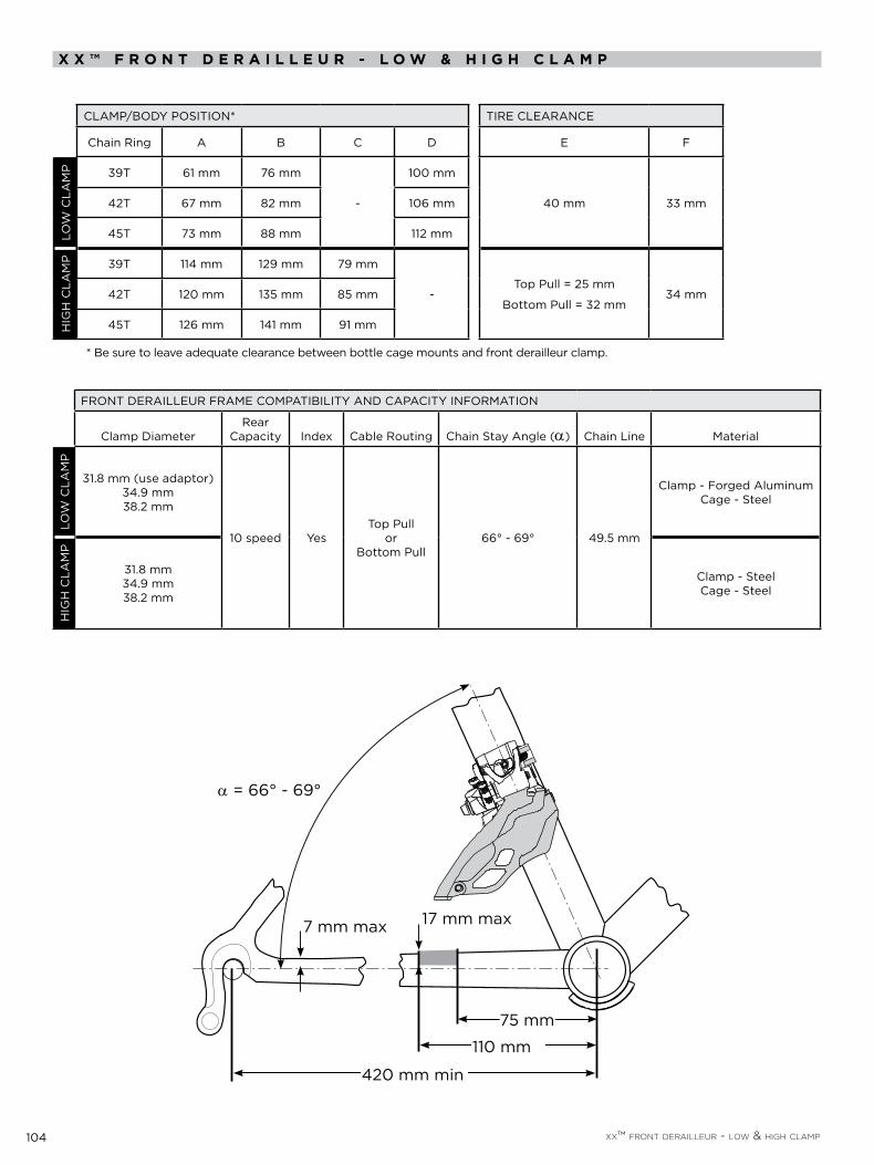
104 XX™ FRONT DERAILLEUR - LOW & HIGH CLAMP
X X ™ F R O N T D E R A I L L E U R - L O W & H I G H C L A M P
CLAMP/BODY POSITION* TIRE CLEARANCE
Chain Ring A B C D E F
LOW
CLA
MP 39T 61 mm 76 mm
-
100 mm
40 mm 33 mm42T 67 mm 82 mm 106 mm
45T 73 mm 88 mm 112 mm
HIG
H C
LAM
P 39T 114 mm 129 mm 79 mm
-Top Pull = 25 mm
Bottom Pull = 32 mm34 mm42T 120 mm 135 mm 85 mm
45T 126 mm 141 mm 91 mm
* Be sure to leave adequate clearance between bottle cage mounts and front derailleur clamp.
FRONT DERAILLEUR FRAME COMPATIBILITY AND CAPACITY INFORMATION
Clamp DiameterRear
Capacity Index Cable Routing Chain Stay Angle ( ) Chain Line Material
LOW
CLA
MP
31.8 mm (use adaptor) 34.9 mm 38.2 mm
10 speed YesTop Pull
or Bottom Pull
66° - 69° 49.5 mm
Clamp - Forged Aluminum Cage - Steel
HIG
H C
LAM
P
31.8 mm 34.9 mm 38.2 mm
Clamp - Steel Cage - Steel
= 66° - 69°
7 mm max 17 mm max
420 mm min
110 mm
75 mm
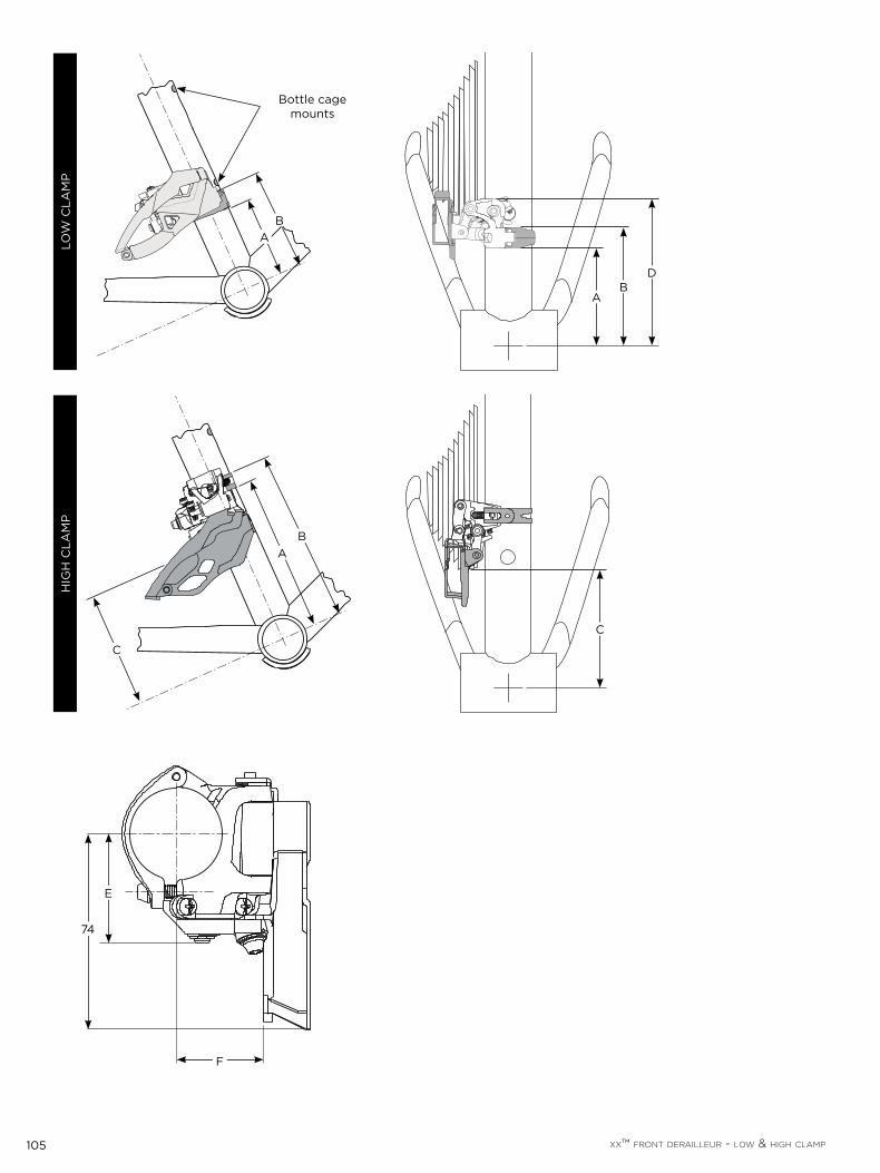
105 XX™ FRONT DERAILLEUR - LOW & HIGH CLAMP
E
F
74
BA
C
HIG
H C
LAM
PLO
W C
LAM
P
C
DB
A
Bottle cage mounts
BA

106 XX™ FRONT DERAILLEUR - DIRECT MOUNT
X X ™ F R O N T D E R A I L L E U R - D I R E C T M O U N T
MOUNTING HOLE POSITION (SWING ARM FULLY EXTENDED)
FRONT DERAILLEUR CLEARANCE
(SWING ARM FULLY COMPRESSED)
A B C
D
E
F G dmax
68 mm BB shell width
73 mm BB shell width
DIR
EC
T M
OU
NT
TYP
E
S1 45.5º±1º 48.9 mm ±0.15 mm
42.7 mm ±0.1 mm
63 mm ±0.2 mm
14.8 mm ±0.15 mm
17.3 mm ±0.15 mm -
65 mm 45 mm
37 mm
S2
66º-69º ( = )
54 mm ±0.15 mm
22.1 mm ±0.05 mm
5 mm ±0.05 mm
S3 7 mm ±0.15 mm
9.5 mm ±0.15 mm
5 mm ±0.1 mm 38.2 mm
DIR
EC
T M
OU
NT
TYP
E :
S1
DIR
EC
T M
OU
NT
TYP
E :
S2 +
S3
B
G
A
F
C
G
F
63±0.2 mm
A
B
C
22.7±0.1 mm

107 XX™ FRONT DERAILLEUR - DIRECT MOUNT
FRONT DERAILLEUR CABLE ROUTING - BOTTOM PULL (SWING ARM FULLY EXTENDED)
THREAD DIMENSION TIRE CLEARANCE
H I
K Chainring Size
L M N39T 42T 45T
DIR
EC
T M
OU
NT
8 mm 35 mm 94 mm 100 mm 106 mm 10.5º max
10.5º max M5.0x0.8-6H 40 mm 33 mm
L
K
I
Front Derailleur Cable Mounting Point
Bottom Pull
68 mm or 73 mmD
E
M
N
dmax
H
Front Derailleur Cable Mounting Point
Bottom Pull
DIR
EC
T M
OU
NT

108 XX™ FRONT DERAILLEUR - DIRECT MOUNT
FRONT DERAILLEUR FRAME COMPATIBILITY AND CAPACITY INFORMATION
Rear Capacity Index Cable Routing
Chain Stay Angle ( Chain Line Material
DIR
EC
T M
OU
NT
10 speed YesTop Pull
or Bottom Pull
66° - 69° 49.5 mm Body - Forged Aluminum Cage - Steel
7 mm max 17 mm max
420 mm min
110 mm
75 mm
= 66° - 69°
DIR
EC
T M
OU
NT
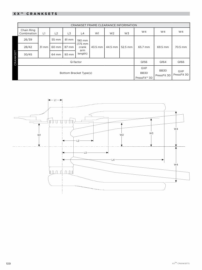
109 XX™ CRANKSETS
X X ™ C R A N K S E T S
CRANKSET FRAME CLEARANCE INFORMATION
Chain Ring Combination L1 L2 L3 L4 W1 W2 W3 W4 W4 W4
CR
AN
KSE
T
26/39
31 mm
55 mm 81 mm 190 mm (175 mm
crank arm
length)
43.5 mm 44.5 mm 52.5 mm 65.7 mm 69.5 mm 70.5 mm28/42 60 mm 87 mm
30/45 64 mm 93 mm
Q-factor Q156 Q164 Q166
Bottom Bracket Type(s)
GXP
BB30
PressFit™ 30
BB30
PressFit 30GXP
PressFit 30
W1
L2
W2W3
W4
W4
L3
L4
L1
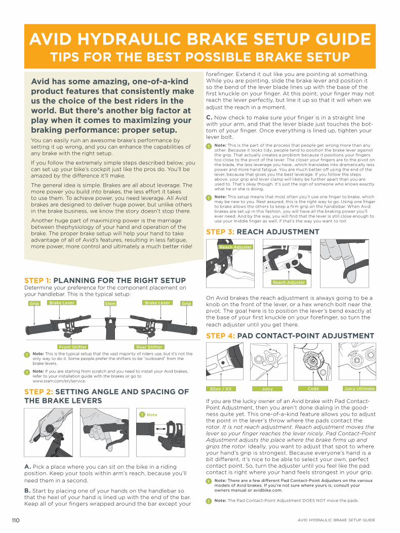
110 AVID HYDRAULIC BRAKE SETUP GUIDE
Avid has some amazing, one-of-a-kind product features that consistently make us the choice of the best riders in the world. But there’s another big factor at play when it comes to maximizing your braking performance: proper setup.You can easily ruin an awesome brake’s performance by setting it up wrong, and you can enhance the capabilities of any brake with the right setup.
If you follow the extremely simple steps described below, you can set up your bike’s cockpit just like the pros do. You’ll be amazed by the di!erence it’ll make.
The general idea is simple. Brakes are all about leverage. The more power you build into brakes, the less e!ort it takes to use them. To achieve power, you need leverage. All Avid brakes are designed to deliver huge power, but unlike others in the brake business, we know the story doesn’t stop there.
Another huge part of maximizing power is the marriage between thephysiology of your hand and operation of the brake. The proper brake setup will help your hand to take advantage of all of Avid’s features, resulting in less fatigue, more power, more control and ultimately a much better ride!
STEP 1: PLANNING FOR THE RIGHT SETUPDetermine your preference for the component placement on your handlebar. This is the typical setup:
Grip GripStemBrake Lever Brake Lever
Front Shifter Rear Shifter
! Note: This is the typical setup that the vast majority of riders use, but it’s not the only way to do it. Some people prefer the shifters to be “outboard” from the brake levers.
! Note: If you are starting from scratch and you need to install your Avid brakes, refer to your installation guide with the brakes or go to www.sram.com/en/service.
STEP 2: SETTING ANGLE AND SPACING OF THE BRAKE LEVERS
! Note
A. Pick a place where you can sit on the bike in a riding position. Keep your tools within arm’s reach, because you’ll need them in a second.
B. Start by placing one of your hands on the handlebar so that the heel of your hand is lined up with the end of the bar. Keep all of your fingers wrapped around the bar except your
forefinger. Extend it out like you are pointing at something. While you are pointing, slide the brake lever and position it so the bend of the lever blade lines up with the base of the first knuckle on your finger. At this point, your finger may not reach the lever perfectly, but line it up so that it will when we adjust the reach in a moment.
C. Now check to make sure your finger is in a straight line with your arm, and that the lever blade just touches the bot-tom of your finger. Once everything is lined up, tighten your lever bolt.
! Note: This is the part of the process that people get wrong more than any other. Because it looks tidy, people tend to position the brake lever against the grip. That actually creates a problem because it positions your fingers too close to the pivot of the lever. The closer your fingers are to the pivot on the blade, the less leverage you have...which translates into dramatically less power and more hand fatigue. You are much better o! using the end of the lever, because that gives you the best leverage. If you follow the steps above, your grip and lever clamp will likely be further apart than you are used to. That’s okay though. It’s just the sign of someone who knows exactly what he or she is doing.
! Note: This setup means that most often you’ll use one finger to brake, which may be new to you. Rest assured, this is the right way to go. Using one finger to brake allows the others to keep a firm grip on the handlebar. When Avid brakes are set up in this fashion, you will have all the braking power you’ll ever need. And by the way, you will find that the lever is still close enough to use your middle finger as well, if that’s the way you want to roll.
STEP 3: REACH ADJUSTMENT
Reach Adjuster
Reach Adjuster
On Avid brakes the reach adjustment is always going to be a knob on the front of the lever, or a hex wrench bolt near the pivot. The goal here is to position the lever’s bend exactly at the base of your first knuckle on your forefinger, so turn the reach adjuster until you get there.
STEP 4: PAD CONTACT-POINT ADJUSTMENTPA
D CONTACTIN
IN
PAD
CONTACT
I N
JuicyElixir / XX Code Juicy Ultimate
If you are the lucky owner of an Avid brake with Pad Contact-Point Adjustment, then you aren’t done dialing in the good-ness quite yet. This one-of-a-kind feature allows you to adjust the point in the lever’s throw where the pads contact the rotor. It is not reach adjustment. Reach adjustment moves the lever so your finger reaches the lever nicely. Pad Contact-Point Adjustment adjusts the place where the brake firms up and grips the rotor. Ideally, you want to adjust that spot to where your hand’s grip is strongest. Because everyone’s hand is a bit di!erent, it’s nice to be able to select your own, perfect contact point. So, turn the adjuster until you feel like the pad contact is right where your hand feels strongest in your grip.
! Note: There are a few di!erent Pad Contact-Point Adjusters on the various models of Avid brakes. If you’re not sure where yours is, consult your owners manual or avidbike.com.
! Note: The Pad Contact-Point Adjustment DOES NOT move the pads.
AVID HYDRAULIC BRAKE SETUP GUIDETIPS FOR THE BEST POSSIBLE BRAKE SETUP

111 AVID HYDRAULIC BRAKE SETUP GUIDE
STEP 5: MATCH THE OTHER SIDENow, set up the other side of the bar by matching the spacing of the clamps on the side you just completed. Visually adjust the vertical angle of the lever so it matches side one as well.! Note: Pad Contact-Point Adjustment is also used to “even out” the levers, so the
spot where each lever’s throw firms up is the same. It just feels right. And while you’re adjusting, take note – no matter what you do to the contact point, the reach never changes.
STEP 6: POSITION SHIFTERSYour brake levers are in position—now it’s time to move the shifters into place. It’s very easy. All you need to do is grip the bars like you are riding again, and extend your thumb like you are going to shift. With your thumb extended, just move the shifter until it touches it in a comfortable spot. It’s okay for this to feel like a little bit of a stretch, because you don’t shift as often as you brake, and you still have four fingers on the bar anyway.! Note: If you are using Grip Shift shifters the steps above obviously change a bit.
Since the location of the shifter is predetermined, you can skip this step.
STEP 7: RIDEYou’ve now completed a setup procedure that’s sure to enhance your braking control dramatically, so get out there and start riding. This is the way braking should be. Enjoy it!
MORE TIPS FOR THE BEST POSSIBLE BRAKE SETUPUNDERSTANDING AVID’S UNIQUE TECHNOLOGIESNot all brakes are created equal. Sure, they all go in the same spot on your bike, and they all have levers and these days most are hydraulic. But don’t be fooled. There are some major di!erences between Avid and the others out there. We have a number of unique technologies that make dialing up true performance a snap. Let’s take a moment and review some of the basics:
PAD CONTACT-POINT ADJUSTMENTWe’re proud to have been the company that invented this fea-ture before people even knew how much they needed it. As the name suggests, Pad Contact-Point Adjustment allows you to adjust the point in the lever’s throw where the pads contact the rotor. That helps you do two simple – but important – things:
It lets you pick the position you’d like your fingers to be in 1. when your brakes grip. That means you can perfectly match your fingers’ comfort with the brake’s power.
It allows you to balance both levers so the pads contact at 2. the same point. No more uneven brake levers. Pad Contact-Point Adjustment is not a reach adjuster (although all of our levers have that, too). It’s an oh-so-important performance enhancement that helps you dial in the perfect ride.
Avid Elixir
POWER RESERVE GEOMETRY™At the end of the day, a brake lever simply multiplies the force your hand generates (just like a nutcracker). Avid’s Power Re-serve Geometry represents a way of thinking about the phys-ics of leverage and your hands’ comfort. This philosophy is fundamentally di!erent than others in the business of brakes. Due to pivot placement, physics dictates that with other brake levers your fingers tend to slip o! the ends as you pull. Avid is di!erent. We designed our levers with the pivot closer to the handlebar—in fact, closer than anyone else in the industry. The resulting lever movement has less inward travel, an arc that’s closer to your fingers’ natural motion and one that delivers more force to the brake. The cool part is, every Avid lever has it.
Loosen the CPSTM bolts a little.
Squeeze the lever a few times and then hold.
Tighten the CPS bolts and ta-da! The caliper is aligned, and you are ready to ride!
1 2 3
TRI-ALIGN™ CALIPER POSITIONING SYSTEM™Another original Avid technology making your life better…There’s never been an easier brake to install. With Avid’s Tri-Align Caliper Positioning System, aligning the caliper to the rotor literally takes seconds.
Where the pad contacts the rotor
Lever at rest
“deadband”
DEADBANDDeadband is the distance your brake lever travels before the brake pad makes contact with the rotor. “Long deadband” means your lever moves a lot before the pad contacts. “Short deadband” means the lever moves very little before the pad contacts. There isn’t necessarily a right or a wrong deadband. It has a lot to do with your hand, your preference and your comfort. The quickest way to adjust the amount of deadband your brakes have is to use Avid’s proprietary Pad Contact-Point Adjustment. If your particular brake model doesn’t have Pad Contact-Point Adjustment, try the Tech Tuning Tidbits below.
TECH TUNING TIDBITSADVANCING THE PAD POSITION! Note: If the lever pulls to the bar a bleed is not necessarily
required.
Remove wheel or red plastic pad spacer insert from disc 1. brake caliper.
If your brake has Pad Contact-Point Adjustment, rotate the 2. adjuster to the full “out” position. Now it’s in the most open position (short deadband).
Squeeze the brake lever slowly several times while watching 3. the brake pads move toward each other. Stop when you see an approximate 1 mm gap between the pads.
Insert the red plastic pad spacer between the pads. The 4. pads will be a little hard to push apart, so use some force to properly spread them to the correct position. Now, remove the spacer again.
Install wheels with rotors mounted to bicycle and give the 5. lever a squeeze. The brake pads should now be properly ad-vanced to the correct position, and the brake lever will have a proper firm feel. Repeat if necessary.

112 AVID HYDRAULIC BRAKE SETUP GUIDE
ADJUSTING THE AMOUNT OF DOT FLUID IN THE BRAKEIt is possible for your brake to have too much DOT fluid in it. As a result the brakes may experience very short deadband, or in extreme cases the pistons will not retract far enough, causing the brake pads to drag on the rotor. Here’s how to take care of the problem:
If your brake has Pad Contact-Point Adjustment, rotate the adjuster to the full “out” position. Now it’s in the most open position 1. (short deadband).
Remove wheel from the bicycle.2.
Using T10 Torx™ wrench (included in the Avid Bleed Kit) remove the lever body bleed screw.3.
Carefully insert the red plastic pad spacer between the brake pads to press the pads and caliper pistons apart.4.
A small amount of DOT fluid will flow from the lever body bleed port. While still applying light pressure on the pads, insert the 5. bleed screw back into the lever body and tighten.
Spray lever body with soapy water and wipe clean with a rag.6.
Install the wheel back onto the bicycle and firmly squeeze the lever approximately 10 times to reset the pads; check for any leaks 7. around the bleed port. Now there should be more deadband and less pressure in the system. If there is still excessive pressure after completing this procedure, perform a complete bleed of the system.
Symptom First try this Then try thisShort deadband Check for DOT fluid overfill* Bleed the brake
Long deadband Advance the pads* Bleed the brake
Sticky pistons Advance the pads Lubricate with DOT fluid or Avid DOT compatible grease**
Poor pad retraction Advance the pads Check for DOT fluid overfill
Slow lever return Bleed the brake Check seals
*Of course, you should start by adjusting the Pad Contact-Point if your brake has that feature. That’s what it’s for.**Never use chain lube on the pistons. The petroleum in the oil can ruins seals and brake performance.
Our drip-free bleed process is so thorough, you’ll never wonder, “Did I get all the air out?” You can see every bit of performance-robbing air being methodically extracted from the system.
Refer to the Avid Juicy Bleed procedure at:
www.sram.com/en/service
Close our special bleed clamp and pull to reveal the trapped air you couldn’t even see before. When it’s degassed, you’re ready to bleed the brake.
1
Bleed the caliper by sucking any air out into the syringe.
Untie the lever.
3
Push the air-free fluid up through the hose, through the lever and into the other syringe attached to the lever.
4
Bleed the lever by sucking any air into the syringe. Close the bleed ports, and give yourself a high-five because you have the best-bled brakes anywhere!
6
While holding the lever push the fluid through the system until the lever returns to it’s position.
5
Tie o! lever to bar or squeeze and hold lever to bar. Tie o! is probably better because how many hands do you really have...
2
PERFORMING THE PERFECT BRAKE BLEED

GEN.0000000002866