XS Reports/Limits of · PDF fileXS Reports & Limits of Construction ... The GEOPAK Cross...
18
____________________________________ CHAPTER 16 XS Reports & Limits of Construction 16.1 XS Reports GEOPAK 2001MR Objectives Create various cross section reports: - for plan use (design elements and quantities) - as input for other programs and/or applications of GEOPAK - for construction layouts. Create and draw construction limits in the plan view file. Project Manager Reports and XS Quantities Limits of Construction Tools Menu Bar Application GEOPAK Road > Cross Sections > Cross Section Reports GEOPAK Road > Cross Sections > Construction Limits The GEOPAK Cross Section Report Utility can extract up to sixteen different reports from original and design cross-sections. For each report generated, the user must set the parameters of the existing and/or design cross sections. GEOPAK also provides an option to make custom headers for each of the reports via the User pull down menu. 16.1.1 Custom Header From the XS Report dialog box, select User > Preferences. A Report Header dialog box will appear with all options ghosted out. To activate the individual fields simply toggle on the box next to the desired field. Once you have completed the dialog box, the information will be saved as an .hdr file. This allows for the creation of a separate header for each type of report. The tolerance field determines the maximum gap allowed between cross section elements. XS Reports & Limits of Construction 16-1
Transcript of XS Reports/Limits of · PDF fileXS Reports & Limits of Construction ... The GEOPAK Cross...

____________________________________ CHAPTER 16
XS Reports & Limits of Construction 16.1 XS Reports
GEOPAK 2001MR
Objectives Create various cross section reports: - for plan use (design elements and quantities) - as input for other programs and/or applications of GEOPAK - for construction layouts. Create and draw construction limits in the plan view file.
Project Manager Reports and XS Quantities Limits of Construction
Tools
Menu Bar Application GEOPAK Road > Cross Sections > Cross Section Reports GEOPAK Road > Cross Sections > Construction Limits
The GEOPAK Cross Section Report Utility can extract up to sixteen different reports from original and design cross-sections. For each report generated, the user must set the parameters of the existing and/or design cross sections. GEOPAK also provides an option to make custom headers for each of the reports via the User pull down menu.
16.1.1 Custom Header
From the XS Report dialog box, select User > Preferences. A Report Header dialog box will appear with all options ghosted out. To activate the individual fields simply toggle on the box next to the desired field. Once you have completed the dialog box, the information will be saved as an .hdr file. This allows for the creation of a separate header for each type of report. The tolerance field determines the maximum gap allowed between cross section elements.
XS Reports & Limits of Construction 16-1

GEOPAK® __________________________________________________________
16-2 VDOT Road I Training GEOPAK 2001MR
16.1.2 Blue and Red Top Based on the dialog box settings, GEOPAK determines the offset and elevation of a slope and its breakpoints. Blue refers to the top of pavement and Red is the top of subgrade. The user must determine this by indicating text and level, color, weight and style for each surface.
16.1.3 Clearing The Clearing Report is useful for obtaining clearing and grubbing quantities. For each station, GEOPAK will list the clearing distance on each side of the chain and the width of any exception. You can obtain the results in the appropriate units. Toggle boxes for Cut Slope Rounding, Additional Clearing in Cut and Fill, and Minimum Clearing Width are provided for increased control over the output.
GEOPAK can also generate quantity sub-totals based on the value specified in Sub Every.
To use the Except Width option, you must have an existing ASCII file that includes the Beginning and Ending Station and Exception Width.
Once everything is set, you can output the information to an ASCII file
16.1.4 Closure The Closure Report provides information on the intersection point between the user defined proposed finish grade and existing ground. In addition to the ASCII report, the designer may instruct GEOPAK to close any gap either by drawing a vertical line between the endpoint of the proposed finish element and the existing ground or extending the slope of the last proposed element to intersect existing ground. The procedure will not extend existing ground. The Closure Report can be accessed within any MicroStation cross section file by selecting Closure from the main XS Reports dialog box.
16.1.5 DTM Input This process generates XYZ coordinates from cross section elements and places this information into an ASCII file for use by the DTM portion of GEOPAK. To use this dialog box simply enter the .gpk job number, chain name and station range. GEOPAK will read the cross section elements based on level, weight, color and style.

___________________________________________________________GEOPAK®
GEOPAK 2001MR XS Reports & Limits of Construction 16-3
16.1.6 DTM Proposed 3D This report is similar to DTM Input except that you can set both original and proposed cross sections at the same time. This report also differs in that it makes break lines across the cross sections.
16.1.7 HEC – 2 This process reads cross section elements and formats the information in an ASCII text file suitable for use in the HEC-2 hydraulic program.
16.1.8 HEC RAS This process reads cross section elements and formats the information in an ASCII text file suitable for use in the HEC RAS hydraulic program.
16.1.9 Multi-Line This report is useful in creating cross-sections for staged construction. Begin by entering the job number, chain name and station limits. Primary cross section element parameters must be completed before secondary element parameters. This is important due to the order in which GEOPAK reads the information. Once all the parameters have been entered, the new cross sections may be drawn to the design file or you may choose the display only option. An ASCII text file will be generated.
16.1.10 Profile Grade The Profile Grade Report is one of the most versatile reports available. It prints existing ground and design grade elevations and low point elevations for each cross section. Additionally, this report has the ability to search either for the low points or any text string that you specify and create horizontal and vertical alignments and store them directly into the .gpk. Horizontal alignments created from this report will have no curves.
16.1.11 Radial Staking The Radial Staking Report is a specialized report created for the U.S. Federal Highway Administration (FHWA).
16.1.12 RT 40 The RT 40 Report produces RDS based RT40 data. To use this dialog box simply fill in the job chain name, stationing range and the parameters of the cross section elements you wish to use.
16.1.13 Seeding Other than the usual entries, the user must enter the parameters of the elements to be seeded.
This dialog box includes slope and subtotal options as well as a way to limit the number of segments read (By-Pass Segments). The user may also establish additional seeding specifications (Additional Distance).

GEOPAK® __________________________________________________________
16-4 VDOT Road I Training GEOPAK 2001MR
Once all of the settings are complete, the report will produce seed or sod quantities written to an ASCII output file for use in plan quantities.
16.1.14 Slope Stake The Slope Stake Report is a special format report developed for the FHWA. This report generates offsets, elevations and superelevation information for each cross section. To generate this report fill in the usual cross section parameters plus Subgrade and Hub Staking information. When complete, push Apply and the report is written into an ASCII file.
16.1.15 Staking Detail The Staking Detail Report determines the tie down point between the proposed finished grade and the existing ground. GEOPAK will list the right and left offset, elevation, and slope of the finish grade and superelevation rate for each cross section. To create this report, fill in the project information and desired cross section elements’ parameters. Once complete, you have the choice between two formats, a FHWA ASCII report or a Montana DOT report (includes ditch elevations).
16.1.16 WSPRO This report takes the cross section elements and turns them into an ASCII file for use as input in the WSPRO hydraulic analysis program.
16.1.17 XS List This report creates a listing of elevations and offsets for each cross section element according to user defined parameters. You have the option of creating either an original cross section list or a design cross section list. These reports are very similar to RDS cross section lists.

___________________________________________________________GEOPAK®
16.2 Limits of Construction Project Manager Limits of Construction. Note a run must be created.
Tools
Menu Bar Application GEOPAK Road > Cross Sections > Cross Section Reports GEOPAK Road > Cross Sections > Construction Limits
When the Limits of Construction dialog box in invoked, the Limits of Construction dialog box opens.
The user must specify the Job number, the chain name, and the file containing the plan view information. The Existing Ground and the Proposed Finish Grade sections should be filled by the run if Project Manager is utilized.
The Parameters button opens the dialog box below. The symbology for the cut, fill, and transition construction limits can be set in this dialog box.
The Place Construction Limit toggle allows the user to place various text strings along the construction limits. Selecting the Parameters button, and making the desired changes in the dialog box shown on the next page will set the symbology for these text strings.
GEOPAK 2001MR XS Reports & Limits of Construction 16-5

GEOPAK® __________________________________________________________
The Radius of Display field is the size of the display circle when GEOPAK is scanning the cross-sections.
The last option in the main Limits of Construction dialog box is the Tie Down Option. There are two Tie Down Options. If the All Tie Down option is set, all tie downs within a section are plotted. (I.e. wide medians, outer roadways, ramps, etc. may have tie downs in between the limits of the main roadway, and the outer roadway or ramp.) If the Outer Tie Down option is selected, then only the outmost tie downs are plotted.
Once the Apply button is clicked, the limits of construction and the optional text are drawn into the plan view file at the specified symbology.
16-6 VDOT Road I Training GEOPAK 2001MR

___________________________________________________________GEOPAK®
LAB 16: Cross Section Reports,Driveway Profiles, and Limits of Construction
16.1 Cross Section Reports Step 1. Execute C:\data\geo\VDOT\road1\LAB16.EXE.
Step 2. Open c:\data\geo\vdot\road1\d17682xsmainline.dgn.
Step 3. Access Project Manager.
Step 4. Select Reports and XS Quantities.
Step 5. From the XS Reports dialog box, select the User > Preferences dialog box.
Set the tolerance to .01.
Dismiss the Report Header dialog box.
Step 6. From the XS Reports dialog box, select the Profile Grade report.
We are going to use this report to create a Chain and Profile along our left edge of shoulder. We’ll use this information later to help in the creation of our driveway profiles.
GEOPAK 2001MR LAB 16: Cross Section Reports,Driveway Profiles, and Limits of Construction 16-7

GEOPAK® __________________________________________________________
Step 7. Fill out the Profile Grade dialog box as shown and click Apply. To add the Text Search information to the collection box, push the ADD button. (Store Text: EOSLOUT)
Step 8. After processing is complete, dismiss the dialog box.
Step 9. Access COGO.
Step 10. Access COGO Navigator using the icon
or use the Tools > Navigator pulldown.
16-8 VDOT Road I Training GEOPAK 2001MR

___________________________________________________________GEOPAK®
Step 11. Use the Chain option to see a list of the stored chains. Notice EOSL has been stored.
Step 12. Use the Profile option to see a list of the stored profiles. Notice EOSL has been stored
Step 13. Exit COGO.
Step 14. From the XS Reports dialog box, select the DTM Input report.
We’ll use this report to create a proposed model (dtm) from our cross sections. We’ll also use this information later in the creation of our driveway profiles.
Step 15. Fill out the DTM Input dialog box as shown and click Apply.
Note: The levels for XS Elements should only refer to 2-4. These are the levels that make up the top of Finish Grade.
Note that in Step 15 we only created a .dat file. This is an ascii file that is used to create the DTM. We’ll create the dtm in the next section.
Step 16. After processing is complete, dismiss the DTM Input dialog box.
GEOPAK 2001MR LAB 16: Cross Section Reports,Driveway Profiles, and Limits of Construction 16-9
GEOPAK® __________________________________________________________
Step 17. Also dismiss the XS Reports dialog box.
16.2 Driveway Profiles Step 1. Before beginning the process to create the driveway profiles, we’ll need to create the
proposed DTM.
Select the Existing Ground button from the Road Project: 17682.prj workflow dialog box.
Step 2. Select the previously created run ‘ground1’ and press OK.
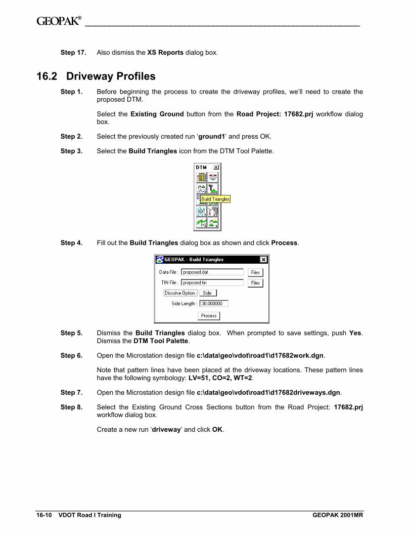
Step 3. Select the Build Triangles icon from the DTM Tool Palette.
Step 4. Fill out the Build Triangles dialog box as shown and click Process.
Step 5. Dismiss the Build Triangles dialog box. When prompted to save settings, push Yes. Dismiss the DTM Tool Palette.
Step 6. Open the Microstation design file c:\data\geo\vdot\road1\d17682work.dgn.
Note that pattern lines have been placed at the driveway locations. These pattern lines have the following symbology: LV=51, CO=2, WT=2.
Step 7. Open the Microstation design file c:\data\geo\vdot\road1\d17682driveways.dgn.
Step 8. Select the Existing Ground Cross Sections button from the Road Project: 17682.prj workflow dialog box.
Create a new run ‘driveway’ and click OK.
16-10 VDOT Road I Training GEOPAK 2001MR

___________________________________________________________GEOPAK®
Step 9. Fill out the dialog boxes as shown and click Draw.
Proposed Surface Symbology (lv = 1, co=4, wt=3, lc=0)
Existing Surface Symbology (lv=1, co=1, wt=5, lc=2)
Step 10. Dismiss the Draw Cross Sections dialog box and Save Settings.
Review the ground lines drawn. Notice that the proposed ground line may not terminate precisely on the existing ground. This is because elevations are being interpolated between proposed cross sections.
You can tie this down manually or you can use the XS Reports > Closure Report.
Step 11. Select the Proposed Cross Sections button from the Road Project: 17682.prj workflow dialog box.
Create a new run ‘driveway’ and click OK.
GEOPAK 2001MR LAB 16: Cross Section Reports,Driveway Profiles, and Limits of Construction 16-11

GEOPAK® __________________________________________________________
Step 12. Fill out the XS DGN File category as shown:
Step 13. Fill out the Pattern category as shown:
Step 14. Fill out the Existing Ground category as shown:
16-12 VDOT Road I Training GEOPAK 2001MR

___________________________________________________________GEOPAK®
Step 15. Fill out the Shapes category as shown:
Step 16. Under the Shape Clusters category, add the Mainline chain and profile to the list box as was done in previous exercises.
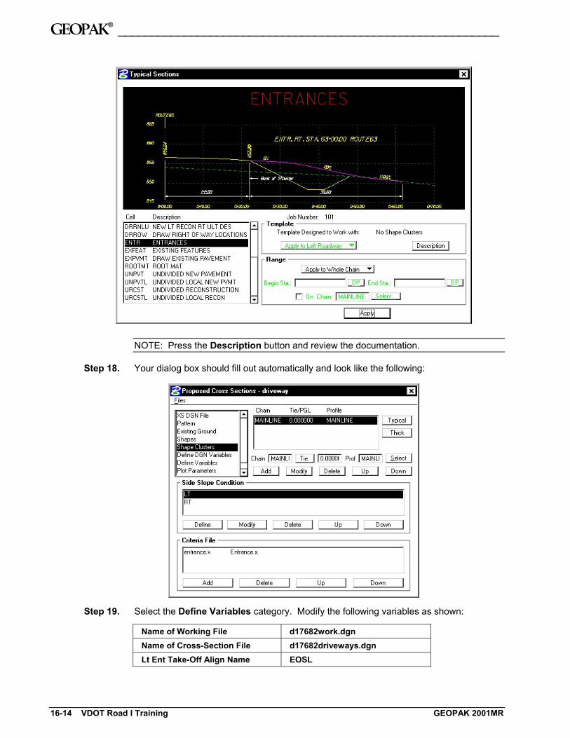
Step 17. Press the Typical button to access the Typical Section Generator.
Select the Typical ENTR and press Apply.
GEOPAK 2001MR LAB 16: Cross Section Reports,Driveway Profiles, and Limits of Construction 16-13
GEOPAK® __________________________________________________________
NOTE: Press the Description button and review the documentation.
Step 18. Your dialog box should fill out automatically and look like the following:
Step 19. Select the Define Variables category. Modify the following variables as shown:
Name of Working File d17682work.dgn Name of Cross-Section File d17682driveways.dgn Lt Ent Take-Off Align Name EOSL
16-14 VDOT Road I Training GEOPAK 2001MR
___________________________________________________________GEOPAK®
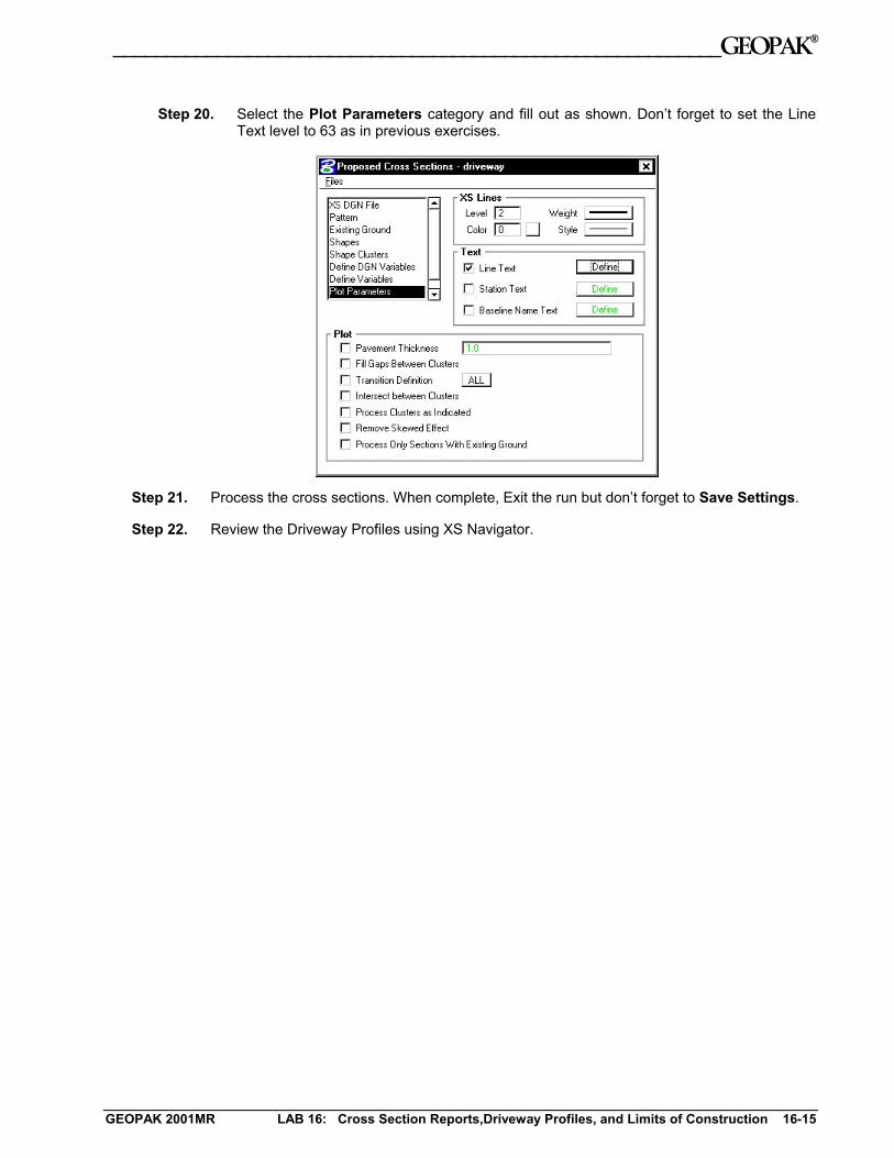
Step 20. Select the Plot Parameters category and fill out as shown. Don’t forget to set the Line Text level to 63 as in previous exercises.
Step 21. Process the cross sections. When complete, Exit the run but don’t forget to Save Settings.
Step 22. Review the Driveway Profiles using XS Navigator.
GEOPAK 2001MR LAB 16: Cross Section Reports,Driveway Profiles, and Limits of Construction 16-15

GEOPAK® __________________________________________________________
16.3 Plan View Limits of Construction Step 1. Open the Microstation design file c:\data\geo\vdot\road1\d17682xsmainline.dgn.
Step 2. From the Road workflow dialog box, select Limits of Construction. Create a run called Mainline.
Step 3. Populate the Limits of Construction dialog box as shown:
Step 4. Click the Parameters button to open the Plot Parameters dialog box. Populate as shown:
16-16 VDOT Road I Training GEOPAK 2001MR

___________________________________________________________GEOPAK®
Note: Cut Line Style = 5;Fill Line Style = 3;Transition Line Style = 4
Step 5. Click OK to close the Plot Parameters dialog box.
Step 6. Click Apply to process the Limits of Construction.
Step 7. Exit the Limits of Construction dialog box and Save Settings. Review the limits of construction in c:\data\geo\vdot\road1\d17682des.dgn.
Since GEOPAK does not create the Limits of Construction exactly like VDOT would like to see them, we will use a special application to update them to the correct symbology.
Step 8. From the Road workflow dialog box, select Plan View Design.
Step 9. From the Plan View Design tool palette, select D&C Manager.
Step 10. Navigate to the category Road Design > Special Applications.
Step 11. Important! Make sure that all of your Limits of Construction are shown in View 1.
Step 12. Within this category, double-click on the item Update LOC.
Step 13. At the following prompt, click OK.
GEOPAK 2001MR LAB 16: Cross Section Reports,Driveway Profiles, and Limits of Construction 16-17
GEOPAK® __________________________________________________________
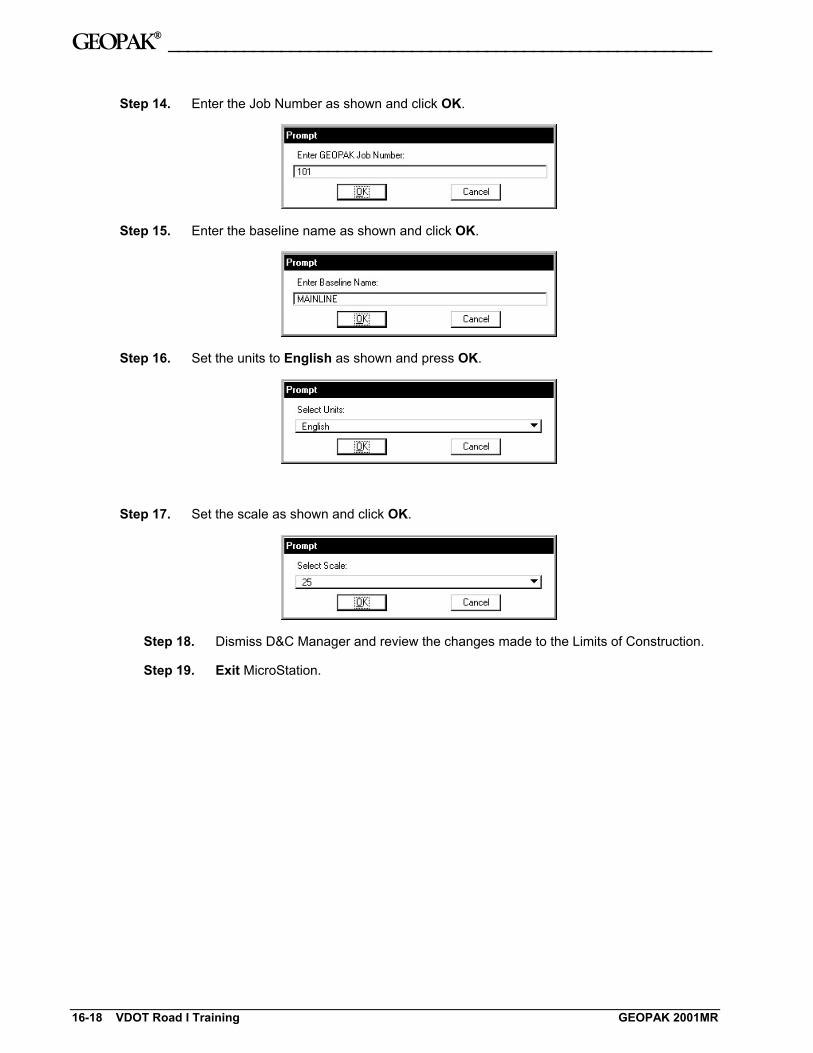
Step 14. Enter the Job Number as shown and click OK.
Step 15. Enter the baseline name as shown and click OK.
Step 16. Set the units to English as shown and press OK.
Step 17. Set the scale as shown and click OK.
Step 18. Dismiss D&C Manager and review the changes made to the Limits of Construction.
Step 19. Exit MicroStation.
16-18 VDOT Road I Training GEOPAK 2001MR