XPS 8930 Service Manual - Delltopics-cdn.dell.com/pdf/xps-8930-desktop_service-manual...XPS 8930...
142
XPS 8930 Service Manual Computer Model: XPS 8930 Regulatory Model: D24M Regulatory Type: D24M001
Transcript of XPS 8930 Service Manual - Delltopics-cdn.dell.com/pdf/xps-8930-desktop_service-manual...XPS 8930...

XPS 8930
Service Manual
Computer Model: XPS 8930Regulatory Model: D24MRegulatory Type: D24M001

Notes, cautions, and warningsNOTE: A NOTE indicates important information that helps you make better use of your product.
CAUTION: A CAUTION indicates either potential damage to hardware or loss of data and tells you how to avoid the problem.
WARNING: A WARNING indicates a potential for property damage, personal injury, or death.
Copyright © 2017 Dell Inc. or its subsidiaries. All rights reserved. Dell, EMC, and other trademarks are trademarks of Dell Inc. or its subsidiaries. Other trademarks may be trademarks of their respective owners.
2017 - 10
Rev. A00

Contents
Before working inside your computer............................ 11Before you begin ......................................................................................11Safety instructions....................................................................................11Recommended tools................................................................................ 12
Screw list................................................................................................. 13
After working inside your computer..............................15
Technical overview....................................................... 16Inside view of your computer................................................................... 17System-board components...................................................................... 18
Removing the right-side cover.....................................20Procedure............................................................................................... 20
Replacing the right-side cover..................................... 22Procedure................................................................................................23
Removing the front bezel ............................................ 24Prerequisites............................................................................................24Procedure............................................................................................... 25
Replacing the front bezel............................................. 27Procedure................................................................................................27Post-requisites.........................................................................................27
3

Removing the optical drive...........................................28Prerequisites ...........................................................................................28Procedure................................................................................................28
Replacing the optical drive...........................................34Procedure................................................................................................34
Post-requisites.................................................................................. 34Post-requisites........................................................................................ 34
Removing the top cover...............................................35Prerequisites........................................................................................... 35Procedure............................................................................................... 35
Replacing the top cover............................................... 37Procedure................................................................................................37Post-requisites.........................................................................................37
Removing the bottom cover.........................................38Prerequisites............................................................................................38Procedure............................................................................................... 38
Replacing the bottom cover..........................................41Procedure................................................................................................ 41Post-requisites......................................................................................... 41
Removing the primary hard-drive.................................42Prerequisites............................................................................................42Procedure ...............................................................................................42
Replacing the primary hard-drive ................................45Procedure .............................................................................................. 45Post-requisites........................................................................................ 45
4

Removing the secondary hard-drive............................ 46Prerequisites........................................................................................... 46Procedure............................................................................................... 46
Replacing the secondary hard-drive.............................50Post-requisites........................................................................................ 50Procedure............................................................................................... 50
Removing the solid-state drive..................................... 51Prerequisites............................................................................................ 51Procedure................................................................................................ 51
Replacing the solid-state drive.....................................53Procedure............................................................................................... 53Post-requisites........................................................................................ 54
Removing the power-supply unit................................. 56Prerequisites........................................................................................... 56Procedure............................................................................................... 56
Replacing the power-supply unit..................................60Procedure............................................................................................... 60Post-requisites.........................................................................................61
Removing the coin-cell battery.................................... 62Prerequisites........................................................................................... 62Procedure............................................................................................... 62
Replacing the coin-cell battery.................................... 64Procedure............................................................................................... 64Post-requisites........................................................................................ 64
5

Removing the graphics card.........................................65Prerequisites........................................................................................... 65Procedure............................................................................................... 65
Replacing the graphics card......................................... 67Procedure................................................................................................67Post-requisites........................................................................................ 67
Removing the full-length graphics cards......................68Prerequisites........................................................................................... 68Procedure............................................................................................... 69
Replacing the full-length graphics cards.......................71Procedure................................................................................................ 71Post-requisites......................................................................................... 71
Removing the memory modules................................... 72Prerequisites............................................................................................72Procedure................................................................................................72
Replacing the memory modules....................................74Procedure................................................................................................74Post-requisites........................................................................................ 76
Removing the power-button module............................ 77Prerequisites............................................................................................77Procedure................................................................................................77
Replacing the power-button module............................ 79Procedure................................................................................................79Post-requisites........................................................................................ 79
6

Removing the top I/O-panel........................................ 80Prerequisites........................................................................................... 80Procedure............................................................................................... 80
Replacing the top I/O-panel.........................................83Procedure............................................................................................... 83Post-requisites........................................................................................ 83
Removing blower and heat-sink assembly....................84Prerequisites............................................................................................84Procedure............................................................................................... 84
Replacing blower and heat-sink assembly.................... 88Procedure............................................................................................... 88Post-requisites........................................................................................ 88
Removing the VR heat sink..........................................90Prerequisites........................................................................................... 90Procedure............................................................................................... 90
Replacing the VR heat sink.......................................... 92Procedure............................................................................................... 92Post-requisites........................................................................................ 92
Removing the processor fan and heat-sink assembly... 93Prerequisites............................................................................................93Procedure............................................................................................... 93
Replacing the processor fan and heat-sink assembly... 95Procedure............................................................................................... 95Post-requisites........................................................................................ 95
7

Removing the chassis fan............................................ 96Prerequisites........................................................................................... 96Procedure............................................................................................... 96
Replacing the chassis fan.............................................99Procedure............................................................................................... 99Post-requisites........................................................................................ 99
Removing the processor............................................. 101Prerequisites...........................................................................................101Procedure...............................................................................................101
Replacing the processor............................................. 103Procedure.............................................................................................. 103Post-requisites.......................................................................................105
Removing the wireless card........................................ 106Prerequisites.......................................................................................... 106Procedure..............................................................................................106
Replacing the wireless card........................................ 108Procedure.............................................................................................. 108Post-requisites.......................................................................................109
Removing the antenna................................................ 110Prerequisites...........................................................................................110Procedure...............................................................................................110
Replacing the antenna.................................................113Procedure...............................................................................................113Post-requisites........................................................................................113
8
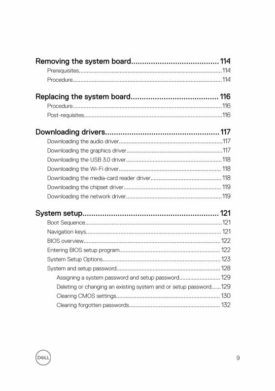
Removing the system board........................................ 114Prerequisites...........................................................................................114Procedure...............................................................................................114
Replacing the system board........................................ 116Procedure...............................................................................................116Post-requisites........................................................................................116
Downloading drivers.................................................... 117Downloading the audio driver..................................................................117Downloading the graphics driver.............................................................117Downloading the USB 3.0 driver............................................................. 118Downloading the Wi-Fi driver................................................................. 118Downloading the media-card reader driver............................................. 118Downloading the chipset driver.............................................................. 119Downloading the network driver.............................................................119
System setup.............................................................. 121Boot Sequence.......................................................................................121Navigation keys...................................................................................... 121BIOS overview....................................................................................... 122Entering BIOS setup program................................................................ 122System Setup Options........................................................................... 123System and setup password.................................................................. 128
Assigning a system password and setup password.......................... 129Deleting or changing an existing system and or setup password......129Clearing CMOS settings.................................................................. 130Clearing forgotten passwords.......................................................... 132
9

Troubleshooting.......................................................... 136Flashing the BIOS.................................................................................. 136Flashing BIOS (USB key)....................................................................... 136Power-supply unit Built-in Self Test (BIST)............................................ 137
Steps to confirm that power-supply unit is defective.......................138Enhanced Pre-Boot System Assessment (ePSA) diagnostics................ 138
Running the ePSA diagnostics......................................................... 139Diagnostics............................................................................................ 139Wi-Fi power cycle.................................................................................. 140
Getting help and contacting Dell................................. 141Self-help resources................................................................................. 141Contacting Dell...................................................................................... 142
10

Before working inside your computer
NOTE: The images in this document may differ from your computer depending on the configuration you ordered.
Before you begin
1 Save and close all open files and exit all open applications.
2 Shut down your computer. Click Start → Power → Shut down.
NOTE: If you are using a different operating system, see the documentation of your operating system for shut-down instructions.
3 Disconnect your computer and all attached devices from their electrical outlets.
4 Disconnect all attached network devices and peripherals, such as keyboard, mouse, and monitor from your computer.
5 Remove any media card and optical disc from your computer, if applicable.
6 After the computer is unplugged, press and hold the power button for 5 seconds to ground the system board.
Safety instructions
Use the following safety guidelines to protect your computer from potential damage and ensure your personal safety.
WARNING: Before working inside your computer, read the safety information that shipped with your computer. For more safety best practices, see the Regulatory Compliance home page at www.dell.com/regulatory_compliance.
WARNING: Disconnect all power sources before opening the computer cover or panels. After you finish working inside the computer, replace all covers, panels, and screws before connecting to the electrical outlet.
11
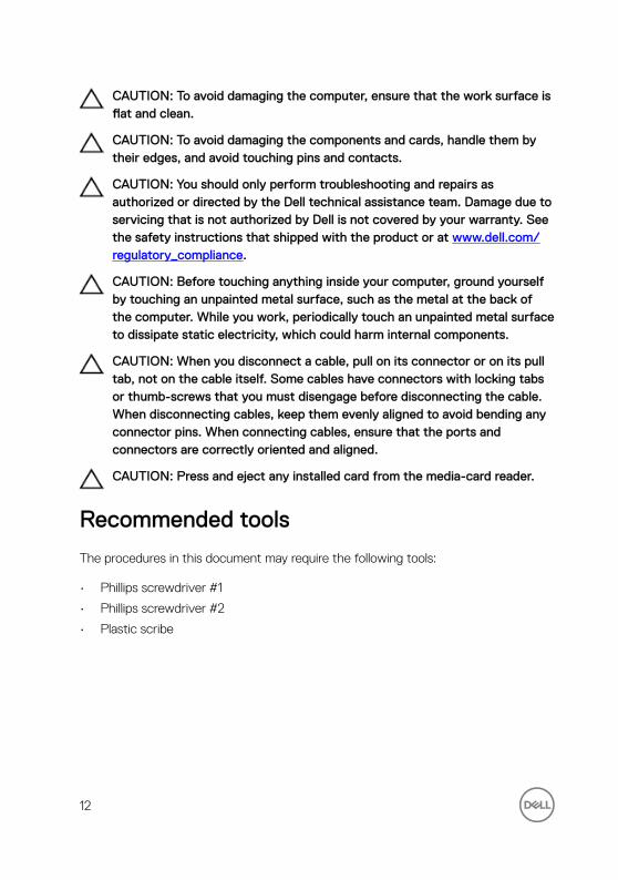
CAUTION: To avoid damaging the computer, ensure that the work surface is flat and clean.
CAUTION: To avoid damaging the components and cards, handle them by their edges, and avoid touching pins and contacts.
CAUTION: You should only perform troubleshooting and repairs as authorized or directed by the Dell technical assistance team. Damage due to servicing that is not authorized by Dell is not covered by your warranty. See the safety instructions that shipped with the product or at www.dell.com/regulatory_compliance.
CAUTION: Before touching anything inside your computer, ground yourself by touching an unpainted metal surface, such as the metal at the back of the computer. While you work, periodically touch an unpainted metal surface to dissipate static electricity, which could harm internal components.
CAUTION: When you disconnect a cable, pull on its connector or on its pull tab, not on the cable itself. Some cables have connectors with locking tabs or thumb-screws that you must disengage before disconnecting the cable. When disconnecting cables, keep them evenly aligned to avoid bending any connector pins. When connecting cables, ensure that the ports and connectors are correctly oriented and aligned.
CAUTION: Press and eject any installed card from the media-card reader.
Recommended tools
The procedures in this document may require the following tools:
• Phillips screwdriver #1
• Phillips screwdriver #2
• Plastic scribe
12

Screw list
The following table provides the list of screws that are used for securing different components to the computer.Table 1. Screw list
Component Secured to Screw type Quantity Screw image
Hard drive Hard-drive bracket
#6-32x1/4'' 4
Hard-drive cage
Chassis #6-32x1/4'' 6 (two per hard-drive cage installed)
Power-supply bracket
Chassis #6-32x1/4'' 2
Power-supply unit
Chassis #6-32x1/4'' 4
Blower Heat-sink assembly
#6-32x1/4'' 3
Chassis fan Chassis #6-32x1/4'' 1
Power button module
Top panel #6-32x1/4'' 1
Solid-state drive
System board M2x2.5 1
Wireless card System board M2x2.5 1
Top IO panel Chassis #6-32x1/4'' 4
13

Component Secured to Screw type Quantity Screw image
Optical drive Optical-drive bracket
M2x2.5 1
System board Chassis #6-32x1/4'' 8
14
After working inside your computer
CAUTION: Leaving stray or loose screws inside your computer may severely damage your computer.
1 Replace all screws and ensure that no stray screws remain inside your computer.
2 Connect any external devices, peripherals, or cables you removed before working on your computer.
3 Replace any media cards, discs, or any other parts that you removed before working on your computer.
4 Connect your computer and all attached devices to their electrical outlets.
5 Turn on your computer.
15

Technical overviewWARNING: Before working inside your computer, read the safety information that shipped with your computer and follow the steps in Before working inside your computer. After working inside your computer, follow the instructions in After working inside your computer. For more safety best practices, see the Regulatory Compliance home page at www.dell.com/regulatory_compliance.
16
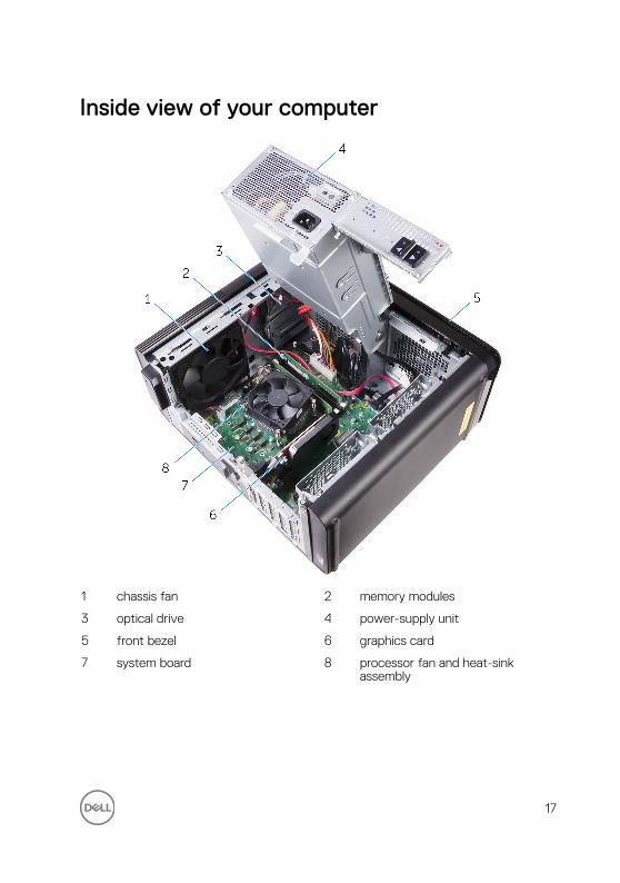
Inside view of your computer
1 chassis fan 2 memory modules
3 optical drive 4 power-supply unit
5 front bezel 6 graphics card
7 system board 8 processor fan and heat-sink assembly
17
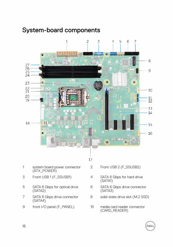
System-board components
1 system board power connector (ATX_POWER)
2 Front USB 2 (F_SSUSB2)
3 Front USB 1 (F_SSUSB1) 4 SATA 6 Gbps for hard drive (SATA1)
5 SATA 6 Gbps for optical drive (SATA2)
6 SATA 6 Gbps drive connector (SATA3)
7 SATA 6 Gbps drive connector (SATA4)
8 solid-state drive slot (M.2 SSD)
9 front I/O panel (F_PANEL) 10 media card reader connector (CARD_READER)
18

11 CMOS-reset jumper (CMOS JUMPER)
12 password-reset jumper (PASSWORD JUMPER)
13 PCI-Express x16 card slot (SLOT1) 14 PCI-Express x1 card slots (SLOT 2 and SLOT 3)
15 PCI-Express x4 card slot (SLOT 4) 16 front audio connector (F_audio)
17 wireless-card slot (M.2_SLOT1) 18 CPU power cable (ATX_CPU)
19 chassis-fan connector (TOP_FAN) 20 processor socket
21 processor release latch 22 processor-fan connector (CPU_FAN)
23 coin-cell battery (CMOS BATTERY) 24 memory-module slot (DIMM3)
25 memory-module slot (DIMM1) 26 memory-module slot (DIMM4)
27 memory-module slot (DIMM2)
19

Removing the right-side coverWARNING: Before working inside your computer, read the safety information that shipped with your computer and follow the steps in Before working inside your computer. After working inside your computer, follow the instructions in After working inside your computer. For more safety best practices, see the Regulatory Compliance home page at www.dell.com/regulatory_compliance.
Procedure
1 Place the computer in an upright position.
2 Pull the right-side cover release latch.
3 Lift the right-side cover and then slide it towards the top of the computer.
20
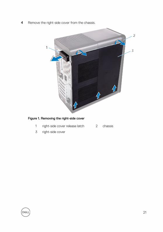
4 Remove the right-side cover from the chassis.
Figure 1. Removing the right-side cover
1 right-side cover release latch 2 chassis
3 right-side cover
21

Replacing the right-side coverWARNING: Before working inside your computer, read the safety information that shipped with your computer and follow the steps in Before working inside your computer. After working inside your computer, follow the instructions in After working inside your computer. For more safety best practices, see the Regulatory Compliance home page at www.dell.com/regulatory_compliance.
22
Procedure
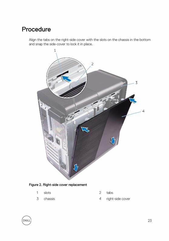
Align the tabs on the right-side cover with the slots on the chassis in the bottom and snap the side-cover to lock it in place.
Figure 2. Right-side cover replacement
1 slots 2 tabs
3 chassis 4 right-side cover
23
Removing the front bezel WARNING: Before working inside your computer, read the safety information that shipped with your computer and follow the steps in Before working inside your computer. After working inside your computer, follow the instructions in After working inside your computer. For more safety best practices, see the Regulatory Compliance home page at www.dell.com/regulatory_compliance.
Prerequisites
1 Remove the right-side cover.
2 Remove the optical drive.
24

Procedure
1 Release the front-bezel tabs sequentially from the top, one at a time by moving them away from the slots on the front chassis.
Figure 3. Removing the front bezel
1 front bezel 2 front-bezel tabs
25

2 Rotate and pull the front bezel away from the front of the chassis to release the front-bezel from the slots on the chassis.
Figure 4. Removing the front bezel
1 slots 2 front bezel
3 front chassis
26
Replacing the front bezelWARNING: Before working inside your computer, read the safety information that shipped with your computer and follow the steps in Before working inside your computer. After working inside your computer, follow the instructions in After working inside your computer. For more safety best practices, see the Regulatory Compliance home page at www.dell.com/regulatory_compliance.
Procedure
1 Align the tabs on the front bezel with the slots on the chassis.
2 Rotate the front bezel towards the chassis until the front bezel tabs snap into place.
Post-requisites
1 Replace the optical drive.
2 Replace the right-side cover.
27

Removing the optical driveWARNING: Before working inside your computer, read the safety information that shipped with your computer and follow the steps in Before working inside your computer. After working inside your computer, follow the instructions in After working inside your computer. For more safety best practices, see the Regulatory Compliance home page at www.dell.com/regulatory_compliance.
Prerequisites
1 Remove the right-side cover.
2 Follow the procedure from step 1 to step 2 in “Removing the power-supply unit”.
Procedure
1 Disconnect the power and data cables from the optical drive.
2 Pull the release tab on the optical-drive cage towards the bottom of the computer.
28

3 Push to slide out the optical drive through the front of the computer.
Figure 5. Removing the optical drive
1 power cable 2 data cable
3 optical drive 4 optical-drive cage
5 release tab
29

4 Push and slide the optical drive through the front of the computer.
Figure 6. Removing the optical drive
1 optical-drive bezel 2 optical drive
3 front bezel
30

5 Remove the screw that secures the optical-drive bracket to the optical drive.
Figure 7. Removing the optical drive
1 M2x2.5 screw 2 optical-drive bracket
3 optical drive
31

6 Eject the optical drive by inserting a pointed screwdriver in the optical-drive eject hole.
Figure 8. Removing the optical-drive bezel
1 optical drive 2 optical-drive eject hole
3 optical-drive bezel
32

7 Using a plastic scribe, gently push the optical-drive bezel away to remove the tabs from the slots on the optical drive.
Figure 9. Removing the optical-drive bezel
1 optical-drive bezel 2 slot
3 tab 4 plastic scribe
33
Replacing the optical driveWARNING: Before working inside your computer, read the safety information that shipped with your computer and follow the steps in Before working inside your computer. After working inside your computer, follow the instructions in After working inside your computer. For more safety best practices, see the Regulatory Compliance home page at www.dell.com/regulatory_compliance.
Procedure
1 Align the screw hole on the optical-drive bracket with the screw hole on the optical drive.
2 Replace the screw that secures the optical-drive bracket to the optical drive.
3 Align the tabs on the optical-drive bezel with slots on the optical drive and snap it in place.
4 Slide the optical drive into the optical-drive cage through the front of the computer till it snaps into place.
5 Connect the power and data cables to the optical drive.
Post-requisites
1 Follow the procedure from step 9 to step 10 in “Replacing the power-supply unit”.
2 Replace the right-side cover.
Post-requisites
1 Follow the procedure from step 9 to step 10 in “Replacing the power-supply unit”.
2 Replace the right-side cover.
34
Removing the top coverWARNING: Before working inside your computer, read the safety information that shipped with your computer and follow the steps in Before working inside your computer. After working inside your computer, follow the instructions in After working inside your computer. For more safety best practices, see the Regulatory Compliance home page at www.dell.com/regulatory_compliance.
Prerequisites
1 Remove the right-side cover.
2 Remove the front bezel.
3 Remove the optical drive.
Procedure
1 Place the computer in an upright position.
35
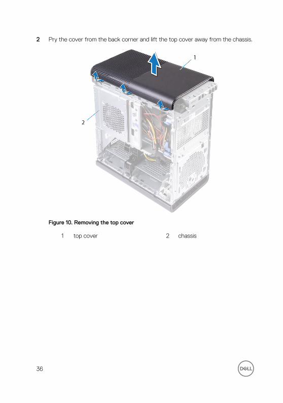
2 Pry the cover from the back corner and lift the top cover away from the chassis.
Figure 10. Removing the top cover
1 top cover 2 chassis
36

Replacing the top coverWARNING: Before working inside your computer, read the safety information that shipped with your computer and follow the steps in Before working inside your computer. After working inside your computer, follow the instructions in After working inside your computer. For more safety best practices, see the Regulatory Compliance home page at www.dell.com/regulatory_compliance.
Procedure
Align the tabs on the top cover with the slots on the top panel and press the top cover until it snaps into place.
Post-requisites
1 Replace the optical drive.
2 Replace the front bezel.
3 Replace the right-side cover.
37

Removing the bottom coverWARNING: Before working inside your computer, read the safety information that shipped with your computer and follow the steps in Before working inside your computer. After working inside your computer, follow the instructions in After working inside your computer. For more safety best practices, see the Regulatory Compliance home page at www.dell.com/regulatory_compliance.
Prerequisites
1 Remove the right-side cover.
2 Remove the front bezel.
3 Remove the optical drive.
Procedure
1 Lay the computer on the left side.
38
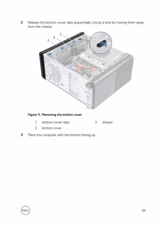
2 Release the bottom-cover tabs sequentially, one at a time by moving them away from the chassis.
Figure 11. Removing the bottom cover
1 bottom-cover tabs 2 chassis
3 bottom cover
3 Place the computer with the bottom facing up.
39

4 Pry and lift the bottom cover away from the chassis.
Figure 12. Removing the bottom cover
1 bottom cover 2 chassis
40
Replacing the bottom coverWARNING: Before working inside your computer, read the safety information that shipped with your computer and follow the steps in Before working inside your computer. After working inside your computer, follow the instructions in After working inside your computer. For more safety best practices, see the Regulatory Compliance home page at www.dell.com/regulatory_compliance.
Procedure
Align the tabs on the bottom cover with the slots on the bottom panel and press the bottom cover until it snaps in place.
Post-requisites
1 Replace the optical drive.
2 Replace the front bezel.
3 Replace the right-side cover.
41

Removing the primary hard-driveWARNING: Before working inside your computer, read the safety information that shipped with your computer and follow the steps in Before working inside your computer. After working inside your computer, follow the instructions in After working inside your computer. For more safety best practices, see the Regulatory Compliance home page at www.dell.com/regulatory_compliance.
CAUTION: Hard drives are fragile. Exercise care when handling the hard drive.
CAUTION: To avoid data loss, do not remove the hard drive while the computer is in sleep or on state.
Prerequisites
Remove the right-side cover.
Procedure
1 Disconnect the data and power cables from the hard-drive.
42
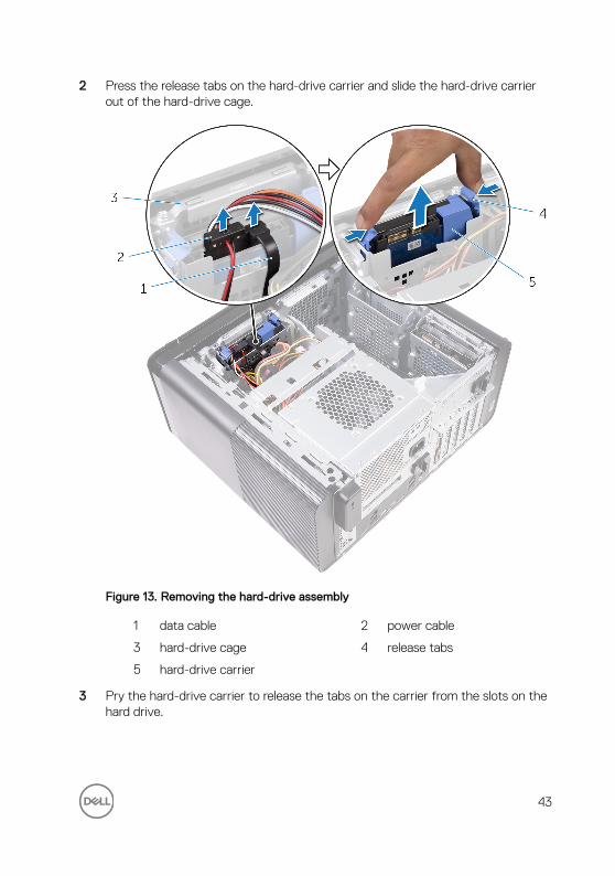
2 Press the release tabs on the hard-drive carrier and slide the hard-drive carrier out of the hard-drive cage.
Figure 13. Removing the hard-drive assembly
1 data cable 2 power cable
3 hard-drive cage 4 release tabs
5 hard-drive carrier
3 Pry the hard-drive carrier to release the tabs on the carrier from the slots on the hard drive.
43
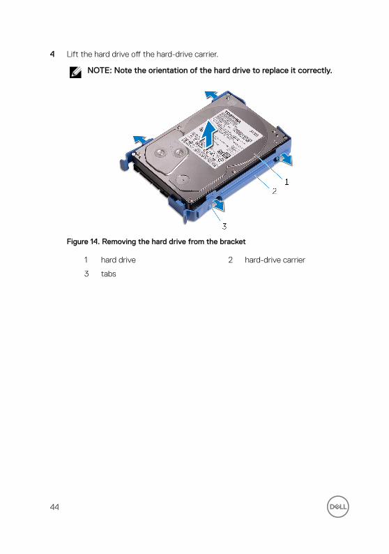
4 Lift the hard drive off the hard-drive carrier.
NOTE: Note the orientation of the hard drive to replace it correctly.
Figure 14. Removing the hard drive from the bracket
1 hard drive 2 hard-drive carrier
3 tabs
44

Replacing the primary hard-drive WARNING: Before working inside your computer, read the safety information that shipped with your computer and follow the steps in Before working inside your computer. After working inside your computer, follow the instructions in After working inside your computer. For more safety best practices, see the Regulatory Compliance home page at www.dell.com/regulatory_compliance.
CAUTION: Hard drives are fragile. Exercise care when handling the hard drive.
Procedure
1 Place the hard drive into the hard-drive carrier and align the tabs on the bracket with the slots on the hard drive.
2 Snap the hard-drive carrier into the hard drive.
3 Slide the hard-drive carrier into the hard-drive cage until it snaps into place.
4 Connect the data and power cables to the hard-drive.
Post-requisites
Replace the right-side cover.
45

Removing the secondary hard-drive
WARNING: Before working inside your computer, read the safety information that shipped with your computer and follow the steps in Before working inside your computer. After working inside your computer, follow the instructions in After working inside your computer. For more safety best practices, see the Regulatory Compliance home page at www.dell.com/regulatory_compliance.
CAUTION: Hard drives are fragile. Exercise care when handling the hard drive.
CAUTION: To avoid data loss, do not remove the hard drive while the computer is in sleep or on state.
Prerequisites
Remove the right-side cover.
Procedure
1 Disconnect the data and power cables from the hard drive.
46

2 Remove the screws that secure the hard-drive cage to chassis.
1 #6-32 X 1/4'' screws (2) 2 hard drive
3 hard-drive cage 4 power cable
5 data cable
47

3 Lift the hard drive cage off the chassis.
1 hard drive 2 hard-drive cage
4 Remove the screws that secure the hard drive to the hard-drive cage.
48
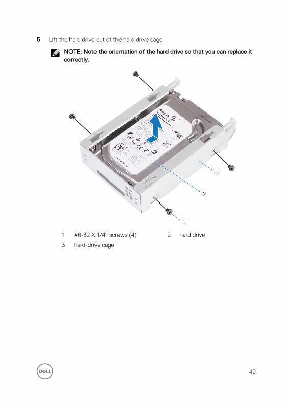
5 Lift the hard drive out of the hard drive cage.
NOTE: Note the orientation of the hard drive so that you can replace it correctly.
1 #6-32 X 1/4'' screws (4) 2 hard drive
3 hard-drive cage
49
Replacing the secondary hard-drive
WARNING: Before working inside your computer, read the safety information that shipped with your computer and follow the steps in Before working inside your computer. After working inside your computer, follow the instructions in After working inside your computer. For more safety best practices, see the Regulatory Compliance home page at www.dell.com/regulatory_compliance.
CAUTION: Hard drives are fragile. Exercise care when handling the hard drive.
Post-requisites
Replace the right-side cover.
Procedure
1 Place the hard drive into the hard-drive cage.
2 Replace the screws that secure the hard drive to the hard-drive cage.
3 Place the hard-drive cage into the hard-drive cage slot in the chassis.
4 Replace the screws that secure the hard-drive cage to the chassis.
5 Connect the data and power cables to the hard drive.
50
Removing the solid-state driveWARNING: Before working inside your computer, read the safety information that shipped with your computer and follow the steps in Before working inside your computer. After working inside your computer, follow the instructions in After working inside your computer. For more safety best practices, see the Regulatory Compliance home page at www.dell.com/regulatory_compliance.
CAUTION: Solid-state drives are fragile. Exercise care when handling the solid-state drive.
CAUTION: To avoid data loss, do not remove the solid-state drive while the computer is in sleep or on state.
Prerequisites
1 Remove the right-side cover.
2 Remove the full-length graphics card (if installed).
Procedure
1 Remove the screw that secures the solid-state drive to the system board.
51

2 Slide and lift the solid-state drive off the system board.
For more information, see “System-board components”.
Figure 15. Removing the solid-state drive
1 solid-state drive 2 solid-state drive slot
3 system board 4 M2x2.5 screw
52
Replacing the solid-state driveWARNING: Before working inside your computer, read the safety information that shipped with your computer and follow the steps in Before working inside your computer. After working inside your computer, follow the instructions in After working inside your computer. For more safety best practices, see the Regulatory Compliance home page at www.dell.com/regulatory_compliance.
CAUTION: Solid-state drives are fragile. Exercise care when handling the solid-state drive.
Procedure
1 Align the notch on the solid-state drive with the tab on the solid-state drive slot.
2 Insert the solid-state drive at a 45-degree angle into the solid-drive drive slot.
For more information, see “System-board components”.
53

3 Replace the screw that secures the solid-state drive to the system board.
Figure 16. Replacing the solid-state drive
1 tab 2 notch
3 solid-state drive slot 4 solid-state drive
5 system board 6 M2 X 2.5 screw
Post-requisites
1 Replace the full-length graphics card (if installed).
54

2 Replace the right-side cover.
55

Removing the power-supply unitWARNING: Before working inside your computer, read the safety information that shipped with your computer and follow the steps in Before working inside your computer. After working inside your computer, follow the instructions in After working inside your computer. For more safety best practices, see the Regulatory Compliance home page at www.dell.com/regulatory_compliance.
WARNING: Lift the power-supply unit carefully as it is designed with a tight hinge without a physical lock. It always stays in the upright position while lifted up.
Prerequisites
Remove the right-side cover.
Procedure
NOTE: Note the routing of all cables as you remove them so that you can reroute them correctly after you replace the power supply.
1 Slide the power-supply unit cage release latches towards the unlock position.
56
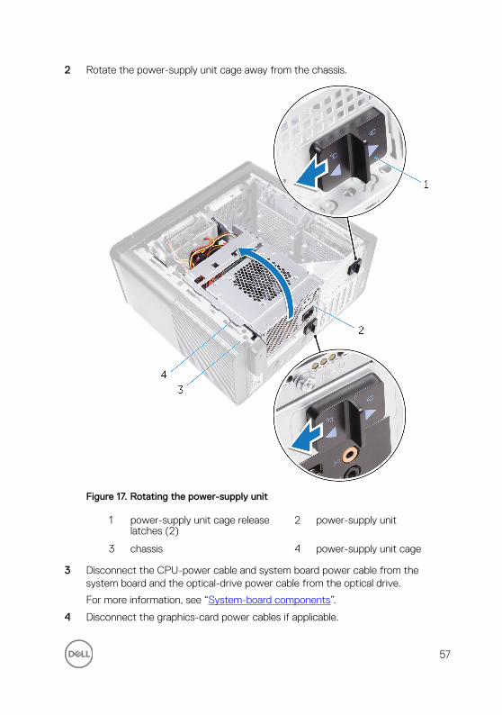
2 Rotate the power-supply unit cage away from the chassis.
Figure 17. Rotating the power-supply unit
1 power-supply unit cage release latches (2)
2 power-supply unit
3 chassis 4 power-supply unit cage
3 Disconnect the CPU-power cable and system board power cable from the system board and the optical-drive power cable from the optical drive.
For more information, see “System-board components”.
4 Disconnect the graphics-card power cables if applicable.
57

5 Remove the system-board power cable from the routing guide on the chassis.
Figure 18. Disconnecting cables
1 optical drive power cable 2 routing guide
3 CPU power cable 4 system board
5 system board power cable
6 Rotate the power-supply unit cage towards the chassis.
7 Disconnect the hard-disk power cable.
NOTE: There could be up to three hard-disk power cables depending on the quantity of hard-disk drive installed.
8 Remove the screws that secure the power-supply bracket to the chassis.
9 Remove the screws that secure the power-supply unit to the chassis.
58

10 Lift the power-supply bracket off the chassis.
11 Lift the power-supply unit off the chassis.
Figure 19. Removing the power supply unit
1 #6-32x1/4'' screws (4) 2 power-supply unit
3 power-supply bracket 4 #6-32x1/4'' screws (2)
5 hard-drive cable
59
Replacing the power-supply unitWARNING: Before working inside your computer, read the safety information that shipped with your computer and follow the steps in Before working inside your computer. After working inside your computer, follow the instructions in After working inside your computer. For more safety best practices, see the Regulatory Compliance home page at www.dell.com/regulatory_compliance.
WARNING: Lift the power-supply unit carefully as it is designed with a tight hinge without a physical lock. It always stays in the upright position while lifted up.
Procedure
1 Place the power supply on the power-supply unit cage.
2 Replace the screws that secure the power-supply unit to the power-supply unit cage.
3 Align the screw holes on the power-supply bracket with the screw holes on the power-supply unit cage.
4 Replace the screws that secure the power supply bracket to the power-supply unit cage.
5 Connect the hard-drive power cable.
6 Rotate the power-supply unit away from the chassis.
7 Connect the CPU-power cable, system-board power cable to the system board and the optical-drive power cable to the optical drive.
For more information, see “System-board components”.
8 Route the system-board power cable through the routing guide on the chassis.
9 Connect the graphics-card power cables if applicable.
10 Rotate the power-supply unit towards the chassis until the unit snaps into place.
11 Slide the power-supply unit cage release latches to their locking positions to lock the release latches.
60

Post-requisites
Replace the right-side cover.
61

Removing the coin-cell batteryWARNING: Before working inside your computer, read the safety information that shipped with your computer and follow the steps in Before working inside your computer. After working inside your computer, follow the instructions in After working inside your computer. For more safety best practices, see the Regulatory Compliance home page at www.dell.com/regulatory_compliance.
CAUTION: Removing the coin-cell battery resets the BIOS setup program’s settings to default. It is recommended that you note the BIOS setup program’s settings before removing the coin-cell battery.
Prerequisites
1 Remove the right-side cover.
2 Follow the procedure from step 1 to step 2 in “Removing the power-supply unit”.
Procedure
1 Using a plastic scribe, press the battery-release lever away from the coin-cell battery until the coin-cell battery pops up.
62
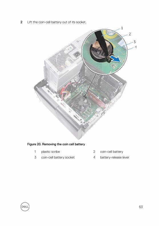
2 Lift the coin-cell battery out of its socket.
Figure 20. Removing the coin cell battery
1 plastic scribe 2 coin-cell battery
3 coin-cell battery socket 4 battery-release lever
63

Replacing the coin-cell batteryWARNING: Before working inside your computer, read the safety information that shipped with your computer and follow the steps in Before working inside your computer. After working inside your computer, follow the instructions in After working inside your computer. For more safety best practices, see the Regulatory Compliance home page at www.dell.com/regulatory_compliance.
Procedure
Insert the coin-cell battery into the battery socket with the positive side facing up, and snap the battery into place.
Post-requisites
1 Follow the procedure from step 9 to step 10 in “Replacing the power-supply unit”.
2 Replace the right-side cover.
64

Removing the graphics cardWARNING: Before working inside your computer, read the safety information that shipped with your computer and follow the steps in Before working inside your computer. After working inside your computer, follow the instructions in After working inside your computer. For more safety best practices, see the Regulatory Compliance home page at www.dell.com/regulatory_compliance.
Prerequisites
NOTE: Your computer will be shipped with either graphics card or full-length graphics card.
1 Remove the right-side cover.
2 Follow the procedure from step 1 to step 2 in “Removing the power-supply unit”.
Procedure
1 Locate the graphics card on the system board and make note of the graphics-card slot (PCI-Express x16).
For more information, see “System-board components”.
65
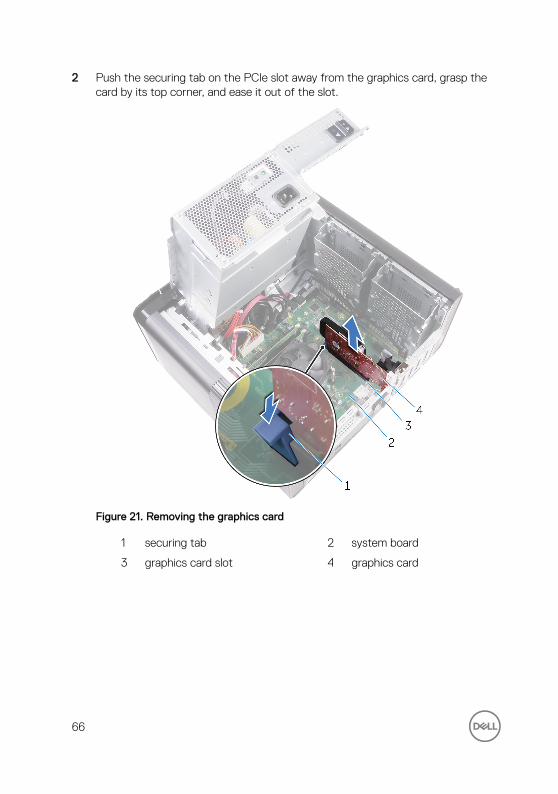
2 Push the securing tab on the PCIe slot away from the graphics card, grasp the card by its top corner, and ease it out of the slot.
Figure 21. Removing the graphics card
1 securing tab 2 system board
3 graphics card slot 4 graphics card
66
Replacing the graphics cardWARNING: Before working inside your computer, read the safety information that shipped with your computer and follow the steps in Before working inside your computer. After working inside your computer, follow the instructions in After working inside your computer. For more safety best practices, see the Regulatory Compliance home page at www.dell.com/regulatory_compliance.
Procedure
1 Locate the PCI-Express x16 card slot on the system board.
For more information, see “System-board components”.
2 Align the notch on the graphics card with the tab on the slot and snap the graphics card in place.
Post-requisites
1 Follow the procedure from step 9 to step 10 in “Replacing the power-supply unit”.
2 Replace the right-side cover.
67

Removing the full-length graphics cards
WARNING: Before working inside your computer, read the safety information that shipped with your computer and follow the steps in Before working inside your computer. After working inside your computer, follow the instructions in After working inside your computer. For more safety best practices, see the Regulatory Compliance home page at www.dell.com/regulatory_compliance.
Prerequisites
NOTE: Your computer will be shipped with either graphics card or full-length graphics card.
1 Remove the right-side cover.
2 Follow the procedure from step 1 to step 2 in “Removing the power-supply unit”.
68

Procedure
1 Lift to release the full-length graphics-card bracket from the chassis.
Figure 22. Removing the full-length graphics-card bracket
1 full-length graphics-card bracket
2 chassis
2 Press the releasing clip on the power-cable connectors and disconnect the power cables from the full-length graphics card.
69

3 Push the securing tab on the PCIe slot away from the full-length graphics card, grasp the card by its top corner, and ease it out of the slot.
Figure 23. Removing the power cable
1 power cables 2 releasing clips (2)
3 full-length graphics card 4 securing tab
70
Replacing the full-length graphics cards
WARNING: Before working inside your computer, read the safety information that shipped with your computer and follow the steps in Before working inside your computer. After working inside your computer, follow the instructions in After working inside your computer. For more safety best practices, see the Regulatory Compliance home page at www.dell.com/regulatory_compliance.
Procedure
1 Align the full-length graphics card with the slot on the system board.
2 Place the card into the slot and press down firmly until the full-length graphics card snaps into place.
3 Connect the power cables to the full-length graphics card.
4 Slide the tab on the full-length graphics-card bracket into the slot on the chassis and snap it into place.
Post-requisites
1 Follow the procedure from step 9 to step 10 in “Replacing the power-supply unit”.
2 Replace the right-side cover.
71

Removing the memory modulesWARNING: Before working inside your computer, read the safety information that shipped with your computer and follow the steps in Before working inside your computer. After working inside your computer, follow the instructions in After working inside your computer. For more safety best practices, see the Regulatory Compliance home page at www.dell.com/regulatory_compliance.
Prerequisites
1 Remove the right-side cover.
2 Follow the procedure from step 1 to step 2 in “Removing the power-supply unit”.
Procedure
1 Locate the memory-module slot on the system board.
For more information, see “System-board components”.
2 Push the securing clips away from the memory module.
72
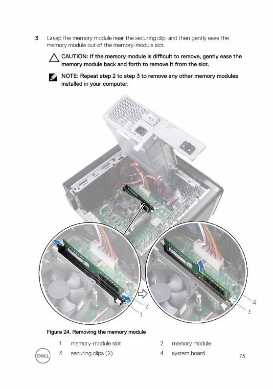
3 Grasp the memory module near the securing clip, and then gently ease the memory module out of the memory-module slot.
CAUTION: If the memory module is difficult to remove, gently ease the memory module back and forth to remove it from the slot.
NOTE: Repeat step 2 to step 3 to remove any other memory modules installed in your computer.
Figure 24. Removing the memory module
1 memory-module slot 2 memory module
3 securing clips (2) 4 system board 73
Replacing the memory modulesWARNING: Before working inside your computer, read the safety information that shipped with your computer and follow the steps in Before working inside your computer. After working inside your computer, follow the instructions in After working inside your computer. For more safety best practices, see the Regulatory Compliance home page at www.dell.com/regulatory_compliance.
Procedure
1 Align the notch on the memory module with the tab on the memory-module slot.
74
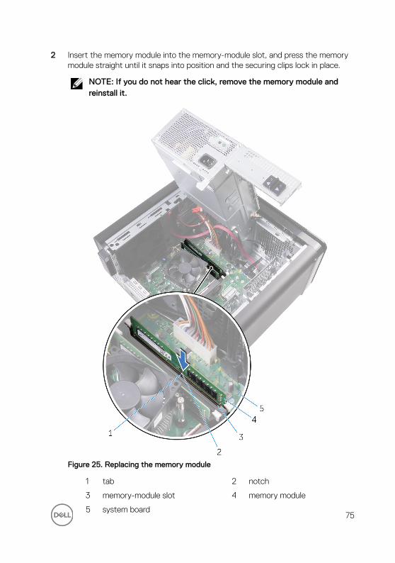
2 Insert the memory module into the memory-module slot, and press the memory module straight until it snaps into position and the securing clips lock in place.
NOTE: If you do not hear the click, remove the memory module and reinstall it.
Figure 25. Replacing the memory module
1 tab 2 notch
3 memory-module slot 4 memory module
5 system board75

NOTE: Use slots DIMM1 and DIMM3 if you need to use two memory modules. For more information, see System-board components.
The following table lists the available memory configuration matrix:Table 2. Memory configuration matrix
ConfigurationSlot
DIMM1 DIMM2 DIMM3 DIMM4
8 GB 4 GB 4 GB
16 GB 8 GB 8 GB
24 GB 4 GB 4 GB 8 GB 8 GB
32 GB 8 GB 8 GB 8 GB 8 GB
64 GB 16 GB 16 GB 16 GB 16 GB
Post-requisites
1 Follow the procedure from step 9 to step 10 in “Replacing the power-supply unit”.
2 Replace the right-side cover.
76

Removing the power-button module
WARNING: Before working inside your computer, read the safety information that shipped with your computer and follow the steps in Before working inside your computer. After working inside your computer, follow the instructions in After working inside your computer. For more safety best practices, see the Regulatory Compliance home page at www.dell.com/regulatory_compliance.
Prerequisites
1 Remove the right-side cover.
2 Remove the optical drive.
3 Remove the front bezel.
4 Remove the top cover.
5 Follow the procedure from step 1 to step 2 in “Removing the power-supply unit”.
Procedure
NOTE: Note the routing of the cable as you remove it so that you can reroute it correctly after you replace the power-button module.
1 Disconnect the power-button module cable from the system board.
For more information, see “System-board components”.
2 Note the power-button module cable routing and remove the cable from the routing guides next to the system board on the chassis.
3 Remove the screw that secures the power-button module and lift the power-button module from the chassis.
77
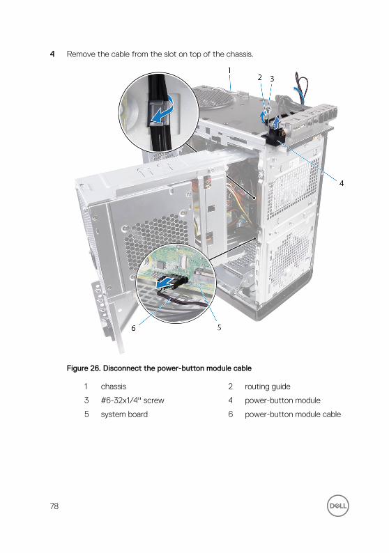
4 Remove the cable from the slot on top of the chassis.
Figure 26. Disconnect the power-button module cable
1 chassis 2 routing guide
3 #6-32x1/4'' screw 4 power-button module
5 system board 6 power-button module cable
78

Replacing the power-button module
WARNING: Before working inside your computer, read the safety information that shipped with your computer and follow the steps in Before working inside your computer. After working inside your computer, follow the instructions in After working inside your computer. For more safety best practices, see the Regulatory Compliance home page at www.dell.com/regulatory_compliance.
Procedure
1 Route the cable through the slot on the top of the chassis.
2 Align the screw hole on the power-button module with the screw hole on the chassis.
3 Replace the screw that secures the power-button module to the top chassis.
4 Route the power-button module cable through the routing guides on the chassis.
5 Connect the power-button module cable to the system board.
For more information, see “System-board components”.
Post-requisites
1 Follow the procedure from step 9 to step 10 in “Replacing the power-supply unit”.
2 Replace the top cover.
3 Replace the front bezel.
4 Replace the optical drive.
5 Replace the right-side cover.
79

Removing the top I/O-panelWARNING: Before working inside your computer, read the safety information that shipped with your computer and follow the steps in Before working inside your computer. After working inside your computer, follow the instructions in After working inside your computer. For more safety best practices, see the Regulatory Compliance home page at www.dell.com/regulatory_compliance.
Prerequisites
1 Remove the right-side cover.
2 Remove the front bezel.
3 Remove the top cover.
4 Follow the procedure from step 1 to step 2 in “Removing the power-supply unit”.
Procedure
1 Disconnect the top I/O-panel cables from the system board.
For more information, see "System-board components”.
2 Note the I/O-panel cables routing and remove them from the routing guides next to the system board on the chassis.
80
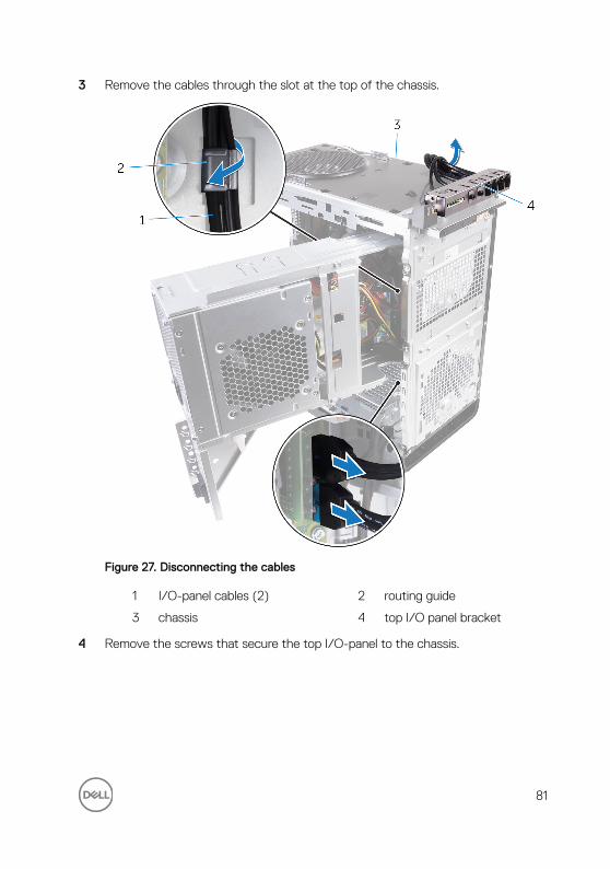
3 Remove the cables through the slot at the top of the chassis.
Figure 27. Disconnecting the cables
1 I/O-panel cables (2) 2 routing guide
3 chassis 4 top I/O panel bracket
4 Remove the screws that secure the top I/O-panel to the chassis.
81
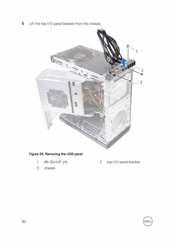
5 Lift the top I/O-panel bracket from the chassis.
Figure 28. Removing the USB panel
1 #6-32x1/4'' (4) 2 top I/O-panel bracket
3 chassis
82
Replacing the top I/O-panelWARNING: Before working inside your computer, read the safety information that shipped with your computer and follow the steps in Before working inside your computer. After working inside your computer, follow the instructions in After working inside your computer. For more safety best practices, see the Regulatory Compliance home page at www.dell.com/regulatory_compliance.
Procedure
1 Align the screw holes on the top I/O-panel with the screw holes on the chassis.
2 Replace the screws that secure the top I/O-panel to the top chassis.
3 Route the I/O-panel cables through the routing guides on the chassis.
4 Connect the top I/O-panel cables to the system board.
For more information, see "System-board components".
Post-requisites
1 Replace the top cover.
2 Replace the front bezel.
3 Follow the procedure from step 9 to step 10 in “Replacing the power-supply unit”.
4 Replace the right-side cover.
83
Removing blower and heat-sink assembly
WARNING: Before working inside your computer, read the safety information that shipped with your computer and follow the steps in Before working inside your computer. After working inside your computer, follow the instructions in After working inside your computer. For more safety best practices, see the Regulatory Compliance home page at www.dell.com/regulatory_compliance.
WARNING: The heat sink may become hot during normal operation. Allow sufficient time for the heat sink to cool before you touch it.
CAUTION: For maximum cooling of the processor, do not touch the heat transfer areas on the heat sink. The oils in your skin can reduce the heat transfer capability of the thermal grease.
Prerequisites
1 Remove the right-side cover.
2 Follow the procedure from step 1 to step 2 in “Removing the power-supply unit”.
Procedure
1 Remove the screws that secure the blower to the heat-sink assembly.
84
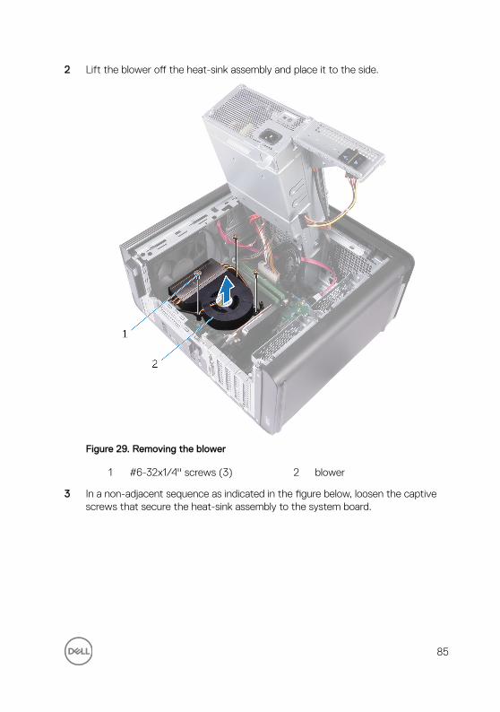
2 Lift the blower off the heat-sink assembly and place it to the side.
Figure 29. Removing the blower
1 #6-32x1/4'' screws (3) 2 blower
3 In a non-adjacent sequence as indicated in the figure below, loosen the captive screws that secure the heat-sink assembly to the system board.
85
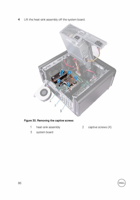
4 Lift the heat-sink assembly off the system board.
Figure 30. Removing the captive screws
1 heat-sink assembly 2 captive screws (4)
3 system board
86

5 Disconnect the blower cable from the system board.
For more information, see “System-board components”.
Figure 31. Removing the blower cable
1 system board 2 blower cable
3 blower
87

Replacing blower and heat-sink assembly
WARNING: Before working inside your computer, read the safety information that shipped with your computer and follow the steps in Before working inside your computer. After working inside your computer, follow the instructions in After working inside your computer. For more safety best practices, see the Regulatory Compliance home page at www.dell.com/regulatory_compliance.
Procedure
CAUTION: If either the processor or the heat-sink assembly is replaced, use the thermal grease provided in the kit to make sure that thermal conductivity is achieved.
NOTE: The original thermal grease can be reused if the original processor and heat-sink assembly are reinstalled together.
1 Connect the blower cable to the system board.
For more information, see “System-board components”.
2 Place the heat-sink assembly over the processor.
3 Align the captive screws on the heat-sink assembly with the screw holes on the system board.
4 In a non-adjacent sequence, tighten the captive screws that secure the heat-sink assembly to the system board.
5 Place the blower over the heat-sink assembly.
6 Align the screw holes on the blower to the screw holes on the heat-sink assembly.
7 Replace the screws that secure the blower to the heat-sink assembly.
Post-requisites
1 Follow the procedure from step 9 to step 10 in “Replacing the power-supply unit”.
88

2 Replace the right-side cover.
89

Removing the VR heat sinkWARNING: Before working inside your computer, read the safety information that shipped with your computer and follow the steps in Before working inside your computer. After working inside your computer, follow the instructions in After working inside your computer. For more safety best practices, see the Regulatory Compliance home page at www.dell.com/regulatory_compliance.
WARNING: The heat sink may become hot during normal operation. Allow sufficient time for the heat sink to cool before you touch it.
CAUTION: For maximum cooling of the processor, do not touch the heat transfer areas on the heat sink. The oils in your skin can reduce the heat transfer capability of the thermal grease.
Prerequisites
1 Remove the right-side cover.
2 Follow the procedure from step 1 to step 2 in “Removing the power-supply unit”.
3 Remove the blower and heat-sink assembly.
Procedure
1 Loosen the captive screws that secure the VR heat sink to the system board.
90

2 Lift the VR heat sink from the system board.
Figure 32. Removing the VR heat sink
91

Replacing the VR heat sinkWARNING: Before working inside your computer, read the safety information that shipped with your computer and follow the steps in Before working inside your computer. After working inside your computer, follow the instructions in After working inside your computer. For more safety best practices, see the Regulatory Compliance home page at www.dell.com/regulatory_compliance.
Procedure
1 Align and place the VR heat sink on the system board.
2 Tighten the captive screws that secure the VR heat sink to the system board.
Post-requisites
1 Replace the blower and heat-sink assembly.
2 Follow the procedure from step 9 to step 10 in “Replacing the power-supply unit”.
3 Replace the right-side cover.
92
Removing the processor fan and heat-sink assembly
WARNING: Before working inside your computer, read the safety information that shipped with your computer and follow the steps in Before working inside your computer. After working inside your computer, follow the instructions in After working inside your computer. For more safety best practices, see the Regulatory Compliance home page at www.dell.com/regulatory_compliance.
WARNING: The heat sink may become hot during normal operation. Allow sufficient time for the heat sink to cool before you touch it.
CAUTION: For maximum cooling of the processor, do not touch the heat transfer areas on the heat sink. The oils in your skin can reduce the heat transfer capability of the thermal grease.
Prerequisites
1 Remove the right-side cover.
2 Follow the procedure from step 1 to step 2 in “Removing the power-supply unit”.
Procedure
1 Disconnect the processor-fan cable from the system board.
For more information, see “System-board components”.
2 In a non-adjacent sequence as indicated in the figure below, loosen the captive screws that secure the processor fan and heat-sink assembly to the system board.
93
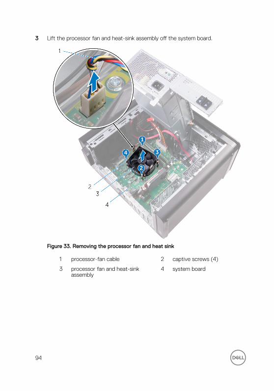
3 Lift the processor fan and heat-sink assembly off the system board.
Figure 33. Removing the processor fan and heat sink
1 processor-fan cable 2 captive screws (4)
3 processor fan and heat-sink assembly
4 system board
94

Replacing the processor fan and heat-sink assembly
WARNING: Before working inside your computer, read the safety information that shipped with your computer and follow the steps in Before working inside your computer. After working inside your computer, follow the instructions in After working inside your computer. For more safety best practices, see the Regulatory Compliance home page at www.dell.com/regulatory_compliance.
Procedure
CAUTION: If either the processor or the heat-sink assembly is replaced, use the thermal grease provided in the kit to make sure that thermal conductivity is achieved.
NOTE: The original thermal grease can be reused if the original processor and heat-sink assembly are reinstalled together.
1 Place the processor fan and heat-sink assembly over the processor.
2 Align the captive screws on the processor fan heat-sink assembly with the screw holes on the system board.
3 In a non-adjacent sequence, tighten the captive screws that secure the processor fan and heat-sink assembly to the system board.
4 Connect the processor-fan cable to the system board.
For more information, see “System-board components”.
Post-requisites
1 Follow the procedure from step 9 to step 10 in “Replacing the power-supply unit”.
2 Replace the right-side cover.
95

Removing the chassis fanWARNING: Before working inside your computer, read the safety information that shipped with your computer and follow the steps in Before working inside your computer. After working inside your computer, follow the instructions in After working inside your computer. For more safety best practices, see the Regulatory Compliance home page at www.dell.com/regulatory_compliance.
Prerequisites
1 Remove the right-side cover.
2 Follow the procedure from step 1 to step 2 in “Removing the power-supply unit”.
3 Remove the blower and heat-sink assembly. (if installed)
4 Remove the VR heat sink. (if installed)
Procedure
1 Remove the chassis-fan cable from the routing guide on the chassis-fan bracket.
2 Disconnect the chassis-fan cable from the system board.
For more information, see “System-board components”.
3 Remove the screw that secures the chassis-fan bracket to the chassis.
4 Slide the chassis-fan assembly towards the front of the computer to release the fan from the chassis.
96

5 Lift the chassis-fan assembly off the chassis.
Figure 34. Removing the chassis fan
1 routing guide 2 chassis-fan bracket
3 #6-32x1/4'' screw 4 chassis
5 chassis-fan cable 6 system board
7 chassis fan
6 Push the rubber grommets through the holes at each corner of the fan to release the chassis-fan from the bracket.
97
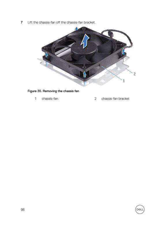
7 Lift the chassis-fan off the chassis-fan bracket.
Figure 35. Removing the chassis fan
1 chassis-fan 2 chassis-fan bracket
98
Replacing the chassis fanWARNING: Before working inside your computer, read the safety information that shipped with your computer and follow the steps in Before working inside your computer. After working inside your computer, follow the instructions in After working inside your computer. For more safety best practices, see the Regulatory Compliance home page at www.dell.com/regulatory_compliance.
Procedure
1 Align the holes on the chassis fan with the rubber grommets on the chassis-fan bracket.
NOTE: Align the orientation of the chassis-fan bracket as indicated on the bracket to ensure that the chassis fan is secured to the computer.
2 Insert the ends of the rubber grommets through the holes at each corner of the fan.
3 Align the grommets in the fan with the holes at each corner of the chassis fan bracket and pull through until they snap into place.
4 Route the chassis-fan cable through the routing guide on the bracket.
5 Align the tabs on the chassis-fan bracket with the slots on the chassis and slide the fan into position.
6 Align the screw hole on the chassis-fan bracket with the screw hole on the chassis.
7 Replace the screw that secures the chassis-fan bracket to the chassis.
8 Route the chassis-fan cable through the routing guide on the bracket.
9 Connect the chassis-fan cable to the system board.
For more information, see “System-board components”.
Post-requisites
1 Replace the VR heat sink. (if installed)
2 Replace the blower and heat-sink assembly. (if installed)
99

3 Follow the procedure from step 9 to step 10 in “Replacing the power-supply unit”.
4 Replace the right-side cover.
100
Removing the processorWARNING: Before working inside your computer, read the safety information that shipped with your computer and follow the steps in Before working inside your computer. After working inside your computer, follow the instructions in After working inside your computer. For more safety best practices, see the Regulatory Compliance home page at www.dell.com/regulatory_compliance.
Prerequisites
1 Remove the right-side cover.
2 Follow the procedure from step 1 to step 2 in “Removing the power-supply unit”.
3 Remove the processor fan and heat-sink assembly.
4 Remove the blower and heat-sink assembly. (if installed)
Procedure
1 Press the processor release-lever down and then pull it outwards to release it from the securing tab.
2 Extend the processor release-lever completely to open the processor cover.
101
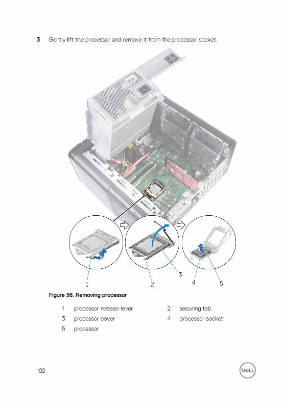
3 Gently lift the processor and remove it from the processor socket.
Figure 36. Removing processor
1 processor release-lever 2 securing tab
3 processor cover 4 processor socket
5 processor
102

Replacing the processorWARNING: Before working inside your computer, read the safety information that shipped with your computer and follow the steps in Before working inside your computer. After working inside your computer, follow the instructions in After working inside your computer. For more safety best practices, see the Regulatory Compliance home page at www.dell.com/regulatory_compliance.
CAUTION: If either the processor or the heat sink is replaced, use the thermal grease provided in the kit to ensure that thermal conductivity is achieved.
NOTE: A new processor ships with a thermal pad in the package. In some cases, the processor may ship with the thermal pad attached to it.
Procedure
1 Ensure that the release lever on the processor socket is fully extended in the open position.
CAUTION: The pin-1 corner of the processor has a triangle that aligns with the triangle on the pin-1 corner on the processor socket. When the processor is properly seated, all four corners are aligned at the same height. If one or more corners of the processor are higher than the others, the processor is not seated properly.
2 Align the pin-1 corner on the processor with the pin-1 corner on the processor socket, and then place the processor in the processor socket.
3 When the processor is fully seated in the socket, close the processor cover.
103

4 Pivot the release-lever down and place it under the tab on the processor cover.
Figure 37. Replacing processor
1 processor socket 2 processor
3 securing tab 4 processor cover
5 release lever
104

Post-requisites
1 Replace the blower and heat-sink assembly. (if installed)
2 Replace the processor fan and heat-sink assembly.
3 Follow the procedure from step 9 to step 10 in “Replacing the power-supply unit”.
4 Replace the right-side cover.
105

Removing the wireless cardWARNING: Before working inside your computer, read the safety information that shipped with your computer and follow the steps in Before working inside your computer. After working inside your computer, follow the instructions in After working inside your computer. For more safety best practices, see the Regulatory Compliance home page at www.dell.com/regulatory_compliance.
Prerequisites
1 Remove the right-side cover.
2 Follow the procedure from step 1 to step 2 in “Removing the power-supply unit”.
Procedure
1 Locate the wireless-card slot on the system board.
For more information, see “System-board components”.
2 Remove the screw that secures the wireless-card bracket to the wireless card and the system board.
3 Remove the wireless-card bracket and disconnect the antenna cables from the wireless card.
106

4 Slide and lift the wireless card off the system board.
Figure 38. Removing the wireless card
1 M2x2.5 screw 2 wireless-card bracket
3 antenna cables (2) 4 system board
5 wireless-card slot 6 wireless card
107
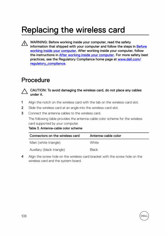
Replacing the wireless cardWARNING: Before working inside your computer, read the safety information that shipped with your computer and follow the steps in Before working inside your computer. After working inside your computer, follow the instructions in After working inside your computer. For more safety best practices, see the Regulatory Compliance home page at www.dell.com/regulatory_compliance.
Procedure
CAUTION: To avoid damaging the wireless card, do not place any cables under it.
1 Align the notch on the wireless card with the tab on the wireless-card slot.
2 Slide the wireless card at an angle into the wireless-card slot.
3 Connect the antenna cables to the wireless card.
The following table provides the antenna-cable color scheme for the wireless card supported by your computer.Table 3. Antenna-cable color scheme
Connectors on the wireless card Antenna-cable color
Main (white triangle) White
Auxiliary (black triangle) Black
4 Align the screw hole on the wireless-card bracket with the screw hole on the wireless card and the system board.
108
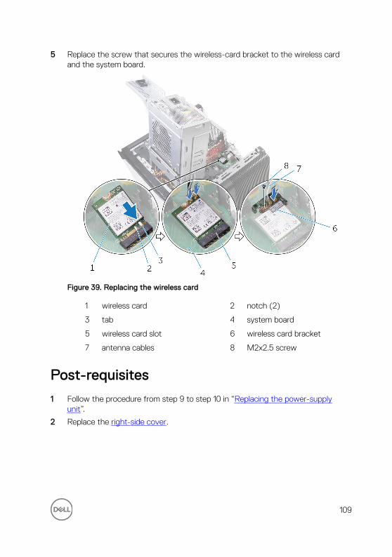
5 Replace the screw that secures the wireless-card bracket to the wireless card and the system board.
Figure 39. Replacing the wireless card
1 wireless card 2 notch (2)
3 tab 4 system board
5 wireless card slot 6 wireless card bracket
7 antenna cables 8 M2x2.5 screw
Post-requisites
1 Follow the procedure from step 9 to step 10 in “Replacing the power-supply unit”.
2 Replace the right-side cover.
109

Removing the antennaWARNING: Before working inside your computer, read the safety information that shipped with your computer and follow the steps in Before working inside your computer. After working inside your computer, follow the instructions in After working inside your computer. For more safety best practices, see the Regulatory Compliance home page at www.dell.com/regulatory_compliance.
Prerequisites
1 Remove the right-side cover.
2 Follow the procedure from step 1 to step 2 in “Removing the power-supply unit”.
3 Remove the top cover.
4 Follow the procedure from step 1 to step 4 in Removing the wireless card.
Procedure
1 Open the securing clip which secures the antenna cable to the chassis.
2 Remove the cables from the routing guide through the slot on the top of the chassis.
110

3 Note the antenna-cable routing and remove the antenna cables from the routing guides on the chassis.
Figure 40. Disconnecting the antenna cables
1 antenna cable 2 securing clip
3 chassis 4 routing guide
111

4 Using a plastic scribe, pry the antenna off the chassis.
Figure 41. Removing the antenna
1 plastic scribe 2 antenna (2)
3 routing guide 4 chassis
5 antenna cables
112
Replacing the antennaWARNING: Before working inside your computer, read the safety information that shipped with your computer and follow the steps in Before working inside your computer. After working inside your computer, follow the instructions in After working inside your computer. For more safety best practices, see the Regulatory Compliance home page at www.dell.com/regulatory_compliance.
Procedure
1 Adhere the antenna to the chassis.
2 Route the antenna cables through the slot on the top of the chassis.
3 Route the antenna cables through the routing guides on the chassis.
4 Secure the antenna cables to the chassis using the securing clip.
Post-requisites
1 Follow the procedure from step 3 to step 5 in “Replacing the wireless card”.
2 Replace the top cover.
3 Follow the procedure from step 9 to step 10 in “Replacing the power-supply unit”.
4 Replace the right-side cover.
113
Removing the system boardWARNING: Before working inside your computer, read the safety information that shipped with your computer and follow the steps in Before working inside your computer. After working inside your computer, follow the instructions in After working inside your computer. For more safety best practices, see the Regulatory Compliance home page at www.dell.com/regulatory_compliance.
NOTE: Your computer’s Service Tag is stored in the system board. You must enter the Service Tag in the BIOS setup program after you replace the system board.
NOTE: Replacing the system board removes any changes you have made to the BIOS using the BIOS setup program. You must make the appropriate changes again after you replace the system board.
NOTE: Before disconnecting the cables from the system board, note the location of the connectors so that you can reconnect the cables correctly after you replace the system board.
Prerequisites
1 Remove the right-side cover.
2 Follow the procedure from step 1 to step 2 in “Removing the power-supply unit”.
3 Remove the memory modules.
4 Remove the graphics card.
5 Remove the solid-state drive.
6 Remove the wireless card.
7 Remove the processor fan and heat sink assembly.
8 Remove the processor.
Procedure
1 Disconnect all the cables connected to the system board.
For more information, see “System-board components”.
2 Make note of the cable routing and remove the cables from the routing guides.
114

3 Remove the screws that secure the system board to the chassis.
4 Lift the system board at an angle and remove it from the computer.
Figure 42. Removing the system board
1 system board 2 #6-32x1/4'' screws (8)
3 chassis
115

Replacing the system boardWARNING: Before working inside your computer, read the safety information that shipped with your computer and follow the steps in Before working inside your computer. After working inside your computer, follow the instructions in After working inside your computer. For more safety best practices, see the Regulatory Compliance home page at www.dell.com/regulatory_compliance.
NOTE: Your computer’s Service Tag is stored in the system board. You must enter the Service Tag in the BIOS setup program after you replace the system board.
NOTE: Replacing the system board removes any changes you have made to the BIOS using the BIOS setup program. You must make the appropriate changes again after you replace the system board.
Procedure
1 Slide the I/O ports on the system board into the slots on the chassis and align the screw holes on the system board with the screw holes on the chassis.
2 Replace the screws that secure the system board to the chassis.
3 Route and connect the cables that you disconnected from the system board.
For more information, see “System-board components.”
Post-requisites
1 Replace the processor.
2 Replace the processor fan and heat sink assembly.
3 Replace the wireless card.
4 Replace the solid-state drive.
5 Replace the graphics card.
6 Replace the memory modules.
7 Follow the procedure from step 9 to step 10 in “Replacing the power-supply unit”.
8 Replace the right-side cover.
116

Downloading drivers
Downloading the audio driver
1 Turn on your computer.
2 Go to www.dell.com/support.
3 Click or tap Product support, enter the Service Tag of your computer, and then click or tap Submit.
NOTE: If you do not have the Service Tag, use the auto-detect feature or manually browse for your computer model.
4 Click or tap Drivers & downloads → Find it myself.
5 Scroll down the page and expand Audio.
6 Click or tap Download to download the audio driver for your computer.
7 After the download is complete, navigate to the folder where you saved the audio driver file.
8 Double-click or double-tap the audio driver file icon and follow the instructions on the screen to install the driver.
Downloading the graphics driver
1 Turn on your computer.
2 Go to www.dell.com/support.
3 Click or tap Product support enter the Service Tag of your computer, and then click or tap Submit.
NOTE: If you do not have the Service Tag, use the auto-detect feature or manually browse for your computer model.
4 Click or tap Drivers & downloads → Find it myself.
5 Scroll down the page and expand Video.
6 Click or tap Download to download the graphics driver for your computer.
7 After the download is complete, navigate to the folder where you saved the graphics driver file.
8 Double-click or double-tap the graphics driver file icon and follow the instructions on the screen.
117
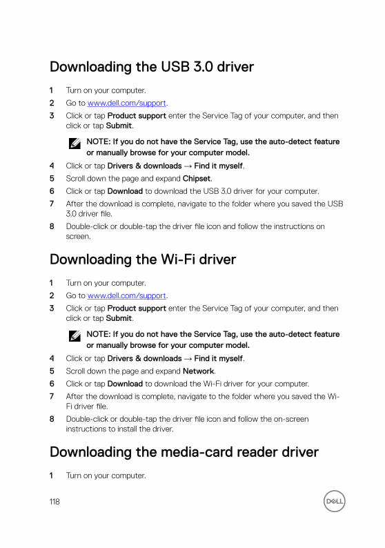
Downloading the USB 3.0 driver
1 Turn on your computer.
2 Go to www.dell.com/support.
3 Click or tap Product support enter the Service Tag of your computer, and then click or tap Submit.
NOTE: If you do not have the Service Tag, use the auto-detect feature or manually browse for your computer model.
4 Click or tap Drivers & downloads → Find it myself.
5 Scroll down the page and expand Chipset.
6 Click or tap Download to download the USB 3.0 driver for your computer.
7 After the download is complete, navigate to the folder where you saved the USB 3.0 driver file.
8 Double-click or double-tap the driver file icon and follow the instructions on screen.
Downloading the Wi-Fi driver
1 Turn on your computer.
2 Go to www.dell.com/support.
3 Click or tap Product support enter the Service Tag of your computer, and then click or tap Submit.
NOTE: If you do not have the Service Tag, use the auto-detect feature or manually browse for your computer model.
4 Click or tap Drivers & downloads → Find it myself.
5 Scroll down the page and expand Network.
6 Click or tap Download to download the Wi-Fi driver for your computer.
7 After the download is complete, navigate to the folder where you saved the Wi-Fi driver file.
8 Double-click or double-tap the driver file icon and follow the on-screen instructions to install the driver.
Downloading the media-card reader driver
1 Turn on your computer.
118

2 Go to www.dell.com/support.
3 Click Product support, enter the Service Tag of your computer, and then click Submit.
NOTE: If you do not have the Service Tag, use the auto-detect feature or manually browse for your computer model.
4 Click Drivers & downloads → Find it myself.
5 Scroll down the page and expand Chipset.
6 Click Download to download the media-card reader driver for your computer.
7 After the download is complete, navigate to the folder where you saved the card reader driver file.
8 Double-click the card reader driver file icon and follow the instructions on the screen.
Downloading the chipset driver
1 Turn on your computer.
2 Go to www.dell.com/support.
3 Click or tap Product support, enter the Service Tag of your computer, and then click or tap Submit.
NOTE: If you do not have the Service Tag, use the auto-detect feature or manually browse for your computer model.
4 Click or tap Drivers & downloads → Find it myself.
5 Scroll down the page and expand Chipset.
6 Click or tap Download to download the chipset driver for your computer.
7 After the download is complete, navigate to the folder where you saved the chipset driver file.
8 Double-click or double-tap the chipset driver file icon and follow the instructions on the screen.
Downloading the network driver
1 Turn on your computer.
2 Go to www.dell.com/support.
119

3 Click Product support enter the Service Tag of your computer and click Submit.
NOTE: If you do not have the Service Tag, use the auto-detect feature or manually browse for your computer model.
4 Click Drivers & downloads → Find it myself.
5 Scroll down the page and expand Network.
6 Click Download to download the network driver for your computer.
7 Save the file, and after the download is complete, navigate to the folder where you saved the network driver file.
8 Double-click the network driver file icon and follow the instructions on screen.
120

System setupNOTE: Depending on the computer and its installed devices, the items listed in this section may or may not be displayed.
Boot Sequence
Boot Sequence allows you to bypass the System Setup–defined boot device order and boot directly to a specific device (for example: optical drive or hard drive). During the Power-on Self Test (POST), when the Dell logo appears, you can:
• Access System Setup by pressing F2 key
• Bring up the one-time boot menu by pressing F12 key
The one-time boot menu displays the devices that you can boot from including the diagnostic option. The boot menu options are:
• Removable Drive (if available)
• STXXXX Drive
NOTE: XXX denotes the SATA drive number.
• Optical Drive (if available)
• SATA Hard Drive (if available)
• Diagnostics
NOTE: Choosing Diagnostics, will display the ePSA diagnostics screen.
The boot sequence screen also displays the option to access the System Setup screen.
Navigation keys
NOTE: For most of the System Setup options, changes that you make are recorded but do not take effect until you restart the system.
121

Keys Navigation
Up arrow Moves to the previous field.
Down arrow Moves to the next field.
Enter Selects a value in the selected field (if applicable) or follow the link in the field.
Spacebar Expands or collapses a drop‐down list, if applicable.
Tab Moves to the next focus area.
NOTE: For the standard graphics browser only.
Esc Moves to the previous page until you view the main screen. Pressing Esc in the main screen displays a message that prompts you to save any unsaved changes and restarts the system.
BIOS overview
The BIOS manages data flow between the computer's operating system and attached devices such as hard disk, video adapter, keyboard, mouse, and printer.
Entering BIOS setup program
1 Turn on (or restart) your computer.
2 During POST, when the DELL logo is displayed, watch for the F2 prompt to appear, and then press F2 immediately.
NOTE: The F2 prompt indicates that the keyboard is initialized. This prompt can appear very quickly, so you must watch for it, and then press F2. If you press F2 before the F2 prompt, this keystroke is lost. If you wait too long and the operating system logo appears, continue to wait until you see the desktop. Then, turn off your computer and try again.
122

System Setup Options
NOTE: Depending on your computer and its installed devices, the items listed in this section may or may not appear.
Table 4. System setup options—Main menu
Main
System Time Displays the current time in hh:mm:ss format.
System Date Displays the current date in mm/dd/yyyy format.
BIOS Version Displays the BIOS version number.
Product Name Displays the product name.
Service Tag Allows you to enter the service tag of your computer.
Asset Tag Displays the asset tag of your computer.
CPU Type Displays the processor type
CPU Speed Displays the speed of the processor.
CPU ID Displays the processor identification code.
CPU Cache
L1 Cache Displays the processor L1 cache size.
L2 Cache Displays the processor L2 cache size.
L3 Cache Displays the processor L3 cache size.
First HDD Displays the type of hard drive installed.
SATA ODD Displays the type of optical drive installed.
M.2 PCIe SSD Displays the type of SSD installed.
123

Table 5. System setup options—Advanced menu
Advanced
Advanced BIOS Features
Intel SpeedStep Technology Allows you to enable or disable Intel Speedstep Technology. Default: Enabled.
NOTE: If enabled, the processor clock speed and core voltage are adjusted dynamically based on the processor load.
Virtualization Allows you to enable or disable the Intel Virtualization technology.
Default: Enabled
VT for Direct I/O Allows you to enable or disable Intel Virtualization Technology feature for the Direct I/O.
Default: Enabled
SATA Operation Allows you to configure the operating mode of the integrated SATA hard drive controller.
Intel Ready Mode Technology Allows you to enable or disable the Intel Ready Mode Technology.
Default: Enabled
Intel Software Guard Extensions Allows you to enable or disable Intel Software Guard Extensions.
BIOS Recovery from Hard Drive Allows you to enable or disable BIOS Recovery from hard drive.
Default: Enabled
BIOS Auto-Recovery BIOS auto-recovery automatically recovers BIOS without user actions.
Default: Disabled
Always Perform Integrity Check Allows you to enable or disable Integrity check.
Default: Disabled
USB Configuration
124

Advanced
Front USB Ports Allows you to enable or disable the front USB ports.
Rear USB Ports Allows you to enable or disable the rear USB ports.
Power Options
Numlock Key Allows you to set the status of the Num Lock key during boot to On or Off.
Wake Up by Integrated LAN Allow the computer to be powered on by special LAN signals.
AC Recovery Sets what action the computer takes when power is restored.
Deep Sleep Control Allows you to define the controls when Deep Sleep is enabled.
USB Wake Support (S3) Allows you to enable the USB devices to wake the computer from Standby.
USB PowerShare (S4/S5) Allows you to charge external devices.
USB PowerShare Wake Support (S4/S5)
Allows you to enable USB devices to wake the computer from S4/S5.
Auto Power On
Auto Power On Mode Allows you to set the computer to turn on automatically every day or on a preselected date. This option can be configured only if the Auto Power On mode is set to Enabled Everyday or Selected Day.
Auto Power On Date Allows you to set the date on which the computer must turn on automatically. This option can be configured only if the Auto Power On mode is set to Enabled 1 to 31.
Auto Power On Time Allows you to set the time at which the computer must turn on automatically. This option can be configured only if the
125
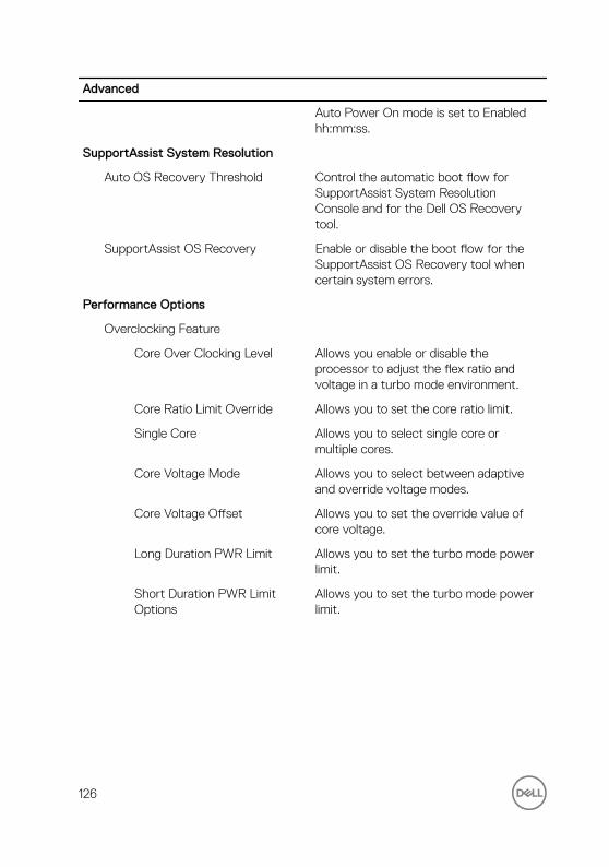
Advanced
Auto Power On mode is set to Enabled hh:mm:ss.
SupportAssist System Resolution
Auto OS Recovery Threshold Control the automatic boot flow for SupportAssist System Resolution Console and for the Dell OS Recovery tool.
SupportAssist OS Recovery Enable or disable the boot flow for the SupportAssist OS Recovery tool when certain system errors.
Performance Options
Overclocking Feature
Core Over Clocking Level Allows you enable or disable the processor to adjust the flex ratio and voltage in a turbo mode environment.
Core Ratio Limit Override Allows you to set the core ratio limit.
Single Core Allows you to select single core or multiple cores.
Core Voltage Mode Allows you to select between adaptive and override voltage modes.
Core Voltage Offset Allows you to set the override value of core voltage.
Long Duration PWR Limit Allows you to set the turbo mode power limit.
Short Duration PWR Limit Options
Allows you to set the turbo mode power limit.
126

Table 6. System setup options—Security menu
Security
Unlock setup Displays if the setup status is unlocked.
Admin Password Status Displays whether the admin password is set.
System Password Status Displays whether the system password is set.
HDD Password Status Displays if the hard drive password is set.
Admin Password Displays the admin password.
System Password Displays the system password.
HDD Password Displays the hard drive password.
Password Change Allows you to permit or deny system password or HDD password changes. Default: Permitted
Computrace Enable or disable the BIOS module interface of the optional Computrace Service from Absolute Software.
Firmware TPM Enable or disable the firmware TPM.
Default: Enabled.
UEFI Firmware Capsule Updates Enable or disable BIOS updates through UEFI capsule update packages.
Default: Enabled.
Table 7. System setup options—Boot menu
Boot
Boot List Option Displays the available boot devices.
File Browser Add Boot Option Allows you to set the boot path in the boot option list.
File Browser Del Boot Option Allows you to delete the boot path in the boot option list.
127
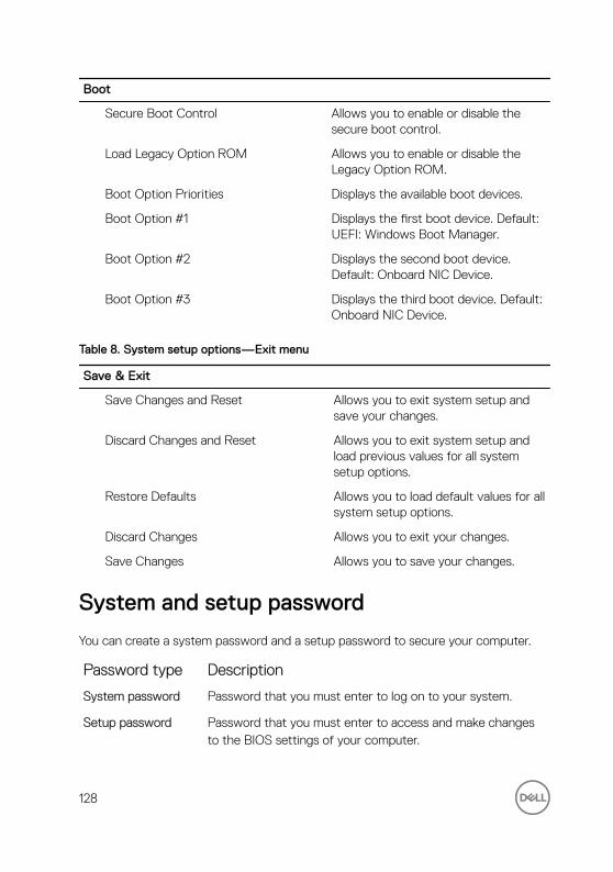
Boot
Secure Boot Control Allows you to enable or disable the secure boot control.
Load Legacy Option ROM Allows you to enable or disable the Legacy Option ROM.
Boot Option Priorities Displays the available boot devices.
Boot Option #1 Displays the first boot device. Default: UEFI: Windows Boot Manager.
Boot Option #2 Displays the second boot device. Default: Onboard NIC Device.
Boot Option #3 Displays the third boot device. Default: Onboard NIC Device.
Table 8. System setup options—Exit menu
Save & Exit
Save Changes and Reset Allows you to exit system setup and save your changes.
Discard Changes and Reset Allows you to exit system setup and load previous values for all system setup options.
Restore Defaults Allows you to load default values for all system setup options.
Discard Changes Allows you to exit your changes.
Save Changes Allows you to save your changes.
System and setup password
You can create a system password and a setup password to secure your computer.
Password type Description
System password Password that you must enter to log on to your system.
Setup password Password that you must enter to access and make changes to the BIOS settings of your computer.
128

CAUTION: The password features provide a basic level of security for the data on your computer.
CAUTION: Anyone can access the data stored on your computer if it is not locked and left unattended.
NOTE: System and setup password feature is disabled.
Assigning a system password and setup password
You can assign a new System Password only when the status is in Not Set.To enter the system setup, press F2 immediately after a power-on or re-boot.
1 In the System BIOS or System Setup screen, select Security and press Enter.
The Security screen is displayed.
2 Select System Password and create a password in the Enter the new password field.
Use the following guidelines to assign the system password:
– A password can have up to 32 characters.
– The password can contain the numbers 0 through 9.
– Only lower case letters are valid, upper case letters are not allowed.
– Only the following special characters are allowed: space, (”), (+), (,), (-), (.), (/), (;), ([), (\), (]), (`).
3 Type the system password that you entered earlier in the Confirm new password field and click OK.
4 Press Esc and a message prompts you to save the changes.
5 Press Y to save the changes.
The computer reboots.
Deleting or changing an existing system and or setup password
Ensure that the Password Status is Unlocked (in the System Setup) before attempting to delete or change the existing System and/or Setup password. You cannot delete or change an existing System or Setup password, if the Password Status is Locked.
129
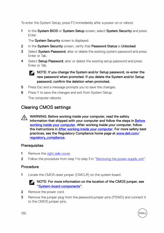
To enter the System Setup, press F2 immediately after a power-on or reboot.
1 In the System BIOS or System Setup screen, select System Security and press Enter.
The System Security screen is displayed.
2 In the System Security screen, verify that Password Status is Unlocked.
3 Select System Password, alter or delete the existing system password and press Enter or Tab.
4 Select Setup Password, alter or delete the existing setup password and press Enter or Tab.
NOTE: If you change the System and/or Setup password, re-enter the new password when promoted. If you delete the System and/or Setup password, confirm the deletion when promoted.
5 Press Esc and a message prompts you to save the changes.
6 Press Y to save the changes and exit from System Setup.
The computer reboots.
Clearing CMOS settings
WARNING: Before working inside your computer, read the safety information that shipped with your computer and follow the steps in Before working inside your computer. After working inside your computer, follow the instructions in After working inside your computer. For more safety best practices, see the Regulatory Compliance home page at www.dell.com/regulatory_compliance.
Prerequisites
1 Remove the right side-cover.
2 Follow the procedure from step 1 to step 3 in “Removing the power-supply unit”.
Procedure
1 Locate the CMOS reset jumper (CMCLR) on the system board.
NOTE: For more information on the location of the CMOS jumper, see “System-board components”.
2 Remove the power cord.
3 Remove the jumper plug from the password jumper-pins (PSWD) and connect it to the CMOS jumper-pins.
130
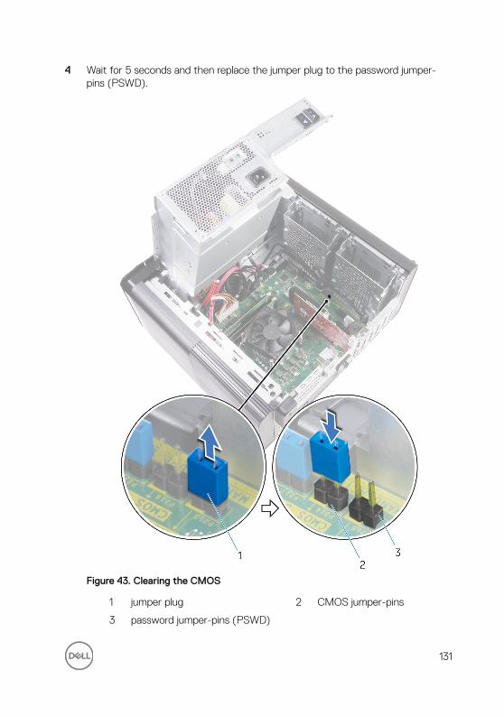
4 Wait for 5 seconds and then replace the jumper plug to the password jumper-pins (PSWD).
Figure 43. Clearing the CMOS
1 jumper plug 2 CMOS jumper-pins
3 password jumper-pins (PSWD)
131
Post-requisites
1 Replace the right side-cover.
2 Follow the procedure from step 9 to step 10 in “Replacing the power-supply unit”.
Clearing forgotten passwords
WARNING: Before working inside your computer, read the safety information that shipped with your computer and follow the steps in Before working inside your computer. After working inside your computer, follow the instructions in After working inside your computer. For more safety best practices, see the Regulatory Compliance home page at www.dell.com/regulatory_compliance.
Prerequisites
1 Remove the right side-cover.
2 Follow the procedure from step 1 to step 3 in “Removing the power-supply unit”.
Procedure
1 Locate the password reset jumper (PSWD) on the system board.
NOTE: For more information on the location of the password reset jumper, see “System-board components”.
132
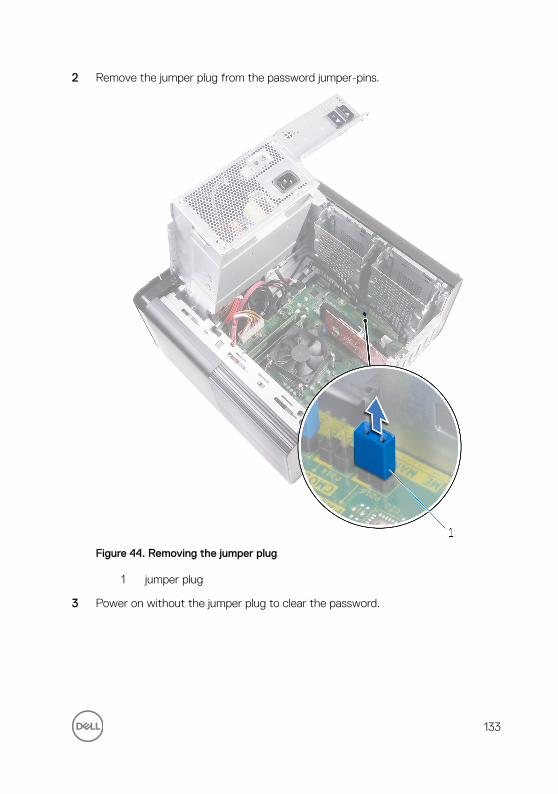
2 Remove the jumper plug from the password jumper-pins.
Figure 44. Removing the jumper plug
1 jumper plug
3 Power on without the jumper plug to clear the password.
133

4 Wait until the desktop is loaded and then shut down the system and replace the jumper plug in its original location.
Figure 45. Clearing the password
1 jumper plug
Post-requisites
1 Replace the right side-cover.
134

2 Follow the procedure from step 9 to step 10 in “Replacing the power-supply unit”.
135

Troubleshooting
Flashing the BIOS
You may need to flash (update) the BIOS when an update is available or when you replace the system board.
Follow these steps to flash the BIOS:
1 Turn on your computer.
2 Go to www.dell.com/support.
3 Click Product support, enter the Service Tag of your computer, and then click Submit.
NOTE: If you do not have the Service Tag, use the auto-detect feature or manually browse for your computer model.
4 Click Drivers & downloads → Find it myself.
5 Select the operating system installed on your computer.
6 Scroll down the page and expand BIOS.
7 Click Download to download the latest version of the BIOS for your computer.
8 After the download is complete, navigate to the folder where you saved the BIOS update file.
9 Double-click the BIOS update file icon and follow the instructions on the screen.
Flashing BIOS (USB key)
1 Follow the procedure from step 1 to step 7 in "Flashing the BIOS" to download the latest BIOS setup program file.
2 Create a bootable USB drive. For more information see the knowledge base article SLN143196 at www.dell.com/support.
3 Copy the BIOS setup program file to the bootable USB drive.
4 Connect the bootable USB drive to the computer that needs the BIOS update.
5 Restart the computer and press F12 when the Dell logo is displayed on the screen.
6 Boot to the USB drive from the One Time Boot Menu.
7 Type the BIOS setup program filename and press Enter.
136
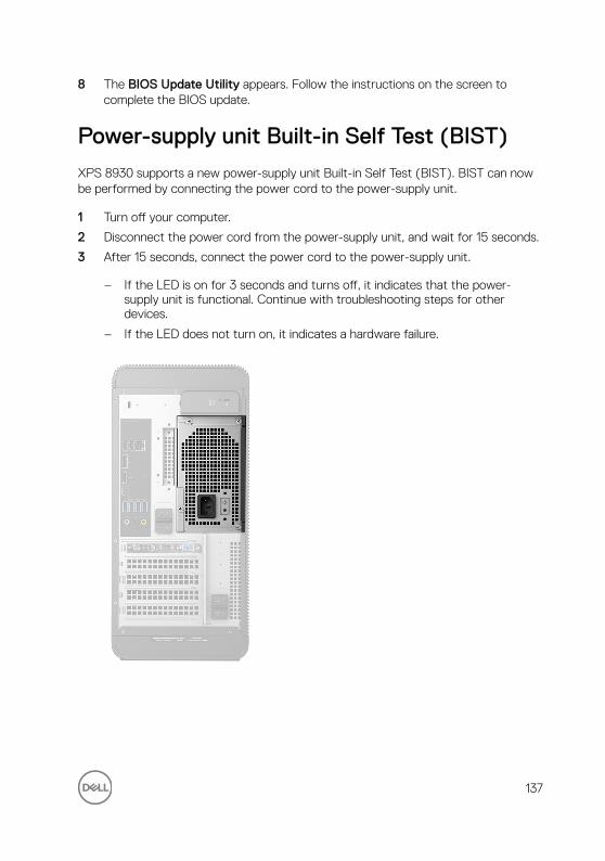
8 The BIOS Update Utility appears. Follow the instructions on the screen to complete the BIOS update.
Power-supply unit Built-in Self Test (BIST)
XPS 8930 supports a new power-supply unit Built-in Self Test (BIST). BIST can now be performed by connecting the power cord to the power-supply unit.
1 Turn off your computer.
2 Disconnect the power cord from the power-supply unit, and wait for 15 seconds.
3 After 15 seconds, connect the power cord to the power-supply unit.
– If the LED is on for 3 seconds and turns off, it indicates that the power-supply unit is functional. Continue with troubleshooting steps for other devices.
– If the LED does not turn on, it indicates a hardware failure.
137

Steps to confirm that power-supply unit is defective
1 Disconnect the power cord from the power-supply unit.
CAUTION: Ensure that you take adequate safety precautions before accessing the components on your computer. See the removing and replacing instructions in the service manual for procedure to access the power-supply unit and its cables.
2 Disconnect the power-supply unit cables from the system board.
3 Connect the power cord to the power-supply unit.
– If the LED is on for 3 seconds and turns off, it indicates that the power-supply unit is functional. Continue with troubleshooting steps for other devices.
– If the LED does not turn on, it indicates a power-supply unit failure. Replace the power-supply unit only.
Enhanced Pre-Boot System Assessment (ePSA) diagnostics
CAUTION: Use the ePSA diagnostics to test only your computer. Using this program with other computers may cause invalid results or error messages.
The ePSA diagnostics (also known as system diagnostics) performs a complete check of your hardware. The ePSA is embedded with the BIOS and is launched by the BIOS internally. The embedded system diagnostics provides a set of options for particular devices or device groups allowing you to:
• Run tests automatically or in an interactive mode
• Repeat tests
• Display or save test results
• Run thorough tests to introduce additional test options to provide extra information about the failed device(s)
• View status messages that inform you if tests are completed successfully
• View error messages that inform you of problems encountered during testing
NOTE: Some tests for specific devices require user interaction. Always ensure that you are present at the computer terminal when the diagnostic tests are performed.
138

For more information, see Dell EPSA Diagnostic 3.0.
Running the ePSA diagnostics
1 Power-on the computer.
2 As the computer boots, press the F12 key as the Dell logo appears.
3 On the boot menu screen, select the Diagnostics option.
4 Click the arrow key at the bottom left corner.
Diagnostics front page is displayed.
5 Press the arrow in the lower-right corner to go to the page listing.
The items detected are listed.
6 To run a diagnostic test on a specific device, press Esc and click Yes to stop the diagnostic test.
7 Select the device from the left pane and click Run Tests.
8 If there are any issues, error codes are displayed.
Note the error code and validation number and contact Dell.
Diagnostics
The computer POST (Power On Self Test) ensures that it meets the basic computer requirements and the hardware is working appropriately before the boot process begins. If the computer passes the POST, the computer continues to start in a normal mode. However, if the computer fails the POST, the computer emits a series of LED codes during the start-up. The system LED is integrated on the Power button.
The following table shows different light patterns and what they indicate.Table 9. Diagnostics
Number of LED flashes Problem description
1 System board: BIOS and ROM failure
2 No memory or RAM detected
3 System board or chipset error
4 Memory or RAM failure
5 CMOS battery failure
6 Video card or chip failure
139

Number of LED flashes Problem description
7 CPU failure
3,6 Recovery image not found
3,7 Recovery image found but invalid
Wi-Fi power cycle
If your computer is unable to access the internet due to Wi-Fi connectivity issues a Wi-Fi power cycle procedure may be performed. The following procedure provides the instructions on how to conduct a Wi-Fi power cycle:
1 Turn off your computer.
2 Turn off the modem.
3 Turn off the wireless router.
4 Wait for 30 seconds.
5 Turn on the wireless router.
6 Turn on the modem.
7 Turn on your computer.
140
Getting help and contacting Dell
Self-help resources
You can get information and help on Dell products and services using these self-help resources:Table 10. Self-help resources
Information about Dell products and services
www.dell.com
Dell Help & Support app
Accessing help In Windows search, type Help and Support, and press Enter.
Online help for operating system www.dell.com/support/windows
www.dell.com/support/linux
Troubleshooting information, user manuals, setup instructions, product specifications, technical help blogs, drivers, software updates, and so on.
www.dell.com/support
Dell knowledge base articles for a variety of computer concerns.
1 Go to www.dell.com/support.
2 Type the subject or keyword in the Search box.
3 Click Search to retrieve the related articles.
Learn and know the following information about your product:
• Product specifications• Operating system• Setting up and using your product• Data backup• Troubleshooting and diagnostics
See Me and My Dell at www.dell.com/support/manuals.
To locate the Me and My Dell relevant to your product, identify your product through one of the following:
• Select Detect Product.
141

• Factory and system restore
• BIOS information
• Locate your product through the drop-down menu under View Products.
• Enter the Service Tag number or Product ID in the search bar.
Contacting Dell
To contact Dell for sales, technical support, or customer service issues, see www.dell.com/contactdell.
NOTE: Availability varies by country and product, and some services may not be available in your country.
NOTE: If you do not have an active internet connection, you can find contact information on your purchase invoice, packing slip, bill, or Dell product catalog.
142