Xmq6117y3 Operation Manual _philippines 4 2014 Eb100072 81
144
- 1 - OPERATION MANUAL User’s Guide King-Long XMQ6117Y3 series tourist bus Xiamen King Long United Automotive Industry Co., Ltd.
Transcript of Xmq6117y3 Operation Manual _philippines 4 2014 Eb100072 81

7/21/2019 Xmq6117y3 Operation Manual _philippines 4 2014 Eb100072 81
http://slidepdf.com/reader/full/xmq6117y3-operation-manual-philippines-4-2014-eb100072-81 1/144
OPERATION MANUALUser’s Guide

7/21/2019 Xmq6117y3 Operation Manual _philippines 4 2014 Eb100072 81
http://slidepdf.com/reader/full/xmq6117y3-operation-manual-philippines-4-2014-eb100072-81 2/144
Foreword
2.FOREWORD
King-Long XMQ6117Y3 series touring bus keeps features of superior
economy, security and comfort. It has stable performance, strong power, luxury
interior trimming and high speed, which could meet applications of passenger
inter-city transportation, touring and business affairs, etc.
As for the specifications introduced in relate to information of the driving
and operation, service and maintenance of the XMQ6117Y3 series touring bus,
please read them carefully and make proper operation, maintenance and repair so
as to ensure it in good condition. Special hint: without authorization of Xiamen
King Long United Automotive Industry Co., Ltd, never modify the electrical
deployment of the whole vehicle, and should not lap the power supply line in
disorder. Improper usage and repair may have a strong impact on service
performance of the complete vehicle, and thus the manufacturer , Xiamen King
Long United Automotive Industry Co., Ltd. will not takes the responsibility for
the damages caused by them.
Any problem in service, please contact our special maintenance network or
after-sales department. We will ensure timely and complete maintenance as well
as original parts supply.
In order to satisfy all kinds of different demand of the consumers, we strive
to improve the quality of the product continuously to optimize our products. We
should not give any further notice for any modification of the product in advance .
The contents on the instruction book can only be used as reference. If there are

7/21/2019 Xmq6117y3 Operation Manual _philippines 4 2014 Eb100072 81
http://slidepdf.com/reader/full/xmq6117y3-operation-manual-philippines-4-2014-eb100072-81 3/144
Contents
Contents
Vehicle Picture--------------------------------------------------------------------------------------------------------1
Foreword---------------------------------------------------------------------------------------------------------------2
Contents
Contents----------------------------------------------------------------------------------------------------------------3
Main overall technical parameters
Technical parameters ------------------------------------------------------------------------------------------------7
Introduction to data plate-------------------------------------------------------------------------------------------8
Product quality assurance -------------------------------------------------------------------------------------------8
Technical document -------------------------------------------------------------------------------------------------8
Vehicle body structure-----------------------------------------------------------------------------------------------9
Schematic illustration of the driver zone-------------------------------------------------------------------------10
Operation Instruction
Instrument instruction---------------------------------------------------------------------------------------------I-1
Illustration of switch and indicator s----------------------------------------------------------------------------SI-1
Air conditioner control panel-----------------------------------------------------------------------------------P-A-1
Changing gears--------------------------------------------------------------------------------------------------O-G-1
Open or close the passenger door-----------------------------------------------------------------------------O-K-1
Adjustment of the driver's seat----------------------------------------------------------------------------------OI-1
Horn button---------------------------------------------------------------------------------------------------------OI-2
Adjustment of the steering wheel-------------------------------------------------------------------------------OI-3
Ignition switch----------------------------------------------------------------------------------------------------OI-4

7/21/2019 Xmq6117y3 Operation Manual _philippines 4 2014 Eb100072 81
http://slidepdf.com/reader/full/xmq6117y3-operation-manual-philippines-4-2014-eb100072-81 4/144
Contents
Switches----------------------------------------------------------------------------------------------------------O-C-5
Central Electricity Distributor s-------------------------------------------------------------------------------O-E-1
Vehicle traveling data recorder--------------------------------------------------------------------------------O-E-3
Switch control box----------------------------------------------------------------------------------------------O-E-4
The fan angle transmission mechanism---------------------------------------------------------------------- O-E-5
Vehicle starting and driving
Check oil level of the engine--------------------------------------------------------------------------------------S-1
Check level of the coolant-----------------------------------------------------------------------------------------S-2
Check fuel pre-filter with water separator-----------------------------------------------------------------------S-3
Check fuel level-----------------------------------------------------------------------------------------------------S-4
Check vehicle lighting, intermittent lights and brake lights---------------------------------------------------S-5
Drain water in air tank---------------------------------------------------------------------------------------------S-8
Check engine oil pressure------------------------------------------------------------------------------------------S-9
Check Pneumatic pressure---------------------------------------------------------------------------------------S-10
Check Tachometer working order-------------------------------------------------------------------------------S-11
Steering wheel play-----------------------------------------------------------------------------------------------S-12
Check tire for abrasion and pressure and tire nut for fixture------------------------------------------------S-13
Air cleaner----------------------------------------------------------------------------------------------------------S-14
General leakages (water, oil, fluids and fuel) -----------------------------------------------------------------S-15
Fastening and state of seat belts---------------------------------------------------------------------------------S-16
Check emergency devices and driver’s tools (fire extinguisher) -------------------------------------------S-17
Windshield wipers and conditions of wiper blades and arms-----------------------------------------------S-18
El i l i i S 19
7/21/2019 Xmq6117y3 Operation Manual _philippines 4 2014 Eb100072 81
http://slidepdf.com/reader/full/xmq6117y3-operation-manual-philippines-4-2014-eb100072-81 5/144
Contents
Engine shut down-------------------------------------------------------------------------------------------------S-26
Engine start up and shut down in the engine compartment--------------------------------------------------S-27
Starting the vehicle------------------------------------------------------------------------------------------------S-28
Parking the vehicle------------------------------------------------------------------------------------------------S-29
Vehicle maintenance and service
General knowledge------------------------------------------------------------------------------------------------M-1
Maintenance of engine and chassis subassembly--------------------------------------------------------------M-1
Body maintenance ------------------------------------------------------------------------------------------------M-1
ABS system maintenance and service --------------------------------------------------------------------------M-1
Electrical system maintenance and notices --------------------------------------------------------------------M-2
Tire transposition--------------------------------------------------------------------------------------------------M-2
Adjustment of the clutch pedal freeplay------------------------------------------------------------------------M-3
Adjustment of the brake pedal freeplay-------------------------------------------------------------------------M-3
Bus cleaning--------------------------------------------------------------------------------------------------------M-3
Cleaning air filter --------------------------------------------------------------------------------------------------M-4
Cleaning outside of radiator -------------------------------------------------------------------------------------M-5
Coolant specification ---------------------------------------------------------------------------------------------M-5
Oil specification recommendation of the fuel and the lubricant---------------------------------------------M-6
Breaking-in of a new vehicle-------------------------------------------------------------------------------------M-9
Daily or Refueling Maintenance Operation-------------------------------------------------------------------M-11
Maintenance first 2500km --------------------------------------------------------------------------------------M-12
Maintenance per 5000km---------------------------------------------------------------------------------------M-14
Maintenance per 10000km--------------------------------------------------------------------------------------M-17
7/21/2019 Xmq6117y3 Operation Manual _philippines 4 2014 Eb100072 81
http://slidepdf.com/reader/full/xmq6117y3-operation-manual-philippines-4-2014-eb100072-81 6/144
Contents
Clutch---------------------------------------------------------------------------------------------------------------- C-6
Propeller shaft------------------------------------------------------------------------------------------------------C-8
Transmission--------------------------------------------------------------------------------------------------------C-9
Rear axle-----------------------------------------------------------------------------------------------------------C-10
Front axle and steering system----------------------------------------------------------------------------------C-11
Braking system----------------------------------------------------------------------------------------------------C-14
Electrical equipment and the starting system ---------------------------------------------------------------C-16
Air conditioner system-------------------------------------------------------------------------------------------C-18
Appendix
Driver's tool table ---------------------------------------------------------------------------------------------- A-1
Tightening moment of the bolts and the nuts in major position--------------------------------------------A-2
Table of lubricant, oil & power steering oil--------------------------------------------------------------------A-3
JKH2028 schematic diagram-------------------------------------------------------------------------------------A-4
Air braking schematic diagram (with air suspension) ------------------------------------------------------- A-5
Electrical elementary diagram of vehicle --------------------------------------------------------------------A-6

7/21/2019 Xmq6117y3 Operation Manual _philippines 4 2014 Eb100072 81
http://slidepdf.com/reader/full/xmq6117y3-operation-manual-philippines-4-2014-eb100072-81 7/144
Technical parameter and complete vehicle description
Technical parameters of the complete vehicle EB100072-81)6117Y3
Product model 6117Y3
Engine model YC6G270 30
Engine type In-line six-cylinder water-cooling electric-injection diesel
engine
Cylinder diameter × stroke (mm) 112×132
Displacement (ml) 7800
Compression ratio 17.3:1
Rated capacity / rotation speed (kw/rpm) 199/2200
Max. torque / rotation speed (N·m/rpm) 1080/1400-1600
Di m en s i on s
Overall length (mm) 10600
Overall width (mm) 2480
Overall height(mm) 3580
Wheelbase (mm) 5250
Wheel trackfront (mm) 2020
rear (mm) 1860
Minimum lift-off clearance(mm) 260
Approach angle/ departure angle (°) 10/9
Front overhang / rear overhang (mm) 2200/3150
Rated passenger (driver included) (person) 49(double door 46)
M a s s p a r a m e t e r
Kerb weight(kg) 11000
Max. gross mass (kg) 15000
No loadFront axle (kg) 3500
Rear axle (kg) 7500
Full loadFront axle (kg) 5500
Rear axle (kg) 9500
P erf ormance
paramet er
Max. speed (km/h) 115Fuel consumption (L) --
Maximum gradeability
(%)
≥20
Min. turning diameter (m) ≤24

7/21/2019 Xmq6117y3 Operation Manual _philippines 4 2014 Eb100072 81
http://slidepdf.com/reader/full/xmq6117y3-operation-manual-philippines-4-2014-eb100072-81 8/144
Technical parameter and complete vehicle description
Introduction to data plate
Bus data plate
The bus data plate may be affixed to either the
upside of the front passenger door frame or to the
side of the front passenger door step(the position
may vary with vehicle model). There are many
parameters on the plate, such as vehicle model,
gross mass, vehicle serial number, vehicle capacity,
VIN (short for vehicle identification number),
chassis serial number, engine serial number, engine
model, rated power, production data and etc..
chassis serial number, engine serial number, engine
model, rated power, production data and etc..
Chassis data plate
The chassis data plate is on right (or left) lateral surface
of the front wheel position of the main sill with vehicle
identification number (VIN)on the frame.
Engine data plate
The engine data plate is on top surface or salient
top position of the engine whose position may be
various according to different engine manufacturing
plant

7/21/2019 Xmq6117y3 Operation Manual _philippines 4 2014 Eb100072 81
http://slidepdf.com/reader/full/xmq6117y3-operation-manual-philippines-4-2014-eb100072-81 9/144
Technical parameter and complete vehicle description
regulations in the instruction book. Please refer to “workshop manual” for product quality assurance
and abide by related specification.
Technical document
The instruction book is used combined to the following specification:
Engine operation instruction or service manual
Transmission operation manual
CAN BUS Instrument system instruction book
ABS anti-braking system instruction book
Air conditioner instruction book
Heater instruction book
Monitor instruction book
Note: the instruction book should be modified according to specific configuration of vehicle.

7/21/2019 Xmq6117y3 Operation Manual _philippines 4 2014 Eb100072 81
http://slidepdf.com/reader/full/xmq6117y3-operation-manual-philippines-4-2014-eb100072-81 10/144
Technical parameter and complete vehicle description
Body Structure
1. Structural styleSemi-integral body structure
2. Structure
The bodywork structure adopts closed girder construction of five major assembly parts, which are
combined welded by rectangle steel pipes with advantages of strong structural stiffness, torsionresistance and bending resistance as well as relatively simple craftwork. Main components of chassis,
skeleton have been performed as electrophoresis , anticorrosion treatment to ensure steady adhesion of
coating and strong capacity of antirust and corrosion-proof.
3. Interior trim
The interior adopts flexible design and the floor adopts steel plate/wood block composite construction,and covered with anti-slip and antifriction leather with favorable sound insulation value.
4. Windows
The front windshield is the hyperboloid triplex glass fixed by the gluing; the rear windshields are the
hardened glass fixed by the gluing; the side windows are close cycle window which are made of
hardened glass. The driver’s window is fixed with lifting window.
5. Baggage compartmentThe baggage compartment adopts transverse run-through design, and they are all made of aluminum.
6. SeatDriver’s seat: J05 type adjustable seat with high backrest and three-point belt.
Passenger seats: H type, high backrest, adjustable, parts of seats are fully equipped with two points
safety belts.
7. Interior accessory device
The vehicle is equipped with electronic clock, sunshade, safety hammer, emergency escaping window,
curtain and F type luggage rack, guiding seat , MP3 player, reading lamp.etc.,
8. Air-conditioning system
Cooling system: KINGLONG top mounted dependent air-conditioning system
Heating system: without installing.
9. Door
The door adopts the full aluminum remote control , out-swing pneumatic doors.The out-swing door adopts the advanced electrically aerodynamic theory design, with the motion of
opening and closing placidly、agile、safe、lock credible and anti-clamp function.

7/21/2019 Xmq6117y3 Operation Manual _philippines 4 2014 Eb100072 81
http://slidepdf.com/reader/full/xmq6117y3-operation-manual-philippines-4-2014-eb100072-81 11/144
Technical parameter and complete vehicle description
c. In order to avoid impact, make sure that the door is completed closed or opened, before you make the
next door switch operation.
Note: Deployment on the vehicle may be different with the above description because of differentdeploying requirement of the clients.
Schematic illustration of the driver zone
1 Parking brake hand lever
2 A/C t l l
8 Combination instrument
9 St i h l
1
2
4
5
3
6
7 8 9 10 11 12
13

7/21/2019 Xmq6117y3 Operation Manual _philippines 4 2014 Eb100072 81
http://slidepdf.com/reader/full/xmq6117y3-operation-manual-philippines-4-2014-eb100072-81 12/144
Operation Instruction
Instruction of instrument (VITI EDITION)
Display On LCD (VITI EDITION)
(1) Indicate the information of the clock
Engine speed Signal displayerVehicle speed
Recharge voltage
AT position indicator
S1 S2 S3 S4
Air pressure I
Fuel level
Digital display screen
Coolant temp.
Air pressure II
Oil pressure

7/21/2019 Xmq6117y3 Operation Manual _philippines 4 2014 Eb100072 81
http://slidepdf.com/reader/full/xmq6117y3-operation-manual-philippines-4-2014-eb100072-81 13/144
Operation Instruction
When warning、operation and state occur, the LCD will indicate current warning information
automatically, One screen only can indicate three warning icon at the same time, if there are more than
three warning information, please press the key to turn over screen. The icon indicated at the time
zone delegating the hint of warning、operation and state.
(7) Prompt hint, for the vehicle with installment plan, the manufacturer may choose prompt hint.
the recorder will begin to send the prompt hint information to the time zone 7 days before the prompt,
the LCD instrument indicator indicates “the remainder of the prompt: X day”.
The format as shown below:
when the prompt matured ,all the pointer return to zero, at the same time the LCD indicated: “the
prompt has matured” The format as shown below:
(8)When the circuit is on “on” position ,the LCD will indicate default format as below:
Keystroke
there are four operational keys(from left to right)on the instrument : S1 S2 S3 S4(see the outline
7/21/2019 Xmq6117y3 Operation Manual _philippines 4 2014 Eb100072 81
http://slidepdf.com/reader/full/xmq6117y3-operation-manual-philippines-4-2014-eb100072-81 14/144
Operation Instruction
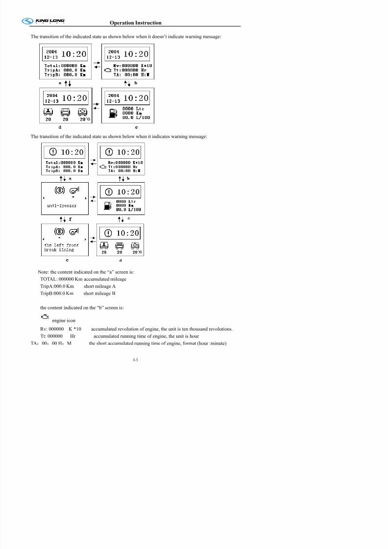
The transition of the indicated state as shown below when it doesn’t indicate warning message:
The transition of the indicated state as shown below when it indicates warning message:
Note: the content indicated on the “a” screen is:

7/21/2019 Xmq6117y3 Operation Manual _philippines 4 2014 Eb100072 81
http://slidepdf.com/reader/full/xmq6117y3-operation-manual-philippines-4-2014-eb100072-81 15/144
Operation Instruction
the content indicated on the “c” screen is:
fuel icon
0000 Ltr the remainder fuel
* 0000 Km the mileage that the remainder fuel can supply to the vehicle to run.
* 00.0 L/100 Fuel consumption
( * this function is out of stock at the moment )
the content indicated on the “d” screen is:
interior temperature of the vehicle(-20 ~ +40℃)
outside temperature of the vehicle (-20 ~ +40℃)
compartment temperature (40 ~ 120℃)
“e” screen indicate warning message
“f” screen indicate warning messageunder the state of default screen ,press the key S2 for long time can clear the mileage A and the②
short accumulated running time of engine, press the key S3 for long time can clear the mileage B.
The indicated state as shown below:
During modify the clock, the key S2③ 、S3 have the plus and minus function.
when there are several warning indicated on the screen press the key S2 can move the④

7/21/2019 Xmq6117y3 Operation Manual _philippines 4 2014 Eb100072 81
http://slidepdf.com/reader/full/xmq6117y3-operation-manual-philippines-4-2014-eb100072-81 16/144
Operation Instruction
Illustration of the LCD and signal items (VITI & Mewyeah system)
Ico
indicate alarm(such as alarm for water temperature, alarm for oil pressure)、operation(such as
the left and right turning)and state(ABS operating Indicator ,Retarder operating Indicator ). The
icon signification is listed in the following sheet,The important signals are indicated directly by
lighting LED icon,and the other icons are indicated on the LCD.
IcoDisplay
position
Icon name Icon meaning
Signal item anti-lock ABS fault
LCD screen Anti side-slip ASR fault
LCD screen ECAS Air suspension fault
LCD screen cruise Cruise working indicate
LCD screen
Compartment
temperature
Engine Compartment temperature warning
LCD screen Interior temperature Interior temperature indicate
LCD screen Outside temperature outside temperature indicate
LCD screen Back-up lamp Back-up lamp indicate
Signal item Master lighting switch Master lighting switch
Signal item Waiting for engine start
Engine fault warningSignal item Engine maintenance
Signal item Engine stop
LCD screen Number one door Front door open indicate

7/21/2019 Xmq6117y3 Operation Manual _philippines 4 2014 Eb100072 81
http://slidepdf.com/reader/full/xmq6117y3-operation-manual-philippines-4-2014-eb100072-81 17/144
Operation Instruction
IcoDisplay
positionIcon name Icon meaning
red LCD screen Electricity scarcity Generator doesn’t work
Signal item Preheating Engine Preheating indicate
LCD screen Air filter Air filter warning
Signal item Charging indicator Battery Charging indicate
STOP Signal item Stop the vehicle at once
LCD screen Anti-freezer Anti-freezer working
LCD screen Desiccator Desiccator working
LCD screen
Engine compartment
flap
Engine compartment flap is open
Signal itemRear fog lamp light Rear fog lamp light
Signal itemFront fog lamp light Front fog lamp light
LCD screenOil filter Oil filter is clogged indicate
Signal itemOil pressure Oil pressure too low indicate
LCD screen Centralized lubrication Centralized lubrication is applied
Signal item Dipped headlight Dipped headlight is applied
Signal item High beam High beam is applied indicate
Signal item Retardar Retardar is applied indicate
Signal item The quantity of fuel Refuel indicate
LCD screen Fuel filter Fuel filter seeper warning

7/21/2019 Xmq6117y3 Operation Manual _philippines 4 2014 Eb100072 81
http://slidepdf.com/reader/full/xmq6117y3-operation-manual-philippines-4-2014-eb100072-81 18/144
Operation Instruction
LCD screen Right compartment door Right compartment door open indicate
7/21/2019 Xmq6117y3 Operation Manual _philippines 4 2014 Eb100072 81
http://slidepdf.com/reader/full/xmq6117y3-operation-manual-philippines-4-2014-eb100072-81 19/144
Operation Instruction
IcoDisplay
positionIcon name Icon meaning
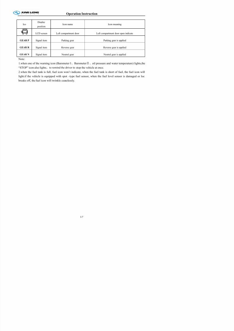
LCD screen Left compartment door Left compartment door open indicate
GEAR P Signal item Parking gear Parking gear is applied
GEAR R Signal item Reverse gear Reverse gear is applied
GEAR N Signal item Neutral gear Neutral gear is applied
Note:
1.when one of the warning icon (Barometer I、Barometer Ⅱ、oil pressure and water temperature) lights,the
“STOP” icon also lights,to remind the driver to stop the vehicle at once.
2.when the fuel tank is full, fuel icon won’t indicate, when the fuel tank is short of fuel, the fuel icon will
light.if the vehicle is equipped with spot –type fuel sensor, when the fuel level sensor is damaged or loc
breaks off, the fuel icon will twinkle ceaselessly.

7/21/2019 Xmq6117y3 Operation Manual _philippines 4 2014 Eb100072 81
http://slidepdf.com/reader/full/xmq6117y3-operation-manual-philippines-4-2014-eb100072-81 20/144
Operation Instruction
Illustration of switch and indicator
Number of switches and indicators and position may vary with vehicle model, please consult the flowing
sheet and use correctly according to actual condition of vehicle.
Switch Name Color Function Notes
Retarder Green
Pressed on top: retarder is turned ON
Pressed on bottom: retarder is turned OFF
Retarder turn off
switch
Pressed on top: retarder is turned OFF
Pressed on bottom: retarder is turned ON
Daylight lamp Green Pressed on top: interior lighting ON,
Pressed on bottom: interior lighting OFF
Hazard lamp Red when the vehicle have a screw loose, switch
it on, the whole vehicle lamps light
Luggage
compartment lamp Green
Pressed on top: lamp lights ,
Pressed on bottom: lamp goes out
Compulsory
radiator Green
Pressed on top: radiator working ;
Pressed on bottom: to turn it off
only use this button
when vehicle is stopping
Ventilator Green Pressed on top: ventilator is active,
Pressed on bottom: ventilator is turned off
Front fog lamp Green Pressed on top: front fog lamps ON,
Pressed on bottom: front fog lamps OFF
Rear fog lamp Yellow Pressed on top: rear fog lamps ON,
P d b tt f l OFF

7/21/2019 Xmq6117y3 Operation Manual _philippines 4 2014 Eb100072 81
http://slidepdf.com/reader/full/xmq6117y3-operation-manual-philippines-4-2014-eb100072-81 21/144
Operation Instruction
Switch Name Color Function Notes
horn GreenPressed on top: air horn is active, Pressed on
bottom: electric horn is active
Engine idle GreenPressed on top: engine idle speed raise,
Pressed on bottom: engine idle speed lower
adjust engine
speed
Front passenger door Green
press button once to open front passenger
door;
press button again to close
Rear passenger door Green press button once to open passenger door;
press button again to close
Electric curtain Green Pressed on top: to raise curtain;
Pressed on bottom: to lower curtain
TV green Pressed on top: TV is turned ON,
Pressed on bottom: TV is turned OFF
Reversal monitor Green
Pressed on top: reversal monitor turned ON,
Pressed on bottom: reversal monitories
turned OFF
Rearview mirror
defrost(preheating) Yellow
Pressed on top: preheating ON,
Pressed on bottom: preheating OFF
Diagnose Green press this button to make a diagnosis ofengine, when engine indicate trouble
Disinfect Green
Pressed on top: disinfection turned ON,
Pressed on bottom: disinfection
t d OFF

7/21/2019 Xmq6117y3 Operation Manual _philippines 4 2014 Eb100072 81
http://slidepdf.com/reader/full/xmq6117y3-operation-manual-philippines-4-2014-eb100072-81 22/144
Operation Instruction
Switch Name Color Function Notes
Exterior guidepost Red Pressed on top: turn on guidepost lamp;
Pressed on bottom: turn off guidepost lamp
Assistant brake Yellow Pressed on top: turn on assistant brake;
Pressed on bottom: to turn it off
only switch on when
vehicle need park
Vehicle level reset Green Pressed on top: vehicle level reset
Emergency power Red
Pressed on top: emergency power turned ON
Pressed on bottom: emergency power is
turned OFF
Toilet power switch Green
Pressed on top: Toilet power is turned ON,
Pressed on bottom: Toilet power is turned
OFF
Heater switch Red Pressed on top: to turn on heater ;
Pressed on bottom: to turn it off
TV overturn switch Green
Pressed on top: expand the TV,
Pressed on bottom: collapse the TV
Fresh air switch Green
Pressed on top: turn on the changing fresh
air function;
Pressed on bottom: turn off the changing
fresh air function.
Electric driver windowswitch
Green Pressed on top: the glass getting up;Pressed on bottom: the glass getting down.
Electric driver window
defrosting switchYellow
Pressed on top: turn on defrosting function;
Pressed on bottom: turn off defrosting
function

7/21/2019 Xmq6117y3 Operation Manual _philippines 4 2014 Eb100072 81
http://slidepdf.com/reader/full/xmq6117y3-operation-manual-philippines-4-2014-eb100072-81 23/144
Operation Instruction
Switch Name Color Function Notes
Right side bin gate Green
Pressed on top: open the right side bin gate;
Pressed on bottom: close the right side bin
gate.
Powerful/abstemious
transfer switch
Pressed on top: turn on powerful function;
Pressed on bottom: turn off abstemious
function.
Electric sun blind GreenPressed on top: the sun blind getting down;
Pressed on bottom: the sun blind getting up.
Driver seat lamp switch Green
Pressed on top: turn on the driver seat lamp;
Pressed on bottom: turn off the driver seat
lamp.
Kneeling switch Green
Pressed on top: turn on kneeling function;
Pressed on bottom: turn off kneeling
function.
Coin box switch GreenPressed on top: open the coin box;
Pressed on bottom: turn off the coin box.
Turning lamp switch Green
Pressed on top: turn on the turning lamps;
Pressed on bottom: turn off the turninglamps.
ACU unlock switch GreenPressed on top: ACU unlock;
Pressed on bottom: ACU lock.
For articulate
plate only
Inner guidepost switch Green
Pressed on top: turn on the inner guidepost;
Pressed on bottom: turn off the inner
guidepost.

7/21/2019 Xmq6117y3 Operation Manual _philippines 4 2014 Eb100072 81
http://slidepdf.com/reader/full/xmq6117y3-operation-manual-philippines-4-2014-eb100072-81 24/144
Operation Instruction
Indicator lamp Color Function
Red passenger door open indicating
Red natural gas leakage indicating
Red front passenger door open indicate
Red rear passenger door open indicating
Red exit has been open indicating
hollow plate
Yellow ECAS alarm indicating
Red ECAS fault indicating
Red gearbox fault warning indicating
Green retarder indicating
yellow Fuel filter seeper
Hollow plate
Yellow Maintain waiting
yellow Start
Red Stop
Yellow Alarm

7/21/2019 Xmq6117y3 Operation Manual _philippines 4 2014 Eb100072 81
http://slidepdf.com/reader/full/xmq6117y3-operation-manual-philippines-4-2014-eb100072-81 25/144
Operation Instruction
Indicator lamp Color Function
Red Transmission oil temperature too high
Red Transmission fault
White Start-up waiting
Yellow Over emission
Yellow Kneeling lamp
Green Normal height

7/21/2019 Xmq6117y3 Operation Manual _philippines 4 2014 Eb100072 81
http://slidepdf.com/reader/full/xmq6117y3-operation-manual-philippines-4-2014-eb100072-81 26/144
Operation Instruction
Air conditioner control panel(SK-17-1)
Air conditioner(KL-XB2)
Control panel operation:
1) How to use the air conditioner
Start the engine⑴
turn ON the cooling switch⑵ , push
set the suitable temperature⑶ the setting temperature will be held automatically
Indicator light introduction:
low air speed
midterm air speed
high air speed
Cooling
Setting Temp
Pressure alarm indicator
Fresh air
Select key introduction:
Power key
Select ensure key
Air speed select key
Fresh air select key
Up key
Down key
Temperature display
7/21/2019 Xmq6117y3 Operation Manual _philippines 4 2014 Eb100072 81
http://slidepdf.com/reader/full/xmq6117y3-operation-manual-philippines-4-2014-eb100072-81 27/144
Operation Instruction
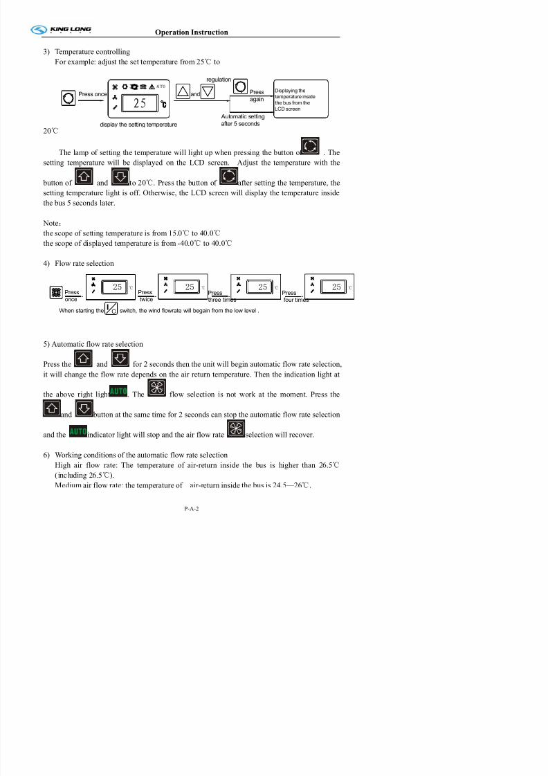
3) Temperature controlling
For example: adjust the set temperature from 25 to℃
20℃
AUTO
25Press once and
regulation
Press
again
display the setting temperature
Automatic setting
after 5 seconds
Displaying the
temperature inside
the bus from the
LCD screen
The lamp of setting the temperature will light up when pressing the button of . The
setting temperature will be displayed on the LCD screen. Adjust the temperature with the
button of and to 20 . Press the button of℃ after setting the temperature, the
setting temperature light is off. Otherwise, the LCD screen will display the temperature inside
the bus 5 seconds later.
Note:
the scope of setting temperature is from 15.0 to 40.0℃ ℃
the scope of displayed temperature is from -40.0 to 40.0℃ ℃
4) Flow rate selection
℃2525 ℃
When starting the switch, the wind flowrate will begain from the low level .
→Press
four times→
Press
three times→
Press
twice
Press
once→
℃25
O
25 ℃
5) Automatic flow rate selection
Press the and for 2 seconds then the unit will begin automatic flow rate selection,
it will change the flow rate depends on the air return temperature. Then the indication light at

7/21/2019 Xmq6117y3 Operation Manual _philippines 4 2014 Eb100072 81
http://slidepdf.com/reader/full/xmq6117y3-operation-manual-philippines-4-2014-eb100072-81 28/144
Operation Instruction
Low air flow rate: the temperature of air-return inside the bus is lower than 24℃
(including 24 ).℃
When switching air flow rate by different temperature, the switching confirm time is 30seconds.
7) Temperature control method
Using ON/OFF mode:the temperature controlling precision (DIF)is 2℃,(FIX
SETTING)
For example: the temperature controlling precision(DIF)is 2℃,The setting temperature
is 25 .℃
When the bus inside temperature is 30 :℃
The cooling system will be stop (OFF) when the temperature reaching 25 .℃
The cooling system will be start (ON) for cooling (COOLING) when the temperature is
over 27 . The cooling℃ delay time is 10 seconds when it’s at the first starting,after this the
interval time is 30 seconds.
Temperature
cyc le2° C
(- C)
Setting temperature25°C
25 C
OFF cooling mode
27 C
(+ C)on cooling mode
8) Strong cooling
This function of maintenance is used in the season which the air conditioner does not use(over
2 insi℃ de of bus). The goal is provide the lubricant to the shaft sealing ring by the pressure of
the working compressor. Normally it works 10 minutes and once or twice every month.
9) Operation of strong cooling

7/21/2019 Xmq6117y3 Operation Manual _philippines 4 2014 Eb100072 81
http://slidepdf.com/reader/full/xmq6117y3-operation-manual-philippines-4-2014-eb100072-81 29/144
Operation Instruction
11) The part below the LCD screen will flash when the defrosting function working.
D is p l a y t h e d e f ro s t in g te m p e r a t u r e
2 5 . 5 .
A U T O
Note:
The compressor (C⑴ OMP) and the condenser (COND) fan will stop working and
the evaporate (EVA) fan will run normally when the system defrosting.
The operation of the defrosting is automatically Controlled. the defrosting operation⑵
begins to work when the temperature of the sensor is(ON) at -1 and stops working (OFF)℃
at 8 .℃
12) Set the fresh air vent function
The LCD screen will display the Vent open (Vn) and the
setting time when the button pressed for 5 seconds. The button pressed again to show
VF and the setting time. Adjust the setting time by pressing the button of and to
the setting time within 1—60min.(Generally the setting time is 10 minutes). Press the button
for the confirming of the time setting, or the system will confirm the setting time
automatically in 5 seconds. Adjust the setting time by the button and within
1—60min when the LCD screen display VF and the setting time.(Generally the setting time is
30 minutes) Press the button for the confirming of the time setting or the system will

7/21/2019 Xmq6117y3 Operation Manual _philippines 4 2014 Eb100072 81
http://slidepdf.com/reader/full/xmq6117y3-operation-manual-philippines-4-2014-eb100072-81 30/144
Operation Instruction
red line voltage of control panel. Press the ,it shows the voltage of air conditioner
generator(when the air conditioner is without generator, it only shows the red line voltage ofcontrol panel i.e. the voltage of vehicle generator.)If it isn't operation during this process, it will
show the air return temperature after 5 seconds.
14),check and cleanup time
Press the for 12 seconds, it shows the working time of air conditioner. During this
procss it isn’t operation. After 5 seconds, it shows the air return inlet temperature. When the air
conditioner is working, press the and for 2 seconds at the same time. It can be
cleanup the time as 0.
Note:
the working time of air conditioner ,it can be calculated the time as hours since the low flow
rate is beginning. That can be added up every working time of turn off the unit and control
panel power off . It also can check and clean up the working time at any alarm condition.

7/21/2019 Xmq6117y3 Operation Manual _philippines 4 2014 Eb100072 81
http://slidepdf.com/reader/full/xmq6117y3-operation-manual-philippines-4-2014-eb100072-81 31/144
Operation Instruction
Changing gears (Manual gearbox QJ SERIES)
Operation Instruction:
Transmission Features: compact construction, light weight, small volume, easy control and gear shifting,
reliable performance, and convenient maintenance; flexible variety, adapt to multiple vehicle
configuration, high interchangeability.
Proper transmission use and maintenance may substantially improve your vehicle performance, power,
economy, reliability and safety as well. So, please strictly follow the tips given below:
■
Always try to drive you vehicle at higher but adequate gear, ensuring the engine run under economymode;
■When accelerating your vehicle speed, you may “jump the gear” (jump off one gear), to use the engine
power to its maximum extent;
■Please shift to higher gear when driving down a slope, to use the engine brake.
■Give sufficient attention to the road traffic, drive your vehicle at neutral gear by using vehicle’s
inertia.
■If unnecessary, always try to avoid sudden braking or accelerating.
Gearshift Steps:
(1)Do not release the accelerator pedal, and press the clutch pedal to its ultimate bottom (always
properly adjust the driver’s seat position)
(2)Smoothly but precisely move the shift leave to the desired position, if feeling resistance, you may
gradually force to move the lever until the lever reaching its position (after about one second);
(3)Release the clutch pedal and press down the accelerator pedal until an adequate driving speed.
Important: Not releasing the accelerator pedal for gear shifting can not only give your better “feel” for
gear shifting, and also result in substantial fuel saving.
For shifting to rear gear, you MUST stop your vehicle first, and move the Shift lever smoothly to avoid
any possible damage to the coupling sleeve.
One more thing, the drive SHALL try to get himself/herself familiarized with the driving speed of each
gear, avoiding drive at unsuitable gear, so as to prevent the engine and power train from over speed oroverload.
Clutch Adjustment
A. During the gear shifting time, clutch shall be pressed down to its ultimate limit, if the clutch is not

7/21/2019 Xmq6117y3 Operation Manual _philippines 4 2014 Eb100072 81
http://slidepdf.com/reader/full/xmq6117y3-operation-manual-philippines-4-2014-eb100072-81 32/144
Operation Instruction
(3) Initial maintenance to your vehicle is IMPERATIVE
(4) DO warm up the engine after startup; NEVER drive your vehicle when the water temperature is
below the startup temp. and/or the air pressure below the standard pressure; (5) DO NOT always drive your vehicle at low gear but with accelerator pedal pressed to its limit , and
DO NOT shift the gear to neutral at wrong time;
(6) NEVER move the shift lever forcefully, such as sudden push or pull, or recklessly move the lever;
(7) The 1st gear and Reverse Gear of this model of transmission;
(8) NEVER sliding your vehicle at neutral gear when driving down a slop..
Lugging: Lugging means that the gear is at high gear, but the vehicle speed can not reach its
corresponding high speed. For example, when the vehicle runs up a slope or carries big load, under such
condition, large torque is needed by the vehicle, though, even you shift the gear to high gear position,
the power is increased, but the torque is not sufficient for such condition.
O ti I t ti

7/21/2019 Xmq6117y3 Operation Manual _philippines 4 2014 Eb100072 81
http://slidepdf.com/reader/full/xmq6117y3-operation-manual-philippines-4-2014-eb100072-81 33/144
Operation Instruction
Changing gears
Always shift in first gear in order to put the vehicle in movement, especially if the vehicle isloaded or on a slope.
Regularly look at the tachometer while driving the vehicle. Select the adequate shifts in the
gear box to maintain the engine running at the most economic rotation regime, whenever
possible. Jump gears whenever possible to ensure a more economic driving.
Shift gears normally, pressing the clutch pedal totally, without effecting double unclutching,
without accelerating whilst at dead point, and moving the gear lever to the chosen position with
a smooth firm movement, avoiding tentative shifts by alternating strokes.
On shifting down, ensure that the speed of the vehicle is compatible with the gear to be entered
in order not to submit the engine to rotations above the maximum admissible limit.
Shift in back gear only when the engine is in idle gear and the vehicle is totally stopped.
Operation Instr ction
7/21/2019 Xmq6117y3 Operation Manual _philippines 4 2014 Eb100072 81
http://slidepdf.com/reader/full/xmq6117y3-operation-manual-philippines-4-2014-eb100072-81 34/144
Operation Instruction
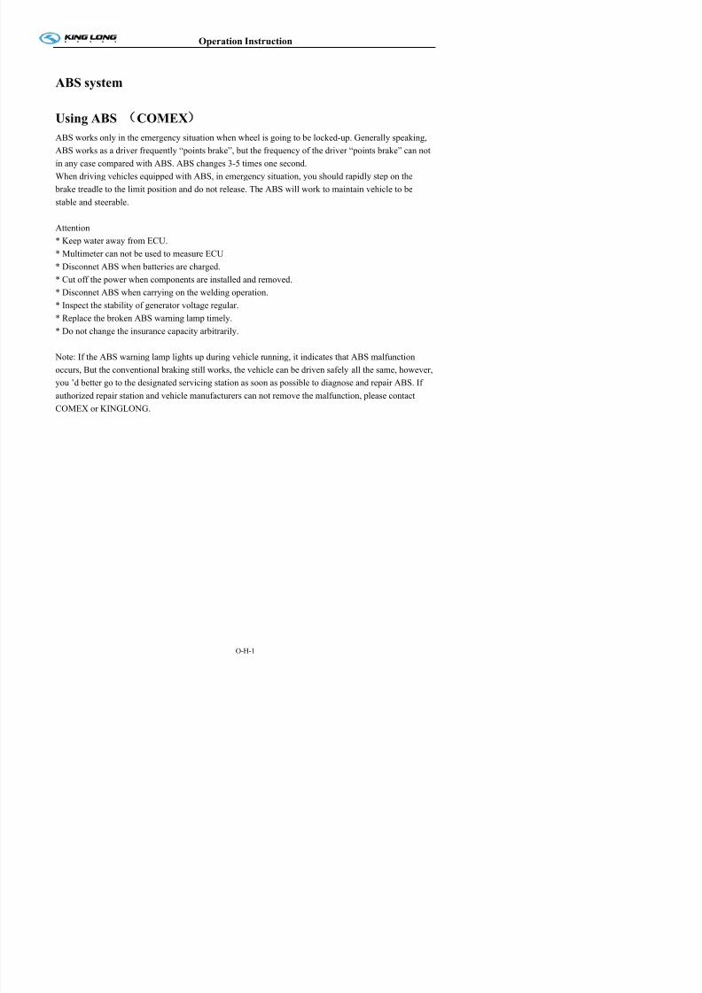
ABS system
Using ABS COMEX)
ABS works only in the emergency situation when wheel is going to be locked-up. Generally speaking,
ABS works as a driver frequently “points brake”, but the frequency of the driver “points brake” can not
in any case compared with ABS. ABS changes 3-5 times one second.
When driving vehicles equipped with ABS, in emergency situation, you should rapidly step on the brake treadle to the limit position and do not release. The ABS will work to maintain vehicle to be
stable and steerable.
Attention
* Keep water away from ECU.
* Multimeter can not be used to measure ECU
* Disconnet ABS when batteries are charged.* Cut off the power when components are installed and removed.
* Disconnet ABS when carrying on the welding operation.
* Inspect the stability of generator voltage regular.
* Replace the broken ABS warning lamp timely.
* Do not change the insurance capacity arbitrarily.
Note: If the ABS warning lamp lights up during vehicle running, it indicates that ABS malfunction
occurs, But the conventional braking still works, the vehicle can be driven safely all the same, however,
you ’d better go to the designated servicing station as soon as possible to diagnose and repair ABS. If
authorized repair station and vehicle manufacturers can not remove the malfunction, please contact
COMEX or KINGLONG.
Operation Instruction

7/21/2019 Xmq6117y3 Operation Manual _philippines 4 2014 Eb100072 81
http://slidepdf.com/reader/full/xmq6117y3-operation-manual-philippines-4-2014-eb100072-81 35/144
Operation Instruction
Open/close the passage door.
1. Before leaving the vehicle, press the button 1 ofthe door remote controller to close the door.
2. Use the key to lock the door. First insert key into
the hole 3 and clockwise rotate key about 90°,
then anticlockwise rotate handle 4, after that the
door would be locked.
3. If need open the passage door, insert key into thehole 3 and clockwise rotate it about 90°, then
clockwise rotate handle 4, follow press the button
2, after that the door would be opened.
Specification: For the king-long city bus, the
method of open and close the passage door is different
to above. Details please see the right drawing. The red
button is close button; the green button is open button.
This device usually located on the bin under the driver
seat compartment. If need open or close the front
1
3
4
21
2
Operation Instruction

7/21/2019 Xmq6117y3 Operation Manual _philippines 4 2014 Eb100072 81
http://slidepdf.com/reader/full/xmq6117y3-operation-manual-philippines-4-2014-eb100072-81 36/144
Operation Instruction
Appedix:
The following are all type of door lock and door remote controller of King-Long.
Lock1 Lock 2 Lock 3
Operation Instruction

7/21/2019 Xmq6117y3 Operation Manual _philippines 4 2014 Eb100072 81
http://slidepdf.com/reader/full/xmq6117y3-operation-manual-philippines-4-2014-eb100072-81 37/144
Operation Instruction
Door emergency switch
The model 1 door emergency switch is located on right
underside of the ingress.
The model 2 door emergency switch is located on right
upside of the door.The model 3 door emergency switch is located inside the
door pump cover which is on the top of the door.
Please rotate the switch and throw open the door in
emergency.
Special attention: The door emergency switch is only
used in the emergency mode. Please don't rotate the door
emergency switch in driving for fear of danger.
Door remote controller 1 Door remote controller 2
Model 1
Model 2
Operation Instruction

7/21/2019 Xmq6117y3 Operation Manual _philippines 4 2014 Eb100072 81
http://slidepdf.com/reader/full/xmq6117y3-operation-manual-philippines-4-2014-eb100072-81 38/144
p
Adjustment of the driver's seat
The driver's seat may be made proper adjustment for the
back and forth as well as the backrest angle according to
requirement of the driver.
Handle 1 and Handle 2: cushion angle adjustment
Handle 3: back and forth adjustment
Handle 4: adjustment of the driver’s weight
Left handle: backrest angle adjustment
Note: Number of handles varies with vehicle model
Attention!
The seat should not be adjusted during driving
to ensure driving safety.
1
2
3
4
Operation Instruction

7/21/2019 Xmq6117y3 Operation Manual _philippines 4 2014 Eb100072 81
http://slidepdf.com/reader/full/xmq6117y3-operation-manual-philippines-4-2014-eb100072-81 39/144
p
Horn button
It is on the steering wheel. The horn is hooting when pressing the button 1.
The type of steering wheel may vary with vehicle model.
Please use the horn only when strictly necessary to warn
other drivers and pedestrians.
Model 1
Model 2
1
1
Operation Instruction

7/21/2019 Xmq6117y3 Operation Manual _philippines 4 2014 Eb100072 81
http://slidepdf.com/reader/full/xmq6117y3-operation-manual-philippines-4-2014-eb100072-81 40/144
Adjustment of the steering wheel
Pull-up the loosening handle 1 or rotate the loosening button
2. Adjust the height and the inclination of the steering wheel
to the desired position. After adjusting, press the regulating
handle or button down to lock the steering column.
Note: Number of handles varies with vehicle model
Attention!
Adjust the steering wheel only when the vehicle is stopped
and the parking brake is on.
After adjusting, press the regulating handle or button down
in order to lock the steering column.
1
2
Operation Instruction

7/21/2019 Xmq6117y3 Operation Manual _philippines 4 2014 Eb100072 81
http://slidepdf.com/reader/full/xmq6117y3-operation-manual-philippines-4-2014-eb100072-81 41/144
Ignition switch
Position of the ignition key is shown in fig.1.
"K" KEY: for inserting and drawing out position of thestartup key
1."L" LOCK: Insert or remove the key in this position.
2."A" ACC: Power supply of the instrument is switched on
3."O" ON: Normal driving position
4."S" START: Initiating position of the engine, and the key
may rebound to the "ON" position automatically after the
startup.
Before starting the engine, turn the key to the “ACC”
position and then to the “ON” position. At this point, three
lights (red, yellow and green) on the dashboard will come on.
Wait for the lights to go out completely before you start the
engine. However, make sure that all of the self-check lights
have gone out completely before starting the engine. Allow
the engine to run at idle speed for three to five minutes after
it has been started; but never let it run for more than 10
minutes at idle speed. If the vehicle does not move, increase
the fuel to the throttle modestly to increase the rotational
speed of the engine a little; this will also prevent the early
wear and tear of the engine. Allow the engine to run at idlespeed for three to five minutes before turning it off.
Note:
1. Turn the ignition key to the OFF position after the engine has been turned off and has stopped
running.
2. If the first attempt to start the engine is not successful, please wait two minutes before trying again.
3. If the engine fails to start after three attempts, check the fuel supply system. If the vehicle runs onnatural gas, check the gas supply system.
Attention!
1 Do not remove the ignition key while the vehicle is in movement And the ignition key should be
1
Operation Instruction

7/21/2019 Xmq6117y3 Operation Manual _philippines 4 2014 Eb100072 81
http://slidepdf.com/reader/full/xmq6117y3-operation-manual-philippines-4-2014-eb100072-81 42/144
Lamplight operating handles
The lamplight operating handle is located on right
underside of the steering wheel, which control the frontsmall light, headlamp, headlamp dimming, left and right
steering by two different motion modes
OFF Indicating that the headlamp and the small
lamp are all off.
Is the small lamp indication. The small lamp,the instrument light and the side indicator lamp will all
be turned on when clock wisely rotating the handle to
position of this identification.
Is the Is the headlamp indication. The headlamp,
small lamp, meter lamp and width lamp will all be
turned on when continuously clockwisely rotating the
handle to position of this identification.
Is the turning indication. By back and forth
motions of the operating handle may control the left and
right turning lamp and that on the dashboard.
Is dimming indication. Uplifting the operating
handle gently may actuate the headlamp dimming.
Note:
It’s important to dip the lights promptly when approaching an upcoming vehicle in order to avoiddazzling its driver with the high beam of the headlight.
Model 1
Model 2
Model 3
Model 4
Operation Instruction

7/21/2019 Xmq6117y3 Operation Manual _philippines 4 2014 Eb100072 81
http://slidepdf.com/reader/full/xmq6117y3-operation-manual-philippines-4-2014-eb100072-81 43/144
Wiper operating handle
The wiper operating handle is located on right underside
of the steering wheel. (model 1~3)
OFF Out of work
INT interval wiper operation step
LO Slow wiping
HI Quick wiping
The wiper operating handle is located on left underside of
the steering wheel. (model 4)
Rotary handle
0 Out of work
J interval wiper operation step
1 low speed wiper operation step
2 HI high speed wiper operation stepThe wiper may spray water by pressing the end of the
handle.
The wiper may spray water by pressing the end of the
handle. The shifts of the retardar may be converted by
back and forth motion of the handle.
Note: do not actuate the wiper without water; press thewasher button as needed, then actuate the wiper.
Model 1 (with retarder)
Model 2 (with exhaust brake)
Model 3
Model 4
Operation Instruction

7/21/2019 Xmq6117y3 Operation Manual _philippines 4 2014 Eb100072 81
http://slidepdf.com/reader/full/xmq6117y3-operation-manual-philippines-4-2014-eb100072-81 44/144
Retarder operation (for Telma or Terca)
The hand lever can be mounted under the steering wheelor built into the dashboard. This hand-operated control
generally has 5 control positions:
Position 0: off
Position 1: 25%
Position 2: 50%
Position 3:75%
Position 4: maximum braking effectAn indicator light is lit when the retarder is in use.
Notice:
If you vehicle is fitted with a retarder but without a
dashboard indicator light, it is essential to have one
fitted.
Should the indicating light be on without actuation of
the retarder, this would mean a deasuit in the retarder
function.
If the light does not come on when the retarder is
operated, check the bulb.
Don’t forget to return the lever to position 0 once the
vehicle has stopped to prevent unnecessary consumption
of electric current. This can be done in a single
movement, without pausing in the intermediate positions.
Terca & Telma handle
Operation Instruction

7/21/2019 Xmq6117y3 Operation Manual _philippines 4 2014 Eb100072 81
http://slidepdf.com/reader/full/xmq6117y3-operation-manual-philippines-4-2014-eb100072-81 45/144
Retarder operation (for Terca)
Module Function PictureController core components; adopting electronic power
module to control;
Pressuresensor
installed together with air valve pedal on thevehicle frame and connected to braking air
channel by air pipe, the pressure sensor served as
the controller when foot pedal is employed;
Power usually installed in the electric cab and be
connected between the anode of the accumulator
and the controller of the retarder;
Working
indicator
installed in the cab to provide with information of
operation and failure evidence;
operation steps:
Operation Instruction

7/21/2019 Xmq6117y3 Operation Manual _philippines 4 2014 Eb100072 81
http://slidepdf.com/reader/full/xmq6117y3-operation-manual-philippines-4-2014-eb100072-81 46/144
1.4、When the speed is decelerated to the critical point (about 2-10km/h), the pre-work indictor lamp is
off and the retarder stops working (the hand controller must be in state of 0 gear ).
2、:Attention:
2.1、Hand controller or slowly stepping down the foot pedal is strongly recommended, for by doing that,
the conventional braking load can be deduced, so too much attrition or high temperature can be
effectively avoided. Thus the conventional braking system can be kept in a good state to meet safety
capacity demand even in emergency;
2.2、When applying to foot pedal to control, step it down slowly because Retarder works before the
conventional braking system does; Try to avoid instant application for braking system unless under panic stop conditions. Thus retarder function can be brought into full display;
2.3、In case of foreseeable braking, for example vehicle is been pulling in station at highway or toll
station , the retarder should be employed in advance to decelerate and finally the vehicle will be
completely stopped by using braking vane. By doing that vane attrition can be effectively avoided for
the braking vane will be seriously damaged when vehicle is running at full speed;
2.4、When vehicles of load-free or running on icy or muddy surface, do not use the hand controller to
change gear too fast because under such circumstance the aft wheel are easy to skid if the braking
torque reaches its full scope;
2.5、When vehicle runs in mountain area, especially running in long slope, do not apply to retarder in a
continuously long time, for long time heating will greatly affect the life span of the coils. When retarder
used for a certain time, do not stop the vehicle suddenly so as to avoid uneven heating emanation.
(Drive another 1km will be appreciated);
2.6、Do turn off the general power supply when not use it for a long time;
2.7、The gear indicator may glint even when the vehicle is still, which may caused by the pulsatile
current generated by instant power off of the relay (for example by stepping down the foot pedal). Such
phenomenon is technically normal. Under such circumstance, the retarder actually does not work.
Operation Instruction

7/21/2019 Xmq6117y3 Operation Manual _philippines 4 2014 Eb100072 81
http://slidepdf.com/reader/full/xmq6117y3-operation-manual-philippines-4-2014-eb100072-81 47/144
Passenger control panel instruction
1. air outlet2. service button
3. reading lamp button
4. lamp
5. loudhailer
6. stop button
Model 1
Model 2
1 2 3 4
1 2 54
Model 4
Model 5
1264
Operation Instruction

7/21/2019 Xmq6117y3 Operation Manual _philippines 4 2014 Eb100072 81
http://slidepdf.com/reader/full/xmq6117y3-operation-manual-philippines-4-2014-eb100072-81 48/144
Safety hatch
The safety hatch is located on scaffold of the vehicle.Please open the safety hatch according to the above
diagrammatic representation and illustration for
escaping in case of danger.
Model 1
Model 2
Model 3
Operation Instruction

7/21/2019 Xmq6117y3 Operation Manual _philippines 4 2014 Eb100072 81
http://slidepdf.com/reader/full/xmq6117y3-operation-manual-philippines-4-2014-eb100072-81 49/144
Safety hammer
The safety hammer is located on the side window.Please take down the safety hammer and break open
the safety window for escaping in case of danger.
Model 1
Model 2
Model 3
Operation Instruction

7/21/2019 Xmq6117y3 Operation Manual _philippines 4 2014 Eb100072 81
http://slidepdf.com/reader/full/xmq6117y3-operation-manual-philippines-4-2014-eb100072-81 50/144
Sensors
Oil pressure sensor
Water temperature sensor
Engine speed sensor
Turbocharger
Oil pressure sensor
Mounted on engine,
under the turbocharger
Water temperature sensor
Mounted on engine
Water-level sensor
Operation Instruction

7/21/2019 Xmq6117y3 Operation Manual _philippines 4 2014 Eb100072 81
http://slidepdf.com/reader/full/xmq6117y3-operation-manual-philippines-4-2014-eb100072-81 51/144
Fuel sensor
Odometer sensor
Air pressure sensor
Fuel sensor
Mounted on fuel tank
Odometer sensor
Mounted on transmission
housing
Air pressure sensor
Operation Instruction
7/21/2019 Xmq6117y3 Operation Manual _philippines 4 2014 Eb100072 81
http://slidepdf.com/reader/full/xmq6117y3-operation-manual-philippines-4-2014-eb100072-81 52/144
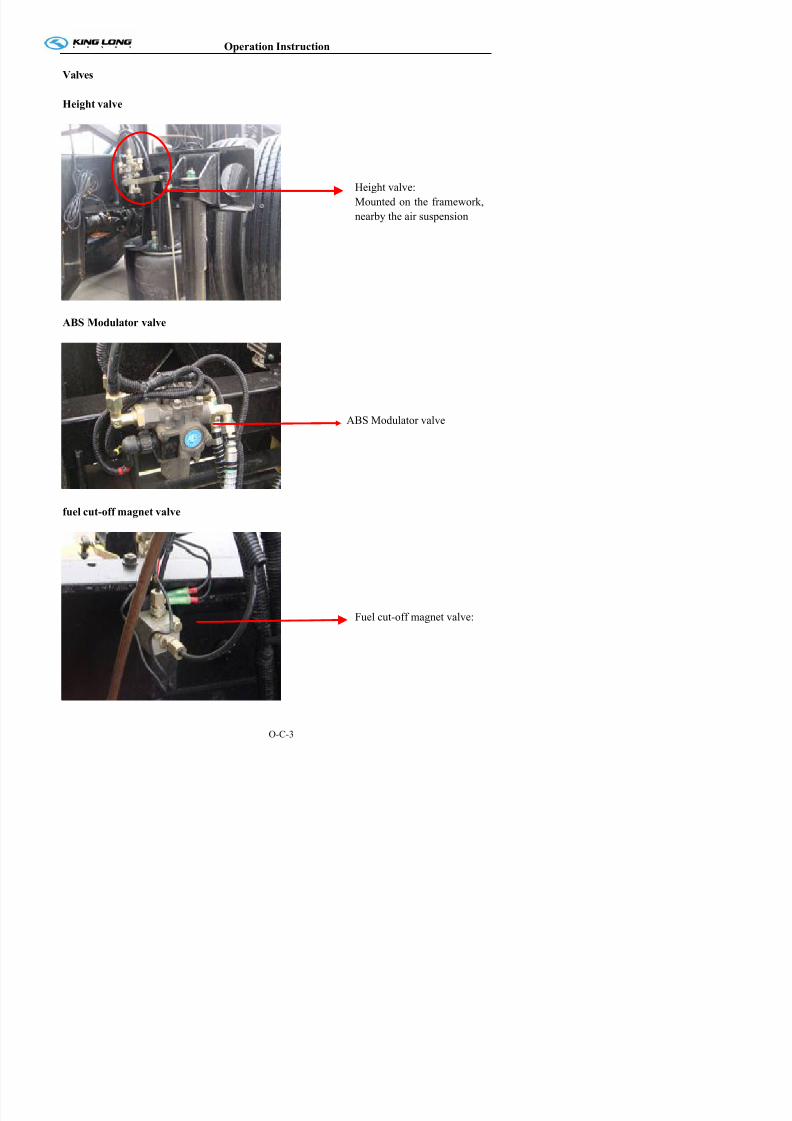
Valves
Height valve
Z
ABS Modulator valve
fuel cut-off magnet valve
Height valve:
Mounted on the framework,nearby the air suspension
ABS Modulator valve

7/21/2019 Xmq6117y3 Operation Manual _philippines 4 2014 Eb100072 81
http://slidepdf.com/reader/full/xmq6117y3-operation-manual-philippines-4-2014-eb100072-81 53/144
Operation Instruction
S it h
7/21/2019 Xmq6117y3 Operation Manual _philippines 4 2014 Eb100072 81
http://slidepdf.com/reader/full/xmq6117y3-operation-manual-philippines-4-2014-eb100072-81 54/144
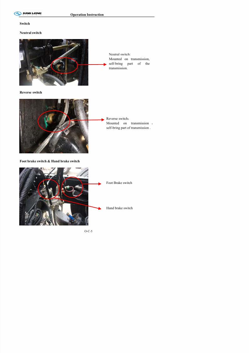
Switch
Neutral switch
Reverse switch
Foot brake switch & Hand brake switch
Neutral switch:
Mounted on transmission,
self-bring part of the
transmission.
Reverse switch:
Mounted on transmission ,
self-bring part of transmission .
Operation Instruction
Door pump switch

7/21/2019 Xmq6117y3 Operation Manual _philippines 4 2014 Eb100072 81
http://slidepdf.com/reader/full/xmq6117y3-operation-manual-philippines-4-2014-eb100072-81 55/144
Door pump switch
Door lamp switchAnti-clamp switchCentral door pump
Detail
Operation Instruction
C t l El t i it Di t ib t I t ll ti iti

7/21/2019 Xmq6117y3 Operation Manual _philippines 4 2014 Eb100072 81
http://slidepdf.com/reader/full/xmq6117y3-operation-manual-philippines-4-2014-eb100072-81 56/144
Central Electricity Distributor
The central electricity distributor always installed in thecompartment of the instrument desk.
The box integrates 50 chip-type fuses, 20 general and
special relays, and has 8 standby chip type fuses, one fuse
clip, which makes its construction more compact and
function more powerful. It improves design of the past
central electrical box, therefore it avoids weakness such as
unreliability and short service life, it applies integrated
circuit and designs 5 special relays: intermittent wiper
relay, turning flasher relay, lower water level warning
controller relay, monitor power relay, brake light failure
warning relay (when power supply voltage is lower than
23V, power supply of acoustic set and monitor is cut off
and will be begin to work again after power supply voltage
resumes to normal).
Installation position
Operation Instruction
Central Electricity Distributor (VITI)

7/21/2019 Xmq6117y3 Operation Manual _philippines 4 2014 Eb100072 81
http://slidepdf.com/reader/full/xmq6117y3-operation-manual-philippines-4-2014-eb100072-81 57/144
Central Electricity Distributor (VITI)
Layout of Fuses and Relays
Operation Instruction
Vehicle traveling data recorder

7/21/2019 Xmq6117y3 Operation Manual _philippines 4 2014 Eb100072 81
http://slidepdf.com/reader/full/xmq6117y3-operation-manual-philippines-4-2014-eb100072-81 58/144
g
The vehicle traveling data recorder is affixed to the right
side of the mounting panel for electrical equipment
inside instrument desk. When servicing it, open the
manhole cover under lower right side of instrument
desk.
Switch control box (Model: JKH2028)
Start switch Start relay
Fuse
40A
CAN administrative
module
Operation Instruction
The fan angle transmission mechanism

7/21/2019 Xmq6117y3 Operation Manual _philippines 4 2014 Eb100072 81
http://slidepdf.com/reader/full/xmq6117y3-operation-manual-philippines-4-2014-eb100072-81 59/144
g
This system has two benefits: first, it reduces
transmission noise, and second, it improves cooling
efficiency and requires only one belt instead of two.
Vehicle Starting and Driving
Preparatives for vehicle operation start up:
7/21/2019 Xmq6117y3 Operation Manual _philippines 4 2014 Eb100072 81
http://slidepdf.com/reader/full/xmq6117y3-operation-manual-philippines-4-2014-eb100072-81 60/144
Check daily, before turning engine on:
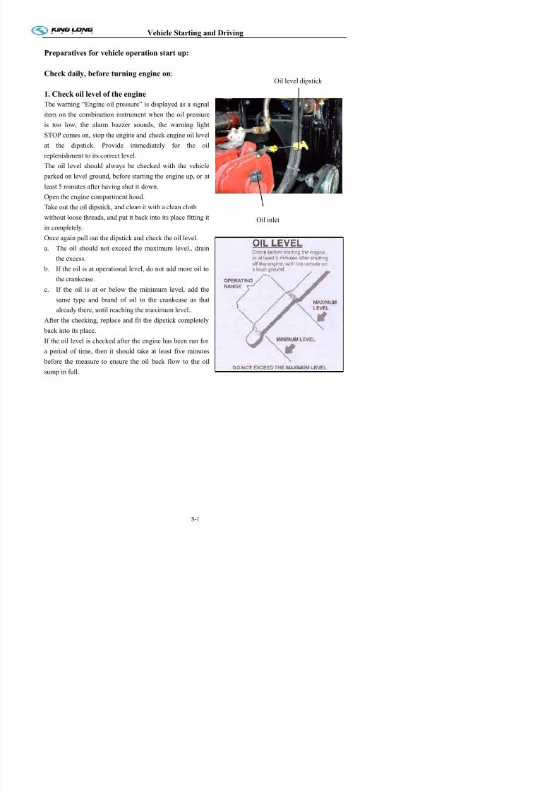
1. Check oil level of the engine
The warning “Engine oil pressure” is displayed as a signal
item on the combination instrument when the oil pressure
is too low, the alarm buzzer sounds, the warning light
STOP comes on, stop the engine and check engine oil level
at the dipstick. Provide immediately for the oilreplenishment to its correct level.
The oil level should always be checked with the vehicle
parked on level ground, before starting the engine up, or at
least 5 minutes after having shut it down.
Open the engine compartment hood.
Take out the oil dipstick, and clean it with a clean cloth
without loose threads, and put it back into its place fitting it
in completely.
Once again pull out the dipstick and check the oil level.
a. The oil should not exceed the maximum level.. drain
the excess.
b. If the oil is at operational level, do not add more oil to
the crankcase.
c. If the oil is at or below the minimum level, add the
same type and brand of oil to the crankcase as that
already there, until reaching the maximum level..
After the checking, replace and fit the dipstick completely
back into its place.
If the oil level is checked after the engine has been run for
a period of time, then it should take at least five minutes before the measure to ensure the oil back flow to the oil
sump in full.
Oil level dipstick
Oil inlet
Vehicle Starting and Driving
2 Check level of the coolant

7/21/2019 Xmq6117y3 Operation Manual _philippines 4 2014 Eb100072 81
http://slidepdf.com/reader/full/xmq6117y3-operation-manual-philippines-4-2014-eb100072-81 61/144
The coolant level is automatically monitored.
If coolant level gets too low,the digital indicator
displays a driver information on the combination
instrument. In this case, park vehicle in a safe place as
traffic conditions permit, stop engine and visually
check the coolant level.
Check the coolant level only when the engine doesn’t
work and its temperature is below 50℃.The anti-freezing rust-inhibiting engine coolant level
can be observed from the observe pipe.
The coolant level should be between the maximum
level (MAX.) and minimum (MIN.) level indicators in
the compensation tank.
If it is necessary to add coolant to the system:
a. Place the heating system command in the positionof maximum heating potency.
b. Add the coolant to the system up until the
maximum level indication. Only use coolant
which is recommended.
c. The compensation tank cover should not be
opened when temperature of the coolant is still
high to avoid being scalded Place the lid on the
system and turn it to the limit.
d. Pressure valve of the compensation tank should be
opened when adding the coolant to eliminate air in
coolant pipeline of the diesel engine.
e. Run the engine for a short time at varied rotations.
f. Stop the engine and check the coolant level.If necessary add more coolant to the system
Anti-freeze and antirust solution (mixture of glycol and water) should be added to cooling system from
time to time to avoid sediment frost oxidation and increase boiling point
Observe pipe
Observe pipe
Vehicle Starting and Driving
3 Fuel pre-filter with water separator (drain accumulated water)

7/21/2019 Xmq6117y3 Operation Manual _philippines 4 2014 Eb100072 81
http://slidepdf.com/reader/full/xmq6117y3-operation-manual-philippines-4-2014-eb100072-81 62/144
Draining accumulated water
On a daily basis, check the lower cup of the water
separator. If there is water in the cup, unscrew the
draining plug one or two turns, to drain the accumulated
water.
After draining the water, tighten the draining plug
correctly.
When the accumulation of impurities in the lower cup isnoticed, take the vehicle to a workshop to carry out its
cleaning.
Changing the fuel pre-filtering element
The fuel filtering element should be changed periodically,
at the intervals recommended in the maintenance manual.
If however, the filtering element is easily saturatedneeding substitution at very short intervals, this is an
indication of the accumulation of impurities in the
interior of the fuel tank, and the cleaning of the latter
should be carried out.
In order to change the fuel filter element, take the
vehicle to a Dealer or a King-Long Workshop.
Fuel system discharge
Activate the manual pump until feeling resistance on
pumping.
Start up the engine without accelerating. If the engine
does not start running in 20 seconds, interrupt the startup
and wait at least one minute before trying again.
If the engine insists on not working, repeat the discharge
operation.
Leave the engine running for about a minute to
completely eliminate the air from the system by way of
Model for Euro II
Model for Euro III IV
Manual pump
Release valve
Vehicle Starting and Driving
4. Fuel level

7/21/2019 Xmq6117y3 Operation Manual _philippines 4 2014 Eb100072 81
http://slidepdf.com/reader/full/xmq6117y3-operation-manual-philippines-4-2014-eb100072-81 63/144
Turn the ignition key to drive position (on).
Check the fuel level on the indicator. If necessary, fill up
the fuel tank. (but direct viewing by open the tank cover is
preferred).
Eliminate deposite water in diesel filter in time and check
fuel pipe for no leakage. Ensure sealing performance of fuel
tank and before opening fuel tank, wipe up clay and dirt.
Before filling up, shut down engine.Do not drive vehicle to empty tank. When the level
indicator is on the red bar, refuel the vehicle to avoid air
from entering the fuel system.
Fill the tank only with good quality fuel free of
contaminants. The fuel might as well be filled up when
running in the humid area to avoid inner rustiness.
Vehicle Starting and Driving
5. Vehicle lighting, intermittent lights and brake lights

7/21/2019 Xmq6117y3 Operation Manual _philippines 4 2014 Eb100072 81
http://slidepdf.com/reader/full/xmq6117y3-operation-manual-philippines-4-2014-eb100072-81 64/144
Check all instruments and indicator lamps for normal, especially the head lamp, the turning lamp, the brake
lamp, the reversing lamp and the danger alarm lamp.Check the bulb and the switch for their damage. To carry out the lamp substitution, hands should be very
clean. If possible handle new lamps with tissue paper.
Clean the external of all instruments and indicator lamps to ensure clear indication.
Attention!
The traffic laws regulate the location, lighting intensity, and color of the lenses and the quantity of
lanterns for each type of vehicle. The King-Long vehicles leave the factory in strict obeyance of thesespecifications. Traffic safety depends on these factors; therefore do not change the place of the lanterns.
Substitute the damaged lanterns only for other original ones. Remember that a change of lantern colors
can confuse other motorists and result in serious accidents. Avoid unnecessary lantern adaptations.
When substituting lamps, use the same type and potency as the original lamps. Do not carry out any
lamp adaptation in the headlights, as this will affect their adjustment and performance, putting the
vehicle traffic safety at risk.
On a regular basis revise the illumination system, keeping it always in perfect working conditions.
Vehicle Starting and Driving
7. Drain water in air tank
Open the water drain valve of air tank to drain oily water fully If too much oily water is bled check to

7/21/2019 Xmq6117y3 Operation Manual _philippines 4 2014 Eb100072 81
http://slidepdf.com/reader/full/xmq6117y3-operation-manual-philippines-4-2014-eb100072-81 65/144
Open the water drain valve of air tank to drain oily water fully. If too much oily water is bled, check to
see if desiccant needs to be replaced in air drier. (This may be avoided when adopting the automatic drain
valve but it should be checked every two weeks)
Vehicle Starting and Driving
Check daily after turning engine on:

7/21/2019 Xmq6117y3 Operation Manual _philippines 4 2014 Eb100072 81
http://slidepdf.com/reader/full/xmq6117y3-operation-manual-philippines-4-2014-eb100072-81 66/144
1. engine oil pressure
Run the engine.
The information on engine oil pressure can be requested through the driver information digital display.
If the oil pressure is too low, the oil pressure is automatically shown on the combination instrument.
Indication of the oil gauge will show a high value after the cold start of the engine and then it should be
kept within the range of 0.3-0.5Mpa (3- 5kg/cm2) along with the increment of the oil temperature as well
as the normal engine speed.
Vehicle Starting and Driving
2. Pneumatic pressure
7/21/2019 Xmq6117y3 Operation Manual _philippines 4 2014 Eb100072 81
http://slidepdf.com/reader/full/xmq6117y3-operation-manual-philippines-4-2014-eb100072-81 67/144
The air pressure gauge indicates the reserve pressure individually for the front and rear service brake
circuits.
The reserve air pressure in each brake circuit must be sufficient for the correct operation of the brake
system.
The STOP warning light comes on in case of low brake pressure in the service brake or parking brake
circuits.
Attention!If the driver information indicator displays the warning “brake pressure” and the STOP warning light
comes on with the engine running, it will be an indication that the air pressure is excessively low. Do not
drive the vehicle if the air pressure gauge displays low air pressure in one or both brake circuits, as the
service brake could fail resulting in serious accident.
Vehicle Starting and Driving
3. Tachograph working order
7/21/2019 Xmq6117y3 Operation Manual _philippines 4 2014 Eb100072 81
http://slidepdf.com/reader/full/xmq6117y3-operation-manual-philippines-4-2014-eb100072-81 68/144
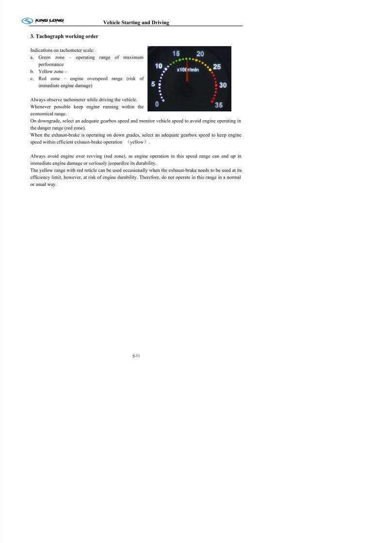
Indications on tachometer scale:
a. Green zone – operating range of maximum
performance
b. Yellow zone –
c. Red zone – engine overspeed range (risk of
immediate engine damage)
Always observe tachometer while driving the vehicle.
Whenever possible keep engine running within the
economical range.
On downgrade, select an adequate gearbox speed and monitor vehicle speed to avoid engine operating in
the danger range (red zone).
When the exhaust-brake is operating on down grades, select an adequate gearbox speed to keep engine
speed within efficient exhaust-brake operation (yellow).
Always avoid engine over revving (red zone), as engine operation in this speed range can end up in
immediate engine damage or seriously jeopardize its durability.
The yellow range with red reticle can be used occasionally when the exhaust-brake needs to be used at its
efficiency limit, however, at risk of engine durability. Therefore, do not operate in this range in a normal
or usual way.
Vehicle Starting and Driving
4. Steering play
7/21/2019 Xmq6117y3 Operation Manual _philippines 4 2014 Eb100072 81
http://slidepdf.com/reader/full/xmq6117y3-operation-manual-philippines-4-2014-eb100072-81 69/144
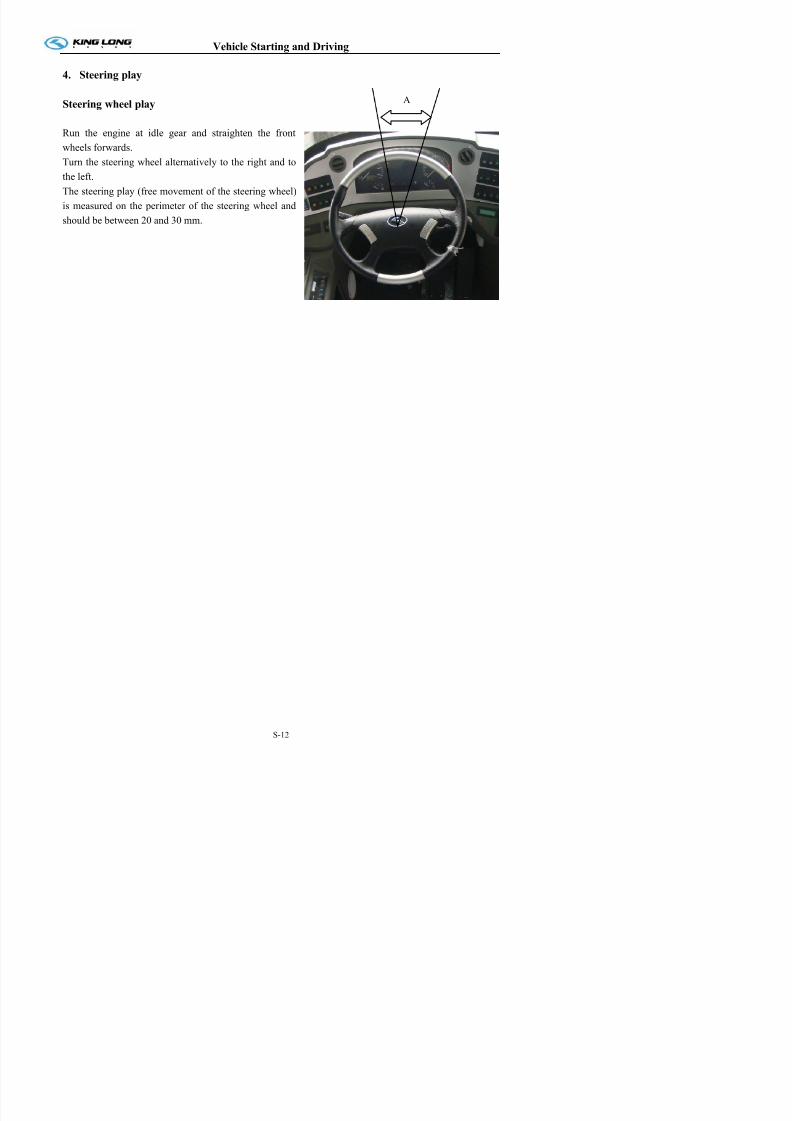
Steering wheel play
Run the engine at idle gear and straighten the front
wheels forwards.
Turn the steering wheel alternatively to the right and to
the left.
The steering play (free movement of the steering wheel)
is measured on the perimeter of the steering wheel and
should be between 20 and 30 mm.
A
Vehicle Starting and Driving
Control periodically, at least once a week:

7/21/2019 Xmq6117y3 Operation Manual _philippines 4 2014 Eb100072 81
http://slidepdf.com/reader/full/xmq6117y3-operation-manual-philippines-4-2014-eb100072-81 70/144
1. Check tire for abrasion and pressure and tire nut for fixture
The vehicle’s safety and performance depend considerably on the state of the tires, reason why they
should be checked daily.
Before driving a vehicle, check charging pressure of tire for normal, tire for damage, tire nut for fixture.
Note: At initial 50km, please tighten tire nuts of new vehicle to specified torque in appendix.
Tire pressure
Keep the tires always correctly calibrated. The inflation pressure should be checked with the tires cold at
least once a week.
After driving the vehicle for some time, the tires heat and in consequence of the heat, the inflation
pressure increases. Never, under any circumstance, empty heated tires to reestablish the recommended
inflation pressure.
The pressure difference between the assemble tires on the same axle should not be superior to 0.1 bar.
Wheel hubs
Keep them always clean, eliminating eventual mud or other dirt adherence. Substitute the damaged and/or
deformed hubs. The utilization of refurbished hubs is not recommended.
Wheel nut
Without fail re-tighten the wheel fastening nuts of new vehicles after running 50km.
The wheel fastening nuts should be retightened, crosswise, in turns, observing the recommended
tightening torque according to the type of fastening nut. If a torque meter is not available, tighten the nuts
strongly, using the vehicle tools without additional levers.
Vehicle Starting and Driving
2. Air cleaner (activate the dust discharge valve to loosen accumulated dust)
Model 1

7/21/2019 Xmq6117y3 Operation Manual _philippines 4 2014 Eb100072 81
http://slidepdf.com/reader/full/xmq6117y3-operation-manual-philippines-4-2014-eb100072-81 71/144
The maintenance of the air cleaner is made up of the
substitution of the filtering elements and should be
done only when the maintenance indicator indicates
the saturation of the element.
The cleaning of the main and safety filtering elements
is not recommended. The re-utilization of the filtering
elements can result in deficient filtering of the air and
cause serious damage to the engine.
When washing the engine, conveniently protect the air
inlet with a plastic or similar material to avoid the
infiltration of water to the air filtering element. After
washing the engine, remove the protection from the air
inlet.
Periodically press the dust discharge valve with yourhand, in order to incomplete the dust which possibly
be caught in the internal part maintaining them clear.
At the same time, check clip connecting rubber hose
of air intake system with steel tube in case of dust
entering air intake system due to looseness and
decrease in engine life.
The air cleaner restriction is electronically controlled.
If the indication of saturated air cleaner appears in the
display of digital indicator in combination instrument,
send the vehicle to a King-Long Dealer or authorized
workshop to inspect and clean the air intake system
and substitute the main filtering element.
Indication
The main filtering element of the air filter should be substitutes after maximum 2 years use.
The safety filtering element (optional) should be changed at every third main filtering element
substitution or after maximum 2 years of use
Model II
1 automatic dust discharge valve
Vehicle Starting and Driving
3. General leakages (water, oil, fluids and fuel)

7/21/2019 Xmq6117y3 Operation Manual _philippines 4 2014 Eb100072 81
http://slidepdf.com/reader/full/xmq6117y3-operation-manual-philippines-4-2014-eb100072-81 72/144
Check the engine, the transmission, the driving axle, the steering system, the cooling system and the oil
pipeline, the air pipeline of the complete vehicle for their leakage.
Vehicle Starting and Driving
4. Fastening and state of seat belts
Ch k b kl f th f t b lt f th d i t f l d f it l k d th f ll i

7/21/2019 Xmq6117y3 Operation Manual _philippines 4 2014 Eb100072 81
http://slidepdf.com/reader/full/xmq6117y3-operation-manual-philippines-4-2014-eb100072-81 73/144
Check buckle of the safety belt of the driver seat for normal and ensure for its lockup under the following
situations when fastening the safety belt.● The body dashes forward all of a sudden;
● The vehicle makes an emergency braking or an abrupt acceleration;
Vehicle Starting and Driving
5. Check emergency devices and driver’s tools
S h ti i h ti f bl ki hi l h j k d t

7/21/2019 Xmq6117y3 Operation Manual _philippines 4 2014 Eb100072 81
http://slidepdf.com/reader/full/xmq6117y3-operation-manual-philippines-4-2014-eb100072-81 74/144
Such as extinguisher, crosstie for blocking vehicle, emergency hammer, jack and etc..
Fire extinguisher:
The pulse super-micro powder fire extinguisher is fixed
in the engine compartment, when the compartment is on
fire, the fire extinguisher activate automatically or is
active by manual work to eradicate the fire
The fire button is usually located at auxiliary instrument
desk in the driver compartment where people couldoperate it easily.
Operation:1. When the engine compartment caught fire,
the driver should stop vehicle and switch off engine
immediately, open the fire button cover, and press the
fire button, start-up fire extinguisher
2.Fire extinguisher may start-up automatically when
it catches fire or its temperature arrives at 170℃.
Important hint:
1. Fire extinguisher can be used for one time only,
DO NOT press the fire button except for
emergency condition.
2. The fire extinguisher can not start–up by press the
fire button manually if the vehicle battery is dead or
Fire extinguisher
Fire button
Vehicle Starting and Driving
6. Working order of windshield wipers and conditions of wiper blades and arms
Regularly check the windshield wiper blades for dirt or damageModel 1
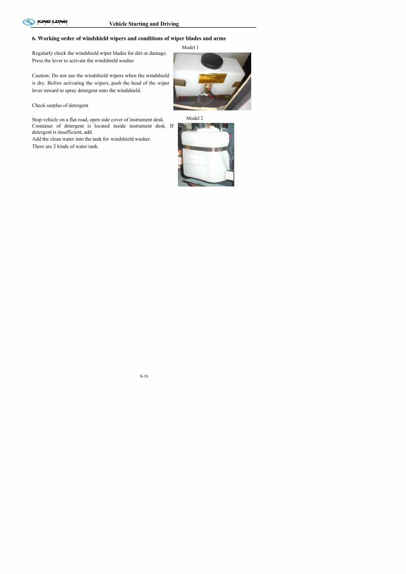
7/21/2019 Xmq6117y3 Operation Manual _philippines 4 2014 Eb100072 81
http://slidepdf.com/reader/full/xmq6117y3-operation-manual-philippines-4-2014-eb100072-81 75/144
Regularly check the windshield wiper blades for dirt or damage.
Press the lever to activate the windshield washer
Caution: Do not use the windshield wipers when the windshield
is dry. Before activating the wipers, push the head of the wiper
lever inward to spray detergent onto the windshield.
Check surplus of detergent
Stop vehicle on a flat road, open side cover of instrument desk.
Container of detergent is located inside instrument desk. If
detergent is insufficient, add.
Add the clean water into the tank for windshield washer.
There are 2 kinds of water tank.
Model 2
Vehicle Starting and Driving
7. Electrical rearview mirror
Check adjust and clean the rearview mirror

7/21/2019 Xmq6117y3 Operation Manual _philippines 4 2014 Eb100072 81
http://slidepdf.com/reader/full/xmq6117y3-operation-manual-philippines-4-2014-eb100072-81 76/144
Check, adjust and clean the rearview mirror.
Rearview mirror control button
Model 1
L: adjusting left rearview mirror.
R: adjusting right rearview mirror.
Mirror button: push down the arrow headed button to
adjust the mirror for 4 directions.
Model 2L: adjusting left rearview mirror.
R: adjusting right rearview mirror.
Mirror button: rotate the handle to adjust the mirror for
4 directions.
Model 2
Model 1
Model 3
Vehicle Starting and Driving
Inspection every two weeks before and after driving
1 Power steeringModel 1

7/21/2019 Xmq6117y3 Operation Manual _philippines 4 2014 Eb100072 81
http://slidepdf.com/reader/full/xmq6117y3-operation-manual-philippines-4-2014-eb100072-81 77/144
1. Power steering
Ensure that all the maintenance service jobs on the steering
system be carried out at the intervals recommended in the
maintenance manual to guaranty total efficiency and safety.
If any working abnormality in the steering is noticed,
immediately supply the necessary repairs.
The habits of forcing the steering too far against wheel
obstacles and of activating the steering while the vehicle is
stopped are harmful to the steering system and should be
avoided.
In emergencies, in the case of damage to the power steering
system, the steering may be used without hydraulic help,
however, in this condition there will be more steering wheel
play and the steering will become noticeably “heavier”. Drivethe vehicle very carefully and take it to an authorized
King-Long Dealer or Workshop to re-establish the correct
working order of the steering system.
Important: In the case of damage to the hydraulic steering
pump or of the total loss of fluid from the hydraulic system,
we recommend that the vehicle is not driven further than
50KM in order to avoid further damage to the steering system
components.
Power steering fluid level
The power steering fluid level should be checked while the
engine is running at idle and the fluid is hot. Run the engine at
idle gear and turn the steering from side to side various times
to heat the steering system fluid.
Check the level through the inspect window of the container.
Model 2
Model 3
Vehicle Starting and Driving
2. Clutch actuation system fluid level
Clutch

7/21/2019 Xmq6117y3 Operation Manual _philippines 4 2014 Eb100072 81
http://slidepdf.com/reader/full/xmq6117y3-operation-manual-philippines-4-2014-eb100072-81 78/144
Clutch
The clutch activating system can present irregular working due to the normal wear of the clutch disc.
When suspecting that the clutch disc has reached the wear limit, take the vehicle to a King-Long
authorized Dealer or Workshop to carry out the necessary repairs.
Clutch fluid level
The clutch oil tank is installed in the instrument desk.
Prevent the brake fluid used in the clutch activating
system, from entering into contact with the vehicle’s
plastic components or painted surfaces. In the case of
spilling or accidental dripping, immediately clean the
affected surface with cold water to avoid damage tothese components or to the vehicle paint.
The fluid level in the clutch activating system
container should be between the maximum and
minimum level indications. If there is a need to add
fluid to the container, take the vehicle to check the
impermeability of the hydraulic system. Aftereliminating any leaks, fill the container up to the
maximum level and bleed the hydraulic system.
Vehicle Starting and Driving
3. General state and tension of drive belts
Check the tension of engine belt, fan belt and compressor belt, if loose, tension it; if damaged, replace it.

7/21/2019 Xmq6117y3 Operation Manual _philippines 4 2014 Eb100072 81
http://slidepdf.com/reader/full/xmq6117y3-operation-manual-philippines-4-2014-eb100072-81 79/144
g , p , , ; g , p
Do not start up the engine without the drive belts. In the case of one of the belts breaking, immediately
stop the engine and have a new belt put in.
The checking, adjustment or substitution of the drive belts should be carried out with the engine shut
down.
Check cross plane of the belt for no cracks. Crackle in the transverse direction (along the belt width
direction) is acceptable while that in longitudinal direction and transverse crack cross is unacceptable.
Please replace the strap in case of abrasion or chip dropping off.
Too tight or too loose belt would make against proper operation of engine. Press belt to check tension.
Please refer to the manual book of engine assembly for detailed adjusting method and tension of belt.
The poli-V belts demand technical knowledge, therefore we recommend that this job, when necessary, be
carried out at a King-Long authorized Dealer or Workshop.
Ventilator drive belts
If it is necessary to replace the ventilator drive belts in emergency situations, adjust their tension in such a
way that upon pressing them with one’s thumb in the middle of the distance between the pulleys, a
defection of approximately 20mm is observed. Loosen fastening nut of intermediary pulley before turning
the adjusting bolt. After adjusting ventilator belt tension, tighten the fastening nut of intermediary pulley
firmly.
Model 1:Adjusting method of the single belt driving fan belt is
shown in the figure
1. Check tension of belt
Apply force of 98N by the finger.
Strap sinkage between the crank pulley 1 and the fan
pulley 2 should be 25 ~ 31mm.
2. Adjust tension of cone beltAdjust bolt 3 until the tension is proper.
The max offset angle of the fan pully shaft should not
exceed 5°, or else please replace it.
1 2 3
Vehicle Starting and Driving
Air conditioning compressor drive belt
The pneumatic tensioning system keeps the tension of air conditioning compressor drive belt correctly

7/21/2019 Xmq6117y3 Operation Manual _philippines 4 2014 Eb100072 81
http://slidepdf.com/reader/full/xmq6117y3-operation-manual-philippines-4-2014-eb100072-81 80/144
adjusted and do not need to be adjusted periodically.
Adjusting method of the air conditioner belt is shown in
the figure
1 Check tension of belt
Apply 98N force to belt with finger
Belt crank pulley 4 and middle pulley 2 should lower
10~15mm
2. Adjust tension of cone belt
Adjust nut 1until tension of belt is proper
1 2 4
Vehicle Starting and Driving
4. Check level of battery electrolyte
Open the battery cover to check level of electrolyte, if the level is lower than scale marked on the battery,
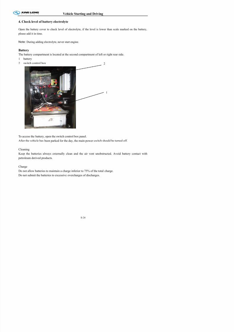
7/21/2019 Xmq6117y3 Operation Manual _philippines 4 2014 Eb100072 81
http://slidepdf.com/reader/full/xmq6117y3-operation-manual-philippines-4-2014-eb100072-81 81/144
please add it in time.
Note: During adding electrolyte, never start engine.
Battery
The battery compartment is located at the second compartment of left or right rear side.
1 battery
2 switch control box
To access the battery, open the switch control box panel.
After the vehicle has been parked for the day, the main power switch should be turned off.
CleaningKeep the batteries always externally clean and the air vent unobstructed. Avoid battery contact with
petroleum derived products.
1
2
Vehicle Starting and Driving
Engine start up and shut down
Procedures for engine start up

7/21/2019 Xmq6117y3 Operation Manual _philippines 4 2014 Eb100072 81
http://slidepdf.com/reader/full/xmq6117y3-operation-manual-philippines-4-2014-eb100072-81 82/144
Activate parking brake.
Place the gear box lever in neutral. Start up is not possible in gear position.
Turn the ignition key into gear position.
Start up without stepping on the accelerator. If the engine does not work after about 20 seconds, interrupt
the start up process and wait at least 15 seconds before activating start again. To repeat start up, it is
necessary to turn the key back to the off position.
Let the ignition key loose as soon as the engine starts running.
The motor rotation adjusts itself automatically in function of the coolant temperature.
Indication:
The start up process is automatically interrupted after 90 seconds of continuous activation. In this case, in
order to repeat the start up activation, turn the ignition key back to the off position and wait at least 2
minutes.
After engine start up, the vehicle can be put immediately into operation.
Note:
a. The engine should be running at low middle speed for 3-5 minutes on every day's first starting before the
driving.
b. Never race the engine without warming up. During cold start, increase engine speed slowly and do not
make engine run at maximum speed until water temperature of engine reaches to 70°C. At any time, do not
make engine run at high speed under no load.
c. Never make engine run at idle speed for more than 10 minutes.d. The oil pressure should be displayed on the dashboard in 15 seconds after the engine is started, otherwise,
stop engine to check..
e. If parking brake indicator lights, indicating that parking brake has not be released.
Attention!
If on starting up the engine, the engine oil pressure indicator continues indicating low pressure, this meansthat the engine running order is in danger. Immediately shut down engine, find and correct the failure.
Vehicle Starting and Driving
Engine shut down
Loosen accelerator pedal.

7/21/2019 Xmq6117y3 Operation Manual _philippines 4 2014 Eb100072 81
http://slidepdf.com/reader/full/xmq6117y3-operation-manual-philippines-4-2014-eb100072-81 83/144
Place the gear box lever in neutral position and apply the parking brake.
Turn the ignition key to the off position, without accelerating.
Note: After engine runs at heavy loading, temperature of cooling water is higher than 90ºC, so do not stop
engine at once. The stalling should be made only after the engine has been running for a period of time and the
water temperature lowed to the normal range. The parking brake is achieved by setting the hand brake handle
on the control position after the stalling. The shift should be switched to the neutral position and power supply
shut down. Please make necessary inspection of engine and then troubleshoot.
Cautions
Cautions during the winter operation
① Please add long life coolant to cooling system.
② After parking, please exhaust water in air tank in time.
③ Before winter comes, please check level of battery electrolyte, specific gravity and voltage.
Water used in the radiator must be soften.
Never make engine start without preheating or run with trouble. In the cold climate, do not start engine until
preheat it with hot water or vapor to more than 30-40ºC.
During driving downhill, do not place gearshift lever in neutral position to slip. Please apply exhaust brake or
retarder.
Do not start vehicle until parking brake has been released
Vehicle Starting and Driving
Engine start up and shut down in the engine compartment
Park the vehicle and activate the parking brake.
Put the gear box lever or the automatic transmission
Model 1

7/21/2019 Xmq6117y3 Operation Manual _philippines 4 2014 Eb100072 81
http://slidepdf.com/reader/full/xmq6117y3-operation-manual-philippines-4-2014-eb100072-81 84/144
g
selector in neutral (dead point).
If the transmission is in gear position, the start up with in
the engine compartment will not work.
Turn the ignition key to gear position, without activating
engine start up.
Engine start up
Press the start up switch (start) and activate the backcover course end switch bar in the engine compartment.
Loosen the switches immediately the engine begins
running.
When the engine is turned on by way of the start up
switch in the engine compartment, this switch should be
used as a manual accelerator.
With the engine compartment cover open, the start up byway of the ignition key is impossible.
Engine shut down:
Press the shut down switch (STOP).
To make the engine turn without starting up:
Press the engine start up and shut down buttons
simultaneously.
Note: the final placement of the switches in the engine
compartment is the responsibility of the vehicle body
manufacturer.
Model 2
Model 3
Vehicle Starting and Driving
Starting the vehicle
The vehicle could only be started when braking system pressure has reached 5kg/cm2 above and each
instrument and indicator lamp is on the proper condition, and water outlet temperature exceeds 60℃ as well
7/21/2019 Xmq6117y3 Operation Manual _philippines 4 2014 Eb100072 81
http://slidepdf.com/reader/full/xmq6117y3-operation-manual-philippines-4-2014-eb100072-81 85/144
p p p p
as the parking brake has been released after the engine is started. Please make the startup in shift I.
On normal running condition:
Pointer of oil gauge should be between 0.3 and 0.5Mpa(3-5kg/cm2).
Pointer of water temperature gauge should be between 83℃ and 95℃.
Pointer of double-pointer barometer should be between 0.55 and 0.8 Mpa(5.5-8kg/cm2)
After the vehicle starting, gear shifting should be made step by step and timely. The clutch pedal should not be
released abruptly to impulse the starting when the vehicle is stuck in the mud or can not start on a spoil road.
The following problems should also be paid attention to during the driving① If abnormal noise or odor occurs, please stop vehicle to check.
② Abrupt acceleration or emergency braking should be avoided as might.
③ Don't put foot on the clutch pedal during the driving.
④ Avoid engine overspeed. When driving long downhill, engine may overspeed easily after gearshift, at
this time, pay attention to apply exhaust brake or retarder and driving brake to ensure engine run at
specified speed.
⑤During driving downhill, never stop engine, otherwise, resulting in de-pressure in brake pipeline and power steering gear failure.
During normal running condition,if the pointer of water temperature gauge is under the red sign that indicated
the vehicle is on normal condition. if the pointer is on “H”
Vehicle Starting and Driving
Parking the vehicle
The parking brake should be always applied when the vehicle is parked.

7/21/2019 Xmq6117y3 Operation Manual _philippines 4 2014 Eb100072 81
http://slidepdf.com/reader/full/xmq6117y3-operation-manual-philippines-4-2014-eb100072-81 86/144
Additionally, in some countries, it is determined by law that a vehicle parked on a slope must have at leastone of its wheels wedged, to prevent its accidental moving.
In this case, always keep an appropriate wedge available for this purpose aboard the vehicle.
When parking on public highways, obey the legal determinations as far as the use of parking lights or
reflecting panels.
Parking brake handle
Pushing forward the brake handle is of driving state.
Pushing backward the brake handle is of parking state.
Always activate the parking brake when the vehicle is
parked.
Besides activating the parking brake, when parking on
upward or downward slopes, wedge one of the vehicle
wheels to avoid the accidental moving of the vehicle.
Application
Attention!
On applying the parking brake, always check the
locking of the lever in the total braking position, onthe contrary, the lever may return automatically to the
brake off position.
Pull back the parking brake valve lever in such a way
that the lever is locked in total braking position. The
parking brake warning light should light up.
Note:
In emergencies, with the possible failure of the service
brake, the parking brake can be used as an emergency
brake In this case slowly pull the parking brake lever
Maintenance and service
General knowledge
King Long recommends that the bus be maintained according to the Maintenance Schedule in this section.
P f i t t hi h i t l fi t At h h d l d i t i t l f ll

7/21/2019 Xmq6117y3 Operation Manual _philippines 4 2014 Eb100072 81
http://slidepdf.com/reader/full/xmq6117y3-operation-manual-philippines-4-2014-eb100072-81 87/144
Perform maintenance at whichever interval occurs first. At each scheduled maintenance interval, perform all previous maintenance checks they are due for scheduled maintenance.
King-long Bus General Maintenance
Please make periodic inspection and maintenance of bus according to the operation manual to ensure good
status. During service, stop bus on a horizontal road and ensure bus steady and engine stopping. Make
functional inspection and running test after each service.
Important Notice: If bus often runs under poor conditions (such as poor road surface, high dust
concentration, frequent bump etc.), maintenance interval should be shortened. During adding lubricant,
before replacing filter or repairing, clean the place around related parts carefully. Please add lubricant with
clean containers.
Maintenance of engine and chassis assembly
• For the usage and maintenance of the engine, refer to relevant engine operation and maintenance
manual.
• For maintenance of transmission and front-rear axle, please refer to relative users’ guide.
• For use and maintenance of other parts of chassis, if without special user’s guide or maintenance period,
please refer to this manual for maintenance information.
Body maintenance
1. Keep body clean .Timely clean should be made after daily running and don’t scrape body with tool in
order to avoid paint scratch and damage of roll covering.
2. Sealing strips of doors and windows should be kept integrated. Make timely replacement if damaged.
3. Prohibit washing body paint with hot water, buck, kerosene and other liquid which has damage to oil
paint.
4. Check connections between body and frame frequently. If find something abnormal, repair it in time.
5 Frequently check fasteners inside vehicle and tighten them in time
Maintenance and service
4. When maintain the brake shoe ,do not damage the ring gear and sensor, clean the ring gear and
sensor at the same time. after maintenance ,do remember to put the sensor to the limited position
along the ring gear direction.
5 M k th t th i i ff iti h d i t ll th t k th

7/21/2019 Xmq6117y3 Operation Manual _philippines 4 2014 Eb100072 81
http://slidepdf.com/reader/full/xmq6117y3-operation-manual-philippines-4-2014-eb100072-81 88/144
5. Make sure that the power is in off position when remove and install the components, keep thecomponents clean and dry.
6. Never change the fuse capability or connect the fuse in disorder.
7. Change the indicator in time when it doesn’t work.
8. Do not brush the ECU with water when cleaning it.
Note: for details about the working theory of ABS and maintenance, please refer to the ABS instruction
book which is offered by provider.
Because of different allocation requirements, some of the vehicle model may not be equipped with ABS
system, please use correctly according to actual condition of vehicle.
Electrical system maintenance and service:
(1) When battery is charged by external power supply, disconnect ECU control box to prevent outer
high voltage damage ECU (electric control unit).
(2) When vehicle needs to weld, disconnect ECU. Don’t use multimeter to measure ECU control box.
(3) Monitor voltage stability of generator regularly.
(4) Parts dismantling must be carried out after electric has been shut off and should keep parts’
cleanness and dry.
(5) Don’t change fuse capacity casually or bestride connect fuse.
(6) When indicator doesn’t work, replace it timely.(7) Don’t use water to scour ECU when doing ECU cleanness.
(8) Don’t use multimeter to measure ECU.
Tire transposition
The tire may appear certain abrasion after period of running. The tire should be made transposition as
the drawing below after every 8000 km to 10000 km running for proper use and prolonged tire life.Four-wheel locating condition should be checked, dynamic balance and tire transposition be made at
once if there shows early and irregular abrasion of the tire.
Maintenance and service

7/21/2019 Xmq6117y3 Operation Manual _philippines 4 2014 Eb100072 81
http://slidepdf.com/reader/full/xmq6117y3-operation-manual-philippines-4-2014-eb100072-81 89/144
Tire transposition diagram(three axles)
Adjustment of the clutch pedal free play
Adjust clearance between push rod and piston of clutch master cylinder to 0.2-0.7mm. Loosen locknut
and rotate push rod along the piston direction until it contacts the piston, and then turn back 1/7-1/2
circle. After adjustment, tighten the locknut and then adjust the length of clutch booster push rod to
ensure 4-6mm empty stroke. At this time, clutch pedal free stroke is 8-12mm
Adjustment of the brake pedal free play
Loosen locknut of brake pedal push rod and adjust adjusting nut, and then measure the vertical distance
from pedal free position to the position where pressing resistance increases apparently when depressing
pedal. The value should be between 8mm and 12mm. After adjustment, lock the locknut.
Bus cleaning
• Don’t pollute the environment when washing vehicle at washing shop.
• Be careful to use the high strength dissolve fluid
Maintenance and service
Cleaning the air filter
Hint: Please replace filter element under such conditions:
it has been washed 5 times; filter element has been
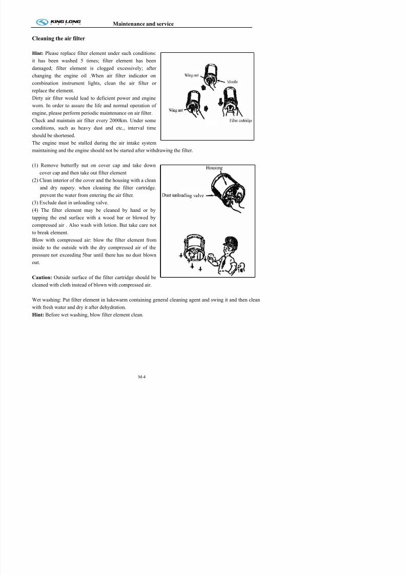
7/21/2019 Xmq6117y3 Operation Manual _philippines 4 2014 Eb100072 81
http://slidepdf.com/reader/full/xmq6117y3-operation-manual-philippines-4-2014-eb100072-81 90/144
it has been washed 5 times; filter element has beendamaged; filter element is clogged excessively; after
changing the engine oil .When air filter indicator on
combination instrument lights, clean the air filter or
replace the element.
Dirty air filter would lead to deficient power and engine
worn. In order to assure the life and normal operation of
engine, please perform periodic maintenance on air filter.
Check and maintain air filter every 2000km. Under some
conditions, such as heavy dust and etc., interval time
should be shortened.
The engine must be stalled during the air intake system
maintaining and the engine should not be started after withdrawing the filter.
(1) Remove butterfly nut on cover cap and take down
cover cap and then take out filter element
(2) Clean interior of the cover and the housing with a clean
and dry napery. when cleaning the filter cartridge.
prevent the water from entering the air filter.
(3) Exclude dust in unloading valve.
(4) The filter element may be cleaned by hand or bytapping the end surface with a wood bar or blowed by
compressed air . Also wash with lotion. But take care not
to break element.
Blow with compressed air: blow the filter element from
inside to the outside with the dry compressed air of the
pressure not exceeding 5bar until there has no dust blown
out.
Caution: Outside surface of the filter cartridge should be
cleaned with cloth instead of blown with compressed air
Maintenance and service
Caution: Vapor spray gun, solution, gasoline or equivalent should not be used during the cleaning.
-Before reinstalling air filter element, check element from inside to outside with check lamp for
damage;
Check sealing ring for damage or cracks

7/21/2019 Xmq6117y3 Operation Manual _philippines 4 2014 Eb100072 81
http://slidepdf.com/reader/full/xmq6117y3-operation-manual-philippines-4-2014-eb100072-81 91/144
-Check sealing ring for damage or cracks.
Caution: Do not start the engine without mounting the air filter.
Clean outside of the radiator
Keep outside of radiator clean. Compressed air current can eliminate all the dirt blocking air flow.
For vehicle equipped with intercooler, please keep air radiator fin clean. If there is hard dirt in radiator
fin, blow fan side and then the other side with compressed vapor current. In order to avoid damage to
air radiator fin or water radiator fin, ensure spray of air, water or vapor perpendicular to radiator surface.
It should be sent to the king-long special maintenance station to make decontamination and final
disposal if there has much dirt in the water radiator and the air radiator.
1. Clean water radiator fin and air radiator fin termly and eliminate dirt blocking air flow, which is
important for ensuring the engine cooling.
2. For zone with many winged insect, please clean radiator fin frequently.
3. If users do not operate according to requirement, resulting in poor engine cooling and grave
damage to components.
4. If don’t comply with this requirement, it may cause poor engine cooling and bad damage to
components.
5. Anti-freeze and antirust solution (mixture of glycol and water) should be added to cooling system perennially to avoid sediment, frost, oxidation and increase boiling point.
Note: When adding coolant, please choose the same model as much as possible in case of sediment. If
coolant is degenerative, replace it entirely and immediately.
6. Never use water to replace coolant for a long period.
After long running of engine, scale will come into being in cooling system. It should be eliminated in
time. Methods as follows: mix 700-800g caustic soda with 150g kerosene and then inject the mixed
liquid into cooling water and make engine run at middle speed for 5-10 minutes. 10-12 hours later,
make engine run again for 10-15 minutes and then drain aqueous solution and clean cooling system
with clean water.
Maintenance and service
below: mix 700-800g caustic soda with 150g kerosene and then inject the miscible liquids into water, at
this time, make engine run at middle speed for 5-10 minutes. 10-12 hours later, make engine run again
for 10-15 minutes and then drain aqueous solution and clean cooling system with fresh water. Coolant
specification as shown below: the users should choose proper brand according to requirement:
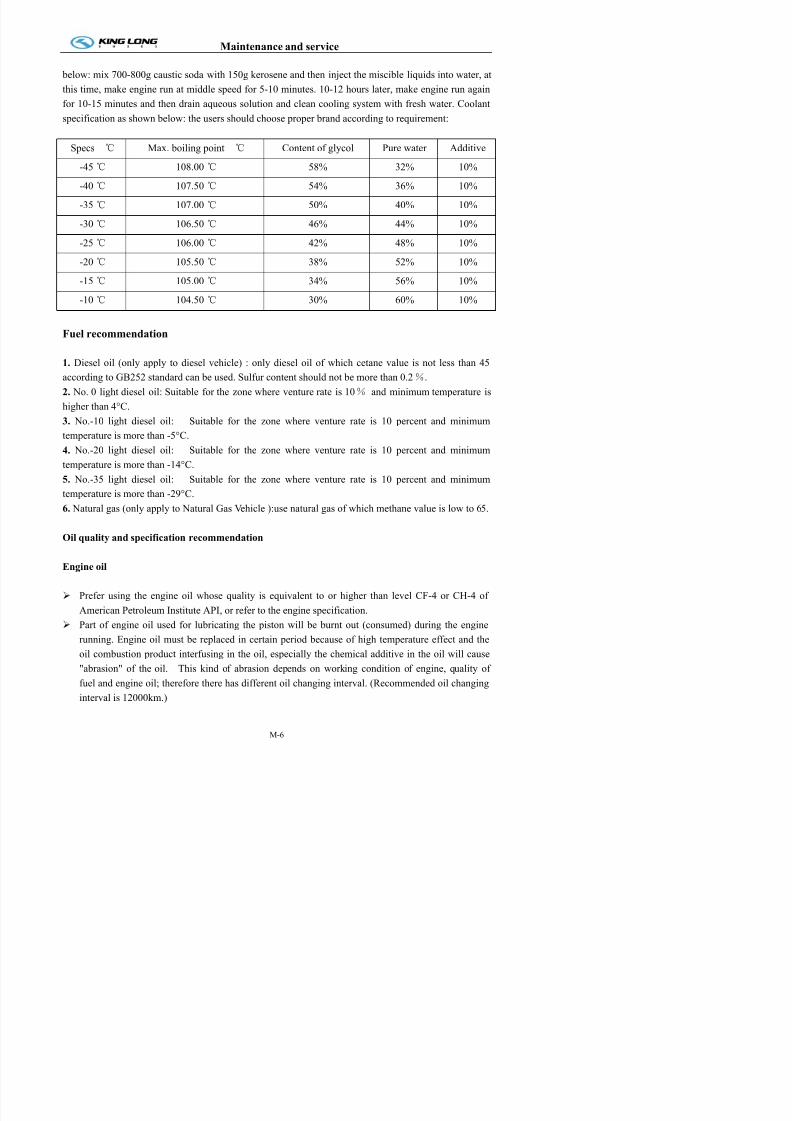
7/21/2019 Xmq6117y3 Operation Manual _philippines 4 2014 Eb100072 81
http://slidepdf.com/reader/full/xmq6117y3-operation-manual-philippines-4-2014-eb100072-81 92/144
specification as shown below: the users should choose proper brand according to requirement:
Specs ℃ Max. boiling point ℃ Content of glycol Pure water Additive
-45 ℃ 108.00 ℃ 58% 32% 10%
-40 ℃ 107.50 ℃ 54% 36% 10%
-35 ℃ 107.00 ℃ 50% 40% 10%
-30 ℃ 106.50 ℃ 46% 44% 10%
-25 ℃ 106.00 ℃ 42% 48% 10%
-20 ℃ 105.50 ℃ 38% 52% 10%
-15 ℃ 105.00 ℃ 34% 56% 10%
-10 ℃ 104.50 ℃ 30% 60% 10%
Fuel recommendation
1. Diesel oil (only apply to diesel vehicle) : only diesel oil of which cetane value is not less than 45
according to GB252 standard can be used. Sulfur content should not be more than 0.2%.
2. No. 0 light diesel oil: Suitable for the zone where venture rate is 10% and minimum temperature is
higher than 4°C.
3. No.-10 light diesel oil: Suitable for the zone where venture rate is 10 percent and minimum
temperature is more than -5°C.
4. No.-20 light diesel oil: Suitable for the zone where venture rate is 10 percent and minimum
temperature is more than -14°C.
5. No.-35 light diesel oil: Suitable for the zone where venture rate is 10 percent and minimum
temperature is more than -29°C.
6. Natural gas (only apply to Natural Gas Vehicle ):use natural gas of which methane value is low to 65.
Oil quality and specification recommendation
Maintenance and service
Engine oil viscosity
Since oil viscosity fluctuated with temperature, so the ambient temperature of engine working area
is very important to select viscosity grade (as shown in the figure). When temperature exceed lower
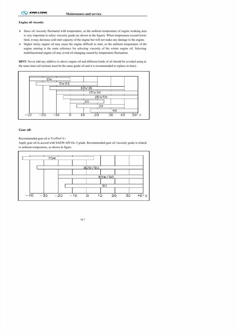
7/21/2019 Xmq6117y3 Operation Manual _philippines 4 2014 Eb100072 81
http://slidepdf.com/reader/full/xmq6117y3-operation-manual-philippines-4-2014-eb100072-81 93/144
y p y g ( g ) plimit, it may decrease cold start capacity of the engine but will not make any damage to the engine.
Higher sticky engine oil may cause the engine difficult to start, so the ambient temperature of the
engine starting is the main reference for selecting viscosity of the winter engine oil. Selecting
multifunctional engine oil may avoid oil changing caused by temperature fluctuation.
HINT: Never add any additive to above engine oil and different kinds of oil should be avoided using at
the same time (oil mixture must be the same grade oil and it is recommended to replace in time).
Gear oil:
Recommended gear oil is Ecofliud A+
Apply gear oil in accord with SAE90 API GL-5 grade. Recommended gear oil viscosity grade is related
to ambient temperature, as shown in figure.
Maintenance and service
Power steering hydraulic oil:
Fulfill standard: Generai Allison C-3. When ambient temperature is low than 10°C, please apply
DEXRON-II hydraulic fluid to steering gear; when ambient temperature is higher than 10°C, pleasel / h d li fl id / d il b d i ll ll /
7/21/2019 Xmq6117y3 Operation Manual _philippines 4 2014 Eb100072 81
http://slidepdf.com/reader/full/xmq6117y3-operation-manual-philippines-4-2014-eb100072-81 94/144
y g g p g papply C-3/10W hydraulic fluid. C-3/10W grade oil can be used in most area .all-year generally. C-3/30
grade oil can be used in non-cold area all-year generally.
Final drive lubricant:
Meet the using condition of GL-5(SAE90) grade heavy duty hyperboloid gear oil defined by API and
the ambient temperature requirement.
Clutch oil:
It is compound brake fluid (Laike 901) and must fulfill the standard GB10830-98JG3, GB12981
91H2Y3. It should be paid attention not to mix brake fluid with different types, otherwise it will affect
the using effect. The original brake fluid should be cleaned out before replacing the compound brake
fluid.
Chassis grease:
Grease added in each part should use 2# lithium base lubricant (suitable for temperature within
the range of -30~ +120℃).
Vehicle with centralized lubrication should use 0# lithium base lubricant.
Water tank coolant:
Long life anti-freezing and antirust fluid should be added to water tank. The coolant could be
general used both in winter and summer without adding and draining water in winter and it can prevent
forming scale and corroding cooling system. Freezing point of the coolant should be noticed to 5℃ lower than the lowest environment temperature. Different type of coolant should not be mixed using.
Replacing period of the coolant is 2 years.
Maintenance and service
Breaking-in of New Vehicle
Engine of new vehicle should be sure not to operate at the maximum power output during the
breaking-in period to keep best performance and superior efficiency as well as guarantee durable servicelif Pl d i ti l d tt ti t b l h d d i b ki i
7/21/2019 Xmq6117y3 Operation Manual _philippines 4 2014 Eb100072 81
http://slidepdf.com/reader/full/xmq6117y3-operation-manual-philippines-4-2014-eb100072-81 95/144
life. Please drive cautiously and pay more attention to abnormal phenomenon occurred during breaking-in
period. Given break-in mileage of the new vehicle is 2,500 km. keep under 100 km/h in breaking-in
period.
Preparation before breaking-in of the new vehicle
1. Wash the vehicle and check connection and tight situation of each place.
2. Check coolant storage in radiator and check each place of cooling system for leakage.
3. Check oil level of engine, clutch control system, transmission, drive axle, steering gear and clutch oil
storage tank. If deficient, add and then check each place for leakage.
4. Check and see if braking system works properly and leakage phenomenon exists at connections of all
valves and pipelines.
5. Check and see if phenomenon of loosing or clogging exists at each place of steering system.
6. Check and see if electric equipments, lamps and the instruments work properly and check battery
electrolyte level.
7. Check whether tire pressure has meet requirement.
8. Check and see if each transmission gear can engage properly.
Maintenance during breaking-in period
1. Running on smooth and good road surface.
2. Drive properly and engage the clutch smoothly. Gear shifting smoothly and impact is not allowed.
Neutral gear sliding is forbidden while engine stop. Emergency brake should occur as few as possible.
3. Speed limitation during breaking-in period: first gear ≤10km/h, second gear ≤20km/h, third
gear ≤30km/h, fourth gear ≤50km/h, fifth gear ≤60km/h, overspeed gear using can not be permitted during
breaking-in period .
4. Load limit: No load within 250km and never overload after 250km.5. Often pay attention to the temperature of transmission, drive axle, wheel hub and brake drum. If
overheating severely, find out causes and eliminate in time .
6 Pay more attention to keep the pressure of engine oil and the temperature of engine coolant within the
Maintenance and service
6. Check connection of transmission control mechanism for looseness.
7. Check connections of steering gear for looseness and damage.
8. Tighten bolts and nuts of front and rear suspension(carry out when full load)
9. Check connections of chassis and driving system according to specified torques. Tighten torques pleaserefer to corresponding instructions

7/21/2019 Xmq6117y3 Operation Manual _philippines 4 2014 Eb100072 81
http://slidepdf.com/reader/full/xmq6117y3-operation-manual-philippines-4-2014-eb100072-81 96/144
refer to corresponding instructions.
10. Check hydraulic system components of steering mechanism for fixing and tightness
11. Lubricate and maintain vehicle according to maintain items at 5,000km.
12. Check complete vehicle for oil, water and air leakage.
Maintenance and service
Daily or Refueling Maintenance Check
System Item Operation Technical requirement

7/21/2019 Xmq6117y3 Operation Manual _philippines 4 2014 Eb100072 81
http://slidepdf.com/reader/full/xmq6117y3-operation-manual-philippines-4-2014-eb100072-81 97/144
Engine
Air cleaner Check No leakage, damage, and crack.
Clips without looseness.
Fuel-water
separatorDrain
Release the water and fouling
Cooling fan InspectDo not pull or lever the cooling fan for starting the engine.
No crack, looseness, bend or damage.air inlet/ outlet
piping
Maintenance
check
Pipes without wear and damage, clips without looseness
prevent the air leakage.
Coolant level Check
Do not remove the water tank cover, unless the temperature i
less than 50℃, otherwise, it’s dangerous for operator
Do not add the cold coolant into the hot engine, unless th
engine temperature is less than 50℃
Engine oil level Check / correct
Do not start engine when oil level less than “L” or more tha
“H”.
Vehicle parking level, check the oil after engine stops for
minutes
Drive belt Check / correct No across crack, wear or material break off
Crankcase
breather tubeCheck
Check the breather tube in cold winter, cleanup the ic
blocking.
Engine and
AccessoriesCheck
No damage and crack
Clutch
Clutch pedal free
strokeCheck / adjust
Clutch release bearing clearance
Free stroke: 30~40 mm
Clutch system CheckCheck if clutch separated completely, connection stable an
not skidding
Clutch brake flui
levelCheck / add
Compound brake fluid
Brake chambe
Maintenance and service
Periodical maintenance and operation items and regulations
Periodical maintenance of each class: do maintenance during each interval or certain miles .
Special instruction: if assembly instruction requires different oil replace period, please follow the
instruction’s requirement on maintenance period and operation. If else please refer to this manual for

7/21/2019 Xmq6117y3 Operation Manual _philippines 4 2014 Eb100072 81
http://slidepdf.com/reader/full/xmq6117y3-operation-manual-philippines-4-2014-eb100072-81 98/144
maintenance requirement.
Maintenance operation and regulation every 2500km or 1 month
System Item Operation Technical requirement
Transmission
(ZF series)
Lubricant oil
surfaceCheck
Transmission lubricant oil surface within required
range, transmission each part and oil seal without
apparent leakage
Lubricant oil Change
The lubricant ZF-Ecofluid M 02E is
compulsory for initial fillings of transmissions as
well as fillings during transmission break-in(for
first 7500km only) Transmission fix
bolt
Fasten
Transmission air
hole
Check /
clean
Air hole smooth
Transmission and
Accessories
Check No leakage, operation organization effective, no
abnormal sound, wrong gear engagement.
Propeller shaft
Transmission shaftcross shaft flex
sleeve
Lubricate
Transmission shaft
bolt and nut
Check and
fasten
7.7-9m: T=180Nm
9m above:T=250-270Nm
Rear axle( ZF
series) Oil level Check TE-ML 12TE,1 time per month
Front axle(DF
Every greasenuzzle
Filling-up 2# lithium grease
Fastening piece Check &
adjust
Maintenance and service
System Item Operation Technical requirement
Rear axle(DF &
Check & fasten Rear axle housing and differential housing, rear
axle housing rear cover half axle bolts and nuts,
No loosen

7/21/2019 Xmq6117y3 Operation Manual _philippines 4 2014 Eb100072 81
http://slidepdf.com/reader/full/xmq6117y3-operation-manual-philippines-4-2014-eb100072-81 99/144
Maintenance operation and regulation every 5000km
FS series)
Fastening
piece
Check &
adjust
Ventilate
stopper
Clean
Front axle &
Rear axle
All wheel nuts Fasten Screw torque
7.7-9m: front 450 Nm rear 450 Nm9m above: DF: front 470 Nm, rear 490 Nm
Tire (include
spare Tire)
Check, air
charge, replace
Tire pressure: 0.67~ 0.75MPa,clean, no crack,
erosion or distortion, replace Tire if abraded too
much
System Item Operation Technical requirement
Steering system
Working condition Check Steering wheel max free rotation at middle
10 degrees
redirector auxiliary
oil and filter
element
Check Below 10℃ use DEXRON-II; above 10℃
use C-3/10W
Fix bolts of each place
Fasten Each fastening bolts not loosening, steeringarm not loosening, steering wheel swift,
Ball head LubricateEach turning ball head not loosening, no
clogging, clearance normal
ZF series Maintenance Free
GX85, GX 100, ZJ
100C
Change oil
and filter core
of oil tank
For first 5000km only, N32 which
manufactured by Shanghai oil refining
factory or ATF or related products which produced.
IPS seriesChange oil
and filter core
For first 5000km only, Environment
temperature >10℃, adopt CD level 15W/40
Maintenance and service
System Item Operation Technical requirement
Front axle
(DF & FSseries)
Brake clearance Check &
adjust

7/21/2019 Xmq6117y3 Operation Manual _philippines 4 2014 Eb100072 81
http://slidepdf.com/reader/full/xmq6117y3-operation-manual-philippines-4-2014-eb100072-81 100/144
Rear axle
(DF & FS
series)
Brake clearance Check &
adjust
Air
suspension
Fasteners Check/tighten Check and tighten the bolts, rods, height control
valves, air springs, shock absorbers, anti-roll bars.
The top covers of airsprings, height
control valves and the
joints of the air
course
Check Listening and wiping the liquid soap. If find any place is leaky, please either tighten the joints or
change the seal tape and clean the accumulated
water, oil in the piping and the dirt in the joints
Air
suspension
The exterior surface
of air springs
Check Find out the places which are abraded, distended,
bumped or cut
The air spring Change The surface of the air spring is damaged and
appears the cord fabric
The air spring Adjust/check If air spring interfere and knock with the
components around it, please adjust it in time.
The air spring
surface
Check/clean Clean the lubricant grease on the surface, the dirt
on the piston, the abnormal things placed between
the piston and air spring.
The air spring Check If there is leakage in the joints of the air springs
and the top cover, the air springs should be taken
apart, then check whether the edges of the air
springs and the top cover or the tapered sealing
zone are distorted. Change it if it is distorted.
The bumper Check It’s damage maybe the root damage of the tapered
sealing zoneThe height control
valve
Check If a height control valve controls two air springs
and one air springs is leaky, the other air springs
has not air too
Maintenance and service
System Item Operation Technical requirement
The brake pedal
free stroke
Check &
adjust
10-15mm
The braking
condition
Check Shoe drum clearance: 0.30mm ~ 0.50mm, in
complete braking pedal stroke not surpass 1/2 of the

7/21/2019 Xmq6117y3 Operation Manual _philippines 4 2014 Eb100072 81
http://slidepdf.com/reader/full/xmq6117y3-operation-manual-philippines-4-2014-eb100072-81 101/144
Brake
System
condition complete braking, pedal stroke not surpass 1/2 of the
whole stroke, check dry tin condition
The brake
pressure
Check Check whole vehicle brake pressure as required or
not. Above 0.6MPa
The brake nuts Inspect Inspect fastening of rear brake board’s nut
7.7-9 (m): 150-180 Nm,
9m above:front;160-205 Nm, rear:196-245 NmThe pipe and joint
sealing
Check Check brake pipe and joint sealing , No leakage
Chassis
Fastening body and
chassis connective
bolts, nuts
Check
The whole vehicle
body butter nozzleLubricate
Grease nozzle complete and effective, lubrication
good
Electrical
equipment
The whole
vehicle light and
instrument
Check
The battery fluid
surfaceCheck Add distilled water,
The wire joint
firmness, no rustCheck No rust
Air-con radiator
filtration netClean
Maintenance and service
Maintenance operation and regulation every 10000km or 3 months
Every 10000km include every 5000km maintenance operation
System Item Operation Technical requirement
Oil R l Ch k il f ithi i d

7/21/2019 Xmq6117y3 Operation Manual _philippines 4 2014 Eb100072 81
http://slidepdf.com/reader/full/xmq6117y3-operation-manual-philippines-4-2014-eb100072-81 102/144
Engine
Oil Replace Check oil surface within required range
Check engine and oil seal without apparent leakage
Replace oil when engine water temperature is 60 ,℃ for
removing the impurity
Oil level more than CF
Oil filter Replace Before installation add 1/2—3/4 to filter Air filter Check Clean air filter element
Air inlet/ outlet
system
Check No air leakage, no damage, each clip fastening good
Cooling system
and Intercooler
Check No leakage, each clip without damage or loosen
Water tank without leakage, damage, fouling
Coolant filter Replace Before re-install the coolant filter, daubs the 15W-40
lubricate oil on the interface of the sealing ring.
Fuel pump
installation
Check No leakage
Air compressor Check No air, oil, coolant leakage, lock nut and bolt no loosen or
damage
No carbon deposit
Brake system Check No leakage
Propeller shaft
fastening boltCheck
and fastenPropeller shaft flange fastening bolts not loosening
universal jointCheck
and fastenUniversal joint each bearing no loosening or damage
Front axle
(DF series)
Brake bottom
board
Check No loosening
Hub bear Check No looseningBrake plate Check /
change
Change the brake plate when plate abrasion more than
limit pit.
Brake bottom Check No loosening
Maintenance and service
Maintenance operation and regulation every 20000km or 5 months depend on what occurs first.
Every 20000km include every 10000km maintenance operation
System Item Operation Technical requirement

7/21/2019 Xmq6117y3 Operation Manual _philippines 4 2014 Eb100072 81
http://slidepdf.com/reader/full/xmq6117y3-operation-manual-philippines-4-2014-eb100072-81 103/144
Engine
Fuel filter Replace Replace fuel filter element accordingly
Steering hydraulic
oil
Replace Steering auxiliary oil surface within required range
Coolant system –
anti-freezing
Check Check the density of anti-freezing
Propeller shaft
Dust-proof cover Check Dust-proof cover without crack, damage, cli
reliable, bracket no loosening
Universal joint
condition
Check Universal joint without loosening, no bloc
abnormal sound
Propeller shaft
bracket
Check Propeller shaft bracket no loosening, screw torqu
120~140Nm
Middle bearing
clearance
Check Middle bearing clearance no more than 3mm
LubricateLubricate Lubricate each butter nozzle with 2# lithiu
lubricant grease
Steering system
GX85, GX 100, ZJ
100C
Change oil and
filter core of oil
tank
N32 which manufactured by Shanghai oi
refining factory or ATF or related products whic
produced.
IPS series25,35,40,55,65
Change oil and
filter core of oiltank
Environment temperature >10℃, adopt CD leve
15W/40 oil;Environment temperature <10℃, adopt No.
hydraulic drive fluid
Front axle Toe-in of front
wheelCheck & adjust Radial-ply tire: 0~+2mm
Rear axle(DF
& FS series)
Final drive Filling-up From injection hole into final drive filling
Parathion-type 90 heavy-duty gear oil (GL-5)
to the face.(for first 1500km, than change forevery 24,000km)
The leafCheck and
fasten weld
Not loosening, crack, fracture, misplacement,
screw U bolt front 196~294Nm rear 343~
Maintenance and service
System Item Operatio Technical requirement
The rubber balChange
There are gaps on the surface of the rubber
The surface of the rubber become adhesive, brittle and the rubbe
drop off seriously
The connection of the metal and the rubber is damaged The partia
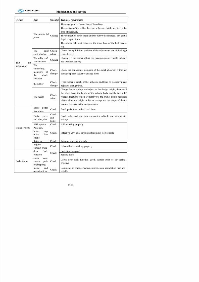
7/21/2019 Xmq6117y3 Operation Manual _philippines 4 2014 Eb100072 81
http://slidepdf.com/reader/full/xmq6117y3-operation-manual-philippines-4-2014-eb100072-81 104/144
The air
suspension
jointsChange The connection of the metal and the rubber is damaged. The partia
depth is up to 6mm
The rubber ball joint rotates in the inner hole of the ball head a
will
The heigh
control valve.
Check
adjust
Check the equilibrium position of the adjustment bar of the heigh
control valve.The rubber of
The link rodChange
Change it if the rubber of link rod becomes ageing, brittle, adhesiv
and lose its elasticity
The
connecting
members of
the shock
absorber
Check
change
Check the connecting members of the shock absorber if they ar
damaged please adjust or change them.
the rubberCheck
change
If the rubber is crack, brittle, adhesive and loses its elasticity pleas
adjust or change them.
The heightCheck
adjust
Charge the air springs and adjust to the design height, then chec
the wheel base, the height of the vehicle body and the two side’
wheels’ locations which are relative to the frame. If it is necessar
please adjust the height of the air springs and the length of the ro
in order to arrive to the design request
Brake system
Brake pedal
free strokeCheck Break pedal free stroke 12~15mm
Brake valve
and pipe joint
Check
and
fasten
Break valve and pipe joint connection reliable and without air
leakage
ABS system Check ABS working properly
Auxiliary brake, stop
brake free
stroke
Check Effective, 20% dual direction stopping at slop reliable
Maintenance and service
System Item Operation Technical requirement
front rear wind shield and
side window glass
Check ,
cleanClean, no crack, sealing good
body with paint Check Body paint no crack or peeling, re-paint color thesame as original

7/21/2019 Xmq6117y3 Operation Manual _philippines 4 2014 Eb100072 81
http://slidepdf.com/reader/full/xmq6117y3-operation-manual-philippines-4-2014-eb100072-81 105/144
Body, frame pattern, character, company
markCheck Pattern, character, company mark clear, complete
Body and frame Check
Function reliable, working properly, no distortion,
crack, fracture, welding split, connective bolts and
rivet fix firm and reliable
Inside
establishment
Driver seat CheckFix firm, front rear up down lock function reliableInstallation firm, backrest angle adjust lock
function reliable
Safety set Check
Safety belt function good, connection reliable, fire
extinguisher, urgency hammer complete and
effective
seat cover, carpet, curtain and
armrestCheck Clean, complete and firm
Compressor,
air reservoir,
safety valve
Compressor, air reservoir,
safety valve
Clean,
screw
Clean, connection reliable, no air leakage, safety
valve normal, pressure at 8Mpa, check air
reservoir, if with seeper, replace air drier filter
element
Electrical
equipment
Front lamp, horn, meters and
signal Check set complete and effective
Wiper generator Check Effective
Wiper connection rod Check,adjust
Reliable
Whole vehicle wiringCheck,
adjustcomplete, reliable, insulation good
Air-conditioner
Air-con passage and read
lamp control panel Check
Air-con passage installation reliable, functional
and effective
Air vent set Check Installation firm, working properly
Air-con strap tension andsurface condition
Check Tension proper, strap without crack, scuffing ordistortion
Magnetic clutch, fill lubricant Check Work properly, lubricant: 2# lithium grease
Air-con pipe Check No leakage or interference
Maintenance and service
Maintenance operation and regulation every 40000km or 8 months depend on what occurs first.
Every 40000km include every 20000km maintenance operation
System Item Operation Technical requirement
Drive belt Cooling fan belt tension Check/adjust Check each belt without loosening or damage
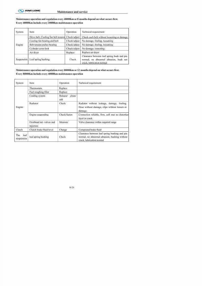
7/21/2019 Xmq6117y3 Operation Manual _philippines 4 2014 Eb100072 81
http://slidepdf.com/reader/full/xmq6117y3-operation-manual-philippines-4-2014-eb100072-81 106/144
Engine
Drive belt, Cooling fan belt tension Check/adjust Check each belt without loosening or damage
Cooling fan bearing and bolt Check/adjust No damage, fouling, loosening
Belt tension pulley bearing Check/adjust No damage, fouling, loosening
Cylinder cover bolt Check/adjust No damage, loosening
Air dryer Replace Replace air dryer
Suspension Leaf spring bushing CheckClearance between leaf spring bush and pinnormal, no abnormal abrasion, bush not
crack, lubrication normal
Maintenance operation and regulation every 80000km or 12 months depend on what occurs first.
Every 80000km include every 40000km maintenance operation
System Item Operation Technical requirement
Engine
Thermostats Replace
Fuel roughing filter Replace
Cooling system Release/ clean/
add
Radiator Check Radiator without leakage, damage, fouling.
Hose without damage, clips without loosen or
damage.
Engine suspending Check/fasten Connection reliable, firm, soft mat no distortion
layer or crack
Overhead set- valves and
injectors
Measure Valve clearance within required range
Clutch Clutch brake fluid level Charge Compound brake fluid The leaf
suspensionleaf spring bushing Check
Clearance between leaf spring bushing and pin
normal, no abnormal abrasion, bushing without
crack, lubrication normal
Maintenance and service
Maintenance operation and regulation more than 80000km
ZF Series axle
Oil or Grease change required, depending on what occurs first.

7/21/2019 Xmq6117y3 Operation Manual _philippines 4 2014 Eb100072 81
http://slidepdf.com/reader/full/xmq6117y3-operation-manual-philippines-4-2014-eb100072-81 107/144
Products
name
Model Maintenance content Maintenance
interval
Oil class Remark
Front
Axle
RL 85A
RL 85E
RL 55E
Filling-up
grease(lubricant point)
80,000-90,000KM or
1 year
NLGI Class 2
check-up oil level andchange oil regularly
every 20000KM
90,000~120,000KM2 years
TE-ML 02 for frontaxle head of
lubricant
only
lubricant grease of
shaft of wheel hub
change
Every 2 years TE-ML 12
Rear Axle
AV132
A80
A131
Oil change 150.000 km / 3 years TE-ML122RL
Rear Axle
A-132
(NewAV-132)
Oil change 150.000 km / 3 years TE-ML 12TE Old model
lubricant grease ofshaft of wheel hub
change ( include oil
seal)
250,000KM or 2years
RENOLITLX-PEP
2Rs36/04e
ZF parts No.: 0671
190 122
Wheel bearings with individual mounts at the
front and rear axles
500.000 km / 2 years
Compact bearings (hub unit) in the wheel
heads at the front and rear
axles
500.000 km / 4 years
Maintenance and service
Maintenance period chart
1、1st line is the item of break-in of new vehicle (prescript items completed after driving 2500KM or the day of
registration vehicle)
2、Other items are compulsion maintenance program (the circulation is 80000KM/12 months)
3、For engine、axle、transmission please refer to producer’s maintenance manual, if without special maintenance period, please refer to this manual for maintenance information.
4、“R” meaning: Replacement ; “I” meaning:Inspection & adjusting; “C” meaning:Cleaning

7/21/2019 Xmq6117y3 Operation Manual _philippines 4 2014 Eb100072 81
http://slidepdf.com/reader/full/xmq6117y3-operation-manual-philippines-4-2014-eb100072-81 108/144
4、 R meaning: Replacement ; I meaning:Inspection & adjusting; C meaning:Cleaning
Maintenanc
item
Maintenance period
*1000km 2.5 5 10 15 20 25 30 35 40 45 50 55 60 65 70 75 80
Month 1 3 5 7 8 9 10 11 12
Engine
Engine oil R I R I R I R I R I R I R I R I R
Oil filter R I R I R I R I R I R I R I R I R
Fuel filter element R I R I R I R I R I R I R I R I R
Air filter element C C C C C C R C C C C C R C C C C
Check& adjust belt I I I I I I I I I I I I I I I I I
Check & adjust
engine idle speedI I I I I I I I I I I I I I I I I
Fixing every bolt andconnection on engine
I I I I I I I I I I I I I I I I I
Checking seal of pipe& connector
I I I I I I I I I I I I I I I I I
Coolant I I I I I I I I I I I I I I I I R
Fuel system I I I I I I I I I I I I I I I I I
Oil & water separator I I I I I I I I I I I I I I I I I
Lubricating oil ingearbox of fan anglesteering gear
R I R I R I R I R
Air compressor, airreservoir & pipe
I&C I&C I&C I&C I&C
Radiator & expandwater tank
I I I I I
Fuel tank & oil pipe I I I I I
Fuel pump I I I I I
Water & oil separatorcore
I R R R R
Maintenance and service
Maintenance period chart
1、1st line is the item of break-in of new vehicle (prescript items completed after driving 2500KM or the day of
registration vehicle)
2、Other items are compulsion maintenance program (the circulation is 80000KM/12 months)
3、For engine、axle、transmission please refer to producer’s maintenance manual, if without special maintenance period, please refer to this manual for maintenance information.
4、“R” meaning: Replacement ; “I” meaning:Inspection & adjusting; “C” meaning:Cleaning

7/21/2019 Xmq6117y3 Operation Manual _philippines 4 2014 Eb100072 81
http://slidepdf.com/reader/full/xmq6117y3-operation-manual-philippines-4-2014-eb100072-81 109/144
g p ; g p j g; g g
Maintenanc
item
Maintenance period
*1000km 2.5 5 10 15 20 25 30 35 40 45 50 55 60 65 70 75 80
Month 1 3 5 7 8 9 10 11 12
Clutch
Release or meshing ifnot smoothly
I I I I I I I I I I I I I I I I I
Oil pipe system I I I I I I I I I I I I I I I I I
Clutch plate abrasion I I I I I I I I I I I I I I I I I
Free stroke of clutch pedal
I I I I I I I I I
Clutch oil I I I I I I I I R
Clutch cylinder &stroke
I I I I I I I I I
Transmission
Transmission if notleaking oil
I I I I I I I I I I I I I I I I I
Selector mechanism I I I I I I I I I I I I I I I I I
Lubricant oil R I I I R I I I R
Vent hole C I I I C I I I C I I I C I I I CPropeller shaft
Drive shaft connecting parts
I I I I I I I I I I I I I I I I I
Add lubricating oil indrive shaft
I I I I I I I I I I I I I I I I I
Universal joint cross& bearing
I I I I I I I I I
Fixing the bolt I I I I I I I I I
Middle bearing bracket & clearance
I I I I I
k
Maintenance and service
Maintenance period chart
1、1st line is the item of break-in of new vehicle (prescript items completed after driving 2500KM or the day of
registration vehicle)
2、Other items are compulsion maintenance program (the circulation is 80000KM/12 months)
3、For engine、axle、transmission please refer to producer’s maintenance manual, if without special maintenance period, please refer to this manual for maintenance information.
4、“R” meaning: Replacement ; “I” meaning:Inspection & adjusting; “C” meaning:Cleaning
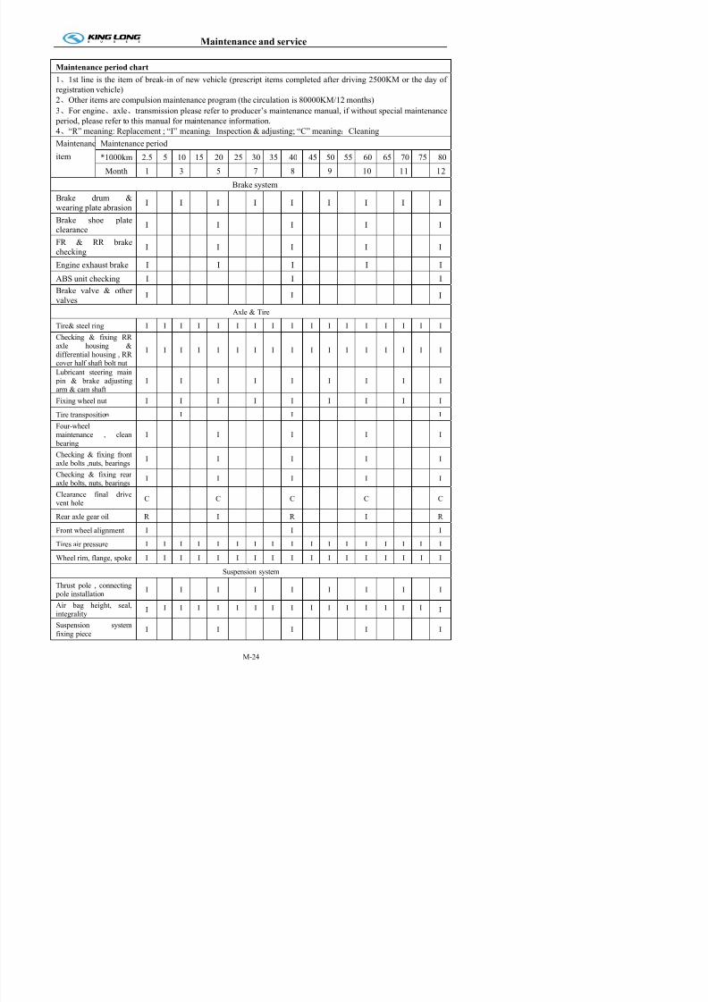
7/21/2019 Xmq6117y3 Operation Manual _philippines 4 2014 Eb100072 81
http://slidepdf.com/reader/full/xmq6117y3-operation-manual-philippines-4-2014-eb100072-81 110/144
Maintenanc
item
Maintenance period
*1000km 2.5 5 10 15 20 25 30 35 40 45 50 55 60 65 70 75 80
Month 1 3 5 7 8 9 10 11 12
Brake system
Brake drum &wearing plate abrasion
I I I I I I I I I
Brake shoe plateclearance
I I I I I
FR & RR brakechecking
I I I I I
Engine exhaust brake I I I I I
ABS unit checking I I I
Brake valve & other
valvesI I I
Axle & Tire
Tire& steel ring I I I I I I I I I I I I I I I I I
Checking & fixing RRaxle housing &
differential housing , RRcover half shaft bolt nut
I I I I I I I I I I I I I I I I I
Lubricant steering main pin & brake adjustingarm & cam shaft
I I I I I I I I I
Fixing wheel nut I I I I I I I I I
Tire transposition I I I
Four-wheelmaintenance , clean
bearing
I I I I I
Checking & fixing frontaxle bolts ,nuts, bearings I I I I I
Checking & fixing rear
axle bolts, nuts, bearingsI I I I I
Clearance final driveC C C C C
Maintenance and service
Maintenance period chart
1、1st line is the item of break-in of new vehicle (prescript items completed after driving 2500KM or the day of
registration vehicle)
2、Other items are compulsion maintenance program (the circulation is 80000KM/12 months)
3、For engine、axle、transmission please refer to producer’s maintenance manual, if without special maintenance period, please refer to this manual for maintenance information.
4、“R” meaning: Replacement ; “I” meaning:Inspection & adjusting; “C” meaning:Cleaning
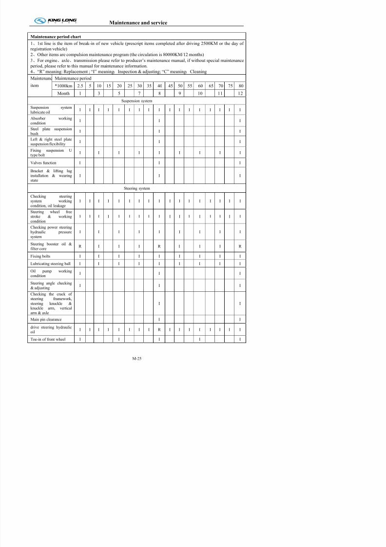
7/21/2019 Xmq6117y3 Operation Manual _philippines 4 2014 Eb100072 81
http://slidepdf.com/reader/full/xmq6117y3-operation-manual-philippines-4-2014-eb100072-81 111/144
Maintenanc
item
Maintenance period
*1000km 2.5 5 10 15 20 25 30 35 40 45 50 55 60 65 70 75 80
Month 1 3 5 7 8 9 10 11 12
Suspension system
Suspension systemlubricate oil
I I I I I I I I I I I I I I I I I
Absorber working
conditionI I I
Steel plate suspension bush
I I I
Left & right steel platesuspension flexibility
I I I
Fixing suspension U
type bolt
I I I I I I I I I
Valves function I I I
Bracket & lifting luginstallation & wearingstate
I I I
Steering system
Checking steeringsystem working
condition, oil leakage
I I I I I I I I I I I I I I I I I
Steering wheel freestroke & working
condition
I I I I I I I I I I I I I I I I I
Checking power steering
hydraulic pressuresystem
I I I I I I I I I
Steering booster oil &
filter coreR I I I R I I I R
Fixing bolts I I I I I I I I I
Lubricating steering ball I I I I I I I I I
Oil pump working
Common trouble and elimination
Maintenance period chart
1、1st line is the item of break-in of new vehicle (prescript items completed after driving 2500KM or the day of
registration vehicle)
2、Other items are compulsion maintenance program (the circulation is 80000KM/12 months)
3、For engine、axle、transmission please refer to producer’s maintenance manual, if without special maintenance period, please refer to this manual for maintenance information.
4、“R” meaning: Replacement ; “I” meaning:Inspection & adjusting; “C” meaning:Cleaning

7/21/2019 Xmq6117y3 Operation Manual _philippines 4 2014 Eb100072 81
http://slidepdf.com/reader/full/xmq6117y3-operation-manual-philippines-4-2014-eb100072-81 112/144
Maintenanc
item
Maintenance period
*1000km 2.5 5 10 15 20 25 30 35 40 45 50 55 60 65 70 75 80
Month 1 3 5 7 8 9 10 11 12
Electrical system
All lights I I I I I I I I I
Battery electrolyte
surface , connectorI I I I I I I I I
Wire box installation I I I I I I I I I I I I I I I I I
All wires , circuitry,connectors
I I I I I I I I I
A/C system & pre-heater system
Air conditioner system
refrigeration workingcondition
I I I I I I I I I
A/C compressor belt rate
of tensionI I I I I
A/C system pressure,compressor freeze oil
quantity
I I I I I
Autonomous water heat
system-fuel supplysystem
I I I I I
Autonomous water heat
system-water supplysystem
I I I I I
Vehicle body, framework
Luggage bin door airspring, stay bar
I I I I I
Engine bin door airspring, stay bar
I I I I I
Rearview mirror fixing I I I I I
V hi l b d
Common trouble and elimination
Engine common trouble and its elimination (suitable for diesel engine)
Diesel engine can not start
Possible causes Remedies

7/21/2019 Xmq6117y3 Operation Manual _philippines 4 2014 Eb100072 81
http://slidepdf.com/reader/full/xmq6117y3-operation-manual-philippines-4-2014-eb100072-81 113/144
Possible causes Remedies
1) Too low starting speed 1) Check the starting system and assure the starting speed is not
lower than 110rpm.
2) Air exists in the injection system 2) Check the looseness of the joints of the feed line. Unscrew
the de-aeration bolt on the fuel cleaner and oil water separator
assembly, then press fuel with hand priming pump until the fuel
overflows without air bubbles.
3) Fuel pipe clogged 3) Determine the location of the clog and clear it.
4) Fuel filter choked 4) Replace the screw-on filter element of the fuel filter/oil-water
separator assembly.5) Fuel supply pump does not apply
fuel or applies fuel irregularly
5) Check for leakage in the fuel inlet pipe
Clogging of the fuel supply pump filters and fix or replace.
6) Insufficient fuel injection, without
fuel injection or low injection pressure
6) Check the injector atomization situations and replace a new
one if it doesn’t work.
7) Starting system problems: 7) Check the connection to be correct and reliable.
Incorrect terminals connection or bad
contact;
Insufficient battery charge; Charge the battery.
Bad contact between the brush and
communicator of the starter
Repair or replace the brush and clean the surface of the
communicator with soft sand paper and blow off.
8) Insufficient compression pressure; 8) Replace the piston ring and press in the cylinder sleeve if
necessary.
Piston ring worn-out
9) The fuel cut off solenoid valve joint 9) Check the valve clearance valve spring valve stem and
Common trouble and elimination
Diesel engine power deficient
Possible causes Remedies
1)Intake blocked 1)Check the air cleaner, intake pipe, and clean or replace the air
cleaner filter elements

7/21/2019 Xmq6117y3 Operation Manual _philippines 4 2014 Eb100072 81
http://slidepdf.com/reader/full/xmq6117y3-operation-manual-philippines-4-2014-eb100072-81 114/144
cleaner filter elements.
2) high exhaust back pressure 2)Check the valve timing, adjust it if necessary; Clean the
exhaust pipe.
3 ) Insufficient boost pressure of
turbocharged system
3)Check and eliminate the leakage in the pipe and joints.
4) Turbocharger is out of order;
Compressor and turbine passages are
polluted, clogged or damaged;
4) Dean or replace the compressor casing and turbine housing.
Bearing failure; Replace it.
Carbon deposit and sludge in the
back of turbine and compressor
impellers.
Clean it.
5)middle cooler mangle ,leave out 5)Check and replace it.
6)Fuel line blocked or leaky 6)Check the seal of fuel line and fuel filter choking, or replace
screw-on filter element.
7)Poor atomization of injector 7)Check the inject pressure, remove carbon, adjust and repair8)Incorrect distribution phase 8)Check and adjust the distribution timing and valve lash
9)Cylinder gasket leakage 9)Tighten the cylinder head bolts according to the stated torque
and order, or replace the cylinder gasket.
10)Bad valve sealing 10)Grind or replace it.
11 ) Overheat engine or too high
coolant temperature
11)Check and repair the radiator, thermostat, and adjust fan belt
tension.
12)Piston ring worn-out or broken
13)Sensor doesn’t work
12)replace it
13)Check and replace it.
Common trouble and elimination
Abnormal noise during engine operation
Possible causes Remedies
1) Connecting rod bearing bushing andmain bearing bushing are worn-out
and clash voice appears in the
1) Dismantle and check the bushing and, if necessary, replace itand keep the reasonable clearance as required.

7/21/2019 Xmq6117y3 Operation Manual _philippines 4 2014 Eb100072 81
http://slidepdf.com/reader/full/xmq6117y3-operation-manual-philippines-4-2014-eb100072-81 115/144
pp
crankcase.
2) The Damper is damaged and
invalid.
2) Change components to keep regulated axial clearance
3) The shock absorber is damaged and
ineffective
3) Check and see if the joint bolts are in good conditions, and
change new ones if necessary.
4) The valve knocks on the piston4) Check and adjust the valve timing.
5) The driving gear is abrased and get
too large gap. There is knocking
sound at the timing gear box cover.
5) Check the gear side clearance and change the gear or not
according to the abrasion situations.
6) Too big clearance between piston and
cylinder and there is knocking sound
at the cylinder wall.
6) Change the piston and use the repairing cylinder liner. Keep the
proper clearance between piston and cylinder.
7) Puff vibration of supercharger7) Remove the carbon and waste in the compressor channel and
the exhaust channel.
8) The bearing of supercharger is
damaged and the rotor knocks on the
shell
8) Change the supercharger assembly
9) The valve clearance is too large and
there is big noise at the cylinder head.9) Adjust the valve clearance.
Common trouble and elimination
Exhaust with black smoke
Possible causes Remedies
1) Intake clogged 1) heck and clean the air cleaner and intake passage.
2) Poor fuel quality 2) Use prescribed fuel.

7/21/2019 Xmq6117y3 Operation Manual _philippines 4 2014 Eb100072 81
http://slidepdf.com/reader/full/xmq6117y3-operation-manual-philippines-4-2014-eb100072-81 116/144
) q y ) p
3) Incorrect distribution timing 3) Adjust the distribution timing according to the instruction.
4) Bad atomization of injector 4) Check and repair or replace
5) The injector spray too much fuel 5) Check and adjust it accordion to the instruction.
6) Check and repair or replace 6) Check and repair leak in the pipe line and joints.
7) Faulty turbocharger 7) Check and replace the assembly.
8) middle cooler damaged and leaked 8) Repair or replace it
Exhaust with white and blue smoke
Possible causes Remedies
1) Poor quality fuel and too much water
in fuel
1) Replace the fuel.
2) Too low coolant temperature 2) Check the working temperature of the thermostat,
replace it if necessary.
3) Incorrect distribution 3) Check and adjust it.
4) Too low Pressure 4) Check the working temperature of the thermostat,
replace it if necessary.
5) Incorrect installing orientation of piston
rings
5) Check and reinstall correctly.
Common trouble and elimination
Too low oil pressure
Possible causes Remedies
1) Diluted or incorrectly selected 1) Select the proper oil.
2) Inner and outer rotors of oil pump worn-out 2) Replace the oil pump.

7/21/2019 Xmq6117y3 Operation Manual _philippines 4 2014 Eb100072 81
http://slidepdf.com/reader/full/xmq6117y3-operation-manual-philippines-4-2014-eb100072-81 117/144
or too large
3) Oil filter choked 3) Replace the whirling type filter element.
4) Failure of oil filter pressure control 4) Repair it.
5) Gear of oil pump damage 5) Replace it.
6) Inlet oil tube of fuel pump crack 6) Repair or replace it.
7) Fixing bolt of oil pump inlet oil tube loose 7) Tighten the bolt to the required torque.
8) Too large bearing bushings clearance. 8) Check and replace it.
Too high oil pressure
Possible causes Remedies
1) Too low ambient temperature and too
high oil viscosity
1) Use the required grade engine oil. Operate at low speed
after starting, and then check it when the oil temperature is
normal.2) Over-flow valve clogged 2) Check and clean it
Too high oil temperature and oil consumption
Possible causes Remedies
1) Leakage in the exterior oil line 1) Check and repair it.
2) Too high diesel engine load 2) Decrease the load.
Common trouble and elimination
Chassis constant fault and elimination
Clutch
Faultsymptom
Possible cause Eliminating method
1.The noise occurs when the clutch

7/21/2019 Xmq6117y3 Operation Manual _philippines 4 2014 Eb100072 81
http://slidepdf.com/reader/full/xmq6117y3-operation-manual-philippines-4-2014-eb100072-81 118/144
Abnormal
sound of theclutch
disengages
1) Flywheel support bearing stuck
2) Release bearing stuck
2. The noise occurs when the clutch
engages
1) Clutch driven disk worn
2) Clutch torsion damping spring
broken
3) Transmission bearing or gear broken
1) Replace the bearing
2) Replace the bearing
1) Replace the clutch driven disc
2) Replace the clutch driven disc
3) Replace the bearing or the gear
Clutch does
not
disengage
smoothly or
can not
disengage
1. When operational travel of the clutch
pedal is correct1) Uneven or deformity of the clutch
pressure plate or the flywheel and
the driven disc
2) Abrasion or clogging of the clutch
plate spline
3) Cllogging of the flywheel supporting bearing
4) Pressure spring distorted
5) Impurity in the clutch plate, the
pressure plate and the flywheel
6) Distortion or breakdown of the
diaphragm spring
2. The clutch pedal is in normal
operation but the pedal travel is too
large
1) Correct or replace faulted parts.
2) Repair or replace the clutch plate and
lubricate the moving region by
anti-high temperature grease
3) Replace the bearing
4) Replace the pressure spring
5) Remove and wash.
6) Check the distortion or the breakdown
and change the faulted parts
1) Adjust the travel to the given range
Common trouble and elimination
Fault
symptomPossible cause Eliminating method
4. No braking fluid in the clutch oil
tank
1) Leakage
2) There has leakage during the
hydraulic cylinder operation
1) Check and repair leakage or replace
faulted components.
2) Disassemble and repair.
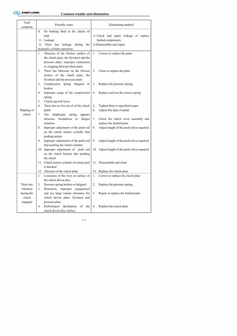
7/21/2019 Xmq6117y3 Operation Manual _philippines 4 2014 Eb100072 81
http://slidepdf.com/reader/full/xmq6117y3-operation-manual-philippines-4-2014-eb100072-81 119/144
hydraulic cylinder operation
Slipping of
clutch
1. Abrasion of the friction surface of
the clutch plate, the flywheel and the
pressure plate; improper connection
or clogging between these parts2. There has lubricant on the friction
surface of the clutch plate, the
flywheel and the pressure plate
3. Compression spring fatigued or
broken
4. Improper usage of the compression
spring
5. Clutch cap bolt loose
6. There has no free travel of the clutch
pedal
7. The diaphragm spring appears
abrasion, breakdown or fatigue
situation
8. Improper adjustment of the push rod
on the clutch master cylinder that
pushing piston
9. Improper adjustment of the push rod
that pushing the clutch cylinder
10. Improper adjustment of push rod
on the clutch booster that pushingthe clutch
11. Clutch master cylinder oil return port
is blocked
1. Correct or replace the parts
2. Clean or replace the parts
3. Replace the pressure spring
4. Replace and use the correct spring
5. Tighten blots to specified torque
6. Adjust free play of pedal.
7. Check the clutch cover assembly and
replace the faulted parts
8. Adjust length of the push rod as required
9. Adjust length of the push rod as required
10. Adjust length of the push rod as required
11. Disassemble and clean
Common trouble and elimination
Fault
symptomPossible cause Eliminating method
There has
vibration
during the
clutch
engaged
5. Driven plate damping spring broken
6. Uneven height of the clutch lever
7. Performance declination or
breakdown of the diaphragm spring
5. Replace the clutch plate
6. Adjust the height of each release lever
7. Check the clutch cover assembly and
replace the faulted parts
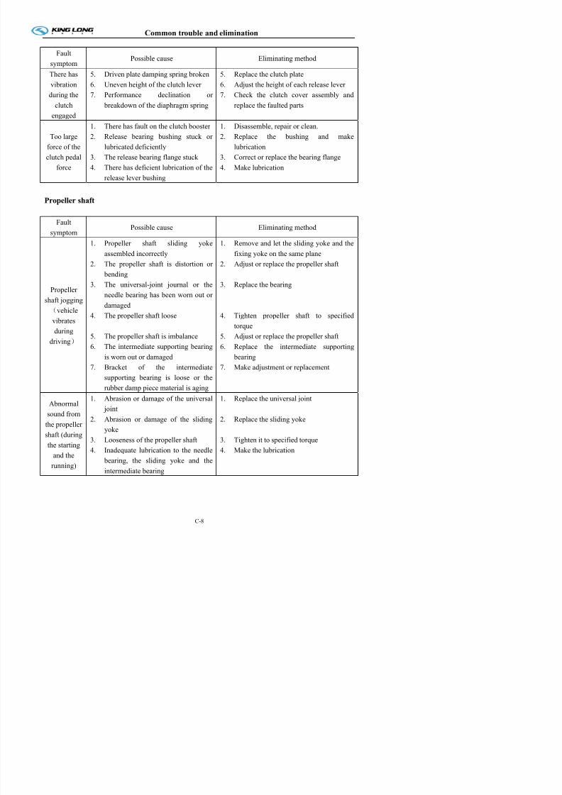
7/21/2019 Xmq6117y3 Operation Manual _philippines 4 2014 Eb100072 81
http://slidepdf.com/reader/full/xmq6117y3-operation-manual-philippines-4-2014-eb100072-81 120/144
engaged
Too large
force of the
clutch pedalforce
1. There has fault on the clutch booster
2. Release bearing bushing stuck or
lubricated deficiently
3. The release bearing flange stuck4. There has deficient lubrication of the
release lever bushing
1. Disassemble, repair or clean.
2. Replace the bushing and make
lubrication
3. Correct or replace the bearing flange4. Make lubrication
Propeller shaft
Fault
symptom Possible cause Eliminating method
Propeller
shaft jogging
(vehicle
vibrates
during
driving)
1. Propeller shaft sliding yoke
assembled incorrectly
2. The propeller shaft is distortion or
bending
3. The universal-joint journal or the
needle bearing has been worn out ordamaged
4. The propeller shaft loose
5. The propeller shaft is imbalance
6. The intermediate supporting bearing
is worn out or damaged
7. Bracket of the intermediate
supporting bearing is loose or the
rubber damp piece material is aging
1. Remove and let the sliding yoke and the
fixing yoke on the same plane
2. Adjust or replace the propeller shaft
3. Replace the bearing
4. Tighten propeller shaft to specified
torque
5. Adjust or replace the propeller shaft
6. Replace the intermediate supporting
bearing
7. Make adjustment or replacement
Common trouble and elimination
Transmission
Fault
symptomPossible cause Eliminating method
1. Control mechanism1) Improper height of the control hinge
2) There has clearance between the
l hi i
1) Adjust the control hinge
2) Correct or replace the parts

7/21/2019 Xmq6117y3 Operation Manual _philippines 4 2014 Eb100072 81
http://slidepdf.com/reader/full/xmq6117y3-operation-manual-philippines-4-2014-eb100072-81 121/144
Difficult
gear shift(Difficult
gear
engagement)
control hinge connection
3) The control hinge bend
2. Transmission
1) Abrasion or damage of the bearing
2) Synchronizer operates abnormally
3) The shaft or the gear is wore or
damaged
4) Abnormal slip of the gear shifter
shaft
3. Others
1) Clutch can not disengage normally
2) The lubrication viscosity is too high
3) Correct or replace the control hinge
1) Replace the bearing
2) Correct or replace the parts
3) Correct or replace the parts
4) Correct
1)
See " Clutch does not disengagesmoothly or can not disengage "
2) Use the lubrication of given grade
The
transmission
gear is off
the engaging
position
Transmission
1) Shift fork distorted or worn
2) Abrasion of lthe lockup ball or the
ball on the gear shifter shaft
3) Breakdown or fatigue of the lock
spring
4) Excessive clearance of the gear
engagement
5) Excessive clearance along the
gearing axial direction
6) Abrasion of the sliding bearing
slipper or its end surface
1) Check the gear-shifter fork and make
adjustment or replacement in case of
bending
2) Disassemble and replace the worn-out parts
3) Replace the spring
4) Adjust the gear clearance or replace the
gear
5) Measure the axial clearance and replace
the thrust washer if necessary
6) Replace the bushing
Common trouble and elimination
Rear axle
Fault
symptom
Possible cause Eliminating method
When the vehicle is starting
1) Excessive clearance between
the differential gear
1) Adjust the clearance
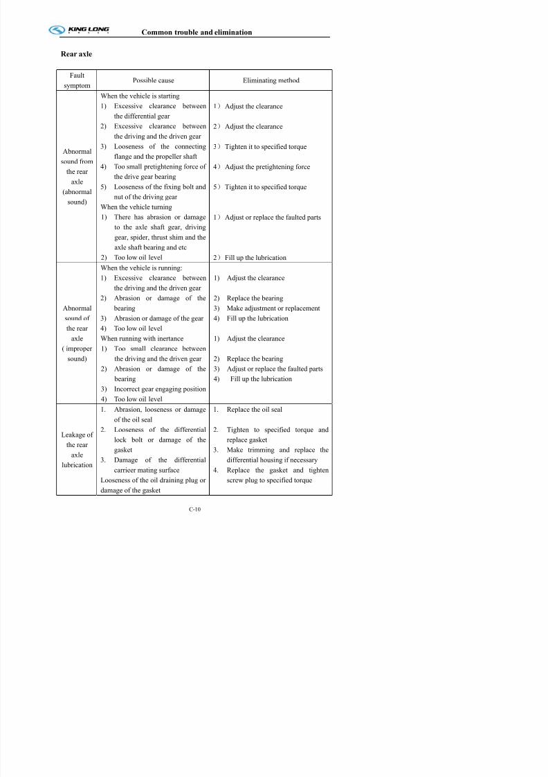
7/21/2019 Xmq6117y3 Operation Manual _philippines 4 2014 Eb100072 81
http://slidepdf.com/reader/full/xmq6117y3-operation-manual-philippines-4-2014-eb100072-81 122/144
Abnormal
sound from
the rear
axle
(abnormal
sound)
the differential gear
2) Excessive clearance between
the driving and the driven gear
3) Looseness of the connecting
flange and the propeller shaft
4) Too small pretightening force of
the drive gear bearing
5) Looseness of the fixing bolt and
nut of the driving gear
When the vehicle turning
1) There has abrasion or damage
to the axle shaft gear, driving
gear, spider, thrust shim and the
axle shaft bearing and etc
2) Too low oil level
2) Adjust the clearance
3) Tighten it to specified torque
4) Adjust the pretightening force
5) Tighten it to specified torque
1) Adjust or replace the faulted parts
2) Fill up the lubrication
Abnormal
sound of
the rear
axle
( improper
sound)
When the vehicle is running:
1) Excessive clearance between
the driving and the driven gear2) Abrasion or damage of the
bearing
3) Abrasion or damage of the gear
4) Too low oil level
When running with inertance
1) Too small clearance between
the driving and the driven gear2) Abrasion or damage of the
bearing
1) Adjust the clearance
2) Replace the bearing
3) Make adjustment or replacement
4) Fill up the lubrication
1) Adjust the clearance
2) Replace the bearing3) Adjust or replace the faulted parts
4) Fill up the lubrication
Common trouble and elimination
Fault
symptomPossible cause Eliminating method
Leakage of
4. Blocking or damage of the
ventilation plug
5. Axle housing cracks
6. Damageor distortion of the
5. Clean or replace the ventilation
plug
6. Repair or replace the axle housing
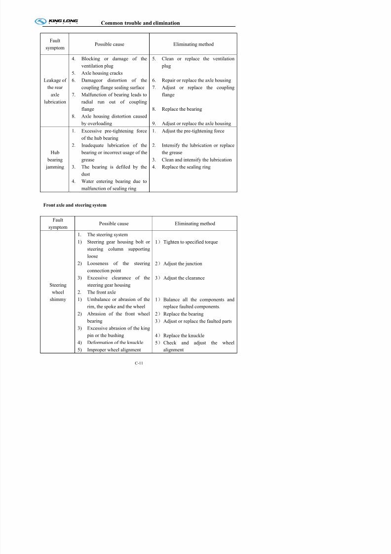
7/21/2019 Xmq6117y3 Operation Manual _philippines 4 2014 Eb100072 81
http://slidepdf.com/reader/full/xmq6117y3-operation-manual-philippines-4-2014-eb100072-81 123/144
the rear
axle
lubrication
coupling flange sealing surface
7. Malfunction of bearing leads to
radial run out of coupling
flange8. Axle housing distortion caused
by overloading
7. Adjust or replace the coupling
flange
8. Replace the bearing
9. Adjust or replace the axle housing
Hub
bearing jamming
1. Excessive pre-tightening force
of the hub bearing
2. Inadequate lubrication of the
bearing or incorrect usage of the
grease3. The bearing is defiled by the
dust
4. Water entering bearing due to
malfunction of sealing ring
1. Adjust the pre-tightening force
2. Intensify the lubrication or replace
the grease
3. Clean and intensify the lubrication4. Replace the sealing ring
Front axle and steering system
Fault
symptomPossible cause Eliminating method
1. The steering system
1) Steering gear housing bolt or
steering column supporting
loose2) Looseness of the steering
connection point
1) Tighten to specified torque
2) Adjust the junction
Common trouble and elimination
Fault
symptomPossible cause Eliminating method
6) Fatigue of the front leaf spring,
looseness of the "U" -bolt or
damage of the central bolt
6) Replace the faulted parts
1. The steering system
1) Difficulty in the gear 1) Adjust the gear engagement

7/21/2019 Xmq6117y3 Operation Manual _philippines 4 2014 Eb100072 81
http://slidepdf.com/reader/full/xmq6117y3-operation-manual-philippines-4-2014-eb100072-81 124/144
Failure of
steering
wheel return
to center
engagement
2) Malfunction of power steering
system
3) Improper contact with the power piston
4) Fatigue of the return spring
5) Malfunction of slide valve
2. The front axle
1) Excessive caster angle of the
king pin
2) Overhaul and eliminate trouble
3) Adjust or replace the power piston
4) Replace the spring
5) Check diameter of the slide valve
and the housing and replace them
if necessary
1) Check and adjust the front wheel
alignment
Disalignment
of the steeringwheel
1. The alignment of front wheel
incorrect
2. There has fatigue and damage
in the front plate spring
3. Bending of the front axle
4. Unsmooth of the braking
5. Looseness of the front hub
bearing nut
6. Inequality of the tire pressure
7. Tires with different dimension
applied
1. Check and adjust the front wheel
alignment
2. Replace the faulted spring
3. Adjust or replace the front axle
4. Please refer to the chapter
"braking"
5. Tighten to specified torque
6. Inflate to the given pressure
7. Replace the tire by the correct
type
1. The front axle1) Incorrectness of the wheel
alignment
2) Ab i k f th
1) Check and adjust the front wheel
alignment
2)R l th b i ti ht t
Common trouble and elimination
Fault
symptomPossible cause Eliminating method
Misproportion
or untimely
tire wear
3. Others
1) Breakdown caused by the
abrupt starting or the emergent
braking
2) Overloading
1) Correct the driving pattern
2) Make the loading according to the
specified capacity

7/21/2019 Xmq6117y3 Operation Manual _philippines 4 2014 Eb100072 81
http://slidepdf.com/reader/full/xmq6117y3-operation-manual-philippines-4-2014-eb100072-81 125/144
Heavy
operation of
the steering
wheel (the
steering
system
breakdown)
1. Too low oil level
2. Lubricant deterioration or
impurity in it
3. Abrasion of the steering junction
4. Fault of the power steering
system
5. Excessive lubricant resistance
caused by the pipeline sunken
6. Too low oil pressure caused
by the ineffective hydraulic
pump
7. There has air in the hydraulic
pipeline
8. Malfunction of rotary valve
9. Abrasion or damage of the
power cylinder and damage of
the piston O -ring
10. Too much leakage of the oil
inside the steering gear
housing
1. Add the lubricant to the given
level
2. Replace the lubricant
3. Replace the ball stud
4. Overhaul and eliminate trouble.
5. Measure the backpressure and
repair or replace the pipeline in
case of the set value exceeded
6. Measure the oil pressure and theflow volume; disassemble and
repair the hydraulic pump if the
set value belowed
7. Bleed air and add oil.
8. Disassemble and repair rotary
valve.
9. Disassemble and repair.
10. Disassmeble and repair steering
housing.
1. Improper adjustment of the
wheel alignment (excessive
t l )
1. Check and adjust the wheel
alignment
Common trouble and elimination
There has oil
spillage in the
steering oil
tank
1. Clogging of the strainer or the
filter element
2. There has air in the pipeline
1. Clean the filter strainer or replace
the filter element
2. Add the oil and make the
exhaustion
Braking system

7/21/2019 Xmq6117y3 Operation Manual _philippines 4 2014 Eb100072 81
http://slidepdf.com/reader/full/xmq6117y3-operation-manual-philippines-4-2014-eb100072-81 126/144
Fault
symptomPossible cause Eliminating method
Unsmooth
of the
wheel
1. There has compressed air inside
the braking chamber
2. Improper lubrication of the
camshaft or improper return of
the adjusting arm
3. Brake shoe or chamber return
spring fatigued or broken
4. The spring braking takes effect
5. Clogging of the exhaust port in
the quick release valve
6. Brake valve primary or
secondary piston return failure
1. Check and adjust the exhaust valve
of the quick releasing valve
2. Adjust the faulted parts
3. Replace the faulted parts
4. Eliminate causes of the spring
braking unreleased
5. Disassemble and clean the faulted
parts
6. Disassemble and clean the braking
valve and replace the faulted parts
as needed
There has
abnormal
sound
when
troddening
1. The clincher or the bolt is projected because of abrasion of
the braking friction lining
2. Surface hardening of the
friction lining
3. Deterioration of the friction
lining
4. Improperly contact between the brake shoe and the friction
lining
1. Replace the friction lining
2. Replace the friction lining
3. Replace the friction lining
4. Rivet the rivet or tighten bolt
5. Adjust or tighten the brake drum
Common trouble and elimination
Fault
symptomPossible cause Eliminating method
1. Tire pressure uneven or tire
dimension different
2. Improper installation of the
brake shoe or damage of the
return spring
3 I t f th
1. Operate as required
2. Tighten the locknut of the brake
shoe supporting pin and replace the
return spring
3 Adj t th f i ti li i

7/21/2019 Xmq6117y3 Operation Manual _philippines 4 2014 Eb100072 81
http://slidepdf.com/reader/full/xmq6117y3-operation-manual-philippines-4-2014-eb100072-81 127/144
Unsteady
braking
3. Improper engagement of the
braking friction lining
4. Improper adjustment of the left
and right brake5. Deterioration of the braking
friction lining
6. Oil on the braking friction
lining
7. Damage of the brake backing plate
8. Looseness of the leaf spring
U-bolt
3. Adjust the friction lining
4. Adjust the brake
5. Replace the friction lining
6. Clean with the gasoline to
eliminate the effect of the leakage
at the hub oil seal, oil cylinder
cover and the rubber cap
7. Replace it8. Tighten the U-bolt
The
braking
can't be
applied
under all
When compressed air pressure is
normal:
1. Too short of the brake valve
travel
2. The camshaft doesn't rotate (the
bushing is lack of lubricant)
3. Improper adjustment of the
braking chamber pusher stroke
4. Improper sliding contact of the
relay valve
5. Overheat or deterioration of the
braking friction lining
6 Improper engagement of the
1. Check ,and replace the braking
valve if necessary
2. Check working condition of the
camshaft and replace it as needed
3. Adjust the travel
4. Disassemble and repair
5. Replace the friction lining
6 Adjust engagement position of the
Common trouble and elimination
Fault
symptomPossible cause Eliminating method
When compressed air pressure is
abnormal:
1. There has air leakage inside the
air pipeline
2. The air compressor doesn't
work
1. Repair the leakage point
2. Disassemble and repair air
compressor
3 Adjust or wash

7/21/2019 Xmq6117y3 Operation Manual _philippines 4 2014 Eb100072 81
http://slidepdf.com/reader/full/xmq6117y3-operation-manual-philippines-4-2014-eb100072-81 128/144
work
3. The pressure regulator is
improper adjusted or failured
because of the impurity enteringAir leakage in the brake valve
3. Adjust or wash
4. Disassemble and repair the brake
valve
Common trouble and troubleshooting of electrical equipment and starting
system
Fault
symptom Possible cause Eliminating method
There has
abnormal
sound
during the
generator
rotates
1. The belt is of over loose or
excessive abrasion with the
shaking during the running
2. Bearing failure or oversize
clearance
3. Too much bearing clearance
Adjust the belt and replace the bearing
The
charging
indicator
light
doesn't go
off during
the running
and the
vehicle is
1. The battery is lack of power
2. The generator is damaged
3. Charging indicator lamp loop
short
4. The belt is slipping
1. Charge the battery
2. Replace the generator
3. Check the circuit
4. Adjust the belt
Common trouble and elimination
Fault
symptomPossible cause Eliminating method
1. The battery has no power, or is
lack of power or terminal loose
2. Poor contact of the starter
switch, short circuit of the
connector lug or bad of the
solenoid
1. Charge and clean the joint and
screw it
2. Repair or replace it

7/21/2019 Xmq6117y3 Operation Manual _philippines 4 2014 Eb100072 81
http://slidepdf.com/reader/full/xmq6117y3-operation-manual-philippines-4-2014-eb100072-81 129/144
Difficult in
starting
solenoid
3. Starter pinion is clogged in the
flywheel ring gear.
Furthermore, engine bearing is burnt ,water on external of the
combustion chamber and the
consumption frozen may also
caused the breakdown
3. Repair or replace it
Found out the reason and eliminate it
Startinggear of the
starter can
not engage
with the
flywheel
teeth
1. Poor contact of the ignition
switch or socket loose
2. Unsteady connection of therelay device or the solenoid
switch
3. Turnoff of the starter solenoid
switch
4. Damage of the starting gear or
the gear ring of starter
5. Malfunction of engage switch
6. Starter armature shaft bent
1. Clean and tighten
2. tighten it
3. Replace it
4. Repair the teeth or replace it
5. Found out the reason and eliminate
it
6. Replace it
Starting
gear of the
starter can
not
disengage
l t l
1. Starter starting gear sleeve too
tight or stuck
2. Too little clearance between the
starting gear and the flywheel
ring gear or the starter gear
damage
3. Magnetic coil dirty
4 Cl i f th t i i
1. Replace the shaft sleeve or clean
and amend it
2. Adjust the clearance or replace the
starting gear
3. Clean it
4. Clean and adjust it
Common trouble and elimination
Common trouble and troubleshooting of air conditioner system
The remedy and trouble analysis under abnormal pressure
No. Pressure Description Analysis Remedy
The high and low
There is bubble in the
inspection glass ; the
cold air in the bus
insufficient ; high
pressure pipe a little bit
The refrigerant
filling is not
Check the
system for the
leakage and find
out the leaking
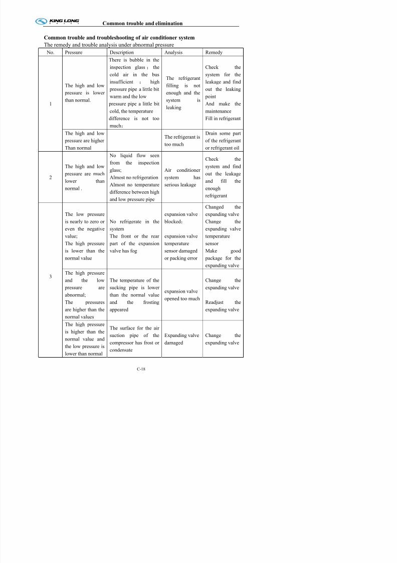
7/21/2019 Xmq6117y3 Operation Manual _philippines 4 2014 Eb100072 81
http://slidepdf.com/reader/full/xmq6117y3-operation-manual-philippines-4-2014-eb100072-81 130/144
1
pressure is lower
than normal.
pressure pipe a little bit
warm and the low
pressure pipe a little bit
cold, the temperaturedifference is not too
much;
enough and the
system is
leaking
out the leaking
point
And make the
maintenanceFill in refrigerant
The high and low
pressure are higher
Than normal
The refrigerant is
too much
Drain some part
of the refrigerant
or refrigerant oil
2
The high and low
pressure are much
lower than
normal .
No liquid flow seen
from the inspectionglass;
Almost no refrigeration
Almost no temperature
difference between high
and low pressure pipe
Air conditioner
system has
serious leakage
Check the
system and find
out the leakage
and fill the
enough
refrigerant
3
The low pressure
is nearly to zero or
even the negative
value;
The high pressure
is lower than the
normal value
No refrigerate in the
system
The front or the rear
part of the expansion
valve has fog
expansion valve
blocked;
expansion valve
temperature
sensor damaged
or packing error
Changed the
expanding valve
Change the
expanding valve
temperature
sensor
Make good
package for theexpanding valve
The high pressure
d th l Th t t f th Ch th
Common trouble and elimination
No. Pressure Description Analysis Remedy
4
The high and low
pressure aremuch higher than
the normal value
and the needle of
h i
The cooling capability
is
Insufficient and the
system has air and the
bubbles seen in the
Air mixed in the
refrigerant The
vacuum is not
good for the first
time filling
refrigerant or
Discharge the
refrigerant in
the system
and change
the desiccators
and also make
the vacuum

7/21/2019 Xmq6117y3 Operation Manual _philippines 4 2014 Eb100072 81
http://slidepdf.com/reader/full/xmq6117y3-operation-manual-philippines-4-2014-eb100072-81 131/144
the gauge swing
obviouslyinspection glass
g
after the
maintenance
repeatedly for
filling the
refrigerant
5
The high
pressure is
higher than the
normal value and
the low pressure
is nearly to zero
or negative valueand the gauge
swing seriously
The air sent to the
bus sometime cold
and sometimes
warm and the
inspection glass
looks yellow
Too much water
in the system
desiccators
reaching the
saturation
the frosting
water blockedthe
expanding valve
Change the
desiccators and
make the
vacuum
repeatedly and
then re-fill therefrigerant
6
The low pressure
is much higher
than the normal
value and the
high pressure is
a little bit higher
than the normal
value
Cold is in sufficient
The condenser
blower doesn’t
work normally
or there is blockage in the
condenser
radiator
Check the
electric circuit
diagram orcleaning the
condenser
7
The high are low
and low
pressure are
higher than the
normal values
The cold air is
insufficient
Compressor
interior failure
Repair or change
the compressor
E t
Common trouble and elimination
Electric system trouble and remedy
Fault
symptomPossible cause Eliminating method
the power
lamp on the
control
panel not
light
1. + no power supply;
2. D+ not connected well;
3. harness not tight;
4. control unit failure;
1. generator D+ no output, exchange
the generator and repair
2. reconnect the cable D+;
3. reconnect the harness;
4. change the control panel or repair ;

7/21/2019 Xmq6117y3 Operation Manual _philippines 4 2014 Eb100072 81
http://slidepdf.com/reader/full/xmq6117y3-operation-manual-philippines-4-2014-eb100072-81 132/144
g g p p
malfunction
light on thecontrol
panel light
up
1. system pressure error ;
2. pressure switch defective;
3. pressure switch harness not
connected well;
4. harness connection not well;
5. control panel failure;
1. to connect the manifold gauge and
eliminate the malfunction;
2. change the pressure switch andrepair ;
3. reconnect the pressure switch;
4. harness connection;
5. change the control panel or repair ;
refrigerant
lamp is not
lighted up
1. defrost sensor failure or
connection problem;
2. temperature control sensorfailure or connection problem;
3. temperature control sensor
installation position not
good ;
4. temperature control switch
defective;
5. harness connection not
reliable;
6. Control panel defective
1. change the defrost sensor or
connect the cable again;
2. change the temperature control orconnect the harness again;
3. re-install the temperature control
into the correct position;
4. change the temperature control
switch or repair ;
5. harness connection again;
6. change the control panel or repair ;
condenser
f t
1. malfunction lamp light up;
2. sensor failure;
3. relay failure;
4 f b t
1. check the problem according to the
item 2;
2. change sensor or sensor connection
cable;
3. change the relay or repair the relay
of the connecting harness;
4 h th f
Common trouble and elimination
Fault
symptomPossible cause Eliminating method
compressor
not working
1. compressor clutch connecting cable
not connected well;
2. clutch damaged;
3. malfunction lamp light up;
4. refrigerant light not lighting up;
5. relay out of work ;
1. reconnect the cable;
2. change the clutch or repair ;
3. refer to the above-mentioned items;

7/21/2019 Xmq6117y3 Operation Manual _philippines 4 2014 Eb100072 81
http://slidepdf.com/reader/full/xmq6117y3-operation-manual-philippines-4-2014-eb100072-81 133/144
6. no harness connection to the battery;
evaporator
blower not
working
1. relay not working;
2. battery no charge;
3. battery cable confected;
4. air blower harness not connected
well;
5. harness connection not good;
6. venting blower cable not connecting
well;
7. air blower or blower speedadjustable resistor failure;
8. control panel out of work ;
1. change relay or repair or connect the
relay connecting cable;
2. change the battery or recharge;
3. reconnect the battery cable;
4. change the fuse;
5. reconnect the harness;
6. reconnect the blower motor connecting
cable;
7. change the air blower or change theresistor for repair ;
8. change the control panel or repair
Appendix
Driver tools table(one each)
No. Part name No. Part name
1 Tool box 21 Flat-tip screwdriver 6*100MM
2 Combination wrench 8 22 Hammer 1 pound
3 Combination wrench 10 23 Slip joint pliers 8”
4 Combination wrench 12 24 Nipper pliers 6”
5 Combination wrench 13 25 Tire pressure gauge 0-1 4MPa

7/21/2019 Xmq6117y3 Operation Manual _philippines 4 2014 Eb100072 81
http://slidepdf.com/reader/full/xmq6117y3-operation-manual-philippines-4-2014-eb100072-81 134/144
5 Combination wrench 13 25 Tire pressure gauge 0 1.4MPa
6 Combination wrench 14 26 Valve core wrench
7 Combination wrench 15 27 Filter wrench
8 Combination wrench 16 28 Pry bar also used as rocker lever 55cm
9 Combination wrench 17 29 Pry bar also used as handle 50cm
10 Combination wrench 18 30 Grease gun 400cm3
11 Combination wrench 19 31 Socket wrench for wheel nut 32(hexagon)
12 Combination wrench 21 32 Torque bar 315 X 25 X 25
13 Combination wrench 22 33 Wrench for front wheel hub bearing nut 70 mm (hexagon)
14 Combination wrench 24 34 Wrench for rear wheel hub bearing nut 110 mm (hexagon)
15 Combination wrench 27 35 Final drive locknut 55mm
16 Combination wrench 30 36 Spare wheel lifter 22X550
17 S-double box wrench 13x15 37 Wrench for drive axle drain plug 10x10
18 Adjustable wrench 8” 38 Jack 16t J1601
19 Adjustable wrench 12” 39 Special tool box
20 Cross-head screwdriver 6”
The tools above are the state when we choose Hu nan axle, when other axles are applied, driver tools may vary as below
name cancel number add Axle manufacturer
Wrench for front wheel
hub bearing nut
70mm (hexagon)
1 60 X72 mm foursquare ZF Front axle
1 2.25’’or 57 mm hexagon MeiChi Front axle
1 58 mm North Benz Front axle
Wrench for rear wheel110 mm (hexagon)
1 115 mm hexagon DONG FENG DENA13T
Appendix
Tightening torque of main bolts and nuts
Position Tightening torque( N·m)
Front tyre nut 412~480
Rear tyre nut 294~421
Bolt, connecting lower knuckle and ball pin 245~304
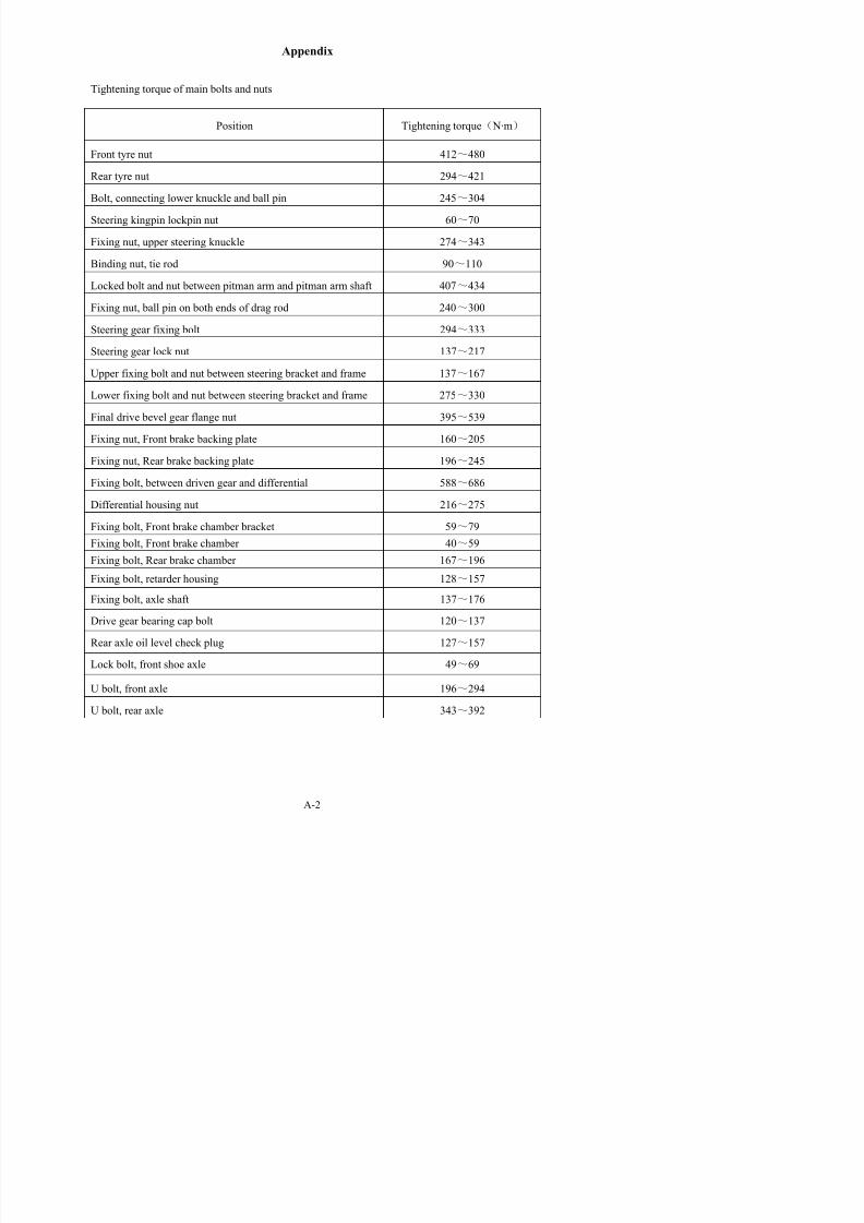
7/21/2019 Xmq6117y3 Operation Manual _philippines 4 2014 Eb100072 81
http://slidepdf.com/reader/full/xmq6117y3-operation-manual-philippines-4-2014-eb100072-81 135/144
g p
Steering kingpin lockpin nut 60~70
Fixing nut, upper steering knuckle 274~343
Binding nut, tie rod 90~110
Locked bolt and nut between pitman arm and pitman arm shaft 407~434
Fixing nut, ball pin on both ends of drag rod 240~300
Steering gear fixing bolt 294~333
Steering gear lock nut 137~217
Upper fixing bolt and nut between steering bracket and frame 137~167
Lower fixing bolt and nut between steering bracket and frame 275~330
Final drive bevel gear flange nut 395~539
Fixing nut, Front brake backing plate 160~205
Fixing nut, Rear brake backing plate 196~245
Fixing bolt, between driven gear and differential 588~686
Differential housing nut 216~275
Fixing bolt, Front brake chamber bracket 59~79
Fixing bolt, Front brake chamber 40~59
Fixing bolt, Rear brake chamber 167~196
Fixing bolt, retarder housing 128~157
Fixing bolt, axle shaft 137~176
Appendix
Lower slotted nut, damper 134~167
Fixing nut, between damper and damper bracket(M20) 88~118
Leaf spring pin locknut 54~69
Front engine mounting bracket bolt 90~110
Coupling bolt, between flywheel housing and frame 80~100
Fixing bolt, between clutch and flywheel 90~100

7/21/2019 Xmq6117y3 Operation Manual _philippines 4 2014 Eb100072 81
http://slidepdf.com/reader/full/xmq6117y3-operation-manual-philippines-4-2014-eb100072-81 136/144
Fixing bolt, between flywheel housing and clutch housing 60~75
Fixing bolt, between transmission and clutch housing 142~186
drive shaft coupling bolt 215~240
Fixing nut, transmission output shaft rear connecting panel 333~549
Appendix
Bolts torque table
Torques for bolts with metric unified threads
Dimension of bolt Torques N.m*(ft-lb)8.8 10.9 12.9
M4 3(2) 5(3) 5(4)
M5 6(4) 9(7) 10(7)
M6 10(7) 15(11) 18(13)

7/21/2019 Xmq6117y3 Operation Manual _philippines 4 2014 Eb100072 81
http://slidepdf.com/reader/full/xmq6117y3-operation-manual-philippines-4-2014-eb100072-81 137/144
M6 10(7) 15(11) 18(13)
M8 25(18) 35(26) 45(33)
M10 50(37) 75(55) 83(61)
M12 88(65) 123(91) 147(108)
M14 137(101) 196(145) 235(173)
M16 211(156) 300(221) 358(264)
M18 290(213) 412(303) 490(361)
M20 412(304) 578(426) 696(513)
M22 560(413) 785(559) 942(695)M24 711(524) 1000(738) 1200(885)
M27 1050(774) 1480(1092) 1774(1308)
M30 1420(1047) 2010(1482) 2400(1770)
Torques for bolts with metric fine threads
Dimension of boltTorques N.m*(ft-lb)
8.8 10.9 12.9
M8×1 26(19) 37(27) 48(35)
M10×1.25 52(38) 76(56) 88(65)
M12×1.25 98(72) 137(101) 126(119)
M12×1.5 93(69) 127(94) 152(112)
M14×1.5 152(112) 216(159) 255(188)
M16×1.5 225(166) 318(235) 383(282)
M18×1.5 324(239) 466(344) 554(409)
M20×1.5 461(340) 628(463) 775(572)
Appendix
The table of Lubricant, Power steering oil and Grease
1 Main assembly lubricant
Oil site Lubricant Type Level

7/21/2019 Xmq6117y3 Operation Manual _philippines 4 2014 Eb100072 81
http://slidepdf.com/reader/full/xmq6117y3-operation-manual-philippines-4-2014-eb100072-81 138/144
Engine Diesel engine oil 15W/40 API CF – 4/SG
Transmission Gear oil SAE 85W-90 API GL – 4
Main reducer Gear oil SAE 85W-90 API GL – 5
Explanation :1) Diesel engine oil--API CF -4/SG ,15W/40 , be used upwards -10℃
10W API CF – 4/SG be used between -5℃~-20℃
5W/30 API CF – 4/SG be used upwards -25℃
2) Gear oil – could be used between -20℃~50℃
2 Power steering oil
Fulfill standard: General Allison C-3. When ambient temperature is low than 10°C, please apply
DEXRON-II hydraulic fluid to steering gear; when ambient temperature is higher than 10°C, please apply
C-3/10W hydraulic fluid. C-3/10W grade oil can be used in most area all-year generally. C-3/30 grade oil
can be used in moderate temperature area all-year generally.
3 Others
Oil Site Oil used Nominate
Clutch Synthesize grade oil Nominate to use HZY4,DOT 4, or Laike 901
etc., can’t mix to use in different type grade oil
Brake system Synthesize grade oil DOT3,DOT4,DOT5.1; Laike 901,Laike
901-4,Laike 901-5
Bearing and ball pin Li - grease 2#
Appendix
JKH2028 ELECTRICAL SCHEMATIC DIAGRAM

7/21/2019 Xmq6117y3 Operation Manual _philippines 4 2014 Eb100072 81
http://slidepdf.com/reader/full/xmq6117y3-operation-manual-philippines-4-2014-eb100072-81 139/144
Appendix
ABS Air braking schematic diagram

7/21/2019 Xmq6117y3 Operation Manual _philippines 4 2014 Eb100072 81
http://slidepdf.com/reader/full/xmq6117y3-operation-manual-philippines-4-2014-eb100072-81 140/144
A-5
Appendix
Electric schematic diagram of the complete car

7/21/2019 Xmq6117y3 Operation Manual _philippines 4 2014 Eb100072 81
http://slidepdf.com/reader/full/xmq6117y3-operation-manual-philippines-4-2014-eb100072-81 141/144
A-6
Appendix
Electric schematic diagram of the complete car

7/21/2019 Xmq6117y3 Operation Manual _philippines 4 2014 Eb100072 81
http://slidepdf.com/reader/full/xmq6117y3-operation-manual-philippines-4-2014-eb100072-81 142/144
A-6
Appendix
Electric schematic diagram of the complete car

7/21/2019 Xmq6117y3 Operation Manual _philippines 4 2014 Eb100072 81
http://slidepdf.com/reader/full/xmq6117y3-operation-manual-philippines-4-2014-eb100072-81 143/144
A-6
Appendix
Electric schematic diagram of the complete car

7/21/2019 Xmq6117y3 Operation Manual _philippines 4 2014 Eb100072 81
http://slidepdf.com/reader/full/xmq6117y3-operation-manual-philippines-4-2014-eb100072-81 144/144
A-6