Xin Chen Diyu Yang Jianan Gao - University of Illinois ...
24
1 Self-standing Monopod Xin Chen Diyu Yang Jianan Gao TA: Luke ECE 445 FA 2017
Transcript of Xin Chen Diyu Yang Jianan Gao - University of Illinois ...

1
Self-standing Monopod
Xin Chen
Diyu Yang
Jianan Gao
TA: Luke
ECE 445
FA 2017

2
Contents
1. INTRODUCTION ..................................................................................................................... 3
1.1 Objectives and Background ................................................................................................. 3
1.2 High Requirements List ....................................................................................................... 3
2. DESIGN ..................................................................................................................................... 4
2.1 Block Diagram & Physical Diagram ..................................................................................... 4
2.2 Block Descriptions ................................................................................................................ 7
2.3 Requirements and Verifications ............................................................................................ 8
2.4 Supporting Materials ........................................................................................................... 12
2.4.1 Circuit Diagram ............................................................................................................ 12
2.4.2 Mathematical Model ..................................................................................................... 15
2.4.3 Requirement Calculation .............................................................................................. 16
2.5 Risk Assessment and Tolerance Evaluation ........................................................................ 17
3. Cost & Schedule ...................................................................................................................... 19
3.1 Cost...................................................................................................................................... 19
3.2 Schedule .............................................................................................................................. 20
4. Safety Statement ....................................................................................................................... 21
5. Citations .................................................................................................................................... 24
3
1. Introduction
1.1 Objectives and Background
This project intends to build an auto-balancing monopod for cameras that can replace most
of the functionalities of a tripod. The concentration of this project is mainly in control
systems.
The inspiration of our project comes from the problems with the existing tripods
photographers use: it is heavy to carry, difficult to set up, and it has only one shooting angle.
Therefore, we would like to build a monopod that can balance itself on rugged surfaces and
under various disturbances like wind. Furthermore, better than a tripod, our monopod is
lighter and easier to setup: what the user need to do is to turn on the power switch and put
the monopod at the vertical balanced position. Furthermore, the user can always manually
change the shooting angle of the monopod by holding it at a different angle. The monopod
would automatically go back to balancing position once the user releases the monopod.
1.2 High level Requirement list
1) When no disturbance is present, the monopod can balance itself with less than
+/- 5 degree oscillation at the vertical position.
2) The monopod can balance itself on a non-slippery surface with an incline of at most 15
degrees.
3) The monopod can restore to vertical balancing position from at most 30 degree leaning
angle resulted from either disturbance of wind or shooting angle adjustment by the user.
4) The length is adjustable from 1.4m to 2m. Monopod will be able to meet requirement (1)-
(3) for any length satisfying the condition above.

4
2. Design
2.1 Block diagram & Physical diagram
Figure 1. Block diagram

5
θp
mc
Figure 2: Physical Diagram[3]

6
𝑚𝑝 = 0.363𝑘𝑔 Mass of monopod
𝑚𝑟 ≈ 0.02𝑘𝑔 Mass of each propeller motor package
𝑚𝑐 ≈ 0.5𝑘𝑔 Mass of the camera
𝑙𝑚𝑎𝑥 = 2𝑚 Maximum length of monopod
𝑙𝑚𝑖𝑛 = 1.4𝑚 Minimum length of monopod
𝐹𝑟 Force produced by one propeller
𝑙𝑝 Distance from bottom to the center of mass of pendulum
𝑙𝑟 Distance from bottom to the propeller
𝑙𝑐 ≈ 𝑙 + 0.1𝑚 Distance from bottom to center of mass of camera
𝑅𝑝 = 0.15𝑚 Distance from propeller to the pod

7
2.2 block description
1. Power Supply: We use 2 Alkaline battery (9V each) for Vdd. We send required voltage to
different components using different voltage regulators.
2. Inertial Measurement Unit (IMU): We use IMU’s accelerometer to calculate the angle.
The IMU sends (x,y,z) acceleration information to Arduino to calculate the angle when it
senses the movement.
3. Microcontroller (MCU): We use a ATmega328 RedBoard AVR® ATmega MCU 8-Bit
AVR Embedded Evaluation Board as our MCU. This works as a control unit that will take
input as output from IMU, force sensor and height sensor and process to get the duty cycles
the PWM signal need for motor to balance the monopod.
4. Motor Driver: Motor driver takes PWM signals from Arduino digital I/O ports as input to
control the motors’ speed. It generates current at most 16A, which is enough for our motor.
5. Brushless motors: These motors function as actuators of our system. They are attached to
propellers that generate thrust when spinning to stabilize our monopod. The maximum rpm
is 11500 rpm. It takes inputs of three phase PWM signals. The reason we use brushless
motors over brushed motors is that it can provide more torque under the same power supply.
It operates under voltage range from 7V to 11V.
6. Force sensor: We use Interlink Electronics 34-00015 as our force sensor. The sensor will
increase resistance with the force increase. Buy measuring the resistance and comparing the
resistor and the data sheet given, we can know the weight of our camera.
7. Height sensor: We use Ultrasonic module of Arduino. Ultrasonic contains two round
looking component which are ultrasonic speakers.One of it transmitting a 40khz sound wave
and let it bounce on a solid surface. The other one will try to detect the echo that is generated
when it receives the bounce back. The total time taken for this process to complete will give
us the distances between the sensor and the object.

8
2.3 Requirements and verifications
Requirements Verifications
Microcontroller (20pts)
1. 1.The microcontroller needs to have at
least 4 I/O pins that support PWM with
a duty cycle of 50%
2. The MCU can correctly calculate data
from IMU to get the theta angle and
generate a smooth angular velocity curve
after going through a low pass filter.
3. The clock speed of Microcontroller
need to be at least bigger than 24HZ
which is the minimum sampling
frequency for the monopod we use.
1. (a) Connect the output to oscilloscope to
check the duty cycle.
2. (a) Collect 1000 data sets from the
board and monitor the data in Arduino.
(b) Export theta angle to Matlab, use the
following function to get the angular
velocity: (𝛩𝑐𝑢𝑟𝑟−𝛩𝑝𝑟𝑒𝑣)
𝛥𝑇.
(c) fit the curve, we should have less
than 10% difference except some
extreme high or low points due to
instability when measuring.
Control System (20 pts)
1. The rise time for our PID control system
should be less than 20.8ms, which
corresponds to 1
2𝑓𝑛, where 𝑓𝑛 = 24𝐻𝑧 is
the natural frequency of the system.
2. The steady-state error should be less than
10% of input signal.
3. The overshoot should be less than 5% of
input signal.
(a). Tune the PID parameters 𝑁𝑃, 𝑁𝐼, 𝑁𝐷
of the system such that the rise time and
overshoot requirements are met.
(b). Test the result by looking at the step-
response of the system.

9
IMU (15 pts)
1. The IMU needs to be calibrated such that
√𝐺𝑥2 + 𝐺𝑦
2 + 𝐺𝑧2 = 9.81
𝑚
𝑠2 with less
than 7% of percentage error in any
position, where 𝐺𝑥, 𝐺𝑦, 𝐺𝑧 are the
projection of gravitational acceleration on
each of the x, y, z axis respectively[2].
2. The IMU is accurate enough to detect +/-
5 degrees angle change in all directions at
upright position (with a percentage error
less than 30%).
1. (a). Place IMU at a certain position.
(b). Look at the output of 𝐺𝑥, 𝐺𝑦, 𝐺𝑧 from
IMU.
(c). Calculate 𝐺 = √𝐺𝑥2 + 𝐺𝑦
2 + 𝐺𝑧2 and
calculate the percentage error 𝑒 =𝐺−9.81
𝑚
𝑠2
𝐺
and see if 𝑒 ≥ 7% (The answer should be
NO).
(d). Repeat procedure (a)-(c) for different
positions.
2. (a). Place IMU at upright position.
(b). Record the two output angles 𝜃1 and
𝜃2 from microcontroller and calculate the
leaning angle: 𝜃 = √𝜃12 + 𝜃2
2.
(c). Change the position angle by 5 degree
along a random direction.
(d). Record the two output angles 𝜃1′ and
𝜃2′, and calculate the leaning angle 𝜃′ =
√𝜃1′2
+ 𝜃2′2
.
(e). Calculate angle difference:
∆𝜃 = √𝜃1′2
+ 𝜃2′2
− √𝜃12 + 𝜃2
2
(f). Calculate percentage error: 𝑒 = |∆𝜃−5°
5° |
(g). See if 𝑒 ≥ 30% (The answer should be
No).

10
3. The output of IMU is stable enough such
that the percentage error of detected angle
and actual angle is less than 15% for
10° ≤ 𝜃 ≤ 30° along any direction.
3. (a). Place IMU at a position 𝜃, where 𝜃
will be incremented from 10° to 30° by
5°each time.
(b). Follow procedure 2(b) to record and
calculate the angle 𝜃′ given by IMU
outputs.
(c). calculate the percentage error: 𝑒 =
|𝜃−𝜃′
𝜃| and see if 𝑒 ≥ 15% (the answer
should be no).
(d). Increment 𝜃 by 5° (until 𝜃 = 30° ).
(e). Repeat (b)-(d) for the new 𝜃 value.
Motor-Propeller System (15 pts)
1. The system would provide enough thrust
to meet high level requirement (3).
2. The output force of the system can be
accurately (maximum percentage
difference <= 10%) manipulated by
changing input power.
1. Set up experiment to messure the
relationship between input power and
output thrust. Find the best-fit curve for the
obtained data.
2. Test the result of our experiment by
measuring the percentage error between
theoretical output thrust and actual output
thrust under various input power level.
Power supply (10 pts)
1. The 2 alkaline battery in series supply 12V
DC voltage.
2. The maximum current the battery can
supply should be higher than 50mA,
which is the required current for 3.3V Pin
on Arduino uno.
1. We use digital Multimeter to measure the voltage
of two batteries in series. If it displays 18V. Then
it is correct.
2. We use digital Multimeter to measure the current
that the two battery in series can supply when it
is connected to the Arduino uno’s 3.3V Pin.
Motor driver (5 spts) 1. We can write a test program that takes duty cycle
input from 0 to 255 and generate PWM signal to

11
The motor should be able to change speed and
directions according to the PWM signal sent
from Microcontroller.
drive motor driver. We also hook up the motor
with motor driver. See if the motor speed
increase linearly with the increasing PWM signal
input.
Voltage Regulator (5pt)
1. 3 voltage regulators can take input voltage
up to 18V and output 2.5V, 5V, 10V as
output.
1. We connect 3 voltage regulators to 18V voltage,
use digital multimeter to check if the open circuit
output is 2.5V, 5V, 10V.
Force Sensor (5 pts)
1. The force sensor’s range need to be larger
than 500g, which is our theoretical load
weight.
2. The force sensor’s sensitivity need to be
small than 1mg/LSB
1. We check the datasheet of the force sensor to see
if the range is larger than 500g and the sensitivity
is smaller than 1mg/LSB
Geometric Model (5 pts)
1. The minimum reachable distance from
user’s body to the pod needs to be less
than 15cm for the convenience of
photographer.
2. The distance from the top of the pod to the
center of the propeller-rod system (𝑙-𝑙𝑟 )
needs to be larger than 10cm to give
convenience for attaching camera.
3. The length of the rod (Rr) needs to be
larger than the distance from propeller to
1. Build up our mechanical system such that
2. Calculate the maximum force (𝐹𝑟) required for
the propeller such that the maximum torque
produced bys propeller: 𝜏 = 𝐹𝑟 ∙ 𝑅𝑟 will be
enough to meet our high level requirement

12
the pod (Rp) for safety.
2.4 supporting materials
2.4.1 Circuit Schematics
Figure 3:Schematics for Microcontroller Circuit.

13
Figure 4: Schematics for IMU

14
Figure 5: Schematics for Power Module

15
Figure 6:Schematics for pressure Sensor
2.4.2. Mathematics Model
Our PID control system takes pendulum angle 𝜃𝑝 as input, and output the force needed to
produce for each propeller in each direction.
Net Torque added onto the system:
∆𝜏 = (𝑚𝑝𝑙𝑝 + 4𝑚𝑟𝑙𝑟 + 𝑚𝑐𝑙𝑐)𝑔 sin 𝜃𝑝 − 𝐹𝑟𝑅𝑝
∆𝜏 = −�̇�
Where 𝐿 is the angular momentum of the pendulum-propeller system, and can be
expressed as follows:
𝐿 = 𝐽𝜃�̇�
The moment of inertia of the system can be expressed as follows:
𝐽 = 𝐽𝑐 + 𝐽𝑝 + 4𝐽𝑟
𝐽𝑐 = 𝑚𝑐𝑙𝑐2
𝐽𝑟 = 𝑚𝑟𝑙𝑟2
𝐽𝑝 =1
3𝑚𝑝𝑙2
16
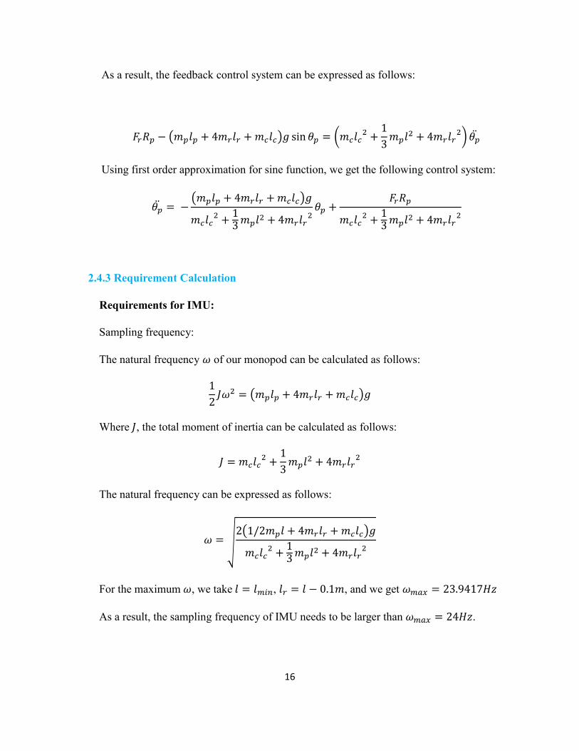
As a result, the feedback control system can be expressed as follows:
𝐹𝑟𝑅𝑝 − (𝑚𝑝𝑙𝑝 + 4𝑚𝑟𝑙𝑟 + 𝑚𝑐𝑙𝑐)𝑔 sin 𝜃𝑝 = (𝑚𝑐𝑙𝑐2 +
1
3𝑚𝑝𝑙2 + 4𝑚𝑟𝑙𝑟
2) 𝜃�̈�
Using first order approximation for sine function, we get the following control system:
𝜃�̈� = −(𝑚𝑝𝑙𝑝 + 4𝑚𝑟𝑙𝑟 + 𝑚𝑐𝑙𝑐)𝑔
𝑚𝑐𝑙𝑐2 +
13 𝑚𝑝𝑙2 + 4𝑚𝑟𝑙𝑟
2𝜃𝑝 +
𝐹𝑟𝑅𝑝
𝑚𝑐𝑙𝑐2 +
13 𝑚𝑝𝑙2 + 4𝑚𝑟𝑙𝑟
2
2.4.3 Requirement Calculation
Requirements for IMU:
Sampling frequency:
The natural frequency 𝜔 of our monopod can be calculated as follows:
1
2𝐽𝜔2 = (𝑚𝑝𝑙𝑝 + 4𝑚𝑟𝑙𝑟 + 𝑚𝑐𝑙𝑐)𝑔
Where 𝐽, the total moment of inertia can be calculated as follows:
𝐽 = 𝑚𝑐𝑙𝑐2 +
1
3𝑚𝑝𝑙2 + 4𝑚𝑟𝑙𝑟
2
The natural frequency can be expressed as follows:
𝜔 = √2(1/2𝑚𝑝𝑙 + 4𝑚𝑟𝑙𝑟 + 𝑚𝑐𝑙𝑐)𝑔
𝑚𝑐𝑙𝑐2 +
13
𝑚𝑝𝑙2 + 4𝑚𝑟𝑙𝑟2
For the maximum 𝜔, we take 𝑙 = 𝑙𝑚𝑖𝑛, 𝑙𝑟 = 𝑙 − 0.1𝑚, and we get 𝜔𝑚𝑎𝑥 = 23.9417𝐻𝑧
As a result, the sampling frequency of IMU needs to be larger than 𝜔𝑚𝑎𝑥 = 24𝐻𝑧.

17
Accuracy
According to our design requirement, we need the monopod to oscillate within +/-5
degrees around balancing position when no disturbance is present. So the minimum
accuracy requirement is as follows:
∆𝑎 = 𝑠𝑖𝑛(5°) 𝑔 = 0.0872g = 87.2m𝑔, where 𝑔 is the gravitational acceleration.
Requirement for Propeller:
According to our design requirement, the maximum leaning angle of the monopod can be
tolerated by the system is 𝜃𝑝 = ±30° . We can assume that 𝜃�̈� = 0 when 𝜃𝑝𝑚𝑎𝑥 = 30° ,
which leads to the following equation:
𝐹𝑟𝑚𝑎𝑥𝑅𝑝 − (𝑚𝑝𝑙𝑝 + 4𝑚𝑟𝑙𝑟 + 𝑚𝑐𝑙𝑐)𝑔 sin 𝜃𝑝𝑚𝑎𝑥 = 0
So the maximum force needed for each propeller can be expressed as follows:
𝐹𝑟𝑚𝑎𝑥 =(𝑚𝑝𝑙𝑝 + 4𝑚𝑟𝑙𝑟 + 𝑚𝑐𝑙𝑐)𝑔
2𝑅𝑝
Taking 𝑙𝑝 =1
2𝑙𝑚𝑎𝑥 = 1.0𝑚 , 𝑙𝑟 = 𝑙𝑚𝑎𝑥 − 0.1 = 1.9𝑚 , 𝑙𝑐 = 𝑙𝑚𝑎𝑥 + 0.1 = 2.1𝑚 , we get
the maximum forces needed from each propeller to be 𝐹𝑟𝑚𝑎𝑥 = 44.3046𝑁.
2.5 Risk assessment and tolerance evaluation
After evaluating the whole project, we may encounter the following difficulties:
Math model for the system is fundamental for our project, everything is based
on it, and since it is a multi-input and multi-output system, we may use
advanced math and physics to solve.
Microcontroller communication would be difficult if we designed a circuit
with large noise and turbulence.
IMU doesn’t have that sensitivity to detect tiny changes in angular velocity and
acceleration.

18
Soldering a PCB can be tricky since there are many connection ports on
microcontroller alone. There are also many small electronic components we need
to add on the board. It will be challenging to make sure no connection issue
occurs.
Setting up the feedback loop in the system to achieve self-control is challenging
since this is a multi-input and multi-output system. And we need to have state
feedback control or observer to achieve that. The accuracy of observer is one of
the concerns.

19
3 Cost & schedule
3.1 Cost
Labor cost
Employee Hourly rate Total hours Total cost
Xin Chen $50 $150 $7500
Diyu Yang $50 $150 $7500
Jianan Gao $50 $150 $7500
Device cost
Device quantity Model Total cost
IMU 1 SparkFun 9
DoF Razor IMU
M0
$2.5
Microcontroller 1 Arduino Uno $25
Motor 4 Uxcell motor $4
Propellers
4
Carbon Fiber
Propeller for
Mini Elec- tric
Planes, 32mm
$16
Battery 2 Duracell
Coppertop Bulk
$4
Distance sensor
1
HC-SR04Ultra-
sonic Distance
Sensor Module
$3
Motor driver 2 L298 Motor Driver
Module
$2

20
Grand total: $22556.5
3.2 Schedule
Week Task and responsibility
1/16-1/30 Group up and think about ideas
2/6 Diyu is primarily responsible for coming up with math
model with reaction wheel. Jianan Gao contact machine
shop for component detail and Xin write proposal for
our projects.
2/13 Our project has another idea toward our project, we
replaced wheel with propeller so Diyu make math model
with propeller. Xin write documents for mock design
review. Jianan Gao searches components we need and
purchases some components
2/6 Our group decided which kind of MCU, IMU and other
component detail to use in our project and purchase
them and write design review together.
2/20 Diyu programmed the MCU, Xin contacts machine shop
for details about propeller protection Jianan Gao get
ideas about PCB.
2/27 Jianan Gao and Diyu test the functionality of IMU and
PWM. Xin wires up the motors and propellers and test
with MCU in whiteboard.
3/6 Diyu build communications between MCU and IMU
and PWM. Xin build the system on whiteboard. Jianan
Gao build PCB diagrams
3/13
Our group test the basic functionality of our project.
Record the problems occurred after testing, think about

21
why problems happen. Debug the problems we
encountered for all of us.
3/20 Jianan Gao solder PCB and Xin and Diyu test basic
functionality of the project.
3/27 Diyu test additional functions such as change height and
weight. Xin document and debug problems in testing
process. Jianan Gao check circuit and power to debug.
4/3-4/10 Jianan Gao revise PCB if problems still occur. Xin and
Diyu provide assistant.
4/17 Mock demo and debug
4/24 Final demo
4. Safety statement & Ethics

22
1. Our monopod will use 4 propellers to generate torque. So one of the potential danger is that
the sharp edges of propellers can damage objects or injure a human if they are close to the
propellers. To be consistent with IEEE Code of Ethics #4: “To accept responsibility in making
decisions consistent with the safety, health, and welfare of the public.” [1] We will eliminate
this danger by designing and building a cover for each of the propeller that will protect users
get in touch with these propellers.
2. Battery safety should also be taken into consideration. Keep the battery away from fire and
teenagers. For prevention, we will put batteries into a battery package to protect users. In
addition, we will also store batteries separately with metal or other material.
3. Camera damage could also happen sometime, therefore, I will attach a camera holder using the
camera and fix the holder on this monopod carefully.
4. Soldering is dangerous so we will take great care when we are soldering something. Fume
extractor will be used at all times during the soldering process to ensure clean air. Clamps will
be used to hold the boards and components to prevent burns on the hands. All wires will be
trimmed down and insulated with electrical tape to be consistent with IEEE Code of Ethics
#4: “To accept responsibility in making decisions consistent with the safety, health, and
welfare of the public.”
5. To be consistent with IEEE Code of Ethics #4: “IEEE Code of Ethics #4: “To accept
responsibility in making decisions consistent with the safety, health, and welfare of the
public.” We will be honest about our design specification and give precise information about
our product to customers.
6. To be consistent with IEEE Code of Ethics #9: “to avoid injuring others, their property,
reputation, or employment by false or malicious action.” We will set the rule that in our
development process; any personnel except the person holding the monopod should keep

23
away from the monopod at least 5 feet. The person holding the monopod should take
precaution.

24
5. Citations
[1] “Improving fan system performance, a sourcebook for industry”. Apr. 2003
[2] Daniel J. Block, Engineering Teaching Lab Specialist, ECE Illinois
[3] Luke Adam Wendt, Graduate Student, ECE Illinois
[4] "IEEE Code of Ethics." IEEE - IEEE Code of Ethics. N.p., n.d. Web. 08 Feb. 2017.
https://www.youtube.com/watch?v=_3szGH4j_5E