X100-SERIES GRAIN AUGERS - Wheatheart … R2 3 WHEATHEART X100-SERIES GRAIN AUGERS X100-63/73/83...
106
Part Number: 30909 R2 Revised: 3 December 2016 Read this manual before using product. Failure to follow instructions and safety precautions can result in serious injury, death, or property damage. Keep manual for future reference. X100-SERIES GRAIN AUGERS X100-63/73/83 ASSEMBLY & OPERATION ORIGINAL INSTRUCTIONS
Transcript of X100-SERIES GRAIN AUGERS - Wheatheart … R2 3 WHEATHEART X100-SERIES GRAIN AUGERS X100-63/73/83...

X100-SERIES GRAIN AUGERSX100-63/73/83
ASSEMBLY & OPERATION
ORIGINAL INSTRUCTIONS
Part Number: 30909 R2
Revised: 3 December 2016
Read this manual before using product. Failure to follow instructions and safety precautions can result in serious injury, death, or property damage. Keep manual for future reference.

This product has been designed and constructed according to general engineering standardsa. Other local regulations may apply and must be followed by the operator. We strongly recommend that all personnel associated with this equipment be trained in the correct operational and safety procedures required for this product. Periodic reviews of this manual with all employees should be standard practice. For your convenience, we include this sign-off sheet so you can record your periodic reviews.
a. Standards include organizations such as the American Society of Agricultural and Biological Engineers, American National Standards Institute, Canadian Standards Association, International Organization for Standardization, EN Standards, and/or others.
Date Employee Signature Employer Signature

WHEATHEART X100-SERIES GRAIN AUGERS X100-63/73/83
TABLE OF CONTENTS
1. Introduction .......................................................................................................................... 71.1. Overview .................................................................................................................. 81.1.1. Auger Power Source .................................................................................. 91.1.2. Grain Transfer Boot .................................................................................. 101.1.3. Grain Hopper ............................................................................................ 111.1.4. Auger Tube Hydraulic Lift ......................................................................... 13
2. Safety .................................................................................................................................. 152.1. General Safety Information .................................................................................... 152.2. Assembly Safety..................................................................................................... 162.3. Operation Safety .................................................................................................... 162.4. PTO Safety............................................................................................................. 182.5. Hydraulic Safety ..................................................................................................... 192.6. Transport & Placement Safety ............................................................................... 202.7. Maintenance Safety................................................................................................ 202.8. Safety Decals ......................................................................................................... 21
2.8.1. Decal Installation/Replacement ................................................................ 212.8.2. Safety Decal Locations and Details.......................................................... 21
3. Assembly ............................................................................................................................ 273.1. General Assembly .................................................................................................. 273.2. Assemble the Auger Tube...................................................................................... 29
3.2.1. Identify and Arrange Auger Tube Sections............................................... 293.2.2. Connect Auger Tube Sections Together .................................................. 313.2.3. Install the Boot on the Auger tube ............................................................ 323.2.4. Install the Discharge Spout....................................................................... 353.2.5. Set the Thrust Adjuster............................................................................. 363.2.6. Apply Logo and Model Decals on the Auger Tubes ................................. 37
3.3. Install Truss Towers ............................................................................................... 403.4. Install Truss Cables................................................................................................ 423.5. Assemble the Frame .............................................................................................. 453.6. Connect the Lower Frame Arms ............................................................................ 473.7. Connecting the Short Cross Member and Upper Scissors arms............................ 48
3.7.1. Install Hydraulic Lift Cylinder .................................................................... 493.8. Assemble the Wheel Hub and Install Tires ............................................................ 503.9. Connect the Auger Tube to the Frame................................................................... 513.10. Connect Hydraulic Hoses and Ball Valve............................................................. 533.11. Connect the PTO Driveline................................................................................... 553.12. Install Low Profile Intake Hopper.......................................................................... 563.13. Install the Hopper Lift Extension........................................................................... 593.14. Install Hopper Lift Arm and Winch........................................................................ 593.15. Install the Hitch Jack ............................................................................................ 623.16. Install the Plastic Manual Container ..................................................................... 633.17. Auger-to-Tractor Hookup...................................................................................... 64
30909 R2 3
WHEATHEART X100-SERIES GRAIN AUGERS
X100-63/73/83
TABLE OF CONTENTS
4. Transport and Placement .................................................................................................. 674.1. Transport Procedure............................................................................................... 674.2. Placement Procedure ............................................................................................. 694.3. Positioning Tractor for Right-angle Drive Operation............................................... 724.4. Lowering the Auger ................................................................................................ 74
5. Operation ............................................................................................................................ 755.1. Operator Controls .................................................................................................. 755.2. Pre-Operation ......................................................................................................... 77
5.2.1. Checklist ................................................................................................... 775.2.2. PTO Drive ................................................................................................. 785.2.3. Hydraulics ................................................................................................. 78
5.3. Operating Procedures ............................................................................................ 795.3.1. Initial Start-Up ........................................................................................... 795.3.2. Normal Start.............................................................................................. 805.3.3. Normal Shutdown ..................................................................................... 815.3.4. Emergency Stop / Full-Tube Restart ........................................................ 825.3.5. Lowering & Completion............................................................................. 825.3.6. Reverser Operation .................................................................................. 84
6. Maintenance and Storage.................................................................................................. 876.1. Maintenance Intervals ............................................................................................ 876.2. Fluids and Lubricants ............................................................................................. 886.3. Maintenance Procedures........................................................................................ 88
6.3.1. Visual Inspection....................................................................................... 886.3.2. Hydraulic Hose and Coupler Inspection ................................................... 896.3.3. Machine Greasing..................................................................................... 896.3.4. Hopper Lift Cable Inspection .................................................................... 926.3.5. Winch and Pulley Servicing ...................................................................... 926.3.6. Swing Tube Coupler Chain Servicing ....................................................... 936.3.7. Boot and Hopper Chain Drive Servicing ................................................... 946.3.8. Gearbox Oil Level ..................................................................................... 956.3.9. Machine Cleaning ..................................................................................... 966.3.10. Tire Pressure Check ............................................................................... 966.3.11. Wheel Bearings Repack ......................................................................... 966.3.12. Wheel Bolt Tightening............................................................................. 966.3.13. Truss Cable Adjustment ......................................................................... 976.3.14. Changing Upper/Lower Gearbox Oil....................................................... 97
6.4. Storage ................................................................................................................... 98
7. Troubleshooting ................................................................................................................. 99
4 30909 R2

WHEATHEART X100-SERIES GRAIN AUGERS X100-63/73/83
TABLE OF CONTENTS
8. Appendix........................................................................................................................... 1018.1. Specifications ....................................................................................................... 1018.2. Bolt Torque Values............................................................................................... 1028.3. Lift Cylinder Hydraulics......................................................................................... 103
Limited Warranty ................................................................................................................... 105
30909 R2 5

WHEATHEART X100-SERIES GRAIN AUGERS
X100-63/73/83
6 30909 R2

WHEATHEART - X100-SERIES GRAIN AUGERS 1. INTRODUCTION
X100-63/73/83
1. IntroductionThank you for purchasing a Wheatheart grain auger. Before using, please read this manual and understand the various features of the equipment and precau-tions for efficient and safe operation.
Keep this manual handy for frequent reference and to review with new personnel. A sign-off form is supplied on the inside front cover to record your safety reviews. Call your local distributor or dealer if you need assistance or additional information.
This manual should be regarded as part of the equipment. Suppliers of both new and second-hand equipment are advised to retain documentary evidence that this manual was provided with the machine.
Serial Number:
*Serial number is located on the lower tube.
30909 R2 7

1. INTRODUCTION WHEATHEART - X100-SERIES GRAIN AUGERS
X100-63/73/83
1.1. OVERVIEW
X100 augers are equipped with standard features that include a hydraulically controlled main auger tube lift, a low-profile grain hopper (left or right side operation), service access doors, and a PTO shaft for auger power.
Available option kits include:
• Hydraulic Winch• Hydraulic Power Swing for Hopper• Electric Power Swing for Hopper• Right Angle Drive• 540 RPM PTO Reverser• Standard hopper
Figure 1.1 X100 Series Auger (73’ model shown)
8 30909 R2

WHEATHEART - X100-SERIES GRAIN AUGERS 1. INTRODUCTION
X100-63/73/83
1.1.1. AUGER POWER SOURCE
The power source for the auger is a standard 540 RPM tractor PTO (see Figure 1.2). An optional Right-Angle PTO Drive kit allows the auger to be powered by a tractor positioned at a 90 degree angle to the auger (Figure 1.3).
An optional 540 RPM Reverser kit provides a similar reverser capability for 540 RPM PTO connections.
Figure 1.2 Standard PTO
Figure 1.3 Right Angle PTO Drive Kit
30909 R2 9

1. INTRODUCTION WHEATHEART - X100-SERIES GRAIN AUGERS
X100-63/73/83
1.1.2. GRAIN TRANSFER BOOT
The grain transfer boot is located at the bottom of the main auger tube, and contains gearing for power transfer as well as flights for transferring grain.
PTO driveline connection (including connection to the optional 540 RPM PTO Reverser) is provided on the back of the boot, above the tractor hitch (and hitch jack).
The ball valve used to raise or lower the main auger tube is located on the side of the boot (see figure below), as is the manual winch used to raise and lower the grain hopper (see section 5.1. for further information on auger controls).
Several access hatches are provided for maintenance and repair, as well as an overflow panel on the swing-arm spout head and a clean-out hatch at the bottom of the boot.
Figure 1.4 Grain Transfer Boot
GRAIN TRANSFER BOOT
SWING ARM SPOUT HEAD
OVERFLOW PANEL
PTO DRIVELINE
HITCH
HITCH JACK
SPOUT HEADSERVICE COVER
CLEAN-OUT HATCH
MANUAL WINCH (HOPPER)
BALL VALVE
10 30909 R2

WHEATHEART - X100-SERIES GRAIN AUGERS 1. INTRODUCTION
X100-63/73/83
1.1.3. GRAIN HOPPER
The low-profile grain hopper is designed to be rolled into position to receive grain for transfer through the boot to the auger discharge spout. Ground clearance can be adjusted by raising or lowering the position of the hopper wheel axles (see “Install Low Profile Intake Hopper” on page 56).
The grain hopper must be lifted and secured for transport using the hopper lift arm, winch (hydraulic or manual operation, according to the installed option), and transport chain and hook (see Figure 1.6).
The grain hopper provides service to the side of the auger that it is installed on, but the hopper, lift arm, and winch can be quickly reconfigured to install the hopper on the other side if required.
Do not approach, open or close the maintenance hatch located on the transition between the swing are tube and the hopper unless all power to the auger is locked out.
DANGER
Rotating Auger Hazard
Contact with rotating flighting will result in amputation or severe laceration.
DO NOT operate with guards removed or modified.
Keep hands and feet away from rotating auger.
Tie up long hair and remove jewellery.
DO NOT wear loose-fitting clothing or items that could become caught.
Shut off and lock out the power source before unplugging or cleaning.
30909 R2 11

1. INTRODUCTION WHEATHEART - X100-SERIES GRAIN AUGERS
X100-63/73/83
Figure 1.5 Grain Hopper
Figure 1.6 Grain Hopper Lifted into Transport Position
HOPPER
FLIGHTS AND
SWING TUBE
MAINTENANCE HATCH
SPOUT HEAD
MAIN AUGER TUBE
BOOT
FLIGHT GUARDING
TRANSPORT CHAIN
AND HOOK
WINCH CHAINAND HOOK
12 30909 R2

WHEATHEART - X100-SERIES GRAIN AUGERS 1. INTRODUCTION
X100-63/73/83
1.1.4. AUGER TUBE HYDRAULIC LIFT
The auger tube is raised and lowered using a single-acting hydraulic cylinder powered by the hydraulic supply of the connected tractor. the main auger tube is raised by extending the cylinder, and lowered by allowing the cylinder to retract.
A hydraulic ball valve mounted on the side of the grain pick-up boot controls flow of hydraulic fluid to the lift cylinders, and with appropriate use of the hydraulic controls on the connected tractor, allows the main auger tube to be raised, lowered, or locked at a specific height during operation (see “Operator Controls” on page 75).
Figure 1.7 Auger Tube Hydraulic Lift Cylinder
30909 R2 13

1. INTRODUCTION WHEATHEART - X100-SERIES GRAIN AUGERS
X100-63/73/83
14 30909 R2

WHEATHEART - X100-SERIES GRAIN AUGERS 2. SAFETY
X100-63/73/83
2. Safety2.1. GENERAL SAFETY INFORMATION
The Safety Alert symbol identifies important safety messages on the product and in the manual. When you see this symbol, be alert to the possibility of personal injury or death. Follow the instructions in the safety messages.
Why is SAFETY important?
• Accidents disable and kill.• Accidents cost.• Accidents can be avoided.
SIGNAL WORDS: Note the use of the signal words DANGER, WARNING, CAUTION, and NOTICE with the safety messages. The appropriate signal word for each message has been selected using the definitions below as a guideline.
DANGER
Indicates an imminently hazardous situation that, if not avoided, will result in serious injury or death.
WARNING
Indicates a hazardous situation that, if not avoided, could result in serious injury or death.
CAUTION
Indicates a hazardous situation that, if not avoided, may result in minor or moderate injury.
NOTICE
Indicates a potentially hazardous situation that, if not avoided, may result in property damage.
30909 R2 15

2. SAFETY WHEATHEART - X100-SERIES GRAIN AUGERS
X100-63/73/83
YOU are responsible for the SAFE use and maintenance of your equipment. YOU must ensure that you and anyone else who is going to work around the equipment understands all procedures and related SAFETY information contained in this manual.
Remember, YOU are the key to safety. Good safety practices not only protect you, but also the people around you. Make these practices a working part of your safety program.
Important: Below are general instructions that apply to all safety practices. Any instructions specific to a certain safety practice (e.g., Operational Safety), can be found in the appropriate section. Always read the complete instructional sections and not just these safety summaries before doing anything with the equipment.
• It is the equipment owner, operator, and maintenance personnel's responsi-bility to read and understand ALL safety instructions, safety decals, and man-uals and follow them when assembling, operating, or maintaining the equipment. All accidents can be avoided.
• Equipment owners must give instructions and review the information initially and annually with all personnel before allowing them to operate this product. Untrained users/operators expose themselves and bystanders to possible serious injury or death.
• Use this equipment for its intended purposes only.• Do not modify the equipment in any way without written permission from the
manufacturer. Unauthorized modification may impair the function and/or safety, and could affect the life of the equipment. Any unauthorized modifica-tion of the equipment voids the warranty.
• Do not allow any unauthorized person in the work area.
2.2. ASSEMBLY SAFETY
• Read and understand the assembly instructions to get to know the sub-assemblies and hardware that make up the equipment before proceeding to assemble the product.
• Do not take chances with safety. The components are large, heavy, and can be hard to handle. Always use the proper tools, stands, jacks, and hoists for the job.
• Always have two or more people assembling the equipment. Because of the weight, do not attempt assembly alone.
2.3. OPERATION SAFETY
• Have another trained person nearby who can shut down the auger in case of accident. Always work with a second trained person around augers.
• Do not operate with any of the safety guards removed.• Keep body, hair, and clothing away from moving parts. Stay away from intake
during operation.• Inspect lift cable before using auger. Replace if frayed or damaged. Make
sure it is seated properly in cable sheaves and cable clamps are secure.
16 30909 R2

WHEATHEART - X100-SERIES GRAIN AUGERS 2. SAFETY
X100-63/73/83
• Operate auger on level ground free of debris. If ground is uneven, anchor the auger to prevent tipping or upending.
• Augers are not insulated. Keep away from electrical lines. Electrocution can occur without direct contact.
• Support the discharge end and/or anchor the intake end before operating to prevent upending.
• Do not use auger as a hoist.• Empty auger before raising or lowering.• Lower auger at completion of operation or when not in use. Auger could drop
rapidly in case of cable break or hydraulic failure (where applicable).• Keep the work area clean and tidy.
• Do not get on or beneath auger when raising or lowering intake hitch jack, or when auger is supported by hitch jack.
• Do not operate auger with the service or cleanout doors open or unlatched.
30909 R2 17

2. SAFETY WHEATHEART - X100-SERIES GRAIN AUGERS
X100-63/73/83
Figure 2.1
2.4. PTO SAFETY
• Never use a PTO driveline without a rotating shield in good working order.• Ensure PTO driveline is securely attached at both ends before operating.• Before starting tractor, turn power to PTO to the off position (where applica-
ble).• Keep body, hair, and clothing away from rotating PTO driveline.• Ensure the PTO driveline shields turn freely on the PTO driveline.
BIN
18 30909 R2

WHEATHEART - X100-SERIES GRAIN AUGERS 2. SAFETY
X100-63/73/83
• Do not exceed operating speed of 540 rpm.• Keep u-joint angles small and equal. Do not exceed recommended operating
length for PTO driveline.
2.5. HYDRAULIC SAFETY
• Wear proper hand and face protection when searching for hydraulic leaks. Escaping fluid under pressure can penetrate the skin, causing serious injury like gangrene. In case of accident, see a doctor immediately.
• Fluid leaks in the hydraulic lift cylinders or hoses will allow the auger to lower inadvertently. Repair all leaks and breaks immediately. Rupture could cause damage and/or personal injury.
• A hydraulic lift is faster than a conventional hand crank—always clear area of personnel before raising or lowering.
• Do not disconnect hydraulic couplers when hydraulic system is pressurized. For the correct procedure, consult this manual or your tractor manual.
• Relieve pressure before unhooking hydraulic lines.• Inspect hydraulic fittings and hoses for damage on a daily basis. Repair if
damaged.• Ensure that the hydraulic line(s) is (are) properly connected and secure.• Keep hydraulic line(s) away from moving parts.• Clean connections before connecting to equipment.
30909 R2 19

2. SAFETY WHEATHEART - X100-SERIES GRAIN AUGERS
X100-63/73/83
2.6. TRANSPORT & PLACEMENT SAFETY
• Transport auger in full down position with slight ten-sion on cable.
• Properly place hitch pin and securely attach safety chain. Use a type of hitch pin that will not allow auger to separate from towing vehicle.
• Always attach an SMV (slow moving vehicle) sign before transporting auger. Equip the auger with the necessary lights for transportation where required by law. Always use hazard warning flashers on the tractor/towing vehicle when transporting unless prohibited by law.
• Always travel at a safe speed, never exceeding 15 mph (24 km/hr). Reduce speed on rough surfaces and be cautious when turning corners or meeting traffic.
• Before raising/lowering/moving the auger, make sure the area around the auger is clear of obstruc-tions and/or untrained personnel. Never allow any-one to stand on or beneath auger while transporting or placing auger.
• Do not transport auger on slopes greater than 20°.• Wheels must be free to move when raising or low-
ering auger.• Never attempt to move auger manually. To do so
will result in serious injury.• Before moving auger, check and double check for overhead obstructions and/
or electrical wires. Electrocution can occur without direct contact.• Disconnect PTO driveline from tractor before moving auger or tractor and
secure in transport saddle (where applicable).• Raise intake feed hopper into transport position and lock hopper lift winch
before transporting or moving auger. Intake feed side of hopper must face main auger when in transport position.
• Do not operate auger with intake hopper in transport position. This will cause damage to the u-joint.
2.7. MAINTENANCE SAFETY
• Shut down and lock out all power before attempting maintenance of any kind. If applicable, disconnect PTO driveline from tractor or hydraulic hoses on units with hydraulic drive hoppers.
• After maintenance is complete, replace and secure all safety guards and safety devices, and if applicable, service doors and cleanout covers.
• Support auger tube before attempting maintenance on the undercarriage assembly. Auger should be in full down position for maintenance.
20 30909 R2

WHEATHEART - X100-SERIES GRAIN AUGERS 2. SAFETY
X100-63/73/83
• Use only genuine Wheatheart replacement parts or equivalent. Replacement parts such as intake guards, pulley guards, PTO driveline shields, winches, and lift cables must meet ASABE standards or serious injury may result. Use of unauthorized parts will void warranty. If in doubt, contact Wheatheart or your Wheatheart dealer.
• Do not modify any auger components without authorization from Wheatheart. Modification can be dangerous and result in serious injuries.
2.8. SAFETY DECALS
• Keep safety decals clean and legible at all times.• Replace safety decals that are missing or have become illegible. See decal
location figures that follow.• Replaced parts must display the same decal(s) as the original part.• Replacement safety decals are available free of charge from your distributor,
dealer, or factory.
2.8.1. DECAL INSTALLATION/REPLACEMENT
1. Decal area must be clean and dry, with a temperature above 50°F (10°C).2. Decide on the exact position before you remove the backing paper.3. Align the decal over the specified area and carefully press the small portion
with the exposed sticky backing in place.4. Slowly peel back the remaining paper and carefully smooth the remaining
portion of the decal in place.5. Small air pockets can be pierced with a pin and smoothed out using the sign
backing paper.
2.8.2. SAFETY DECAL LOCATIONS AND DETAILS
Replicas of the safety decals that are attached to the equipment and their messages are shown in the figure(s) that follow. Safe operation of the equipment requires that you familiarize yourself with the various safety decals and the areas or particular functions that the decals apply to, as well as the safety precautions that must be taken to avoid serious injury, death, or damage.
Please review the decals shown. If your auger does not have these decals, they are available upon request. Please specify which decals you need.
* Wheatheart reserves the right to update safety decals without notice. Safety decals may not be exactly as shown.
30909 R2 21

2. SAFETY WHEATHEART - X100-SERIES GRAIN AUGERS
X100-63/73/83
Figure 2.2 Hydraulic Cylinder Safety Decals
WARNINGHIGH PRESSURE FLUID HAZARD
Hydraulic fluid can cause serious injury if it penetrates the skin. If it does, see a doctor immediately. • Relieve pressure before unhooking hydraulic line. • Wear proper hand and eye protection, and use wood
or cardboard, not hands, when searching for leaks.60802adanaC ni edaM
DECAL #20806
APPLY DECAL NEAR HYDRAULIC CYLINDER PORT
22 30909 R2

WHEATHEART - X100-SERIES GRAIN AUGERS 2. SAFETY
X100-63/73/83
Figure 2.3 PTO and Tow Bar Safety Decals
DECAL #18859
NOTIC
E
Disco
nnec
t PTO
drive
line
from t
ractor
befor
e mov
ing
equip
ment.
If atta
ched
, driv
eline w
ill bo
ttom
out, s
evere
ly da
magin
g the
CV u-
joint
and l
ower
flight
shaft
.
See m
anua
l for
maint
enan
ce.
95881adanaC ni eda M
NOTICE
Disconnect PTO driveline from tractor before moving equipment.If attached, driveline will bottom out, severely damaging the CV u-joint and lower flight shaft. See manual for maintenance.
95881adanaC ni edaM
NOTICE
• Follow dimensions above for correct auger-to-tractor hookup.
To prevent damageduringauger-to-tractor hookup:
• Adjust drawbar as needed.• See operation manual for complete details.
• Auger must be on level ground and in full down position when measuring.
17531Made in Canada
DECAL #17531
30909 R2 23

2. SAFETY WHEATHEART - X100-SERIES GRAIN AUGERS
X100-63/73/83
Figure 2.4 Auger Tube and Hopper Safety Decals
DANGER
ELECTROCUTION HAZARDTo prevent death or serious injury:
• When operating or moving, keep equipment away from overhead power lines and devices.
• Fully lower equipment and truck box before moving.
This equipment is not insulated.Electrocution can occur without direct contact.
Made in Canada 20816
WARNING
To prevent serious injury or death:
• Read and understand the manual before assembling, operating, or maintaining the equipment.
• Only trained personnel may assemble, operate, or maintain the equipment.
• Children and untrained personnel must be kept outside of the work area.
• If the manual, guards, or decals are missing or damaged, contact factory or dealer for replacements.
• Lock out power before performing maintenance.
• To prevent equipment collapse, support equipment tube while disassembling certain components.
• When equipped, electric motors must be grounded.Disconnect power before resetting overloads.
Made in Canada 20807
WARNING
ENTANGLEMENT HAZARDTo prevent serious injury or death:
• Keep body, hair, and clothing away from rotating pulleys, belts, chains, and sprockets.
• Do not operate with any guard removed or modified. Keep guards in good working order.
• Shut off and remove key or lock out power source before inspecting or servicing machine.
Made in Canada 20804
WARNINGTRANSPORT HAZARD
To prevent serious injury or death:
• Securely attach equipment to vehicle with correct pin and safety chains.
• Use a tow vehicle to move equipment.31171adanaC ni edaM
NOTICEThis equipment is not intended for transport on public roads. If it must be moved, check local regulations.To avoid damaging the equipment:
• Be careful when turning corners.• Watch for low overhead objects.• Retract axles before transporting unit.
17378Made inCanada
DECAL #20813
DECAL #20816
DECAL #20807
DECAL #20804
DECAL #17113
DECAL # 17377
WARNING
UPENDING HAZARDTo prevent death or serious injury:• Anchor intake end and/or support discharge end to
prevent upending.
• Auger intake end must always have downward weight. Do not release until attached to tow bar or resting on ground.
• Do not raise auger intake end above tow bar height.
• Empty auger and fully lower before moving.Made in Canada 20811
DECAL #20811
(LOCATED ON HOPPER CHAIN GUARD)
DANGER
ROTATING FLIGHTING HAZARDTo prevent death or serious injury:
• KEEP AWAY from rotating auger flighting.
• DO NOT remove or modify auger flighting guards, doors, or covers. Keep in good working order. Have replaced if damaged.
• DO NOT operate the auger without all guards, doors, and covers in place.
• NEVER touch the auger flighting. Use a stick or other tool to remove an obstruction or clean out.
• Shut off and lock out power to adjust, service, or clean.Made in Canada 20813
NOTICETo lower equipment, start tractor, then engage hydraulic lever in down position.
• This pumps oil to upper chamber of the hydraulic cylinders preventing overfill of tractor reservoir.
77371adanaC ni edaM
DECAL # 17378
X100-83 ONLY
X100-83 ONLY
24 30909 R2

WHEATHEART - X100-SERIES GRAIN AUGERS 2. SAFETY
X100-63/73/83
Figure 2.5 Boot Safety Decals
NOTICE
• Follow dimensions above for correct auger-to-tractor hookup.
To prevent damageduringauger-to-tractor hookup:
• Adjust drawbar as needed.• See operation manual for complete details.
• Auger must be on level ground and in full down position when measuring.
17531Made in Canada
DANGERROTATING PTO DRIVELINE HAZARD
To prevent serious injury or death:• Keep body, hair, and clothing away from rotating PTO driveline.• Do not operate equipment unless all driveline, tractor, and
equipment shields are in place and in good working order.• Make certain the driveline shields turn freely on driveline.• Make certain the driveline is securely attached at both ends.• Do not exceed operating speed of 540 rpm.• Keep u-joint angles small and equal. Do not exceed maximum
recommended length for PTO driveline.Made in Canada 20818
CAUTIONTo prevent personal injury or damage to equipment, close valve in lift cylinder hydraulic line after raising equipment into position. 17107
Made in Canada
NOTICETo prevent damage, wheels must be free to move when raising or lowering equipment.When equipment is positioned, chock all wheels. Made in Canada 19960
DANGER
ROTATING FLIGHTING HAZARDTo prevent death or serious injury:
• KEEP AWAY from rotating auger flighting.
• DO NOT remove or modify auger flighting guards, doors, or covers. Keep in good working order. Have replaced if damaged.
• DO NOT operate the auger without all guards, doors, and covers in place.
• NEVER touch the auger flighting. Use a stick or other tool to remove an obstruction or clean out.
• Shut off and lock out power to adjust, service, or clean.Made in Canada 20813
DANGERROTATING FLIGHTING INSIDETo prevent serious injury or death, do not operate auger unless swing-hopper is securely attached to boot.
49071adanaC ni edaM
DECAL #20813
DECAL #20807
DECAL #19960
DECAL #17531
DECAL #20804
DECAL #17094
WARNINGTRANSPORT HAZARD
To prevent serious injury or death:
• Securely attach equipment to vehicle with correct pin and safety chains.
• Use a tow vehicle to move equipment.31171adanaC ni edaM
DECAL #17113
DANGER
ELECTROCUTION HAZARDTo prevent death or serious injury:
• When operating or moving, keep equipment away from overhead power lines and devices.
• Fully lower equipment and truck box before moving.
This equipment is not insulated.Electrocution can occur without direct contact.
Made in Canada 20816
DECAL #20816
WARNINGMISSING GUARD HAZARDTo prevent serious injury or death, shut off power and reattach guard before operating machine.
20803Made in Canada
DECAL #20803PLACED BEHIND GUARD
WARNING
To prevent serious injury or death:
• Read and understand the manual before assembling, operating, or maintaining the equipment.
• Only trained personnel may assemble, operate, or maintain the equipment.
• Children and untrained personnel must be kept outside of the work area.
• If the manual, guards, or decals are missing or damaged, contact factory or dealer for replacements.
• Lock out power before performing maintenance.
• To prevent equipment collapse, support equipment tube while disassembling certain components.
• When equipped, electric motors must be grounded.Disconnect power before resetting overloads.
Made in Canada 20807
WARNING
ENTANGLEMENT HAZARDTo prevent serious injury or death:
• Keep body, hair, and clothing away from rotating pulleys, belts, chains, and sprockets.
• Do not operate with any guard removed or modified. Keep guards in good working order.
• Shut off and remove key or lock out power source before inspecting or servicing machine.
Made in Canada 20804
DECAL #20818
DECAL #17107
30909 R2 25

2. SAFETY WHEATHEART - X100-SERIES GRAIN AUGERS
X100-63/73/83
Figure 2.6 Roll-Over / Transport Safety
WARNINGROLLOVER / TRANSPORT
HAZARDTo prevent serious injury or death:
• Fully extend axles before raising auger tube.
• Retract axles before transporting.20812
Made inCanada
DECAL #20812
NOTE: THIS WARNING DECAL IS ONLY INCLUDED ON AUGERS 83’ AND LONGER.
INSTALL A DECAL ON TOP OF EACH SIDE OF THE AXLE, AND ONE ON THE LOWER AUGER TUBE, AS INDICATED.
26 30909 R2

WHEATHEART - X100-SERIES GRAIN AUGERS 3. ASSEMBLY
X100-63/73/83
3. Assembly
Before beginning assembly, familiarize yourself with all the sub-assemblies and hardware making up the auger. Have all parts on hand and arrange them for easy access. Carry out assembly in a large open area with a level surface.
Important: Always have 2 or more people assembling the equipment. Because of the weight, do not attempt assembly alone.
Augers are available in various combinations. In most cases, the following instructions will apply to all augers. Where the assembly information varies, additional instructions will be included and will be indicated with an arrow.
Note: Non-driveline options such as the hydraulic winch and hydraulic/electric power swing are compatible with all other options that can be installed on the auger. Driveline options (Right angle Drive, 540 RPM PTO Reverser) are not compatible with other driveline options, but are compatible with non-driveline options such as the hydraulic winch and hydraulic/electric power swing.
3.1. GENERAL ASSEMBLY
1. Select an assembly area that is level, has a firm or hard surface and is free of debris. Be sure it is large enough to allow access from all sides when the components are being assembled.
2. If assembling inside a building, be sure the ceiling is at least 14’ (4.27 m) high to provide clearance when installing the undercarriage
3. Bring all the tools, blocks, stands, jacks, and hoists to the assembly area before starting.
4. The following tools and equipment are required to assemble the machine:
• 11-14 Support stands (tube section supports, three per tube)• Four Saw horses (1200 lb / 544.3 kg bearing capacity)• One Standard socket set and wrench set• One Torque wrench • One Standard 25’ (7.62 m) tape measure• One 2’ level• One 8” level magnetic• Two C-clamps or vise grips• One Picker with minimum reach of 12’ (3.66 m) 4000-6000 lb
(1814 - 2722 kg) lifting capacity• One 100’ (30 m) measuring tape• One Tire gauge• One Tire chuck• 6-10 Wood blocks (2x4's or smaller)
WARNING Before continuing, ensure you have read and understand the relevant information in the safety section. Safety information is provided to help prevent serious injury, death, or property damage.
30909 R2 27
3. ASSEMBLY WHEATHEART - X100-SERIES GRAIN AUGERS
X100-63/73/83
• Grease• Impact wrench and sockets• 2+ Steel Punches (for aligning bolt holes)
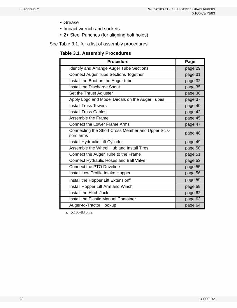
See Table 3.1. for a list of assembly procedures.
Table 3.1. Assembly Procedures
Procedure Page
Identify and Arrange Auger Tube Sections page 29
Connect Auger Tube Sections Together page 31
Install the Boot on the Auger tube page 32
Install the Discharge Spout page 35
Set the Thrust Adjuster page 36
Apply Logo and Model Decals on the Auger Tubes page 37
Install Truss Towers page 40
Install Truss Cables page 42
Assemble the Frame page 45
Connect the Lower Frame Arms page 47
Connecting the Short Cross Member and Upper Scis-sors arms
page 48
Install Hydraulic Lift Cylinder page 49
Assemble the Wheel Hub and Install Tires page 50
Connect the Auger Tube to the Frame page 51
Connect Hydraulic Hoses and Ball Valve page 53
Connect the PTO Driveline page 55
Install Low Profile Intake Hopper page 56
Install the Hopper Lift Extensiona
a. X100-83 only.
page 59
Install Hopper Lift Arm and Winch page 59
Install the Hitch Jack page 62
Install the Plastic Manual Container page 63
Auger-to-Tractor Hookup page 64
28 30909 R2

WHEATHEART - X100-SERIES GRAIN AUGERS 3. ASSEMBLY
X100-63/73/83
3.2. ASSEMBLE THE AUGER TUBE
3.2.1. IDENTIFY AND ARRANGE AUGER TUBE SECTIONS
1. Align tube sections on a series of support stands, placing a support stand at the end of each tube (see the figures below for correct tube identification and positioning).
2. As tubes sections are added, make sure that support stands are at equal heights across all tubes to ensure that tubes are level with each other. Otherwise, use some form of shim to keep the tubes level across all of the support stands.
Important: 3. Strap tubes to the support stands to prevent the tubes from rolling off the stands.
Figure 3.1 X100-63 Auger Tube Sections
21729
21731
21733
30909 R2 29

3. ASSEMBLY WHEATHEART - X100-SERIES GRAIN AUGERS
X100-63/73/83
Figure 3.2 X100-73 Auger Tube Sections
Figure 3.3 X100-83 Auger Tube Sections
21735
21731
21733
21735
21737
21739
21741
30 30909 R2

WHEATHEART - X100-SERIES GRAIN AUGERS 3. ASSEMBLY
X100-63/73/83
3.2.2. CONNECT AUGER TUBE SECTIONS TOGETHER
Important: Always strap tubes to the support stands to prevent the tubes from rolling off the stands.
Note: Assemble the auger tube starting with the discharge section and working toward the intake section.
1. Bolt tube sections together (see Figure 3.4 for details), working from the spout end (upper tube) toward the discharge end (lower tube):a. Align flightings to ensure a continual spiral of auger surface, and connect
flight shafts with 7/16” x 3” bolts and 7/16” locknuts.
b. As flight shafts are connected, slide tube sections together and secure with 7/16'' X 1” and 7/16” locknuts.
Figure 3.4 Connecting Auger Tubes Sections and Flights
7/16” LOCKNUT [19598]
7/16” X 1”
7/16” LOCKNUTS
7/16” X 3” BOLT [19546]
[19598]
BOLTS [19542]
30909 R2 31
3. ASSEMBLY WHEATHEART - X100-SERIES GRAIN AUGERS
X100-63/73/83
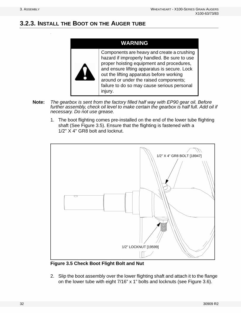
3.2.3. INSTALL THE BOOT ON THE AUGER TUBE
.\
Note: The gearbox is sent from the factory filled half way with EP90 gear oil. Before further assembly, check oil level to make certain the gearbox is half full. Add oil if necessary. Do not use grease.
1. The boot flighting comes pre-installed on the end of the lower tube flighting shaft (See Figure 3.5). Ensure that the flighting is fastened with a 1/2'' X 4'' GR8 bolt and locknut.
Figure 3.5 Check Boot Flight Bolt and Nut
2. Slip the boot assembly over the lower flighting shaft and attach it to the flange on the lower tube with eight 7/16” x 1” bolts and locknuts (see Figure 3.6).
WARNING
Components are heavy and create a crushing hazard if improperly handled. Be sure to use proper hoisting equipment and procedures, and ensure lifting apparatus is secure. Lock out the lifting apparatus before working around or under the raised components; failure to do so may cause serious personal injury.
1/2” X 4” GR8 BOLT [18947]
1/2” LOCKNUT [19599]
32 30909 R2

WHEATHEART - X100-SERIES GRAIN AUGERS 3. ASSEMBLY
X100-63/73/83
Figure 3.6 Install Boot on Auger Tube
3. Install the Lower Sprocket as follows:a. Slide the 1-1/2” wide rim flat washer [21707] onto lower flight shaft.
b. Slide the lower bearing over the flighting shaft, and bolt it loosely in place with four 5/8'' X 1-3/4'' bolts [18544] and 5/8'' locknuts [19600].
c. Ensure that the flight shaft shoulder is seated against washer and lower bearing.
d. Position the lock collar tightly against the bearing, then tighten the collar set screw against the flighting shaft.
e. Install the 1/4” x 3-3/8” square key [21758] on the flighting shaft, then slide the lower sprocket [21567] onto the flighting shaft. Align lower sprocket face with upper sprocket face using a straight edge, then tighten set screws.
TUBE FLANGE
NOTE: ALL BOLTS ARE7/16” X 1” BOLTS [19542] AND ALL NUTS ARE7/16” LOCKNUTS [19598]
30909 R2 33

3. ASSEMBLY WHEATHEART - X100-SERIES GRAIN AUGERS
X100-63/73/83
Figure 3.7 Installing Boot Bearing, Sprocket, and Chain
Note: It is recommended you use a thread locking compound that meets or exceeds Loctite Blue© on all set screws.
Important: To prevent premature failure of the lower bearing, ensure it has been assembled in the correct sequence.
4. Loop the drive chain around upper and lower sprockets. Push the flighting shaft down until the chain is tensioned to within about 1/4” deflection, then tighten the 4 bolts on the bottom bearing. Oil the chain lightly.
1-1/2” RIM WASHER
DRIVE
5/8” X 1-3/4” BOLTS 5/8” LOCKNUTS
LOWER SPROCKET[21567]
SQUARE KEY[21758]
LOCK COLLAR
LOWER
CHAIN
[21707] [18544]
[19600]
BEARING
34 30909 R2

WHEATHEART - X100-SERIES GRAIN AUGERS 3. ASSEMBLY
X100-63/73/83
3.2.4. INSTALL THE DISCHARGE SPOUT
DISCHARGE SPOUT
1. Align the discharge spout over the opening in the upper tube.2. Attach the discharge spout with two 7/16” x 1-1/4” GR8 bolts [18698] and
7/16” locknuts [19598].
Figure 3.8 Installing the Discharge Spout
DISCHARGE SPOUT [29307]
7/16” X 1-1/4” GR8 BOLTS [18698]
7/16” LOCKNUTS [19598]
30909 R2 35

3. ASSEMBLY WHEATHEART - X100-SERIES GRAIN AUGERS
X100-63/73/83
3.2.5. SET THE THRUST ADJUSTER
1. Remove the upper bearing lock collar (if necessary).2. Slide the lock collar and bushing onto the shaft and attach the 1-1/4” nut.3. Turn the nut until it is snug against the bushing, then turn it so that the shaft
moves an additional 1/4” away from the top plate.4. Secure the lock collar and tighten the set screw.5. Install the cover over the two longer 1/2” bolts with two 1/2” locknuts (19599).
BEARINGLOCK COLLAR
BUSHING
COVER
1/2” LOCKNUTDISCHARGE SPOUT
1/2” LOCKNUT1-1/4” NUT
36 30909 R2

WHEATHEART - X100-SERIES GRAIN AUGERS 3. ASSEMBLY
X100-63/73/83
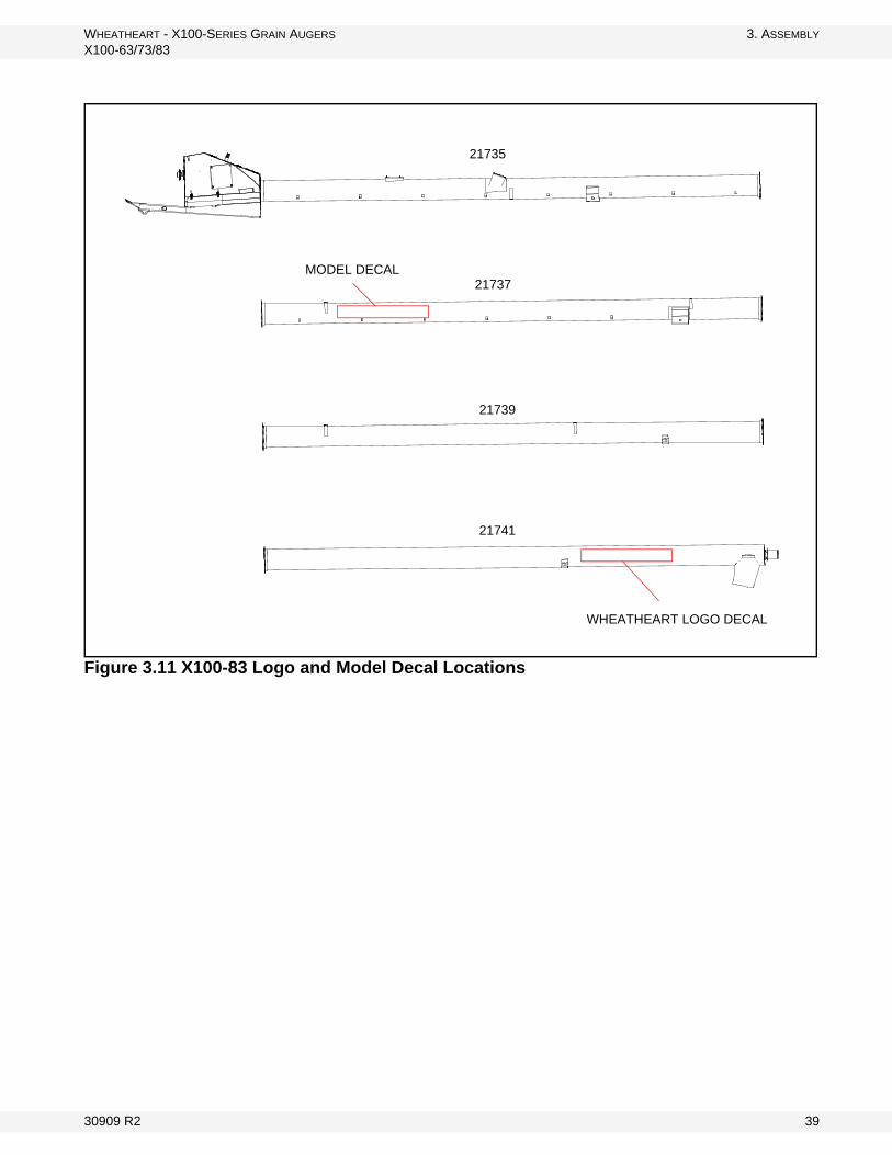
3.2.6. APPLY LOGO AND MODEL DECALS ON THE AUGER TUBES
Note: See the model-specific figures on the following page for Wheatheart logo and model decal locations.
1. Prepare surface by cleaning thoroughly with soap and water. Surface must be clean and free of dirt, grime, rust and oil. To clean oily surface, wipe with clean cloth and solvent cleaner or isopropyl alcohol.
2. Position the decal on the tube and apply masking tape along the top, creating a gate hinge. Figure A demonstrates.
3. Remove backing paper from decal 6" from the top and use the squeegee to adhere decal to the tube, as seen in Figure B. Start at the top center of the decal and work your way outward both left and right using overlapping strokes.
4. As you work your way down the decal, peel back the backing paper 6" at a time. Repeat Step 3 until the entire decal has been applied to the tube. See Figure C as an example.
5. Once the entire decal has been properly adhered to the tube, remove tape hinge from front of decal. Remove the front application tape at a sharp 180° angle.
6. Inspect the entire decal for air pockets; if found, remove them by punching a tiny hole with a pin and then squeegee the surface flat.
7. As a final process, squeegee the corners and edges of the decal to ensure proper adhesion and to prevent premature peeling.
30909 R2 37

3. ASSEMBLY WHEATHEART - X100-SERIES GRAIN AUGERS
X100-63/73/83
Figure 3.9 X100-63 Logo and Model Decal Locations
Figure 3.10 X100-73 Logo and Model Decal Locations
21729
21731
21733
WHEATHEART LOGO DECAL
MODEL DECAL
21735
21731
21733
WHEATHEART LOGO DECAL
MODEL DECAL
38 30909 R2
WHEATHEART - X100-SERIES GRAIN AUGERS 3. ASSEMBLY
X100-63/73/83
Figure 3.11 X100-83 Logo and Model Decal Locations
21735
21737
21739
21741
WHEATHEART LOGO DECAL
MODEL DECAL
30909 R2 39

3. ASSEMBLY WHEATHEART - X100-SERIES GRAIN AUGERS
X100-63/73/83
3.3. INSTALL TRUSS TOWERS
Install truss towers and truss cable attach brackets according to the configura-tions and hardware usage shown in Figures 3.12, 3.13, or 3.14 (according to specific model).
Figure 3.12 X100-63 Truss Supports
1: LOW TRUSS TOWER [4504083]2: 7/16” X 1” BOLTS [19542]3: 7/16” NUTS [19598]
11
2 2
3 3
1
1
4: TRUSS CABLE ATTACH BRACKET [18032WH]
2
2
33
4
40 30909 R2

WHEATHEART - X100-SERIES GRAIN AUGERS 3. ASSEMBLY
X100-63/73/83
Figure 3.13 X100-73 Truss Supports
Figure 3.14 X100-83 Truss Supports
1: LOW TRUSS TOWER [4504083]2: 7/16” X 1” BOLTS [19542]3: 7/16” NUTS [19598]
1
1
1
22
3 3
2 2
33
4:TRUSS CABLE ATTACH BRACKET [18032WH]
4
1: LOW TRUSS TOWER [4504083]2: HIGH TRUSS TOWER [4504174]3: 7/16” X 1” BOLTS [19542]4: 7/16” NUTS [19598]
1
1
2
3 3
3 3
4 444
5:TRUSS CABLE ATTACH BRACKET [18032WH]
5
5
30909 R2 41

3. ASSEMBLY WHEATHEART - X100-SERIES GRAIN AUGERS
X100-63/73/83
3.4. INSTALL TRUSS CABLES
Refer to Figure 3.15 and Figure 3.16, according to the specific model.
1. Leave a stand at each end of the tube sections but remove the rest of the stands and let the tube deflect under its own weight.
2. Attach an eyebolt to one end of each truss cable with two 3/8” cable clamps (4) doubling-back about 12” (0.30 m) of cable. Insert the eyebolts into the truss cable attach bracket and thread on a 1/2” locknut a short way.
3. Pull the long truss cable:• over the cable bridges• around the cable return bracket• back over the cable bridges• back to the cable anchor racket
4. Pull the short truss cable:• over the middle cable bridge• around the cable return bracket• back over the middle cable bridge• back to the cable anchor bracket
Important: The long truss cable must be installed on the outside of the middle bridge.
5. Use loosely attached 5/16” cable clamps to hold the cable in place — 2 cable clamps per cable bridge and two clamps on the cable return bracket.
Note: Do not tighten the cable clamps at this time.
6. Insert eyebolts in the opposite sides of both cable attach brackets remaining position each cable attach bracket and for each, thread on a 1/2” locknut a short way.
7. Thread the end of each truss cable through the appropriate eyebolt and pull the cable snug. Double-back the cable and secure in place with two 3/8” cable clamps as in Step 2.
Note: If there isn’t enough cable, loosen the clamps on the opposite eyebolt and adjust the cable. Retighten clamps.
8. Tighten the eyebolts on the long cable evenly to take the remaining slack out of the truss cable. Once the long cable is tightened, repeat for the short cable.
9. Check for proper side-to-side alignment and then tighten the cable clamps on the cable bridges and the cable return brackets.
42 30909 R2

WHEATHEART - X100-SERIES GRAIN AUGERS 3. ASSEMBLY
X100-63/73/83
Figure 3.15 Installing Truss Cables (X100-63, X100-73)
1
2
5
5
4
36
6
7: TRUSS CABLE ATTACH BRACKET [18032WH]
5: CABLE CLAMP (3/8”) [18990]
1: 1/2” EYEBOLT[19331]
3: LONG CABLE4: SHORT CABLE
2: 1/2” NUT
6: CABLE CLAMP (5/16”) [19333]
8: TRUSS CABLE RETURN BRACKET
36
7
8
3
4
3
4
30909 R2 43

3. ASSEMBLY WHEATHEART - X100-SERIES GRAIN AUGERS
X100-63/73/83
Figure 3.16 Installing Truss Cables (X100-83)
7: TRUSS CABLE ATTACH BRACKET [18032WH]
5: CABLE CLAMP (3/8”) [18990]
1: 1/2” EYEBOLT [19331]
3: LONG CABLE4: SHORT CABLE
2: 1/2” NUT
6: CABLE CLAMP (5/16”) [19333]
8: TRUSS CABLE RETURN BRACKET
1
55
6
6
4
3
8
3
6
2
7
3
4
3
4
44 30909 R2

WHEATHEART - X100-SERIES GRAIN AUGERS 3. ASSEMBLY
X100-63/73/83
3.5. ASSEMBLE THE FRAME
1. Ensure the workspace is clear and large enough to accommodate assembly of the auger.
2. Place the axle on the floor, supported by two 4" blocks under each side, and positioned so that the lower lift arm flanges face toward the assembly area.
3. Install lower lift arms on each side of the axle:a. Use four 3/4'' x 2'' bolts and 3/4'' locknuts to connect each lower frame arm
to respective axle end flanges.
Note: Insert a punch tool (P) in the middle hole to help align the four bolt holes.
b. Support the lower lift arms along their length with 4” blocks.
4. Install the scissor rest on the axle using four 3/8'' x 1-1/4'' bolts and 3/8'' locknuts for each tube. Ensure that the scissor rest is oriented as shown in the diagram.
Figure 3.17 Assemble the Lower Frame
WARNING
Components are heavy and create a crushing and pinching hazard if improperly handled. Be sure to use proper hoisting equipment and procedures, and ensure lifting apparatus is secure. Lockout the lifting apparatus before working around or under the raised components. Failure to do so may cause serious personal injury.
1
2
2 4
4
3
5
5
P
30909 R2 45

3. ASSEMBLY WHEATHEART - X100-SERIES GRAIN AUGERS
X100-63/73/83
Table 3.2 Assemble the Lower FrameRef Description X100‐63 X100‐73 X100‐83 Amount1 X100 Axle Assembly 21765 21765 21766 12 Lower Reach Arm 21742 21749 21753 23 X10 Transport Stand 21746 21746 21746 1
43/4" x 2" Bolt 19592 19592 19592 83/4" Locknut 19601 19601 19601 8
53/8" x 1-1/4" Bolt 19975 19975 19975 83/8" Locknut 17402 17402 17402 8
46 30909 R2

WHEATHEART - X100-SERIES GRAIN AUGERS 3. ASSEMBLY
X100-63/73/83
3.6. CONNECT THE LOWER FRAME ARMS
Note: The position of the lower frame arm connections on the axle depends on the model. For the X100-83 model the frame arms connect using the outermost bracket positions. For the X100-73 model the frame arms connect using the middle bracket positions. For the X100-63 model the frame arms connect using the innermost bracket positions.
1. Elevate the reach arms on a support stand, and place another support stand so it can be used to support the lower scissor arms as they are installed.
2. Lift, position, and connect the lower scissors one at a time. Use lower scissor attach pins to attach the narrow ends of the arms to the flanges on the axle, and secure each pin with two 1” SAE washers and two 1/4” x 1-3/4” cotter pins.
Figure 3.18 Attach Lower Scissor Arms
1
2
5
4
54
3
X100-83
X100-73
X100-63
Table 3.3 Attach Lower Scissor ArmsRef Description X100‐63 X100‐73 X100‐83 Amount1 X10 Lower Scissor - RH 21743 21751 21755 12 X10 Lower Scissor - LH 21744 21750 21754 13 Lower Scissor Attach Pin 20049 20049 20049 24 1" Rim Washer 18097 18097 18097 45 1/4" - 1-3/4" Cotter Pin 18098 18098 18098 4
30909 R2 47

3. ASSEMBLY WHEATHEART - X100-SERIES GRAIN AUGERS
X100-63/73/83
3.7. CONNECTING THE SHORT CROSS MEMBER AND UPPER SCISSORS ARMS
1. Lift, position, and connect the upper scissor to both lower scissor arms with a greased scissor pin inserted in each side, and lock the scissor pins in place with 7/16'' x 1-1/4'' bolts and nuts.
2. Lift the short cross member into place, and bolt it to the lower scissors using eight 5/8'' x 2'' bolts and 5/8'' locknuts per side.
Figure 3.19 Connecting Upper Scissors and Short Cross Member
Table 3.4 Connecting Upper Scissors and Short Cross MemberRef Description X100‐63 X100‐73 X100‐83 Amount1 X10 Short Cross member 21757 21757 21757 12 X10 Upper Scissor 21745 21752 21756 13 X10 Scissor Pin 21771 21771 21771 2
45/8" x 1-1/2" Bolt 19590 19590 19590 85/8" Locknut 19600 19600 19600 8
57/16" x 1-1/4" Bolt 18698 18698 18698 27/16" Locknut 19598 19598 19598 2
48 30909 R2

WHEATHEART - X100-SERIES GRAIN AUGERS 3. ASSEMBLY
X100-63/73/83
3.7.1. INSTALL HYDRAULIC LIFT CYLINDER
1. Position the cylinder on the cylinder lugs. The rod end of the cylinder must be attached facing downward, with the port to the right-hand side of the auger.
2. Pin the cylinder in place using 1” x 3-3/8” cylinder pin and 1” hitch clips.
Figure 3.20 Installing Lift Cylinder
7/16” X 1” BOLTS [19542]
7/16” LOCKNUTS [17593]
Port
30909 R2 49

3. ASSEMBLY WHEATHEART - X100-SERIES GRAIN AUGERS
X100-63/73/83
3.8. ASSEMBLE THE WHEEL HUB AND INSTALL TIRES
For each axle insert (X100-63/73) or extension (X100-83) and hub assembly (17013) pair:
1. Remove any dirt or paint from spindle and hub. 2. Thoroughly pack wheel bearings and cups with a good grade of bearing
grease.3. Place large bearing into hub and carefully tap in seal. 4. Slip hub onto spindle and insert small bearing.5. Tighten slotted spindle nut until hub drags slightly. Back off the nut about 1/4
turn until the hub turns freely. 6. Install cotter pin and dust cap.
Note: Installing tires may not leave you with enough clearance to position and attach undercarriage once auger tube is raised. If so, install wheels after assembly is complete.
7. Check that pressure of pre-inflated tires matches pressure indicated on tire sidewall. Mount wheels on hubs and attach with six 1/2” x 1-3/4” wheel bolts.
Figure 3.21 Wheel Hub Assembly
1/2” X 1-3/4”
SEAL
LARGE BEARING
HUB
SMALL BEARING
SLOTTED SPINDLE NUT
DUST CAP
COTTER PIN
WASHER
WHEEL BOLTS
16” WHEEL RIM
50 30909 R2

WHEATHEART - X100-SERIES GRAIN AUGERS 3. ASSEMBLY
X100-63/73/83
3.9. CONNECT THE AUGER TUBE TO THE FRAME
1. Arrange a strong sling around the auger tube. Attach the sling to a crane, block and tackle, or a front end loader, and lift the auger tube high enough to remove the stands from underneath the auger.
2. Move tube over top of the assembled frame, ensuring that the tube is centered on the scissor frame before proceeding.
3. Connect tube to the lower frame arms:a. Lift the lower frame arms to align with the lower back-arm bracket bolt
holes.
b. Secure each lower frame arm to its corresponding tube back-arm bracket with a spacer bushing, a flat washer, a 1” x 2-1/2” bolt, and a locknut.
4. Connect tube to the scissor lift:a. Adjust the tube height and frame position until the holes in the upper back-
arm brackets are aligned with the flange bolt holes at the top of the upper scissor arm.
b. Secure each side of the upper scissor arm to its corresponding tube back-arm bracket with a spacer bushing, a flat washer, a 1” x 2-1/2” bolt, and a locknut.
5. Lower the scissor lift until it rests on the transport stand.
30909 R2 51

3. ASSEMBLY WHEATHEART - X100-SERIES GRAIN AUGERS
X100-63/73/83
Figure 3.22 Connecting the Auger Tube to Frame
Table 3.5 Connecting the Auger Tube to Frame Ref Description X100-63 X100-73 X100-83 Amount1 Spacer Bushing, Short 20297 20297 20297 42 1" x 2-1/2" Bolt 28483 28483 28483 43 1" Locknut 17019 17019 17019 44 1" Flat Washer 17020 17020 17020 4
1 2
3
4
12
3
4
52 30909 R2

WHEATHEART - X100-SERIES GRAIN AUGERS 3. ASSEMBLY
X100-63/73/83
3.10. CONNECT HYDRAULIC HOSES AND BALL VALVE
Refer to the Appendix for hydraulic fitting tightening specifications.
1. Remove plugs from the hydraulic cylinder.2. Install a steel elbow fitting into the cylinder port.3. Attach the hydraulic hose to the elbow fitting on the hydraulic cylinder.4. Run the hose along the upper scissor frame and tube. 5. Secure the hydraulic hose along the top of the upper scissor and on the tube
using the welded hose clips.6. Provide slack or a loop between each secured point. 7. Bend tops of welded clips over slightly to retain hose.8. Connect ball valve to the boot using the ball valve bracket and two 1/4" x 3/4"
bolts and locknuts (see Figure 3.25).
Do not make bends in hydraulic hose too tight. The bends must have a radius of at least 4” to prevent failure of the hose.
Figure 3.23 Hydraulic Hose Cylinder Connection
Figure 3.24 Hydraulic Hose Cylinder ConnectionDescription X100-63 X100-73 X100-83 Amount
Steel Elbow 28478 28478 28478 1Hydraulic Hose Assembly 21609 21610 21611 1Ball Valve 28475 28475 28475 11/4" x 3/4" Bolts 9900800 9900800 9900800 21/4" Locknuts 28449 28449 28449 2
Note:
Important:
PRESSURE
STEELELBOW
HYDRAULIC HOSE
30909 R2 53

3. ASSEMBLY WHEATHEART - X100-SERIES GRAIN AUGERS
X100-63/73/83
Figure 3.25 Installing the Ball Valve on the Boot
1/4” X 3/4” BOLTS [9900800]AND 1/4” LOCKNUTS [28449]
54 30909 R2
WHEATHEART - X100-SERIES GRAIN AUGERS 3. ASSEMBLY
X100-63/73/83
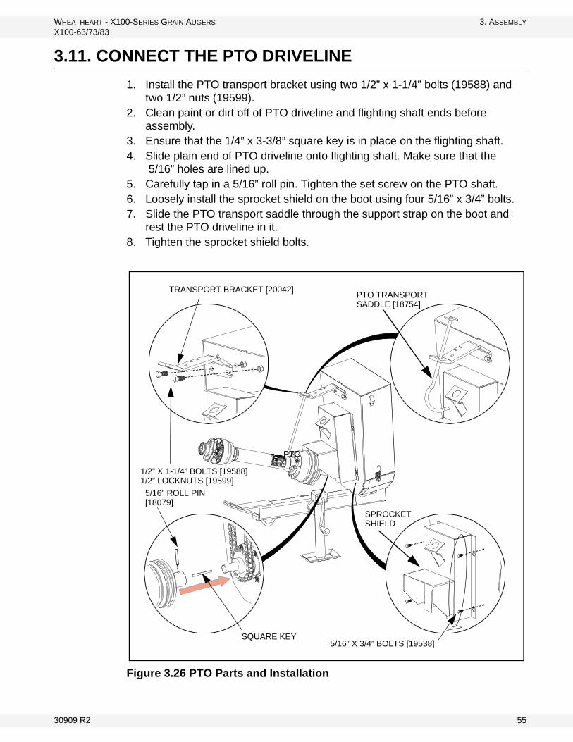
3.11. CONNECT THE PTO DRIVELINE
1. Install the PTO transport bracket using two 1/2” x 1-1/4” bolts (19588) and two 1/2” nuts (19599).
2. Clean paint or dirt off of PTO driveline and flighting shaft ends before assembly.
3. Ensure that the 1/4” x 3-3/8” square key is in place on the flighting shaft.4. Slide plain end of PTO driveline onto flighting shaft. Make sure that the
5/16” holes are lined up.5. Carefully tap in a 5/16” roll pin. Tighten the set screw on the PTO shaft.6. Loosely install the sprocket shield on the boot using four 5/16” x 3/4” bolts. 7. Slide the PTO transport saddle through the support strap on the boot and
rest the PTO driveline in it.8. Tighten the sprocket shield bolts.
Figure 3.26 PTO Parts and Installation
TRANSPORT BRACKET [20042]
1/2” X 1-1/4” BOLTS [19588]1/2” LOCKNUTS [19599]
PTO TRANSPORTSADDLE [18754]
5/16” ROLL PIN[18079]
PTO
SPROCKETSHIELD
SQUARE KEY5/16” X 3/4” BOLTS [19538]
30909 R2 55

3. ASSEMBLY WHEATHEART - X100-SERIES GRAIN AUGERS
X100-63/73/83
3.12. INSTALL LOW PROFILE INTAKE HOPPER
1. Attach the Transition to the intake hopper with two 5/8” x 1-1/2” bolts (19590) and 5/8” locknuts (19600). DO NOT over-tighten; tighten to a slightly loose fit only as these bolts act as pivot points (Figure 3.27).
Figure 3.27 Installing the Transition
2. Clean dirt and paint from inside the u-joint and flighting shaft end, grease the shaft end, then insert a Woodruff key (Figure 3.28).
3. Raise and support the hopper tube spout head on a stand about 50” high. 4. Open the service door on the Transition, then bring the tube and Transition
together guiding the flight shaft into the u-joint (Figure 3.28).5. Secure the tube to the pivot-connector on the hopper with eight
7/16” x 1” bolts (19542) and 7/16” locknuts (19598). 6. Tighten set screws on u-joints, then close and secure the service door.
WARNING
Components are heavy and create a crushing hazard if improperly handled. Be sure to use proper hoisting equipment and procedures, and ensure lifting apparatus is secure. Lockout the lifting apparatus before working around or under the raised components. Failure to do so may cause serious personal injury.
5/8” X 1-1/2” BOLTS[19590]
5/8 LOCKNUT[19600]
5/8” LOCKNUT[19600]
TRANSITION
56 30909 R2

WHEATHEART - X100-SERIES GRAIN AUGERS 3. ASSEMBLY
X100-63/73/83
7. Attach the 4 solid wheels to the 4 hopper corners with the axle pins and hairpins. There are 3 height settings (Figure 3.29) that can be used according to preference.
8. To connect the intake hopper to the auger boot, the swing head spout door must first be opened. To do so, open the spring clasps and rotate the spout door open, so that it lies down on the top of the swing tube.
9. Check that the u-joint spline and splined shaft on the lower gear box are clean, then apply a light film of grease on the splined shaft.
10. Install a rim washer (17370) on the top shaft of the lower gearbox.11. Shift the position of the hopper so that the spout head is supported above the
hopper, centred on the shaft of the gear box.12. Lower the spout head onto the boot while guiding the splined universal joint
onto the splined gearbox shaft. Once positioned, the swivel ring should be resting flat on the boot surface.
13. Install spout head spacers (29152), followed by spout-head retainers (29166), using eight 3/8” x 3/4” bolts (19540) (Figure 3.30).
14. Lubricate the universal joint and then close and secure the spout head service cover.
Important: Always keep the spout head service cover closed and secured during operation.
Figure 3.28 Connection the Flighting and Tube
50”
7/16” X 1” BOLTS[19542]
7/16” LOCKNUTS[19598]
WOODRUFF KEY[19224]
SPOUT HEAD
30909 R2 57

3. ASSEMBLY WHEATHEART - X100-SERIES GRAIN AUGERS
X100-63/73/83
Figure 3.29 Connecting the Wheels, Inspection Hatch Bar, and Hopper Cable Attach Bracket
Figure 3.30 Connecting the Spout Head to the Boot
WHEEL, WHEEL PIN, ANDHAIRCLIP
INSPECTION HATCH BAR AND HAIRCLIP
SPOUT HEAD SPACER[29152]
SPOUT HEAD RETAINER[29166]
3/8” X 3/4” BOLTS[19540]
SPOUT HEADSERVICE COVER
RIM WASHER[17370]
58 30909 R2

WHEATHEART - X100-SERIES GRAIN AUGERS 3. ASSEMBLY
X100-63/73/83
3.13. INSTALL THE HOPPER LIFT EXTENSION
X100-83 only:
1. Place the hopper lift extension onto the bracket on the lower tube as shown.2. Secure by using the 2 lift extension brackets and six 7/16” x 1-1/4” bolts and
locknuts.
Figure 3.31 Installing the Lift Extension
3.14. INSTALL HOPPER LIFT ARM AND WINCH
1. Determine which side of the auger the hopper will be operating on.
Note: Feed side of hopper must face the main auger when in transport.
2. Position the hopper lift arm on the mount bracket on top of the lower auger tube with the arm overhanging the left side of the auger (as viewed from the boot, looking toward the discharge spout).
3. Fasten the hopper lift arm assembly to the mount bracket on top of the lower auger tube with two mount pins (18074) and a hairpins (19463).
4. Install winch and winch bracket assembly to auger boot (opposite to side of hopper operation) with one mount pin and a hairpin (Figure 3.33).
5. Install the transport hook assembly to the lift arm using a 7/16” x 1-1/4” bolt (18698), 7/16” washer (17182), and 7/16” locknut (19598).
6. Thread the cable through the hopper lift arm and pull the cable to the winch.7. Wrap the cable over and around the winch spool at least three times, then
insert the cable end through the hole provided in the side of the spool and secure the end with the provided cable clamp (Figure 3.34).
30909 R2 59

3. ASSEMBLY WHEATHEART - X100-SERIES GRAIN AUGERS
X100-63/73/83
8. To place hopper into transport position, attach cable hook to hook on the hopper transition, then fully raise hopper with intake side facing main auger. Secure hopper to lift arm by connecting the safety chain (Figure 3.35) to the hopper cable attach bracket.
Figure 3.32 Installing the Lift Arm
Figure 3.33 Connecting Manual Winch to the Boot
PIN [18074]
HAIRPIN
WINCH ASSEMBLY
BOOT WINCH BRACKET
[19463]
60 30909 R2

WHEATHEART - X100-SERIES GRAIN AUGERS 3. ASSEMBLY
X100-63/73/83
Figure 3.34 Connecting Winch Cable to Spool
Figure 3.35 Transport Position, Safety Chain and Winch Hook
CABLE CLAMP
WINCH CABLE
TRANSPORT CHAINAND HOOK
WINCH CHAINAND HOOK
30909 R2 61

3. ASSEMBLY WHEATHEART - X100-SERIES GRAIN AUGERS
X100-63/73/83
If you want to change the side of intake feed hopper operation:
a. Raise auger hitch jack and disconnect from tractor.
b. Swing intake feed hopper to opposite side of auger.
c. Reverse the position of the hopper lift arm assembly.
d. Position the winch upside down on the other side of the boot.
e. Reconnect to tractor.
Figure 3.36 Positioning winch on the other side of the boot
3.15. INSTALL THE HITCH JACK
The jack is attached to the auger with a pin at the pivot point. To install:
1. Elevate the auger boot (intake end) approximately 2’ (5.08 cm) with a front-end loader and sling, and install the jack in a vertical position. Secure with supplied pin.
2. Place a board beneath the jack before setting it on the ground, then lower the auger until the jack is seated. Remove front-end loader from auger.
Note: Jack can be rotated 90° for transport or operation.
HAIRPINBOOT WINCH BRACKET
WINCH ASSEMBLY
PIN
WARNING
Jack is designed for raising or lowering auger hitch only.
Do not get on or beneath auger while supported by or while jack is being operated.
62 30909 R2

WHEATHEART - X100-SERIES GRAIN AUGERS 3. ASSEMBLY
X100-63/73/83
3.16. INSTALL THE PLASTIC MANUAL CONTAINER
Mount the plastic manual holder directly to the boot (as shown below) using three #14 x 5/8” self-tapping screws (19274).
Figure 3.37 Installing the Plastic Manual Container
30909 R2 63
3. ASSEMBLY WHEATHEART - X100-SERIES GRAIN AUGERS
X100-63/73/83
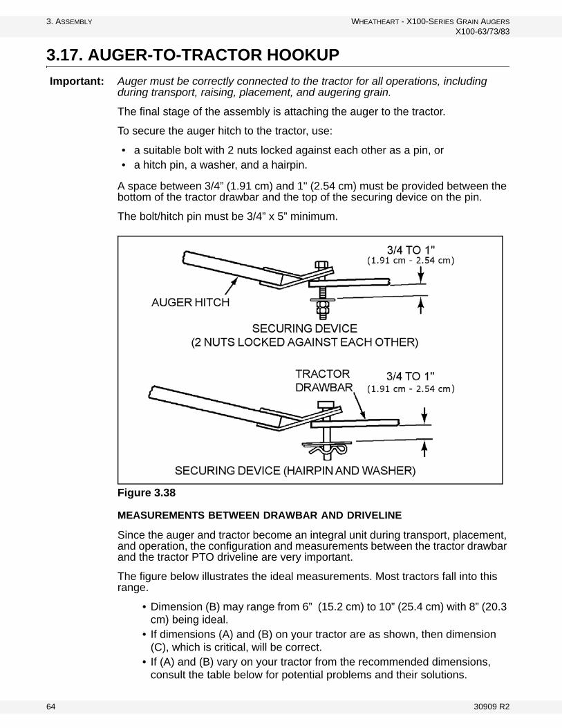
3.17. AUGER-TO-TRACTOR HOOKUP Important: Auger must be correctly connected to the tractor for all operations, including
during transport, raising, placement, and augering grain.
The final stage of the assembly is attaching the auger to the tractor.
To secure the auger hitch to the tractor, use:
• a suitable bolt with 2 nuts locked against each other as a pin, or • a hitch pin, a washer, and a hairpin.
A space between 3/4” (1.91 cm) and 1" (2.54 cm) must be provided between the bottom of the tractor drawbar and the top of the securing device on the pin.
The bolt/hitch pin must be 3/4” x 5” minimum.
Figure 3.38
MEASUREMENTS BETWEEN DRAWBAR AND DRIVELINE
Since the auger and tractor become an integral unit during transport, placement, and operation, the configuration and measurements between the tractor drawbar and the tractor PTO driveline are very important.
The figure below illustrates the ideal measurements. Most tractors fall into this range.
• Dimension (B) may range from 6” (15.2 cm) to 10” (25.4 cm) with 8” (20.3 cm) being ideal.
• If dimensions (A) and (B) on your tractor are as shown, then dimension (C), which is critical, will be correct.
• If (A) and (B) vary on your tractor from the recommended dimensions, consult the table below for potential problems and their solutions.
64 30909 R2

WHEATHEART - X100-SERIES GRAIN AUGERS 3. ASSEMBLY
X100-63/73/83
Figure 3.39 Measurements Between Drawbar and PTO Driveline
MEASUREMENT PROBLEM SOLUTIONIf (A) is less than 14” (35.6 cm) (C) will be less than the recom-mended 34-1/2” to 36-1/2” (87.6 cm to 92.7 cm)
• The PTO driveline will bottom out when auger is in raised position.
• This will cause damage to the PTO driveline, the bearing, or the boot housing.
• Pull out or lengthen the trac-tor drawbar as needed to make (C) 34-1/2” to 36-1/2” (87.6 cm to 92.7 cm) when the auger is in full down posi-tion.
If (A) is more than 14” (35.6 cm) (C) may be more than the recom-mended 34-1/2” to 36-1/2” (87.6 cm to 92.7 cm)
• The PTO driveline will separate from the auger in the lowered position.
• This will cause damage to equipment and/or injury to personnel.
• Shorten distance (C) to the recommended 34-1/2” to 36-1/2” (87.6 cm to 92.7 cm) by attaching hitch to tractor drawbar at a point closer to the tractor PTO shaft.
If (B) is more than 10” (25.4 cm) (C) (between tractor PTO shaft and auger input shaft) short-ens more quickly when auger is being raised
• The u-joint angle on the PTO driveline will be too severe in the raised position.
• The PTO driveline will bottom out before auger is fully raised.
• This will cause damage to the PTO driveline, flight shaft, bearing, and boot.
• Raise the tractor drawbar until dimension (B) is within the recommended 6” to 10” (15.2 cm - 25.4 cm).
A: 14” (35.6 CM)B: 6” - 10” (15.2 CM - 25.5 CM)C: 34-1/2” - 36-1/2” (87.6 CM - 92.7 CM)
30909 R2 65

3. ASSEMBLY WHEATHEART - X100-SERIES GRAIN AUGERS
X100-63/73/83
66 30909 R2

WHEATHEART - X100-SERIES GRAIN AUGERS 4. TRANSPORT AND PLACEMENT
X100-63/73/83
4. Transport and Placement
This auger is designed to be transported and operated without unhitching unit from tractor.
4.1. TRANSPORT PROCEDURE
1. Place auger in full down position.
• Disconnect PTO driveline from tractor.
2. Position and secure hitch pin and safety chain. Place safety chain through clevis welded to auger hitch tube and bolt together before attaching to tractor.
3. Place the intake hopper into transport position (see Figure 4.2):a. Attach the winch cable hook to the appropriate hopper lifting point.
b. Fully raise the hopper with intake side facing towards the main auger tube.
c. Secure the hopper with the transport chain and hook.
WARNING Before continuing, ensure you have read and understand the relevant information in the safety section. Safety information is provided to help prevent serious injury, death, or property damage.
CAUTION
Always tow auger in the lowered position.
Disconnect PTO driveline from tractor for transport and placement.
Figure 4.1
30909 R2 67

4. TRANSPORT AND PLACEMENT WHEATHEART - X100-SERIES GRAIN AUGERS
X100-63/73/83
Note: Do not operate auger with intake hopper in transport position. This will damage the u-joint.
4. Place swivel jack (on side of hitch) in transport position and lock.
Figure 4.2 Hopper in Transport Position
Important: Intake feed side of hopper must face main auger when in transport (Figure 4.2)
5. Clear all untrained personnel from transport zone.
CAUTION
If auger wheels are partially or fully buried in snow or grain, failure to clear the area around the wheels before moving may cause damage to the auger or result in serious injury.
WINCH CABLEAND HOOK
TRANSPORT CHAIN
AND HOOK
WARNING
Beware of overhead obstructions and electrical wires and devices. See “Specifications” on page 101 for minimum transport heights.
68 30909 R2

WHEATHEART - X100-SERIES GRAIN AUGERS 4. TRANSPORT AND PLACEMENT
X100-63/73/83
4.2. PLACEMENT PROCEDURE
1. Disconnect PTO driveline from tractor and secure in transport saddle.
2. Ensure that tractor and auger are securely hitched together. Important: Use a type of hitch pin (see Auger / Tractor Hookup section) that will not allow auger to separate from towing vehicle.
Important: 3. Disconnect the safety chain from the intake hopper.4. Before connecting hose, ensure that the quick-connect coupler on auger and
tractor is clean and free of dirt by wiping with a cloth.
5. Connect hydraulic hoses, ensure connections are tight. Check for leaks, binding, flattening, kinks, or wear.
6. If the auger must be raised for positioning:a. Check that valve on hose to lift cylinder is open.
b. Raise auger to the desired height.
c. Close hose valve (after auger is positioned).
• The X100-83 auger features a hydraulic lift system that only needs a small amount of hydraulic oil to raise the auger. This is done by pumping oil into and out of the upper chamber of the cylinder as the auger is raised and
WARNING
Auger must be hooked up to tractor for all operations, including transport, raising, placement, and augering grain.
NOTICE
When positioning the auger, the PTO driveline must be disconnected from the tractor and placed in the transport saddle to prevent damage to auger and PTO driveline.
CAUTION
Dirt in the hydraulic system can damage the cylinder o-rings, causing leakage and the possible failure of the system and personal injury.
NOTICE
Replacement hose and hose ends must have a minimum strength of 2500 psi (17200 kPa) working pressure.
30909 R2 69

4. TRANSPORT AND PLACEMENT WHEATHEART - X100-SERIES GRAIN AUGERS
X100-63/73/83
lowered. For this system to work, the tractor must be running and the down lever must be fully engaged as auger is lowered.
.
7. Move the auger into working position slowly, making sure that there is no one in the hazard zone. Do not unhitch and attempt to move auger by hand.
8. Once auger is in position, chock wheels on both sides and apply the park brake on the tractor (or chock its wheels as well) to prevent movement during operation.
9. Fully lower hopper to the ground and remove lift cable from the hopper. See “Lowering & Completion” on page 82 for the correct lowering procedure.
NOTICE
The hydraulic cylinders are shipped without oil and must be charged with oil before auger is put into operation. See the appendix for charging instructions.
WARNING
Fluid leaks in the hydraulic cylinder or hose will allow auger to lower inadvertently.
Repair all leaks and breaks immediately.
CAUTION
If hose valve remains open, a loss of hydraulic pressure within in the tractor system will allow the auger to lower inadvertently, damaging the equipment and causing personal injury.
WARNING
Do not disconnect coupler under pressure. Relieve pressure and then disconnect.
WARNING
Never attempt to increase height of auger by positioning wheels on lumber, blocks, or by any other means. To do so will result in damage to equipment and/or serious injury.
70 30909 R2

WHEATHEART - X100-SERIES GRAIN AUGERS 4. TRANSPORT AND PLACEMENT
X100-63/73/83
AXLE EXTENSION PROCEDURE FOR X100-83 AUGER ONLY:
Place auger on level ground before attempting to extend or retract the axle extensions. Auger must be attached to tractor at all times.
Once the auger is located, you may begin the axle extension process.
1. Using the jack supplied, insert it into one of the jack lugs located on one end of axle (Figure 4.3). Jack must be secured to jack lug using pin (attached to jack).
2. Raise one side at a time. Ensure that the jack is vertical. Turn the crank to start raising the jack. Raise one side of the axle until the tire clears the ground.
3. Remove the axle pin from the axle and slide the axle outwards 16” until the second set of holes line up (Figure 4.3). Reinsert the pin and secure with snap pin. Lower the jack.
4. Repeat the process on the other side of the axle to extend the other side.Note: Use the same procedure, in reverse, to retract the axle.
WARNING
Do not raise the auger unless the axles are in the extended position.
Do not transport the auger unless the axles are in the retracted position.
Figure 4.3
JACK LUG
AXLE PIN
SNAP PIN
30909 R2 71

4. TRANSPORT AND PLACEMENT WHEATHEART - X100-SERIES GRAIN AUGERS
X100-63/73/83
Figure 4.4 Auger Placement (Direct PTO Drive)
4.3. POSITIONING TRACTOR FOR RIGHT-ANGLE DRIVE OPERATION
1. Use the tractor to position the auger at the bin, as described in “Placement Procedure” on page 69, ensuring that the auger wheels are securely chocked, and that the scissor lift valve is closed.
2. Position hitch jack with board underneath, then raise auger hitch slightly.3. Relieve pressure in hydraulic hose, then disconnect from tractor and place in
the auger’s hose rack.4. Remove safety chain and hitch pin, then move tractor.5. Attach the support leg as shown in Figure 4.5, and secure with pin and
hairclip.6. Place board under support leg if needed, then lower hitch jack until auger
intake weight is supported with the support leg. Place hitch jack into transport position.
72 30909 R2

WHEATHEART - X100-SERIES GRAIN AUGERS 4. TRANSPORT AND PLACEMENT
X100-63/73/83
Figure 4.5 Right Angle Drive Support Leg Working (left) and Storage Positions (right)
7. Tractor Hookup to Right Angle Drivei. Position tractor at right angle to auger intake; chock tractor wheels and
apply brakes.
ii. Securely connect the non-separable PTO driveline to tractor (maximum rpm is 540). Make sure all guards and master guards are in place.
iii. Do not exceed the maximum PTO operating length of 80” (2.03 m) or a maximum angularity of 15° from the ideal 90° drive angle.
Figure 4.6 Tractor Position for Right Angle PTO Drive (Left Side Drive Con-figuration)
30909 R2 73

4. TRANSPORT AND PLACEMENT WHEATHEART - X100-SERIES GRAIN AUGERS
X100-63/73/83
4.4. LOWERING THE AUGER
To lower the auger:
1. Reconnect hose coupler to tractor, if disconnected.2. Disconnect PTO driveline from tractor before lowering.3. Ensure that area beneath auger is clear.4. Open hose valve.5. Open tractor valve, feathering the control to prevent too rapid a descent.
Important: Once valves are opened, auger lowers by gravity. As the auger nears the full down position, the rate of descent will increase. Do not operate with tractor valve fully open. See “Lowering & Completion” on page 82 for more details.
74 30909 R2

WHEATHEART - X100-SERIES GRAIN AUGERS 5. OPERATION
X100-63/73/83
5. Operation
5.1. OPERATOR CONTROLS
Figure 5.1 shows the hydraulic shut-off valve for the main auger tube hydraulic lift cylinders.
Figure 5.2 and Figure 5.3 (respectively) show hydraulic winch and manual winch controls for lifting and lowering the hopper to and from transport position.
For locations for PTO and hydraulic supply controls, please refer to the operating manual for the attached tractor.
Figure 5.1 Main Auger Tube Lift Shut-off Valve
Figure 5.2 Hydraulic Hopper Winch Control (Optional)
WARNING Before continuing, ensure you have read and understand the relevant information in the safety section. Safety information is provided to help prevent serious injury, death, or property damage.
30909 R2 75

5. OPERATION WHEATHEART - X100-SERIES GRAIN AUGERS
X100-63/73/83
Figure 5.3 Manual Hopper Winch
76 30909 R2

WHEATHEART - X100-SERIES GRAIN AUGERS 5. OPERATION
X100-63/73/83
5.2. PRE-OPERATION
5.2.1. CHECKLIST
• Tighten all fasteners.• Adjust and/or lubricate boot chain and hopper chain.• Ensure auger rotates freely.• Check that tire pressure is within the manufacturer’s specification.• Ensure wheel bolt torque is within specification.• Check hopper winch and lift cable for damage (fraying, kinking, unraveling).
Replace as required. • Ensure cable anchor on the winch drum is tight.• Check gearbox oil levels.• Grease and clean machine if needed.• Ensure hydraulic system is functioning, is free of leaks, and the hoses are not
pinched or kinked.• Check that truss cables are free from damage (fraying, kinking, unraveling).
Cables must be tight and properly adjusted for proper auger tube alignment.• Ensure PTO shaft is properly installed.• Ensure intake area and discharge spout are free of obstructions.• Ensure tractor and auger are in line or as close to being in line as possible.• Ensure tractor park brake is engaged and/or wheels are chocked.• Ensure that axles are extended during auger operation (X100-83 only).• Ensure cable clamps are secure.• Ensure that tube alignment is straight.• Ensure appropriate maintenance has been performed.• Know the procedure for safe shut-down of the auger in case of emergency.
30909 R2 77

5. OPERATION WHEATHEART - X100-SERIES GRAIN AUGERS
X100-63/73/83
5.2.2. PTO DRIVE
Correct operation of the auger requires pre-inspection of the drive system, operator knowledge on how to shut down the system, and a general monitoring of the system during operation.
GENERAL INFORMATION
Before starting the auger, ensure that:
• The PTO driveline is securely attached to the auger shaft and to the tractor.• The PTO driveline rotating shield is in place and in good working order. • The PTO does not exceed the maximum operating angle of 15°.• All safety shields are in place and secure on both the tractor and the auger.• The PTO drive on the tractor is in the off position before starting the tractor.• The auger-to-tractor PTO hookup distances are set as specified in the decal
on the PTO shield of the auger.• Everyone is clear of the PTO hazard area.
Note: If shear bolt in the PTO driveline fails, shut down and lock out the tractor to replace the bolt. Use a 5/16” x 1” GR 8 bolt. Ensure the shear point is through the shank of the bolt, not the threads.
LOCKOUT
1. Shut down the tractor and remove the ignition key.2. If step 1 is not possible, remove the PTO driveline from the tractor.
5.2.3. HYDRAULICS
X100 series grain augers are equipped with a standard 3/8” Pioneer Coupler used to connect the auger hydraulic system(s) to the tractor.
Before using the hydraulics, ensure that:
• The quick connect couplers on both the auger and the tractor are clean and free of dirt. Wipe the couplers with a clean, dry cloth.
• The hydraulic hoses are properly connected and secured; are free of leaks, wear, and binding; and are routed away from moving parts.
• Hydraulic pressure has been relieved prior to disconnecting.
NOTICE
When positioning the auger, the PTO driveline must be disconnected from the tractor and placed in the transport saddle to prevent damage to auger and PTO driveline.
78 30909 R2

WHEATHEART - X100-SERIES GRAIN AUGERS 5. OPERATION
X100-63/73/83
5.3. OPERATING PROCEDURES
5.3.1. INITIAL START-UP
BREAK IN
Your auger does not require an elaborate break-in. However, following a few simple tips during the initial operation can add to the reliability and life of your machine.
If any unusual noises or vibrations are encountered, determine the source, shut the auger off, lock out the power source, and adjust. If unsure of the problem or procedure, contact your local Wheatheart dealer.
Important: When starting the auger for the first time, be prepared for an emergency shutdown in case of excessive vibration or noise.
1. Ensure that you have completed the checklist on page 77.2. If everything is satisfactory, prepare for a 60 minute operation at half speed.3. Ensure that the intake hopper is correctly positioned.4. Ensure that the PTO drive on the tractor is in the OFF position.5. Start the tractor and idle at low rpm. Slowly engage the PTO drive.
Note: The auger may run rough until the tube is polished.
6. Gradually begin feeding grain into the hopper, bringing the auger speed up to about 300 rpm. Do not overfeed the hopper on initial loads; keep the feed of grain at about half capacity.
7. After the auger tube is polished and runs fairly smoothly, proceed to unload at full speed of 540 rpm.
8. Upon completion of the initial run, slow the auger down. Stop the auger when it is empty of grain.
DANGER
Rotating Auger Hazard
Contact with rotating flighting will result in amputation or severe laceration.
DO NOT operate with guards removed or modified.
Keep hands and feet away from rotating auger.
Tie up long hair and remove jewelry.
DO NOT wear loose-fitting clothing or items that could become caught.
Shut off and lock out the power source before unplugging or cleaning.
30909 R2 79

5. OPERATION WHEATHEART - X100-SERIES GRAIN AUGERS
X100-63/73/83
9. Lock out the tractor and conduct a complete inspection of the auger following the checklist on page 77.
Important: After the initial start-up and inspection, the auger should be shut down and inspected at least 3 more times during the first 10 hours of operation.
5.3.2. NORMAL START
1. Complete the checklist on page 77.2. Place the intake hopper in its working position. 3. Make sure the PTO drive is in the off position when starting the tractor.4. Engage the PTO with the tractor idling to prevent unneeded stress on the
drive components and shear bolts. 5. If everything is operating normally, start running grain through the auger and
bring the auger up to speed. Maintain a speed of 300–540 rpm for maximum efficiency and to reduce the chance of plugging.
• Monitor the auger during operation for abnormal noises or vibrations.
NOTICE
Do not run an empty auger at high speed; this results in excessive wear. Do not exceed 540 RPM.
NOTICE
Foreign objects can damage the auger. Remove any obstructions from the intake and discharge areas before operating the unit.
DANGER
Rotating Flighting Hazard!
To prevent death or serious injury:• Keep away from rotating auger flighting.• Do not remove or modify auger flighting
guards, doors, or covers. Keep in good working order. Have replaced if damaged.
• Do not operate the auger without all guards, doors, and covers in place.
• Never touch the auger flighting. Use a stick or other tool to remove an obstruc-tion or clean out.
• Shut off and lock out power to adjust, ser-vice, or clean.
80 30909 R2

WHEATHEART - X100-SERIES GRAIN AUGERS 5. OPERATION
X100-63/73/83
• If grain overflows through safety discharge door, then the auger is loaded beyond its capacity; reduce volume of feed going into intake hopper. Remem-ber, auger capacity will decrease as the auger’s angle increases.
5.3.3. NORMAL SHUTDOWN
1. Near the end of the load, reduce the feed of grain and decrease the auger speed where possible.
2. Run the auger until the tube is empty.3. When the auger is clear of grain, disengage the PTO.4. Shut down and lock out the power source.
USE OF GRAIN SPREADERS: Many grain spreaders cannot handle the large capacity of some augers. Some augers plug, causing damage to the flighting and other drive components. This type of damage is not covered by warranty. Hints on how to avoid this...
• Make sure spreader is turned on.• Center auger spout on spreader.• Get a larger spreader, if available.• Remove the spreader.• Do not lower auger spout into spreader.• Suspend the spreader from bin ceiling leaving extra room for excess
grain to flow over the spreader.
BIN LEVEL INDICATORS: These augers are fast and bins fill up quickly. A full bin will cause auger to plug, which can damage the flighting and other drive components. Installing quality grain-level indicators on your bins will allow you to monitor bin filling and help prevent damage to your auger.
NOTICE
Prolonged operation of an empty auger will cause unnecessary wear.
30909 R2 81

5. OPERATION WHEATHEART - X100-SERIES GRAIN AUGERS
X100-63/73/83
5.3.4. EMERGENCY STOP / FULL-TUBE RESTART
Although it is recommended that the machine be emptied before stopping, in an emergency situation:
1. Stop or shut down the power source immediately.2. Stop the flow of material (if applicable).3. Correct the emergency before resuming work.
The tube may be filled with material if the machine is shut down inadvertently or for an emergency. It is recommended that you restart with the following procedure:
4. With the power source locked out, remove as much of the grain as possible from the tube and intake using a piece of wood, vacuum cleaner, or other tool. Do not use your hands.
5. If cleanout covers or safety doors have been opened or removed, close or replace them before restarting the unit.
6. Start the tractor and engage the PTO with the tractor idling.
7. Once the auger has been started, you may resume normal operation.
5.3.5. LOWERING & COMPLETION
1. Run the unit to clean out the majority of the grain from the main auger tube, boot, and hopper.
2. Turn off the tractor, and lock out the tractor power source (Refer to page 78 for procedure).
3. Disconnect the PTO driveline, and raise the intake hopper off the ground.4. Reconnect hose coupler to tractor, if disconnected.5. Remove all supports and chocks.6. Move auger away from the bin, and ensure that there is nothing under the
auger that would make contact when the auger tube is lowered.7. Open the main auger tube lift valve on the boot.8. Open the tractor supply valve for the auger, and feather between on and off
to make sure that the auger tube lowers slowly.• For the X100-83 auger, the tractor must be running while the auger is
being lowered.
NOTICE
Always engage PTO with tractor engine idling. Engaging PTO at high engine speed will result in equipment damage.
82 30909 R2

WHEATHEART - X100-SERIES GRAIN AUGERS 5. OPERATION
X100-63/73/83
• Once valves are open, auger lowers by gravity. As the auger nears the full down position, the rate of descent increases. Do not operate with tractor valve fully open.
9. If necessary, open the clean-out door on the boot and manually clean out grain using a piece of wood, vacuum cleaner, or other tool. Do not use your hands. Replace the clean-out cover.
10. Lift the intake feed hopper into transport position, and secure it with the safety chain.
WARNING
Do not leave auger in raised position when not in use. Auger could drop rapidly due to a cable break.
30909 R2 83

5. OPERATION WHEATHEART - X100-SERIES GRAIN AUGERS
X100-63/73/83
5.3.6. REVERSER OPERATION
The following procedures are a supplement to the instructions that begin in “Operating Procedures” on page 79. Read and understand all instructions before operating auger.
Figure 5.4 Forward and Reverse PTO Positions (540 RPM PTO Reverser)
Before Operating in the Normal Forward Mode:
1. The stub spline on the PTO driveline must be inserted into the Forward spline coupler (see Figure 5.4 and ) and securely locked into place.
2. Make certain the clean out cover is secured into place on the boot before operating.
3. The PTO drive control on the tractor must be in the off position before starting tractor and the PTO hazard area is clear of all bystanders.
Note: All safety shields must be in place before operating.
CAUTION
Shut down and lock out all power before emptying boot and power before changing to forward or reverse modes.
Ensure that PTO driveline is securely attached before operating. Keep body, hair, and clothing away from all moving parts including PTO driveline.
Do not exceed reverse operating speed of 100 RPM. Do not exceed forward operating speed of 540 RPM.
ReversePosition
ForwardPosition
84 30909 R2

WHEATHEART - X100-SERIES GRAIN AUGERS 5. OPERATION
X100-63/73/83
To Operate in the Reverse Mode:
1. Insert the stub spline on the PTO driveline into the Reverse spline coupler (see Figure 5.4), making certain it is securely locked into place.
2. Remove clean out cover before operating in reverse mode.
3. Operate auger slowly in reverse for a short period of time. Do not exceed 100 RPM.
4. When boot is nearly full, shut off and lock out power, then clean out grain from boot using a stick. Do not use hands. Repeat above procedure as needed.
Important: Reversing is intended to assist in clean out of auger. It is not designed to unplug auger. When operating in the reverse mode, auger must be monitored to prevent boot from overfilling. Excessive back pressure will cause extensive damage to the auger which is not covered by warranty.
Note: For transport or placement of auger, hook up auger to tractor with appropriate hitch pin and safety chain, and connect hydraulic lift hose as per manual instruc-tions.
DANGER
Rotating PTO Driveline Hazard!
Make certain the driveline shields turn freely on driveline.
Make certain the driveline is securely attached at both ends.
Do not exceed operating speed of 540 rpm.
Keep u-joint angles small and equal. Do not exceed maximum recommended length.
Failure to heed will result in serious injury or death.
30909 R2 85

5. OPERATION WHEATHEART - X100-SERIES GRAIN AUGERS
X100-63/73/83
86 30909 R2

WHEATHEART - X100-SERIES GRAIN AUGERS 6. MAINTENANCE AND STORAGE
X100-63/73/83
6. Maintenance and Storage
6.1. MAINTENANCE INTERVALS
For details of service, refer to Section 6.3.
NOTICE
Do not modify equipment.
Unauthorized modification may impair the function or safety of the equipment, could affect the life of the equipment, and will void your warranty.
WARNING Before continuing, ensure you have read and understand the relevant information in the safety section. Safety information is provided to help prevent serious injury, death, or property damage.
SECTION DAILY (8000 BU)
PERIODICALLY (40,000 BU)
BEFORE STORAGE
AFTER STORAGE
3-5 YEARS(DEPENDING ON USE)
VISUALLY INSPECT THE UNIT 6.3.1. Y - Y - -INSPECT HYDRAULIC HOSE AND COUPLER
6.3.2. Y - - - -
GREASE MACHINE 6.3.3. Y - Y - -INSPECT HOPPER LIFT CABLE
6.3.4. - Y - - -
SERVICE WINCH AND PULLEYS
6.3.5. - Y - - -
SERVICE SWING TUBE COUPLER CHAIN
6.3.6. - Y - - -
SERVICE BOOT AND HOPPER CHAIN DRIVE
6.3.7. - Y - - -
CHECK UPPER/LOWER GEARBOX OIL LEVEL
6.3.8. - Y - - -
CLEAN MACHINE 6.3.9. - - Y - -CHECK TIRE PRESSURE 6.3.10. - - Y Y -REPACK WHEEL BEARINGS 6.3.11. - - - - YTIGHTEN WHEEL BOLTS 6.3.12. - - - Y -SERVICE TRUSS CABLES 6.3.13. - - - Y -CHANGE UPPER/LOWER GEARBOX OIL
6.3.14. - - - - Y
30909 R2 87

6. MAINTENANCE AND STORAGE WHEATHEART - X100-SERIES GRAIN AUGERS
X100-63/73/83
6.2. FLUIDS AND LUBRICANTS
GEAR OIL
Use SAE approved 90W or equivalent gear oil.
GREASE
Use SAE multi-purpose high-temperature grease with extreme pressure (EP) performance or SAE multi-purpose lithium-based grease.
6.3. MAINTENANCE PROCEDURES
6.3.1. VISUAL INSPECTION
Before beginning visual inspection, check auger wheels and ensure that all operators are aware of safety procedures.
When inspecting, look for possible defects and for the following:
• Be sure all guards are in place, functioning, and not damaged.• Make sure access, service, and cleanout covers are in place and secure.• Check that all hardware is in place and secure.• Inspect hydraulic hoses and fittings for leaks and wear. Fix or replace
where necessary.• Inspect around the machine for evidence of hydraulic leaks.• Examine flighting for damage or unusual wear.• Inspect the truss cables for proper tension and possible damage such as
fraying, kinking, or unwinding.• Inspect hopper winch cable for fraying, kinking, unwinding, or other possi-
ble damage.• Examine tires for gashes, uneven wear, or loss of air pressure.• Be sure all safety decals are in place and legible.• Check the PTO shield & replace if damaged.
88 30909 R2

WHEATHEART - X100-SERIES GRAIN AUGERS 6. MAINTENANCE AND STORAGE
X100-63/73/83
6.3.2. HYDRAULIC HOSE AND COUPLER INSPECTION
Using a piece of cardboard or wood, run it along the length of the hose and around all fittings. Replace the hose or tighten/replace the fitting if a leak is found.
6.3.3. MACHINE GREASING
Important: Most original equipment bearings used are sealed units that do not accept grease.
There are 13 grease fittings on the machine (shown in Figure 6.2 and Figure 6.1):
• 5 on the PTO (Figure 6.1)• 6 on the intake hopper, u-joints and bearings (Figure 6.2) • 1 at the upper flighting bearing (Figure 6.3)• 1 at the u-joint between gearboxes (Figure 6.4)• 1 at the lower flighting bearing (Figure 6.4)
WARNING
High-pressure hydraulic fluid!
Escaping oil under pressure can penetrate the skin and cause serious injury.• Relieve pressure on system before repair-
ing, adjusting, or disconnecting.• Keep connections tight and components
in good repair.• Use a piece of wood or cardboard when
searching for leaks. DO NOT use your hand.
• Seek medical attention immediately if ANY hydraulic fluid penetrates your skin.
NOTICE
Replacement hose and hose ends must have a minimum strength of 2500 psi (17200 kPa) working pressure.
30909 R2 89

6. MAINTENANCE AND STORAGE WHEATHEART - X100-SERIES GRAIN AUGERS
X100-63/73/83
Figure 6.1 PTO Grease Fitting Locations
Figure 6.2 Hopper Grease Points
G
90 30909 R2

WHEATHEART - X100-SERIES GRAIN AUGERS 6. MAINTENANCE AND STORAGE
X100-63/73/83
Figure 6.3 Upper Flight Bearing Grease Point
Figure 6.4 Boot Grease Points
30909 R2 91

6. MAINTENANCE AND STORAGE WHEATHEART - X100-SERIES GRAIN AUGERS
X100-63/73/83
To grease:
1. Use SAE multi-purpose high-temperature grease with extreme pressure (EP) performance or SAE multi-purpose lithium-based grease.
2. Use a hand-held grease gun only.3. Wipe grease fitting with a clean cloth before greasing to avoid injecting dirt
and grit.4. If a fitting will not take grease, remove and clean thoroughly. Also clean
lubricant passageway. Replace fitting if necessary.5. Replace and repair broken fittings immediately.
6.3.4. HOPPER LIFT CABLE INSPECTION
Check the cable for damage such as fraying, kinking, or unwinding. Replace if damaged.
To replace:
1. Unwind the winch drum and remove the cable clamps.2. Free the cable from the winch and pulleys.3. Remove the cable clamps that secure the hook in place.4. Reverse the above steps to install the new cable.
6.3.5. WINCH AND PULLEY SERVICING
• Ensure the cable is slack before servicing the winch.• Check to make sure cable clamps are secure.• Keep a film of grease on the gears. Occasionally oil the bushings, drum shaft,
and ratchet.• Oil cable pulleys as needed (Figure 6.5)
92 30909 R2

WHEATHEART - X100-SERIES GRAIN AUGERS 6. MAINTENANCE AND STORAGE
X100-63/73/83
Figure 6.5 Cable Pulleys
6.3.6. SWING TUBE COUPLER CHAIN SERVICING
1. Remove any accumulated debris with a cloth or a soft wire brush.2. Inspect the power transfer chain for wear.3. Lightly oil the chain.
Figure 6.6 Swing Tube Coupler Chain
CABLE PULLEYS
SWING TUBE COUPLER CHAIN
30909 R2 93

6. MAINTENANCE AND STORAGE WHEATHEART - X100-SERIES GRAIN AUGERS
X100-63/73/83
6.3.7. BOOT AND HOPPER CHAIN DRIVE SERVICING
1. Remove chain cover plate from the boot or hopper.2. Check chain slack.
• Chain slack is checked at the midpoint of the longest span. It should be no more than 1/4” (6 mm).
Note: The Hopper has 2 chains, 1 for each flighting.
3. Adjust the chain slack.a. For the Boot: loosen the 4 bolts of the lower bearing and adjust the chain
slack (Figure 6.7) before re-tightening the bolts.
Figure 6.7 Boot Chain Drive
If the chain can’t be tightened enough, remove a link from the chain. If the chain will not fit with one link removed, add a half link to the chain and replace.
DANGER
Rotating parts hazard:• Fingers, hands, feet, hair, clothing, and
accessories can become caught or drawn into the pinch point.
• Shut off and disable power source before adjusting or servicing.
• DO NOT operate with guards removed or modified.
• Keep away from rotating parts.• Tie up long hair and remove jewelry.• DO NOT wear loose-fitting clothing or
items that could become caught.
Note:
94 30909 R2

WHEATHEART - X100-SERIES GRAIN AUGERS 6. MAINTENANCE AND STORAGE
X100-63/73/83
b. For the Hopper: loosen the 2 bolts of the flighting bearing on the side that needs adjustment and set the chain slack (Figure 6.8).
c. Ensure that the chain tension idler bolt is tightened to 120 ft-lb using a recently calibrated torque wrench.
Figure 6.8 Hopper Chain Drive
4. Lightly oil the chain.
6.3.8. GEARBOX OIL LEVEL
ACCESSING GEARBOX
Upper Gearbox
• Unfasten latches, open spout-head lid, and service gearbox as required.
Lower Gearbox
• Open square service door and service gearbox as required.
CHECKING OIL LEVEL
Gearbox should be level when checking or refilling oil.
1. Remove the oil filler plug located on the side of the gearbox.2. Insert an improvised dipstick (rolled paper or plastic tie) into the oil filler hole
to determine the oil level. Note the level and the condition of the oil.a. If the condition of the oil is poor, consider replacing the oil ahead of
schedule.
NOTICE
Improper adjustment of chain will result in premature wear.
ENSURE IDLER BOLT IS TIGHTENED TO 120 FT-LB AFTER CHAIN ADJUSTMENTS ARE MADE
30909 R2 95

6. MAINTENANCE AND STORAGE WHEATHEART - X100-SERIES GRAIN AUGERS
X100-63/73/83
b. If the oil level is not within 1/4” [5 mm] of the oil filler plug, top up the oil level. Do not overfill.
3. Replace the oil filler plug, ensuring that it is tightened firmly.
6.3.9. MACHINE CLEANING
1. Clean out excess grain from auger tube, boot, and hopper.2. Make sure water can drain from the auger tube and hopper and then wash
the tube with a water hose or pressure washer until all dirt, mud, debris, or residue is gone.
3. Provide sufficient time for the water to drain from the auger.
6.3.10. TIRE PRESSURE CHECK
With a tire pressure gauge, check each tire to make sure it is between 18–24 psi (124 - 165 kPa). Ensure tires are cold prior to checking pressure.
6.3.11. WHEEL BEARINGS REPACK
1. Remove the wheel bolts and the wheels.2. Remove the wheel bearing and pack with grease. Refer to page 88 for
recommended grease.
6.3.12. WHEEL BOLT TIGHTENING
1. Clean wheel and hub mounting surfaces to ensure there is no rust or debris.
2. Install the wheel and finger-tighten the wheel bolts. Inspect to make sure the wheel is sitting flush with the hub.
3. Tighten the wheel bolts with a torque wrench to 80 ft-lb (±10 ft-lb) of torque.
Tighten the wheel bolts in a diagonal pattern as shown in Figure 6.9.
Figure 6.9 Crisscross Pattern
Note:
96 30909 R2

WHEATHEART - X100-SERIES GRAIN AUGERS 6. MAINTENANCE AND STORAGE
X100-63/73/83
6.3.13. TRUSS CABLE ADJUSTMENT
The cables are properly tightened when:
• There is no slack in the cables.• The discharge end is deflected sightly upwards.• The tube is straight side-to-side.
TIGHTENING CABLES
The location of the cable adjustment points are shown in the accompanying figure.
1. Lift the discharge end of the auger with a front end loader so that the tube has a slight upward deflection at the discharge to give the cable some slack.
2. Tighten the left-side and right-side eyebolts equally to increase the tension in the cable (use eyebolt nuts to tighten eyebolts).
3. If the proper cable tension can’t be obtained before the eyebolts run out of adjustment, then do the following:a. Loosen the eyebolts.
b. At the eyebolts, loosen the cable clamps, shorten the cables until there is tension on the cable, then tighten the cable clamps fully.
c. Return to step 2.
STRAIGHTENING THE TUBE
1. If the tube is sagging at the discharge:• Lift the discharge end of the auger with a front end loader or rest on a bin
so that the tube has a slight upward deflection at the discharge to give the cable some slack.
• Tighten the eyebolts evenly on both sides so the tube stays straight.• Tighten the cables so there is a slight upwards angle on the discharge
end.• Check the short cable for slack and tighten as necessary.
6.3.14. CHANGING UPPER/LOWER GEARBOX OIL
1. Remove the gearbox and place it on a stable and level work bench.2. Place a pan under the drain plug.3. Remove the drain plug.4. Remove the filler plug on the side of the gear box to allow air to enter the
gearbox so the oil drains freely.5. Allow the oil to drain completely.6. Replace the drain plug, ensuring that it is tightened firmly.7. Add oil until the gearbox is full up to the filler plug. A flexible funnel may be
required. Do not overfill.8. Re-install the gearbox, ensuring that it is tightened firmly.
30909 R2 97

6. MAINTENANCE AND STORAGE WHEATHEART - X100-SERIES GRAIN AUGERS
X100-63/73/83
6.4. STORAGE
To ensure a long, trouble-free life, the following procedure should be followed when preparing the unit for storage after the season’s use:
1. Fully lower the auger.2. Remove all residual material from the auger.3. Remove entangled material from all moving or rotating parts.4. Wash the entire machine thoroughly using a water hose or pressure washer
to remove all dirt, mud, debris, and residue.5. Repair or replace any worn or damaged components to prevent any
unnecessary downtime at the start of the next season.6. Touch up all paint nicks and scratches to prevent rusting.7. Position the auger in an area that is dry, level, free of debris, and away from
human activity.8. Support the hitch on blocks to eliminate prolonged contact with the ground.9. Lubricate all grease fittings.10. Clean and lightly lubricate the spline on the PTO driveline. Cover the PTO
driveline with a plastic bag to protect it from the weather and place it in the transport saddle.
11. Check tire pressure.12. Chock the wheels.13. Place the hopper in transport position, ensuring there will be adequate
drainage of any moisture.
WARNING Before continuing, ensure you have read and understand the relevant information in the safety section. Safety information is provided to help prevent serious injury, death, or property damage.
WARNING
To reduce the risk of injury or death, store in an area away from human activity and do not permit children to play on or around the stored machine.
98 30909 R2

WHEATHEART - X100-SERIES GRAIN AUGERS 7. TROUBLESHOOTING
X100-63/73/83
7. TroubleshootingTable 7.1
PROBLEM CAUSED BY SOLUTION
The auger does not turn.
Auger is plugged or obstructed. Identify and remove obstruction.
A bearing has seized. Identify the bearing and replace.
A chain is broken. Identify the chain and repair or replace.
The gearbox has seized. Fix or replace the gearbox.
Gearbox coupler bolt is broken or missing.
Replace the bolt.
PTO shear bolt has failed. Replace the bolt.
The upper auger sec-tions will not turn.
The coupler bolt below the non-rotating section is broken or miss-ing.
Replace the bolt.
Auger is noisy.
Obstruction in the auger. Identify and remove obstruction.
Flighting shaft bolts are loose or damaged.
Tighten or replace bolts.
Auger shaft is bent. Repair or replace shaft.
Flighting is damaged. Repair or replace flighting.
Worn bearing. Repair or replace bearing.
Low gear oil level.Inspect the gearbox and repair or replace if damaged. If no damage is found, add oil to gearbox.
Tube is misaligned. Adjust truss cables.
The auger will not raise or lower.
Closed hydraulic valve. Open hydraulic valve.
Inadequate hydraulic pressure.Adjust the pressure if possible, or use an alter-nate hydraulic supply.
Damaged cylinder. Fix or replace the cylinder.
Missing or broken cylinder pin. Replace cylinder pin.
Hydraulic system leak. Identify and repair leak.
Auger movement is obstructed. Identify and clear the obstruction.
Low material augering rate.
Tractor PTO speed is too slow. Increase engine rpm.
Inadequate material flow from truck or hopper.
Increase flow of material.
Flow into the auger hopper is restricted.
Clear grating of obstructions.
Material is too wet or heavy. Unloading rates are for dry grain.
Flighting is worn. Repair or replace as required.
Auger will not stay in elevated position.
Leak in auger hydraulic cylinder or fittings.
Identify and repair leak.
Leak in tractor hydraulics.Close hydraulic valve to isolate cylinder from tractor hydraulics.
Tube is misaligned. Loose truss cables. Tighten cables as required.
Excessive noise from hopper chain drive
Loose chain
Adjust idler sprocket position to maintain proper chain tension. Ensure that the idler bolt is tightened to 120 ft-lb using a recently cali-brated torque wrench.
30909 R2 99

7. TROUBLESHOOTING WHEATHEART - X100-SERIES GRAIN AUGERS
X100-63/73/83
100 30909 R2

WHEATHEART - X100-SERIES GRAIN AUGERS 8. APPENDIX
X100-63/73/83
8. Appendix8.1. SPECIFICATIONS
Important: Wheatheart reserves the right to change specifications without notice.
Table 8.1
Specification X100-63 X100-73 X100-83
CAPACITY
Unloading Rate 6600 Bu/Hr
DIMENSIONS
Tube Size10”
(25.4 cm)10”
(25.4 cm)10”
(25.4 cm)
Transport
Length64’ 10”
(19.76 m)75’
(22.86 m)85’ 1”
(25.93 m)
Width132”
(3.35 m)132”
(3.35 m)132” - 180”
(3.35 m - 4.57 m)
Height13’ 8”
(4.16 m)13’ 4”
(4.06 m)13’ 4”
(4.06 m)
Discharge ClearanceMin
12’(3.66 m)
11’ 2” (3.4 m)
11’ 8” (3.56 m)
Max43’ 7”
(13.28 m)47’ 10”
(14.58 m)55.3”
(16.84 m)
Reach to WheelsMin
23’ 4” (7.11 m)
27’ 9” (8.46 m)
29’ 10” (9.09 m)
Max31’ 4”
(9.55 m)35’ 3”
(10.74 m)40’ 11”
(12.47 m)
TIRES
Type 16” TRF
Inflation Pressure 80 PSI
Hubs6-Bolt
Automotive type
WEIGHT
Total Weight 3,475 lb
(1 576 kg)3,790 lb
(1 719 kg)4,362 lb
(1 979 kg)
PTO DRIVE
Power Requirements
60 HP 65 HP 75 HP
PTO Speed 540 RPM
PTO Shaft 14R 35R
OTHER
Hitch Jack 2000 lb (side wind)
Upper/Lower Gear Box Oil Capacity
0.45 US quarts(0.43 L)
30909 R2 101

8. APPENDIX WHEATHEART - X100-SERIES GRAIN AUGERS
X100-63/73/83
8.2. BOLT TORQUE VALUES
Tables 8.2 and 8.3 give correct torque values for various bolts and capscrews. The bolt diameter is measured to the outside of the threads. When tightening all bolts, tighten the nut on the bolt to the torque specified in the tables, unless otherwise specified. Do not replace or substitute bolts, nuts, or other hardware that is of lesser strength than the hardware supplied by the manufacturer.
Torque values indicated below are valid for non-greased or non-oiled threads and head, unless otherwise specified. Therefore, do not grease or oil bolts or capscrews unless otherwise specified in this manual. When using locking elements, increase torque values by 5%.
Table 8.2 SAE Bolt Torque
Bolt Diameter
(N·m) (ft·lb) (N·m) (ft·lb) (N·m) (ft·lb)
1/4" 8 6 12 9 17 125/16" 13 10 25 19 36 273/8" 27 20 45 33 63 45
7/16" 41 30 72 53 100 751/2" 61 45 110 80 155 115
9/16" 95 60 155 115 220 1655/8" 128 95 215 160 305 2203/4" 225 165 390 290 540 4007/8" 230 170 570 420 880 6501" 345 225 850 630 1320 970
102 30909 R2

WHEATHEART - X100-SERIES GRAIN AUGERS 8. APPENDIX
X100-63/73/83
8.3. LIFT CYLINDER HYDRAULICS
This auger is elevated with a 4” bore, and single acting hydraulic cylinder and cable. The following table lists the psi required to raise specific auger sizes (as determined by Wheatheart testing).
These tests used a hydraulic pressure gauge (4000 psi maximum rating) and are solely intended to be used as a guide. The psi requirements for specific augers may vary slightly. Should your auger require a significantly higher psi to raise, contact your dealer.
Table 8.3 Metric Bolt Torque
Bolt Diameter (N·m) (ft·lb) (N·m) (ft·lb)M3 0.5 0.4 1.8 1.3M4 3 2.2 4.5 3.3M5 6 4 9 7M6 10 7 15 11M8 25 18 35 26
M10 50 37 70 52M12 90 66 125 92M14 140 103 200 148M16 225 166 310 229M20 435 321 610 450M24 750 553 1050 774M30 1495 1103 2100 1550M36 2600 1917 3675 2710
Auger Model Pressure Required to Raise AugerX100-63 1200 PSI (8274 kPa)X100-73 1400 PSI (9653 kPa)X100-83 1600 PSI (11032 kPa)
30909 R2 103

8. APPENDIX WHEATHEART - X100-SERIES GRAIN AUGERS
X100-63/73/83
104 30909 R2

LIMITED WARRANTYWheatheart warrants to the buyer that the new machinery is free from defects in material and workmanship.
This warranty is only effective for any new machinery that has not been altered, changed, repaired, or treated since its delivery to the buyer, other than by Wheatheart or its authorized dealers or employees, and does not apply to accessories, attachments, tools, or parts sold or operated with the new machinery if they have not been manufactured by Wheatheart.
Wheatheart shall only be liable for defects in the material or workmanship attributed to faulty material or bad workmanship that can be proved by the buyer, and specifically excludes liability for repairs arising as a result of normal wear and tear of the new machinery or in any other man-ner whatsoever, and without limiting the generality of the foregoing, excludes application or installation of parts not completed in accordance with Wheatheart operation manual, specifica-tions, or printed instructions.
A Warranty Registration Form and Inspection Report must be completed at the time of delivery and returned to Wheatheart Manufacturing within thirty (30) days.
Warranty Period
Defective parts are subject to inspection by a Wheatheart representative prior to approval of a warranty claim. All returned parts must be sent to the factory, freight pre-paid, in order to qualify for warranty replacement. Repaired or replaced parts will be returned freight collect.
If these conditions are fulfilled, Wheatheart shall at its own cost and its own option either repair or replace any defective parts provided that the buyer shall be responsible for all expenses incurred as a result of repairs, labor, parts, transportation, or any other work, unless Wheatheart has authorized such expenses in advance. Normal wear and service items such as belts, hoses, flashing, etc. are excluded from warranty.
The warranty shall not extend to any repairs, changes, alterations, or replacements made to the new equipment other than by Wheatheart or its authorized dealers or employees.
This warranty extends only to the original owner of the new equipment.
This warranty is limited to the terms stated herein and is in lieu of any other warranties whether expressed or implied, and without limiting the generality of the foregoing, excluded all warran-ties, expressed or implied, or conditions whether statutory or otherwise as to quality and fitness for any purpose of the new equipment, Wheatheart disclaims all liability for incidental or conse-quential damages.
This machine is subject to design changes and Wheatheart shall not be required to retro-fit or exchange items on previously sold units except at its own option.
WARRANTY VOID IF NOT REGISTERED
Private Farm Use One (1) year from date of purchase.
Commercial, Custom, or Rental Use Ninety (90) days from date of purchase.
Replacement Parts Ninety (90) days from date of replacement

P.O. Box 39
Rosenort, Manitoba, CANADA R0G 1W0
Phone: (866) 467-7207 (Canada & USA)
Fax: (866) 768-4852
Website: www.wheatheart.com
Email: [email protected]
Part of the Ag Growth International group
© Ag Growth International Inc. 2016
Printed in Canada