
SA Assembly Manual - Wheatheart Manufacturing assembly manual covers all SA augers built by...
70
Part Number: 30583 R7 Revised: 11/8/11 Read this manual before using product. Failure to follow instructions and safety precautions can result in serious injury, death, or property damage. Keep manual for future reference. SA AUGER SA 1061, 1071, 1081, 1091, 1371, 1381, 1391 ASSEMBLY MANUAL
Transcript of SA Assembly Manual - Wheatheart Manufacturing assembly manual covers all SA augers built by...

SA AUGERSA 1061, 1071, 1081, 1091, 1371, 1381, 1391
ASSEMBLY MANUAL
Part Number: 30583 R7
Revised: 11/8/11
Read this manual before using product. Failure to follow instructions and safety precautions can result in serious injury, death, or property damage. Keep manual for future reference.

This product has been designed and constructed according to general engineering standardsa. Other local regulations may apply and must be followed by the operator. We strongly recommend that all personnel associated with this equipment be trained in the correct operational and safety procedures required for this product. Periodic reviews of this manual with all employees should be standard practice. For your convenience, we include this sign-off sheet so you can record your periodic reviews.
a. Standards include organizations such as the American Society of Agricultural and Biological Engineers, American National Standards Institute, Canadian Standards Association, International Organization for Standardization, and/or others.
Date Employee Signature Employer Signature

WHEATHEART SA AUGER SA 1061, 1071, 1081, 1091, 1371, 1381, 1391
TABLE OF CONTENTS
1. Introduction .......................................................................................................................... 52. Safety First............................................................................................................................ 72.1. General Safety ......................................................................................................... 82.2. Assembly Safety....................................................................................................... 92.3. Safety Decal Locations............................................................................................. 9
2.3.1. Decal Installation ........................................................................................ 92.3.2. Decal Locations ........................................................................................ 10
3. Assembly ............................................................................................................................ 133.1. General Assembly .................................................................................................. 133.2. Auger Tube Assembly ............................................................................................ 14
3.2.1. Tube and Flighting Assembly ................................................................... 143.3. Boot Assembly ....................................................................................................... 153.4. Thrust Adjuster and Discharge Spout Installation .................................................. 173.5. Auger End Tube Disassembly / Reassembly ......................................................... 183.6. Truss and Cable Assembly .................................................................................... 19
3.6.1. Bracket and Bridge Installation................................................................. 193.6.2. Cable Installation and Tightening ............................................................. 29
3.7. Frame Assembly .................................................................................................... 333.7.1. Scissor Frame Assembly.......................................................................... 333.7.2. Attaching to Tube ..................................................................................... 37
3.8. Hydraulics............................................................................................................... 413.8.1. Cylinder Installation .................................................................................. 413.8.2. Hydraulic Cylinder Plumbing .................................................................... 43
3.9. Swing Away Components Assembly...................................................................... 453.9.1. Hopper Assembly ..................................................................................... 453.9.2. Lift Arm / Winch Assembly........................................................................ 47
3.10. Final Assembly ..................................................................................................... 483.10.1. PTO Driveline ......................................................................................... 48
3.11. Auger Options ...................................................................................................... 483.11.1. Reverser Kit Assembly ........................................................................... 483.11.2. Right Angle Drive Assembly ................................................................... 513.11.3. Power Swing Assembly .......................................................................... 553.11.4. Hydraulic Winch Assembly ..................................................................... 593.11.5. Power Swing / Hydraulic Winch Combination ........................................ 613.11.6. Power Swing and Hydraulic Winch Add On Kits .................................... 62
4. Appendix............................................................................................................................. 654.1. Bolt Torque Values ................................................................................................ 654.2. Tightening Flare Type Tube Fittings....................................................................... 664.3. Tightening O-Ring Fittings...................................................................................... 67
Limited Warranty ..................................................................................................................... 69
30583 R7 3

WHEATHEART SA AUGER
SA 1061, 1071, 1081, 1091, 1371, 1381, 1391
4 30583 R7
WHEATHEART - SA AUGER 1. INTRODUCTION
SA 1061, 1071, 1081, 1091, 1371, 1381, 1391
1. IntroductionCongratulations on the purchase of your new Wheatheart SA Auger. This piece of equipment will compliment your agricultural operation by aiding in the safe and efficient movement of grain, pulse crops, fertilizer, or any other granular materials.
Your new Wheatheart auger will serve you well if you understand how it operates, if you use it properly, and if you care for it properly. This manual is intended to help you assemble your equipment in a safe, efficient, and trouble-free manner. Please read this manual all the way through before assembling your new grain auger.
This assembly manual covers all SA augers built by Wheatheart Manufacturing, so please use the table of contents as a guide when searching for specific infor-mation. Keep this manual in a safe place for future reference.
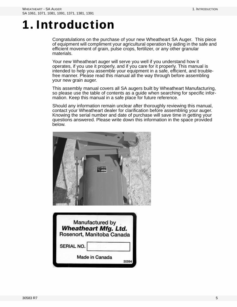
Should any information remain unclear after thoroughly reviewing this manual, contact your Wheatheart dealer for clarification before assembling your auger. Knowing the serial number and date of purchase will save time in getting your questions answered. Please write down this information in the space provided below.
30583 R7 5

1. INTRODUCTION WHEATHEART - SA AUGER
SA 1061, 1071, 1081, 1091, 1371, 1381, 1391
6 30583 R7
WHEATHEART - SA AUGER 2. SAFETY FIRST
SA 1061, 1071, 1081, 1091, 1371, 1381, 1391
2. Safety FirstThe Safety Alert symbol to the left identifies important safety messages on the product and in the manual. When you see this symbol, be alert to the possibil-ity of personal injury or death. Follow the instructions in the safety messages. Why is SAFETY important to you?
Three big reasons:
• Accidents disable and kill.• Accidents cost.• Accidents can be avoided.
SIGNAL WORDS
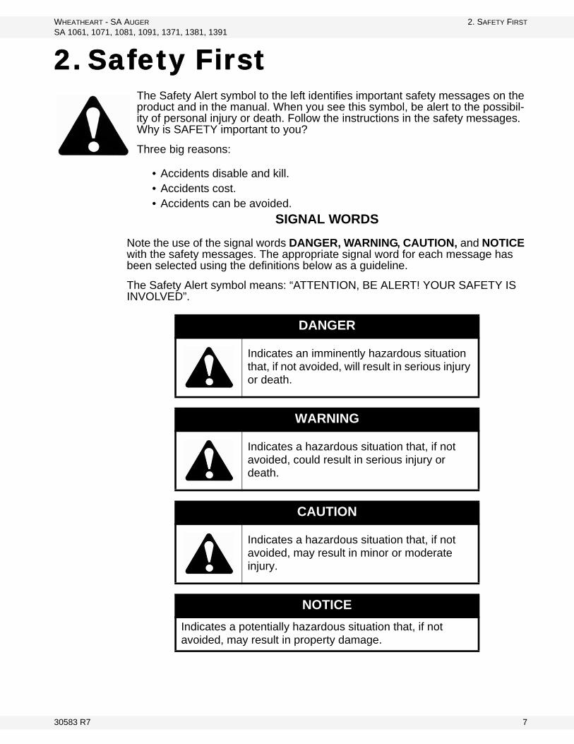
Note the use of the signal words DANGER, WARNING, CAUTION, and NOTICE with the safety messages. The appropriate signal word for each message has been selected using the definitions below as a guideline.
The Safety Alert symbol means: “ATTENTION, BE ALERT! YOUR SAFETY IS INVOLVED”.
DANGER
Indicates an imminently hazardous situation that, if not avoided, will result in serious injury or death.
WARNING
Indicates a hazardous situation that, if not avoided, could result in serious injury or death.
CAUTION
Indicates a hazardous situation that, if not avoided, may result in minor or moderate injury.
NOTICE
Indicates a potentially hazardous situation that, if not avoided, may result in property damage.
30583 R7 7

2. SAFETY FIRST WHEATHEART - SA AUGER
2.1. GENERAL SAFETY SA 1061, 1071, 1081, 1091, 1371, 1381, 1391
2.1. GENERAL SAFETY
Important: The general safety section includes instructions that apply to all safety practices. Any instructions specific to a certain safety practice (e.g., assembly safety), can be found in the appropriate section. Always read the complete instructional sections and not just these safety summaries before doing anything with the equipment.
YOU are responsible for the SAFE use and maintenance of your equipment. YOU must ensure that you and anyone else who is going to work around the equipment understands all procedures and related SAFETY information contained in this manual.
Remember, YOU are the key to safety. Good safety practices not only protect you, but also the people around you. Make these practices a working part of your safety program.
• It is the equipment owner and the operator's responsibility to read and under-stand ALL safety instructions, safety decals, and manuals and follow them before assembling, operating, or maintaining the equipment. All accidents can be avoided.
• Equipment owners must give instructions and review the information initially and anually with all personnel before allowing them to operate this product. Untrained users/operators expose themselves and bystanders to possible serious injury or death.
• Use this equipment for its intended purposes only.• Do not modify the equipment in any way. Unauthorized modification may
impair the function and/or safety, and could affect the life of the equipment. Any modification to the equipment voids the warranty.
• Do not allow children, spectators, or bystanders within the work area.• Have a first-aid kit available for use should the need arise, and know how to
use it.• Provide a fire extinguisher for use in case of an accident. Store in a highly vis-
ible place.• Wear appropriate protective gear. This list includes, but
is not limited to:• a hard hat• gloves• protective shoes with slip-resistant soles• protective goggles• hearing protection• dust mask or respirator
• For Powered Equipment: before servicing, adjusting, or repairing powered equipment, unplug, place all controls in neutral or off position, stop the engine or motor, remove ignition key or lock out power source, and wait for all mov-ing parts to stop.
8 30583 R7
WHEATHEART - SA AUGER 2. SAFETY FIRST
SA 1061, 1071, 1081, 1091, 1371, 1381, 1391 2.2. ASSEMBLY SAFETY
• Follow good shop practices:• keep service area clean and dry• be sure electrical outlets and tools are properly
grounded• use adequate light for the job at hand• Think SAFETY! Work SAFELY!
2.2. ASSEMBLY SAFETY
• Use properly sized tools, stands, jacks and hoists at all times.• Use 2 men or the proper equipment to handle the heavy bulky components.• Keep the assembly area neat and clean to prevent slipping or tripping.• Place safety stands or large blocks under the machine or components before
going beneath the component for assembly.• Stay away from overhead power lines and obstructions when lifting the
machine during assembly. Contact with power lines can cause electrocution. Contact with obstructions can damage components or cause them to fail.
• Tighten all fasteners to their specified torque before using the machine.• Make sure the truss cables have the proper tension and are not damaged like
fraying, kinking, or unwinding.• Make sure the hydraulic hoses are not kinked and the hoses and fittings don’t
leak.
2.3. SAFETY DECAL LOCATIONS
• Keep safety decals clean and legible at all times.• Replace safety decals that are missing or have become illegible. See decal
location figures that follow.• Replaced parts must display the same decal(s) as the original part.• Safety decals are available from your distributor, dealer, or factory.
2.3.1. DECAL INSTALLATION
1. Decal area must be clean and dry, with a temperature above 50°F (10°C).2. Decide on the exact position before you remove the backing paper.3. Align the decal over the specified area and carefully press the small portion
with the exposed sticky backing in place.4. Slowly peel back the remaining paper and carefully smooth the remaining
portion of the decal in place.5. Small air pockets can be pierced with a pin and smoothed out using the sign
backing paper.
30583 R7 9

2. SAFETY FIRST WHEATHEART - SA AUGER
2.3. SAFETY DECAL LOCATIONS SA 1061, 1071, 1081, 1091, 1371, 1381, 1391
2.3.2. DECAL LOCATIONS
Replicas of the safety decals that are attached to the equipment are shown in the figure(s) that follow. Proper safety procedures require that you familiarize yourself with the various safety decals and the areas or particular functions that the decals apply to as well as the safety precautions that must be taken to avoid serious, injury, death, or damage.
Figure 2.1
DECAL #17100
10 30583 R7

WHEATHEART - SA AUGER 2. SAFETY FIRST
SA 1061, 1071, 1081, 1091, 1371, 1381, 1391 2.3. SAFETY DECAL LOCATIONS
Figure 2.2
DECAL #17098
DECAL #17097
DECAL #17096
DECAL #17398
DECAL #17101
DECAL #27709
DECAL #17113
DECAL # 17378NOT INCLUDED ON SA1061
30583 R7 11

2. SAFETY FIRST WHEATHEART - SA AUGER
2.3. SAFETY DECAL LOCATIONS SA 1061, 1071, 1081, 1091, 1371, 1381, 1391
Figure 2.3
Figure 2.4 1081 / 1091 / 1371 / 1381 / 1391 Models Only
PLACED ON MACHINE BEHIND GUARD
DECAL #17099
DECAL #17107
DECAL #18859
DECAL #19960
DECAL #17531
DECAL #17098
DECAL #17101
DECAL #27709
DECAL #17094
DECAL # 27516
12 30583 R7

WHEATHEART - SA AUGER 3. ASSEMBLY
SA 1061, 1071, 1081, 1091, 1371, 1381, 1391 3.1. GENERAL ASSEMBLY
3. Assembly
Familiarize yourself with all the sub-assemblies and hardware making up the auger. Do not take chances with safety. The components are large, heavy, and can be hard to handle. Be sure to use the proper tools, stands, jacks, and hoists for the job.
Important: These instructions are written on the assumption that 2 or more people will be available for the assembly procedure. Because of the weight, it is unwise to attempt assembly of the auger alone.
Note: When tightening all fasteners, see Section 4. for proper torque specifications
3.1. GENERAL ASSEMBLY
1. Select an assembly area that is level, has a firm or hard surface and is free of debris. Be sure it is large enough to allow access from all sides when the components are being assembled.
2. If assembling inside a building, be sure the ceiling is at least 14’ (4.27 m) high to provide clearance when installing the undercarriage
3. Bring all the tools, blocks, stands, jacks, and hoists to the assembly area before starting.
4. The following tools and equipment are required to assemble the machine:
Warning: Before continuing, please read the safety information relevant to this section in the safety section of this manual. Failure to follow the safety instructions can result in serious injury, death, or property damage.
2-4 Pipe stands2 Saw horses (1200 lb / 544.3 kg)1 Standard socket set and wrench set1 Torque wrench 1 Standard 25’ (7.62 m) tape measure1 2’ level1 8” level magnetic2 C-clamps or vise grips
1Picker with minimum reach of 12’ (3.66 m) 4000-6000 lb (1814 - 2722 kg) lifting capacity
1 100’ ( 30 m) measuring tape1 Tire gauge1 Tire chuck
30583 R7 13
3. ASSEMBLY WHEATHEART - SA AUGER
3.2. AUGER TUBE ASSEMBLY SA 1061, 1071, 1081, 1091, 1371, 1381, 1391
3.2. AUGER TUBE ASSEMBLY
3.2.1. TUBE AND FLIGHTING ASSEMBLY
Note: See Table 3.1 for the number of tube sections and their lengths.Assemble the auger starting with the discharge section and working toward the intake section, following the instructions in step 2. and 3.
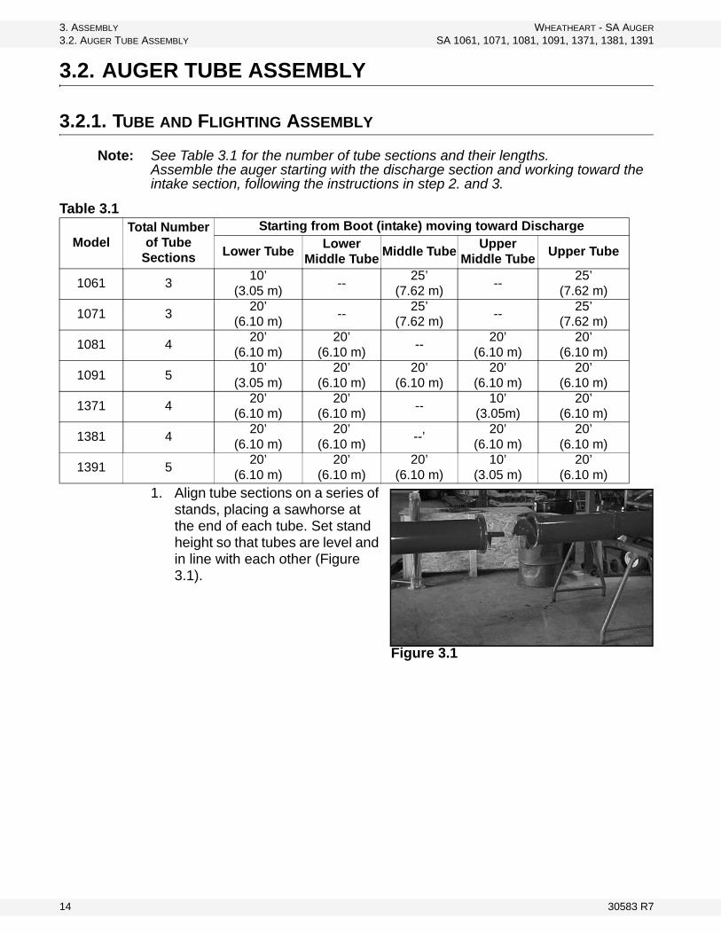
1. Align tube sections on a series of stands, placing a sawhorse at the end of each tube. Set stand height so that tubes are level and in line with each other (Figure 3.1).
Table 3.1
ModelTotal Number
of Tube Sections
Starting from Boot (intake) moving toward Discharge
Lower TubeLower
Middle TubeMiddle Tube
Upper Middle Tube
Upper Tube
1061 310’
(3.05 m)--
25’(7.62 m)
--25’
(7.62 m)
1071 320’
(6.10 m)--
25’(7.62 m)
--25’
(7.62 m)
1081 420’
(6.10 m)20’
(6.10 m)--
20’(6.10 m)
20’(6.10 m)
1091 510’
(3.05 m)20’
(6.10 m)20’
(6.10 m)20’
(6.10 m)20’
(6.10 m)
1371 420’
(6.10 m)20’
(6.10 m)--
10’(3.05m)
20’(6.10 m)
1381 420’
(6.10 m)20’
(6.10 m)--’
20’(6.10 m)
20’(6.10 m)
1391 520’
(6.10 m)20’
(6.10 m)20’
(6.10 m)10’
(3.05 m)20’
(6.10 m)
Figure 3.1
14 30583 R7

WHEATHEART - SA AUGER 3. ASSEMBLY
SA 1061, 1071, 1081, 1091, 1371, 1381, 1391 3.3. BOOT ASSEMBLY
2. Slide lower flighting shaft into upper flight. Rotate the flights so that the flightings overlap and bolt holes line up. DO NOT over tighten bolts. Secure with two GR8 bolts (1) and locknuts (2) (Figure 3.2).
3. Slide tube sections together and insert the eight 7/16” x 1” GR8 bolts (3) (SA10) or twelve 7/16” x 1-1/4” GR8 bolts (SA13) and 7/16” locknuts (4). Ensure the tube sections are aligned so the brackets are in the proper position (Figure 3.2).
3.3. BOOT ASSEMBLY.\
Note: The gearbox is sent from the factory filled half way with EP90 gear oil. Before further assembly, check oil level to make certain the gearbox is half full. Add oil if necessary. Do not use grease.
1. SA10 only: Slide the short flighting section (1) onto the lower flighting shaft (2) and secure it with a 7/16” x 3 1/2” bolt (3) and 7/16 locknut (4). Make sure that flight ends butt together for continuous flow (Figure 3.3).
2. At the upper end of the auger tube, loosen the set screw and the locking collar on the upper bearing.
3. SA13 only: Loosen the large nut on the flight so that it is half on the thread and half off, leaving the collar and shim on the flight.
4. Slip the boot assembly over the lower flighting shaft (2) and attach it to the flange on the lower tube with eight 7/16” x 1” GR8 bolts (SA10) or twelve 7/16” x 1-1/4” GR8 bolts (SA13) and 7/16” locknuts. Tighten them securely.
5. Slide the wide rim 1-1/4” flat washer (SA10) or 1-3/4” (SA13) (6) onto the lower flighting shaft (2).
Important: Using 5/8” x 1-3/4” bolts and nylon lock nuts install the washer between the boot assembly and the bearing to protect the bearing from foreign debris. Do Not tighten bolts yet.
Figure 3.2
WARNING
Components are heavy and create a crushing hazard if improperly handled. Be sure to use proper hoisting equipment and procedures, and ensure lifting apparatus is secure. Lock out the lifting apparatus before working around or under the raised components; failure to do so may cause serious personal injury.
30583 R7 15

3. ASSEMBLY WHEATHEART - SA AUGER
3.3. BOOT ASSEMBLY SA 1061, 1071, 1081, 1091, 1371, 1381, 1391
6. Clean paint from inside lower bearing and install, seating the flighting shaft shoulder against the washer.
7. Secure the locking collar (7) and tighten the set screw (8) on the lower bearing.
8. Install the 1/4” x 3” (SA10), or the 3/8” x 3-1/2” (SA13) square key (9) and slide the sprocket (10) onto flighting shaft. Align lower sprocket with upper sprocket using a straight edge, and tighten set screws.
Note: It is recommended you use a thread locking compound that meets or exceeds Loctite Blue© on all set screws.
9. Install chain (2) on sprockets. With the chain in place and tensioned to about 1/4” deflection, tighten the 4 bolts on the bearing. Oil the chain lightly (Figure 3.4).
10. SA 1061, 1071, 1081: Secure the flighting on the upper bearing with the set screw and locking collar.
For ease of PTO installation, sprocket shield should be attached after the instal-lation of the PTO driveline. See “PTO Driveline” on page 48.
Figure 3.3
16 30583 R7

WHEATHEART - SA AUGER 3. ASSEMBLY
SA 1061, 1071, 1081, 1091, 1371, 1381, 1391 3.4. THRUST ADJUSTER AND DISCHARGE SPOUT INSTALLATION
Important: To prevent premature failure of the lower bearing, ensure it has been assembled in the correct sequence.
3.4. THRUST ADJUSTER AND DISCHARGE SPOUT INSTALLATION
DISCHARGE SPOUT
1. Align the discharge spout (11) over the opening in the tube.2. Attach the discharge spout (11) with two 7/16” x 1-3/4” bolts (3) and 7/16”
locknuts (4) (Figure 3.5).Note: The thrust adjuster is designed to transfer some pressure from the lower flight
bearing to the upper flight bearing (Figure 3.5).
SA13 THRUST ADJUSTER
1. Turn the nut (7) until it is snug against the bushing (6). Once it is snug, turn nut another 3 or 4 full turns.
3. Secure the lock collar (5) and tighten the set screw.
4. Install cover (8) over the two longer 5/8” bolts (9) and secure with two 5/8” Nylock nuts (10).
SA1091 THRUST ADJUSTER
1. Remove the upper bearing lock collar (if necessary).
2. Screw out the 4 bolts on the adjuster plate so plate rests against head plate and foam gasket is fully compressed.
3. Secure lock collar on upper bearing and tighten set screw.4. Adjust the 4 bolts on the adjuster plate alternately, keeping it parallel to the
head plate until all slack is taken up. Tighten until plate moves about 1/4” (0.64 cm) more.
Figure 3.4
Figure 3.5
30583 R7 17
3. ASSEMBLY WHEATHEART - SA AUGER
3.5. AUGER END TUBE DISASSEMBLY / REASSEMBLY SA 1061, 1071, 1081, 1091, 1371, 1381, 1391
5. Lock the nuts against the welded nuts on the adjuster plate.
3.5. AUGER END TUBE DISASSEMBLY / REASSEMBLY
The end tube may be removed in order to reduce transport length and height.
1. With auger intake secured, give the cable some slack by lifting the discharge end of the auger so that the tube has a slight upward deflection. Remove trussing cable supporting the end tube.
2. Disconnect the drive mechanism by removing the PTO driveline chain (2) (Figure 3.4) and sprocket (10) (Figure 3.3). Loosen the locking collar (7) (Figure 3.3) on the lower bearing, allowing the lower flighting shaft to slide.
3. Remove 7/16” bolts (3) (Figure 3.3) at the flange connector closest to the discharge end. Slide the tube with flighting attached back far enough to remove the two GR8 bolts (1) (Figure 3.3) that hold the flighting sections together.
4. Remove end tube with flighting.5. To reassemble the end tube, lift the intake end of the auger up with the swing
hopper into transport position until the auger tube is sitting fairly level. Support auger at both ends before lifting the end tube up into place.
6. Slide flighting shafts together with flight ends butting together for continuous flow. Secure with two GR8 bolts (1) and locknuts (2) (Figure 3.3).
7. Align end tube with the discharge spout facing down. Slide tube sections together and insert the eight 7/16” x 1” GR8 bolts (3) (SA10) or twelve 7/16” x 1-1/4” GR8 bolts (SA13), and 7/16” locknuts (4).
8. Reattach drive mechanism. See steps 5-7 and 9-10 in Section 3.3. 9. Reattach truss cables. To give the cable some slack, lift the discharge end of
the auger so that the tube has a slight upward deflection. Tighten the nut on the eye bolt to increase the tension in the cable.
Note: See operation manual maintenance section for truss cable service.
The cables are properly adjusted when:
• The tube is straight side-to-side.• The discharge end is deflected sightly upwards.• There is no slack in the cables.
18 30583 R7
WHEATHEART - SA AUGER 3. ASSEMBLY
SA 1061, 1071, 1081, 1091, 1371, 1381, 1391 3.6. TRUSS AND CABLE ASSEMBLY
3.6. TRUSS AND CABLE ASSEMBLY
3.6.1. BRACKET AND BRIDGE INSTALLATION
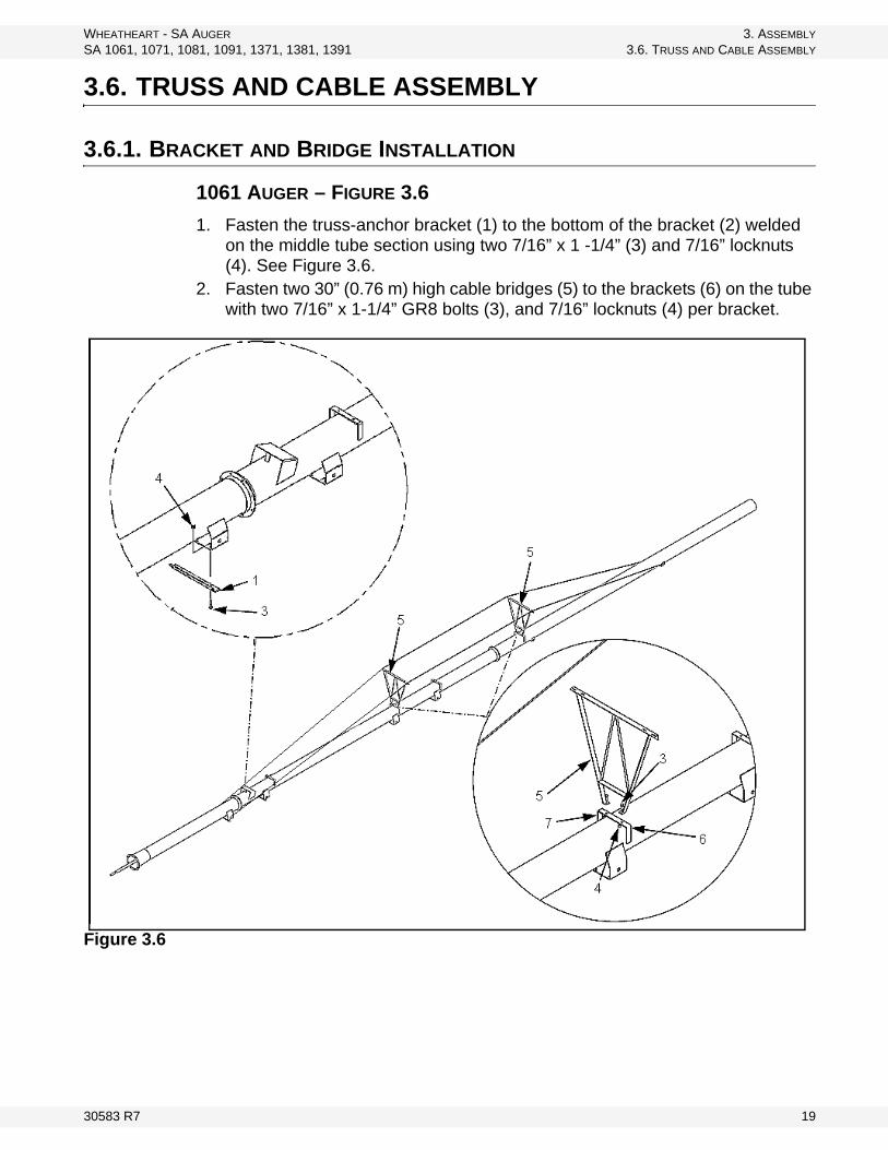
1061 AUGER – FIGURE 3.6
1. Fasten the truss-anchor bracket (1) to the bottom of the bracket (2) welded on the middle tube section using two 7/16” x 1 -1/4” (3) and 7/16” locknuts (4). See Figure 3.6.
2. Fasten two 30” (0.76 m) high cable bridges (5) to the brackets (6) on the tube with two 7/16” x 1-1/4” GR8 bolts (3), and 7/16” locknuts (4) per bracket.
Figure 3.6
30583 R7 19

3. ASSEMBLY WHEATHEART - SA AUGER
3.6. TRUSS AND CABLE ASSEMBLY SA 1061, 1071, 1081, 1091, 1371, 1381, 1391
1071 AUGER – FIGURE 3.7
1. Fasten the 2 truss-anchor brackets (1) to the bottom of the brackets (2) that are welded on the lower tube section and the middle tube section. Use two 7/16” x 1-1/4” GR8 bolts (3) and 7/16” locknuts (4) per bracket.
2. Fasten three 30” high cable bridges (5) to the brackets (6) on the tube sections with two 7/16” x 1-1/4” (3) and 7/16” locknuts (4) per cable bridge.
Figure 3.7
20 30583 R7
WHEATHEART - SA AUGER 3. ASSEMBLY
SA 1061, 1071, 1081, 1091, 1371, 1381, 1391 3.6. TRUSS AND CABLE ASSEMBLY
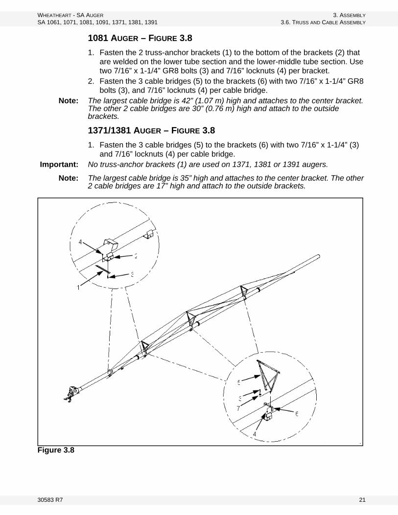
1081 AUGER – FIGURE 3.8
1. Fasten the 2 truss-anchor brackets (1) to the bottom of the brackets (2) that are welded on the lower tube section and the lower-middle tube section. Use two 7/16” x 1-1/4” GR8 bolts (3) and 7/16” locknuts (4) per bracket.
2. Fasten the 3 cable bridges (5) to the brackets (6) with two 7/16” x 1-1/4” GR8 bolts (3), and 7/16” locknuts (4) per cable bridge.
Note: The largest cable bridge is 42” (1.07 m) high and attaches to the center bracket. The other 2 cable bridges are 30” (0.76 m) high and attach to the outside brackets.
1371/1381 AUGER – FIGURE 3.8
1. Fasten the 3 cable bridges (5) to the brackets (6) with two 7/16” x 1-1/4” (3) and 7/16” locknuts (4) per cable bridge.
Important: No truss-anchor brackets (1) are used on 1371, 1381 or 1391 augers.
Note: The largest cable bridge is 35” high and attaches to the center bracket. The other 2 cable bridges are 17” high and attach to the outside brackets.
Figure 3.8
30583 R7 21

3. ASSEMBLY WHEATHEART - SA AUGER
3.6. TRUSS AND CABLE ASSEMBLY SA 1061, 1071, 1081, 1091, 1371, 1381, 1391
1091 AUGER – FIGURE 3.9 (PAGE 24)
1. There are support tubes at each end and at truss E. Note: Due to rigidity of the tubular trussing, do not put an upward bow in the auger.
Assemble trussing with main auger tube straight/level and well supported over its length. When assembling the truss system, DO NOT tighten any bolts until all components are in place.
Mount 2 trusses on opposite sides, in each location.
2. Loosely attach the 4 low (in locations A and G) and 10 high (locations B through F) truss towers to the truss-attach brackets (1) that are welded to the auger tubes, with 7/16” x 1-1/4” GR8 bolts (2) and 7/16” locknuts (3) (View A).
3. Assemble the adjustable top brace tube (4) that attaches between truss tower E and F with 2 tubes of equal length—one with a left-hand threaded rod and one with a right-hand threaded rod.
• Then thread a 3/4” right-hand threaded nut (7) onto the rod. • Join the tubes with a turn buckle (8), threading equally onto each rod. • The hole-to-hole distance after assembly is 92-1/2” (2.35 m) (View B).
3. Repeat step 3 for adjustable top brace tubes 5 and 6. • Tube 5 is 147-1/2” (3.75 m) hole-to-hole, and is located between truss
towers D and E. • Tube 6 is 119” (3.02 m) hole-to-hole, and is located between truss towers
C and D. 4. With 2 of the long adjust-tubes (10 and 11):
• thread a 3/4” nut (9) • insert the threaded end of one of the adjust-tubes into the truss anchor
bracket (12) on the intake auger tube• insert the other adjust-tube into the anchor bracket (13) on the discharge
tube (View C)5. At truss towers A and G join the adjust-tubes (10 and 11), and a 10’ (3.05 m)
truss tube (14) to the truss tower with a 1/2” x 2-1/2” GR5 bolt (15), and 1/2” locknut (16) (View D).
6. Thread a second 3/4” nut (17) onto the 2 adjust-tubes (10 and 11) (View C).7. At truss tower B join:
• the 10’ truss tube (14) attached to truss tower A • 2 crossbrace tubes (18)• another 10’ (3.05 m) truss tube (14) with a 1/2” x 2-1/2” bolt (15) and 1/2”
locknut (16) (View D). Do not tighten.8. At truss tower C join:
• the 10’ (3.05 m) truss tube (14) attached to truss tower B, • an adjustable top brace tube (6), and• 2 crossbrace tubes (18) with a 1/2” x 2-1/2” bolt (15) and 1/2” locknut (16)
(View D). Do not tighten.9. On the remaining long adjust-tube (19), thread a 3/4” nut, and insert the
threaded end into the truss anchor bracket (20) on the auger tube.10. At truss tower D join:
22 30583 R7

WHEATHEART - SA AUGER 3. ASSEMBLY
SA 1061, 1071, 1081, 1091, 1371, 1381, 1391 3.6. TRUSS AND CABLE ASSEMBLY
• the adjustable top brace tubes (5 and 6), • the adjust-tube (19) attached at point (20), • and a crossbrace tube (18) with a 1/2” x 2-1/2” bolt (15) and 1/2” locknut
(16). Do not tighten (View D).11. Thread a second 3/4” nut (17) onto the adjust-tube (19) (View C).12. Thread a 3/4” nut onto the short adjust-tube (21), then insert the threaded
end into the truss anchor point (22) on the auger tube.13. At truss tower F join:
• the 10’ (3.05 m) truss-tube (14) attached to truss tower G • the adjust-tube (21) attached at point (22)• a crossbrace tube (18)• and an adjustable top brace tube (4) with a 1/2” x 2-1/2” bolt (15) and
1/2” locknut (16). (View D) Do not tighten.14. Thread a second 3/4” nut (17) onto the adjust-tube (21) (View C).15. Using 1/2” x 1-1/2” bolts (23) and 1/2” locknuts (24), loosely connect all the
crossbrace tubes (17) to tabs welded to the top of the truss attach brackets (1) (View E).
Note: Attach these tubes to the same side of the tab as they are connected to the truss tower.
16. Tighten all bolts and nuts except the 3/4” nuts (9 and 17) on the adjustment tubes (10, 11, 19 and 21) (View C).
17. At each point where the crossbrace tubes meet (between towers B - C and C - D) install one pair of x-clamps (25) with two 7/16” x 1” bolts (26) and 7/16” locknuts (27) each (View F).
18. Adjust the threaded adjustment tubes (11 and 19) until the auger tubes have a slight upward bow (1” to 1-1/2” over the length of the auger). Lock the adjustment nuts (9 and 17) against the brackets (View C).
19. Adjust the threaded adjust tubes (10 and 21) until the lower 2 auger tubes have a slight downward bow (less than 1/4” over the lower 2 tubes). Lock the adjustment nuts (9 and 17) against the brackets (View C).
20. Adjust the turn buckles in 4 and 5 so that the bolt holes are in line with the bolt hole in truss tower E, and there is no tension in adjustment tubes 4 and 5. Install a 1/2” x 2-1/2” bolt (15) and a 1/2” locknut (16) (View D).
30583 R7 23

3. ASSEMBLY WHEATHEART - SA AUGER
3.6. TRUSS AND CABLE ASSEMBLY SA 1061, 1071, 1081, 1091, 1371, 1381, 1391
Figure 3.9
24 30583 R7

WHEATHEART - SA AUGER 3. ASSEMBLY
SA 1061, 1071, 1081, 1091, 1371, 1381, 1391 3.6. TRUSS AND CABLE ASSEMBLY
1391 AUGER – FIGURE 3.10
When assembling the truss system, do not tighten any bolts until all compo-nents are in place. Refer to Figure 3.10 and for correct positioning of the truss components.
1. Loosely attach the 2 low (D) and 4 high (C) pairs of truss towers to the truss-attach brackets welded to auger tube with four 7/16” x 1-1/4” bolts and locknuts pair of truss towers.
2. Loosely join the ends of two 10' (3.05 m) truss-tubes (A) and two crossbrace tubes (B) between the top end of each pair of high truss towers using 1/2” x 2-3/4” bolts and locknuts.
3. Thread a 3/4” nut onto each adjust-tube, then insert threaded end into truss-anchors on lower and upper auger tubes. Join the adjust tubes and 10' truss tubes at the two low (D) truss towers with 1/2” x 2-3/4” bolts and locknuts.
Note: A single crossbrace is positioned between the low (D) truss towers and adjacent high (C) truss towers.
4. Loosely join all the crossbrace tubes to tabs welded to top of truss-attach brackets using 1/2” x 1-1/2” bolts and locknuts.
Note: Attach these tubes to same side of tab as they are attached to the truss tower.
Note: The hole in the crossbrace tubes should be near centered in the slots on the welded tabs on the tube. If most crossbraces are to one end of the slot or the other, they can be shifted by adjusting the adjust tubes at the ends of the truss to move the truss more towards the bottom or top.
5. Tighten all bolts and nuts.6. Install the 3 pairs of x-clamps where the crossbrace tubes meet (between the
4 high (C) truss towers) with two 7/16” x 1" bolts and locknuts each.7. Adjust the threaded adjust tubes (E) (Figure 3.10) until upper and lower auger
tubes have a slight upward bow. Lock the adjust nuts against bracket.
30583 R7 25

3. ASSEMBLY WHEATHEART - SA AUGER
3.6. TRUSS AND CABLE ASSEMBLY SA 1061, 1071, 1081, 1091, 1371, 1381, 1391
Figure 3.10
CABLE TRUSSING
See Figure 3.11 and 3.12.
4. Attach an eyebolt to one end of each truss cable with two 3/8” cable clamps using about 10" (25.4 cm) - 12" (30.5 cm) of cable. Tighten securely.
Figure 3.11
5. Insert eyebolts into adjust bracket (F) and thread on nut about 1/2”.
26 30583 R7

WHEATHEART - SA AUGER 3. ASSEMBLY
SA 1061, 1071, 1081, 1091, 1371, 1381, 1391 3.6. TRUSS AND CABLE ASSEMBLY
6. Starting between the third and fourth truss-cable supports on one side, and fourth and fifth supports on the other side, loosely attach the truss cables to each truss-cable support with a 5/16” cable clamp as shown in Figure 3.10.
7. Pull cable around truss cable anchors at top and bottom end of auger tube and loosely attach with a 5/16” cable clamp as shown in Figure 3.12.
8. Attach remaining eyebolts to adjust bracket and thread on nuts about 1/2”.
9. Thread loose ends of the cable through eyebolt, pull tight, then secure with two 3/8” cable clamps. Tighten securely.
10. Adjust tension of both truss cables by tightening the eyebolts at the adjust brackets. These cables must be very tight. Also adjust for side alignment.
11. Now tighten all of the cable clamps at cable supports and arms.
Figure 3.12
30583 R7 27

3. ASSEMBLY WHEATHEART - SA AUGER
3.6. TRUSS AND CABLE ASSEMBLY SA 1061, 1071, 1081, 1091, 1371, 1381, 1391
Figure 3.13
28 30583 R7

WHEATHEART - SA AUGER 3. ASSEMBLY
SA 1061, 1071, 1081, 1091, 1371, 1381, 1391 3.6. TRUSS AND CABLE ASSEMBLY
3.6.2. CABLE INSTALLATION AND TIGHTENING
1061 AUGER – FIGURE 3.14
Figure 3.14
Note: The 1061 auger uses one 90’ (27.43 m) cable.
1. Continue to support the tube with at least 3 stands (one at each end and one in the middle). Shim the stands at the end to insert desired curve, approxi-mately 5”.
2. Attach eyebolt (1) to one end of a 90’ truss cable (2) with two 1/4” cable clamps (3) doubling-back about 12” of cable. Insert the eyebolt (1) into the truss anchor bracket (4) and thread on a 1/2” locknut (5) a short way.
3. Pull the truss cable:• over the cable bridge (6)• around the cable return bracket (7)• back over the cable bridge (6)• back to the cable anchor bracket (4)
Note: The truss cable (2) is to be installed on the outer slot on the cable bridges.
4. Use loosely attached cable clamps to hold the cable in place — 2 cable clamps on the cable bridges and 2 clamps on the cable return bracket.
Note: Do not tighten the cable clamps at this time.
5. Place the other eyebolt in the cable anchor bracket and thread on a 1/2” locknut a short way.
30583 R7 29

3. ASSEMBLY WHEATHEART - SA AUGER
3.6. TRUSS AND CABLE ASSEMBLY SA 1061, 1071, 1081, 1091, 1371, 1381, 1391
6. Thread the end of the truss cable through the eyebolt and pull the cable snug. Double-back the cable and secure in place with 2 cable clamps as in step 2.
Note: If there isn’t enough cable loosen the clamps on the opposite eyebolt and adjust the cable. Retighten clamps.
7. Tighten the eyebolts evenly to take the remaining slack out of the truss cable. Once the long cable (2) is tightened, repeat for the short cables.
8. Check for proper side-to-side alignment, and then tighten the cable clamps on the cable bridge (6) and the cable return bracket (7).
1071 AND 1081 AUGERS – FIGURE 3.15
Figure 3.15
1. Continue to support the tube with at least 3 stands (one at each end and one in the middle). Shim the stands at the end to insert desired curve, approxi-mately 7” (17.8 cm) for the 1071 and 9” (22.9 cm) for the 1081.
Note: The 1071 and 1081 augers use 2 cables: the 1071 cables are 57-1/2’ (17.5 m) and 106’ (32.3 m) long, the 1081 cables are 73’ (22.25 m) and 128’ (39.0 m)long.
2. Attach an eyebolt (1) to one end of each truss cable (2 and 3) with 2 cable clamps (4) doubling-back about 12” (30.5 cm) of cable. Insert the eyebolts into the appropriate truss anchor bracket (5) and thread on a 1/2” locknut (6) a short way.
3. Pull the long truss cable:• over the cable bridges (7)
30 30583 R7

WHEATHEART - SA AUGER 3. ASSEMBLY
SA 1061, 1071, 1081, 1091, 1371, 1381, 1391 3.6. TRUSS AND CABLE ASSEMBLY
• around the cable return bracket (8)• back over the cable bridges• and back to the cable anchor bracket (5)
4. Pull the short truss cable (3):• over the middle cable bridge (7)• around the cable return bracket (8)• back over the middle cable bridge• and back to the cable anchor bracket (5)
Important: The long truss cable (2) must be installed on the outside of the middle bridge (7).
5. Use loosely attached cable clamps to hold the cable in place — 2 cable clamps per cable bridge and 2 clamps on the cable return bracket.
Note: Do not tighten the cable clamps at this time.
6. Place another eyebolt in each cable anchor bracket and thread on a 1/2” locknut a short way.
7. Thread the end of each truss cable through the appropriate eyebolt and pull the cable snug. Double-back the cable and secure in place with 2 cable clamps as in step 2.
Note: If there isn’t enough cable, loosen the clamps on the opposite eyebolt and adjust the cable. Retighten clamps.
8. Tighten the eyebolts on the long cable (2) evenly to take the remaining slack out of the truss cable. Once the long cable (2) is tightened, repeat for the short cable (3).
9. Check for proper side-to-side alignment and then tighten the cable clamps on the cable bridges and the cable return brackets.
30583 R7 31
3. ASSEMBLY WHEATHEART - SA AUGER
3.6. TRUSS AND CABLE ASSEMBLY SA 1061, 1071, 1081, 1091, 1371, 1381, 1391
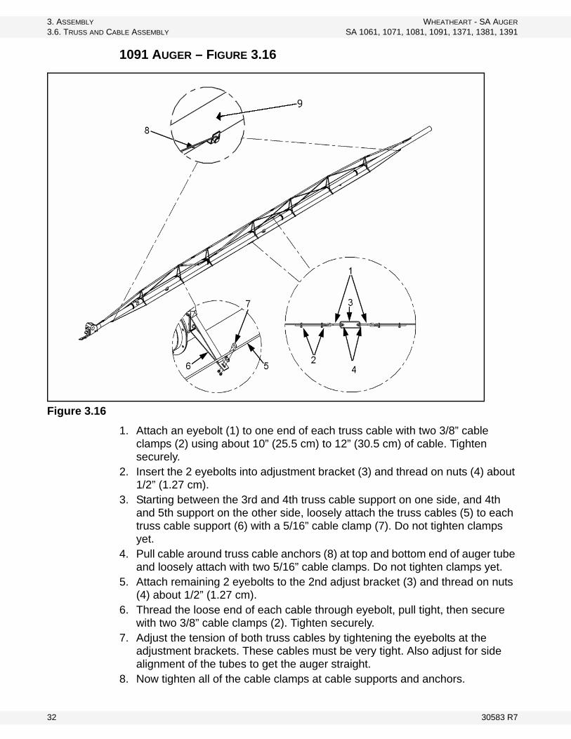
1091 AUGER – FIGURE 3.16
Figure 3.16
1. Attach an eyebolt (1) to one end of each truss cable with two 3/8” cable clamps (2) using about 10” (25.5 cm) to 12” (30.5 cm) of cable. Tighten securely.
2. Insert the 2 eyebolts into adjustment bracket (3) and thread on nuts (4) about 1/2” (1.27 cm).
3. Starting between the 3rd and 4th truss cable support on one side, and 4th and 5th support on the other side, loosely attach the truss cables (5) to each truss cable support (6) with a 5/16” cable clamp (7). Do not tighten clamps yet.
4. Pull cable around truss cable anchors (8) at top and bottom end of auger tube and loosely attach with two 5/16” cable clamps. Do not tighten clamps yet.
5. Attach remaining 2 eyebolts to the 2nd adjust bracket (3) and thread on nuts (4) about 1/2” (1.27 cm).
6. Thread the loose end of each cable through eyebolt, pull tight, then secure with two 3/8” cable clamps (2). Tighten securely.
7. Adjust the tension of both truss cables by tightening the eyebolts at the adjustment brackets. These cables must be very tight. Also adjust for side alignment of the tubes to get the auger straight.
8. Now tighten all of the cable clamps at cable supports and anchors.
32 30583 R7

WHEATHEART - SA AUGER 3. ASSEMBLY
SA 1061, 1071, 1081, 1091, 1371, 1381, 1391 3.7. FRAME ASSEMBLY
1371 AND 1381 AUGER
Follow similar procedure as outlined for 1071/1081 with exception of eyebolt installation. Eyebolts are attached to weld on tabs.
The 1371, 1381, and 1391 augers use 2 cables:
• the 1371 cables are 58’ (17.7 m) and 91’ (27.7 m) long• the 1381 cables are 75’ (22.9 m) and 115’ (35.1 m) long
3.7. FRAME ASSEMBLY
3.7.1. SCISSOR FRAME ASSEMBLY
ALL AUGERS – FIGURE 3.17
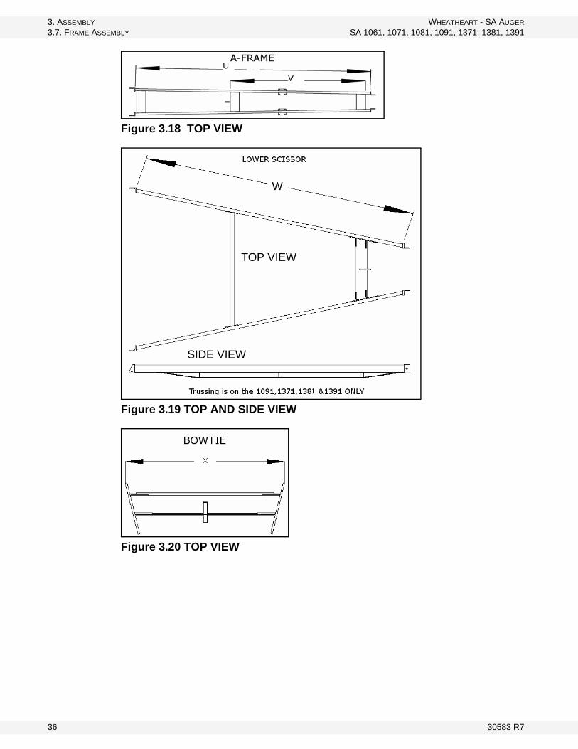
Note: Refer to Table 3.2 and Figure 3.17 to 3.22 for the length of each auger component.
1. Mount wheels (1) to hubs (2) on axle (3) with 6 wheel bolts (4). Note: Before installing the wheels check to make sure the hub and wheel mounting
surfaces are free from rust and debris.
2. Finger tighten the wheel bolts and verify that the wheel is sitting flush on the hub. Torque the wheel bolts to 80 ft-lb (±10 ft-lb) of torque while using the appropriate criss-cross pattern, refer to Appendix for specifications. If in doubt have a qualified tire repair service perform the required maintenance.
3. For 1081, 1091, 1371, 1381 and 1391 augers: Insert axle extensions (5) into axle (3) and pin it in place using a 3/8” x 5-1/2” pin (6) and hitch pin (7).
4. Attach the lower arms (8) to the axle (3) • using two 3/4” x 3” x 4-1/2” u-bolts (9) and four 3/4” locknuts (10) per arm • 3/4” x 3-1/2” x 5 u-bolts for the 1081,1091, 1371, 1381 and 1391
5. Space the lower arms evenly on the axle. See Figure 3.17.• 101-1/4” (2.57 m) (Z) for the 1061 and 1071 augers • 100-1/2” (2.55 m) (Z) for the 1081 and 1091 augers.• space 102” (2.59 m) for SA13 augers.
6. Tighten the u-bolts evenly by alternating between the top and bottom locknuts.
WARNING
Components are heavy and create a crushing and pinching hazard if improperly handled. Be sure to use proper hoisting equipment and procedures, and ensure lifting apparatus is secure. Lockout the lifting apparatus before working around or under the raised components. Failure to do so may cause serious personal injury.
30583 R7 33

3. ASSEMBLY WHEATHEART - SA AUGER
3.7. FRAME ASSEMBLY SA 1061, 1071, 1081, 1091, 1371, 1381, 1391
7. Place a board across the lower arms to support the lower scissor arms.8. Bolt the lower scissor arms (14 and 15) to the axle (3) with 1” x 3” bolts (16)
and 1” locknuts (17). Note: Ensure the arms are located on the correct side. The hole in the axle tab should
be at the bottom.
9. Attach the bowtie (18) to the lower scissor arms (14 and 15) using:• four 3/4” x 6” x 3-1/2” u-bolts (19) and 3/4” locknuts (20) on the 1061 and
1071 augers• four 3/4” x 6” x 4-1/2” u-bolts (19) and 3/4” locknuts (20) on the 1081 and
1091 augers• use 1” x 6” x 5” u-bolts (19) and 1” locknuts (20) on 1371, 1381, 1391.
10. Position the transport rest between the tab stops on the lower scissor arms. Don’t Tighten.
11. Attach the transport rest (21) to the lower scissor arms (14 and 15) using:• four 3/4” x 6” x 3-1/2” u-bolts (22) and 3/4” locknuts (23) on the 1061 and
1071 augers• four 3/4” x 6” x 4 -1/2” u-bolts (22) and 3/4” locknuts (23) on the 1081 and
1091 augers• use 1” x 6” x 5” u-bolts (22) and 1” locknuts (23) on the 1371, 1381, 1391
12. Position the transport rest against the tab stops so the tabs are on the axle side of the transport rest. DON’T Tighten.
13. Pin the A-Frame (24) to the lower scissor arms (14 and 15) using two 1-1/4” x 3-1/4” bolts (25) and two 1-1/4” locknuts (27).
• Use two 1-1/4” SAE washers (28) as spacers between the A-Frame and lower scissor tabs.
14. (On 1371, 1381 and 1391 use 1-1/2” x 4-1/2” bolts (25) and two 1-1/2” locknuts (27).
• Use two 1-1/2” SAE washers (28) as spacers between the A-Frame and lower scissor tabs.
15. Tighten the locknuts (20) on the u-bolts (19) for the bowtie (18):• Starting with the locknuts closest to the axle.• While tightening, ensure that the bowtie (18) is butted up against the tab
stops on the lower scissor arms (14 and 15) using the same procedure as in step 2.
• Tighten the remaining u-bolts and repeat the procedure for the transport rest (21).
34 30583 R7

WHEATHEART - SA AUGER 3. ASSEMBLY
SA 1061, 1071, 1081, 1091, 1371, 1381, 1391 3.7. FRAME ASSEMBLY
Figure 3.17
30583 R7 35
3. ASSEMBLY WHEATHEART - SA AUGER
3.7. FRAME ASSEMBLY SA 1061, 1071, 1081, 1091, 1371, 1381, 1391
Figure 3.18 TOP VIEW
Figure 3.19 TOP AND SIDE VIEW
Figure 3.20 TOP VIEW
U
V
W
TOP VIEW
SIDE VIEW
36 30583 R7

WHEATHEART - SA AUGER 3. ASSEMBLY
SA 1061, 1071, 1081, 1091, 1371, 1381, 1391 3.7. FRAME ASSEMBLY
Figure 3.22 Top View
3.7.2. ATTACHING TO TUBE
ALL AUGERS
1. Remove the stand from the intake end of the auger and raise the discharge end with a block and tackle or a front end loader and a strong sling or chain at point “A” (Figure 3.24). Height should be sufficient so the frame can be positioned under the tube.
Table 3.2
Model U V W x Y Z
1061128”
(3.25 m)63”
(1.60 m)128”
(3.25 m)46-1/2”
(1.18 m)191”
(4.85 m)101-1/4”(2.57 m)
1071155”
(3.94 m)89”
(2.26 m)145”
(3.68 m)44”
(1.12 m)228”
(5.79 m)101-1/4”(2.57 m)
1081155”
(3.94 m)71”
(1.80 m)175”
(4.44 m)45”
(1.14 m)284”
(7.21 m)100-1/2”(2.55 m)
1091196”
(4.98 m)112”
(2.84 m)175” (w/ Trussing)
(4.44 m)45”
(1.14 m)284”
(7.21 m)100-1/2”(2.55 m)
1371167”
(4.24 m)-
149” (w/ Trussing)(3.78 m)
60-1/8”(1.53 m)
229”(5.82 m)
102”(2.59 m)
1381178”
(4.52 m)-
167-3/4” (w/ Trussing)(4.26 m)
59-13/16”(1.52 m)
288”(7.32 m)
102”(2.59 m)
1391220”
(5.59 m)-
189-1/2”(w/ Trussing)(4.81 m)
58-7/16”(1.48 m)
353”(8.97 m)
102”(2.59 m)
Figure 3.21
30583 R7 37

3. ASSEMBLY WHEATHEART - SA AUGER
3.7. FRAME ASSEMBLY SA 1061, 1071, 1081, 1091, 1371, 1381, 1391
2. Position the frame under the tube assembly.
3. Lower the tube to align the frame with the bracket closest to the center cable bridge on the tube (29).
• Secure in place using 1” x 2-1/2” bolts (30) and 1” locknuts (31).
• Use two 1” SAE washers (32) as spacers between the tabs and the bracket (1 for each side) (Figure 3.25).
4. Raise the tube at point “A” so the discharge end is approximately 10’ off the ground (Figure 3.24).
• Attach a lifting device at point “B” on the lower scissor-lift frame and lift until the axle arms (8) are aligned with the lower bracket on the tube (33).
• Second bracket from the intake end on the 1061', 1071', and 1081'.
• First bracket from the intake end on the 1091’, 1371’, 1381’, and 1391’.
5. SA 10 Augers: Secure the axle arms to the attach bracket using 1” x 2-1/2” bolts, locknuts and washers. Washers should be inserted as a spacer between the axle arm and the attach bracket (Figure 3.25).
6. SA 13 Augers: Secure the axle arms to the attach bracket using 1” x 2-1/2” bolts, locknuts and washers. Stabilizer brackets must be inserted between the axle arm and the washer (Figure 3.23, 3.25). This bolt must pivot so it should not be tightened fully.
Note: It may aid alignment to use a stand to hold up the axle arms.
7. SA 13 Augers:
a. Install the short crossmember by placing it between the lower arms. Attach using two 3/4” x 3-1/2” x 5” u-bolts at each end of the short crossmember, leave finger tight until step f. See Figure 3.23.
b. Attach the stabilizer braces to the short crossmember using a 5/8” x 2” bolt
WARNING
Components are heavy and create a crushing and pinching hazard if improperly handled. Be sure to use proper hoisting equipment and procedures, and ensure lifting apparatus is secure before working around or under the raised components. Failure to do so may cause serious personal injury.
WARNING
Do not remove tube support until instructed to do so in step 8.
38 30583 R7

WHEATHEART - SA AUGER 3. ASSEMBLY
SA 1061, 1071, 1081, 1091, 1371, 1381, 1391 3.7. FRAME ASSEMBLY
and locknut. Leave the bolts loose for now.
Note: The bend angle of the stabilizer brace is different at each end. Attach the end with a smaller bend to the short crossmember.
c. Secure the two stabilizer brackets and stabilizer braces using a 5/8” x 2-1/4” bolt and locknut. The stabilizer braces should sandwich the brackets. You may have to move the short crossmember around to get the bolt in.
d. Bolt the remaining hole in the two stabilizer brackets together with a 5/8” x 1-3/4” bolt and locknut.
e. Push the short crossmember toward the stabilizer brackets until it fits gently between the two frames. Do not wedge the short crossmember in between the lower arms too tight.
f. Tighten all the bolts in the stabilizer and crossmember making sure nothing moves. Ensure the 1” x 2-1/2” lower arm bolt is left only snug, as it remains a pivot.
Figure 3.23
8. Remove the lifting device at point “B” and raise the auger at point “A” so the transport H-brace (34) can be attached. Use eight 1/2” x 1-1/2” bolts (35) and 1/2” locknuts (36) (Figure 3.25).
30583 R7 39

3. ASSEMBLY WHEATHEART - SA AUGER
3.7. FRAME ASSEMBLY SA 1061, 1071, 1081, 1091, 1371, 1381, 1391
9. Lower the auger until the transport H-brace (34) is resting on the transport rest (21) and remove the lifting device at point “A” (Figure 3.24).
10. Fasten the x-brace tubes (11) to the lower axle arms (8) and secure with 1/2” x 1-1/2” bolts (12) and locknuts (13) (Figure 3.25).
Figure 3.24
40 30583 R7

WHEATHEART - SA AUGER 3. ASSEMBLY
SA 1061, 1071, 1081, 1091, 1371, 1381, 1391 3.8. HYDRAULICS
Figure 3.25
3.8. HYDRAULICS
3.8.1. CYLINDER INSTALLATION
ALL AUGERS
Note: See Table 3.3 for the appropriate cylinder.
30583 R7 41

3. ASSEMBLY WHEATHEART - SA AUGER
3.8. HYDRAULICS SA 1061, 1071, 1081, 1091, 1371, 1381, 1391
The 1371, 1381, and 1391 augers use 2 cylinders.
1. The transport H-brace (item 34 from Figure 3.17) must be installed and supporting the frame.
2. Position the cylinder (1) on the cylinder lugs (2). The rod end of the cylinder must be attached to the bowtie so that the rod extends towards the intake (Figure 3.26).
Note: The ports need to be facing the side of the auger where the hose clips are welded to the tube (SA10). On the SA13, the ports need to be facing each other.
3. Pin the cylinder in place using 1” x 3-3/8” cylinder pins (3) and 1” external hitch clips (4). (Figure 3.26)
Figure 3.26
Table 3.3
Model Cylinder Model Cylinder
1061 3-1/2” x 36” 1371 4" x 36"
1071 4" x 36” 1381 4" x 40"
1081 4" x 48” 1391 4-1/2” x 40"
1091 4-1/2” x 48”
42 30583 R7
WHEATHEART - SA AUGER 3. ASSEMBLY
SA 1061, 1071, 1081, 1091, 1371, 1381, 1391 3.8. HYDRAULICS
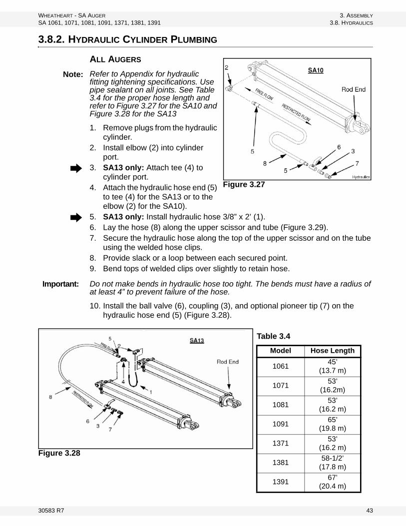
3.8.2. HYDRAULIC CYLINDER PLUMBING
ALL AUGERS
Refer to Appendix for hydraulic fitting tightening specifications. Use pipe sealant on all joints. See Table 3.4 for the proper hose length and refer to Figure 3.27 for the SA10 and Figure 3.28 for the SA13
1. Remove plugs from the hydraulic cylinder.
2. Install elbow (2) into cylinder port.
3. SA13 only: Attach tee (4) to cylinder port.
4. Attach the hydraulic hose end (5) to tee (4) for the SA13 or to the elbow (2) for the SA10).
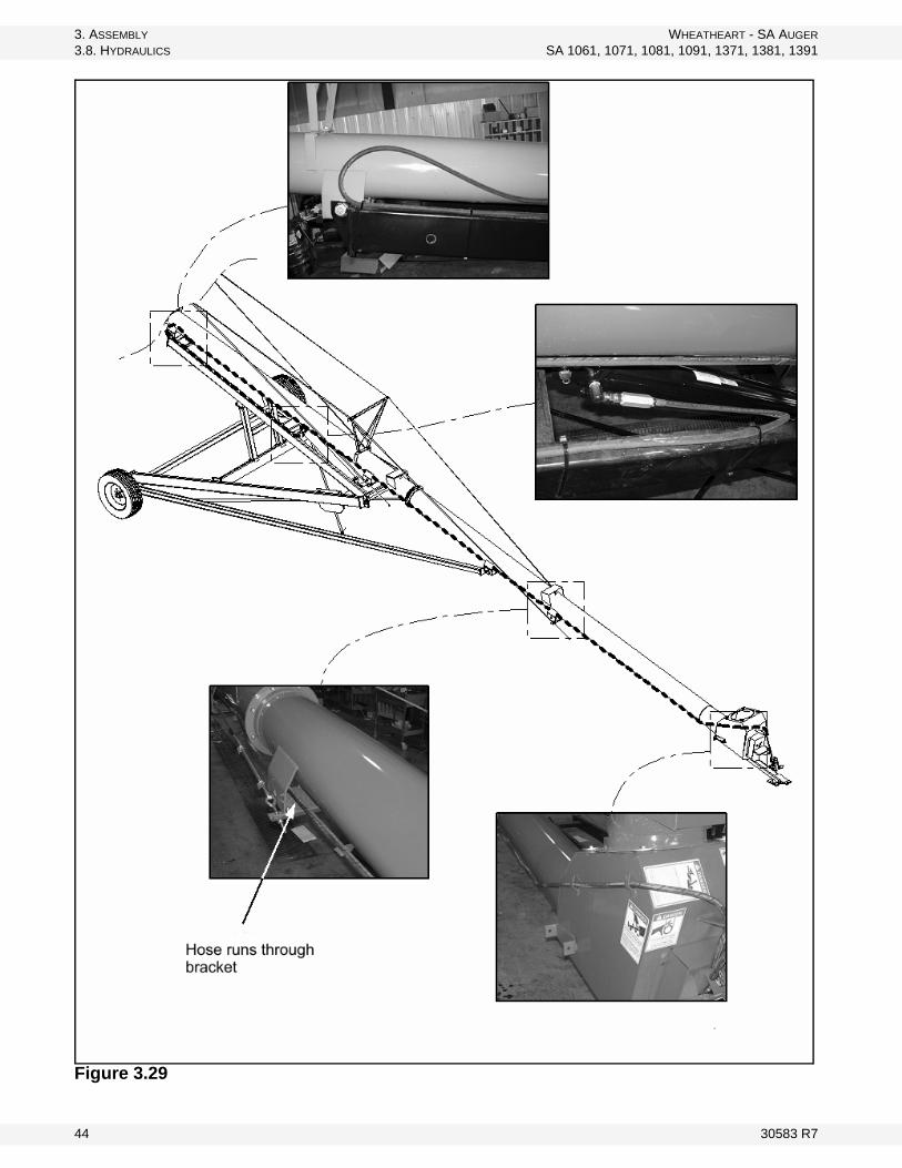
5. SA13 only: Install hydraulic hose 3/8” x 2’ (1).6. Lay the hose (8) along the upper scissor and tube (Figure 3.29). 7. Secure the hydraulic hose along the top of the upper scissor and on the tube
using the welded hose clips.8. Provide slack or a loop between each secured point. 9. Bend tops of welded clips over slightly to retain hose.
Do not make bends in hydraulic hose too tight. The bends must have a radius of at least 4” to prevent failure of the hose.
10. Install the ball valve (6), coupling (3), and optional pioneer tip (7) on the hydraulic hose end (5) (Figure 3.28).
Figure 3.28
Figure 3.27
Note:
Important:
Table 3.4
Model Hose Length
106145’
(13.7 m)
107153’
(16.2m)
108153’
(16.2 m)
109165’
(19.8 m)
137153’
(16.2 m)
138158-1/2’
(17.8 m)
139167’
(20.4 m)
30583 R7 43
3. ASSEMBLY WHEATHEART - SA AUGER
3.8. HYDRAULICS SA 1061, 1071, 1081, 1091, 1371, 1381, 1391
Figure 3.29
44 30583 R7

WHEATHEART - SA AUGER 3. ASSEMBLY
SA 1061, 1071, 1081, 1091, 1371, 1381, 1391 3.9. SWING AWAY COMPONENTS ASSEMBLY
3.9. SWING AWAY COMPONENTS ASSEMBLY
3.9.1. HOPPER ASSEMBLY
Note: The gearbox is sent from the factory filled half way with EP90 gear oil. Before further assembly, check oil level to make certain the gearbox is half full as required. Add oil If necessary. Do not use grease.
1. Attach the pivot-connector (1) to the appropriate holes (2) in the hopper with two 5/8” x 1-1/2” bolts (2) and 5/8” locknuts (2). DO NOT over-tighten; tighten snug only as these bolts act as pivot points (Figure 3.30).
2. Loosely secure the service door (3) with the 2 square latch-washers (4) and 3/8” locknuts (5) (Figure 3.30).
Note: These must be tightened securely after assembling hopper.
3. Clean dirt and paint from inside the u-joint and flighting shaft end, then insert a Woodruff key (6) (Figure 3.31).
4. Raise and support the hopper tube at about 50” under the spout. Open the service door on the hopper, then bring the tube and hopper together guiding the flight shaft into the u-joint (Figure 3.31).
5. Secure the tube to the pivot-connector on the hopper with eight 7/16” x 1” bolts (SA10) or twelve 7/16” x 1-1/4” bolts (SA13) and 7/16” locknuts.
6. Tighten set screws on u-joints, then close and secure the service door. 7. Attach the 2-piece rubber extension (7) to the inside of the hopper lip with
5/16” x 3/4” bolts (8), washer locknuts (9), and flat iron straps (10) provided plus the 2 piece extension connector plates (11) (Figure 3.30).
Note: To attach the rubber extension to the end of the hopper, remove the two 5/16” washer locknuts that secure the chain drive shield.
8. Attach the 4 pneumatic wheels (12) to the 4 hopper corners with the axle pins (13) and hairpins (14). The offset portion of the wheel must rest against the hopper. You have a choice of 3 height settings (Figure 3.30).
9. To connect the intake hopper to the auger boot, the safety discharge door (15) must be opened. This door is held in place internally with 2 springs (16). To open, pull the door down and then up and over the gearbox enclosure. Hold the door open with a C-clamp vise grip (17) (Figure 3.30).
WARNING
Components are heavy and create a crushing hazard if improperly handled. Be sure to use proper hoisting equipment and procedures, and ensure lifting apparatus is secure. Lockout the lifting apparatus before working around or under the raised components. Failure to do so may cause serious personal injury.
30583 R7 45

3. ASSEMBLY WHEATHEART - SA AUGER
3.9. SWING AWAY COMPONENTS ASSEMBLY SA 1061, 1071, 1081, 1091, 1371, 1381, 1391
10. Check that the u-joint spline and splined shaft on the lower gear box are clean, then apply a light film of grease on this splined shaft (Figure 3.30).
11. As the intake hopper is lowered onto the boot, the splined universal joint must be guided onto the splined shaft. Once positioned, the swivel ring should be resting flat on the boot surface and inside the 4 spacer nuts.
12. Install 4 large washers (20) with 3/8” x 3/4” bolts (21) to keep the intake hopper in place on the boot (Figure 3.32).
13. Lubricate the universal joint and then close the safety discharge door. Important: Keep it closed during operation.
Figure 3.30
Figure 3.31
Figure 3.32
46 30583 R7
WHEATHEART - SA AUGER 3. ASSEMBLY
SA 1061, 1071, 1081, 1091, 1371, 1381, 1391 3.9. SWING AWAY COMPONENTS ASSEMBLY
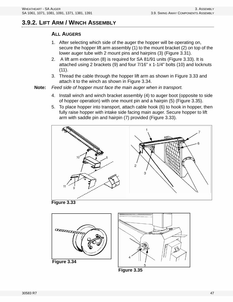
3.9.2. LIFT ARM / WINCH ASSEMBLY
ALL AUGERS
1. After selecting which side of the auger the hopper will be operating on, secure the hopper lift arm assembly (1) to the mount bracket (2) on top of the lower auger tube with 2 mount pins and hairpins (3) (Figure 3.31).
2. A lift arm extension (8) is required for SA 81/91 units (Figure 3.33). It is attached using 2 brackets (9) and four 7/16” x 1-1/4” bolts (10) and locknuts (11).
3. Thread the cable through the hopper lift arm as shown in Figure 3.33 and attach it to the winch as shown in Figure 3.34.
Note: Feed side of hopper must face the main auger when in transport.
4. Install winch and winch bracket assembly (4) to auger boot (opposite to side of hopper operation) with one mount pin and a hairpin (5) (Figure 3.35).
5. To place hopper into transport, attach cable hook (6) to hook in hopper, then fully raise hopper with intake side facing main auger. Secure hopper to lift arm with saddle pin and hairpin (7) provided (Figure 3.33).
Figure 3.33
Figure 3.34
Figure 3.35
30583 R7 47

3. ASSEMBLY WHEATHEART - SA AUGER
3.10. FINAL ASSEMBLY SA 1061, 1071, 1081, 1091, 1371, 1381, 1391
3.10. FINAL ASSEMBLY
3.10.1. PTO DRIVELINE
ALL AUGERS – FIGURE 3.36
1. Clean paint or dirt off of PTO driveline and flighting shaft ends before assembly. 2. Slide plain end of PTO driveline onto flighting shaft. Make sure that the 5/16” diameter holes for the roll pin (SA10) or 3/8” holes (SA13) are lined up.3. Carefully tap in a 5/16” roll pin (SA10) or 3/8” roll pin (SA13). Tighten the set screw.4. Install the sprocket shield (8) on the boot using four 5/16” x 3/4” bolts (9). 5. Slide the PTO transport saddle (10)
through the support strap (11) on the boot and rest the PTO driveline in it.
3.11. AUGER OPTIONS
3.11.1. REVERSER KIT ASSEMBLY
ALL AUGERS
1. Park the auger on level ground. Lower the auger to its full down position and remove the tractor from the auger. Chock the auger wheels to prevent rolling.
2. Remove cleanout plate and gearbox access cover from auger boot to gain access to bolts inside.
3. Remove PTO driveline from the auger. Remove the sprocket shield from the boot.
4. Remove the 3 locknuts on the lower bearing (1) (Figure 3.39).5. Loosen the 4th nut (2). (Figure 3.39)
6. SA 13 Augers: Replace the 3 bolts (1) with three 1/2” x 1-3/4” bolts (SA10), or 5/8” x 2” bolts (Figure 3.39).
7. SA 13 Augers: Knock steel plugs out of holes X and Y (Figure 3.37), using a punch and a hammer.
8. Position the reverser assembly over the bolts (1), install the nuts loosely on the threads (SA10-Figure 3.39, SA13-Figure 3.38).
Figure 3.36
48 30583 R7

WHEATHEART - SA AUGER 3. ASSEMBLY
SA 1061, 1071, 1081, 1091, 1371, 1381, 1391 3.11. AUGER OPTIONS
Figure 3.38 SA 10 Augers
The reverser sprocket must engage with the roller chain.
9. SA 10 Augers: Place the spacer (1/2” locknut) behind the reverser assembly (3), then loosely install the 5/16” x 1-1/4” bolt (3) and washer locknut. (Figure 3.39 and 3.40).
10. Adjust the roller chain tension, then tighten all bolts and nuts (1, 2, and 3). (Figure 3.39)
The SA13 augers require an extra 1/2 link installed.
11. Install the splined coupler onto the lower flighting shaft and square key. Secure with new 5/16” x 2” roll pin (Figure 3.40).
12. Install the new sprocket shield using four 5/16” x 3/4” bolts (Figure 3.40).
13. Attach PTO driveline saddle extension with one 7/16” x 1” bolt (SA10) or 5/8” x 1-1/2” (SA13) and locknut as shown (Figure 3.40).
14. SA 10 Augers: Fasten hitch extension to tow bar with one 3/4” x 2” bolt and 3/4” locknut. And one 5/8” x 4-1/2” bolt and 5/8” locknut (Figure 3.40).
15. SA13 Augers: Remove the two bolts securing the tow bar to the boot. Slide the tow bar out until the hole in the tow bar lines up with the reverser hole as shown in figure Figure 3.41. Reinstall the bolts and tighten securely.
Figure 3.37 SA 13 Augers
Figure 3.39 SA13 Augers
Note:
30583 R7 49

3. ASSEMBLY WHEATHEART - SA AUGER
3.11. AUGER OPTIONS SA 1061, 1071, 1081, 1091, 1371, 1381, 1391
16. Insert splined stub shaft with 1/4” x 1-1/2” square key (SA10) or 3/8” x 1-3/4” (SA13) into implement end of the PTO driveline and secure with a new 5/16” x 2” roll pin (SA10) or 3/8” x 2-1/2” (SA13). Tighten set screws securely (Figure 3.40).
Figure 3.40 SA10
50 30583 R7

WHEATHEART - SA AUGER 3. ASSEMBLY
SA 1061, 1071, 1081, 1091, 1371, 1381, 1391 3.11. AUGER OPTIONS
Figure 3.41 SA 13
3.11.2. RIGHT ANGLE DRIVE ASSEMBLY
ALL AUGERS
1. Park the auger on level ground. Lower the auger to its full down position and remove the tractor from the auger. Chock the auger wheels to prevent rolling.
2. Install the support leg. The pin must fit through the auger hitch clevis (Figure 3.43).
Note: Do not use support leg without pin in place.
3. Remove the hitch jack.4. Remove the sprocket shield from the boot.5. Remove the PTO driveline from the auger. When removing the roll pin protect
your eyes.Note: The gearbox is sent from the factory filled half way with EP90 gear oil. Before
further assembly, check oil level to make certain the gearbox is half full. Add oil if necessary. Do not use grease.
6. If necessary, adjust bottom drive chain so there is about 1/4” (0.64 cm) deflection by loosening the 4 bolts on the lower bearing, then retighten. (Oil the chain as required.)
7. Remove coupler chain from coupler sprockets on gearbox (Figure 3.42).8. Slide coupler sprocket onto the end of the flighting shaft (with existing square
key). Ensure outside face of sprocket is flush with the end of the shaft, then tighten the set screw (Figure 3.42).
30583 R7 51

3. ASSEMBLY WHEATHEART - SA AUGER
3.11. AUGER OPTIONS SA 1061, 1071, 1081, 1091, 1371, 1381, 1391
9. Position the gearbox mount assembly over the intake hitch tube straddling the jack mount tube (Figure 3.42). Position the jack mount below the gearbox mount assembly and below the tow bar.
10. For SA10, loosely install eight 7/16” x 4” bolts and 7/16” locknuts through the mount in the appropriate locations. For SA13, install two 5/8” x 6-1/2” bolts and 5/8” locknuts. Do not tighten (Figure 3.40).
11. Loosen the bolts securing the gearbox to adjust plate.12. Loosen the 5/8” adjust nut (Figure 3.42).13. Align the coupler sprockets by adjusting the gearbox horizontally and
vertically. Leave about 1/16” clearance between the sprockets for SA10 (Figure 3.42), and 3/8” clearance for SA13.
14. Tighten the bolts and locknuts holding the gearbox mount assembly to the intake hitch tube (Figure 3.42).
15. Recheck the coupler sprocket alignment and adjust if necessary.16. Tighten all gearbox and adjust plate bolt and nuts, also tighten set screws on
the sprockets (Figure 3.42).17. Install the coupler chain on the coupler sprockets and replace the sprocket
shield (Figure 3.42).18. Clean paint from the gearbox input shaft (Figure 3.46).19. Slide plain end of 60” non-separable PTO driveline onto the gearbox input
shaft. Use 1/4” x 1-1/2” square key (SA10) or 3/8” x 1-3/4” square key (SA13) and tighten set screws securely (Figure 3.46).
20. Install the transport saddle with halfband on the auger tube about 24” (61.0 cm) above the boot. Use 7/16” x 1-1/4” bolts and 7/16” locknuts (Figure 3.46).
21. Rotate transport saddle upwards or downwards until the PTO driveline clears the hopper winch handle. Tighten bolts. (Figure 3.46)
22. Slide shield assembly over PTO driveline, then attach to gearbox using two 1/2” x 1” bolts and 1/2” lock washers (Figure 3.43).
52 30583 R7

WHEATHEART - SA AUGER 3. ASSEMBLY
SA 1061, 1071, 1081, 1091, 1371, 1381, 1391 3.11. AUGER OPTIONS
Figure 3.44
Figure 3.43
Figure 3.42
SA130
SA80/100
SA130
SA100
30583 R7 53

3. ASSEMBLY WHEATHEART - SA AUGER
3.11. AUGER OPTIONS SA 1061, 1071, 1081, 1091, 1371, 1381, 1391
Figure 3.45 Gearbox Installed
Figure 3.46
54 30583 R7

WHEATHEART - SA AUGER 3. ASSEMBLY
SA 1061, 1071, 1081, 1091, 1371, 1381, 1391 3.11. AUGER OPTIONS
3.11.3. POWER SWING ASSEMBLY
ALL AUGERS
TO PREPARE AUGER FOR KIT INSTALLATION
1. With auger attached to tractor, park auger on level ground. Lower auger to full down position.
2. Fully lower swing hopper to the ground and swing it out onto a level surface.3. Shut down and lock out tractor power.
AXLE ASSEMBLY
1. Attach lower plate of the jack assembly to the axle using two 7/16” x 1" bolts and locknuts as shown in Figure 3.47 and Figure 3.48.
2. The chain guard can be removed for easier attachment of the jack. Ensure that the guard is in place and secure before operating.
3. Loosely attach stabilizer arms to axle assembly, using two 7/16” x 1" bolts and locknuts. The stabilizer arms attach to the outside of axle endplates (Figure 3.48).
TUBE ASSEMBLY
1. Close to where the end of swing tube joins with the hopper:
• place jack bracket with half clamp onto tube (Figure 3.48) • loosely secure these half-rings with two 7/16” x 1" bolts and locknuts • ensure ring is positioned so that the jack bracket is vertical, with the safety
decal being on top (Figure 3.42)2. Adjust jack to approximately 1" (2.54 cm) above its lowest setting (Figure
3.46). • Attach the jack to the jack bracket using the correct hole in upper plate
(Figure 3.46). • Use a 1/2” x 1" bolt and locknut, and tighten only enough to allow the jack
to pivot.
Figure 3.47
Figure 3.48
30583 R7 55

3. ASSEMBLY WHEATHEART - SA AUGER
3.11. AUGER OPTIONS SA 1061, 1071, 1081, 1091, 1371, 1381, 1391
3. Allowing wheels to touch the ground, slide the jack bracket close to the measurement “A,” indicated in Figure 3.48. Tighten the jack bracket with half clamp in place.
4. Loosely attach other end of the stabilizer arms to stabilizer bracket. 5. Secure the control valve to the valve bracket using bolts and locknuts
provided. 6. Secure the control valve assembly to the swing tube using two 7/16” x 1"
bolts and locknuts. Before tightening, adjust the stabilizer bracket to the dimension “B” shown in Figure 3.48.
7. Attach the hose clip bracket onto the tube approximately 1' (0.31 m) – 2' (0.61 m) down from the discharge end of the tube, and feed the long hydraulic hoses through the hose clips. Connect long hoses to side ports of the single spool valve (Figure 3.48).
• Power swing/hydraulic winch combinations use a 3 spool valve (Figure 3.50 and Figure 3.51)
8. Secure the hose by bending the clips closed with a hammer. Hoses may be looped around the swing hopper discharge spout.
9. Connect the supplied short hydraulic hoses to the hydraulic control valve and hydraulic motor (Figure 3.48).
• Power swing/hydraulic winch combinations use a 3 spool valve, and longer 48” (1.23 m) hoses (Figure 3.50 and 3.51).
10. Determine the correct type of hydraulic couplers (not supplied) required for your tractor and attach these to the other end of the long hoses
56 30583 R7

WHEATHEART - SA AUGER 3. ASSEMBLY
SA 1061, 1071, 1081, 1091, 1371, 1381, 1391 3.11. AUGER OPTIONS
Figure 3.49
Important: Single spool valves only: Determine whether your hydraulic system is an open or closed system. For a closed system, install the 3/8” NPTF diverter plug that comes with the single spool control valve. For an open system do not install plug. See Figure 3.51 on page 58 for more details.
RELIEF VALVE (FOR CLOSED CENTER ONLY)
Note: In some cases, the control valve will squeal when it is in neutral position. To correct this, the relief valve will need to be adjusted. Instructions are given below.
An adjustable ball spring relief valve is standard on all RD-2575 valves. The standard factory setting is 1500 psi @ 12 gpm and 1200 F.
Other settings can be specified.Note: Attach a pressure gauge to the inlet hose when adjusting the pressure relief in
order to assure correct adjustment.
The relief pressure is adjusted by removing acorn nut and turning the adjusting screw. Turning the adjusting screw clockwise will increase the pressure and counterclockwise will decrease the pressure. Do not back out adjusting screw to the point that it falls out.
SEE Figure 3.50
30583 R7 57
3. ASSEMBLY WHEATHEART - SA AUGER
3.11. AUGER OPTIONS SA 1061, 1071, 1081, 1091, 1371, 1381, 1391
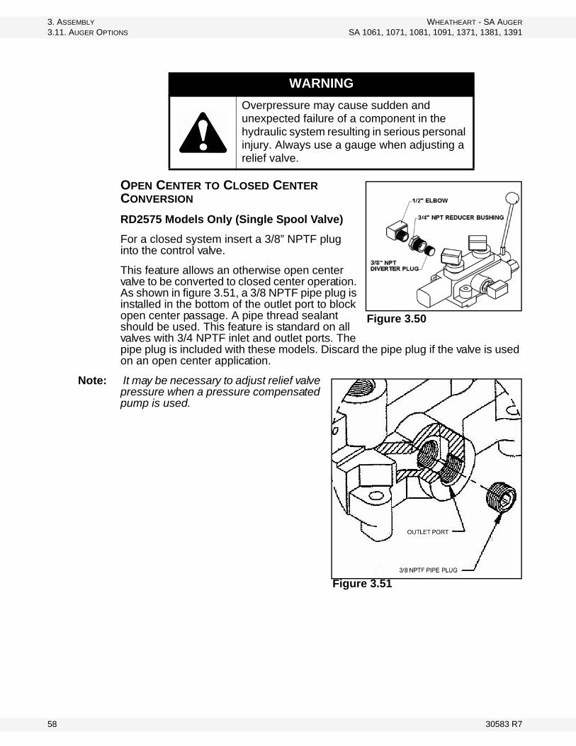
OPEN CENTER TO CLOSED CENTER CONVERSION
RD2575 Models Only (Single Spool Valve)
For a closed system insert a 3/8” NPTF plug into the control valve.
This feature allows an otherwise open center valve to be converted to closed center operation. As shown in figure 3.51, a 3/8 NPTF pipe plug is installed in the bottom of the outlet port to block open center passage. A pipe thread sealant should be used. This feature is standard on all valves with 3/4 NPTF inlet and outlet ports. The pipe plug is included with these models. Discard the pipe plug if the valve is used on an open center application.
Note: It may be necessary to adjust relief valve pressure when a pressure compensated pump is used.
WARNING
Overpressure may cause sudden and unexpected failure of a component in the hydraulic system resulting in serious personal injury. Always use a gauge when adjusting a relief valve.
Figure 3.50
Figure 3.51
58 30583 R7

WHEATHEART - SA AUGER 3. ASSEMBLY
SA 1061, 1071, 1081, 1091, 1371, 1381, 1391 3.11. AUGER OPTIONS
3.11.4. HYDRAULIC WINCH ASSEMBLY
ALL AUGERS
PREPARE AUGER FOR KIT INSTALLATION
1. With auger attached to tractor, park auger on level ground. Lower auger to full down position.
2. Fully lower swing hopper to ground and swing it out onto a level surface.3. Shut down and lock out tractor power.
WINCH ASSEMBLY (FIGURE 3.52)
1. Remove existing hand winch.2. Attach hydraulic winch to mount.3. Secure the control valve (9) to the valve bracket (11) using three 5/16” x
1-1/2” bolts and locknuts. Then secure this control valve assembly to the swing tube using two 7/16” x 1" bolts and locknuts. Rotate the half clamp so the valve handle is horizontal when the hopper is on the ground.
4. Inspect the existing winch cable on the hand winch for damage. Reuse if not damaged. Thread the cable through the lift arm pulleys and secure to the winch drum using the hardware provided.
5. Connect the supplied hydraulic hoses to the hydraulic control valve and hydraulic motor as shown below.
Note: Determine whether your hydraulic system is an open or closed system.For an open system do not install plug.For a closed system, install 3/8” NPT diverter plug that comes with the control valve (Figure 3.51).
6. Connect long hoses to side ports of the control valve. Hoses may be looped around the swing hopper discharge spout.
7. Determine the correct type of hydraulic couplers (not supplied) required for your tractor and attach these to the other end of the long hoses.
30583 R7 59

3. ASSEMBLY WHEATHEART - SA AUGER
3.11. AUGER OPTIONS SA 1061, 1071, 1081, 1091, 1371, 1381, 1391
Figure 3.52
Table 3.5
ITEM DESCRIPTION QTY
2 FTG,ELB,1/2”MNPT x 1/2”FNPSM 1
3 FTG,ELB,1/2”MNPT x 1/2”FNPSM,1/16“ORF 1
4 WINCH ASSY, DUT 2503 (W/MTR BRKT) 1
5 HOSE,HYD,3/8” x 158",6”FJIC x 1/2”MNPT 2
6 HOSE,HYD,3/8” x 173",1/2”M/MNPT 2
7 BOLT, 3/8” x 1” UNC GR5 PLD 2
8 NUT NYLOCK 3/8” UNC GR5 PLT 2
9 SINGLE SPOOL HYDRAULIC VALVE 1
10 HALF RING 1
11 MOUNT, SPOOL VLV 1
12 BOLT, 5/16” x 1-1/2” UNC GR5 PLD 3
13 NUT NYLOCK 5/16” UNC GR5 PLT 3
14 BOLT, 7/16” x 1” UNC GR5 PLD 2
15 NUT NYLOCK 7/16 “UNC GR5 PLT 2
16 FTG,STL,ELB,1/2”MNPT x 3/8”MJIC 2
60 30583 R7

WHEATHEART - SA AUGER 3. ASSEMBLY
SA 1061, 1071, 1081, 1091, 1371, 1381, 1391 3.11. AUGER OPTIONS
3.11.5. POWER SWING / HYDRAULIC WINCH COMBINATION
ALL AUGERS
TO PREPARE AUGER FOR POWER SWING / HYDRAULIC WINCH INSTALLATION
1. With auger attached to tractor, park auger on level ground. Lower auger to full down position.
2. Lower swing hopper fully to ground and swing it out onto a level surface.3. Shut down and lock out tractor power.
POWER SWING AXLE ASSEMBLY
1. Refer to Section 3.11.3. for assembly instructions.
POWER SWING AXLE & TUBE ASSEMBLY
1. Refer to Section 3.11.3. for assembly instructions.
HYDRAULIC WINCH ASSEMBLY
See Figure 3.50, and Figure 3.51.
1. Remove existing hand winch.2. Attach hydraulic winch to mount.3. Connect the 158” (4.01 m) hoses (32) from the hydraulic winch motor to the 3
spool valve.
Table 3.6
ITEM DESCRIPTION QTY
3 NUT NYLOCK 3/8 UNC GR5 PLT 2
25 VALVE, 3 SPOOL, NO HANDLES/FTGS 1
26 CONTROL LEVER, SD5 VALVE 2
27 HYD FIT ORIFICE 1/16”, 8MB-8FPx 1
28 FTG, STL, ELB45, 6MORBx6MJIC 4
29 FTG, STL,ELB,8MORBx1/2FNPSM 1
30 HOSE, HYD, 3/8 x 48",6FJIC x 1/2MNPT 2
31 BOLT, 5/16 x 2-1/2 UNC GR5 PLD 2
32 HOSE, HYD,3/8 x 158", 3/8MNPT x 1/2MNPT 2
33 HOSE,HYD, 3/8 x 173", 1/2M/MNPT 2
34 WINCH ASM, DUT 2503 (W/MTR BRKT) 1
35 BOLT, 3/8 x 1 UNC GR5 PLD 2
36 NUT NYLOCK 5/16 UNC GR5 PLT 2
30583 R7 61

3. ASSEMBLY WHEATHEART - SA AUGER
3.11. AUGER OPTIONS SA 1061, 1071, 1081, 1091, 1371, 1381, 1391
Figure 3.53
3.11.6. POWER SWING AND HYDRAULIC WINCH ADD ON KITS
HYDRAULIC WINCH ADD ON KIT TO POWER SWING
See Figure 3.53, 3.55, and 3.54.
1. Remove existing hand winch.2. Attach hydraulic winch to mount
(1.).3. Remove short hoses from the
power swing hydraulic motor to the single spool valve. Disconnect pressure and return hoses on the single spool valve.
4. Replace the single spool valve with the 3 spool valve provided.
5. Connect the 48” (1.23 m) hoses from the 3 spool valve to the power swing hydraulic motor.
33
Figure 3.54
62 30583 R7

WHEATHEART - SA AUGER 3. ASSEMBLY
SA 1061, 1071, 1081, 1091, 1371, 1381, 1391 3.11. AUGER OPTIONS
6. Connect the 158” (4.01 m) hoses from the winch hydraulic motor to the 3 spool valve (Figure 3.54).
7. Connect the 173” (4.39 m) hoses to the return and pressure side of the 3 spool valve.
Power Swing Add On Kit to Hydraulic Winch
See Figure 3.53, and 3.55.1. Disconnect
hoses from the existing single spool valve. Remove single spool valve.
2. Refer to Section 3.11.3. for power swing assembly.
3. Connect the existing hoses from the hydraulic winch to the 3 spool valve (Figure 3.55).
Note: Determine whether your hydraulic system is an open or a closed system. For an open system, do not install plug. For a closed system remove the open center plug located below the return port (Figure 3.51) with a #8 Allen wrench, and install the optional closed center plug (p/n 1600006-2) (ordered separately).
Figure 3.55
30583 R7 63

3. ASSEMBLY WHEATHEART - SA AUGER
3.11. AUGER OPTIONS SA 1061, 1071, 1081, 1091, 1371, 1381, 1391
64 30583 R7

WHEATHEART - SA AUGER 4. APPENDIX
SA 1061, 1071, 1081, 1091, 1371, 1381, 1391 4.1. BOLT TORQUE VALUES
4. Appendix
4.1. BOLT TORQUE VALUES
The tables shown below give correct torque values for various bolts and capscrews. Tighten all bolts to the torque specified in the chart unless otherwise noted. Check tightness of bolts periodically, using bolt torque chart as your guide. Replace hardware with the same strength bolt.
Figure 4.1 Pattern for Tightening Wheel Bolts
Table 4.1 Imperial Bolt Torque
BOLT DIAMETER
(Nm) (lb-ft) (Nm) (lb-ft) (Nm) (lb-ft)
1/4" 8 6 12 9 17 125/16" 13 10 25 19 36 273/8" 27 20 45 33 63 45
7/16" 41 30 72 53 100 751/2" 61 45 110 80 155 115
9/16" 95 60 155 115 220 1655/8" 128 95 215 160 305 2203/4" 225 165 390 290 540 4007/8" 230 170 570 420 880 6501" 345 225 850 630 1320 970
30583 R7 65

4. APPENDIX WHEATHEART - SA AUGER
4.2. TIGHTENING FLARE TYPE TUBE FITTINGS SA 1061, 1071, 1081, 1091, 1371, 1381, 1391
Torque figures indicated above are valid for non-greased or non-oiled threads and head unless otherwise specified. Therefore, do not grease or oil bolts or capscrews unless otherwise specified in this manual. When using locking elements, increase torque values by 5%.
4.2. TIGHTENING FLARE TYPE TUBE FITTINGS
1. Check flare and flare seat for defects that might cause leakage.2. Align tube with fitting before tightening.3. Lubricate connection and hand tighten swivel until snug.4. To prevent twisting the tube(s), use two wrenches. Place one wrench on the
connector body and with the second tighten the swivel nut to the torque shown.
Table 4.2 Metric Bolt Torque
BOLT DIAMETER (Nm) (lb-ft) (Nm) (lb-ft)M3 0.5 0.4 1.8 1.3M4 3 2.2 4.5 3.3M5 6 4 9 7M6 10 7 15 11M8 25 18 35 26M10 50 37 70 52M12 90 66 125 92M14 140 103 200 148M16 225 166 310 229M20 435 321 610 450M24 750 553 1050 774M30 1495 1103 2100 1550M36 2600 1917 3675 2710
Table 4.3 Flare Type Tube Fittings
Tube Size OD (in.)
Nut Size Across Flats
(in.)
Torque
Values(N-m)aTorque Values
(lb-ft)# of Turns to
Tighten (Flats)
(After Finger Tightening)
(Turn)3/16 7/16 8 6 1 1/61/4 9/16 12 9 1 1/6
5/16 5/8 16 12 1 1/63/8 11/16 24 18 1 1/61/2 7/8 46 34 1 1/65/8 1 62 46 1 1/63/4 1 1/4 102 75 3/4 17/8 1 3/8 122 90 3/4 1
a. * The torque values shown are based on lubricated connections as in reassemble.
66 30583 R7

WHEATHEART - SA AUGER 4. APPENDIX
SA 1061, 1071, 1081, 1091, 1371, 1381, 1391 4.3. TIGHTENING O-RING FITTINGS
4.3. TIGHTENING O-RING FITTINGS
1. Inspect o-ring and seat for dirt or obvious defects.2. On the angle fittings, back the lock nut off until washer bottoms out at top of
groove.3. Hand-tighten fitting until back up washer or washer face (if straight fitting)
bottoms on face and o-ring is seated.4. Position angle fittings by unscrewing no more than one turn.5. Tighten straight fittings to torque shown.6. Tighten while holding body of fitting with a wrench.
Table 4.4 “O” Ring FittingsTube Size OD (in.)
Nut Size Across Flats (in.)
Torque
Valuesa (Nm)
Torque
Valuesa (Lb-ft)# of Turns to
Tighten (Flats)(After Finger
Tightening) (Turn)
3/8 1/2 8 6 2 1/37/16 9/16 12 9 2 1/31/2 5/8 16 12 2 1/3
9/16 11/16 24 18 2 1/33/4 7/8 46 34 2 1/37/8 1 62 46 1-1/2 1/4
1-1/16 1-1/4 102 75 1 1/61-3/16 1-3/8 122 90 1 1/61-5/16 1-1/2 142 105 3/4 1/81-5/8 1-7/8 190 140 3/4 1/87/8 2-1/8 217 160 1/2 1/12
a. The torque values shown are based on lubricated connections as in reassemble.
30583 R7 67

4. APPENDIX WHEATHEART - SA AUGER
4.3. TIGHTENING O-RING FITTINGS SA 1061, 1071, 1081, 1091, 1371, 1381, 1391
68 30583 R7

LIMITED WARRANTYWheatheart warrants to the buyer that the new machinery is free from defects in material and workmanship.
This warranty is only effective for any new machinery that has not been altered, changed, repaired, or treated since its delivery to the buyer, other than by Wheatheart or its authorized dealers or employees, and does not apply to accessories, attachments, tools, or parts sold or operated with the new machinery if they have not been manufactured by Wheatheart.
Wheatheart shall only be liable for defects in the material or workmanship attributed to faulty material or bad workmanship that can be proved by the buyer, and specifically excludes liability for repairs arising as a result of normal wear and tear of the new machinery or in any other man-ner whatsoever, and without limiting the generality of the foregoing, excludes application or installation of parts not completed in accordance with Wheatheart operation manual, specifica-tions, or printed instructions.
A Warranty Registration Form and Inspection Report must be completed at the time of delivery and returned to Wheatheart Manufacturing within thirty (30) days.
Warranty Period
Defective parts are subject to inspection by a Wheatheart representative prior to approval of a warranty claim. All returned parts must be sent to the factory, freight pre-paid, in order to qualify for warranty replacement. Repaired or replaced parts will be returned freight collect.
If these conditions are fulfilled, Wheatheart shall at its own cost and its own option either repair or replace any defective parts provided that the buyer shall be responsible for all expenses incurred as a result of repairs, labor, parts, transportation, or any other work, unless Wheatheart has authorized such expenses in advance. Normal wear and service items such as belts, hoses, flashing, etc. are excluded from warranty.
The warranty shall not extend to any repairs, changes, alterations, or replacements made to the new equipment other than by Wheatheart or its authorized dealers or employees.
This warranty extends only to the original owner of the new equipment.
This warranty is limited to the terms stated herein and is in lieu of any other warranties whether expressed or implied, and without limiting the generality of the foregoing, excluded all warran-ties, expressed or implied, or conditions whether statutory or otherwise as to quality and fitness for any purpose of the new equipment, Wheatheart disclaims all liability for incidental or conse-quential damages.
This machine is subject to design changes and Wheatheart shall not be required to retro-fit or exchange items on previously sold units except at its own option.
WARRANTY VOID IF NOT REGISTERED
Private Farm Use One (1) year from date of purchase.
Commercial, Custom, or Rental Use Ninety (90) days from date of purchase.
Replacement Parts Ninety (90) days from date of replacement

Wheatheart
Part of the Ag Growth International Inc. Group
P.O. Box 39
Rosenort, Manitoba, Canada R0G 1W0
Phone: (866) 467-7207 (Canada & USA)
Fax: (866) 768-4852
website: www.wheatheart.com
email: [email protected]
© Ag Growth International Inc. 2013
Printed In Canada


