
X-RAY RADIOGRAPHY OF AISI 4340-2205 STEELS …mit.imt.si/Revija/izvodi/mit161/caligulu.pdf · u....
7
U. CALIGULU et al.: X-RAY RADIOGRAPHY OF AISI 4340-2205 STEELS WELDED BY FRICTION WELDING 39–45 X-RAY RADIOGRAPHY OF AISI 4340-2205 STEELS WELDED BY FRICTION WELDING RENTGENSKI PREGLED JEKEL AISI 4340-2205, VARJENIH S TRENJEM Ugur Caligulu 1 , Mahmut Yalcinoz 2 , Mustafa Turkmen 3 , Serdar Mercan 4 1 Firat University, Faculty of Technology, Dept. of Met. and Materials Eng., Elazig, Turkey 2 Firat University, Faculty of Technical Education, Dept. of Metallurgy Education, Elazig, Turkey 3 Kocaeli University, Hereke Vocational School, 41800 Kocaeli, Turkey 4 Cumhuriyet University, Faculty of Technology, Dept. of Mechatronic Eng., Sivas, Turkey ucaligulu@firat.edu.tr Prejem rokopisa – received: 2014-08-25; sprejem za objavo – accepted for publication: 2015-03-04 doi:10.17222/mit.2014.211 In this study, X-ray radiographic tests of friction-welded AISI 4340-AISI 2205 steels were investigated. AISI 4340 tempered steel and AISI 2205 duplex stainless steel, each of 12 mm diameter, were used to fabricate the joints. The friction-welding tests were carried out using a direct-drive-type friction-welding machine for different parameters. After this process, the radiographic tests of the welded joints were examined by X-ray diffraction. The experimental results indicated that the AISI 4340 tempered steel could be joined to the AISI 2205 duplex stainless steel using the friction-welding technique and for achieving a weld with sufficient strength. The result of the radiographic tests indicated that by increasing the rotation speed, the friction pressure and the forging pressure, the amount of flash increased for all the specimens. In contrast, when increasing the friction time the amount of flash decreased. The best properties for steels AISI 4340-2205 were observed for the specimens welded at a rotation speed of 2200 min –1 , a friction pressure of 40 MPa, a forging pressure of 80 MPa, a friction time of 6 s and a forging time of 3 s. Keywords: AISI 4340, AISI 2205, friction welding, radiographic test V tej {tudiji so bili rentgensko pregledani spoji jekel AISI 4340-AISI 2205, zvarjeni s trenjem. Spoji so bili izdelani s popu{~e- nim AISI 4340 jeklom in AISI 2205 dupleks nerjavnim jeklom, vsako premera 12 mm. Preizkus varjenja s trenjem je bil izvr{en z uporabo neposredno gnanega stroja za varjenje s trenjem, pri razli~nih parametrih. Po tem postopku so bili zvarjeni spoji pregledani z rentgenom. Rezultati preizkusov so pokazali, da je z varjenjem s trenjem mogo~e spojiti AISI 4340 popu{~eno jeklo in AISI 2205 dupleks nerjavno jeklo in da je mogo~e dobiti zvar z zadostno trdnostjo. Rezultati rentgenskih preiskav so pokazali, da pri nara{~ajo~i hitrosti vrtenja, tornega tlaka in tlaka pri kovanju dele` zmeh~anega roba nara{~a pri vseh vzorcih. Nasprotno pa se pri podalj{anju ~asa trenja zmanj{a koli~ina zmeh~anega roba. Najbolj{e lastnosti pri jeklih AISI 4340-2205 so bile opa`ene pri vzorcih, varjenih z rotacijo 2200 min –1 , tornim tlakom 40 MPa, kova{kim tlakom 80 MPa, ~asom trenja 6 s in ~asom kovanja 3 s. Klju~ne besede: AISI 4340, AISI 2205, varjenje s trenjem, rentgensko testiranje 1 INTRODUCTION Duplex stainless steel (DSS) is well known for its excellent strength and corrosion resistance. However, joining DSS plates by fusion welding causes a sig- nificant reduction in the mechanical properties, because of microstructure changes during weld solidification. It is essential to maintain the characteristics of the weld zone to use DSS in servicing highly critical environ- ments, such as ocean-mining machinery, oil and gas pipe lines, desalination plants and chemical tankers of ships, etc. DSS has ferrite (a) and austenite (g) in approxi- mately equal proportions, which possess body centered cubic (BCC) and face centered cubic structure (FCC), respectively. 1 During the controlled alloying process of the DSS, under equilibrium conditions, ferrite-promoting elements (Cr, Mo, Mn, W, Nb, Si, Ti and V) will con- centrate by diffusing in the ferrite. At the same time, austenite-promoting elements (Ni, C, N, Co and Cu) will concentrate by diffusing in the austenite phases. This gives the formation of a dual-phase microstructure. 2,3 But the welding of DSS forces the microstructure to remain in an excessive ferritic nature, because of the higher amounts of ferrite promoting elements in its chemical composition, and also due to a faster cooling rate. Austenite usually nucleates in the temperature range 1200–900 °C. During cooling, the weld zone remains in this temperature range for a very short period of time, i.e., from 4 s to 15 s. Thus, the arc energy and filler metal composition play a major role in the microstruc- tural stability after welding. 4 Tempered types of steel are machinery manufactured steels with and without alloy, whose chemical composi- tions, especially in terms of carbon content, are suitable for hardening and which show high toughness under a specific tensile strength at the end of the tempering process. Tempered types of steel, due to their superior mechanical properties, acquired at the end of the temper- ing process, are used in a wide range of areas, including the manufacture of parts such as various machine and engine parts, forging parts, various screws, nuts and stud Materiali in tehnologije / Materials and technology 50 (2016) 1, 39–45 39 UDK 669.14:621.791.1:620.179.152 ISSN 1580-2949 Original scientific article/Izvirni znanstveni ~lanek MTAEC9, 50(1)39(2016)
Transcript of X-RAY RADIOGRAPHY OF AISI 4340-2205 STEELS …mit.imt.si/Revija/izvodi/mit161/caligulu.pdf · u....
U. CALIGULU et al.: X-RAY RADIOGRAPHY OF AISI 4340-2205 STEELS WELDED BY FRICTION WELDING39–45
X-RAY RADIOGRAPHY OF AISI 4340-2205 STEELS WELDED BYFRICTION WELDING
RENTGENSKI PREGLED JEKEL AISI 4340-2205, VARJENIHS TRENJEM
Ugur Caligulu1, Mahmut Yalcinoz2, Mustafa Turkmen3, Serdar Mercan4
1Firat University, Faculty of Technology, Dept. of Met. and Materials Eng., Elazig, Turkey2Firat University, Faculty of Technical Education, Dept. of Metallurgy Education, Elazig, Turkey
3Kocaeli University, Hereke Vocational School, 41800 Kocaeli, Turkey4Cumhuriyet University, Faculty of Technology, Dept. of Mechatronic Eng., Sivas, Turkey
Prejem rokopisa – received: 2014-08-25; sprejem za objavo – accepted for publication: 2015-03-04
doi:10.17222/mit.2014.211
In this study, X-ray radiographic tests of friction-welded AISI 4340-AISI 2205 steels were investigated. AISI 4340 temperedsteel and AISI 2205 duplex stainless steel, each of 12 mm diameter, were used to fabricate the joints. The friction-welding testswere carried out using a direct-drive-type friction-welding machine for different parameters. After this process, the radiographictests of the welded joints were examined by X-ray diffraction. The experimental results indicated that the AISI 4340 temperedsteel could be joined to the AISI 2205 duplex stainless steel using the friction-welding technique and for achieving a weld withsufficient strength. The result of the radiographic tests indicated that by increasing the rotation speed, the friction pressure andthe forging pressure, the amount of flash increased for all the specimens. In contrast, when increasing the friction time theamount of flash decreased. The best properties for steels AISI 4340-2205 were observed for the specimens welded at a rotationspeed of 2200 min–1, a friction pressure of 40 MPa, a forging pressure of 80 MPa, a friction time of 6 s and a forging time of 3 s.Keywords: AISI 4340, AISI 2205, friction welding, radiographic test
V tej {tudiji so bili rentgensko pregledani spoji jekel AISI 4340-AISI 2205, zvarjeni s trenjem. Spoji so bili izdelani s popu{~e-nim AISI 4340 jeklom in AISI 2205 dupleks nerjavnim jeklom, vsako premera 12 mm. Preizkus varjenja s trenjem je bil izvr{enz uporabo neposredno gnanega stroja za varjenje s trenjem, pri razli~nih parametrih. Po tem postopku so bili zvarjeni spojipregledani z rentgenom. Rezultati preizkusov so pokazali, da je z varjenjem s trenjem mogo~e spojiti AISI 4340 popu{~enojeklo in AISI 2205 dupleks nerjavno jeklo in da je mogo~e dobiti zvar z zadostno trdnostjo. Rezultati rentgenskih preiskav sopokazali, da pri nara{~ajo~i hitrosti vrtenja, tornega tlaka in tlaka pri kovanju dele` zmeh~anega roba nara{~a pri vseh vzorcih.Nasprotno pa se pri podalj{anju ~asa trenja zmanj{a koli~ina zmeh~anega roba. Najbolj{e lastnosti pri jeklih AISI 4340-2205 sobile opa`ene pri vzorcih, varjenih z rotacijo 2200 min–1, tornim tlakom 40 MPa, kova{kim tlakom 80 MPa, ~asom trenja 6 s in~asom kovanja 3 s.Klju~ne besede: AISI 4340, AISI 2205, varjenje s trenjem, rentgensko testiranje
1 INTRODUCTION
Duplex stainless steel (DSS) is well known for itsexcellent strength and corrosion resistance. However,joining DSS plates by fusion welding causes a sig-nificant reduction in the mechanical properties, becauseof microstructure changes during weld solidification. Itis essential to maintain the characteristics of the weldzone to use DSS in servicing highly critical environ-ments, such as ocean-mining machinery, oil and gas pipelines, desalination plants and chemical tankers of ships,etc. DSS has ferrite (�) and austenite () in approxi-mately equal proportions, which possess body centeredcubic (BCC) and face centered cubic structure (FCC),respectively.1 During the controlled alloying process ofthe DSS, under equilibrium conditions, ferrite-promotingelements (Cr, Mo, Mn, W, Nb, Si, Ti and V) will con-centrate by diffusing in the ferrite. At the same time,austenite-promoting elements (Ni, C, N, Co and Cu) willconcentrate by diffusing in the austenite phases. Thisgives the formation of a dual-phase microstructure.2,3 But
the welding of DSS forces the microstructure to remainin an excessive ferritic nature, because of the higheramounts of ferrite promoting elements in its chemicalcomposition, and also due to a faster cooling rate.Austenite usually nucleates in the temperature range1200–900 °C. During cooling, the weld zone remains inthis temperature range for a very short period of time,i.e., from 4 s to 15 s. Thus, the arc energy and fillermetal composition play a major role in the microstruc-tural stability after welding.4
Tempered types of steel are machinery manufacturedsteels with and without alloy, whose chemical composi-tions, especially in terms of carbon content, are suitablefor hardening and which show high toughness under aspecific tensile strength at the end of the temperingprocess. Tempered types of steel, due to their superiormechanical properties, acquired at the end of the temper-ing process, are used in a wide range of areas, includingthe manufacture of parts such as various machine andengine parts, forging parts, various screws, nuts and stud
Materiali in tehnologije / Materials and technology 50 (2016) 1, 39–45 39
UDK 669.14:621.791.1:620.179.152 ISSN 1580-2949Original scientific article/Izvirni znanstveni ~lanek MTAEC9, 50(1)39(2016)

bolts, crank shafts, shafts, control and drive components,piston rods, various shafts, gears. For this reason, tem-pered steels are the type of steel used and produced atthe highest rate after unalloyed steels and constructionsteels. These steels constitute the most important part ofthe machinery-manufacturing steels. Generally, suchsteels are used for the production of fitting, axle shaft,the shaft and the gear.5–9
Friction welding is a solid-state joining process thatcan be used to join a number of different metals. Theprocess involves making welds in which one componentis moved relative to, and in pressure contact with, themating component to produce heat at the faying surfaces.Softened material begins to extrude in response to theapplied pressure, creating an annular upset. Heat isconducted away from the interfacial area for forging totake place. The weld is completed by the application of aforge force during or after the cessation of the relativemotion. The joint undergoes hot working to form ahomogenous, full surface, high-integrity weld. Frictionwelding is the only viable method in this field toovercome the difficulties encountered in the joining ofdissimilar materials with a wide variety of physicalcharacteristics. The advantages of this process are,among others, no melting, high reproducibility, shortproduction time and a low energy input.10–19
Welding technology is commonly used in manyareas. Because it is aimed to provide high and constantquality in manufacturing sector and in products, theimportance of non-destructive is the testing methods inquality-control strategies. Accordingly, the non-destruc-tive testing of welded joints has become a part of thetotal quality system.20,21 Being one of the most importantparts of quality control, non-destructive material testingmethod is the complementary part of the manufacturing.The non-destructive method is the common name fortesting methods through which the static and dynamicinformation about the materials are obtained by testingthe materials without damaging them. Thanks to thenon-destructive testing method, defects such as cracksoccurred during manufacturing or after used for a while,
space in internal structure, edge reduction, etc., are de-tected (Table 1).
The methods applied in non-destructive testing arevisual testing, liquid-penetrant testing, eddy-currenttesting, magnetic particle inspection, ultrasonic inspec-tion and radiographic inspection.22
High-energy electromagnetic waves may penetrateinto many materials. The radiation penetrating a specificmaterial may affect the radiation-sensitive films that areput on the other side of the material. After the develop-ment of the films, the image of the inside of the materialis seen. This image occurs because of the spaces in thematerial or thickness/density changes. This method iscalled radiographic testing, which is one of the oldestmethods of nondestructive testing and has been in use forapproximately five decades. Among the advantages ofthis method, compared to other methods, such as ultra-sound tests, is the formation of an internal šphotograph’of the material, which no other method is able to achieve.Various radiation sources may be used in radiographictesting. The radiographic testing of weld bead or castingpieces using X-rays or gamma source is one of the mostimportant uses for this inspection method. The energygap of the X-ray used in industrial radiography is gene-rally between 50 kV and 350 kV. The beam energy variesaccording to the type and thickness of the material. Inorder to get precise results from the testing, it has to bedone in accordance with the standards. These standardsare determined by considering the type of the materialand/or the type of product. There are also applicationstandards together with the standards according to whichthe acceptance levels are determined. The testing is doneby determining the standards suitable for the features ofthe product. Radiographic testing is generally appliedaccording to the EN 1435 or EN 12517 standards.23–25
The radiography method is applied to ferromagnetic,non-ferromagnetic metals and other all materials.Because X-ray provides the opportunity to analyze themicrostructure of the materials without making anydamage, it is widely used in non-destructive testing. ViaX-ray or gamma ray, thickness changes, structural
U. CALIGULU et al.: X-RAY RADIOGRAPHY OF AISI 4340-2205 STEELS WELDED BY FRICTION WELDING
40 Materiali in tehnologije / Materials and technology 50 (2016) 1, 39–45
Table 1: Non-destructive testing experiments in industrial areas37
Tabela 1: Neporu{ne preiskave na podro~ju industrijskih preiskav37
Practice Area Function Application ExamplesResearch andDevelopment
Structural evaluation of materials, Comparison ofproduction and assembly methods and evaluationfindings.
Examination of fatigue and microstructure of metalsand the detection of cracks in the welding seam.
ProductionControlMethod
Determination of the variable production method andto control.
Radiographic and ultrasonic thickness measuringmethod and determination of the manufacturingparameters.
QualityControl
Defective parts and the detection of abnormalities,Manufacturing assembly defects, place and method ofevaluation.
Poor adhesion, cracking in welding, metal in thenon-uniform pores and the determination of materialdefects.
During theserviceevaluation
Wear and use during the early identification ofabnormalities.
Corrosion in pipes and location of warehouses anddetection, Variety of early-warning systems invehicles.
changes, inner defects, montage details can bedetermined.26–30
The conventional method of inspection requires thatthe radiographic images are first-rate and are conse-quently controlled by international standards. However,radiographic inspection by inspectors is done subjec-tively and requires great experience, keenness of visionand knowledge of the techniques employed, and yet evenwhen done adequately, interpretation errors occurwhether it be the non-detection of a defect present or theincorrect classification of a detected defect.25,31–33 Theadvantages of the radiography method may be seen asfollows, the result is shown with an image, permanentrecords that may be seen outside of the test area can beobtained, the sensitivity is shown on every film and itmay be applied to any kind of material. As for the dis-advantages, they may be sorted as follows, it is notsuitable for thick pieces, may be harmful to health, directcalorie is needed for two-dimensional faults, the filmneeds posing and showing, is not suitable for automa-tion, surface defects, and it does not give informationabout the depth of the defect under the surface. Theequipment that is used is rather expensive in comparisonwith other methods and at most it needs careful workconcerning the radiation safety.34
In the present paper, X-ray radiographic testing ofAISI 4340-2205 steels welded by friction welding wereinvestigated.
2 MATERIALS AND METHODS
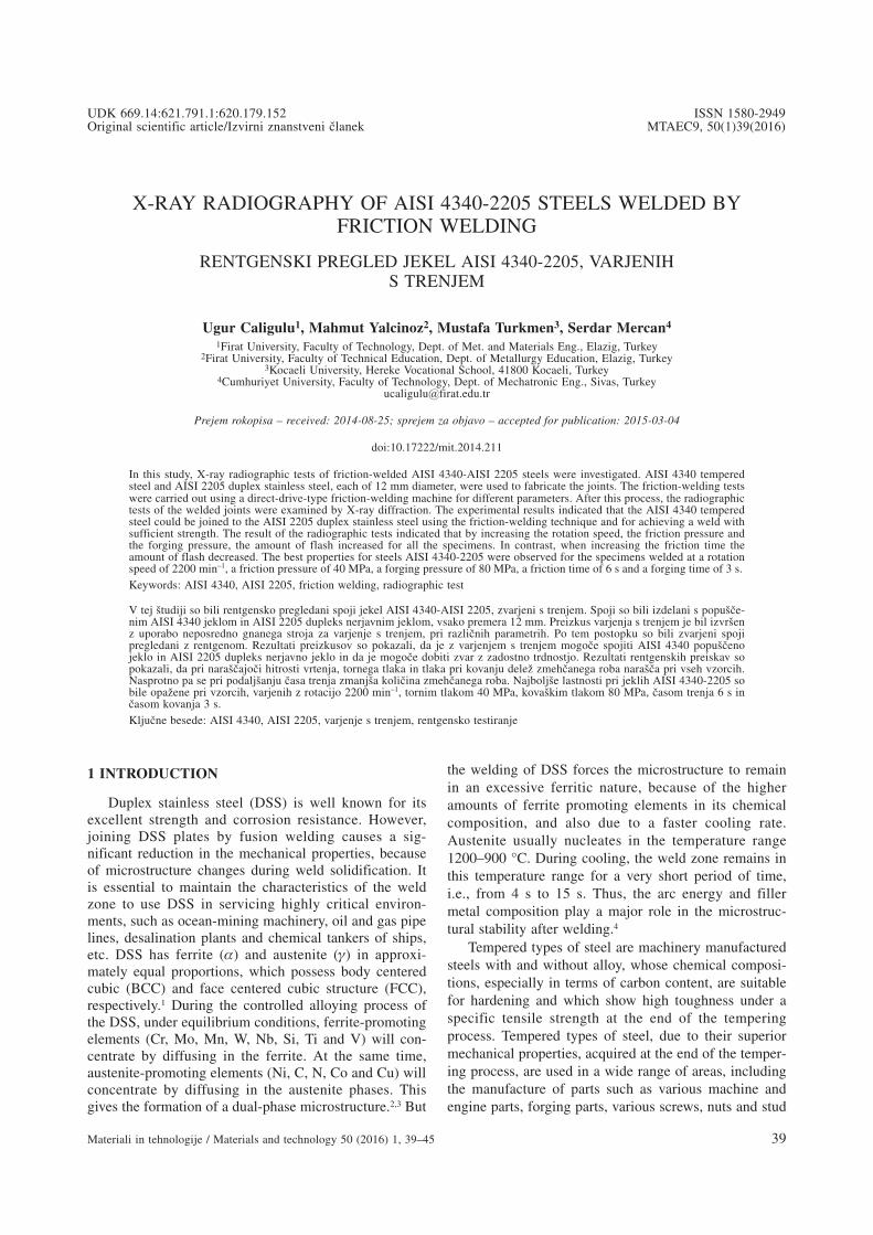
AISI 4340 tempered steel and AISI 2205 duplexstainless steel of 12 mm diameter were used to fabricatethe joints in this study. Table 2 illustrates the chemicalcompositions of the base metals. The friction-weldingtests were carried out using a direct-drive-type friction-welding machine. Table 3 has the mechanical propertiesand Table 4 has the physical properties of AISI 4340 andAISI 2205 steels. Table 5 illustrates the experimentalconditions. The experimental set-up is shown in Figure1.17
Table 4: Physical properties of copper and low carbon steelTabela 4: Fizikalne lastnosti bakra in malo oglji~nega jekla
Materials �(10-6)
�(W/m °C)
�(nΩ m)
E(GPa)
AISI 4340AISI 2205 14.7 19 85 200
�: Thermal Expansion Coefficient (20-800 °C)�: Thermal Conductive (20 °C)�: Electrical Resistance (20 °C)E: Elastic modulus (20 °C)
After the friction-welding procedure the specimenswere divided into sections transversely in order toinvestigate the microstructural variations from the centreto the outside of the weld. Transverse sections were pre-pared, and then grinding and polishing with 3-μm dia-mond paste were made in order to conduct a metallo-graphic examination of the joined materials. Thespecimens were etched in a chemical solution for AISI4340 2 % HNO3 + 98 % alcohol and in a solution forAISI 2205 25 % HNO3 + 75 % pure water to conduct themicrostructural examination (7.5 V + 30 s) The micro-structures of the joints were observed using lightmicroscopy (LM), the energy-dispersive spectroscopy(EDS) and X-ray diffraction (XRD). Microhardnessmeasurements were taken under a load of 50 g. Thetensile tests were conducted at room temperature with10–2 mm s–1 cross-head rate.
In controlling the weld seam, as the thickness is 4mm, radiographic testing was chosen from among the
U. CALIGULU et al.: X-RAY RADIOGRAPHY OF AISI 4340-2205 STEELS WELDED BY FRICTION WELDING
Materiali in tehnologije / Materials and technology 50 (2016) 1, 39–45 41
Table 2: Chemical compositions of test materialsTabela 2: Kemijska sestava preizkusnih materialov
MaterialsAlloy Elements (w/%)
C Mn Si P S Cr Mo Ni N CuAISI 4340 0.4 0.8 0.3 0.035 0.040 0.9 0.3 2.00 - -AISI 2205 0.018 1.686 0.309 0.026 0.003 22.333 3.379 4.932 0.191 0.097
Table 3: Mechanical properties of copper and low carbon steelTabela 3: Mehanske lastnosti bakra in malo oglji~nega jekla
Materials Tensile Strength(MPa)
Yield Strength 0.2 %(MPa)
Elongation(%)
Microhardness(HV)
AISI 4340 659 400 20.98 201AISI 2205 956 620 20 328
Figure 1: Experimental set-up17
Slika 1: Eksperimentalni sestav17
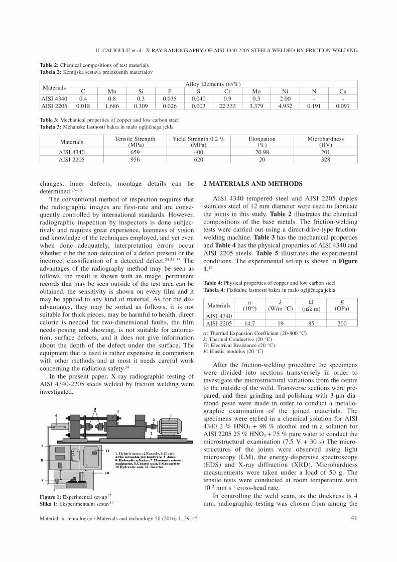
non-destructive methods and an X-ray tube was chosenas the radiation source. The principle can be seen in Fig-ure 2.35,36
Table 5: The process parameters used in the friction weldingTabela 5: Parametri procesa, uporabljeni pri varjenju s trenjem
Sampleno
Welding parameters
Rotatingspeed
(min–1)
Frictionpressure(MPa)
Forgingpressure(MPa)
Frictiontime(s)
Forgingtime(s)
Axialshort-ening(mm)
S1 2200 30 60 6 3 4.00S2 2200 30 60 10 5 4.37S3 2100 30 60 6 3 3.15S4 2100 30 60 10 5 3.41S5 2000 30 60 6 3 2.10S6 2000 30 60 10 5 2.80S7 2200 40 80 6 3 4.50S8 2200 40 80 10 5 4.78S9 2100 40 80 6 3 3.44
S10 2100 40 80 10 5 3.96S11 2000 40 80 6 3 2.20S12 2000 40 80 10 5 2.60
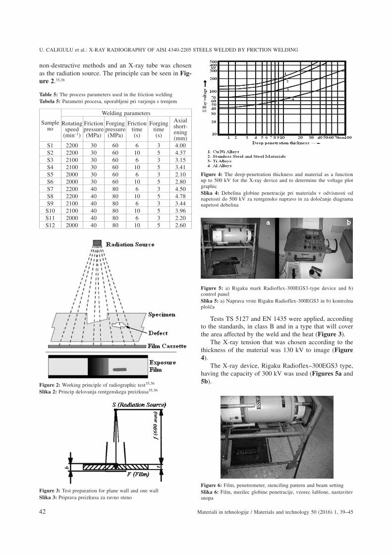
Tests TS 5127 and EN 1435 were applied, accordingto the standards, in class B and in a type that will coverthe area affected by the weld and the heat (Figure 3).
The X-ray tension that was chosen according to thethickness of the material was 130 kV to image (Figure4).
The X-ray device, Rigaku Radioflex–300EGS3 type,having the capacity of 300 kV was used (Figures 5a and5b).
U. CALIGULU et al.: X-RAY RADIOGRAPHY OF AISI 4340-2205 STEELS WELDED BY FRICTION WELDING
42 Materiali in tehnologije / Materials and technology 50 (2016) 1, 39–45
Figure 5: a) Rigaku mark Radioflex-300EGS3-type device and b)control panelSlika 5: a) Naprava vrste Rigaku Radioflex-300EGS3 in b) kontrolnaplo{~a
Figure 4: The deep-penetration thickness and material as a functionup to 500 kV for the X-ray device and to determine the voltage plotgraphicSlika 4: Debelina globine penetracije pri materialu v odvisnosti odnapetosti do 500 kV za rentgensko napravo in za dolo~anje diagramanapetost debelina
Figure 3: Test preparation for plane wall and one wallSlika 3: Priprava preizkusa za ravno steno
Figure 6: Film, penetremeter, stenciling pattern and beam settingSlika 6: Film, merilec globine penetracije, vzorec {ablone, nastavitevsnopa
Figure 2: Working principle of radiographic test35,36
Slika 2: Princip delovanja rentgenskega preizkusa35,36

C4 type, 100 × 240 mm2 Kodak film was used. Frontand back lead screens with a thickness of 0.125 mmwere used. The weld seam applied to the material withthe thickness of 4 mm was filmed by sending the beamto the pose diagram for 48 s. The distance between theX-ray device and film was 600 mm. The placement ofthe film is shown in Figure 6.37,38
3 RESULTS AND DISCUSSION
The flash obtained was symmetric, which indicatedplastic deformation on both the rotating and upsetting(reciprocating) side. The integrity of the joints was eva-luated for the friction-welded joints. The friction-pro-cessed joints were sectioned perpendicular to the bondline and observed through an optical microscope. It isclear that there were no cracks and voids in the weld
interface. From the microstructural observations, themicrostructures formed in the interface zone during orafter FW processes, there are three distinct zones acrossthe specimens identified as unaffected zone (UZ),deformed zone (DZ) and transformed and recrystallizedfully plastic deformed zone (FPDZ).39 Typical grainrefinement occurred in the DZ region by the combinedeffect of the thermal and mechanical stresses (Figure 7).A typical micrograph showing the different morpho-logies of the microstructure at different zones of thefriction-processed joint is shown in Figure 7.
According to the International Institute of Welding,welding defects and the explanations of the radiographicimages were defined as in Table 6.37,38 The films areplaced into the viewer shown in Figure 8 and the imageis evaluated according to Table 6. It was determined thatthe most common welding defects shown in Table 6have a lack of penetration according to the definitions ofwelding defects and the radiographic images (D) (S2). Inother samples the defects were not shown.
In Figure 9 the radiographic testing images of all thesamples are shown. The experimental results indicatedthat AISI 4340 tempered steel could be joined to AISI2205 duplex stainless steel using the friction-weldingtechnique and for achieving a weld with sufficientstrength. The result of the radiographic tests indicatedthat by increasing the rotation speed, friction pressureand forging pressure the amount of flash increased in allthe specimens. In contrast, when increasing the frictiontime the amount of flash decreased. The best propertiesof the AISI 4340-2205 steels were observed for the spe-cimens welded at a rotation speed of 2200 min–1, afriction pressure of 40 MPa, a forging pressure of 80
U. CALIGULU et al.: X-RAY RADIOGRAPHY OF AISI 4340-2205 STEELS WELDED BY FRICTION WELDING
Materiali in tehnologije / Materials and technology 50 (2016) 1, 39–45 43
Table 6: Definition of weld defects and radiographic image37,38
Tabela 6: Definicije napak zvarov in rentgenskih posnetkov37,38
A: Gas gapsAa: PorosityAb: Gas bubbles
Description * Because the captured gas bubbles are formed.* Gas channels or long gaps
RadiographicImage
* Sharp black shadows around the circle.* Sharp black depending on the round or the long shadows of the error change.
B: SlagBa: SlagBb: Slag errors
Description * Slag or other foreign materials during the welding.* Captured within gaps slag or foreign matter.
RadiographicImage
* Dark shadows or random shapes.* Continuous dark lines parallel to the seam edge welding.
C. InsufficientWelding
Description Between the main material source material during welding seam merger due to lackof two-dimensional error.
RadiographicImage
Sharp-edged thin dark line.
D. Insufficient DeepPenetration
Description Merger at the root welding of the lack of sewing filled fully with the welding orroot.
RadiographicImage
The middle of the dark seam continuous or discrete line welding.
E. CracksEa: Vertical CracksEb: HorizontalCracks
Description Local tensile strength of metal exceeded.RadiographicImage
Flat thin dark line.
F. Swelter Channel Description Welding material on the surface along the seam formed channel or groove.RadiographicImage
Weldings are spread wide and dark line along the seam.
Figure 7: Regions in which occurred microstructural changes39
Slika 7: Podro~ja, kjer se pojavijo spremembe v mikrostrukturi39

MPa, a friction time of 6 s and a forging time of 3 s(Figure 9).
4 CONCLUSIONS
In this study, X-ray radiographic testing of AISI 4340tempered steel and AISI 2205 duplex stainless steelwelded with friction welding were investigated. Thefollowing results were obtained.
• Friction-welding experiments were carried out usinga direct-drive-type friction-welding machine accord-ing to Table 5. This study concluded that the AISI4340 tempered steel could be joined succesfully toAISI 2205 duplex stainless steel using the friction-welding technique. The best joining was seen innumber S7. It was clear that the joining decreased inthe other samples.
• Comprehensive microstructural investigations for theAISI 4340-2205 steels’ friction-welded joints re-vealed that there were different regions at the weldinginterface, the wideness of fully plasticized deformedzone (FPDZ) decreases when rotational speed andfriction pressure increase.
• The larger microstructural changes take place in theHAZs. An increase in the contraction of the sampleswas observed after increasing the friction-weldingrotation speeds. The width of the HAZ is mainlyaffected by the friction time and rotation speed. Thisinfers that the width and formation of HAZs thatoccurred as a result of the reactions taking place atthe welding interface have an adverse effect on the
mechanical strength and, consequently, the quality ofthe friction-welded joints.
• It has been determined that the most common weld-ing defects shown in Table 6 have a lack of pene-tration according to the definitions of welding defectsand the radiographic images (D) (Sample No: 2). Inother samples there were no defects. The result of theradiographic tests indicated that by increasing therotation speed, the friction pressure and the forgingpressure the amount of flash increased in all thespecimens. In contrast, when increasing the frictiontime the amount of flash decreased. The best proper-ties of were AISI 4340-2205 steels observed for thespecimens welded at a rotation speed of 2200 min–1, afriction pressure of 40 MPa, a forging pressure of 80MPa, a friction time of 6 s and a forging time of 3 s(Figure 9).
• The highest deformation was always for the AISI4340 tempered steel side and in all samples theoriginal structure was preserved in the undeformedregion.
5 REFERENCES1 ASM Handbook on welding, vol. 6, ASM International Publisher,
1993, 471–4812 J. Charles, Duplex stainless steel, A Review, Proc. 7th Duplex Int.
Conf. & Expo, Grado, Italy, 20073 J. C. Lippold, D. J. Kotecki, Welding metallurgy and weldability of
stainless steels, Wiley-Interscience, 20054 A. V. Jebaraj, L. Ajaykumar, Microstructure analysis and the influ-
ence of shot peening on stress corrosion cracking resistance ofduplex stainless steel welded joints, Indian Journal of Engineering &Materials Sciences, 21 (2014), 155–167
5 S. D. Meshram, T. Mohandas, R. G. Madhusudhan, Friction weldingof dissimilar pure metals, Journal of Materials Processing Tech-nology, 184 (2008), 330–337, doi:10.1016/j.jmatprotec.2006.11.123
6 P. Sathiya, S. Aravindan, A. Noorul Haq, Some experimentalinvestigations on friction welded stainless steel joints, Materials andDesign, 29 (2008), 1099–1109, doi:10.1016/j.matdes.2007.06.006
7 S. Celik, I. Ersozlu, Investigation of the mechanical properties andmicrostructure of friction welded joints between AISI 4140 and AISI1050 steels, Mater. Design, 30 (2009), 970–976,doi:10.1016/j.matdes.2008.06.070
8 http://www.celmercelik.com.9 M. Sahin, H. E. Akata, An experimental study on friction welding of
medium carbon and austenitic stainless steel components, Indust.Lubricat. Tribol., 56 (2004) 2, 122–129, doi:10.1108/00368790410524074
10 M. Sahin, Evaluation of the joint interface properties of auste-nitic-stainless steels (AISI 304) joined by friction welding, Materialsand Design, 28 (2007), 2244–2250, doi:10.1016/j.matdes.2006.05.031
11 I. Kirik, N. Ozdemir, Weldability and joining characteristics of AISI420/AISI 1020 steels using friction welding, International Journal ofMaterials Research, 104 (2013) 8, 769–775, doi:10.3139/146.110917
12 N. Ozdemir, F. Sarsilmaz, A. Hascalik, Effect of rotational speed onthe interface properties of friction-welded AISI 304L to 4340 steel,Mater. Des., 28 (2007), 301–307, doi:10.1016/j.matdes.2005.06.011
13 Welding handbook, Welding Processes, Volume 2, Eighth edition,American Welding Society Inc., Miami 1997, 739–761
14 R. E. Chalmers, The Friction Welding Advantage, ManufacturingEngineering, 126 (2001), 64–65
U. CALIGULU et al.: X-RAY RADIOGRAPHY OF AISI 4340-2205 STEELS WELDED BY FRICTION WELDING
44 Materiali in tehnologije / Materials and technology 50 (2016) 1, 39–45
Figure 9: Radiographic test photographs of samples (S1 – S12)Slika 9: Rentgenski posnetki vzorcev (S1 – S12)
Figure 8: Film-examination device (Viewer)Slika 8: Naprava za pregled filma
15 N. Ozdemir, Investigation of the mechanical properties of friction-welded joints between AISI 304L and AISI 4340 steel as a functionrotational speed, Materials Letters, 55 (2005), 2504–2509,doi:10.1016/j.matlet.2005.03.034
16 D. E. Spindler, What Industry Needs to Know about FrictionWelding, Welding Journal, (1994), 37–42
17 I. Kirik, N. Ozdemir, U. Caligulu, Effect of particle size and volumefraction of the reinforcement on the microstructure and mechanicalproperties of friction welded MMC to AA 6061 aluminum alloy,Kovove Mater., 51 (2013) 4, 221–227, doi:10.4149/km_2013_4_221
18 I. Kirik, N. Ozdemir, F. Sarsilmaz, Microstructure and MechanicalBehaviour of Friction Welded AISI 2205/AISI 1040 Steel Joints,Materials Testing, 54 (2012) 10, 683–687, doi:10.3139/120.110379
19 M. B. Uday, M. N. Ahmad Fauzi, H. Zuhailawati, A. B. Ismail,Advances in friction welding process: a review, Science andTechnology of Welding and Joining, 15 (2010) 7, 534–558,doi:10.1179/136217110X12785889550064
20 M. Taskin, U. Caligulu, M. Türkmen, X-Ray Tests of AISI 430 and304 Stainless Steels and AISI 1010 Low Carbon Steel Welded byCO2 Laser Beam Welding, Materials Testing, 53 (2011) 11–12,741–747, doi:10.3139/120.110283
21 H. Dikbas, U. Caligulu, M. Taskin, M. Türkmen, X-Ray Radio-graphy of Ti6Al4V Welded by Plasma Tungsten Arc (PTA) Welding,Materials Testing, 55 (2013) 3, 197–202, doi:10.3139/120.110426
22 http://makina.ktu.edu.tr/static/lab_foy/lab21.doc23 http://www.wtndt.metu.edu.tr/ndt/tr/node/824 http://asalmakina.com/anasayfam.asp?sid=6&pid=425 R. R. da Silva, L. P. Calôba, M. H. S. Siqueira, J. M. A. Rebello,
Pattern recognition of weld defects detected by radiographic test,NDT&E International, 37 (2004) 6, 461–470, doi:10.1016/j.ndteint.2003.12.004
26 T. Tekiz, The Non-destructive Testings, ITU Faculty of MechanicalEngineering, Istanbul, 1984
27 M. Albayrak, The Control and Inspection of the Welding Seams,IGDAS, 1997
28 http://www.ndt-ed.org29 http://www.wtndt.metu.edu.tr30 TS EN 444, TS EN 462 Standards, 199431 K. Aoki, Y. Suga, Intelligent image processing for abstraction and
discrimination of defect image in radiographic film, Proceedings ofthe Seventh International Offshore and Polar Engineering Con-ference, Honolulu, USA, 1997, 527
32 A. Kehoe, G. A. Parker, Image processing for industrial radiographicinspection: image enhancement, Br J NDT, 32 (1990) 4, 183–190
33 Y. Cherfa, Y. Kabir, R. Drai, X-rays image segmentation for NDT ofwelding defects, 7th European Conference on Non DestructiveTesting, Copenhagen, 1998, 2782
34 C. R. Clayton, K. G. Martin, Conf. Proceedings High NitrogenSteels, The Institute of Metals, Lille, 1989, 256
35 S. Ekinci, The Evaluation of the Welding Seam Errors with DigitalRadiographic Methods, The Atom Energy Foundation of Turkey,Istanbul
36 The Certificate of Material Testing Knowledge, Eregli Iron and SteelPlants T.A.S
37 N. Ozakin, H. Baycik, The Radiographic Inspection of the WeldingSeam of the Body of Ship, The 4th Iron–Steel Congress, Karabuk,2007, 289
38 A. Topuz, The Non-destructive Inspections, YTU, Istanbul, 199339 S. Mercan, N. Ozdemir, A Couple of AISI 2205/AISI 1020 Material
Combination with Friction Welding Method, NWSA-TechnologicalApplied Sciences, 2A0080, 8 (2013) 2, 18–34, doi:10.12739/NWSA.2013.8.2.2A0080
U. CALIGULU et al.: X-RAY RADIOGRAPHY OF AISI 4340-2205 STEELS WELDED BY FRICTION WELDING
Materiali in tehnologije / Materials and technology 50 (2016) 1, 39–45 45


