<W?T -...
73
Carlsbad Field pmce ATS-14-628 01LC ONSEWK" ON Fomi3l60-3 (March 2012) UNITED STATES DEPARTMENT OF THE INTERIOR BUREAU OF LAND MANAGEMENT OCT 2 4 ZOH RECEIVED APPLICATION FOR PERMIT TO DRILL OR REENTER la. Type of work: 0DRILL •REENTER lb. Type of Well: \7\ Oil Well [~J Gas Well Qother [ 7 ] Single Zone [ ~ l Multiple Zone <W?T rUiAo /iron rn/io]* 2. Name of Operator Mewbourne Oil Company 3a. Address PO Box 5270 Hobbs, NM 88241 3b. Phone No. (include area cocky 575-393-5905 4. Location of Well (Report location clearly and in accordance with any State requirements.*) Al surface 145' FSL & 1980' FWL, Sec 12 T24S R26E At proposed prod, zone 330' FSL & 1980' FWL Sec 13 T24S R26E 14. Distance in miles and direction from nearest town or post office* 12.5 miles from Malaga, NM 15 Distance from proposed* location to nearest property or lease line, ft. (Also to nearest drig. unit line, ifany) 18. Distance from proposed location* U 5 f f M a v e r i c k 1 3 D M to nearest well, drilling, completed, .- . ~ „..,, applied for, on this lease, ft. F e d Com #1H 21. Elevations (Show whether DF, KDB, RT, GL, etc.) 3257' FORM APPROVED 0MB No. 1004-0137 Expires October 31, 2014 fit l0 5. Lease Serial No. NM 111528, NMLC 0065/421 6. If Indian. Allotee or Tribe Name 7 If Unil or CA Agreement, Name and No. 8. Lease Name and Well No. ^ Maverick 13 B2CN Fed Com #1H £. 3/3Y& > 9. API Well No. fija 4^BoneSpring/ /JJ6 st >/xS ll. Sec, T. R.'M. or Blifand Survey or Area Sec 12T24S R26E Vita 12. County or Parish Eddy 13. State NM 16. No. of acres in lease 360- NM 111528 1120-NMLC 0065421 19. Proposed Depth 7,087.0' - TVD 17. Spacing Unil dedicated to this well 160 20. BLM/BIA Bond No. on file NM-1693 Nationwide, NMB-000919 22 Approximate date work will start* 04/28/2014 23. Estimated duration 60 Days 24 Attachments The following, completed in accordance with the requirements of Onshore Oil and Gas Order No. 1, must be attached to this form: 1. Well plat certified by a regislered surveyor. 2. A Drilling Plan. 3. A Surface Use Plan (if the location is on National Forest System Lands, the SUPO must be filed with the appropriate Forest Service Office). 4. Bond to cover the operations unless covered by an existing bond onfile(see Item 20 above). 5. Operator certification 6. Such other siie specific information and/or plans as may be required by the BLM. 25. Signature ^-p A yj ft Name (Printed/Typed) Bradley Bishop Date 03/18/2014 Title II \ Approvedbyr% «eveCaffey Name (Printed/Typed) D 0CT 2 0 2014 FIELD MANAGER Office CARLSBAD FIELD OFFICE Application approval does not warrant or certify that the applicant holds legal or equitable title tolhose rights in ihe subject lease which would entitle the applicant to conduct operations thereon. . _ Conditions of approval, ifany, are attached. APPROVAL F O R T W O YEARS Title 18 U.S.C. Section 1001 and Title 43 U.S.C. Section 1212, make it a crime for any person knowingly and willfully to make to any department or agency ofthe United States any false,fictitiousor fraudulent statements or representations as to any matter within its jurisdiction. (Continued on page 2) Carlsbad Controlled Water Basin ''(Instructions on page 2) SEE ATTACHED FOR CONDITIONS OF APPROVAL Approval Subject to Genera! Requirements & Special Stipulations Attached
Transcript of <W?T -...

Carlsbad Field pmce ATS-14-628
0 1 L C O N S E W K " O N
Fomi3l60-3 (March 2012)
UNITED STATES DEPARTMENT OF THE INTERIOR BUREAU OF LAND MANAGEMENT
OCT 2 4 ZOH
RECEIVED
APPLICATION FOR PERMIT TO DRILL OR REENTER
la. Type of work: 0 D R I L L •REENTER
lb. Type of Well: \ 7 \ Oil Well [~J Gas Well Qother [ 7 ] Single Zone [ ~ l Multiple Zone
<W?T rUiAo /iron rn/io]*
2. Name of Operator Mewbourne Oil Company
3a. Address PO Box 5270 Hobbs, NM 88241
3b. Phone No. (include area cocky
575-393-5905
4. Location of Well (Report location clearly and in accordance with any State requirements.*)
Al surface 145' FSL & 1980' FWL, Sec 12 T24S R26E
At proposed prod, zone 330' FSL & 1980' FWL Sec 13 T24S R26E
14. Distance in miles and direction from nearest town or post office* 12.5 miles from Malaga, NM
15 Distance from proposed* location to nearest property or lease line, ft. (Also to nearest drig. unit line, ifany)
18. Distance from proposed location* U 5 f f M a v e r i c k 1 3 D M
to nearest well, drilling, completed, .- . ~ „..,, applied for, on this lease, ft. F e d Com #1H
21. Elevations (Show whether DF, KDB, RT, GL, etc.) 3257'
FORM APPROVED 0MB No. 1004-0137
Expires October 31, 2014
fit l0
5. Lease Serial No. NM 111528, NMLC 0065/421
6. If Indian. Allotee or Tribe Name
7 If Unil or CA Agreement, Name and No.
8. Lease Name and Well No. ^ Maverick 13 B2CN Fed Com #1H £. 3/3Y& >
9. API Well No.
fija4^BoneSpring/ /JJ6st>/xS
l l . Sec, T. R.'M. or Blifand Survey or Area
Sec 12T24S R26E
Vita
12. County or Parish
Eddy
13. State
NM
16. No. of acres in lease 360- NM 111528 1120-NMLC 0065421
19. Proposed Depth
7,087.0' - TVD
17. Spacing Unil dedicated to this well
160
20. BLM/BIA Bond No. on file
NM-1693 Nationwide, NMB-000919
22 Approximate date work will start*
04/28/2014
23. Estimated duration
60 Days
24 Attachments
The following, completed in accordance with the requirements of Onshore Oil and Gas Order No. 1, must be attached to this form:
1. Well plat certified by a regislered surveyor. 2. A Drilling Plan. 3. A Surface Use Plan (if the location is on National Forest System Lands, the
SUPO must be filed with the appropriate Forest Service Office).
4. Bond to cover the operations unless covered by an existing bond on file (see Item 20 above).
5. Operator certification 6. Such other siie specific information and/or plans as may be required by the
BLM.
25. Signature ^-p A y j ft Name (Printed/Typed) Bradley Bishop
Date 03/18/2014
Title II \
Approvedbyr%«eveCaffey Name (Printed/Typed) D0CT 2 0 2014
FIELD MANAGER Office
CARLSBAD FIELD OFFICE
Application approval does not warrant or certify that the applicant holds legal or equitable title tolhose rights in ihe subject lease which would entitle the applicant to conduct operations thereon. . _ Conditions of approval, ifany, are attached. A P P R O V A L F O R T W O Y E A R S
Title 18 U.S.C. Section 1001 and Title 43 U.S.C. Section 1212, make it a crime for any person knowingly and willfully to make to any department or agency ofthe United States any false, fictitious or fraudulent statements or representations as to any matter within its jurisdiction.
(Continued on page 2)
Carlsbad Controlled Water Basin
''(Instructions on page 2)
SEE ATTACHED FOR CONDITIONS OF APPROVAL
Approval Subject to Genera! Requirements & Special Stipulations Attached

Datrlctl 1«25 K. M i Dr., Hobbs, NM 88240 Phon«:(575)393.<l«l Fbt: (575) »3-0720 EMtidJI ell B Fink St, AiUn, MM 98210 Phone: (.SIS) 748-128J Fmc <?75) 748-9720 partem 1000 RJe BruoiRotlJ, ASM, NM 87410 Phone: (505) 334-6178 J/BC 003) 334-6170 PW>H TV 1220 B. a Fisneb Dr.. 8uU Fe, NM 8730! Phone: (505) 47«-34«0 File (!09>47<-34<2
State of New Mexico -Energy, Minerals & Natural Resources Department
OIL CONSERVATION DIVISION 1220 South St. Francis Dr.
Santa Fe, NM 87505
WELL LOCATION AND ACREAGE DEDICATION PLAT
Fonn C-102 Revised August 1,2011
Submit one copy to appropriate District Office
• AMENDED REPORT
'FodCtJe
WILDCAT eONE SPRING / OjeS/ Froptrty Codo
.3/383S ' 'PrwertyNMe
MAVERICK 13 B2CN FEDERAL COM IH 1 Operttar Hoiae
MEWBOURNE OIL COMPANY 'llnaflan
•! 3257' • Surface Location
N Section
12 , TewraAtp
24-S Hssge
26-E Lol Idn Feet fron the
145 NcrOVSraaittBC
SOUTH Feet from I
1980 Eot/Wcct Itac
WEST CwatJ
EDDY "Bi&i^Ho e Looatidnlf Different From Sutface
CLsr lo tu .
N
Section
13 ! TowniMp
;24-S
Rttage
26-E lol Idn Feetf
330
i (be North/Sen* Une
SOUTH
Feet Urom die
1980 Est/Wed Use
WEST
O n r f
EDDY 'Dtdccled Acrei
: 160
• Jtdat arlBflH ' Coneoil (teflon C« (It 'Order No.
No allowable will be assigned to this completion until all interests have been consolidated or a non-standard unit has been approved by the division.
- \ — —12 \ —<g
T
I I I
I si I
I II
m 1980
E 26f(!,98'«
*
3>
45'© J _ J
_PR03UCNG ARr-A
PROJECT (AREA
] 2
' GEODETIC DATA NAD 27 GRID - NM EAST
SURFACE LOCATION N 445533.0 E 526323.4
LAT: 32.22485B74- N LONG: 104.24820920" W
CORNER DATA NAD 27 GRID - NM EAST
A: CALCULATED CORNER N 44O103.0 - E 524398.9
8: FND BRASS CAP 1968 N 445406.1 - E 524345.7
C: FND BRASS CAP 196B N 448059.9 - E 524313.9
D: FN0 BRASS CAP 1968 N 450713.2 - E 524282.8
E: FND BRASS CAP 196B N 450685.5 - E 526973.3
F: FN0 BRASS CAP 1968 N 450657.6 - E 529663.2
G: FND BRASS CAP 196B N +48007.7 - E 529643.0
H: FND BRASS CAP 1968 N 445357.0 - E 529642.0
I: FND BRASS CAP 1968 N 442707.4 - E 529641.5
J: FND BRASS CAP 1968 N 440057.9 - E 529639.7
K: FND BRASS CAP 1968 N 440078.7 - E 527019.8
U FND BRASS CAP 1968 N 4453B2.0 - E 528994.0
"OPERATOR CERTIFICATION Jfrsrvfy orrtjfytfmtkg ttformoiKn ccrtairvd kinh ittnaanica^tda
.tothrtmt q/ny bttmim^panttalty.twMlllwathk agan^tanetl/ar
mm a wuMg ttOmt cr uimtntmml Mem to (At tant «Jui*g
thaprepaMdbmtatK&teBtknorhaafigktodrei&tswtlactiiis
Itoaxlcnpuimottoa eaemavahan mntr qfa/ttiamtnml orvar&n.
rtaMeLortQavcUtremypodingazrvmat waccKpultotypocitng
oniir htr&ofun e^rtd ty ttu drtbtcrt.
fngpttttuBpf
. Bradley. Bishop
"SURVEYOR CERTIFICATION I hereby cert\fy thai the well location shown on this
plat wai plottedfrom field notes of actual auvtyt
made by me or underlay supervision, and that the.
It true rnid correct to the bat of my belief '"
Prosperity "Consultants, LLC - Firm No.: TX 10193838 NM 4653431 - Job Na: 140084

32S7.6'-
MEWBOURNE OIL COMPANY
MAVERICK 13 B2CN FEDERAL COM #1H (145* FSL 6c 1980' FWL)
Section 12, T-24 -S , R - 2 6 - E , N. M. P. M., Eddy Co., New Mexico
.600.
'3251.0'
g&rr<'ju&t4$80t**->tti-.
::32SJi3L
r
0
340*
/-PROPOSED. PAD
3258:9',. 3258:8"
;170'
32S5.B' 3*0'
ROAO:
3255.4' >• 600'
sztrssw Ft /v,
m _ /./ ^Ki32S5;4'
SCAIE. f - 100'
DIRECTIONS TO LOCATION
At the Intersection of CR-720 (Back River Village) and CR-763:
Go Northeast approx. t.t mile on. CR-7SJ to a lease road.
Turn right and go East approx. O. t mite to the two track road.
Turn right and go Southeast approx. 0.5 mile.
Turn left and go East approx. 0.1 mile. .
Turn right and go Southeast approx. 250 feet
Turn left and go East approx. 0.J mile to proposed road.
Turn left and go Northeast following proposed road approx. 550 feet to this location.
. WO 27 OfHP - Hil EAST j OSTAHCCS MS
SCALE: 1"-100'
i '. .. PCOSPOfTT COfBULTAim. LLC ;pATE: 2/6/14 I
('. i ; j .
PCOSPOfTT COfBULTAim. LLC SURVEYED BY: BK/SM
NO. REVISION, 0ATE DRAWN BY: AF . _. .'•
JOB NO.: LSI40064 APPROVED . BY: LWB " DWG. NO.: H00B4PAD .308 W. Broorfmir Si , Hobrn, NM 682<0 | Firm No : TX 1(1193838 NM <6»S431 | (373)964.9200 SHEET : 1 OF 1 .

MEWBOURNE OIL COMPANY ROAD EASEMENT FOR MAVERICK 13 fzcfJ fSbGwi
SECTION 13, T24S, R26E, N.M.P.M., EDDY CO., N.M. MAVERICK 13 S Z £ / U
FED COM #1H-
"1 (EAST
o K
0 *
CLO - 5286.6') FBC
•1968"
#1H
FBC "1968
EUGENE C. & ALICE K. HOOD
VOL. 286, PG. 489 D.R.E.C.N.M.
•13 •
0-FBC
"1968". CALCULATED
CORNER
N 89'28'09" W 2621.62
FBC "1968'
(EAST - CLO - S277.J6')
DESCRIPTION
N 89'J2'J9 W 2620.68 • FBC "1968"
A str ip of land being 30 feet wide, 335 .47 feet or 20 .332 rods in length lying in Section 13, Township 24 South, Range 26 East, N. M. P. M., Eddy County, New Mexico, being 15 feet left and 15 feet r ight of the following described survey of a center l ine across B.L.M. lands:
Beginning at a point in the Northwest quarter of said Section 13, which bears S 8 2 ' 0 8 ' 2 2 " E, a brass cap, s tamped "1968 " , found fo r the Northwest corner of said Section 13;
1536.03 feet f rom
Thence N 5 8 ' 3 9 ' 1 7 " E, 335 .47 feet to a point in the Northwest quarter of said Section 13, which bears S 8 9 ' 1 3 ' 0 3 " W, 840 .85 feet f r o m a brass cap, s tamped "1968 " , found for the North quarter corner of said Section 13.
Said str ip of land contains 0.231 acres, more or less and is al located by fort ies as fol lows:
NE Ji NW X 0.231 Acres
SCALE: 1" = 1000'
500 1000
BEARINGS: NAD 27 GRID-NM EAST DISTANCES: HORIZ. GROUND
( )'• . • FBC"
LEGEND
RECORD DATA
FOUND BRASS CAP "*f EAR"
C/L PROPOSED ROAD
I, R. M. Howett, a N. M. Professional Surveyor, hereby that this plat was prepared f rom an actual ground surv! made under my direct supervision, said survey and plat the Min. Stds. for Land Surveying in the State of N. M. ^ are true and cor rect to t h a j n e s t of my knowledge and beKefSv
Robert M. Howett NM PS 19680 Copyright 2013 - All Rights Reserved
NO. REVISION DATE
IJOB NO.: LS140084
DWG. NO.: 140084RD
PBOSPtMY COnSULTAITTS. LLC
2251 Double Creek Drive, Suite 602, Round Rock, Texas 78664 o (512) 992-2087 f (512) 251-2518
SCALE: 1 = 1 0 0 0 '
DATE: 2 / 6 / 1 4
SURVEYED BY: BK/SM
DRAWN BY: AF
APPROVED BY: LWB
SHEET 1 OF 1

- N -
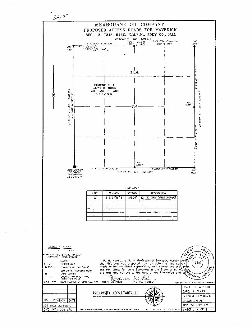
MEWBOURNE OIL COMPANY PROPOSED ACCESS ROADS FOR MAVERICK
SEC. 13, T24S, R26E, N.M.P.M., EDDY CO., N.M. (N 89'25' w - CLO - 5295.84 )
CALC. CORNER BY DOUBLE
PROPORTIONAL MEASUREMENT
N B9'32'35" W 2622.09'
(N 89'28' W - CLO
UNE TABLE FOR TWO TRACK ROAD (NEEDS UPGRADE)
LINE BEARING DISTANCE
L4 S 89'59'W E 155.68'
L5 S 86-55'49" E 141.88'
LB S 8V34'56' E 198.66'
| SCALE: ^ * = IQOtf
0 500 1000
BEARINGS: NAD 27 GRID-NM EAST DISTANCES: HORIZ. GROUND
JiCEJlD
( ) RECORD DATA + F B C " " FOUND BRASS CAP "YEAR"
— CENTERLINE PROPOSED ROAD • CALC. CORNER EXISTING TWO TRACK ROAD (NEEDS UPGRADE)
D.R.E.C.N.M. DEED RECORDS OF EDDY CO. SCALE: 1 " = 1000'
PCOSPtcRITY COnSULTAlTTS. LLC DATE: 1 1 / 1 / 1 3 PCOSPtcRITY COnSULTAlTTS. LLC SURVEYED BY: BK/ IE
NO. REVISION DATE DRAWN BY: AF
JOB NO.: LS130519 APPROVED BY: LWB
DWG. NO.: 130519RD 2 2 5 1 Doub le Creek Dr ive, Suite 6 0 2 , Round Rock, Texas 7 8 6 6 4 o 15121 9 9 2 - 2 0 8 7 1 ( 5 1 2 ) 2 5 1 - 2 5 1 8 SHEET : 1 OF 2
I, R. M. Howett, a N. M. Professional Surveyor, hereby that this plat was prepared f rom on actual ground su. made under my direct supervision, said survey and pla, the Min. Stds. for Land Surveying in the State of N. M are true and correct to the best of my knowledge and
N.M. Robert M j Howett NM PS 19680 Copyright 2013 - All Rights Reserved
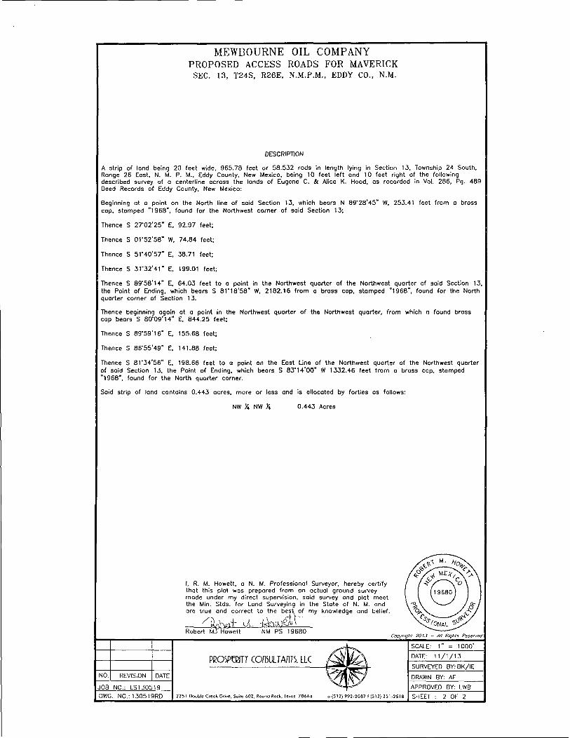
MEWBOURNE OIL COMPANY PROPOSED ACCESS ROADS FOR MAVERICK SEC. 13, T24S, R26E, N.M.P.M., EDDY CO., N.M.
DESCRIPTION
A strip of land being 20 feet wide, 965.78 feet or 58 .532 rods in length lying in Section 13. Township 24 South, Range 26 East, N. M. P. M., Eddy County. New Mexico, being 10 feet left and 10 feet r ight of the following described survey of a centerl ine across the lands of Eugene C. & Alice K. Hood, as recorded in Vol. 286 , Pg. 489 Deed Records of Eddy County. New Mexico:
Beginning at a point on the North line of said Section 13, which bears N 8 9 ' 2 8 ' 4 5 " W, 253.41 feet f rom a bross cop, s tamped "1968" , found for the Northwest corner of said Section 13;
Thence S 2 T 0 2 ' 2 5 " E, 92.97 feet ;
Thence S 0 r 5 2 ' 5 8 " W, 74 .84 feet ;
Thence S 5 T 4 0 ' 5 7 " E, 38.71 feet;
Thence S 3 1 " 3 2 ' 4 1 " E, 199.01 feet ;
Thence S 8 9 ' 5 8 ' 1 4 " E, 64.03 feet to a point in the Northwest quarter of the Northwest quarter of said Section 13, the Point of Ending, which bears S 8 V 1 8 ' 5 8 " W, 2182 .16 f r om a brass cap, s tamped "1968" , found for the North quarter corner of Section 13,
Thence beginning again at a point in the Northwest quarter of the Northwest quarter, f r om which a found brass cop bears S 8 0 ' 0 9 ' 1 4 " E, 844 .25 feet ;
Thence S 8 9 ' 5 9 ' 1 6 " E. 155.68 feet ;
Thence S 8 6 ' 5 5 ' 4 9 " E, 141.88 feet;
Thence S 8 1 ' 3 4 ' 5 6 " E. 198.66 feet to a point on the East Line of the Northwest quarter of the Northwest quarter of said Section 13, the Point of Ending, which bears S 8 3 ' 1 4 ' 0 0 " W 1332.46 feet f r om a brass cap, s tamped "1968" , found for the North quarter corner.
Said str ip of land contains 0.443 acres, more or less and is al located by for t ies as fol lows:
NW X NW X 0.443 Acres
I, R. M. Howett, a N. M. Professional Surveyor, hereby cert i fy that this plot was prepared f rom an actual ground survey made under my direct supervision, said survey and plat meet the Min. Stds. for Land Surveying in the Stote of N. M. and are true and correct to the best t of my knowledge and belief.
Robert M j Howett NM PS 19680 Copyright 20 /J - All Rights Reserved
NO. REVISION DATE
JOB NO.: LS130519
DWG. NO.: 130519RD
PBOSPQ1TT COfbULTAflTS. LLC
2251 Double Creek Drive, Suite 602. Round Rock, Texas 78664 i(512)992-2087 f(512)251-2518
SCALE: 1000'
DATE: 1 1 / 1 / 1 3
SURVEYED BY:8K/ IE
DRAWN BY: AF
APPROVED BY: LWB
SHEET : 2 OF 2
jA-2'
FBC ~I968~
5 *
MEWBOURNE OIL COMPANY PROPOSED ACCESS ROADS FOR MAVERICK
SEC. 13, T24S, R26E, N.M.P.M., EDDY CO., N.M.
S 89'28'45~ E 2848.98' - - - J_ 82
i ? ' ' J ' / s - r
(N 8925' w - CLO - 5295.84) FBC r!56.65' S 89'27'Jl" E 2648.80'
">9SB\ j (TIE) 2492.15' (TIE)
I •I I I I
T"
B.L.M.
EUGENE C. & ALICE K. HOOD
VOL. 286, PG. 489 D.R.E.C.N.M.
FBC "1968"
— •
-13-FBC
'1968'
CALC. CORNER BY DOUBLE
PROPORTIONAL MEASUREMENT
' W 2622.09
(N 89'28' W
LINE TABLE
LINE BEARING DISTANCE DESCRIPTION
LI S 8r34'56m E 198.03' EX. TWO TRACK (NEEDS UPGRADE)
1000'
1000
BEARINGS: MAD 27 GRID-NM EAST OISTANCES: HORIZ. GROUND
LEGEND
( ) RECORD DATA 4> F B C " " FOUND BRASS CAP "YEAR"
CENTERLINE PROPOSED ROAD • CALC. CORNER EXISTING TWO TRACK ROAD (NEEOS UPGRADE)
D.R.E.C.N.M. DEED RECORDS OF EDDY CO..
I, R. M. Howett, o N. M. Professionol Surveyor, hereby thot this plat was prepared f rom an actual ground su made under my direct supervision, said survey and pla the Min. Stds. for Land Surveying in the Stote of N. M are true and correct to the best of my knowledge and
3k. NM. Robert M j Howett NM PS 19680 Copyright 2013 - All Rights Reserved
NO. REVISION DATE
JOB NO.: LS130519
DWG. NO. : 130519RD
PBOSPQSn COnSULTAflTS. LLC
2251 Double Creek Drive, Suite 602, Round Rock. Texos 78664 o 15121992-2087 t(512| 251-2518
SCALE: 1 1000
DATE: 1 1 / 1 / 1 3
SURVEYED BY: BK/IE
DRAWN BY: AF
APPROVED BY: LWB
SHEET 1 OF 2
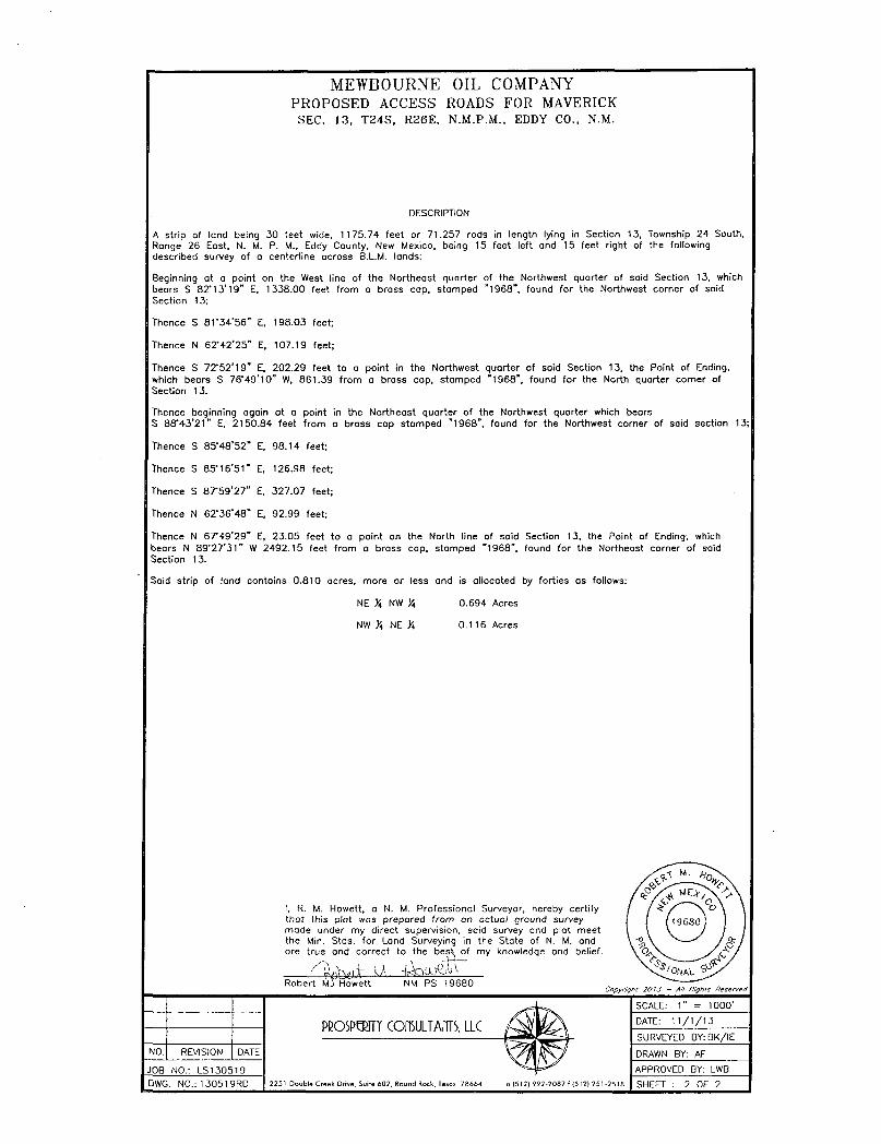
MEWBOURNE OIL COMPANY PROPOSED ACCESS ROADS FOR MAVERICK
SEC. 13, T24S, R26E, N.M.P.M., EDDY CO., N.M.
DESCRIPTION
A strip of land being 30 feet wide, 1175.74 feet or 71 .257 rods in length lying in Section 13, Township 24 South, Range 26 East, N. M. P. M., Eddy County, New Mexico, being 15 feet left and 15 feet r ight of the following described survey of a centerl ine across B.L.M. lands:
Beginning at a point on the West line of the Northeast quarter of the Northwest quarter of said Section 13, which bears S 8 2 ' 1 3 ' 1 9 " E, 1338.00 feet f r om a brass cap, s tamped "1968" , found for the Northwest corner of said Section 13;
Thence S 8 1 ' 3 4 ' 5 6 " E. 198.03 feet;
Thence N 6 2 ' 4 2 ' 2 5 " E, 107.19 feet;
Thence S 7 2 ' 5 2 ' 1 9 " E, 202.29 feet to a point in the Northwest quarter of said Section 13, the Point of Ending, which bears S 7 6 ' 4 9 ' 1 0 " W, 861.39 f r om a brass cap, s tamped "1968" , found for the North quarter corner of Section 13.
Thence beginning again at a point in the Northeast quarter of the Northwest quarter which bears
S 8 8 * 4 3 ' 2 1 " E, 2150 .84 feet f r o m a brass cop s tamped "1968" , found for the Northwest corner of said section 13;
Thence S 8 5 ' 4 8 ' 5 2 " E, 98.14 feet;
Thence S 8 5 ' 1 6 ' 5 1 " E, 126.98 feet;
Thence S 8 7 - 5 9 ' 2 7 " E, 327 .07 feet;
Thence N 6 2 ' 3 6 ' 4 8 " E, 92.99 feet;
Thence N 67°49 '29" E, 23.05 feet to a point on the North line of said Section 13, the Point of Ending, which bears N 8 9 " 2 7 ' 3 1 " W 2492 .15 feet f r o m o brass cap, s tamped "1968" , found for the Northeast corner of said Section 13.
Said str ip of land contains 0 .810 acres, more or less and is al located by fort ies as fol lows:
NE Yi, NW X 0.694 Acres
NW X NE X 0.116 Acres
I, R. M. Howett, a N. M. Professional Surveyor, hereby cert i fy thot this plot was prepared f rom an actual ground survey made under my direct supervision, soid survey and plat meet the Min. Stds. for Land Surveying in the State of N. M. and ore true and correct to the best of my knowledge and belief.
Robert M j Howett NM PS 19680 Copyright 2013 - All Rights Reserved
NO. REVISION DATE
JOB NO.: LS130519
DWG. N0. :130519RD
PPOSPPJTY (OLMTAnTS, LLC
2 2 5 1 Doub le Creek Dr ive , Suite 6 0 2 , Round Rock, lexas 7 8 6 6 4 ) | 5 1 2 ) 9 9 2 - 2 0 8 7 f ( 5 1 2 ) 2 5 1 - 2 5 1 8
SCALE: 1 " 1000
DATE: 1 1 / 1 / 1 3
SURVEYED BY: BK/ IE
DRAWN BY: AF
APPROVED BY: LWB
SHEET 2 OF 2

SECTION 12, TWP. 24 SOUTH, RGE. 26 EAST, N. M. P. M., EDDY COUNTY, NEW MEXICO
OPERATOR: Mewbourne Oil Company LEASE:. MAVERICK 13 B?CN FEDERAL COM
WELL NO.: 1H " ELEVATION: 3257'
LOCATION: 145' FSL & 1980' FWL 10" CONTOUR INTERVAL:
USGS T0P0. SOURCE MAP: Bond Draw,. NM (P.E. 1985)
- • NO. ; REVISION [ DATE,
Copyright 2013 - All Rights Reserved
JOB NO.: LS140084 DWG. NO.: 140084LVM
PROSPBITY COnSULTAfTTS. LLC
30B W. Broadway St., Hobbi, NM BB240 | firm No. TX 10193B38 NM 4655451 | (575)964-6200
SCALE: 1"=1000' 0ATE: 2/6/14 SURVEYED BY: BK/SM
DRAWN BY: AF APPROVED BY: LWB SHEET : 1 OF 1,

^3 c
VICINITY MAP NOT TO SCALE
SilSliliiiB
- j -JF ' ^ .jMSL ays
. * '!• • *. ' I !-
• 1*• -*** fef J | MAVERICK 13 B2CN FEDERAL COM #1H B \—» • ' >'v ' w , ..v'
^*'-*s . . A t l „ — — * . •"
SECTION 12, TWP. 24 SOUTH, RGE 26 EAST, N. M. P. M., EDDY COUNTY, NEW MEXICO
OPERATOR: Mewbourne Oil Company LEASE: MAVERICK 13 B2CN FEDERAL COM '
LOCATION: 145' .FSL ,& 1980'
ELEVATION: 3257' FWL.
WELL NO. 1H
NOI s REVISION DATE
JOB, NO.: LS14Q084 DWG. NO.: 140084VM
Copyright 2013 - All Rights Reserved
PBOSIWT COITSLLTAfTTS. LLC
308 Vf. Broadway St., Hobbi, NM 86240 | Hrm No. TX 10193B3B NM 4685451_ | (575) °64-B200
SCALE: N.T.S. DATE: 2/6/14
SURVEYED "BY: BK/SM
DRAWN BY: AF. APPROVED BY: LWB SHEET : 1 OF 1


Exhibit 4
C
~ l > r n i t n < i rvVr-l l 'Sl . i rO
A f i a n i i o n « * c f L o r . u l o n I f *e r m i (
C J S W e l l
O i l V v - l l
O H a n d C . i i W e i l
O l h < T < O h \ < > T v . i t I o n . C I O
( n J r r t J o n W r i t
" S u i p e n r J c d
5 " i i r | ' i > i l « . , \ v . . I I
n.jgfj. <i cn v. i S ' l u q q c d O i l a n d
O f y H o l r l M o I t i o v i v ,
D r y M o l e n / C ? < ' . f ' D i v
I > i y H u l l . v / ( / I ' | I Q W
I > r y H o l e - w / O I I J " i f G. i •. = S h o w
Surface Location Maverick 13 B2CN Fed Com #1H
Sec 12T24SR26E

Exhibit "4A"
—^7:p " ! "ng " (NVe i i Stale ?§§
i Abandoned l joc.Hon SB ( r c r m i o : " j§5
.i3g.lj.Well*..- - •]
* Oil'anirliG.is W F I I
^g j ^ thc r /CObaerv i l l on . r tOM
.fesinjeciio'taweii > SB ^ Suspendr-tJ
Plugqed Ca» Well 1 >
j / . Ptuqncd Oi l J>i'J C n V
A. 'Ory 'Mote lNo Shows) '; -VfS1
j i ' . jOry.Hole w/Gas Show-«£f.
v^ iDry .Ho lp w'/OII and Ca ig ;
Bottom Hole Location Maverick 13 B2CN Fed Com #1H
Sec 12T24SR26E

Drilling Program Mewbourne Oil Company
Maverick 13 B2CN Fed Com #1H 145' FSL & 1980' FWL
Sec 12,T24S,R26E Eddy County, New Mexico
1. The estimated tops of geological markers are as follows:
Rustler 105' Top Salt 540' Base Salt 1870' *Yates NA Seven Rivers NA *Queen NA Grayburg NA San Andres NA *Lamar/Delaware 1990' *Bone Springs 5400' * 1 s t Bone Springs 6390' *2 n d Bone Springs 6930' *Wolfcamp Will not penetrate
2. Estimated depths of anticipated fresh water, oil, or gas:
Water Fresh water is anticipated @ 60' and will be protected by setting surface casing at 400' and cementing to surface.
Hydrocarbons Oil and gas are anticipated in the above (*) formations. These zones will be protected by casing as necessary.
3. Pressure control equipment:
A2000# WP annular will be installed after running 13 3/8" casing. A 3000# WP double ram BOP and 3000# WP Annular will be installed after running 9 %" & 7" casing. Pressure tests will be conducted prior to drilling out under all casing strings. BOP controls will be installed prior to drilling under surface casing and will remain in use until completion of drilling operations. BOPs will be inspected and operated as recommended in Onshore Order #2. A Kelly cock and a sub equipped with a full opening valve sized to fit the drill pipe and collars will be available on the rig floor in the open position when the Kelly is not in use. Will test the 13 3/8" annular to 1500# and the 9 %" & 7" BOPE to 3000# and annular to 1500# with a third party testing company before drilling below each shoe, but will test again, if needed, in 30 days from the 1 s t test as per BLM Onshore Oil and Gas Order #2.
4. MOC proposes to drill a vertical wellbore to 6580' & kick off to horizontal @ 7057' TVD. The well will be drilled to 11971' MD (7087' TVD). See attached directional plan.
5. Proposed casing and cementing program:
A. Casing Program: Hole Size Casinq 17 1/2M 13 3/8" (new)
Wt/Ft. 48#
Grade H40
Depth 0' - 400'
Jt Type ST&C
12 %" 9 5/8" (new) 36# J55 0' - 1935' MD LT&C
8 V*" 8 %" 6 1/8"
7" (new) 7" (new) 4 1/2" (new)
26# 26# 13.5#
P110 P110 P110
0'-6580' MD 6580'-7326' MD 7126'-11971' MD
LT&C BT&C LT&C

Drilling Program Mewbourne Oil Company Maverick 13 B2CN Fed Com #1H Page 2
Minimum casing design factors: Collapse 1.125, Burst 1.0, Tensile strength 1.8. *Subject to availability of casing.
B Cementing Program:
i. Surface Casing: 300 sks Class C cement containing 1% CaCI2. Yield at 1.33 cuft/sk. Mix water @ 6.34 gal/sk. Cmt circulated to surface w/100% excess.
ii Intermediate Casing: 260 sacks Class C light cement with salt & LCM. Yield at 2.15 cuft/sk. Mix water® 11.29 gal/sk. 200 sacks Class C cement. Yield at 1.33 cuft/sk. Mix water @ 6.34 gal/sk. Cmt circulated to surface w/25% excess.
iii. Production Casing: 400 sacks *Lite "C" (35:65:4) cement w/salt and fluid loss additives. Yield at 2.12 cuft/sk. Mix water @ 11.32 gal/sk. 350 sacks Class "H" cement w/ salt & FLA additives. Yield at 1.18 cuft/sk. Mix water @ 5.22 gal/sk. Calculated to tie back inside 9 5/8" csg 200' w/25% excess.
iv. Production Liner: This will be a Packer/Port completion from TD up inside 7" casing with packer type liner hanger.
'Referring to above blends of light cement: (65% fly ash : 35% cement: 4% bentonite of the total of first two numbers). Generic names of additives are used since the availability of specific company and products are unknown at this time.
6. Mud Program:
Interval Type System Weight Viscosity Fluid Loss 0'-400' FW spud mud 8.6-9.0 32-34 NA 400'- 1935' Brine water 10.0-10.2 28-30 NA 1935'-6580'(KOP) FW 8.5-8.7 28-30 NA 6580'-TD FWw/Polymer 8.5-8.7 32-35 15 "Visual mud monitoring system shall be in place to detect volume changes indicating loss or gain of circulation fluid volume. Sufficient mud materials will be kept on location at all times to combat abnormal conditions.
7. Evaluation Program:
Samples: 10'samples from KOP to TD
Logging: GR, CN & Gyro 100' above KOP (6480') to surface. GR from 6480' to TD.
8. Downhole Conditions
Zones of abnormal pressure: None anticipated Zones of lost circulation: Anticipated in surface and intermediate holes ^ ) /d Maximum bottom hole temperature: 120 degree F
MOC does not anticipate H2S, however H2S contingency plan is attached Maximum bottom hole pressure: 8.3 lbs/gal gradient or less (.43668 x 7087-3095 psi)
9. Anticipated Starting Date:
Mewbourne Oil Company intends to drill this well as soon as possible after receiving approval with approximately 40 days involved in drilling operations and an additional 20 days involved in completion operations on the project.

Mewbourne Oil Company. Eddy County, New Mexico Section 12/13-24S-26E Maverick 13 B2CN Fed #1H Maverick 13 B2CN Fed Com #1H
Original Hole
Plan: Plan#1
Standard Planning Report 12 March, 2014

/
Di i td i ) • f
Company
PlOj l 'Ct
Site:
Well : WLllbnrc DP lyn
! Project
Map System: Geo Datum: Map Zone:
Stryker Directional Planning Report
; EDM5000.1 .SingleUser.Db lOlewbqurne Oil Company.
'Eddy .County; New Mexico
|Section.1 :2/i3r24S-26E Maverickl 3 ;B2CN
| M a w r i c k ^ a B ^ N j F e a . Com#1H'. ^rigjnal-Hple^r^ - . PiareM^.if"";!'U •
Local Co-ordinate Reference: TVD Reforenrp
MD Rt f iT i iii,c
North Riifori-nrn
Survey Calculation Method:
f Well Maverick 1,3 B2CN Fed Com #1H j GL 3257 + 20 @ 3277l0usft (Original Well I Elev) ' '
GL 3257 + 20 @'3277.0usft (Original Well Elev) Grid •
Minimum Curvature '. •" • ,
EddyjG^uhtyfNewMexico"
US State Plane 1927 (Exact solution) NAD 1927 (NADCON CONUS) New Mexico East 3001
System Datum: Mean Sea Level
Site Sectiofn2/13-24S-26E . Maverick 13 B2CN Fed #1H 13 Site Posit ion: From: . Map
Position Uncertainty:
Northing:
Easting:
0.0 usft Slot Radius:
445,533.00 usft Latitude: 526,323.40 usft Longitude:
13-3/16" Grid Convergence:
32° 13' 29.491 N 104° 14' 53.554 W
0.05 °
Well Maverick 13-B2CN Fed CorrV#1 H"
Well Position +N/-S
+E/-W
Position Uncertainty
0.0 usft Northing:
0.0 usft Easting:
0.0 usft Wellhead Elevation:
445,533.00 usft
526,323.40 usft
Latitude:
Longitude:
Ground Level:
32° 13'29.491 N
104° 14' 53.554 W
3,257.0 usft
Wellbore
' Maqnetics
Origihal'Hblej v... r. "- '
Model Niinir
IGRf 2010
Sample Date
3/12/2014
Declination P i | A n g l o
(") 7 56 CO 00
Field Strength (nT)
48"270"
DI-SKJII
Audit Notes:
Version:
Vf r t i r . i l Sr-rtion
, Plan#1
Phase:
Depth From (TVD)
PROTOTYPE
fN/-S
Tie On Depth:
+ E ' W
0.0
Direction (usft) (usft) B j ^ ^ ^ H U : ^ ^ ^ ^
0 0~ 0 () 0 1 7941
Pl.in Si-c Hons
Measured Vertical Cw.j l iy nu.ui Turn Di-pth lm.hn.itmn A/ imuth Depth - N -S +E/-W RdtO Rate Rate r ro (usft) (usft) (usft) Hi ' f t ) I 100l l i t t l 1 I00us.lt) i °/1 OOusft)
0.0 0.00 0.00 0.0 0.0 0.0 0.00 0.00 0.00 0.00 6,579.5 0.00 0.00 6,579.5 0.0 0.0 0.00 0.00 0.00 0.00 7,326.4 89.63 179.41 7,057.0 -474.4 4.9 12.00 12.00 24.02 179.41
11,970.7 89.63 179.41 7,087.0 -5,118.3 52.5 0.00 0.00 0.00 0.00
T, i r ' ] i t
3/12&014 9:59:19AM Page 2 COMPASS 5000.1 Build 65

Database Company
Project:
Site.
l/Voll Wellbore: Design-
Pl.inn- d Sur.i ' /
Stryker Directional Planning Report
' EDM 500oT SingfeTTser Db , Mewbournepil:Cbmpany.
' Eddy^Courity^New Mexico
! Section 12/13-24S-26E • Maverick 13 B2CN Fed *1H
/Maverick 13 B2CN Fed Com #1H ^Original Hole - - •
' Local Co-ordinate Reference: TVD Reference:
MD Refcrenro
North Roferonro
Survey Calculation Method:
Well Maverick 13.B2CN Fed Com #1H I GL 3257 + 20 @ 3277.0usft (Original ;Well Elev) GL 3257 + 20 @ 3277.0usft (Original Well Elev) Grid
Minimum Curvature
— * -
leasured Ver t ic i l Vortit a I Dogleg Build T u i l l
Depth Inclination Azimuth Depth t-N S +E.-W SIM t inn Rate R.ite Rate (usft) (Usf t ) (usft) (usft) ( l i s f t ) ( /1G0u&ftl !°/100usft) (71 OOusft)
0.0 0.00 0.00 0.0 0.0 0.0 0.0 0.00 0.00 0.00 100.0 0.00 0.00 100.0 0.0 0.0 0.0 0.00 0.00 0.00 200.0 0.00 0.00 200.0 0.0 0.0 0.0 0.00 0.00 0.00 300.0 0.00 0.00 300.0 0.0 0.0 0.0 0.00 0.00 0.00 400.0 0.00 0.00 400.0 0.0 0.0 0.0 0.00 0.00 0.00
500.0 0.00 0.00 500.0 0.0 0.0 0.0 0.00 0.00 0.00 600.0 0.00 0.00 600.0 0.0 0.0 0.0 0.00 0.00 0.00 700.0 0.00 0.00 700.0 0.0 0.0 0.0 0.00 0.00 0.00 800.0 0.00 0.00 800.0 0.0 0.0 0.0 0.00 0.00 0.00 900.0 0.00 0.00 900.0 0.0 0.0 0.0 0.00 0.00 0.00
1,000.0 0.00 0.00 1,000.0 0.0 0.0 0.0 0.00 0.00 0.00 1,100.0 0.00 0.00 1,100.0 0.0 0.0 0.0 0.00 0.00 0:00 1,200.0 0.00 0.00 1,200.0 0.0 0.0 0.0 0.00 0.00 0.00 1,300.0 0.00 0.00 1,300.0 0.0 0.0 0.0 0.00 0.00 0.00 1,400.0 0.00 0.00 1,400.0 0.0 0.0 0.0 0.00 0.00 0.00
1,500.0 0.00 0.00 1,500.0 0.0 0.0 0.0 0.00 0.00 0.00 1,600.0 0.00 0.00 1,600.0 0.0 0.0 0.0 0.00 0.00 0.00 1,700.0 0.00 0.00 1,700.0 0.0 0.0 0.0 0.00 0.00 0.00 1,800.0 0.00 0.00 1,800.0 0.0 0.0 0.0 0.00 0.00 0.00 1,900.0 0.00 0.00 1,900.0 0.0 0.0 0.0 0.00 0.00 0.00
2,000.0 0.00 0.00 2,000.0 0.0 0.0 0.0 0.00 0.00 0.00 2,100.0 0.00 0.00 2,100.0 0.0 0.0 0.0 0.00 0.00 0.00 2,200.0 0.00 0.00 2,200.0 0.0 0.0 0.0 0.00 0.00 0.00 2,300.0 0.00 0.00 2,300.0 0.0 0.0 0.0 0.00 0.00 0.00 2,400.0 0.00 0.00 2,400.0 0.0 0.0 0.0 0.00 0.00 0.00
2,500.0 0.00 0.00 2,500.0 0.0 0.0 0.0 0.00 0.00 0.00 2,600.0 0.00 0.00 2,600.0 0.0 0.0 0.0 0.00 0.00 0.00 2,700.0 0.00 0.00 2,700.0 0.0 0.0 0.0 0.00 0.00 0.00 2,800.0 0.00 0.00 2,800.0 0.0 0.0 0.0 0.00 0.00 0.00 2,900.0 0.00 0.00 2,900.0 0.0 0.0 0.0 0.00 0.00 0.00
3,000.0 0.00 0.00 3,000.0 0.0 0.0 0.0 0.00 0.00 0.00 3,100.0 0.00 0.00 3,100.0 0.0 0.0 0.0 0.00 0.00 0.00 3,200.0 0.00 0.00 3,200.0 0.0 0.0 0.0 0.00 0.00 0.00 3,300.0 0.00 0.00 3,300.0 0.0 0.0 0.0 0.00 0.00 0.00 3,400.0 0.00 0.00 3,400.0 0.0 0.0 0.0 0.00 0.00 0.00
3,500.0 0.00 0.00 3,500.0 0.0 0.0 0.0 0.00 0.00 0.00 3,600.0 0.00 0.00 3,600.0 0.0 0.0 0.0 0.00 0.00 0.00 3,700.0 0.00 0.00 3,700.0 0.0 0.0 0.0 0.00 0.00 0.00 3,800.0 0.00 0.00 3,800.0 0.0 0.0 0.0 0.00 0.00 0.00 3,900.0 0.00 0.00 3,900.0 0.0 0.0 0.0 0.00 0.00 0.00
4,000.0 0.00 0.00 4,000.0 0.0 0.0 0.0 0.00 0.00 0.00 4,100.0 0.00 0.00 4,100.0 0.0 0.0 0.0 0.00 0.00 0.00 4,200.0 0.00 0.00 4,200.0 0.0 0.0 0.0 0.00 0.00 0.00 4,300.0 0.00 0.00 4,300.0 0.0 0.0 0.0 0.00 0.00 0.00 4,400.0 0.00 0.00 4,400.0 0.0 0.0 0.0 0.00 0.00 0.00
4,500.0 0.00 0.00 4,500.0 0.0 0.0 0.0 0.00 0.00 0.00 4,600.0 0.00 0.00 4,600.0 0.0 0.0 0.0 0.00 0.00 0.00 4,700.0 0.00 0.00 4,700.0 0.0 0.0 0.0 0.00 0.00 0.00 4,800.0 0.00 0.00 4,800.0 0.0 0.0 0.0 0.00 0.00 0.00 4,900.0 0.00 0.00 4,900.0 0.0 0.0 0.0 0.00 0.00 0.00
5,000.0 0.00 0.00 5,000.0 0.0 0.0 0.0 0.00 0.00 0.00
3/12/2014 9:59:19AM Page 3 COMPASS 5000.1 Build 65

Stryker Directional Planning Report
Database 'Company:
Pr i i j t v t
'Site:
Well. Welltic rp Di"".iqn
i Planned Siirvoy
•EDM.5000.-1 Single User-Db Wlewbourne.Oil Company .
Eddy County,* New-Mexico
Section:/!2/13-24S-26E Maverick 13 B2CN iFed#1H ' MaVeqck;i3iB2CNFed>Com:#1H
jOriginalM-lole^. J' '* ' , Plarf#1" - h>
Local Co-ordinate Reference: TVD Reference:
MD Rcf( r.-nre
North Reference
Sur.py Calculation Mettled
Well Maverick 13 B2CN Fed Com #1H GL 3257 + 20 @ 3277'!ous'n (Original Well Elev)- ' • ' . GL 3257 + 20 @ 3277:0usft (OriginalWell Eiev) : - . -Grid ' >, . - *•• . .
M
Mi .isurod Vertical Vertical Dorili'i) Build Turn LVpth InUuutioii Azimuth Depth tN> S +E/-W Section Rate Rato Rate (usft) o (usft) I libit) (usft) (usft) i 1 OOusft I 1D0.i-j.lt) (7l00usft)
0.00 0.00 5,100.0 0.0 o.„ 0.00 0.00 0.00 5^00.0 0.00 0.00 5,200.0 0.0 0.0 0.0 0.00 0.00 0.00 5,300.0 0.00 0.00 5,300.0 0.0 0.0 0.0 0.00 0.00 0.00 5,400.0 0.00 0.00 5,400.0 0.0 0.0 0.0 0.00 0.00 0.00
5,500.0 0.00 0.00 5,500.0 0.0 0.0 0.0 0.00 0.00 0.00 5,600.0 0.00 0.00 5,600.0 0.0 0.0 0.0 0.00 0.00 0.00 5,700.0 0.00 0.00 5,700.0 0.0 0.0 0.0 0.00 0.00 0.00 5,800.0 0.00 0.00 5,800.0 0.0 0.0 0.0 0.00 0.00 0.00 5,900.0 0.00 0.00 5,900.0 0.0 0.0 0.0 0.00 0.00 0.00
6,000.0 0.00 0.00 6,000.0 0.0 0.0 0.0 0.00 0.00 0.00 6,100.0 0.00 0.00 6,100.0 0.0 0.0 0.0 0.00 0.00 0.00 6,200.0 0.00 0.00 6,200.0 0.0 0.0 0.0 0.00 0.00 0.00 6,300.0 0.00 0.00 6,300.0 0.0 0.0 0.0 0.00 0.00 0.00 6,400.0 0.00 0.00 6,400.0 0.0 0.0 0.0 0.00 0.00 0.00
6,500.0 0.00 0.00 6,500.0 0.0 0.0 0.0 0.00 0.00 0.00 6,579.5 0.00 0.00 6,579.5 0.0 0.0 0.0 0.00 0.00 0.00
46579;5-;r»ll2irsU 6,600.0
2.46 179.41 6,600.0 -0.4 0.0 0.4 12.00 12.00 ' 0.00 6,625.0 5.46 179.41 6,624.9 -2.2 0.0 2.2 12.00 12.00 0.00 6,650.0 8.46 179.41 6,649.7 -5.2 0.1 5.2 12.00 12.00 0.00
6,675.0 11.46 179.41 6,674.4 -9.5 0.1 9.5 12.00 12.00 0.00 6,700.0 14.46 179.41 6,698.7 -15.1 0.2 15.1 12.00 12.00 0.00 6,725.0 17.46 179.41 6,722.8 -22.0 0.2 22.0 12.00 12.00 0.00 6,750.0 20.46 179.41 6,746.4 -30.1 0.3 30.1 12.00 12.00 0.00 6,775.0 23.46 179.41 6,769.6 -39.5 0.4 39.5 12.00 12.00 0.00
6,800.0 26.46 179.41 6,792.2 -50.0 0.5 50.0 12.00 12.00 0.00 6,825.0 29.46 179.41 6,814.3 -61.7 0.6 61.7 12.00 12.00 0.00 6,850.0 32.46 179.41 6,835.8 -74.6 0.8 74.6 12.00 12.00 0.00 6,875.0 35.46 179.41 6,856.5 -88.6 0.9 88.6 12.00 12.00 0.00 6,900.0 38.46 179.41 6,876.5 -103.6 1.1 103.6 12.00 12.00 0.00
6,925.0 41.46 179.41 6,895.6 -119.6 1.2 119.6 12.00 12.00 0.00 6,950.0 44.46 179.41 6,913.9 -136.7 1.4 136.7 12.00 12.00 0.00 6,975.0 47.46 179.41 6,931.3 -154.6 1.6 154.6 12.00 12.00 0.00 7,000.0 50.46 179.41 6,947.7 -173.5 1.8 173.5 12.00 12.00 0.00 7,025.0 53.46 179.41 6,963.1 -193.2 2.0 193.2 12.00 12.00 0.00
7,050.0 56.46 179.41 6,977.5 -213.6 2.2 213.7 12.00 12.00 0.00 7,075.0 59.46 179.41 6,990.7 -234.8 2.4 234.8 12.00 12.00 0.00 7,100.0 62.46 179.41 7,002.9 -256.7 2.6 256.7 12.00 12.00 0.00 7,125.0 65.46 179.41 7,013.8 -279.1 2.9 279.2 12.00 12.00 0.00 7,150.0 68.46 179.41 7,023.6 -302.1 3.1 302.2 12.00 12.00 0.00
7,175.0 71.46 179.41 7,032.2 -325.6 3.3 325.6 12.00 12.00 0.00 7,200.0 74.46 179.41 7,039.5 -349.5 3.6 349.5 12.00 12.00 0.00 7,225.0 77.46 179.41 7,045.6 -373.8 3.8 373.8 12.00 12.00 0.00 7,250.0 80.46 179.41 7,050.4 -398.3 4.1 398.3 12.00 12.00 0.00 7,275.0 83.46 179.41 7,053.9 -423.1 4.3 423.1 12.00 12.00 0.00
7,300.0 86.46 179.41 7,056.1 -448.0 4.6 448.0 12.00 12.00 0.00 7,326.4 89.63 179.41 7,057.0 -474.3 4.9 474.4 12.00 12.00 0.00
7326i4''Mb LP 7,400.0 89.63 179.41 7,057.4 -547.9 5.6 548.0 0.00 0.00 0.00 7,500.0 89.63 179.41 7,058.1 -647.9 6.6 648.0 0.00 0.00 0.00 7,600.0 89.63 179.41 7,058.7 -747.9 7.7 748.0 0.00 0.00 0.00
3/12/2014 9:59:19AM Page 4 COMPASS 5000.1 Build 65

Stryker Directional Planning Report
jDatabase: EDM 5000.1.Single User Db Company: Mewbourne Oil Company .
Project Eddy County, New Mexico
ISite: Section 12/13-24S-26E Maverick 13 B2CN Fed#1H , .
Well: Mavefick 13 B2CN Fed Com #1H Wellbore: 'Original Hole Design: Plan#1
Local Co-ordinate Reference: Well M.ivenck 13 B2CN Fed Com #1H
TVD Reference:
MD Reference:
North Reference:
GL 3257 + 20 @ 3277:0usft (Original Well Elev) ' -GL 3257 i- 20 @ 3277.0usft (Original Well Elevj Grid . '
Survey Calculation Method: Minimum Curvature
Planned Survey
i i i l l r e d Vertical Ver t ic i l Dogl rg Build Turn Dr pth Inclination Ar imuth Depth + N S +E/-W Section Rate Rate Rate (U'.ft) n BlHi (usft) l u . l t ) (usft) (usft) (7100u- ft) ( /1 OOusft) (7100usft)
7,700.0 89.63 179.41 7,059.4 -847.9 8.7 848.0 0.00 0.00 0.00 7,800.0 89.63 179.41 7,060.0 -947.9 9.7 948:0 0.00 0.00 0.00 7,900.0 89.63 179.41 7,060.7 -1,047.9 10.7 1,048.0 0.00 0.00 0.00 8,000.0 89.63 179.41 7,061.3 -1,147.9 11.8 1,148.0 0.00 0.00 0.00 8,100.0 89.63 179.41 7,062.0 -1,247.9 12.8 1,247.9 0.00 0.00 0.00
8,200.0 89.63 179.41 7,062.6 -1,347.9 13.8 1,347.9 0.00 0.00 0.00 8,300.0 89.63 179.41 7,063.3 -1,447.9 14.8 1,447.9 0.00 0.00 0.00 8,400.0 89.63 179.41 7,063.9 -1,547.9 15.9 1,547.9 0.00 0.00 0.00 8,500.0 89.63 179.41 7,064.5 -1,647.9 16.9 1,647.9 0.00 0.00 0.00 8,600.0 89.63 179.41 7,065.2 -1,747.8 17.9 1,747.9 0.00 0.00 0.00
8,700.0 89.63 179.41 7,065.8 -1,847.8 18.9 1,847.9 0.00 0.00 0.00 8,800.0 89.63 179.41 7,066.5 -1,947.8 20.0 1,947.9 0.00 0.00 0.00 8,900.0 89.63 179.41 7,067.1 -2,047.8 21.0 2,047.9 0.00 0.00 0.00 9,000.0 89.63 179.41 7,067.8 -2,147.8 22.0 2,147.9 0.00 0.00 0.00 9,100.0 89.63 179.41 7,068.4 -2,247.8 23.0 2,247.9 0.00 0.00 0.00
9,200.0 89.63 179.41 7,069.1 -2,347.8 24.1 2,347.9 0.00 0.00 0.00 9,300.0 89.63 179.41 7,069.7 -2,447.8 25.1 2,447.9 0.00 0.00 0.00 9,400.0 89.63 179.41 7,070.4 -2,547.8 26.1 2,547.9 0.00 0.00 0.00 9,500.0 89.63 179.41 7,071.0 -2,647.8 27.1 2,647.9 0.00 0.00 0.00 9,600.0 89.63 179.41 7,071.7 -2,747.8 28.2 2,747.9 0.00 0.00 0.00
9,700.0 89.63 179.41 7,072.3 -2,847.8 29.2 2,847.9 0.00 0.00 0.00 9,800.0 89.63 179.41 7,073.0 -2,947.8 30.2 2,947.9 0.00 0.00 0.00 9,900.0 89.63 179.41 7,073.6 -3,047.8 31.2 3,047.9 0.00 0.00 0.00
10,000.0 89.63 179.41 7,074.3 -3,147.7 32.3 3,147.9 0.00 0.00 0.00 10,100.0 89.63 179.41 7,074.9 -3,247.7 33.3 3,247.9 0.00 0.00 0.00
10,200.0 89.63 179.41 7,075.5 -3,347.7 34.3 3,347.9 0.00 0.00 0.00 10,300.0 89.63 179.41 7,076.2 -3,447.7 35.3 3,447.9 0.00 0.00 0.00 10,400.0 89.63 179.41 7,076.8 -3,547.7 36.4 3,547.9 0.00 0.00 0.00 10,500.0 89.63 179.41 7,077.5 -3,647.7 37.4 3,647.9 0.00 0.00 0.00 10,600.0 89.63 179.41 7,078.1 -3,747.7 38.4 3,747.9 0.00 0.00 0.00
10,700.0 89.63 179.41 7,078.8 -3,847.7 39.4 3,847.9 0.00 0.00 0.00 10,800.0 89.63 179.41 7,079.4 -3,947.7 40.5 3,947.9 0.00 0.00 0.00 10,900.0 89.63 179.41 7,080.1 -4,047.7 41.5 4,047.9 0.00 0.00 0.00 11,000.0 89.63 179.41 7,080.7 -4,147.7 42.5 4,147.9 0.00 0.00 0.00 11,100.0 89.63 179.41 7,081.4 -4,247.7 43.5 4,247.9 0.00 0.00 0.00
11,200.0 89.63 179.41 7,082.0 -4,347.7 44.6 4,347.9 0.00 0.00 0.00 11,300.0 89.63 179.41 7,082.7 -4,447.6 45.6 4,447.9 0.00 0.00 0.00 11,400.0 89.63 179.41 7,083.3 -4,547.6 46.6 4,547.9 0.00 0.00 0.00 11,500.0 89.63 179.41 7,084.0 -4,647.6 47.6 4,647.9 0.00 0.00 0.00 11,600.0 89.63 179.41 7,084.6 -4,747.6 48.7 4,747.9 0.00 0.00 0.00
11,700.0 89.63 179.41 7,085.2 -4,847.6 49.7 4,847.9 0.00 0.00 0.00 11,800.0 89.63 179.41 7,085.9 -4,947.6 50.7 4,947.9 0.00 0.00 0.00 11,900.0 89.63 179.41 7,086.5 -5,047.6 51.7 5,047.9 0.00 0.00 0.00 11,970.7 89.63 179.41 7,087.0 -5,118.3 52.5 5,118.6 0.00 0.00 0.00
11970 7" MD PBHL
3/12/2014 9:59:19AM Page 5 COMPASS 5000.1 Build 65

Databasu Company.
Project
Site:
Well: Vvr llboru DPSKJII"
Design Targets
Stryker Directional Planning Report
'EDM 5000.1 Single User Db • i Mewbourne Oil Company •
Eddy County, New Mexico . . ,
:Section12/13-24S-26E: Maverick 13 B2CN Fed#.1H' ' ' ..
!Maver ickJ3B2CNFedCom#1H
lipriginal-Hole' . . '•
rPlan#A.>:'"> • •
[ Local Co-ordinate Reference:
i TVD Reference:
[MD Reference
mm
5S { North Reference:
' Survey Calculation Method:
Well Maverick 13 B2CN Fed Com #1H GL 3257 + 20 @ 3277.0usft (Original Well Elev)
I GL 3257 + 20 @ 3277.0usft (Original Well ' Elev)
Grid x : '..
Minimum Curvature
la i r j i - t Nairn. - hit/miss target Dip Angle Dip Dir. - Shape (")• (•) -
TVD (usft)
+N/-S (usft)
+E/-W (usft)
Northing (usft) '
Easting (usft) Latitude Longitude
LP Maverick 13 B2CN 0.00 0.00 7,057.0 -475.0 5.9 445,058.04 - plan misses target center by 1 Ousft at 7327.0usft MD (7057.0 TVD, -475.0 N, 4.9 E) - Point
PBHL Maverick 13 B2 0.00 - plan hits target center - Point
0.00 7,087.0 -5,118.3 52.5 440,414.68
526,329.29 32° 13' 24.791 N 104° 14' 53.489 W
526,375.87 32" 12' 38.838 N 104° 14'52.990 W
. Plan An lot. i t ions
Vpa-.iirpd Depth (usft)
Ygi t«.- I Depth (Ssft) . __
1 C u O i d i i i . i t f " . • N S + & W (usft) (usft) Comment
i lpl l i i l i l i t
111 6,579.5 7,326.4
11,970.7
6,579.5 7,057.0 7,087.0
0.0 -474.3
-5,118.3
0.0 6579.5' MD KOP 4.9 7326.4' MD LP
52.5 11970.7'MD PBHL
3/12&014 9:59:19AM Page 6 COMPASS 5000.1 Build 65

z O I R B C T I O N A L
Mewbourne Oil Company. Eddy County, New Mexico Section 12/13-24S-26E Maverick 13 B2CN Fed #1H Maverick 13 B2CN Fed Com #1H
Original Hole
warn wMBUSm
I -si*!
Plan: Plan#1 PlillliS
Klin
Standard Planning Report - Geographic 12 March, 2014 Hl l l l
MSB

Database. Comp.iny
Project
Sito
Well-Wellbore Desiqn
Project
Map System: Geo Datum: Map Zone:
Stryker Directional Planning Report - Geographic
JJL
;EDM'5000.tSingle User Db Mewbourne Oil Company.
. "' :=; ••/r • ' lEddy County, New Mexico
• t f f " ^ ' • > -
Section ,12/13-24S-26E Maverick 13 B2CN North Reference
!M^r i ^3 ' :B2CN: 'Fed ' -Com * l ' R " - - Survey Calculation Method: ipriginahHpley.:'"-:.. , ' v -?w -:
' P lan#f . , j
Local Co-ordinate Reference: I Well Maverick 13 B2CN Fed Com #1H , TVD Reference: GL 3257 + 20 @ 3277.0usfl(Original Well
Elev) . y - ,.; MD Reference: * GL 3257 + 20 ';3'277.'0usft (Original Well
Elev) . .;• ; ^ . ; " : V- '> . ~': • " ' Grid' ~ - X \ : ' . •' ' • ;'- .
US State Plane 1927 (Exact solution) NAD 1927 (NADCON CONUS) New Mexico East 3001
System Datum:
Minimum'Curvature
Mean Sea Level
Site
Site Posit ion:
From: Map
Position Uncertainty:
Northing:
Easting:
0.0 usft Slot Radius:
445,533.00 usft Latitude: 526,323.40 usft Longitude:
13-3/16 " Grid Convergence:
32° 13' 29.491 N 104° 14' 53.554 W
0.05°
Well
Well Position
l jMaver ick:13]B2CNfej jC ••
+N/-S 0.0 usft Northing:
+E/-W
Position Uncertainty
0.0 usft Easting:
0.0 usft Wellhead Elevation:
445,533.00 usft
526,323.40 usft
Latitude:
Longitude:
Ground Level:
32° 13' 29.491 N
104° 14' 53.554 W
3,257.0 usft
Wellbore
Mjgnet ies
'nqinal Hole-
Yodel N.inio
IGRF2010
Sample Ddto
3/12/2014
Declination Dip Anglo ( )
7.56 60.00
Field Strength (nT) •_
48"270
Design Plan#1
Audit Notes:
Version:
Vertical Section:
Phase:
Depth Fiom (TVD) (usft)
0 0
PROTOTYPE
" " + N / - S ( i i . f t )
OLO
Tie On Depth:
+E W (usft)
0 0
0.0
Direction
179 41
Pl.in St i t i nns
Measured Depth (usft)
In. hnation A7iinuth VurtK.i l
Depth (u .ft)
+N/-S (usft)
+Ei W (ii f t l
Dnqlcg Rate
I 10Ou .ft)
Bui ld Rate
l ,100uslt)
Turn Rate
l 100u .ft) TFO
( ) l . i rqi t
0.0 0.00 0.00 0.0 0.0 0.0 0.00 0.00 0.00 0.00 6,579.5 0.00 0.00 6,579.5 0.0 0.0 0.00 0.00 0.00 0.00 7,326.4 89.63 179.41 7,057.0 -474.4 4.9 12.00 12.00 24.02 179.41
11,970.7 89.63 179.41 7,087.0 -5,118.3 52.5 0.00 0.00 0.00 0.00
3/12/2014 10:00:19AM Page 2 COMPASS 5000.1 Build 65

Stryker Directional Planning Report - Geographic
Database: *, " |? Company
Project
Srtej^^te?#||
Woll. Iwullboro [Design
Planned Survey
' EDM.5000.1 Single User Db ; Mewbourne. Oil Company . •
Eddy County; NewMexico
Local Co-ordinate Reference: TVD Rulerence
MD Rofercnro
Section 12/13-24S-26E Maverick .13 B2CN i North Reference-Fed#iH ' : : - ' . ' " , / Maverick 13 B2CN Fed Corh#1H" ' Origina'l;Hoie, ' . „.•>.? ' • Pianfe '
Survey Calculation Method:
Well Maverick 13 B2CN Fed Com #1H, GL 3257 + 20 @ 3277:0usft (Original Well Elev) GL 3257 + 20 @ 3277.0usft (Original Well | Elev) • 1 Grid • . • :. §
Minimum Curvature .. , " ' ' . • s
Measu-r-d Vorticjl Map M.ip Depth .Inclination Azimuth Depth +N/-S +E/-W Northing Easting (usft) I usft) (usft) (usft) (usft) (usft) L atitudu Lonnitudo
0.0 0.00 0.00 0.0 0.0 0.0 445,533.00 526,323.40 32° 13' 29.491 N 104° 14' 53.554 W 100.0 0.00 0.00 100.0 0.0 0.0 445,533.00 526,323.40 32° 13' 29.491 N 104° 14' 53.554 W 200.0 0.00 0.00 200.0 0.0 0.0 445,533.00 526,323.40 32° 13'29.491 N 104° 14' 53.554 W 300.0 0.00 0.00 300.0 0.0 0.0 445,533.00 526,323.40 32° 13' 29.491 N 104° 14' 53.554 W 400.0 0.00 0.00 400.0 0.0 0.0 445,533.00 526,323.40 32° 13' 29.491 N 104° 14' 53.554 W 500.0 0.00 0.00 500.0 0.0 0.0 445,533.00 526,323.40 32° 13' 29.491 N 104° 14' 53.554 W 600.0 0.00 0.00 600.0 0.0 0.0 445,533.00 526,323.40 32° 13'29.491 N 104° 14' 53.554 W 700.0 0.00 0.00 700.0 0.0 0.0 445,533.00 526,323.40 32° 13'29.491 N 104° 14' 53.554 W 800.0 0.00 0.00 800.0 0.0 0.0 445,533.00 526,323.40 32° 13'29.491 N 104° 14' 53.554 W 900.0 0.00 0.00 900.0 0.0 0.0 445,533.00 526,323.40 32° 13'29.491 N 104° 14' 53.554 W
1,000.0 0.00 0.00 1,000.0 0.0 0.0 445,533.00 526,323.40 32° 13'29.491 N 104° 14' 53.554 W 1,100.0 0.00 0.00 1,100.0 0.0 0.0 445,533.00 526,323.40 32° 13'29.491 N 104° 14' 53.554 W 1,200.0 0.00 0.00 1,200.0 0.0 0.0 445,533.00 526,323.40 32° 13'29.491 N 104° 14' 53.554 W 1,300.0 0.00 0.00 1,300.0 0.0 0.0 445,533.00 526,323.40 32° 13' 29.491 N 104° 14' 53.554 W 1,400.0 0.00 0.00 1,400.0 0.0 0.0 445,533.00 526,323.40 32° 13'29.491 N 104° 14' 53.554 W 1,500.0 0.00 0.00 1,500.0 0.0 0.0 445,533.00 526,323.40 32° 13'29.491 N 104° 14' 53.554 W 1,600.0 0.00 0.00 1,600.0 0.0 0.0 445,533.00 526,323.40 32° 13'29.491 N 104° 14' 53.554 W 1,700.0 0.00 0.00 1,700.0 0.0 0.0 445,533.00 526,323.40 32° 13'29.491 N 104° 14' 53.554 W 1,800.0 0.00 0.00 1,800.0 0.0 0.0 445,533.00 526,323.40 32° 13'29.491 N 104° 14' 53.554 W 1,900.0 0.00 0.00 1,900.0 0.0 0.0 445,533.00 526,323.40 32° 13'29.491 N 104° 14' 53.554 W 2,000.0 0.00 0.00 2,000.0 0.0 0.0 445,533.00 526,323.40 32° 13'29.491 N 104° 14' 53.554 W 2,100.0 0.00 0.00 2,100.0 0.0 0.0 445,533.00 526,323.40 32° 13'29.491 N 104° 14' 53.554 W 2,200.0 0.00 0.00 2,200.0 0.0 0.0 445,533.00 526,323.40 32° 13'29.491 N 104° 14' 53.554 W 2,300.0 0.00 0.00 2,300.0 0.0 0.0 445,533.00 526,323.40 32° 13'29.491 N 104° 14' 53.554 W 2,400.0 0.00 0.00 2,400.0 0.0 0.0 445,533.00 526,323.40 32° 13'29.491 N 104° 14' 53.554 W 2,500.0 0.00 0.00 2,500.0 0.0 0.0 445,533.00 526,323.40 32° 13'29.491 N 104° 14' 53.554 W 2,600.0 0.00 0.00 2,600.0 0.0 0.0 445,533.00 526,323.40 32° 13'29.491 N 104° 14' 53.554 W 2,700.0 0.00 0.00 2,700.0 0.0 0.0 445,533.00 526,323.40 32° 13' 29.491 N 104° 14' 53.554 W 2,800.0 0.00 0.00 2,800.0 0.0 0.0 445,533.00 526,323.40 32° 13' 29.491 N 104° 14' 53.554 W 2,900.0 0.00 0.00 2,900.0 0.0 0.0 445,533.00 526,323.40 32° 13'29.491 N 104° 14' 53.554 W 3,000.0 0.00 0.00 3,000.0 0.0 0.0 445,533.00 526,323.40 32° 13' 29.491 N 104° 14' 53.554 W 3,100.0 0.00 0.00 3,100.0 0.0 0.0 445,533.00 526,323.40 32° 13' 29.491 N 104° 14' 53.554 W 3,200.0 0.00 0.00 3,200.0 0.0 0.0 445,533.00 526,323.40 32° 13' 29.491 N 104° 14' 53.554 W 3,300.0 0.00 0.00 3,300.0 0.0 0.0 445,533.00 526,323.40 32° 13' 29.491 N 104° 14' 53.554 W 3,400.0 0.00 0.00 3,400.0 0.0 0.0 445,533.00 526,323.40 32° 13'29.491 N 104° 14' 53.554 W 3,500.0 0.00 0.00 3,500.0 0.0 0.0 445,533.00 526,323.40 32° 13'29.491 N 104° 14' 53.554 W 3,600.0 0.00 0.00 3,600.0 0.0 0.0 445,533.00 526,323.40 32° 13' 29.491 N 104° 14' 53.554 W 3,700.0 0.00 0.00 3,700.0 0.0 0.0 445,533.00 526,323.40 32° 13' 29.491 N 104° 14' 53.554 W 3,800.0 0.00 0.00 3,800.0 0.0 0.0 445,533.00 526,323.40 32° 13' 29.491 N 104° 14' 53.554 W 3,900.0 0.00 0.00 3,900.0 0.0 0.0 445,533.00 526,323.40 32° 13' 29.491 N 104° 14' 53.554 W 4,000.0 0.00 0.00 4,000.0 0.0 0.0 445,533.00 526,323.40 32° 13' 29.491 N 104° 14' 53.554 W 4,100.0 0.00 0.00 4,100.0 0.0 0.0 445,533.00 526,323.40 32° 13' 29.491 N 104° 14' 53.554 W 4,200.0 0.00 0.00 4,200.0 0.0 0.0 445,533.00 526,323.40 32° 13'29.491 N 104° 14' 53.554 W 4,300.0 0.00 0.00 4,300.0 0.0 0.0 445,533.00 526,323.40 32° 13' 29.491 N 104° 14' 53.554 W 4,400.0 0.00 0.00 4,400.0 0.0 0.0 445,533.00 526,323.40 32° 13'29.491 N 104° 14'53.554 W 4,500.0 0.00 0.00 4,500.0 0.0 0.0 445,533.00 526,323.40 32° 13'29.491 N 104° 14' 53.554 W 4,600.0 0.00 0.00 4,600.0 0.0 0.0 445,533.00 526,323.40 32° 13' 29.491 N 104° 14' 53.554 W 4,700.0 0.00 0.00 4,700.0 0.0 0.0 445,533.00 526,323.40 32° 13' 29.491 N 104° 14' 53.554 W 4,800.0 0.00 0.00 4,800.0 0.0 0.0 445,533.00 526,323.40 32° 13' 29.491 N 104° 14'53.554 W 4,900.0 0.00 0.00 4,900.0 0.0 0.0 445,533.00 526,323.40 32° 13' 29.491 N 104° 14' 53.554 W 5,000.0 0.00 0.00 5,000.0 0.0 0.0 445,533.00 526,323.40 32° 13' 29.491 N 104° 14' 53.554 W 5,100.0 0.00 0.00 5,100.0 0.0 0.0 445,533.00 526,323.40 32° 13' 29.491 N 104° 14' 53.554 W
3/12/2014 10:00:19AM Page 3 COMPASS 5000.1 Build 65

_ZJ Stryker Directional
Planning Report - Geographic
Database: Company:
Piojui t
Well: Wellh'iro'
P l jmvd Survey
EDM .5000.1 Single-User Db Mewbourne Oil Company.
Eddy County,- New Mexico
Local Co-ordinate Reference: TVD Reference:
MD Reference-
Section >12/13-24S-26E : Maverick 13 B2CN North Reference: Fed'#1H - . -Maverick 13:B2CN; Fed Com #1H . . Original Hole . .•[, ' • . , Plan#1 - '
Well Maverick 13 B2GN Fed"Com #1H ' GL 3257 + 20.@-3277;0ui^-X6iiginaYWell-Elev) • ; . r , , : y •' r ' ;> ! ' . GL 3257 + 20 @ 3277:0usft:(Originai Well'. Elev) • .. •" - . '. - • ..' Grid ' / ' ' -
Survey Calculation Method: Minimum Curvature •
enured Verticil Map Map Depth Inclination Azimuth Depth +N/-S +E/-W Northing Easting (usft) M B ! (usft) (usft) (usft) (usft) (ustt) Latitude Longitude
5,200.0 0.00 0.00 5,200.0 0.0 0.0 445,533.00 526,323.40 32" 13'29.491 N 104° 14' 53.554 W 5,300.0 0.00 0.00 5,300.0 0.0 0.0 445,533.00 526,323.40 32° 13' 29.491 N 104° 14' 53.554 W 5,400.0 0.00 0.00 5,400.0 0.0 0.0 445,533.00 526,323.40 32° 13'29.491 N 104° 14' 53.554 W 5,500.0 0.00 0.00 5,500.0 0.0 0.0 445,533.00 526,323.40 32° 13'29.491 N 104° 14' 53.554 W 5,600.0 0.00 0.00 5,600.0 0.0 0.0 445,533.00 526,323.40 32° 13'29.491 N 104° 14' 53.554 W 5,700.0 0.00 0.00 5,700.0 0.0 0.0 445,533.00 526,323.40 32° 13'29.491 N 104° 14' 53.554 W 5,800.0 0.00 0.00 5,800.0 0.0 0.0 445,533.00 526,323.40 32° 13'29.491 N 104° 14' 53.554 W 5,900.0 0.00 0.00 5,900.0 0.0 0.0 445,533.00 526,323.40 32° 13'29.491 N 104° 14' 53.554 W 6,000.0 0.00 0.00 6,000.0 0.0 0.0 445,533.00 526,323.40 32° 13' 29.491 N 104° 14' 53.554 W 6,100.0 0.00 0.00 6,100.0 0.0 0.0 445,533.00 526,323.40 32° 13'29.491 N 104° 14' 53.554 W 6,200.0 0.00 0.00 6,200.0 0.0 0.0 445,533.00 526,323.40 32° 13'29.491 N 104° 14' 53.554 W 6,300.0 0.00 0.00 6,300.0 0.0 0.0 445,533.00 526,323.40 32° 13'29.491 N 104° 14' 53.554 W 6,400.0 0.00 0.00 6,400.0 0.0 0.0 445,533.00 526,323.40 32° 13'29.491 N 104° 14' 53.554 W 6,500.0 0.00 0.00 6,500.0 0.0 0.0 445,533.00 526,323.40 32° 13'29.491 N 104° 14' 53.554 W 6,579.5 0.00 0.00 6,579.5 0.0 0.0 445,533.00 526,323.40 32° 13'29.491 N 104° 14' 53.554 W
6579.5" MD KOP • \ :J:'-'?'-'&%5:.* 6,600.0 2.46 179.41 6,600.0 -0.4 0.0 445,532.56 526,323.41 32° 13' 29.487 N 104° 14'53.553 W 6,625.0 5.46 179.41 6,624.9 -2.2 0.0 445,530.83 526,323.42 32° 13' 29.470 N 104° 14' 53.553 W 6,650.0 8.46 179.41 6,649.7 -5.2 0.1 445,527.80 526,323.46 32° 13' 29.440 N 104° 14' 53.553 W 6,675.0 11.46 179.41 6,674.4 -9.5 0.1 445,523.48 526,323.50 32° 13' 29.397 N 104° 14' 53.552 W 6,700.0 14.46 179.41 6,698.7 -15.1 0.2 445,517.88 526,323.56 32° 13'29.341 N 104° 14' 53.552 W 6,725.0 17.46 179.41 6,722.8 -22.0 0.2 445,511.00 526,323.63 32° 13' 29.273 N 104° 14' 53.551 W 6,750.0 20.46 179.41 6,746.4 -30.1 0.3 445,502.88 526,323.71 32° 13' 29.193 N 104° 14' 53.550 W 6,775.0 23.46 179.41 6,769.6 -39.5 0.4 445,493.53 526,323.81 32° 13' 29.101 N 104° 14' 53.549 W 6,800.0 26.46 179.41 6,792.2 -50.0 0.5 445,482.99 526,323.91 32° 13' 28.996 N 104° 14' 53.548 W 6,825.0 29.46 179.41 6,814.3 -61.7 0.6 445,471.27 526,324.03 32° 13' 28.880 N 104° 14' 53.547 W 6,850.0 32.46 179.41 6,835.8 -74.6 0.8 445,458.41 526,324.17 32° 13' 28.753 N 104° 14' 53.545 W 6,875.0 35.46 179.41 6,856.5 -88.6 0.9 445,444.44 526,324.31 32° 13'28.615 N 104° 14' 53.544 W 6,900.0 38.46 179.41 6,876.5 -103.6 1.1 445,429.42 526,324.46 32° 13' 28.466 N 104° 14' 53.542 W 6,925.0 41.46 179.41 6,895.6 -119.6 1.2 445,413.36 526,324.63 32° 13' 28.307 N 104° 14' 53.540 W 6,950.0 44.46 179.41 6,913.9 -136.7 1.4 445,396.33 526,324.80 32° 13'28.139 N 104° 14' 53.538 W 6,975.0 47.46 179.41 6,931.3 -154.6 1.6 445,378.36 526,324.99 32° 13'27.961 N 104° 14' 53.536 W 7,000.0 50.46 179.41 6,947.7 -173.5 1.8 445,359.51 526,325.18 32° 13' 27.774 N 104° 14' 53.534 W 7,025.0 53.46 179.41 6,963.1 -193.2 2.0 445,339.82 526,325.38 32° 13'27.579 N 104° 14' 53.532 W 7,050.0 56.46 179.41 6,977.5 -213.6 2.2 445,319.35 526,325.59 32° 13'27.377 N 104° 14' 53.530 W 7,075.0 59.46 179.41 6,990.7 -234.8 2.4 445,298.17 526,325.81 32° 13' 27.167 N 104° 14' 53.528 W 7,100.0 62.46 179.41 7,002.9 -256.7 2.6 445,276.31 526,326.03 32° 13'26.951 N 104° 14' 53.525 W 7,125.0 65.46 179.41 7,013.8 -279.1 2.9 445,253.85 526,326.26 32° 13' 26.729 N 104° 14' 53.523 W 7,150.0 68.46 179.41 7,023.6 -302.1 3.1 445,230.85 526,326.50 32° 13' 26.501 N 104° 14' 53.520 W 7,175.0 71.46 179.41 7,032.2 -325.6 3.3 445,207.37 526,326.74 32° 13' 26.269 N 104° 14' 53.518 W 7,200.0 74.46 179.41 7,039.5 -349.5 3.6 445,183.47 526,326.99 32° 13' 26.032 N 104° 14' 53.515 W 7,225.0 77.46 179.41 7,045.6 -373.8 3.8 445,159.22 526,327.23 32° 13'25.792 N 104° 14' 53.512 W 7,250.0 80.46 179.41 7,050.4 -398.3 4.1 445,134.69 526,327.49 32° 13'25.549 N 104° 14' 53.510 W 7,275.0 83.46 179.41 7,053.9 -423.1 4.3 445,109.94 526,327.74 32° 13' 25.304 N 104° 14' 53.507 W 7,300.0 86.46 179.41 7,056.1 -448.0 4.6 445,085.04 526,327.99 32° 13' 25.058 N 104° 14' 53.504 W 7,326.4 89.63 179.41 7,057.0 -474.3 4.9 445,058.66 526,328.26 32° 13'24.797 N 104° 14' 53.501 W 7326iyp/ID UP\- -7,400.0 89.63 179.41 7,057.4 -547.9 5.6 444,985.07 526,329.02 32° 13' 24.068 N 10*4° 14' 53.493 W 7,500.0 89.63 179.41 7,058.1 -647.9 6.6 444,885.07 526,330.04 32° 13' 23.079 N 104° 14' 53.482 W 7,600.0 89.63 179.41 7,058.7 -747.9 7.7 444,785.08 526,331.07 32° 13' 22.089 N 104° 14' 53 .471 W 7,700.0 89.63 179.41 7,059.4 -847.9 8.7 444,685.09 526,332.09 32° 13'21.100 N 104° 14' 53.460 W 7,800.0 89.63 179.41 7,060.0 -947.9 9.7 444,585.09 526,333.12 32° 13' 20.110 N 104° 14' 53.449 W
3/12/2014 10:00:19AM Page 4 COMPASS 5000.1 Build 65

—Jt.
Database: Comp.ni>
Project:
Site:
Well VA llborr: D r s i i j i i
Planned Survo/
Stryker Directional Planning Report - Geographic
EDM 5000.1 Single User Db ' j Mewbourne Oil-Company.
Eddy'Gounty,- New Mexico.
.Sectioh'12/13-24S-26E: -Maverick 13 B2CN ;'fje<l."#1HA".;" ' " . * " , Maverick ,13 B2CN Fed Com #1H
,;C(rigin'al-Hole-> .- -ipiariji'--." t •
Local Co-ordinate Roference: Well Maverick 13 B2CN Fed Com.#1H TVD Reference:
MD Reference:
North Reference:
Survey Calculation Method:
GL 3257 + 20 @3277.0usft (Original Well E l e v ) : ' . • ^ . ' ^ . • 4 ; v ^ . GL 3257 + 20 @.32'77.pusfti(Origin;al Well Elov) . /. .. . . Grid:
•'Minimum Curvature
leasurcd Vertical Map Map Depth Inclination Azimuth Depth +N/-S +E/-W Northing Easting In ,ft) BBB Uisft) (usft) (usft) (usft) IU-,ftl Latitude Longitude
7,900.0 89.63 179.41 7,060.7 -1,047.9 10.7 444,485.10 526,334.14 32° 13' 19.121 N 104° 14' 53.438 W 8,000.0 89.63 179.41 7,061.3 -1,147.9 11.8 444,385.11 526,335.17 32° 13' 18.131 N 104° 14' 53.427 W 8,100.0 89.63 179.41 7,062.0 -1,247.9 12.8 444,285.12 526,336.20 32° 13'17.141 N 104° 14' 53.416 W 8,200.0 89.63 179.41 7,062.6 -1,347.9 13.8 444,185.12 526,337.22 32° 13' 16.152 N 104° 14' 53.405 W 8,300.0 89.63 179.41 7,063.3 -1,447.9 14.8 444,085.13 526,338.25 32° 13' 15.162 N 104° 14' 53.394 W 8,400.0 89.63 179.41 7,063.9 -1,547.9 15.9 443,985.14 526,339.27 32° 13'14.173 N 104° 14' 53.383 W 8,500.0 89.63 179.41 7,064.5 -1,647.9 16.9 443,885.15 526,340.30 32° 13' 13.183 N 104° 14' 53.372 W 8,600.0 89.63 179.41 7,065.2 -1,747.8 17.9 443,785.15 526,341.32 32° 13' 12.194 N 104° 14' 53.361 W 8,700.0 89.63 179.41 7,065.8 -1,847.8 18.9 443,685.16 526,342.35 32° 13' 11.204 N 104° 14' 53.350 W 8,800.0 89.63 179.41 7,066.5 -1,947.8 20.0 443,585.17 526,343.37 32° 13' 10.214 N 104° 14' 53.339 W 8,900.0 89.63 179.41 7,067.1 -2,047.8 21.0 443,485.18 526,344.40 32° 13'9.225 N 104° 14' 53.328 W 9,000.0 89.63 179.41 7,067.8 -2,147.8 22.0 443,385.18 526,345.42 32° 13'8.235 N 104° 14' 53.317 W 9,100.0 89.63 179.41 7,068.4 -2,247.8 23.0 443,285.19 526,346.45 32° 13'7.246 N 104° 14' 53.306 W 9,200.0 89.63 179.41 7,069.1 -2,347.8 24.1 443,185.20 526,347.47 32° 13'6.256 N 104° 14' 53.295 W 9,300.0 89.63 179.41 7,069.7 -2,447.8 25.1 443,085.20 526,348.50 32° 13' 5.267 N 104° 14' 53.284 W 9,400.0 89.63 179.41 7,070.4 -2,547.8 26.1 442,985.21 526,349.52 32° 13'4.277 N 104° 14' 53.273 W 9,500.0 89.63 179.41 7,071.0 -2,647.8 27.1 442,885.22 526,350.55 32° 13'3.287 N 104° 14' 53.262 W 9,600.0 89.63 179.41 7,071.7 -2,747.8 28.2 442,785.23 526,351.57 32° 13'2.298 N 104° 14' 53.251 W 9,700.0 89.63 179.41 7,072.3 -2,847.8 29.2 442,685.23 526,352.60 32° 13' 1.308 N 104° 14' 53.240 W 9,800.0 89.63 179.41 7,073.0 -2,947.8 30.2 442,585.24 526,353.62 32° 13'0.319 N 104° 14' 53.229 W 9,900.0 89.63 179.41 7,073.6 -3,047.8 31.2 442,485.25 526,354.65 32° 12' 59.329 N 104° 14' 53.218 W
10,000.0 89.63 179.41 7,074.3 -3,147.7 32.3 442,385.26 526,355.67 32° 12' 58.340 N 104° 14' 53.207 W 10,100.0 89.63 179.41 7,074.9 -3,247.7 33.3 442,285.26 526,356.70 32° 12' 57.350 N 104° 14' 53.196 W 10,200.0 89.63 179.41 7,075.5 -3,347.7 34.3 442,185.27 526,357.72 32° 12' 56.360 N 104° 14' 53.185 W 10,300.0 89.63 179.41 7,076.2 -3,447.7 35.3 442,085.28 526,358.75 32° 12' 55.371 N 104° 14' 53.174 W 10,400.0 89.63 179.41 7,076.8 -3,547.7 36.4 441,985.29 526,359.77 32° 12'54.381 N 104° 14' 53.163 W 10,500.0 89.63 179.41 7,077.5 -3,647.7 37.4 441,885.29 526,360.80 32° 12' 53.392 N 104° 14' 53.152 W 10,600.0 89.63 179.41 7,078.1 -3,747.7 38.4 441,785.30 526^361.82 32° 12' 52.402 N 104° 14' 53.141 W 10,700.0 89.63 179.41 7,078.8 -3,847.7 39.4 441,685.31 526,362.85 32° 12' 51.413 N 104° 14' 53.130 W 10,800.0 89.63 179.41 7,079.4 -3,947.7 40.5 441,585.32 526,363.87 32° 12' 50.423 N 104° 14' 53.119 W 10,900.0 89.63 179.41 7,080.1 -4,047.7 41.5 441,485.32 526,364.90 32° 12' 49.433 N 104° 14' 53.108 W 11,000.0 89.63 179.41 7,080.7 -4,147.7 42.5 441,385.33 526,365.92 32° 12'48.444 N 104° 14' 53.097 W 11,100.0 89.63 179.41 7,081.4 -4,247.7 43.5 441,285.34 526,366.95 32° 12' 47.454 N 104° 14' 53.086 W 11,200.0 89.63 179.41 7,082.0 -4,347.7 44.6 441,185.34 526,367.97 32° 12' 46.465 N 104° 14' 53.075 W 11,300.0 89.63 179.41 7,082.7 -4,447.6 45.6 441,085.35 526,369.00 32° 12' 45.475 N 104° 14' 53.064 W 11,400.0 89.63 179.41 7,083.3 -4,547.6 46.6 440,985.36 526,370.02 32° 12'44.486 N 104° 14' 53.053 W 11,500.0 89.63 179.41 7,084.0 -4,647.6 47.6 440,885.37 526,371.05 32° 12' 43.496 N 104° 14' 53.042 W 11,600.0 89.63 179.41 7,084.6 -4,747.6 48.7 440,785.37 526,372.07 32° 12' 42.506 N 104° 14' 53.031 W 11,700.0 89.63 179.41 7,085.2 -4,847.6 49.7 440,685.38 526,373.10 32° 12'41.517 N 104° 14' 53.020 W 11,800.0 89.63 179.41 7,085.9 -4,947.6 50.7 440,585.39 526,374.12 32° 12' 40.527 N 104° 14' 53.009 W 11,900.0 89.63 179.41 7,086.5 -5,047.6 51.7 440,485.40 526,375.15 32° 12' 39.538 N 104° 14' 52.998 W 11,970.7 89.63 179.41 7,087.0 -5,118.3 52.5 440,414.70 526,375.87 32° 12' 38.838 N 104° 14' 52.990 W : 11970.7' MD PBHL
3/12/2014 10:00:19AM Page 5 COMPASS 5000.1 Build 65

Stryker Directional Planning Report - Geographic
Database: Company:
Project:
Site:
Wull Wellbore: Design
DM5000.1 Single,UseriDb--Mewbourne Oil Company.
-Eddy County, New Mexico,
Local Co-ordinate Reference: TVD Reference
MD Referenre
S l,Section.12/13-24S-26E Maverick 13 B2CN [North'Reference.
j«SJ Fed'.#iH-':\ ' . £ ' V '*"''• "•:>. ' '. {'Survey Calculation Method:
i Well Maverick 13 B2CN Fed Com #1H . GL 3257 + 20 @ 3277.0usft (Original Well Elev) . ' ' •- .• , r
I GL 3257 + 20 @ 3277.0usft (OriginalWell j Ekw) <- <
Grid :,. •: ..
^ tJ jy iaver ick 13 B2CN F e d ^ o m ' f l H " Original Hole. V ; ' / " 1 " ' • •
lan#1 - '
1 Minimum Curvature
Design Targets
Tarqr t Name - hiLmiss >ircji t Dip Angle Dip Dir
' ShJpu ( i ( ) ,TVD (usft)
+N/-S (usft)
+E/-W (usft)
Northing (usft)
Easting (usft) Latitude Lrngi tudo
LP Maverick 13 B2CN 0.00 0.00 7,057.0 -475.0 5.9 445,058.04 - plan misses target center by 1 .Ousft at 7327.0usft MD (7057.0 TVD, -475.0 N, 4.9 E) - Point
526,329.29 32° 13' 24.791 N 104° 14' 53.489 W
PBHL Maverick 13 B2 - plan hits target center - Point
' PLin Annotat ions i
Mi • isur id Depth
^ ^ ^ ^ ^ ^ ^ ^ ^ ^ "6,579.5
7,326.4 11,970.7
0.00 0.00 7,087.0 -5,118.3 52.5 440,414.68 526,375.87 32° 12' 38.838 N 104° 14'52.990 W
Vc rtic.il Local Coordinates Dc pth +N/-S +E'-W u. f t l (usft) (usft)
* X579 .5 - *~ 0.0 o.o" 7,057.0 -474.3 4.9 7,087.0 -5,118.3 52.5
Comment
6579.5' MD KOP 7326.4' MD LP 11970.7' MD PBHL
3J12TZ014 10:00:19AM Page 6 COMPASS 5000.1 Build 65

GRID CORRECTION:
COMPANY: Mewbourne Oil Company . WELL: Maverick 13 B2CN Fed Com #1H
COUNTY: Eddy County, New Mexico DATUM: NAD 1927 (NADCON CONUS)
RIG: Original Well Elev To conver t a Magnet ic Direction to a Grid Direction, Add 7.51° FFICE: 934.582.7296
GEODETIC ZONE: New Mexico East 3001 GL 3257 + 20 @ 3277.0usft (Original Well Elev)
GROUND ELEVATION: 3257.0 +N/-S +E/-W Northing Easting Latittude Longitude
104 ' 14' 53.554 W Slot
0.0 0.0 445533.00 526323.40 32° 13'29.491 N Longitude
104 ' 14' 53.554 W
PLAN SECTIONS
Sec MD Inc Azi TVD +N/-S +E/-W Dleg TFace VSect Target 1 0.0 0.00 0.00 0.0 0.0 0.0 0.00 0.00 0.0 2 6579.5 0.00 0.00 6579.5 0.0 0.0 0.00 0.00 0.0 3 7326.4 89.63 179.41 7057.0 •474.4 4.9 12.00 179.41 474.4 4 11970.7 89.63 179.41 7087.0 -5118.3 52.5 0.00 0.00 5118.6 PBHL Maverick 13 B2CN Fed Com #1H
Azimuths to Grid North True North: -0.04"
Magnetic North: 7.51°
Magnetic Field Strength: 48270.0snT
Dip Angle: 60.00° Date: 3/12/2014
Model: IGRF2010
i—i—i r—r
-1500
Maverick 13 B2CN Fed Com #1H
6579.5' MD KOP
-7326.4' MD LP - - LP Maverick 13 B2CN Fed Com #1H—
.11970.7' MD PBHL I | I I I I | I I
-750 0
Section 12/13- !4S-26E
Section 13 Lease Lines
: 330' Hard Lines
PBHL Maverick 13 B2CN Fed Com#1H.
750
West(-)/East(+) (1500 usft/in)
1 ! 1 1 1 1 I 1 M
1500 2250 3000
-750
i / i o
-1500§.
z o
-2250j| +
Q
-3000 °
-3750
-4500
-5250 3750
i 6000-
—6500-; 6579.5' MD KOP
y 7000-
> CU
H 7 5 0 0 -
11970.7' MD PBHL
7326.4' MD LP
LP Maverick 13 B2CN Fed Com #1H PBHL Maverick 13 B2CN Fed Com #1H
I I I I | I I I I | I
0 500 1000
I I I I I I I I I I I I I I | I I I I | I I I I | I I I I | I I I I | I I i i I I i
1500 2000 2500 3000 3500 4000 4500 5000 5500 6000 -500
Vertical Section at 179.41" (1000 usft/in)
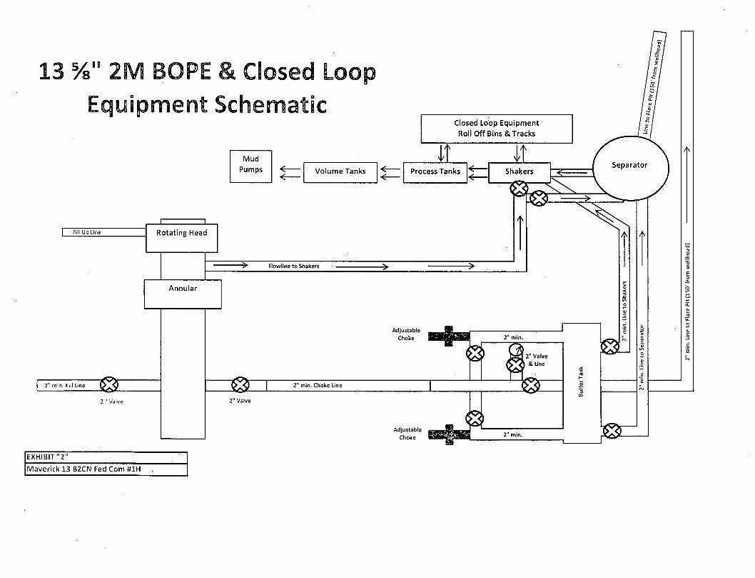
3 Vs" 2M BOPE & Close Equipment Schematic
Fill Up Line
2" min. Kill Line
EXHIBIT "2"
Rotating Head
Annular
Maverick 13 B2CN Fed Com #1H
Closed Loop Equipment Roll Off Bins & Tracks
Mud Pumps Volume Tanks
—^ Flowline to Shakers
33E 2" min. Choke Line
Process Tanks
Adjustable Choke
Adjustable Choke
Shakers
2" min.
| 2" Valve & Line
2" min.
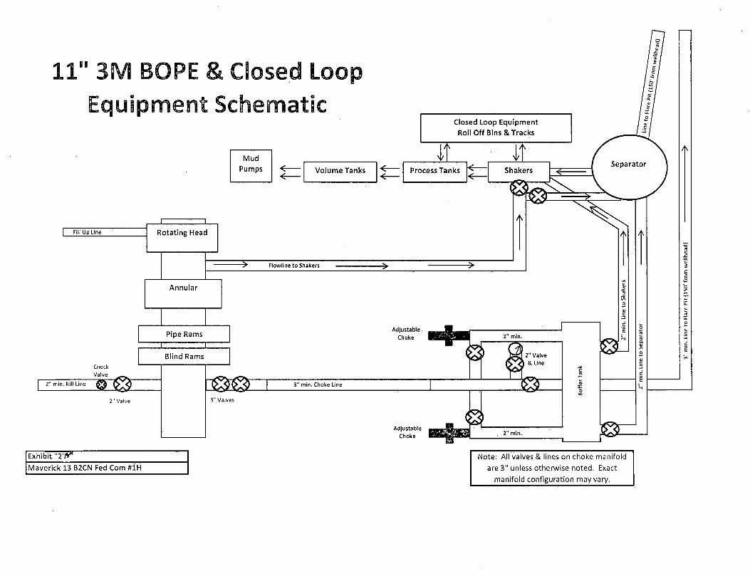
11" 3M BOPE & Closed Loop Equipment Schematic
Fill Up Line
Check Valve
2" min. Kill Line
Exhibit "2'rV
Maverick 13 B2CN Fed Com #1H
Closed Loop Equipment Roll Off Bins & Tracks
Mud Pumps
4' Volume Tanks
it Process Tanks
s Shakers Process Tanks Shakers
K
Separator
Note: All valves & lines on choke manifold
are 3" unless otherwise noted. Exact
manifold configuration may vary.
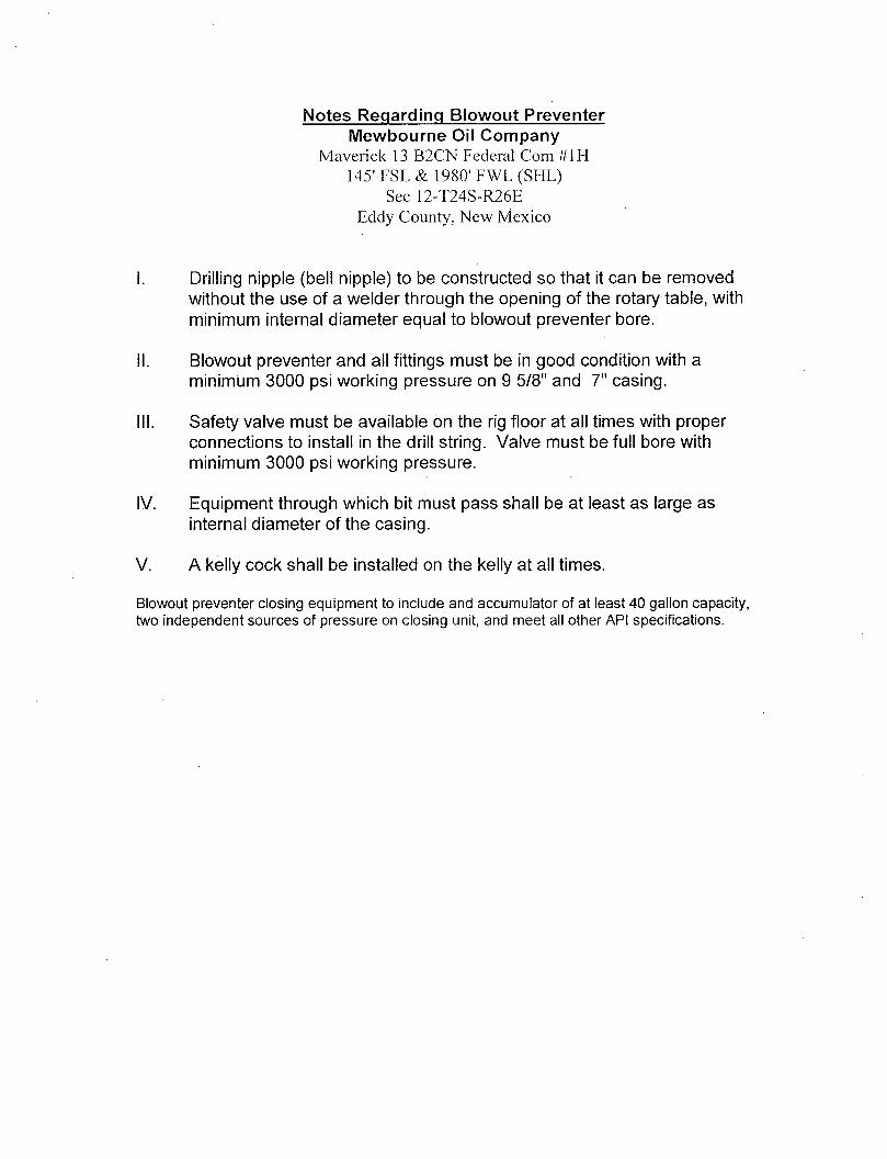
Notes Regarding Blowout Preventer Mewbourne Oil Company
Maverick 13 B2CN Federal Com #1H 145' FSL & 1980' FWL (SHL)
Sec 12-T24S-R26E Eddy County, New Mexico
I. Drilling nipple (bell nipple) to be constructed so that it can be removed without the use of a welder through the opening of the rotary table, with minimum internal diameter equal to blowout preventer bore.
II. Blowout preventer and all fittings must be in good condition with a minimum 3000 psi working pressure on 9 5/8" and 7" casing.
III. Safety valve must be available on the rig floor at all times with proper connections to install in the drill string. Valve must be full bore with minimum 3000 psi working pressure.
IV. Equipment through which bit must pass shall be at least as large as internal diameter of the casing.
V. A kelly cock shall be installed on the kelly at all times.
Blowout preventer closing equipment to include and accumulator of at least 40 gallon capacity, two independent sources of pressure on closing unit, and meet all other API specifications.

H2S Diagram Closed Loop Pad Dimensions 340' x 340'
Mud house Pit
Pit
^ Pumps
Gen Water Water
Fuel DH Parts
North
Road
Roll off bins min. 150' flare line
Primary Wind Direction
Substructure
S3 Top DH
Catwalk Secondai
Pipe Racks
Secondary H2S Egress
Bunk House - 170'
Primary
Co Man Trailer 170'-
ions Exhibit 5
& | = Safety Stati
EE1 j = H2S Monitors
Wind Markers
Mewbourne Oil Company Maverick 13 B2CN Fed Com #1H 145' FSL & 1980' FWL Sec. 12 T24S R26E Eddy County, NM
Warning Signs

Hydrogen Sulfide Drilling Operations Plan Mewbourne Oil Company
Maverick 13 B2CN Federal Com #1H 145' FSL & 1980' FWL (SL)
Sec 12-T24S-R26E Eddy County, New Mexico
1. General Requirements
Rule 118 does not apply to this well because MOC has researched this area and no high concentrations of H2S were found. MOC will have on location and working all H2S safety equipment before the Delaware formation for purposes of safety and insurance requirements.
2. Hydrogen Sulfide Training
All personnel, whether regularly assigned, contracted, or employed on an unscheduled basis, will have received training from a qualified instructor in the following areas prior to entering the drilling pad area of the well:
1. The hazards and characteristics of hydrogen sulfide gas. 2. The proper use of personal protective equipment and life support systems. 3. The proper use of hydrogen sulfide detectors, alarms, warning systems, briefing
areas, evacuation procedures. 4. The proper techniques for first aid and rescue operations.
Additionally, supervisory personnel will be trained in the following areas:
1 The effects of hydrogen sulfide on metal components. I f high tensile tubular systems are utilized, supervisory personnel will be trained in their special maintenance requirements.
2 Corrective action and shut in procedures, blowout prevention, and well control procedures while drilling a well.
3 The contents of the Hydrogen Sulfide Drilling Operations Plan.
There will be an initial training session prior to encountering a know hydrogen sulfide source. The initial training session shall include a review of the site specific Hydrogen Sulfide Drilling Operations Plan.
3. Hydrogen Sulfide Safety Equipment and Systems
All hydrogen sulfide safety equipment and systems will be installed, tested, and operational prior to drilling below the 9 5/8" intermediate casing.
1. Well Control Equipment A. Choke manifold with minimum of one adjustable choke/remote choke. B. Blowout preventers equipped with blind rams and pipe rams to accommodate all
pipe sizes with properly sized closing unit C. Auxiliary equipment including annular type blowout preventer.
2. Protective Equipment for Essential Personnel Thirty minute self contained work unit located in the dog house and at briefing areas.
Additionally: If H2S is encountered in concentrations less than 10 ppm, fans will be placed in work areas to prevent the accumulation of hazardous amounts of poisonous gas. If higher concentrations of H2S are detected the well will be shut in MOC will follow Onshore Order 6 and install a rotating head, mud/gas separator, remote choke and flare line with igniter will be installed.
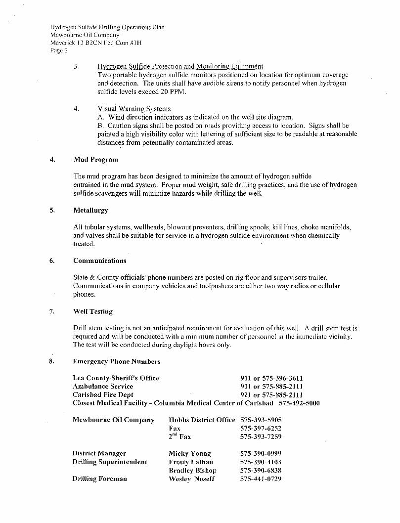
Hydrogen Sulfide Drilling Operations Plan Mewbourne Oil Company Maverick 13 B2CN Fed Com #1H Page 2
3. Hydrogen Sulfide Protection and Monitoring Equipment Two portable hydrogen sulfide monitors positioned on location for optimum coverage and detection. The units shall have audible sirens to notify personnel when hydrogen sulfide levels exceed 20 PPM.
4. Visual Warning Systems A. Wind direction indicators as indicated on the well site diagram. B. Caution signs shall be posted on roads providing access to location. Signs shall be painted a high visibility color with lettering of sufficient size to be readable at reasonable distances from potentially contaminated areas.
4. Mud Program
The mud program has been designed to minimize the amount of hydrogen sulfide entrained in the mud system. Proper mud weight, safe drilling practices, and the use of hydrogen sulfide scavengers will minimize hazards while drilling the well.
5. Metallurgy
All tubular systems, wellheads, blowout preventers, drilling spools, kill lines, choke manifolds, and valves shall be suitable for service in a hydrogen sulfide environment when chemically treated.
6. Communications
State & County officials' phone numbers are posted on rig floor and supervisors trailer. Communications in company vehicles and toolpushers are either two way radios or cellular phones.
7. Well Testing
Drill stem testing is not an anticipated requirement for evaluation of this well. A drill stem test is required and will be conducted with a minimum number of personnel in the immediate vicinity. The test will be conducted during daylight hours only.
8. Emergency Phone Numbers
Lea County Sheriffs Office 911 or 575-396-3611 Ambulance Service 911 or 575-885-2111 Carlsbad Fire Dept 911 or 575-885-2111 Closest Medical Facility - Columbia Medical Center of Carlsbad 575-492-5000
Mewbourne Oil Company Hobbs District Office 575-393-5905 Fax 575-397-6252 2 n d Fax 575-393-7259
District Manager Micky Young 575-390-0999 Drilling Superintendent Frosty Lathan 575-390-4103
Bradley Bishop 575-390-6838 Drilling Foreman Wesley Noseff 575-441-0729
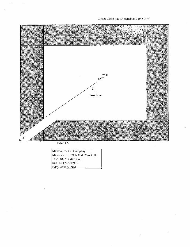
Closed Loop Pad Dimensions 340' x 340'
Mewbourne Oil Company Maverick 13 B2CN Fed Com #1H 145'FSL & 1980' FWL Sec.12 T24S R26E Eddy County, NM

MULTI-POINT SURFACE USE AND OPERATIONS PLAN MEWBOURNE O I L COMPANY
Maverick 13 B2CN Federal Com #1H 145'FSL & 1980' FWL
Sec 12-T24S-R26E Eddy County, New Mexico
This plan is submitted with Form 3160-3, Application for Permit to Drill, Covering the above described weil. The purpose of this plan is to describe the location of the proposed well, the proposed construction activities and operations plan, the magnitude of the surface disturbance involved, and the procedures to be followed in restoring the surface so that a complete appraisal can be made of the environmental impact associated with the proposed operations.
1. Existing Roads:
A. Exhibit #3 is a road map showing the location of the proposed well. Existing roads are highlighted in black. Exhibits #3-#3C are maps showing the location of the proposed well and access road. Existing and proposed roads are highlighted in black.
B. Directions to location: At intersection of Cr-720 & Cr-763, go NE approx.. 1.1 mile on CR-763 to a lease road. Turn right and go East approx.. .1 mile to the two track road. Turn right and go SE approx.. .5 mile, turn left and go east .1 mile. Turn right and go SE 250', turn left and go east .3 mile, turn left and go NE following proposed road 550' to this location.
C. Existing roads will be maintained in a condition the same as or better than before operations begin.
2. Proposed Access Road:
A Approx. 355.47' feet of new road construction will be needed. (Will need to upgrade 695.25' of two-track road will need to be upgraded, Exhibit 3A-3A2.)
B. The maximum width of the driving surface will be 14 feet. The road will be crowned and ditched with a 2% slope from the tip of the crown to the edge of the driving surface. The ditches will be 1 foot deep with 3:1 slopes. The road will be surfaced with 6" of rolled and compacted caliche.
C. Mewbourne Oil Co. will cooperate with other operators in the maintenance of lease roads.
3. Location of Existing Wells:
There are producing wells within the immediate vicinity of the well site. Exhibit #4 shows existing wells within a one mile radius.
4. Location of Existing and/or Proposed Facilities:
A. There are production facilities on this lease at the present time. B. In the event that the well is productive, production facilities will be at the Maverick 13
DM Fed Com #1H battery. A low pressure (under 125#) steel 2 7/8" surface flow line will follow new & upgraded two track roads from Maverick 13 B2CN Fed Com #1H to MOC's Maverick 13 DM Fed Com #1H battery. This line will be within 5' of the lease road approximately 1050.72' in length (route is shown in Exhibit 3A-3A2.
C. All production vessels left on location will be painted to conform to BLM painting stipulations within 180 days of installation.

MULTI-POINT SURFACE USE AND OPERATIONS PLAN MEWBOURNE OIL COMPANY Maverick 13 B2CN Fed Com It/H Page 2
5. Location and Type of Water Supply
The well will be drilled with a combination of fresh water and brine water based mud systems. The water will be obtained from commercial suppliers in the area and/or hauled to the location by
J transport trucks over existing and proposed roads as indicated in Exhibit #3.
6. Source of Construction Materials
All material required for construction of the drill pad and access roads will be obtained from private, state, or federal pits. The construction contractor will be solely responsible for securing construction materials required for this operation and paying any royalties that may be required on those materials.
7. Methods of Handling Waste Disposal:
A. Drill cuttings not retained for evaluation purposed will be hauled to an off-site permitted facility.
B. Water produced during operations will be hauled to an off-site permitted SWD in the area. C. MOC will use a closed-loop system during drilling operations. D. I f any liquid hydrocarbons are produced during operations, those liquids will be
stored in suitable tanks until sold. E. Sewage and gray water will be safely contained on-site, and then waste will be disposed at
an approved off-site facility. F. All trash, junk, and other waste materials will be stored in proper containers to prevent
dispersal and will be removed to an appropriate facility within one week of cessation of drilling and completion activities.
8. Ancillary Facilities
There are no ancillary facilities within the immediate vicinity of the proposed well site.
9. Well Site Layout
A A diagram of the drill pad is shown in Exhibit #5. Dimensions of the pad and location of major rig components are shown.
B. The pad dimension of 340' x 340' has been staked and flagged.
10. Plans for Restoration of Surface
A. Within 120 days of cessation of drilling and completion operations, all equipment not necessary for production operations will be removed. The location and surrounding area will be cleaned of all trash and junk to assure the well site is left as estheticaliy pleasing as reasonably possible.
B. Interim reclamation:

MULTI-POINT SURFACE USE AND OPERATIONS PLAN MEWBOURNE OIL COMPANY Maverick 13 B2CN Fed Com tilH Page 3
i. All areas not needed for production operations will be reclaimed as shown in the interim reclamation layout, exhibit #6.
ii . In these areas, caliche will be removed, the land will.be recontoured to match the surrounding area, and the topsoil from the stockpile will be spread over these areas.
iii . The disturbed area will be restored by seeding during the proper growing season.
iv. Any additional caliche required for production facilities will be obtained from the reclaimed areas.
C. Final Reclamation: i . Upon cessation of the proposed operations, if the well is
abandoned, all equipment and trash will be removed and taken to a proper facility.
ii. The location and road surfacing material will be removed and used to patch area lease roads.
iii. The entire location will be restored to the original contour as much as reasonable possible.
iv. The topsoil used for interim reclamation will be spread over the entire location.
v. The disturbed area will be restored by seeding during the proper growing season.
All restoration work will be completed within 180 days of cessation of activities. 11. Surface Ownership:
The surface of the upgraded two track road is owned by Eugene C. & Alice K. Hood, 1142 Black River Village Road, Carlsbad, NM 88220. Mewbourne has reached an agreement with the land owner and a surface use agreement is in place. A copy of this plan has been sent to the Hood's.
12. Other Information:
A. The primary use of the surface at the location is for grazing of livestock.
13. Operators Representative:
A. Through APD approval, drilling, completion and production operations:
N.M. Young, District Manager Mewbourne Oil Company PO Box 5270 Hobbs, NM 88241 575-393-5905
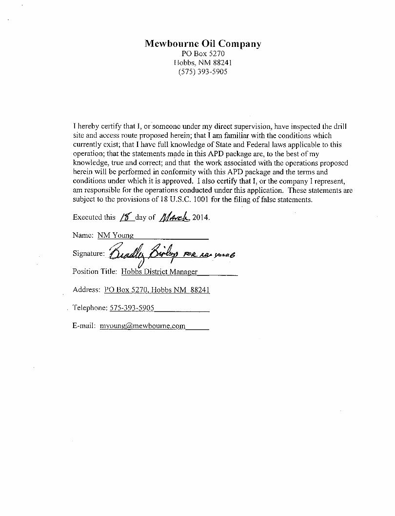
Mewbourne Oil Company PO Box 5270
Hobbs, NM 88241 (575)393-5905
I hereby certify that I , or someone under my direct supervision, have inspected the drill site and access route proposed herein; that I am familiar with the conditions which currently exist; that I have full knowledge of State and Federal laws applicable to this operation; that the statements made in this APD package are, to the best of my knowledge, true and correct; and that the work associated with the operations proposed herein will be performed in conformity with this APD package and the terms and conditions under which it is approved. I also certify that I , or the company I represent, am responsible for the operations conducted under this application. These statements are subject to the provisions of 18 U.S.C. 1001 for the filing of false statements.
Executed this f l f day of / f / j v t z L , 2014.
Name: NM Young
Position Title: Hobbs District Manager
Address: PO Box 5270, Hobbs NM 88241
Telephone: 575-393-5905
E-mail: [email protected]

I0OK 971
ASSIGNMENT AND BILL OF SALE AGREEMENT
This A5SIGNMENT;AND BILL OF SALE AGREEMENT ("Agreement") dated effective November 1, 2013 ("Effective Date") is made by and between Chevron U.S.A. Inc., a Pennsylvania corporation with ail address at-R O. Box 2100, Houston, Texas 77252-2100 ("Assignor") and Mewbourne Oil Company, a Delaware corporation, with an address at P.O. Box 7698, Tyler, Texas 75711 ("Assignee");
RECITALS
A. Subject to the, reservation of overriding royalty interest arid the other terms and conditions in this lAgreementi .Assignor wishes to. assign to Assignee, without warranty of any kind, either express ^ i f t ^ l i ^ . ^ l ^ A i W g i i o r j i 'right; title and interest in that certain oil and gas tease described in
B. Assignee..wishes? to acceptitroni Assignor the assignment described in Recital A.
AGREEMENT
i . DEFINITIONS, INTERPRETATION AND EXHIBITS
LI Definitions. As used in this Agreement, these words or expressions have the following, meanings:
"Affiliate" of a Party shall mean any Person that, directly or indirectly* through one or more intermediaries, controls or is: controlled: by or is under common control with such Party. For- purposes of this definition, "control" means ownership of fifty percent (50%) or greater of the voting;interest. (stock or otherwise).of such entity.
"Agreement" has the meaning given in the introductory paragraph of this Agreement.
"Assignee? means the Person defmed-as "Assignee" in the introductory paragraph of this Agreement.
"Assigned Lease" means the Oil and Gas Lease described in Exhibit. A and the lands covered thercby.
'Assigned Property Agreements" means all covenants, terms, and provisions, express or implied; contained in the agreements, leases, easements; permits, commingling authofizations'Xif applicable)* operating agreements, and all other agreements pertaining to Assignor's inlerest in the Assigned Lease.:
'l^ssi^or^'imeans .thfe Persotr defined as ^Assignor" in the/introductory paragraph of this Agif bWffiti •
'Assignor Groap means Assignor, Assignors Affiliates,••IMnt interest Owners and their :4il^^''in^iii&iyweetiMS, officers and employees ofall of them.
(Siairri" means; any claim.:liabiluy, loss, demand, dainageSi Lien, cause of action of aiiy,
Jl^aMcSsfeiflf•.liHgaUprt;-'t)f.the Person asserting the Claim), whether arising by law. Contfaqt,;tftit, voluntary settlement or otherwise.
1

«o* 971 w,1084
"Effective Date" means the date/time defined as "Effective Date" in the introductory; paragraph of this Agreement.
"Exhibit" means a 'document referred to in Section 1.3.
"IndemhiteefsY' means each Person who is a member of Assignor Group.
"Joint Interest Owner" means a Person: (including a co-interest owner, joint venturer, partner or corlesscc of Assignor) who shares an economic interest in common with Assignor or an Affiliate of Assignor.
•'Laws" has the meaning set forth in Section 7.7.
"Pen" rneans;charge. encumbrance or similar right^^ avaiiable'to creditors at law, to secure debts owed to them.
"NOftivF means: naturally oceu rring rad ibactive material.
"Party": means Assignee or Assignor and 'parties" mean both" of. them;
"Person" means' an individual, corporation, company, slate, statutory corporation, goyeriime"nt;entity:6r anyfother legal entity;
''Personal Property" means Assignor's personal property or eqwpmeritiassociated: with fiSy^WelTsj
'^Wells'' means:all oil wells,; gas wells^ ^t-^^-i&^stf^lIs>!i^^i to 'Wi»]1i9artd other '^U'^^KSU^^I^gJ^id or unptogg^);!^ or forif&l^' used ;tn connection ,wjftt.p^ratiposmtne Assigned bsasfr or any • wdis which are-drilied irijlhe - i N i t u ^ . c ^ t ^ ' i ^ ^ i ^ X i # s ^ i .
i i i . interpretation. Sjhiessv the, confer all' of the /following applytd;the:iriterpr^
(A) fheipluraljand.sin^
(B) Thema^uiine.-feininine;ahd neuter gerideri each M
(G) The word "or" is not exclusive.
(D) The word "includes" and "including" are not limiting, but are terms of enlargement so other items or components are; includable although not specifically expressed.
(E) References 10 matters "arising" ;(pr which, '?ariSe"v or ^ i s e 0 ?."pui of this Agreement" include matters which arise in connection with this Agreement or have a causal connection with or which flow from this Agreement or which WoulB hot have arisen or occurredI butfpr-ttie?enteri^ performance of or failure to perform obligations under this Agreement.
2

»« 971 fMf]085
(F) The headings in this Agreement are included for. convenience and do not'affect the construction or interpretation of any provision of, or the rights or obligations of aParty under,.this Agreement.
(G) If a conflict exists between any provisions of this Agreement as they apply to Assignee, the provision that imposes the more onerous obligation on Assignee prevails to the extent of the conflict.
1.3 Exhibits
(A) Exhibits A and B attached to the body of this Agreement is an integral pan of this Agreement and is incorporated by reference into this Agreement.
(B) If a conflitt-exists between,the:bbdy.'df-tKis.Agiwi^t^and^Kibiits A and B, the Bodyprevails "to.the exfenrpf the cp
2. CONVEYANCE
2.1 Assignment. Assignor assigns ;tp Assignee, and Assignee: accepts from Assignor, wtKbutf^arra«ty;qE i ^ ^ r j ^ i ^ i ^ ' % ^ | | i ^ - ^ . . ^ j ^ | ^ ^ nght title ihd;inteireSt j ^ t h % i j ^ 8 l ^ | ^ £ ^ . subject'ftb Assignor's ii^!^^>Qf>|Re^QVBRidtog'
". ip^S%' in|erestr'describ1ed: below <and ali of- the dther. ' j 0 ! i ^ ^ f ^ - f ^ ^ ' ' A ^ e i ^ c ^ J S s s i ^ f i ^ ^ t ^ ^ j ^ j withcfCit ^ f ^ ^ ^ ^ ^ . l l ^ l f - t ^ ^ ^ ^ ^ : f i i . iniplied, -all; Of; Assigrioris.righ titl'e.and interest'in.the Aisigned.Property Agreements.
Biil-rqf Safe A^ignofisells tp-^s|ig§ee, and AKign^e a § l § ^ ' l ) ^ . A ^ l | ^ ^ " ^ ^ H i t warrantyittfjany^^ and interest ih>and:t6;'ali WcllsTandWfsohal 'Property.
2.3 Overriding Rpyalty>Reservation.
(A) Assignor hereby excepts ' ^ . i f ^ i ^ i p ? ^ ^ i | i ^ f § $ j ^ t interi^equal to the difference between (i) 25%; . and (ii) the aggregate amount of all lessors' royalties, :o vcrriding royalty .interests, production payment'interests and similar ' ^ ^ g | ; ^ ^ i J ^ g ^ | ^ ^ ; ^ t i p i H g | | of^ffieiEflecti^^at^' pfallpij, gas,.
Assigned tease. Such' share.*6f prb'ductioii' sh^?D©delivefedVtfc its: successors and assigns, free, and clear of all rc]j|i5y|hd ;e£p$ns§s of drilling, deveippmenM^ ahd.nwlcetin|j& expenses of ^ydr&ing; Wns^pging; boosting, compressing or otherwise processing such: oil, gas,, Ijguid hy&pcafbpns and other minerals in rdrdbr to make :the same marketable]!:: except the taxes on or'attributable to prpductipn;.6r income therefrom.
(B) If Assignee or.any Affiliate of Assignee: or-related; party'securesfan extension or renewal ofthe Assigned IJea^ prior to the'termination bf.Uie Assigned Lease or within 1 year thereafter, or if Assignee or any Affiliate of Assignee or related party secures a new lease covering any or all Of. the lands covered by the Assigned Lease prior to termination of the: Assigned Lease or within 1 year thereafter:
3
(1) The overriding royalty interest excepted and reserved by Assignor will attach to such extension, renewal or new lease.
(2) Assignee will execute and deliver to Assignor a recordable instrument* on a form acceptable to Assignor, which evidences Assignor's ownership of such overriding royalty interest in the extension, renewal or new lease.
(C) If the Assigned Lease covers less than all of the oil and gas in and under the lands covered.thereby, or i f Assignor owns or is assigning to Assignee less than the. full interest of the original lessee in the Assigned Lease, the overriding royalty interest reserved by Assignor herein shall be proportionately reduced, •pe.pyerriding royajly interest ;shall be subject to. any governmentally approved cooperative br unit plan of development or operation or commuhitizatipn or pther
;.a'gn&ment ofdesignatipn.f^^ prorat|on:unit;under theniles or iregulatipns ofrthe governmental authority having jurisdiction to which the Assigned Lease is now committed or may heieal'ter tie comiititted, and in' such
le^^kl^ioynnding 'tjoyaity interest shall.be computed and paid .on the basis of the. oil and: gas allocated: to the lands pursuant to the terms of* the- plan or .agpSWeni
2.4 a ^ ] p » ' ' ^ ^ ^ ; ' ^ G ^ ^ I ^ i ( h Established Contracts. Assignee will obsCTye; and ^ o t ^ ^ . ^ m { ^ l , i ( ^ ^ ^ U } feri&V.and provisions, express o t s i ' j i ^ i i i ^ ^ i i ^ ^ ^ : . i i i | tfie Assigned JWperty 'A^ ex'p' i iK$ly'sj |bj^,%^)V#^ Assigned Bropeft^. A^eemehts-whether or h A^Sf t en j : .^lylneliW^? •sllw^ an'd:be;.resppnsibievfor all ;p^li|a^Qiis^$if'^|^QF, acemiijg^usaeri the; 'Assigned iKoperty Agreements on and after the Effective 'Sate. • ^ i g ^ ^ ^ i t ^ ^ ^ . ^ i ^ $ M # > I ^ S ^ f l ^ . adopts* ^ f i ^ a s a ^ j f f i n n ^ ^ y : AssjgMed p p p e r ^ - ^ andirom the;fiffectivc pate^ :a^e^;t0«b$3t§s$$it$d •iEi3ft' ljSr%^ i fib ^^ i| .i U '>to^ s«t<efi< ssijg,i tii. •Pirop iri - grec^nii tAand:'| fe<BS tbfassifm'e ipjof^sslg^^
2i5 RlgfefctO Audits •A^j ' j j^ 's^!l 'b^ ' ' th&'i^i t<ti9 audit A^ig^-S-b^ls^andiiie(^^V<H^ jjfe5"yearitp;dfte ^'.ta^^^ioc^icJKt^yoi^ ffiisr-Agxeemehtr^^ the-payment vahd ealbulationKdP Assignori's j ^ ^ | d ' 6 ^ ' r ^
3.1 ' ^ ) ^ ^ f ^ t s > | % ' , < ^ i ] n j g . and completing any Well on the Assigned Lease, Assignee agrees5to-3eiiS^ On
. fohitiii^
.3.2 Tfie'-Vyell Data'shali b^ dyi
Chevron U:S.A. Inc. PaQ^oxSiOO Houston, Texas 77252-2100
4

IOGK 971 H«1087
4. NO WARRANTY OR REPRESENTATION BY ASSIGNOR
4.1 This Agreement is made on an "AS IS, WHERE IS" basis, "WITH ALL FAULTS," and WITHOUT WARRANTIES WHATSOEVER WITH RESPECT TO ANY INTEREST TRANSFERRED, EITHER EXPRESS OR; IMPLIED, it being expressly agreed by Assignor and Assignee; that ASSIGNOR MAKES NO WARRANTIES OR REPRESENTATIONS WITH -RESPECT TO ORIGIN, QUANTITY, QUALITY, CONDITION, MERGHANTABlLITYr FITNESS ;FOR ANY PARTICULAR PURPOSE, SAFETY OF EQUIPMENT, COMPLIANCE WITH GOVERNMENTAL REGULATIONS, TITLE TO PERSONAL PROPERTY, TITLE TO REAL PROPERTY, THE QUANTI-TTyi VALUE OR EXISTENCE OF RlESERVESrOF'OILf G IBLE OR RECOVERABLE FROM THEl ASSIG^D LEA OR CONDITION OF THE ASSIGNED LEASE, WELLS AND PERSONAL PROPERTY.
4.2 All descriptions iejt: foi^i-inltiiis Agreement a n d ^ r n ^ n ^ ^ l ! ^ ^ ^ ^ ' ^ ^ ^ ^ Assignor before or after the Effective Ba.it bbrfcfemingi the: Assigned ;Lease. and the ppei-atipn.^^ hayenot;^ corisfiratevai-represen A sigho'r, and ;ahy: reiiahce;;6n same 'vA ij SS*WiflSB^54f- - i l f ^ ^ ^ ^ f i sple' nsKiiihd liability:
5. ASSIGNEE'S ASSU>^ION:OF'RES^
5.1 Assignee aeimpwjedges ihatcthe Assigned Lease lta$...'|) e«i:'jas tiliI eiWn*^W-:vii,ii»"' oil, gas, and/br waiter prbductibn; transpbrtatibn,; treatment; storage; "disposal or other, pperatipns and may1 contain ;NORMi ^b^tps, and;; other- substances', ppjjutants. or cOntaminaiitsrai.a re'sult'of such operatte ahd/pf gas wells"* IpitsV IfahdfillSi flpwlines,' pipelines; wdtr 'w.tlUi 'stimpli and;6ther materials and equipment.
5.2 Assignee assumes respbnsibility'for NORM, &b^tes~;a^ oohtaminanb,;:and iknowii- and unknown oil. and/or gas wells, •pjtsi.Jandiil'ls; Bowlines, pipelmeis; ^ Lease.
5.3 Expenses and Recording.
(A) Except as otherwise specifically grpyided; all fees, costs . and; expenses incurred by-'Aisi^of-^-'ASi^^Be-'in negptiafing'mis,Agreed transactions contemplated: by. thfe the same, including legal and accounting fees, costs and expenses.
(B) Assignee will be responsible for the; filing' and recording of this Agreement, conveyances, or other instruments .reo^i^ to Assignee, and Assignee will Bear -all- required •'diXjumentar-y; .filing and recording fees and; expenses incurred: in !;<Mnite bn:''''with' same. Assi^eeishall furnish to Assignor a certified: copy: of this Agreement, conveyances or other instruments so recorded.
5

971 ,»10.88
6. PLUGGING AND ABANDONMENT OF WELLS, REMOVAL OF STRUCTURES AND EQUIPMENT, TREATING AND BACKFILLING PITS, RESTORATION OF SURFACE.
6:1 Assignee agrees to assume all responsibility for the following:
(A) plugging arid abandonment ofexisiingand/orfuture Wells,
(B) the removal of structures, facilities; foundations, wellheads, tanks, pipelines, flowlihes, pumps, compressors, separators, heater treaters, valves, fittings, machinery and; other materials and equipment of any nature located on the Assigned Lease,
(C) treating and bac^
(D) restoration, of the surface;as nearly as practicable to its original condition or as may dtherwise-lrc rc^ or by law.
7. GIAlMSj'LIAfllt
7:1: INTENT OE INDEMNTCpf PROVISIONS. .The Parties agree to allocate between themiresponstbiltry for all.GJaims as set out:below..
7.2 COMPLIANCE'WITH'EXPRESS NEGLIGENCE-RULE. All of Assignee's release, defense; indemnification;; hold:harmless and assumption obligations ;in; this Agreement apply whether or not the'underlying claims arose solely or in part from the gross, active, passive, .sole-- or concurrent' negligence, strict liability; regulatory liability; statutory liability;-or fauluof Assignor or, olher'Indemnitees:. Assignee acknowledges that-this statement complies with the express negligence rule and ls conspicuous.
7.3 ACTS OF INDEMNITEES ?RIOR TO EFFECTIVE DATE. All of Assignee's •release; defenseiandsmdemnity obljgalions apply-without limitation to actsiand omissions of Indemnitees,on or relating-to;.the Assigned Lease andAssigned Property Agreements occu'mng:before the;EffecUve;Date
7.4 PLUGGING AND ABANDONMENT OP WELLS, REMOVAL OF STRUCTURES AND EQUIPMENT, TREATING AND BACKFILLING PITS, RESTORATION OF SURFACE. Assignee agrees to release, discharge, defend, indemnify and hold harmless •'mdemniteess agamst'r.alh Cnaims .arising: from Assignee's breach or failure to comply with.thetrequirements of Sectionifi.
IS TAXES. Assignee agrees to release, discharge, defend, indemnify and hold harmless Indemnitees against all Claims arising from; any sales: or use taxes -assessed against Assignor by,any;.taxing^uthonty with respect of the. sale,oftheAssigned Lease.
7.6 GENERAL INDEMNITY. Assignee agrees to release, discharge; defend,' indemnify and hold harmless. Indemnities against; all Glaims relating to the Assigned Lease and the Assigned Property Agreements pertaining to same that may be asserted or filed on or after the Effective pate.
7.7 ENVIRONMENTAL. CLAIMS. Assignee agrees to release, discharge, defend, indemnify and hold harmless Indemnitees against all Claims relating to the.physical and
6

nor 971 »« 1 089
environmental condition of the Assigned Lease, including claims involving NORM, asbestos,.and other substances; pollutants or contaminants, claims involving known and, unknown.oil ahd/qr gas .wells, pits, landfills, flowlines, pipelines, water wells, sumps, and other materials and equipment located thereon, and claims arising under any federal, state, tribal, or local law or'.regulation ("Laws"). The Laws include The Comprehensive Environmental Response; Compensation, And Liability Act. The Resource Conservation and Recovery; AtCTh'e Glean Water Act, The Safe Drinking Water Act, The Hazardous . Materials Transportation Act, The toxic Substance Control Act, and all amendments to such'acts.
8. CONFLICT OF INTEREST. No director, employee, or agent of-eiiher Party will give or receive; any commission, fee,; rebate, gift, or .entertainment of significant cost 'or value in connection with this Agreement. . For two. years after execution of this Agreement; any r e p r ^ n t ^ may audit; the applicable; records of the other Party solely; fprthe;-^ prqwsjb^ Agreement.
;9. GOVIJRftiNG- LAW. This Agreement :is governed by' and interpreted under the. laws of the Statef^
"10". NQ^GES.; :AU;.!notiees n^uire'd.,:6r; :peiti^^tuid^i'f'Ais. Agiroment. must;berin '.\ynting and;
nqtfc.e;Ki''op^
11. PJPJJG A N N O ^ required by law. a Partyrshall nojjisOTrejam/.^
12. railU);P;ARTY'RIGHTS';. J&ccep't;as;olherwise^ j ^ r^^^ tn iS ' ^g^n t^ t r l i i ^S i^M^ls undjir Uiis A l g ^ n ^ t ^ . ^ y ^ f p ^ e . f^ '°p^is}d| 'df Ag^meiit:: " '
13. A ^ f & N M E N T ; 'ferrij^B3;qf atheriP^y may be assigned in wKole-.or m p ^ ; The'tenris pf this •Agrtei^'nt, will be bTnd.ing- upon and, inure to the. benefit of the "Parties jnd meir. heirs, succ^b^
A | ^ | ^ ' t p $ j ^ . ^ssi|ned<l!e^r^ ibAjragno^^ for pWohnance o ^ obljgatiqns-under this Agreement. Any future assignments of the Assigned Lease .will not in; any way diminish,, compromise, extinguish, or effect: airdease^bf1
A^siglioSssnghlsjag^^sT, A^i ig i i^ ; ,its successors; or assigns, or the obiigatibrisj'bf A|sig^ee,.;.itsi SUccwsqrs;or!&si'gn^
14. GENERAL PROVISIONS
14.-1' Prior Agreements. This-.Agreement; comprises the complete and exclusive agreement between the Parties regarding'the subject matter of this Agreement; and supersedes all oral ajid;wrifteri;CO representations or agrremeiife in relation to.thatjsubject!^
7
971 „«1090
14.2 Amendment. 'This Agreement may not be amended orally or by performance. No amendment to this Agreement is effective unless . made in writing and signed by authorized representatives ofboth Parties.
14.3 Waiver. Assignor's failure to pursue remedies for breachof ^ this:Agrecmcnt; or payment by Assignor of invoices, does not cpnstitutea waiverby Assignor of any breach of this Agreement by Assignee or raise any defense against Claims againstAssignee for breach of this Agreement; The waiver or failure to require the performance of any covenant or obligation contained in this Agreement pr'pursue remedies:for breach/ofthis Agreement does not waiyea later breach of that cbvehant'or bbligationi
14.4 SeyerabUity. Each provision of this Agreement is severable and if any provision is determined to be invalid, unenforceable or illegal under any existing or future law by a court, arbitrator of cpmpetejif jurisdiction.or by operation of any applicable,;law, .this invalidity , unenforceability or illegalityi dpes not impair the operation of OT-affect those portions of-this -i^^«eifMntv-that . ^ ^ t ^ W i i f ^ ^ S t o ^ ^ ligalJuriless the deletion pf suph provision, ;ttr--',(0<a;^tS; wou^d: resuli- in ; such! ;a materia), .change so as to cause completion;pf^
1'4.5. iCbunter^ w h j c h , ^ p^andVtb&siiu^ urilessa^d'uh;^
14:6 Topical Ifedings.j ' ^ ^ t ^ f j i M f | p p ^ . ^ B d in this; Agreejrierit are-fpr'convenience only and will not be construed as'having any substWiye;sighifi;cance;p:r all Of the jiio^ODS'-'-b'teinS W^tsn^^G'K\Stmg: tei-any- topic fare; to>;b£ fpurid inftaiiy particular section.
\%~7: Survival- Despite tiermifiatfe all f p ^ ^ | ^ a ^ . •.Ag^ngitj;. c j ^ $ n | i g . -^|^^^ij^;){«>4iraAHe$u releases- and; ihdernnities.j an|i all proyisionssrelating toaudi^^^ disclaimer o f - c e ^ jiTOtatibns of ;lia|ijity,: ;r||ewi6n ;and jitepectipn vpf r^qrds,: a ^ ^ . ' l i ^ i ^ l i ^ i -aid governing jaw,' ; a ^ ^ ) - ^ i ^ ^ f $ ^ > j f > . : ^ i $ K arose .pripr.ip' -QE^ie^bn.^^fnsna^oa; survive; j i f d e ^ Other^S'SIM^^
l!4-8 Autb>ri^,ifepresenfefrc3; B 'chiParty; represents andSwarrants'idiat :the Agreement has b^nVdffly^ constitutes its legal, valid; and binding obligation enfprpeaDie in; acco'rdance?w!ith its ten-ns, .and? h p ^ ^ 8 f ; ^ - ' : b f f i S ^ execution; delivery,, and-performance^
14-.9 Further Assurances. Tlie Parties^ suchfuft^ reasonabiy/required'orMppropriaterto eyiden^ Agreement or to show the ability: to party pu t;th'B'inteht-and.»purpb b'Mis'Agreement. The provisions of this STCtiphwi^
14.10 Coverhaiental Forms. Separate forms shall be executed contemporaneously by the Parties with this Agreeirient on the appropriate United StateSf J^partmen
8

971 1091
Bureau of Land Management Form in sufficient counterparts to satisfy applicable statutory and regulatory requirements. Those forms shall be deemed to contain all ofthe exceptions, reservations, warranties, rights, titles,, power and privileges set forth herein .as fully as though they were set forth in each such form. The interests conveyed by such Separate forms are the same, and not in addition to, the interest in the Assigned Leases assigned.herein.
IMPORTANT NOTICE: THIS AGREEMENT CONTAINS PROVISIONS REGARDING INDEMNITIES AND WARRANTIES THAT EXPRESS THE AGREEMENT OF THE PARTIES CONCERNING CLAIMS ARISING OUT OF THtS AGREEMENT.
The Parties jiaye executed this . Agreement in; triplicate; asxeyidehced by the following signatures of authorized representatives; oftKeiParties:
ASSIGNOR:. Chevron UlS.A. Inc..
ASSIGNEE:
Naine: D.L. Sleeper
Title:. Attorney-in-fact
hme: James Allen Bririron
Titter ,Aftori%y>m;Fact'
ADDRESS FOR NOTICES:
P. O: Box 2100 Hbustph.'Texas 77252-2100
ADDRESS FOR NOTICES:
500 W.Texas, Suite 1020 Midland, Texas-79701
Attention: Land Manager Attention: Land Manager
a

971 ,«1092
STATE OF TEXAS
COUNTY OF SMITH
vas acknowledged before me on the IW day of December, 2013 by James Allen ppration on bel
/ jt
This instrument was i Brinspn* as Attbrney-ini-Fact of Mewbourne Oil Company, a Delawaiyc rpc^ation on behalf of said corporation.
My Commission Expires: ^ j ^ * •?^ ,-DO'i~7
Notary Public, State of Texas
STATE OF TEXAS
CQUNTY OFflARRIS
This instrunwnt-was acknowledged.before me on the . Iv^ay of December; 201-3 by D.L. Sleeper.-as Atipmiy in-Faetr
ublic, State of Texas
My CpmrnissibniExpires;] , ANQElAiRENEE, HARMON
MyXommfs&KExpiiei ' • Moy 01, 2017 . :
10

•oor 97) P l s t]093
EXHIBIT A - ASSIGNED LEASE
Attached to and made a part of that certain ASSIGNMENT AND .BILL'OF SALE dated effective November 1, 2013, by and between Chevron U.S.A. Inc., as Assignor and Mewbourne Oil Company as Assignee.
ASSIGNED LEASE
All of Assignor's right, title, and interest in and to the following/Oii and Gas Lease:
LEASE SERIAL NO.: NMNM 111528 LEASE DATE: May 1,2004 LESSOR: United Stales of America . , . ,. LESSEE: Ghalfant Properties Inc. : * :
RECORDED: Book 549, Page 1224, Eddy County Records DESCRIPTION: N/2NE/4, SW/4,.N/2Sm, SW/4SE/4>of Section 13, Township 24S, Range 26E,
Eddy Couhty;i:New Mexico, cbntaiW
FiTOOF.FAHroiTA
11
I

.op, 971 ,«109.4
EXHIBIT B - WELL DATA
1. Daily drilling reports 2. Daily MWD logs arid/or borehole steering plot 3. Mudlogs (MD & TVD) 4. Wireline logs (MD & TVD) 5. Core reports (if applicable) 6. Directional survey 7. Completion reports including flow 8v DST's and/or RFrY(Final)
END OF EXHIBIT B
R|GKP;TIOM; HO». 1402B97 . W t i i i OF
12

Form 3000-3 UNITED STATES (July 012) DEPARTMENT OF THE INTERIOR
B U R E A U OF L A N D M A N A G E M E N T
ASSIGNMENT OF RECORD T I T L E INTEREST LN A LEASE FOR O I L AND GAS OR GEOTHERMAL RESOURCES
Mineral Leasing Act of 1920 (30'US.C. 181 et seq.) Act for Acquired Lands of 1947 (30 U.S.C. 351-359)
Geothermal Steam Act of 1970 (30 tXs.C. 1001 -1025) Department of the Interior Appropriations Act, Fiscal Year 1981 (42 U.S.C. 6508)
FORM APPROVED OMB NO. 1004-0034 Expires: July 31, 2015 Lease Serial No.
NMNM 11.1528
Lease-Effective Date (Anniversary Date)
May 1,2004
New Serial No.
1 . Assignee* Mewbourne Oil Company Street P.O. Sox 7698 City. Slate, Zip Code Tyler, Texas 75701
*lf more than pne^assign^ £ 3 separate attache'd-sheefof-pape h
PART A: ASSIGNMENT
l a. Assignor Chevron U.S.A. Inc!
and tist.the ntmie(s)OTd a<!dress(es) oPallidditiphal assignees on page 2-of this form or on a
TTiis'recofdltitle ^ \Y I Oiland'Gas Lease, or |: |-Geothermal Lease
Interest conveyed: -(GkjiQKon 'QrZ'l&ifi, qs d^p^pridte) EZJ RecprdTjtle, .Oyerriding.Rpyalty similarinterestsprpayments
2; Thisrassipmenticb'nv ; il&rid jSesSi'ptiori: •...
.Additional spacejo^^ other than this form',>uch^
. Percent of Interest Ovfljeo!' 'Cpriveyed: Retaineil
PeTeenWf Oy.eriiaitfg;i&y^ : ;Siroi|afTtnfjrests
Reserved Brevibusly reserved ,
or'conveved f-'
Tbwmship.2^ Eo%xSkiunt i.i .'HexKS ,SecUofrl&l^t^ c6nlaining^60;p0 acres;'mpre.;pr/less.
1®% 100% •fl ora equal tb the difference between 25%and existln'g burdens as referenced In the county assignment
FOR BLM USE ONLY - DO NOT WRITE BELOW THIS LINE UNITED STATES OF AMERICA
This assignment is'.approved[ solely for a'dmiriUtratiyeipurposes. Approval docs not warrant that either party to this assignment holds legal or equitable title to this lease.
• Assignment approved for above described lands;
Assignment approved effective ^
I I Assignment approved for attached land description
[~] Assignment approved for land description indicated, on .reverse of this form
By
Bureau of Land Management (BLM) (Title) (Date)
(Continued on page 2)

Pan A; (Continued) ADDITIONAL/SPACE for Names and addresses of additional assignees in Item-No.!, if needed, or for Land Description in Item 2, i f needed.
PART B - CijRTjWCATIOt<! AND REQUEST: XfOR' APPRO^At
1'. fni&A&ignof 'o^^
otfeftvispjinx^^
M Iner^ teasing Act. the
-3'.. Assi^n&'f Sijnahff ^^ herein: •
Fdr:geothenha]:assi|jimcnts, an overriding rc^alty.may not be less than one-fourth (1/4) of one percent of Uie valuo of output, nor greater than 50 percent of the rateofroyalrydueVtothe^
rce ' r i i f ^
Executed this.. . i December
.day of 20 13 Executed this day of
December 20.
13:
Name:pf;Assignbr asihovTOWcurreStlease: Chevron U.S.A. I n t
(Ple4se;type on print) :
Assignor (Signature)
Assignee
(Signature)
or
Attorney-in-fact
1400-Smith Street
(Signature)
Houston
(Assignor's Address)
Texas
(City) (State)
or
Atlomey-inrract
(Tide)
(Signature)
77002
(Zip Code)
Title U.S.C. Sec... 1001 makes it a crime for any person knowingly and.wi|!fu|ly in make to, any Department or.agcncy of the United States any false; fictitious, or frauduleni'stateme'nls or representations as to any matter within its jurisdiction, : ' „ _ _ _ _ L _ _
(Continued oh page 3) (Form 3000;3, page 2)

F A R T C - G E N E R A L I N S T R U C T I O N S
1. Assignor/Assignee must complete Parts A1 and A2 and Part .B. All parries, to assignment must sign as follows. The assignor© must manually sign 3 original copies and the assignee(s) must manually sign at least 1 ofthe 3 original copies. File three (3) completed copies of;this proper BLM office for each assignment of record title. For a rjansfer.ofoverridingroyalty imeresCpayment out of production or other similar interestor payment, file one (!) manually signed copy "ofthis -form'. The required/filing fee (nonrefundable) must accompany the assignment. File assignment within ninety (90) days afterdate of executionofassignor.
2. Sep'aratefqrmmust beused foreach lei^e being-affected by this assignment and.for each type of interest conveyed.
3. In Item No. 2 of Part A, describe lands affected (See-43 CFR 3106,3135 or 32'tl). For columns b, c, dv ande. enter'the ihteresfexpressed;^ .ass]gns. bhe.quartero
4; I f assignment is to more-'th^ e;;aiid friext to me respective inter&f being conveyed. Also, list names arid addresses of aiiy additional assignee's) qn-reyerse ofjthis form,^
Si ifan^paymentOutof pro^ crca^/M^pthe^n s u ^ p j ^ K ^ o r i r ^ this assi jrnCT.C i . n c l ^ pertinent termsias provided uride^^
6; The-lease ,ae^^ 43 CFR 3106 and 3 2 4 1 , * " "
7. Assignmentivif approved, ^ prop^BLM:q'ffiee; Tfabqnd i^n^^B^^^^f^-Tiit^t-l^'^^i^i^^'^Ni^'to^jE^^x^iil-^^'€lKr^E^ijs|ttn^it;
8. - i^^v^: .9Y:f^j^n]^t ;p]C!!e^t4^Q^ !,QQ '-Of:a;po$^ of tte retained ahd;te anjiiyeRsary-^
9. Qv^ffidingrqyajf^jpaymenP^
(Coiilinued on page 4) ( T o r T n 30OO-3, page 3)

PECOS DISTRICT CONDITIONS OF APPROVAL
OPERATOR'S NAME: Mewbourne Oil Company LEASE NO.: NMNM-111528
WELL NAME & NO.: Maverick 13 B2CN Fed Com IH SURFACE HOLE FOOTAGE: 0145' FSL & 1980' FWL
BOTTOM HOLE FOOTAGE 0330' FSL & 1980' FWL Sec. 13, T. 24 S., R 26 E. LOCATION: Section 12, T. 24 S., R 26 E., NMPM
COUNTY: Eddy County, New Mexico
T A B L E O F C O N T E N T S Standard Conditions of Approval (COA) apply to this APD. If any deviations to these
standards exist or special COAs are required, the section with the deviation or requirement will be checked below.
I I General Provisions I I Permit Expiration I I Archaeology, Paleontology, and Historical Sites I I Noxious Weeds [X] Special Requirements
Watershed Protection Requirements Communitization Agreement
I I Construction Notification Topsoil Closed Loop System Federal Mineral Material Pits Well Pads Roads
I I Road Section Diagram IE1 Drilling
Cement Requirements Medium Cave/Karst Logging Requirements Waste Material and Fluids
^ Production (Post Drilling) Well Structures & Facilities Pipelines
I I Interim Reclamation I I Final Abandonment & Reclamation
Page 1 of 19

I. GENERAL PROVISIONS
The approval of the Application For Permit To Drill (APD) is in compliance with all applicable laws and regulations: 43 Code of Federal Regulations 3160, the lease terms, Onshore Oil and Gas Orders, Notices To Lessees, New Mexico Oil Conservation Division (NMOCD) Rules, National Historical Preservation Act As Amended, and instructions and orders of the Authorized Officer. Any request for a variance shall be submitted to the Authorized Officer on Form 3160-5, Sundry Notices and Report on Wells.
II. PERMIT EXPIRATION
If the pennit terminates prior to drilling and drilling cannot be commenced within. 60 days after expiration, an operator is required to submit Form 3160-5, Sundry Notices and Reports on Wells, requesting surface reclamation requirements for any surface disturbance. However, i f the operator will be able to initiate drilling within 60 days after the expiration of the permit, the operator must have set the conductor pipe in order to allow for an extension of 60 days beyond the expiration date of the APD. (Filing of a Sundry Notice is required for this 60 day extension.)
III. ARCHAEOLOGICAL, PALEONTOLOGY & HISTORICAL SITES
Any cultural and/or paleontological resource discovered by the operator or by any person working on the operator's behalf shall immediately report such findings to the Authorized Officer. The operator is fully accountable for the actions of their contractors and subcontractors. The operator shall suspend all operations in the immediate area of such discovery until written authorization to proceed is issued by the Authorized Officer. An evaluation of the discovery shall be made by the Authorized Officer to determine the appropriate actions that shall be required to prevent the loss of significant cultural or scientific values of the discovery. The operator shall be held responsible for the cost of the proper mitigation measures that the Authorized Officer assesses after consultation with the operator on the evaluation and decisions of the discovery. Any unauthorized collection or disturbance of cultural or paleontological resources may result in a shutdown order by the Authorized Officer.
IV. NOXIOUS WEEDS
The operator shall be held responsible if noxious weeds become established within the areas of operations. Weed control shall be required on the disturbed land where noxious weeds exist, which includes the roads, pads, associated pipeline corridor, and adjacent land affected by the establishment of weeds due to this action. The operator shall consult with the Authorized Officer for acceptable weed control methods, which include following EPA and BLM requirements and policies.
Page 2 of 19
V. • SPECIAL REQUIREMENT(S)
Watershed Protection Requirements:
1. Berming of the Well Pad The entire perimeter of the well pad will be bermed to prevent oil, salt, and other chemical contaminants from leaving the well pad. © The compacted berm shall be constructed at a minimum of 12 inches high
with impermeable mineral material (e.g. caliche), o No water flow from the uphill side(s) of the pad shall be allowed to enter the
well pad. © The topsoil stockpile shall be located outside the bermed well pad. © Topsoil, either from the well pad or surrounding area, shall not be used to
construct the berm. © No storm drains, tubing or openings shall be placed in the berm. © If fluid collects within the bermed area, the fluid must be vacuumed into a
safe container and disposed of properly at a state approved facility. © The integrity of the berm shall be maintained around the surfaced pad
throughout the life of the well and around the downsized pad after interim reclamation has been completed.
© Any access road entering the well pad shall be constructed so that the integrity ofthe berm height surrounding the well pad is not compromised. (Any access road crossing the berm cannot be lower than the berm height.)
2. Erosion Control © Any water erosion that may occur due to the construction of the well pad
during the life of the well will be quickly corrected and proper measures will be taken to prevent future erosion.
Drilling:
Communitization Agreement A Communitization Agreement covering the acreage dedicated to this well must be filed for approval with the BLM. The effective date of the agreement shall be prior to any sales. In addition, the well sign shall include the surface and bottom hole lease numbers. If the Communitization Agreement number is known, it shall also be on the sign. If not, it shall be placed on the sign When the sign is replaced.
Page 3 of 19

VI. CONSTRUCTION
A. NOTIFICATION
The BLM shall administer compliance and monitor construction of the access road and well pad. Notify the Carlsbad Field Office at (575) 234-5909 at least 3 working days prior to commencing construction of the access road and/or well pad.
When construction operations are being conducted on this well, the operator shall have the approved APD and Conditions of Approval (COA) on the well site and they shall be made available upon request by the Authorized Officer.
B. TOPSOIL
The operator shall strip the top portion of the soil (root zone) from the entire well pad area and stockpile the topsoil along the edge ofthe well pad as depicted in the APD. The root zone is typically six (6) inches in depth. All the stockpiled topsoil will be redistributed over the interim reclamation areas. Topsoil shall not be used for berming the pad or facilities. For final reclamation, the topsoil shall be spread over the entire pad area for seeding preparation.
Other subsoii (below six inches) stockpiles must be completely segregated from the topsoil stockpile. Large rocks or subsoil clods (not evident in the surrounding terrain) must be buried within the approved area for interim and final reclamation.
C. CLOSED LOOP SYSTEM
Tanks are required for drilling operations: No Pits. •
The operator shall properly dispose of drilling contents at an authorized disposal site.
D. FEDERALTVIINERAL MATERIALS PIT
Payment shall be made to the BLM prior to removal of any federal mineral materials. Call the Carlsbad Field Office at (575) 234-5972.
E. WELL PAD SURFACING
Surfacing of the well pad is not required.
If the operator elects to surface the well pad, the surfacing material may be required to be removed at the time of reclamation.The well pad shall be constructed in a manner which creates the smallest possible surface disturbance, consistent with safety and operational needs.
F. EXCLOSURE FENCING (CELLARS & PITS)
Page 4 of 19

Exclosure Fencing The operator will install and maintain exclosure fencing for all open well cellars to prevent access to public, livestock, and large forms of wildlife before and after drilling operations until the pit is free of fluids and the operator initiates backfilling. (For examples of exclosure fencing design, refer to BLM's Oil and Gas Gold Book, Exclosure Fence Illustrations, Figure 1, Page 18.)
G. ON LEASE ACCESS ROADS
Road Width The access road shall have a driving surface that creates the smallest possible surface disturbance and does not exceed fourteen (14) feet in width. The maximum width of surface disturbance, when constructing the access road, shall not exceed twenty-five (25) feet:
Surfacing Surfacing material is not required on the new access road driving surface. If the operator elects to surface the new access road or pad, the surfacing material may be required to be removed at the time of reclamation.
Where possible, no improvements should be made on the unsurfaced access road other than to remove vegetation as necessary, road irregularities, safety issues, or to fi l l low areas that may sustain standing water.
The Authorized Officer reserves the right to require surfacing of any portion of the access road at any time deemed necessary. Surfacing may be required in the event the road deteriorates, erodes, road traffic increases, or it is determined to be beneficial for future field development. The surfacing depth and type of material will be determined at the time of notification.
Crowning Crowning shall be done on the access road driving surface. The road crown shall have a grade of approximately 2% (i.e., a 1" crown on a 14' wide road). The road shall conform to Figure 1; cross section and plans for typical road construction.
Ditching
Ditching shall be required on both sides of the road.
Turnouts Vehicle turnouts shall be constructed on the road. Turnouts shall be intervisible with interval spacing distance less than 1000 feet. Turnouts shall conform to Figure 1; cross section and plans for typical road construction.
Drainage
Page 5 of 19

Drainage control systems shall be constructed on the entire length of road (e.g. ditches, sidehill outsloping and insloping, lead-off ditches, culvert installation, and low water crossings).
A typical lead-off ditch has a minimum depth of 1 foot below and a berm of 6 inches above natural ground level. The berm shall be on the down-slope side of the lead-off ditch.
Cross Section of a Typical Lead-off Ditch
.S ide .
All lead-off ditches shall be graded to drain water with a 1 percent minimum to 3 percent maximum ditch slope. The spacing interval are variable for lead-off ditches and shall be determined according to the formula for spacing intervals of lead-off ditches, but may be amended depending upon existing soil types and centerline road slope (in %);
Formula for Spacing Interval of Lead-off Ditches
Example - On a 4% road slope that is 400 feet long, the water flow shall drain water into a lead-off ditch. Spacing interval shall be determined by the following formula:
400 foot road with 4% road slope: 400' + 100' = 200' lead-off ditch interval 4%
Cattleguards An appropriately sized cattleguard sufficient to carry out the project shall be installed and maintained at fence/road crossings. Any existing cattleguards on the access road route shall be repaired or replaced if they are damaged or have deteriorated beyond practical use. The operator shall be responsible for the condition of the existing cattleguards that are in place and are utilized during lease operations.
Fence Requirement Where entry is granted across a fence line, the fence shall be braced and tied off on both sides of the passageway prior to cutting. The operator shall notify the private surface landowner or the grazing allotment holder prior to crossing any fences.
Public Access Public access on this road shall not be restricted by the operator without specific written approval granted by the Authorized Officer.
Page 6 of .19
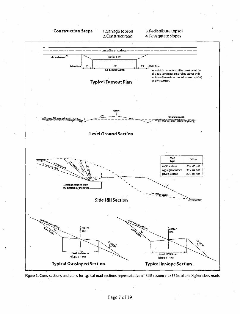
Construction Steps 1. Salvage topsoil 2. Construct road
3. Redistribute topsoil 4. Revegefate slopes
- center line of roadway -
shoulder—• turnout Iff
transition 25' 100* 25* : transition full turnout width
Typical Turnout Plan
Intervisibfe turnouts shall be constructed on al! single lane roads on all blind curves with additional twiouis as needed to keep spacing below 1000feet
Level Ground Section
. road type
crown
earth surface aggregate surface pcwed surface
m-mit/fi
0 2 - M ft/ft
JD2-JD3 ft / f t
Oapth measured from the bottom of the ditch.
Side Hill Section
. trawl surface - -(slope 2 -4%)
Typical Outsloped Section
(slope .2-4%)
Typical Inslope Section
Figure 1. Cross-sections and plans for typical road sections representative of BLM resource or FS local and higher-class roads.
Page 7 of 19

VII. DRILLING
A. DRILLING OPERATIONS REQUIREMENTS
The BLM is to be notified in advance for a representative to witness:
a. Spudding well (minimum of 24 hours) b. Setting and/or Cementing of all casing strings (minimum of 4 hours) c. BOPE tests (minimum of 4 hours)
IEI Eddy County Call the Carlsbad Field Office, 620 East Greene St., Carlsbad, NM 88220, (575) 361-2822
1. Although Hydrogen Sulfide has not been reported in the area, it is always a potential hazard. If Hydrogen Sulfide is encountered, report measured amounts and formations to the BLM.
2. Unless the production casing has been run and cemented or the well has been properly plugged, the drilling rig shall not be removed from over the hole without prior approval. If the drilling rig is removed without approval - an Incident of Non-Compliance will be written and will be a "Major" violation.
3. Floor controls are required for 3M or Greater systems. These controls will be on the rig floor, unobstructed, readily accessible to the driller and will be operational at all times during drilling and/or completion activities. Rig floor is defined as the area immediately around the rotary table; the area immediately above the substructure on which the draw works is located, this does not include the dog house or stairway area.
4. The record of the drilling rate along with the GR/N well log run from TD to surface (horizontal well - vertical portion of hole) shall be submitted to the BLM office as well as all other logs run on the borehole 30 days from completion. If available, a digital copy of the logs is to be submitted in addition to the paper copies. The top and bottom of Salt are to be recorded on the Completion Report.
B. CASING
Changes to the approved APD casing program need prior approval if the items substituted are of lesser grade or different casing size or are Non-API. The Operator can exchange the components of the proposal with that of superior strength (i.e. changing from J-55 to N-80, or from 36# to 40#). Changes to the approved cement program need prior approval if the altered cement plan has less volume or strength or if the changes are substantial (i.e. Multistage tool, ECP, etc.).
Page 8 of 19 \
The initial wellhead installed on the well will remain on the well with spools used as needed.
Centralizers required on surface casing per Onshore Order 2.III.B.l.f.
Wait on cement (WOC) time prior to drilling out for a primary cement job will be a minimum 18 hours for a water basin, 24 hours in the potash area, or 500 pounds compressive strength, whichever is greater for all casing strings. DURING THIS WOC TIME, NO DRILL PIPE, ETC. SHALL BE RUN IN THE HOLE. Provide compressive strengths including hours to reach required 500 pounds compressive strength prior to cementing each casing string. IF OPERATOR DOES NOT HAVE THE WELL SPECIFIC CEMENT DETAILS ONSITE PRIOR TO PUMPING THE CEMENT FOR EACH CASING STRING, THE WOC WILL BE 30 HOURS. See individual casing strings for details regarding lead cement slurry requirements.
No pea gravel permitted for remedial or fall back remedial without prior authorization from the BLM engineer.
Medium Cave/Karst Possibility of water flows in the Salado and Castile. Possibility of lost circulation in the Salado and Delaware.
1. The 13-3/8 inch surface casing shall be set at approximately 400 feet and cemented to the surface. If salt is encountered, set casing at least 25 feet above the salt. Excess calculates to 20% - Additional cement may be required.
a. If cement does not circulate to the surface, the appropriate BLM office shall be notified and a temperature survey utilizing an electronic type temperature survey with surface log readout will be used or a cement bond log shall be run to verify the top of the cement. Temperature survey will be run a minimum of six hours after pumping cement and ideally between 8-10 hours after completing the cement job..
b. Wait on cement (WOC) time for a primary cement job is to include the lead cement slurry.
c. Wait on cement (WOC) time for a remedial job will be a minimum of 4 hours after bringing cement to surface or 500 pounds compressive strength, whichever is greater.
d. If cement falls back, remedial cementing will be done prior to drilling out that string.
Page 9 of 19

2. The minimum required fi l l of cement behind the 9-5/8 inch intermediate casing is:
3 Cement to surface. If cement does not circulate see B.l.a, c-d above. Wait on cement (WOC) time for a primary cement job is to include the lead cement slurry due to cave/karst.
If 75% or greater lost circulation occurs while drilling the intermediate casing hole, the cement on the production casing must come to surface.
Centralizers required through the curve and a minimum of one every other joint.
3. The minimum required fill of cement behind the 7 inch production casing is:
^1 Cement should tie-back at least 200 feet into previous casing string. Operator shall provide method of verification.
4. Cement not required on the 4-1/2" casing. Packer system being used.
5. If hardband drill pipe is rotated inside casing, returns will be monitored for metal. If metal is found in samples, drill pipe will be pulled and rubber protectors which have a larger diameter than the tool joints of the drill pipe will be installed prior to continuing drilling operations.
C. PRESSURE CONTROL
1. All blowout preventer (BOP) and related equipment (BOPE) shall comply with well control requirements as described in Onshore Oil and Gas Order No. 2 and API RP 53 Sec. 17.
2. Minimum working pressure of the blowout preventer (BOP) and related equipment (BOPE) required for drilling below the surface casing shoe shall be 2000 (2M) psi (2M annular being used).
a. For surface casing only: If the BOP/BOPE is to be tested against casing, the wait on cement (WOC) time for that casing is to be met (see WOC statement at start of casing section). Independent service company required.
3. • Minimum working pressure of the blowout preventer (BOP) and related equipment (BOPE) required for drilling below the 9-5/8 intermediate casing shoe shall be 3000 (3M) psi.
Page 10 of 19

4. The appropriate BLM office shall be notified a minimum of 4 hours in advance for a representative to witness the tests.
a. In a water basin, for all casing strings utilizing slips, these are to be set as soon as the crew and rig are ready and any fallback cement remediation has been done. The casing cut-off and BOP installation can be initiated four hours after installing the slips, which will be approximately six hours after bumping the plug. For those casing strings not using slips, the minimum wait time before cut-off is eight hours after bumping the plug. BOP/BOPE testing can begin after cut-off or once cement reaches 500 psi compressive strength (including lead when specified), whichever is greater. However, i f the float does not hold, cut-off cannot be initiated until cement reaches 500 psi compressive strength (including lead when specified).
b. The tests shall be done by an independent service company utilizing a test plug not a cup or J-packer. The operator also has the option of utilizing an independent tester to test without a plug (i.e. against the casing) pursuant to Onshore Order 2 with the pressure not to exceed 70% of the burst rating for the. casing. Any test against the casing must meet the WOC time for water basin (18 hours) or potash (24 hours) or 500 pounds compressive strength, whichever is greater, prior to initiating the test (see casing segment as lead cement may be critical item).
(
c. The test shall be run on a 5000 psi chart for a 2-3M BOP/BOP, on a 10000 psi chart for a 5M BOP/BOPE and on a 15000 psi chart for a 10M BOP/BOPE. If a linear chart is used, it shall be a one hour chart. A circular chart shall have a maximum 2 hour clock. If a twelve hour or twenty-four hour chart is used, tester shall make a notation that it is run. with a two hour clock.
d. The results of the test shall be reported to the appropriate BLM office.
e. All tests are required to be recorded on a calibrated test chart. A copy of the BOP/BOPE test chart and a copy of independent service company test will be submitted to the appropriate BLM office.
f. The BOP/BOPE test shall include a low pressure test from 250 to 300 psi. The test will be held for a minimum of 10 minutes if test is done with a test plug and 30 minutes without a test plug. This test shall be performed prior to the test at full stack pressure.
D. DRILL STEM TEST
If drill stem tests are performed, Onshore Order 2.III.D shall be followed.
Page 11 of 19
E. WASTE MATERIAL AND FLUIDS
All waste (i.e. drilling fluids, trash, salts, chemicals, sewage, gray water, etc.) created as a result of drilling operations and completion operations shall be safely contained and disposed of properly at a waste disposal facility. No waste material or fluid shall be disposed of on the well location or surrounding area.
Porto-johns and trash containers will be on-location during fracturing operations or any other crew-intensive operations.
JAM 101714 \
<
Page 12 of 19

VIII. PRODUCTION (POST DRILLING)
A. WELL STRUCTURES & FACILITIES
Placement of Production Facilities Production facilities should be placed on the well pad to allow for maximum interim recontouring and revegetation of the well location.
Exclosure Netting (Open-top Tanks) Immediately following active drilling or completion operations, the operator will take actions necessary to prevent wildlife and livestock access, including avian wildlife, to all open-topped tanks that contain or have the potential to contain salinity sufficient to cause harm to wildlife or livestock, hydrocarbons, or Resource Conservation and Recovery Act of 1976-exempt hazardous substances. At a minimum, the operator will net, screen, or cover open-topped tanks to exclude wildlife and livestock and prevent mortality. If the operator uses netting, the operator will cover and secure the open portion of the tank to prevent wildlife entry. The operator will net, screen, or cover the tanks until the operator removes the tanks from the location or the tanks no longer contain substances that could be harmful to wildlife or livestock. Use a maximum netting mesh size of 1 Vi inches. The netting must not be in contact with fluids and must not have holes or gaps.
Chemical and Fuel Secondary Containment and Exclosure Screening The operator will prevent all hazardous, poisonous, flammable, and toxic substances from coming into contact with soil and water. At a minimum, the operator will install and maintain an impervious secondary containment system for any tank or barrel containing hazardous, poisonous, flammable, or toxic substances sufficient to contain the contents of the tank or barrel and any drips, leaks, and anticipated precipitation. The operator will dispose of fluids within the containment system that do not meet applicable state or U. S: Environmental Protection Agency livestock water standards in accordance with state law; the operator must not drain the fluids to the soil or ground. The operator will design, construct, and maintain all secondary containment systems to prevent wildlife and livestock exposure to harmful substances. At a minimum, the operator will install effective wildlife and livestock exclosure systems such'as fencing, netting, expanded metal mesh, lids, and grate covers. Use a maximum netting mesh size of 1 Vi inches.
Open-Vent Exhaust Stack Exclosures The operator will construct, modify, equip, and maintain all open-vent exhaust stacks on production equipment to prevent birds and bats from entering, and to discourage perching, roosting, and nesting. {Recommended exclosure structures on open-vent exhaust stacks are in the shape of a cone.) Production equipment includes, but may not be limited to, tanks, heater-treaters, separators, dehydrators, flare stacks, in-line units, and compressor mufflers.
Containment Structures Proposed production facilities such as storage tanks and other vessels will have a secondary containment structure that is constructed to hold the capacity of 1.5 times the
Page 13 of 19
largest tank, plus freeboard to account for precipitation, unless more stringent protective requirements are deemed necessary.
Painting Requirement All above-ground structures including meter housing that are not subject to safety requirements shall be painted a flat non-reflective paint color, Shale Green from the BLM Standard Environmental Color Chart (CC-001: June 2008).
B. PIPELINES
STANDARD STIPULATIONS FOR SURFACE INSTALLED PIPELINES
A copy of the application (Grant, Sundry Notice, APD) and attachments, including stipulations, survey plat and/or map, will be on location during construction. BLM personnel may request to you a copy of your permit during construction to ensure compliance with all stipulations.
Holder agrees to comply with the following stipulations to the satisfaction of the Authorized Officer:
1. The holder shall indemnify the United States against any liability for damage to life or property arising from the occupancy or use of public lands under this grant.
2. The holder shall comply with all applicable Federal laws and regulations existing or hereafter enacted or promulgated. In any event, the holder shall comply with the Toxic Substances Control Act of 1976 as amended, 15 USC 2601 et seq. (1982) with regards to any toxic substances that are used, generated by or stored on the right-of-way or on facilities authorized under this right-of-way grant. (See 40 CFR, Part 702-799 and especially, provisions on polychlorihated biphenyls, 40 CFR 761.1-761.193.) Additionally, any release of toxic substances (leaks, spills, etc.) in excess of the reportable quantity established by 40 CFR, Part 117 shall be reported as required by the Comprehensive Environmental Response, Compensation, and Liability Act, section 102b. A copy Of any report required or requested by any Federal agency or State government as a result of a reportable release or spill of any toxic substances shall be furnished to the authorized officer concurrent with the filing of the reports to the involved Federal agency or State government.
3. The holder agrees to indemnify the United States against any liability arising from the release of any hazardous substance or hazardous waste (as these terms are defined in the Comprehensive Environmental Response, Compensation and Liability Act of 1980, 42 U.S.C. 9601, et seq. or the Resource Conservation and Recovery Act, 42 U.S.C. 6901, et seq.) on the Right-of-Way (unless the release or threatened release is wholly unrelated to activity of the Right-of-Way holder's activity on the.Right-of-Way), or resulting from the activity of the Right-of-Way holder on the Right-of-Way. This agreement applies without regard to whether a release is caused by the holder, its agent, or unrelated third parties.
Page 14 of 19

4. The holder shall be liable for damage or injury to the United States to the extent provided by 43 CFR Sec. 2883.1-4. The holder shall be held to a standard of strict liability for damage or injury to the United States resulting from pipe rupture, fire, or spills caused or substantially aggravated by any of the following within the right-of-way or pennit area:
a. Activities of the holder including, but not limited to construction, operation, maintenance, and termination of the facility.
b. Activities of other parties including, but not limited to: (1) Land clearing. (2) Earth-disturbing and earth-moving work. (3) Blasting. . • -(4) Vandalism and sabotage.
c. Acts of God.
The maximum limitation for such strict liability damages shall not exceed one million dollars ($1,000,000) for any one event, and any liability in excess of such amount shall be determined by the ordinary rules of negligence of the jurisdiction in which the damage or injury occurred.
This section shall not impose strict liability for damage or injury resulting primarily from an act of war or from the negligent acts or omissions of the United States.
5. If, during any phase of the construction, operation, maintenance, or termination of the pipeline, any oil, salt water, or other pollutant should be discharged from the pipeline system, impacting Federal lands, the control and total removal, disposal, and cleaning up of such oil, salt water, or other pollutant, wherever found, shall be the responsibility of the holder, regardless of fault. Upon failure of the holder to control, dispose of, or clean up such discharge on or affecting Federal lands, or to repair all damages resulting therefrom, on the Federal lands, the Authorized Officer may take such measures as he deems necessary to control and clean up the discharge and restore the area, including, where appropriate, the aquatic environment and fish and wildlife habitats, at the full expense of the holder. Such action by the Authorized Officer shall not relieve the holder of any responsibility as provided herein.
6. All construction and maintenance activity will be confined to the authorized right-of-way width of 20 feet. If the pipeline route follows an existing road or buried pipeline right-of-way, the surface pipeline must be installed no farther than 10 feet from the edge ofthe road or buried pipeline right-of-way. If existing surface pipelines prevent this distance, the proposed surface pipeline must be installed immediately adjacent to the outer surface pipeline. All construction and maintenance activity will be confined to existing roads or right-of-ways.
7. No blading or clearing of any vegetation will be allowed unless approved in writing by the Authorized Officer.
Page 15 of 19

8. The holder shall install the pipeline on the surface in such a manner that will minimize suspension of the pipeline across low areas in the terrain. In hummocky of duney areas, the pipeline will be "snaked" around hummocks and dunes rather then suspended across these features.
9. The pipeline shall be buried with a minimum of 24 inches under all roads, "two-tracks," and trails. Burial of the pipe will continue for 20 feet on each side of each crossing. The condition of the road, upon completion of construction, shall be returned to at least its former state With no bumps or dips remaining in the road surface.
10. The holder shall minimize disturbance to existing fences and other improvements on public lands. The holder is required to promptly repair improvements to at least their former state. Functional use of these improvements will be maintained at all times. The holder will contact the owner of any improvements prior to disturbing them. When necessary to pass through a fence line, the fence shall be braced on both sides of the passageway prior to cutting of the fence. No permanent gates will be allowed unless approved by the Authorized Officer.
11. In those areas where erosion control structures are required to stabilize soil conditions, the holder will install such structures as are suitable for the specific soil conditions being encountered and which are in accordance with sound resource management practices.
12. Excluding the pipe, all above-ground structures not subject to safety requirement shall be painted by the holder to blend with the natural color of the landscape. The paint used shall be a color which simulates "Standard Environmental Colors" - Shale Green, Munsell Soil Color No. 5Y 4/2; designated by the Rocky Mountain Five State Interagency Committee.
13. The pipeline will be identified by signs at the point of origin and completion of the . right-of-way and at all road crossings. At a minimum, signs will state the holder's name, BLM serial number, and the product being transported. Signs will be maintained in a legible condition for the life of the pipeline.
14. The holder shall not use the pipeline route as a road for purposes other than routine maintenance as determined necessary by the Authorized Officer in consultation with the holder. The holder will take whatever steps are necessary to ensure that the pipeline route is not used as a roadway.
15. Any cultural and/or paleontological resource (historic or prehistoric site or object) discovered by the holder, or any person working on his behalf, on public or Federal land shall be immediately reported to the authorized officer. Holder shall suspend all operations in the immediate area of such discovery until written authorization to proceed is issued by the authorized officer. An evaluation of the discovery will be made by the authorized officer to determine appropriate cultural or scientific values. The holder will be responsible for the cost of evaluation and any decision as to proper mitigation
Page 16 of 19

measures will be made by the authorized officer after consulting with the holder.
16. The operator shall be held responsible i f noxious weeds become established within the areas of operations. Weed control shall be required on the disturbed land where noxious weeds exist, which includes the roads, powerline corridor, and adjacent land affected by the establishment of weeds due to this action. The operator shall consult with the Authorized Officer for acceptable weed control methods, which include following EPA and BLM requirements and policies.
17. Surface pipelines must be less than or equal to 4 inches and a working pressure below 125 psi.
IX. INTERIM RECLAMATION
During the life of the development, all disturbed areas not needed for active support of production operations should undergo interim reclamation in order to minimize the environmental impacts of development on other resources and uses.
Within six (6) months of well completion, Operators should work with BLM surface management specialists (Jim Amos: 575-234-5909) to devise the best strategies to reduce the size of the location. Interim reclamation should allow for remedial well operations, as well as safe and efficient removal of oil and gas.
During reclamation, the removal of caliche is important to increasing the success of revegetating the site. Removed caliche that is free of contaminants may be used for road repairs, fire walls or for building other roads and locations. In order to operate the well or complete workover operations, it may be necessary to drive, park and operate on restored interim vegetation within the previously disturbed area. Disturbing revegetated areas for production or workover operations will be allowed. If there is significant disturbance and loss of vegetation, the area will need to be revegetated. Communicate with the appropriate BLM office for any exceptions/exemptions if needed.
All disturbed areas after they have been satisfactorily prepared need to be reseeded with the seed mixture provided below.
Upon completion of interim reclamation, the operator shall submit a Sundry Notices and Reports on Wells, Subsequent Report of Reclamation (Form 3160-5).
X. FINAL ABANDONMENT & RECLAMATION
At final abandonment, well locations, production facilities, and access roads must undergo "final" reclamation so that the character and productivity of the land are restored.
Earthwork for final reclamation must be completed within six (6) months of well plugging. All pads, pits, facility locations and roads must be reclaimed to a satisfactory
Page 17 of 19

revegetated, safe, and stable condition, unless an agreement is made with the landowner or BLM to keep the road and/or pad intact.
After all disturbed areas have been satisfactorily prepared, these areas need to be revegetated with the seed mixture provided below. Seeding should be accomplished by drilling on the contour whenever practical or by other approved methods. Seeding may need to be repeated until revegetation is successful, as determined by the BLM.
Operators shall contact a BLM surface protection specialist prior to surface abandonment operations for site specific objectives (Jim Amos: 575-234-5909).
Page 18 of 19

Seed Mixture 1, for Loamy Sites
The holder shall seed all disturbed areas with the seed mixture listed below. The seed mixture shall be planted in the amounts specified in pounds of pure live seed (PLS)* per acre. There shall be no primary or secondary noxious weeds in the seed mixture. Seed will be tested and the viability testing of seed will be done in accordance with State law(s) and within nine (9) months prior to purchase. Commercial seed will be either certified or registered seed. The seed container will be tagged in accordance with State law(s) and available for inspection by the authorized officer.
Seed will be planted using a drill equipped with a depth regulator to ensure proper depth regulator to ensure proper depth of planting where drilling is possible. The seed mixture will be evenly and uniformly planted over the disturbed area (small/heavier seeds have a tendency to drop the bottom of the drill and are planted first). The holder shall take appropriate measures to ensure this does not occur. Where drilling is not possible, seed will be broadcast and the area shall be raked or chained to cover the seed. When broadcasting the seed, the pounds per acre are to be doubled. The seeding will be repeated until a satisfactory stand is established as determined by the authorized officer. Evaluation of growth will not be made before completion of at least one full growing season after seeding.
Species to be planted in pounds of pure live seed* per acre:
Species lb/acre Plains lovegrass (Eragrostis intermedia) 0.5 Sand dropseed (Sporobolus cryptandrus) 1.0 Sideoats grama (Bouteloua curtipendula) 5.0 Plains bristlegrass (Setaria macrostachya) 2.0
Pounds of pure live seed:
Pounds of seed x percent purity x percent germination = pounds pure live seed
Page 19 of 19
>