WS 2000 Wireless Switch - Isis Integration Ltd · WS 2000 Wireless Switch System Reference Guide...
494
WS 2000 Wireless Switch System Reference
Transcript of WS 2000 Wireless Switch - Isis Integration Ltd · WS 2000 Wireless Switch System Reference Guide...
WS 2000 Wireless SwitchSystem Reference

Contents
Chapter 1. Product OverviewWS 2000 Wireless Switch System Reference Guide . . . . . . . . . . . . . . . . . . . . . . . . . . . . . . . . . . . . . . . . . . . . . 1-2
About this Document . . . . . . . . . . . . . . . . . . . . . . . . . . . . . . . . . . . . . . . . . . . . . . . . . . . . . . . . . . . . . . . . . . 1-2Document Conventions . . . . . . . . . . . . . . . . . . . . . . . . . . . . . . . . . . . . . . . . . . . . . . . . . . . . . . . . . . . . . . . . 1-2
System Overview . . . . . . . . . . . . . . . . . . . . . . . . . . . . . . . . . . . . . . . . . . . . . . . . . . . . . . . . . . . . . . . . . . . . . . . . . 1-3Management of Access Ports . . . . . . . . . . . . . . . . . . . . . . . . . . . . . . . . . . . . . . . . . . . . . . . . . . . . . . . . . . . 1-3
Hardware Overview . . . . . . . . . . . . . . . . . . . . . . . . . . . . . . . . . . . . . . . . . . . . . . . . . . . . . . . . . . . . . . . . . . . . . . . 1-4Technical Specifications . . . . . . . . . . . . . . . . . . . . . . . . . . . . . . . . . . . . . . . . . . . . . . . . . . . . . . . . . . . . . . . 1-4WS 2000 Wireless Switch LED Functions . . . . . . . . . . . . . . . . . . . . . . . . . . . . . . . . . . . . . . . . . . . . . . . . . . 1-5
Software Overview. . . . . . . . . . . . . . . . . . . . . . . . . . . . . . . . . . . . . . . . . . . . . . . . . . . . . . . . . . . . . . . . . . . . . . . . 1-6Operating System (OS) Services . . . . . . . . . . . . . . . . . . . . . . . . . . . . . . . . . . . . . . . . . . . . . . . . . . . . . . . . . 1-6Cell Controller Services . . . . . . . . . . . . . . . . . . . . . . . . . . . . . . . . . . . . . . . . . . . . . . . . . . . . . . . . . . . . . . . . 1-6Gateway Services . . . . . . . . . . . . . . . . . . . . . . . . . . . . . . . . . . . . . . . . . . . . . . . . . . . . . . . . . . . . . . . . . . . . 1-6
Chapter 2. Getting StartedGetting Started with the WS 2000 Wireless Switch. . . . . . . . . . . . . . . . . . . . . . . . . . . . . . . . . . . . . . . . . . . . . . 2-2
Enable Subnet1 . . . . . . . . . . . . . . . . . . . . . . . . . . . . . . . . . . . . . . . . . . . . . . . . . . . . . . . . . . . . . . . . . . . . . . 2-5Communicating with the Outside World . . . . . . . . . . . . . . . . . . . . . . . . . . . . . . . . . . . . . . . . . . . . . . . . . . . 2-7Setting Up Point-to-Point over Ethernet (PPPoE) Communication . . . . . . . . . . . . . . . . . . . . . . . . . . . . . . . . 2-8Wireless Summary Area . . . . . . . . . . . . . . . . . . . . . . . . . . . . . . . . . . . . . . . . . . . . . . . . . . . . . . . . . . . . . . . 2-9Setting the Authentication Method . . . . . . . . . . . . . . . . . . . . . . . . . . . . . . . . . . . . . . . . . . . . . . . . . . . . . . 2-10Setting the Encryption Method . . . . . . . . . . . . . . . . . . . . . . . . . . . . . . . . . . . . . . . . . . . . . . . . . . . . . . . . . 2-10Mobile Unit Access Control List (ACL) . . . . . . . . . . . . . . . . . . . . . . . . . . . . . . . . . . . . . . . . . . . . . . . . . . . . 2-11
Where to Go from Here? . . . . . . . . . . . . . . . . . . . . . . . . . . . . . . . . . . . . . . . . . . . . . . . . . . . . . . . . . . . . . . . . . . 2-12
WS 2000 Wireless Switch System Reference GuideTOC-2
Chapter 3. LAN/Subnet ConfigurationEnabling Subnets for the LAN Interface. . . . . . . . . . . . . . . . . . . . . . . . . . . . . . . . . . . . . . . . . . . . . . . . . . . . . . . .3-2
Defining Subnets . . . . . . . . . . . . . . . . . . . . . . . . . . . . . . . . . . . . . . . . . . . . . . . . . . . . . . . . . . . . . . . . . . . . .3-2Configuring Subnets . . . . . . . . . . . . . . . . . . . . . . . . . . . . . . . . . . . . . . . . . . . . . . . . . . . . . . . . . . . . . . . . . . . . . . .3-3
The DHCP Configuration. . . . . . . . . . . . . . . . . . . . . . . . . . . . . . . . . . . . . . . . . . . . . . . . . . . . . . . . . . . . . . . .3-4Advanced DHCP Settings . . . . . . . . . . . . . . . . . . . . . . . . . . . . . . . . . . . . . . . . . . . . . . . . . . . . . . . . . . . . . . .3-5
Configuring Subnet Access. . . . . . . . . . . . . . . . . . . . . . . . . . . . . . . . . . . . . . . . . . . . . . . . . . . . . . . . . . . . . . . . . .3-5The Access Overview Table . . . . . . . . . . . . . . . . . . . . . . . . . . . . . . . . . . . . . . . . . . . . . . . . . . . . . . . . . . . . .3-6The Access Exception Area . . . . . . . . . . . . . . . . . . . . . . . . . . . . . . . . . . . . . . . . . . . . . . . . . . . . . . . . . . . . .3-6
Advanced Subnet Access Settings. . . . . . . . . . . . . . . . . . . . . . . . . . . . . . . . . . . . . . . . . . . . . . . . . . . . . . . . . . . .3-8Virtual LAN (VLAN) Configuration . . . . . . . . . . . . . . . . . . . . . . . . . . . . . . . . . . . . . . . . . . . . . . . . . . . . . . . . . . .3-11
Chapter 4. WAN ConfigurationConfiguring the WAN Interface . . . . . . . . . . . . . . . . . . . . . . . . . . . . . . . . . . . . . . . . . . . . . . . . . . . . . . . . . . . . . .4-2
Communicating with the Outside World . . . . . . . . . . . . . . . . . . . . . . . . . . . . . . . . . . . . . . . . . . . . . . . . . . .4-2Setting Up Point-to-Point over Ethernet (PPPoE) Communication . . . . . . . . . . . . . . . . . . . . . . . . . . . . . . . .4-3
Configuring the WS 2000 Firewall . . . . . . . . . . . . . . . . . . . . . . . . . . . . . . . . . . . . . . . . . . . . . . . . . . . . . . . . . . . .4-4Disabling the Firewall. . . . . . . . . . . . . . . . . . . . . . . . . . . . . . . . . . . . . . . . . . . . . . . . . . . . . . . . . . . . . . . . . .4-4Setting the NAT Timeout . . . . . . . . . . . . . . . . . . . . . . . . . . . . . . . . . . . . . . . . . . . . . . . . . . . . . . . . . . . . . . .4-4Configurable Firewall Filters . . . . . . . . . . . . . . . . . . . . . . . . . . . . . . . . . . . . . . . . . . . . . . . . . . . . . . . . . . . .4-4
Configuring Content Filtering . . . . . . . . . . . . . . . . . . . . . . . . . . . . . . . . . . . . . . . . . . . . . . . . . . . . . . . . . . . . . . . .4-6Configuring Network Address Translation (NAT). . . . . . . . . . . . . . . . . . . . . . . . . . . . . . . . . . . . . . . . . . . . . . . . .4-7
Configuring Static Routes. . . . . . . . . . . . . . . . . . . . . . . . . . . . . . . . . . . . . . . . . . . . . . . . . . . . . . . . . . . . . . . . . .4-10Creating User-Defined Routes . . . . . . . . . . . . . . . . . . . . . . . . . . . . . . . . . . . . . . . . . . . . . . . . . . . . . . . . . .4-10Setting the RIP Configuration. . . . . . . . . . . . . . . . . . . . . . . . . . . . . . . . . . . . . . . . . . . . . . . . . . . . . . . . . . .4-11
Configuring a Virtual Private Network (VPN) . . . . . . . . . . . . . . . . . . . . . . . . . . . . . . . . . . . . . . . . . . . . . . . . . . .4-12Creating a VPN Tunnel . . . . . . . . . . . . . . . . . . . . . . . . . . . . . . . . . . . . . . . . . . . . . . . . . . . . . . . . . . . . . . .4-14Setting Up VPN Security. . . . . . . . . . . . . . . . . . . . . . . . . . . . . . . . . . . . . . . . . . . . . . . . . . . . . . . . . . . . . . .4-14Configuring Manual Key Exchange . . . . . . . . . . . . . . . . . . . . . . . . . . . . . . . . . . . . . . . . . . . . . . . . . . . . . .4-15Setting Up Automatic Key Exchange . . . . . . . . . . . . . . . . . . . . . . . . . . . . . . . . . . . . . . . . . . . . . . . . . . . . .4-17Setting Up Internet Key Exchange (IKE) . . . . . . . . . . . . . . . . . . . . . . . . . . . . . . . . . . . . . . . . . . . . . . . . . .4-18VPN: Frequently Asked Questions . . . . . . . . . . . . . . . . . . . . . . . . . . . . . . . . . . . . . . . . . . . . . . . . . . . . . . .4-20
Chapter 5. Wireless ConfigurationEnabling Wireless LANs (WLANs) . . . . . . . . . . . . . . . . . . . . . . . . . . . . . . . . . . . . . . . . . . . . . . . . . . . . . . . . . . . .5-3
Wireless Summary Area. . . . . . . . . . . . . . . . . . . . . . . . . . . . . . . . . . . . . . . . . . . . . . . . . . . . . . . . . . . . . . . .5-3Access Port Adoption . . . . . . . . . . . . . . . . . . . . . . . . . . . . . . . . . . . . . . . . . . . . . . . . . . . . . . . . . . . . . . . . . .5-4
Configuring Wireless LANs . . . . . . . . . . . . . . . . . . . . . . . . . . . . . . . . . . . . . . . . . . . . . . . . . . . . . . . . . . . . . . . . .5-5Configuring Wireless LAN Security . . . . . . . . . . . . . . . . . . . . . . . . . . . . . . . . . . . . . . . . . . . . . . . . . . . . . . . . . . .5-6
Selecting the Authentication Method . . . . . . . . . . . . . . . . . . . . . . . . . . . . . . . . . . . . . . . . . . . . . . . . . . . . .5-6Configuring 802.1x EAP Authentication . . . . . . . . . . . . . . . . . . . . . . . . . . . . . . . . . . . . . . . . . . . . . . . . . . . .5-7Configuring Kerberos Authentication. . . . . . . . . . . . . . . . . . . . . . . . . . . . . . . . . . . . . . . . . . . . . . . . . . . . . .5-8Setting the Encryption Method . . . . . . . . . . . . . . . . . . . . . . . . . . . . . . . . . . . . . . . . . . . . . . . . . . . . . . . . . .5-9Configuring WEP Encryption . . . . . . . . . . . . . . . . . . . . . . . . . . . . . . . . . . . . . . . . . . . . . . . . . . . . . . . . . . . .5-9Configuring WPA-TKIP Encryption . . . . . . . . . . . . . . . . . . . . . . . . . . . . . . . . . . . . . . . . . . . . . . . . . . . . . . .5-10Configuring WPA2-CCMP (802.11i) Encryption . . . . . . . . . . . . . . . . . . . . . . . . . . . . . . . . . . . . . . . . . . . . .5-11KeyGuard . . . . . . . . . . . . . . . . . . . . . . . . . . . . . . . . . . . . . . . . . . . . . . . . . . . . . . . . . . . . . . . . . . . . . . . . . .5-12
TOC-3
No Encryption . . . . . . . . . . . . . . . . . . . . . . . . . . . . . . . . . . . . . . . . . . . . . . . . . . . . . . . . . . . . . . . . . . . . . .5-12Mobile Unit Access Control List (ACL) . . . . . . . . . . . . . . . . . . . . . . . . . . . . . . . . . . . . . . . . . . . . . . . . . . .5-13
Configuring Access Ports . . . . . . . . . . . . . . . . . . . . . . . . . . . . . . . . . . . . . . . . . . . . . . . . . . . . . . . . . . . . . . . . . .5-13Setting Default Access Port Settings. . . . . . . . . . . . . . . . . . . . . . . . . . . . . . . . . . . . . . . . . . . . . . . . . . . . . . . . .5-16
Common Settings to All Radio Types . . . . . . . . . . . . . . . . . . . . . . . . . . . . . . . . . . . . . . . . . . . . . . . . . . . .5-16Radio-Specific Settings . . . . . . . . . . . . . . . . . . . . . . . . . . . . . . . . . . . . . . . . . . . . . . . . . . . . . . . . . . . . . . .5-19
Advanced Access Port Settings . . . . . . . . . . . . . . . . . . . . . . . . . . . . . . . . . . . . . . . . . . . . . . . . . . . . . . . . . . . . .5-19Radio Settings . . . . . . . . . . . . . . . . . . . . . . . . . . . . . . . . . . . . . . . . . . . . . . . . . . . . . . . . . . . . . . . . . . . . . .5-20Antenna Settings . . . . . . . . . . . . . . . . . . . . . . . . . . . . . . . . . . . . . . . . . . . . . . . . . . . . . . . . . . . . . . . . . . . .5-21Advanced Properties . . . . . . . . . . . . . . . . . . . . . . . . . . . . . . . . . . . . . . . . . . . . . . . . . . . . . . . . . . . . . . . . .5-21
Quality of Service Configuration . . . . . . . . . . . . . . . . . . . . . . . . . . . . . . . . . . . . . . . . . . . . . . . . . . . . . . . . . . . .5-22Setting the Bandwidth Share Mode. . . . . . . . . . . . . . . . . . . . . . . . . . . . . . . . . . . . . . . . . . . . . . . . . . . . . .5-23Configuring Voice Prioritization and Multicast Address Settings . . . . . . . . . . . . . . . . . . . . . . . . . . . . . . .5-24
Setting Up Port Authentication for AP 300 Access Ports. . . . . . . . . . . . . . . . . . . . . . . . . . . . . . . . . . . . . . . . . .5-24Rogue Access Point (Port) Detection . . . . . . . . . . . . . . . . . . . . . . . . . . . . . . . . . . . . . . . . . . . . . . . . . . . . . . . . .5-25
Setting Up the Detection Method . . . . . . . . . . . . . . . . . . . . . . . . . . . . . . . . . . . . . . . . . . . . . . . . . . . . . . .5-26Defining and Maintaining Approved AP List Rules . . . . . . . . . . . . . . . . . . . . . . . . . . . . . . . . . . . . . . . . . .5-27Examine the Approve and Rogue Access Ports . . . . . . . . . . . . . . . . . . . . . . . . . . . . . . . . . . . . . . . . . . . . .5-27Setting SNMP Traps for Rogue APs. . . . . . . . . . . . . . . . . . . . . . . . . . . . . . . . . . . . . . . . . . . . . . . . . . . . . .5-30
Chapter 6. Administrator and User AccessConfiguring Administrator Access . . . . . . . . . . . . . . . . . . . . . . . . . . . . . . . . . . . . . . . . . . . . . . . . . . . . . . . . . . . .6-2
Selecting the Type of Admin Access . . . . . . . . . . . . . . . . . . . . . . . . . . . . . . . . . . . . . . . . . . . . . . . . . . . . . .6-2Configuring Secure Shell Connection Parameters . . . . . . . . . . . . . . . . . . . . . . . . . . . . . . . . . . . . . . . . . . . .6-3Admin Authentication and RADIUS Server Authentication Setup . . . . . . . . . . . . . . . . . . . . . . . . . . . . . . .6-3Setting Up AirBEAM Software Access . . . . . . . . . . . . . . . . . . . . . . . . . . . . . . . . . . . . . . . . . . . . . . . . . . . .6-3Applet Timeout Specification. . . . . . . . . . . . . . . . . . . . . . . . . . . . . . . . . . . . . . . . . . . . . . . . . . . . . . . . . . . .6-3Changing the Administrator Password. . . . . . . . . . . . . . . . . . . . . . . . . . . . . . . . . . . . . . . . . . . . . . . . . . . . .6-4
Configuring User Authentication . . . . . . . . . . . . . . . . . . . . . . . . . . . . . . . . . . . . . . . . . . . . . . . . . . . . . . . . . . . . .6-4Configuring the RADIUS Server . . . . . . . . . . . . . . . . . . . . . . . . . . . . . . . . . . . . . . . . . . . . . . . . . . . . . . . . . .6-5Configuring Lightweight Directory Access Protocol (LDAP) Authentication . . . . . . . . . . . . . . . . . . . . . . . .6-6Setting Up a Proxy RADIUS Server. . . . . . . . . . . . . . . . . . . . . . . . . . . . . . . . . . . . . . . . . . . . . . . . . . . . . . . .6-7Managing the Local User Database. . . . . . . . . . . . . . . . . . . . . . . . . . . . . . . . . . . . . . . . . . . . . . . . . . . . . . .6-8Setting the User Access Policy. . . . . . . . . . . . . . . . . . . . . . . . . . . . . . . . . . . . . . . . . . . . . . . . . . . . . . . . . .6-10
Managing Digital Certificates . . . . . . . . . . . . . . . . . . . . . . . . . . . . . . . . . . . . . . . . . . . . . . . . . . . . . . . . . . . . . .6-11Importing CA Certificates . . . . . . . . . . . . . . . . . . . . . . . . . . . . . . . . . . . . . . . . . . . . . . . . . . . . . . . . . . . . . .6-11Creating Self Certificates . . . . . . . . . . . . . . . . . . . . . . . . . . . . . . . . . . . . . . . . . . . . . . . . . . . . . . . . . . . . . .6-12
Chapter 7. Switch AdministrationOverview of Administration Support . . . . . . . . . . . . . . . . . . . . . . . . . . . . . . . . . . . . . . . . . . . . . . . . . . . . . . . . . .7-3Restarting the WS 2000 Wireless Switch . . . . . . . . . . . . . . . . . . . . . . . . . . . . . . . . . . . . . . . . . . . . . . . . . . . . . .7-3Changing the Name of the Switch . . . . . . . . . . . . . . . . . . . . . . . . . . . . . . . . . . . . . . . . . . . . . . . . . . . . . . . . . . . .7-4Changing the Location and Country Settings of the WS 2000 . . . . . . . . . . . . . . . . . . . . . . . . . . . . . . . . . . . . . .7-4Configuring Switch Redundancy . . . . . . . . . . . . . . . . . . . . . . . . . . . . . . . . . . . . . . . . . . . . . . . . . . . . . . . . . . . . .7-6
Setting Up Switch Redundancy . . . . . . . . . . . . . . . . . . . . . . . . . . . . . . . . . . . . . . . . . . . . . . . . . . . . . . . . . .7-6Redundancy Operations Status . . . . . . . . . . . . . . . . . . . . . . . . . . . . . . . . . . . . . . . . . . . . . . . . . . . . . . . . . .7-7
Updating the WS 2000 Wireless Switch’s Firmware . . . . . . . . . . . . . . . . . . . . . . . . . . . . . . . . . . . . . . . . . . . . .7-7Checking for and Downloading Firmware Updates . . . . . . . . . . . . . . . . . . . . . . . . . . . . . . . . . . . . . . . . . . .7-7
WS 2000 Wireless Switch System Reference GuideTOC-4
Performing the Firmware Update . . . . . . . . . . . . . . . . . . . . . . . . . . . . . . . . . . . . . . . . . . . . . . . . . . . . . . . . .7-8Setting Up DHCP Options for Firmware Upload. . . . . . . . . . . . . . . . . . . . . . . . . . . . . . . . . . . . . . . . . . . . . .7-8
Exporting and Importing Wireless Switch Settings . . . . . . . . . . . . . . . . . . . . . . . . . . . . . . . . . . . . . . . . . . . . . . .7-9To Import or Export Settings to an FTP or TFTP Site . . . . . . . . . . . . . . . . . . . . . . . . . . . . . . . . . . . . . . . . .7-10To Import Settings to a Local File. . . . . . . . . . . . . . . . . . . . . . . . . . . . . . . . . . . . . . . . . . . . . . . . . . . . . . . .7-11To Export Settings to a Local File . . . . . . . . . . . . . . . . . . . . . . . . . . . . . . . . . . . . . . . . . . . . . . . . . . . . . . . .7-11Sample Configuration File . . . . . . . . . . . . . . . . . . . . . . . . . . . . . . . . . . . . . . . . . . . . . . . . . . . . . . . . . . . . .7-11
Configuring SNMP . . . . . . . . . . . . . . . . . . . . . . . . . . . . . . . . . . . . . . . . . . . . . . . . . . . . . . . . . . . . . . . . . . . . . . .7-19Setting the SNMP Version Configuration . . . . . . . . . . . . . . . . . . . . . . . . . . . . . . . . . . . . . . . . . . . . . . . . .7-20Setting Up the Access Control List. . . . . . . . . . . . . . . . . . . . . . . . . . . . . . . . . . . . . . . . . . . . . . . . . . . . . . .7-21Setting the Trap Configuration . . . . . . . . . . . . . . . . . . . . . . . . . . . . . . . . . . . . . . . . . . . . . . . . . . . . . . . . .7-22Setting the Trap Configuration for SNMP v1/v2c . . . . . . . . . . . . . . . . . . . . . . . . . . . . . . . . . . . . . . . . . . .7-22Setting the Trap Configuration for SNMP V3. . . . . . . . . . . . . . . . . . . . . . . . . . . . . . . . . . . . . . . . . . . . . . .7-23Selecting Traps. . . . . . . . . . . . . . . . . . . . . . . . . . . . . . . . . . . . . . . . . . . . . . . . . . . . . . . . . . . . . . . . . . . . . .7-23Setting Rate Traps . . . . . . . . . . . . . . . . . . . . . . . . . . . . . . . . . . . . . . . . . . . . . . . . . . . . . . . . . . . . . . . . . . .7-26
Specifying a Network Time Protocol (NTP) Server. . . . . . . . . . . . . . . . . . . . . . . . . . . . . . . . . . . . . . . . . . . . . . .7-27Setting Up and Viewing the System Log . . . . . . . . . . . . . . . . . . . . . . . . . . . . . . . . . . . . . . . . . . . . . . . . . . . . . .7-28
Viewing the Log on the Switch . . . . . . . . . . . . . . . . . . . . . . . . . . . . . . . . . . . . . . . . . . . . . . . . . . . . . . . . .7-28Setting Up a Log Server . . . . . . . . . . . . . . . . . . . . . . . . . . . . . . . . . . . . . . . . . . . . . . . . . . . . . . . . . . . . . . .7-29
Chapter 8. Status & StatisticsWAN Statistics . . . . . . . . . . . . . . . . . . . . . . . . . . . . . . . . . . . . . . . . . . . . . . . . . . . . . . . . . . . . . . . . . . . . . . . . . . .8-2Subnet Statistics. . . . . . . . . . . . . . . . . . . . . . . . . . . . . . . . . . . . . . . . . . . . . . . . . . . . . . . . . . . . . . . . . . . . . . . . . .8-3
Interfaces . . . . . . . . . . . . . . . . . . . . . . . . . . . . . . . . . . . . . . . . . . . . . . . . . . . . . . . . . . . . . . . . . . . . . . . . . . .8-5
Wireless LAN Statistics . . . . . . . . . . . . . . . . . . . . . . . . . . . . . . . . . . . . . . . . . . . . . . . . . . . . . . . . . . . . . . . . . . . .8-6Displaying WLAN Summary Information . . . . . . . . . . . . . . . . . . . . . . . . . . . . . . . . . . . . . . . . . . . . . . . . . . .8-6Getting Statistics for a Particular WLAN . . . . . . . . . . . . . . . . . . . . . . . . . . . . . . . . . . . . . . . . . . . . . . . . . . .8-7General WLAN Information . . . . . . . . . . . . . . . . . . . . . . . . . . . . . . . . . . . . . . . . . . . . . . . . . . . . . . . . . . . . .8-8
Access Port Statistics . . . . . . . . . . . . . . . . . . . . . . . . . . . . . . . . . . . . . . . . . . . . . . . . . . . . . . . . . . . . . . . . . . . . . .8-9Access Port Statistics Summary Screen . . . . . . . . . . . . . . . . . . . . . . . . . . . . . . . . . . . . . . . . . . . . . . . . . . .8-9Detailed Information About a Particular Access Port . . . . . . . . . . . . . . . . . . . . . . . . . . . . . . . . . . . . . . . .8-10General Access Port Information . . . . . . . . . . . . . . . . . . . . . . . . . . . . . . . . . . . . . . . . . . . . . . . . . . . . . . . .8-11
Mobile Unit (MU) Statistics . . . . . . . . . . . . . . . . . . . . . . . . . . . . . . . . . . . . . . . . . . . . . . . . . . . . . . . . . . . . . . . .8-13View Statistics in Graphic Form . . . . . . . . . . . . . . . . . . . . . . . . . . . . . . . . . . . . . . . . . . . . . . . . . . . . . . . . . . . . .8-14
Chapter 9. WS 2000 Use CasesRetail Use Case. . . . . . . . . . . . . . . . . . . . . . . . . . . . . . . . . . . . . . . . . . . . . . . . . . . . . . . . . . . . . . . . . . . . . . . . . . .9-3
A Retail Example . . . . . . . . . . . . . . . . . . . . . . . . . . . . . . . . . . . . . . . . . . . . . . . . . . . . . . . . . . . . . . . . . . . . .9-3The Plan . . . . . . . . . . . . . . . . . . . . . . . . . . . . . . . . . . . . . . . . . . . . . . . . . . . . . . . . . . . . . . . . . . . . . . . . . . . . . . . .9-3Contacting the Wireless Switch. . . . . . . . . . . . . . . . . . . . . . . . . . . . . . . . . . . . . . . . . . . . . . . . . . . . . . . . . . . . . .9-4
Entering the Basic System Settings . . . . . . . . . . . . . . . . . . . . . . . . . . . . . . . . . . . . . . . . . . . . . . . . . . . . . . .9-5Setting Access Control . . . . . . . . . . . . . . . . . . . . . . . . . . . . . . . . . . . . . . . . . . . . . . . . . . . . . . . . . . . . . . . . .9-6The IP Address Plan . . . . . . . . . . . . . . . . . . . . . . . . . . . . . . . . . . . . . . . . . . . . . . . . . . . . . . . . . . . . . . . . . . .9-7
Configuring POS Subnet . . . . . . . . . . . . . . . . . . . . . . . . . . . . . . . . . . . . . . . . . . . . . . . . . . . . . . . . . . . . . . . . . . . .9-8Configuring the Printer Subnet . . . . . . . . . . . . . . . . . . . . . . . . . . . . . . . . . . . . . . . . . . . . . . . . . . . . . . . . . . . . . . .9-9Configuring the Cafe Subnet . . . . . . . . . . . . . . . . . . . . . . . . . . . . . . . . . . . . . . . . . . . . . . . . . . . . . . . . . . . . . . .9-11Configuring the WAN Interface . . . . . . . . . . . . . . . . . . . . . . . . . . . . . . . . . . . . . . . . . . . . . . . . . . . . . . . . . . . . .9-13Configuring Network Address Translation (NAT). . . . . . . . . . . . . . . . . . . . . . . . . . . . . . . . . . . . . . . . . . . . . . . .9-14
TOC-5
Inspecting the Firewall . . . . . . . . . . . . . . . . . . . . . . . . . . . . . . . . . . . . . . . . . . . . . . . . . . . . . . . . . . . . . . . . . . . .9-16Configuring the Access Ports . . . . . . . . . . . . . . . . . . . . . . . . . . . . . . . . . . . . . . . . . . . . . . . . . . . . . . . . . . . . . . .9-16
Setting Access Port Defaults . . . . . . . . . . . . . . . . . . . . . . . . . . . . . . . . . . . . . . . . . . . . . . . . . . . . . . . . . . .9-17Naming the POS Access Port . . . . . . . . . . . . . . . . . . . . . . . . . . . . . . . . . . . . . . . . . . . . . . . . . . . . . . . . . . .9-18Configuring the Printer Access Port . . . . . . . . . . . . . . . . . . . . . . . . . . . . . . . . . . . . . . . . . . . . . . . . . . . . . .9-19Configuring the Cafe Access Port. . . . . . . . . . . . . . . . . . . . . . . . . . . . . . . . . . . . . . . . . . . . . . . . . . . . . . . .9-20Associating the Access Ports to the WLANs . . . . . . . . . . . . . . . . . . . . . . . . . . . . . . . . . . . . . . . . . . . . . . .9-21
Configuring the Cafe WLAN. . . . . . . . . . . . . . . . . . . . . . . . . . . . . . . . . . . . . . . . . . . . . . . . . . . . . . . . . . . . . . . .9-22Configuring the Printer WLAN . . . . . . . . . . . . . . . . . . . . . . . . . . . . . . . . . . . . . . . . . . . . . . . . . . . . . . . . . . . . . .9-24Configuring the POS WLAN . . . . . . . . . . . . . . . . . . . . . . . . . . . . . . . . . . . . . . . . . . . . . . . . . . . . . . . . . . . . . . . .9-26Configuring Subnet Access . . . . . . . . . . . . . . . . . . . . . . . . . . . . . . . . . . . . . . . . . . . . . . . . . . . . . . . . . . . . . . . .9-29Configuring the Clients . . . . . . . . . . . . . . . . . . . . . . . . . . . . . . . . . . . . . . . . . . . . . . . . . . . . . . . . . . . . . . . . . . . .9-31
Testing Connections . . . . . . . . . . . . . . . . . . . . . . . . . . . . . . . . . . . . . . . . . . . . . . . . . . . . . . . . . . . . . . . . . .9-32
Field Office Use Case . . . . . . . . . . . . . . . . . . . . . . . . . . . . . . . . . . . . . . . . . . . . . . . . . . . . . . . . . . . . . . . . . . . . .9-33A Field Office Example . . . . . . . . . . . . . . . . . . . . . . . . . . . . . . . . . . . . . . . . . . . . . . . . . . . . . . . . . . . . . . . .9-33
The Plan . . . . . . . . . . . . . . . . . . . . . . . . . . . . . . . . . . . . . . . . . . . . . . . . . . . . . . . . . . . . . . . . . . . . . . . . . . . . . . .9-33Configuring the System Settings . . . . . . . . . . . . . . . . . . . . . . . . . . . . . . . . . . . . . . . . . . . . . . . . . . . . . . . . . . . .9-34
Contacting the Wireless Switch. . . . . . . . . . . . . . . . . . . . . . . . . . . . . . . . . . . . . . . . . . . . . . . . . . . . . . . . .9-34Entering the Basic System Settings . . . . . . . . . . . . . . . . . . . . . . . . . . . . . . . . . . . . . . . . . . . . . . . . . . . . . .9-37Setting Access Control . . . . . . . . . . . . . . . . . . . . . . . . . . . . . . . . . . . . . . . . . . . . . . . . . . . . . . . . . . . . . . . .9-38
Configuring the LAN . . . . . . . . . . . . . . . . . . . . . . . . . . . . . . . . . . . . . . . . . . . . . . . . . . . . . . . . . . . . . . . . . . . . . .9-39Configuring the Engineering LAN. . . . . . . . . . . . . . . . . . . . . . . . . . . . . . . . . . . . . . . . . . . . . . . . . . . . . . . .9-40Configuring the Sales Subnet. . . . . . . . . . . . . . . . . . . . . . . . . . . . . . . . . . . . . . . . . . . . . . . . . . . . . . . . . . .9-42
Configuring the WAN Interface . . . . . . . . . . . . . . . . . . . . . . . . . . . . . . . . . . . . . . . . . . . . . . . . . . . . . . . . . . . . .9-43Configuring the WAN Interface . . . . . . . . . . . . . . . . . . . . . . . . . . . . . . . . . . . . . . . . . . . . . . . . . . . . . . . . . . . . .9-45
Setting Up Network Address Translation . . . . . . . . . . . . . . . . . . . . . . . . . . . . . . . . . . . . . . . . . . . . . . . . .9-45Confirm Firewall Configuration . . . . . . . . . . . . . . . . . . . . . . . . . . . . . . . . . . . . . . . . . . . . . . . . . . . . . . . . . . . . .9-47Adopting Access Ports . . . . . . . . . . . . . . . . . . . . . . . . . . . . . . . . . . . . . . . . . . . . . . . . . . . . . . . . . . . . . . . . . . . .9-47Configuring the WLANs . . . . . . . . . . . . . . . . . . . . . . . . . . . . . . . . . . . . . . . . . . . . . . . . . . . . . . . . . . . . . . . . . . .9-49
Security. . . . . . . . . . . . . . . . . . . . . . . . . . . . . . . . . . . . . . . . . . . . . . . . . . . . . . . . . . . . . . . . . . . . . . . . . . . .9-51Configuring the Access Ports . . . . . . . . . . . . . . . . . . . . . . . . . . . . . . . . . . . . . . . . . . . . . . . . . . . . . . . . . . . . . . .9-54Configuring Subnet Access . . . . . . . . . . . . . . . . . . . . . . . . . . . . . . . . . . . . . . . . . . . . . . . . . . . . . . . . . . . . . . . .9-59Configuring the VPN . . . . . . . . . . . . . . . . . . . . . . . . . . . . . . . . . . . . . . . . . . . . . . . . . . . . . . . . . . . . . . . . . . . . . .9-62Installing the Access Ports and Testing . . . . . . . . . . . . . . . . . . . . . . . . . . . . . . . . . . . . . . . . . . . . . . . . . . . . . . .9-65
Chapter 10. Command Line Interface ReferenceAdmin and Common Commands . . . . . . . . . . . . . . . . . . . . . . . . . . . . . . . . . . . . . . . . . . . . . . . . . . . . . . . . . . . .10-3
WS2000>admin> admin . . . . . . . . . . . . . . . . . . . . . . . . . . . . . . . . . . . . . . . . . . . . . . . . . . . . . . . . . . . . . .10-3WS2000>admin> help . . . . . . . . . . . . . . . . . . . . . . . . . . . . . . . . . . . . . . . . . . . . . . . . . . . . . . . . . . . . . . . .10-4WS2000>admin> passwd . . . . . . . . . . . . . . . . . . . . . . . . . . . . . . . . . . . . . . . . . . . . . . . . . . . . . . . . . . . . .10-5WS2000>admin> quit . . . . . . . . . . . . . . . . . . . . . . . . . . . . . . . . . . . . . . . . . . . . . . . . . . . . . . . . . . . . . . . .10-6WS2000>admin> save . . . . . . . . . . . . . . . . . . . . . . . . . . . . . . . . . . . . . . . . . . . . . . . . . . . . . . . . . . . . . . . .10-7WS2000>admin> summary . . . . . . . . . . . . . . . . . . . . . . . . . . . . . . . . . . . . . . . . . . . . . . . . . . . . . . . . . . . .10-8WS2000>admin> .. . . . . . . . . . . . . . . . . . . . . . . . . . . . . . . . . . . . . . . . . . . . . . . . . . . . . . . . . . . . . . . . . .10-11WS2000>admin> / . . . . . . . . . . . . . . . . . . . . . . . . . . . . . . . . . . . . . . . . . . . . . . . . . . . . . . . . . . . . . . . . . .10-12
Network Commands . . . . . . . . . . . . . . . . . . . . . . . . . . . . . . . . . . . . . . . . . . . . . . . . . . . . . . . . . . . . . . . . . . . .10-13WS2000>admin> network . . . . . . . . . . . . . . . . . . . . . . . . . . . . . . . . . . . . . . . . . . . . . . . . . . . . . . . . . . . .10-13
WS 2000 Wireless Switch System Reference GuideTOC-6
Network AP Commands . . . . . . . . . . . . . . . . . . . . . . . . . . . . . . . . . . . . . . . . . . . . . . . . . . . . . . . . . . . . . . . . . .10-14WS2000>admin(network)> ap . . . . . . . . . . . . . . . . . . . . . . . . . . . . . . . . . . . . . . . . . . . . . . . . . . . . . . . . .10-14WS2000>admin(network.ap)> add . . . . . . . . . . . . . . . . . . . . . . . . . . . . . . . . . . . . . . . . . . . . . . . . . . . . .10-15WS2000>admin(network.ap)> copydefaults . . . . . . . . . . . . . . . . . . . . . . . . . . . . . . . . . . . . . . . . . . . . .10-16WS2000>admin(network.ap)> delete . . . . . . . . . . . . . . . . . . . . . . . . . . . . . . . . . . . . . . . . . . . . . . . . . . .10-17WS2000>admin(network.ap)> list . . . . . . . . . . . . . . . . . . . . . . . . . . . . . . . . . . . . . . . . . . . . . . . . . . . . .10-18WS2000>admin(network.ap)> reset . . . . . . . . . . . . . . . . . . . . . . . . . . . . . . . . . . . . . . . . . . . . . . . . . . . .10-19WS2000>admin(network.ap)> set . . . . . . . . . . . . . . . . . . . . . . . . . . . . . . . . . . . . . . . . . . . . . . . . . . . . .10-20WS2000>admin(network.ap)> show . . . . . . . . . . . . . . . . . . . . . . . . . . . . . . . . . . . . . . . . . . . . . . . . . . . .10-22
Network AP Default Commands . . . . . . . . . . . . . . . . . . . . . . . . . . . . . . . . . . . . . . . . . . . . . . . . . . . . . . . . . . .10-24WS2000>admin(network.ap)> default . . . . . . . . . . . . . . . . . . . . . . . . . . . . . . . . . . . . . . . . . . . . . . . . . .10-24WS2000>admin(network.ap.default)> set . . . . . . . . . . . . . . . . . . . . . . . . . . . . . . . . . . . . . . . . . . . . . . .10-25WS2000>admin(network.ap.default)> show . . . . . . . . . . . . . . . . . . . . . . . . . . . . . . . . . . . . . . . . . . . . . .10-27
Network AP Test Commands . . . . . . . . . . . . . . . . . . . . . . . . . . . . . . . . . . . . . . . . . . . . . . . . . . . . . . . . . . . . . .10-28WS2000>admin(network.ap)> test . . . . . . . . . . . . . . . . . . . . . . . . . . . . . . . . . . . . . . . . . . . . . . . . . . . . .10-28WS2000>admin(network.ap.test)> new . . . . . . . . . . . . . . . . . . . . . . . . . . . . . . . . . . . . . . . . . . . . . . . . .10-29
Network DCHP Commands . . . . . . . . . . . . . . . . . . . . . . . . . . . . . . . . . . . . . . . . . . . . . . . . . . . . . . . . . . . . . . .10-30WS2000>admin(network)> dhcp . . . . . . . . . . . . . . . . . . . . . . . . . . . . . . . . . . . . . . . . . . . . . . . . . . . . . . .10-30WS2000>admin(network.dhcp)> set . . . . . . . . . . . . . . . . . . . . . . . . . . . . . . . . . . . . . . . . . . . . . . . . . . . .10-31WS2000>admin(network.dhcp)> show . . . . . . . . . . . . . . . . . . . . . . . . . . . . . . . . . . . . . . . . . . . . . . . . . .10-32
Network Firewall Commands . . . . . . . . . . . . . . . . . . . . . . . . . . . . . . . . . . . . . . . . . . . . . . . . . . . . . . . . . . . . .10-33WS2000>admin(network)> fw . . . . . . . . . . . . . . . . . . . . . . . . . . . . . . . . . . . . . . . . . . . . . . . . . . . . . . . . .10-33WS2000>admin(network.fw)> set . . . . . . . . . . . . . . . . . . . . . . . . . . . . . . . . . . . . . . . . . . . . . . . . . . . . .10-34WS2000>admin(network.fw)> show . . . . . . . . . . . . . . . . . . . . . . . . . . . . . . . . . . . . . . . . . . . . . . . . . . .10-36
Network Firewall Policy Commands . . . . . . . . . . . . . . . . . . . . . . . . . . . . . . . . . . . . . . . . . . . . . . . . . . . . . . . .10-37WS2000>admin(network.fw)> policy . . . . . . . . . . . . . . . . . . . . . . . . . . . . . . . . . . . . . . . . . . . . . . . . . . .10-37WS2000>admin(network.fw.policy)> import . . . . . . . . . . . . . . . . . . . . . . . . . . . . . . . . . . . . . . . . . . . . .10-38
Network Firewall Policy Inbound Commands . . . . . . . . . . . . . . . . . . . . . . . . . . . . . . . . . . . . . . . . . . . . . . . . .10-39WS2000>admin(network.fw.policy)> inb . . . . . . . . . . . . . . . . . . . . . . . . . . . . . . . . . . . . . . . . . . . . . . . .10-39WS2000>admin(network.fw.policy.inb)> add . . . . . . . . . . . . . . . . . . . . . . . . . . . . . . . . . . . . . . . . . . . .10-40WS2000>admin(network.fw.policy.inb)> delete . . . . . . . . . . . . . . . . . . . . . . . . . . . . . . . . . . . . . . . . . .10-41WS2000>admin(network.fw.policy.inb)> insert . . . . . . . . . . . . . . . . . . . . . . . . . . . . . . . . . . . . . . . . . . .10-42WS2000>admin(network.fw.policy.inb)> list . . . . . . . . . . . . . . . . . . . . . . . . . . . . . . . . . . . . . . . . . . . . .10-43WS2000>admin(network.fw.policy.inb)> move . . . . . . . . . . . . . . . . . . . . . . . . . . . . . . . . . . . . . . . . . . .10-44WS2000>admin(network.fw.policy.inb)> set . . . . . . . . . . . . . . . . . . . . . . . . . . . . . . . . . . . . . . . . . . . . .10-45
Network Firewall Policy Outbound Commands . . . . . . . . . . . . . . . . . . . . . . . . . . . . . . . . . . . . . . . . . . . . . . . .10-46WS2000>admin(network.fw.policy)> outb . . . . . . . . . . . . . . . . . . . . . . . . . . . . . . . . . . . . . . . . . . . . . . .10-46WS2000>admin(network.fw.policy.outb)> add . . . . . . . . . . . . . . . . . . . . . . . . . . . . . . . . . . . . . . . . . . .10-47WS2000>admin(network.fw.policy.outb)> delete . . . . . . . . . . . . . . . . . . . . . . . . . . . . . . . . . . . . . . . . .10-48WS2000>admin(network.fw.policy.outb)> insert . . . . . . . . . . . . . . . . . . . . . . . . . . . . . . . . . . . . . . . . . .10-49WS2000>admin(network.fw.policy.outb)> list . . . . . . . . . . . . . . . . . . . . . . . . . . . . . . . . . . . . . . . . . . . .10-50WS2000>admin(network.fw.policy.outb)> move . . . . . . . . . . . . . . . . . . . . . . . . . . . . . . . . . . . . . . . . . .10-51WS2000>admin(network.fw.policy.outb)> set . . . . . . . . . . . . . . . . . . . . . . . . . . . . . . . . . . . . . . . . . . . .10-52
Network Firewall Submap Commands . . . . . . . . . . . . . . . . . . . . . . . . . . . . . . . . . . . . . . . . . . . . . . . . . . . . . .10-53WS2000>admin(network.fw)> submap . . . . . . . . . . . . . . . . . . . . . . . . . . . . . . . . . . . . . . . . . . . . . . . . . .10-53WS2000>admin(network.fw.submap)> add . . . . . . . . . . . . . . . . . . . . . . . . . . . . . . . . . . . . . . . . . . . . . .10-54WS2000>admin(network.fw.submap)> delete . . . . . . . . . . . . . . . . . . . . . . . . . . . . . . . . . . . . . . . . . . . .10-55WS2000>admin(network.fw.submap)> list . . . . . . . . . . . . . . . . . . . . . . . . . . . . . . . . . . . . . . . . . . . . . .10-56
TOC-7
WS2000>admin(network.fw.submap)> set . . . . . . . . . . . . . . . . . . . . . . . . . . . . . . . . . . . . . . . . . . . . . .10-57WS2000>admin(network.fw.submap)> show . . . . . . . . . . . . . . . . . . . . . . . . . . . . . . . . . . . . . . . . . . . . .10-58
Network LAN Commands . . . . . . . . . . . . . . . . . . . . . . . . . . . . . . . . . . . . . . . . . . . . . . . . . . . . . . . . . . . . . . . .10-59WS2000>admin(network)> lan . . . . . . . . . . . . . . . . . . . . . . . . . . . . . . . . . . . . . . . . . . . . . . . . . . . . . . . .10-59WS2000>admin(network.lan)> set . . . . . . . . . . . . . . . . . . . . . . . . . . . . . . . . . . . . . . . . . . . . . . . . . . . . .10-60WS2000>admin(network.lan)> show . . . . . . . . . . . . . . . . . . . . . . . . . . . . . . . . . . . . . . . . . . . . . . . . . . .10-61
Network LAN DHCP Commands . . . . . . . . . . . . . . . . . . . . . . . . . . . . . . . . . . . . . . . . . . . . . . . . . . . . . . . . . . .10-62WS2000>admin(network.lan)> dhcp . . . . . . . . . . . . . . . . . . . . . . . . . . . . . . . . . . . . . . . . . . . . . . . . . . . .10-62WS2000>admin(network.lan.dhcp)> add . . . . . . . . . . . . . . . . . . . . . . . . . . . . . . . . . . . . . . . . . . . . . . . .10-63WS2000>admin(network.lan.dhcp)> delete . . . . . . . . . . . . . . . . . . . . . . . . . . . . . . . . . . . . . . . . . . . . . .10-64WS2000>admin(network.lan.dhcp)> list . . . . . . . . . . . . . . . . . . . . . . . . . . . . . . . . . . . . . . . . . . . . . . . .10-65WS2000>admin(network.lan.dhcp)> set . . . . . . . . . . . . . . . . . . . . . . . . . . . . . . . . . . . . . . . . . . . . . . . .10-66WS2000>admin(network.lan.dhcp)> show . . . . . . . . . . . . . . . . . . . . . . . . . . . . . . . . . . . . . . . . . . . . . . .10-67
Network QoS Commands . . . . . . . . . . . . . . . . . . . . . . . . . . . . . . . . . . . . . . . . . . . . . . . . . . . . . . . . . . . . . . . .10-68WS2000>admin(network)> qos . . . . . . . . . . . . . . . . . . . . . . . . . . . . . . . . . . . . . . . . . . . . . . . . . . . . . . . .10-68WS2000>admin(network.qos)> clear . . . . . . . . . . . . . . . . . . . . . . . . . . . . . . . . . . . . . . . . . . . . . . . . . . .10-69WS2000>admin(network.qos)> set . . . . . . . . . . . . . . . . . . . . . . . . . . . . . . . . . . . . . . . . . . . . . . . . . . . . .10-70WS2000>admin(network.qos)> show . . . . . . . . . . . . . . . . . . . . . . . . . . . . . . . . . . . . . . . . . . . . . . . . . . .10-71
Network Router Commands . . . . . . . . . . . . . . . . . . . . . . . . . . . . . . . . . . . . . . . . . . . . . . . . . . . . . . . . . . . . . .10-72WS2000>admin(network)> router . . . . . . . . . . . . . . . . . . . . . . . . . . . . . . . . . . . . . . . . . . . . . . . . . . . . . .10-72WS2000>admin(network.router)> add . . . . . . . . . . . . . . . . . . . . . . . . . . . . . . . . . . . . . . . . . . . . . . . . . .10-73WS2000>admin(network.router)> delete . . . . . . . . . . . . . . . . . . . . . . . . . . . . . . . . . . . . . . . . . . . . . . . .10-74WS2000>admin(network.router)> list . . . . . . . . . . . . . . . . . . . . . . . . . . . . . . . . . . . . . . . . . . . . . . . . . . .10-75WS2000>admin(network.router)> set . . . . . . . . . . . . . . . . . . . . . . . . . . . . . . . . . . . . . . . . . . . . . . . . . .10-76WS2000>admin(network.router)> show . . . . . . . . . . . . . . . . . . . . . . . . . . . . . . . . . . . . . . . . . . . . . . . . .10-77
Network VLAN Commands . . . . . . . . . . . . . . . . . . . . . . . . . . . . . . . . . . . . . . . . . . . . . . . . . . . . . . . . . . . . . . .10-78WS2000>admin(network)> vlan . . . . . . . . . . . . . . . . . . . . . . . . . . . . . . . . . . . . . . . . . . . . . . . . . . . . . . .10-78WS2000>admin(network.vlan)> set . . . . . . . . . . . . . . . . . . . . . . . . . . . . . . . . . . . . . . . . . . . . . . . . . . . .10-79WS2000>admin(network.vlan)> show . . . . . . . . . . . . . . . . . . . . . . . . . . . . . . . . . . . . . . . . . . . . . . . . . .10-80
Network VLAN Trunk Commands . . . . . . . . . . . . . . . . . . . . . . . . . . . . . . . . . . . . . . . . . . . . . . . . . . . . . . . . . .10-81WS2000>admin(network.vlan)> trunk . . . . . . . . . . . . . . . . . . . . . . . . . . . . . . . . . . . . . . . . . . . . . . . . . . .10-81WS2000>admin(network.vlan.trunk)> clear . . . . . . . . . . . . . . . . . . . . . . . . . . . . . . . . . . . . . . . . . . . . . .10-82WS2000>admin(network.vlan.trunk)> set . . . . . . . . . . . . . . . . . . . . . . . . . . . . . . . . . . . . . . . . . . . . . . . .10-83WS2000>admin(network.vlan.trunk)> show . . . . . . . . . . . . . . . . . . . . . . . . . . . . . . . . . . . . . . . . . . . . . .10-84
Network WAN Commands . . . . . . . . . . . . . . . . . . . . . . . . . . . . . . . . . . . . . . . . . . . . . . . . . . . . . . . . . . . . . . .10-85WS2000>admin(network)> wan . . . . . . . . . . . . . . . . . . . . . . . . . . . . . . . . . . . . . . . . . . . . . . . . . . . . . . .10-85WS2000>admin(network.wan)> renew . . . . . . . . . . . . . . . . . . . . . . . . . . . . . . . . . . . . . . . . . . . . . . . . . .10-86WS2000>admin(network.wan)> set . . . . . . . . . . . . . . . . . . . . . . . . . . . . . . . . . . . . . . . . . . . . . . . . . . . .10-87WS2000>admin(network.wan)> show . . . . . . . . . . . . . . . . . . . . . . . . . . . . . . . . . . . . . . . . . . . . . . . . . .10-88
Network WAN App Commands . . . . . . . . . . . . . . . . . . . . . . . . . . . . . . . . . . . . . . . . . . . . . . . . . . . . . . . . . . . .10-89WS2000>admin(network.wan)> app . . . . . . . . . . . . . . . . . . . . . . . . . . . . . . . . . . . . . . . . . . . . . . . . . . . .10-89WS2000>admin(network.wan.app)> addcmd . . . . . . . . . . . . . . . . . . . . . . . . . . . . . . . . . . . . . . . . . . . .10-90WS2000>admin(network.wan.app)> delcmd . . . . . . . . . . . . . . . . . . . . . . . . . . . . . . . . . . . . . . . . . . . . .10-92WS2000>admin(network.wan.app)> list . . . . . . . . . . . . . . . . . . . . . . . . . . . . . . . . . . . . . . . . . . . . . . . .10-94
Network WAN NAT Commands . . . . . . . . . . . . . . . . . . . . . . . . . . . . . . . . . . . . . . . . . . . . . . . . . . . . . . . . . . .10-95WS2000>admin(network.wan)> nat . . . . . . . . . . . . . . . . . . . . . . . . . . . . . . . . . . . . . . . . . . . . . . . . . . . .10-95WS2000>admin(network.wan.nat)> add . . . . . . . . . . . . . . . . . . . . . . . . . . . . . . . . . . . . . . . . . . . . . . . .10-96WS2000>admin(network.wan.nat)> delete . . . . . . . . . . . . . . . . . . . . . . . . . . . . . . . . . . . . . . . . . . . . . .10-97
WS 2000 Wireless Switch System Reference GuideTOC-8
WS2000>admin(network.wan.nat)> list . . . . . . . . . . . . . . . . . . . . . . . . . . . . . . . . . . . . . . . . . . . . . . . . .10-98WS2000>admin(network.wan.nat)> set . . . . . . . . . . . . . . . . . . . . . . . . . . . . . . . . . . . . . . . . . . . . . . . . .10-99WS2000>admin(network.wan.nat)> show . . . . . . . . . . . . . . . . . . . . . . . . . . . . . . . . . . . . . . . . . . . . . .10-100
Network WAN VPN Commands . . . . . . . . . . . . . . . . . . . . . . . . . . . . . . . . . . . . . . . . . . . . . . . . . . . . . . . . . .10-101WS2000>admin(network.wan)> vpn . . . . . . . . . . . . . . . . . . . . . . . . . . . . . . . . . . . . . . . . . . . . . . . . . . .10-101WS2000>admin(network.wan.vpn)> add . . . . . . . . . . . . . . . . . . . . . . . . . . . . . . . . . . . . . . . . . . . . . . .10-102WS2000>admin(network.wan.vpn)> delete . . . . . . . . . . . . . . . . . . . . . . . . . . . . . . . . . . . . . . . . . . . . .10-103WS2000>admin(network.wan.vpn)> ikestate . . . . . . . . . . . . . . . . . . . . . . . . . . . . . . . . . . . . . . . . . . .10-104WS2000>admin(network.wan.vpn)> list . . . . . . . . . . . . . . . . . . . . . . . . . . . . . . . . . . . . . . . . . . . . . . .10-105WS2000>admin(network.wan.vpn)> reset . . . . . . . . . . . . . . . . . . . . . . . . . . . . . . . . . . . . . . . . . . . . . .10-106WS2000>admin(network.wan.vpn)> set . . . . . . . . . . . . . . . . . . . . . . . . . . . . . . . . . . . . . . . . . . . . . . .10-107WS2000>admin(network.wan.vpn)> stats . . . . . . . . . . . . . . . . . . . . . . . . . . . . . . . . . . . . . . . . . . . . . .10-111
Network WAN VPN Cmgr Commands . . . . . . . . . . . . . . . . . . . . . . . . . . . . . . . . . . . . . . . . . . . . . . . . . . . . . .10-112WS2000>admin(network.wan.vpn)> cmgr . . . . . . . . . . . . . . . . . . . . . . . . . . . . . . . . . . . . . . . . . . . . . .10-112WS2000>admin(network.wan.vpn.cmgr)> delca . . . . . . . . . . . . . . . . . . . . . . . . . . . . . . . . . . . . . . . . .10-113WS2000>admin(network.wan.vpn.cmgr)> delprivkey . . . . . . . . . . . . . . . . . . . . . . . . . . . . . . . . . . . . .10-114WS2000>admin(network.wan.vpn.cmgr)> delself . . . . . . . . . . . . . . . . . . . . . . . . . . . . . . . . . . . . . . . .10-115WS2000>admin(network.wan.vpn.cmgr)> expcert . . . . . . . . . . . . . . . . . . . . . . . . . . . . . . . . . . . . . . . .10-116WS2000>admin(network.wan.vpn.cmgr)> genreq . . . . . . . . . . . . . . . . . . . . . . . . . . . . . . . . . . . . . . . .10-117WS2000>admin(network.wan.vpn.cmgr)> impcert . . . . . . . . . . . . . . . . . . . . . . . . . . . . . . . . . . . . . . . .10-118WS2000>admin(network.wan.vpn.cmgr)> listca . . . . . . . . . . . . . . . . . . . . . . . . . . . . . . . . . . . . . . . . .10-119WS2000>admin(network.wan.vpn.cmgr)> listprivkey . . . . . . . . . . . . . . . . . . . . . . . . . . . . . . . . . . . . .10-120WS2000>admin(network.wan.vpn.cmgr)> listself . . . . . . . . . . . . . . . . . . . . . . . . . . . . . . . . . . . . . . . .10-121WS2000>admin(network.wan.vpn.cmgr)> loadca . . . . . . . . . . . . . . . . . . . . . . . . . . . . . . . . . . . . . . . .10-122WS2000>admin(network.wan.vpn.cmgr)> loadself . . . . . . . . . . . . . . . . . . . . . . . . . . . . . . . . . . . . . . .10-123WS2000>admin(network.wan.vpn.cmgr)> showreq . . . . . . . . . . . . . . . . . . . . . . . . . . . . . . . . . . . . . .10-124
Network WLAN Commands . . . . . . . . . . . . . . . . . . . . . . . . . . . . . . . . . . . . . . . . . . . . . . . . . . . . . . . . . . . . .10-125WS2000>admin(network)> wlan . . . . . . . . . . . . . . . . . . . . . . . . . . . . . . . . . . . . . . . . . . . . . . . . . . . . . .10-125WS2000>admin(network.wlan)> add . . . . . . . . . . . . . . . . . . . . . . . . . . . . . . . . . . . . . . . . . . . . . . . . . .10-126WS2000>admin(network.wlan)> delete . . . . . . . . . . . . . . . . . . . . . . . . . . . . . . . . . . . . . . . . . . . . . . . .10-127WS2000>admin(network.wlan)> list . . . . . . . . . . . . . . . . . . . . . . . . . . . . . . . . . . . . . . . . . . . . . . . . . .10-128WS2000>admin(network.wlan)> set . . . . . . . . . . . . . . . . . . . . . . . . . . . . . . . . . . . . . . . . . . . . . . . . . .10-129WS2000>admin(network.wlan)> show . . . . . . . . . . . . . . . . . . . . . . . . . . . . . . . . . . . . . . . . . . . . . . . . .10-133
Network WLAN Rogue AP Commands . . . . . . . . . . . . . . . . . . . . . . . . . . . . . . . . . . . . . . . . . . . . . . . . . . . . .10-135WS2000>admin(network.wlan)> rogueap . . . . . . . . . . . . . . . . . . . . . . . . . . . . . . . . . . . . . . . . . . . . . . .10-135WS2000>admin(network.wlan.rogueap)> set . . . . . . . . . . . . . . . . . . . . . . . . . . . . . . . . . . . . . . . . . . . .10-136WS2000>admin(network.wlan.rogueap)> show . . . . . . . . . . . . . . . . . . . . . . . . . . . . . . . . . . . . . . . . . .10-137
Network WLAN Rogue AP Approved AP List Commands . . . . . . . . . . . . . . . . . . . . . . . . . . . . . . . . . . . . . . .10-138WS2000>admin(network.wlan.rogueap)> approvedlist . . . . . . . . . . . . . . . . . . . . . . . . . . . . . . . . . . . .10-138WS2000>admin(network.wlan.rogueap.approvedlist)> ageout . . . . . . . . . . . . . . . . . . . . . . . . . . . . . .10-139WS2000>admin(network.wlan.rogueap.approvedlist)> approve . . . . . . . . . . . . . . . . . . . . . . . . . . . . .10-140WS2000>admin(network.wlan.rogueap.approvedlist)> erase . . . . . . . . . . . . . . . . . . . . . . . . . . . . . . .10-141WS2000>admin(network.wlan.rogueap.approvedlist)> show . . . . . . . . . . . . . . . . . . . . . . . . . . . . . . .10-142
Network WLAN Rogue AP List Commands . . . . . . . . . . . . . . . . . . . . . . . . . . . . . . . . . . . . . . . . . . . . . . . . . .10-143WS2000>admin(network.wlan.rogueap)> roguelist . . . . . . . . . . . . . . . . . . . . . . . . . . . . . . . . . . . . . . .10-143WS2000>admin(network.wlan.rogueap.roguelist)> ageout . . . . . . . . . . . . . . . . . . . . . . . . . . . . . . . . .10-144WS2000>admin(network.wlan.rogueap.roguelist)> approve . . . . . . . . . . . . . . . . . . . . . . . . . . . . . . . .10-145WS2000>admin(network.wlan.rogueap.roguelist)> erase . . . . . . . . . . . . . . . . . . . . . . . . . . . . . . . . . .10-146
TOC-9
WS2000>admin(network.wlan.rogueap.roguelist)> show . . . . . . . . . . . . . . . . . . . . . . . . . . . . . . . . . .10-147
Network WLAN Rogue AP Locate Commands . . . . . . . . . . . . . . . . . . . . . . . . . . . . . . . . . . . . . . . . . . . . . . .10-148WS2000>admin(network.wlan.rogueap.roguelist)> locate . . . . . . . . . . . . . . . . . . . . . . . . . . . . . . . . .10-148WS2000>admin(network.wlan.rogueap.roguelist.locate)> list . . . . . . . . . . . . . . . . . . . . . . . . . . . . . .10-149WS2000>admin(network.wlan.rogueap.roguelist.locate)> start . . . . . . . . . . . . . . . . . . . . . . . . . . . . .10-150
Network WLAN Rogue AP MU Scan Commands . . . . . . . . . . . . . . . . . . . . . . . . . . . . . . . . . . . . . . . . . . . . .10-151WS2000>admin(network.wlan.rogueap.roguelist)> muscan . . . . . . . . . . . . . . . . . . . . . . . . . . . . . . . .10-151WS2000>admin(network.wlan.rogueap.roguelist.muscan)> list . . . . . . . . . . . . . . . . . . . . . . . . . . . . .10-152WS2000>admin(network.wlan.rogueap.roguelist.muscan)> start . . . . . . . . . . . . . . . . . . . . . . . . . . . .10-153
Network WLAN Rogue AP Rule List Commands . . . . . . . . . . . . . . . . . . . . . . . . . . . . . . . . . . . . . . . . . . . . . .10-154WS2000>admin(network.wlan.rogueap)> rulelist . . . . . . . . . . . . . . . . . . . . . . . . . . . . . . . . . . . . . . . .10-154WS2000>admin(network.wlan.rogueap.rulelist)> add . . . . . . . . . . . . . . . . . . . . . . . . . . . . . . . . . . . . .10-155WS2000>admin(network.wlan.rogueap.rulelist)> authsymbolap . . . . . . . . . . . . . . . . . . . . . . . . . . . . .10-156WS2000>admin(network.wlan.rogueap.rulelist)> delete . . . . . . . . . . . . . . . . . . . . . . . . . . . . . . . . . . .10-157WS2000>admin(network.wlan.rogueap.rulelist)> show . . . . . . . . . . . . . . . . . . . . . . . . . . . . . . . . . . . .10-158
Statistics Commands . . . . . . . . . . . . . . . . . . . . . . . . . . . . . . . . . . . . . . . . . . . . . . . . . . . . . . . . . . . . . . . . . . .10-159WS2000>admin)> stats . . . . . . . . . . . . . . . . . . . . . . . . . . . . . . . . . . . . . . . . . . . . . . . . . . . . . . . . . . . . .10-159WS2000>admin(stats)> show . . . . . . . . . . . . . . . . . . . . . . . . . . . . . . . . . . . . . . . . . . . . . . . . . . . . . . . .10-160
Statistics RF Commands . . . . . . . . . . . . . . . . . . . . . . . . . . . . . . . . . . . . . . . . . . . . . . . . . . . . . . . . . . . . . . . .10-162WS2000>admin(stats)> rf . . . . . . . . . . . . . . . . . . . . . . . . . . . . . . . . . . . . . . . . . . . . . . . . . . . . . . . . . . .10-162WS2000>admin(stats.rf)> reset . . . . . . . . . . . . . . . . . . . . . . . . . . . . . . . . . . . . . . . . . . . . . . . . . . . . . .10-163WS2000>admin(stats.rf)> show . . . . . . . . . . . . . . . . . . . . . . . . . . . . . . . . . . . . . . . . . . . . . . . . . . . . . .10-164
System Commands . . . . . . . . . . . . . . . . . . . . . . . . . . . . . . . . . . . . . . . . . . . . . . . . . . . . . . . . . . . . . . . . . . . .10-167WS2000>admin)> system . . . . . . . . . . . . . . . . . . . . . . . . . . . . . . . . . . . . . . . . . . . . . . . . . . . . . . . . . . .10-167WS2000>admin(system)> lastpw . . . . . . . . . . . . . . . . . . . . . . . . . . . . . . . . . . . . . . . . . . . . . . . . . . . . .10-168
System Authentication Commands . . . . . . . . . . . . . . . . . . . . . . . . . . . . . . . . . . . . . . . . . . . . . . . . . . . . . . . .10-169WS2000>admin(system)> authentication . . . . . . . . . . . . . . . . . . . . . . . . . . . . . . . . . . . . . . . . . . . . . . .10-169WS2000>admin(system.authentication)> set . . . . . . . . . . . . . . . . . . . . . . . . . . . . . . . . . . . . . . . . . . . .10-170WS2000>admin(system.authentication)> show . . . . . . . . . . . . . . . . . . . . . . . . . . . . . . . . . . . . . . . . . .10-171
System Authentication RADIUS Commands . . . . . . . . . . . . . . . . . . . . . . . . . . . . . . . . . . . . . . . . . . . . . . . . .10-172WS2000>admin(system.authentication)> radius . . . . . . . . . . . . . . . . . . . . . . . . . . . . . . . . . . . . . . . . .10-172WS2000>admin(system.authentication.radius)> set . . . . . . . . . . . . . . . . . . . . . . . . . . . . . . . . . . . . . .10-173WS2000>admin(system.authentication.radius)> show . . . . . . . . . . . . . . . . . . . . . . . . . . . . . . . . . . . .10-174
System Configuration Commands . . . . . . . . . . . . . . . . . . . . . . . . . . . . . . . . . . . . . . . . . . . . . . . . . . . . . . . . .10-175WS2000>admin(system)> config . . . . . . . . . . . . . . . . . . . . . . . . . . . . . . . . . . . . . . . . . . . . . . . . . . . . .10-175WS2000>admin(system.config)> default . . . . . . . . . . . . . . . . . . . . . . . . . . . . . . . . . . . . . . . . . . . . . . .10-176WS2000>admin(system.config)> export . . . . . . . . . . . . . . . . . . . . . . . . . . . . . . . . . . . . . . . . . . . . . . .10-177WS2000>admin(system.config)> import . . . . . . . . . . . . . . . . . . . . . . . . . . . . . . . . . . . . . . . . . . . . . . .10-179WS2000>admin(system.config)> partial . . . . . . . . . . . . . . . . . . . . . . . . . . . . . . . . . . . . . . . . . . . . . . . .10-180WS2000>admin(system.config)> set . . . . . . . . . . . . . . . . . . . . . . . . . . . . . . . . . . . . . . . . . . . . . . . . . .10-181WS2000>admin(system.config)> show . . . . . . . . . . . . . . . . . . . . . . . . . . . . . . . . . . . . . . . . . . . . . . . . .10-182WS2000>admin(system.config)> update . . . . . . . . . . . . . . . . . . . . . . . . . . . . . . . . . . . . . . . . . . . . . . .10-183
System Logs Commands . . . . . . . . . . . . . . . . . . . . . . . . . . . . . . . . . . . . . . . . . . . . . . . . . . . . . . . . . . . . . . . .10-184WS2000>admin(system)> logs . . . . . . . . . . . . . . . . . . . . . . . . . . . . . . . . . . . . . . . . . . . . . . . . . . . . . . .10-184WS2000>admin(system.logs)> delete . . . . . . . . . . . . . . . . . . . . . . . . . . . . . . . . . . . . . . . . . . . . . . . . .10-185WS2000>admin(system.logs)> send . . . . . . . . . . . . . . . . . . . . . . . . . . . . . . . . . . . . . . . . . . . . . . . . . . .10-186WS2000>admin(system.logs)> set . . . . . . . . . . . . . . . . . . . . . . . . . . . . . . . . . . . . . . . . . . . . . . . . . . . .10-187
WS 2000 Wireless Switch System Reference GuideTOC-10
WS2000>admin(system.logs)> show . . . . . . . . . . . . . . . . . . . . . . . . . . . . . . . . . . . . . . . . . . . . . . . . . .10-188WS2000>admin(system.logs)> view . . . . . . . . . . . . . . . . . . . . . . . . . . . . . . . . . . . . . . . . . . . . . . . . . .10-189
System NTP Commands . . . . . . . . . . . . . . . . . . . . . . . . . . . . . . . . . . . . . . . . . . . . . . . . . . . . . . . . . . . . . . . .10-190WS2000>admin(system)> ntp . . . . . . . . . . . . . . . . . . . . . . . . . . . . . . . . . . . . . . . . . . . . . . . . . . . . . . .10-190WS2000>admin(system.ntp)> set . . . . . . . . . . . . . . . . . . . . . . . . . . . . . . . . . . . . . . . . . . . . . . . . . . . . .10-191WS2000>admin(system.ntp)> show . . . . . . . . . . . . . . . . . . . . . . . . . . . . . . . . . . . . . . . . . . . . . . . . . . .10-192
System RADIUS Commands . . . . . . . . . . . . . . . . . . . . . . . . . . . . . . . . . . . . . . . . . . . . . . . . . . . . . . . . . . . . .10-193WS2000>admin(system)> radius . . . . . . . . . . . . . . . . . . . . . . . . . . . . . . . . . . . . . . . . . . . . . . . . . . . . . .10-193WS2000>admin(system.radius)> set . . . . . . . . . . . . . . . . . . . . . . . . . . . . . . . . . . . . . . . . . . . . . . . . . . .10-194WS2000>admin(system.radius)> show . . . . . . . . . . . . . . . . . . . . . . . . . . . . . . . . . . . . . . . . . . . . . . . . .10-195
System RADIUS Client Commands . . . . . . . . . . . . . . . . . . . . . . . . . . . . . . . . . . . . . . . . . . . . . . . . . . . . . . . .10-196WS2000>admin(system.radius)> client . . . . . . . . . . . . . . . . . . . . . . . . . . . . . . . . . . . . . . . . . . . . . . . . .10-196WS2000>admin(system.radius.client)> add . . . . . . . . . . . . . . . . . . . . . . . . . . . . . . . . . . . . . . . . . . . . .10-197WS2000>admin(system.radius.client)> del . . . . . . . . . . . . . . . . . . . . . . . . . . . . . . . . . . . . . . . . . . . . . .10-198WS2000>admin(system.radius.client)> show . . . . . . . . . . . . . . . . . . . . . . . . . . . . . . . . . . . . . . . . . . . .10-199
System RADIUS EAP Commands . . . . . . . . . . . . . . . . . . . . . . . . . . . . . . . . . . . . . . . . . . . . . . . . . . . . . . . . . .10-200WS2000>admin(system.radius)> eap . . . . . . . . . . . . . . . . . . . . . . . . . . . . . . . . . . . . . . . . . . . . . . . . . .10-200WS2000>admin(system.radius.eap)> import . . . . . . . . . . . . . . . . . . . . . . . . . . . . . . . . . . . . . . . . . . . .10-201WS2000>admin(system.radius.eap)> set . . . . . . . . . . . . . . . . . . . . . . . . . . . . . . . . . . . . . . . . . . . . . . .10-202WS2000>admin(system.radius.eap)> show . . . . . . . . . . . . . . . . . . . . . . . . . . . . . . . . . . . . . . . . . . . . .10-203
System RADIUS EAP PEAP Commands . . . . . . . . . . . . . . . . . . . . . . . . . . . . . . . . . . . . . . . . . . . . . . . . . . . . .10-204WS2000>admin(system.radius.eap)> peap . . . . . . . . . . . . . . . . . . . . . . . . . . . . . . . . . . . . . . . . . . . . . .10-204WS2000>admin(system.radius.eap.peap)> set . . . . . . . . . . . . . . . . . . . . . . . . . . . . . . . . . . . . . . . . . . .10-205WS2000>admin(system.radius.eap.peap)> show . . . . . . . . . . . . . . . . . . . . . . . . . . . . . . . . . . . . . . . . .10-206
System RADIUS EAP TTLS Commands . . . . . . . . . . . . . . . . . . . . . . . . . . . . . . . . . . . . . . . . . . . . . . . . . . . . .10-207WS2000>admin(system.radius.eap)> ttls . . . . . . . . . . . . . . . . . . . . . . . . . . . . . . . . . . . . . . . . . . . . . . .10-207WS2000>admin(system.radius.eap.ttls)> set . . . . . . . . . . . . . . . . . . . . . . . . . . . . . . . . . . . . . . . . . . . .10-208WS2000>admin(system.radius.eap.ttls)> show . . . . . . . . . . . . . . . . . . . . . . . . . . . . . . . . . . . . . . . . . .10-209
System RADIUS LDAP Commands . . . . . . . . . . . . . . . . . . . . . . . . . . . . . . . . . . . . . . . . . . . . . . . . . . . . . . . .10-210WS2000>admin(system.radius)> ldap . . . . . . . . . . . . . . . . . . . . . . . . . . . . . . . . . . . . . . . . . . . . . . . . . .10-210WS2000>admin(system.radius.ldap)> set . . . . . . . . . . . . . . . . . . . . . . . . . . . . . . . . . . . . . . . . . . . . . . .10-211WS2000>admin(system.radius.ldap)> show . . . . . . . . . . . . . . . . . . . . . . . . . . . . . . . . . . . . . . . . . . . . .10-212
System RADIUS Policy Commands . . . . . . . . . . . . . . . . . . . . . . . . . . . . . . . . . . . . . . . . . . . . . . . . . . . . . . . .10-213WS2000>admin(system.radius)> policy . . . . . . . . . . . . . . . . . . . . . . . . . . . . . . . . . . . . . . . . . . . . . . . .10-213WS2000>admin(system.radius.policy)> set . . . . . . . . . . . . . . . . . . . . . . . . . . . . . . . . . . . . . . . . . . . . .10-214WS2000>admin(system.radius.policy)> show . . . . . . . . . . . . . . . . . . . . . . . . . . . . . . . . . . . . . . . . . . .10-215
System RADIUS Proxy Commands . . . . . . . . . . . . . . . . . . . . . . . . . . . . . . . . . . . . . . . . . . . . . . . . . . . . . . . .10-216WS2000>admin(system.radius)> proxy . . . . . . . . . . . . . . . . . . . . . . . . . . . . . . . . . . . . . . . . . . . . . . . . .10-216WS2000>admin(system.radius.proxy)> add . . . . . . . . . . . . . . . . . . . . . . . . . . . . . . . . . . . . . . . . . . . . .10-217WS2000>admin(system.radius.proxy)> del . . . . . . . . . . . . . . . . . . . . . . . . . . . . . . . . . . . . . . . . . . . . . .10-218WS2000>admin(system.radius.proxy)> set . . . . . . . . . . . . . . . . . . . . . . . . . . . . . . . . . . . . . . . . . . . . . .10-219WS2000>admin(system.radius.proxy)> show . . . . . . . . . . . . . . . . . . . . . . . . . . . . . . . . . . . . . . . . . . . .10-220
System Redundancy Commands . . . . . . . . . . . . . . . . . . . . . . . . . . . . . . . . . . . . . . . . . . . . . . . . . . . . . . . . . .10-221WS2000>admin(system)> redundancy . . . . . . . . . . . . . . . . . . . . . . . . . . . . . . . . . . . . . . . . . . . . . . . . .10-221WS2000>admin(system.redundancy)> set . . . . . . . . . . . . . . . . . . . . . . . . . . . . . . . . . . . . . . . . . . . . . .10-222WS2000>admin(system.redundancy)> show . . . . . . . . . . . . . . . . . . . . . . . . . . . . . . . . . . . . . . . . . . . .10-223
System SSH Commands . . . . . . . . . . . . . . . . . . . . . . . . . . . . . . . . . . . . . . . . . . . . . . . . . . . . . . . . . . . . . . . .10-224
TOC-11
WS2000>admin(system)> ssh . . . . . . . . . . . . . . . . . . . . . . . . . . . . . . . . . . . . . . . . . . . . . . . . . . . . . . . .10-224WS2000>admin(system.ssh)> set . . . . . . . . . . . . . . . . . . . . . . . . . . . . . . . . . . . . . . . . . . . . . . . . . . . . .10-225WS2000>admin(system.ssh)> show . . . . . . . . . . . . . . . . . . . . . . . . . . . . . . . . . . . . . . . . . . . . . . . . . . .10-226
System SNMP Commands . . . . . . . . . . . . . . . . . . . . . . . . . . . . . . . . . . . . . . . . . . . . . . . . . . . . . . . . . . . . . . .10-227WS2000>admin(system)> snmp . . . . . . . . . . . . . . . . . . . . . . . . . . . . . . . . . . . . . . . . . . . . . . . . . . . . . .10-227
System SNMP Access Commands . . . . . . . . . . . . . . . . . . . . . . . . . . . . . . . . . . . . . . . . . . . . . . . . . . . . . . . .10-228WS2000>admin(system.snmp)> access . . . . . . . . . . . . . . . . . . . . . . . . . . . . . . . . . . . . . . . . . . . . . . . .10-228WS2000>admin(system.snmp.access)> add . . . . . . . . . . . . . . . . . . . . . . . . . . . . . . . . . . . . . . . . . . . .10-229WS2000>admin(system.snmp.access)> delete . . . . . . . . . . . . . . . . . . . . . . . . . . . . . . . . . . . . . . . . . .10-231WS2000>admin(system.snmp.access)> list . . . . . . . . . . . . . . . . . . . . . . . . . . . . . . . . . . . . . . . . . . . . .10-233WS2000>admin(system.snmp.access)> show . . . . . . . . . . . . . . . . . . . . . . . . . . . . . . . . . . . . . . . . . . .10-234
System SNMP Traps Commands . . . . . . . . . . . . . . . . . . . . . . . . . . . . . . . . . . . . . . . . . . . . . . . . . . . . . . . . . .10-235WS2000>admin(system.snmp)> traps . . . . . . . . . . . . . . . . . . . . . . . . . . . . . . . . . . . . . . . . . . . . . . . . . .10-235WS2000>admin(system.snmp.traps)> add . . . . . . . . . . . . . . . . . . . . . . . . . . . . . . . . . . . . . . . . . . . . . .10-236WS2000>admin(system.snmp.traps)> delete . . . . . . . . . . . . . . . . . . . . . . . . . . . . . . . . . . . . . . . . . . .10-238WS2000>admin(system.snmp.traps)> list . . . . . . . . . . . . . . . . . . . . . . . . . . . . . . . . . . . . . . . . . . . . . .10-239WS2000>admin(system.snmp.traps)> set . . . . . . . . . . . . . . . . . . . . . . . . . . . . . . . . . . . . . . . . . . . . . .10-240WS2000>admin(system.snmp.traps)> show . . . . . . . . . . . . . . . . . . . . . . . . . . . . . . . . . . . . . . . . . . . . .10-243
System User Database Commands . . . . . . . . . . . . . . . . . . . . . . . . . . . . . . . . . . . . . . . . . . . . . . . . . . . . . . . .10-246WS2000>admin(system)> userdb . . . . . . . . . . . . . . . . . . . . . . . . . . . . . . . . . . . . . . . . . . . . . . . . . . . . .10-246
System User Database Group Commands . . . . . . . . . . . . . . . . . . . . . . . . . . . . . . . . . . . . . . . . . . . . . . . . . .10-247WS2000>admin(system.userdb)> group . . . . . . . . . . . . . . . . . . . . . . . . . . . . . . . . . . . . . . . . . . . . . . . .10-247WS2000>admin(system.userdb.group)> add . . . . . . . . . . . . . . . . . . . . . . . . . . . . . . . . . . . . . . . . . . . .10-248WS2000>admin(system.userdb.group)> create . . . . . . . . . . . . . . . . . . . . . . . . . . . . . . . . . . . . . . . . . .10-249WS2000>admin(system.userdb.group)> delete . . . . . . . . . . . . . . . . . . . . . . . . . . . . . . . . . . . . . . . . . .10-250WS2000>admin(system.userdb.group)> remove . . . . . . . . . . . . . . . . . . . . . . . . . . . . . . . . . . . . . . . . .10-251WS2000>admin(system.userdb.group)> show . . . . . . . . . . . . . . . . . . . . . . . . . . . . . . . . . . . . . . . . . . .10-252
System User Database User Commands . . . . . . . . . . . . . . . . . . . . . . . . . . . . . . . . . . . . . . . . . . . . . . . . . . . .10-253WS2000>admin(system.userdb)> user . . . . . . . . . . . . . . . . . . . . . . . . . . . . . . . . . . . . . . . . . . . . . . . . .10-253WS2000>admin(system.userdb.user)> add . . . . . . . . . . . . . . . . . . . . . . . . . . . . . . . . . . . . . . . . . . . . . .10-254WS2000>admin(system.userdb.user)> del . . . . . . . . . . . . . . . . . . . . . . . . . . . . . . . . . . . . . . . . . . . . . .10-255WS2000>admin(system.userdb.user)> set . . . . . . . . . . . . . . . . . . . . . . . . . . . . . . . . . . . . . . . . . . . . . .10-256WS2000>admin(system.userdb.user)> show . . . . . . . . . . . . . . . . . . . . . . . . . . . . . . . . . . . . . . . . . . . .10-257
System WS2000 Commands . . . . . . . . . . . . . . . . . . . . . . . . . . . . . . . . . . . . . . . . . . . . . . . . . . . . . . . . . . . . .10-258WS2000>admin(system)> ws2000) . . . . . . . . . . . . . . . . . . . . . . . . . . . . . . . . . . . . . . . . . . . . . . . . . . . .10-258WS2000>admin(system.ws2000)> restart . . . . . . . . . . . . . . . . . . . . . . . . . . . . . . . . . . . . . . . . . . . . . .10-259WS2000>admin(system.ws2000)> set . . . . . . . . . . . . . . . . . . . . . . . . . . . . . . . . . . . . . . . . . . . . . . . . .10-260WS2000>admin(system.ws2000)> show . . . . . . . . . . . . . . . . . . . . . . . . . . . . . . . . . . . . . . . . . . . . . . .10-262

WS 2000 Wireless Switch System Reference GuideTOC-12

1Product Overview
WS 2000 Wireless Switch System Reference Guide . . . . . . . . . . . . . . . . . . . . . . . . . . . . . . . . . . . . . . . . . . . . . 1-2About this Document . . . . . . . . . . . . . . . . . . . . . . . . . . . . . . . . . . . . . . . . . . . . . . . . . . . . . . . . . . . . . . . . . . 1-2Document Conventions . . . . . . . . . . . . . . . . . . . . . . . . . . . . . . . . . . . . . . . . . . . . . . . . . . . . . . . . . . . . . . . . 1-2
System Overview . . . . . . . . . . . . . . . . . . . . . . . . . . . . . . . . . . . . . . . . . . . . . . . . . . . . . . . . . . . . . . . . . . . . . . . . . 1-3Management of Access Ports . . . . . . . . . . . . . . . . . . . . . . . . . . . . . . . . . . . . . . . . . . . . . . . . . . . . . . . . . . . 1-3
Hardware Overview . . . . . . . . . . . . . . . . . . . . . . . . . . . . . . . . . . . . . . . . . . . . . . . . . . . . . . . . . . . . . . . . . . . . . . . 1-4Technical Specifications . . . . . . . . . . . . . . . . . . . . . . . . . . . . . . . . . . . . . . . . . . . . . . . . . . . . . . . . . . . . . . . 1-4WS 2000 Wireless Switch LED Functions . . . . . . . . . . . . . . . . . . . . . . . . . . . . . . . . . . . . . . . . . . . . . . . . . . 1-5
Software Overview. . . . . . . . . . . . . . . . . . . . . . . . . . . . . . . . . . . . . . . . . . . . . . . . . . . . . . . . . . . . . . . . . . . . . . . . 1-6Operating System (OS) Services . . . . . . . . . . . . . . . . . . . . . . . . . . . . . . . . . . . . . . . . . . . . . . . . . . . . . . . . . 1-6Cell Controller Services . . . . . . . . . . . . . . . . . . . . . . . . . . . . . . . . . . . . . . . . . . . . . . . . . . . . . . . . . . . . . . . . 1-6Gateway Services . . . . . . . . . . . . . . . . . . . . . . . . . . . . . . . . . . . . . . . . . . . . . . . . . . . . . . . . . . . . . . . . . . . . 1-6
WS 2000 Wireless Switch System Reference Guide1-2
WS 2000 Wireless Switch System Reference Guide
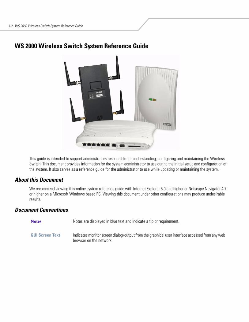
This guide is intended to support administrators responsible for understanding, configuring and maintaining the Wireless Switch. This document provides information for the system administrator to use during the initial setup and configuration of the system. It also serves as a reference guide for the administrator to use while updating or maintaining the system.
About this DocumentWe recommend viewing this online system reference guide with Internet Explorer 5.0 and higher or Netscape Navigator 4.7 or higher on a Microsoft Windows based PC. Viewing this document under other configurations may produce undesirable results.
Document Conventions
Notes Notes are displayed in blue text and indicate a tip or requirement.
GUI Screen Text Indicates monitor screen dialog/output from the graphical user interface accessed from any web browser on the network.
Product Overview 1-3
System OverviewThe WS 2000 Wireless Switch provides a low-cost, feature-rich option for sites with one to six Access Ports. The WS 2000 Wireless Switch works at the center of a network’s infrastructure to seamlessly and securely combine wireless LANs (WLANs) and wired networks. The switch sits on the network. Wireless Access Ports connect to one of the six available ports on the switch and the external wired network (WAN) connects to a single 10/100 Mbit/sec. WAN port.
Mobile units (MUs) associate with the switch via an Access Port. When an MU contacts the switch, the switch cell controller services attempt to authenticate the device for access to the network.
The WS 2000 Wireless Switch acts as a WAN/LAN gateway and a wired/wireless switch.
Management of Access PortsThis wireless switch provides six 10/100 Mbit/sec. LAN ports for internal wired or wireless traffic. Four of these ports provide IEEE 802.3af-compliant Power over Ethernet (PoE) support for devices that require power from the Ethernet connection (such as Access Ports). Administrators can configure the six ports to communicate with a private LAN or with an Access Port for a wireless LAN (WLAN). The switch provides up to four extended service set identifiers (ESSIDs) for each Access Port connected to the switch.
Firewall Security
The LAN and Access Ports are placed behind a user-configurable firewall that provides stateful packet inspection. The wireless switch performs network address translation (NAT) on packets passing to and from the WAN port. This combination provides enhanced security by monitoring communication with the wired network.
Wireless LAN (WLAN) Security
Administrators can configure security settings independently for each ESSID. Security settings and protocols available with this switch include:
• Kerberos
• WEP-40
• WEP-128
• 802.1x with RADIUS
• 802.1x with Shared Key
• KeyGuard
• WPA
• WPA2/CCMP
VPN Security
Virtual Private Networks (VPNs) are IP-based networks that use encryption and tunneling to give users remote access to a secure LAN. In essence, the trust relationship is extended from one LAN across the public network to another LAN, without sacrificing security. A VPN behaves similarly to a private network; however, because the data travels through the public network, it needs several layers of security. The WS 2000 Wireless Switch acts as a robust VPN gateway.
WS 2000 Wireless Switch System Reference Guide1-4
Hardware OverviewThe WS 2000 Wireless Switch provides a fully integrated solution for managing every aspect of connecting wireless LANs (WLANs) to a wired network. This wireless switch can connect directly to a cable or DSL modem, and can also connect to other wide area networks through a Layer 2/3 device (such as a switch or router). The switch includes the following features:
• One WAN (RJ-45) port for connection to a DSL modem, cable modem, or any other Layer 2/3 network device.
• Six 10/100 Mbit/sec. LAN (RJ-45) ports: four ports provide 802.3af “Power over Ethernet” (PoE) support; the other two do not provide power.
• Each port has two LEDs, one indicating the speed of the transmission (10 or 100 Mbit/sec.), the other indicating whether there is activity on the port. The four LAN ports with PoE have a third LED that indicates whether power is being delivered over the line to a power device (such as an Access Port). (See the WS 2000 Wireless Switch LED explanation for more information on the meaning of the different state of the LEDs.)
• A DB-9 serial port for direct access to the command-line interface from a PC. Use Symbol’s Null-Modem cable (Part No. 25-632878-0) for the best fitting connection.
• A CompactFlash slot that provides AirBEAM® support.
Technical Specifications
Physical Specifications• Width: 203 mm
• Height: 38 mm
• Depth: 286 mm
• Weight: 0.64 kg
Power Specifications• Maximum Power Consumption: 90-256 VAC, 47-63 Hz, 3A
• Operating Voltage: 48 VDC
• Operating Current: 1A
• Peak Current: 1.6A
Environmental Specifications• Operating Temperature: 0ºC to 40ºC
• Storage Temperature: -40ºC to 70ºC
• Operating Humidity: 10% to 85% Non-condensing
• Storage Humidity: 10% to 85% Non-condensing
• Operating Altitude: 2.4 km
• Storage Altitude: 4.6 km
Product Overview 1-5
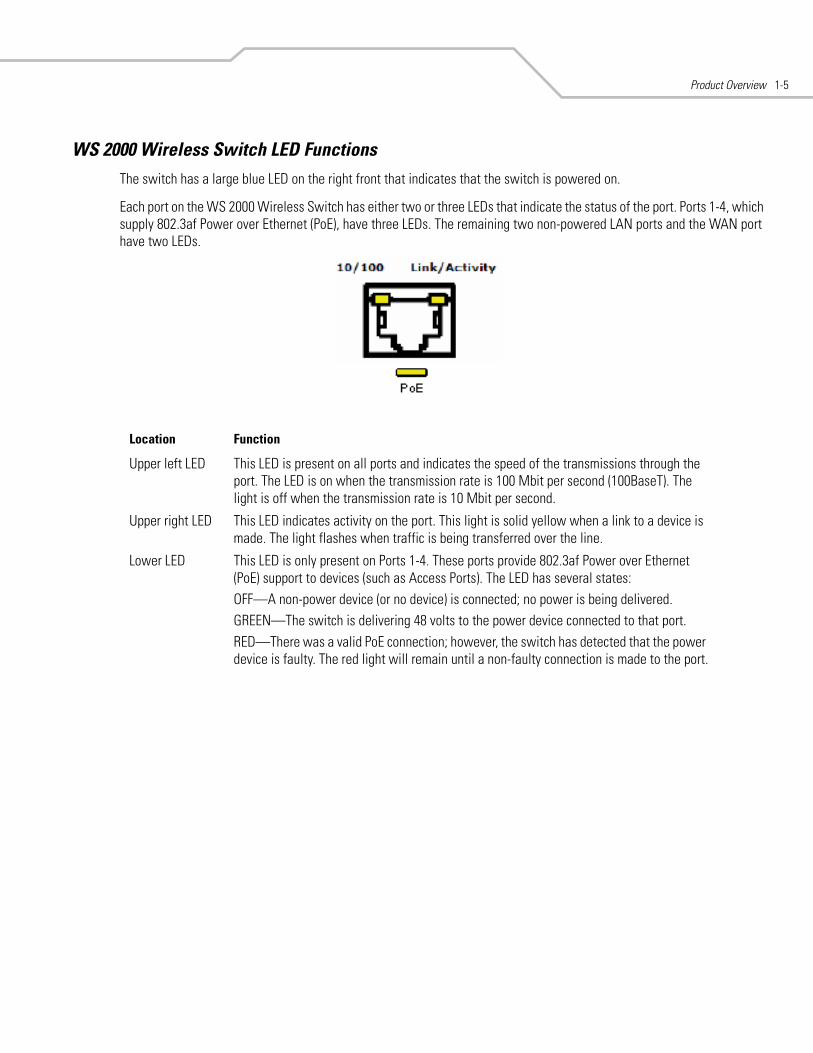
WS 2000 Wireless Switch LED FunctionsThe switch has a large blue LED on the right front that indicates that the switch is powered on.
Each port on the WS 2000 Wireless Switch has either two or three LEDs that indicate the status of the port. Ports 1-4, which supply 802.3af Power over Ethernet (PoE), have three LEDs. The remaining two non-powered LAN ports and the WAN port have two LEDs.
Location Function
Upper left LED This LED is present on all ports and indicates the speed of the transmissions through the port. The LED is on when the transmission rate is 100 Mbit per second (100BaseT). The light is off when the transmission rate is 10 Mbit per second.
Upper right LED This LED indicates activity on the port. This light is solid yellow when a link to a device is made. The light flashes when traffic is being transferred over the line.
Lower LED This LED is only present on Ports 1-4. These ports provide 802.3af Power over Ethernet (PoE) support to devices (such as Access Ports). The LED has several states:OFF—A non-power device (or no device) is connected; no power is being delivered.GREEN—The switch is delivering 48 volts to the power device connected to that port.RED—There was a valid PoE connection; however, the switch has detected that the power device is faulty. The red light will remain until a non-faulty connection is made to the port.
WS 2000 Wireless Switch System Reference Guide1-6
Software OverviewThe WS 2000 Wireless Switch software provides a fully integrated solution for managing every aspect of connecting Wireless LANs (WLANs) to a wired network, and includes the following components:
Operating System (OS) ServicesOperating System (OS) Services determine how the WS 2000 Wireless Switch communicates with existing network and operating system-centric software services, including:
• Dynamic Host Configuration Protocol (DHCP)
• Telnet and File Transfer Protocol (FTP/TFTP) servers
• The Simple Network Time Protocol (SNTP) client, used to keep switch time synchronized for Kerberos authentication
• A mechanism for setting up a redundant (secondary) switch that takes over if the primary switch fails
Cell Controller ServicesThe Cell Controller provides the ongoing communication between mobile units (MUs) on the Wireless LAN (WLAN) and the wired network. Cell Controller services perform the following:
• Initialize the Access Ports
• Maintain contact with Access Ports by sending a synchronized electronic “heartbeat” at regular intervals
• Track MUs when they roam from one location to another
• Manage security schemes based on system configuration
• Maintain system statistics
• Store policies and Access Port information
• Detect and manage rogue Access Ports
• Management of communications QoS
Gateway ServicesGateway services provide interconnectivity between the Cell Controller and the wired network, and include the following:
• System management through a Web-based Graphical User Interface (GUI) and SNMP
• 802.1x RADIUS client
• Security, including Secure Sockets Layer (SSL) and Firewall
• Network Address Translation (NAT), DHCP services, and Layer 3 Routing
• Virtual Private Network (VPN)

2Getting Started
Getting Started with the WS 2000 Wireless Switch. . . . . . . . . . . . . . . . . . . . . . . . . . . . . . . . . . . . . . . . . . . . . . 2-2Step 1: Install the Switch. . . . . . . . . . . . . . . . . . . . . . . . . . . . . . . . . . . . . . . . . . . . . . . . . . . . . . . . . . . . . . . . . . . 2-2Step 2: Set Up Administrative Communication to the Switch. . . . . . . . . . . . . . . . . . . . . . . . . . . . . . . . . . . . . . . 2-2Step 3: Set the Basic Switch Setting. . . . . . . . . . . . . . . . . . . . . . . . . . . . . . . . . . . . . . . . . . . . . . . . . . . . . . . . . . 2-4Step 3: Set the Basic Switch Setting. . . . . . . . . . . . . . . . . . . . . . . . . . . . . . . . . . . . . . . . . . . . . . . . . . . . . . . . . . 2-4Step 4: Configure the LAN Interface . . . . . . . . . . . . . . . . . . . . . . . . . . . . . . . . . . . . . . . . . . . . . . . . . . . . . . . . . . 2-5
Enable Subnet1 . . . . . . . . . . . . . . . . . . . . . . . . . . . . . . . . . . . . . . . . . . . . . . . . . . . . . . . . . . . . . . . . . . . . . . 2-5Step 5: Configure Subnet1 . . . . . . . . . . . . . . . . . . . . . . . . . . . . . . . . . . . . . . . . . . . . . . . . . . . . . . . . . . . . . . . . . . 2-6Step 6: Configure the WAN Interface . . . . . . . . . . . . . . . . . . . . . . . . . . . . . . . . . . . . . . . . . . . . . . . . . . . . . . . . . 2-6
Communicating with the Outside World . . . . . . . . . . . . . . . . . . . . . . . . . . . . . . . . . . . . . . . . . . . . . . . . . . . 2-7Setting Up Point-to-Point over Ethernet (PPPoE) Communication . . . . . . . . . . . . . . . . . . . . . . . . . . . . . . . . 2-8
Step 7: Enable Wireless LANs (WLANs) . . . . . . . . . . . . . . . . . . . . . . . . . . . . . . . . . . . . . . . . . . . . . . . . . . . . . . . 2-8Wireless Summary Area . . . . . . . . . . . . . . . . . . . . . . . . . . . . . . . . . . . . . . . . . . . . . . . . . . . . . . . . . . . . . . . 2-9
Step 8: Configure WLAN Security . . . . . . . . . . . . . . . . . . . . . . . . . . . . . . . . . . . . . . . . . . . . . . . . . . . . . . . . . . . . 2-9Setting the Authentication Method . . . . . . . . . . . . . . . . . . . . . . . . . . . . . . . . . . . . . . . . . . . . . . . . . . . . . . 2-10Setting the Encryption Method . . . . . . . . . . . . . . . . . . . . . . . . . . . . . . . . . . . . . . . . . . . . . . . . . . . . . . . . . 2-10Mobile Unit Access Control List (ACL) . . . . . . . . . . . . . . . . . . . . . . . . . . . . . . . . . . . . . . . . . . . . . . . . . . . . 2-11
Step 9: Test Connectivity . . . . . . . . . . . . . . . . . . . . . . . . . . . . . . . . . . . . . . . . . . . . . . . . . . . . . . . . . . . . . . . . . . 2-11Where to Go from Here? . . . . . . . . . . . . . . . . . . . . . . . . . . . . . . . . . . . . . . . . . . . . . . . . . . . . . . . . . . . . . . . . . . 2-12
WS 2000 Wireless Switch System Reference Guide2-2
Getting Started with the WS 2000 Wireless SwitchThis section provides just enough instruction to set up the WS 2000 Wireless Switch, connect an Access Port, and test communications with a single mobile unit (MU) and the wide area network (WAN). The configuration suggestions made here are just the minimum needed to test the hardware. Once finished with this section, additional configuration settings are required. This section covers the following topics:
Step 1: Install the SwitchTo install the WS 2000 Wireless Switch hardware, follow the directions in the WS 2000 Wireless Switch Quick Installation Guide found in the box with the switch and on the CD-ROM that is distributed with the switch. These instructions describe how to:
• Select a site (desk, wall, or rack) for the switch
• Install the switch using the appropriate accessories for the selected location
• Connect devices to WAN and LAN ports (using standard CAT-5 cables)
• Interpret the port LEDs on the front of the switch
After the switch is mounted and powered up, connect the following items to the switch:
1. Connect the WAN to the switch (using the WAN port) with a CAT-5 Ethernet cable. The LEDs for that port should start to flash.
2. Connect an Access Port to the switch using a CAT-5 Ethernet cable using one of the six LAN ports. If the Access Port requires PPPoE, connect the Access Port in ports 1, 2, 3, or 4. Ports 5 and 6 do not provide power.
3. Have a mobile “wireless” device available to test communication with the Access Port.
Access Ports must be connected to the LAN ports of the wireless switch to enable configuration of the Access Port related settings.
Step 2: Set Up Administrative Communication to the SwitchBefore the configuration process can begin, establish a link with the wireless switch.
1. Connect a “wired” computer to the switch (in any one of the available LAN ports) using a standard CAT-5 cable.
2. Set up the computer for TCP/IP DHCP network addressing and make sure that the DNS settings are not hardcoded.
3. Start up Internet Explorer (with Sun Micro systems’ Java Runtime Environment (JRE) 1.4 or higher installed) and type the following IP address in the address field: 192.168.0.1
For optimum compatibility use Sun Microsystems’ JRE 1.4 or higher (available from Sun’s website), and be sure to disable Microsoft’s Java Virtual Machine if it is installed.
The following screen is displayed.
• Step 1: Install the switch and connect it to the WAN, a standalone computer, and an Access Port
• Step 2: Set up administrative communication to the switch
• Step 3: Set the basic switch settings • Step 4: Configure the LAN interface
• Step 5: Configure Subnet1 • Step 6: Configure the WAN Interface• Step 7: Enable Wireless LANs (WLANs) • Step 8: Configure WLAN Security • Step 9: Test Connectivity
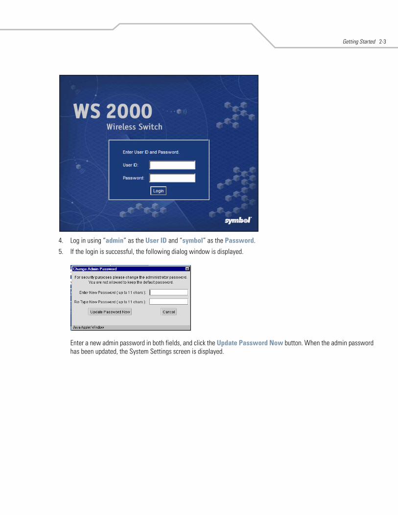
Getting Started 2-3
4. Log in using “admin” as the User ID and “symbol” as the Password.
5. If the login is successful, the following dialog window is displayed.
Enter a new admin password in both fields, and click the Update Password Now button. When the admin password has been updated, the System Settings screen is displayed.
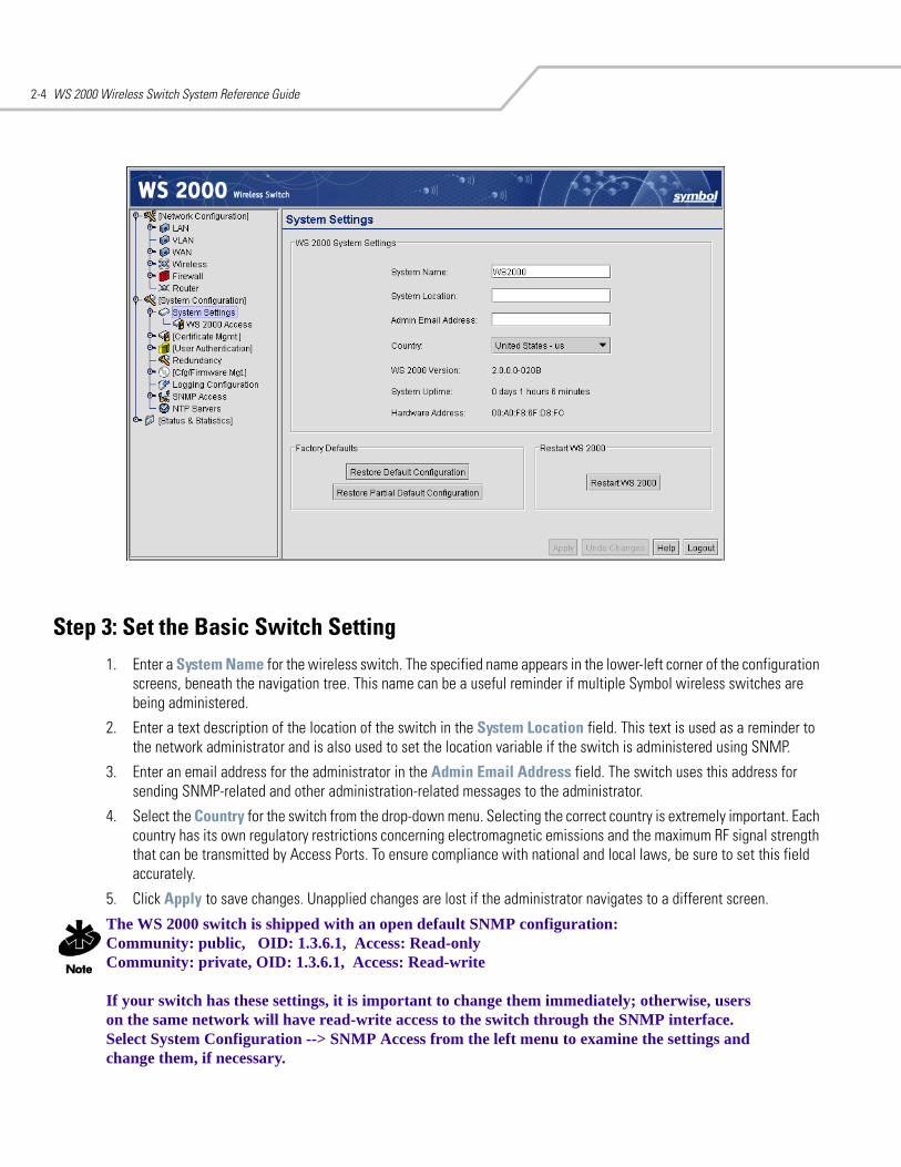
WS 2000 Wireless Switch System Reference Guide2-4
Step 3: Set the Basic Switch Setting1. Enter a System Name for the wireless switch. The specified name appears in the lower-left corner of the configuration
screens, beneath the navigation tree. This name can be a useful reminder if multiple Symbol wireless switches are being administered.
2. Enter a text description of the location of the switch in the System Location field. This text is used as a reminder to the network administrator and is also used to set the location variable if the switch is administered using SNMP.
3. Enter an email address for the administrator in the Admin Email Address field. The switch uses this address for sending SNMP-related and other administration-related messages to the administrator.
4. Select the Country for the switch from the drop-down menu. Selecting the correct country is extremely important. Each country has its own regulatory restrictions concerning electromagnetic emissions and the maximum RF signal strength that can be transmitted by Access Ports. To ensure compliance with national and local laws, be sure to set this field accurately.
5. Click Apply to save changes. Unapplied changes are lost if the administrator navigates to a different screen.
The WS 2000 switch is shipped with an open default SNMP configuration:Community: public, OID: 1.3.6.1, Access: Read-onlyCommunity: private, OID: 1.3.6.1, Access: Read-write
If your switch has these settings, it is important to change them immediately; otherwise, users on the same network will have read-write access to the switch through the SNMP interface. Select System Configuration --> SNMP Access from the left menu to examine the settings and change them, if necessary.
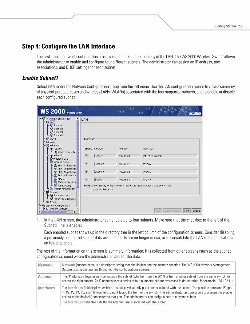
Getting Started 2-5
Step 4: Configure the LAN InterfaceThe first step of network configuration process is to figure out the topology of the LAN. The WS 2000 Wireless Switch allows the administrator to enable and configure four different subnets. The administrator can assign an IP address, port associations, and DHCP settings for each subnet.
Enable Subnet1Select LAN under the Network Configuration group from the left menu. Use the LAN configuration screen to view a summary of physical-port addresses and wireless LANs (WLANs) associated with the four supported subnets, and to enable or disable each configured subnet.
1. In the LAN screen, the administrator can enable up to four subnets. Make sure that the checkbox to the left of the Subnet1 line is enabled.
Each enabled subnet shows up in the directory tree in the left column of the configuration screens. Consider disabling a previously configured subnet if its assigned ports are no longer in use, or to consolidate the LAN’s communications on fewer subnets.
The rest of the information on this screen is summary information; it is collected from other screens (such as the subnet configuration screens) where the administrator can set the data.
Network Network (subnet) name is a descriptive string that should describe the subnet’s function. The WS 2000 Network Management System uses subnet names throughout the configurations screens.
Address This IP address allows users from outside the subnet (whether from the WAN or from another subnet from the same switch) to access the right subnet. An IP address uses a series of four numbers that are expressed in dot notation, for example, 194.182.1.1.
Interfaces The Interfaces field displays which of the six physical LAN ports are associated with the subnet. The possible ports are: P1 (port 1), P2, P3, P4, P5, and P6 (from left to right facing the front of the switch). The administrator assigns a port to a subnet to enable access to the device(s) connected to that port. The administrator can assign a port to only one subnet.The Interfaces field also lists the WLANs that are associated with the subnet.
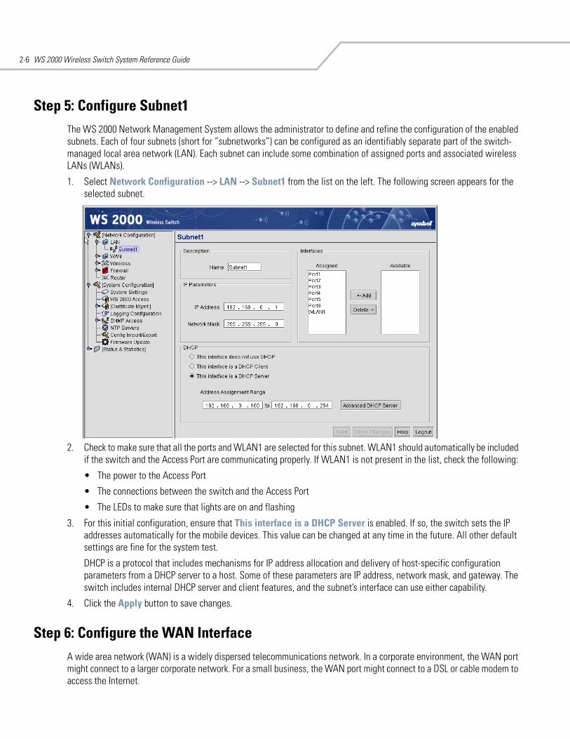
WS 2000 Wireless Switch System Reference Guide2-6
Step 5: Configure Subnet1The WS 2000 Network Management System allows the administrator to define and refine the configuration of the enabled subnets. Each of four subnets (short for “subnetworks”) can be configured as an identifiably separate part of the switch-managed local area network (LAN). Each subnet can include some combination of assigned ports and associated wireless LANs (WLANs).
1. Select Network Configuration --> LAN --> Subnet1 from the list on the left. The following screen appears for the selected subnet.
2. Check to make sure that all the ports and WLAN1 are selected for this subnet. WLAN1 should automatically be included if the switch and the Access Port are communicating properly. If WLAN1 is not present in the list, check the following:
• The power to the Access Port
• The connections between the switch and the Access Port
• The LEDs to make sure that lights are on and flashing
3. For this initial configuration, ensure that This interface is a DHCP Server is enabled. If so, the switch sets the IP addresses automatically for the mobile devices. This value can be changed at any time in the future. All other default settings are fine for the system test.
DHCP is a protocol that includes mechanisms for IP address allocation and delivery of host-specific configuration parameters from a DHCP server to a host. Some of these parameters are IP address, network mask, and gateway. The switch includes internal DHCP server and client features, and the subnet’s interface can use either capability.
4. Click the Apply button to save changes.
Step 6: Configure the WAN InterfaceA wide area network (WAN) is a widely dispersed telecommunications network. In a corporate environment, the WAN port might connect to a larger corporate network. For a small business, the WAN port might connect to a DSL or cable modem to access the Internet.
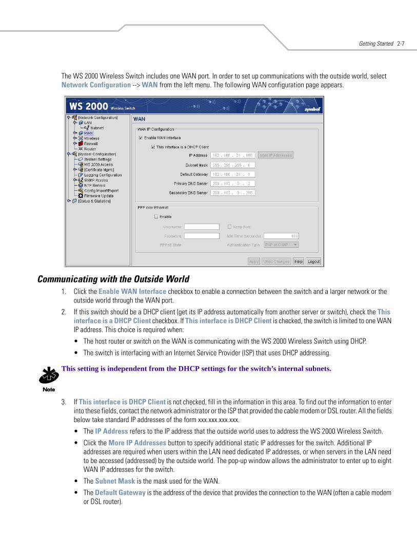
Getting Started 2-7
The WS 2000 Wireless Switch includes one WAN port. In order to set up communications with the outside world, select Network Configuration --> WAN from the left menu. The following WAN configuration page appears.
Communicating with the Outside World1. Click the Enable WAN Interface checkbox to enable a connection between the switch and a larger network or the
outside world through the WAN port.
2. If this switch should be a DHCP client (get its IP address automatically from another server or switch), check the This interface is a DHCP Client checkbox. If This interface is DHCP Client is checked, the switch is limited to one WAN IP address. This choice is required when:
• The host router or switch on the WAN is communicating with the WS 2000 Wireless Switch using DHCP.
• The switch is interfacing with an Internet Service Provider (ISP) that uses DHCP addressing.
This setting is independent from the DHCP settings for the switch’s internal subnets.
3. If This interface is DHCP Client is not checked, fill in the information in this area. To find out the information to enter into these fields, contact the network administrator or the ISP that provided the cable modem or DSL router. All the fields below take standard IP addresses of the form xxx.xxx.xxx.xxx.
• The IP Address refers to the IP address that the outside world uses to address the WS 2000 Wireless Switch.
• Click the More IP Addresses button to specify additional static IP addresses for the switch. Additional IP addresses are required when users within the LAN need dedicated IP addresses, or when servers in the LAN need to be accessed (addressed) by the outside world. The pop-up window allows the administrator to enter up to eight WAN IP addresses for the switch.
• The Subnet Mask is the mask used for the WAN.
• The Default Gateway is the address of the device that provides the connection to the WAN (often a cable modem or DSL router).
WS 2000 Wireless Switch System Reference Guide2-8
• The two DNS Server fields specify DNS addresses of servers that can translate domain names, such as www.symbol.com, into IP addresses that the network uses when passing information. The Secondary DNS Server acts as a backup to the Primary DNS Server when the primary server is not responding.
Setting Up Point-to-Point over Ethernet (PPPoE) CommunicationPPPoE provides the ability to connect a network of hosts through a simple device to a remote access concentrator. Many DSL providers require that their clients communicate using this protocol. The facility allows the ISP to control access, billing, and type of service provided to clients on a per-user or per-site basis. Check with the network administrator or ISP to determine whether to enable this feature, and, if so, find out the username and password required for authentication.
1. Check Enable in the PPP over Ethernet area to enable the PPPoE protocol for high-speed connections.
2. Enter the Username and Password required for authentication. The username and password are for the switch’s router to use when connecting to the ISP. When the Internet session starts, the ISP authenticates the username.
3. Set the Idle Time to an appropriate number. This number is the amount of time the PPPoE connection will be idle before it disconnects. The 10000 second (default idle time is appropriate for most situations).
4. Check Keep Alive to instruct the switch to continue occasional communications over the WAN even when client communications to the WAN are idle. Some ISPs terminate inactive connections, while others do not. In either case, enabling Keep-Alive mode keeps the switch’s WAN connection alive, even when there is no traffic. If the ISP drops the connection after so much idle time, the switch automatically reestablishes the connection to the ISP.
5. Select the appropriate WAN authentication method from the drop-down menu. Collect this information from the network administrator. Select between None, PAP, CHAP, or PAP or CHAP.
6. Click the Apply button to save changes.
Step 7: Enable Wireless LANs (WLANs)The WS 2000 Wireless Switch works either in a wired or wireless environment; however, the power of the switch is associated with its support of wireless networks. In order to use the wireless features of the switch, the administrator needs to enable up to four wireless LANs (WLANs).
To start the WLAN configuration process, select the Network Configuration --> Wireless item from the left menu. The following Wireless summary screen appears.
CHAP A type of authentication in which the person logging in uses secret information and some special mathematical operations to come up with a number value. The server the person is logging into knows the same secret value and performs the same mathematical operations. If the results match, the person is authorized to access the server. One of the numbers in the mathematical operation is changed after every log-in, to protect against an intruder secretly copying a valid authentication session and replaying it later to log in.
PAP An identity verification method used to send a username and password over a network to a computer that compares the username and password to a table listing authorized users. This method of authentication is less secure, because the username and password travel as clear text that a hacker could read.
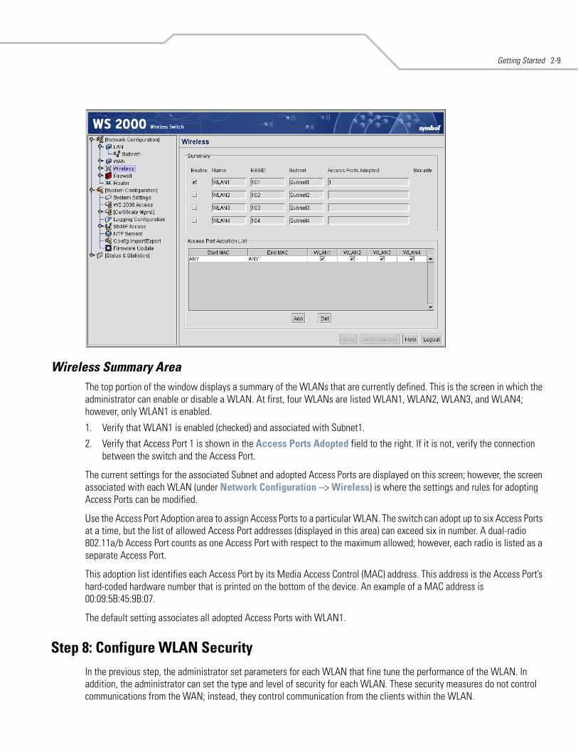
Getting Started 2-9
Wireless Summary AreaThe top portion of the window displays a summary of the WLANs that are currently defined. This is the screen in which the administrator can enable or disable a WLAN. At first, four WLANs are listed WLAN1, WLAN2, WLAN3, and WLAN4; however, only WLAN1 is enabled.
1. Verify that WLAN1 is enabled (checked) and associated with Subnet1.
2. Verify that Access Port 1 is shown in the Access Ports Adopted field to the right. If it is not, verify the connection between the switch and the Access Port.
The current settings for the associated Subnet and adopted Access Ports are displayed on this screen; however, the screen associated with each WLAN (under Network Configuration --> Wireless) is where the settings and rules for adopting Access Ports can be modified.
Use the Access Port Adoption area to assign Access Ports to a particular WLAN. The switch can adopt up to six Access Ports at a time, but the list of allowed Access Port addresses (displayed in this area) can exceed six in number. A dual-radio 802.11a/b Access Port counts as one Access Port with respect to the maximum allowed; however, each radio is listed as a separate Access Port.
This adoption list identifies each Access Port by its Media Access Control (MAC) address. This address is the Access Port’s hard-coded hardware number that is printed on the bottom of the device. An example of a MAC address is 00:09:5B:45:9B:07.
The default setting associates all adopted Access Ports with WLAN1.
Step 8: Configure WLAN SecurityIn the previous step, the administrator set parameters for each WLAN that fine tune the performance of the WLAN. In addition, the administrator can set the type and level of security for each WLAN. These security measures do not control communications from the WAN; instead, they control communication from the clients within the WLAN.
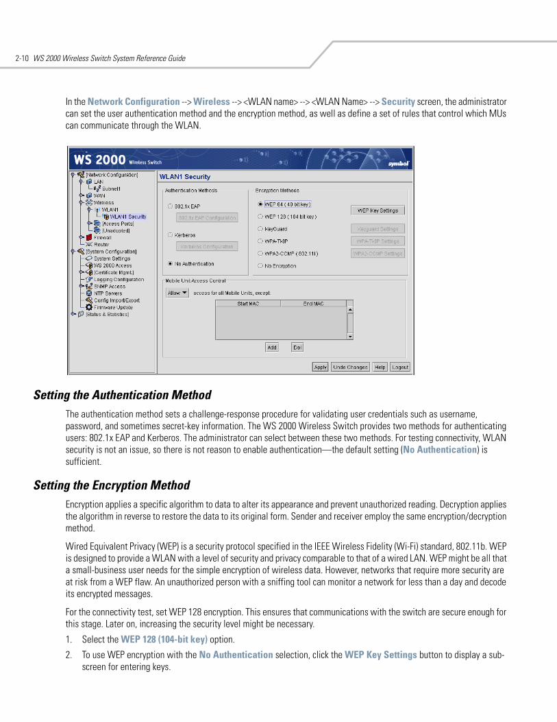
WS 2000 Wireless Switch System Reference Guide2-10
In the Network Configuration --> Wireless --> <WLAN name> --> <WLAN Name> --> Security screen, the administrator can set the user authentication method and the encryption method, as well as define a set of rules that control which MUs can communicate through the WLAN.
Setting the Authentication MethodThe authentication method sets a challenge-response procedure for validating user credentials such as username, password, and sometimes secret-key information. The WS 2000 Wireless Switch provides two methods for authenticating users: 802.1x EAP and Kerberos. The administrator can select between these two methods. For testing connectivity, WLAN security is not an issue, so there is not reason to enable authentication—the default setting (No Authentication) is sufficient.
Setting the Encryption MethodEncryption applies a specific algorithm to data to alter its appearance and prevent unauthorized reading. Decryption applies the algorithm in reverse to restore the data to its original form. Sender and receiver employ the same encryption/decryption method.
Wired Equivalent Privacy (WEP) is a security protocol specified in the IEEE Wireless Fidelity (Wi-Fi) standard, 802.11b. WEP is designed to provide a WLAN with a level of security and privacy comparable to that of a wired LAN. WEP might be all that a small-business user needs for the simple encryption of wireless data. However, networks that require more security are at risk from a WEP flaw. An unauthorized person with a sniffing tool can monitor a network for less than a day and decode its encrypted messages.
For the connectivity test, set WEP 128 encryption. This ensures that communications with the switch are secure enough for this stage. Later on, increasing the security level might be necessary.
1. Select the WEP 128 (104-bit key) option.
2. To use WEP encryption with the No Authentication selection, click the WEP Key Settings button to display a sub-screen for entering keys.
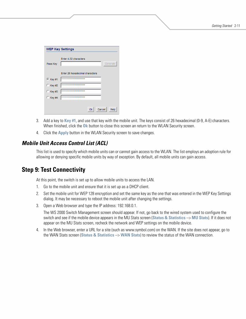
Getting Started 2-11
3. Add a key to Key #1, and use that key with the mobile unit. The keys consist of 26 hexadecimal (0-9, A-E) characters. When finished, click the Ok button to close this screen an return to the WLAN Security screen.
4. Click the Apply button in the WLAN Security screen to save changes.
Mobile Unit Access Control List (ACL)This list is used to specify which mobile units can or cannot gain access to the WLAN. The list employs an adoption rule for allowing or denying specific mobile units by way of exception. By default, all mobile units can gain access.
Step 9: Test ConnectivityAt this point, the switch is set up to allow mobile units to access the LAN.
1. Go to the mobile unit and ensure that it is set up as a DHCP client.
2. Set the mobile unit for WEP 128 encryption and set the same key as the one that was entered in the WEP Key Settings dialog. It may be necessary to reboot the mobile unit after changing the settings.
3. Open a Web browser and type the IP address: 192.168.0.1.
The WS 2000 Switch Management screen should appear. If not, go back to the wired system used to configure the switch and see if the mobile device appears in the MU Stats screen (Status & Statistics --> MU Stats). If it does not appear on the MU Stats screen, recheck the network and WEP settings on the mobile device.
4. In the Web browser, enter a URL for a site (such as www.symbol.com) on the WAN. If the site does not appear, go to the WAN Stats screen (Status & Statistics --> WAN Stats) to review the status of the WAN connection.
WS 2000 Wireless Switch System Reference Guide2-12
Where to Go from Here?When full connectivity has been verified, the switch can be fully configured to meet the needs of the organization. Refer to the two case studies provided with this reference for specific installation examples. These case studies describe the environment, the desired features, and the configuration selections that were made in two different scenarios.
• Case 1: Retail Use Case(with handheld terminals, wireless printers, wired POS, secured access to in-store server, and public access to WAN)
• Case 2: Field Office Use Case(with 3 WAN IP addresses, VPN passthrough, RADIUS server, and full-access between subnets)
3LAN/Subnet Configuration
Enabling Subnets for the LAN Interface . . . . . . . . . . . . . . . . . . . . . . . . . . . . . . . . . . . . . . . . . . . . . . . . . . . . . . . 3-2Defining Subnets . . . . . . . . . . . . . . . . . . . . . . . . . . . . . . . . . . . . . . . . . . . . . . . . . . . . . . . . . . . . . . . . . . . . . 3-2
Configuring Subnets. . . . . . . . . . . . . . . . . . . . . . . . . . . . . . . . . . . . . . . . . . . . . . . . . . . . . . . . . . . . . . . . . . . . . . . 3-3The DHCP Configuration . . . . . . . . . . . . . . . . . . . . . . . . . . . . . . . . . . . . . . . . . . . . . . . . . . . . . . . . . . . . . . . 3-4Advanced DHCP Settings . . . . . . . . . . . . . . . . . . . . . . . . . . . . . . . . . . . . . . . . . . . . . . . . . . . . . . . . . . . . . . . 3-5
Configuring Subnet Access . . . . . . . . . . . . . . . . . . . . . . . . . . . . . . . . . . . . . . . . . . . . . . . . . . . . . . . . . . . . . . . . . 3-5The Access Overview Table . . . . . . . . . . . . . . . . . . . . . . . . . . . . . . . . . . . . . . . . . . . . . . . . . . . . . . . . . . . . . 3-6The Access Exception Area . . . . . . . . . . . . . . . . . . . . . . . . . . . . . . . . . . . . . . . . . . . . . . . . . . . . . . . . . . . . . 3-6
Advanced Subnet Access Settings . . . . . . . . . . . . . . . . . . . . . . . . . . . . . . . . . . . . . . . . . . . . . . . . . . . . . . . . . . . 3-8Virtual LAN (VLAN) Configuration . . . . . . . . . . . . . . . . . . . . . . . . . . . . . . . . . . . . . . . . . . . . . . . . . . . . . . . . . . . 3-11
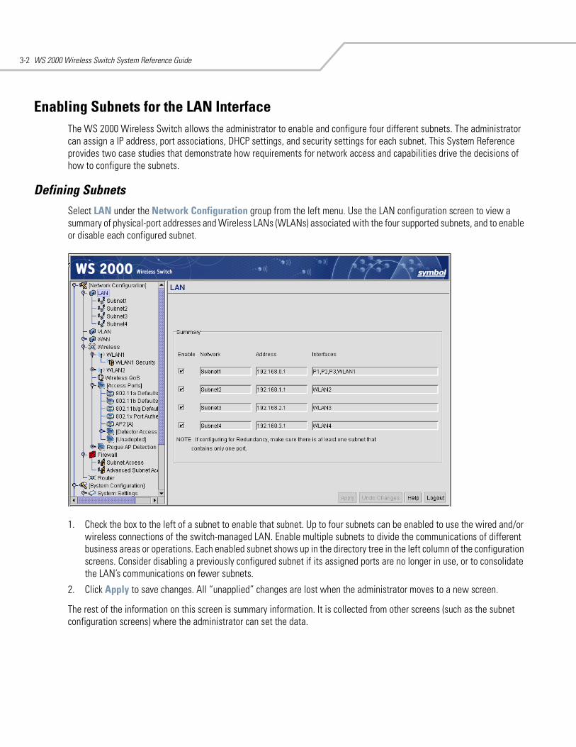
WS 2000 Wireless Switch System Reference Guide3-2
Enabling Subnets for the LAN InterfaceThe WS 2000 Wireless Switch allows the administrator to enable and configure four different subnets. The administrator can assign a IP address, port associations, DHCP settings, and security settings for each subnet. This System Reference provides two case studies that demonstrate how requirements for network access and capabilities drive the decisions of how to configure the subnets.
Defining SubnetsSelect LAN under the Network Configuration group from the left menu. Use the LAN configuration screen to view a summary of physical-port addresses and Wireless LANs (WLANs) associated with the four supported subnets, and to enable or disable each configured subnet.
1. Check the box to the left of a subnet to enable that subnet. Up to four subnets can be enabled to use the wired and/or wireless connections of the switch-managed LAN. Enable multiple subnets to divide the communications of different business areas or operations. Each enabled subnet shows up in the directory tree in the left column of the configuration screens. Consider disabling a previously configured subnet if its assigned ports are no longer in use, or to consolidate the LAN’s communications on fewer subnets.
2. Click Apply to save changes. All “unapplied” changes are lost when the administrator moves to a new screen.
The rest of the information on this screen is summary information. It is collected from other screens (such as the subnet configuration screens) where the administrator can set the data.
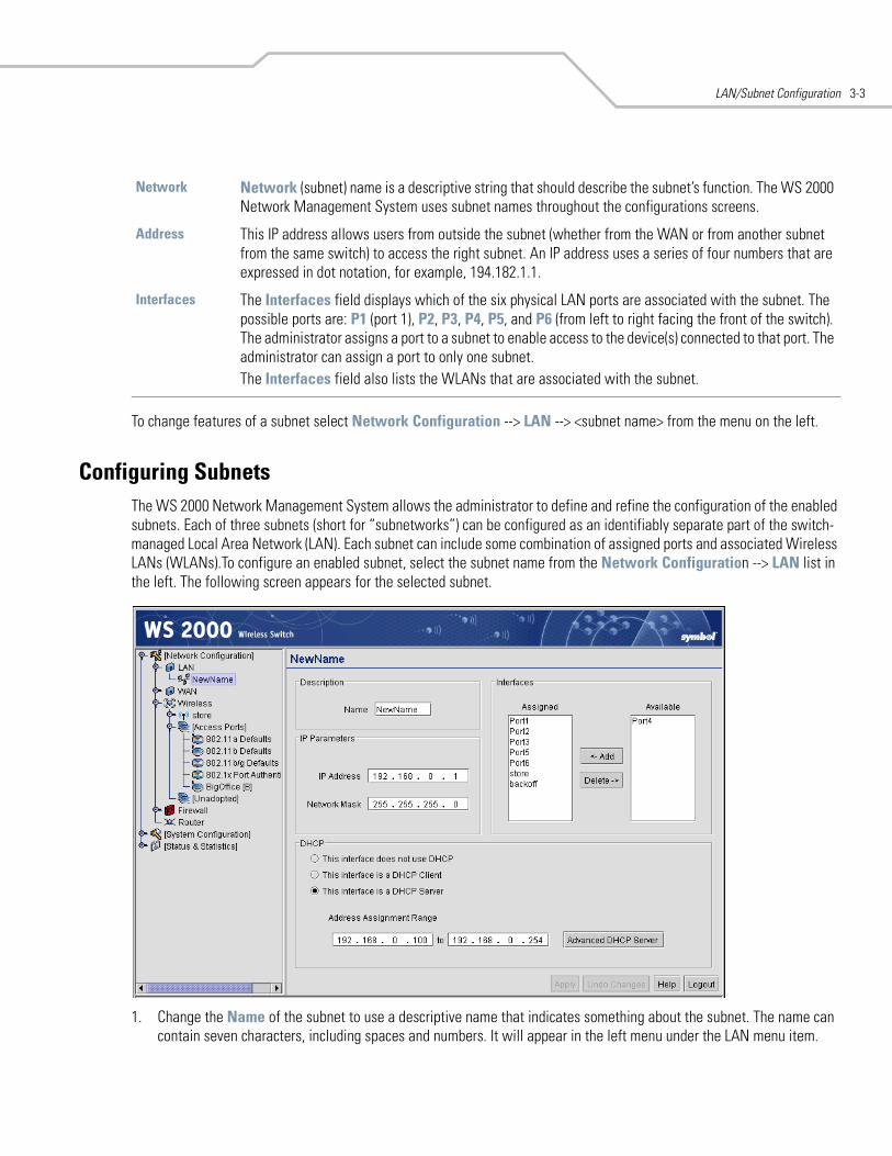
LAN/Subnet Configuration 3-3
To change features of a subnet select Network Configuration --> LAN --> <subnet name> from the menu on the left.
Configuring SubnetsThe WS 2000 Network Management System allows the administrator to define and refine the configuration of the enabled subnets. Each of three subnets (short for “subnetworks”) can be configured as an identifiably separate part of the switch-managed Local Area Network (LAN). Each subnet can include some combination of assigned ports and associated Wireless LANs (WLANs).To configure an enabled subnet, select the subnet name from the Network Configuration --> LAN list in the left. The following screen appears for the selected subnet.
1. Change the Name of the subnet to use a descriptive name that indicates something about the subnet. The name can contain seven characters, including spaces and numbers. It will appear in the left menu under the LAN menu item.
Network Network (subnet) name is a descriptive string that should describe the subnet’s function. The WS 2000 Network Management System uses subnet names throughout the configurations screens.
Address This IP address allows users from outside the subnet (whether from the WAN or from another subnet from the same switch) to access the right subnet. An IP address uses a series of four numbers that are expressed in dot notation, for example, 194.182.1.1.
Interfaces The Interfaces field displays which of the six physical LAN ports are associated with the subnet. The possible ports are: P1 (port 1), P2, P3, P4, P5, and P6 (from left to right facing the front of the switch). The administrator assigns a port to a subnet to enable access to the device(s) connected to that port. The administrator can assign a port to only one subnet.The Interfaces field also lists the WLANs that are associated with the subnet.
WS 2000 Wireless Switch System Reference Guide3-4
2. Set an IP address to be used for the subnet. This is how the switch will refer specifically to this subnet. This could be a WAN address; but more likely it will be a non-routable address. An IP address uses a series of four numbers that are expressed in dot notation, for example, 194.182.1.1.
3. Set the Network Mask for the IP address. A network mask uses a series of four numbers that are expressed in dot notation, similar to an IP number. For example, 255.255.255.0 is a network mask.
4. Select a port or WLAN from the Interfaces drop-down menu to associate it with the subnet. Six LAN ports are available on the switch. Assign from one to six ports to a subnet. Two subnets cannot use the same port. However, multiple ports can be assigned to one subnet.
Four WLANs are available. WLAN assignments are logical designations. Associate from zero to three WLANs with a subnet. Two subnets cannot use the same WLAN. However, multiple WLANs can be associated with one subnet. If two or three WLANs are associated with one subnet, each port dedicated to that subnet can use any of the associated WLANs.
5. Click the Add button to add it to the Interfaces list.
Note that wireless devices cannot access the switch unless a WLAN is configured and associated with a subnet. (This process is described in Configuring Wireless LANs.)
The DHCP ConfigurationDHCP is a protocol that includes mechanisms for IP address allocation and delivery of host-specific configuration parameters from a DHCP server to a host. Some of these parameters are IP address, network mask, and gateway. The switch includes internal DHCP server and client features, and the subnet’s interface can use either capability.
1. Click the appropriate radio button to select one DHCP setting for the subnet’s interfaces:
• Select This interface does not use DHCP to disable DHCP on this subnet and specify IP addresses manually.
• Select This interface is a DHCP Client if this subnet obtains IP parameters from a DHCP server outside the switch.
• Select This interface is a DHCP Server to enable the switch’s DHCP server features.
2. If This interface is a DHCP Server is the selected option, fill in the Address Assignment Range fields. These fields allow the administrator to assign a range of IP addresses to devices as they connect.
3. Set the Advanced Settings, if necessary.
4. Click the Apply button to save all changes.
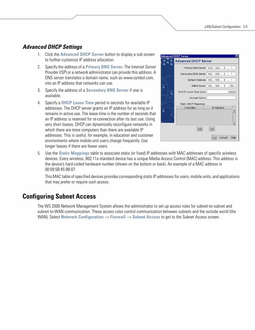
LAN/Subnet Configuration 3-5
Advanced DHCP Settings1. Click the Advanced DHCP Server button to display a sub-screen
to further customize IP address allocation.
2. Specify the address of a Primary DNS Server. The Internet Server Provider (ISP) or a network administrator can provide this address. A DNS server translates a domain name, such as www.symbol.com, into an IP address that networks can use.
3. Specify the address of a Secondary DNS Server if one is available.
4. Specify a DHCP Lease Time period in seconds for available IP addresses. The DHCP server grants an IP address for as long as it remains in active use. The lease time is the number of seconds that an IP address is reserved for re-connection after its last use. Using very short leases, DHCP can dynamically reconfigure networks in which there are more computers than there are available IP addresses. This is useful, for example, in education and customer environments where mobile-unit users change frequently. Use longer leases if there are fewer users.
5. Use the Static Mappings table to associate static (or fixed) IP addresses with MAC addresses of specific wireless devices. Every wireless, 802.11x-standard device has a unique Media Access Control (MAC) address. This address is the device’s hard-coded hardware number (shown on the bottom or back). An example of a MAC address is 00:09:5B:45:9B:07.
This MAC table of specified devices provides corresponding static IP addresses for users, mobile units, and applications that may prefer or require such access.
Configuring Subnet AccessThe WS 2000 Network Management System allows the administrator to set up access rules for subnet-to-subnet and subnet-to-WAN communication. These access rules control communication between subnets and the outside world (the WAN). Select Network Configuration --> Firewall --> Subnet Access to get to the Subnet Access screen.
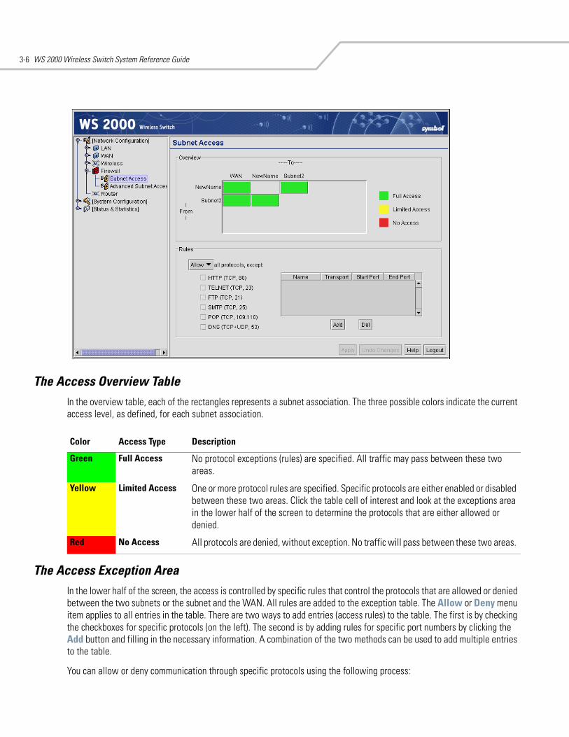
WS 2000 Wireless Switch System Reference Guide3-6
The Access Overview TableIn the overview table, each of the rectangles represents a subnet association. The three possible colors indicate the current access level, as defined, for each subnet association.
The Access Exception AreaIn the lower half of the screen, the access is controlled by specific rules that control the protocols that are allowed or denied between the two subnets or the subnet and the WAN. All rules are added to the exception table. The Allow or Deny menu item applies to all entries in the table. There are two ways to add entries (access rules) to the table. The first is by checking the checkboxes for specific protocols (on the left). The second is by adding rules for specific port numbers by clicking the Add button and filling in the necessary information. A combination of the two methods can be used to add multiple entries to the table.
You can allow or deny communication through specific protocols using the following process:
Color Access Type Description
Green Full Access No protocol exceptions (rules) are specified. All traffic may pass between these two areas.
Yellow Limited Access One or more protocol rules are specified. Specific protocols are either enabled or disabled between these two areas. Click the table cell of interest and look at the exceptions area in the lower half of the screen to determine the protocols that are either allowed or denied.
Red No Access All protocols are denied, without exception. No traffic will pass between these two areas.
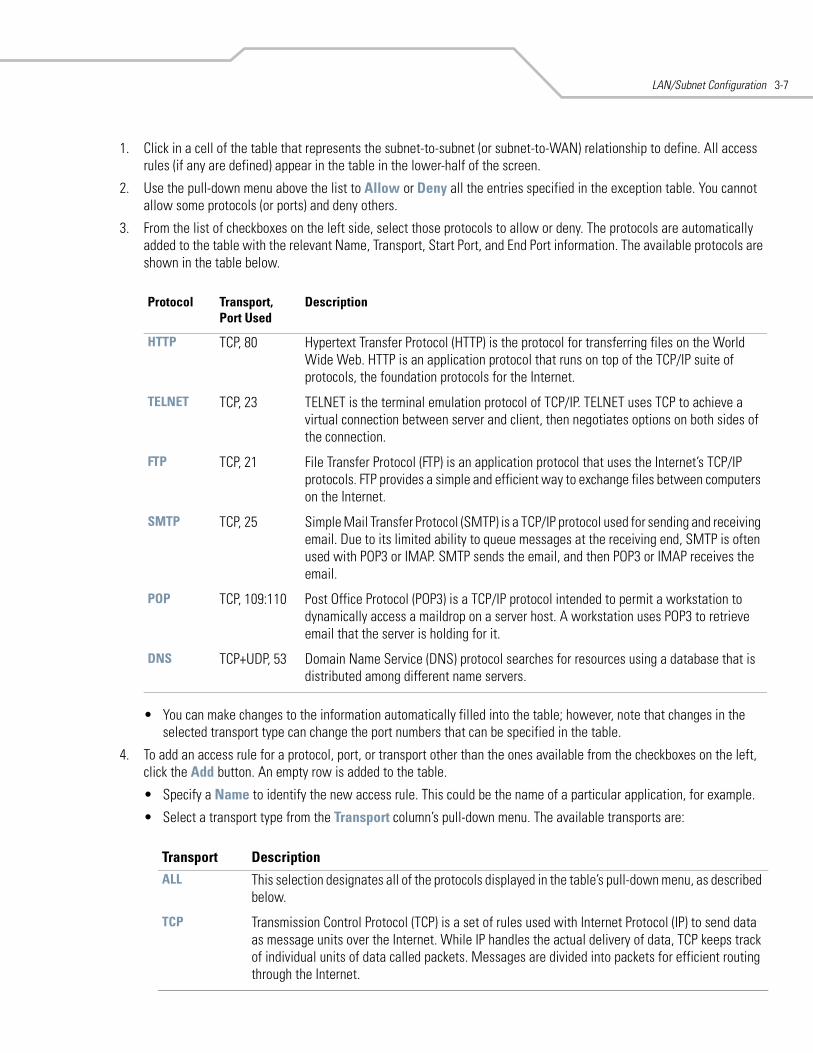
LAN/Subnet Configuration 3-7
1. Click in a cell of the table that represents the subnet-to-subnet (or subnet-to-WAN) relationship to define. All access rules (if any are defined) appear in the table in the lower-half of the screen.
2. Use the pull-down menu above the list to Allow or Deny all the entries specified in the exception table. You cannot allow some protocols (or ports) and deny others.
3. From the list of checkboxes on the left side, select those protocols to allow or deny. The protocols are automatically added to the table with the relevant Name, Transport, Start Port, and End Port information. The available protocols are shown in the table below.
• You can make changes to the information automatically filled into the table; however, note that changes in the selected transport type can change the port numbers that can be specified in the table.
4. To add an access rule for a protocol, port, or transport other than the ones available from the checkboxes on the left, click the Add button. An empty row is added to the table.
• Specify a Name to identify the new access rule. This could be the name of a particular application, for example.
• Select a transport type from the Transport column’s pull-down menu. The available transports are:
Protocol Transport, Port Used
Description
HTTP TCP, 80 Hypertext Transfer Protocol (HTTP) is the protocol for transferring files on the World Wide Web. HTTP is an application protocol that runs on top of the TCP/IP suite of protocols, the foundation protocols for the Internet.
TELNET TCP, 23 TELNET is the terminal emulation protocol of TCP/IP. TELNET uses TCP to achieve a virtual connection between server and client, then negotiates options on both sides of the connection.
FTP TCP, 21 File Transfer Protocol (FTP) is an application protocol that uses the Internet’s TCP/IP protocols. FTP provides a simple and efficient way to exchange files between computers on the Internet.
SMTP TCP, 25 Simple Mail Transfer Protocol (SMTP) is a TCP/IP protocol used for sending and receiving email. Due to its limited ability to queue messages at the receiving end, SMTP is often used with POP3 or IMAP. SMTP sends the email, and then POP3 or IMAP receives the email.
POP TCP, 109:110 Post Office Protocol (POP3) is a TCP/IP protocol intended to permit a workstation to dynamically access a maildrop on a server host. A workstation uses POP3 to retrieve email that the server is holding for it.
DNS TCP+UDP, 53 Domain Name Service (DNS) protocol searches for resources using a database that is distributed among different name servers.
Transport DescriptionALL This selection designates all of the protocols displayed in the table’s pull-down menu, as described
below.
TCP Transmission Control Protocol (TCP) is a set of rules used with Internet Protocol (IP) to send data as message units over the Internet. While IP handles the actual delivery of data, TCP keeps track of individual units of data called packets. Messages are divided into packets for efficient routing through the Internet.
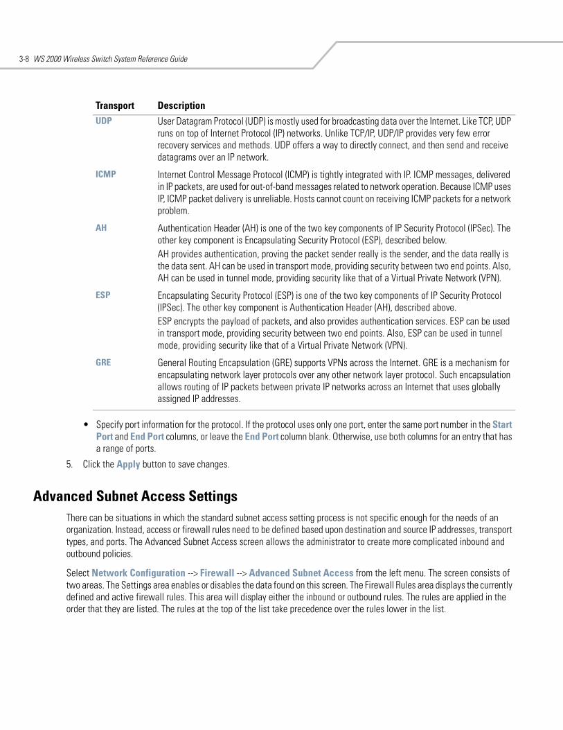
WS 2000 Wireless Switch System Reference Guide3-8
• Specify port information for the protocol. If the protocol uses only one port, enter the same port number in the Start Port and End Port columns, or leave the End Port column blank. Otherwise, use both columns for an entry that has a range of ports.
5. Click the Apply button to save changes.
Advanced Subnet Access SettingsThere can be situations in which the standard subnet access setting process is not specific enough for the needs of an organization. Instead, access or firewall rules need to be defined based upon destination and source IP addresses, transport types, and ports. The Advanced Subnet Access screen allows the administrator to create more complicated inbound and outbound policies.
Select Network Configuration --> Firewall --> Advanced Subnet Access from the left menu. The screen consists of two areas. The Settings area enables or disables the data found on this screen. The Firewall Rules area displays the currently defined and active firewall rules. This area will display either the inbound or outbound rules. The rules are applied in the order that they are listed. The rules at the top of the list take precedence over the rules lower in the list.
UDP User Datagram Protocol (UDP) is mostly used for broadcasting data over the Internet. Like TCP, UDP runs on top of Internet Protocol (IP) networks. Unlike TCP/IP, UDP/IP provides very few error recovery services and methods. UDP offers a way to directly connect, and then send and receive datagrams over an IP network.
ICMP Internet Control Message Protocol (ICMP) is tightly integrated with IP. ICMP messages, delivered in IP packets, are used for out-of-band messages related to network operation. Because ICMP uses IP, ICMP packet delivery is unreliable. Hosts cannot count on receiving ICMP packets for a network problem.
AH Authentication Header (AH) is one of the two key components of IP Security Protocol (IPSec). The other key component is Encapsulating Security Protocol (ESP), described below.AH provides authentication, proving the packet sender really is the sender, and the data really is the data sent. AH can be used in transport mode, providing security between two end points. Also, AH can be used in tunnel mode, providing security like that of a Virtual Private Network (VPN).
ESP Encapsulating Security Protocol (ESP) is one of the two key components of IP Security Protocol (IPSec). The other key component is Authentication Header (AH), described above.ESP encrypts the payload of packets, and also provides authentication services. ESP can be used in transport mode, providing security between two end points. Also, ESP can be used in tunnel mode, providing security like that of a Virtual Private Network (VPN).
GRE General Routing Encapsulation (GRE) supports VPNs across the Internet. GRE is a mechanism for encapsulating network layer protocols over any other network layer protocol. Such encapsulation allows routing of IP packets between private IP networks across an Internet that uses globally assigned IP addresses.
Transport Description
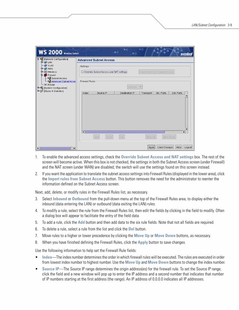
LAN/Subnet Configuration 3-9
1. To enable the advanced access settings, check the Override Subnet Access and NAT settings box. The rest of the screen will become active. When this box is not checked, the settings in both the Subnet Access screen (under Firewall) and the NAT screen (under WAN) are disabled; the switch will use the settings found on this screen instead.
2. If you want the application to translate the subnet access settings into Firewall Rules (displayed in the lower area), click the Import rules from Subnet Access button. This button removes the need for the administrator to reenter the information defined on the Subnet Access screen.
Next, add, delete, or modify rules in the Firewall Rules list, as necessary.
3. Select Inbound or Outbound from the pull-down menu at the top of the Firewall Rules area, to display either the inbound (data entering the LAN) or outbound (data exiting the LAN) rules.
4. To modify a rule, select the rule from the Firewall Rules list, then edit the fields by clicking in the field to modify. Often a dialog box will appear to facilitate the entry of the field data.
5. To add a rule, click the Add button and then add data to the six rule fields. Note that not all fields are required.
6. To delete a rule, select a rule from the list and click the Del button.
7. Move rules to a higher or lower precedence by clicking the Move Up or Move Down buttons, as necessary.
8. When you have finished defining the Firewall Rules, click the Apply button to save changes.
Use the following information to help set the Firewall Rule fields:
• Index—The index number determines the order in which firewall rules will be executed. The rules are executed in order from lowest index number to highest number. Use the Move Up and Move Down buttons to change the index number.
• Source IP—The Source IP range determines the origin address(es) for the firewall rule. To set the Source IP range, click the field and a new window will pop up to enter the IP address and a second number that indicates that number of IP numbers starting at the first address (the range). An IP address of 0.0.0.0 indicates all IP addresses.
WS 2000 Wireless Switch System Reference Guide3-10
• Destination IP—The Destination IP range determines the target address(es) for the firewall rule. To configure the Destination IP range, click the field and a new window will pop up to enter the IP address and range. An IP address of 0.0.0.0 indicates all IP addresses.
• Transport—To determine the transport protocol to be filtered in the firewall rule, click the field to choose from the list of protocols:
• Src. Ports (Source Ports)—The source port range determines which ports the firewall rule applies to on the source IP address. To configure the source port range, click the field and a new window will pop up to enter the starting and ending ports in the range. For rules where only a single port is necessary, enter the same port in the start and end port fields.
• Dst. Ports (Destination Ports)—The destination port range determines which ports the firewall rule applies to on the destination IP address. To configure the destination port range, click the field and a new window will pop up to enter the starting and ending ports in the range. For rules where only a single port is necessary, enter the same port in the start and end port fields.
Transport DescriptionALL This selection designates all of the protocols displayed in the table’s pull-down menu, as described
below.
TCP Transmission Control Protocol (TCP) is a set of rules used with Internet Protocol (IP) to send data as message units over the Internet. While IP handles the actual delivery of data, TCP keeps track of individual units of data called packets. Messages are divided into packets for efficient routing through the Internet.
UDP User Datagram Protocol (UDP) is mostly used for broadcasting data over the Internet. Like TCP, UDP runs on top of Internet Protocol (IP) networks. Unlike TCP/IP, UDP/IP provides very few error recovery services and methods. UDP offers a way to directly connect, and then send and receive datagrams over an IP network.
ICMP Internet Control Message Protocol (ICMP) is tightly integrated with IP. ICMP messages, delivered in IP packets, are used for out-of-band messages related to network operation. Because ICMP uses IP, ICMP packet delivery is unreliable. Hosts cannot count on receiving ICMP packets for a network problem.
AH Authentication Header (AH) is one of the two key components of IP Security Protocol (IPSec). The other key component is Encapsulating Security Protocol (ESP), described below.AH provides authentication, proving the packet sender really is the sender, and the data really is the data sent. AH can be used in transport mode, providing security between two end points. Also, AH can be used in tunnel mode, providing security like that of a Virtual Private Network (VPN).
ESP Encapsulating Security Protocol (ESP) is one of the two key components of IP Security Protocol (IPSec). The other key component is Authentication Header (AH), described above.ESP encrypts the payload of packets, and also provides authentication services. ESP can be used in transport mode, providing security between two end points. Also, ESP can be used in tunnel mode, providing security like that of a Virtual Private Network (VPN).
GRE General Routing Encapsulation (GRE) supports VPNs across the Internet. GRE is a mechanism for encapsulating network layer protocols over any other network layer protocol. Such encapsulation allows routing of IP packets between private IP networks across an Internet that uses globally assigned IP addresses.
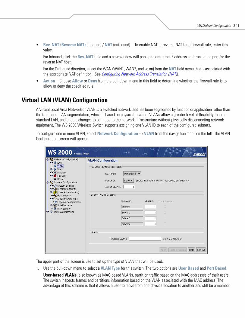
LAN/Subnet Configuration 3-11
• Rev. NAT (Reverse NAT) (inbound) / NAT (outbound)—To enable NAT or reverse NAT for a firewall rule, enter this value.
For Inbound, click the Rev. NAT field and a new window will pop up to enter the IP address and translation port for the reverse NAT host.
For the Outbound direction, select the WAN (WAN1, WAN2, and so on) from the NAT field menu that is associated with the appropriate NAT definition. (See Configuring Network Address Translation (NAT)).
• Action—Choose Allow or Deny from the pull-down menu in this field to determine whether the firewall rule is to allow or deny the specified rule.
Virtual LAN (VLAN) ConfigurationA Virtual Local Area Network or VLAN is a switched network that has been segmented by function or application rather than the traditional LAN segmentation, which is based on physical location. VLANs allow a greater level of flexibility than a standard LAN, and enable changes to be made to the network infrastructure without physically disconnecting network equipment. The WS 2000 Wireless Switch supports assigning one VLAN ID to each of the configured subnets.
To configure one or more VLAN, select Network Configuration --> VLAN from the navigation menu on the left. The VLAN Configuration screen will appear.
The upper part of the screen is use to set up the type of VLAN that will be used.
1. Use the pull-down menu to select a VLAN Type for this switch. The two options are User Based and Port Based.
User-based VLANs, also known as MAC-based VLANs, partition traffic based on the MAC addresses of their users. The switch inspects frames and partitions information based on the VLAN associated with the MAC address. The advantage of this scheme is that it allows a user to move from one physical location to another and still be a member
WS 2000 Wireless Switch System Reference Guide3-12
of the same VLAN. The disadvantage of user-based VLANs is that each client's MAC address must be specified, which can be very time consuming for large network deployments.
Port-based VLANs, also known as Layer 3 VLANs, partition traffic based on protocol. The switch inspects each packet, extracts the VLAN membership information, and partitions the packet accordingly. The advantage of this scheme is that it allows partitioning based on protocol type, and each user does not have to be manually added to the VLAN. The disadvantage of port-based VLANs is that network performance is generally slower than user-based VLANs. This performance loss is due to the large amount of overhead required to inspect each packet for the VLAN ID.
2. Use the pull-down menu to select a Trunk Port for the switch. Any one of the switch's six ports that is not associated with a subnet can be configured as the Trunk Port for a user-based VLAN.
A Trunk Port allows a type of VLAN partitioning that is transparent to the users connected to that port. All traffic passing through the Trunk Port is tagged with the default VLAN ID tag.
Ports that are associated with a subnet are not available in the Trunk Port pull-down menu. To disassociate a port from a subnet (so that is can be assigned as the trunk port), go to the appropriate subnet on the menu, select the desired port, and then click Delete. After clicking the Apply button on the subnet screen, return to the VLAN page, and the port will be available in the Trunk Port pull-down menu.
3. Enter a VLAN Tag between 1 and 31. This tag will be associated with all VLAN traffic that goes out through the Trunk Port in a user-based VLAN. This tag should be the one used to share information between the various VLANs. This value should also be either one of the user-based or port-based VLANs.
The next step is to specify the mapping between the available subnets and the VLANs that you are defining. In the mapping table, each of the four subnets are listed by name; however, only subnets that are currently active can be configured with a VLAN ID.
4. Enter the VLAN ID value for each subnet. The value must be between 1 and 31. The WS 2000 Wireless Switch only supports VLANs numbered between 1 and 31 in user-based VLANs. If your network uses a VLAN number higher than 31, you will not be able to use VLAN trunking with this switch.
5. In the Trunked VLANs field, enter in the VLAN IDs for VLANs that you wish to configure as trunked VLANs. When entering multiple VLAN IDs, separate each ID with a comma. To qualify as a trunked VLAN, the VLAN ID must be associated with a configured subnet.
The Trunk Enable box will be automatically checked on subnets for which VLAN IDs have been selected as trunked VLANs.
6. Click the Apply button to save changes.
4WAN Configuration
Configuring the WAN Interface . . . . . . . . . . . . . . . . . . . . . . . . . . . . . . . . . . . . . . . . . . . . . . . . . . . . . . . . . . . . . . 4-2Communicating with the Outside World . . . . . . . . . . . . . . . . . . . . . . . . . . . . . . . . . . . . . . . . . . . . . . . . . . . 4-2Setting Up Point-to-Point over Ethernet (PPPoE) Communication . . . . . . . . . . . . . . . . . . . . . . . . . . . . . . . . 4-3
Configuring the WS 2000 Firewall . . . . . . . . . . . . . . . . . . . . . . . . . . . . . . . . . . . . . . . . . . . . . . . . . . . . . . . . . . . . 4-4Disabling the Firewall . . . . . . . . . . . . . . . . . . . . . . . . . . . . . . . . . . . . . . . . . . . . . . . . . . . . . . . . . . . . . . . . . 4-4Setting the NAT Timeout . . . . . . . . . . . . . . . . . . . . . . . . . . . . . . . . . . . . . . . . . . . . . . . . . . . . . . . . . . . . . . . 4-4Configurable Firewall Filters . . . . . . . . . . . . . . . . . . . . . . . . . . . . . . . . . . . . . . . . . . . . . . . . . . . . . . . . . . . . 4-4
Configuring Content Filtering . . . . . . . . . . . . . . . . . . . . . . . . . . . . . . . . . . . . . . . . . . . . . . . . . . . . . . . . . . . . . . . . 4-6Configuring Network Address Translation (NAT) . . . . . . . . . . . . . . . . . . . . . . . . . . . . . . . . . . . . . . . . . . . . . . . . 4-7Configuring Static Routes . . . . . . . . . . . . . . . . . . . . . . . . . . . . . . . . . . . . . . . . . . . . . . . . . . . . . . . . . . . . . . . . . 4-10
Creating User-Defined Routes . . . . . . . . . . . . . . . . . . . . . . . . . . . . . . . . . . . . . . . . . . . . . . . . . . . . . . . . . . 4-10Setting the RIP Configuration . . . . . . . . . . . . . . . . . . . . . . . . . . . . . . . . . . . . . . . . . . . . . . . . . . . . . . . . . . 4-11
Configuring a Virtual Private Network (VPN) . . . . . . . . . . . . . . . . . . . . . . . . . . . . . . . . . . . . . . . . . . . . . . . . . . . 4-12Creating a VPN Tunnel . . . . . . . . . . . . . . . . . . . . . . . . . . . . . . . . . . . . . . . . . . . . . . . . . . . . . . . . . . . . . . . . 4-14Setting Up VPN Security . . . . . . . . . . . . . . . . . . . . . . . . . . . . . . . . . . . . . . . . . . . . . . . . . . . . . . . . . . . . . . 4-14Configuring Manual Key Exchange . . . . . . . . . . . . . . . . . . . . . . . . . . . . . . . . . . . . . . . . . . . . . . . . . . . . . . 4-15Setting Up Automatic Key Exchange . . . . . . . . . . . . . . . . . . . . . . . . . . . . . . . . . . . . . . . . . . . . . . . . . . . . . 4-17Setting Up Internet Key Exchange (IKE) . . . . . . . . . . . . . . . . . . . . . . . . . . . . . . . . . . . . . . . . . . . . . . . . . . 4-18VPN—Frequently Asked Questions . . . . . . . . . . . . . . . . . . . . . . . . . . . . . . . . . . . . . . . . . . . . . . . . . . . . . . 4-20
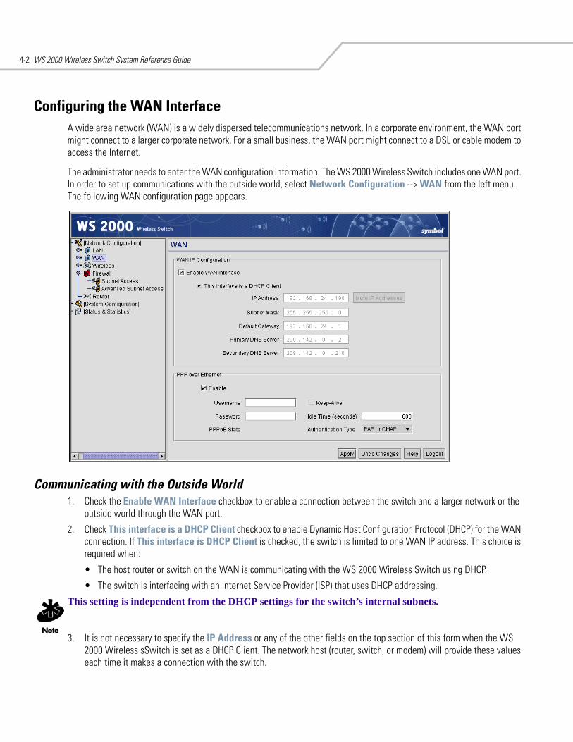
WS 2000 Wireless Switch System Reference Guide4-2
Configuring the WAN InterfaceA wide area network (WAN) is a widely dispersed telecommunications network. In a corporate environment, the WAN port might connect to a larger corporate network. For a small business, the WAN port might connect to a DSL or cable modem to access the Internet.
The administrator needs to enter the WAN configuration information. The WS 2000 Wireless Switch includes one WAN port. In order to set up communications with the outside world, select Network Configuration --> WAN from the left menu. The following WAN configuration page appears.
Communicating with the Outside World1. Check the Enable WAN Interface checkbox to enable a connection between the switch and a larger network or the
outside world through the WAN port.
2. Check This interface is a DHCP Client checkbox to enable Dynamic Host Configuration Protocol (DHCP) for the WAN connection. If This interface is DHCP Client is checked, the switch is limited to one WAN IP address. This choice is required when:
• The host router or switch on the WAN is communicating with the WS 2000 Wireless Switch using DHCP.
• The switch is interfacing with an Internet Service Provider (ISP) that uses DHCP addressing.
This setting is independent from the DHCP settings for the switch’s internal subnets.
3. It is not necessary to specify the IP Address or any of the other fields on the top section of this form when the WS 2000 Wireless sSwitch is set as a DHCP Client. The network host (router, switch, or modem) will provide these values each time it makes a connection with the switch.
WAN Configuration 4-3
4. If the DHCP setting is not checked, fill in the information in this area. To find out the information to enter into these fields, contact the network administrator or the ISP that provided the cable modem or DSL router. All the fields below take standard IP addresses of the form xxx.xxx.xxx.xxx.
• The IP Address refers to the IP address that the outside world will use to address the WS 2000 Wireless Switch.
• Click the More IP Addresses button to specify additional static IP addresses for the switch. Additional IP addresses are required when users within the LAN need dedicated IP addresses, or when servers in the LAN need to be accessed (addressed) by the outside world. The pop-up window allows the administrator to enter up to eight WAN IP addresses for the switch.
• The Subnet Mask is the mask used for the WAN.
• The Default Gateway is the address of the device that provides the connection to the WAN (often a cable modem or DSL router).
• The two DNS Server fields specify DNS addresses of servers that can translate domain names, such as www.symbol.com, into IP addresses that the network uses when passing information. The Secondary DNS Server acts as a backup to the Primary DNS Server, when the primary server is not responding.
Setting Up Point-to-Point over Ethernet (PPPoE) CommunicationPPPoE provides the ability to connect a network of hosts through a simple device to a remote access concentrator. Many DSL providers require that their clients communicate using this protocol. The facility allows the ISP to control access, billing, and type of service provided to clients on a per-user or per-site basis. Check with the network administrator or ISP to determine whether to enable this feature, and, if so, find out the username and password required for authentication.
1. Check Enable in the PPP over Ethernet area to enable the PPPoE protocol for high-speed connections.
2. Enter the Username and Password required for authentication. The username and password is for the switch’s router to use when connecting to the ISP. When the Internet session starts, the ISP authenticates the username.
3. Set the Idle Time to an appropriate number. This number is the amount of time the PPPoE connection will be idle before it disconnects. The 10000 second (default idle time is appropriate for most situations).
4. Check Keep Alive to instruct the switch to continue occasional communications over the WAN even when client communications to the WAN are idle. Some ISPs terminate inactive connections, while others do not. In either case, enabling Keep-Alive mode keeps the switch’s WAN connection alive, even when there is no traffic. If the ISP drops the connection after so much idle time, the switch automatically reestablishes the connection to the ISP.
5. Select the appropriate WAN authentication method from the drop-down menu. Collect this information from the network administrator. Select between None, PAP, CHAP, or PAP or CHAP.
6. Click the Apply button to save changes.
CHAP A type of authentication in which the person logging in uses secret information and some special math-ematical operations to come up with a number value. The server he or she is logging into knows the same secret value and performs the same mathematical operations. If the results match, the person is authorized to access the server. One of the numbers in the mathematical operation is changed after every login, to protect against an intruder secretly copying a valid authentication session and replaying it later to log in.
PAP An identity verification method used to send a user name and password over a network to a computer that compares the user name and password to a table listing authorized users. This method of authen-tication is less secure, because the user name and password travel as clear text that a hacker could read.
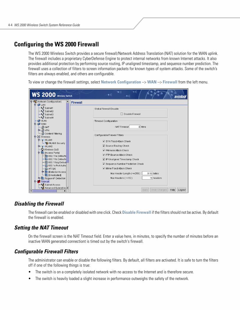
WS 2000 Wireless Switch System Reference Guide4-4
Configuring the WS 2000 FirewallThe WS 2000 Wireless Switch provides a secure firewall/Network Address Translation (NAT) solution for the WAN uplink. The firewall includes a proprietary CyberDefense Engine to protect internal networks from known Internet attacks. It also provides additional protection by performing source routing, IP unaligned timestamp, and sequence number prediction. The firewall uses a collection of filters to screen information packets for known types of system attacks. Some of the switch’s filters are always enabled, and others are configurable.
To view or change the firewall settings, select Network Configuration --> WAN --> Firewall from the left menu.
Disabling the FirewallThe firewall can be enabled or disabled with one click. Check Disable Firewall if the filters should not be active. By default the firewall is enabled.
Setting the NAT TimeoutOn the firewall screen is the NAT Timeout field. Enter a value here, in minutes, to specify the number of minutes before an inactive WAN generated connectiont is timed out by the switch's firewall.
Configurable Firewall Filters The administrator can enable or disable the following filters. By default, all filters are activated. It is safe to turn the filters off if one of the following things is true:
• The switch is on a completely isolated network with no access to the Internet and is therefore secure.
• The switch is heavily loaded a slight increase in performance outweighs the safety of the network.
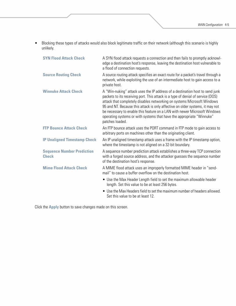
WAN Configuration 4-5
• Blocking these types of attacks would also block legitimate traffic on their network (although this scenario is highly unlikely.
Click the Apply button to save changes made on this screen.
SYN Flood Attack Check A SYN flood attack requests a connection and then fails to promptly acknowl-edge a destination host’s response, leaving the destination host vulnerable to a flood of connection requests.
Source Routing Check A source routing attack specifies an exact route for a packet’s travel through a network, while exploiting the use of an intermediate host to gain access to a private host.
Winnuke Attack Check A “Win-nuking” attack uses the IP address of a destination host to send junk packets to its receiving port. This attack is a type of denial of service (DOS) attack that completely disables networking on systems Microsoft Windows 95 and NT. Because this attack is only affective on older systems, it may not be necessary to enable this feature on a LAN with newer Microsoft Windows operating systems or with systems that have the appropriate “Winnuke” patches loaded.
FTP Bounce Attack Check An FTP bounce attack uses the PORT command in FTP mode to gain access to arbitrary ports on machines other than the originating client.
IP Unaligned Timestamp Check An IP unaligned timestamp attack uses a frame with the IP timestamp option, where the timestamp is not aligned on a 32-bit boundary.
Sequence Number Prediction Check
A sequence number prediction attack establishes a three-way TCP connection with a forged source address, and the attacker guesses the sequence number of the destination host’s response.
Mime Flood Attack Check A MIME flood attack uses an improperly formatted MIME header in “send-mail” to cause a buffer overflow on the destination host.
• Use the Max Header Length field to set the maximum allowable header length. Set this value to be at least 256 bytes.
• Use the Max Headers field to set the maximum number of headers allowed. Set this value to be at least 12.
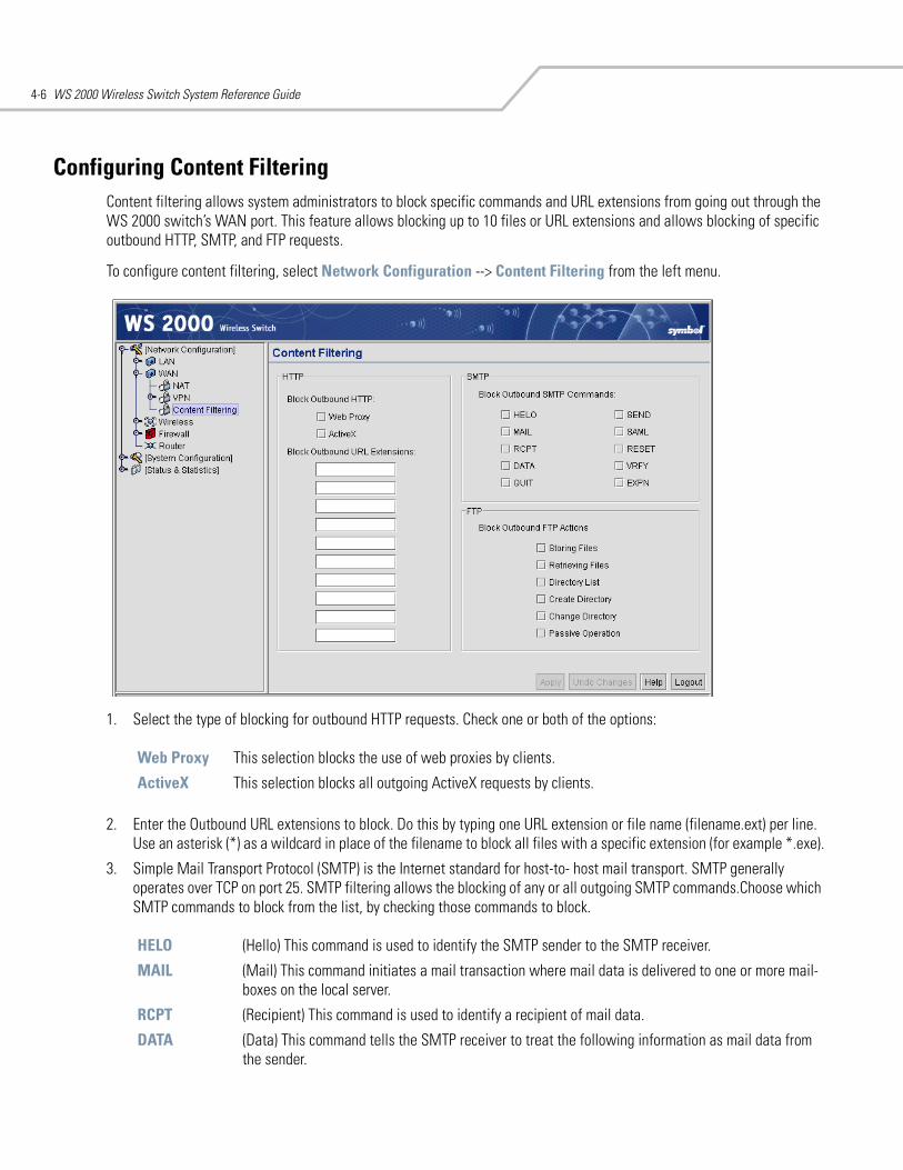
WS 2000 Wireless Switch System Reference Guide4-6
Configuring Content FilteringContent filtering allows system administrators to block specific commands and URL extensions from going out through the WS 2000 switch’s WAN port. This feature allows blocking up to 10 files or URL extensions and allows blocking of specific outbound HTTP, SMTP, and FTP requests.
To configure content filtering, select Network Configuration --> Content Filtering from the left menu.
1. Select the type of blocking for outbound HTTP requests. Check one or both of the options:
2. Enter the Outbound URL extensions to block. Do this by typing one URL extension or file name (filename.ext) per line. Use an asterisk (*) as a wildcard in place of the filename to block all files with a specific extension (for example *.exe).
3. Simple Mail Transport Protocol (SMTP) is the Internet standard for host-to- host mail transport. SMTP generally operates over TCP on port 25. SMTP filtering allows the blocking of any or all outgoing SMTP commands.Choose which SMTP commands to block from the list, by checking those commands to block.
Web Proxy This selection blocks the use of web proxies by clients.
ActiveX This selection blocks all outgoing ActiveX requests by clients.
HELO (Hello) This command is used to identify the SMTP sender to the SMTP receiver.
MAIL (Mail) This command initiates a mail transaction where mail data is delivered to one or more mail-boxes on the local server.
RCPT (Recipient) This command is used to identify a recipient of mail data.
DATA (Data) This command tells the SMTP receiver to treat the following information as mail data from the sender.
WAN Configuration 4-7
4. Specify the outbound FTP actions that should get blocked by checking the FTP action to block. File Transfer Protocol (FTP) is the Internet standard for host-to-host mail transport. FTP generally operates over TCP on port 21.
5. Click the Apply button to save changes made on this screen.
Configuring Network Address Translation (NAT)NAT provides the translation of an Internet Protocol (IP) address within one network to a different, known IP address within another network. One network is designated the private network, while the other is the public. NAT provides a layer of security by translating private (local) network addresses to one or more public IP addresses. For example, when an administrator wants to allow individuals on the WAN side access to a particular FTP or web server that is located on one of the LAN subnets but does not want to permit any other access, NAT is the appropriate solution.
1. Select Network Configuration --> WAN --> NAT from the left menu. The following screen appears.
QUIT (Quit) This command tells the receiver to respond with an OK reply and then terminate communica-tion with the sender.
SEND (Send) This command initiates a mail transaction where mail is sent to one or more remote termi-nals.
SAML (Send and Mail) This command initiates a mail transaction where mail data is sent to one or more local mailboxes and remote terminals.
RESET (Reset) This command cancels the current mail transaction and informs the recipient to discard any data sent during this transaction.
VRFY (Verify) This command asks the receiver to confirm that the specified argument identifies a user. If the argument does identify a user the full name and fully qualified mailbox is returned.
EXPN (Expand) This command asks the receiver to confirm that a specified argument identifies a mailing list. If the argument does identify a mailing list the membership list of that mailing list is returned.
Storing Files Blocks the request to transfer files sent from the client across the switch’s WAN port to the FTP server.
Retrieving Files Blocks the request to retrieve files sent from the FTP server across the switch’s WAN port to the client.
Directory List Blocks requests to retrieve a directory listing sent from the client across the switch’s WAN port to the FTP server.
Create Directory Blocks requests to create directories sent from the client across the switch’s WAN port to the FTP server.
Change Directory Blocks requests to change directories sent from the client across the switch’s WAN port to the FTP server.
Passive Operation Blocks passive mode FTP requests sent from the client across the switch’s WAN port to the FTP server.
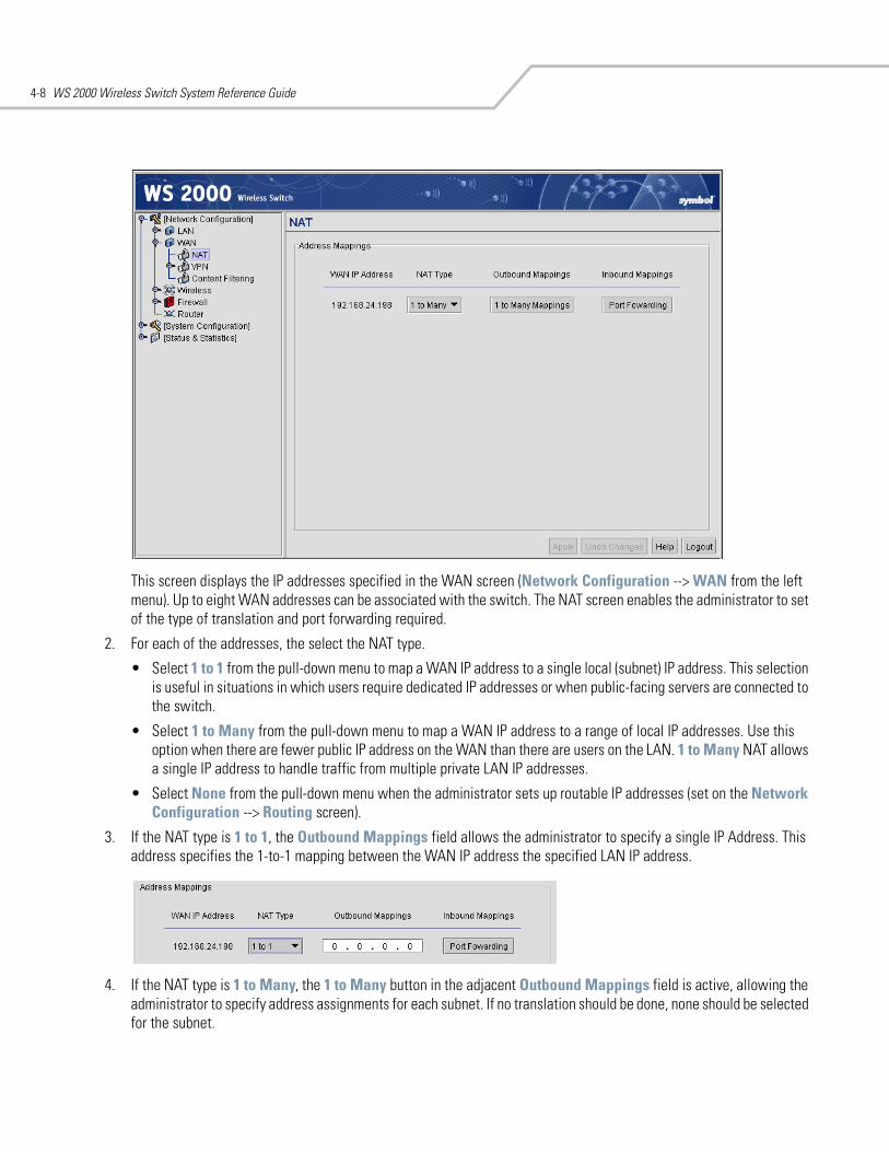
WS 2000 Wireless Switch System Reference Guide4-8
This screen displays the IP addresses specified in the WAN screen (Network Configuration --> WAN from the left menu). Up to eight WAN addresses can be associated with the switch. The NAT screen enables the administrator to set of the type of translation and port forwarding required.
2. For each of the addresses, the select the NAT type.
• Select 1 to 1 from the pull-down menu to map a WAN IP address to a single local (subnet) IP address. This selection is useful in situations in which users require dedicated IP addresses or when public-facing servers are connected to the switch.
• Select 1 to Many from the pull-down menu to map a WAN IP address to a range of local IP addresses. Use this option when there are fewer public IP address on the WAN than there are users on the LAN. 1 to Many NAT allows a single IP address to handle traffic from multiple private LAN IP addresses.
• Select None from the pull-down menu when the administrator sets up routable IP addresses (set on the Network Configuration --> Routing screen).
3. If the NAT type is 1 to 1, the Outbound Mappings field allows the administrator to specify a single IP Address. This address specifies the 1-to-1 mapping between the WAN IP address the specified LAN IP address.
4. If the NAT type is 1 to Many, the 1 to Many button in the adjacent Outbound Mappings field is active, allowing the administrator to specify address assignments for each subnet. If no translation should be done, none should be selected for the subnet.
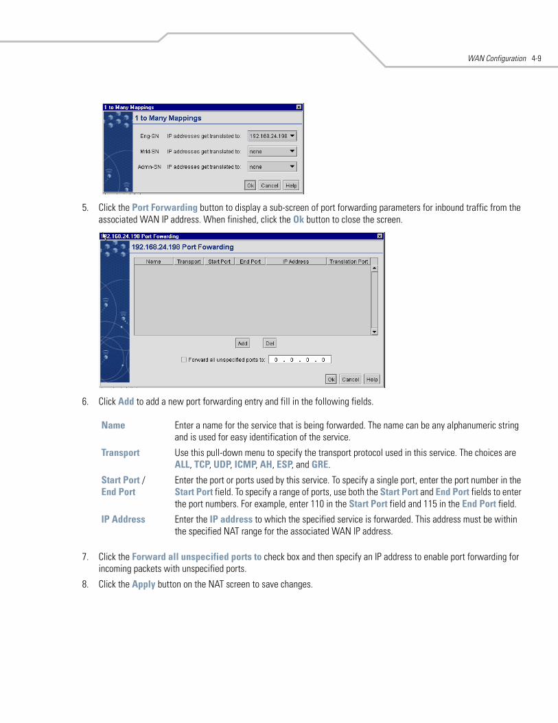
WAN Configuration 4-9
5. Click the Port Forwarding button to display a sub-screen of port forwarding parameters for inbound traffic from the associated WAN IP address. When finished, click the Ok button to close the screen.
6. Click Add to add a new port forwarding entry and fill in the following fields.
7. Click the Forward all unspecified ports to check box and then specify an IP address to enable port forwarding for incoming packets with unspecified ports.
8. Click the Apply button on the NAT screen to save changes.
Name Enter a name for the service that is being forwarded. The name can be any alphanumeric string and is used for easy identification of the service.
Transport Use this pull-down menu to specify the transport protocol used in this service. The choices are ALL, TCP, UDP, ICMP, AH, ESP, and GRE.
Start Port / End Port
Enter the port or ports used by this service. To specify a single port, enter the port number in the Start Port field. To specify a range of ports, use both the Start Port and End Port fields to enter the port numbers. For example, enter 110 in the Start Port field and 115 in the End Port field.
IP Address Enter the IP address to which the specified service is forwarded. This address must be within the specified NAT range for the associated WAN IP address.

WS 2000 Wireless Switch System Reference Guide4-10
Configuring Static RoutesA router uses routing tables and protocols to forward data packets from one network to another. The switch’s router manages traffic within the switch’s network, and directs traffic from the WAN to destinations on the switch-managed LAN. The WS 2000 Network Management System provides the Router screen to view and set the router’s connected routes. To view this screen, select Network Configuration --> Router from the menu on the left.
The WS 2000 Route Table area of the screen displays a list of currently connected routes between the enabled subnets, the WAN, and the router. The information here is generated from settings applied on the Subnet and WAN screens. The destination for each subnet is its IP address. The subnet mask (or network mask) and gateway settings are those belonging to each subnet, or to the WAN in general. To make changes to the information in the Connected Routes information, go to the appropriate subnet screen (LAN --> <subnet name> or the WAN screen (WAN)).
Creating User Defined RoutesThe User Defined Routes area of the screen allows the administrator to view, add or delete internal static (dedicated) routes, and to enable or disable routes that are generated using the Routing Information Protocol (RIP). If RIP is enabled, this table can also include routes that RIP generates.
This table also includes internal static routes that the administrator adds. Internal static routes are dedicated routes for data that travels from the WAN, through the switch, and to a specified subnet. Such routes are supplemental to the default routes already set up for each of the subnets.
1. Click the Add button to create a new table entry.
2. Specify the destination IP address, subnet mask, and gateway information for the internal static route.
3. Select an enabled subnet from the Interface column’s drop-down menu to complete the table entry. Information in the Metric column is automatically generated, and is used by router protocols to determine the best hop routes.
4. The Source column automatically displays “User” for a user-added entry. An RIP-sourced entry displays “RIP.”
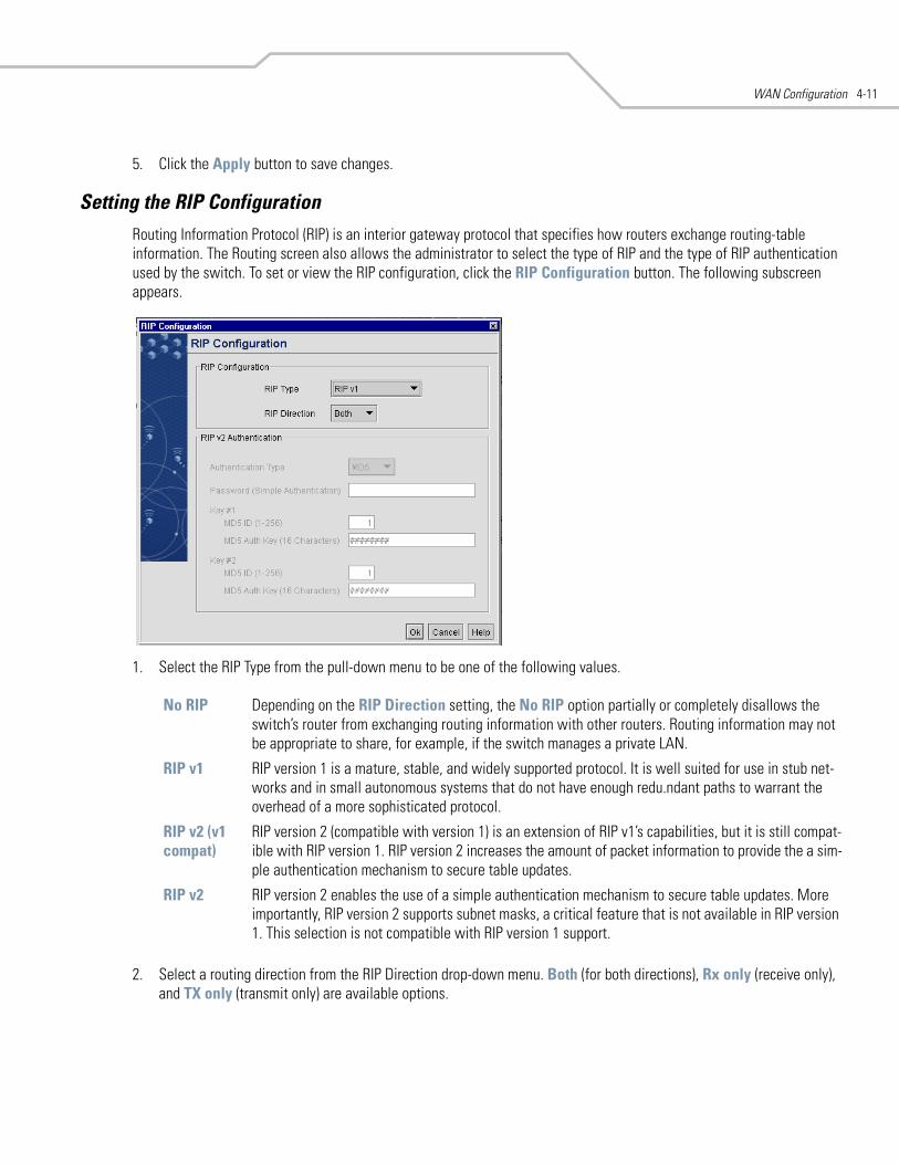
WAN Configuration 4-11
5. Click the Apply button to save changes.
Setting the RIP ConfigurationRouting Information Protocol (RIP) is an interior gateway protocol that specifies how routers exchange routing-table information. The Routing screen also allows the administrator to select the type of RIP and the type of RIP authentication used by the switch. To set or view the RIP configuration, click the RIP Configuration button. The following subscreen appears.
1. Select the RIP Type from the pull-down menu to be one of the following values.
2. Select a routing direction from the RIP Direction drop-down menu. Both (for both directions), Rx only (receive only), and TX only (transmit only) are available options.
No RIP Depending on the RIP Direction setting, the No RIP option partially or completely disallows the switch’s router from exchanging routing information with other routers. Routing information may not be appropriate to share, for example, if the switch manages a private LAN.
RIP v1 RIP version 1 is a mature, stable, and widely supported protocol. It is well suited for use in stub net-works and in small autonomous systems that do not have enough redu.ndant paths to warrant the overhead of a more sophisticated protocol.
RIP v2 (v1 compat)
RIP version 2 (compatible with version 1) is an extension of RIP v1’s capabilities, but it is still compat-ible with RIP version 1. RIP version 2 increases the amount of packet information to provide the a sim-ple authentication mechanism to secure table updates.
RIP v2 RIP version 2 enables the use of a simple authentication mechanism to secure table updates. More importantly, RIP version 2 supports subnet masks, a critical feature that is not available in RIP version 1. This selection is not compatible with RIP version 1 support.
WS 2000 Wireless Switch System Reference Guide4-12
3. If RIP v2 or RIP v2 (v1 compat) is the selected RIP type, the RIP v2 Authentication area of the screen becomes active. Select the type of authentication to use from the Authentication Type drop-down menu. Available options are:
4. If the Simple authentication method is selected, specify a password of up to 15 alphanumeric characters in the Password (Simple Authentication) field.
5. If the MD5 authentication method is selected, fill in the Key #1 and Key #2 fields. Type in any numeric value between 0 and 256 into the MD5 ID field. Type in any string consisting of 16 alphanumeric characters into the MD5 Auth Key field.
6. Click the Ok button to return to the Routing screen.
Configuring a Virtual Private Network (VPN)VPNs are IP-based networks that use encryption and tunneling to give users remote access to a secure LAN. In essence, the trust relationship is extended from one LAN across the public network to another LAN, without sacrificing security. A VPN behaves similarly to a private network; however, because the data travels through the public network, three types of security mechanisms are required: confidentiality, integrity, and authentication.
• Confidentiality (through public-key or secret-key cryptology) ensures the privacy of information being exchanged between communicating parties.
• Integrity ensures that information being transmitted over the public Internet is not altered in any way during transit (by using hash codes, message authentication codes, or digital signatures).
• Authentication (with password authentication or digital signatures) ensures the identity of all communicating parties.
A diagram of a typical VPN situation is shown below, where there is a VPN tunnel created between two WS 2000 switches across the WAN. The diagram shows the settings for both switches.
None This option disables the RIP authentication.
Simple This option enable RIP version 2’s simple authentication mechanism.This setting activates the Password (Simple Authentication) field.
MD5 This option enables the MD5 algorithm for data verification. MD5 takes as input a message of arbi-trary length and produces a 128-bit fingerprint. The MD5 algorithm is intended for digital signature applications, in which a large file must be compressed in a secure manner before being encrypted with a private (secret) key under a public-key cryptographic system. The MD5 setting activates the RIP v2 Authentication settings for keys (below).
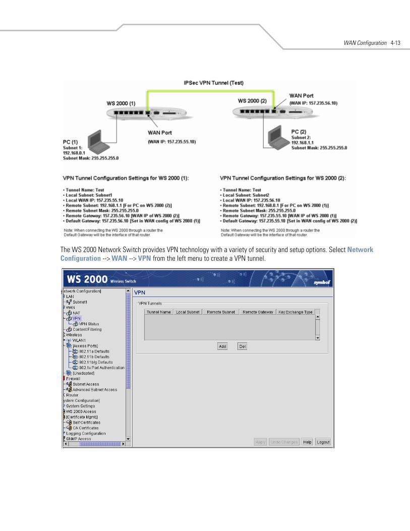
WAN Configuration 4-13
The WS 2000 Network Switch provides VPN technology with a variety of security and setup options. Select Network Configuration --> WAN --> VPN from the left menu to create a VPN tunnel.
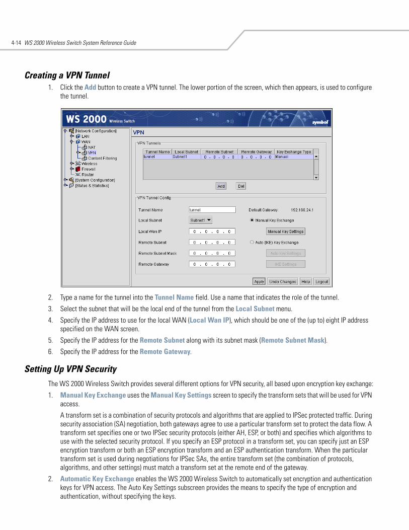
WS 2000 Wireless Switch System Reference Guide4-14
Creating a VPN Tunnel 1. Click the Add button to create a VPN tunnel. The lower portion of the screen, which then appears, is used to configure
the tunnel.
2. Type a name for the tunnel into the Tunnel Name field. Use a name that indicates the role of the tunnel.
3. Select the subnet that will be the local end of the tunnel from the Local Subnet menu.
4. Specify the IP address to use for the local WAN (Local Wan IP), which should be one of the (up to) eight IP address specified on the WAN screen.
5. Specify the IP address for the Remote Subnet along with its subnet mask (Remote Subnet Mask).
6. Specify the IP address for the Remote Gateway.
Setting Up VPN SecurityThe WS 2000 Wireless Switch provides several different options for VPN security, all based upon encryption key exchange:
1. Manual Key Exchange uses the Manual Key Settings screen to specify the transform sets that will be used for VPN access.
A transform set is a combination of security protocols and algorithms that are applied to IPSec protected traffic. During security association (SA) negotiation, both gateways agree to use a particular transform set to protect the data flow. A transform set specifies one or two IPSec security protocols (either AH, ESP, or both) and specifies which algorithms to use with the selected security protocol. If you specify an ESP protocol in a transform set, you can specify just an ESP encryption transform or both an ESP encryption transform and an ESP authentication transform. When the particular transform set is used during negotiations for IPSec SAs, the entire transform set (the combination of protocols, algorithms, and other settings) must match a transform set at the remote end of the gateway.
2. Automatic Key Exchange enables the WS 2000 Wireless Switch to automatically set encryption and authentication keys for VPN access. The Auto Key Settings subscreen provides the means to specify the type of encryption and authentication, without specifying the keys.
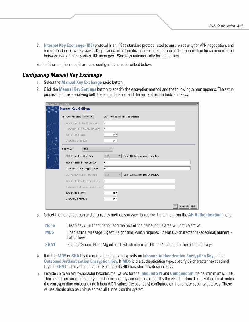
WAN Configuration 4-15
3. Internet Key Exchange (IKE) protocol is an IPSec standard protocol used to ensure security for VPN negotiation, and remote host or network access. IKE provides an automatic means of negotiation and authentication for communication between two or more parties. IKE manages IPSec keys automatically for the parties.
Each of these options requires some configuration, as described below.
Configuring Manual Key Exchange 1. Select the Manual Key Exchange radio button.
2. Click the Manual Key Settings button to specify the encryption method and the following screen appears. The setup process requires specifying both the authentication and the encryption methods and keys.
3. Select the authentication and anti-replay method you wish to use for the tunnel from the AH Authentication menu.
4. If either MD5 or SHA1 is the authentication type, specify an Inbound Authentication Encryption Key and an Outbound Authentication Encryption Key. If MD5 is the authentication type, specify 32-character hexadecimal keys. If SHA1 is the authentication type, specify 40-character hexadecimal keys.
5. Provide up to an eight-character hexadecimal values for the Inbound SPI and Outbound SPI fields (minimum is 100). These fields are used to identify the inbound security association created by the AH algorithm. These values must match the corresponding outbound and inbound SPI values (respectively) configured on the remote security gateway. These values should also be unique across all tunnels on the system.
None Disables AH authentication and the rest of the fields in this area will not be active.
MD5 Enables the Message Digest 5 algorithm, which requires 128-bit (32-character hexadecimal) authenti-cation keys.
SHA1 Enables Secure Hash Algorithm 1, which requires 160-bit (40-character hexadecimal) keys.
WS 2000 Wireless Switch System Reference Guide4-16
6. Select the ESP Type from the menu.
7. If ESP or ESP with Authentication is enabled, select an Encryption Algorithm from the menu.
8. Provide keys for both Inbound ESP Encryption Key and Outbound ESP Encryption Key. The length of the keys is mandated by the selected encryption algorithm. These keys must match the opposite keys at the remote gateway. The outbound key here must match the inbound key at the remote gateway, and the inbound key here must match the outbound key at the remote gateway.
9. If ESP with Authentication is enabled, an authentication algorithm must be selected to be used with ESP from the ESP Authentication Algorithm menu.
10. If ESP with Authentication is enabled, specify both the Inbound and Outbound ESP Authentication Keys.
11. Provide two (up to) eight-character hexadecimal values used to identify the inbound and outbound security association created by the encryption algorithm. These values must match the reciprocal inbound/outbound SPI values configured on the remote security gateway, so the local inbound key must match the remote outbound key, and so on. This value should also be unique across all tunnels on the system.
12. Select Ok to return to the VPN screen.
None Disables ESP and the rest of the fields in this area will not be active.
ESP Enables Encapsulating Security Payload encryption for this tunnel.
ESP with Authentication
Enables Encapsulating Security Payload encryption with authentication for this tunnel.
DES This option selects the DES encryption algorithm, which requires 64-bit (16-character hexadecimal) keys.
3DES This option selects the 3DES encryption algorithm, which requires 192-bit (48-character hexadeci-mal) keys. When creating keys for 3DES, the first 8 bytes cannot equal the second 8 bytes, and the second 8 bytes cannot equal the third 8 bytes.
AES 128-bit This option selects the Advanced Encryption Standard algorithm in use with 128-bit (32-character hexadecimal) keys.
AES 192-bit This option selects the Advanced Encryption Standard algorithm in use with 192-bit (48-character hexadecimal) keys.
AES 256-bit This option selects the Advanced Encryption Standard algorithm in use with 256-bit (64-character hexadecimal) keys.
MD5 Enables the Message Digest 5 algorithm, which requires 128-bit (32-character hexadecimal) authentication keys.
SHA1 Enables Secure Hash Algorithm 1, which requires 160-bit (40-character hexadecimal) keys.
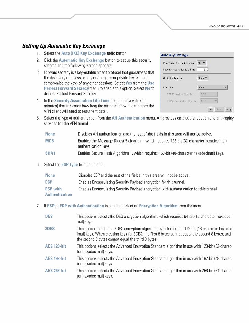
WAN Configuration 4-17
Setting Up Automatic Key Exchange1. Select the Auto (IKE) Key Exchange radio button.
2. Click the Automatic Key Exchange button to set up this security scheme and the following screen appears.
3. Forward secrecy is a key-establishment protocol that guarantees that the discovery of a session key or a long-term private key will not compromise the keys of any other sessions. Select Yes from the Use Perfect Forward Secrecy menu to enable this option. Select No to disable Perfect Forward Secrecy.
4. In the Security Association Life Time field, enter a value (in minutes) that indicates how long the association will last before the VPN client will need to reauthenticate .
5. Select the type of authentication from the AH Authentication menu. AH provides data authentication and anti-replay services for the VPN tunnel.
6. Select the ESP Type from the menu.
7. If ESP or ESP with Authentication is enabled, select an Encryption Algorithm from the menu.
None Disables AH authentication and the rest of the fields in this area will not be active.
MD5 Enables the Message Digest 5 algorithm, which requires 128-bit (32-character hexadecimal) authentication keys.
SHA1 Enables Secure Hash Algorithm 1, which requires 160-bit (40-character hexadecimal) keys.
None Disables ESP and the rest of the fields in this area will not be active.
ESP Enables Encapsulating Security Payload encryption for this tunnel.
ESP with Authentication
Enables Encapsulating Security Payload encryption with authentication for this tunnel.
DES This options selects the DES encryption algorithm, which requires 64-bit (16-character hexadeci-mal) keys.
3DES This option selects the 3DES encryption algorithm, which requires 192-bit (48-character hexadec-imal) keys. When creating keys for 3DES, the first 8 bytes cannot equal the second 8 bytes, and the second 8 bytes cannot equal the third 8 bytes.
AES 128-bit This options selects the Advanced Encryption Standard algorithm in use with 128-bit (32-charac-ter hexadecimal) keys.
AES 192-bit This options selects the Advanced Encryption Standard algorithm in use with 192-bit (48-charac-ter hexadecimal) keys.
AES 256-bit This options selects the Advanced Encryption Standard algorithm in use with 256-bit (64-charac-ter hexadecimal) keys.
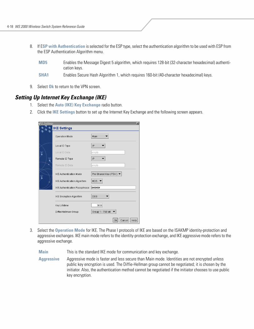
WS 2000 Wireless Switch System Reference Guide4-18
8. If ESP with Authentication is selected for the ESP type, select the authentication algorithm to be used with ESP from the ESP Authentication Algorithm menu.
9. Select Ok to return to the VPN screen.
Setting Up Internet Key Exchange (IKE) 1. Select the Auto (IKE) Key Exchange radio button.
2. Click the IKE Settings button to set up the Internet Key Exchange and the following screen appears.
3. Select the Operation Mode for IKE. The Phase I protocols of IKE are based on the ISAKMP identity-protection and aggressive exchanges. IKE main mode refers to the identity-protection exchange, and IKE aggressive mode refers to the aggressive exchange.
MD5 Enables the Message Digest 5 algorithm, which requires 128-bit (32-character hexadecimal) authenti-cation keys.
SHA1 Enables Secure Hash Algorithm 1, which requires 160-bit (40-character hexadecimal) keys.
Main This is the standard IKE mode for communication and key exchange.
Aggressive Aggressive mode is faster and less secure than Main mode. Identities are not encrypted unless public key encryption is used. The Diffie-Hellman group cannot be negotiated; it is chosen by the initiator. Also, the authentication method cannot be negotiated if the initiator chooses to use public key encryption.
WAN Configuration 4-19
4. Select the type of ID to be used for the WS 2000 end of the tunnel from the Remote ID Type menu.
5. If FQDN or UFQDN are selected, specify the data (either the qualified domain name or the user name) in the Local ID Data field.
6. Repeat steps 4 and 5 for the Remote ID Type and Remote ID Data fields.
7. Choose the authentication mode to be used with the IKE algorithm from the IKE Authentication Mode menu.
8. IKE provides data authentication and anti-replay services for the VPN tunnel. Select the desired authentication methods from the IKE Authentication Algorithm menu.
9. If Pre-Shared Key is the authentication mode, provide a key in the IKE Authentication Passphrase field. If MD5 is the selected authentication algorithm, provide a 32-character hexadecimal key. If SHA1 is the selected algorithm, provide a 40-character hexadecimal key.
10. Use the IKE Encryption Algorithm menu to select the encryption and authentication algorithms for this VPN tunnel.
11. Specify a Key Lifetime, which is the number of seconds that the key is valid. At the end of the lifetime, the key is renegotiated between the two parties.
IP Select this option if the local ID type is the IP address specified as part of the tunnel.
FQDN Select this item if the local ID type is a fully qualified domain name (such as sj.symbol.com). The set-ting for this field does not have to be fully qualified, it just must match the setting of the field for the Certificate Authority.
UFQDN Select this item if the local ID type is a user unqualified domain name (such as [email protected]). The setting for this field does not have to be unqualified, it just must match the setting of the field of the Certificate Authority.
Pre-shared key This option requires that you specify an authentication algorithm and passcode to be used during authentication.
RSA Certificates Select this option to use RSA certificates for authentication purposes. See Managing Digital Certificates to create and import certificates into the system.
MD5 Enables the Message Digest 5 algorithm, which requires 128-bit (32-character hexadecimal) authentication keys.
SHA1 Enables Secure Hash Algorithm 1, which requires 160-bit (40-character hexadecimal) keys.
DES This options selects the DES encryption algorithm, which requires 64-bit (16-character hexadeci-mal) keys.
3DES This option selects the 3DES encryption algorithm, which requires 192-bit (48-character hexadec-imal) keys. When creating keys for 3DES, the first 8 bytes cannot equal the second 8 bytes, and the second 8 bytes cannot equal the third 8 bytes.
AES 128-bit This options selects the Advanced Encryption Standard algorithm in use with 128-bit (32-charac-ter hexadecimal) keys.
AES 192-bit This options selects the Advanced Encryption Standard algorithm in use with 192-bit (48-charac-ter hexadecimal) keys.
AES 256-bit This options selects the Advanced Encryption Standard algorithm in use with 256-bit (64-charac-ter hexadecimal) keys.
WS 2000 Wireless Switch System Reference Guide4-20
12. Select the Diffie-Hellman Group to use. The Diffie-Hellman key agreement protocol allows two users to exchange a secret key over an insecure medium without any prior secrets. Two algorithms exist, one 768-bit and one 1024-bit algorithm.
13. Click the Ok button to return to the VPN screen.
VPN: Frequently Asked QuestionsDisclaimer: Using a VPN connection over the WAN interface is subject to the limitations of
your Internet Service Provider.
My tunnel works fine when I use the Subnet Access page to configure my firewall. Now that I use Advanced Subnet Access, my VPN no longer works. What am I doing wrong?
VPN requires certain packets to be passed through the firewall. Subnet Access automatically inserts these rules for you when you do VPN. Using Advanced Subnet Access requires the following rules to be in effect for each tunnel.
An allow inbound rule:
An allow outbound rule:
For IKE, an allow inbound rule:
Group 1 - 768 bit Somewhat faster than the 1024-bit algorithm, but secure enough in most situations.
Group 2 - 1024 bit Somewhat slower than the 768-bit algorithm, but much more secure and a better choice for extremely sensitive situations.
Src <Remote Subnet IP range>
Dst <Local Subnet IP range>
Transport ANY
Src port 1:65535
Dst port 1:65535
Rev NAT None
Src <Local Subnet IP range>
Dst <Remote Subnet IP range>
Transport ANY
Src port 1:65535
Dst port 1:65535
Rev NAT None
Src <Remote Gateway IP address>
Dst <Wan IP address>
Transport UDP
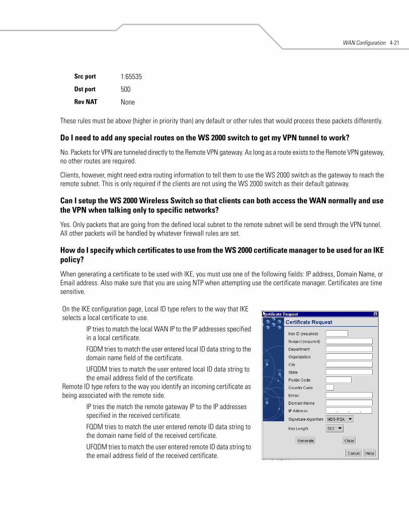
WAN Configuration 4-21
These rules must be above (higher in priority than) any default or other rules that would process these packets differently.
Do I need to add any special routes on the WS 2000 switch to get my VPN tunnel to work?
No. Packets for VPN are tunneled directly to the Remote VPN gateway. As long as a route exists to the Remote VPN gateway, no other routes are required.
Clients, however, might need extra routing information to tell them to use the WS 2000 switch as the gateway to reach the remote subnet. This is only required if the clients are not using the WS 2000 switch as their default gateway.
Can I setup the WS 2000 Wireless Switch so that clients can both access the WAN normally and use the VPN when talking only to specific networks?
Yes. Only packets that are going from the defined local subnet to the remote subnet will be send through the VPN tunnel. All other packets will be handled by whatever firewall rules are set.
How do I specify which certificates to use from the WS 2000 certificate manager to be used for an IKE policy?
When generating a certificate to be used with IKE, you must use one of the following fields: IP address, Domain Name, or Email address. Also make sure that you are using NTP when attempting use the certificate manager. Certificates are time sensitive.
Src port 1:65535
Dst port 500
Rev NAT None
On the IKE configuration page, Local ID type refers to the way that IKE selects a local certificate to use.
IP tries to match the local WAN IP to the IP addresses specified in a local certificate.
FQDM tries to match the user entered local ID data string to the domain name field of the certificate.
UFQDM tries to match the user entered local ID data string to the email address field of the certificate.
Remote ID type refers to the way you identify an incoming certificate as being associated with the remote side.
IP tries the match the remote gateway IP to the IP addresses specified in the received certificate.
FQDM tries to match the user entered remote ID data string to the domain name field of the received certificate.
UFQDM tries to match the user entered remote ID data string to the email address field of the received certificate.
WS 2000 Wireless Switch System Reference Guide4-22
I am using a direct cable connection between by two VPN gateways for testing and cannot get a tunnel established, yet it works when I setup them up across another network or router. What gives?
The packet processing architecture of the WS 2000 VPN solution requires a WAN default gateway to work properly. When connecting two gateways directly, you really do not need a default gateway when the two addresses are on the same subnet. As a workaround, you can point the WS 2000 switch’s WAN default gateway to be the other VPN gateway, and vice-versa.
My WS 2000 switch is a DHCP client on my WAN interface. How can I setup a tunnel without knowing my WAN IP address?
First of all, one end of a VPN tunnel must have a static IP address. Assuming the other end of your VPN tunnel has a static IP, here is how you configure your WS 2000 switch to use a DHCP WAN address with VPN.
1. Your VPN tunnel entry must have the Local WAN IP set to 0.0.0.0.
2. If you are using the IKE, the Local ID type (and corresponding Remote ID type on the other end) cannot be set to IP, since the IP address is not known.
How can I setup the WS 2000 switch to accept VPN tunnels from gateways that have a DHCP WAN address?
To accept a VPN tunnel from a unknown (DHCP) address, the WS 2000 Wireless Switch operates in what is called responder-only mode. That is, it cannot initiate the VPN connection. It can only wait for a VPN connection to come in. Clients behind a responder-only cannot connect to the remote subnet until the remote subnet has connected to them.
To setup responder-only mode, set the Remote Gateway to 0.0.0.0. If you are using IKE the following restrictions are in place:
• Remote ID type cannot be IP. We do not know the IP of the remote since it is DHCP.
• IKE Authentication Mode cannot be set to PSK if IKE mode is set to Main Mode.
• You may not use xAuth for this tunnel.
I have two WS 2000 switches and both have DHCP WAN addresses. Is there any possible way to open a VPN tunnel between them?
Yes, but the configuration for each tunnel will need to change anytime a WAN IP lease expires. You can make this work temporarily by performing the following steps:
1. Set 0.0.0.0 as the local WAN IP for each gateway.
2. Configure the opposite WS 2000 switch’s current DHCP address as the Remote Gateway. This is the field that needs to change every time the DHCP addresses change.
3. If using IKE, you cannot use ID type IP for either Local or Remote ID types.
I have set up my tunnel and the status still says “Not Connected.” What should I do now?
VPN tunnels are negotiated on an as-needed basis. If you have not sent any traffic between the two subnets, the tunnel will not be established. Once a packed is sent between the two subnets, the VPN tunnel setup will occur.
I still can’t get my tunnel to work after attempting to initiate traffic between the 2 subnets. What now?
Here are some troubleshooting tips:
1. Verify that you can ping each of the remote gateway IP addresses from clients on either side. Failed pings can indicates general network connection problems.

WAN Configuration 4-23
2. Pinging the internal gateway address of the remote subnet should run the ping through the tunnel as well. Allowing you to test even if there are no clients on the remote end.
3. Verify that your WAN IP address is not DHCP. VPN requires a static WAN IP address to work.

WS 2000 Wireless Switch System Reference Guide4-24
5Wireless Configuration
Enabling Wireless LANs (WLANs) . . . . . . . . . . . . . . . . . . . . . . . . . . . . . . . . . . . . . . . . . . . . . . . . . . . . . . . . . . . . 5-3Wireless Summary Area . . . . . . . . . . . . . . . . . . . . . . . . . . . . . . . . . . . . . . . . . . . . . . . . . . . . . . . . . . . . . . . 5-3Access Port Adoption . . . . . . . . . . . . . . . . . . . . . . . . . . . . . . . . . . . . . . . . . . . . . . . . . . . . . . . . . . . . . . . . . . 5-4
Configuring Wireless LANs . . . . . . . . . . . . . . . . . . . . . . . . . . . . . . . . . . . . . . . . . . . . . . . . . . . . . . . . . . . . . . . . . 5-5Configure Wireless LAN Security . . . . . . . . . . . . . . . . . . . . . . . . . . . . . . . . . . . . . . . . . . . . . . . . . . . . . . . . . . . . 5-6
Selecting the Authentication Method . . . . . . . . . . . . . . . . . . . . . . . . . . . . . . . . . . . . . . . . . . . . . . . . . . . . . 5-6Configuring 802.1x EAP Authentication. . . . . . . . . . . . . . . . . . . . . . . . . . . . . . . . . . . . . . . . . . . . . . . . . . . . 5-7Configuring Kerberos Authentication . . . . . . . . . . . . . . . . . . . . . . . . . . . . . . . . . . . . . . . . . . . . . . . . . . . . . 5-8Setting the Encryption Method . . . . . . . . . . . . . . . . . . . . . . . . . . . . . . . . . . . . . . . . . . . . . . . . . . . . . . . . . . 5-9Configuring WEP Encryption . . . . . . . . . . . . . . . . . . . . . . . . . . . . . . . . . . . . . . . . . . . . . . . . . . . . . . . . . . . . 5-9Configuring WPA-TKIP Encryption . . . . . . . . . . . . . . . . . . . . . . . . . . . . . . . . . . . . . . . . . . . . . . . . . . . . . . . 5-10Configuring WPA2-CCMP (802.11i) Encryption . . . . . . . . . . . . . . . . . . . . . . . . . . . . . . . . . . . . . . . . . . . . . 5-11KeyGuard . . . . . . . . . . . . . . . . . . . . . . . . . . . . . . . . . . . . . . . . . . . . . . . . . . . . . . . . . . . . . . . . . . . . . . . . . . 5-12No Encryption . . . . . . . . . . . . . . . . . . . . . . . . . . . . . . . . . . . . . . . . . . . . . . . . . . . . . . . . . . . . . . . . . . . . . . 5-12Mobile Unit Access Control List (ACL) . . . . . . . . . . . . . . . . . . . . . . . . . . . . . . . . . . . . . . . . . . . . . . . . . . . 5-13
Configuring Access Ports . . . . . . . . . . . . . . . . . . . . . . . . . . . . . . . . . . . . . . . . . . . . . . . . . . . . . . . . . . . . . . . . . . 5-13Setting Default Access Port Settings. . . . . . . . . . . . . . . . . . . . . . . . . . . . . . . . . . . . . . . . . . . . . . . . . . . . . . . . . 5-16
Common Settings to All Radio Types . . . . . . . . . . . . . . . . . . . . . . . . . . . . . . . . . . . . . . . . . . . . . . . . . . . . 5-16Radio-Specific Settings . . . . . . . . . . . . . . . . . . . . . . . . . . . . . . . . . . . . . . . . . . . . . . . . . . . . . . . . . . . . . . . 5-19
Advanced Access Port Settings . . . . . . . . . . . . . . . . . . . . . . . . . . . . . . . . . . . . . . . . . . . . . . . . . . . . . . . . . . . . . 5-19Radio Settings . . . . . . . . . . . . . . . . . . . . . . . . . . . . . . . . . . . . . . . . . . . . . . . . . . . . . . . . . . . . . . . . . . . . . . 5-20Antenna Settings . . . . . . . . . . . . . . . . . . . . . . . . . . . . . . . . . . . . . . . . . . . . . . . . . . . . . . . . . . . . . . . . . . . . 5-21Advanced Properties . . . . . . . . . . . . . . . . . . . . . . . . . . . . . . . . . . . . . . . . . . . . . . . . . . . . . . . . . . . . . . . . . 5-21
Quality of Service Configuration . . . . . . . . . . . . . . . . . . . . . . . . . . . . . . . . . . . . . . . . . . . . . . . . . . . . . . . . . . . . 5-22Setting the Bandwidth Share and Mode . . . . . . . . . . . . . . . . . . . . . . . . . . . . . . . . . . . . . . . . . . . . . . . . . . 5-23Configuring Voice Prioritization and Multicast Address Settings . . . . . . . . . . . . . . . . . . . . . . . . . . . . . . . 5-24

WS 2000 Wireless Switch System Reference Guide5-2
Setting Up Port Authentication for AP 300 Access Ports. . . . . . . . . . . . . . . . . . . . . . . . . . . . . . . . . . . . . . . . . .5-24Rogue Access Port Detection . . . . . . . . . . . . . . . . . . . . . . . . . . . . . . . . . . . . . . . . . . . . . . . . . . . . . . . . . . . . . . .5-25
Setting Up the Detection Method . . . . . . . . . . . . . . . . . . . . . . . . . . . . . . . . . . . . . . . . . . . . . . . . . . . . . . .5-26Defining and Maintain Approved APs' Rules . . . . . . . . . . . . . . . . . . . . . . . . . . . . . . . . . . . . . . . . . . . . . . .5-27Examine the Approve and Rogue Access Ports . . . . . . . . . . . . . . . . . . . . . . . . . . . . . . . . . . . . . . . . . . . . .5-27Setting SNMP Traps for Rogue APs. . . . . . . . . . . . . . . . . . . . . . . . . . . . . . . . . . . . . . . . . . . . . . . . . . . . . .5-30
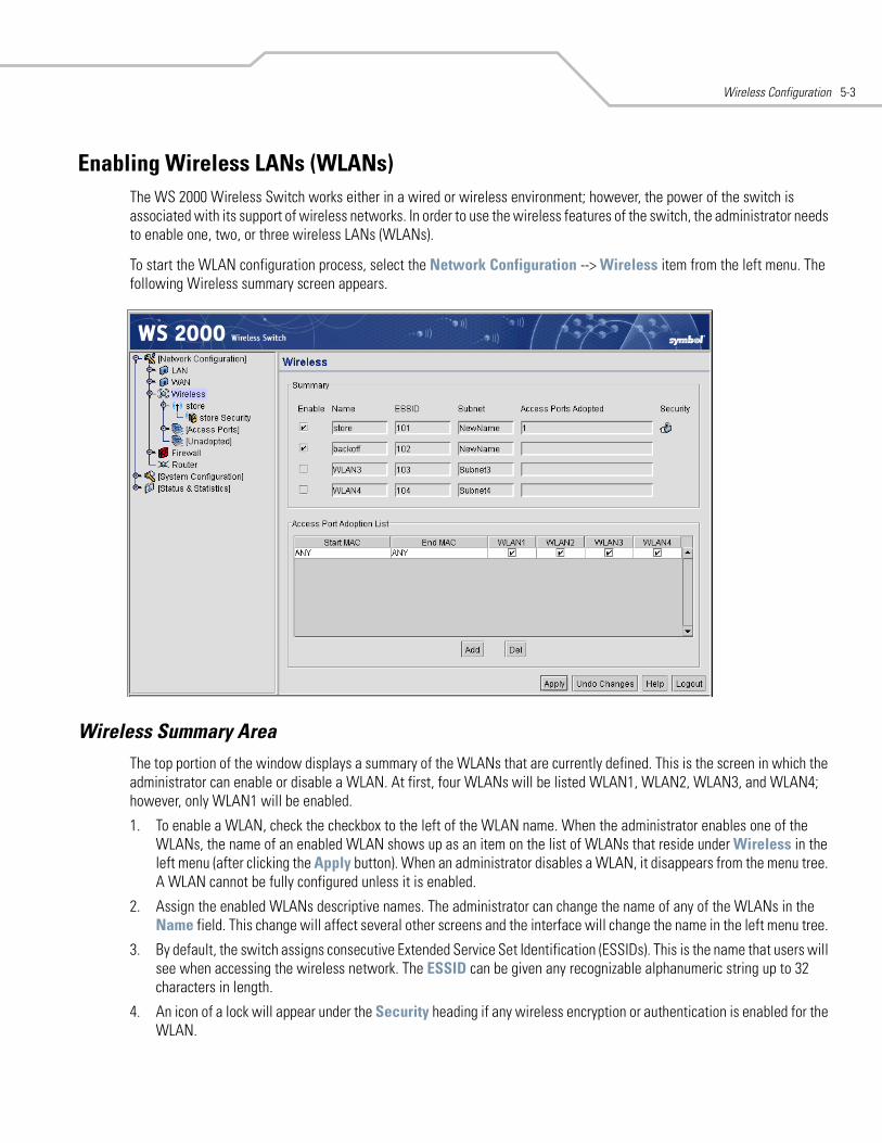
Wireless Configuration 5-3
Enabling Wireless LANs (WLANs)The WS 2000 Wireless Switch works either in a wired or wireless environment; however, the power of the switch is associated with its support of wireless networks. In order to use the wireless features of the switch, the administrator needs to enable one, two, or three wireless LANs (WLANs).
To start the WLAN configuration process, select the Network Configuration --> Wireless item from the left menu. The following Wireless summary screen appears.
Wireless Summary AreaThe top portion of the window displays a summary of the WLANs that are currently defined. This is the screen in which the administrator can enable or disable a WLAN. At first, four WLANs will be listed WLAN1, WLAN2, WLAN3, and WLAN4; however, only WLAN1 will be enabled.
1. To enable a WLAN, check the checkbox to the left of the WLAN name. When the administrator enables one of the WLANs, the name of an enabled WLAN shows up as an item on the list of WLANs that reside under Wireless in the left menu (after clicking the Apply button). When an administrator disables a WLAN, it disappears from the menu tree. A WLAN cannot be fully configured unless it is enabled.
2. Assign the enabled WLANs descriptive names. The administrator can change the name of any of the WLANs in the Name field. This change will affect several other screens and the interface will change the name in the left menu tree.
3. By default, the switch assigns consecutive Extended Service Set Identification (ESSIDs). This is the name that users will see when accessing the wireless network. The ESSID can be given any recognizable alphanumeric string up to 32 characters in length.
4. An icon of a lock will appear under the Security heading if any wireless encryption or authentication is enabled for the WLAN.
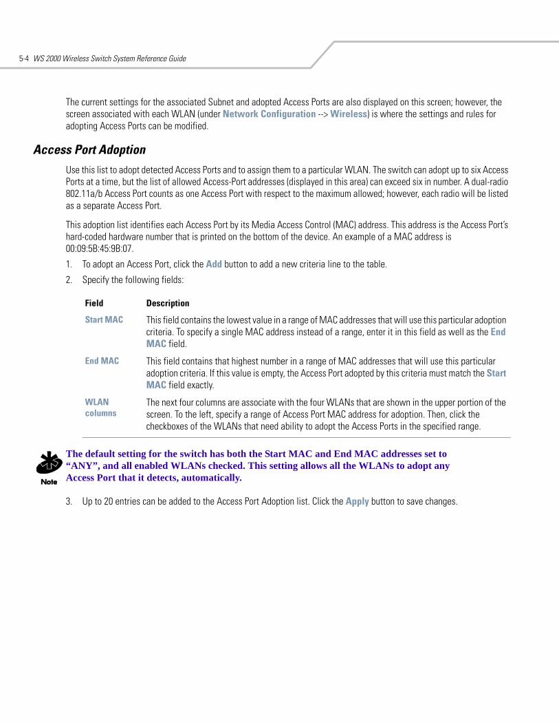
WS 2000 Wireless Switch System Reference Guide5-4
The current settings for the associated Subnet and adopted Access Ports are also displayed on this screen; however, the screen associated with each WLAN (under Network Configuration --> Wireless) is where the settings and rules for adopting Access Ports can be modified.
Access Port AdoptionUse this list to adopt detected Access Ports and to assign them to a particular WLAN. The switch can adopt up to six Access Ports at a time, but the list of allowed Access-Port addresses (displayed in this area) can exceed six in number. A dual-radio 802.11a/b Access Port counts as one Access Port with respect to the maximum allowed; however, each radio will be listed as a separate Access Port.
This adoption list identifies each Access Port by its Media Access Control (MAC) address. This address is the Access Port’s hard-coded hardware number that is printed on the bottom of the device. An example of a MAC address is 00:09:5B:45:9B:07.
1. To adopt an Access Port, click the Add button to add a new criteria line to the table.
2. Specify the following fields:
The default setting for the switch has both the Start MAC and End MAC addresses set to “ANY”, and all enabled WLANs checked. This setting allows all the WLANs to adopt any Access Port that it detects, automatically.
3. Up to 20 entries can be added to the Access Port Adoption list. Click the Apply button to save changes.
Field Description
Start MAC This field contains the lowest value in a range of MAC addresses that will use this particular adoption criteria. To specify a single MAC address instead of a range, enter it in this field as well as the End MAC field.
End MAC This field contains that highest number in a range of MAC addresses that will use this particular adoption criteria. If this value is empty, the Access Port adopted by this criteria must match the Start MAC field exactly.
WLAN columns
The next four columns are associate with the four WLANs that are shown in the upper portion of the screen. To the left, specify a range of Access Port MAC address for adoption. Then, click the checkboxes of the WLANs that need ability to adopt the Access Ports in the specified range.
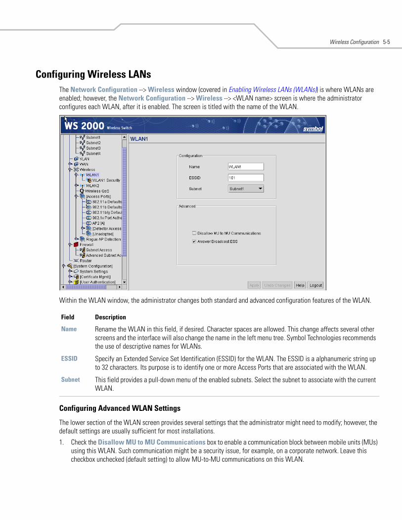
Wireless Configuration 5-5
Configuring Wireless LANsThe Network Configuration --> Wireless window (covered in Enabling Wireless LANs (WLANs)) is where WLANs are enabled; however, the Network Configuration --> Wireless --> <WLAN name> screen is where the administrator configures each WLAN, after it is enabled. The screen is titled with the name of the WLAN.
Within the WLAN window, the administrator changes both standard and advanced configuration features of the WLAN.
Configuring Advanced WLAN Settings
The lower section of the WLAN screen provides several settings that the administrator might need to modify; however, the default settings are usually sufficient for most installations.
1. Check the Disallow MU to MU Communications box to enable a communication block between mobile units (MUs) using this WLAN. Such communication might be a security issue, for example, on a corporate network. Leave this checkbox unchecked (default setting) to allow MU-to-MU communications on this WLAN.
Field Description
Name Rename the WLAN in this field, if desired. Character spaces are allowed. This change affects several other screens and the interface will also change the name in the left menu tree. Symbol Technologies recommends the use of descriptive names for WLANs.
ESSID Specify an Extended Service Set Identification (ESSID) for the WLAN. The ESSID is a alphanumeric string up to 32 characters. Its purpose is to identify one or more Access Ports that are associated with the WLAN.
Subnet This field provides a pull-down menu of the enabled subnets. Select the subnet to associate with the current WLAN.
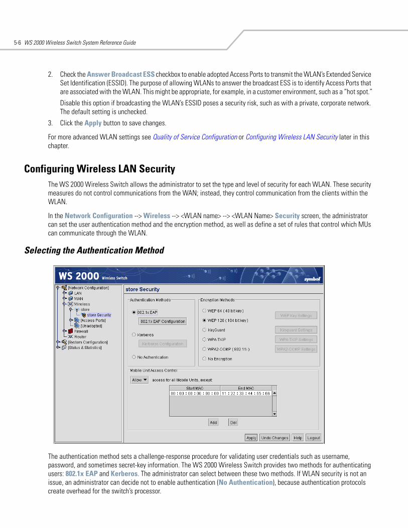
WS 2000 Wireless Switch System Reference Guide5-6
2. Check the Answer Broadcast ESS checkbox to enable adopted Access Ports to transmit the WLAN’s Extended Service Set Identification (ESSID). The purpose of allowing WLANs to answer the broadcast ESS is to identify Access Ports that are associated with the WLAN. This might be appropriate, for example, in a customer environment, such as a “hot spot.”
Disable this option if broadcasting the WLAN’s ESSID poses a security risk, such as with a private, corporate network. The default setting is unchecked.
3. Click the Apply button to save changes.
For more advanced WLAN settings see Quality of Service Configuration or Configuring Wireless LAN Security later in this chapter.
Configuring Wireless LAN SecurityThe WS 2000 Wireless Switch allows the administrator to set the type and level of security for each WLAN. These security measures do not control communications from the WAN; instead, they control communication from the clients within the WLAN.
In the Network Configuration --> Wireless --> <WLAN name> --> <WLAN Name> Security screen, the administrator can set the user authentication method and the encryption method, as well as define a set of rules that control which MUs can communicate through the WLAN.
Selecting the Authentication Method
The authentication method sets a challenge-response procedure for validating user credentials such as username, password, and sometimes secret-key information. The WS 2000 Wireless Switch provides two methods for authenticating users: 802.1x EAP and Kerberos. The administrator can select between these two methods. If WLAN security is not an issue, an administrator can decide not to enable authentication (No Authentication), because authentication protocols create overhead for the switch’s processor.
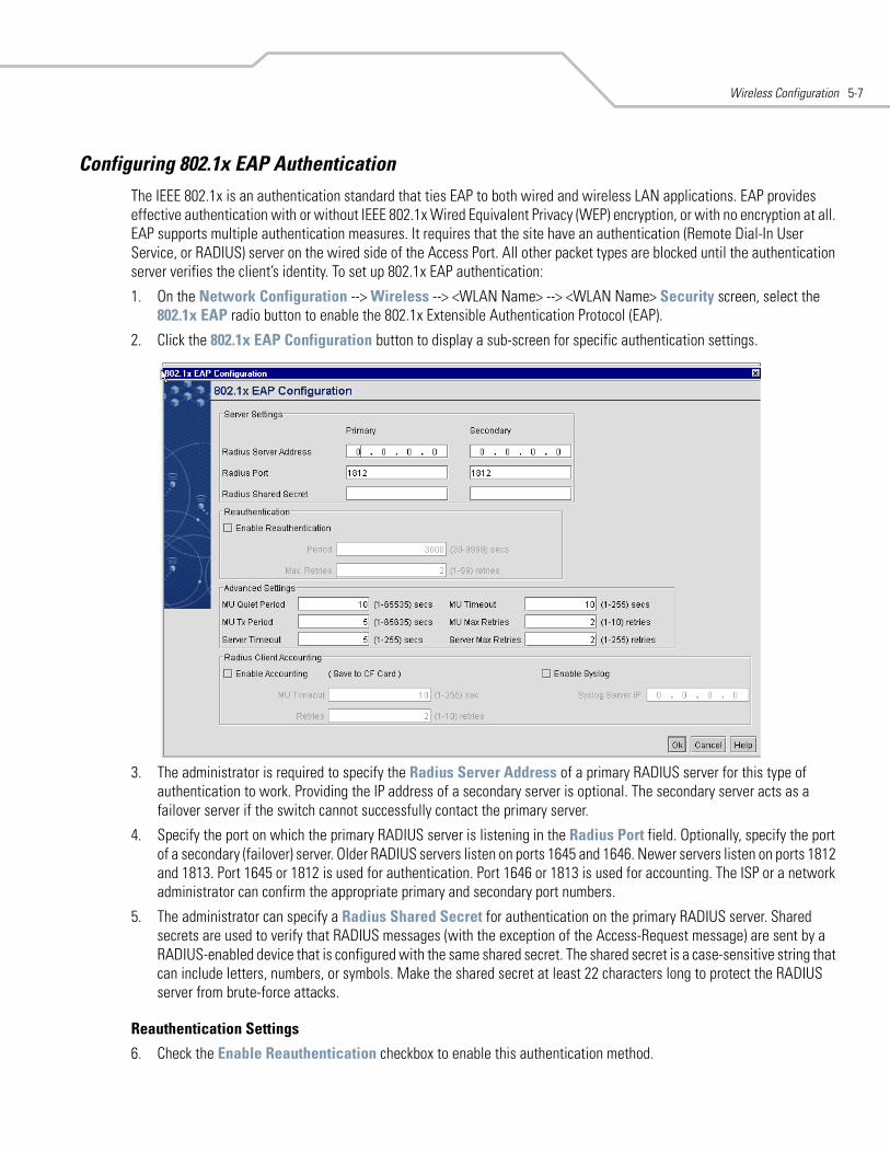
Wireless Configuration 5-7
Configuring 802.1x EAP AuthenticationThe IEEE 802.1x is an authentication standard that ties EAP to both wired and wireless LAN applications. EAP provides effective authentication with or without IEEE 802.1x Wired Equivalent Privacy (WEP) encryption, or with no encryption at all. EAP supports multiple authentication measures. It requires that the site have an authentication (Remote Dial-In User Service, or RADIUS) server on the wired side of the Access Port. All other packet types are blocked until the authentication server verifies the client’s identity. To set up 802.1x EAP authentication:
1. On the Network Configuration --> Wireless --> <WLAN Name> --> <WLAN Name> Security screen, select the 802.1x EAP radio button to enable the 802.1x Extensible Authentication Protocol (EAP).
2. Click the 802.1x EAP Configuration button to display a sub-screen for specific authentication settings.
3. The administrator is required to specify the Radius Server Address of a primary RADIUS server for this type of authentication to work. Providing the IP address of a secondary server is optional. The secondary server acts as a failover server if the switch cannot successfully contact the primary server.
4. Specify the port on which the primary RADIUS server is listening in the Radius Port field. Optionally, specify the port of a secondary (failover) server. Older RADIUS servers listen on ports 1645 and 1646. Newer servers listen on ports 1812 and 1813. Port 1645 or 1812 is used for authentication. Port 1646 or 1813 is used for accounting. The ISP or a network administrator can confirm the appropriate primary and secondary port numbers.
5. The administrator can specify a Radius Shared Secret for authentication on the primary RADIUS server. Shared secrets are used to verify that RADIUS messages (with the exception of the Access-Request message) are sent by a RADIUS-enabled device that is configured with the same shared secret. The shared secret is a case-sensitive string that can include letters, numbers, or symbols. Make the shared secret at least 22 characters long to protect the RADIUS server from brute-force attacks.
Reauthentication Settings
6. Check the Enable Reauthentication checkbox to enable this authentication method.
WS 2000 Wireless Switch System Reference Guide5-8
7. In the Period field, set the EAP reauthentication period to match the appropriate level of security. A shorter time interval (~30 seconds or longer) provides tighter security on this WLAN’s wireless connections. A longer interval (5000-9999 seconds) relaxes security on wireless connections. The reauthentication period setting does not affect a wireless connection’s throughput. The engaged Access Port continues to forward traffic during the reauthentication process.
8. In the Max. Retries field, set the maximum number of retries for a client to successfully reauthenticate after failing to complete the EAP process. If the mobile unit fails the authentication process in specified number of retries, the switch will terminate the connection to the mobile unit.
Advanced Settings
9. The MU Quiet Period field allows the administrator to specify the idle time (in seconds) between a mobile unit’s authentication attempts, as required by the server.
10. The MU Timeout field allows the administrator to specify the time (in seconds) for the mobile unit’s retransmission of EAP-Request packets.
11. The MU Tx Period field allows the administrator to specify the time period (in seconds) for the server’s retransmission of the EAP-Request/Identity frame.
12. The MU Max Retries field allows the administrator to set the maximum number of times for the mobile unit to retransmit an EAP-Request frame to the server before it times out the authentication session. Note that this is a different value from the Max Retry field at the top of the window.
13. The Server Timeout field indicates the maximum time (in seconds) that the switch will wait for the server’s transmission of EAP Transmit packets.
14. The Server Max Retries field allows the administrator to set the maximum number of times for the server to retransmit an EAP-Request frame to the client before it times out the authentication session. Note that this is a different value from the Max. Retries field at the top of the window.
When changing the Server Max Retries setting to anything other than the default value, there is a known bug that can cause RADIUS authentication to fail.
RADIUS Client Accounting and Syslog Setup
15. RADIUS accounting allows for the delivery of accounting packets from a Network Access Server (NAS) to the RADIUS accounting server where the information is stored. To enable this feature, click the Enable Accounting box.
16. If accounting is enabled, enter the maximum amount of time a client will wait for an acknowledgement from the RADIUS accounting server before resending the accounting packet in the MU Timeout field. In the Retries field, enter the maximum number of times for the client will resend the accounting packet to the RADIUS accounting server before giving up.
17. To enable 802.1x EAP message logging to an external Syslog server, check the Enable Syslog box and then specify the IP address of the syslog server in the Syslog Server IP field.
18. Click the Ok button to save changes.
Configuring Kerberos AuthenticationKerberos provides a strong authentication method for client/server applications by using secret-key cryptography. Using this protocol, a client can prove their identity to a server (and vice versa) across an insecure network connection. After a client and server use Kerberos to prove their identity, they can encrypt all communications to assure privacy and data integrity.
1. Select the Kerberos radio button to enable Kerberos authentication.
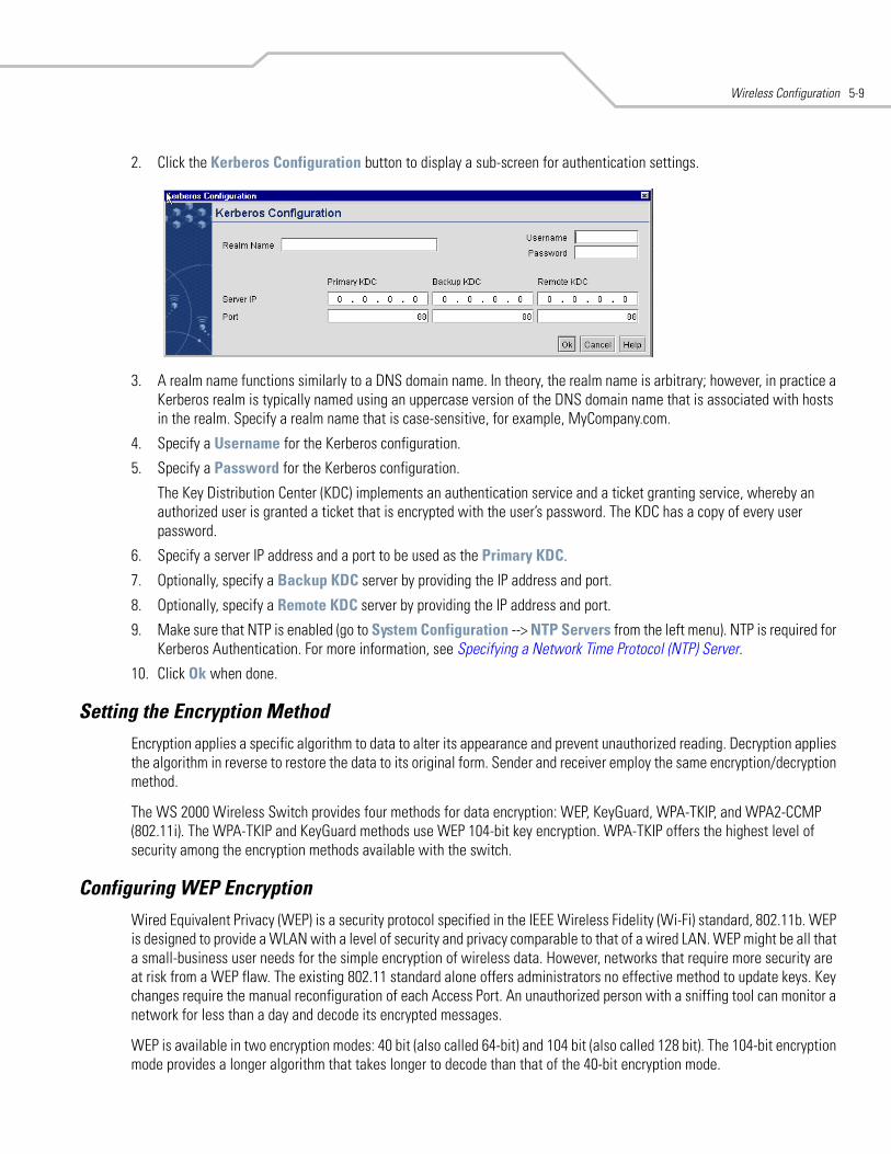
Wireless Configuration 5-9
2. Click the Kerberos Configuration button to display a sub-screen for authentication settings.
3. A realm name functions similarly to a DNS domain name. In theory, the realm name is arbitrary; however, in practice a Kerberos realm is typically named using an uppercase version of the DNS domain name that is associated with hosts in the realm. Specify a realm name that is case-sensitive, for example, MyCompany.com.
4. Specify a Username for the Kerberos configuration.
5. Specify a Password for the Kerberos configuration.
The Key Distribution Center (KDC) implements an authentication service and a ticket granting service, whereby an authorized user is granted a ticket that is encrypted with the user’s password. The KDC has a copy of every user password.
6. Specify a server IP address and a port to be used as the Primary KDC.
7. Optionally, specify a Backup KDC server by providing the IP address and port.
8. Optionally, specify a Remote KDC server by providing the IP address and port.
9. Make sure that NTP is enabled (go to System Configuration --> NTP Servers from the left menu). NTP is required for Kerberos Authentication. For more information, see Specifying a Network Time Protocol (NTP) Server.
10. Click Ok when done.
Setting the Encryption Method Encryption applies a specific algorithm to data to alter its appearance and prevent unauthorized reading. Decryption applies the algorithm in reverse to restore the data to its original form. Sender and receiver employ the same encryption/decryption method.
The WS 2000 Wireless Switch provides four methods for data encryption: WEP, KeyGuard, WPA-TKIP, and WPA2-CCMP (802.11i). The WPA-TKIP and KeyGuard methods use WEP 104-bit key encryption. WPA-TKIP offers the highest level of security among the encryption methods available with the switch.
Configuring WEP Encryption Wired Equivalent Privacy (WEP) is a security protocol specified in the IEEE Wireless Fidelity (Wi-Fi) standard, 802.11b. WEP is designed to provide a WLAN with a level of security and privacy comparable to that of a wired LAN. WEP might be all that a small-business user needs for the simple encryption of wireless data. However, networks that require more security are at risk from a WEP flaw. The existing 802.11 standard alone offers administrators no effective method to update keys. Key changes require the manual reconfiguration of each Access Port. An unauthorized person with a sniffing tool can monitor a network for less than a day and decode its encrypted messages.
WEP is available in two encryption modes: 40 bit (also called 64-bit) and 104 bit (also called 128 bit). The 104-bit encryption mode provides a longer algorithm that takes longer to decode than that of the 40-bit encryption mode.
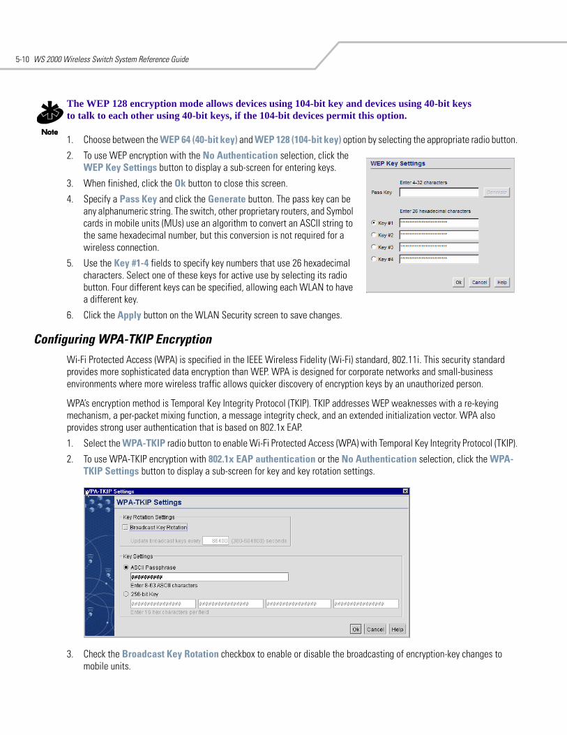
WS 2000 Wireless Switch System Reference Guide5-10
The WEP 128 encryption mode allows devices using 104-bit key and devices using 40-bit keys to talk to each other using 40-bit keys, if the 104-bit devices permit this option.
1. Choose between the WEP 64 (40-bit key) and WEP 128 (104-bit key) option by selecting the appropriate radio button.
2. To use WEP encryption with the No Authentication selection, click the WEP Key Settings button to display a sub-screen for entering keys.
3. When finished, click the Ok button to close this screen.
4. Specify a Pass Key and click the Generate button. The pass key can be any alphanumeric string. The switch, other proprietary routers, and Symbol cards in mobile units (MUs) use an algorithm to convert an ASCII string to the same hexadecimal number, but this conversion is not required for a wireless connection.
5. Use the Key #1-4 fields to specify key numbers that use 26 hexadecimal characters. Select one of these keys for active use by selecting its radio button. Four different keys can be specified, allowing each WLAN to have a different key.
6. Click the Apply button on the WLAN Security screen to save changes.
Configuring WPA-TKIP EncryptionWi-Fi Protected Access (WPA) is specified in the IEEE Wireless Fidelity (Wi-Fi) standard, 802.11i. This security standard provides more sophisticated data encryption than WEP. WPA is designed for corporate networks and small-business environments where more wireless traffic allows quicker discovery of encryption keys by an unauthorized person.
WPA’s encryption method is Temporal Key Integrity Protocol (TKIP). TKIP addresses WEP weaknesses with a re-keying mechanism, a per-packet mixing function, a message integrity check, and an extended initialization vector. WPA also provides strong user authentication that is based on 802.1x EAP.
1. Select the WPA-TKIP radio button to enable Wi-Fi Protected Access (WPA) with Temporal Key Integrity Protocol (TKIP).
2. To use WPA-TKIP encryption with 802.1x EAP authentication or the No Authentication selection, click the WPA-TKIP Settings button to display a sub-screen for key and key rotation settings.
3. Check the Broadcast Key Rotation checkbox to enable or disable the broadcasting of encryption-key changes to mobile units.
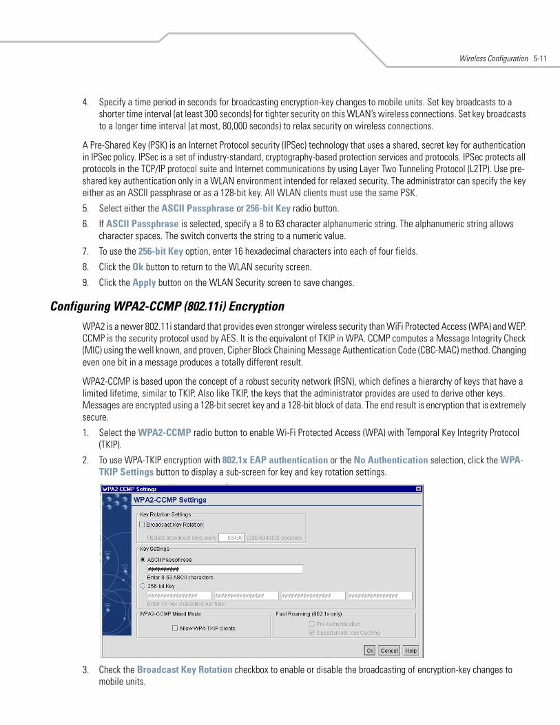
Wireless Configuration 5-11
4. Specify a time period in seconds for broadcasting encryption-key changes to mobile units. Set key broadcasts to a shorter time interval (at least 300 seconds) for tighter security on this WLAN’s wireless connections. Set key broadcasts to a longer time interval (at most, 80,000 seconds) to relax security on wireless connections.
A Pre-Shared Key (PSK) is an Internet Protocol security (IPSec) technology that uses a shared, secret key for authentication in IPSec policy. IPSec is a set of industry-standard, cryptography-based protection services and protocols. IPSec protects all protocols in the TCP/IP protocol suite and Internet communications by using Layer Two Tunneling Protocol (L2TP). Use pre-shared key authentication only in a WLAN environment intended for relaxed security. The administrator can specify the key either as an ASCII passphrase or as a 128-bit key. All WLAN clients must use the same PSK.
5. Select either the ASCII Passphrase or 256-bit Key radio button.
6. If ASCII Passphrase is selected, specify a 8 to 63 character alphanumeric string. The alphanumeric string allows character spaces. The switch converts the string to a numeric value.
7. To use the 256-bit Key option, enter 16 hexadecimal characters into each of four fields.
8. Click the Ok button to return to the WLAN security screen.
9. Click the Apply button on the WLAN Security screen to save changes.
Configuring WPA2-CCMP (802.11i) EncryptionWPA2 is a newer 802.11i standard that provides even stronger wireless security than WiFi Protected Access (WPA) and WEP. CCMP is the security protocol used by AES. It is the equivalent of TKIP in WPA. CCMP computes a Message Integrity Check (MIC) using the well known, and proven, Cipher Block Chaining Message Authentication Code (CBC-MAC) method. Changing even one bit in a message produces a totally different result.
WPA2-CCMP is based upon the concept of a robust security network (RSN), which defines a hierarchy of keys that have a limited lifetime, similar to TKIP. Also like TKIP, the keys that the administrator provides are used to derive other keys. Messages are encrypted using a 128-bit secret key and a 128-bit block of data. The end result is encryption that is extremely secure.
1. Select the WPA2-CCMP radio button to enable Wi-Fi Protected Access (WPA) with Temporal Key Integrity Protocol (TKIP).
2. To use WPA-TKIP encryption with 802.1x EAP authentication or the No Authentication selection, click the WPA-TKIP Settings button to display a sub-screen for key and key rotation settings.
3. Check the Broadcast Key Rotation checkbox to enable or disable the broadcasting of encryption-key changes to mobile units.
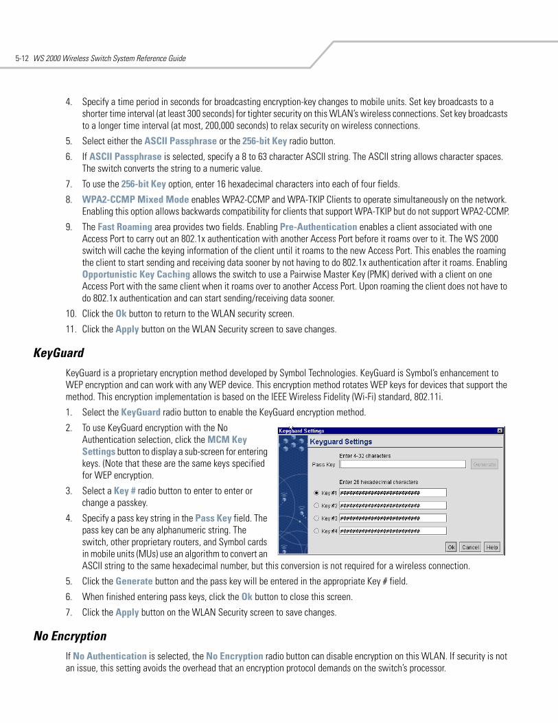
WS 2000 Wireless Switch System Reference Guide5-12
4. Specify a time period in seconds for broadcasting encryption-key changes to mobile units. Set key broadcasts to a shorter time interval (at least 300 seconds) for tighter security on this WLAN’s wireless connections. Set key broadcasts to a longer time interval (at most, 200,000 seconds) to relax security on wireless connections.
5. Select either the ASCII Passphrase or the 256-bit Key radio button.
6. If ASCII Passphrase is selected, specify a 8 to 63 character ASCII string. The ASCII string allows character spaces. The switch converts the string to a numeric value.
7. To use the 256-bit Key option, enter 16 hexadecimal characters into each of four fields.
8. WPA2-CCMP Mixed Mode enables WPA2-CCMP and WPA-TKIP Clients to operate simultaneously on the network. Enabling this option allows backwards compatibility for clients that support WPA-TKIP but do not support WPA2-CCMP.
9. The Fast Roaming area provides two fields. Enabling Pre-Authentication enables a client associated with one Access Port to carry out an 802.1x authentication with another Access Port before it roams over to it. The WS 2000 switch will cache the keying information of the client until it roams to the new Access Port. This enables the roaming the client to start sending and receiving data sooner by not having to do 802.1x authentication after it roams. Enabling Opportunistic Key Caching allows the switch to use a Pairwise Master Key (PMK) derived with a client on one Access Port with the same client when it roams over to another Access Port. Upon roaming the client does not have to do 802.1x authentication and can start sending/receiving data sooner.
10. Click the Ok button to return to the WLAN security screen.
11. Click the Apply button on the WLAN Security screen to save changes.
KeyGuardKeyGuard is a proprietary encryption method developed by Symbol Technologies. KeyGuard is Symbol’s enhancement to WEP encryption and can work with any WEP device. This encryption method rotates WEP keys for devices that support the method. This encryption implementation is based on the IEEE Wireless Fidelity (Wi-Fi) standard, 802.11i.
1. Select the KeyGuard radio button to enable the KeyGuard encryption method.
2. To use KeyGuard encryption with the No Authentication selection, click the MCM Key Settings button to display a sub-screen for entering keys. (Note that these are the same keys specified for WEP encryption.
3. Select a Key # radio button to enter to enter or change a passkey.
4. Specify a pass key string in the Pass Key field. The pass key can be any alphanumeric string. The switch, other proprietary routers, and Symbol cards in mobile units (MUs) use an algorithm to convert an ASCII string to the same hexadecimal number, but this conversion is not required for a wireless connection.
5. Click the Generate button and the pass key will be entered in the appropriate Key # field.
6. When finished entering pass keys, click the Ok button to close this screen.
7. Click the Apply button on the WLAN Security screen to save changes.
No Encryption If No Authentication is selected, the No Encryption radio button can disable encryption on this WLAN. If security is not an issue, this setting avoids the overhead that an encryption protocol demands on the switch’s processor.
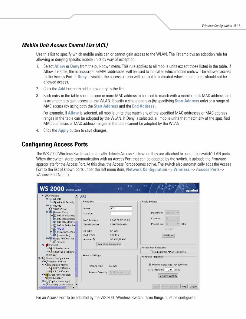
Wireless Configuration 5-13
Mobile Unit Access Control List (ACL) Use this list to specify which mobile units can or cannot gain access to the WLAN. The list employs an adoption rule for allowing or denying specific mobile units by way of exception.
1. Select Allow or Deny from the pull-down menu. This rule applies to all mobile units except those listed in the table. If Allow is visible, the access criteria (MAC addresses) will be used to indicated which mobile units will be allowed access to the Access Port. If Deny is visible, the access criteria will be used to indicated which mobile units should not be allowed access.
2. Click the Add button to add a new entry to the list.
3. Each entry in the table specifies one or more MAC address to be used to match with a mobile unit’s MAC address that is attempting to gain access to the WLAN. Specify a single address (by specifying Start Address only) or a range of MAC access (by using both the Start Address and the End Address).
For example, if Allow is selected, all mobile units that match any of the specified MAC addresses or MAC address ranges in the table can be adopted by the WLAN. If Deny is selected, all mobile units that match any of the specified MAC addresses or MAC address ranges in the table cannot be adopted by the WLAN.
4. Click the Apply button to save changes.
Configuring Access PortsThe WS 2000 Wireless Switch automatically detects Access Ports when they are attached to one of the switch’s LAN ports. When the switch starts communication with an Access Port that can be adopted by the switch, it uploads the firmware appropriate for the Access Port. At this time, the Access Port becomes active. The switch also automatically adds the Access Port to the list of known ports under the left menu item, Network Configuration --> Wireless --> Access Ports--> <Access Port Name>.
For an Access Port to be adopted by the WS 2000 Wireless Switch, three things must be configured:
WS 2000 Wireless Switch System Reference Guide5-14
1. The Country field in the System Settings screen must be set.
2. The Access Port’s MAC Address must be set as one of the addresses that can be adopted by one of the enabled WLANs.
3. A WLAN that can adopt Access Port must be associated with an enabled subnet. (See Configuring Wireless LANs.)
The switch can adopt up to six Access Ports at a time, but the number of Access Ports listed can exceed six in number. A dual-radio 802.11a/b Access Port counts as one Access Port with respect to the maximum allowed; however, each radio will be listed as a separate Access Port in the list of Access Ports.
The switch creates a default name for a newly found switch consisting of “AP” and a unique number. During this detection process, the switch collects the following information from the Access Port:
The switch also sets several default values for the channel and the power level based upon the Location information set in the System Settings screen and upon settings in the Access Port Default Settings screen for the radio type.
The WS 2000 Wireless Switch GUI also allows the administrator to refine the basic Access Port configuration that is set at the point of detection. To examine or change that information:
1. Select Network Configuration --> Wireless --> Access Ports from the left menu and then click the + to the left of the menu item. The detected Access Ports will be listed under the menu item, with the radio type listed in brackets (for example, [B}).
2. Select the Access Port item to examine or modify. There are two ways to distinguish between Access Ports when they are labeled with the default “AP#” name.
• Look on the bottom of the Access Ports and take note of the MAC address (which looks like AA:BB:CC:DD EE:FF) and compare it with the MAC address in the Access Port windows.
• Note the order in which Access Ports were plugged into the switch. The Access Port numbers are assigned in order, starting with AP1.
MAC address Each Access Port has a unique Media Access Control (MAC) address by which it is identified. This address is burned into the ROM of the Access Port. Also, this address appears on a sticker attached to the bottom of the Access Port.
Radio type This field indicates the wireless protocol that the Access Port follows. The WS 2000 Wireless Switch supports 802.11b and 802.11 a/b dual-radio Access Ports.
Physical port This field specifies the physical LAN port on the switch to which the Access Port is connected.
Adopted by This field contains a list of defined WLANs that have adopted this Access Port (see Configuring Wireless LANs and Access Port Adoption for the process of adopting an Access Port).
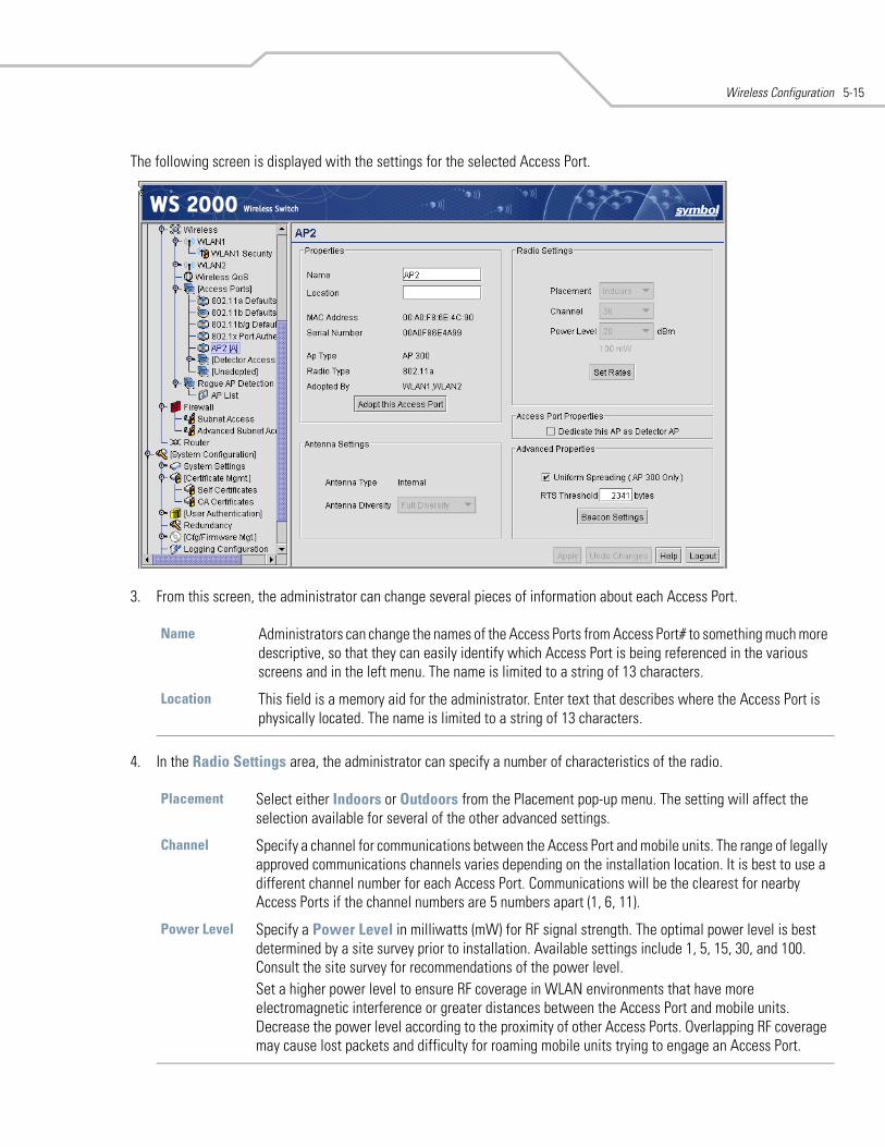
Wireless Configuration 5-15
The following screen is displayed with the settings for the selected Access Port.
3. From this screen, the administrator can change several pieces of information about each Access Port.
4. In the Radio Settings area, the administrator can specify a number of characteristics of the radio.
Name Administrators can change the names of the Access Ports from Access Port# to something much more descriptive, so that they can easily identify which Access Port is being referenced in the various screens and in the left menu. The name is limited to a string of 13 characters.
Location This field is a memory aid for the administrator. Enter text that describes where the Access Port is physically located. The name is limited to a string of 13 characters.
Placement Select either Indoors or Outdoors from the Placement pop-up menu. The setting will affect the selection available for several of the other advanced settings.
Channel Specify a channel for communications between the Access Port and mobile units. The range of legally approved communications channels varies depending on the installation location. It is best to use a different channel number for each Access Port. Communications will be the clearest for nearby Access Ports if the channel numbers are 5 numbers apart (1, 6, 11).
Power Level Specify a Power Level in milliwatts (mW) for RF signal strength. The optimal power level is best determined by a site survey prior to installation. Available settings include 1, 5, 15, 30, and 100. Consult the site survey for recommendations of the power level. Set a higher power level to ensure RF coverage in WLAN environments that have more electromagnetic interference or greater distances between the Access Port and mobile units. Decrease the power level according to the proximity of other Access Ports. Overlapping RF coverage may cause lost packets and difficulty for roaming mobile units trying to engage an Access Port.
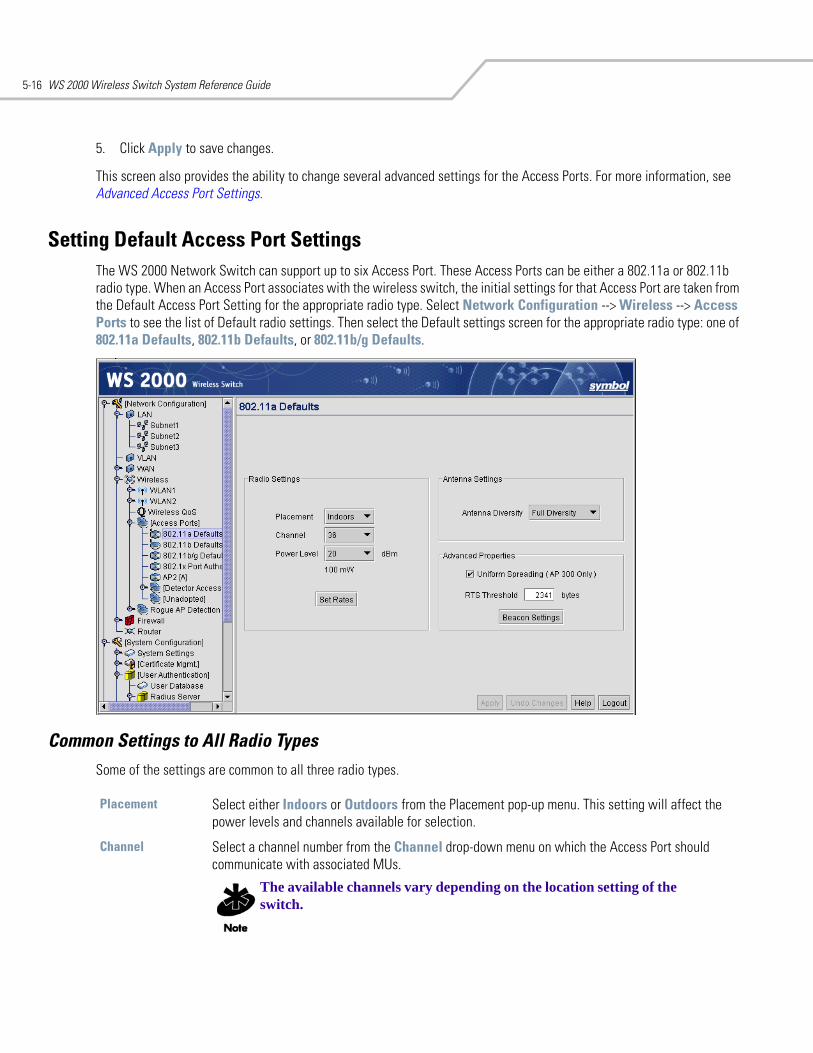
WS 2000 Wireless Switch System Reference Guide5-16
5. Click Apply to save changes.
This screen also provides the ability to change several advanced settings for the Access Ports. For more information, see Advanced Access Port Settings.
Setting Default Access Port SettingsThe WS 2000 Network Switch can support up to six Access Port. These Access Ports can be either a 802.11a or 802.11b radio type. When an Access Port associates with the wireless switch, the initial settings for that Access Port are taken from the Default Access Port Setting for the appropriate radio type. Select Network Configuration --> Wireless --> Access Ports to see the list of Default radio settings. Then select the Default settings screen for the appropriate radio type: one of 802.11a Defaults, 802.11b Defaults, or 802.11b/g Defaults.
Common Settings to All Radio Types Some of the settings are common to all three radio types.
Placement Select either Indoors or Outdoors from the Placement pop-up menu. This setting will affect the power levels and channels available for selection.
Channel Select a channel number from the Channel drop-down menu on which the Access Port should communicate with associated MUs.
The available channels vary depending on the location setting of the switch.
Wireless Configuration 5-17
Power Level Select a power level from the Power Level drop-down menu that will be used for radio communications between the Access Port and the MUs.Set a higher power level to ensure RF coverage in WLAN environments that have more electromagnetic interference or greater distances between the Access Port and mobile units (MUs). Decrease the power level according to the proximity of other Access Ports. Overlapping RF coverage may cause lost packets and difficulty for roaming MUs trying to engage an Access Port.
Antenna Diversity Use the drop-down menu to configure the Antenna Diversity settings for Access Ports that use external antennas.Full Diversity: Utilizes both antennas to provide antenna diversityPrimary Only: Enables only the primary antennaSecondary Only: Enables only the secondary antenna
Antenna Diversity should only be enabled if the Access Port has two matching external antennas.
RTS Threshold Set the Request to Send Threshold (RTS Threshold) by specifying a number. RTS is a transmitting station’s signal that requests a Clear To Send (CTS) response from a receiving station. This RTS/CTS procedure clears the air when many mobile units (MUs) are contending for transmission time. Modifying this value allows the administrator to control the number of data collisions and thereby enhance communication with nodes that are hard to find because of other active nodes in the transmission path.In this field, the administrator can specify a Request To Send (RTS) threshold (in bytes) for use by the WLAN’s adopted Access Ports. This setting initiates an RTS/CTS exchange for data frames that are larger than the threshold, and sends (without RTS/CTS) any data frames that are smaller than the threshold.Consider the tradeoffs when setting an appropriate RTS threshold for the WLAN’s Access Ports. A lower RTS threshold causes more frequent RTS/CTS exchanges. This consumes more bandwidth because of the additional latency (RTS/CTS exchanges) before transmissions can commence. A disadvantage is the reduction in data-frame throughput. An advantage is quicker system recovery from electromagnetic interference and data collisions. Environments with more wireless traffic and contention for transmission make the best use of a lower RTS threshold.A higher RTS threshold minimizes RTS/CTS exchanges, consuming less bandwidth for data transmissions. A disadvantage is less help to nodes that encounter interference and collisions. An advantage is faster data-frame throughput. Environments with less wireless traffic and contention for transmission make the best use of a higher RTS threshold.
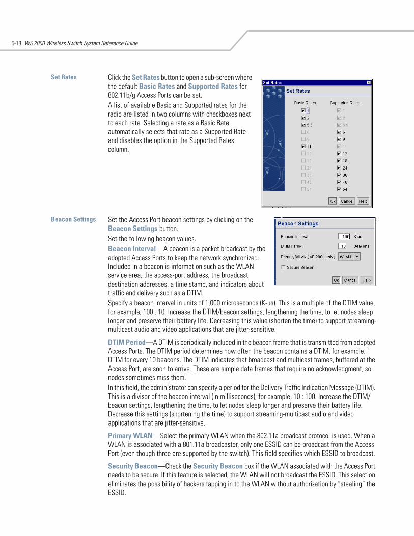
WS 2000 Wireless Switch System Reference Guide5-18
Set Rates Click the Set Rates button to open a sub-screen where the default Basic Rates and Supported Rates for 802.11b/g Access Ports can be set. A list of available Basic and Supported rates for the radio are listed in two columns with checkboxes next to each rate. Selecting a rate as a Basic Rate automatically selects that rate as a Supported Rate and disables the option in the Supported Rates column.
Beacon Settings Set the Access Port beacon settings by clicking on the Beacon Settings button.Set the following beacon values.Beacon Interval—A beacon is a packet broadcast by the adopted Access Ports to keep the network synchronized. Included in a beacon is information such as the WLAN service area, the access-port address, the broadcast destination addresses, a time stamp, and indicators about traffic and delivery such as a DTIM.Specify a beacon interval in units of 1,000 microseconds (K-us). This is a multiple of the DTIM value, for example, 100 : 10. Increase the DTIM/beacon settings, lengthening the time, to let nodes sleep longer and preserve their battery life. Decreasing this value (shorten the time) to support streaming-multicast audio and video applications that are jitter-sensitive.
DTIM Period—A DTIM is periodically included in the beacon frame that is transmitted from adopted Access Ports. The DTIM period determines how often the beacon contains a DTIM, for example, 1 DTIM for every 10 beacons. The DTIM indicates that broadcast and multicast frames, buffered at the Access Port, are soon to arrive. These are simple data frames that require no acknowledgment, so nodes sometimes miss them. In this field, the administrator can specify a period for the Delivery Traffic Indication Message (DTIM). This is a divisor of the beacon interval (in milliseconds); for example, 10 : 100. Increase the DTIM/beacon settings, lengthening the time, to let nodes sleep longer and preserve their battery life. Decrease this settings (shortening the time) to support streaming-multicast audio and video applications that are jitter-sensitive.
Primary WLAN—Select the primary WLAN when the 802.11a broadcast protocol is used. When a WLAN is associated with a 801.11a broadcaster, only one ESSID can be broadcast from the Access Port (even though three are supported by the switch). This field specifies which ESSID to broadcast.
Security Beacon—Check the Security Beacon box if the WLAN associated with the Access Port needs to be secure. If this feature is selected, the WLAN will not broadcast the ESSID. This selection eliminates the possibility of hackers tapping in to the WLAN without authorization by “stealing” the ESSID.
Wireless Configuration 5-19
Radio-Specific SettingsThe fields below are only available for some radio types, as indicated in the second column.
Click the Apply button to save changes.
Advanced Access Port SettingsThe WS 2000 Wireless Switch GUI allows the administrator to configure the Access Port settings. To examine or change that information:
1. Select Network Configuration --> Wireless --> Access Ports from the left menu and then click the + to the left of the menu item. The detected Access Ports will be listed under the menu item.
Uniform Spreading (only AP 300)
a Check this checkbox to enable the Uniform Spreading feature of the AP 300. To comply with Dynamic Frequency Selection (DFS) requirements in the European Union, the 802.11a radio on AP 300 Access Ports will come up on a random channel each time it is powered on.
To change the channel on the 802.11a radio for an AP 300 Access Port, this box MUST be unchecked.
Support Short Preamble
b/g Check the Support Short Preamble box to allow the Access Port to communicate with the MUs using a short 56-bit preamble. A preamble is the beginning part of a frame. The preamble comprises such elements as robust carrier sensing, collision detection, equalizer training, timing recovery, and gain adjustment. The administration can choose between a long or short preamble for data-frame transmission from the WLAN’s adopted Access Ports.Use the long preamble setting (the default) for legacy wireless equipment that is not capable of dealing with short preambles. Use the short preamble setting where legacy equipment is not an issue and maximum throughput is desired, for example when streaming video or Voice-over-IP applications are used.
802.11 b/g mode b/g Use this menu to set radio rates on the Access Port to one of the following settings:B and G: Clients that support 802.11b and/or 802.11g rates may associate with the Access Port.G only: Only clients that support 802.11g rates may associate with the Access Port.B only: Only clients that support 802.11b rates may associate with the Access Port.
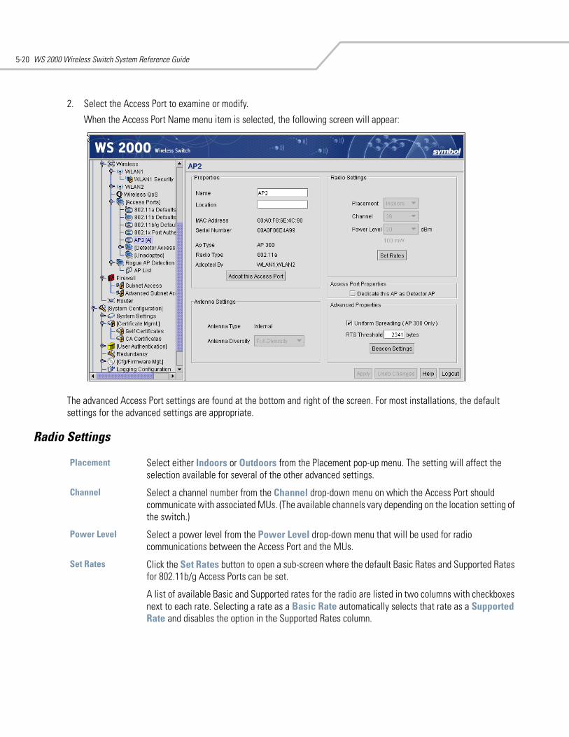
WS 2000 Wireless Switch System Reference Guide5-20
2. Select the Access Port to examine or modify.
When the Access Port Name menu item is selected, the following screen will appear:
The advanced Access Port settings are found at the bottom and right of the screen. For most installations, the default settings for the advanced settings are appropriate.
Radio Settings
Placement Select either Indoors or Outdoors from the Placement pop-up menu. The setting will affect the selection available for several of the other advanced settings.
Channel Select a channel number from the Channel drop-down menu on which the Access Port should communicate with associated MUs. (The available channels vary depending on the location setting of the switch.)
Power Level Select a power level from the Power Level drop-down menu that will be used for radio communications between the Access Port and the MUs.
Set Rates Click the Set Rates button to open a sub-screen where the default Basic Rates and Supported Rates for 802.11b/g Access Ports can be set.
A list of available Basic and Supported rates for the radio are listed in two columns with checkboxes next to each rate. Selecting a rate as a Basic Rate automatically selects that rate as a Supported Rate and disables the option in the Supported Rates column.
Wireless Configuration 5-21
Antenna Settings
Advanced Properties
Internal/External Antenna
Specify whether the Access Port has internal antenna or external antenna. Depending on the antenna type selected certain options in the Radio Settings section may be disabled.
Antenna Diversity Use the drop-down menu to configure the Antenna Diversity settings for Access Ports that use external antennas.Full Diversity: Utilizes both antennas to provide antenna diversity.Primary Only: Enables only the primary antenna.Secondary Only: Enables only the secondary antenna.
Antenna Diversity should only be enabled if the Access Port has two matching external antennas.
Support Short Preamble
Check the Support Short Preamble checkbox to allow the Access Port to communicate with the MUs using a short 56-bit preamble. A preamble is the beginning part of a frame. The preamble comprises such elements as robust carrier sensing, collision detection, equalizer training, timing recovery, and gain adjustment. The administration can choose between a long or short preamble for data-frame transmission from the WLAN’s adopted Access Ports.Use the long preamble setting (the default) for legacy wireless equipment that is not capable of dealing with short preambles. Use the short preamble setting where legacy equipment is not an issue and maximum throughput is desired, for example when streaming video or Voice-over-IP applications are used.
RTS Threshold Set the Request to Send Threshold (RTS Threshold) by specifying a number. RTS is a transmitting station’s signal that requests a Clear To Send (CTS) response from a receiving station. This RTS/CTS procedure clears the air when many mobile units (MUs) are contending for transmission time. Modifying this value allows the administrator to control the number of data collisions and thereby enhance communication with nodes that are hard to find because of other active nodes in the transmission path.In this field, the administrator can specify a Request To Send (RTS) threshold (in bytes) for use by the WLAN’s adopted Access Ports. This setting initiates an RTS/CTS exchange for data frames that are larger than the threshold, and sends (without RTS/CTS) any data frames that are smaller than the threshold.Consider the tradeoffs when setting an appropriate RTS threshold for the WLAN’s Access Ports. A lower RTS threshold causes more frequent RTS/CTS exchanges. This consumes more bandwidth because of the additional latency (RTS/CTS exchanges) before transmissions can commence. A disadvantage is the reduction in data-frame throughput. An advantage is quicker system recovery from electromagnetic interference and data collisions. Environments with more wireless traffic and contention for transmission make the best use of a lower RTS threshold.
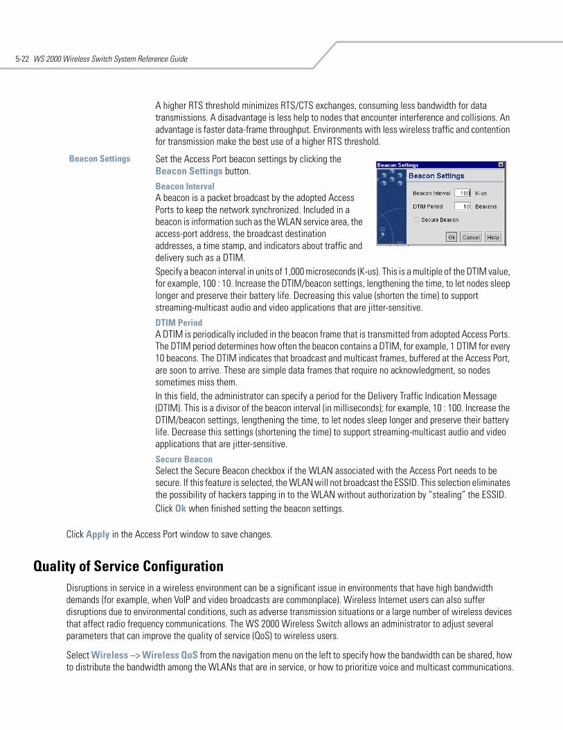
WS 2000 Wireless Switch System Reference Guide5-22
Click Apply in the Access Port window to save changes.
Quality of Service ConfigurationDisruptions in service in a wireless environment can be a significant issue in environments that have high bandwidth demands (for example, when VoIP and video broadcasts are commonplace). Wireless Internet users can also suffer disruptions due to environmental conditions, such as adverse transmission situations or a large number of wireless devices that affect radio frequency communications. The WS 2000 Wireless Switch allows an administrator to adjust several parameters that can improve the quality of service (QoS) to wireless users.
Select Wireless --> Wireless QoS from the navigation menu on the left to specify how the bandwidth can be shared, how to distribute the bandwidth among the WLANs that are in service, or how to prioritize voice and multicast communications.
A higher RTS threshold minimizes RTS/CTS exchanges, consuming less bandwidth for data transmissions. A disadvantage is less help to nodes that encounter interference and collisions. An advantage is faster data-frame throughput. Environments with less wireless traffic and contention for transmission make the best use of a higher RTS threshold.
Beacon Settings Set the Access Port beacon settings by clicking the Beacon Settings button. Beacon IntervalA beacon is a packet broadcast by the adopted Access Ports to keep the network synchronized. Included in a beacon is information such as the WLAN service area, the access-port address, the broadcast destination addresses, a time stamp, and indicators about traffic and delivery such as a DTIM.Specify a beacon interval in units of 1,000 microseconds (K-us). This is a multiple of the DTIM value, for example, 100 : 10. Increase the DTIM/beacon settings, lengthening the time, to let nodes sleep longer and preserve their battery life. Decreasing this value (shorten the time) to support streaming-multicast audio and video applications that are jitter-sensitive. DTIM Period A DTIM is periodically included in the beacon frame that is transmitted from adopted Access Ports. The DTIM period determines how often the beacon contains a DTIM, for example, 1 DTIM for every 10 beacons. The DTIM indicates that broadcast and multicast frames, buffered at the Access Port, are soon to arrive. These are simple data frames that require no acknowledgment, so nodes sometimes miss them. In this field, the administrator can specify a period for the Delivery Traffic Indication Message (DTIM). This is a divisor of the beacon interval (in milliseconds); for example, 10 : 100. Increase the DTIM/beacon settings, lengthening the time, to let nodes sleep longer and preserve their battery life. Decrease this settings (shortening the time) to support streaming-multicast audio and video applications that are jitter-sensitive.
Secure Beacon Select the Secure Beacon checkbox if the WLAN associated with the Access Port needs to be secure. If this feature is selected, the WLAN will not broadcast the ESSID. This selection eliminates the possibility of hackers tapping in to the WLAN without authorization by “stealing” the ESSID. Click Ok when finished setting the beacon settings.
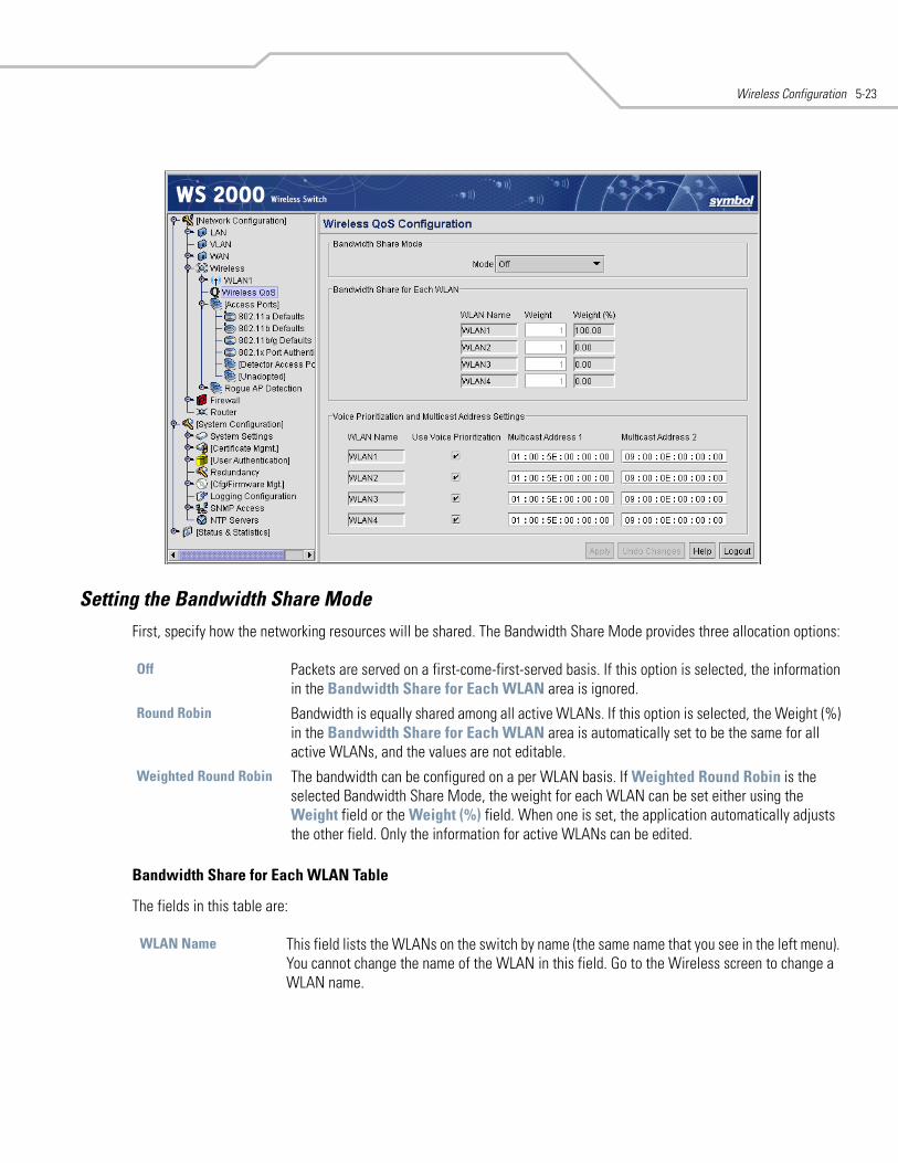
Wireless Configuration 5-23
Setting the Bandwidth Share ModeFirst, specify how the networking resources will be shared. The Bandwidth Share Mode provides three allocation options:
Bandwidth Share for Each WLAN Table
The fields in this table are:
Off Packets are served on a first-come-first-served basis. If this option is selected, the information in the Bandwidth Share for Each WLAN area is ignored.
Round Robin Bandwidth is equally shared among all active WLANs. If this option is selected, the Weight (%) in the Bandwidth Share for Each WLAN area is automatically set to be the same for all active WLANs, and the values are not editable.
Weighted Round Robin The bandwidth can be configured on a per WLAN basis. If Weighted Round Robin is the selected Bandwidth Share Mode, the weight for each WLAN can be set either using the Weight field or the Weight (%) field. When one is set, the application automatically adjusts the other field. Only the information for active WLANs can be edited.
WLAN Name This field lists the WLANs on the switch by name (the same name that you see in the left menu). You cannot change the name of the WLAN in this field. Go to the Wireless screen to change a WLAN name.
WS 2000 Wireless Switch System Reference Guide5-24
Configuring Voice Prioritization and Multicast Address SettingsTo ensure better performance with Voice over IP (VoIP) broadcasts, the administrator can enable voice prioritization for particular multicast addresses within a WLAN. In the table, specify the multicast addresses by filling out the fields:
Voice prioritization and multicast addressing will only affect active WLANs. Applying these settings to a inactive WLAN will have no effect. To make a WLAN active, go to the Wireless screen.
Setting Up Port Authentication for AP 300 Access Ports802.1x port authentication is used to provide security and authentication for all wired clients on a WLAN. The WS 2000 Wireless Switch supports 802.1x port authentication for the AP 300 Access Ports connected to it. It uses a username and password for all ports that can be configured from the wireless switch.
Select Network Configuration --> [Access Ports] --> 802.1x Port Authentication from the navigation menu on the left.
Weight The Weight field specifies the relative amount of bandwidth provided to the given WLAN as compared to the other WLANs. For example, if WLAN1 has Weight set to 3 and WLAN2 has Weight set to 1, WLAN1 will get 3 times as much bandwidth as WLAN2. When the Weight field is changed, the weight percentage adjusts automatically to match.
Weight (%) This field is automatically calculated and cannot be edited. This field specifies the percentage of bandwidth allocated for each of the WLANs. If the Bandwidth Share Mode is set to Round Robin, the Weight (%) will be the same for all active WLANs. If the Bandwidth Share Mode is set to Weighted Round Robin, the value is calculated based upon the Weights set for each of the WLANs. For example, if WLAN1 has Weight set to 3 and WLAN2 has Weight set to 1, the application will automatically set the weight percentage to 75% for WLAN1 and 25% for WLAN2.
WLAN Name This field lists the WLANs on the switch by name (the same name that you see in the left menu). You cannot change the name of the WLAN in this field. Go to the Wireless screen to change a WLAN name.
Use Voice Prioritization Check this box to enable prioritization of voice over data for RF transmissions for the associated WLAN. This setting reduces the latency that might occur when data transmissions and VoIP transmissions compete for the same resources. Latency is usually experienced as broken or delayed speech or sound.
Multicast Address #1 and Multicast Address #2
Use the two Multicast Address fields to specify one or two MAC addresses to be used for multicast applications. Some VoIP devices make use of multicast addresses. Using this mechanism ensures that the multicast packets for these devices are not delayed by the packet queue.
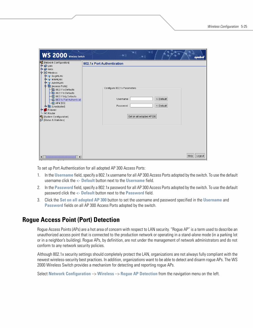
Wireless Configuration 5-25
To set up Port Authentication for all adopted AP 300 Access Ports:
1. In the Username field, specify a 802.1x username for all AP 300 Access Ports adopted by the switch. To use the default username click the <- Default button next to the Username field.
2. In the Password field, specify a 802.1x password for all AP 300 Access Ports adopted by the switch. To use the default password click the <- Default button next to the Password field.
3. Click the Set on all adopted AP 300 button to set the username and password specified in the Username and Password fields on all AP 300 Access Ports adopted by the switch.
Rogue Access Point (Port) DetectionRogue Access Points (APs) are a hot area of concern with respect to LAN security. “Rogue AP” is a term used to describe an unauthorized access point that is connected to the production network or operating in a stand-alone mode (in a parking lot or in a neighbor’s building). Rogue APs, by definition, are not under the management of network administrators and do not conform to any network security policies.
Although 802.1x security settings should completely protect the LAN, organizations are not always fully compliant with the newest wireless-security best practices. In addition, organizations want to be able to detect and disarm rogue APs. The WS 2000 Wireless Switch provides a mechanism for detecting and reporting rogue APs.
Select Network Configuration --> Wireless --> Rogue AP Detection from the navigation menu on the left.
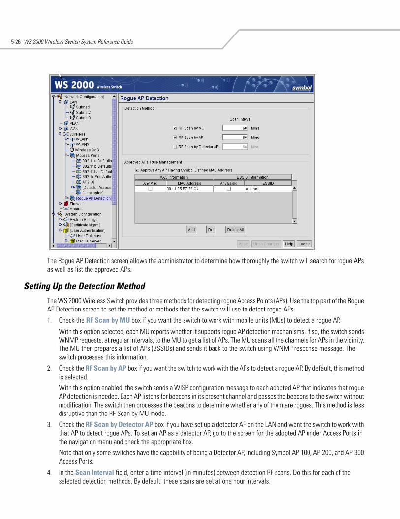
WS 2000 Wireless Switch System Reference Guide5-26
The Rogue AP Detection screen allows the administrator to determine how thoroughly the switch will search for rogue APs as well as list the approved APs.
Setting Up the Detection MethodThe WS 2000 Wireless Switch provides three methods for detecting rogue Access Points (APs). Use the top part of the Rogue AP Detection screen to set the method or methods that the switch will use to detect rogue APs.
1. Check the RF Scan by MU box if you want the switch to work with mobile units (MUs) to detect a rogue AP.
With this option selected, each MU reports whether it supports rogue AP detection mechanisms. If so, the switch sends WNMP requests, at regular intervals, to the MU to get a list of APs. The MU scans all the channels for APs in the vicinity. The MU then prepares a list of APs (BSSIDs) and sends it back to the switch using WNMP response message. The switch processes this information.
2. Check the RF Scan by AP box if you want the switch to work with the APs to detect a rogue AP. By default, this method is selected.
With this option enabled, the switch sends a WISP configuration message to each adopted AP that indicates that rogue AP detection is needed. Each AP listens for beacons in its present channel and passes the beacons to the switch without modification. The switch then processes the beacons to determine whether any of them are rogues. This method is less disruptive than the RF Scan by MU mode.
3. Check the RF Scan by Detector AP box if you have set up a detector AP on the LAN and want the switch to work with that AP to detect rogue APs. To set an AP as a detector AP, go to the screen for the adopted AP under Access Ports in the navigation menu and check the appropriate box.
Note that only some switches have the capability of being a Detector AP, including Symbol AP 100, AP 200, and AP 300 Access Ports.
4. In the Scan Interval field, enter a time interval (in minutes) between detection RF scans. Do this for each of the selected detection methods. By default, these scans are set at one hour intervals.
Wireless Configuration 5-27
Defining and Maintaining Approved AP List RulesThe lower half of the Rogue AP Detection screen specifies rules that determine whether a detected AP can be approved or not. Each entry in the table works as an AP evaluation rule. You can specify a particular MAC address or a particular ESSID, or you can indicate that any MAC address or ESSID will work. However, if you select Any MAC and Any ESSID on the same line, all APs will be approved. Up to 20 rules can be defined.
1. Check the Approve Any AP Having a Symbol Defined MAC Address box to indicate that any Symbol AP (that is, one that has a known Symbol MAC address) is an approved AP.
2. Click the Add button to add a line in the rule table and then fill out the following table cells:
3. To delete a particular rule from the table, select the rule and then click the Del button.
4. Click the Delete All button to clear the entire rule list.
Examine the Approve and Rogue Access PortsThis screen displays information about APs known to the switch. All approved APs are listed in the upper table. All rogue APs are listed in the lower table. This screen also allows the administrator to create detection rules from the information collected about approved or rogue APs.
To maintain the lists, select Network Configuration --> Wireless --> Rogue AP Detection --> AP List from the navigation menu on the left.
Any MAC Check this box to indicate that an AP with any MAC address matches the rule.
MAC Address Enter an approved MAC address to be used during the detection process. This field is only used when Any MAC (on the same line) is not checked.
Any ESSID Check this box to indicate that an AP with any ESSID matches the rule.
ESSID Enter an approved ESSID to be used during the detection process. This field is only used when Any ESSID (on the same line) is not checked.
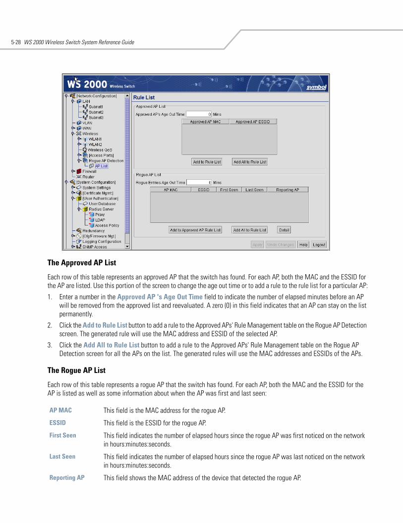
WS 2000 Wireless Switch System Reference Guide5-28
The Approved AP List
Each row of this table represents an approved AP that the switch has found. For each AP, both the MAC and the ESSID for the AP are listed. Use this portion of the screen to change the age out time or to add a rule to the rule list for a particular AP:
1. Enter a number in the Approved AP 's Age Out Time field to indicate the number of elapsed minutes before an AP will be removed from the approved list and reevaluated. A zero (0) in this field indicates that an AP can stay on the list permanently.
2. Click the Add to Rule List button to add a rule to the Approved APs' Rule Management table on the Rogue AP Detection screen. The generated rule will use the MAC address and ESSID of the selected AP.
3. Click the Add All to Rule List button to add a rule to the Approved APs' Rule Management table on the Rogue AP Detection screen for all the APs on the list. The generated rules will use the MAC addresses and ESSIDs of the APs.
The Rogue AP List
Each row of this table represents a rogue AP that the switch has found. For each AP, both the MAC and the ESSID for the AP is listed as well as some information about when the AP was first and last seen:
AP MAC This field is the MAC address for the rogue AP.
ESSID This field is the ESSID for the rogue AP.
First Seen This field indicates the number of elapsed hours since the rogue AP was first noticed on the network in hours:minutes:seconds.
Last Seen This field indicates the number of elapsed hours since the rogue AP was last noticed on the network in hours:minutes:seconds.
Reporting AP This field shows the MAC address of the device that detected the rogue AP.
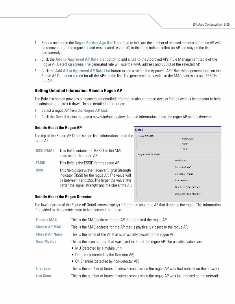
Wireless Configuration 5-29
1. Enter a number in the Rogue Entries Age Out Time field to indicate the number of elapsed minutes before an AP will be removed from the rogue list and reevaluated. A zero (0) in this field indicates that an AP can stay on the list permanently.
2. Click the Add to Approved AP Rule List button to add a rule to the Approved APs' Rule Management table of the Rogue AP Detection screen. The generated rule will use the MAC address and ESSID of the selected AP.
3. Click the Add All to Approved AP Rule List button to add a rule to the Approved APs' Rule Management table on the Rogue AP Detection screen for all the APs on the list. The generated rules will use the MAC addresses and ESSIDs of the APs.
Getting Detailed Information About a Rogue AP
The Rule List screen provides a means to get detailed information about a rogue Access Port as well as its detector to help an administrator track it down. To see detailed information:
1. Select a rogue AP from the Rogue AP List.
2. Click the Detail button to open a new window to view detailed information about the rogue AP and its detector.
Details About the Rogue AP
The top of the Rogue AP Detail screen lists information about the rogue AP:
Details About the Rogue Detector
The lower portion of the Rogue AP Detail screen displays information about the AP that detected the rogue. This information if provided to the administrator to help located the rogue.
BSSID/MAC This field contains the BSSID or the MAC address for the rogue AP.
ESSID This field is the ESSID for the rogue AP.
RSSI This field displays the Receiver Signal Strength Indicator (RSSI) for the rogue AP. The value will be between 1 and 255. The larger the value, the better the signal strength and the closer the AP.
Finder's MAC This is the MAC address for the AP that detected the rogue AP.
Closest AP MAC This is the MAC address for the AP that is physically closest to the rogue AP.
Closest AP Name This is the name of the AP that is physically closest to the rogue AP.
Scan Method This is the scan method that was used to detect the rogue AP. The possible values are:
• MU (detected by a mobile unit)
• Detector (detected by the Detector AP)
• On Channel (detected by non-detector AP)
First Seen This is the number of hours:minutes:seconds since the rogue AP was first noticed on the network.
Last Seen This is the number of hours:minutes:seconds since the rogue AP was last noticed on the network.
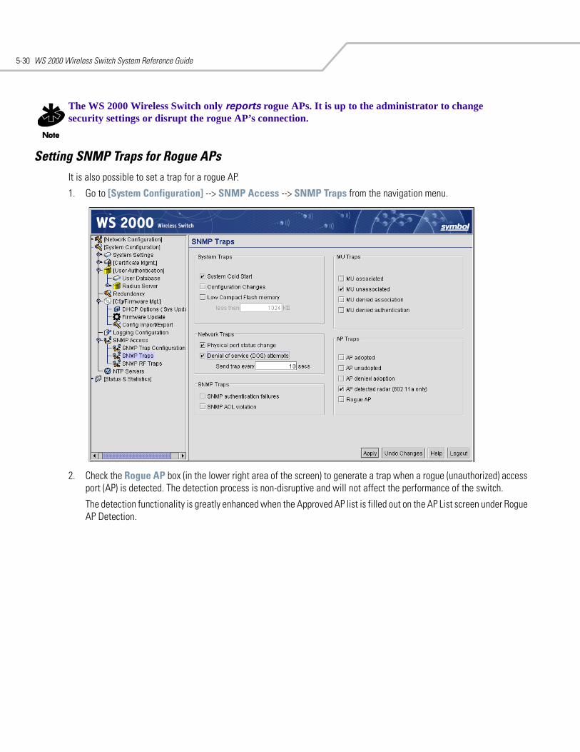
WS 2000 Wireless Switch System Reference Guide5-30
The WS 2000 Wireless Switch only reports rogue APs. It is up to the administrator to change security settings or disrupt the rogue AP’s connection.
Setting SNMP Traps for Rogue APsIt is also possible to set a trap for a rogue AP.
1. Go to [System Configuration] --> SNMP Access --> SNMP Traps from the navigation menu.
2. Check the Rogue AP box (in the lower right area of the screen) to generate a trap when a rogue (unauthorized) access port (AP) is detected. The detection process is non-disruptive and will not affect the performance of the switch.
The detection functionality is greatly enhanced when the Approved AP list is filled out on the AP List screen under Rogue AP Detection.
6Administrator and User Access
Configuring Administrator Access . . . . . . . . . . . . . . . . . . . . . . . . . . . . . . . . . . . . . . . . . . . . . . . . . . . . . . . . . . . . 6-2Selecting the Type of Admin Access . . . . . . . . . . . . . . . . . . . . . . . . . . . . . . . . . . . . . . . . . . . . . . . . . . . . . . 6-2Configuring Secure Shell Connection Parameters. . . . . . . . . . . . . . . . . . . . . . . . . . . . . . . . . . . . . . . . . . . . 6-3Admin Authentication and RADIUS Server Authentication Setup . . . . . . . . . . . . . . . . . . . . . . . . . . . . . . . 6-3Setting Up AirBEAM Software Access . . . . . . . . . . . . . . . . . . . . . . . . . . . . . . . . . . . . . . . . . . . . . . . . . . . . 6-3Applet Timeout Specification . . . . . . . . . . . . . . . . . . . . . . . . . . . . . . . . . . . . . . . . . . . . . . . . . . . . . . . . . . . 6-3Changing the Administrator Password . . . . . . . . . . . . . . . . . . . . . . . . . . . . . . . . . . . . . . . . . . . . . . . . . . . . 6-4
Configuring User Authentication . . . . . . . . . . . . . . . . . . . . . . . . . . . . . . . . . . . . . . . . . . . . . . . . . . . . . . . . . . . . . 6-4Configuring the RADIUS Server . . . . . . . . . . . . . . . . . . . . . . . . . . . . . . . . . . . . . . . . . . . . . . . . . . . . . . . . . . 6-5Configuring Lightweight Directory Access Protocol (LDAP) Authentication . . . . . . . . . . . . . . . . . . . . . . . . 6-6Setting Up a Proxy RADIUS Server . . . . . . . . . . . . . . . . . . . . . . . . . . . . . . . . . . . . . . . . . . . . . . . . . . . . . . . 6-7Managing the Local User Database . . . . . . . . . . . . . . . . . . . . . . . . . . . . . . . . . . . . . . . . . . . . . . . . . . . . . . 6-8Setting the User Access Policy . . . . . . . . . . . . . . . . . . . . . . . . . . . . . . . . . . . . . . . . . . . . . . . . . . . . . . . . . 6-10
Managing Digital Certificates . . . . . . . . . . . . . . . . . . . . . . . . . . . . . . . . . . . . . . . . . . . . . . . . . . . . . . . . . . . . . . 6-11Importing CA Certificates. . . . . . . . . . . . . . . . . . . . . . . . . . . . . . . . . . . . . . . . . . . . . . . . . . . . . . . . . . . . . . 6-11Creating Self Certificates. . . . . . . . . . . . . . . . . . . . . . . . . . . . . . . . . . . . . . . . . . . . . . . . . . . . . . . . . . . . . . 6-12
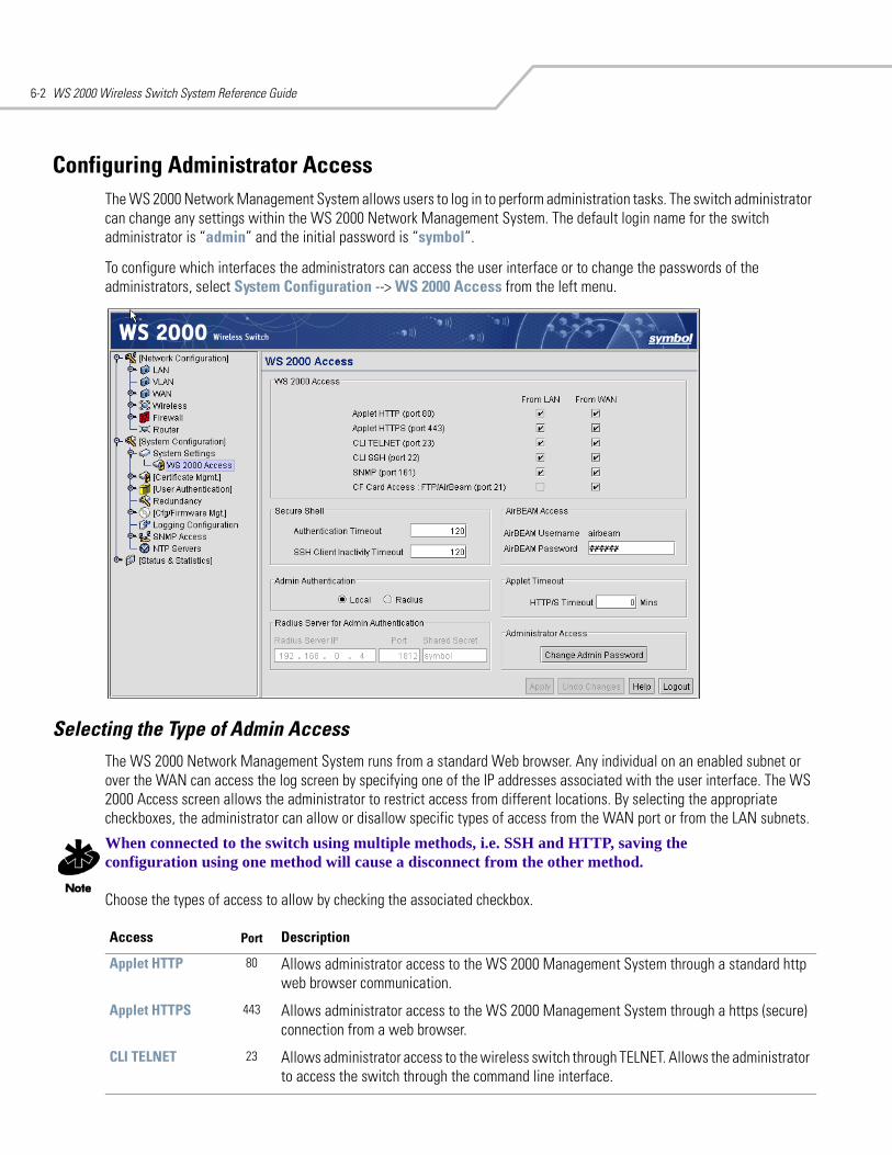
WS 2000 Wireless Switch System Reference Guide6-2
Configuring Administrator AccessThe WS 2000 Network Management System allows users to log in to perform administration tasks. The switch administrator can change any settings within the WS 2000 Network Management System. The default login name for the switch administrator is “admin” and the initial password is “symbol”.
To configure which interfaces the administrators can access the user interface or to change the passwords of the administrators, select System Configuration --> WS 2000 Access from the left menu.
Selecting the Type of Admin Access The WS 2000 Network Management System runs from a standard Web browser. Any individual on an enabled subnet or over the WAN can access the log screen by specifying one of the IP addresses associated with the user interface. The WS 2000 Access screen allows the administrator to restrict access from different locations. By selecting the appropriate checkboxes, the administrator can allow or disallow specific types of access from the WAN port or from the LAN subnets.
When connected to the switch using multiple methods, i.e. SSH and HTTP, saving the configuration using one method will cause a disconnect from the other method.
Choose the types of access to allow by checking the associated checkbox.
Access Port Description
Applet HTTP 80 Allows administrator access to the WS 2000 Management System through a standard http web browser communication.
Applet HTTPS 443 Allows administrator access to the WS 2000 Management System through a https (secure) connection from a web browser.
CLI TELNET 23 Allows administrator access to the wireless switch through TELNET. Allows the administrator to access the switch through the command line interface.
Administrator and User Access 6-3
If all the checkboxes in this section are disabled, the administrator will not be able to access the switch through the WS 2000 Management System user interface. The only access available is through a direct serial cable connection from a PC. All commands are given using the command line interface. If this situation occurs accidentally, you can restore the switch’s factory settings using the command line interface.
Configuring Secure Shell Connection ParametersIf CLI SSH (port 22) is enabled either for either WAN or LAN, set the fields in the Secure Shell area:
1. Enter a value, in seconds, when a client connected via SSH must reauthenticate in the Authentication Timeout field. The default is 120 seconds (2 minutes).
2. Enter the amount of time, in seconds, when an inactive client using SSH will be disconnected in the SSH Client Inactivity Timeout field. The default is 120 seconds (2 minutes).
Admin Authentication and RADIUS Server Authentication SetupThere are two methods available for authenticating administrators upon contacting the switch. This area provides a means to set up the desired authentication methods.
1. First choose an authentication method:
• Select the Local radio button to have the administrator of the switch authenticate using the built-in password authentication process (that is, using the standard admin password).
• Select the Radius radio button to have the administrator authenticate against a RADIUS database. If RADIUS is selected, the RADIUS server information can be entered in the Radius Server for Admin Authentication area.
2. If the Radius button is selected, specify the Radius Server IP address, the communication port for the authentication process, and the RADIUS server’s Shared Secret (password) that should be used.
Setting Up AirBEAM Software AccessSymbol’s AirBEAM software suite is a comprehensive set of mobility management tools that maximize the availability, security and effectiveness of a wireless network. The fields in this section of the screen allow the administrator to enable access from the AirBEAM software suite and to set the AirBEAM password.
1. To enable AirBEAM access, check the Enable AirBEAM checkbox.
2. Specify a password for AirBEAM software access. Note that the AirBEAM login name is always “airbeam”.
3. Click the Apply button to save changes.
CLI SSH 22 Allows administrator access to the command line interface of the wireless switch through the Secure Shell (SSH) protocol of TCP/IP.
SNMP 161 Allows administrator access to change switch settings from an SNMP server.
CF Card Access: FTP/AirBeam
21 Allows administrator access with AirBEAM using FTP to upload and download configuration data, firmware, and other software to/from the switch's CF card. The username and password used for AirBEAM is configured in the AirBEAM Access section of the screen.
Access Port Description
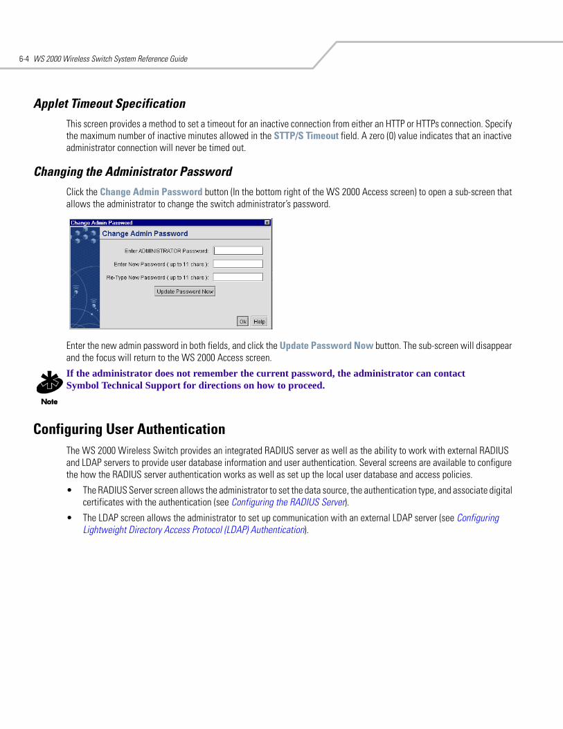
WS 2000 Wireless Switch System Reference Guide6-4
Applet Timeout SpecificationThis screen provides a method to set a timeout for an inactive connection from either an HTTP or HTTPs connection. Specify the maximum number of inactive minutes allowed in the STTP/S Timeout field. A zero (0) value indicates that an inactive administrator connection will never be timed out.
Changing the Administrator PasswordClick the Change Admin Password button (In the bottom right of the WS 2000 Access screen) to open a sub-screen that allows the administrator to change the switch administrator’s password.
Enter the new admin password in both fields, and click the Update Password Now button. The sub-screen will disappear and the focus will return to the WS 2000 Access screen.
If the administrator does not remember the current password, the administrator can contact Symbol Technical Support for directions on how to proceed.
Configuring User AuthenticationThe WS 2000 Wireless Switch provides an integrated RADIUS server as well as the ability to work with external RADIUS and LDAP servers to provide user database information and user authentication. Several screens are available to configure the how the RADIUS server authentication works as well as set up the local user database and access policies.
• The RADIUS Server screen allows the administrator to set the data source, the authentication type, and associate digital certificates with the authentication (see Configuring the RADIUS Server).
• The LDAP screen allows the administrator to set up communication with an external LDAP server (see Configuring Lightweight Directory Access Protocol (LDAP) Authentication).
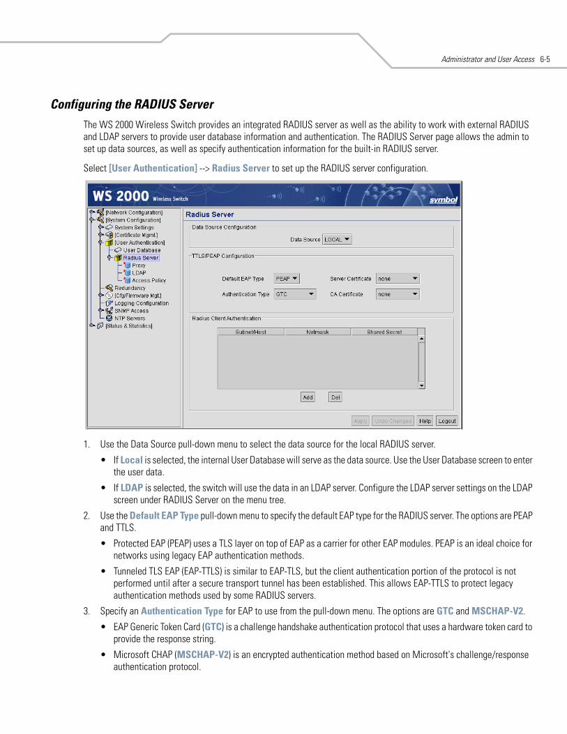
Administrator and User Access 6-5
Configuring the RADIUS ServerThe WS 2000 Wireless Switch provides an integrated RADIUS server as well as the ability to work with external RADIUS and LDAP servers to provide user database information and authentication. The RADIUS Server page allows the admin to set up data sources, as well as specify authentication information for the built-in RADIUS server.
Select [User Authentication] --> Radius Server to set up the RADIUS server configuration.
1. Use the Data Source pull-down menu to select the data source for the local RADIUS server.
• If Local is selected, the internal User Database will serve as the data source. Use the User Database screen to enter the user data.
• If LDAP is selected, the switch will use the data in an LDAP server. Configure the LDAP server settings on the LDAP screen under RADIUS Server on the menu tree.
2. Use the Default EAP Type pull-down menu to specify the default EAP type for the RADIUS server. The options are PEAP and TTLS.
• Protected EAP (PEAP) uses a TLS layer on top of EAP as a carrier for other EAP modules. PEAP is an ideal choice for networks using legacy EAP authentication methods.
• Tunneled TLS EAP (EAP-TTLS) is similar to EAP-TLS, but the client authentication portion of the protocol is not performed until after a secure transport tunnel has been established. This allows EAP-TTLS to protect legacy authentication methods used by some RADIUS servers.
3. Specify an Authentication Type for EAP to use from the pull-down menu. The options are GTC and MSCHAP-V2.
• EAP Generic Token Card (GTC) is a challenge handshake authentication protocol that uses a hardware token card to provide the response string.
• Microsoft CHAP (MSCHAP-V2) is an encrypted authentication method based on Microsoft's challenge/response authentication protocol.
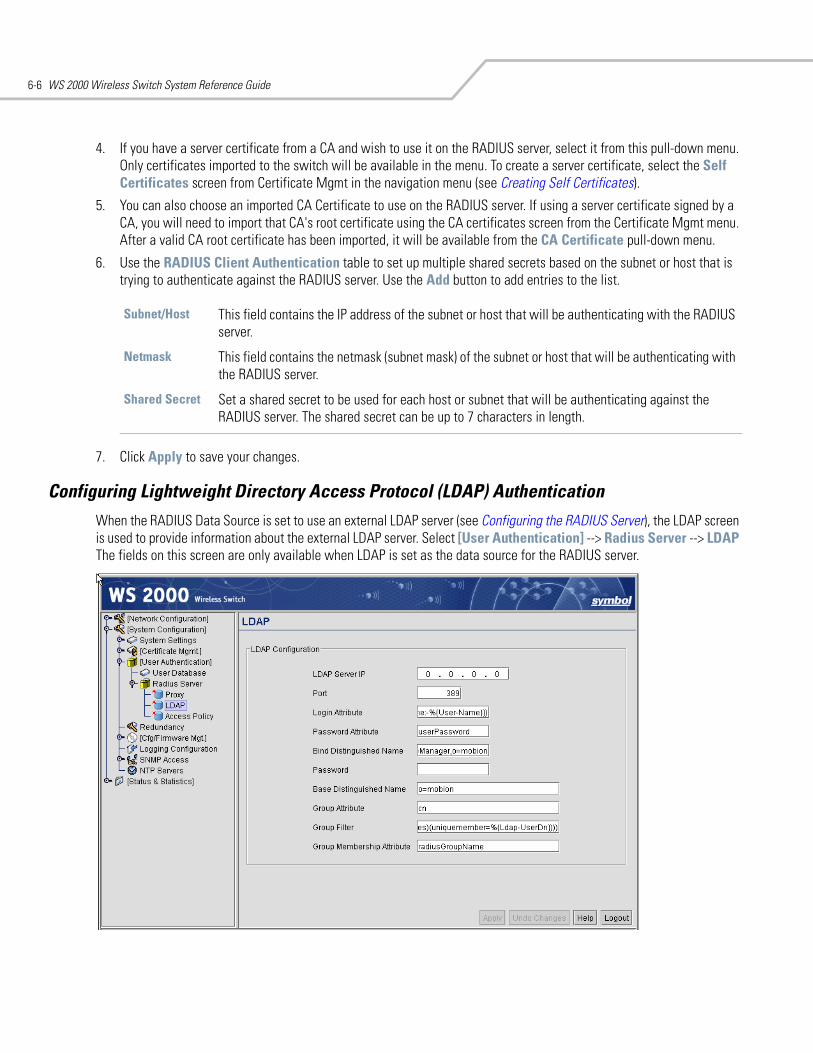
WS 2000 Wireless Switch System Reference Guide6-6
4. If you have a server certificate from a CA and wish to use it on the RADIUS server, select it from this pull-down menu. Only certificates imported to the switch will be available in the menu. To create a server certificate, select the Self Certificates screen from Certificate Mgmt in the navigation menu (see Creating Self Certificates).
5. You can also choose an imported CA Certificate to use on the RADIUS server. If using a server certificate signed by a CA, you will need to import that CA's root certificate using the CA certificates screen from the Certificate Mgmt menu. After a valid CA root certificate has been imported, it will be available from the CA Certificate pull-down menu.
6. Use the RADIUS Client Authentication table to set up multiple shared secrets based on the subnet or host that is trying to authenticate against the RADIUS server. Use the Add button to add entries to the list.
7. Click Apply to save your changes.
Configuring Lightweight Directory Access Protocol (LDAP) AuthenticationWhen the RADIUS Data Source is set to use an external LDAP server (see Configuring the RADIUS Server), the LDAP screen is used to provide information about the external LDAP server. Select [User Authentication] --> Radius Server --> LDAP The fields on this screen are only available when LDAP is set as the data source for the RADIUS server.
Subnet/Host This field contains the IP address of the subnet or host that will be authenticating with the RADIUS server.
Netmask This field contains the netmask (subnet mask) of the subnet or host that will be authenticating with the RADIUS server.
Shared Secret Set a shared secret to be used for each host or subnet that will be authenticating against the RADIUS server. The shared secret can be up to 7 characters in length.
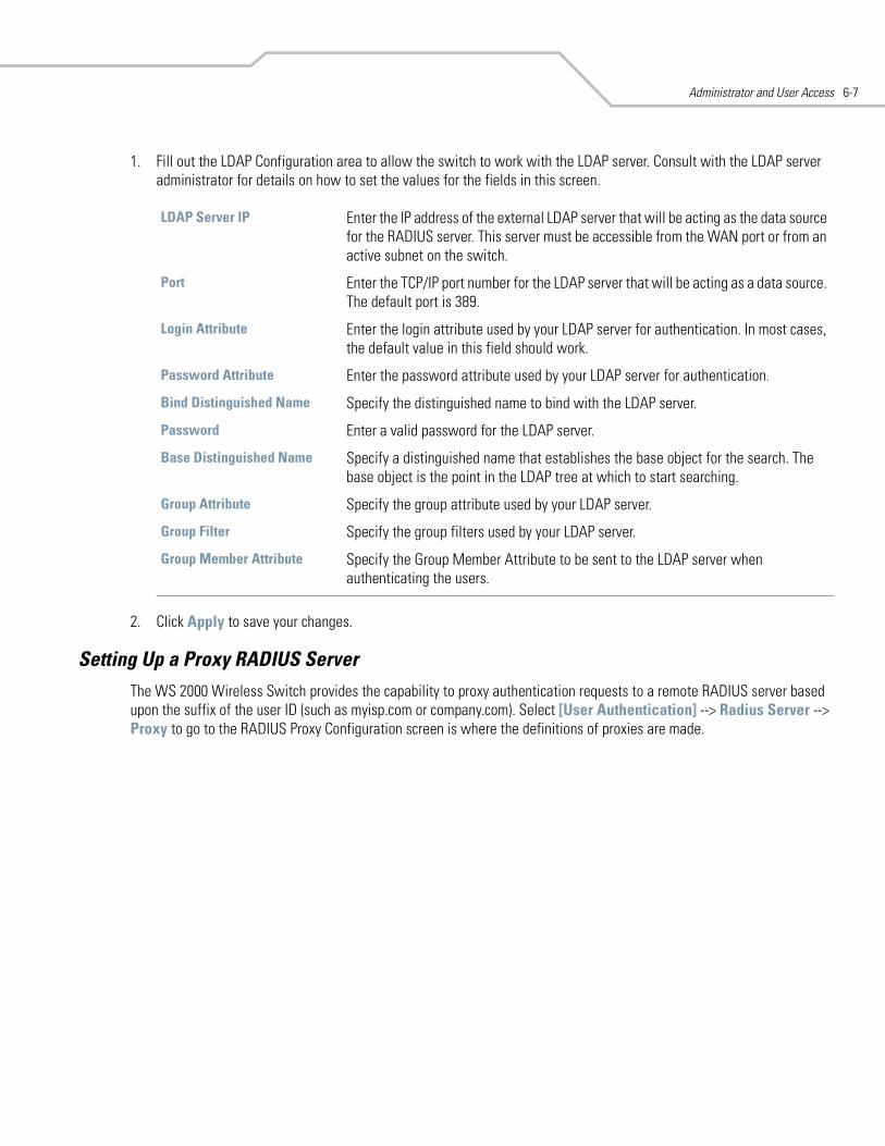
Administrator and User Access 6-7
1. Fill out the LDAP Configuration area to allow the switch to work with the LDAP server. Consult with the LDAP server administrator for details on how to set the values for the fields in this screen.
2. Click Apply to save your changes.
Setting Up a Proxy RADIUS ServerThe WS 2000 Wireless Switch provides the capability to proxy authentication requests to a remote RADIUS server based upon the suffix of the user ID (such as myisp.com or company.com). Select [User Authentication] --> Radius Server --> Proxy to go to the RADIUS Proxy Configuration screen is where the definitions of proxies are made.
LDAP Server IP Enter the IP address of the external LDAP server that will be acting as the data source for the RADIUS server. This server must be accessible from the WAN port or from an active subnet on the switch.
Port Enter the TCP/IP port number for the LDAP server that will be acting as a data source. The default port is 389.
Login Attribute Enter the login attribute used by your LDAP server for authentication. In most cases, the default value in this field should work.
Password Attribute Enter the password attribute used by your LDAP server for authentication.
Bind Distinguished Name Specify the distinguished name to bind with the LDAP server.
Password Enter a valid password for the LDAP server.
Base Distinguished Name Specify a distinguished name that establishes the base object for the search. The base object is the point in the LDAP tree at which to start searching.
Group Attribute Specify the group attribute used by your LDAP server.
Group Filter Specify the group filters used by your LDAP server.
Group Member Attribute Specify the Group Member Attribute to be sent to the LDAP server when authenticating the users.
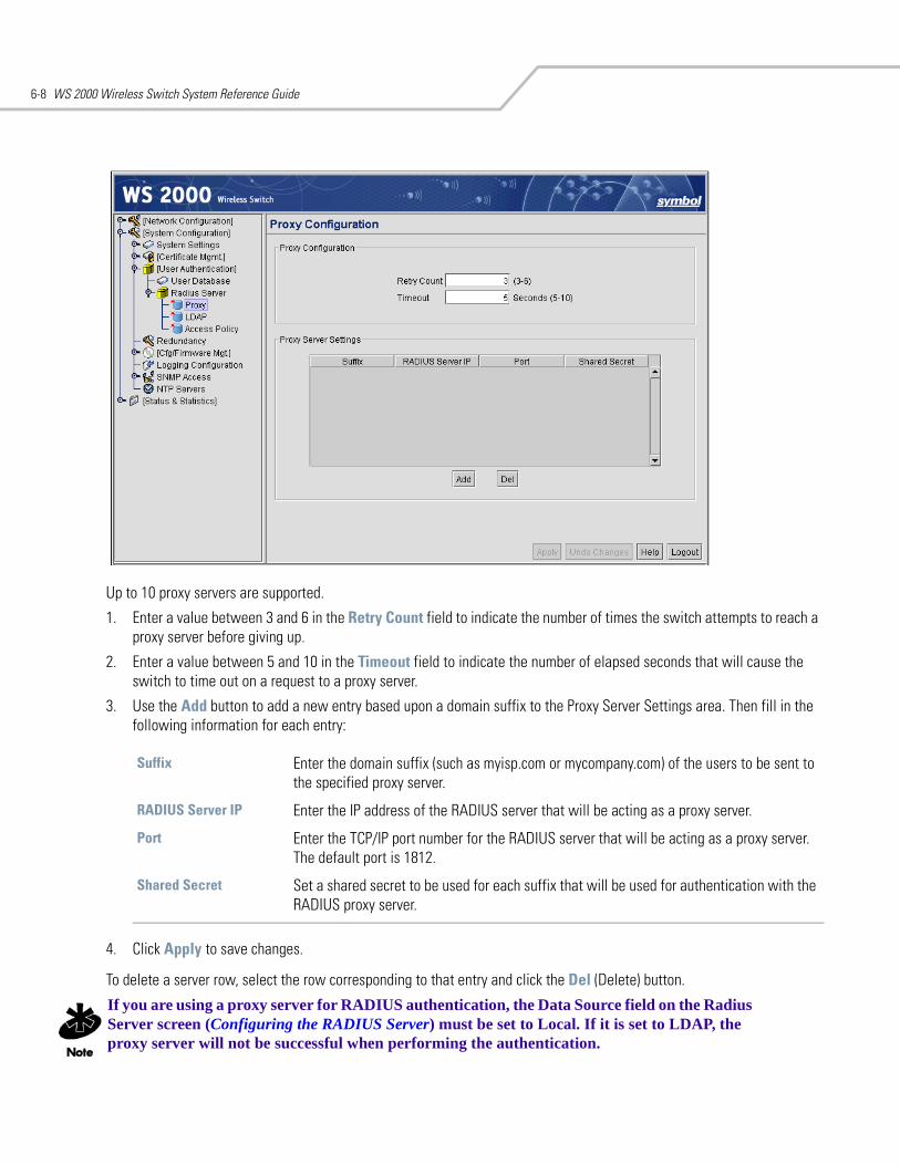
WS 2000 Wireless Switch System Reference Guide6-8
Up to 10 proxy servers are supported.
1. Enter a value between 3 and 6 in the Retry Count field to indicate the number of times the switch attempts to reach a proxy server before giving up.
2. Enter a value between 5 and 10 in the Timeout field to indicate the number of elapsed seconds that will cause the switch to time out on a request to a proxy server.
3. Use the Add button to add a new entry based upon a domain suffix to the Proxy Server Settings area. Then fill in the following information for each entry:
4. Click Apply to save changes.
To delete a server row, select the row corresponding to that entry and click the Del (Delete) button.
If you are using a proxy server for RADIUS authentication, the Data Source field on the Radius Server screen (Configuring the RADIUS Server) must be set to Local. If it is set to LDAP, the proxy server will not be successful when performing the authentication.
Suffix Enter the domain suffix (such as myisp.com or mycompany.com) of the users to be sent to the specified proxy server.
RADIUS Server IP Enter the IP address of the RADIUS server that will be acting as a proxy server.
Port Enter the TCP/IP port number for the RADIUS server that will be acting as a proxy server. The default port is 1812.
Shared Secret Set a shared secret to be used for each suffix that will be used for authentication with the RADIUS proxy server.
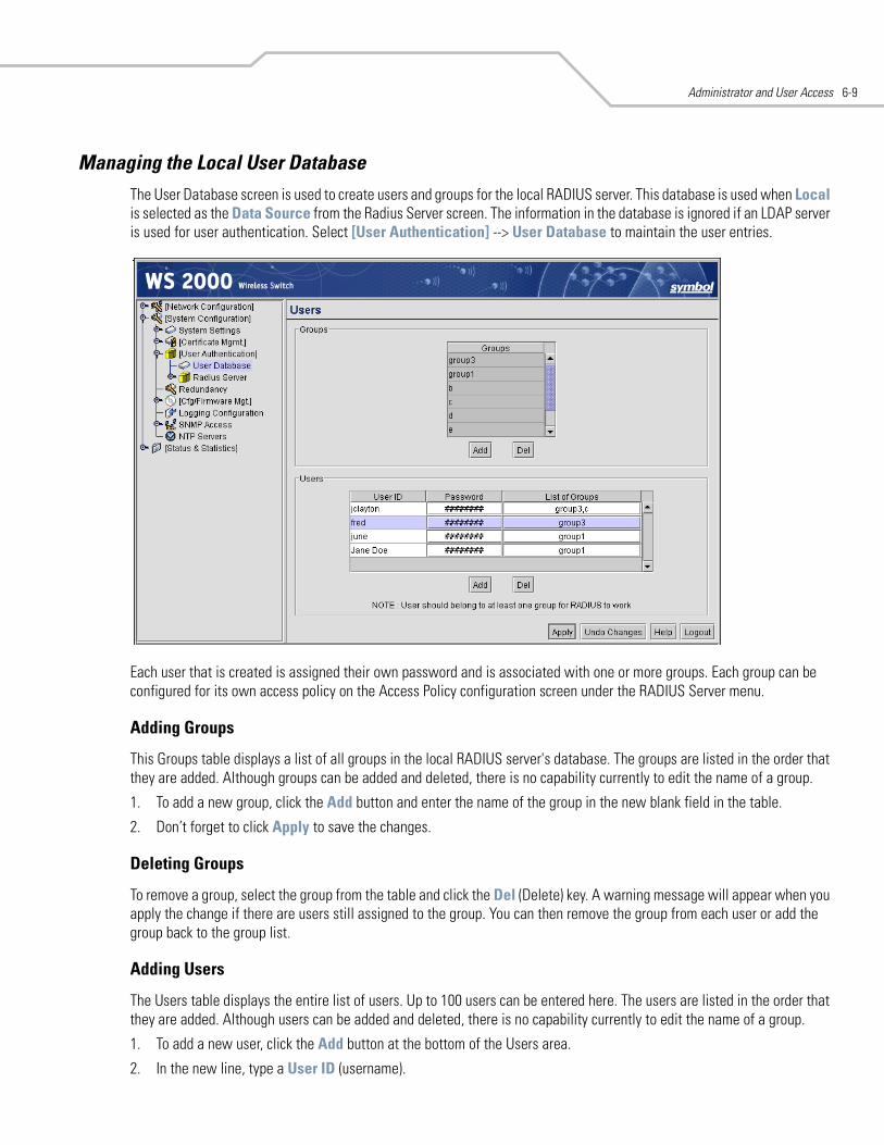
Administrator and User Access 6-9
Managing the Local User DatabaseThe User Database screen is used to create users and groups for the local RADIUS server. This database is used when Local is selected as the Data Source from the Radius Server screen. The information in the database is ignored if an LDAP server is used for user authentication. Select [User Authentication] --> User Database to maintain the user entries.
Each user that is created is assigned their own password and is associated with one or more groups. Each group can be configured for its own access policy on the Access Policy configuration screen under the RADIUS Server menu.
Adding Groups
This Groups table displays a list of all groups in the local RADIUS server's database. The groups are listed in the order that they are added. Although groups can be added and deleted, there is no capability currently to edit the name of a group.
1. To add a new group, click the Add button and enter the name of the group in the new blank field in the table.
2. Don’t forget to click Apply to save the changes.
Deleting Groups
To remove a group, select the group from the table and click the Del (Delete) key. A warning message will appear when you apply the change if there are users still assigned to the group. You can then remove the group from each user or add the group back to the group list.
Adding Users
The Users table displays the entire list of users. Up to 100 users can be entered here. The users are listed in the order that they are added. Although users can be added and deleted, there is no capability currently to edit the name of a group.
1. To add a new user, click the Add button at the bottom of the Users area.
2. In the new line, type a User ID (username).
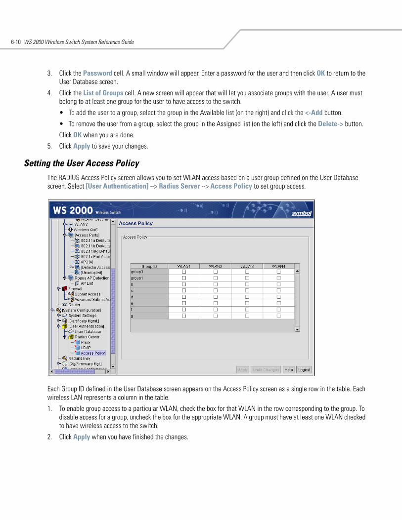
WS 2000 Wireless Switch System Reference Guide6-10
3. Click the Password cell. A small window will appear. Enter a password for the user and then click OK to return to the User Database screen.
4. Click the List of Groups cell. A new screen will appear that will let you associate groups with the user. A user must belong to at least one group for the user to have access to the switch.
• To add the user to a group, select the group in the Available list (on the right) and click the <-Add button.
• To remove the user from a group, select the group in the Assigned list (on the left) and click the Delete-> button.
Click OK when you are done.
5. Click Apply to save your changes.
Setting the User Access PolicyThe RADIUS Access Policy screen allows you to set WLAN access based on a user group defined on the User Database screen. Select [User Authentication] --> Radius Server --> Access Policy to set group access.
Each Group ID defined in the User Database screen appears on the Access Policy screen as a single row in the table. Each wireless LAN represents a column in the table.
1. To enable group access to a particular WLAN, check the box for that WLAN in the row corresponding to the group. To disable access for a group, uncheck the box for the appropriate WLAN. A group must have at least one WLAN checked to have wireless access to the switch.
2. Click Apply when you have finished the changes.
Administrator and User Access 6-11
Managing Digital CertificatesA digital certificate is an electronic identification card that establishes your credentials when doing business or other transactions on the Web. It is issued by a certification authority (CA). It contains a name, a serial number, expiration dates, a copy of the certificate holder's public key (used for encrypting messages and digital signatures), and the digital signature of the certificate-issuing authority so that a recipient can verify that the certificate is real.
The WS 2000 Wireless Switch uses digital certificates for VPN access authentication and user authentication. The application provides two mechanisms for defining/importing digital certificates:
• CA certificates are those that a CA creates and signs with its own private key. These certificates are imported into the switch CA certificate library. (See Importing CA Certificates for directions.)
• Self certificates are those that an organization creates a certificate request, sends it off to a Certificate Authority (CA) to be signed, and then imports the signed certificate into the management system. (See Creating Self Certificates for directions.)
Importing CA CertificatesA certificate authority (CA) is a network authority that issues and manages security credentials and public keys for message encryption. The CA signs all digital certificates that it issues with its own private key. The corresponding public key is contained within the certificate and is called a CA certificate. A browser must contain this CA certificate in its “Trusted Root Library” so that it can trust certificates “signed” by the CA’s private key.
Depending on the public key infrastructure implementation, the digital certificate includes the owner’s public key, the expiration date of the certificate, the owner’s name, and other information about the public key owner.
The WS 2000 Management System provides the means to import and maintain a set of CA certificates to be used as an authentication option for VPN access. To use the certificate for a VPN tunnel, define a tunnel and select the IKE settings to use either RSA or DES certificates.
Before you import a certificate, you need to get one. Ask a CA for a certificate. They will typically send you the certificate information in an email message. You will need to import the content of the message into the WS 2000 Network Management System.
Note: Make sure that the WS 2000 is time synchronized with an NTP server before importing a certificate to avoid issues with conflicting date/time stamps.
To import a CA certificate perform the following steps:
1. Select Network --> Certificates --> CA Certificates from the left menu. The following screen appears.
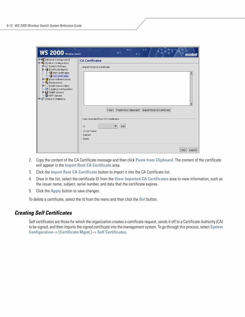
WS 2000 Wireless Switch System Reference Guide6-12
2. Copy the content of the CA Certificate message and then click Paste from Clipboard. The content of the certificate will appear in the Import Root CA Certificate area.
3. Click the Import Root CA Certificate button to import it into the CA Certificate list.
4. Once in the list, select the certificate ID from the View Imported CA Certificates area to view information, such as the issuer name, subject, serial number, and data that the certificate expires.
5. Click the Apply button to save changes.
To delete a certificate, select the Id from the menu and then click the Del button.
Creating Self CertificatesSelf certificates are those for which the organization creates a certificate request, sends it off to a Certificate Authority (CA) to be signed, and then imports the signed certificate into the management system. To go through this process, select System Configuration--> [Certificate Mgmt.]--> Self Certificates.
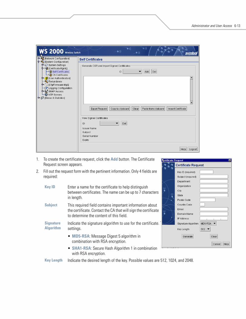
Administrator and User Access 6-13
1. To create the certificate request, click the Add button. The Certificate Request screen appears.
2. Fill out the request form with the pertinent information. Only 4 fields are required:
Key ID Enter a name for the certificate to help distinguish between certificates. The name can be up to 7 characters in length.
Subject This required field contains important information about the certificate. Contact the CA that will sign the certificate to determine the content of this field.
Signature Algorithm
Indicate the signature algorithm to use for the certificate. The selection should match the VPN tunnel settings.
• MD5-RSA: Message Digest 5 algorithm in combination with RSA encryption.
• SHA1-RSA: Secure Hash Algorithm 1 in combination with RSA encryption.
Key Length Indicate the desired length of the key. Possible values are 512, 1024, and 2048.
WS 2000 Wireless Switch System Reference Guide6-14
3. Fill in as many of the optional fields as desired or as required by the CA that will sign the certificate. The contact information is for the organization who is making the certificate request. The less obvious fields are:
4. When finished filling out the form, click Generate. The Certificate Request screen will disappear and the ID of the certificate request that was just generated will appear in the Requests ID list of the Self Certificates window.
5. Click the Export Request button. The generated certificate request appears in the large text box.
6. Click Copy to Clipboard and the content of request to be sent to the CA will be copied to the clipboard.
7. Create an email to your CA, paste the content into the body of the message, and send it off to the CA.
8. The CA will “sign” the certificate and send it back. At this point, copy the content from the email onto the clipboard. Then, click the Paste from Clipboard button and the content of the email will be displayed in the window.
9. Click the Import Certificate button to import the certificate and make it available for use as a VPN authentication option. The certificate ID will appear in the Signed list, where you can view information about it.
10. Apply your changes.
To use the certificate for a VPN tunnel, first define a tunnel and select the IKE settings to use either RSA or DES certificates.
Note: If the switch is rebooted after a certificate request has been generated but before the signed certificate is imported, the import will not execute properly. Please do not reboot the switch during this interval.
Email Enter the email address to be used for identification purposes. Typically a CA requires either an email address, a domain name, or an IP address for identification purposes.
Domain Name Enter the domain name to associate with the certificate. This field is often required by the CA.
IP Address Enter the WAN IP of the WS 2000 Wireless Switch. Check with your CA to determine whether this information is necessary. Often it can be omitted if either the email or domain name information is provided.
7Switch Administration
Overview of Administration Support . . . . . . . . . . . . . . . . . . . . . . . . . . . . . . . . . . . . . . . . . . . . . . . . . . . . . . . . . . 7-3Restarting the WS 2000 Wireless Switch . . . . . . . . . . . . . . . . . . . . . . . . . . . . . . . . . . . . . . . . . . . . . . . . . . . . . . 7-3Changing the Name of the Switch. . . . . . . . . . . . . . . . . . . . . . . . . . . . . . . . . . . . . . . . . . . . . . . . . . . . . . . . . . . . 7-4Changing the Location and Country Settings of the WS 2000 . . . . . . . . . . . . . . . . . . . . . . . . . . . . . . . . . . . . . . 7-4Configuring Switch Redundancy . . . . . . . . . . . . . . . . . . . . . . . . . . . . . . . . . . . . . . . . . . . . . . . . . . . . . . . . . . . . . 7-6
Setting Up Switch Redundancy . . . . . . . . . . . . . . . . . . . . . . . . . . . . . . . . . . . . . . . . . . . . . . . . . . . . . . . . . . 7-6Redundancy Operations Status . . . . . . . . . . . . . . . . . . . . . . . . . . . . . . . . . . . . . . . . . . . . . . . . . . . . . . . . . . 7-7
Updating the WS 2000 Wireless Switch’s Firmware . . . . . . . . . . . . . . . . . . . . . . . . . . . . . . . . . . . . . . . . . . . . . 7-7Checking for and Downloading Firmware Updates . . . . . . . . . . . . . . . . . . . . . . . . . . . . . . . . . . . . . . . . . . . 7-7Performing the Firmware Update. . . . . . . . . . . . . . . . . . . . . . . . . . . . . . . . . . . . . . . . . . . . . . . . . . . . . . . . . 7-8Setting Up DHCL Options for Firmware Upload. . . . . . . . . . . . . . . . . . . . . . . . . . . . . . . . . . . . . . . . . . . . . . 7-8
Exporting and Importing Wireless Switch Settings. . . . . . . . . . . . . . . . . . . . . . . . . . . . . . . . . . . . . . . . . . . . . . . 7-9To Import or Export Settings to an FTP or TFTP Site . . . . . . . . . . . . . . . . . . . . . . . . . . . . . . . . . . . . . . . . . 7-10To Import Settings to a Local File . . . . . . . . . . . . . . . . . . . . . . . . . . . . . . . . . . . . . . . . . . . . . . . . . . . . . . . 7-11To Export Settings to a Local File . . . . . . . . . . . . . . . . . . . . . . . . . . . . . . . . . . . . . . . . . . . . . . . . . . . . . . . 7-11Sample Configuration File . . . . . . . . . . . . . . . . . . . . . . . . . . . . . . . . . . . . . . . . . . . . . . . . . . . . . . . . . . . . . 7-11
Configuring SNMP . . . . . . . . . . . . . . . . . . . . . . . . . . . . . . . . . . . . . . . . . . . . . . . . . . . . . . . . . . . . . . . . . . . . . . . 7-19Setting the SNMP Version Configuration . . . . . . . . . . . . . . . . . . . . . . . . . . . . . . . . . . . . . . . . . . . . . . . . . 7-20Setting Up the Access Control List . . . . . . . . . . . . . . . . . . . . . . . . . . . . . . . . . . . . . . . . . . . . . . . . . . . . . . 7-21Setting the Trap Configuration . . . . . . . . . . . . . . . . . . . . . . . . . . . . . . . . . . . . . . . . . . . . . . . . . . . . . . . . . 7-22Setting the Trap Configuration for SNMP v1/v2c . . . . . . . . . . . . . . . . . . . . . . . . . . . . . . . . . . . . . . . . . . . 7-22Setting the Trap Configuration for SNMP V3 . . . . . . . . . . . . . . . . . . . . . . . . . . . . . . . . . . . . . . . . . . . . . . 7-23Selecting Traps. . . . . . . . . . . . . . . . . . . . . . . . . . . . . . . . . . . . . . . . . . . . . . . . . . . . . . . . . . . . . . . . . . . . . . 7-23Setting Rate Traps . . . . . . . . . . . . . . . . . . . . . . . . . . . . . . . . . . . . . . . . . . . . . . . . . . . . . . . . . . . . . . . . . . . 7-26
Specifying a Network Time Protocol (NTP) Server . . . . . . . . . . . . . . . . . . . . . . . . . . . . . . . . . . . . . . . . . . . . . . 7-27

WS 2000 Wireless Switch System Reference Guide7-2
Setting Up and Viewing the System Log . . . . . . . . . . . . . . . . . . . . . . . . . . . . . . . . . . . . . . . . . . . . . . . . . . . . . .7-28Viewing the Log on the Switch . . . . . . . . . . . . . . . . . . . . . . . . . . . . . . . . . . . . . . . . . . . . . . . . . . . . . . . . .7-28Setting Up a Log Server . . . . . . . . . . . . . . . . . . . . . . . . . . . . . . . . . . . . . . . . . . . . . . . . . . . . . . . . . . . . . . .7-29
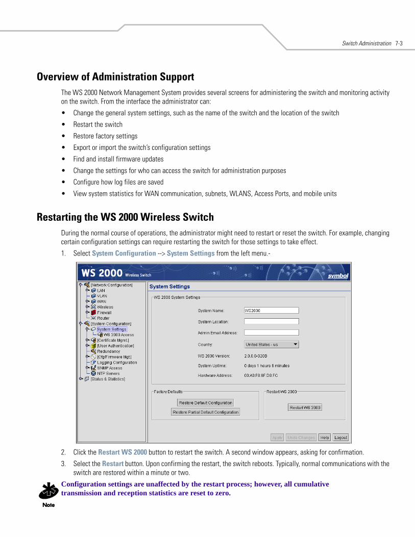
Switch Administration 7-3
Overview of Administration SupportThe WS 2000 Network Management System provides several screens for administering the switch and monitoring activity on the switch. From the interface the administrator can:
• Change the general system settings, such as the name of the switch and the location of the switch
• Restart the switch
• Restore factory settings
• Export or import the switch’s configuration settings
• Find and install firmware updates
• Change the settings for who can access the switch for administration purposes
• Configure how log files are saved
• View system statistics for WAN communication, subnets, WLANS, Access Ports, and mobile units
Restarting the WS 2000 Wireless SwitchDuring the normal course of operations, the administrator might need to restart or reset the switch. For example, changing certain configuration settings can require restarting the switch for those settings to take effect.
1. Select System Configuration --> System Settings from the left menu.-
2. Click the Restart WS 2000 button to restart the switch. A second window appears, asking for confirmation.
3. Select the Restart button. Upon confirming the restart, the switch reboots. Typically, normal communications with the switch are restored within a minute or two.
Configuration settings are unaffected by the restart process; however, all cumulative transmission and reception statistics are reset to zero.
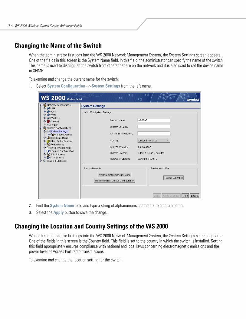
WS 2000 Wireless Switch System Reference Guide7-4
Changing the Name of the SwitchWhen the administrator first logs into the WS 2000 Network Management System, the System Settings screen appears. One of the fields in this screen is the System Name field. In this field, the administrator can specify the name of the switch. This name is used to distinguish the switch from others that are on the network and it is also used to set the device name in SNMP.
To examine and change the current name for the switch:
1. Select System Configuration --> System Settings from the left menu.
2. Find the System Name field and type a string of alphanumeric characters to create a name.
3. Select the Apply button to save the change.
Changing the Location and Country Settings of the WS 2000When the administrator first logs into the WS 2000 Network Management System, the System Settings screen appears. One of the fields in this screen is the Country field. This field is set to the country in which the switch is installed. Setting this field appropriately ensures compliance with national and local laws concerning electromagnetic emissions and the power level of Access Port radio transmissions.
To examine and change the location setting for the switch:
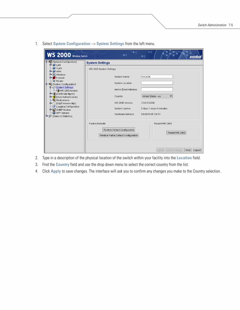
Switch Administration 7-5
1. Select System Configuration --> System Settings from the left menu.
2. Type in a description of the physical location of the switch within your facility into the Location field.
3. Find the Country field and use the drop down menu to select the correct country from the list.
4. Click Apply to save changes. The interface will ask you to confirm any changes you make to the Country selection.

WS 2000 Wireless Switch System Reference Guide7-6
Configuring Switch RedundancyThe WS 2000 Wireless Switch supports redundancy between two WS 2000 Wireless Switches, allowing a standby switch to take over if the primary switch stop responding. Use the WS 2000 Redundancy Settings to configure the Operational State and Redundancy Mode for the switch.
Setting Up Switch RedundancyFor each of the two switches, use the following procedure to set up redundancy.
1. Choose the redundancy mode in which the WS 2000 Wireless Switch will operate in.
2. When operating in redundancy mode, the primary and standby switches must be connected by an Ethernet cable through a hub. From the Heartbeat Port menu, select the physical port that is used to exchange heartbeat packets between the two switches.
3. When redundancy is selected as the operational state, specify whether the current switch is the primary or standby switch by selecting the appropriate Redundancy mode radio button.
Stand-alone The switch has no redundancy capabilities and operates independently of any other WS 2000 switches on the network. This is the default setting.
Upgrade The primary and standby switches must run the same version of the switch firmware for redundancy to work correctly. If the firmware on only one of the switches is updated, redundancy is disabled and the Operational State is automatically set to Upgrade.
Redundancy Two WS 2000 switches are connected, with one set as a primary and the other as a standby. The primary switch will send heartbeat packets to the specified port of the standby switch at a specified interval. If the standby switch doesn't receive a heartbeat packet in a specified amount of time, it will take over as the primary switch.
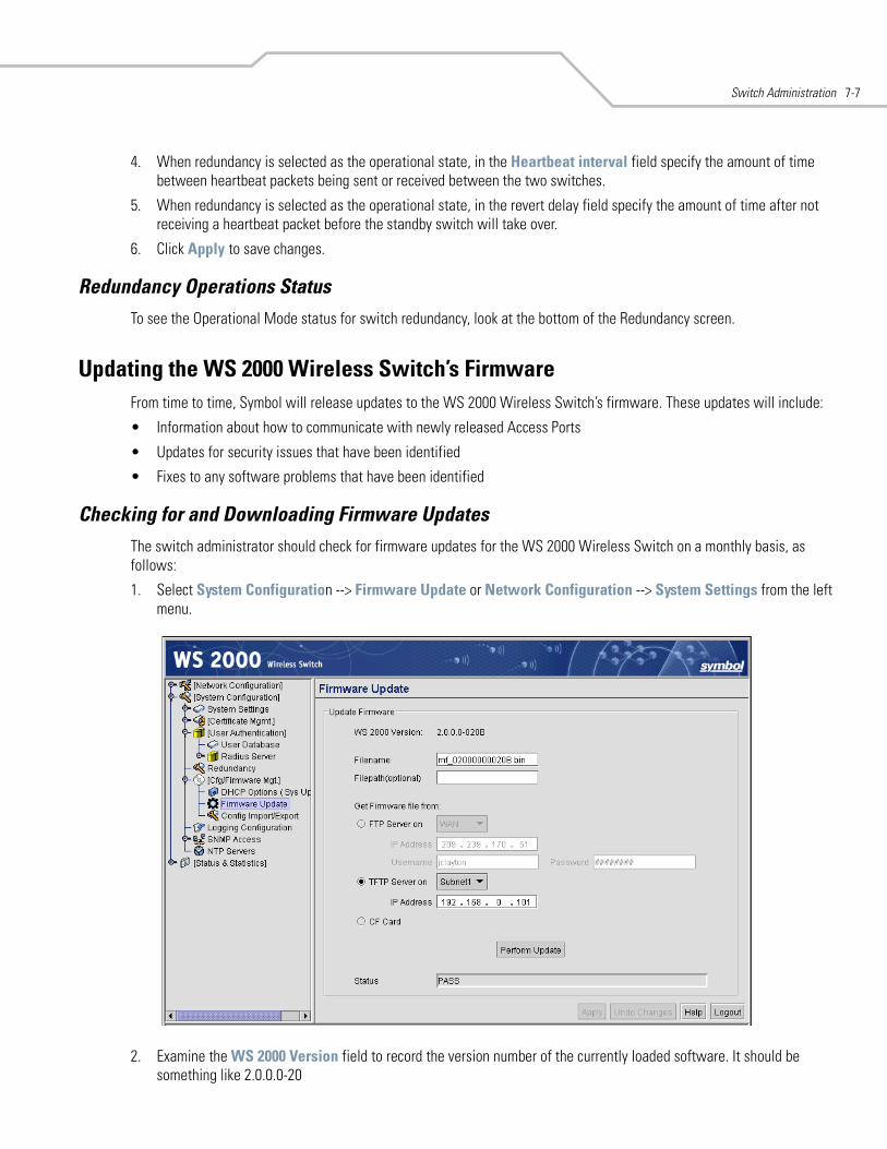
Switch Administration 7-7
4. When redundancy is selected as the operational state, in the Heartbeat interval field specify the amount of time between heartbeat packets being sent or received between the two switches.
5. When redundancy is selected as the operational state, in the revert delay field specify the amount of time after not receiving a heartbeat packet before the standby switch will take over.
6. Click Apply to save changes.
Redundancy Operations StatusTo see the Operational Mode status for switch redundancy, look at the bottom of the Redundancy screen.
Updating the WS 2000 Wireless Switch’s FirmwareFrom time to time, Symbol will release updates to the WS 2000 Wireless Switch’s firmware. These updates will include:
• Information about how to communicate with newly released Access Ports
• Updates for security issues that have been identified
• Fixes to any software problems that have been identified
Checking for and Downloading Firmware UpdatesThe switch administrator should check for firmware updates for the WS 2000 Wireless Switch on a monthly basis, as follows:
1. Select System Configuration --> Firmware Update or Network Configuration --> System Settings from the left menu.
2. Examine the WS 2000 Version field to record the version number of the currently loaded software. It should be something like 2.0.0.0-20
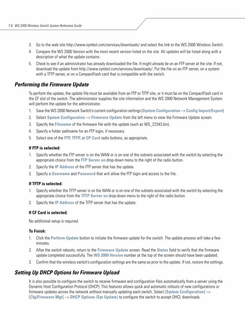
WS 2000 Wireless Switch System Reference Guide7-8
3. Go to the web site http://www.symbol.com/services/downloads/ and select the link to the WS 2000 Wireless Switch.
4. Compare the WS 2000 Version with the most recent version listed on the site. All updates will be listed along with a description of what the update contains.
5. Check to see if an administrator has already downloaded the file. It might already be on an FTP server at the site. If not, download the update from http://www.symbol.com/services/downloads/. Put the file on an FTP server, on a system with a TFTP server, or on a CompactFlash card that is compatible with the switch.
Performing the Firmware UpdateTo perform the update, the update file must be available from an FTP or TFTP site, or it must be on the CompactFlash card in the CF slot of the switch. The administrator supplies the site information and the WS 2000 Network Management System will perform the update for the administrator.
1. Save the WS 2000 Network Switch’s current configuration settings (System Configuration --> Config Import/Export)
2. Select System Configuration --> Firmware Update from the left menu to view the Firmware Update screen.
3. Specify the Filename of the firmware file with the update (such as WS_22343.bin).
4. Specify a folder pathname for an FTP login, if necessary.
5. Select one of the FTP, TFTP, or CP Card radio buttons, as appropriate.
If FTP is selected:
1. Specify whether the FTP server is on the WAN or is on one of the subnets associated with the switch by selecting the appropriate choice from the FTP Server on drop-down menu to the right of the radio button.
2. Specify the IP Address of the FTP server that has the update.
3. Specify a Username and Password that will allow the FTP login and access to the file.
If TFTP is selected:
1. Specify whether the TFTP server is on the WAN or is on one of the subnets associated with the switch by selecting the appropriate choice from the TFTP Server on drop-down menu to the right of the radio button.
2. Specify the IP Address of the TFTP server that has the update.
If CF Card is selected:
No additional setup is required.
To Finish:
1. Click the Perform Update button to initiate the firmware update for the switch. The update process will take a few minutes.
2. After the switch reboots, return to the Firmware Update screen. Read the Status field to verify that the firmware update completed successfully. The WS 2000 Version number at the top of the screen should have been updated.
3. Confirm that the wireless switch’s configuration settings are the same as prior to the update. If not, restore the settings.
Setting Up DHCP Options for Firmware UploadIt is also possible to configure the switch to receive firmware and configuration files automatically from a server using the Dynamic Host Configuration Protocol (DHCP). This features allows quick and automatic rollouts of new configurations or firmware updates across the network without manually updating each switch. Select [System Configuration] --> [Cfg/Firmware Mgt] --> DHCP Options (Sys Update) to configure the switch to accept DHCL downloads.
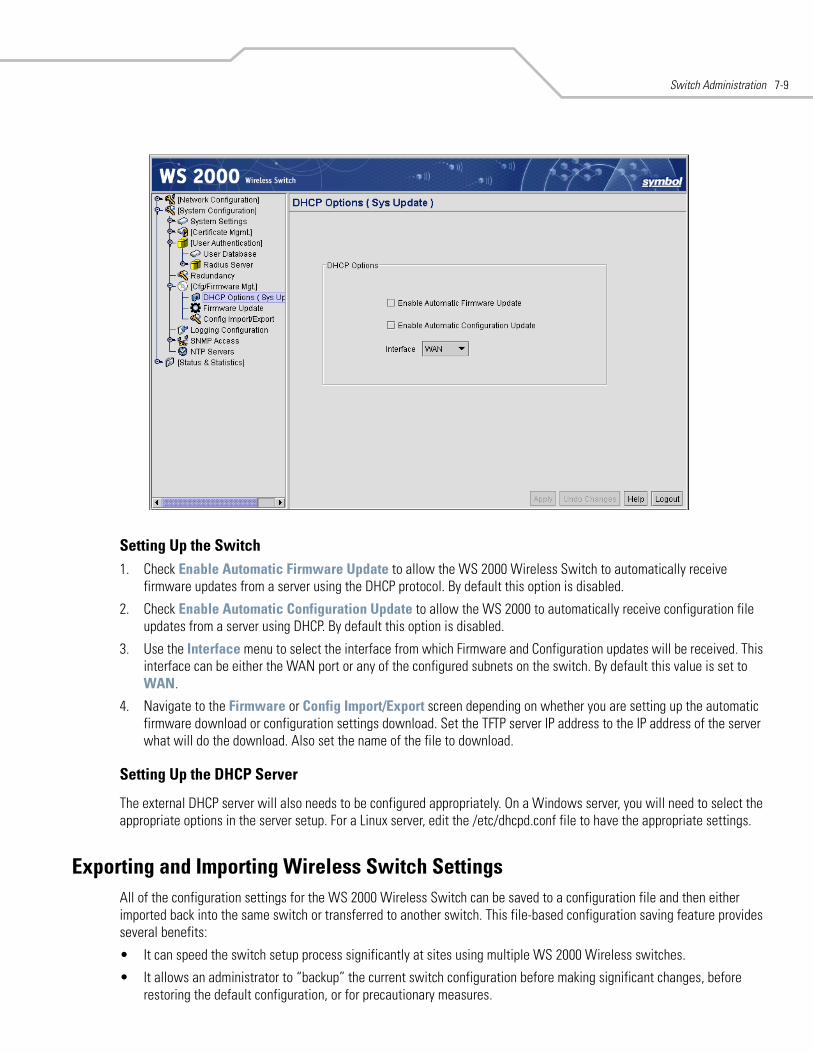
Switch Administration 7-9
Setting Up the Switch1. Check Enable Automatic Firmware Update to allow the WS 2000 Wireless Switch to automatically receive
firmware updates from a server using the DHCP protocol. By default this option is disabled.
2. Check Enable Automatic Configuration Update to allow the WS 2000 to automatically receive configuration file updates from a server using DHCP. By default this option is disabled.
3. Use the Interface menu to select the interface from which Firmware and Configuration updates will be received. This interface can be either the WAN port or any of the configured subnets on the switch. By default this value is set to WAN.
4. Navigate to the Firmware or Config Import/Export screen depending on whether you are setting up the automatic firmware download or configuration settings download. Set the TFTP server IP address to the IP address of the server what will do the download. Also set the name of the file to download.
Setting Up the DHCP Server
The external DHCP server will also needs to be configured appropriately. On a Windows server, you will need to select the appropriate options in the server setup. For a Linux server, edit the /etc/dhcpd.conf file to have the appropriate settings.
Exporting and Importing Wireless Switch Settings All of the configuration settings for the WS 2000 Wireless Switch can be saved to a configuration file and then either imported back into the same switch or transferred to another switch. This file-based configuration saving feature provides several benefits:
• It can speed the switch setup process significantly at sites using multiple WS 2000 Wireless switches.
• It allows an administrator to “backup” the current switch configuration before making significant changes, before restoring the default configuration, or for precautionary measures.
WS 2000 Wireless Switch System Reference Guide7-10
Select System Configuration --> Config Import/Export from the left menu to import or export the switch configuration settings.
To Import or Export Settings to an FTP or TFTP SiteUse the following procedure for exporting the switch’s configuration settings.
1. Specify the name of the log Filename (under Server Options) to be written to or read from the FTP server.
2. Specify the Server IP address of the FTP server to which the log file will be imported or exported.
3. Specify the Username to be used when logging in to the FTP server. The user account must be established on the FTP server that is targeted for importing or exporting file data.
4. Specify the Password that will allow the user access to the FTP server for the import or export operation.
5. Click the appropriate import or export button with the given filename and login information.
• Click the FTP Import button to import the configuration file from an FTP server.
• Click the TFTP Import button to import the configuration file from a TFTP server.
• Click the FTP Export button to export the configuration to a file on the FTP server.
• Click the TFTP Export button to export the configuration to a file on the TFTP server.
When importing configuration settings, the system will display a confirmation window indicating that you must log out of the switch after the operation completes for the changes to take effect.
6. After executing the export, check the Status field for messages about the success or errors in executing the specified operation.
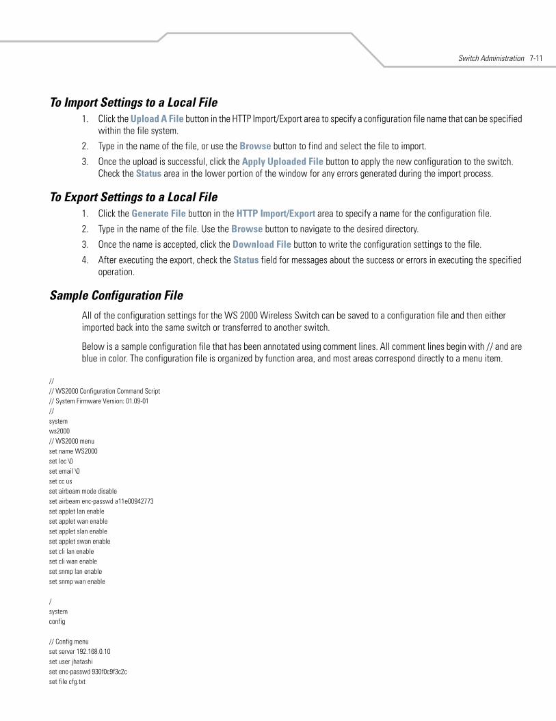
Switch Administration 7-11
To Import Settings to a Local File1. Click the Upload A File button in the HTTP Import/Export area to specify a configuration file name that can be specified
within the file system.
2. Type in the name of the file, or use the Browse button to find and select the file to import.
3. Once the upload is successful, click the Apply Uploaded File button to apply the new configuration to the switch. Check the Status area in the lower portion of the window for any errors generated during the import process.
To Export Settings to a Local File1. Click the Generate File button in the HTTP Import/Export area to specify a name for the configuration file.
2. Type in the name of the file. Use the Browse button to navigate to the desired directory.
3. Once the name is accepted, click the Download File button to write the configuration settings to the file.
4. After executing the export, check the Status field for messages about the success or errors in executing the specified operation.
Sample Configuration FileAll of the configuration settings for the WS 2000 Wireless Switch can be saved to a configuration file and then either imported back into the same switch or transferred to another switch.
Below is a sample configuration file that has been annotated using comment lines. All comment lines begin with // and are blue in color. The configuration file is organized by function area, and most areas correspond directly to a menu item.
//// WS2000 Configuration Command Script// System Firmware Version: 01.09-01 //systemws2000// WS2000 menuset name WS2000set loc \0set email \0set cc usset airbeam mode disableset airbeam enc-passwd a11e00942773set applet lan enableset applet wan enableset applet slan enableset applet swan enableset cli lan enableset cli wan enableset snmp lan enableset snmp wan enable
/systemconfig
// Config menuset server 192.168.0.10set user jhatashiset enc-passwd 930f0c9f3c2cset file cfg.txt
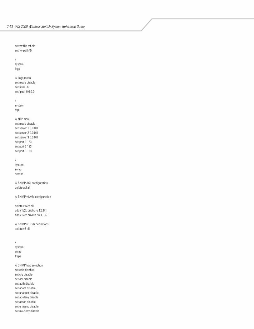
WS 2000 Wireless Switch System Reference Guide7-12
set fw file mf.binset fw path \0
/systemlogs
// Logs menuset mode disableset level L6set ipadr 0.0.0.0
/systemntp
// NTP menuset mode disableset server 1 0.0.0.0set server 2 0.0.0.0set server 3 0.0.0.0set port 1 123set port 2 123set port 3 123
/systemsnmpaccess
// SNMP ACL configurationdelete acl all
// SNMP v1/v2c configuration
delete v1v2c alladd v1v2c public ro 1.3.6.1add v1v2c private rw 1.3.6.1
// SNMP v3 user definitionsdelete v3 all
/systemsnmptraps
// SNMP trap selectionset cold disableset cfg disableset acl disableset auth disableset adopt disableset unadopt disableset ap-deny disableset assoc disableset unassoc disableset mu-deny disable
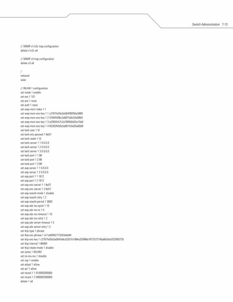
Switch Administration 7-13
// SNMP v1/v2c trap configurationdelete v1v2c all
// SNMP v3 trap configurationdelete v3 all
/networkwlan
// WLAN 1 configurationset mode 1 enableset ess 1 101set enc 1 noneset auth 1 noneset wep-mcm index 1 1set wep-mcm enc-key 1 1 c2767fe55c0a564f90f50a3989set wep-mcm enc-key 1 2 f2464fd56c3a667fa0c53a09b9set wep-mcm enc-key 1 3 e2565fc57c2a766fb0d52a19a9set wep-mcm enc-key 1 4 92262fb50c5a061fc0a55a69d9set kerb user 1 \0set kerb enc-passwd 1 8e57set kerb realm 1 \0set kerb server 1 1 0.0.0.0set kerb server 1 2 0.0.0.0set kerb server 1 3 0.0.0.0set kerb port 1 1 88set kerb port 1 2 88set kerb port 1 3 88set eap server 1 1 0.0.0.0set eap server 1 2 0.0.0.0set eap port 1 1 1812set eap port 1 2 1812set eap enc-secret 1 1 8e57set eap enc-secret 1 2 8e57set eap reauth mode 1 disableset eap reauth retry 1 2set eap reauth period 1 3600set eap adv mu-quiet 1 10set eap adv mu-tx 1 5set eap adv mu-timeout 1 10set eap adv mu-retry 1 2set eap adv server-timeout 1 5set eap adv server-retry 1 2set tkip type 1 phraseset tkip enc-phrase 1 a11e00942773343deb84set tkip enc-key 1 c2767fe55c0a564fa8cd3201b1984a33f986e7872572740a80c6dcff32905735set tkip interval 1 86400set tkip rotate-mode 1 disableset name 1 WLAN1set no-mu-mu 1 disableset vop 1 enableset adopt 1 allowset acl 1 allowset mcast 1 1 01005E000000set mcast 1 2 09000E000000delete 1 all
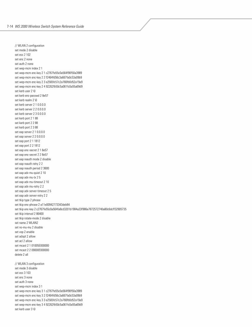
WS 2000 Wireless Switch System Reference Guide7-14
// WLAN 2 configurationset mode 2 disableset ess 2 102set enc 2 noneset auth 2 noneset wep-mcm index 2 1set wep-mcm enc-key 2 1 c2767fe55c0a564f90f50a3989set wep-mcm enc-key 2 2 f2464fd56c3a667fa0c53a09b9set wep-mcm enc-key 2 3 e2565fc57c2a766fb0d52a19a9set wep-mcm enc-key 2 4 92262fb50c5a061fc0a55a69d9set kerb user 2 \0set kerb enc-passwd 2 8e57set kerb realm 2 \0set kerb server 2 1 0.0.0.0set kerb server 2 2 0.0.0.0set kerb server 2 3 0.0.0.0set kerb port 2 1 88set kerb port 2 2 88set kerb port 2 3 88set eap server 2 1 0.0.0.0set eap server 2 2 0.0.0.0set eap port 2 1 1812set eap port 2 2 1812set eap enc-secret 2 1 8e57set eap enc-secret 2 2 8e57set eap reauth mode 2 disableset eap reauth retry 2 2set eap reauth period 2 3600set eap adv mu-quiet 2 10set eap adv mu-tx 2 5set eap adv mu-timeout 2 10set eap adv mu-retry 2 2set eap adv server-timeout 2 5set eap adv server-retry 2 2set tkip type 2 phraseset tkip enc-phrase 2 a11e00942773343deb84set tkip enc-key 2 c2767fe55c0a564fa8cd3201b1984a33f986e7872572740a80c6dcff32905735set tkip interval 2 86400set tkip rotate-mode 2 disableset name 2 WLAN2set no-mu-mu 2 disableset vop 2 enableset adopt 2 allowset acl 2 allowset mcast 2 1 01005E000000set mcast 2 2 09000E000000delete 2 all
// WLAN 3 configurationset mode 3 disableset ess 3 103set enc 3 noneset auth 3 noneset wep-mcm index 3 1set wep-mcm enc-key 3 1 c2767fe55c0a564f90f50a3989set wep-mcm enc-key 3 2 f2464fd56c3a667fa0c53a09b9set wep-mcm enc-key 3 3 e2565fc57c2a766fb0d52a19a9set wep-mcm enc-key 3 4 92262fb50c5a061fc0a55a69d9set kerb user 3 \0
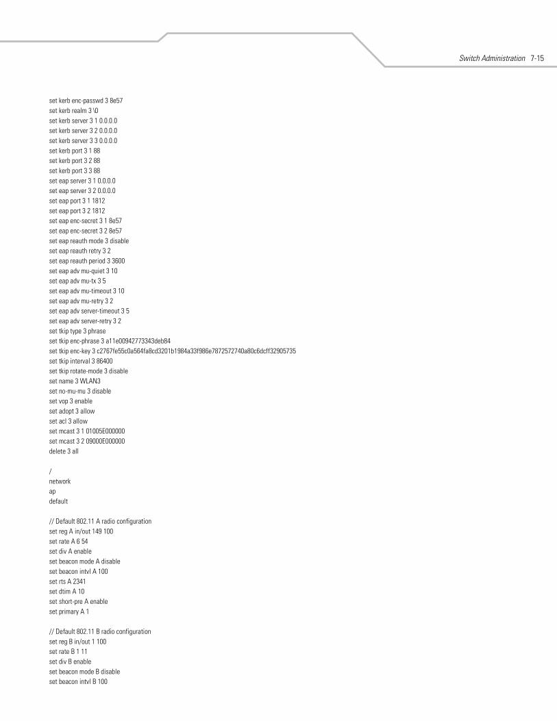
Switch Administration 7-15
set kerb enc-passwd 3 8e57set kerb realm 3 \0set kerb server 3 1 0.0.0.0set kerb server 3 2 0.0.0.0set kerb server 3 3 0.0.0.0set kerb port 3 1 88set kerb port 3 2 88set kerb port 3 3 88set eap server 3 1 0.0.0.0set eap server 3 2 0.0.0.0set eap port 3 1 1812set eap port 3 2 1812set eap enc-secret 3 1 8e57set eap enc-secret 3 2 8e57set eap reauth mode 3 disableset eap reauth retry 3 2set eap reauth period 3 3600set eap adv mu-quiet 3 10set eap adv mu-tx 3 5set eap adv mu-timeout 3 10set eap adv mu-retry 3 2set eap adv server-timeout 3 5set eap adv server-retry 3 2set tkip type 3 phraseset tkip enc-phrase 3 a11e00942773343deb84set tkip enc-key 3 c2767fe55c0a564fa8cd3201b1984a33f986e7872572740a80c6dcff32905735set tkip interval 3 86400set tkip rotate-mode 3 disableset name 3 WLAN3set no-mu-mu 3 disableset vop 3 enableset adopt 3 allowset acl 3 allowset mcast 3 1 01005E000000set mcast 3 2 09000E000000delete 3 all
/networkapdefault
// Default 802.11 A radio configurationset reg A in/out 149 100set rate A 6 54set div A enableset beacon mode A disableset beacon intvl A 100set rts A 2341set dtim A 10set short-pre A enableset primary A 1
// Default 802.11 B radio configurationset reg B in/out 1 100set rate B 1 11set div B enableset beacon mode B disableset beacon intvl B 100
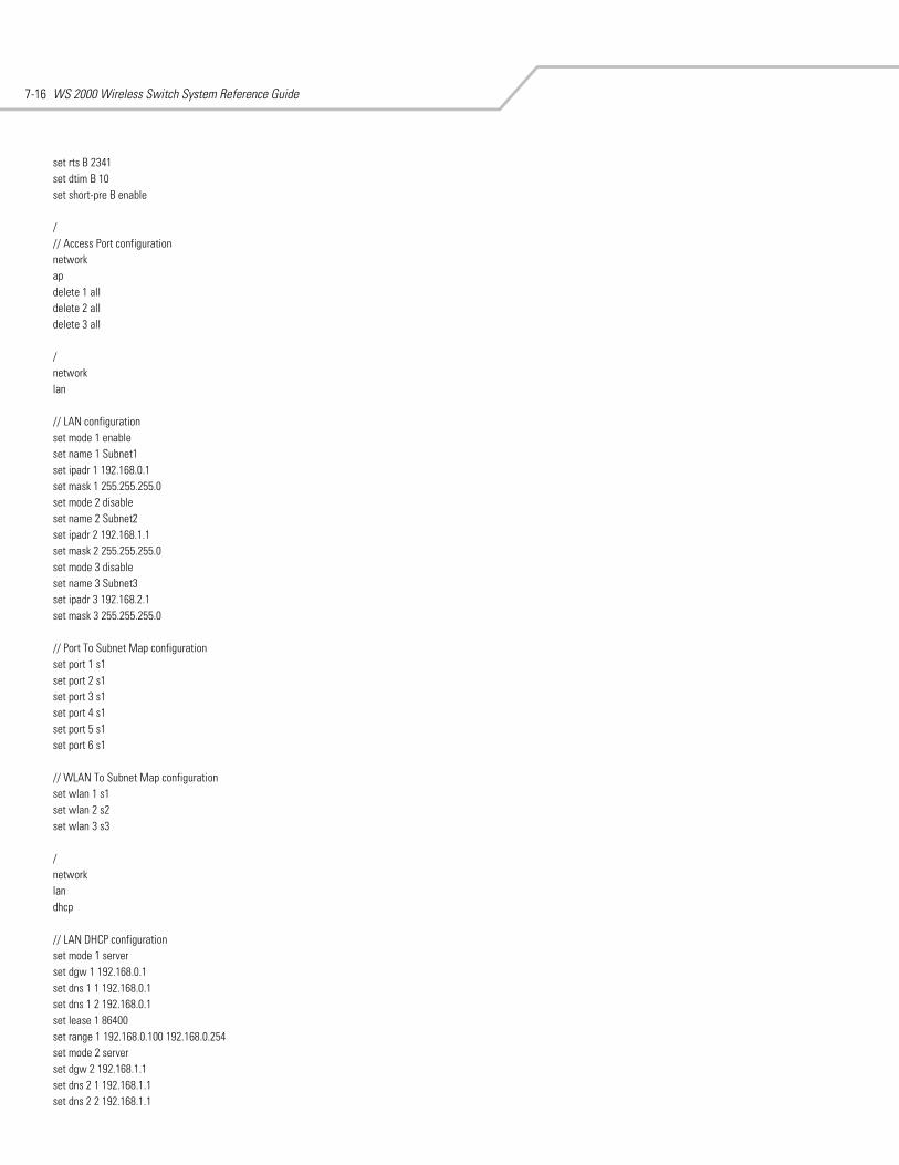
WS 2000 Wireless Switch System Reference Guide7-16
set rts B 2341set dtim B 10set short-pre B enable
/// Access Port configurationnetworkapdelete 1 alldelete 2 alldelete 3 all
/networklan
// LAN configurationset mode 1 enableset name 1 Subnet1set ipadr 1 192.168.0.1set mask 1 255.255.255.0set mode 2 disableset name 2 Subnet2set ipadr 2 192.168.1.1set mask 2 255.255.255.0set mode 3 disableset name 3 Subnet3set ipadr 3 192.168.2.1set mask 3 255.255.255.0
// Port To Subnet Map configurationset port 1 s1set port 2 s1set port 3 s1set port 4 s1set port 5 s1set port 6 s1
// WLAN To Subnet Map configurationset wlan 1 s1set wlan 2 s2set wlan 3 s3
/networklandhcp
// LAN DHCP configurationset mode 1 serverset dgw 1 192.168.0.1set dns 1 1 192.168.0.1set dns 1 2 192.168.0.1set lease 1 86400set range 1 192.168.0.100 192.168.0.254set mode 2 serverset dgw 2 192.168.1.1set dns 2 1 192.168.1.1set dns 2 2 192.168.1.1

Switch Administration 7-17
set lease 2 86400set range 2 192.168.1.100 192.168.1.254set mode 3 serverset dgw 3 192.168.2.1set dns 3 1 192.168.2.1set dns 3 2 192.168.2.1set lease 3 86400set range 3 192.168.2.100 192.168.2.254delete 1 alldelete 2 alldelete 3 all/networkwan
// WAN configurationset dhcp enable set mask 255.255.255.0set dgw 0.0.0.0set dns 1 0.0.0.0set dns 2 0.0.0.0set pppoe mode disableset pppoe user \0set pppoe enc-passwd 8e57set pppoe idle 600set pppoe ka disableset pppoe type pap/chapset mode 1 enableset ipadr 1 0.0.0.0set mode 2 disableset ipadr 2 0.0.0.0set mode 3 disableset ipadr 3 0.0.0.0set mode 4 disableset ipadr 4 0.0.0.0set mode 5 disableset ipadr 5 0.0.0.0set mode 6 disableset ipadr 6 0.0.0.0set mode 7 disableset ipadr 7 0.0.0.0set mode 8 disableset ipadr 8 0.0.0.0
/networkwanfw
// Firewall configurationset syn enableset src enableset win enableset ftp enableset ip enableset seq enableset mime filter enableset mime len 8192set mime hdr 16
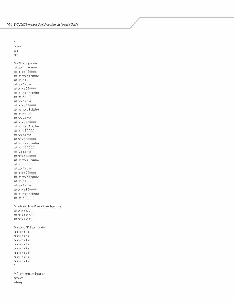
WS 2000 Wireless Switch System Reference Guide7-18
/networkwannat
// NAT configurationset type 1 1-to-manyset outb ip 1 0.0.0.0set inb mode 1 disableset inb ip 1 0.0.0.0set type 2 noneset outb ip 2 0.0.0.0set inb mode 2 disableset inb ip 2 0.0.0.0set type 3 noneset outb ip 3 0.0.0.0set inb mode 3 disableset inb ip 3 0.0.0.0set type 4 noneset outb ip 4 0.0.0.0set inb mode 4 disableset inb ip 4 0.0.0.0set type 5 noneset outb ip 5 0.0.0.0set inb mode 5 disableset inb ip 5 0.0.0.0set type 6 noneset outb ip 6 0.0.0.0set inb mode 6 disableset inb ip 6 0.0.0.0set type 7 noneset outb ip 7 0.0.0.0set inb mode 7 disableset inb ip 7 0.0.0.0set type 8 noneset outb ip 8 0.0.0.0set inb mode 8 disableset inb ip 8 0.0.0.0
// Outbound 1-To-Many NAT configurationset outb map s1 1set outb map s2 1set outb map s3 1
// Inbound NAT configurationdelete inb 1 alldelete inb 2 alldelete inb 3 alldelete inb 4 alldelete inb 5 alldelete inb 6 alldelete inb 7 alldelete inb 8 all/
// Subnet map configurationnetworksubmap
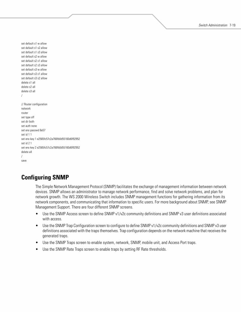
Switch Administration 7-19
set default s1 w allowset default s1 s2 allowset default s1 s3 allowset default s2 w allowset default s2 s1 allowset default s2 s3 allowset default s3 w allowset default s3 s1 allowset default s3 s2 allowdelete s1 alldelete s2 alldelete s3 all/
// Router configurationnetworkrouterset type offset dir bothset auth noneset enc-passwd 8e57set id 1 1set enc-key 1 e2565fc57c2a766fb0d55160d6f92952set id 2 1set enc-key 2 e2565fc57c2a766fb0d55160d6f92952delete all/save
Configuring SNMPThe Simple Network Management Protocol (SNMP) facilitates the exchange of management information between network devices. SNMP allows an administrator to manage network performance, find and solve network problems, and plan for network growth. The WS 2000 Wireless Switch includes SNMP management functions for gathering information from its network components, and communicating that information to specific users. For more background about SNMP, see SNMP Management Support. There are four different SNMP screens.
• Use the SNMP Access screen to define SNMP v1/v2c community definitions and SNMP v3 user definitions associated with access.
• Use the SNMP Trap Configuration screen to configure to define SNMP v1/v2c community definitions and SNMP v3 user definitions associated with the traps themselves. Trap configuration depends on the network machine that receives the generated traps.
• Use the SNMP Traps screen to enable system, network, SNMP, mobile unit, and Access Port traps.
• Use the SNMP Rate Traps screen to enable traps by setting RF Rate thresholds.
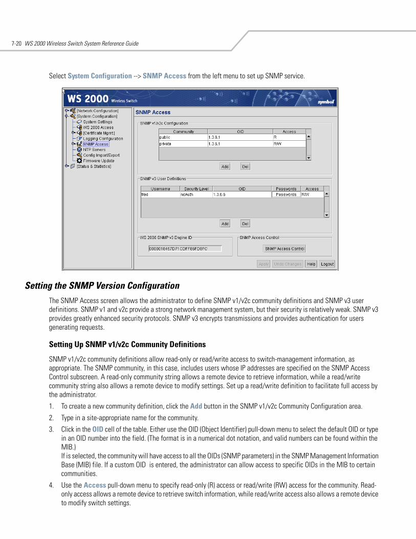
WS 2000 Wireless Switch System Reference Guide7-20
Select System Configuration --> SNMP Access from the left menu to set up SNMP service.
Setting the SNMP Version ConfigurationThe SNMP Access screen allows the administrator to define SNMP v1/v2c community definitions and SNMP v3 user definitions. SNMP v1 and v2c provide a strong network management system, but their security is relatively weak. SNMP v3 provides greatly enhanced security protocols. SNMP v3 encrypts transmissions and provides authentication for users generating requests.
Setting Up SNMP v1/v2c Community Definitions
SNMP v1/v2c community definitions allow read-only or read/write access to switch-management information, as appropriate. The SNMP community, in this case, includes users whose IP addresses are specified on the SNMP Access Control subscreen. A read-only community string allows a remote device to retrieve information, while a read/write community string also allows a remote device to modify settings. Set up a read/write definition to facilitate full access by the administrator.
1. To create a new community definition, click the Add button in the SNMP v1/v2c Community Configuration area.
2. Type in a site-appropriate name for the community.
3. Click in the OID cell of the table. Either use the OID (Object Identifier) pull-down menu to select the default OID or type in an OID number into the field. (The format is in a numerical dot notation, and valid numbers can be found within the MIB.)If is selected, the community will have access to all the OIDs (SNMP parameters) in the SNMP Management Information Base (MIB) file. If a custom OID is entered, the administrator can allow access to specific OIDs in the MIB to certain communities.
4. Use the Access pull-down menu to specify read-only (R) access or read/write (RW) access for the community. Read-only access allows a remote device to retrieve switch information, while read/write access also allows a remote device to modify switch settings.
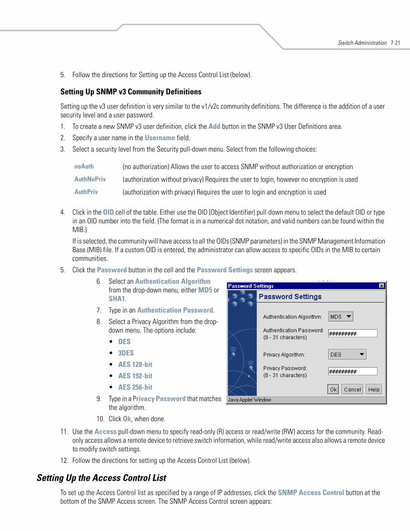
Switch Administration 7-21
5. Follow the directions for Setting up the Access Control List (below).
Setting Up SNMP v3 Community Definitions
Setting up the v3 user definition is very similar to the v1/v2c community definitions. The difference is the addition of a user security level and a user password.
1. To create a new SNMP v3 user definition, click the Add button in the SNMP v3 User Definitions area.
2. Specify a user name in the Username field.
3. Select a security level from the Security pull-down menu. Select from the following choices:
4. Click in the OID cell of the table. Either use the OID (Object Identifier) pull-down menu to select the default OID or type in an OID number into the field. (The format is in a numerical dot notation, and valid numbers can be found within the MIB.)
If is selected, the community will have access to all the OIDs (SNMP parameters) in the SNMP Management Information Base (MIB) file. If a custom OID is entered, the administrator can allow access to specific OIDs in the MIB to certain communities.
5. Click the Password button in the cell and the Password Settings screen appears.
11. Use the Access pull-down menu to specify read-only (R) access or read/write (RW) access for the community. Read-only access allows a remote device to retrieve switch information, while read/write access also allows a remote device to modify switch settings.
12. Follow the directions for setting up the Access Control List (below).
Setting Up the Access Control ListTo set up the Access Control list as specified by a range of IP addresses, click the SNMP Access Control button at the bottom of the SNMP Access screen. The SNMP Access Control screen appears:
noAuth (no authorization) Allows the user to access SNMP without authorization or encryption
AuthNoPriv (authorization without privacy) Requires the user to login, however no encryption is used
AuthPriv (authorization with privacy) Requires the user to login and encryption is used
6. Select an Authentication Algorithm from the drop-down menu, either MD5 or SHA1.
7. Type in an Authentication Password.
8. Select a Privacy Algorithm from the drop-down menu. The options include:
• DES
• 3DES
• AES 128-bit
• AES 192-bit
• AES 256-bit
9. Type in a Privacy Password that matches the algorithm.
10. Click Ok, when done.
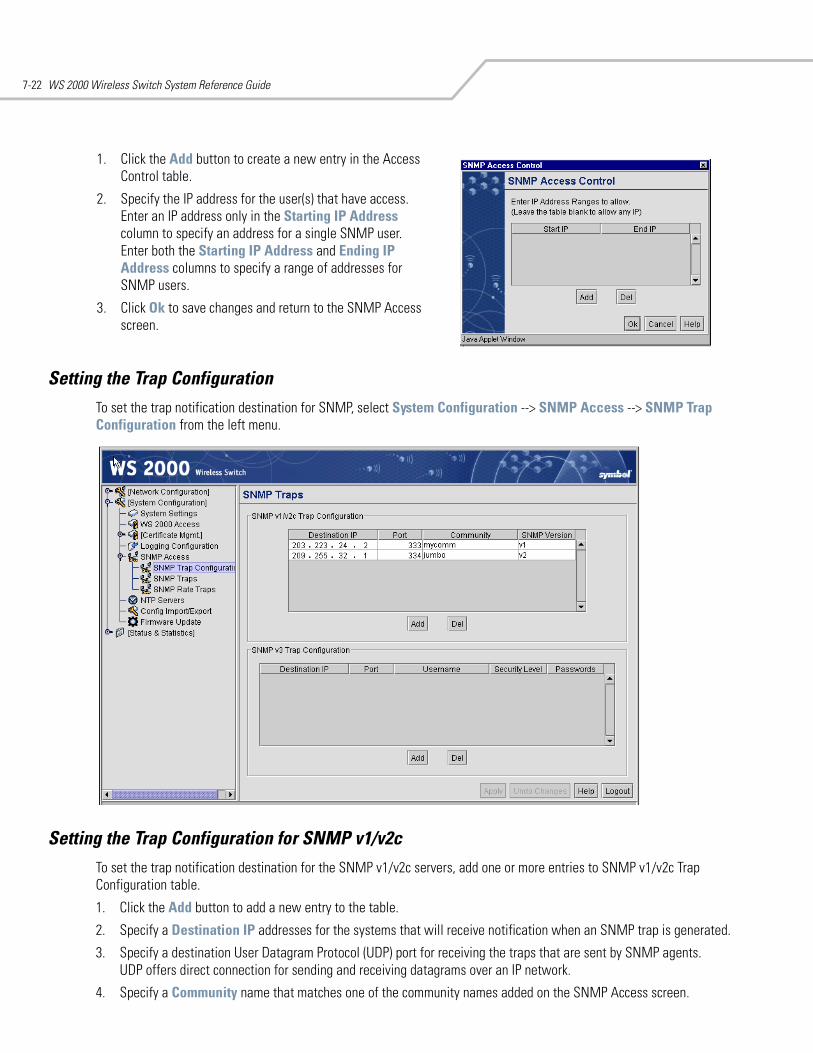
WS 2000 Wireless Switch System Reference Guide7-22
Setting the Trap Configuration To set the trap notification destination for SNMP, select System Configuration --> SNMP Access --> SNMP Trap Configuration from the left menu.
Setting the Trap Configuration for SNMP v1/v2cTo set the trap notification destination for the SNMP v1/v2c servers, add one or more entries to SNMP v1/v2c Trap Configuration table.
1. Click the Add button to add a new entry to the table.
2. Specify a Destination IP addresses for the systems that will receive notification when an SNMP trap is generated.
3. Specify a destination User Datagram Protocol (UDP) port for receiving the traps that are sent by SNMP agents.UDP offers direct connection for sending and receiving datagrams over an IP network.
4. Specify a Community name that matches one of the community names added on the SNMP Access screen.
1. Click the Add button to create a new entry in the Access Control table.
2. Specify the IP address for the user(s) that have access. Enter an IP address only in the Starting IP Address column to specify an address for a single SNMP user. Enter both the Starting IP Address and Ending IP Address columns to specify a range of addresses for SNMP users.
3. Click Ok to save changes and return to the SNMP Access screen.
Switch Administration 7-23
5. Select the appropriate SNMP Version (v1 or v2) from the pull-down menu for this particular SNMP server.
6. Click the Apply button to save the entries.
Setting the Trap Configuration for SNMP V3To set the trap notification destination for the SNMP v3 servers, add one or more entries to SNMP v3 Trap Configuration table.
1. Click the Add button to add a new entry to the table.
2. Specify a Destination IP addresses for the systems that will receive notification when an SNMP trap is generated.
3. Specify a destination User Datagram Protocol (UDP) port for receiving the traps that are sent by SNMP agents. UDP offers direct connection for sending and receiving datagrams over an IP network.
4. Specify a Username that matches one of the user names added on the SNMP Access screen.
5. Specify a Security level from noAuth (no authorization required), AuthNoPriv (authorization without encryption), or AuthPriv (authorization with encryption).
6. Specify a password for the user.
When entering the same username on the SNMP Traps and SNMP Access screens, the password entered on the SNMP Traps page will overwrite the password entered on the SNMP Access page. To avoid this problem enter the same password on both pages.
7. Click the Apply button to save changes
Selecting TrapsThe SMNP Trap screen allow the administrator to specify the types of network events that generate traps, and who to notify regarding the events. SNMP traps are generated according to predefined types of network events that are considered important to manage. This information is asynchronously reported to the switch’s SNMP network-management system by switch-managed entities. Notification is sent to the responsible individuals whose IP addresses are listed for trap notification.
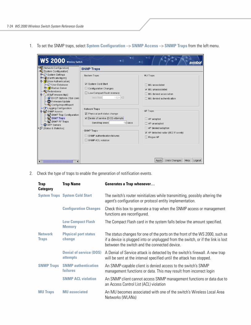
WS 2000 Wireless Switch System Reference Guide7-24
1. To set the SNMP traps, select System Configuration --> SNMP Access --> SNMP Traps from the left menu.
2. Check the type of traps to enable the generation of notification events.
Trap Category
Trap Name Generates a Trap whenever…
System Traps System Cold Start The switch’s router reinitializes while transmitting, possibly altering the agent’s configuration or protocol entity implementation.
Configuration Changes Check this box to generate a trap when the SNMP access or management functions are reconfigured.
Low Compact Flash Memory
The Compact Flash card in the system falls below the amount specified.
Network Traps
Physical port status change
The status changes for one of the ports on the front of the WS 2000, such as if a device is plugged into or unplugged from the switch, or if the link is lost between the switch and the connected device.
Denial of service (DOS) attempts
A Denial of Service attack is detected by the switch’s firewall. A new trap will be sent at the interval specified until the attack has stopped.
SNMP Traps SNMP authentication failures
An SNMP-capable client is denied access to the switch’s SNMP management functions or data. This may result from incorrect login
SNMP ACL violation An SNMP client cannot access SNMP management functions or data due to an Access Control List (ACL) violation
MU Traps MU associated An MU becomes associated with one of the switch’s Wireless Local Area Networks (WLANs)
Switch Administration 7-25
3. Click the Apply button to save the trap settings.
4. It is necessary to tell the switch where to send the notifications. Make sure to set the trap configuration to indicate where to send the notifications.
MU unassociated An MU becomes unassociated with (or gets dropped from) one of the switch’s WLANs
MU denied association An MU cannot associate with the switch-managed network, for example due to an absent or incorrectly specified MAC address on a WLAN Security screen.
MU denied authentication
An MU is denied authentication on one of the switch’s WLANs, which can be caused by the MU being set for the wrong authentication type for the WLAN or by an incorrect key or password.
AP Traps AP adopted Any of the switch’s Wireless Local Area Networks (WLANs) adopts an AP.
AP unadopted Any of the switch’s WLANs unadopts (or drops) an AP.
AP denied adoption Check this box to generate a trap when any of the switch’s WLANs deny the adoption of an AP.
AP detected radar (802.11a only)
An 802.11a AP 300 Access Port detects radar during its startup or ongoing radar scans. This trap only applies to the 802.11a radio of an AP 300 Access Port operating with Dynamic Frequency Selection and Transmit Power Control (DFS/TPC).
Rogue AP Check this box to generate a trap when a rogue (unauthorized) access port (AP) is detected. Several methods for rogue AP detection are employed by the switch. The detection process is non-disruptive and will not affect the performance of the switch. The detection functionality is greatly enhanced when the Approved AP list is filled out on the AP List screen under Rogue AP Detection.
Trap Category
Trap Name Generates a Trap whenever…
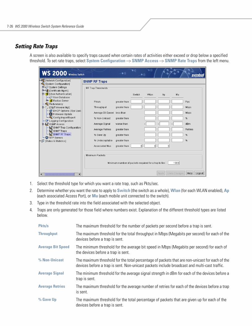
WS 2000 Wireless Switch System Reference Guide7-26
Setting Rate TrapsA screen is also available to specify traps caused when certain rates of activities either exceed or drop below a specified threshold. To set rate traps, select System Configuration --> SNMP Access --> SNMP Rate Traps from the left menu.
1. Select the threshold type for which you want a rate trap, such as Pkts/sec.
2. Determine whether you want the rate to apply to Switch (the switch as a whole), Wlan (for each WLAN enabled), Ap (each associated Access Port), or Mu (each mobile unit connected to the switch).
3. Type in the threshold rate into the field associated with the selected object.
4. Traps are only generated for those field where numbers exist. Explanation of the different threshold types are listed below.
Pkts/s The maximum threshold for the number of packets per second before a trap is sent.
Throughput The maximum threshold for the total throughput in Mbps (Megabits per second) for each of the devices before a trap is sent.
Average Bit Speed The minimum threshold for the average bit speed in Mbps (Megabits per second) for each of the devices before a trap is sent.
% Non-Unicast The maximum threshold for the total percentage of packets that are non-unicast for each of the devices before a trap is sent. Non-unicast packets include broadcast and multi-cast traffic.
Average Signal The minimum threshold for the average signal strength in dBm for each of the devices before a trap is sent.
Average Retries The maximum threshold for the average number of retries for each of the devices before a trap is sent.
% Gave Up The maximum threshold for the total percentage of packets that are given up for each of the devices before a trap is sent.
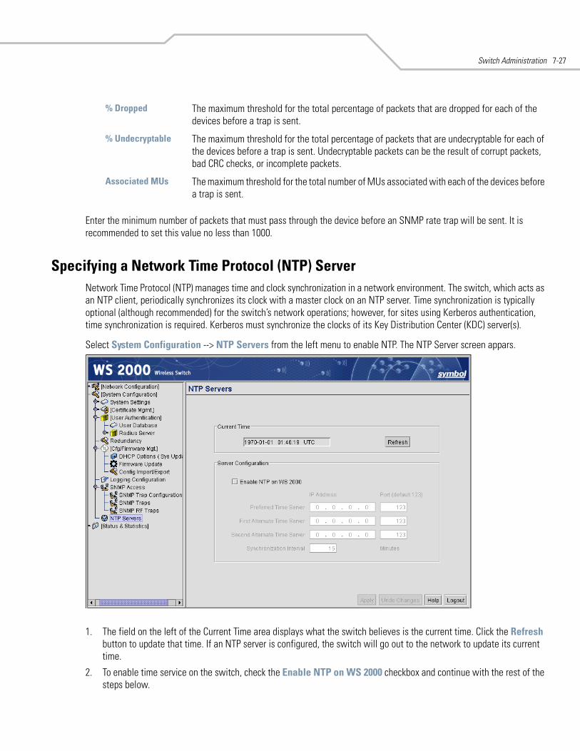
Switch Administration 7-27
Enter the minimum number of packets that must pass through the device before an SNMP rate trap will be sent. It is recommended to set this value no less than 1000.
Specifying a Network Time Protocol (NTP) ServerNetwork Time Protocol (NTP) manages time and clock synchronization in a network environment. The switch, which acts as an NTP client, periodically synchronizes its clock with a master clock on an NTP server. Time synchronization is typically optional (although recommended) for the switch’s network operations; however, for sites using Kerberos authentication, time synchronization is required. Kerberos must synchronize the clocks of its Key Distribution Center (KDC) server(s).
Select System Configuration --> NTP Servers from the left menu to enable NTP. The NTP Server screen appars.
1. The field on the left of the Current Time area displays what the switch believes is the current time. Click the Refresh button to update that time. If an NTP server is configured, the switch will go out to the network to update its current time.
2. To enable time service on the switch, check the Enable NTP on WS 2000 checkbox and continue with the rest of the steps below.
% Dropped The maximum threshold for the total percentage of packets that are dropped for each of the devices before a trap is sent.
% Undecryptable The maximum threshold for the total percentage of packets that are undecryptable for each of the devices before a trap is sent. Undecryptable packets can be the result of corrupt packets, bad CRC checks, or incomplete packets.
Associated MUs The maximum threshold for the total number of MUs associated with each of the devices before a trap is sent.
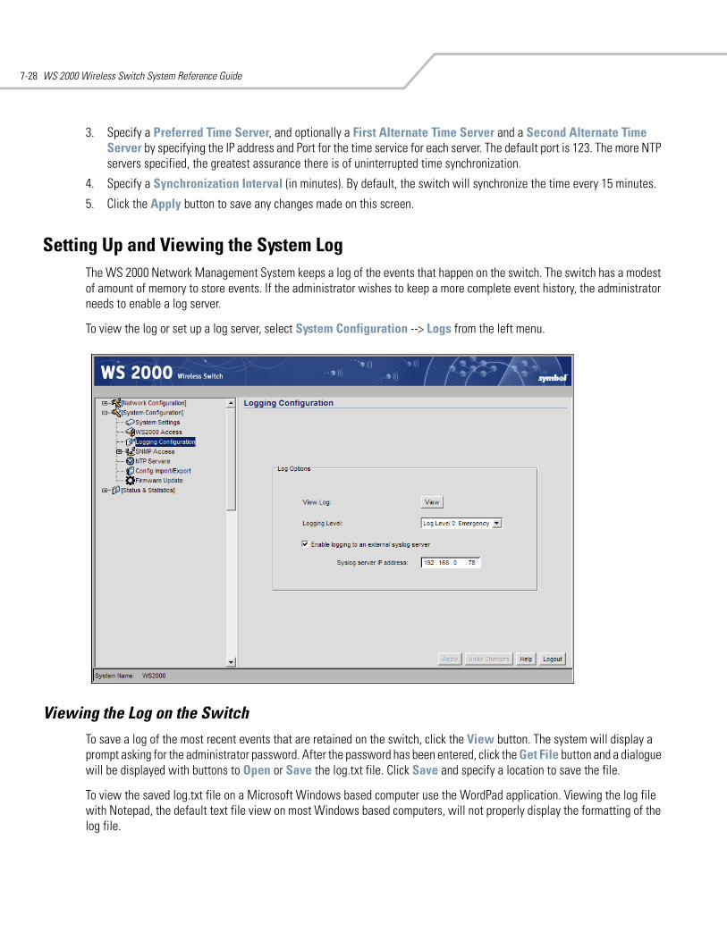
WS 2000 Wireless Switch System Reference Guide7-28
3. Specify a Preferred Time Server, and optionally a First Alternate Time Server and a Second Alternate Time Server by specifying the IP address and Port for the time service for each server. The default port is 123. The more NTP servers specified, the greatest assurance there is of uninterrupted time synchronization.
4. Specify a Synchronization Interval (in minutes). By default, the switch will synchronize the time every 15 minutes.
5. Click the Apply button to save any changes made on this screen.
Setting Up and Viewing the System LogThe WS 2000 Network Management System keeps a log of the events that happen on the switch. The switch has a modest of amount of memory to store events. If the administrator wishes to keep a more complete event history, the administrator needs to enable a log server.
To view the log or set up a log server, select System Configuration --> Logs from the left menu.
Viewing the Log on the SwitchTo save a log of the most recent events that are retained on the switch, click the View button. The system will display a prompt asking for the administrator password. After the password has been entered, click the Get File button and a dialogue will be displayed with buttons to Open or Save the log.txt file. Click Save and specify a location to save the file.
To view the saved log.txt file on a Microsoft Windows based computer use the WordPad application. Viewing the log file with Notepad, the default text file view on most Windows based computers, will not properly display the formatting of the log file.
Switch Administration 7-29
Setting Up a Log ServerTo keep a complete history of the events that are logged by the switch, the administrator needs to set up an external system log on a server. The server listens for incoming switch-generated syslog messages on a UDP port (514 by default), and then decodes the messages into a log file appropriate for viewing and printing. Events are categorized into eight levels (0 through 7), with the lowest numbers representing the most critical issues.
1. Set the level of the errors to be logged from the Logging Level drop-down menu. All events associated with the selected level and events with levels lower than the selection will be recorded.
2. Check the Enable logging in to an external syslog server checkbox to enable logging.
3. Specify the Syslog server IP address for the server that will store the log.
4. Select Apply to save the changes.
5. Select Network Configuration --> Subnet Access. Work through all the combinations of subnet-to-WAN accesses to ensure that DNS communications are allowed. (UDP must be enabled to save the log entries.)

WS 2000 Wireless Switch System Reference Guide7-30
8Status & Statistics
WAN Statistics. . . . . . . . . . . . . . . . . . . . . . . . . . . . . . . . . . . . . . . . . . . . . . . . . . . . . . . . . . . . . . . . . . . . . . . . . . . 8-2Subnet Statistics . . . . . . . . . . . . . . . . . . . . . . . . . . . . . . . . . . . . . . . . . . . . . . . . . . . . . . . . . . . . . . . . . . . . . . . . . 8-3
Interfaces . . . . . . . . . . . . . . . . . . . . . . . . . . . . . . . . . . . . . . . . . . . . . . . . . . . . . . . . . . . . . . . . . . . . . . . . . . . 8-5Wireless LAN Statistics . . . . . . . . . . . . . . . . . . . . . . . . . . . . . . . . . . . . . . . . . . . . . . . . . . . . . . . . . . . . . . . . . . . . 8-6
Displaying WLAN Summary Information . . . . . . . . . . . . . . . . . . . . . . . . . . . . . . . . . . . . . . . . . . . . . . . . . . . 8-6Getting Statistics for a Particular WLAN. . . . . . . . . . . . . . . . . . . . . . . . . . . . . . . . . . . . . . . . . . . . . . . . . . . 8-7General WLAN Information . . . . . . . . . . . . . . . . . . . . . . . . . . . . . . . . . . . . . . . . . . . . . . . . . . . . . . . . . . . . . 8-8
Access Port Statistics. . . . . . . . . . . . . . . . . . . . . . . . . . . . . . . . . . . . . . . . . . . . . . . . . . . . . . . . . . . . . . . . . . . . . . 8-9Access Port Statistics Summary Screen . . . . . . . . . . . . . . . . . . . . . . . . . . . . . . . . . . . . . . . . . . . . . . . . . . . 8-9Detailed Information About a Particular Access Port . . . . . . . . . . . . . . . . . . . . . . . . . . . . . . . . . . . . . . . . 8-10General Access Port Information . . . . . . . . . . . . . . . . . . . . . . . . . . . . . . . . . . . . . . . . . . . . . . . . . . . . . . . . 8-11
Mobile Unit (MU) Statistics . . . . . . . . . . . . . . . . . . . . . . . . . . . . . . . . . . . . . . . . . . . . . . . . . . . . . . . . . . . . . . . . 8-13View Statistics in Graphic Form. . . . . . . . . . . . . . . . . . . . . . . . . . . . . . . . . . . . . . . . . . . . . . . . . . . . . . . . . . . . . 8-14
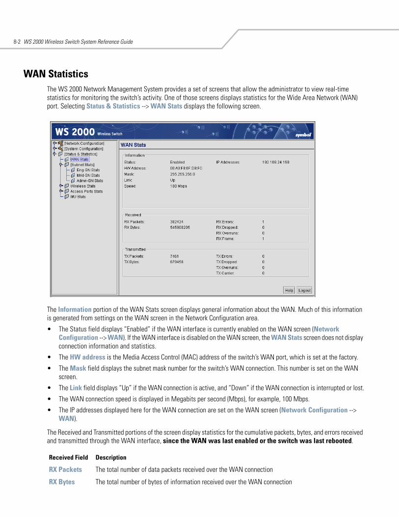
WS 2000 Wireless Switch System Reference Guide8-2
WAN StatisticsThe WS 2000 Network Management System provides a set of screens that allow the administrator to view real-time statistics for monitoring the switch’s activity. One of those screens displays statistics for the Wide Area Network (WAN) port. Selecting Status & Statistics --> WAN Stats displays the following screen.
The Information portion of the WAN Stats screen displays general information about the WAN. Much of this information is generated from settings on the WAN screen in the Network Configuration area.
• The Status field displays “Enabled” if the WAN interface is currently enabled on the WAN screen (Network Configuration --> WAN). If the WAN interface is disabled on the WAN screen, the WAN Stats screen does not display connection information and statistics.
• The HW address is the Media Access Control (MAC) address of the switch’s WAN port, which is set at the factory.
• The Mask field displays the subnet mask number for the switch’s WAN connection. This number is set on the WAN screen.
• The Link field displays “Up” if the WAN connection is active, and “Down” if the WAN connection is interrupted or lost.
• The WAN connection speed is displayed in Megabits per second (Mbps), for example, 100 Mbps.
• The IP addresses displayed here for the WAN connection are set on the WAN screen (Network Configuration --> WAN).
The Received and Transmitted portions of the screen display statistics for the cumulative packets, bytes, and errors received and transmitted through the WAN interface, since the WAN was last enabled or the switch was last rebooted.
Received Field Description
RX Packets The total number of data packets received over the WAN connection
RX Bytes The total number of bytes of information received over the WAN connection
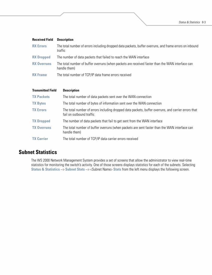
Status & Statistics 8-3
Subnet StatisticsThe WS 2000 Network Management System provides a set of screens that allow the administrator to view real-time statistics for monitoring the switch’s activity. One of those screens displays statistics for each of the subnets. Selecting Status & Statistics --> Subnet Stats --> <Subnet Name> Stats from the left menu displays the following screen.
RX Errors The total number of errors including dropped data packets, buffer overruns, and frame errors on inbound traffic
RX Dropped The number of data packets that failed to reach the WAN interface
RX Overruns The total number of buffer overruns (when packets are received faster than the WAN interface can handle them)
RX Frame The total number of TCP/IP data frame errors received
Transmitted Field Description
TX Packets The total number of data packets sent over the WAN connection
TX Bytes The total number of bytes of information sent over the WAN connection
TX Errors The total number of errors including dropped data packets, buffer overruns, and carrier errors that fail on outbound traffic
TX Dropped The number of data packets that fail to get sent from the WAN interface
TX Overruns The total number of buffer overruns (when packets are sent faster than the WAN interface can handle them)
TX Carrier The total number of TCP/IP data carrier errors received
Received Field Description
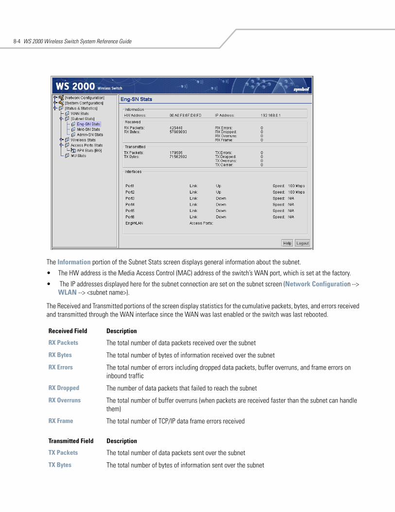
WS 2000 Wireless Switch System Reference Guide8-4
The Information portion of the Subnet Stats screen displays general information about the subnet.
• The HW address is the Media Access Control (MAC) address of the switch’s WAN port, which is set at the factory.
• The IP addresses displayed here for the subnet connection are set on the subnet screen (Network Configuration --> WLAN --> <subnet name>).
The Received and Transmitted portions of the screen display statistics for the cumulative packets, bytes, and errors received and transmitted through the WAN interface since the WAN was last enabled or the switch was last rebooted.
Received Field Description
RX Packets The total number of data packets received over the subnet
RX Bytes The total number of bytes of information received over the subnet
RX Errors The total number of errors including dropped data packets, buffer overruns, and frame errors on inbound traffic
RX Dropped The number of data packets that failed to reach the subnet
RX Overruns The total number of buffer overruns (when packets are received faster than the subnet can handle them)
RX Frame The total number of TCP/IP data frame errors received
Transmitted Field Description
TX Packets The total number of data packets sent over the subnet
TX Bytes The total number of bytes of information sent over the subnet
Status & Statistics 8-5
InterfacesThe interfaces section of the screen displays information about the ports and Access Ports associated with the subnet (set in Network Configuration --> Subnet --> <Subnet Name>).
The area shows the status of the port-subnet link and the speed of the connection. The Link field displays “Up” if the adjacent port is active, and “Down” if the adjacent port is inactive.
The area also shows the status of the port-WLAN associations. In this case, the adopted Access Ports for each of the associated WLANs are listed.
TX Errors The total number of errors including dropped data packets, buffer overruns, and carrier errors that fail on outbound traffic
TX Dropped The number of data packets that fail to get sent from the subnet
TX Overruns The total number of buffer overruns (when packets are sent faster than the subnet can handle them)
TX Carrier The total number of TCP/IP data carrier errors received
Transmitted Field Description
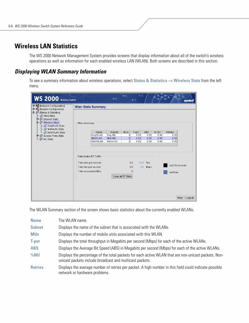
WS 2000 Wireless Switch System Reference Guide8-6
Wireless LAN StatisticsThe WS 2000 Network Management System provides screens that display information about all of the switch’s wireless operations as well as information for each enabled wireless LAN (WLAN). Both screens are described in this section.
Displaying WLAN Summary InformationTo see a summary information about wireless operations, select Status & Statistics --> Wireless Stats from the left menu.
The WLAN Summary section of the screen shows basic statistics about the currently enabled WLANs.
Name The WLAN name.
Subnet Displays the name of the subnet that is associated with the WLANs.
MUs Displays the number of mobile units associated with this WLAN.
T-put Displays the total throughput in Megabits per second (Mbps) for each of the active WLANs.
ABS Displays the Average Bit Speed (ABS) in Megabits per second (Mbps) for each of the active WLANs.
%NU Displays the percentage of the total packets for each active WLAN that are non-unicast packets. Non-unicast packets include broadcast and multicast packets.
Retries Displays the average number of retries per packet. A high number in this field could indicate possible network or hardware problems.
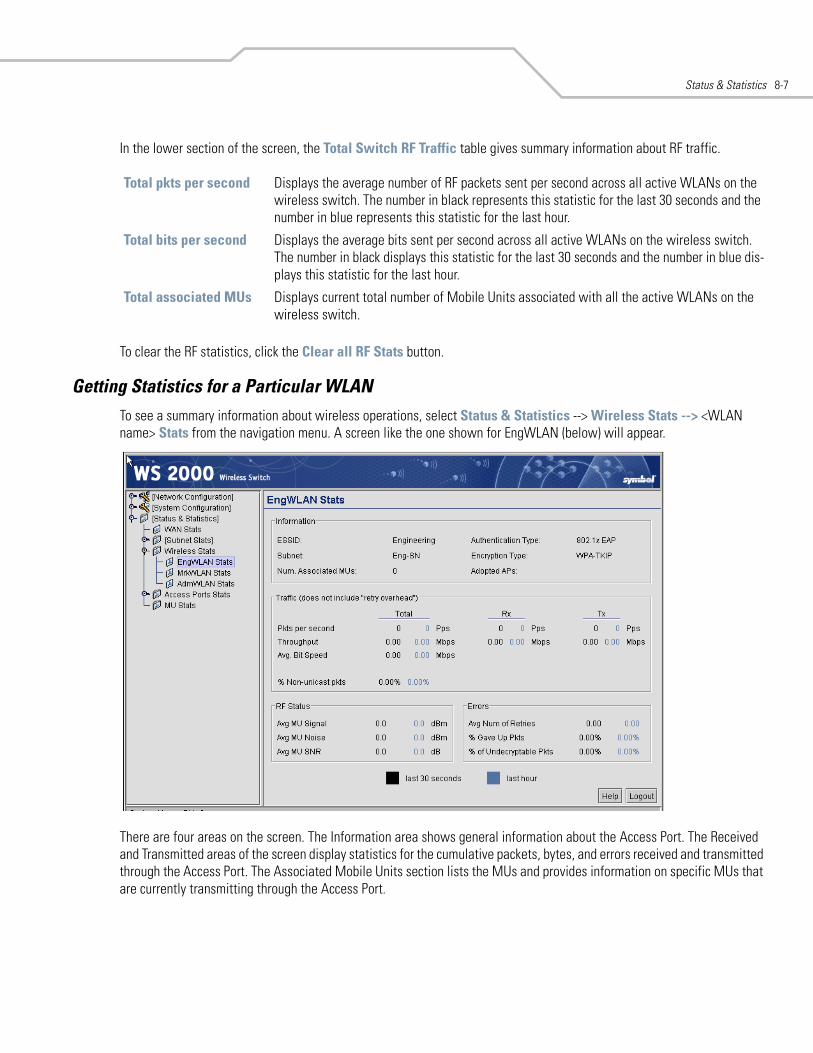
Status & Statistics 8-7
In the lower section of the screen, the Total Switch RF Traffic table gives summary information about RF traffic.
To clear the RF statistics, click the Clear all RF Stats button.
Getting Statistics for a Particular WLANTo see a summary information about wireless operations, select Status & Statistics --> Wireless Stats --> <WLAN name> Stats from the navigation menu. A screen like the one shown for EngWLAN (below) will appear.
There are four areas on the screen. The Information area shows general information about the Access Port. The Received and Transmitted areas of the screen display statistics for the cumulative packets, bytes, and errors received and transmitted through the Access Port. The Associated Mobile Units section lists the MUs and provides information on specific MUs that are currently transmitting through the Access Port.
Total pkts per second Displays the average number of RF packets sent per second across all active WLANs on the wireless switch. The number in black represents this statistic for the last 30 seconds and the number in blue represents this statistic for the last hour.
Total bits per second Displays the average bits sent per second across all active WLANs on the wireless switch. The number in black displays this statistic for the last 30 seconds and the number in blue dis-plays this statistic for the last hour.
Total associated MUs Displays current total number of Mobile Units associated with all the active WLANs on the wireless switch.
WS 2000 Wireless Switch System Reference Guide8-8
General WLAN Information
Information Section
Traffic Area
RF Status
ESSID Displays the Extended Service Set Identification name that users will see when accessing the WLAN.
Subnet Displays the name of the subnet to which this WLAN is associated.
Num. Associated MUs
Lists the number of mobile units (MUs) currently associated with the Access Port.
Authentication Type Displays the type of authentication used with this WLAN.
Encryption Type Displays type of encryption used with this WLAN.
Adopted APs Lists the Access Ports that have been adopted by this WLAN.
Packets per second The Total column displays the average total packets per second that cross the selected WLAN. The Rx column displays the average total packets per second received on the selected WLAN. The Tx column displays the average total packets per second sent on the selected WLAN. The number in black represents this statistic for the last 30 seconds and the number in blue repre-sents this statistic for the last hour.
Throughput The Total column displays the average throughput in Mbps for a given time period on the selected WLAN. The Rx column displays the average throughput in Mbps for packets received on the selected WLAN. The Tx column displays the average throughput for packets sent on the WLAN WLAN. The number in black represents this statistic for the last 30 seconds and the num-ber in blue represents this statistic for the last hour.
Avg. Bit Speed The Total column displays the average bit speed in Mbps for a given time period on the selected WLAN.This includes all packets that are sent and received. The number in black represents this statistic for the last 30 seconds and the number in blue represents this statistic for the last hour.
% Non-unicast pkts Displays the percentage of the total packets for the selected WLAN that are non-unicast pack-ets. Non-unicast packets include broadcast and multicast packets.The number in black repre-sents this statistic for the last 30 seconds and the number in blue represents this statistic for the last hour.
Avg MU Signal Displays the average RF signal strength in dBm for all MUs associated with the selected WLAN. The number in black represents this statistic for the last 30 seconds and the number in blue rep-resents this statistic for the last hour.
Avg MU Noise Displays the average RF noise for all MUs associated with the selected WLAN. The number in black represents this statistic for the last 30 seconds and the number in blue represents this sta-tistic for the last hour.
Avg MU SNR Displays the average Signal to Noise Ratio (SNR) for all MUs associated with the selected WLAN. The Signal to Noise Ratio is an indication of overall RF performance on your wireless net-works.
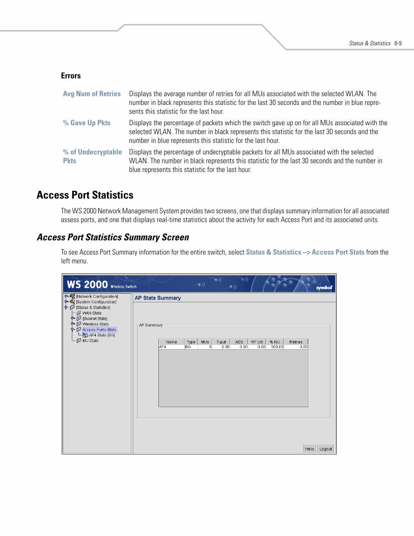
Status & Statistics 8-9
Errors
Access Port StatisticsThe WS 2000 Network Management System provides two screens, one that displays summary information for all associated assess ports, and one that displays real-time statistics about the activity for each Access Port and its associated units.
Access Port Statistics Summary ScreenTo see Access Port Summary information for the entire switch, select Status & Statistics --> Access Port Stats from the left menu.
Avg Num of Retries Displays the average number of retries for all MUs associated with the selected WLAN. The number in black represents this statistic for the last 30 seconds and the number in blue repre-sents this statistic for the last hour.
% Gave Up Pkts Displays the percentage of packets which the switch gave up on for all MUs associated with the selected WLAN. The number in black represents this statistic for the last 30 seconds and the number in blue represents this statistic for the last hour.
% of Undecryptable Pkts
Displays the percentage of undecryptable packets for all MUs associated with the selected WLAN. The number in black represents this statistic for the last 30 seconds and the number in blue represents this statistic for the last hour.
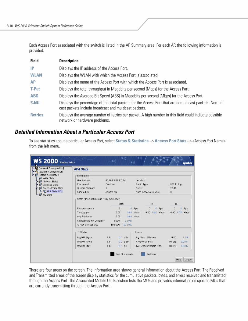
WS 2000 Wireless Switch System Reference Guide8-10
Each Access Port associated with the switch is listed in the AP Summary area. For each AP, the following information is provided.
Detailed Information About a Particular Access Port To see statistics about a particular Access Port, select Status & Statistics --> Access Port Stats --> <Access Port Name> from the left menu.
There are four areas on the screen. The Information area shows general information about the Access Port. The Received and Transmitted areas of the screen display statistics for the cumulative packets, bytes, and errors received and transmitted through the Access Port. The Associated Mobile Units section lists the MUs and provides information on specific MUs that are currently transmitting through the Access Port.
Field Description
IP Displays the IP address of the Access Port.
WLAN Displays the WLAN with which the Access Port is associated.
AP Displays the name of the Access Port with which the Access Port is associated.
T-Put Displays the total throughput in Megabits per second (Mbps) for the Access Port.
ABS Displays the Average Bit Speed (ABS) in Megabits per second (Mbps) for the Access Port.
%NU Displays the percentage of the total packets for the Access Port that are non-unicast packets. Non-uni-cast packets include broadcast and multicast packets.
Retries Displays the average number of retries per packet. A high number in this field could indicate possible network or hardware problems.
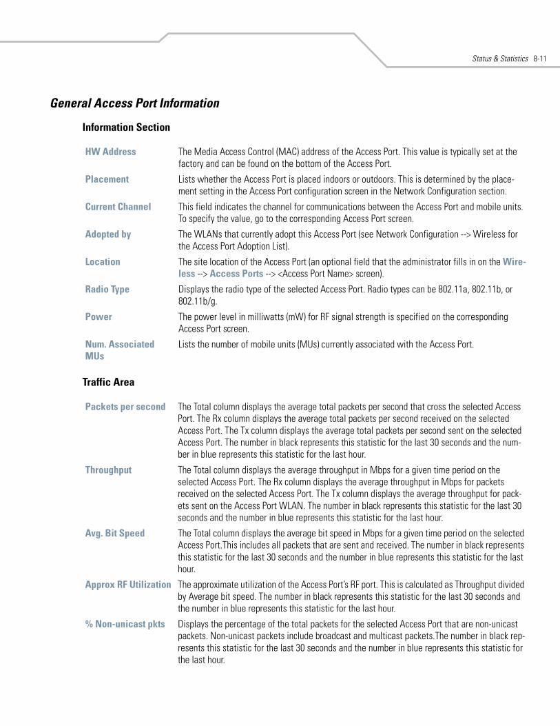
Status & Statistics 8-11
General Access Port Information
Information Section
Traffic Area
HW Address The Media Access Control (MAC) address of the Access Port. This value is typically set at the factory and can be found on the bottom of the Access Port.
Placement Lists whether the Access Port is placed indoors or outdoors. This is determined by the place-ment setting in the Access Port configuration screen in the Network Configuration section.
Current Channel This field indicates the channel for communications between the Access Port and mobile units. To specify the value, go to the corresponding Access Port screen.
Adopted by The WLANs that currently adopt this Access Port (see Network Configuration --> Wireless for the Access Port Adoption List).
Location The site location of the Access Port (an optional field that the administrator fills in on the Wire-less --> Access Ports --> <Access Port Name> screen).
Radio Type Displays the radio type of the selected Access Port. Radio types can be 802.11a, 802.11b, or 802.11b/g.
Power The power level in milliwatts (mW) for RF signal strength is specified on the corresponding Access Port screen.
Num. Associated MUs
Lists the number of mobile units (MUs) currently associated with the Access Port.
Packets per second The Total column displays the average total packets per second that cross the selected Access Port. The Rx column displays the average total packets per second received on the selected Access Port. The Tx column displays the average total packets per second sent on the selected Access Port. The number in black represents this statistic for the last 30 seconds and the num-ber in blue represents this statistic for the last hour.
Throughput The Total column displays the average throughput in Mbps for a given time period on the selected Access Port. The Rx column displays the average throughput in Mbps for packets received on the selected Access Port. The Tx column displays the average throughput for pack-ets sent on the Access Port WLAN. The number in black represents this statistic for the last 30 seconds and the number in blue represents this statistic for the last hour.
Avg. Bit Speed The Total column displays the average bit speed in Mbps for a given time period on the selected Access Port.This includes all packets that are sent and received. The number in black represents this statistic for the last 30 seconds and the number in blue represents this statistic for the last hour.
Approx RF Utilization The approximate utilization of the Access Port’s RF port. This is calculated as Throughput divided by Average bit speed. The number in black represents this statistic for the last 30 seconds and the number in blue represents this statistic for the last hour.
% Non-unicast pkts Displays the percentage of the total packets for the selected Access Port that are non-unicast packets. Non-unicast packets include broadcast and multicast packets.The number in black rep-resents this statistic for the last 30 seconds and the number in blue represents this statistic for the last hour.
WS 2000 Wireless Switch System Reference Guide8-12
RF Status
Errors
Avg MU Signal Displays the average RF signal strength in dBm for all MUs associated with the selected Access Port. The number in black represents this statistic for the last 30 seconds and the number in blue represents this statistic for the last hour.
Avg MU Noise Displays the average RF noise for all MUs associated with the selected Access Port. The number in black represents this statistic for the last 30 seconds and the number in blue represents this statistic for the last hour.
Avg MU SNR Displays the average Signal to Noise Ratio (SNR) for all MUs associated with the selected Access Port. The Signal to Noise Ratio is an indication of overall RF performance on your wireless networks.
Avg Num of Retries Displays the average number of retries for all MUs associated with the selected Access Port. The number in black represents this statistic for the last 30 seconds and the number in blue repre-sents this statistic for the last hour.
% Gave Up Pkts Displays the percentage of packets which the switch gave up on for all MUs associated with the selected Access Port. The number in black represents this statistic for the last 30 seconds and the number in blue represents this statistic for the last hour.
% of Undecryptable Pkts
Displays the percentage of undecryptable packets for all MUs associated with the selected Access Port. The number in black represents this statistic for the last 30 seconds and the number in blue represents this statistic for the last hour.
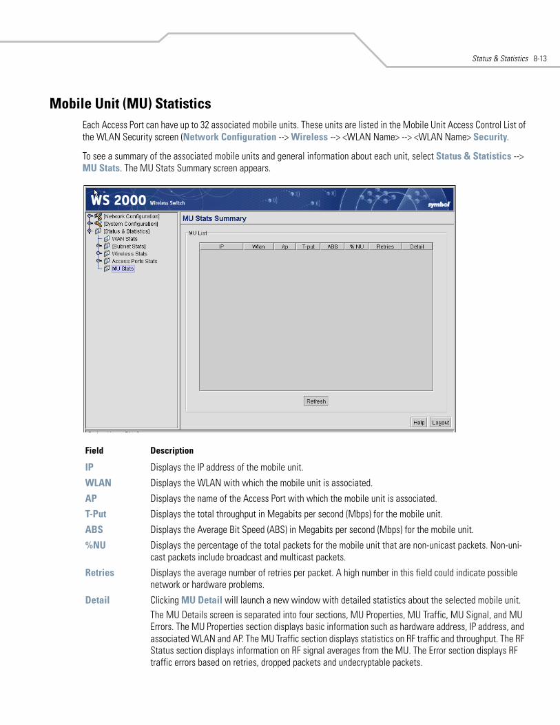
Status & Statistics 8-13
Mobile Unit (MU) StatisticsEach Access Port can have up to 32 associated mobile units. These units are listed in the Mobile Unit Access Control List of the WLAN Security screen (Network Configuration --> Wireless --> <WLAN Name> --> <WLAN Name> Security.
To see a summary of the associated mobile units and general information about each unit, select Status & Statistics --> MU Stats. The MU Stats Summary screen appears.
Field Description
IP Displays the IP address of the mobile unit.
WLAN Displays the WLAN with which the mobile unit is associated.
AP Displays the name of the Access Port with which the mobile unit is associated.
T-Put Displays the total throughput in Megabits per second (Mbps) for the mobile unit.
ABS Displays the Average Bit Speed (ABS) in Megabits per second (Mbps) for the mobile unit.
%NU Displays the percentage of the total packets for the mobile unit that are non-unicast packets. Non-uni-cast packets include broadcast and multicast packets.
Retries Displays the average number of retries per packet. A high number in this field could indicate possible network or hardware problems.
Detail Clicking MU Detail will launch a new window with detailed statistics about the selected mobile unit.The MU Details screen is separated into four sections, MU Properties, MU Traffic, MU Signal, and MU Errors. The MU Properties section displays basic information such as hardware address, IP address, and associated WLAN and AP. The MU Traffic section displays statistics on RF traffic and throughput. The RF Status section displays information on RF signal averages from the MU. The Error section displays RF traffic errors based on retries, dropped packets and undecryptable packets.
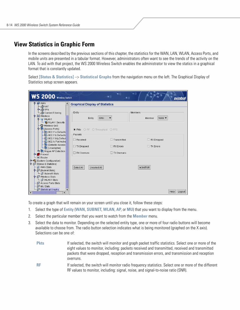
WS 2000 Wireless Switch System Reference Guide8-14
View Statistics in Graphic FormIn the screens described by the previous sections of this chapter, the statistics for the WAN, LAN, WLAN, Access Ports, and mobile units are presented in a tabular format. However, administrators often want to see the trends of the activity on the LAN. To aid with that project, the WS 2000 Wireless Switch enables the administrator to view the statics in a graphical format that is constantly updated.
Select [Status & Statistics] --> Statistical Graphs from the navigation menu on the left. The Graphical Display of Statistics setup screen appears.
To create a graph that will remain on your screen until you close it, follow these steps:
1. Select the type of Entity (WAN, SUBNET, WLAN, AP, or MU) that you want to display from the menu.
2. Select the particular member that you want to watch from the Member menu.
3. Select the data to monitor. Depending on the selected entity type, one or more of four radio buttons will become available to choose from. The radio button selection indicates what is being monitored (graphed on the X axis). Selections can be one of:
Pkts If selected, the switch will monitor and graph packet traffic statistics. Select one or more of the eight values to monitor, including: packets received and transmitted, received and transmitted packets that were dropped, reception and transmission errors, and transmission and reception overruns.
RF If selected, the switch will monitor radio frequency statistics. Select one or more of the different RF values to monitor, including: signal, noise, and signal-to-noise ratio (SNR).
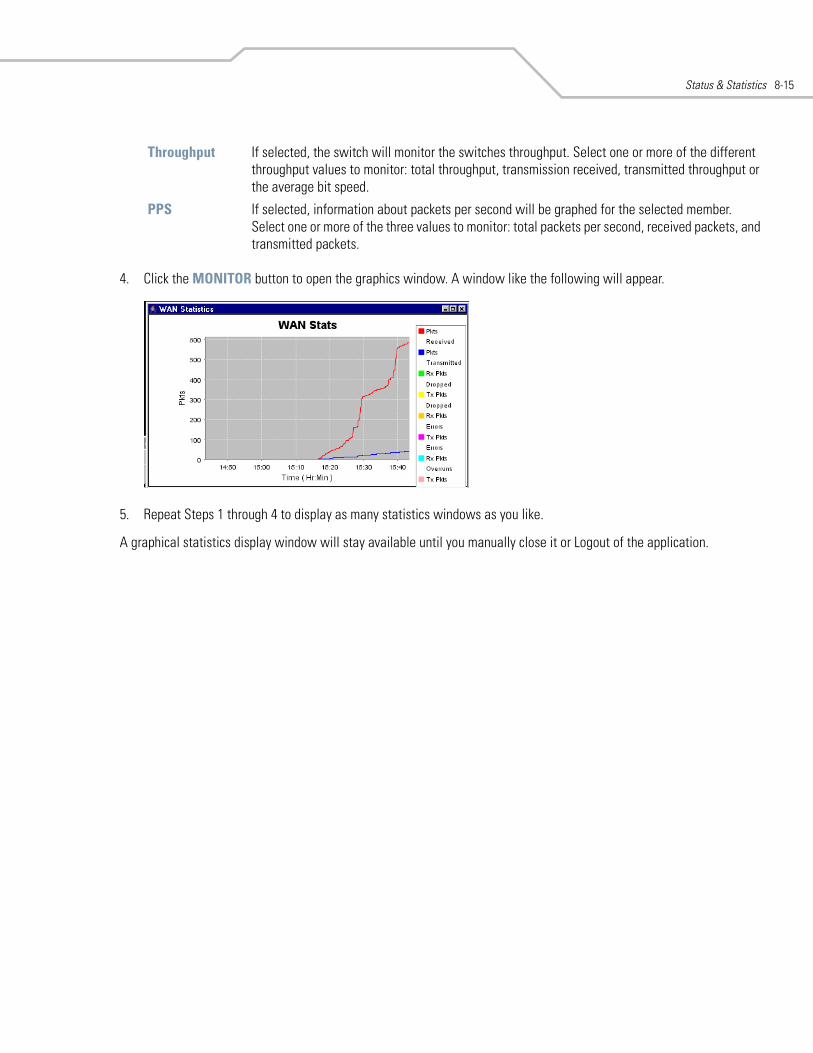
Status & Statistics 8-15
4. Click the MONITOR button to open the graphics window. A window like the following will appear.
5. Repeat Steps 1 through 4 to display as many statistics windows as you like.
A graphical statistics display window will stay available until you manually close it or Logout of the application.
Throughput If selected, the switch will monitor the switches throughput. Select one or more of the different throughput values to monitor: total throughput, transmission received, transmitted throughput or the average bit speed.
PPS If selected, information about packets per second will be graphed for the selected member. Select one or more of the three values to monitor: total packets per second, received packets, and transmitted packets.

WS 2000 Wireless Switch System Reference Guide8-16
9WS 2000 Use Cases
Retail Use Case . . . . . . . . . . . . . . . . . . . . . . . . . . . . . . . . . . . . . . . . . . . . . . . . . . . . . . . . . . . . . . . . . . . . . . . . . . 9-3A Retail Example . . . . . . . . . . . . . . . . . . . . . . . . . . . . . . . . . . . . . . . . . . . . . . . . . . . . . . . . . . . . . . . . . . . . . 9-3
The Plan . . . . . . . . . . . . . . . . . . . . . . . . . . . . . . . . . . . . . . . . . . . . . . . . . . . . . . . . . . . . . . . . . . . . . . . . . . . . . . . . 9-3Contacting the Wireless Switch . . . . . . . . . . . . . . . . . . . . . . . . . . . . . . . . . . . . . . . . . . . . . . . . . . . . . . . . . . . . . 9-4
Entering the Basic System Settings. . . . . . . . . . . . . . . . . . . . . . . . . . . . . . . . . . . . . . . . . . . . . . . . . . . . . . . 9-5Setting Access Control. . . . . . . . . . . . . . . . . . . . . . . . . . . . . . . . . . . . . . . . . . . . . . . . . . . . . . . . . . . . . . . . . 9-6The IP Address Plan . . . . . . . . . . . . . . . . . . . . . . . . . . . . . . . . . . . . . . . . . . . . . . . . . . . . . . . . . . . . . . . . . . . 9-7
Configuring POS Subnet. . . . . . . . . . . . . . . . . . . . . . . . . . . . . . . . . . . . . . . . . . . . . . . . . . . . . . . . . . . . . . . . . . . . 9-8Configuring the Printer Subnet. . . . . . . . . . . . . . . . . . . . . . . . . . . . . . . . . . . . . . . . . . . . . . . . . . . . . . . . . . . . . . . 9-9Configuring the Cafe Subnet . . . . . . . . . . . . . . . . . . . . . . . . . . . . . . . . . . . . . . . . . . . . . . . . . . . . . . . . . . . . . . . 9-11Configuring the WAN Interface . . . . . . . . . . . . . . . . . . . . . . . . . . . . . . . . . . . . . . . . . . . . . . . . . . . . . . . . . . . . . 9-13Configuring Network Address Translation (NAT) . . . . . . . . . . . . . . . . . . . . . . . . . . . . . . . . . . . . . . . . . . . . . . . 9-14Inspecting the Firewall . . . . . . . . . . . . . . . . . . . . . . . . . . . . . . . . . . . . . . . . . . . . . . . . . . . . . . . . . . . . . . . . . . . . 9-16Configuring the Access Ports . . . . . . . . . . . . . . . . . . . . . . . . . . . . . . . . . . . . . . . . . . . . . . . . . . . . . . . . . . . . . . . 9-16
Setting Access Port Defaults . . . . . . . . . . . . . . . . . . . . . . . . . . . . . . . . . . . . . . . . . . . . . . . . . . . . . . . . . . . 9-17Naming the POS Access Port . . . . . . . . . . . . . . . . . . . . . . . . . . . . . . . . . . . . . . . . . . . . . . . . . . . . . . . . . . . 9-18Configuring the Printer Access Port . . . . . . . . . . . . . . . . . . . . . . . . . . . . . . . . . . . . . . . . . . . . . . . . . . . . . . 9-19Configuring the Cafe Access Port . . . . . . . . . . . . . . . . . . . . . . . . . . . . . . . . . . . . . . . . . . . . . . . . . . . . . . . 9-20Associating the Access Ports to the WLANs. . . . . . . . . . . . . . . . . . . . . . . . . . . . . . . . . . . . . . . . . . . . . . . 9-21
Configuring the Cafe WLAN. . . . . . . . . . . . . . . . . . . . . . . . . . . . . . . . . . . . . . . . . . . . . . . . . . . . . . . . . . . . . . . . 9-22Configuring the Printer WLAN . . . . . . . . . . . . . . . . . . . . . . . . . . . . . . . . . . . . . . . . . . . . . . . . . . . . . . . . . . . . . . 9-24Configuring the POS WLAN . . . . . . . . . . . . . . . . . . . . . . . . . . . . . . . . . . . . . . . . . . . . . . . . . . . . . . . . . . . . . . . . 9-26Configuring Subnet Access . . . . . . . . . . . . . . . . . . . . . . . . . . . . . . . . . . . . . . . . . . . . . . . . . . . . . . . . . . . . . . . . 9-29Configuring the Clients. . . . . . . . . . . . . . . . . . . . . . . . . . . . . . . . . . . . . . . . . . . . . . . . . . . . . . . . . . . . . . . . . . . . 9-31
Testing Connections. . . . . . . . . . . . . . . . . . . . . . . . . . . . . . . . . . . . . . . . . . . . . . . . . . . . . . . . . . . . . . . . . . 9-32
WS 2000 Wireless Switch System Reference Guide9-2
Field Office Use Case . . . . . . . . . . . . . . . . . . . . . . . . . . . . . . . . . . . . . . . . . . . . . . . . . . . . . . . . . . . . . . . . . . . . .9-33A Field Office Example . . . . . . . . . . . . . . . . . . . . . . . . . . . . . . . . . . . . . . . . . . . . . . . . . . . . . . . . . . . . . . . .9-33
The Plan . . . . . . . . . . . . . . . . . . . . . . . . . . . . . . . . . . . . . . . . . . . . . . . . . . . . . . . . . . . . . . . . . . . . . . . . . . . . . . 9-33Configuring the System Settings . . . . . . . . . . . . . . . . . . . . . . . . . . . . . . . . . . . . . . . . . . . . . . . . . . . . . . . . . . . .9-34
Contacting the Wireless Switch. . . . . . . . . . . . . . . . . . . . . . . . . . . . . . . . . . . . . . . . . . . . . . . . . . . . . . . . .9-34Entering the Basic System Settings . . . . . . . . . . . . . . . . . . . . . . . . . . . . . . . . . . . . . . . . . . . . . . . . . . . . . .9-37Setting Access Control . . . . . . . . . . . . . . . . . . . . . . . . . . . . . . . . . . . . . . . . . . . . . . . . . . . . . . . . . . . . . . . .9-38
Configuring the LAN . . . . . . . . . . . . . . . . . . . . . . . . . . . . . . . . . . . . . . . . . . . . . . . . . . . . . . . . . . . . . . . . . . . . . 9-39Configuring the Engineering LAN. . . . . . . . . . . . . . . . . . . . . . . . . . . . . . . . . . . . . . . . . . . . . . . . . . . . . . . 9-40Configuring the Sales Subnet. . . . . . . . . . . . . . . . . . . . . . . . . . . . . . . . . . . . . . . . . . . . . . . . . . . . . . . . . . .9-42
Configuring the WAN . . . . . . . . . . . . . . . . . . . . . . . . . . . . . . . . . . . . . . . . . . . . . . . . . . . . . . . . . . . . . . . . . . . . .9-43Configuring the WAN Interface . . . . . . . . . . . . . . . . . . . . . . . . . . . . . . . . . . . . . . . . . . . . . . . . . . . . . . . . . . . . .9-45
Setting Up Network Address Translation . . . . . . . . . . . . . . . . . . . . . . . . . . . . . . . . . . . . . . . . . . . . . . . . .9-45Confirm Firewall Configuration . . . . . . . . . . . . . . . . . . . . . . . . . . . . . . . . . . . . . . . . . . . . . . . . . . . . . . . . . . . . .9-47Adopting Access Ports . . . . . . . . . . . . . . . . . . . . . . . . . . . . . . . . . . . . . . . . . . . . . . . . . . . . . . . . . . . . . . . . . . . .9-47Configuring the WLANs . . . . . . . . . . . . . . . . . . . . . . . . . . . . . . . . . . . . . . . . . . . . . . . . . . . . . . . . . . . . . . . . . . .9-49
Security . . . . . . . . . . . . . . . . . . . . . . . . . . . . . . . . . . . . . . . . . . . . . . . . . . . . . . . . . . . . . . . . . . . . . . . . . . . .9-51Configuring the Access Ports . . . . . . . . . . . . . . . . . . . . . . . . . . . . . . . . . . . . . . . . . . . . . . . . . . . . . . . . . . . . . . .9-54Configuring Subnet Access. . . . . . . . . . . . . . . . . . . . . . . . . . . . . . . . . . . . . . . . . . . . . . . . . . . . . . . . . . . . . . . . .9-59Configuring the VPN . . . . . . . . . . . . . . . . . . . . . . . . . . . . . . . . . . . . . . . . . . . . . . . . . . . . . . . . . . . . . . . . . . . . . .9-62Installing the Access Ports and Testing . . . . . . . . . . . . . . . . . . . . . . . . . . . . . . . . . . . . . . . . . . . . . . . . . . . . . . .9-65
WS 2000 Use Cases 9-3
Retail Use Case
A Retail Example
Background
CCC clothing stores have, in the past, used POS terminals with a 10BaseT Ethernet connection to an in-house server. Management has decided to install wireless networking in the stores. Wireless point of sale (POS) terminals and printers will allow them to be more flexible with store layout. Wireless handheld terminals for inventory and price lookup will make inventory faster and more accurate. In some stores, management is adding a cafe with free wireless Internet access. The hope is that customers will visit more often and stay longer if their partners can use the Internet while they shop.
The following links show the tasks that the system administrator will carry out to complete the wireless upgrade.
The PlanClarisa is the employee assigned to implement the new network in San Jose. She needs three very different security policies. Wireless security policies are part of a WLAN configuration, so she will need three different WLANs.
• WLAN #1: Confidential information, such as credit card numbers and customer purchases, will travel over the links to wireless POS terminals. For these, she wants the strongest security measures possible. The two components of a wireless security policy are user authentication and data encryption. The corporation has a RADIUS server for user authentication and it is a logical choice for this application. If the corporation did not have a RADIUS server, an alternative would have been to install Kerberos on the in-store server and use Kerberos user authentication. As for data encryption, WEP is not secure enough for this traffic. A survey of the wireless POS terminals reveals that they all support WPA-TKIP, so Clarisa will use WPA-TKIP for data encryption.
• WLAN #2: The wireless printers are difficult to misuse - no keyboards - and the data stream to them does not include any information that needs strong encryption. On this WLAN, Clarisa can limit user access by limiting connections to just those devices which have their MAC addresses entered in the switch. The data will be WEP encrypted.
• WLAN #3: In the cafe, Clarisa wants an open network - no authentication or encryption. She believes that otherwise the support problems will be too difficult. But management wants to be absolutely certain that users of the cafe net cannot get access to the store computers or POS terminals. The WS 2000 allows the administrator to restrict access from one subnet to another, so Clarisa will create a subnet that is just for WLAN #3, and then restrict access from that subnet to the other subnets.
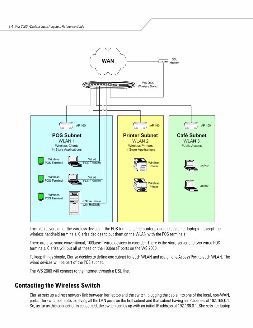
WS 2000 Wireless Switch System Reference Guide9-4
This plan covers all of the wireless devices—the POS terminals, the printers, and the customer laptops—except the wireless handheld terminals. Clarisa decides to put them on the WLAN with the POS terminals.
There are also some conventional, 100baseT wired devices to consider. There is the store server and two wired POS terminals. Clarisa will put all of these on the 100baseT ports on the WS 2000.
To keep things simple, Clarisa decides to define one subnet for each WLAN and assign one Access Port to each WLAN. The wired devices will be part of the POS subnet.
The WS 2000 will connect to the Internet through a DSL line.
Contacting the Wireless SwitchClarisa sets up a direct network link between her laptop and the switch, plugging the cable into one of the local, non-WAN, ports. The switch defaults to having all the LAN ports on the first subnet and that subnet having an IP address of 192.168.0.1. So, as far as this connection is concerned, the switch comes up with an initial IP address of 192.168.0.1. She sets her laptop
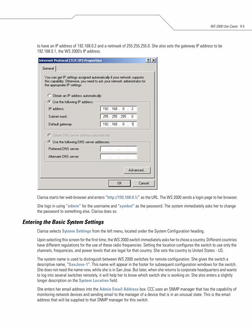
WS 2000 Use Cases 9-5
to have an IP address of 192.168.0.2 and a netmask of 255.255.255.0. She also sets the gateway IP address to be 192.168.0.1, the WS 2000’s IP address.
Clarisa starts her web browser and enters “http://192.168.0.1/” as the URL. The WS 2000 sends a login page to her browser.
She logs in using “admin” for the username and “symbol“ as the password. The system immediately asks her to change the password to something else. Clarisa does so.
Entering the Basic System SettingsClarisa selects System Settings from the left menu, located under the System Configuration heading.
Upon selecting this screen for the first time, the WS 2000 switch immediately asks her to chose a country. Different countries have different regulations for the use of these radio frequencies. Setting the location configures the switch to use only the channels, frequencies, and power levels that are legal for that country. She sets the country to United States - US.
The system name is used to distinguish between WS 2000 switches for remote configuration. She gives the switch a descriptive name, “SanJose-1”. This name will appear in the footer for subsequent configuration windows for the switch. She does not need the name now, while she is in San Jose. But later, when she returns to corporate headquarters and wants to log into several switches remotely, it will help her to know which switch she is working on. She also enters a slightly longer description on the System Location field.
She enters her email address into the Admin Email Address box. CCC uses an SNMP manager that has the capability of monitoring network devices and sending email to the manager of a device that is in an unusual state. This is the email address that will be supplied to that SNMP manager for this switch.
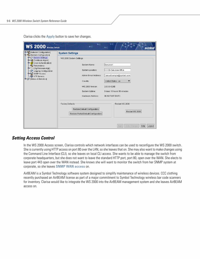
WS 2000 Wireless Switch System Reference Guide9-6
Clarisa clicks the Apply button to save her changes.
Setting Access ControlIn the WS 2000 Access screen, Clarisa controls which network interfaces can be used to reconfigure the WS 2000 switch. She is currently using HTTP access on port 80 over the LAN, so she leaves that on. She may also want to make changes using the Command Line Interface (CLI), so she leaves on local CLI access. She wants to be able to manage the switch from corporate headquarters, but she does not want to leave the standard HTTP port, port 80, open over the WAN. She elects to leave port 443 open over the WAN instead. She knows she will want to monitor the switch from her SNMP system at corporate, so she leaves SNMP WAN access on.
AirBEAM is a Symbol Technology software system designed to simplify maintenance of wireless devices. CCC clothing recently purchased an AirBEAM license as part of a major commitment to Symbol Technology wireless bar code scanners for inventory. Clarisa would like to integrate the WS 2000 into the AirBEAM management system and she leaves AirBEAM access on.
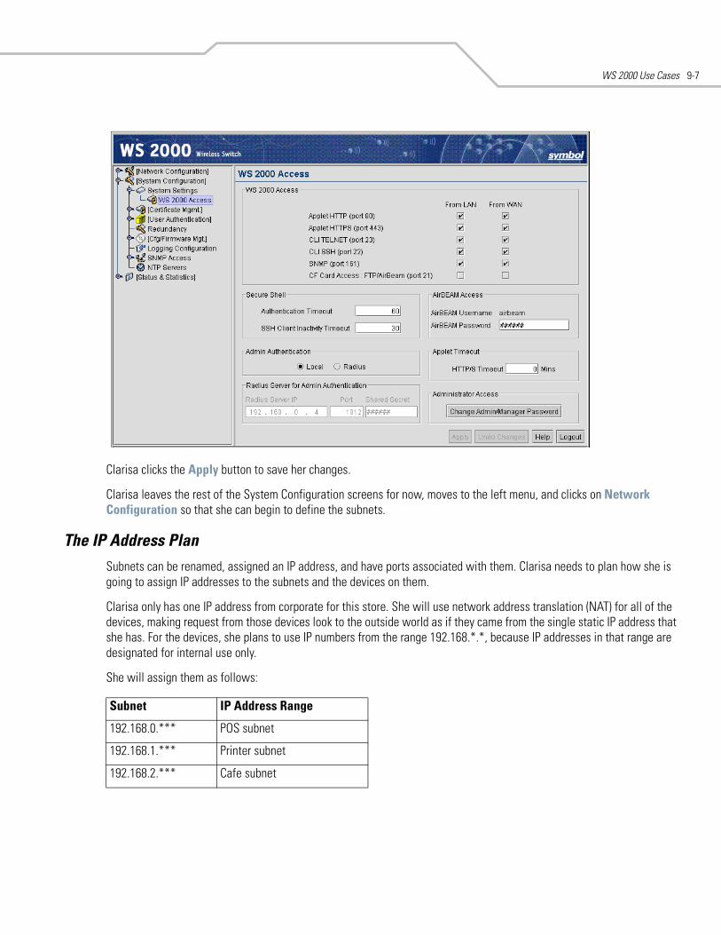
WS 2000 Use Cases 9-7
Clarisa clicks the Apply button to save her changes.
Clarisa leaves the rest of the System Configuration screens for now, moves to the left menu, and clicks on Network Configuration so that she can begin to define the subnets.
The IP Address PlanSubnets can be renamed, assigned an IP address, and have ports associated with them. Clarisa needs to plan how she is going to assign IP addresses to the subnets and the devices on them.
Clarisa only has one IP address from corporate for this store. She will use network address translation (NAT) for all of the devices, making request from those devices look to the outside world as if they came from the single static IP address that she has. For the devices, she plans to use IP numbers from the range 192.168.*.*, because IP addresses in that range are designated for internal use only.
She will assign them as follows:
Subnet IP Address Range
192.168.0.*** POS subnet
192.168.1.*** Printer subnet
192.168.2.*** Cafe subnet
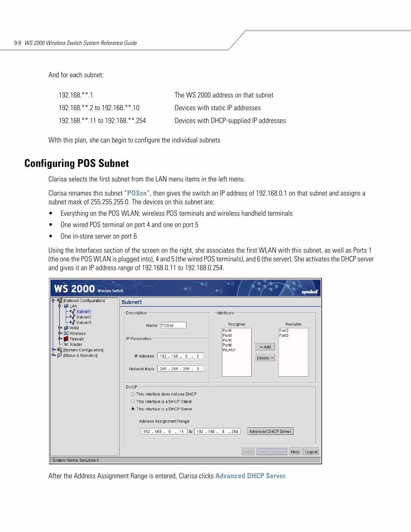
WS 2000 Wireless Switch System Reference Guide9-8
And for each subnet:
WIth this plan, she can begin to configure the individual subnets
Configuring POS SubnetClarisa selects the first subnet from the LAN menu items in the left menu.
Clarisa renames this subnet “POSsn”, then gives the switch an IP address of 192.168.0.1 on that subnet and assigns a subnet mask of 255.255.255.0. The devices on this subnet are:
• Everything on the POS WLAN: wireless POS terminals and wireless handheld terminals
• One wired POS terminal on port 4 and one on port 5
• One in-store server on port 6
Using the Interfaces section of the screen on the right, she associates the first WLAN with this subnet, as well as Ports 1 (the one the POS WLAN is plugged into), 4 and 5 (the wired POS terminals), and 6 (the server). She activates the DHCP server and gives it an IP address range of 192.168.0.11 to 192.168.0.254.
After the Address Assignment Range is entered, Clarisa clicks Advanced DHCP Server.
192.168.**.1 The WS 2000 address on that subnet
192.168.**.2 to 192.168.**.10 Devices with static IP addresses
192.168.**.11 to 192.168.**.254 Devices with DHCP-supplied IP addresses
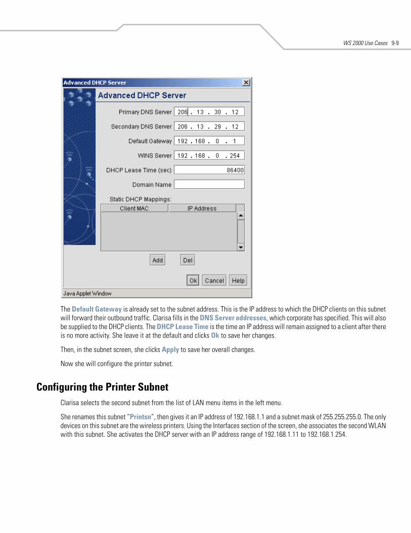
WS 2000 Use Cases 9-9
The Default Gateway is already set to the subnet address. This is the IP address to which the DHCP clients on this subnet will forward their outbound traffic. Clarisa fills in the DNS Server addresses, which corporate has specified. This will also be supplied to the DHCP clients. The DHCP Lease Time is the time an IP address will remain assigned to a client after there is no more activity. She leave it at the default and clicks Ok to save her changes.
Then, in the subnet screen, she clicks Apply to save her overall changes.
Now she will configure the printer subnet.
Configuring the Printer SubnetClarisa selects the second subnet from the list of LAN menu items in the left menu.
She renames this subnet “Printsn”, then gives it an IP address of 192.168.1.1 and a subnet mask of 255.255.255.0. The only devices on this subnet are the wireless printers. Using the Interfaces section of the screen, she associates the second WLAN with this subnet. She activates the DHCP server with an IP address range of 192.168.1.11 to 192.168.1.254.
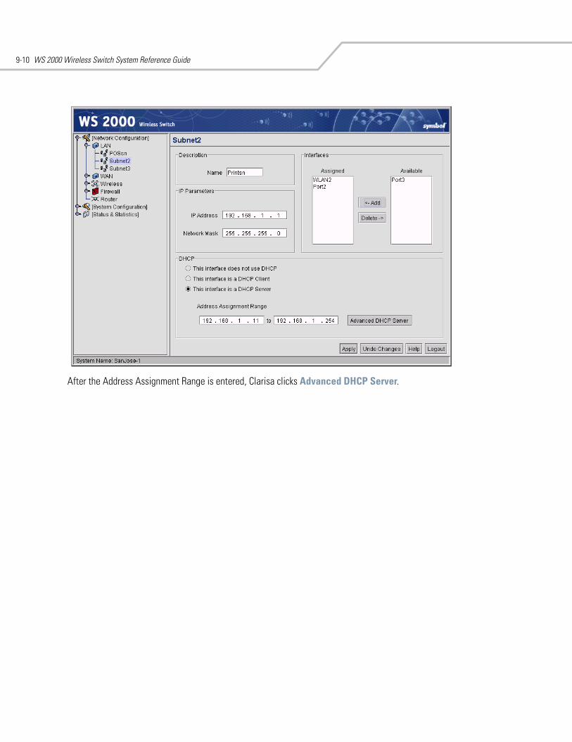
WS 2000 Wireless Switch System Reference Guide9-10
After the Address Assignment Range is entered, Clarisa clicks Advanced DHCP Server.
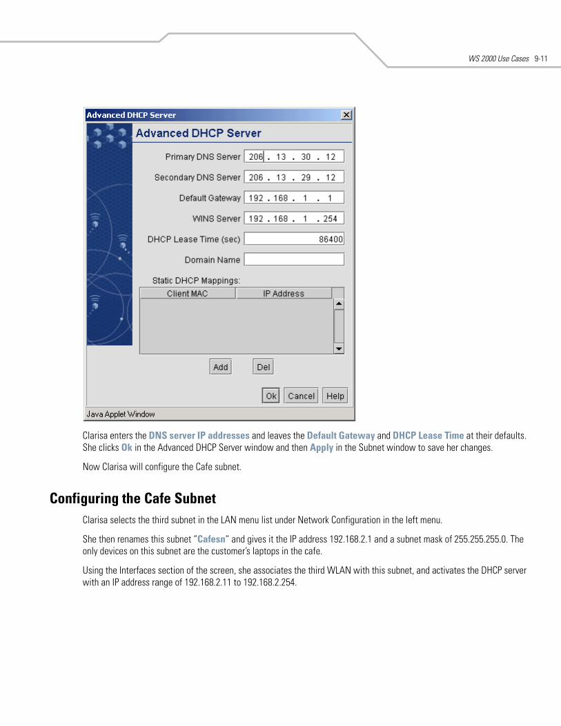
WS 2000 Use Cases 9-11
Clarisa enters the DNS server IP addresses and leaves the Default Gateway and DHCP Lease Time at their defaults. She clicks Ok in the Advanced DHCP Server window and then Apply in the Subnet window to save her changes.
Now Clarisa will configure the Cafe subnet.
Configuring the Cafe SubnetClarisa selects the third subnet in the LAN menu list under Network Configuration in the left menu.
She then renames this subnet “Cafesn“ and gives it the IP address 192.168.2.1 and a subnet mask of 255.255.255.0. The only devices on this subnet are the customer’s laptops in the cafe.
Using the Interfaces section of the screen, she associates the third WLAN with this subnet, and activates the DHCP server with an IP address range of 192.168.2.11 to 192.168.2.254.
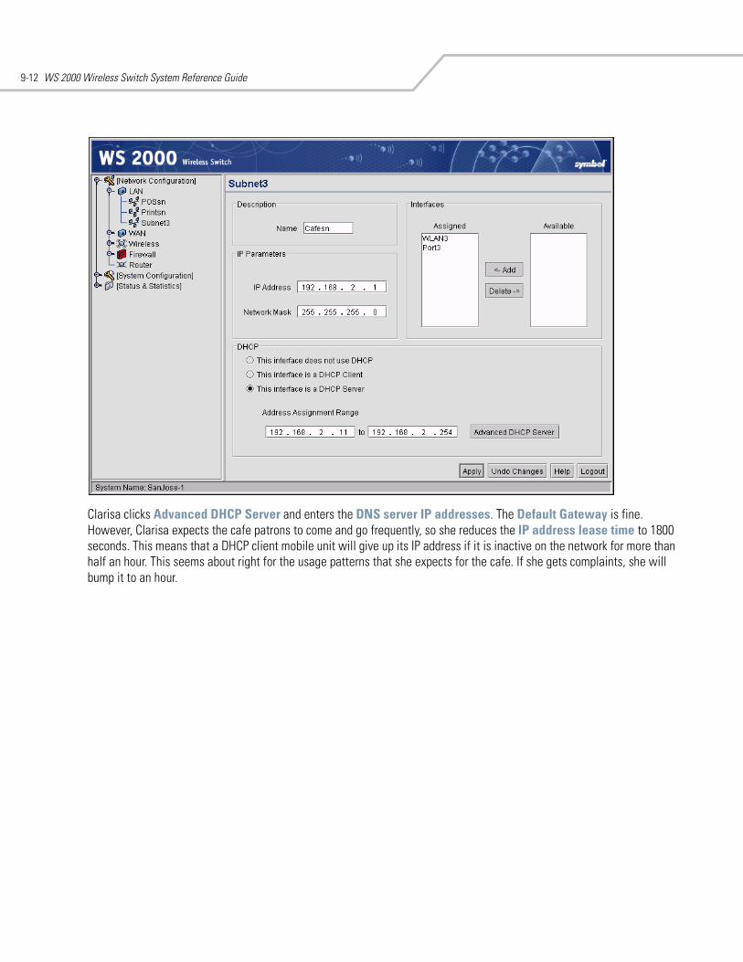
WS 2000 Wireless Switch System Reference Guide9-12
Clarisa clicks Advanced DHCP Server and enters the DNS server IP addresses. The Default Gateway is fine. However, Clarisa expects the cafe patrons to come and go frequently, so she reduces the IP address lease time to 1800 seconds. This means that a DHCP client mobile unit will give up its IP address if it is inactive on the network for more than half an hour. This seems about right for the usage patterns that she expects for the cafe. If she gets complaints, she will bump it to an hour.
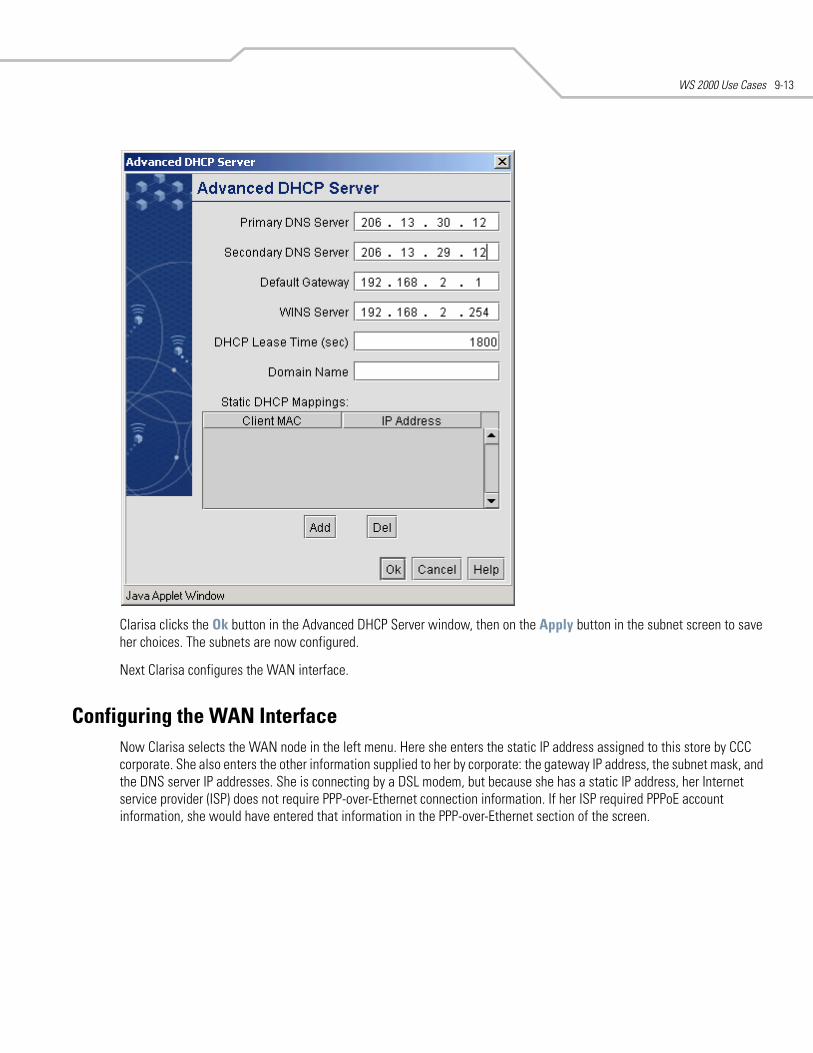
WS 2000 Use Cases 9-13
Clarisa clicks the Ok button in the Advanced DHCP Server window, then on the Apply button in the subnet screen to save her choices. The subnets are now configured.
Next Clarisa configures the WAN interface.
Configuring the WAN InterfaceNow Clarisa selects the WAN node in the left menu. Here she enters the static IP address assigned to this store by CCC corporate. She also enters the other information supplied to her by corporate: the gateway IP address, the subnet mask, and the DNS server IP addresses. She is connecting by a DSL modem, but because she has a static IP address, her Internet service provider (ISP) does not require PPP-over-Ethernet connection information. If her ISP required PPPoE account information, she would have entered that information in the PPP-over-Ethernet section of the screen.
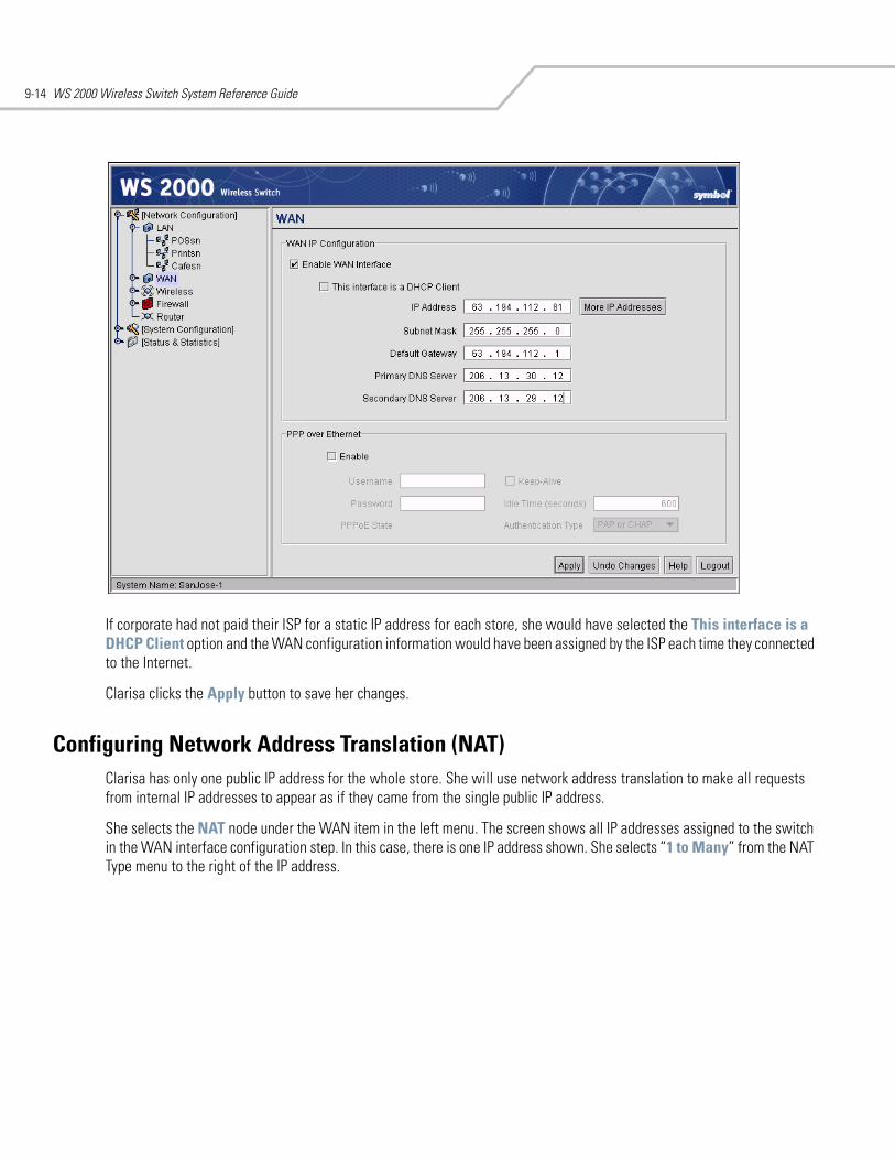
WS 2000 Wireless Switch System Reference Guide9-14
If corporate had not paid their ISP for a static IP address for each store, she would have selected the This interface is a DHCP Client option and the WAN configuration information would have been assigned by the ISP each time they connected to the Internet.
Clarisa clicks the Apply button to save her changes.
Configuring Network Address Translation (NAT)Clarisa has only one public IP address for the whole store. She will use network address translation to make all requests from internal IP addresses to appear as if they came from the single public IP address.
She selects the NAT node under the WAN item in the left menu. The screen shows all IP addresses assigned to the switch in the WAN interface configuration step. In this case, there is one IP address shown. She selects “1 to Many” from the NAT Type menu to the right of the IP address.
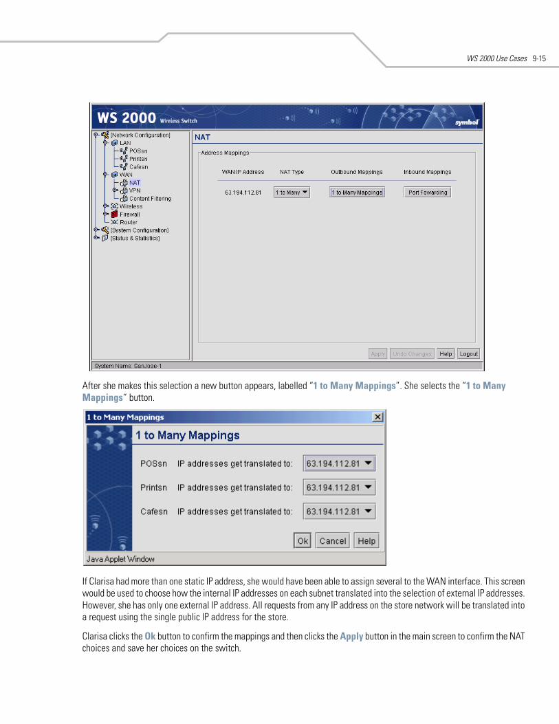
WS 2000 Use Cases 9-15
After she makes this selection a new button appears, labelled “1 to Many Mappings”. She selects the “1 to Many Mappings“ button.
If Clarisa had more than one static IP address, she would have been able to assign several to the WAN interface. This screen would be used to choose how the internal IP addresses on each subnet translated into the selection of external IP addresses. However, she has only one external IP address. All requests from any IP address on the store network will be translated into a request using the single public IP address for the store.
Clarisa clicks the Ok button to confirm the mappings and then clicks the Apply button in the main screen to confirm the NAT choices and save her choices on the switch.
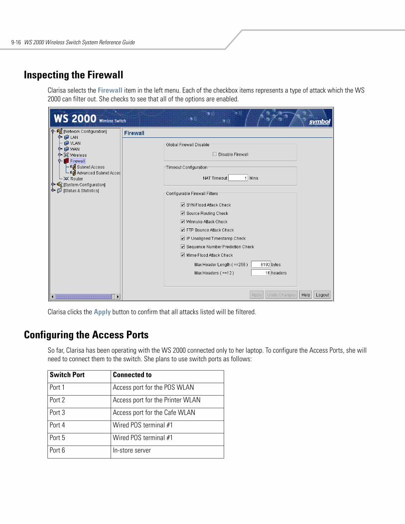
WS 2000 Wireless Switch System Reference Guide9-16
Inspecting the FirewallClarisa selects the Firewall item in the left menu. Each of the checkbox items represents a type of attack which the WS 2000 can filter out. She checks to see that all of the options are enabled.
Clarisa clicks the Apply button to confirm that all attacks listed will be filtered.
Configuring the Access PortsSo far, Clarisa has been operating with the WS 2000 connected only to her laptop. To configure the Access Ports, she will need to connect them to the switch. She plans to use switch ports as follows:
Switch Port Connected to
Port 1 Access port for the POS WLAN
Port 2 Access port for the Printer WLAN
Port 3 Access port for the Cafe WLAN
Port 4 Wired POS terminal #1
Port 5 Wired POS terminal #1
Port 6 In-store server
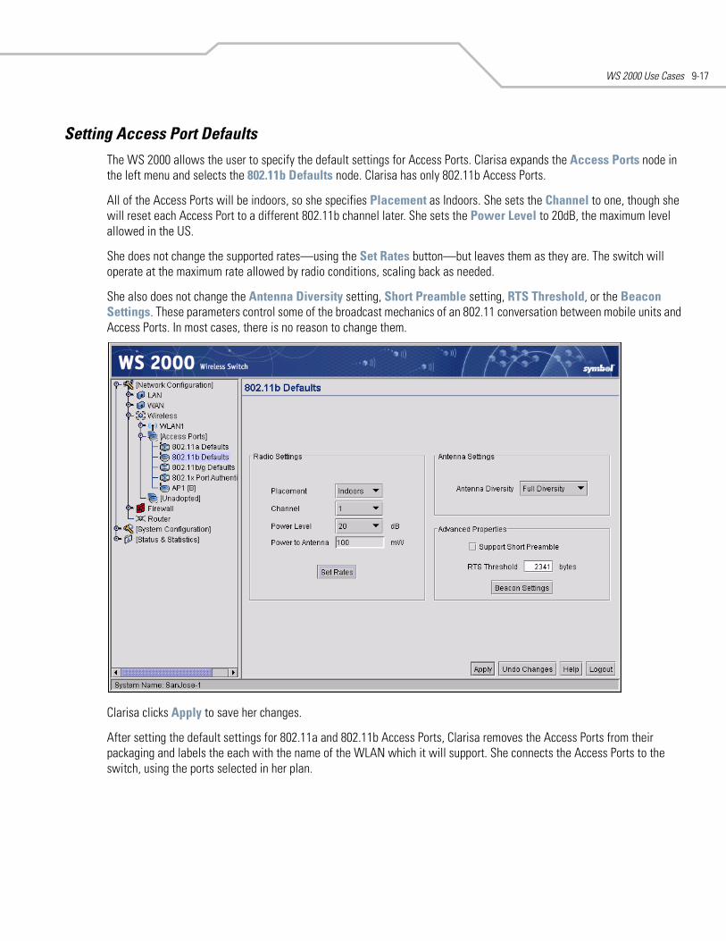
WS 2000 Use Cases 9-17
Setting Access Port DefaultsThe WS 2000 allows the user to specify the default settings for Access Ports. Clarisa expands the Access Ports node in the left menu and selects the 802.11b Defaults node. Clarisa has only 802.11b Access Ports.
All of the Access Ports will be indoors, so she specifies Placement as Indoors. She sets the Channel to one, though she will reset each Access Port to a different 802.11b channel later. She sets the Power Level to 20dB, the maximum level allowed in the US.
She does not change the supported rates—using the Set Rates button—but leaves them as they are. The switch will operate at the maximum rate allowed by radio conditions, scaling back as needed.
She also does not change the Antenna Diversity setting, Short Preamble setting, RTS Threshold, or the Beacon Settings. These parameters control some of the broadcast mechanics of an 802.11 conversation between mobile units and Access Ports. In most cases, there is no reason to change them.
Clarisa clicks Apply to save her changes.
After setting the default settings for 802.11a and 802.11b Access Ports, Clarisa removes the Access Ports from their packaging and labels the each with the name of the WLAN which it will support. She connects the Access Ports to the switch, using the ports selected in her plan.
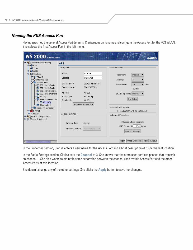
WS 2000 Wireless Switch System Reference Guide9-18
Naming the POS Access PortHaving specified the general Access Port defaults, Clarisa goes on to name and configure the Access Port for the POS WLAN. She selects the first Access Port in the left menu.
In the Properties section, Clarisa enters a new name for the Access Port and a brief description of its permanent location.
In the Radio Settings section, Clarisa sets the Channel to 3. She knows that the store uses cordless phones that transmit on channel 1. She also wants to maintain some separation between the channel used by this Access Port and the other Access Ports at this location.
She doesn’t change any of the other settings. She clicks the Apply button to save her changes.
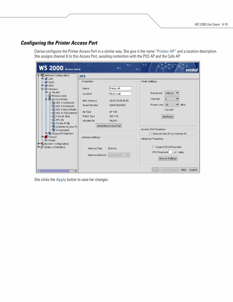
WS 2000 Use Cases 9-19
Configuring the Printer Access PortClarisa configures the Printer Access Port in a similar way. She give it the name “Printer AP“ and a location description. She assigns channel 6 to this Access Port, avoiding contention with the POS AP and the Cafe AP.
She clicks the Apply button to save her changes.
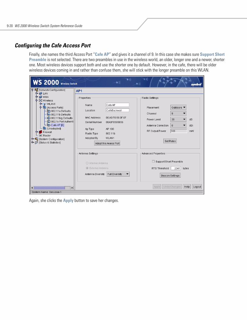
WS 2000 Wireless Switch System Reference Guide9-20
Configuring the Cafe Access PortFinally, she names the third Access Port “Cafe AP” and gives it a channel of 9. In this case she makes sure Support Short Preamble is not selected. There are two preambles in use in the wireless world, an older, longer one and a newer, shorter one. Most wireless devices support both and use the shorter one by default. However, in the cafe, there will be older wireless devices coming in and rather than confuse them, she will stick with the longer preamble on this WLAN.
Again, she clicks the Apply button to save her changes.
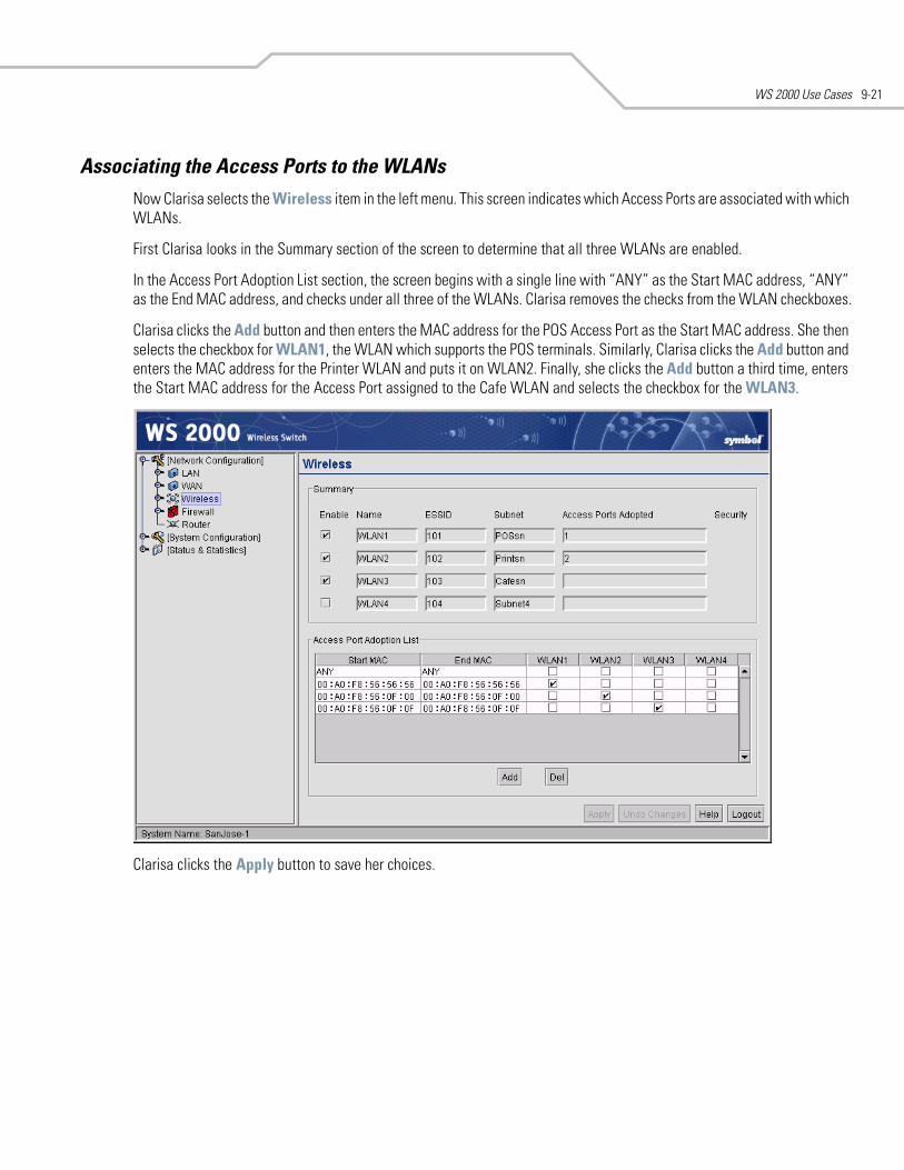
WS 2000 Use Cases 9-21
Associating the Access Ports to the WLANsNow Clarisa selects the Wireless item in the left menu. This screen indicates which Access Ports are associated with which WLANs.
First Clarisa looks in the Summary section of the screen to determine that all three WLANs are enabled.
In the Access Port Adoption List section, the screen begins with a single line with “ANY” as the Start MAC address, “ANY” as the End MAC address, and checks under all three of the WLANs. Clarisa removes the checks from the WLAN checkboxes.
Clarisa clicks the Add button and then enters the MAC address for the POS Access Port as the Start MAC address. She then selects the checkbox for WLAN1, the WLAN which supports the POS terminals. Similarly, Clarisa clicks the Add button and enters the MAC address for the Printer WLAN and puts it on WLAN2. Finally, she clicks the Add button a third time, enters the Start MAC address for the Access Port assigned to the Cafe WLAN and selects the checkbox for the WLAN3.
Clarisa clicks the Apply button to save her choices.
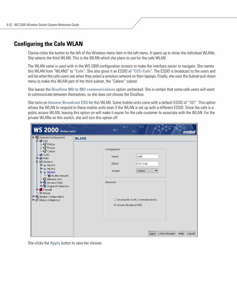
WS 2000 Wireless Switch System Reference Guide9-22
Configuring the Cafe WLANClarisa clicks the button to the left of the Wireless menu item in the left menu. It opens up to show the individual WLANs. She selects the third WLAN. This is the WLAN which she plans to use for the cafe WLAN.
The WLAN name is used with in the WS 2000 configuration screens to make the interface easier to navigate. She names this WLAN from “WLAN3” to “Cafe”. She also gives it an ESSID of “CCC-Cafe”. The ESSID is broadcast to the users and will be what the cafe users see when they select a wireless network on their laptops. Finally, she uses the Subnet pull-down menu to make this WLAN part of the third subnet, the “Cafesn” subnet.
She leaves the Disallow MU to MU communications option unchecked. She is certain that some cafe users will want to communicate between themselves, so she does not choose the Disallow.
She turns on Answer Broadcast ESS for this WLAN. Some mobile units come with a default ESSID of “101”. This option allows the WLAN to respond to these mobile units even if the WLAN is set up with a different ESSID. Since the cafe is a public access WLAN, leaving this option on will make it easier for the cafe customer to associate with the WLAN. For the private WLANs on this switch, she will turn this option off.
She clicks the Apply button to save her choices.
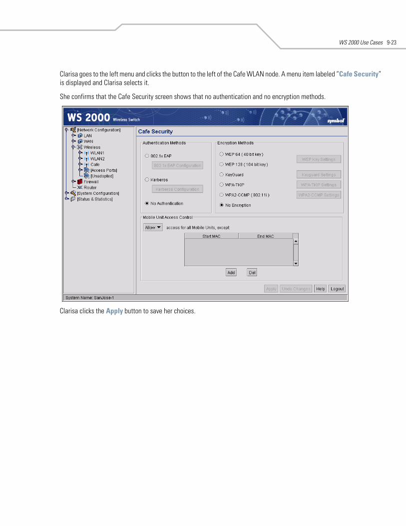
WS 2000 Use Cases 9-23
Clarisa goes to the left menu and clicks the button to the left of the Cafe WLAN node. A menu item labeled “Cafe Security” is displayed and Clarisa selects it.
She confirms that the Cafe Security screen shows that no authentication and no encryption methods.
Clarisa clicks the Apply button to save her choices.
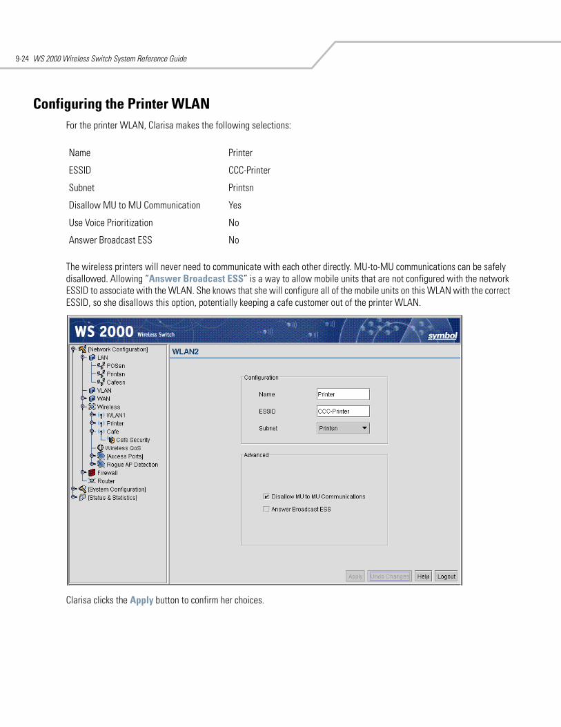
WS 2000 Wireless Switch System Reference Guide9-24
Configuring the Printer WLANFor the printer WLAN, Clarisa makes the following selections:
The wireless printers will never need to communicate with each other directly. MU-to-MU communications can be safely disallowed. Allowing “Answer Broadcast ESS” is a way to allow mobile units that are not configured with the network ESSID to associate with the WLAN. She knows that she will configure all of the mobile units on this WLAN with the correct ESSID, so she disallows this option, potentially keeping a cafe customer out of the printer WLAN.
Clarisa clicks the Apply button to confirm her choices.
Name Printer
ESSID CCC-Printer
Subnet Printsn
Disallow MU to MU Communication Yes
Use Voice Prioritization No
Answer Broadcast ESS No
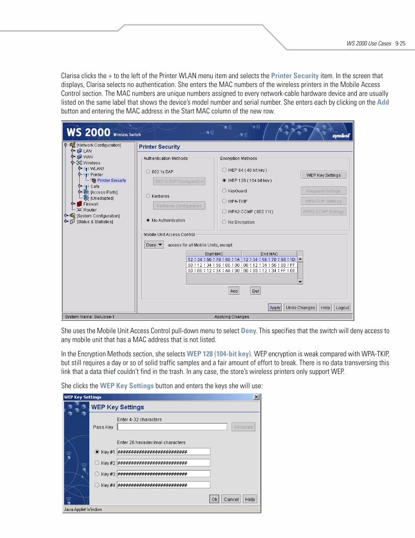
WS 2000 Use Cases 9-25
Clarisa clicks the + to the left of the Printer WLAN menu item and selects the Printer Security item. In the screen that displays, Clarisa selects no authentication. She enters the MAC numbers of the wireless printers in the Mobile Access Control section. The MAC numbers are unique numbers assigned to every network-cable hardware device and are usually listed on the same label that shows the device’s model number and serial number. She enters each by clicking on the Add button and entering the MAC address in the Start MAC column of the new row.
She uses the Mobile Unit Access Control pull-down menu to select Deny. This specifies that the switch will deny access to any mobile unit that has a MAC address that is not listed.
In the Encryption Methods section, she selects WEP 128 (104-bit key). WEP encryption is weak compared with WPA-TKIP, but still requires a day or so of solid traffic samples and a fair amount of effort to break. There is no data transversing this link that a data thief couldn’t find in the trash. In any case, the store’s wireless printers only support WEP.
She clicks the WEP Key Settings button and enters the keys she will use:
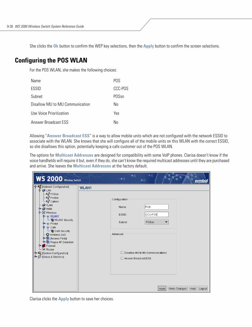
WS 2000 Wireless Switch System Reference Guide9-26
She clicks the Ok button to confirm the WEP key selections, then the Apply button to confirm the screen selections.
Configuring the POS WLANFor the POS WLAN, she makes the following choices:
Allowing “Answer Broadcast ESS” is a way to allow mobile units which are not configured with the network ESSID to associate with the WLAN. She knows that she will configure all of the mobile units on this WLAN with the correct ESSID, so she disallows this option, potentially keeping a cafe customer out of the POS WLAN.
The options for Multicast Addresses are designed for compatibility with some VoIP phones. Clarisa doesn’t know if the voice handhelds will require it but, even if they do, she can’t know the required multicast addresses until they are purchased and arrive. She leaves the Multicast Addresses at the factory default.
Clarisa clicks the Apply button to save her choices.
Name POS
ESSID CCC-POS
Subnet POSsn
Disallow MU to MU Communication No
Use Voice Prioritization Yes
Answer Broadcast ESS No
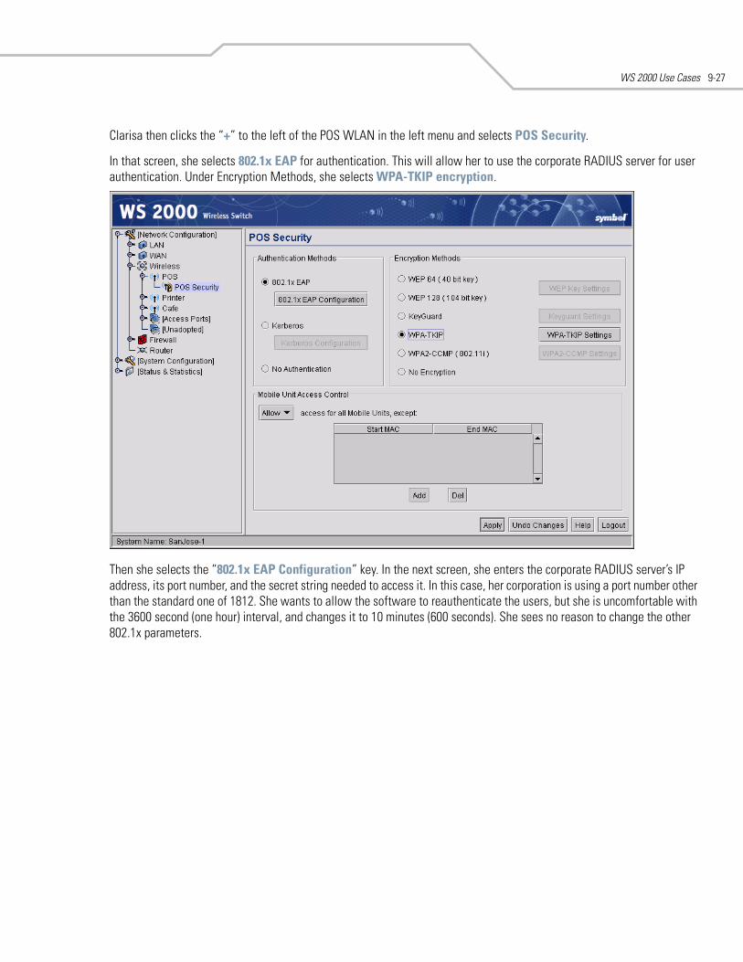
WS 2000 Use Cases 9-27
Clarisa then clicks the “+” to the left of the POS WLAN in the left menu and selects POS Security.
In that screen, she selects 802.1x EAP for authentication. This will allow her to use the corporate RADIUS server for user authentication. Under Encryption Methods, she selects WPA-TKIP encryption.
Then she selects the “802.1x EAP Configuration” key. In the next screen, she enters the corporate RADIUS server’s IP address, its port number, and the secret string needed to access it. In this case, her corporation is using a port number other than the standard one of 1812. She wants to allow the software to reauthenticate the users, but she is uncomfortable with the 3600 second (one hour) interval, and changes it to 10 minutes (600 seconds). She sees no reason to change the other 802.1x parameters.
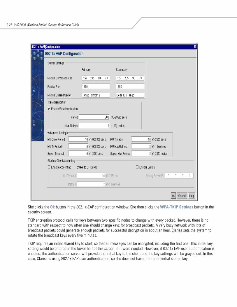
WS 2000 Wireless Switch System Reference Guide9-28
She clicks the Ok button in the 802.1x-EAP configuration window. She then clicks the WPA-TKIP Settings button in the security screen.
TKIP encryption protocol calls for keys between two specific nodes to change with every packet. However, there is no standard with respect to how often one should change keys for broadcast packets. A very busy network with lots of broadcast packets could generate enough packets for successful decryption in about an hour. Clarisa sets the system to rotate the broadcast keys every five minutes.
TKIP requires an initial shared key to start, so that all messages can be encrypted, including the first one. This initial key setting would be entered in the lower half of this screen, if it were needed. However, if 802.1x EAP user authentication is enabled, the authentication server will provide the initial key to the client and the key settings will be grayed out. In this case, Clarisa is using 802.1x EAP user authentication, so she does not have it enter an initial shared key.
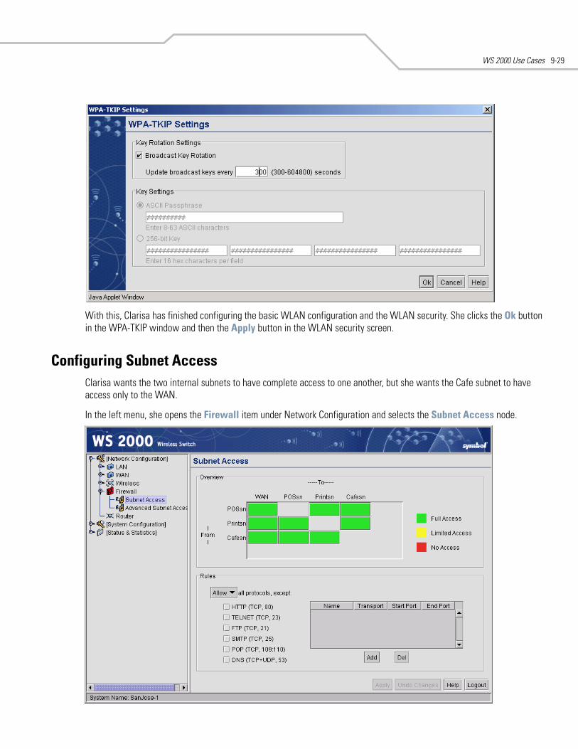
WS 2000 Use Cases 9-29
With this, Clarisa has finished configuring the basic WLAN configuration and the WLAN security. She clicks the Ok button in the WPA-TKIP window and then the Apply button in the WLAN security screen.
Configuring Subnet AccessClarisa wants the two internal subnets to have complete access to one another, but she wants the Cafe subnet to have access only to the WAN.
In the left menu, she opens the Firewall item under Network Configuration and selects the Subnet Access node.
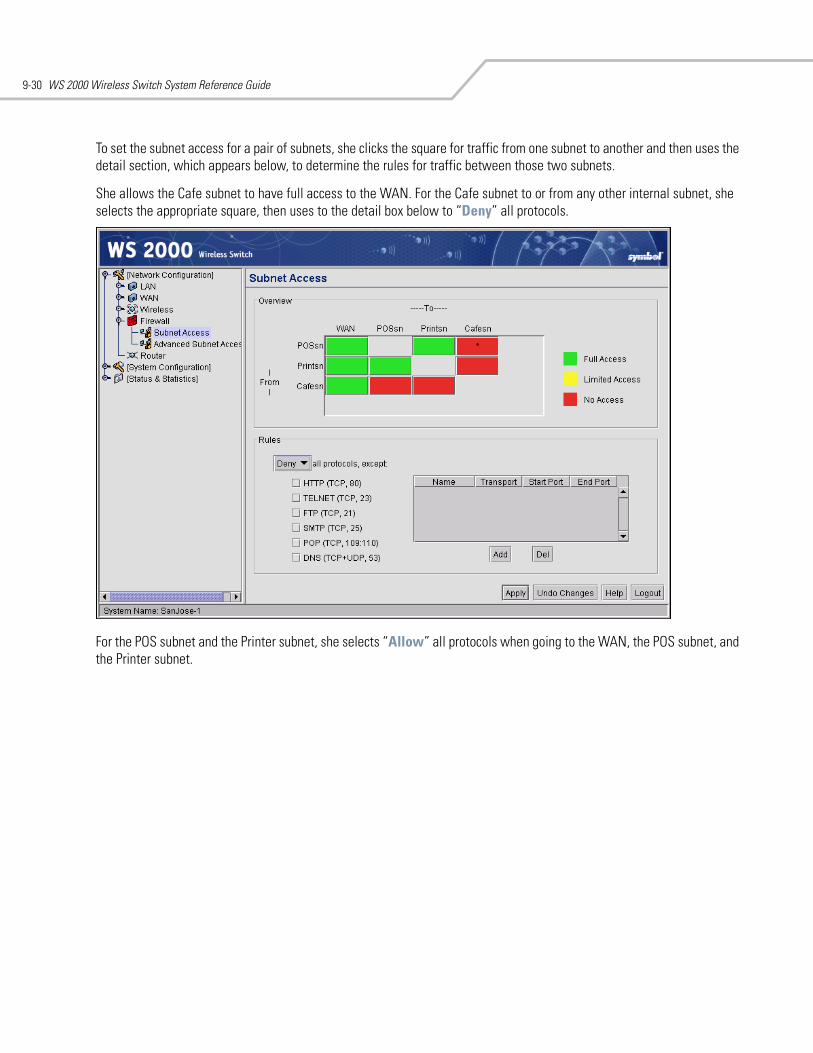
WS 2000 Wireless Switch System Reference Guide9-30
To set the subnet access for a pair of subnets, she clicks the square for traffic from one subnet to another and then uses the detail section, which appears below, to determine the rules for traffic between those two subnets.
She allows the Cafe subnet to have full access to the WAN. For the Cafe subnet to or from any other internal subnet, she selects the appropriate square, then uses to the detail box below to “Deny” all protocols.
For the POS subnet and the Printer subnet, she selects “Allow” all protocols when going to the WAN, the POS subnet, and the Printer subnet.
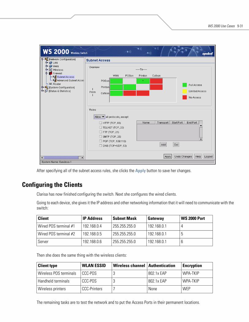
WS 2000 Use Cases 9-31
After specifying all of the subnet access rules, she clicks the Apply button to save her changes.
Configuring the ClientsClarisa has now finished configuring the switch. Next she configures the wired clients.
Going to each device, she gives it the IP address and other networking information that it will need to communicate with the switch:
Then she does the same thing with the wireless clients:
The remaining tasks are to test the network and to put the Access Ports in their permanent locations.
Client IP Address Subnet Mask Gateway WS 2000 Port
Wired POS terminal #1 192.168.0.4 255.255.255.0 192.168.0.1 4
Wired POS terminal #2 192.168.0.5 255.255.255.0 192.168.0.1 5
Server 192.168.0.6 255.255.255.0 192.168.0.1 6
Client type WLAN ESSID Wireless channel Authentication Encryption
Wireless POS terminals CCC-POS 3 802.1x EAP WPA-TKIP
Handheld terminals CCC-POS 3 802.1x EAP WPA-TKIP
Wireless printers CCC-Printers 7 None WEP
WS 2000 Wireless Switch System Reference Guide9-32
Testing ConnectionsClarisa powers up several sample devices and tests them, to be sure that they work as configured. She tests whether the devices can connect to the wireless switch and whether they can connect to devices on other subnets.
After she is confident that everything is working, she moves the Access Ports to their permanent locations. She connects the WS 2000 to the DSL modem. Finally, she tests the connection from each subnet to the WAN.
The store network is now complete.
WS 2000 Use Cases 9-33
Field Office Use Case
A Field Office Example
Background
Leo is the network administrator, system administrator, and IT professional for a field office with 60 employees. The users include sales people, sales engineers, office administration and customer support people. All of the sales personnel have laptops and many of them have personal digital assistants (PDAs).
The office is connected to the Internet and to corporate through a frame relay link. Between the office network and the frame relay, there is a router and a virtual private network (VPN) appliance. All traffic to corporate is encrypted by the VPN appliance. Traffic to other addresses passes straight through.
Leo installed a wireless access point about six months ago and quickly found that many employees preferred to use it. However, the throughput of the lone unit was not enough to service 40 or so users and coverage was weak in many areas of the building. In addition, Leo was doing user authentication by maintaining a list of permissible user MAC addresses on the access point. This required modifications to the list once or twice a week. Recently, when a laptop was stolen, Leo could not determine which MAC address to remove from the list for several hours. He concluded that a better method of user authentication was needed. Also, the data encryption on the old access point was WEP and WEP encryption can be broken with several hours of data encrypted with the same key. Leo changes the key every week, but some users complain when last week’s key does not work anymore.
Leo has decided to upgrade to a WS 2000 wireless switch. He will have four Access Ports, one in the administration office area, one in the sales office area, one in the sales engineering area, and one in the engineers’ demonstration room. Throughput and coverage will increase significantly. Leo will convert to 802.1x/EAP-TTLS user authentication through the corporate RADIUS server and convert to WPA2 encryption, improving security considerably and reducing maintenance significantly.
Leo’s company is also growing. Corporate has rented an expansion office for engineering in another part of the same building. Leo needs to establish secure communication with from the engineering subnet to this expansion office. The other office will also have a WS 2000, so Leo will establish a direct VPN link to that WS 2000 and use the VPN as the secure communication link.
The following links show the tasks that Leo will carry out to complete the wireless upgrade.
The PlanEach WS 2000 WLAN has exactly one security policy, where a security policy is defined as a user authentication method and a data encryption method. Because each WLAN can have one and only one security policy, WLAN configuration is usually defined by the security needs of the installation. If two groups of users require different security policies, then they must associate to the WS 2000 through different WLANs. See the retail case study for an example of an installation where different security needs drive the need for separate WLANs.
In this situation, all of Leo’s users will use the same security system: 802.1x/EAP-TTLS user authentication and WPA data encryption. Leo can set up the WLANs in any way that is convenient.
Corporate has given Leo three static IP addresses for the wireless network. He will configure the WS 2000 as a DHCP server giving out internal-use-only IP addresses and use network address translation (NAT) in the switch to convert the outward-bound traffic to one of the static IP addresses.
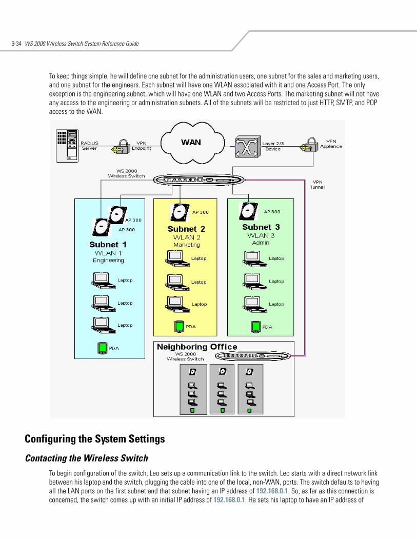
WS 2000 Wireless Switch System Reference Guide9-34
To keep things simple, he will define one subnet for the administration users, one subnet for the sales and marketing users, and one subnet for the engineers. Each subnet will have one WLAN associated with it and one Access Port. The only exception is the engineering subnet, which will have one WLAN and two Access Ports. The marketing subnet will not have any access to the engineering or administration subnets. All of the subnets will be restricted to just HTTP, SMTP, and POP access to the WAN.
Configuring the System Settings
Contacting the Wireless SwitchTo begin configuration of the switch, Leo sets up a communication link to the switch. Leo starts with a direct network link between his laptop and the switch, plugging the cable into one of the local, non-WAN, ports. The switch defaults to having all the LAN ports on the first subnet and that subnet having an IP address of 192.168.0.1. So, as far as this connection is concerned, the switch comes up with an initial IP address of 192.168.0.1. He sets his laptop to have an IP address of
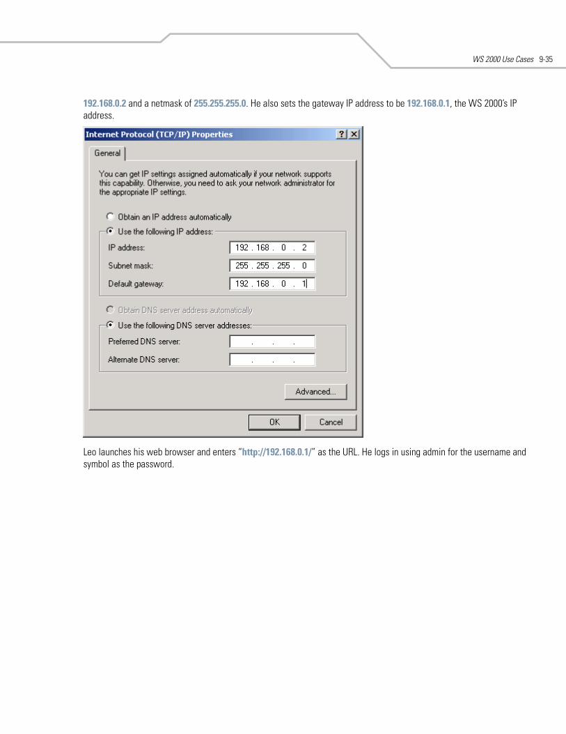
WS 2000 Use Cases 9-35
192.168.0.2 and a netmask of 255.255.255.0. He also sets the gateway IP address to be 192.168.0.1, the WS 2000’s IP address.
Leo launches his web browser and enters “http://192.168.0.1/” as the URL. He logs in using admin for the username and symbol as the password.
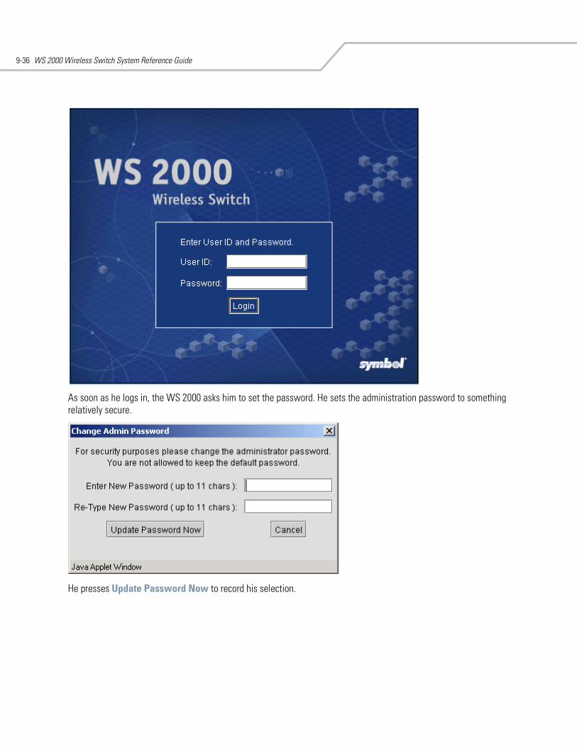
WS 2000 Wireless Switch System Reference Guide9-36
As soon as he logs in, the WS 2000 asks him to set the password. He sets the administration password to something relatively secure.
He presses Update Password Now to record his selection.
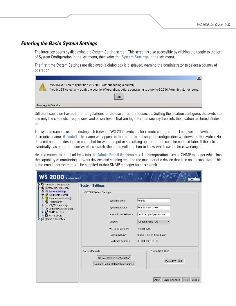
WS 2000 Use Cases 9-37
Entering the Basic System SettingsThe interface opens by displaying the System Setting screen. This screen is also accessible by clicking the toggle to the left of System Configuration in the left menu, then selecting System Settings in the left menu.
The first time System Settings are displayed, a dialog box is displayed, warning the administrator to select a country of operation.
Different countries have different regulations for the use of radio frequencies. Setting the location configures the switch to use only the channels, frequencies, and power levels that are legal for that country. Leo sets the location to United States - us.
The system name is used to distinguish between WS 2000 switches for remote configuration. Leo gives the switch a descriptive name, Atlanta1. This name will appear in the footer for subsequent configuration windows for the switch. He does not need the descriptive name, but he wants to put in something appropriate in case he needs it later. If the office eventually has more than one wireless switch, the name will help him to know which switch he is working on.
He also enters his email address into the Admin Email Address box. Leo’s corporation uses an SNMP manager which has the capability of monitoring network devices and sending email to the manager of a device that is in an unusual state. This is the email address that will be supplied to that SNMP manager for this switch.
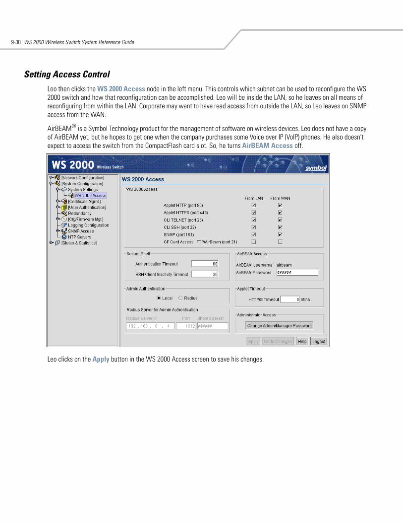
WS 2000 Wireless Switch System Reference Guide9-38
Setting Access ControlLeo then clicks the WS 2000 Access node in the left menu. This controls which subnet can be used to reconfigure the WS 2000 switch and how that reconfiguration can be accomplished. Leo will be inside the LAN, so he leaves on all means of reconfiguring from within the LAN. Corporate may want to have read access from outside the LAN, so Leo leaves on SNMP access from the WAN.
AirBEAM® is a Symbol Technology product for the management of software on wireless devices. Leo does not have a copy of AirBEAM yet, but he hopes to get one when the company purchases some Voice over IP (VoIP) phones. He also doesn’t expect to access the switch from the CompactFlash card slot. So, he turns AirBEAM Access off.
Leo clicks on the Apply button in the WS 2000 Access screen to save his changes.
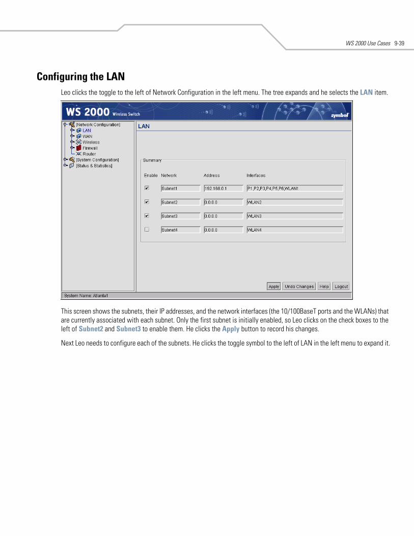
WS 2000 Use Cases 9-39
Configuring the LANLeo clicks the toggle to the left of Network Configuration in the left menu. The tree expands and he selects the LAN item.
This screen shows the subnets, their IP addresses, and the network interfaces (the 10/100BaseT ports and the WLANs) that are currently associated with each subnet. Only the first subnet is initially enabled, so Leo clicks on the check boxes to the left of Subnet2 and Subnet3 to enable them. He clicks the Apply button to record his changes.
Next Leo needs to configure each of the subnets. He clicks the toggle symbol to the left of LAN in the left menu to expand it.
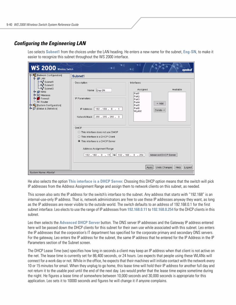
WS 2000 Wireless Switch System Reference Guide9-40
Configuring the Engineering LANLeo selects Subnet1 from the choices under the LAN heading. He enters a new name for the subnet, Eng-SN, to make it easier to recognize this subnet throughout the WS 2000 interface.
He also selects the option This interface is a DHCP Server. Choosing this DHCP option means that the switch will pick IP addresses from the Address Assignment Range and assign them to network clients on this subnet, as needed.
This screen also sets the IP address for the switch’s interface to the subnet. Any address that starts with “192.168” is an internal-use-only IP address. That is, network administrators are free to use these IP addresses anyway they want, as long as the IP addresses are never visible to the outside world. The switch defaults to an address of 192.168.0.1 for the first subnet interface. Leo elects to use the range of IP addresses from 192.168.0.11 to 192.168.0.254 for the DHCP clients in this subnet.
Leo then selects the Advanced DHCP Server button. The DNS server IP addresses and the Gateway IP address entered here will be passed down the DHCP clients for this subnet for their own use while associated with this subnet. Leo enters the IP addresses that the corporation’s IT department has specified for the corporate primary and secondary DNS servers. For the gateway, Leo enters the IP address for the subnet, the same IP address that he entered for the IP Address in the IP Parameters section of the Subnet screen.
The DHCP Lease Time (sec) specifies how long in seconds a client may keep an IP address when that client is not active on the net. The lease time is currently set for 86,400 seconds, or 24 hours. Leo expects that people using these WLANs will connect for a work day or not. While in the office, he expects that their machines will initiate contact with the network every 10 or 15 minutes for email. When they unplug to go home, this lease time will hold their IP address for another full day and not return it to the usable pool until the end of the next day. Leo would prefer that the lease time expire sometime during the night. He figures a lease time of somewhere between 10,000 seconds and 30,000 seconds is appropriate for this application. Leo sets it to 10000 seconds and figures he will change it if anyone complains.
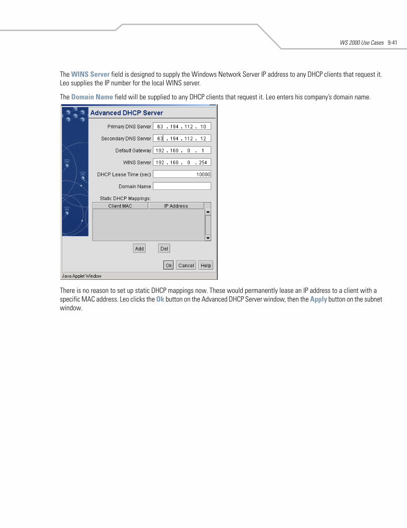
WS 2000 Use Cases 9-41
The WINS Server field is designed to supply the Windows Network Server IP address to any DHCP clients that request it. Leo supplies the IP number for the local WINS server.
The Domain Name field will be supplied to any DHCP clients that request it. Leo enters his company’s domain name.
There is no reason to set up static DHCP mappings now. These would permanently lease an IP address to a client with a specific MAC address. Leo clicks the Ok button on the Advanced DHCP Server window, then the Apply button on the subnet window.
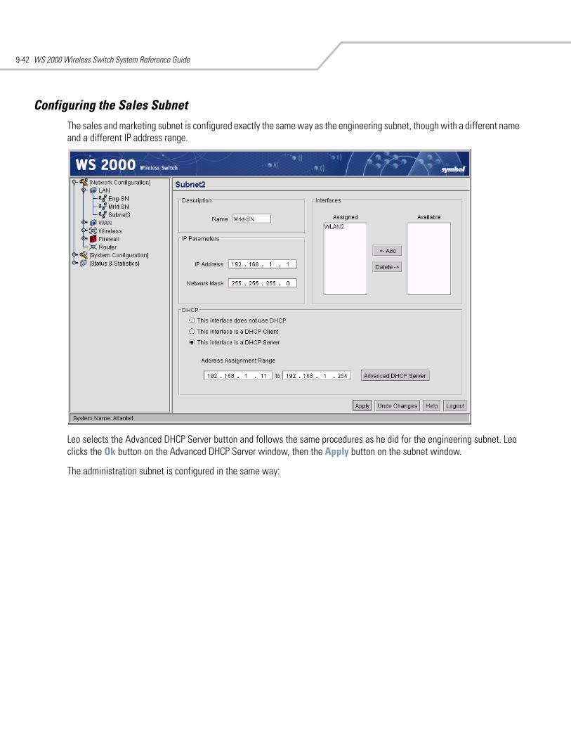
WS 2000 Wireless Switch System Reference Guide9-42
Configuring the Sales SubnetThe sales and marketing subnet is configured exactly the same way as the engineering subnet, though with a different name and a different IP address range.
Leo selects the Advanced DHCP Server button and follows the same procedures as he did for the engineering subnet. Leo clicks the Ok button on the Advanced DHCP Server window, then the Apply button on the subnet window.
The administration subnet is configured in the same way:
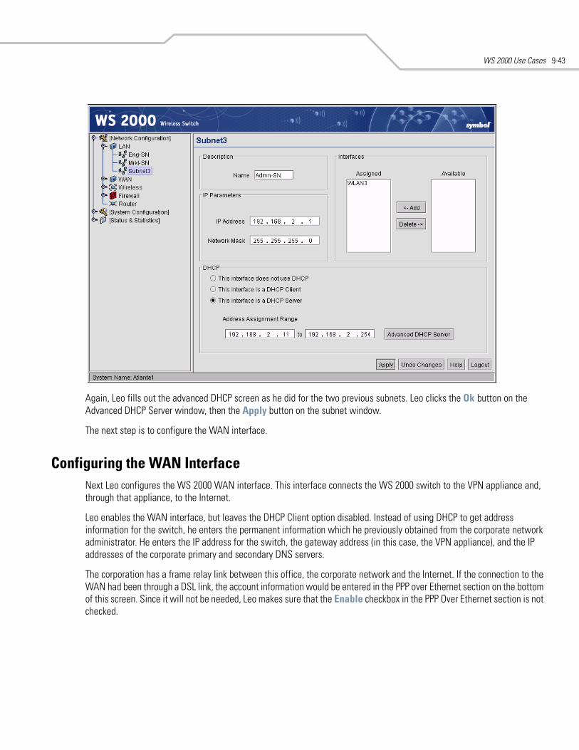
WS 2000 Use Cases 9-43
Again, Leo fills out the advanced DHCP screen as he did for the two previous subnets. Leo clicks the Ok button on the Advanced DHCP Server window, then the Apply button on the subnet window.
The next step is to configure the WAN interface.
Configuring the WAN InterfaceNext Leo configures the WS 2000 WAN interface. This interface connects the WS 2000 switch to the VPN appliance and, through that appliance, to the Internet.
Leo enables the WAN interface, but leaves the DHCP Client option disabled. Instead of using DHCP to get address information for the switch, he enters the permanent information which he previously obtained from the corporate network administrator. He enters the IP address for the switch, the gateway address (in this case, the VPN appliance), and the IP addresses of the corporate primary and secondary DNS servers.
The corporation has a frame relay link between this office, the corporate network and the Internet. If the connection to the WAN had been through a DSL link, the account information would be entered in the PPP over Ethernet section on the bottom of this screen. Since it will not be needed, Leo makes sure that the Enable checkbox in the PPP Over Ethernet section is not checked.
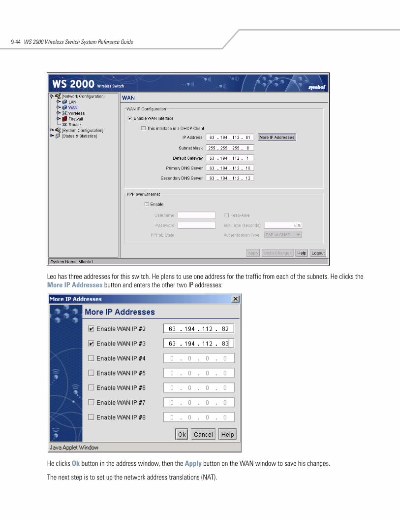
WS 2000 Wireless Switch System Reference Guide9-44
Leo has three addresses for this switch. He plans to use one address for the traffic from each of the subnets. He clicks the More IP Addresses button and enters the other two IP addresses:
He clicks Ok button in the address window, then the Apply button on the WAN window to save his changes.
The next step is to set up the network address translations (NAT).
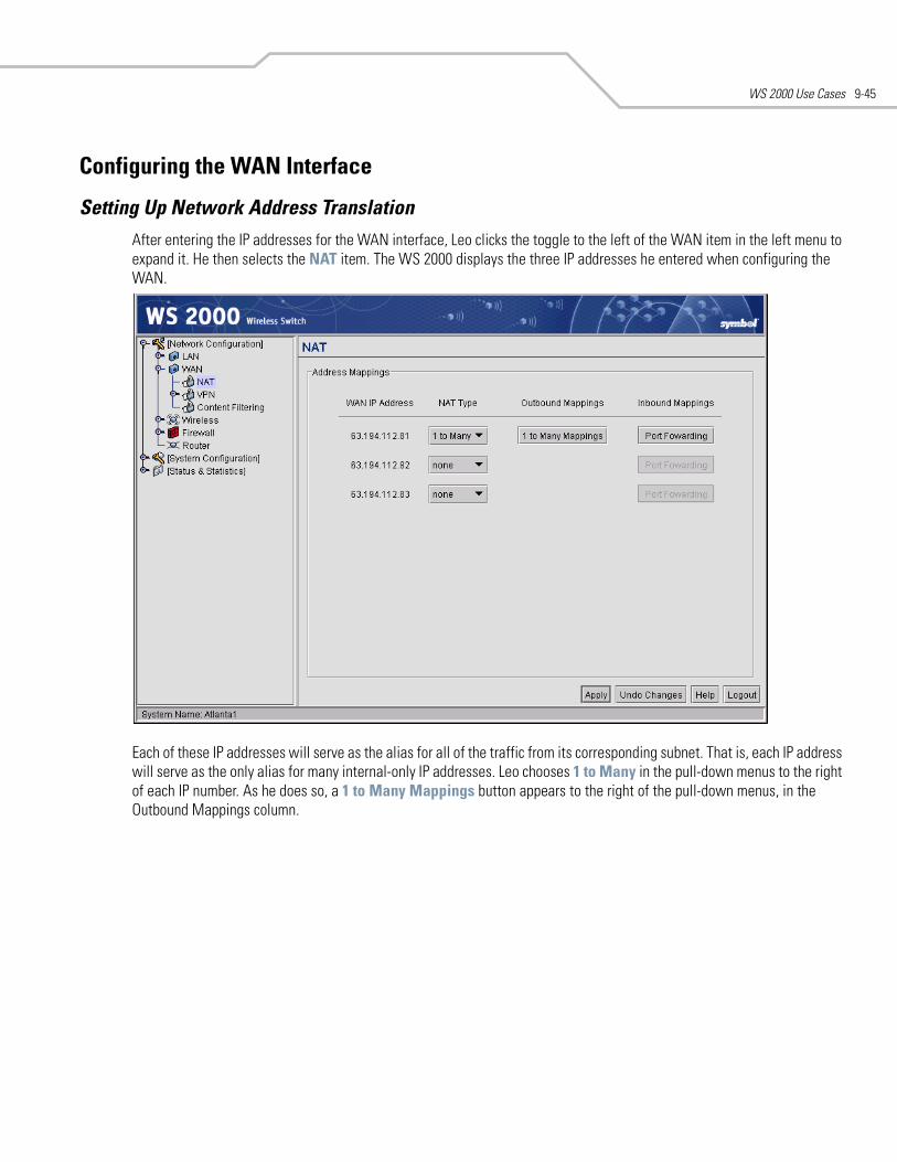
WS 2000 Use Cases 9-45
Configuring the WAN Interface
Setting Up Network Address Translation After entering the IP addresses for the WAN interface, Leo clicks the toggle to the left of the WAN item in the left menu to expand it. He then selects the NAT item. The WS 2000 displays the three IP addresses he entered when configuring the WAN.
Each of these IP addresses will serve as the alias for all of the traffic from its corresponding subnet. That is, each IP address will serve as the only alias for many internal-only IP addresses. Leo chooses 1 to Many in the pull-down menus to the right of each IP number. As he does so, a 1 to Many Mappings button appears to the right of the pull-down menus, in the Outbound Mappings column.
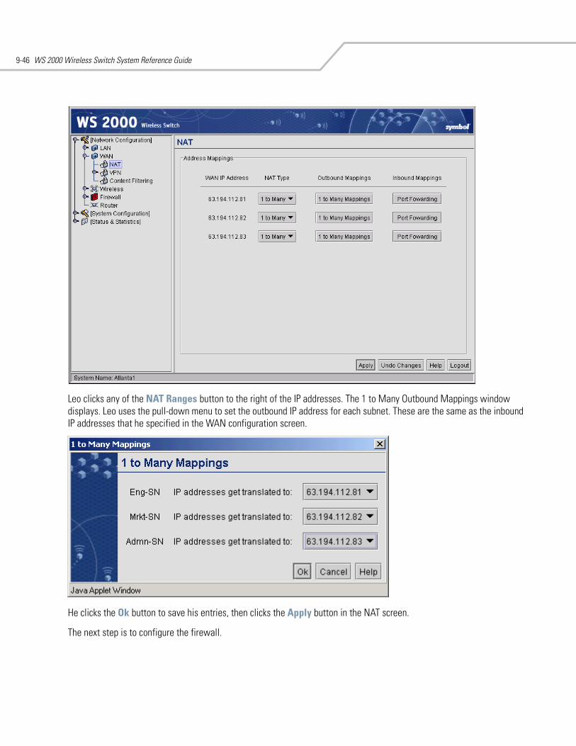
WS 2000 Wireless Switch System Reference Guide9-46
Leo clicks any of the NAT Ranges button to the right of the IP addresses. The 1 to Many Outbound Mappings window displays. Leo uses the pull-down menu to set the outbound IP address for each subnet. These are the same as the inbound IP addresses that he specified in the WAN configuration screen.
He clicks the Ok button to save his entries, then clicks the Apply button in the NAT screen.
The next step is to configure the firewall.
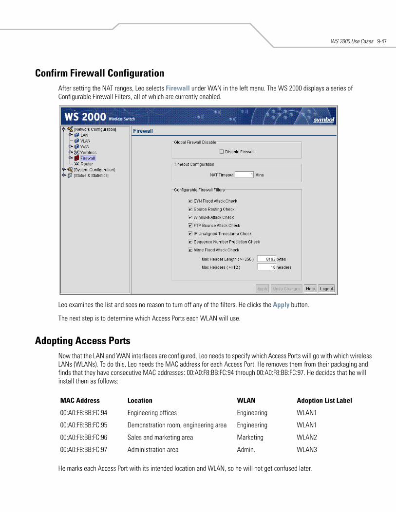
WS 2000 Use Cases 9-47
Confirm Firewall ConfigurationAfter setting the NAT ranges, Leo selects Firewall under WAN in the left menu. The WS 2000 displays a series of Configurable Firewall Filters, all of which are currently enabled.
Leo examines the list and sees no reason to turn off any of the filters. He clicks the Apply button.
The next step is to determine which Access Ports each WLAN will use.
Adopting Access PortsNow that the LAN and WAN interfaces are configured, Leo needs to specify which Access Ports will go with which wireless LANs (WLANs). To do this, Leo needs the MAC address for each Access Port. He removes them from their packaging and finds that they have consecutive MAC addresses: 00:A0:F8:BB:FC:94 through 00:A0:F8:BB:FC:97. He decides that he will install them as follows:
He marks each Access Port with its intended location and WLAN, so he will not get confused later.
MAC Address Location WLAN Adoption List Label
00:A0:F8:BB:FC:94 Engineering offices Engineering WLAN1
00:A0:F8:BB:FC:95 Demonstration room, engineering area Engineering WLAN1
00:A0:F8:BB:FC:96 Sales and marketing area Marketing WLAN2
00:A0:F8:BB:FC:97 Administration area Admin. WLAN3
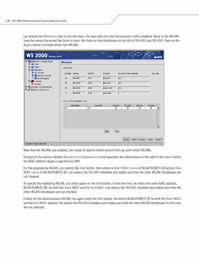
WS 2000 Wireless Switch System Reference Guide9-48
Leo selects the Wireless item in the left menu. He sees that only the first wireless LAN is enabled. None of the WLANs have the names he would like them to have. He clicks on the checkboxes to the left of WLAN2 and WLAN3, then on the Apply button to enable these two WLANs.
Now that the WLANs are enabled, Leo needs to specify which Access Ports go with which WLANs.
He goes to the section labeled Access Port Adoption List and deselects the check boxes to the right of the row in which the MAC address range is specified as ANY.
For the engineering WLAN, Leo selects the Add button, then enters a Start MAC value of 00:A0:F8:BB:FC:94 and an End MAC value of 00:A0:F8:BB:FC:95. Leo selects the WLAN1 checkbox and makes sure that the other WLAN checkboxes are not checked.
To specify the marketing WLAN, Leo clicks again on the Add button. In the new line, he enters the same MAC address, 00:A0:F8:BB:FC:96, for both the Start MAC and the End MAC. Leo selects the WLAN2 checkbox and makes sure that the other WLAN checkboxes are not checked.
Finally, for the administration WLAN, Leo again clicks the Add button. He enters 00:A0:F8:BB:FC:97 as both the Start MAC and the End MAC address. He selects the WLAN3 checkbox and makes sure that the other WLAN checkboxes for that row are not selected.
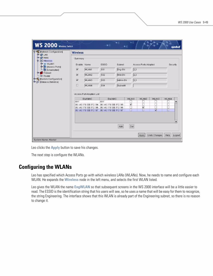
WS 2000 Use Cases 9-49
Leo clicks the Apply button to save his changes.
The next step is configure the WLANs.
Configuring the WLANsLeo has specified which Access Ports go with which wireless LANs (WLANs). Now, he needs to name and configure each WLAN. He expands the Wireless node in the left menu, and selects the first WLAN listed.
Leo gives the WLAN the name EngWLAN so that subsequent screens in the WS 2000 interface will be a little easier to read. The ESSID is the identification string that his users will see, so he uses a name that will be easy for them to recognize, the string Engineering. The interface shows that this WLAN is already part of the Engineering subnet, so there is no reason to change it.
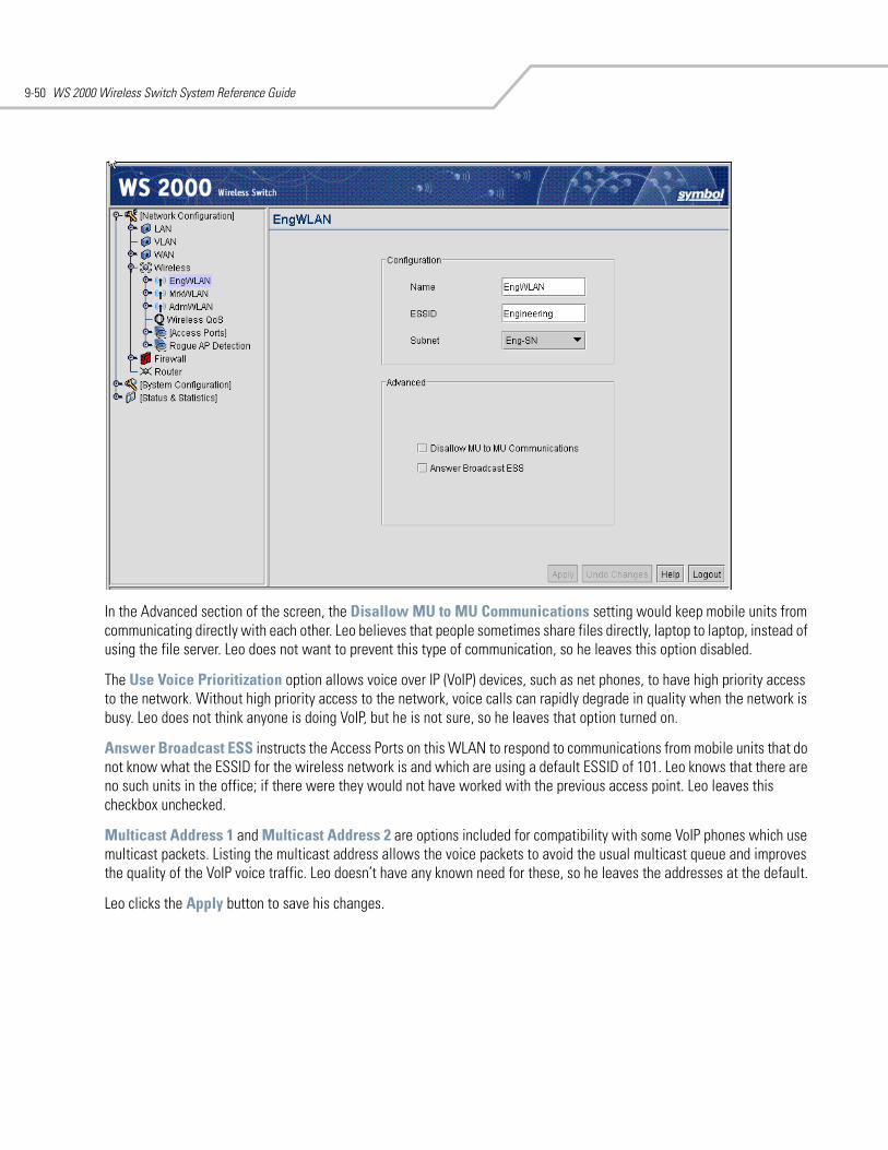
WS 2000 Wireless Switch System Reference Guide9-50
In the Advanced section of the screen, the Disallow MU to MU Communications setting would keep mobile units from communicating directly with each other. Leo believes that people sometimes share files directly, laptop to laptop, instead of using the file server. Leo does not want to prevent this type of communication, so he leaves this option disabled.
The Use Voice Prioritization option allows voice over IP (VoIP) devices, such as net phones, to have high priority access to the network. Without high priority access to the network, voice calls can rapidly degrade in quality when the network is busy. Leo does not think anyone is doing VoIP, but he is not sure, so he leaves that option turned on.
Answer Broadcast ESS instructs the Access Ports on this WLAN to respond to communications from mobile units that do not know what the ESSID for the wireless network is and which are using a default ESSID of 101. Leo knows that there are no such units in the office; if there were they would not have worked with the previous access point. Leo leaves this checkbox unchecked.
Multicast Address 1 and Multicast Address 2 are options included for compatibility with some VoIP phones which use multicast packets. Listing the multicast address allows the voice packets to avoid the usual multicast queue and improves the quality of the VoIP voice traffic. Leo doesn’t have any known need for these, so he leaves the addresses at the default.
Leo clicks the Apply button to save his changes.
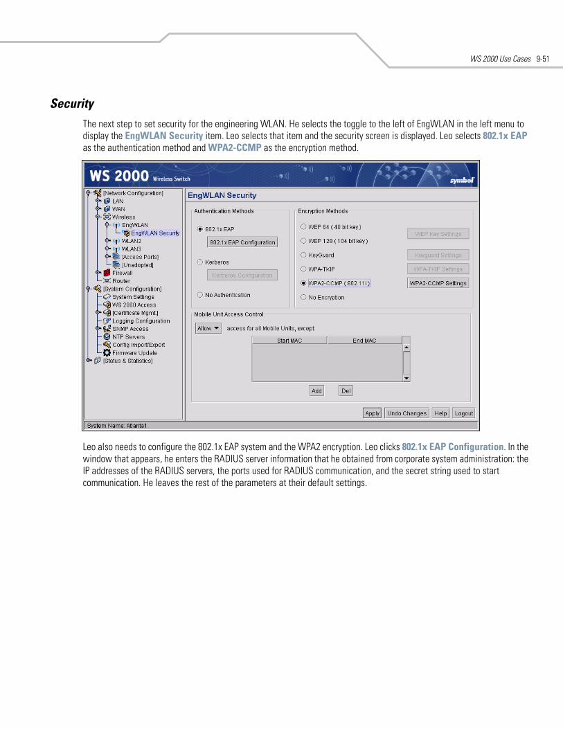
WS 2000 Use Cases 9-51
SecurityThe next step to set security for the engineering WLAN. He selects the toggle to the left of EngWLAN in the left menu to display the EngWLAN Security item. Leo selects that item and the security screen is displayed. Leo selects 802.1x EAP as the authentication method and WPA2-CCMP as the encryption method.
Leo also needs to configure the 802.1x EAP system and the WPA2 encryption. Leo clicks 802.1x EAP Configuration. In the window that appears, he enters the RADIUS server information that he obtained from corporate system administration: the IP addresses of the RADIUS servers, the ports used for RADIUS communication, and the secret string used to start communication. He leaves the rest of the parameters at their default settings.
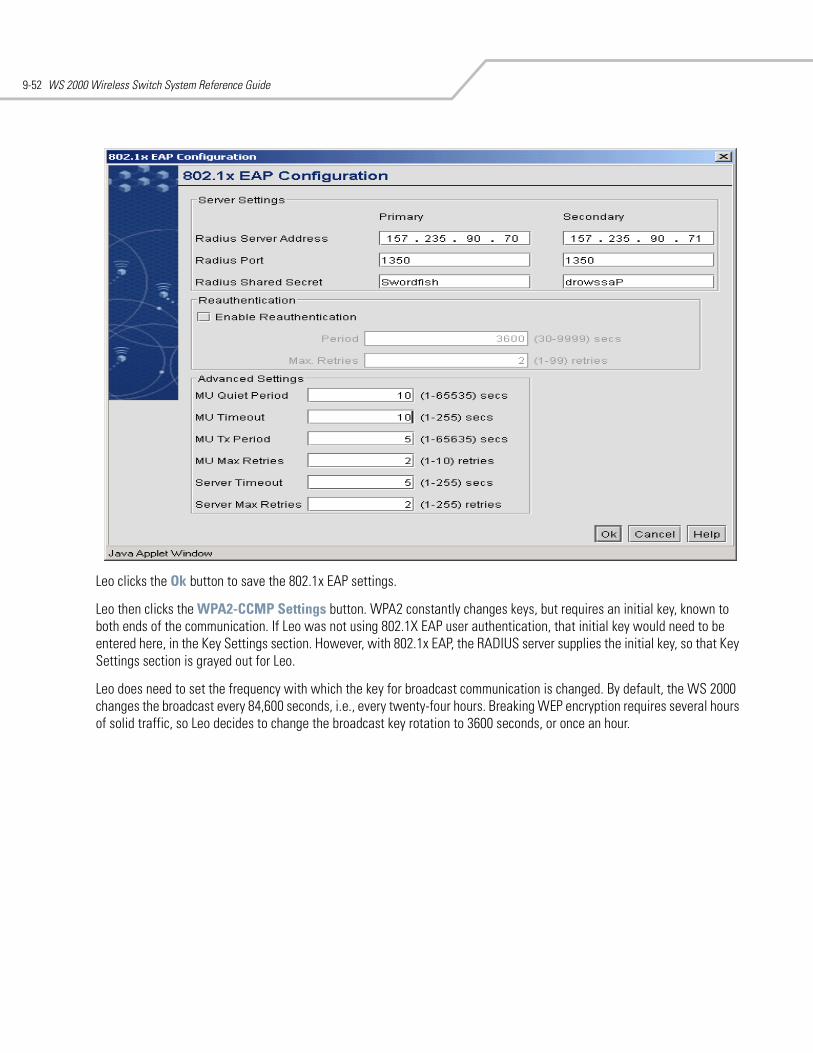
WS 2000 Wireless Switch System Reference Guide9-52
Leo clicks the Ok button to save the 802.1x EAP settings.
Leo then clicks the WPA2-CCMP Settings button. WPA2 constantly changes keys, but requires an initial key, known to both ends of the communication. If Leo was not using 802.1X EAP user authentication, that initial key would need to be entered here, in the Key Settings section. However, with 802.1x EAP, the RADIUS server supplies the initial key, so that Key Settings section is grayed out for Leo.
Leo does need to set the frequency with which the key for broadcast communication is changed. By default, the WS 2000 changes the broadcast every 84,600 seconds, i.e., every twenty-four hours. Breaking WEP encryption requires several hours of solid traffic, so Leo decides to change the broadcast key rotation to 3600 seconds, or once an hour.
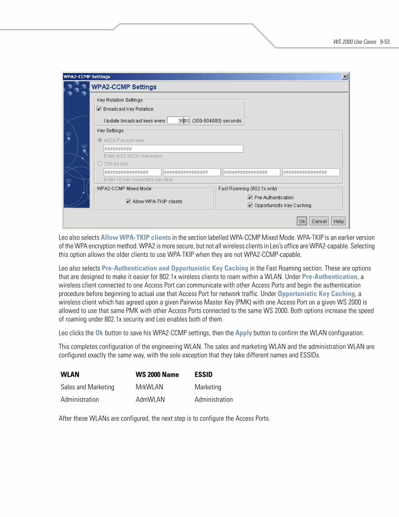
WS 2000 Use Cases 9-53
Leo also selects Allow WPA-TKIP clients in the section labelled WPA-CCMP Mixed Mode. WPA-TKIP is an earlier version of the WPA encryption method. WPA2 is more secure, but not all wireless clients in Leo’s office are WPA2-capable. Selecting this option allows the older clients to use WPA-TKIP when they are not WPA2-CCMP-capable.
Leo also selects Pre-Authentication and Opportunistic Key Caching in the Fast Roaming section. These are options that are designed to make it easier for 802.1x wireless clients to roam within a WLAN. Under Pre-Authentication, a wireless client connected to one Access Port can communicate with other Access Ports and begin the authentication procedure before beginning to actual use that Access Port for network traffic. Under Opportunistic Key Caching, a wireless client which has agreed upon a given Pairwise Master Key (PMK) with one Access Port on a given WS 2000 is allowed to use that same PMK with other Access Ports connected to the same WS 2000. Both options increase the speed of roaming under 802.1x security and Leo enables both of them.
Leo clicks the Ok button to save his WPA2-CCMP settings, then the Apply button to confirm the WLAN configuration.
This completes configuration of the engineering WLAN. The sales and marketing WLAN and the administration WLAN are configured exactly the same way, with the sole exception that they take different names and ESSIDs.
After these WLANs are configured, the next step is to configure the Access Ports.
WLAN WS 2000 Name ESSID
Sales and Marketing MrkWLAN Marketing
Administration AdmWLAN Administration
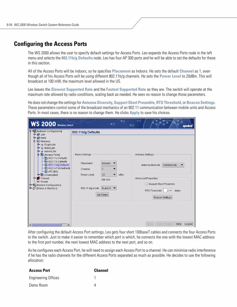
WS 2000 Wireless Switch System Reference Guide9-54
Configuring the Access PortsThe WS 2000 allows the user to specify default settings for Access Ports. Leo expands the Access Ports node in the left menu and selects the 802.11b/g Defaults node. Leo has four AP 300 ports and he will be able to set the defaults for these in this section.
All of the Access Ports will be indoors, so he specifies Placement as Indoors. He sets the default Channel as 1, even though all of his Access Ports will be using different 802.11b/g channels. He sets the Power Level to 20dBm. This will broadcast at 100 mW, the maximum level allowed in the US.
Leo leaves the Slowest Supported Rate and the Fastest Supported Rate as they are. The switch will operate at the maximum rate allowed by radio conditions, scaling back as needed. He sees no reason to change those parameters.
He does not change the settings for Antenna Diversity, Support Short Preamble, RTS Threshold, or Beacon Settings. These parameters control some of the broadcast mechanics of an 802.11 communication between mobile units and Access Ports. In most cases, there is no reason to change them. He clicks Apply to save his choices.
After configuring the default Access Port settings, Leo gets four short 100baseT cables and connects the four Access Ports to the switch. Just to make it easier to remember which port is which, he connects the one with the lowest MAC address to the first port number, the next lowest MAC address to the next port, and so on.
As he configures each Access Port, he will need to assign each Access Port to a channel. He can minimize radio interference if he has the radio channels for the different Access Ports separated as much as possible. He decides to use the following allocation:
Access Port Channel
Engineering Offices 1
Demo Room 4
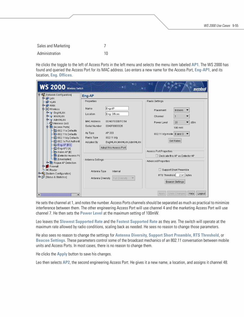
WS 2000 Use Cases 9-55
He clicks the toggle to the left of Access Ports in the left menu and selects the menu item labeled AP1. The WS 2000 has found and queried the Access Port for its MAC address. Leo enters a new name for the Access Port, Eng-AP1, and its location, Eng. Offices.
He sets the channel at 1, and notes the number. Access Ports channels should be separated as much as practical to minimize interference between them. The other engineering Access Port will use channel 4 and the marketing Access Port will use channel 7. He then sets the Power Level at the maximum setting of 100mW.
Leo leaves the Slowest Supported Rate and the Fastest Supported Rate as they are. The switch will operate at the maximum rate allowed by radio conditions, scaling back as needed. He sees no reason to change those parameters.
He also sees no reason to change the settings for Antenna Diversity, Support Short Preamble, RTS Threshold, or Beacon Settings. These parameters control some of the broadcast mechanics of an 802.11 conversation between mobile units and Access Ports. In most cases, there is no reason to change them.
He clicks the Apply button to save his changes.
Leo then selects AP2, the second engineering Access Port. He gives it a new name, a location, and assigns it channel 48.
Sales and Marketing 7
Administration 10
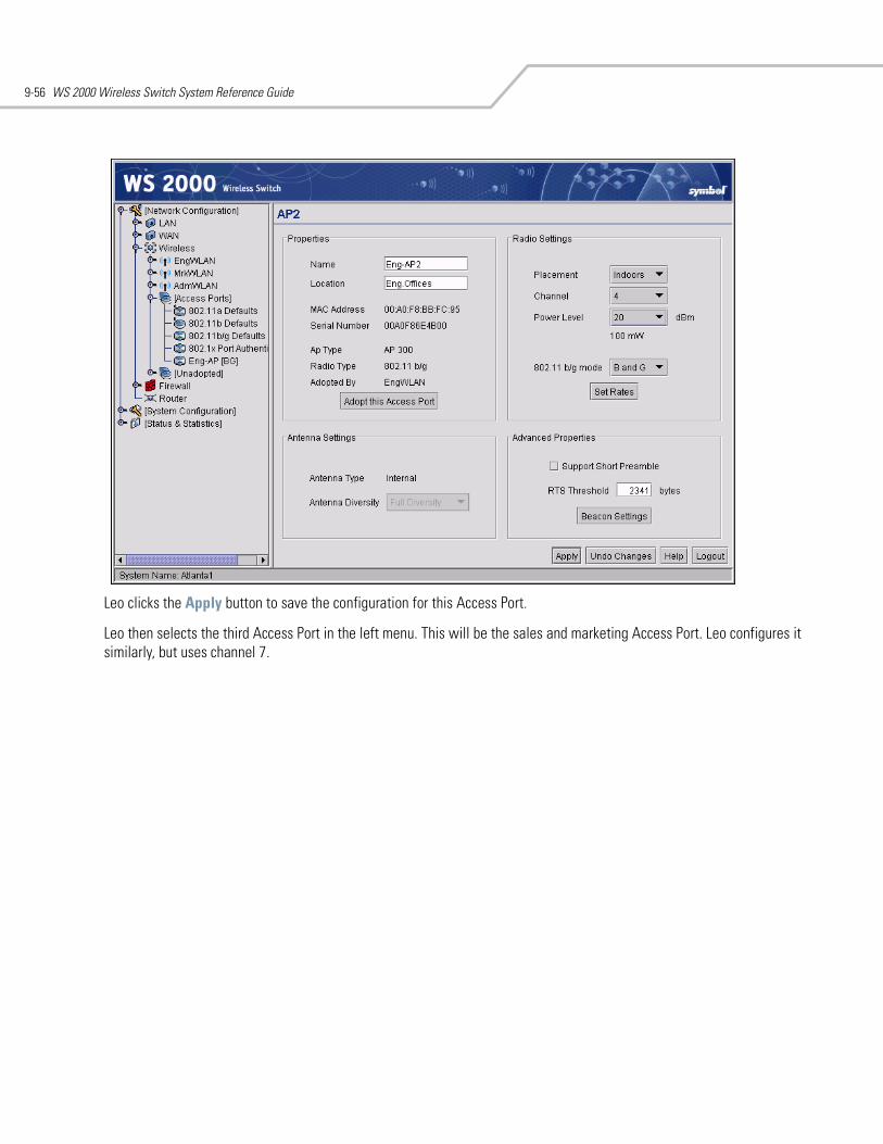
WS 2000 Wireless Switch System Reference Guide9-56
Leo clicks the Apply button to save the configuration for this Access Port.
Leo then selects the third Access Port in the left menu. This will be the sales and marketing Access Port. Leo configures it similarly, but uses channel 7.
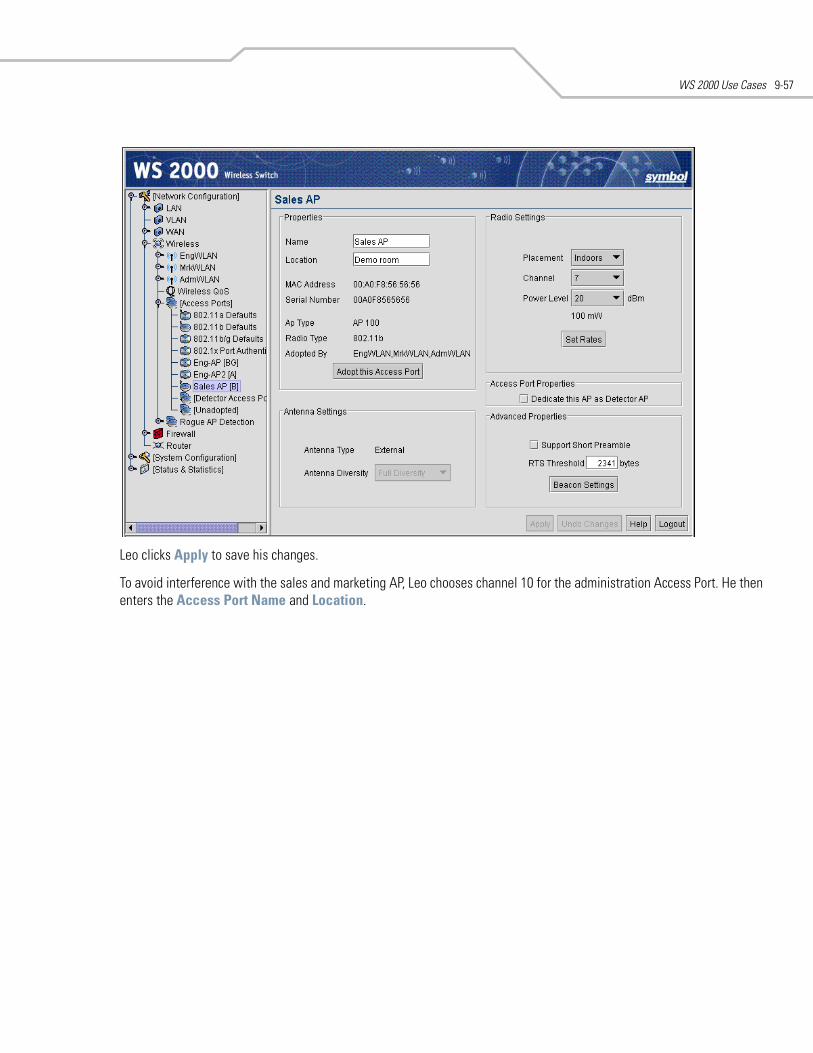
WS 2000 Use Cases 9-57
Leo clicks Apply to save his changes.
To avoid interference with the sales and marketing AP, Leo chooses channel 10 for the administration Access Port. He then enters the Access Port Name and Location.
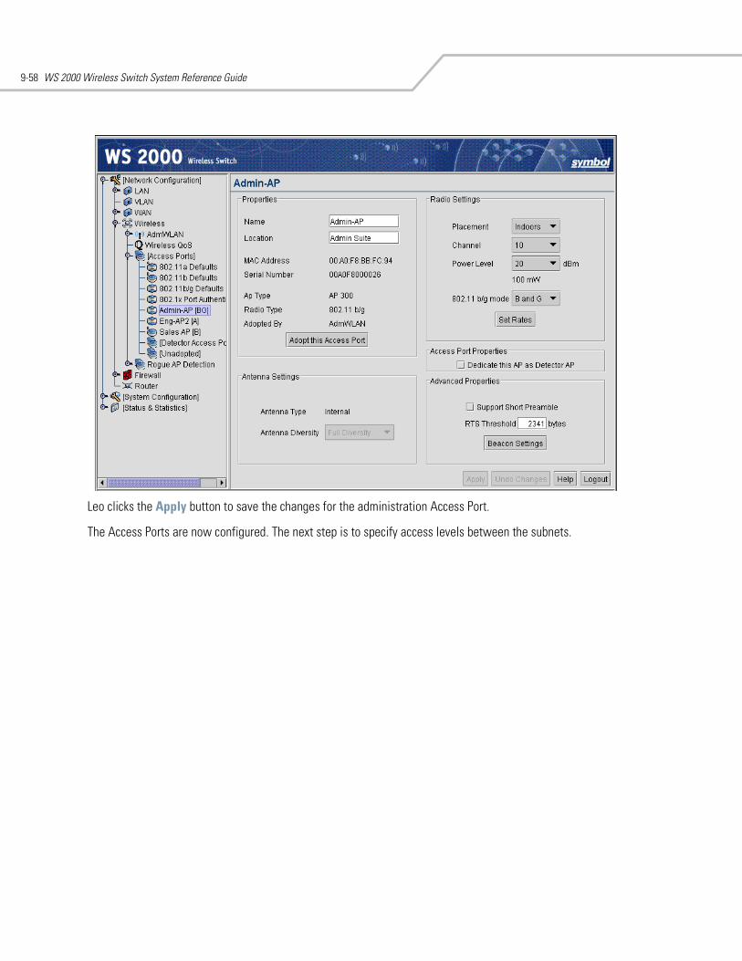
WS 2000 Wireless Switch System Reference Guide9-58
Leo clicks the Apply button to save the changes for the administration Access Port.
The Access Ports are now configured. The next step is to specify access levels between the subnets.
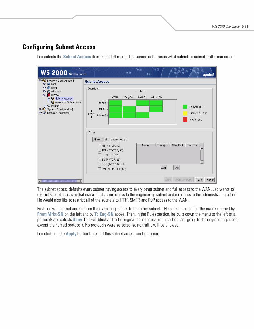
WS 2000 Use Cases 9-59
Configuring Subnet Access Leo selects the Subnet Access item in the left menu. This screen determines what subnet-to-subnet traffic can occur.
The subnet access defaults every subnet having access to every other subnet and full access to the WAN. Leo wants to restrict subnet access to that marketing has no access to the engineering subnet and no access to the administration subnet. He would also like to restrict all of the subnets to HTTP, SMTP, and POP access to the WAN.
First Leo will restrict access from the marketing subnet to the other subnets. He selects the cell in the matrix defined by From Mrkt-SN on the left and by To Eng-SN above. Then, in the Rules section, he pulls down the menu to the left of all protocols and selects Deny. This will block all traffic originating in the marketing subnet and going to the engineering subnet except the named protocols. No protocols were selected, so no traffic will be allowed.
Leo clicks on the Apply button to record this subnet access configuration.
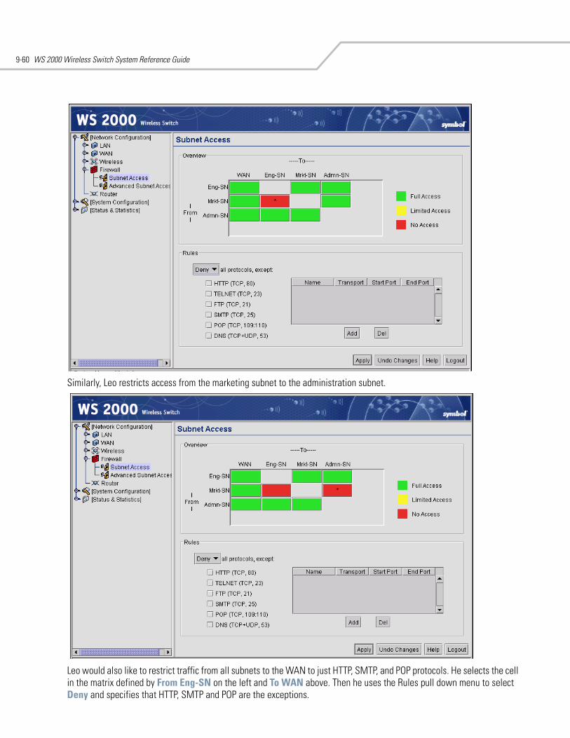
WS 2000 Wireless Switch System Reference Guide9-60
Similarly, Leo restricts access from the marketing subnet to the administration subnet.
Leo would also like to restrict traffic from all subnets to the WAN to just HTTP, SMTP, and POP protocols. He selects the cell in the matrix defined by From Eng-SN on the left and To WAN above. Then he uses the Rules pull down menu to select Deny and specifies that HTTP, SMTP and POP are the exceptions.
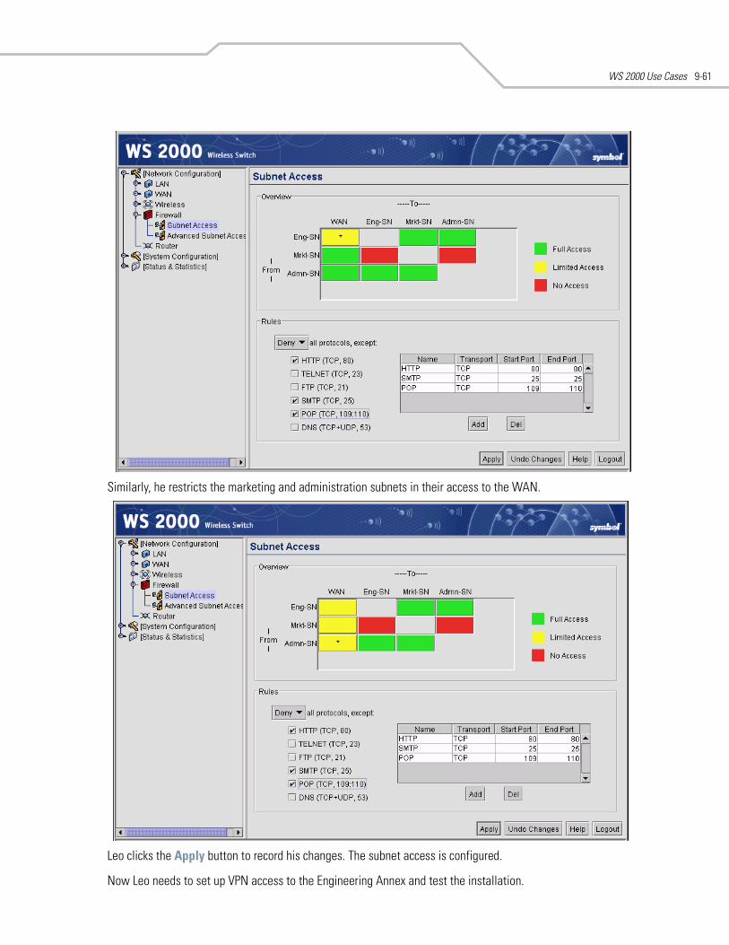
WS 2000 Use Cases 9-61
Similarly, he restricts the marketing and administration subnets in their access to the WAN.
Leo clicks the Apply button to record his changes. The subnet access is configured.
Now Leo needs to set up VPN access to the Engineering Annex and test the installation.
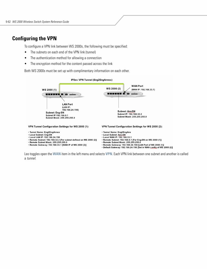
WS 2000 Wireless Switch System Reference Guide9-62
Configuring the VPNTo configure a VPN link between WS 2000s, the following must be specified:
• The subnets on each end of the VPN link (tunnel)
• The authentication method for allowing a connection
• The encryption method for the content passed across the link
Both WS 2000s must be set up with complimentary information on each other.
Leo toggles open the WAN item in the left menu and selects VPN. Each VPN link between one subnet and another is called a tunnel.
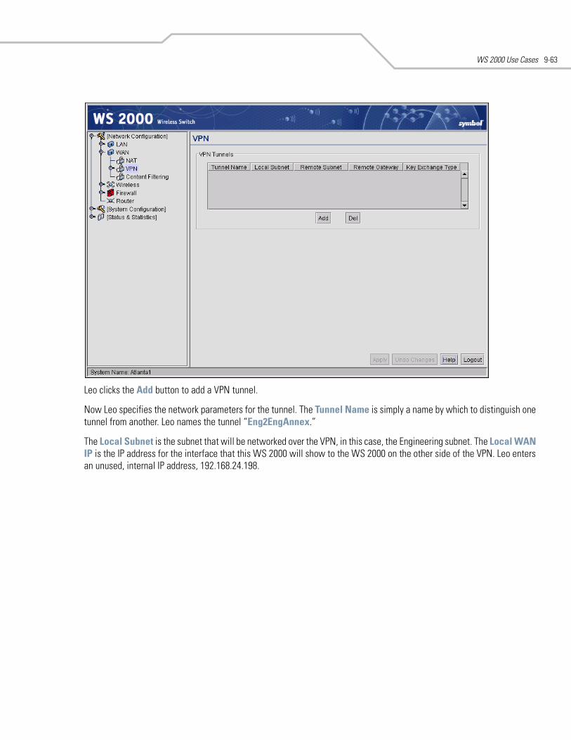
WS 2000 Use Cases 9-63
Leo clicks the Add button to add a VPN tunnel.
Now Leo specifies the network parameters for the tunnel. The Tunnel Name is simply a name by which to distinguish one tunnel from another. Leo names the tunnel “Eng2EngAnnex.”
The Local Subnet is the subnet that will be networked over the VPN, in this case, the Engineering subnet. The Local WAN IP is the IP address for the interface that this WS 2000 will show to the WS 2000 on the other side of the VPN. Leo enters an unused, internal IP address, 192.168.24.198.
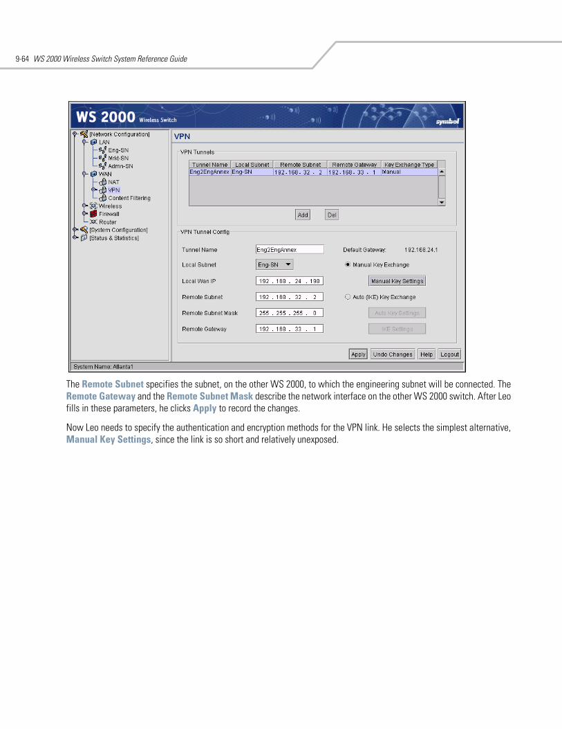
WS 2000 Wireless Switch System Reference Guide9-64
The Remote Subnet specifies the subnet, on the other WS 2000, to which the engineering subnet will be connected. The Remote Gateway and the Remote Subnet Mask describe the network interface on the other WS 2000 switch. After Leo fills in these parameters, he clicks Apply to record the changes.
Now Leo needs to specify the authentication and encryption methods for the VPN link. He selects the simplest alternative, Manual Key Settings, since the link is so short and relatively unexposed.
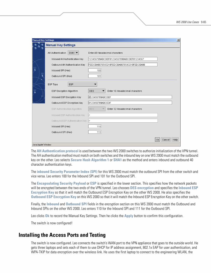
WS 2000 Use Cases 9-65
The AH Authentication protocol is used between the two WS 2000 switches to authorize initialization of the VPN tunnel. The AH authentication method must match on both switches and the inbound key on one WS 2000 must match the outbound key on the other. Leo selects Secure Hash Algorithm 1 or SHA1 as the method and enters inbound and outbound 40 character authentication keys.
The inbound Security Parameter Index (SPI) for this WS 2000 must match the outbound SPI from the other switch and vice versa. Leo enters 100 for the Inbound SPI and 101 for the Outbound SPI.
The Encapsulating Security Payload or ESP is specified in the lower section. This specifies how the network packets will be encrypted between the two ends of the VPN tunnel. Leo chooses DES encryption and specifies the Inbound ESP Encryption Key so that it will match the Outbound ESP Encryption Key on the other WS 2000. He also specifies the Outbound ESP Encryption Key on this WS 2000 so that it will match the Inbound ESP Encryption Key on the other switch.
Finally, the Inbound and Outbound SPI fields in the encryption section on this WS 2000 must match the Outbound and Inbound SPIs on the other WS 2000. Leo enters 110 for the Inbound SPI and 111 for the Outbound SPI.
Leo clicks Ok to record the Manual Key Settings. Then he clicks the Apply button to confirm this configuration.
The switch is now configured!
Installing the Access Ports and TestingThe switch is now configured. Leo connects the switch’s WAN port to the VPN appliance that goes to the outside world. He gets three laptops and sets each of them to use DHCP for IP address assignment, 802.1x EAP for user authentication, and WPA-TKIP for data encryption over the wireless link. He uses the first laptop to connect to the engineering WLAN, the
WS 2000 Wireless Switch System Reference Guide9-66
second to connect to the sales and marketing WLAN, and the third laptop to connect to the administration WLAN. He makes sure that laptops on each WLAN can connect to the WAN and to each other.
After he has tested the three subnets, he installs the Access Ports in their permanent locations. He test coverage with the laptops, making sure each Access Port is covering its assigned area. He also unplugs each of the engineering Access Ports, in turn, to be sure that both are working properly. When everything seems to be working, he sends an email to the users telling them that the new wireless network is up and running!
10Command Line Interface Reference
Admin and Common Commands . . . . . . . . . . . . . . . . . . . . . . . . . . . . . . . . . . . . . . . . . . . . . . . . . . . . . . . 10-3Network Commands. . . . . . . . . . . . . . . . . . . . . . . . . . . . . . . . . . . . . . . . . . . . . . . . . . . . . . . . . . . . . . . . 10-13Network AP Commands . . . . . . . . . . . . . . . . . . . . . . . . . . . . . . . . . . . . . . . . . . . . . . . . . . . . . . . . . . . . . 10-14Network AP Default Commands . . . . . . . . . . . . . . . . . . . . . . . . . . . . . . . . . . . . . . . . . . . . . . . . . . . . . . 10-24Network AP Test Commands . . . . . . . . . . . . . . . . . . . . . . . . . . . . . . . . . . . . . . . . . . . . . . . . . . . . . . . . . 10-28Network DCHP Commands. . . . . . . . . . . . . . . . . . . . . . . . . . . . . . . . . . . . . . . . . . . . . . . . . . . . . . . . . . . 10-30Network Firewall Commands. . . . . . . . . . . . . . . . . . . . . . . . . . . . . . . . . . . . . . . . . . . . . . . . . . . . . . . . . 10-33Network Firewall Policy Commands . . . . . . . . . . . . . . . . . . . . . . . . . . . . . . . . . . . . . . . . . . . . . . . . . . . 10-37Network Firewall Policy Inbound Commands . . . . . . . . . . . . . . . . . . . . . . . . . . . . . . . . . . . . . . . . . . . . 10-39Network Firewall Policy Outbound Commands . . . . . . . . . . . . . . . . . . . . . . . . . . . . . . . . . . . . . . . . . . . 10-46Network Firewall Submap Commands. . . . . . . . . . . . . . . . . . . . . . . . . . . . . . . . . . . . . . . . . . . . . . . . . . 10-53Network LAN Commands. . . . . . . . . . . . . . . . . . . . . . . . . . . . . . . . . . . . . . . . . . . . . . . . . . . . . . . . . . . . 10-59Network LAN DHCP Commands. . . . . . . . . . . . . . . . . . . . . . . . . . . . . . . . . . . . . . . . . . . . . . . . . . . . . . . 10-62Network QoS Commands . . . . . . . . . . . . . . . . . . . . . . . . . . . . . . . . . . . . . . . . . . . . . . . . . . . . . . . . . . . . 10-68Network Router Commands . . . . . . . . . . . . . . . . . . . . . . . . . . . . . . . . . . . . . . . . . . . . . . . . . . . . . . . . . . 10-72Network VLAN Commands. . . . . . . . . . . . . . . . . . . . . . . . . . . . . . . . . . . . . . . . . . . . . . . . . . . . . . . . . . . 10-78Network VLAN Trunk Commands. . . . . . . . . . . . . . . . . . . . . . . . . . . . . . . . . . . . . . . . . . . . . . . . . . . . . . 10-81Network WAN Commands. . . . . . . . . . . . . . . . . . . . . . . . . . . . . . . . . . . . . . . . . . . . . . . . . . . . . . . . . . . 10-85Network WAN App Commands . . . . . . . . . . . . . . . . . . . . . . . . . . . . . . . . . . . . . . . . . . . . . . . . . . . . . . . 10-89Network WAN NAT Commands. . . . . . . . . . . . . . . . . . . . . . . . . . . . . . . . . . . . . . . . . . . . . . . . . . . . . . . 10-95Network WAN VPN Commands. . . . . . . . . . . . . . . . . . . . . . . . . . . . . . . . . . . . . . . . . . . . . . . . . . . . . . 10-101Network WAN VPN Cmgr Commands . . . . . . . . . . . . . . . . . . . . . . . . . . . . . . . . . . . . . . . . . . . . . . . . . 10-112Network WLAN Commands . . . . . . . . . . . . . . . . . . . . . . . . . . . . . . . . . . . . . . . . . . . . . . . . . . . . . . . . . 10-125Network WLAN Rogue AP Commands . . . . . . . . . . . . . . . . . . . . . . . . . . . . . . . . . . . . . . . . . . . . . . . . 10-135
WS 2000 Wireless Switch System Reference Guide10-2
Network WLAN Rogue AP Approved AP List Commands . . . . . . . . . . . . . . . . . . . . . . . . . . . . . . . . . .10-138Network WLAN Rogue AP List Commands . . . . . . . . . . . . . . . . . . . . . . . . . . . . . . . . . . . . . . . . . . . . .10-143Network WLAN Rogue AP Locate Commands . . . . . . . . . . . . . . . . . . . . . . . . . . . . . . . . . . . . . . . . . . .10-148Network WLAN Rogue AP MU Scan Commands. . . . . . . . . . . . . . . . . . . . . . . . . . . . . . . . . . . . . . . . .10-151Network WLAN Rogue AP Rule List Commands . . . . . . . . . . . . . . . . . . . . . . . . . . . . . . . . . . . . . . . . .10-154Statistics Commands . . . . . . . . . . . . . . . . . . . . . . . . . . . . . . . . . . . . . . . . . . . . . . . . . . . . . . . . . . . . . .10-159Statistics RF Commands . . . . . . . . . . . . . . . . . . . . . . . . . . . . . . . . . . . . . . . . . . . . . . . . . . . . . . . . . . . .10-162System Commands . . . . . . . . . . . . . . . . . . . . . . . . . . . . . . . . . . . . . . . . . . . . . . . . . . . . . . . . . . . . . . . .10-167System Authentication Commands . . . . . . . . . . . . . . . . . . . . . . . . . . . . . . . . . . . . . . . . . . . . . . . . . . .10-169System Authentication RADIUS Commands . . . . . . . . . . . . . . . . . . . . . . . . . . . . . . . . . . . . . . . . . . . .10-172System Configuration Commands . . . . . . . . . . . . . . . . . . . . . . . . . . . . . . . . . . . . . . . . . . . . . . . . . . . .10-175System Logs Commands. . . . . . . . . . . . . . . . . . . . . . . . . . . . . . . . . . . . . . . . . . . . . . . . . . . . . . . . . . . .10-184System NTP Commands . . . . . . . . . . . . . . . . . . . . . . . . . . . . . . . . . . . . . . . . . . . . . . . . . . . . . . . . . . . .10-190System RADIUS Commands . . . . . . . . . . . . . . . . . . . . . . . . . . . . . . . . . . . . . . . . . . . . . . . . . . . . . . . . .10-193System RADIUS Client Commands. . . . . . . . . . . . . . . . . . . . . . . . . . . . . . . . . . . . . . . . . . . . . . . . . . . .10-196System RADIUS EAP Commands . . . . . . . . . . . . . . . . . . . . . . . . . . . . . . . . . . . . . . . . . . . . . . . . . . . . .10-200System RADIUS EAP PEAP Commands . . . . . . . . . . . . . . . . . . . . . . . . . . . . . . . . . . . . . . . . . . . . . . . .10-204System RADIUS EAP TTLS Commands. . . . . . . . . . . . . . . . . . . . . . . . . . . . . . . . . . . . . . . . . . . . . . . . .10-207System RADIUS LDAP Commands . . . . . . . . . . . . . . . . . . . . . . . . . . . . . . . . . . . . . . . . . . . . . . . . . . . .10-210System RADIUS Policy Commands. . . . . . . . . . . . . . . . . . . . . . . . . . . . . . . . . . . . . . . . . . . . . . . . . . . .10-213System RADIUS Proxy Commands . . . . . . . . . . . . . . . . . . . . . . . . . . . . . . . . . . . . . . . . . . . . . . . . . . . .10-216System Redundancy Commands . . . . . . . . . . . . . . . . . . . . . . . . . . . . . . . . . . . . . . . . . . . . . . . . . . . . .10-221System SNMP Commands . . . . . . . . . . . . . . . . . . . . . . . . . . . . . . . . . . . . . . . . . . . . . . . . . . . . . . . . . .10-224System SNMP Access Commands . . . . . . . . . . . . . . . . . . . . . . . . . . . . . . . . . . . . . . . . . . . . . . . . . . . .10-225System SNMP Traps Commands . . . . . . . . . . . . . . . . . . . . . . . . . . . . . . . . . . . . . . . . . . . . . . . . . . . . .10-232System SSH Commands . . . . . . . . . . . . . . . . . . . . . . . . . . . . . . . . . . . . . . . . . . . . . . . . . . . . . . . . . . . .10-243System User Database Commands . . . . . . . . . . . . . . . . . . . . . . . . . . . . . . . . . . . . . . . . . . . . . . . . . . .10-246System User Database Group Commands . . . . . . . . . . . . . . . . . . . . . . . . . . . . . . . . . . . . . . . . . . . . . .10-247System User Database User Commands . . . . . . . . . . . . . . . . . . . . . . . . . . . . . . . . . . . . . . . . . . . . . . .10-253System WS2000 Commands . . . . . . . . . . . . . . . . . . . . . . . . . . . . . . . . . . . . . . . . . . . . . . . . . . . . . . . .10-258
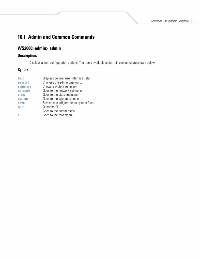
Command Line Interface Reference 10-3
10.1 Admin and Common Commands
WS2000>admin> admin
Description:
Displays admin configuration options. The items available under this command are shown below.
Syntax:
help Displays general user interface help. passwd Changes the admin password. summary Shows a system summary. network Goes to the network submenu stats Goes to the stats submenu. system Goes to the system submenu. save Saves the configuration to system flash.quit Quits the CLI. .. Goes to the parent menu./ Goes to the root menu.
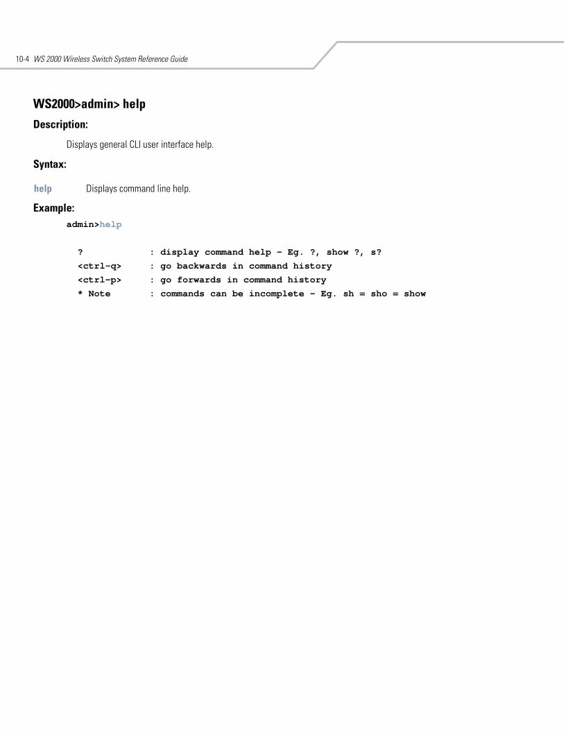
WS 2000 Wireless Switch System Reference Guide10-4
WS2000>admin> help
Description:
Displays general CLI user interface help.
Syntax:
Example: admin>help
? : display command help - Eg. ?, show ?, s?
<ctrl-q> : go backwards in command history
<ctrl-p> : go forwards in command history
* Note : commands can be incomplete - Eg. sh = sho = show
help Displays command line help.
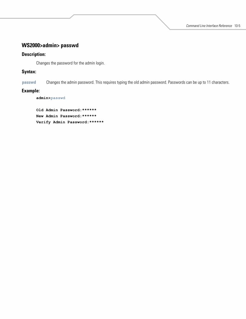
Command Line Interface Reference 10-5
WS2000>admin> passwd
Description:
Changes the password for the admin login.
Syntax:
Example:admin>passwd
Old Admin Password:******
New Admin Password:******
Verify Admin Password:******
passwd Changes the admin password. This requires typing the old admin password. Passwords can be up to 11 characters.
WS 2000 Wireless Switch System Reference Guide10-6
WS2000>admin> quit
Description:
Quits the command line interface.
This command appears in all of the submenus under admin. In each case, it has the same function, to exit out of the CLI.
Example:ws2000>admin>quit
Command Line Interface Reference 10-7
WS2000>admin> save
Description:
Saves the configuration to system flash.
This command appears in all of the submenus under admin. In each case, it has the same function, to save the configuration.
Syntax:
Example: admin>save
admin>
save Saves configuration settings. This command works at all levels of the CLI. The save command must be issued before leaving the UI for the settings to be retained.
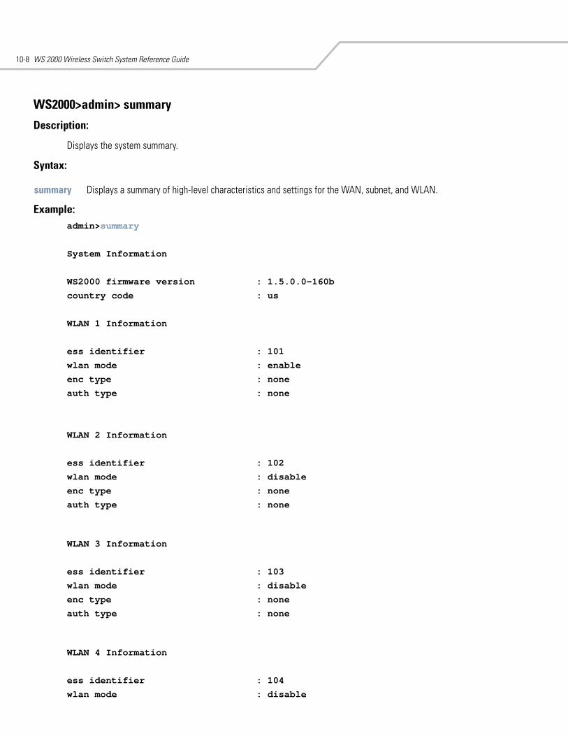
WS 2000 Wireless Switch System Reference Guide10-8
WS2000>admin> summary
Description:
Displays the system summary.
Syntax:
Example:admin>summary
System Information
WS2000 firmware version : 1.5.0.0-160b
country code : us
WLAN 1 Information
ess identifier : 101
wlan mode : enable
enc type : none
auth type : none
WLAN 2 Information
ess identifier : 102
wlan mode : disable
enc type : none
auth type : none
WLAN 3 Information
ess identifier : 103
wlan mode : disable
enc type : none
auth type : none
WLAN 4 Information
ess identifier : 104
wlan mode : disable
summary Displays a summary of high-level characteristics and settings for the WAN, subnet, and WLAN.
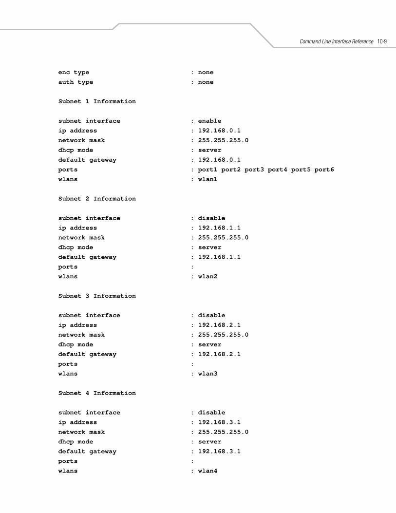
Command Line Interface Reference 10-9
enc type : none
auth type : none
Subnet 1 Information
subnet interface : enable
ip address : 192.168.0.1
network mask : 255.255.255.0
dhcp mode : server
default gateway : 192.168.0.1
ports : port1 port2 port3 port4 port5 port6
wlans : wlan1
Subnet 2 Information
subnet interface : disable
ip address : 192.168.1.1
network mask : 255.255.255.0
dhcp mode : server
default gateway : 192.168.1.1
ports :
wlans : wlan2
Subnet 3 Information
subnet interface : disable
ip address : 192.168.2.1
network mask : 255.255.255.0
dhcp mode : server
default gateway : 192.168.2.1
ports :
wlans : wlan3
Subnet 4 Information
subnet interface : disable
ip address : 192.168.3.1
network mask : 255.255.255.0
dhcp mode : server
default gateway : 192.168.3.1
ports :
wlans : wlan4
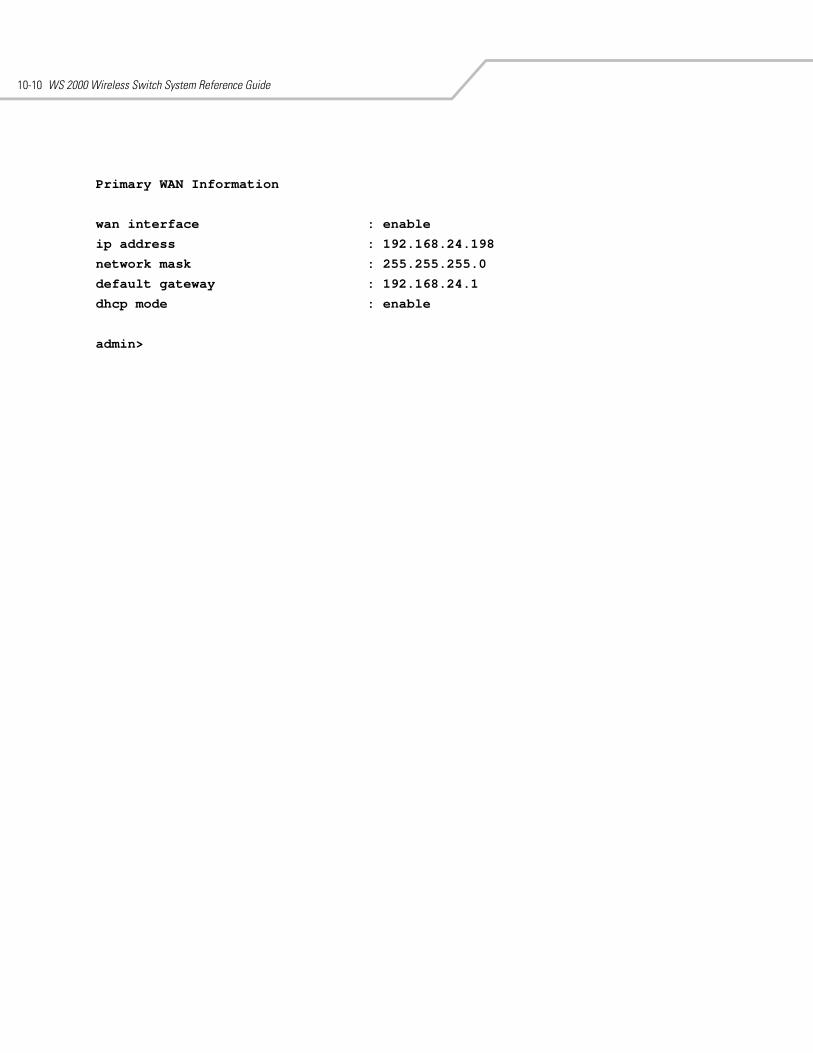
WS 2000 Wireless Switch System Reference Guide10-10
Primary WAN Information
wan interface : enable
ip address : 192.168.24.198
network mask : 255.255.255.0
default gateway : 192.168.24.1
dhcp mode : enable
admin>
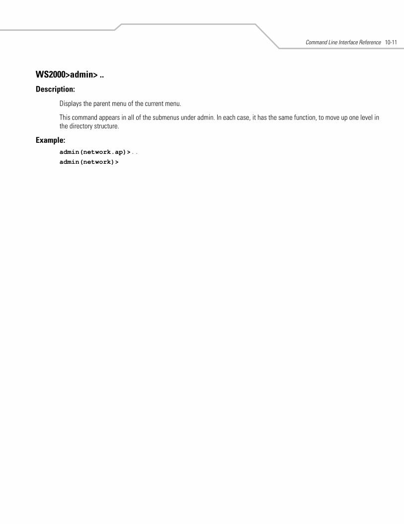
Command Line Interface Reference 10-11
WS2000>admin> ..
Description:
Displays the parent menu of the current menu.
This command appears in all of the submenus under admin. In each case, it has the same function, to move up one level in the directory structure.
Example: admin(network.ap)>..
admin(network)>
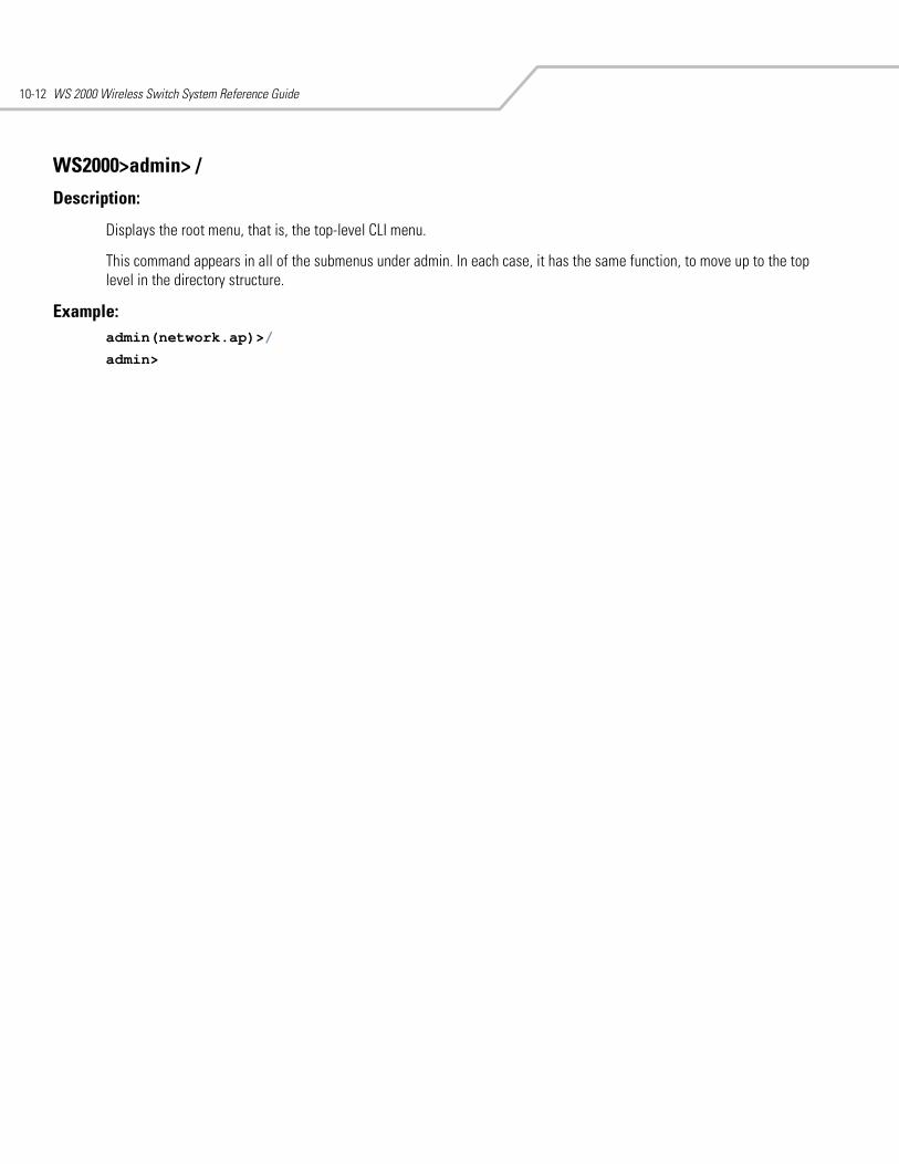
WS 2000 Wireless Switch System Reference Guide10-12
WS2000>admin> /
Description:
Displays the root menu, that is, the top-level CLI menu.
This command appears in all of the submenus under admin. In each case, it has the same function, to move up to the top level in the directory structure.
Example:admin(network.ap)>/
admin>
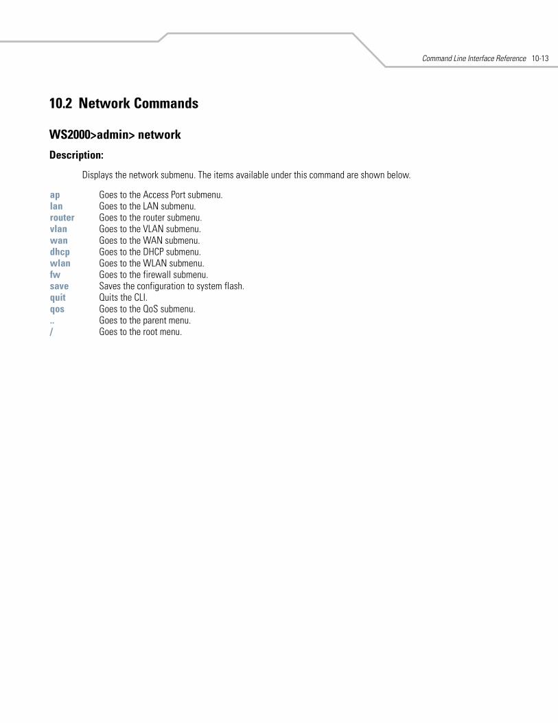
Command Line Interface Reference 10-13
10.2 Network Commands
WS2000>admin> network
Description:
Displays the network submenu. The items available under this command are shown below.
ap Goes to the Access Port submenu. lan Goes to the LAN submenu.router Goes to the router submenu.vlan Goes to the VLAN submenu. wan Goes to the WAN submenu.dhcp Goes to the DHCP submenu. wlan Goes to the WLAN submenu.fw Goes to the firewall submenu.save Saves the configuration to system flash.quit Quits the CLI. qos Goes to the QoS submenu... Goes to the parent menu./ Goes to the root menu.
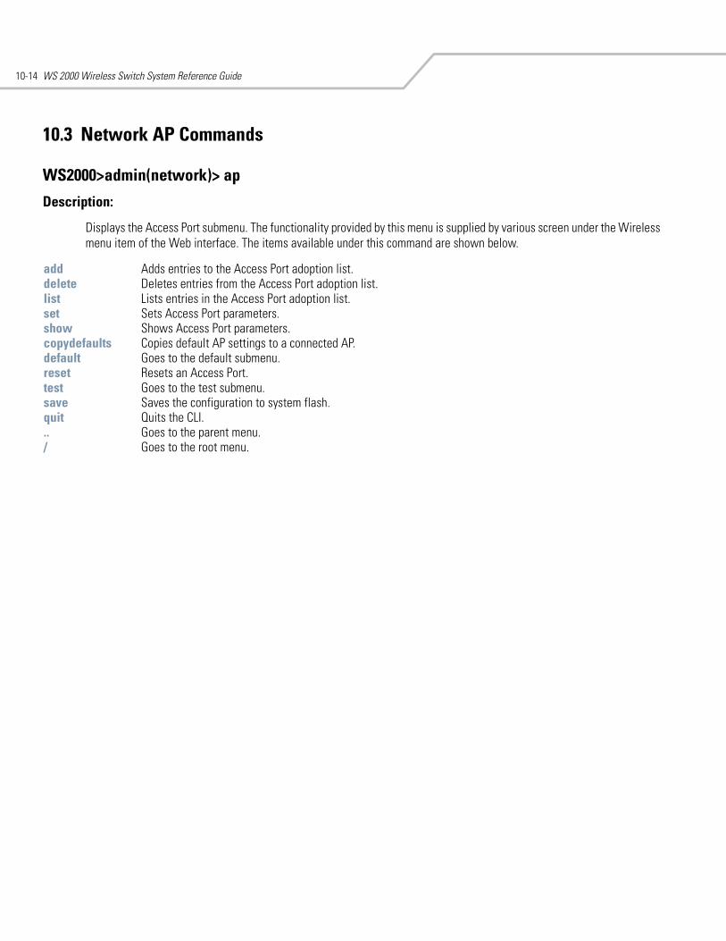
WS 2000 Wireless Switch System Reference Guide10-14
10.3 Network AP Commands
WS2000>admin(network)> ap
Description:
Displays the Access Port submenu. The functionality provided by this menu is supplied by various screen under the Wireless menu item of the Web interface. The items available under this command are shown below.
add Adds entries to the Access Port adoption list.delete Deletes entries from the Access Port adoption list.list Lists entries in the Access Port adoption list.set Sets Access Port parameters.show Shows Access Port parameters.copydefaults Copies default AP settings to a connected AP. default Goes to the default submenu.reset Resets an Access Port.test Goes to the test submenu. save Saves the configuration to system flash.quit Quits the CLI. .. Goes to the parent menu./ Goes to the root menu.
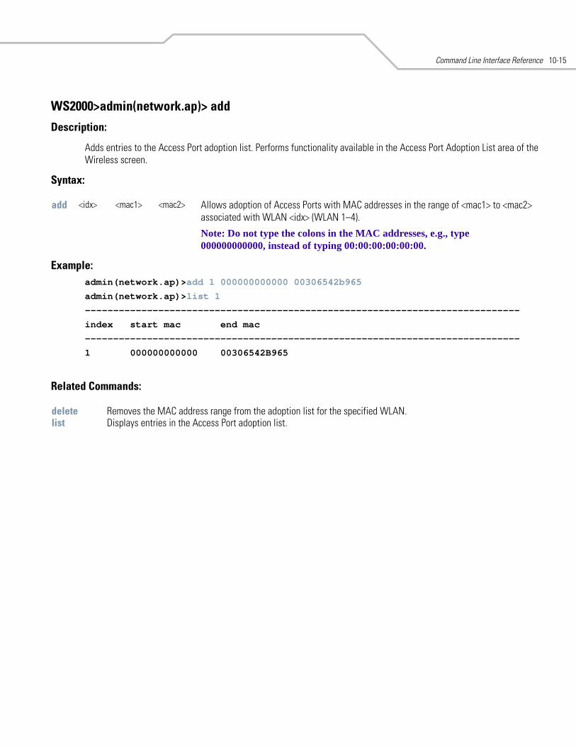
Command Line Interface Reference 10-15
WS2000>admin(network.ap)> add
Description:
Adds entries to the Access Port adoption list. Performs functionality available in the Access Port Adoption List area of the Wireless screen.
Syntax:
Example: admin(network.ap)>add 1 000000000000 00306542b965
admin(network.ap)>list 1
-----------------------------------------------------------------------------
index start mac end mac
-----------------------------------------------------------------------------
1 000000000000 00306542B965
Related Commands:
add <idx> <mac1> <mac2> Allows adoption of Access Ports with MAC addresses in the range of <mac1> to <mac2> associated with WLAN <idx> (WLAN 1–4).
Note: Do not type the colons in the MAC addresses, e.g., type 000000000000, instead of typing 00:00:00:00:00:00.
delete Removes the MAC address range from the adoption list for the specified WLAN.list Displays entries in the Access Port adoption list.
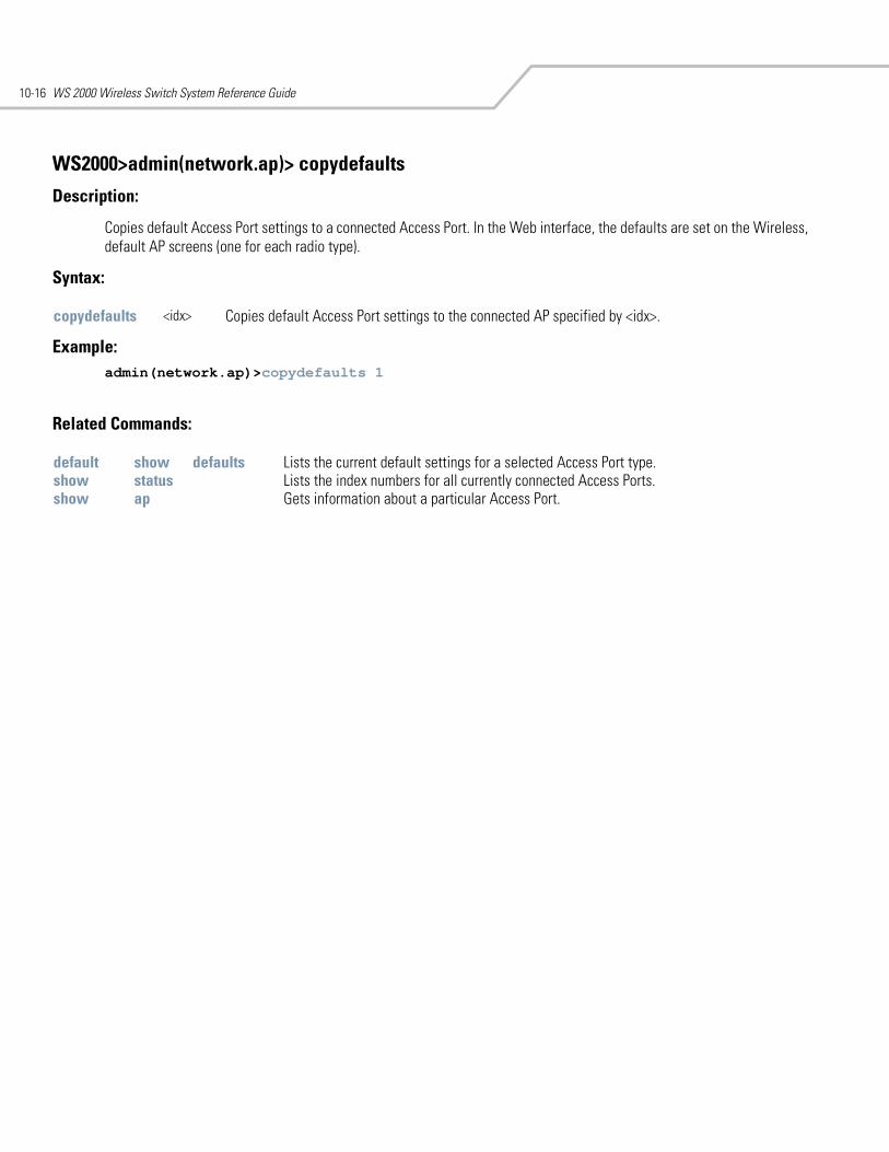
WS 2000 Wireless Switch System Reference Guide10-16
WS2000>admin(network.ap)> copydefaults
Description:
Copies default Access Port settings to a connected Access Port. In the Web interface, the defaults are set on the Wireless, default AP screens (one for each radio type).
Syntax:
Example: admin(network.ap)>copydefaults 1
Related Commands:
copydefaults <idx> Copies default Access Port settings to the connected AP specified by <idx>.
default show defaults Lists the current default settings for a selected Access Port type.show status Lists the index numbers for all currently connected Access Ports.show ap Gets information about a particular Access Port.
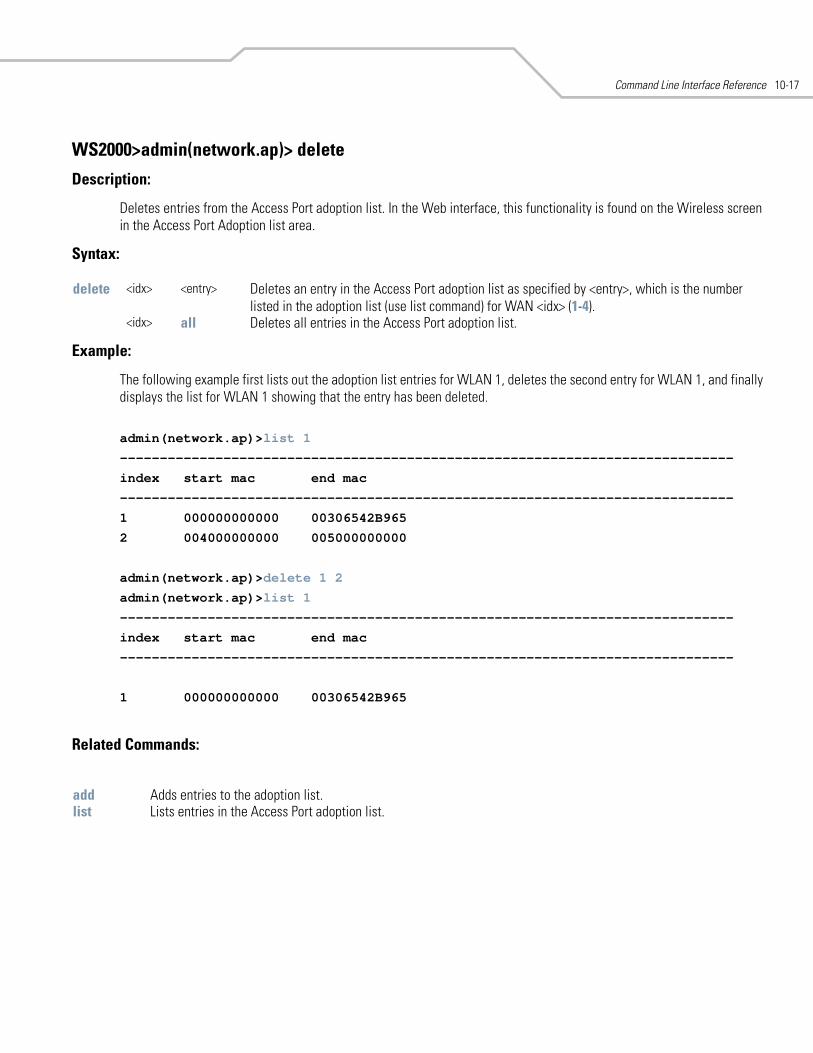
Command Line Interface Reference 10-17
WS2000>admin(network.ap)> delete
Description:
Deletes entries from the Access Port adoption list. In the Web interface, this functionality is found on the Wireless screen in the Access Port Adoption list area.
Syntax:
Example:
The following example first lists out the adoption list entries for WLAN 1, deletes the second entry for WLAN 1, and finally displays the list for WLAN 1 showing that the entry has been deleted.
admin(network.ap)>list 1
-----------------------------------------------------------------------------
index start mac end mac
-----------------------------------------------------------------------------
1 000000000000 00306542B965
2 004000000000 005000000000
admin(network.ap)>delete 1 2
admin(network.ap)>list 1
-----------------------------------------------------------------------------
index start mac end mac
-----------------------------------------------------------------------------
1 000000000000 00306542B965
Related Commands:
delete <idx> <entry> Deletes an entry in the Access Port adoption list as specified by <entry>, which is the number listed in the adoption list (use list command) for WAN <idx> (1-4).
<idx> all Deletes all entries in the Access Port adoption list.
add Adds entries to the adoption list.list Lists entries in the Access Port adoption list.
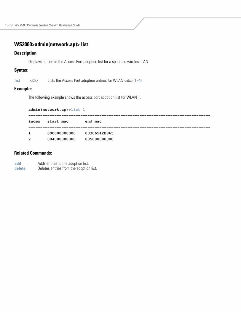
WS 2000 Wireless Switch System Reference Guide10-18
WS2000>admin(network.ap)> list
Description:
Displays entries in the Access Port adoption list for a specified wireless LAN.
Syntax:
Example:
The following example shows the access port adoption list for WLAN 1.
admin(network.ap)>list 1
-----------------------------------------------------------------------------
index start mac end mac
-----------------------------------------------------------------------------
1 000000000000 00306542B965
2 004000000000 005000000000
Related Commands:
list <idx> Lists the Access Port adoption entries for WLAN <idx> (1–4).
add Adds entries to the adoption list.delete Deletes entries from the adoption list.
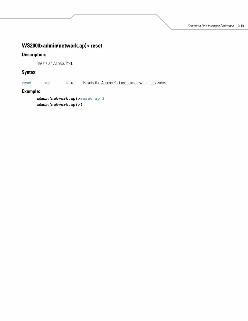
Command Line Interface Reference 10-19
WS2000>admin(network.ap)> reset
Description:
Resets an Access Port.
Syntax:
Example: admin(network.ap)>reset ap 2
admin(network.ap)>?
reset ap <idx> Resets the Access Port associated with index <idx>.
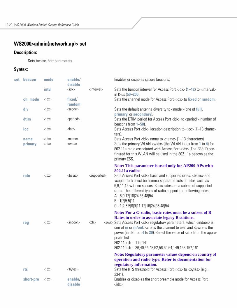
WS 2000 Wireless Switch System Reference Guide10-20
WS2000>admin(network.ap)> set
Description:
Sets Access Port parameters.
Syntax:
set beacon mode enable/disable
Enables or disables secure beacons.
intvl <idx> <interval> Sets the beacon interval for Access Port <idx> (1–12) to <interval> in K-us (50–200).
ch_mode <idx> fixed/random
Sets the channel mode for Access Port <idx> to fixed or random.
div <idx> <mode> Sets the default antenna diversity to <mode> (one of full, primary, or secondary).
dtim <idx> <period> Sets the DTIM period for Access Port <idx> to <period> (number of beacons from 1–50).
loc <idx> <loc> Sets Access Port <idx> location description to <loc> (1–13 charac-ters).
name <idx> <name> Sets Access Port <idx> name to <name> (1–13 characters).primary <idx> <widx> Sets the primary WLAN <widx> (the WLAN index from 1 to 4) for
802.11a radio associated with Access Port <idx>. The ESS ID con-figured for this WLAN will be used in the 802.11a beacon as the primary ESS.
Note: This parameter is used only for AP200 APs with 802.11a radios
rate <idx> <basic> <supported> Sets Access Port <idx> basic and supported rates. <basic> and <supported> must be comma-separated lists of rates, such as 6,9,11,15 with no spaces. Basic rates are a subset of supported rates. The different types of radio support the following rates. A - 6|9|12|18|24|36|48|54 B - 1|2|5.5|11 G - 1|2|5.5|6|9|11|12|18|24|36|48|54
Note: For a G radio, basic rates must be a subset of B Rates in order to associate legacy B stations.
reg <idx> <indoor> <ch> <pwr> Sets Access Port <idx> regulatory parameters, which <indoor> is one of in or in/out; <ch> is the channel to use, and <pwr> is the power (in dB from 4 to 20). Select the value of <ch> from the appro-priate list. 802.11b ch -- 1 to 14 802.11a ch -- 36,40,44,48,52,56,60,64,149,153,157,161
Note: Regulatory parameter values depend on country of operation and radio type. Refer to documentation for regulatory information.
rts <idx> <bytes> Sets the RTS threshold for Access Port <idx> to <bytes> (e.g., 2341).
short-pre <idx> enable/disable
Enables or disables the short preamble mode for Access Port <idx>.
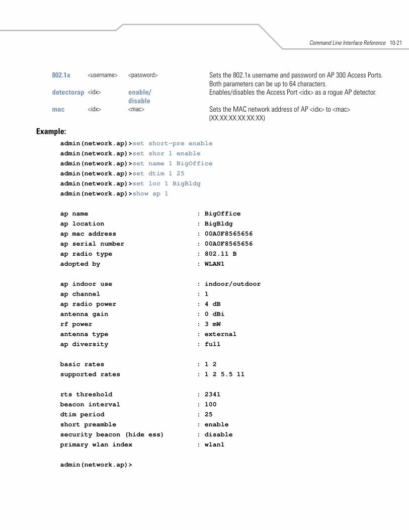
Command Line Interface Reference 10-21
Example:admin(network.ap)>set short-pre enable
admin(network.ap)>set shor 1 enable
admin(network.ap)>set name 1 BigOffice
admin(network.ap)>set dtim 1 25
admin(network.ap)>set loc 1 BigBldg
admin(network.ap)>show ap 1
ap name : BigOffice
ap location : BigBldg
ap mac address : 00A0F8565656
ap serial number : 00A0F8565656
ap radio type : 802.11 B
adopted by : WLAN1
ap indoor use : indoor/outdoor
ap channel : 1
ap radio power : 4 dB
antenna gain : 0 dBi
rf power : 3 mW
antenna type : external
ap diversity : full
basic rates : 1 2
supported rates : 1 2 5.5 11
rts threshold : 2341
beacon interval : 100
dtim period : 25
short preamble : enable
security beacon (hide ess) : disable
primary wlan index : wlan1
admin(network.ap)>
802.1x <username> <password> Sets the 802.1x username and password on AP 300 Access Ports. Both parameters can be up to 64 characters.
detectorap <idx> enable/disable
Enables/disables the Access Port <idx> as a rogue AP detector.
mac <idx> <mac> Sets the MAC network address of AP <idx> to <mac> (XX:XX:XX:XX:XX:XX)
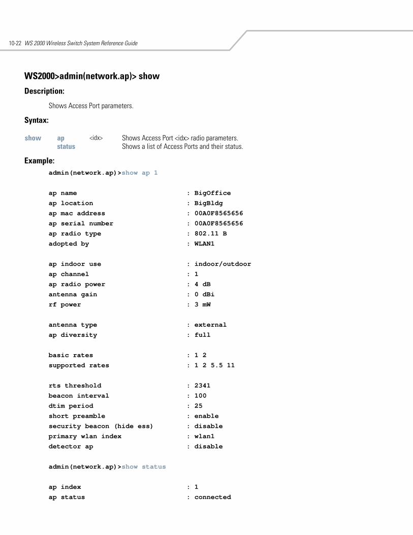
WS 2000 Wireless Switch System Reference Guide10-22
WS2000>admin(network.ap)> show
Description:
Shows Access Port parameters.
Syntax:
Example: admin(network.ap)>show ap 1
ap name : BigOffice
ap location : BigBldg
ap mac address : 00A0F8565656
ap serial number : 00A0F8565656
ap radio type : 802.11 B
adopted by : WLAN1
ap indoor use : indoor/outdoor
ap channel : 1
ap radio power : 4 dB
antenna gain : 0 dBi
rf power : 3 mW
antenna type : external
ap diversity : full
basic rates : 1 2
supported rates : 1 2 5.5 11
rts threshold : 2341
beacon interval : 100
dtim period : 25
short preamble : enable
security beacon (hide ess) : disable
primary wlan index : wlan1
detector ap : disable
admin(network.ap)>show status
ap index : 1
ap status : connected
show ap <idx> Shows Access Port <idx> radio parameters.status Shows a list of Access Ports and their status.
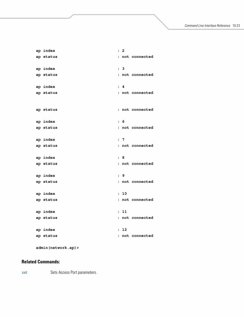
Command Line Interface Reference 10-23
ap index : 2
ap status : not connected
ap index : 3
ap status : not connected
ap index : 4
ap status : not connected
ap status : not connected
ap index : 6
ap status : not connected
ap index : 7
ap status : not connected
ap index : 8
ap status : not connected
ap index : 9
ap status : not connected
ap index : 10
ap status : not connected
ap index : 11
ap status : not connected
ap index : 12
ap status : not connected
admin(network.ap)>
Related Commands:
set Sets Access Port parameters.
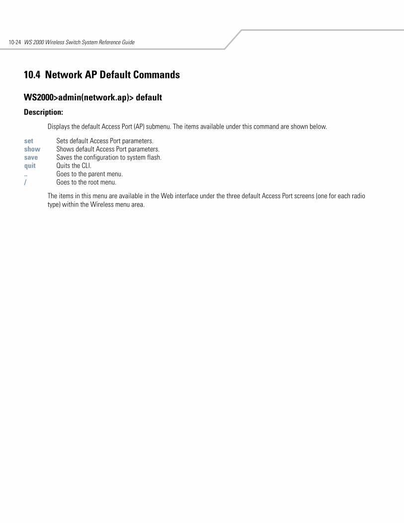
WS 2000 Wireless Switch System Reference Guide10-24
10.4 Network AP Default Commands
WS2000>admin(network.ap)> default
Description:
Displays the default Access Port (AP) submenu. The items available under this command are shown below.
The items in this menu are available in the Web interface under the three default Access Port screens (one for each radio type) within the Wireless menu area.
set Sets default Access Port parameters. show Shows default Access Port parameters. save Saves the configuration to system flash.quit Quits the CLI. .. Goes to the parent menu./ Goes to the root menu.
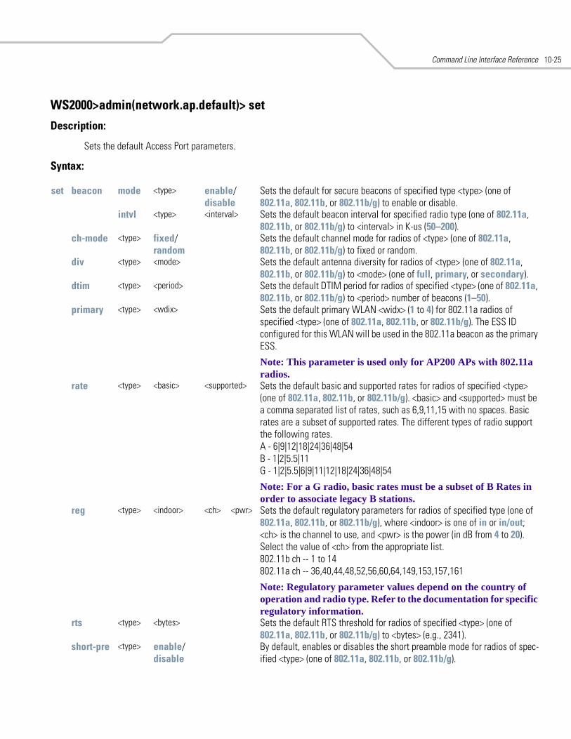
Command Line Interface Reference 10-25
WS2000>admin(network.ap.default)> set
Description:
Sets the default Access Port parameters.
Syntax:
set beacon mode <type> enable/disable
Sets the default for secure beacons of specified type <type> (one of 802.11a, 802.11b, or 802.11b/g) to enable or disable.
intvl <type> <interval> Sets the default beacon interval for specified radio type (one of 802.11a, 802.11b, or 802.11b/g) to <interval> in K-us (50–200).
ch-mode <type> fixed/random
Sets the default channel mode for radios of <type> (one of 802.11a, 802.11b, or 802.11b/g) to fixed or random.
div <type> <mode> Sets the default antenna diversity for radios of <type> (one of 802.11a, 802.11b, or 802.11b/g) to <mode> (one of full, primary, or secondary).
dtim <type> <period> Sets the default DTIM period for radios of specified <type> (one of 802.11a, 802.11b, or 802.11b/g) to <period> number of beacons (1–50).
primary <type> <wdix> Sets the default primary WLAN <widx> (1 to 4) for 802.11a radios of specified <type> (one of 802.11a, 802.11b, or 802.11b/g). The ESS ID configured for this WLAN will be used in the 802.11a beacon as the primary ESS.
Note: This parameter is used only for AP200 APs with 802.11a radios.
rate <type> <basic> <supported> Sets the default basic and supported rates for radios of specified <type> (one of 802.11a, 802.11b, or 802.11b/g). <basic> and <supported> must be a comma separated list of rates, such as 6,9,11,15 with no spaces. Basic rates are a subset of supported rates. The different types of radio support the following rates. A - 6|9|12|18|24|36|48|54 B - 1|2|5.5|11 G - 1|2|5.5|6|9|11|12|18|24|36|48|54
Note: For a G radio, basic rates must be a subset of B Rates in order to associate legacy B stations.
reg <type> <indoor> <ch> <pwr> Sets the default regulatory parameters for radios of specified type (one of 802.11a, 802.11b, or 802.11b/g), where <indoor> is one of in or in/out; <ch> is the channel to use, and <pwr> is the power (in dB from 4 to 20). Select the value of <ch> from the appropriate list. 802.11b ch -- 1 to 14 802.11a ch -- 36,40,44,48,52,56,60,64,149,153,157,161
Note: Regulatory parameter values depend on the country of operation and radio type. Refer to the documentation for specific regulatory information.
rts <type> <bytes> Sets the default RTS threshold for radios of specified <type> (one of 802.11a, 802.11b, or 802.11b/g) to <bytes> (e.g., 2341).
short-pre <type> enable/disable
By default, enables or disables the short preamble mode for radios of spec-ified <type> (one of 802.11a, 802.11b, or 802.11b/g).
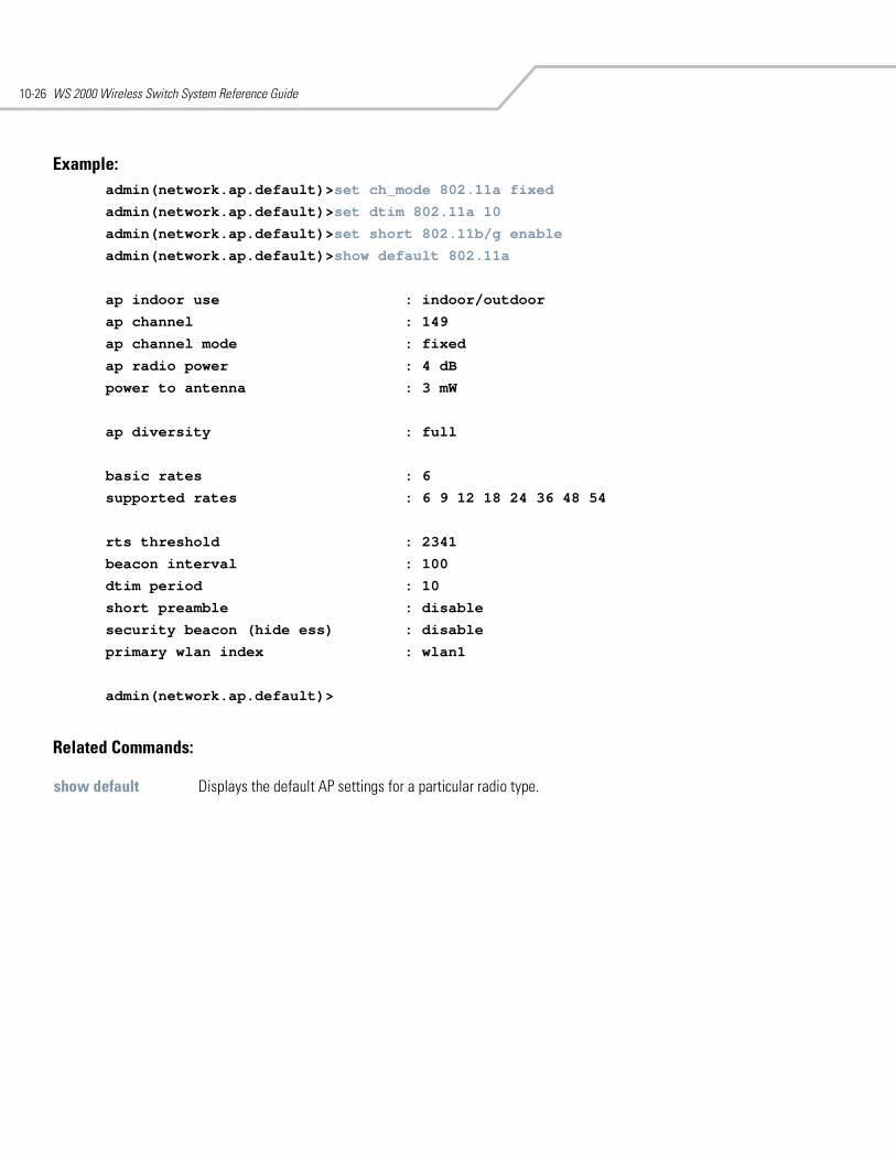
WS 2000 Wireless Switch System Reference Guide10-26
Example: admin(network.ap.default)>set ch_mode 802.11a fixed
admin(network.ap.default)>set dtim 802.11a 10
admin(network.ap.default)>set short 802.11b/g enable
admin(network.ap.default)>show default 802.11a
ap indoor use : indoor/outdoor
ap channel : 149
ap channel mode : fixed
ap radio power : 4 dB
power to antenna : 3 mW
ap diversity : full
basic rates : 6
supported rates : 6 9 12 18 24 36 48 54
rts threshold : 2341
beacon interval : 100
dtim period : 10
short preamble : disable
security beacon (hide ess) : disable
primary wlan index : wlan1
admin(network.ap.default)>
Related Commands:
show default Displays the default AP settings for a particular radio type.
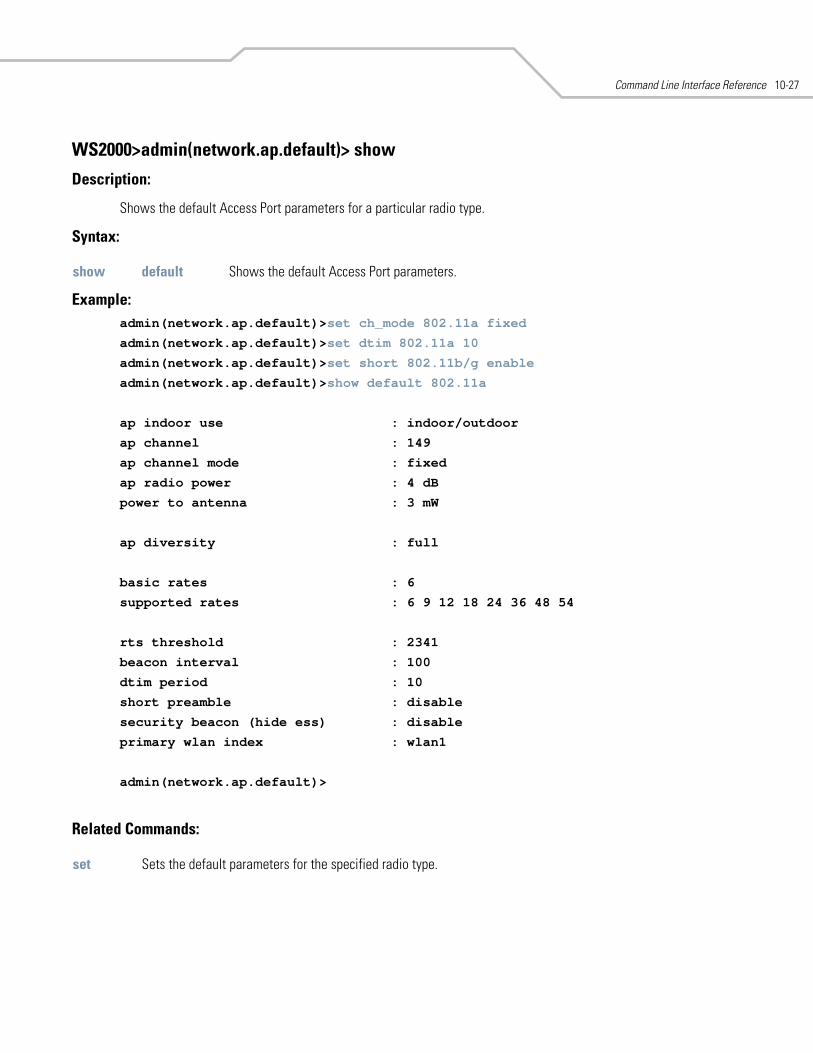
Command Line Interface Reference 10-27
WS2000>admin(network.ap.default)> show
Description:
Shows the default Access Port parameters for a particular radio type.
Syntax:
Example: admin(network.ap.default)>set ch_mode 802.11a fixed
admin(network.ap.default)>set dtim 802.11a 10
admin(network.ap.default)>set short 802.11b/g enable
admin(network.ap.default)>show default 802.11a
ap indoor use : indoor/outdoor
ap channel : 149
ap channel mode : fixed
ap radio power : 4 dB
power to antenna : 3 mW
ap diversity : full
basic rates : 6
supported rates : 6 9 12 18 24 36 48 54
rts threshold : 2341
beacon interval : 100
dtim period : 10
short preamble : disable
security beacon (hide ess) : disable
primary wlan index : wlan1
admin(network.ap.default)>
Related Commands:
show default Shows the default Access Port parameters.
set Sets the default parameters for the specified radio type.
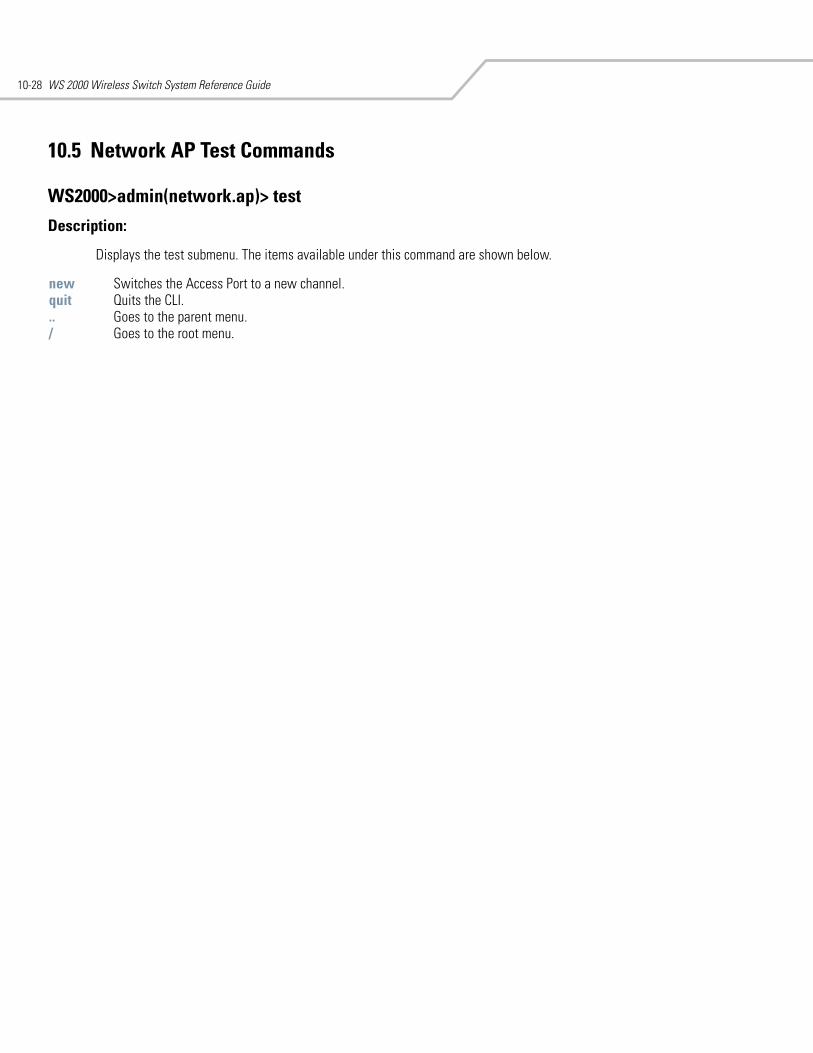
WS 2000 Wireless Switch System Reference Guide10-28
10.5 Network AP Test Commands
WS2000>admin(network.ap)> test
Description:
Displays the test submenu. The items available under this command are shown below.
new Switches the Access Port to a new channel.quit Quits the CLI. .. Goes to the parent menu./ Goes to the root menu.
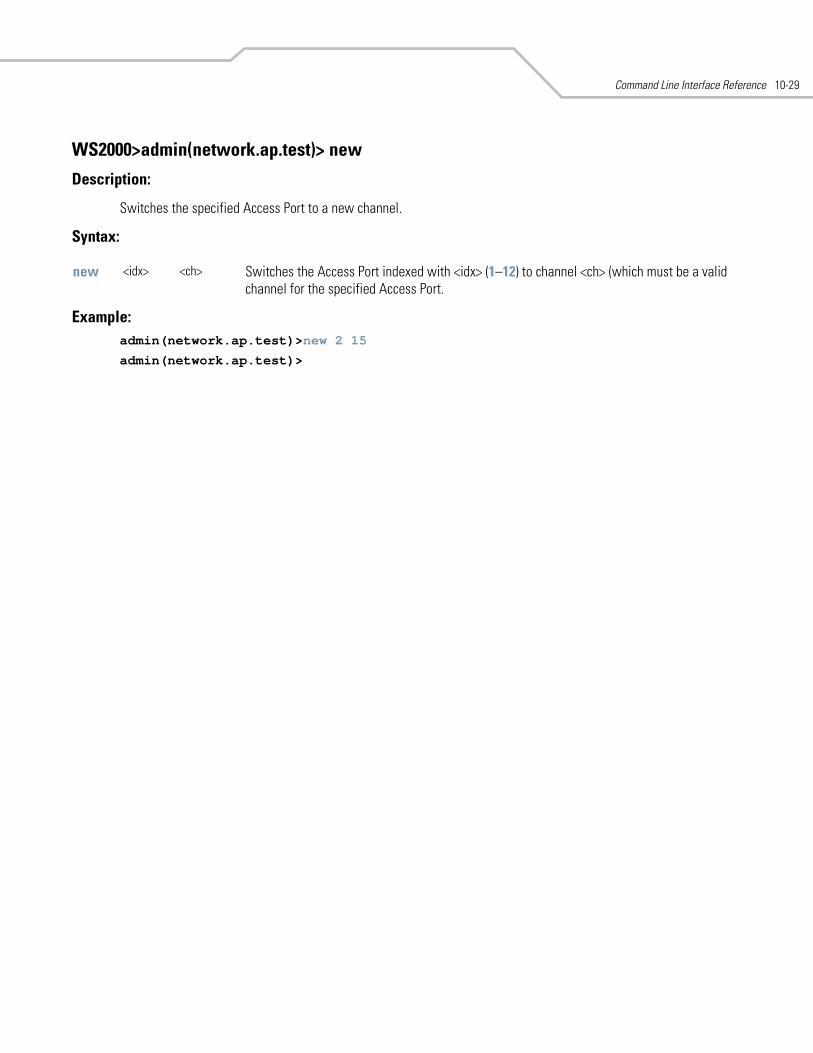
Command Line Interface Reference 10-29
WS2000>admin(network.ap.test)> new
Description:
Switches the specified Access Port to a new channel.
Syntax:
Example: admin(network.ap.test)>new 2 15
admin(network.ap.test)>
new <idx> <ch> Switches the Access Port indexed with <idx> (1–12) to channel <ch> (which must be a valid channel for the specified Access Port.
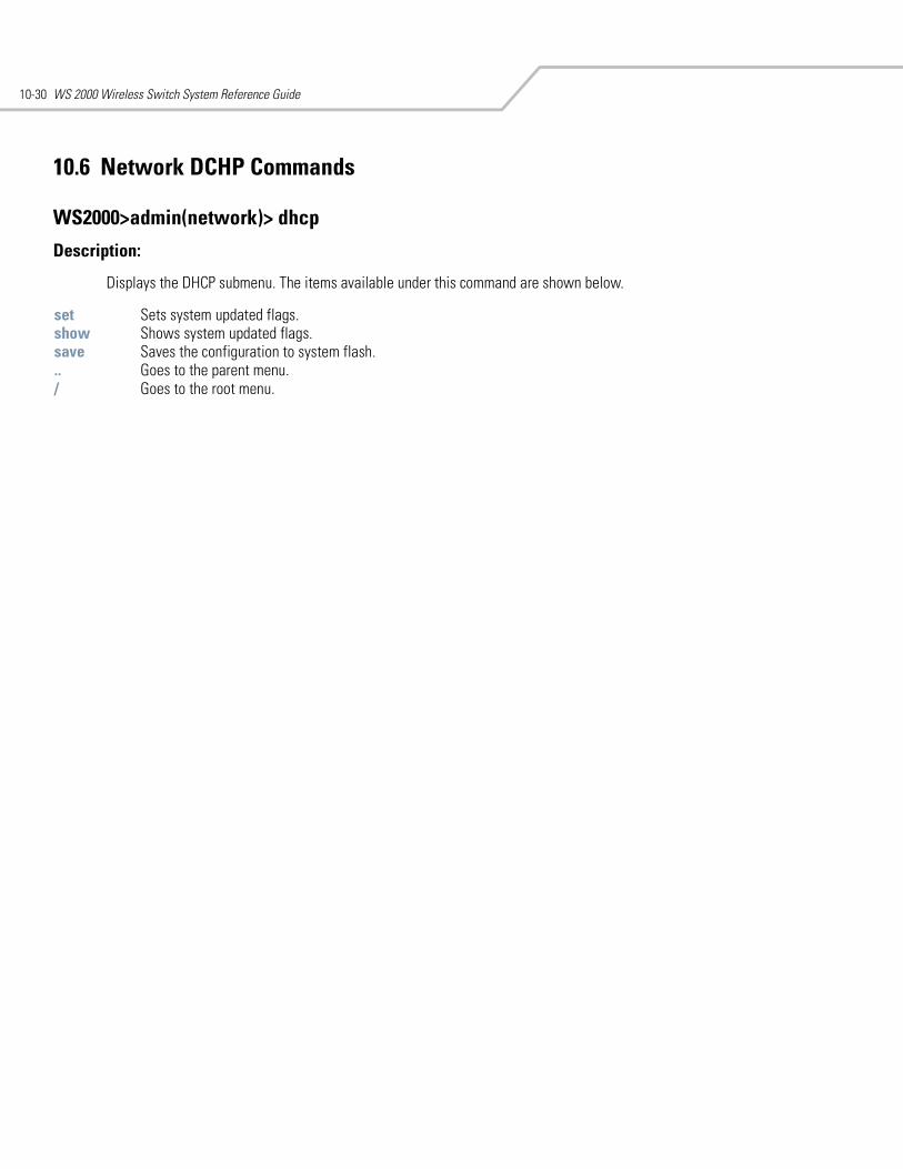
WS 2000 Wireless Switch System Reference Guide10-30
10.6 Network DCHP Commands
WS2000>admin(network)> dhcp
Description:
Displays the DHCP submenu. The items available under this command are shown below.
set Sets system updated flags. show Shows system updated flags. save Saves the configuration to system flash... Goes to the parent menu./ Goes to the root menu.
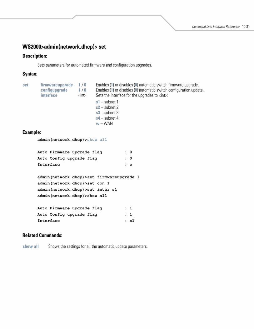
Command Line Interface Reference 10-31
WS2000>admin(network.dhcp)> set
Description:
Sets parameters for automated firmware and configuration upgrades.
Syntax:
Example: admin(network.dhcp)>show all
Auto Firmware upgrade flag : 0
Auto Config upgrade flag : 0
Interface : w
admin(network.dhcp)>set firmwareupgrade 1
admin(network.dhcp)>set con 1
admin(network.dhcp)>set inter s1
admin(network.dhcp)>show all
Auto Firmware upgrade flag : 1
Auto Config upgrade flag : 1
Interface : s1
Related Commands:
set firmwareupgrade 1 / 0 Enables (1) or disables (0) automatic switch firmware upgrade.configupgrade 1 / 0 Enables (1) or disables (0) automatic switch configuration update.interface <int> Sets the interface for the upgrades to <int>:
s1 – subnet 1s2 – subnet 2s3 – subnet 3s4 – subnet 4w – WAN
show all Shows the settings for all the automatic update parameters.
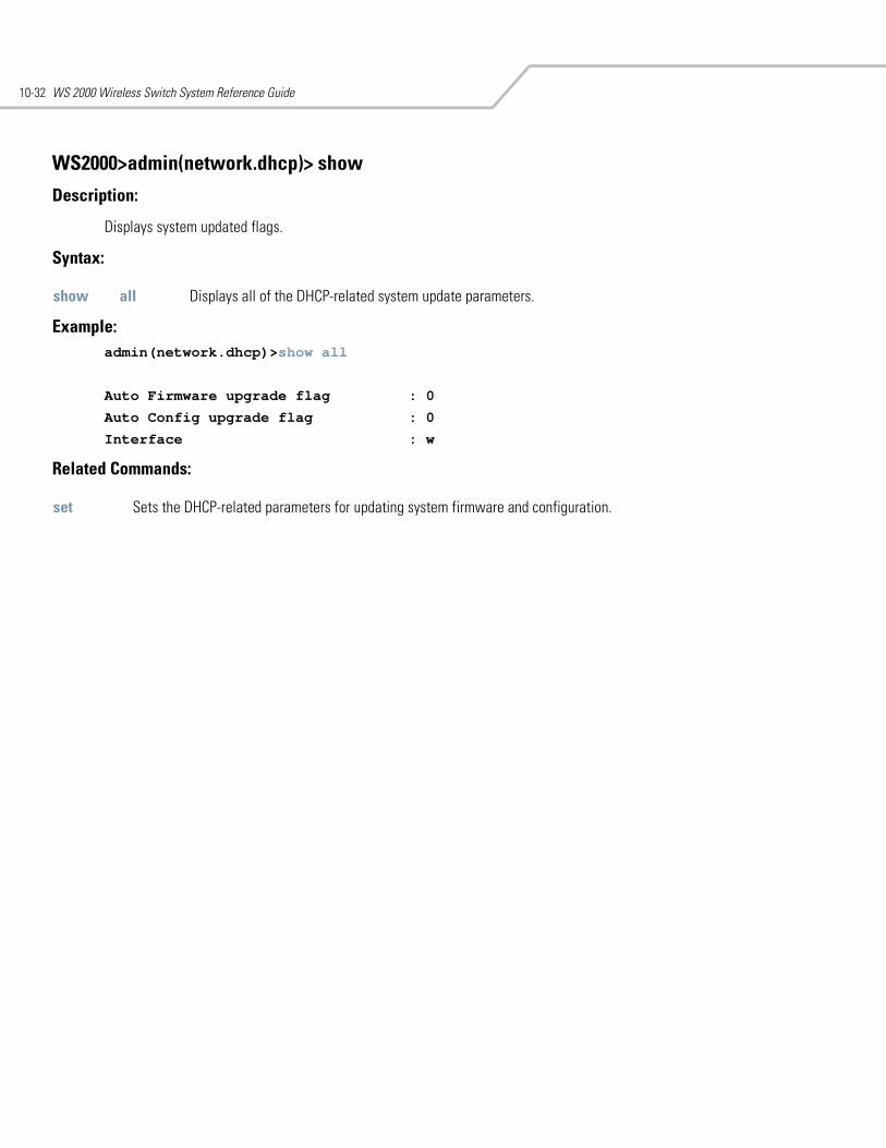
WS 2000 Wireless Switch System Reference Guide10-32
WS2000>admin(network.dhcp)> show
Description:
Displays system updated flags.
Syntax:
Example: admin(network.dhcp)>show all
Auto Firmware upgrade flag : 0
Auto Config upgrade flag : 0
Interface : w
Related Commands:
show all Displays all of the DHCP-related system update parameters.
set Sets the DHCP-related parameters for updating system firmware and configuration.
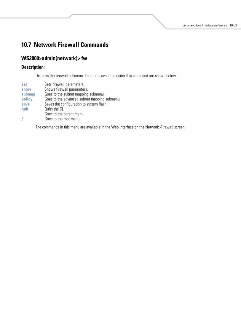
Command Line Interface Reference 10-33
10.7 Network Firewall Commands
WS2000>admin(network)> fw
Description:
Displays the firewall submenu. The items available under this command are shown below.
The commands in this menu are available in the Web interface on the Network>Firewall screen.
set Sets firewall parameters. show Shows firewall parameters. submap Goes to the subnet mapping submenu. policy Goes to the advanced subnet mapping submenu. save Saves the configuration to system flash.quit Quits the CLI. .. Goes to the parent menu./ Goes to the root menu.
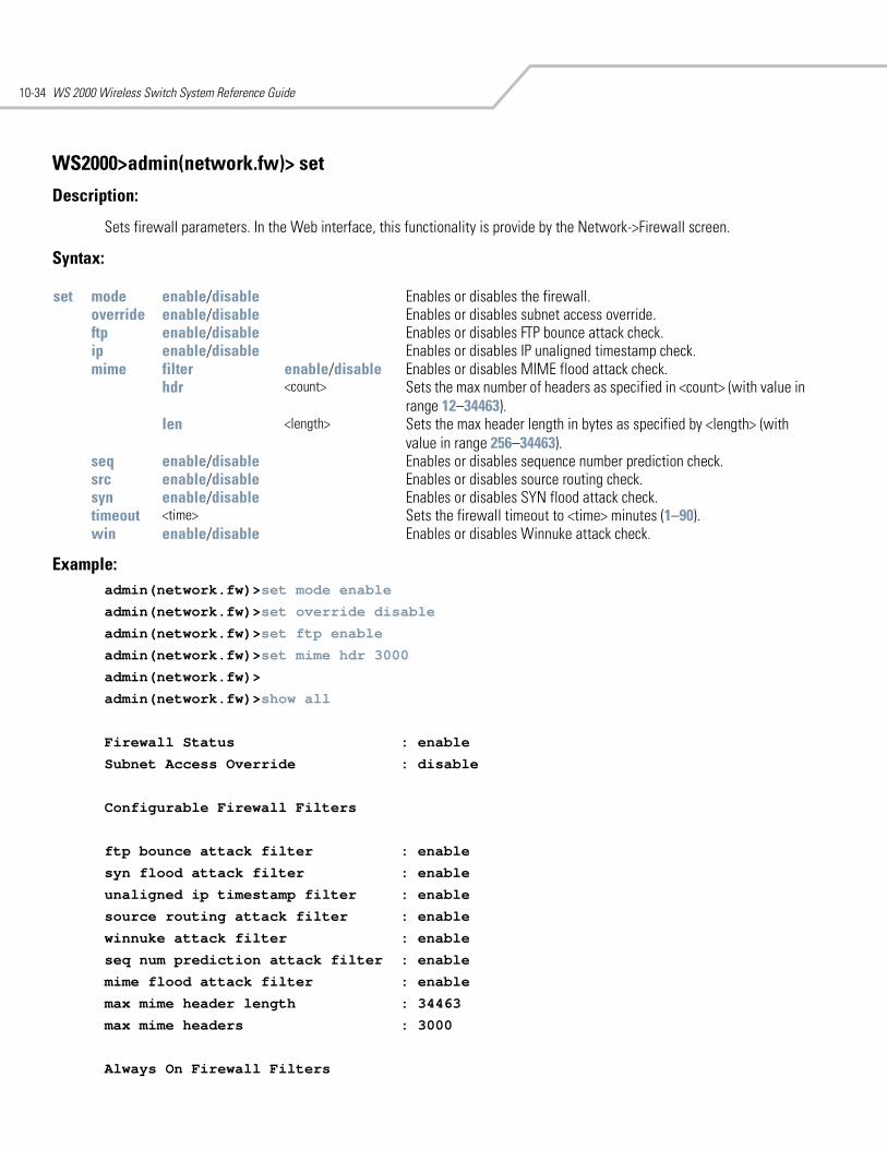
WS 2000 Wireless Switch System Reference Guide10-34
WS2000>admin(network.fw)> set
Description:
Sets firewall parameters. In the Web interface, this functionality is provide by the Network->Firewall screen.
Syntax:
Example: admin(network.fw)>set mode enable
admin(network.fw)>set override disable
admin(network.fw)>set ftp enable
admin(network.fw)>set mime hdr 3000
admin(network.fw)>
admin(network.fw)>show all
Firewall Status : enable
Subnet Access Override : disable
Configurable Firewall Filters
ftp bounce attack filter : enable
syn flood attack filter : enable
unaligned ip timestamp filter : enable
source routing attack filter : enable
winnuke attack filter : enable
seq num prediction attack filter : enable
mime flood attack filter : enable
max mime header length : 34463
max mime headers : 3000
Always On Firewall Filters
set mode enable/disable Enables or disables the firewall.override enable/disable Enables or disables subnet access override.ftp enable/disable Enables or disables FTP bounce attack check.ip enable/disable Enables or disables IP unaligned timestamp check.mime filter enable/disable Enables or disables MIME flood attack check.
hdr <count> Sets the max number of headers as specified in <count> (with value in range 12–34463).
len <length> Sets the max header length in bytes as specified by <length> (with value in range 256–34463).
seq enable/disable Enables or disables sequence number prediction check.src enable/disable Enables or disables source routing check.syn enable/disable Enables or disables SYN flood attack check.timeout <time> Sets the firewall timeout to <time> minutes (1–90).win enable/disable Enables or disables Winnuke attack check.
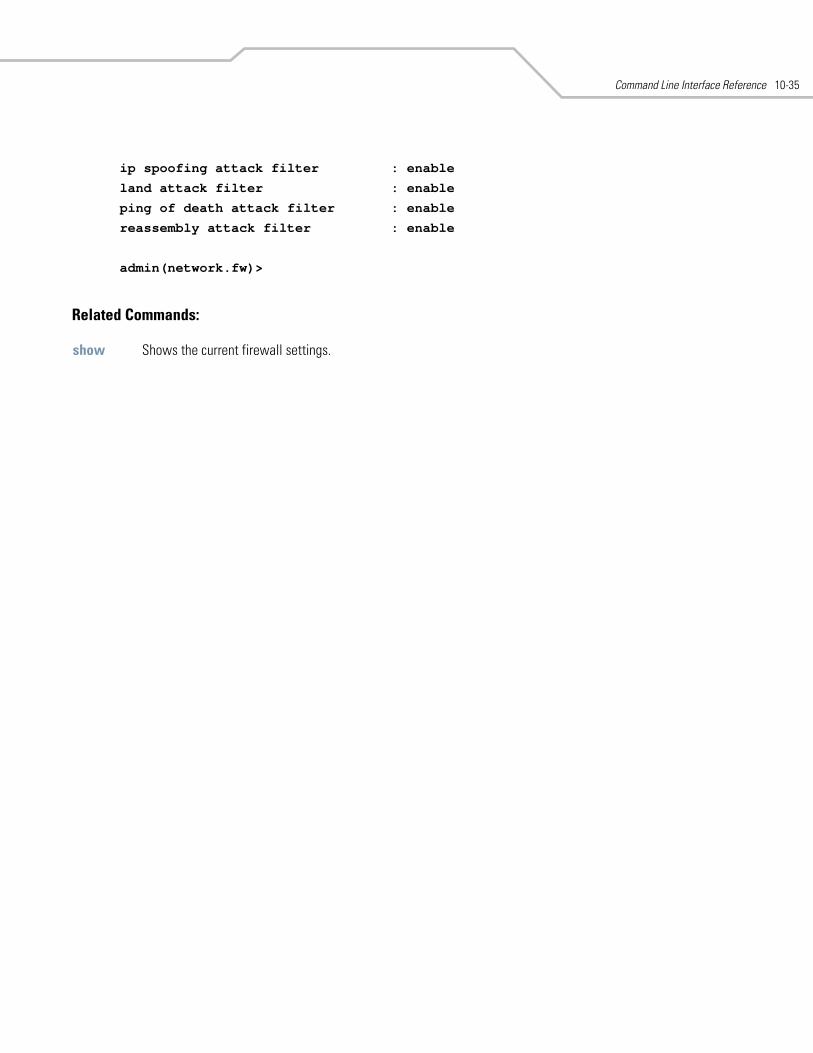
Command Line Interface Reference 10-35
ip spoofing attack filter : enable
land attack filter : enable
ping of death attack filter : enable
reassembly attack filter : enable
admin(network.fw)>
Related Commands:
show Shows the current firewall settings.
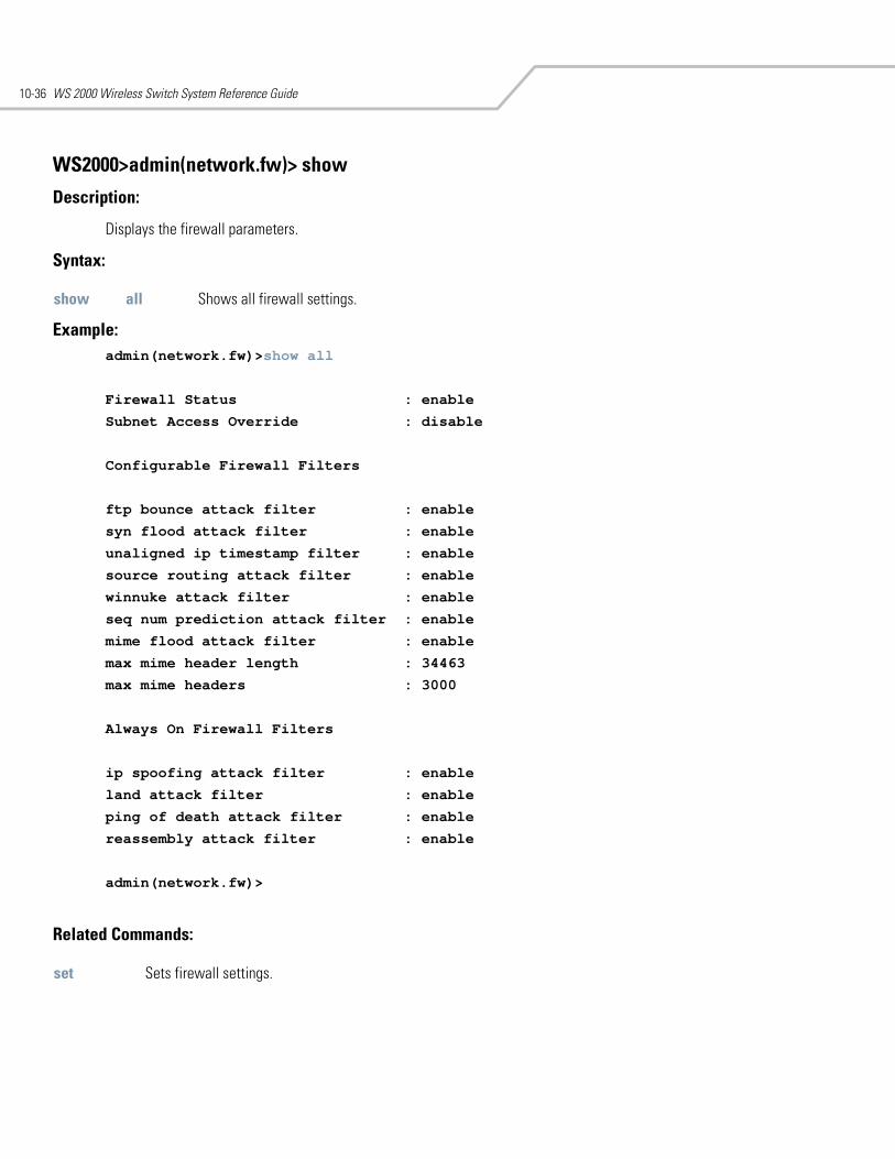
WS 2000 Wireless Switch System Reference Guide10-36
WS2000>admin(network.fw)> show
Description:
Displays the firewall parameters.
Syntax:
Example:admin(network.fw)>show all
Firewall Status : enable
Subnet Access Override : disable
Configurable Firewall Filters
ftp bounce attack filter : enable
syn flood attack filter : enable
unaligned ip timestamp filter : enable
source routing attack filter : enable
winnuke attack filter : enable
seq num prediction attack filter : enable
mime flood attack filter : enable
max mime header length : 34463
max mime headers : 3000
Always On Firewall Filters
ip spoofing attack filter : enable
land attack filter : enable
ping of death attack filter : enable
reassembly attack filter : enable
admin(network.fw)>
Related Commands:
show all Shows all firewall settings.
set Sets firewall settings.
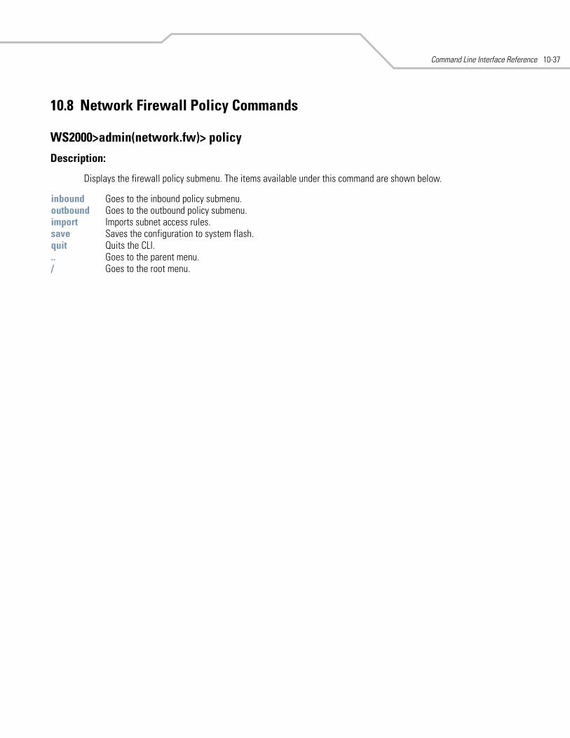
Command Line Interface Reference 10-37
10.8 Network Firewall Policy Commands
WS2000>admin(network.fw)> policy
Description:
Displays the firewall policy submenu. The items available under this command are shown below.
inbound Goes to the inbound policy submenu.outbound Goes to the outbound policy submenu.import Imports subnet access rules.save Saves the configuration to system flash.quit Quits the CLI. .. Goes to the parent menu./ Goes to the root menu.
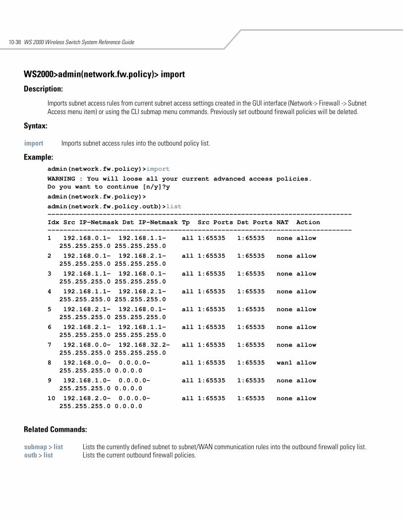
WS 2000 Wireless Switch System Reference Guide10-38
WS2000>admin(network.fw.policy)> import
Description:
Imports subnet access rules from current subnet access settings created in the GUI interface (Network-> Firewall -> Subnet Access menu item) or using the CLI submap menu commands. Previously set outbound firewall policies will be deleted.
Syntax:
Example: admin(network.fw.policy)>import
WARNING : You will loose all your current advanced access policies.Do you want to continue [n/y]?y
admin(network.fw.policy)>
admin(network.fw.policy.outb)>list-----------------------------------------------------------------------------Idx Src IP-Netmask Dst IP-Netmask Tp Src Ports Dst Ports NAT Action-----------------------------------------------------------------------------1 192.168.0.1- 192.168.1.1- all 1:65535 1:65535 none allow
255.255.255.0 255.255.255.0
2 192.168.0.1- 192.168.2.1- all 1:65535 1:65535 none allow255.255.255.0 255.255.255.0
3 192.168.1.1- 192.168.0.1- all 1:65535 1:65535 none allow255.255.255.0 255.255.255.0
4 192.168.1.1- 192.168.2.1- all 1:65535 1:65535 none allow255.255.255.0 255.255.255.0
5 192.168.2.1- 192.168.0.1- all 1:65535 1:65535 none allow255.255.255.0 255.255.255.0
6 192.168.2.1- 192.168.1.1- all 1:65535 1:65535 none allow255.255.255.0 255.255.255.0
7 192.168.0.0- 192.168.32.2- all 1:65535 1:65535 none allow255.255.255.0 255.255.255.0
8 192.168.0.0- 0.0.0.0- all 1:65535 1:65535 wan1 allow255.255.255.0 0.0.0.0
9 192.168.1.0- 0.0.0.0- all 1:65535 1:65535 none allow255.255.255.0 0.0.0.0
10 192.168.2.0- 0.0.0.0- all 1:65535 1:65535 none allow255.255.255.0 0.0.0.0
Related Commands:
import Imports subnet access rules into the outbound policy list.
submap > list Lists the currently defined subnet to subnet/WAN communication rules into the outbound firewall policy list. outb > list Lists the current outbound firewall policies.
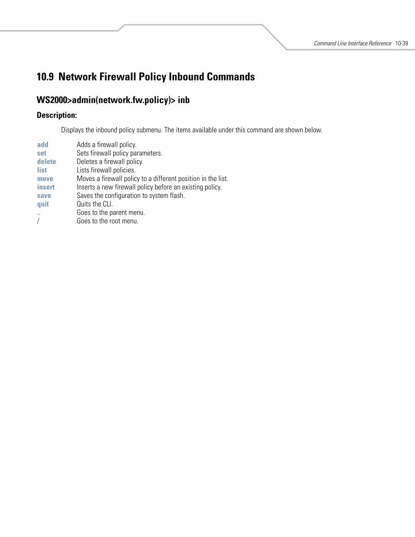
Command Line Interface Reference 10-39
10.9 Network Firewall Policy Inbound Commands
WS2000>admin(network.fw.policy)> inb
Description:
Displays the inbound policy submenu. The items available under this command are shown below.
add Adds a firewall policy.set Sets firewall policy parameters.delete Deletes a firewall policy.list Lists firewall policies.move Moves a firewall policy to a different position in the list.insert Inserts a new firewall policy before an existing policy.save Saves the configuration to system flash.quit Quits the CLI. .. Goes to the parent menu./ Goes to the root menu.
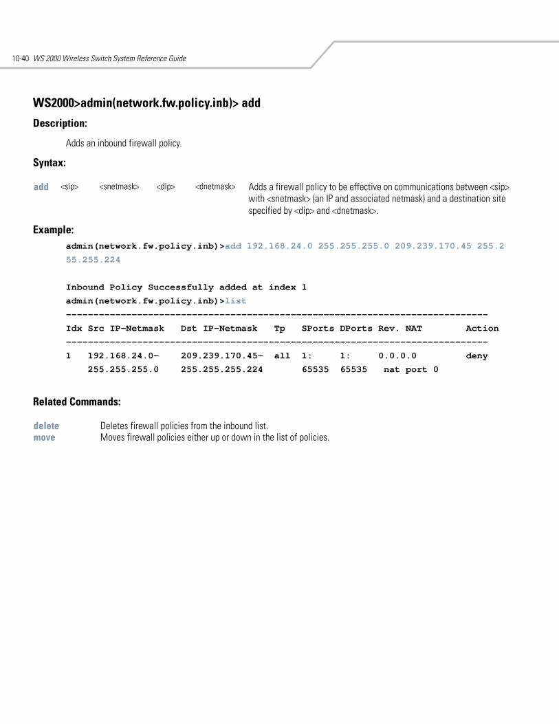
WS 2000 Wireless Switch System Reference Guide10-40
WS2000>admin(network.fw.policy.inb)> add
Description:
Adds an inbound firewall policy.
Syntax:
Example: admin(network.fw.policy.inb)>add 192.168.24.0 255.255.255.0 209.239.170.45 255.2
55.255.224
Inbound Policy Successfully added at index 1
admin(network.fw.policy.inb)>list
-----------------------------------------------------------------------------
Idx Src IP-Netmask Dst IP-Netmask Tp SPorts DPorts Rev. NAT Action
-----------------------------------------------------------------------------
1 192.168.24.0- 209.239.170.45- all 1: 1: 0.0.0.0 deny
255.255.255.0 255.255.255.224 65535 65535 nat port 0
Related Commands:
add <sip> <snetmask> <dip> <dnetmask> Adds a firewall policy to be effective on communications between <sip> with <snetmask> (an IP and associated netmask) and a destination site specified by <dip> and <dnetmask>.
delete Deletes firewall policies from the inbound list.move Moves firewall policies either up or down in the list of policies.
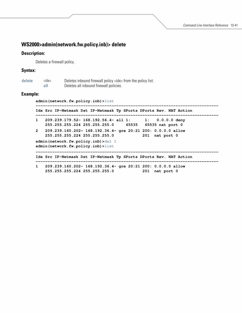
Command Line Interface Reference 10-41
WS2000>admin(network.fw.policy.inb)> delete
Description:
Deletes a firewall policy.
Syntax:
Example: admin(network.fw.policy.inb)>list-----------------------------------------------------------------------------Idx Src IP-Netmask Dst IP-Netmask Tp SPorts DPorts Rev. NAT Action-----------------------------------------------------------------------------1 209.239.179.52- 168.192.56.4- all 1: 1: 0.0.0.0 deny
255.255.255.224 255.255.255.0 65535 65535 nat port 0
2 209.239.160.202- 168.192.36.4- gre 20:21 200: 0.0.0.0 allow255.255.255.224 255.255.255.0 201 nat port 0
admin(network.fw.policy.inb)>del 1admin(network.fw.policy.inb)>list
-----------------------------------------------------------------------------Idx Src IP-Netmask Dst IP-Netmask Tp SPorts DPorts Rev. NAT Action-----------------------------------------------------------------------------1 209.239.160.202- 168.192.36.4- gre 20:21 200: 0.0.0.0 allow
255.255.255.224 255.255.255.0 201 nat port 0
delete <idx> Deletes inbound firewall policy <idx> from the policy list. all Deletes all inbound firewall policies.
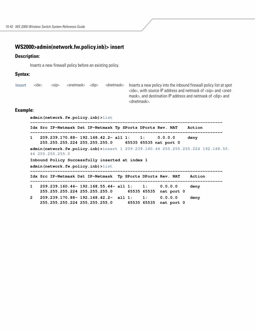
WS 2000 Wireless Switch System Reference Guide10-42
WS2000>admin(network.fw.policy.inb)> insert
Description:
Inserts a new firewall policy before an existing policy.
Syntax:
Example:admin(network.fw.policy.inb)>list-----------------------------------------------------------------------------Idx Src IP-Netmask Dst IP-Netmask Tp SPorts DPorts Rev. NAT Action-----------------------------------------------------------------------------1 209.239.170.88- 192.168.42.2- all 1: 1: 0.0.0.0 deny
255.255.255.224 255.255.255.0 65535 65535 nat port 0
admin(network.fw.policy.inb)>insert 1 209.239.160.44 255.255.255.224 192.168.55.44 255.255.255.0
Inbound Policy Successfully inserted at index 1
admin(network.fw.policy.inb)>list-----------------------------------------------------------------------------Idx Src IP-Netmask Dst IP-Netmask Tp SPorts DPorts Rev. NAT Action-----------------------------------------------------------------------------1 209.239.160.44- 192.168.55.44- all 1: 1: 0.0.0.0 deny
255.255.255.224 255.255.255.0 65535 65535 nat port 0
2 209.239.170.88- 192.168.42.2- all 1: 1: 0.0.0.0 deny255.255.255.224 255.255.255.0 65535 65535 nat port 0
insert <idx> <sip> <snetmask> <dip> <dnetmask> Inserts a new policy into the inbound firewall policy list at spot <idx>, with source IP address and netmask of <sip> and <snet-mask>, and destination IP address and netmask of <dip> and <dnetmask>.
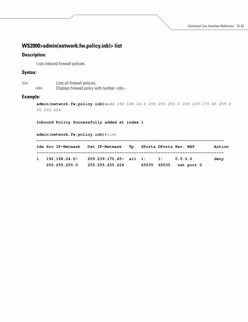
Command Line Interface Reference 10-43
WS2000>admin(network.fw.policy.inb)> list
Description:
Lists inbound firewall policies.
Syntax:
Example: admin(network.fw.policy.inb)>add 192.168.24.0 255.255.255.0 209.239.170.45 255.2
55.255.224
Inbound Policy Successfully added at index 1
admin(network.fw.policy.inb)>list
-----------------------------------------------------------------------------
Idx Src IP-Netmask Dst IP-Netmask Tp SPorts DPorts Rev. NAT Action
-----------------------------------------------------------------------------
1 192.168.24.0- 209.239.170.45- all 1: 1: 0.0.0.0 deny
255.255.255.0 255.255.255.224 65535 65535 nat port 0
list Lists all firewall policies. <idx> Displays firewall policy with number <idx>.
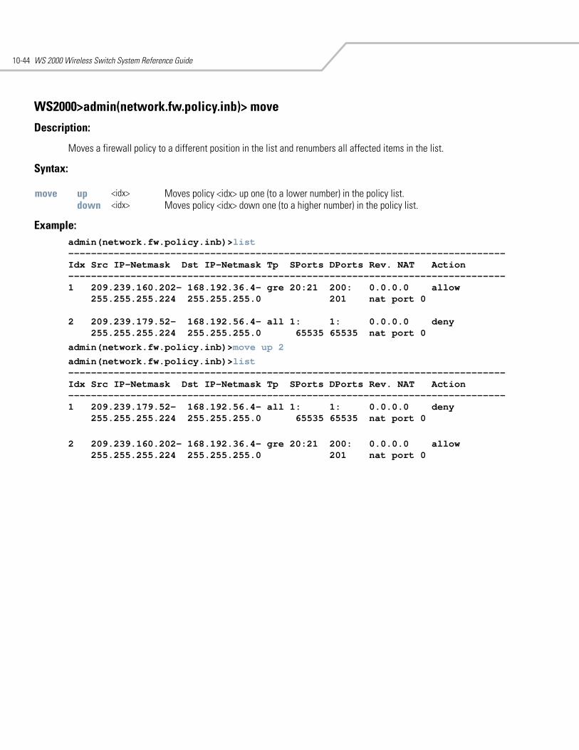
WS 2000 Wireless Switch System Reference Guide10-44
WS2000>admin(network.fw.policy.inb)> move
Description:
Moves a firewall policy to a different position in the list and renumbers all affected items in the list.
Syntax:
Example:admin(network.fw.policy.inb)>list-----------------------------------------------------------------------------Idx Src IP-Netmask Dst IP-Netmask Tp SPorts DPorts Rev. NAT Action-----------------------------------------------------------------------------1 209.239.160.202- 168.192.36.4- gre 20:21 200: 0.0.0.0 allow
255.255.255.224 255.255.255.0 201 nat port 0
2 209.239.179.52- 168.192.56.4- all 1: 1: 0.0.0.0 deny255.255.255.224 255.255.255.0 65535 65535 nat port 0
admin(network.fw.policy.inb)>move up 2
admin(network.fw.policy.inb)>list-----------------------------------------------------------------------------Idx Src IP-Netmask Dst IP-Netmask Tp SPorts DPorts Rev. NAT Action-----------------------------------------------------------------------------1 209.239.179.52- 168.192.56.4- all 1: 1: 0.0.0.0 deny
255.255.255.224 255.255.255.0 65535 65535 nat port 0
2 209.239.160.202- 168.192.36.4- gre 20:21 200: 0.0.0.0 allow255.255.255.224 255.255.255.0 201 nat port 0
move up <idx> Moves policy <idx> up one (to a lower number) in the policy list.down <idx> Moves policy <idx> down one (to a higher number) in the policy list.
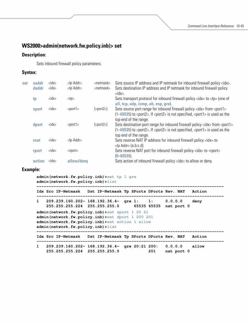
Command Line Interface Reference 10-45
WS2000>admin(network.fw.policy.inb)> set
Description:
Sets inbound firewall policy parameters.
Syntax:
Example: admin(network.fw.policy.inb)>set tp 1 greadmin(network.fw.policy.inb)>list-----------------------------------------------------------------------------Idx Src IP-Netmask Dst IP-Netmask Tp SPorts DPorts Rev. NAT Action-----------------------------------------------------------------------------1 209.239.160.202- 168.192.36.4- gre 1: 1: 0.0.0.0 deny
255.255.255.224 255.255.255.0 65535 65535 nat port 0
admin(network.fw.policy.inb)>set sport 1 20 21admin(network.fw.policy.inb)>set dport 1 200 201admin(network.fw.policy.inb)>set action 1 allowadmin(network.fw.policy.inb)>list-----------------------------------------------------------------------------Idx Src IP-Netmask Dst IP-Netmask Tp SPorts DPorts Rev. NAT Action-----------------------------------------------------------------------------1 209.239.160.202- 168.192.36.4- gre 20:21 200: 0.0.0.0 allow
255.255.255.224 255.255.255.0 201 nat port 0
set saddr <idx> <Ip Addr> <netmask> Sets source IP address and IP netmask for inbound firewall policy <idx>.daddr <idx> <Ip Addr> <netmask> Sets destination IP address and IP netmask for inbound firewall policy
<idx>.tp <idx> <tp> Sets transport protocol for inbound firewall policy <idx> to <tp> (one of
all, tcp, udp, icmp, ah, esp, gre).sport <idx> <port1> [<port2>] Sets source port range for inbound firewall policy <idx> from <port1>
(1–65535) to <port2>. If <port2> is not specified, <port1> is used as the top end of the range.
dport <idx> <port1> [<port2>] Sets destination port range for inbound firewall policy <idx> from <port1> (1–65535) to <port2>. If <port2> is not specified, <port1> is used as the top end of the range.
rnat <idx> <Ip Addr> Sets reverse NAT IP address for inbound firewall policy <idx> to<Ip Addr> (a.b.c.d).
rport <idx> <rport> Sets reverse NAT port for inbound firewall policy <idx> to <rport>(0–65535).
action <idx> allow/deny Sets action of inbound firewall policy <idx> to allow or deny.
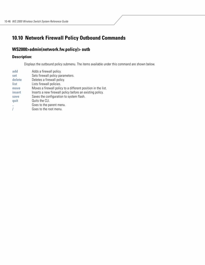
WS 2000 Wireless Switch System Reference Guide10-46
10.10 Network Firewall Policy Outbound Commands
WS2000>admin(network.fw.policy)> outb
Description:
Displays the outbound policy submenu. The items available under this command are shown below.
add Adds a firewall policy.set Sets firewall policy parameters.delete Deletes a firewall policy.list Lists firewall policies.move Moves a firewall policy to a different position in the list.insert Inserts a new firewall policy before an existing policy.save Saves the configuration to system flash.quit Quits the CLI. .. Goes to the parent menu./ Goes to the root menu.
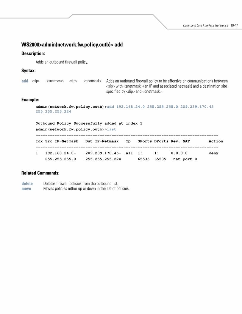
Command Line Interface Reference 10-47
WS2000>admin(network.fw.policy.outb)> add
Description:
Adds an outbound firewall policy.
Syntax:
Example: admin(network.fw.policy.outb)>add 192.168.24.0 255.255.255.0 209.239.170.45 255.255.255.224
Outbound Policy Successfully added at index 1
admin(network.fw.policy.outb)>list
-----------------------------------------------------------------------------
Idx Src IP-Netmask Dst IP-Netmask Tp SPorts DPorts Rev. NAT Action
-----------------------------------------------------------------------------
1 192.168.24.0- 209.239.170.45- all 1: 1: 0.0.0.0 deny
255.255.255.0 255.255.255.224 65535 65535 nat port 0
Related Commands:
add <sip> <snetmask> <dip> <dnetmask> Adds an outbound firewall policy to be effective on communications between <sip> with <snetmask> (an IP and associated netmask) and a destination site specified by <dip> and <dnetmask>.
delete Deletes firewall policies from the outbound list.move Moves policies either up or down in the list of policies.
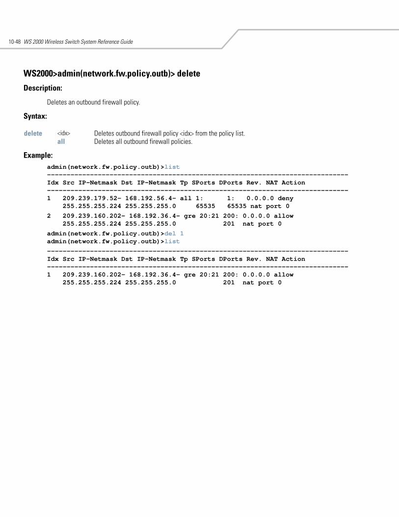
WS 2000 Wireless Switch System Reference Guide10-48
WS2000>admin(network.fw.policy.outb)> delete
Description:
Deletes an outbound firewall policy.
Syntax:
Example: admin(network.fw.policy.outb)>list-----------------------------------------------------------------------------Idx Src IP-Netmask Dst IP-Netmask Tp SPorts DPorts Rev. NAT Action-----------------------------------------------------------------------------1 209.239.179.52- 168.192.56.4- all 1: 1: 0.0.0.0 deny
255.255.255.224 255.255.255.0 65535 65535 nat port 0
2 209.239.160.202- 168.192.36.4- gre 20:21 200: 0.0.0.0 allow255.255.255.224 255.255.255.0 201 nat port 0
admin(network.fw.policy.outb)>del 1admin(network.fw.policy.outb)>list
-----------------------------------------------------------------------------Idx Src IP-Netmask Dst IP-Netmask Tp SPorts DPorts Rev. NAT Action-----------------------------------------------------------------------------1 209.239.160.202- 168.192.36.4- gre 20:21 200: 0.0.0.0 allow
255.255.255.224 255.255.255.0 201 nat port 0
delete <idx> Deletes outbound firewall policy <idx> from the policy list. all Deletes all outbound firewall policies.
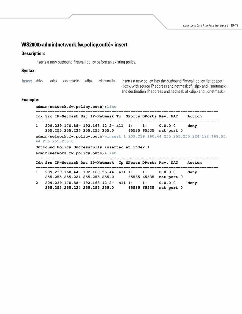
Command Line Interface Reference 10-49
WS2000>admin(network.fw.policy.outb)> insert
Description:
Inserts a new outbound firewall policy before an existing policy.
Syntax:
Example: admin(network.fw.policy.outb)>list-----------------------------------------------------------------------------Idx Src IP-Netmask Dst IP-Netmask Tp SPorts DPorts Rev. NAT Action-----------------------------------------------------------------------------1 209.239.170.88- 192.168.42.2- all 1: 1: 0.0.0.0 deny
255.255.255.224 255.255.255.0 65535 65535 nat port 0
admin(network.fw.policy.outb)>insert 1 209.239.160.44 255.255.255.224 192.168.55.44 255.255.255.0
Outbound Policy Successfully inserted at index 1
admin(network.fw.policy.outb)>list-----------------------------------------------------------------------------Idx Src IP-Netmask Dst IP-Netmask Tp SPorts DPorts Rev. NAT Action-----------------------------------------------------------------------------1 209.239.160.44- 192.168.55.44- all 1: 1: 0.0.0.0 deny
255.255.255.224 255.255.255.0 65535 65535 nat port 0
2 209.239.170.88- 192.168.42.2- all 1: 1: 0.0.0.0 deny255.255.255.224 255.255.255.0 65535 65535 nat port 0
insert <idx> <sip> <snetmask> <dip> <dnetmask> Inserts a new policy into the outbound firewall policy list at spot <idx>, with source IP address and netmask of <sip> and <snetmask>, and destination IP address and netmask of <dip> and <dnetmask>.
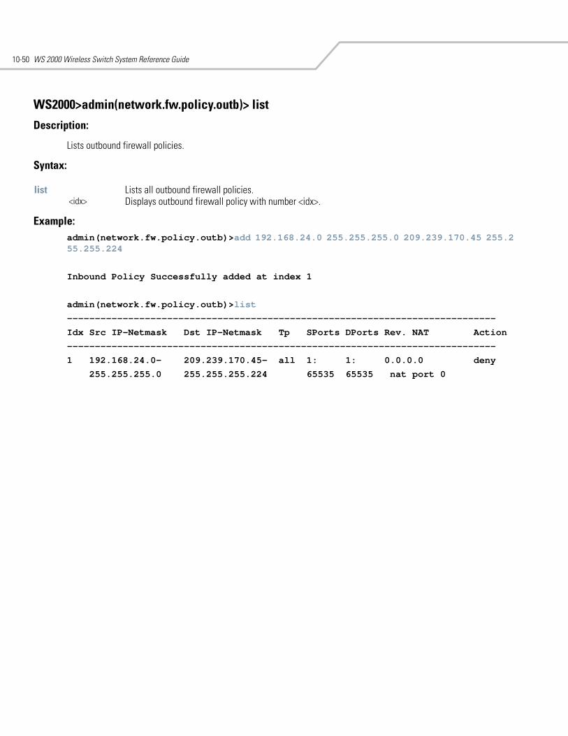
WS 2000 Wireless Switch System Reference Guide10-50
WS2000>admin(network.fw.policy.outb)> list
Description:
Lists outbound firewall policies.
Syntax:
Example: admin(network.fw.policy.outb)>add 192.168.24.0 255.255.255.0 209.239.170.45 255.2 55.255.224
Inbound Policy Successfully added at index 1
admin(network.fw.policy.outb)>list
-----------------------------------------------------------------------------
Idx Src IP-Netmask Dst IP-Netmask Tp SPorts DPorts Rev. NAT Action
-----------------------------------------------------------------------------
1 192.168.24.0- 209.239.170.45- all 1: 1: 0.0.0.0 deny
255.255.255.0 255.255.255.224 65535 65535 nat port 0
list Lists all outbound firewall policies. <idx> Displays outbound firewall policy with number <idx>.
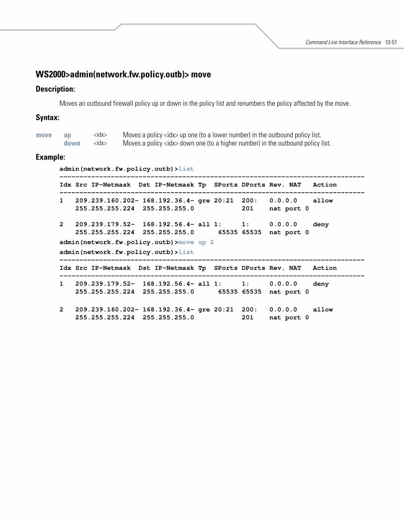
Command Line Interface Reference 10-51
WS2000>admin(network.fw.policy.outb)> move
Description:
Moves an outbound firewall policy up or down in the policy list and renumbers the policy affected by the move.
Syntax:
Example: admin(network.fw.policy.outb)>list-----------------------------------------------------------------------------Idx Src IP-Netmask Dst IP-Netmask Tp SPorts DPorts Rev. NAT Action-----------------------------------------------------------------------------1 209.239.160.202- 168.192.36.4- gre 20:21 200: 0.0.0.0 allow
255.255.255.224 255.255.255.0 201 nat port 0
2 209.239.179.52- 168.192.56.4- all 1: 1: 0.0.0.0 deny255.255.255.224 255.255.255.0 65535 65535 nat port 0
admin(network.fw.policy.outb)>move up 2
admin(network.fw.policy.outb)>list-----------------------------------------------------------------------------Idx Src IP-Netmask Dst IP-Netmask Tp SPorts DPorts Rev. NAT Action-----------------------------------------------------------------------------1 209.239.179.52- 168.192.56.4- all 1: 1: 0.0.0.0 deny
255.255.255.224 255.255.255.0 65535 65535 nat port 0
2 209.239.160.202- 168.192.36.4- gre 20:21 200: 0.0.0.0 allow255.255.255.224 255.255.255.0 201 nat port 0
move up <idx> Moves a policy <idx> up one (to a lower number) in the outbound policy list. down <idx> Moves a policy <idx> down one (to a higher number) in the outbound policy list.
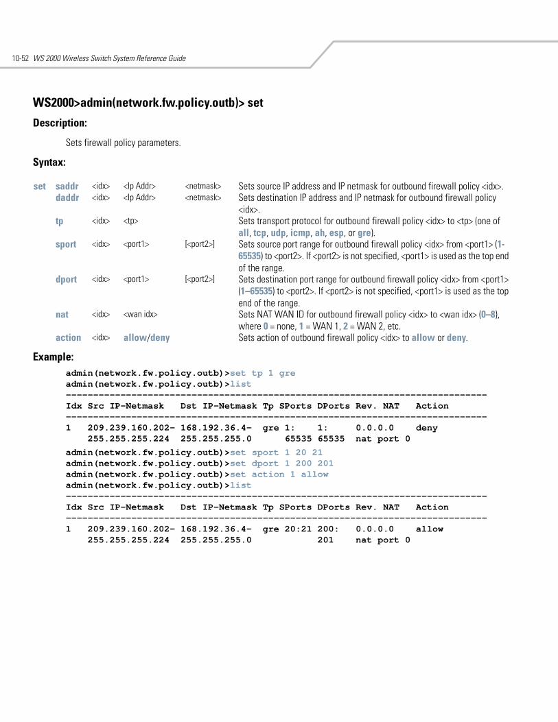
WS 2000 Wireless Switch System Reference Guide10-52
WS2000>admin(network.fw.policy.outb)> set
Description:
Sets firewall policy parameters.
Syntax:
Example: admin(network.fw.policy.outb)>set tp 1 greadmin(network.fw.policy.outb)>list-----------------------------------------------------------------------------Idx Src IP-Netmask Dst IP-Netmask Tp SPorts DPorts Rev. NAT Action-----------------------------------------------------------------------------1 209.239.160.202- 168.192.36.4- gre 1: 1: 0.0.0.0 deny
255.255.255.224 255.255.255.0 65535 65535 nat port 0
admin(network.fw.policy.outb)>set sport 1 20 21admin(network.fw.policy.outb)>set dport 1 200 201admin(network.fw.policy.outb)>set action 1 allowadmin(network.fw.policy.outb)>list-----------------------------------------------------------------------------Idx Src IP-Netmask Dst IP-Netmask Tp SPorts DPorts Rev. NAT Action-----------------------------------------------------------------------------1 209.239.160.202- 168.192.36.4- gre 20:21 200: 0.0.0.0 allow
255.255.255.224 255.255.255.0 201 nat port 0
set saddr <idx> <Ip Addr> <netmask> Sets source IP address and IP netmask for outbound firewall policy <idx>.daddr <idx> <Ip Addr> <netmask> Sets destination IP address and IP netmask for outbound firewall policy
<idx>.tp <idx> <tp> Sets transport protocol for outbound firewall policy <idx> to <tp> (one of
all, tcp, udp, icmp, ah, esp, or gre).sport <idx> <port1> [<port2>] Sets source port range for outbound firewall policy <idx> from <port1> (1-
65535) to <port2>. If <port2> is not specified, <port1> is used as the top end of the range.
dport <idx> <port1> [<port2>] Sets destination port range for outbound firewall policy <idx> from <port1> (1–65535) to <port2>. If <port2> is not specified, <port1> is used as the top end of the range.
nat <idx> <wan idx> Sets NAT WAN ID for outbound firewall policy <idx> to <wan idx> (0–8), where 0 = none, 1 = WAN 1, 2 = WAN 2, etc.
action <idx> allow/deny Sets action of outbound firewall policy <idx> to allow or deny.
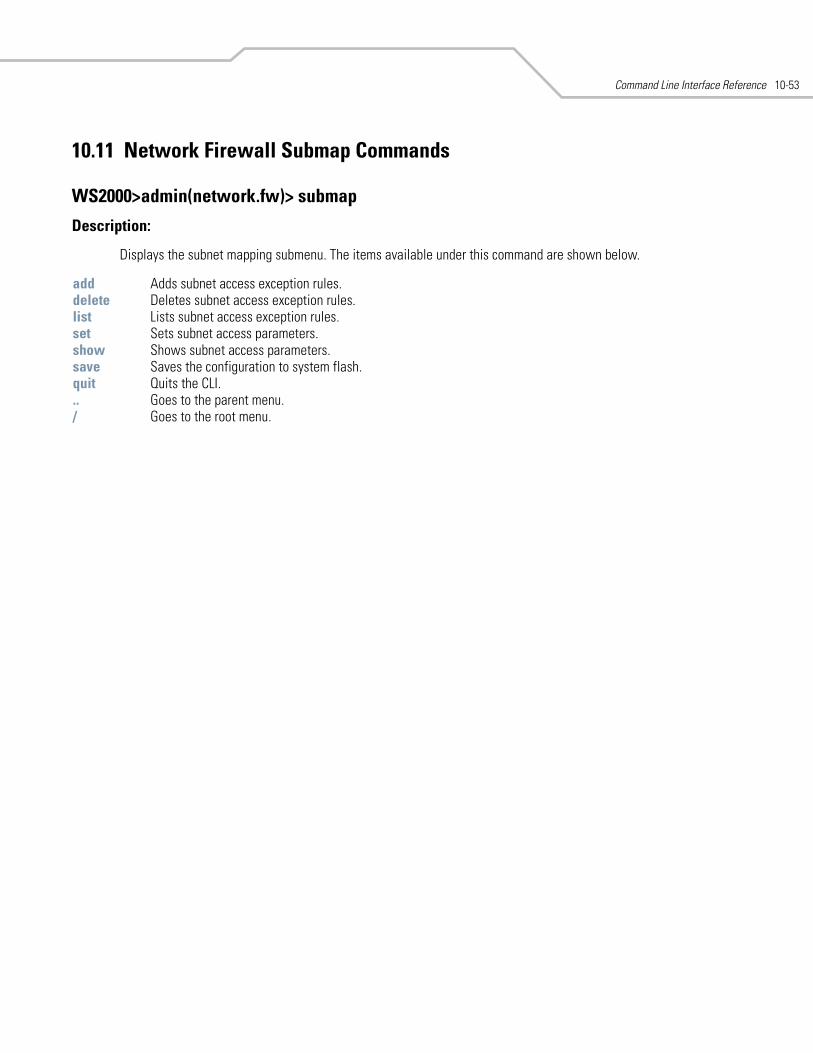
Command Line Interface Reference 10-53
10.11 Network Firewall Submap Commands
WS2000>admin(network.fw)> submap
Description:
Displays the subnet mapping submenu. The items available under this command are shown below.
add Adds subnet access exception rules. delete Deletes subnet access exception rules. list Lists subnet access exception rules. set Sets subnet access parameters. show Shows subnet access parameters. save Saves the configuration to system flash.quit Quits the CLI. .. Goes to the parent menu./ Goes to the root menu.
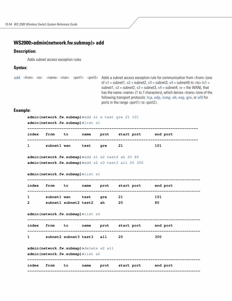
WS 2000 Wireless Switch System Reference Guide10-54
WS2000>admin(network.fw.submap)> add
Description:
Adds subnet access exception rules.
Syntax:
Example: admin(network.fw.submap)>add s1 w test gre 21 101
admin(network.fw.submap)>list s1
---------------------------------------------------------------------------
index from to name prot start port end port
---------------------------------------------------------------------------
1 subnet1 wan test gre 21 101
admin(network.fw.submap)>add s1 s2 test2 ah 20 80
admin(network.fw.submap)>add s2 s3 test3 all 20 300
admin(network.fw.submap)>list s1
----------------------------------------------------------------------------
index from to name prot start port end port
----------------------------------------------------------------------------
1 subnet1 wan test gre 21 101
2 subnet1 subnet2 test2 ah 20 80
admin(network.fw.submap)>list s2
----------------------------------------------------------------------------
index from to name prot start port end port
----------------------------------------------------------------------------
1 subnet2 subnet3 test3 all 20 300
admin(network.fw.submap)>delete s2 all
admin(network.fw.submap)>list s2
----------------------------------------------------------------------------
index from to name prot start port end port
----------------------------------------------------------------------------
add <from> <to> <name> <tran> <port1> <port2> Adds a subnet access exception rule for communication from <from> (one of s1 = subnet1, s2 = subnet2, s3 = subnet3, s4 = subnet4) to <to> (s1 = subnet1, s2 = subnet2, s3 = subnet3, s4 = subnet4, w = the WAN), that has the name <name> (1 to 7 characters), which denies <trans> (one of the following transport protocols: tcp, udp, icmp, ah, esp, gre, or all) for ports in the range <port1> to <port2>.
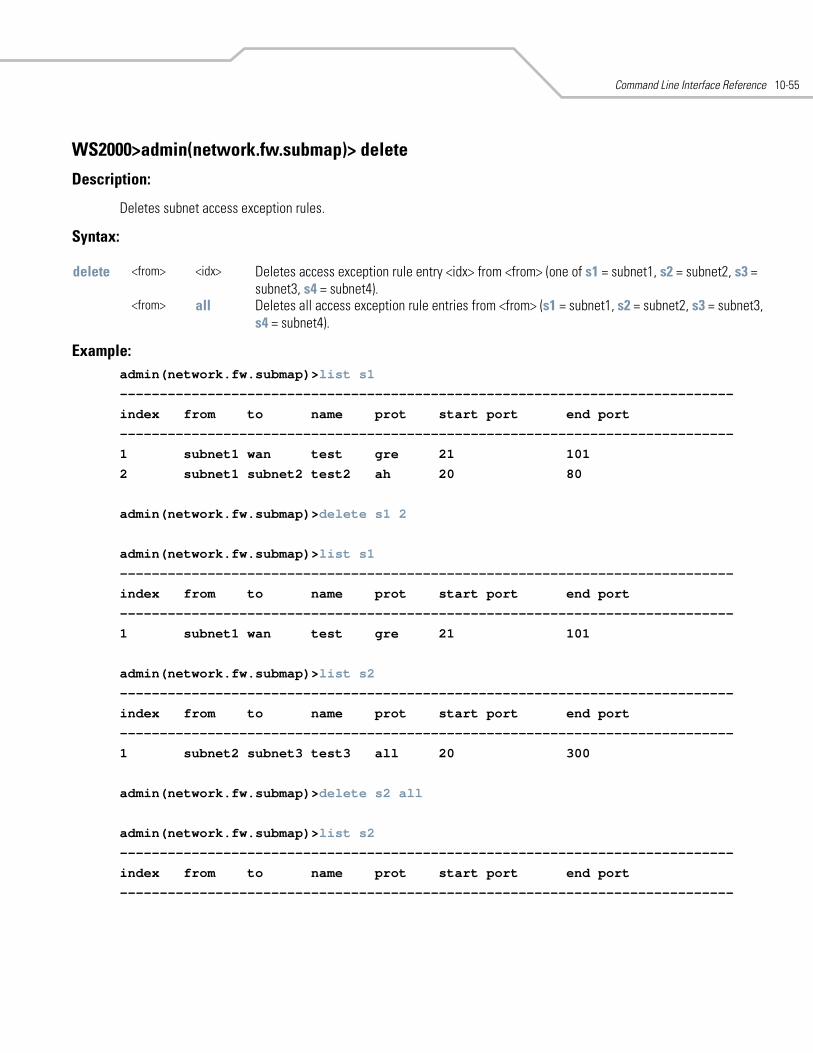
Command Line Interface Reference 10-55
WS2000>admin(network.fw.submap)> delete
Description:
Deletes subnet access exception rules.
Syntax:
Example: admin(network.fw.submap)>list s1
-----------------------------------------------------------------------------
index from to name prot start port end port
-----------------------------------------------------------------------------
1 subnet1 wan test gre 21 101
2 subnet1 subnet2 test2 ah 20 80
admin(network.fw.submap)>delete s1 2
admin(network.fw.submap)>list s1
-----------------------------------------------------------------------------
index from to name prot start port end port
-----------------------------------------------------------------------------
1 subnet1 wan test gre 21 101
admin(network.fw.submap)>list s2
-----------------------------------------------------------------------------
index from to name prot start port end port
-----------------------------------------------------------------------------
1 subnet2 subnet3 test3 all 20 300
admin(network.fw.submap)>delete s2 all
admin(network.fw.submap)>list s2
-----------------------------------------------------------------------------
index from to name prot start port end port
-----------------------------------------------------------------------------
delete <from> <idx> Deletes access exception rule entry <idx> from <from> (one of s1 = subnet1, s2 = subnet2, s3 = subnet3, s4 = subnet4).
<from> all Deletes all access exception rule entries from <from> (s1 = subnet1, s2 = subnet2, s3 = subnet3, s4 = subnet4).
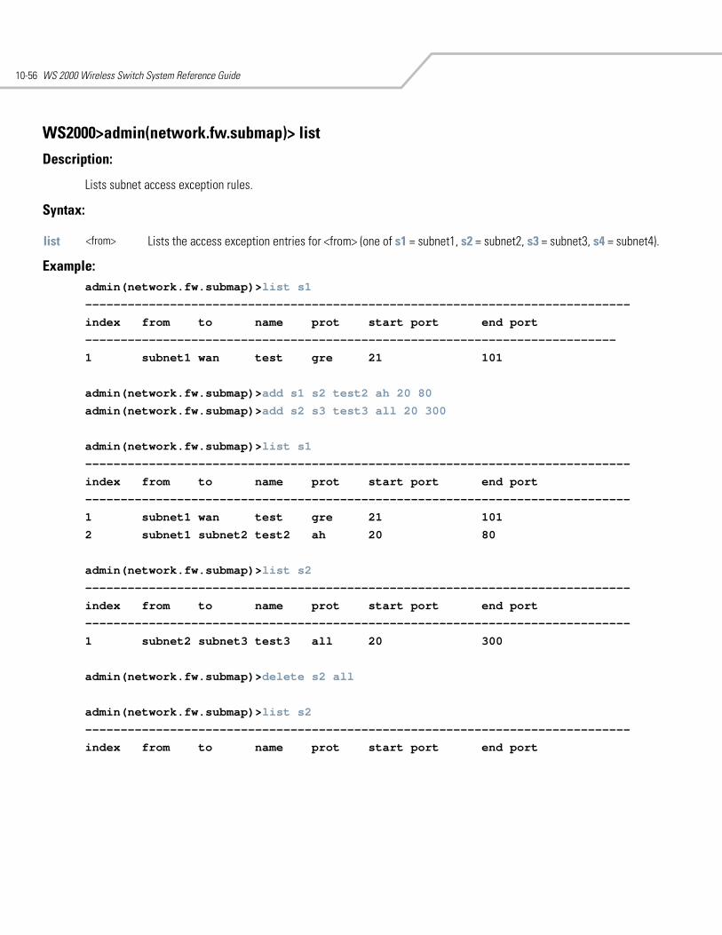
WS 2000 Wireless Switch System Reference Guide10-56
WS2000>admin(network.fw.submap)> list
Description:
Lists subnet access exception rules.
Syntax:
Example:admin(network.fw.submap)>list s1
-----------------------------------------------------------------------------
index from to name prot start port end port
---------------------------------------------------------------------------
1 subnet1 wan test gre 21 101
admin(network.fw.submap)>add s1 s2 test2 ah 20 80
admin(network.fw.submap)>add s2 s3 test3 all 20 300
admin(network.fw.submap)>list s1
-----------------------------------------------------------------------------
index from to name prot start port end port
-----------------------------------------------------------------------------
1 subnet1 wan test gre 21 101
2 subnet1 subnet2 test2 ah 20 80
admin(network.fw.submap)>list s2
-----------------------------------------------------------------------------
index from to name prot start port end port
-----------------------------------------------------------------------------
1 subnet2 subnet3 test3 all 20 300
admin(network.fw.submap)>delete s2 all
admin(network.fw.submap)>list s2
-----------------------------------------------------------------------------
index from to name prot start port end port
list <from> Lists the access exception entries for <from> (one of s1 = subnet1, s2 = subnet2, s3 = subnet3, s4 = subnet4).
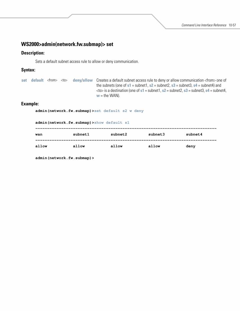
Command Line Interface Reference 10-57
WS2000>admin(network.fw.submap)> set
Description:
Sets a default subnet access rule to allow or deny communication.
Syntax:
Example:admin(network.fw.submap)>set default s2 w deny
admin(network.fw.submap)>show default s1
-----------------------------------------------------------------------------
wan subnet1 subnet2 subnet3 subnet4
-----------------------------------------------------------------------------
allow allow allow allow deny
admin(network.fw.submap)>
set default <from> <to> deny/allow Creates a default subnet access rule to deny or allow communication <from> one of the subnets (one of s1 = subnet1, s2 = subnet2, s3 = subnet3, s4 = subnet4) and <to> is a destination (one of s1 = subnet1, s2 = subnet2, s3 = subnet3, s4 = subnet4, w = the WAN).
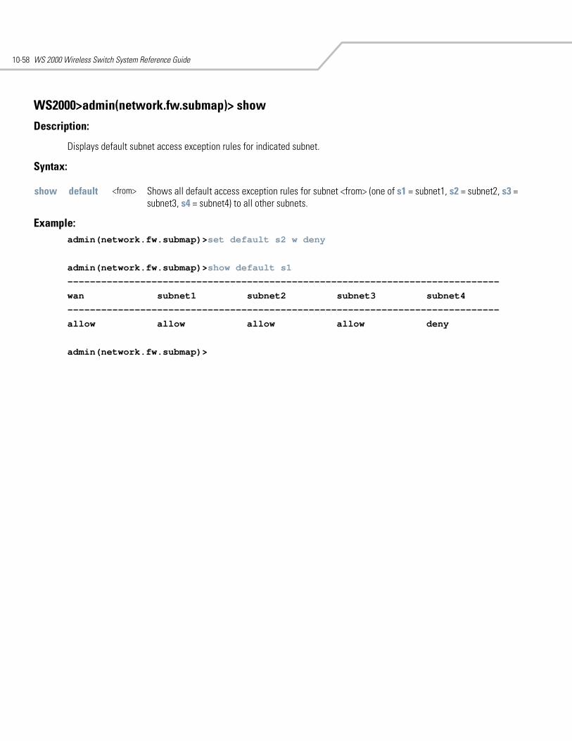
WS 2000 Wireless Switch System Reference Guide10-58
WS2000>admin(network.fw.submap)> show
Description:
Displays default subnet access exception rules for indicated subnet.
Syntax:
Example:admin(network.fw.submap)>set default s2 w deny
admin(network.fw.submap)>show default s1
-----------------------------------------------------------------------------
wan subnet1 subnet2 subnet3 subnet4
-----------------------------------------------------------------------------
allow allow allow allow deny
admin(network.fw.submap)>
show default <from> Shows all default access exception rules for subnet <from> (one of s1 = subnet1, s2 = subnet2, s3 = subnet3, s4 = subnet4) to all other subnets.
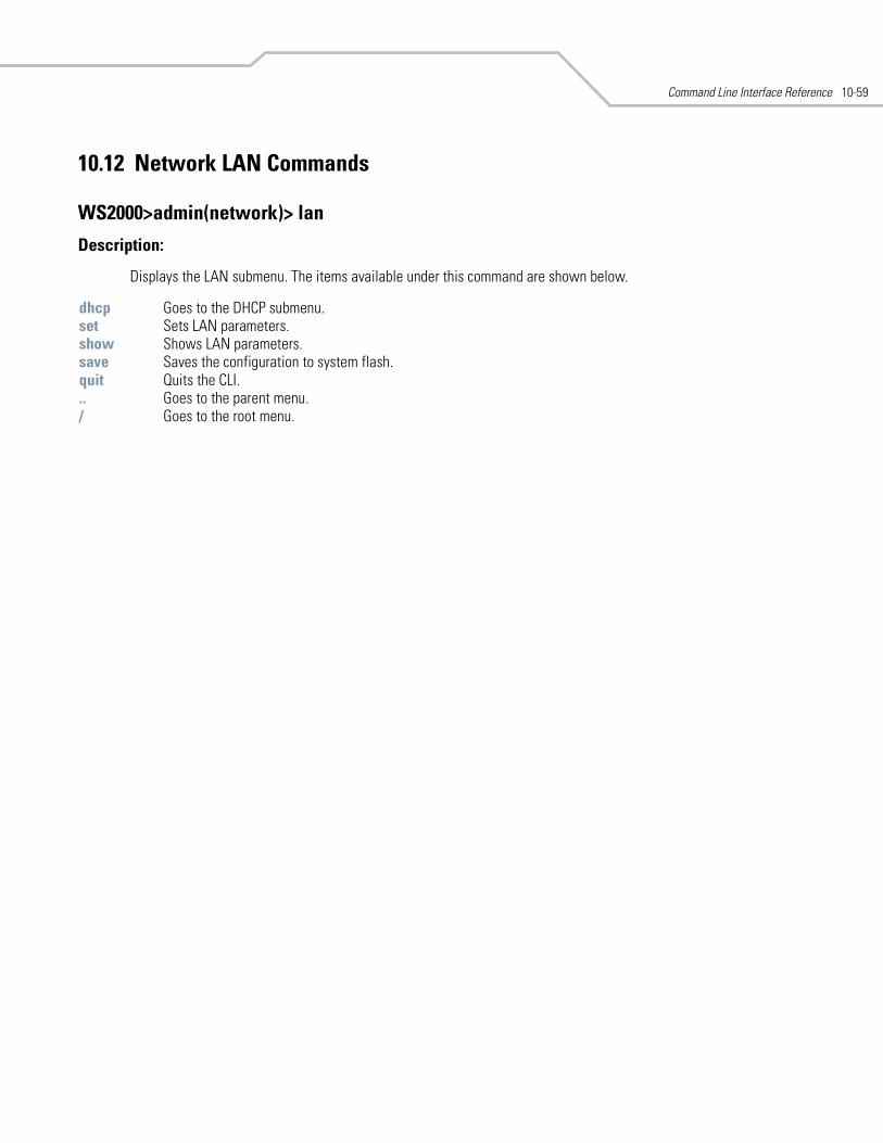
Command Line Interface Reference 10-59
10.12 Network LAN Commands
WS2000>admin(network)> lan
Description:
Displays the LAN submenu. The items available under this command are shown below.
dhcp Goes to the DHCP submenu. set Sets LAN parameters. show Shows LAN parameters. save Saves the configuration to system flash.quit Quits the CLI. .. Goes to the parent menu./ Goes to the root menu.
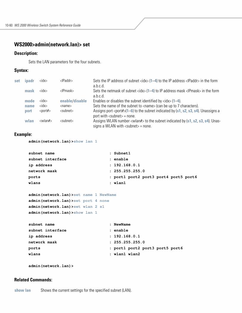
WS 2000 Wireless Switch System Reference Guide10-60
WS2000>admin(network.lan)> set
Description:
Sets the LAN parameters for the four subnets.
Syntax:
Example: admin(network.lan)>show lan 1
subnet name : Subnet1
subnet interface : enable
ip address : 192.168.0.1
network mask : 255.255.255.0
ports : port1 port2 port3 port4 port5 port6
wlans : wlan1
admin(network.lan)>set name 1 NewName
admin(network.lan)>set port 4 none
admin(network.lan)>set wlan 2 s1
admin(network.lan)>show lan 1
subnet name : NewName
subnet interface : enable
ip address : 192.168.0.1
network mask : 255.255.255.0
ports : port1 port2 port3 port5 port6
wlans : wlan1 wlan2
admin(network.lan)>
Related Commands:
set ipadr <idx> <IPaddr> Sets the IP address of subnet <idx> (1–4) to the IP address <IPaddr> in the form a.b.c.d.
mask <idx> <IPmask> Sets the netmask of subnet <idx> (1–4) to IP address mask <IPmask> in the form a.b.c.d.
mode <idx> enable/disable Enables or disables the subnet identified by <idx> (1–4).name <idx> <name> Sets the name of the subnet to <name> (can be up to 7 characters).port <port#> <subnet> Assigns port <port#>(1–6) to the subnet indicated by (s1, s2, s3, s4). Unassigns a
port with <subnet> = none.wlan <wlan#> <subnet> Assigns WLAN number <wlan#> to the subnet indicated by (s1, s2, s3, s4). Unas-
signs a WLAN with <subnet> = none.
show lan Shows the current settings for the specified subnet (LAN).

Command Line Interface Reference 10-61
WS2000>admin(network.lan)> show
Description:
Shows the LAN parameters.
Syntax:
Example:admin(network.lan)>show lan 1
subnet name : Subnet1
subnet interface : enable
ip address : 192.168.0.1
network mask : 255.255.255.0
ports : port1 port2 port3 port4 port5 port6
wlans : wlan1
admin(network.lan)>set name 1 NewName
admin(network.lan)>set port 4 none
admin(network.lan)>set wlan 2 s1
admin(network.lan)>show lan 1
subnet name : NewName
subnet interface : enable
ip address : 192.168.0.1
network mask : 255.255.255.0
ports : port1 port2 port3 port5 port6
wlans : wlan1 wlan2
admin(network.lan)>
show lan <idx> Shows the settings for the subnet <idx> (1–4).
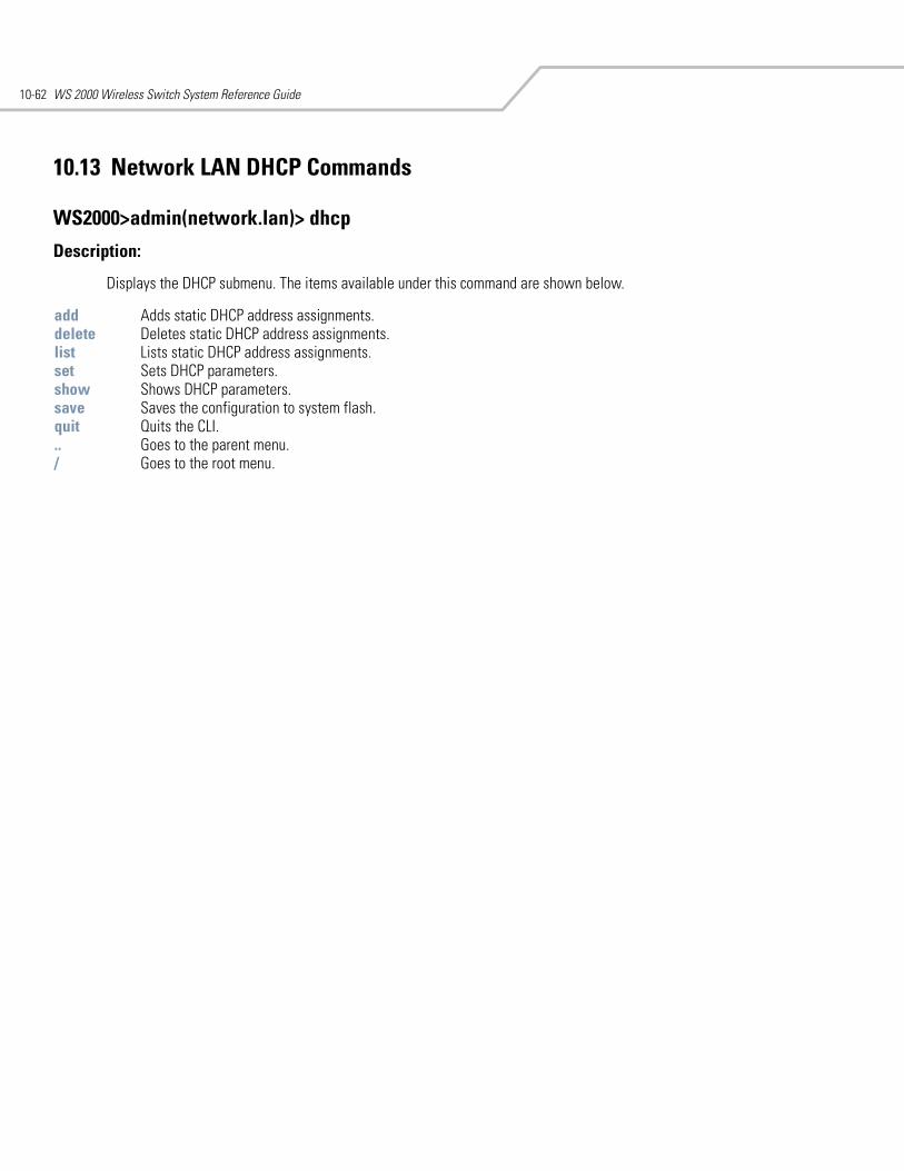
WS 2000 Wireless Switch System Reference Guide10-62
10.13 Network LAN DHCP Commands
WS2000>admin(network.lan)> dhcp
Description:
Displays the DHCP submenu. The items available under this command are shown below.
add Adds static DHCP address assignments. delete Deletes static DHCP address assignments. list Lists static DHCP address assignments. set Sets DHCP parameters. show Shows DHCP parameters. save Saves the configuration to system flash.quit Quits the CLI. .. Goes to the parent menu./ Goes to the root menu.
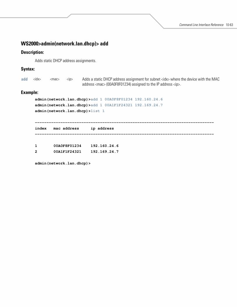
Command Line Interface Reference 10-63
WS2000>admin(network.lan.dhcp)> add
Description:
Adds static DHCP address assignments.
Syntax:
Example: admin(network.lan.dhcp)>add 1 00A0F8F01234 192.160.24.6
admin(network.lan.dhcp)>add 1 00A1F1F24321 192.169.24.7
admin(network.lan.dhcp)>list 1
-----------------------------------------------------------------------------
index mac address ip address
-----------------------------------------------------------------------------
1 00A0F8F01234 192.160.24.6
2 00A1F1F24321 192.169.24.7
admin(network.lan.dhcp)>
add <idx> <mac> <ip> Adds a static DHCP address assignment for subnet <idx> where the device with the MAC address <mac> (00A0F8F01234) assigned to the IP address <ip>.
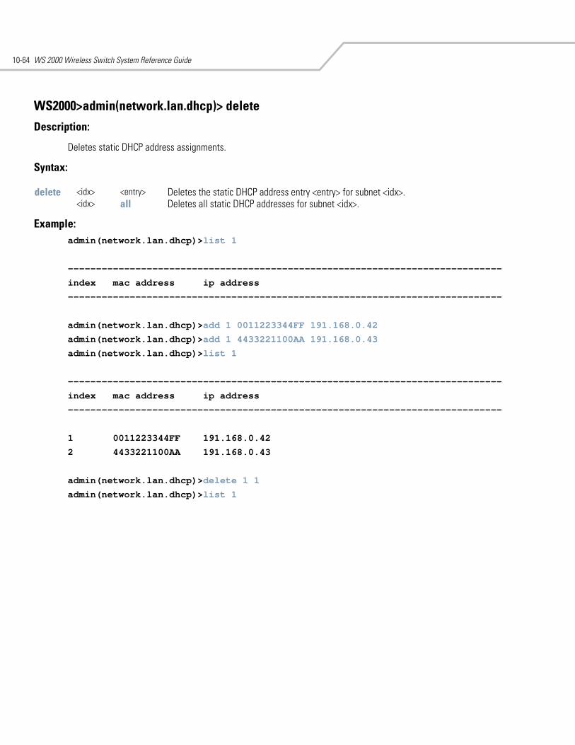
WS 2000 Wireless Switch System Reference Guide10-64
WS2000>admin(network.lan.dhcp)> delete
Description:
Deletes static DHCP address assignments.
Syntax:
Example: admin(network.lan.dhcp)>list 1
-----------------------------------------------------------------------------
index mac address ip address
-----------------------------------------------------------------------------
admin(network.lan.dhcp)>add 1 0011223344FF 191.168.0.42
admin(network.lan.dhcp)>add 1 4433221100AA 191.168.0.43
admin(network.lan.dhcp)>list 1
-----------------------------------------------------------------------------
index mac address ip address
-----------------------------------------------------------------------------
1 0011223344FF 191.168.0.42
2 4433221100AA 191.168.0.43
admin(network.lan.dhcp)>delete 1 1
admin(network.lan.dhcp)>list 1
delete <idx> <entry> Deletes the static DHCP address entry <entry> for subnet <idx>.<idx> all Deletes all static DHCP addresses for subnet <idx>.
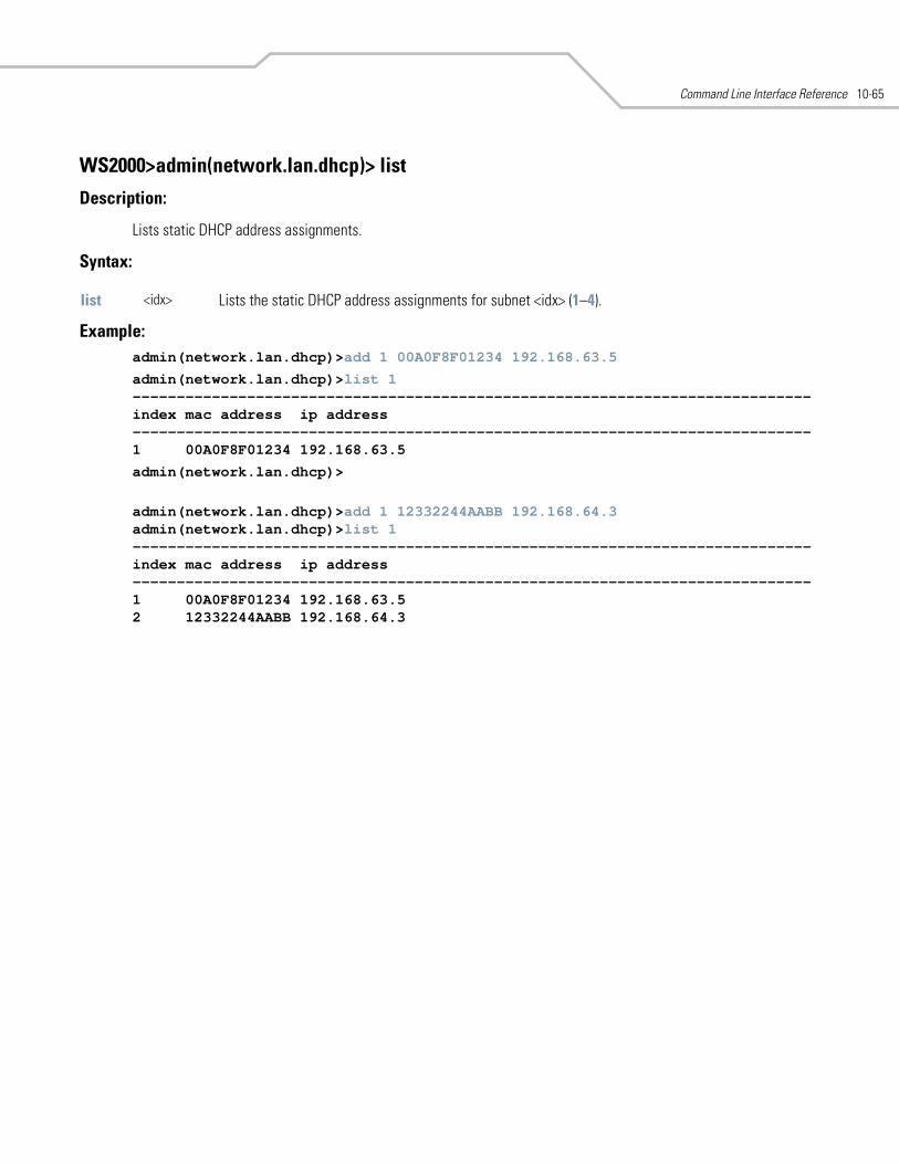
Command Line Interface Reference 10-65
WS2000>admin(network.lan.dhcp)> list
Description:
Lists static DHCP address assignments.
Syntax:
Example:admin(network.lan.dhcp)>add 1 00A0F8F01234 192.168.63.5
admin(network.lan.dhcp)>list 1-----------------------------------------------------------------------------index mac address ip address-----------------------------------------------------------------------------1 00A0F8F01234 192.168.63.5
admin(network.lan.dhcp)>
admin(network.lan.dhcp)>add 1 12332244AABB 192.168.64.3admin(network.lan.dhcp)>list 1-----------------------------------------------------------------------------index mac address ip address-----------------------------------------------------------------------------1 00A0F8F01234 192.168.63.52 12332244AABB 192.168.64.3
list <idx> Lists the static DHCP address assignments for subnet <idx> (1–4).
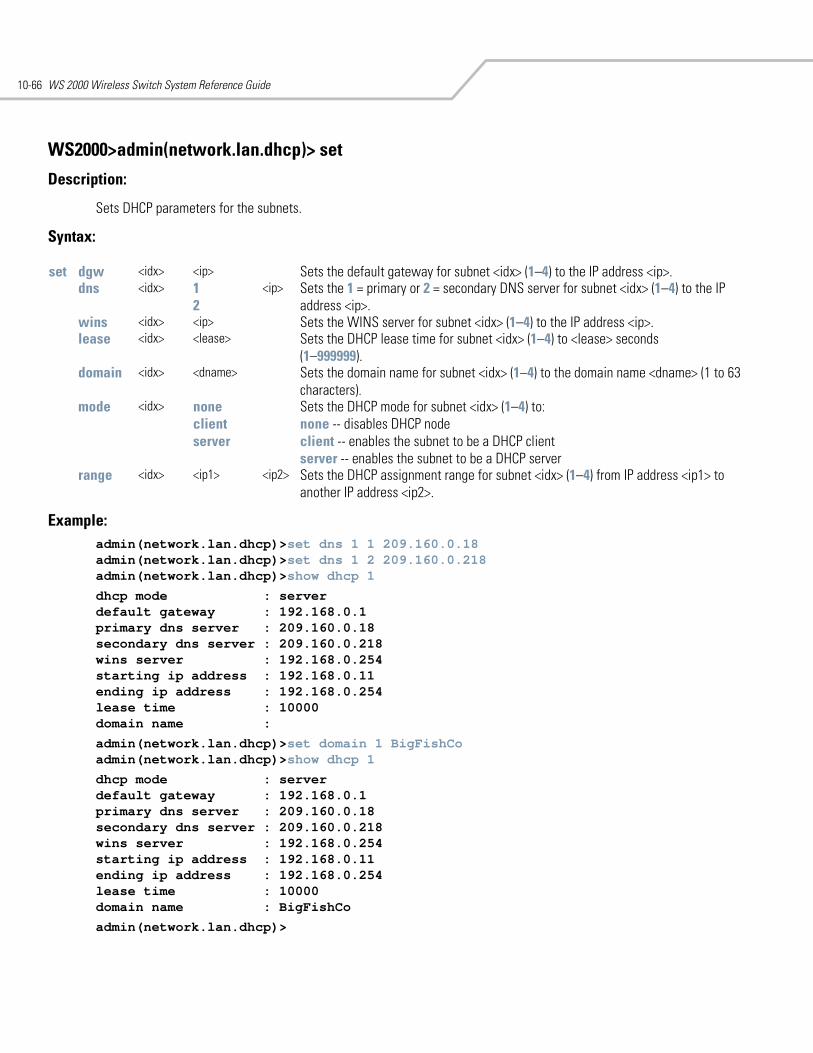
WS 2000 Wireless Switch System Reference Guide10-66
WS2000>admin(network.lan.dhcp)> set
Description:
Sets DHCP parameters for the subnets.
Syntax:
Example: admin(network.lan.dhcp)>set dns 1 1 209.160.0.18admin(network.lan.dhcp)>set dns 1 2 209.160.0.218admin(network.lan.dhcp)>show dhcp 1
dhcp mode : serverdefault gateway : 192.168.0.1primary dns server : 209.160.0.18secondary dns server : 209.160.0.218wins server : 192.168.0.254starting ip address : 192.168.0.11ending ip address : 192.168.0.254lease time : 10000domain name :
admin(network.lan.dhcp)>set domain 1 BigFishCoadmin(network.lan.dhcp)>show dhcp 1
dhcp mode : serverdefault gateway : 192.168.0.1primary dns server : 209.160.0.18secondary dns server : 209.160.0.218wins server : 192.168.0.254starting ip address : 192.168.0.11ending ip address : 192.168.0.254lease time : 10000domain name : BigFishCo
admin(network.lan.dhcp)>
set dgw <idx> <ip> Sets the default gateway for subnet <idx> (1–4) to the IP address <ip>. dns <idx> 1
2 <ip> Sets the 1 = primary or 2 = secondary DNS server for subnet <idx> (1–4) to the IP
address <ip>.wins <idx> <ip> Sets the WINS server for subnet <idx> (1–4) to the IP address <ip>.lease <idx> <lease> Sets the DHCP lease time for subnet <idx> (1–4) to <lease> seconds
(1–999999).domain <idx> <dname> Sets the domain name for subnet <idx> (1–4) to the domain name <dname> (1 to 63
characters).mode <idx> none
clientserver
Sets the DHCP mode for subnet <idx> (1–4) to:none -- disables DHCP node client -- enables the subnet to be a DHCP clientserver -- enables the subnet to be a DHCP server
range <idx> <ip1> <ip2> Sets the DHCP assignment range for subnet <idx> (1–4) from IP address <ip1> to another IP address <ip2>.
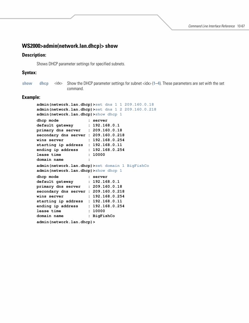
Command Line Interface Reference 10-67
WS2000>admin(network.lan.dhcp)> show
Description:
Shows DHCP parameter settings for specified subnets.
Syntax:
Example:admin(network.lan.dhcp)>set dns 1 1 209.160.0.18admin(network.lan.dhcp)>set dns 1 2 209.160.0.218admin(network.lan.dhcp)>show dhcp 1
dhcp mode : serverdefault gateway : 192.168.0.1primary dns server : 209.160.0.18secondary dns server : 209.160.0.218wins server : 192.168.0.254starting ip address : 192.168.0.11ending ip address : 192.168.0.254lease time : 10000domain name :
admin(network.lan.dhcp)>set domain 1 BigFishCoadmin(network.lan.dhcp)>show dhcp 1
dhcp mode : serverdefault gateway : 192.168.0.1primary dns server : 209.160.0.18secondary dns server : 209.160.0.218wins server : 192.168.0.254starting ip address : 192.168.0.11ending ip address : 192.168.0.254lease time : 10000domain name : BigFishCo
admin(network.lan.dhcp)>
show dhcp <idx> Show the DHCP parameter settings for subnet <idx> (1–4). These parameters are set with the set command.
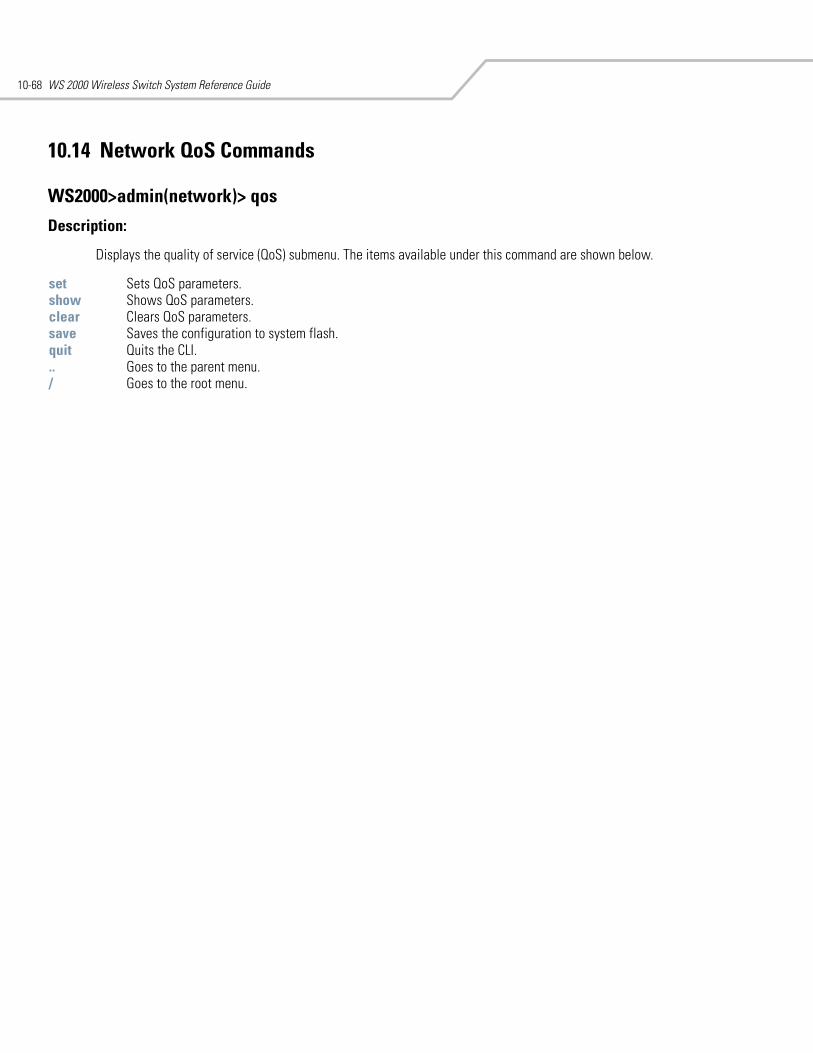
WS 2000 Wireless Switch System Reference Guide10-68
10.14 Network QoS Commands
WS2000>admin(network)> qos
Description:
Displays the quality of service (QoS) submenu. The items available under this command are shown below.
set Sets QoS parameters. show Shows QoS parameters. clear Clears QoS parameters. save Saves the configuration to system flash.quit Quits the CLI. .. Goes to the parent menu./ Goes to the root menu.
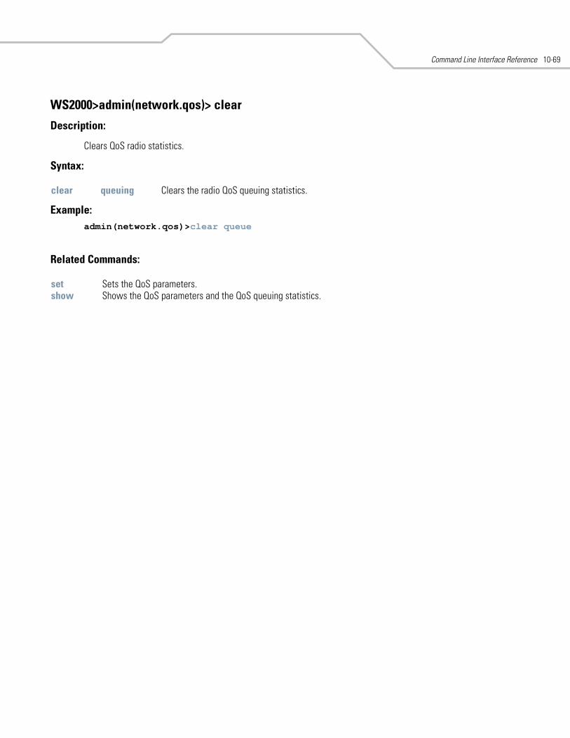
Command Line Interface Reference 10-69
WS2000>admin(network.qos)> clear
Description:
Clears QoS radio statistics.
Syntax:
Example: admin(network.qos)>clear queue
Related Commands:
clear queuing Clears the radio QoS queuing statistics.
set Sets the QoS parameters.show Shows the QoS parameters and the QoS queuing statistics.
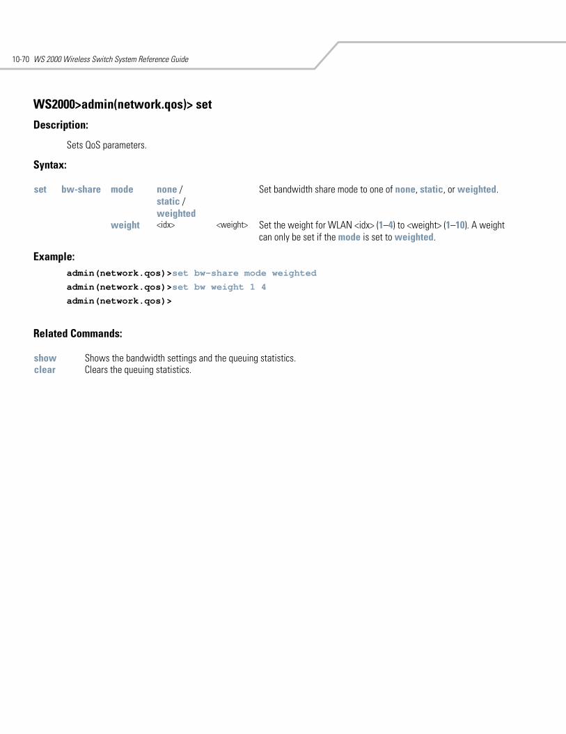
WS 2000 Wireless Switch System Reference Guide10-70
WS2000>admin(network.qos)> set
Description:
Sets QoS parameters.
Syntax:
Example: admin(network.qos)>set bw-share mode weighted
admin(network.qos)>set bw weight 1 4
admin(network.qos)>
Related Commands:
set bw-share mode none /static /weighted
Set bandwidth share mode to one of none, static, or weighted.
weight <idx> <weight> Set the weight for WLAN <idx> (1–4) to <weight> (1–10). A weight can only be set if the mode is set to weighted.
show Shows the bandwidth settings and the queuing statistics.clear Clears the queuing statistics.
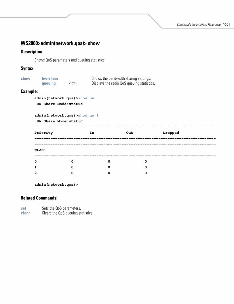
Command Line Interface Reference 10-71
WS2000>admin(network.qos)> show
Description:
Shows QoS parameters and queuing statistics.
Syntax:
Example: admin(network.qos)>show bw
BW Share Mode:static
admin(network.qos)>show qu 1
BW Share Mode:static
-------------------------------------------------------------------------------
Priority In Out Dropped
-------------------------------------------------------------------------------
-------------------------------------------------------------------------------
WLAN: 1
-------------------------------------------------------------------------------
0 0 0 0
1 0 0 0
2 0 0 0
admin(network.qos)>
Related Commands:
show bw-share Shows the bandwidth sharing settings.queuing <idx> Displays the radio QoS queuing statistics.
set Sets the QoS parameters.clear Clears the QoS queuing statistics.
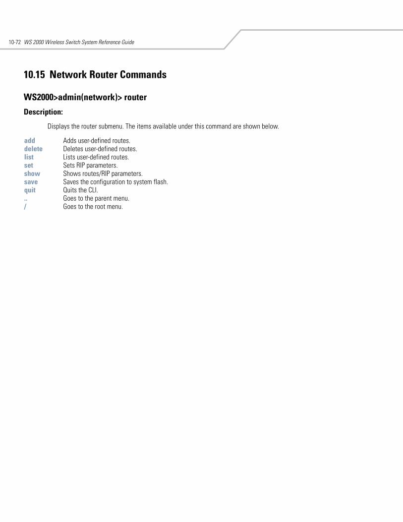
WS 2000 Wireless Switch System Reference Guide10-72
10.15 Network Router Commands
WS2000>admin(network)> router
Description:
Displays the router submenu. The items available under this command are shown below.
add Adds user-defined routes. delete Deletes user-defined routes.list Lists user-defined routes.set Sets RIP parameters. show Shows routes/RIP parameters. save Saves the configuration to system flash.quit Quits the CLI. .. Goes to the parent menu./ Goes to the root menu.
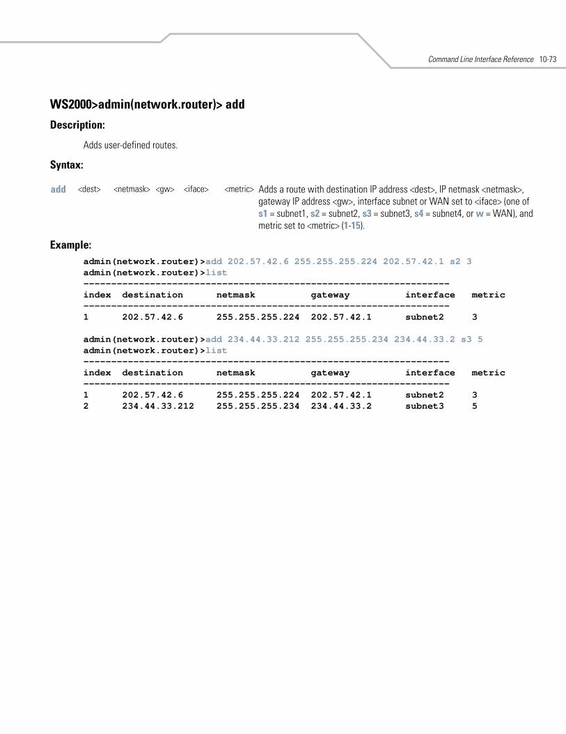
Command Line Interface Reference 10-73
WS2000>admin(network.router)> add
Description:
Adds user-defined routes.
Syntax:
Example: admin(network.router)>add 202.57.42.6 255.255.255.224 202.57.42.1 s2 3admin(network.router)>list------------------------------------------------------------------index destination netmask gateway interface metric------------------------------------------------------------------1 202.57.42.6 255.255.255.224 202.57.42.1 subnet2 3
admin(network.router)>add 234.44.33.212 255.255.255.234 234.44.33.2 s3 5admin(network.router)>list------------------------------------------------------------------index destination netmask gateway interface metric------------------------------------------------------------------1 202.57.42.6 255.255.255.224 202.57.42.1 subnet2 32 234.44.33.212 255.255.255.234 234.44.33.2 subnet3 5
add <dest> <netmask> <gw> <iface> <metric> Adds a route with destination IP address <dest>, IP netmask <netmask>, gateway IP address <gw>, interface subnet or WAN set to <iface> (one of s1 = subnet1, s2 = subnet2, s3 = subnet3, s4 = subnet4, or w = WAN), and metric set to <metric> (1-15).
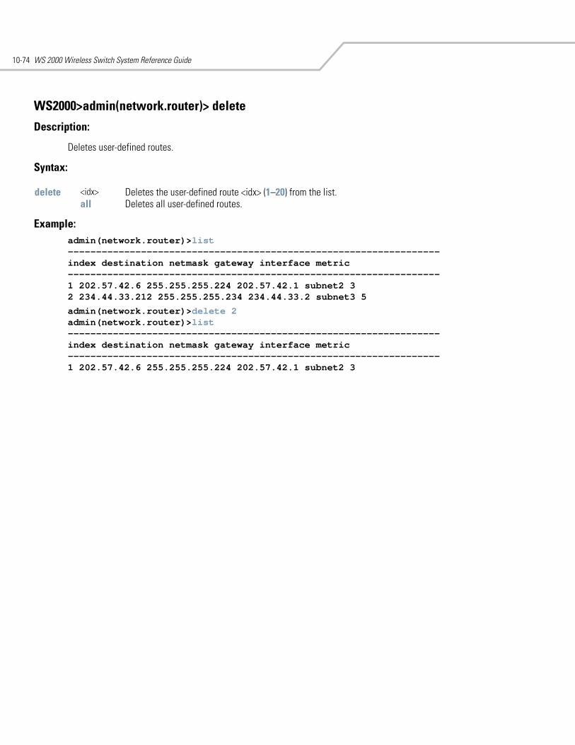
WS 2000 Wireless Switch System Reference Guide10-74
WS2000>admin(network.router)> delete
Description:
Deletes user-defined routes.
Syntax:
Example: admin(network.router)>list------------------------------------------------------------------index destination netmask gateway interface metric------------------------------------------------------------------1 202.57.42.6 255.255.255.224 202.57.42.1 subnet2 32 234.44.33.212 255.255.255.234 234.44.33.2 subnet3 5
admin(network.router)>delete 2admin(network.router)>list------------------------------------------------------------------index destination netmask gateway interface metric------------------------------------------------------------------1 202.57.42.6 255.255.255.224 202.57.42.1 subnet2 3
delete <idx> Deletes the user-defined route <idx> (1–20) from the list.all Deletes all user-defined routes.
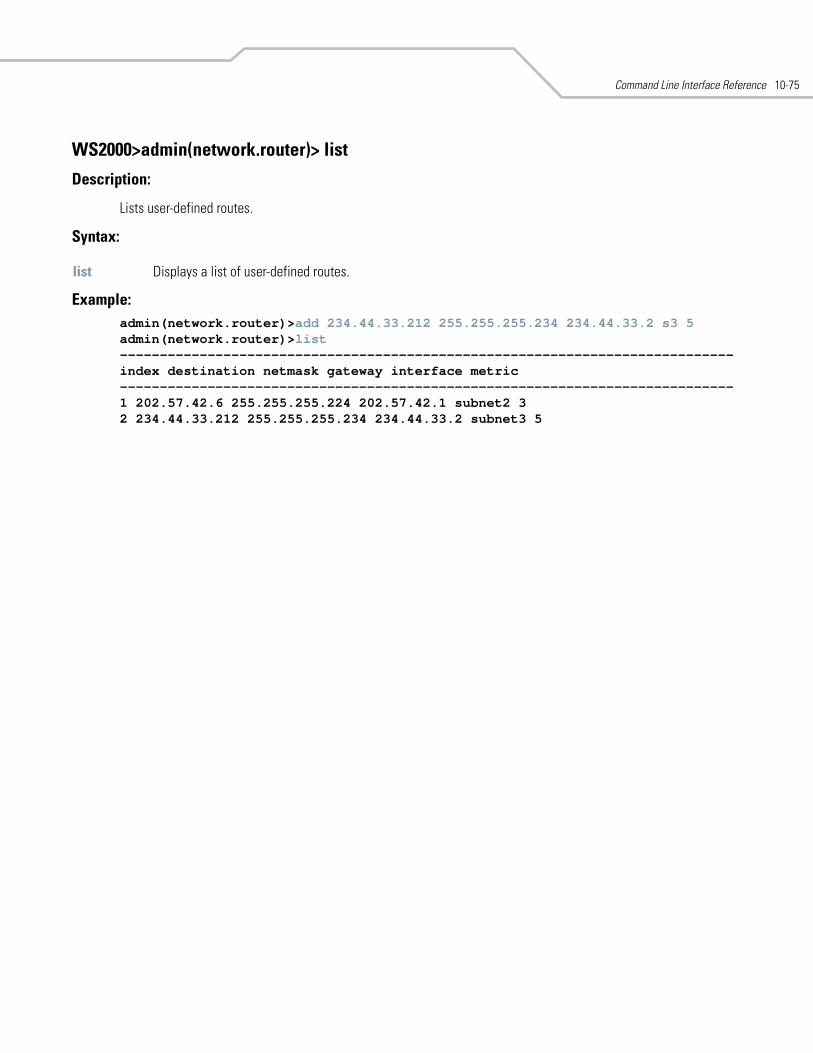
Command Line Interface Reference 10-75
WS2000>admin(network.router)> list
Description:
Lists user-defined routes.
Syntax:
Example: admin(network.router)>add 234.44.33.212 255.255.255.234 234.44.33.2 s3 5admin(network.router)>list-----------------------------------------------------------------------------index destination netmask gateway interface metric-----------------------------------------------------------------------------1 202.57.42.6 255.255.255.224 202.57.42.1 subnet2 32 234.44.33.212 255.255.255.234 234.44.33.2 subnet3 5
list Displays a list of user-defined routes.
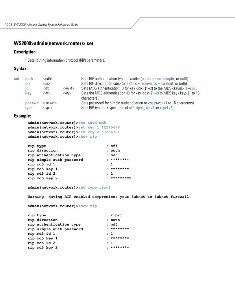
WS 2000 Wireless Switch System Reference Guide10-76
WS2000>admin(network.router)> set
Description:
Sets routing information protocol (RIP) parameters.
Syntax:
Example: admin(network.router)>set auth md5admin(network.router)>set key 1 12345678admin(network.router)>set key 2 87654321admin(network.router)>show rip
rip type : offrip direction : bothrip authentication type : md5rip simple auth password : ********rip md5 id 1 : 1rip md5 key 1 : ********rip md5 id 2 : 1rip md5 key 2 : ********S
admin(network.router)>set type ripv1
Warning: Having RIP enabled compromises your Subnet to Subnet firewall.
admin(network.router)>show rip
rip type : ripv1rip direction : bothrip authentication type : md5rip simple auth password : ********rip md5 id 1 : 1rip md5 key 1 : ********rip md5 id 2 : 1rip md5 key 2 : ********
set auth <auth> Sets RIP authentication type to <auth> (one of none, simple, or md5).dir <dir> Sets RIP direction to <dir> (one of rx = receive, tx = transmit, or both). id <idx> <keyid> Sets MD5 authentication ID for key <idx> (1–2) to the MD5 <keyid> (1–256).key <idx> <key> Sets the MD5 authentication ID for key <idx> (1–2) to MD5 key <key> (1 to 16
characters).passwd <passwd> Sets password for simple authentication to <passwd> (1 to 16 characters). type <type> Sets RIP type to <type> (one of off, ripv1, ripv2, or ripv1v2).
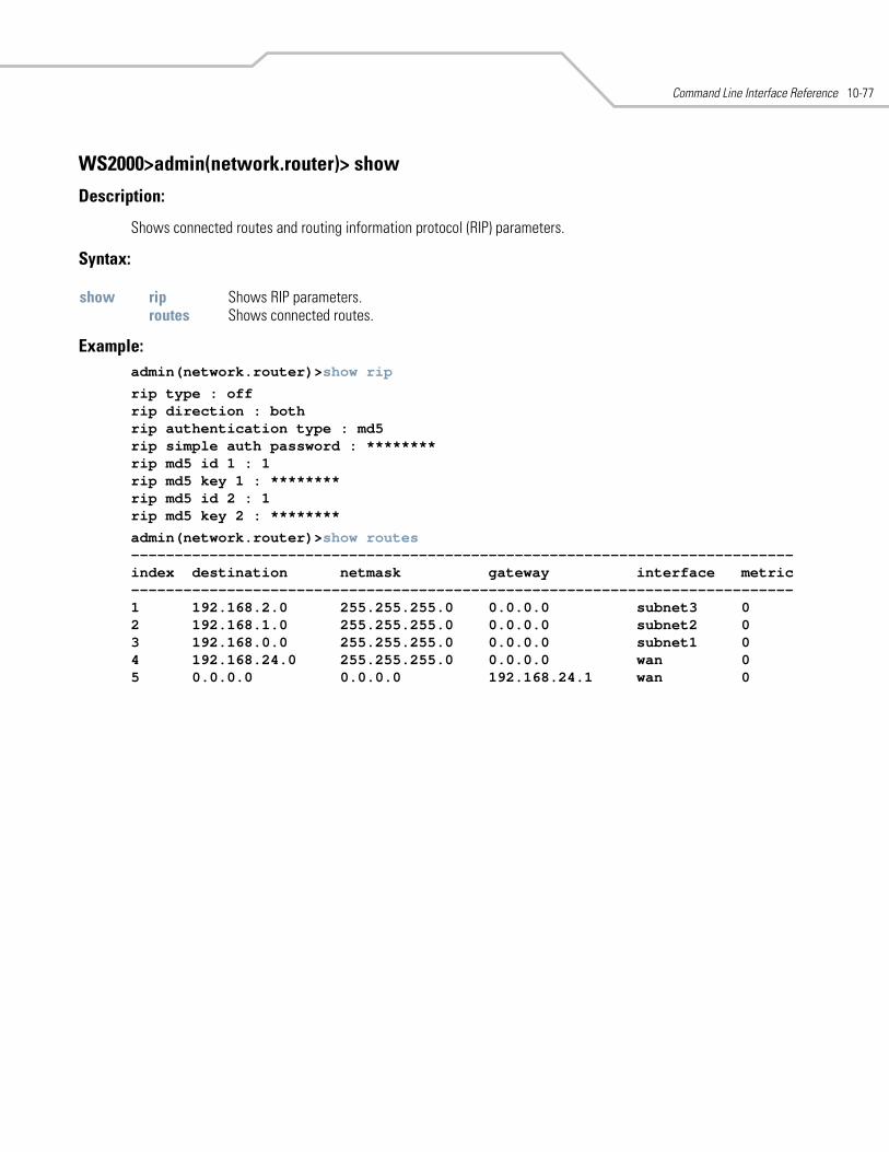
Command Line Interface Reference 10-77
WS2000>admin(network.router)> show
Description:
Shows connected routes and routing information protocol (RIP) parameters.
Syntax:
Example: admin(network.router)>show rip
rip type : offrip direction : bothrip authentication type : md5rip simple auth password : ********rip md5 id 1 : 1rip md5 key 1 : ********rip md5 id 2 : 1rip md5 key 2 : ********
admin(network.router)>show routes----------------------------------------------------------------------------index destination netmask gateway interface metric----------------------------------------------------------------------------1 192.168.2.0 255.255.255.0 0.0.0.0 subnet3 02 192.168.1.0 255.255.255.0 0.0.0.0 subnet2 03 192.168.0.0 255.255.255.0 0.0.0.0 subnet1 04 192.168.24.0 255.255.255.0 0.0.0.0 wan 05 0.0.0.0 0.0.0.0 192.168.24.1 wan 0
show rip Shows RIP parameters.routes Shows connected routes.
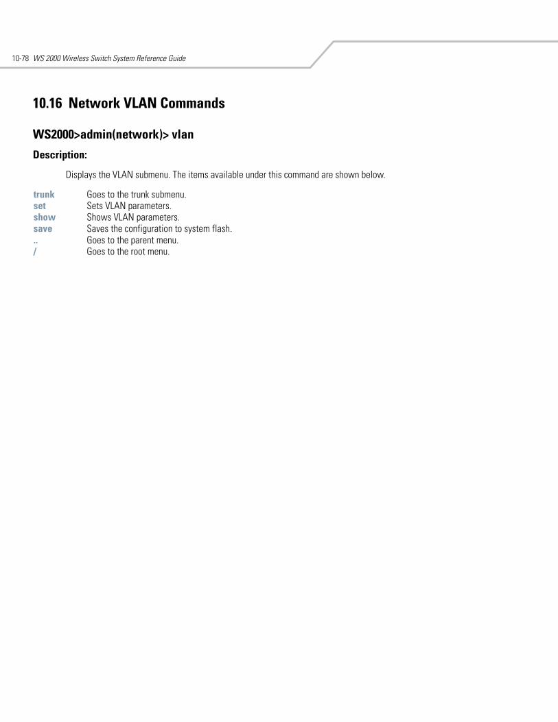
WS 2000 Wireless Switch System Reference Guide10-78
10.16 Network VLAN Commands
WS2000>admin(network)> vlan
Description:
Displays the VLAN submenu. The items available under this command are shown below.
trunk Goes to the trunk submenu. set Sets VLAN parameters. show Shows VLAN parameters. save Saves the configuration to system flash... Goes to the parent menu./ Goes to the root menu.
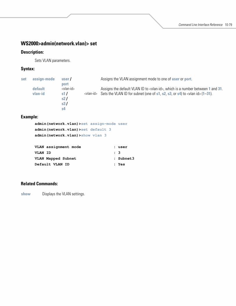
Command Line Interface Reference 10-79
WS2000>admin(network.vlan)> set
Description:
Sets VLAN parameters.
Syntax:
Example: admin(network.vlan)>set assign-mode user
admin(network.vlan)>set default 3
admin(network.vlan)>show vlan 3
VLAN assignment mode : user
VLAN ID : 3
VLAN Mapped Subnet : Subnet3
Default VLAN ID : Yes
Related Commands:
set assign-mode user /port
Assigns the VLAN assignment mode to one of user or port.
default <vlan-id> Assigns the default VLAN ID to <vlan-id>, which is a number between 1 and 31.vlan-id s1 /
s2 / s3 / s4
<vlan-id> Sets the VLAN ID for subnet (one of s1, s2, s3, or s4) to <vlan id> (1–31).
show Displays the VLAN settings.
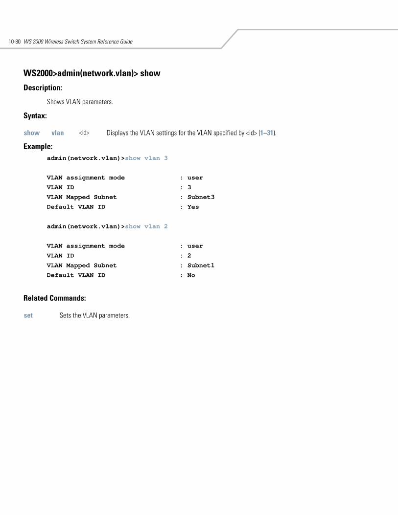
WS 2000 Wireless Switch System Reference Guide10-80
WS2000>admin(network.vlan)> show
Description:
Shows VLAN parameters.
Syntax:
Example: admin(network.vlan)>show vlan 3
VLAN assignment mode : user
VLAN ID : 3
VLAN Mapped Subnet : Subnet3
Default VLAN ID : Yes
admin(network.vlan)>show vlan 2
VLAN assignment mode : user
VLAN ID : 2
VLAN Mapped Subnet : Subnet1
Default VLAN ID : No
Related Commands:
show vlan <id> Displays the VLAN settings for the VLAN specified by <id> (1–31).
set Sets the VLAN parameters.
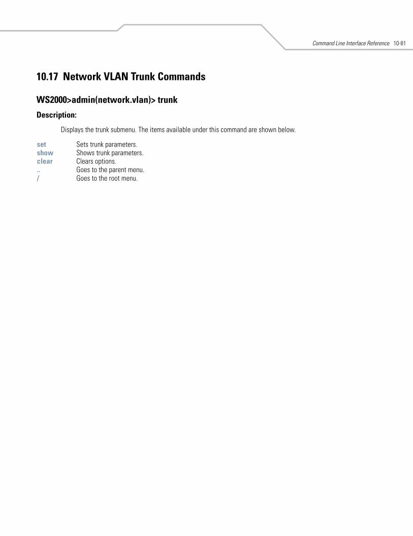
Command Line Interface Reference 10-81
10.17 Network VLAN Trunk Commands
WS2000>admin(network.vlan)> trunk
Description:
Displays the trunk submenu. The items available under this command are shown below.
set Sets trunk parameters. show Shows trunk parameters. clear Clears options... Goes to the parent menu./ Goes to the root menu.
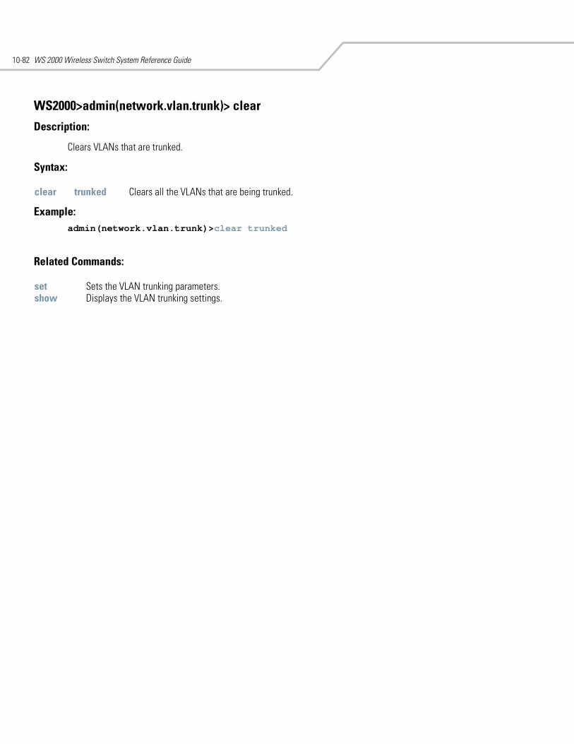
WS 2000 Wireless Switch System Reference Guide10-82
WS2000>admin(network.vlan.trunk)> clear
Description:
Clears VLANs that are trunked.
Syntax:
Example: admin(network.vlan.trunk)>clear trunked
Related Commands:
clear trunked Clears all the VLANs that are being trunked.
set Sets the VLAN trunking parameters.show Displays the VLAN trunking settings.
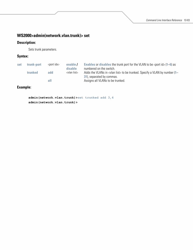
Command Line Interface Reference 10-83
WS2000>admin(network.vlan.trunk)> set
Description:
Sets trunk parameters.
Syntax:
Example:
admin(network.vlan.trunk)>set trunked add 3,4
admin(network.vlan.trunk)>
set trunk-port <port idx> enable / disable
Enables or disables the trunk port for the VLAN to be <port id> (1–6) as numbered on the switch.
trunked add <vlan list> Adds the VLANs in <vlan list> to be trunked. Specify a VLAN by number (1–31), separated by commas.
all Assigns all VLANs to be trunked.
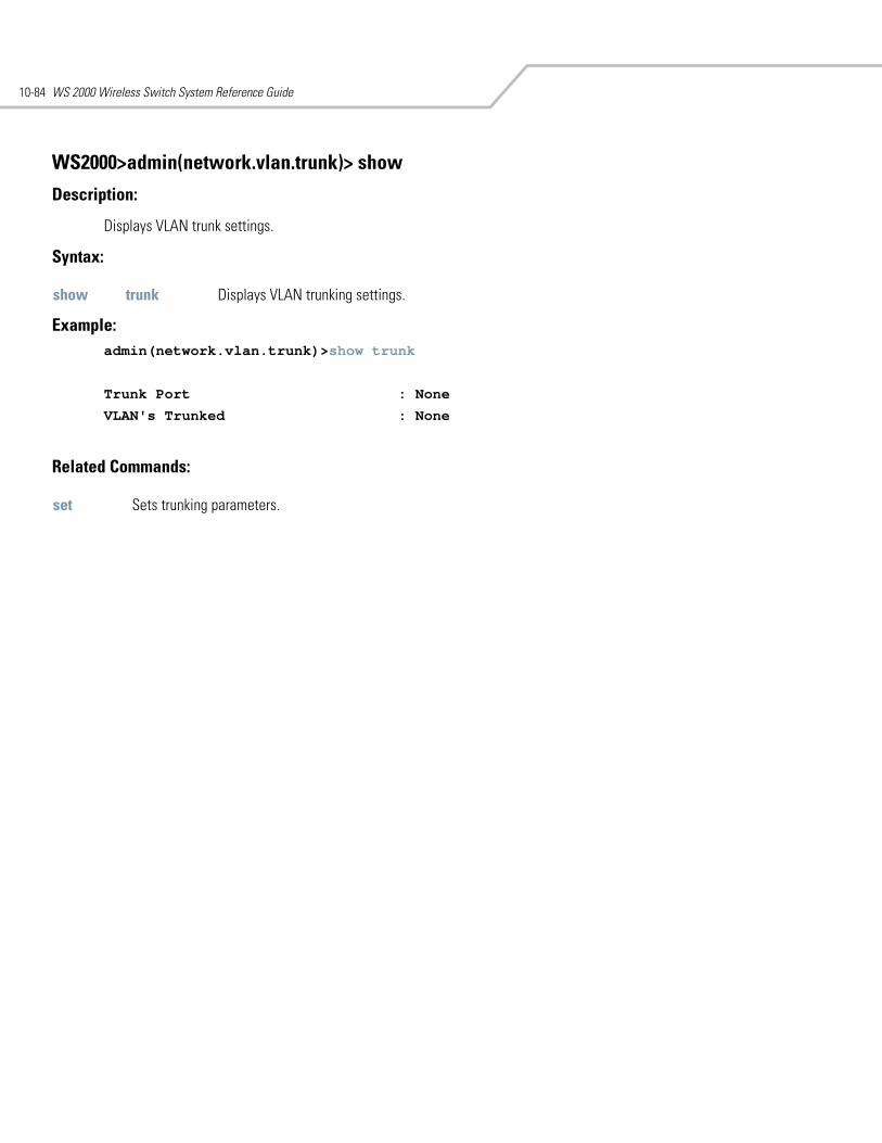
WS 2000 Wireless Switch System Reference Guide10-84
WS2000>admin(network.vlan.trunk)> show
Description:
Displays VLAN trunk settings.
Syntax:
Example: admin(network.vlan.trunk)>show trunk
Trunk Port : None
VLAN's Trunked : None
Related Commands:
show trunk Displays VLAN trunking settings.
set Sets trunking parameters.
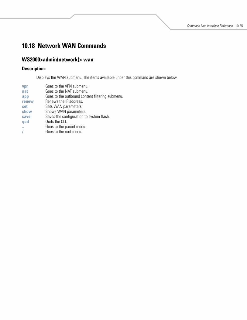
Command Line Interface Reference 10-85
10.18 Network WAN Commands
WS2000>admin(network)> wan
Description:
Displays the WAN submenu. The items available under this command are shown below.
vpn Goes to the VPN submenu. nat Goes to the NAT submenu. app Goes to the outbound content filtering submenu. renew Renews the IP address. set Sets WAN parameters. show Shows WAN parameters. save Saves the configuration to system flash.quit Quits the CLI. .. Goes to the parent menu./ Goes to the root menu.
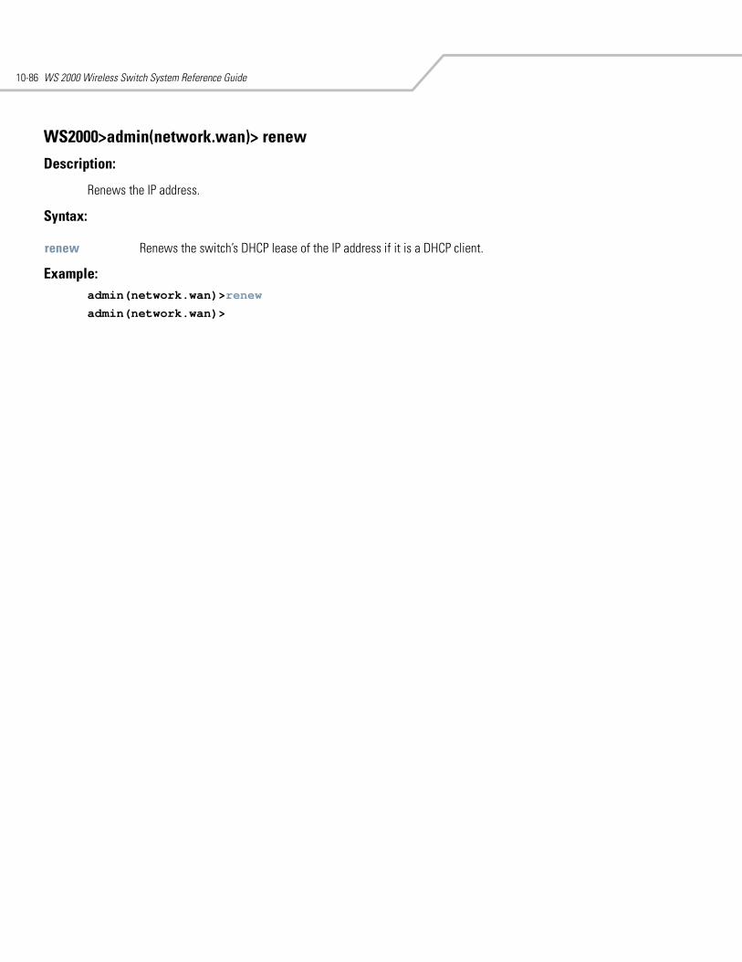
WS 2000 Wireless Switch System Reference Guide10-86
WS2000>admin(network.wan)> renew
Description:
Renews the IP address.
Syntax:
Example: admin(network.wan)>renew
admin(network.wan)>
renew Renews the switch’s DHCP lease of the IP address if it is a DHCP client.
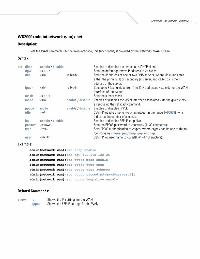
Command Line Interface Reference 10-87
WS2000>admin(network.wan)> set
Description:
Sets the WAN parameters. In the Web interface, this functionality if provided by the Network->WAN screen.
Syntax:
Example: admin(network.wan)>set dhcp enable
admin(network.wan)>set dgw 192.168.122.25
admin(network.wan)>set pppoe mode enable
admin(network.wan)>set pppoe type chap
admin(network.wan)>set pppoe user JohnDoe
admin(network.wan)>set pppoe passwd @#$goodpassword%$#
admin(network.wan)>set pppoe keepalive enable
Related Commands:
set dhcp enable / disable Enables or disables the switch as a DHCP client.dgw <a.b.c.d> Sets the default gateway IP address to <a.b.c.d>.dns <idx> <a.b.c.d> Sets the IP address of one or two DNS servers, where <idx> indicates
either the primary (1) or secondary (2) server, and <a.b.c.d> is the IP address of the server.
ipadr <idx> <a.b.c.d> Sets up to 8 (using <idx> from 1 to 8) IP addresses <a.b.c.d> for the WAN interface of the switch.
mask <a.b.c.d> Sets the subnet mask. mode <idx> enable / disable Enables or disables the WAN interface associated with the given <idx>
as set using the set ipadr command.pppoe mode enable / disable Enables or disables PPPoE.idle <val> Sets PPPoE idle time to <val> (an integer in the range 1–65535), which
indicates the number of seconds.ka enable / disable Enables or disables PPPoE keepalive.passwd <passwd> Sets the PPPoE password to <passwd> (1–39 characters).type <type> Sets PPPoE authentication to <type>, where <type> can be one of the fol-
lowing values: none, pap/chap, pap, or chap.user <userID> Sets PPPoE user name to <userID> (1–47 characters).
show ip Shows the IP settings for the WAN. pppoe Shows the PPPoE settings for the WAN.
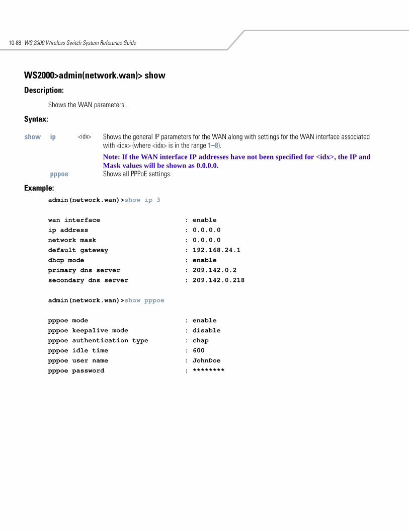
WS 2000 Wireless Switch System Reference Guide10-88
WS2000>admin(network.wan)> show
Description:
Shows the WAN parameters.
Syntax:
Example: admin(network.wan)>show ip 3
wan interface : enable
ip address : 0.0.0.0
network mask : 0.0.0.0
default gateway : 192.168.24.1
dhcp mode : enable
primary dns server : 209.142.0.2
secondary dns server : 209.142.0.218
admin(network.wan)>show pppoe
pppoe mode : enable
pppoe keepalive mode : disable
pppoe authentication type : chap
pppoe idle time : 600
pppoe user name : JohnDoe
pppoe password : ********
show ip <idx> Shows the general IP parameters for the WAN along with settings for the WAN interface associated with <idx> (where <idx> is in the range 1–8).
Note: If the WAN interface IP addresses have not been specified for <idx>, the IP and Mask values will be shown as 0.0.0.0.
pppoe Shows all PPPoE settings.
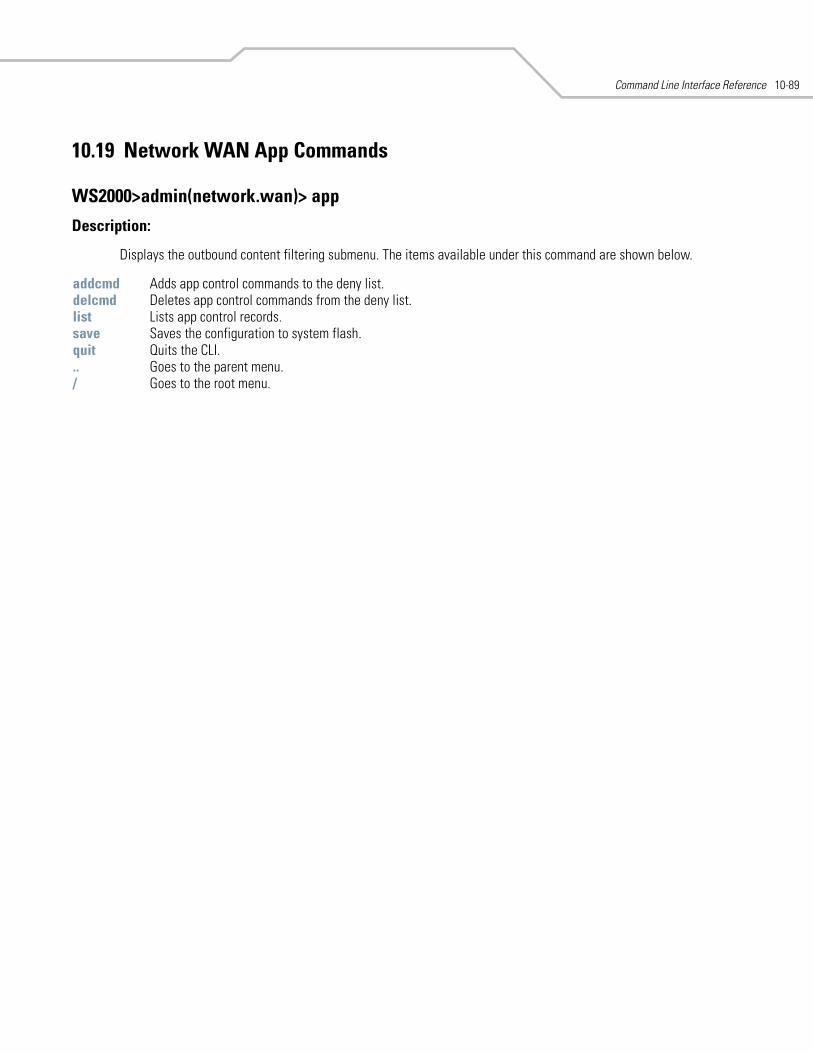
Command Line Interface Reference 10-89
10.19 Network WAN App Commands
WS2000>admin(network.wan)> app
Description:
Displays the outbound content filtering submenu. The items available under this command are shown below.
addcmd Adds app control commands to the deny list.delcmd Deletes app control commands from the deny list.list Lists app control records.save Saves the configuration to system flash.quit Quits the CLI. .. Goes to the parent menu./ Goes to the root menu.
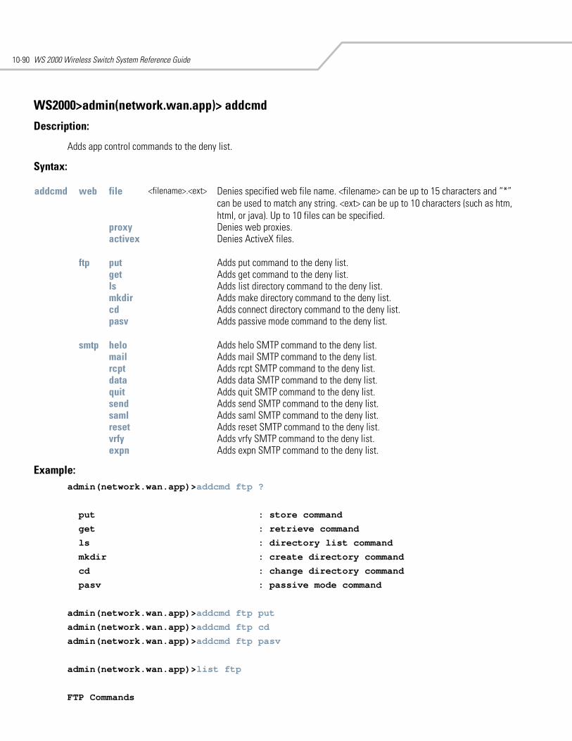
WS 2000 Wireless Switch System Reference Guide10-90
WS2000>admin(network.wan.app)> addcmd
Description:
Adds app control commands to the deny list.
Syntax:
Example: admin(network.wan.app)>addcmd ftp ?
put : store command
get : retrieve command
ls : directory list command
mkdir : create directory command
cd : change directory command
pasv : passive mode command
admin(network.wan.app)>addcmd ftp put
admin(network.wan.app)>addcmd ftp cd
admin(network.wan.app)>addcmd ftp pasv
admin(network.wan.app)>list ftp
FTP Commands
addcmd web file <filename>.<ext> Denies specified web file name. <filename> can be up to 15 characters and “*” can be used to match any string. <ext> can be up to 10 characters (such as htm, html, or java). Up to 10 files can be specified.
proxy Denies web proxies.activex Denies ActiveX files.
ftp put Adds put command to the deny list. get Adds get command to the deny list. ls Adds list directory command to the deny list. mkdir Adds make directory command to the deny list. cd Adds connect directory command to the deny list. pasv Adds passive mode command to the deny list.
smtp helo Adds helo SMTP command to the deny list. mail Adds mail SMTP command to the deny list.rcpt Adds rcpt SMTP command to the deny list.data Adds data SMTP command to the deny list.quit Adds quit SMTP command to the deny list.send Adds send SMTP command to the deny list.saml Adds saml SMTP command to the deny list.reset Adds reset SMTP command to the deny list.vrfy Adds vrfy SMTP command to the deny list.expn Adds expn SMTP command to the deny list.
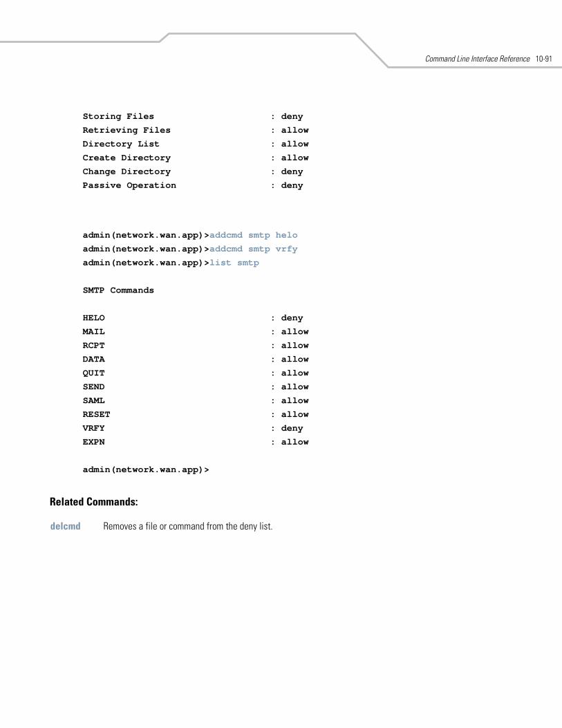
Command Line Interface Reference 10-91
Storing Files : deny
Retrieving Files : allow
Directory List : allow
Create Directory : allow
Change Directory : deny
Passive Operation : deny
admin(network.wan.app)>addcmd smtp helo
admin(network.wan.app)>addcmd smtp vrfy
admin(network.wan.app)>list smtp
SMTP Commands
HELO : deny
MAIL : allow
RCPT : allow
DATA : allow
QUIT : allow
SEND : allow
SAML : allow
RESET : allow
VRFY : deny
EXPN : allow
admin(network.wan.app)>
Related Commands:
delcmd Removes a file or command from the deny list.
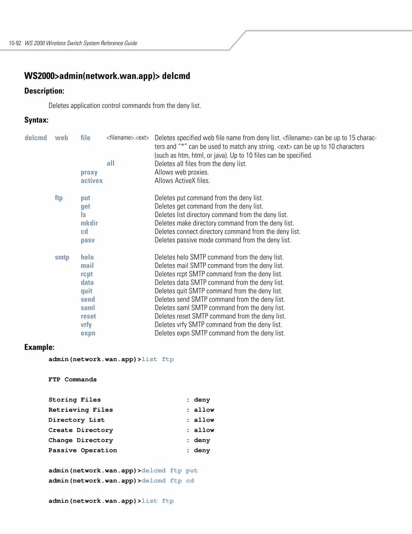
WS 2000 Wireless Switch System Reference Guide10-92
WS2000>admin(network.wan.app)> delcmd
Description:
Deletes application control commands from the deny list.
Syntax:
Example:admin(network.wan.app)>list ftp
FTP Commands
Storing Files : deny
Retrieving Files : allow
Directory List : allow
Create Directory : allow
Change Directory : deny
Passive Operation : deny
admin(network.wan.app)>delcmd ftp put
admin(network.wan.app)>delcmd ftp cd
admin(network.wan.app)>list ftp
delcmd web file <filename>.<ext> Deletes specified web file name from deny list. <filename> can be up to 15 charac-ters and “*” can be used to match any string. <ext> can be up to 10 characters (such as htm, html, or java). Up to 10 files can be specified.
all Deletes all files from the deny list.proxy Allows web proxies.activex Allows ActiveX files.
ftp put Deletes put command from the deny list. get Deletes get command from the deny list. ls Deletes list directory command from the deny list. mkdir Deletes make directory command from the deny list. cd Deletes connect directory command from the deny list. pasv Deletes passive mode command from the deny list.
smtp helo Deletes helo SMTP command from the deny list. mail Deletes mail SMTP command from the deny list.rcpt Deletes rcpt SMTP command from the deny list.data Deletes data SMTP command from the deny list.quit Deletes quit SMTP command from the deny list.send Deletes send SMTP command from the deny list.saml Deletes saml SMTP command from the deny list.reset Deletes reset SMTP command from the deny list.vrfy Deletes vrfy SMTP command from the deny list.expn Deletes expn SMTP command from the deny list.
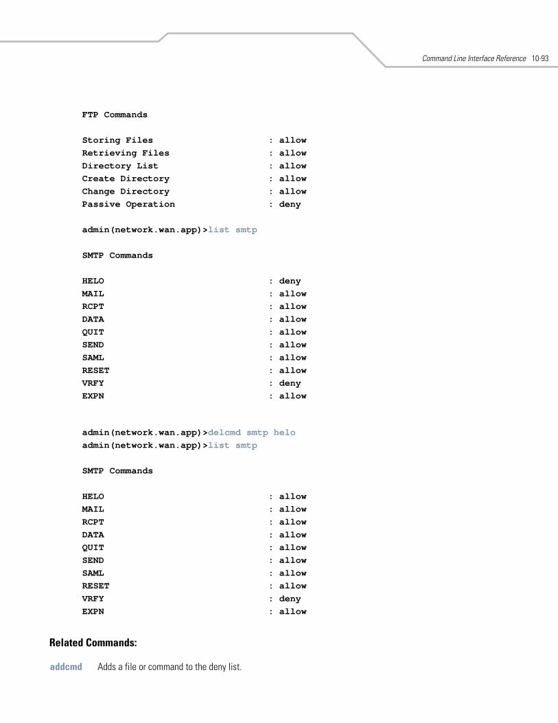
Command Line Interface Reference 10-93
FTP Commands
Storing Files : allow Retrieving Files : allow Directory List : allow Create Directory : allow Change Directory : allow Passive Operation : deny
admin(network.wan.app)>list smtp
SMTP Commands
HELO : deny MAIL : allow RCPT : allow DATA : allow QUIT : allow SEND : allow SAML : allow RESET : allow VRFY : deny EXPN : allow
admin(network.wan.app)>delcmd smtp helo admin(network.wan.app)>list smtp
SMTP Commands
HELO : allow MAIL : allow RCPT : allow DATA : allow QUIT : allow SEND : allow SAML : allow RESET : allow VRFY : deny EXPN : allow
Related Commands:
addcmd Adds a file or command to the deny list.
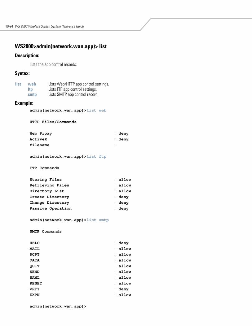
WS 2000 Wireless Switch System Reference Guide10-94
WS2000>admin(network.wan.app)> list
Description:
Lists the app control records.
Syntax:
Example:admin(network.wan.app)>list web
HTTP Files/Commands
Web Proxy : deny ActiveX : deny filename :
admin(network.wan.app)>list ftp
FTP Commands
Storing Files : allow Retrieving Files : allow Directory List : allow Create Directory : deny Change Directory : deny Passive Operation : deny
admin(network.wan.app)>list smtp
SMTP Commands
HELO : deny MAIL : allow RCPT : allow DATA : allow QUIT : allow SEND : allow SAML : allow RESET : allow VRFY : deny EXPN : allow
admin(network.wan.app)>
list web Lists Web/HTTP app control settings.ftp Lists FTP app control settings. smtp Lists SMTP app control record.
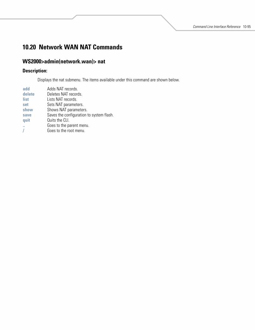
Command Line Interface Reference 10-95
10.20 Network WAN NAT Commands
WS2000>admin(network.wan)> nat
Description:
Displays the nat submenu. The items available under this command are shown below.
add Adds NAT records.delete Deletes NAT records.list Lists NAT records.set Sets NAT parameters. show Shows NAT parameters. save Saves the configuration to system flash.quit Quits the CLI. .. Goes to the parent menu./ Goes to the root menu.
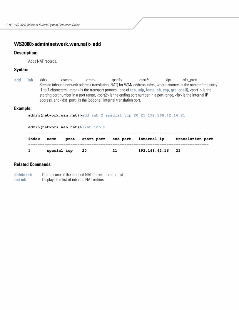
WS 2000 Wireless Switch System Reference Guide10-96
WS2000>admin(network.wan.nat)> add
Description:
Adds NAT records.
Syntax:
Example: admin(network.wan.nat)>add inb 2 special tcp 20 21 192.168.42.16 21
admin(network.wan.nat)>list inb 2
-----------------------------------------------------------------------------
index name prot start port end port internal ip translation port
-----------------------------------------------------------------------------
1 special tcp 20 21 192.168.42.16 21
Related Commands:
add inb <idx> <name> <tran> <port1> <port2> <ip> <dst_port>Sets an inbound network address translation (NAT) for WAN address <idx>, where <name> is the name of the entry (1 to 7 characters), <tran> is the transport protocol (one of tcp, udp, icmp, ah, esp, gre, or all), <port1> is the starting port number in a port range, <port2> is the ending port number in a port range, <ip> is the internal IP address, and <dst_port> is the (optional) internal translation port.
delete inb Deletes one of the inbound NAT entries from the list. list inb Displays the list of inbound NAT entries.
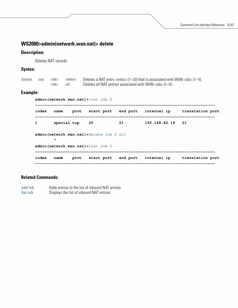
Command Line Interface Reference 10-97
WS2000>admin(network.wan.nat)> delete
Description:
Deletes NAT records.
Syntax:
Example:admin(network.wan.nat)>list inb 2
-----------------------------------------------------------------------------
index name prot start port end port internal ip translation port
-----------------------------------------------------------------------------
1 special tcp 20 21 192.168.42.16 21
admin(network.wan.nat)>delete inb 2 all
^
admin(network.wan.nat)>list inb 2
-----------------------------------------------------------------------------
index name prot start port end port internal ip translation port
-----------------------------------------------------------------------------
Related Commands:
delete inb <idx> <entry> Deletes a NAT entry <entry> (1–20) that is associated with WAN <idx> (1–8).<idx> all Deletes all NAT entries associated with WAN <idx> (1–8).
add inb Adds entries to the list of inbound NAT entries.list inb Displays the list of inbound NAT entries.
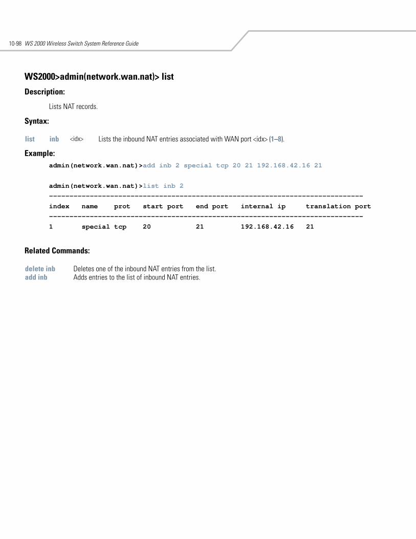
WS 2000 Wireless Switch System Reference Guide10-98
WS2000>admin(network.wan.nat)> list
Description:
Lists NAT records.
Syntax:
Example: admin(network.wan.nat)>add inb 2 special tcp 20 21 192.168.42.16 21
admin(network.wan.nat)>list inb 2
-----------------------------------------------------------------------------
index name prot start port end port internal ip translation port
-----------------------------------------------------------------------------
1 special tcp 20 21 192.168.42.16 21
Related Commands:
list inb <idx> Lists the inbound NAT entries associated with WAN port <idx> (1–8).
delete inb Deletes one of the inbound NAT entries from the list. add inb Adds entries to the list of inbound NAT entries.
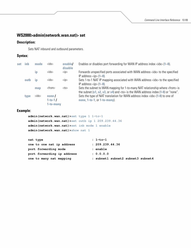
Command Line Interface Reference 10-99
WS2000>admin(network.wan.nat)> set
Description:
Sets NAT inbound and outbound parameters.
Syntax:
Example: admin(network.wan.nat)>set type 1 1-to-1
admin(network.wan.nat)>set outb ip 1 209.239.44.36
admin(network.wan.nat)>set inb mode 1 enable
admin(network.wan.nat)>show nat 1
nat type : 1-to-1
one to one nat ip address : 209.239.44.36
port forwarding mode : enable
port forwarding ip address : 0.0.0.0
one to many nat mapping : subnet1 subnet2 subnet3 subnet4
set inb mode <idx> enable/disable
Enables or disables port forwarding for WAN IP address index <idx> (1–8).
ip <idx> <ip> Forwards unspecified ports associated with WAN address <idx> to the specified IP address <ip> (1–8).
outb ip <idx> <ip> Sets 1-to-1 NAT IP mapping associated with WAN address <idx> to the specified IP address <ip> (1–8).
map <from> <to> Sets the subnet to WAN mapping for 1-to-many NAT relationship where <from> is the subnet (s1, s2, s3, or s4) and <to> is the WAN address index (1-8) or “none”.
type <idx> none /1-to-1 /1-to-many
Sets the type of NAT translation for WAN address index <idx> (1-8) to one of none, 1-to-1, or 1-to-many).
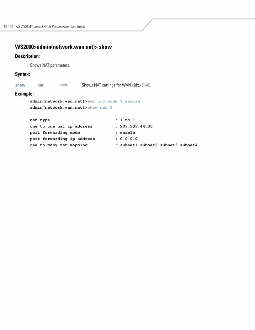
WS 2000 Wireless Switch System Reference Guide10-100
WS2000>admin(network.wan.nat)> show
Description:
Shows NAT parameters.
Syntax:
Example: admin(network.wan.nat)>set inb mode 1 enable
admin(network.wan.nat)>show nat 1
nat type : 1-to-1
one to one nat ip address : 209.239.44.36
port forwarding mode : enable
port forwarding ip address : 0.0.0.0
one to many nat mapping : subnet1 subnet2 subnet3 subnet4
show nat <idx> Shows NAT settings for WAN <idx> (1–8).
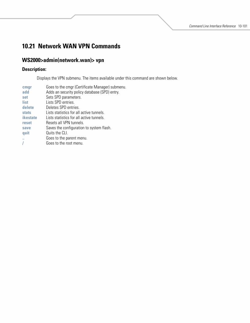
Command Line Interface Reference 10-101
10.21 Network WAN VPN Commands
WS2000>admin(network.wan)> vpn
Description:
Displays the VPN submenu. The items available under this command are shown below.
cmgr Goes to the cmgr (Certificate Manager) submenu. add Adds an security policy database (SPD) entry. set Sets SPD parameters.list Lists SPD entries.delete Deletes SPD entries.stats Lists statistics for all active tunnels.ikestate Lists statistics for all active tunnels.reset Resets all VPN tunnels. save Saves the configuration to system flash.quit Quits the CLI. .. Goes to the parent menu./ Goes to the root menu.
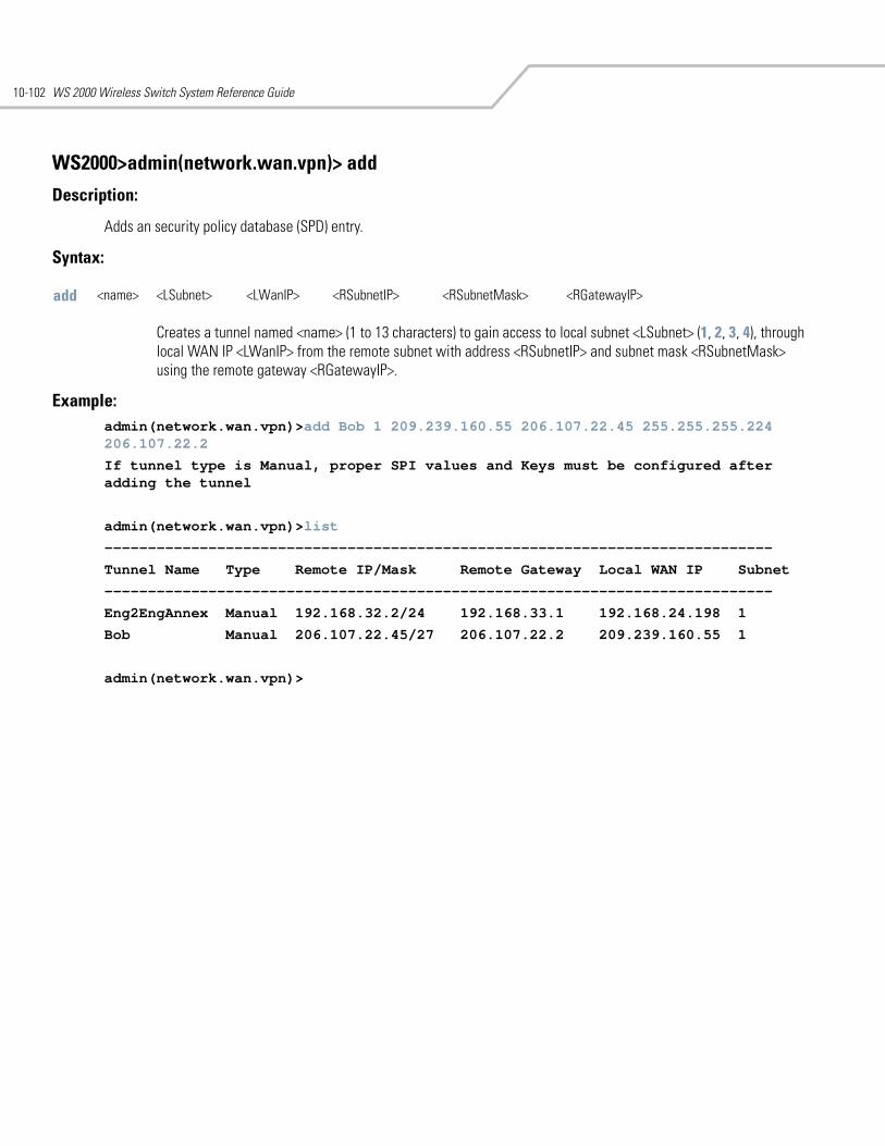
WS 2000 Wireless Switch System Reference Guide10-102
WS2000>admin(network.wan.vpn)> add
Description:
Adds an security policy database (SPD) entry.
Syntax:
Example: admin(network.wan.vpn)>add Bob 1 209.239.160.55 206.107.22.45 255.255.255.224 206.107.22.2
If tunnel type is Manual, proper SPI values and Keys must be configured after adding the tunnel
admin(network.wan.vpn)>list
-----------------------------------------------------------------------------
Tunnel Name Type Remote IP/Mask Remote Gateway Local WAN IP Subnet
-----------------------------------------------------------------------------
Eng2EngAnnex Manual 192.168.32.2/24 192.168.33.1 192.168.24.198 1
Bob Manual 206.107.22.45/27 206.107.22.2 209.239.160.55 1
admin(network.wan.vpn)>
add <name> <LSubnet> <LWanIP> <RSubnetIP> <RSubnetMask> <RGatewayIP>
Creates a tunnel named <name> (1 to 13 characters) to gain access to local subnet <LSubnet> (1, 2, 3, 4), through local WAN IP <LWanIP> from the remote subnet with address <RSubnetIP> and subnet mask <RSubnetMask> using the remote gateway <RGatewayIP>.
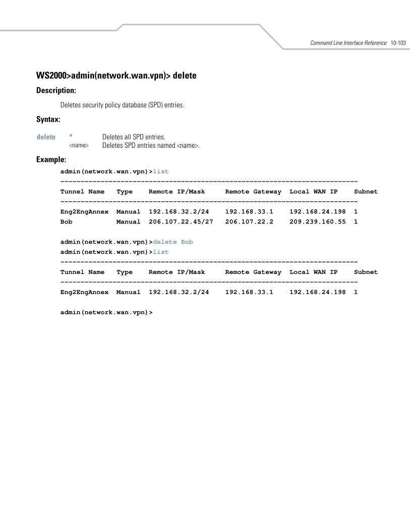
Command Line Interface Reference 10-103
WS2000>admin(network.wan.vpn)> delete
Description:
Deletes security policy database (SPD) entries.
Syntax:
Example: admin(network.wan.vpn)>list
--------------------------------------------------------------------------
Tunnel Name Type Remote IP/Mask Remote Gateway Local WAN IP Subnet
--------------------------------------------------------------------------
Eng2EngAnnex Manual 192.168.32.2/24 192.168.33.1 192.168.24.198 1
Bob Manual 206.107.22.45/27 206.107.22.2 209.239.160.55 1
admin(network.wan.vpn)>delete Bob
admin(network.wan.vpn)>list
--------------------------------------------------------------------------
Tunnel Name Type Remote IP/Mask Remote Gateway Local WAN IP Subnet
--------------------------------------------------------------------------
Eng2EngAnnex Manual 192.168.32.2/24 192.168.33.1 192.168.24.198 1
admin(network.wan.vpn)>
delete * Deletes all SPD entries.<name> Deletes SPD entries named <name>.
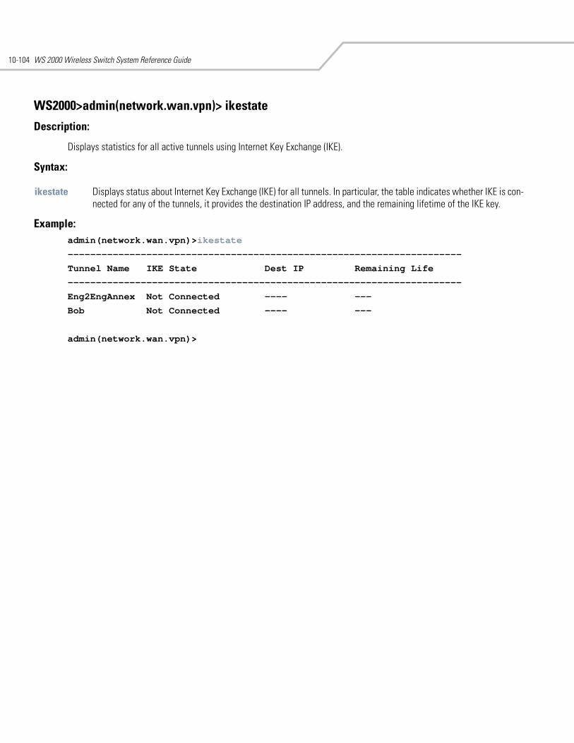
WS 2000 Wireless Switch System Reference Guide10-104
WS2000>admin(network.wan.vpn)> ikestate
Description:
Displays statistics for all active tunnels using Internet Key Exchange (IKE).
Syntax:
Example: admin(network.wan.vpn)>ikestate
----------------------------------------------------------------------
Tunnel Name IKE State Dest IP Remaining Life
----------------------------------------------------------------------
Eng2EngAnnex Not Connected ---- ---
Bob Not Connected ---- ---
admin(network.wan.vpn)>
ikestate Displays status about Internet Key Exchange (IKE) for all tunnels. In particular, the table indicates whether IKE is con-nected for any of the tunnels, it provides the destination IP address, and the remaining lifetime of the IKE key.
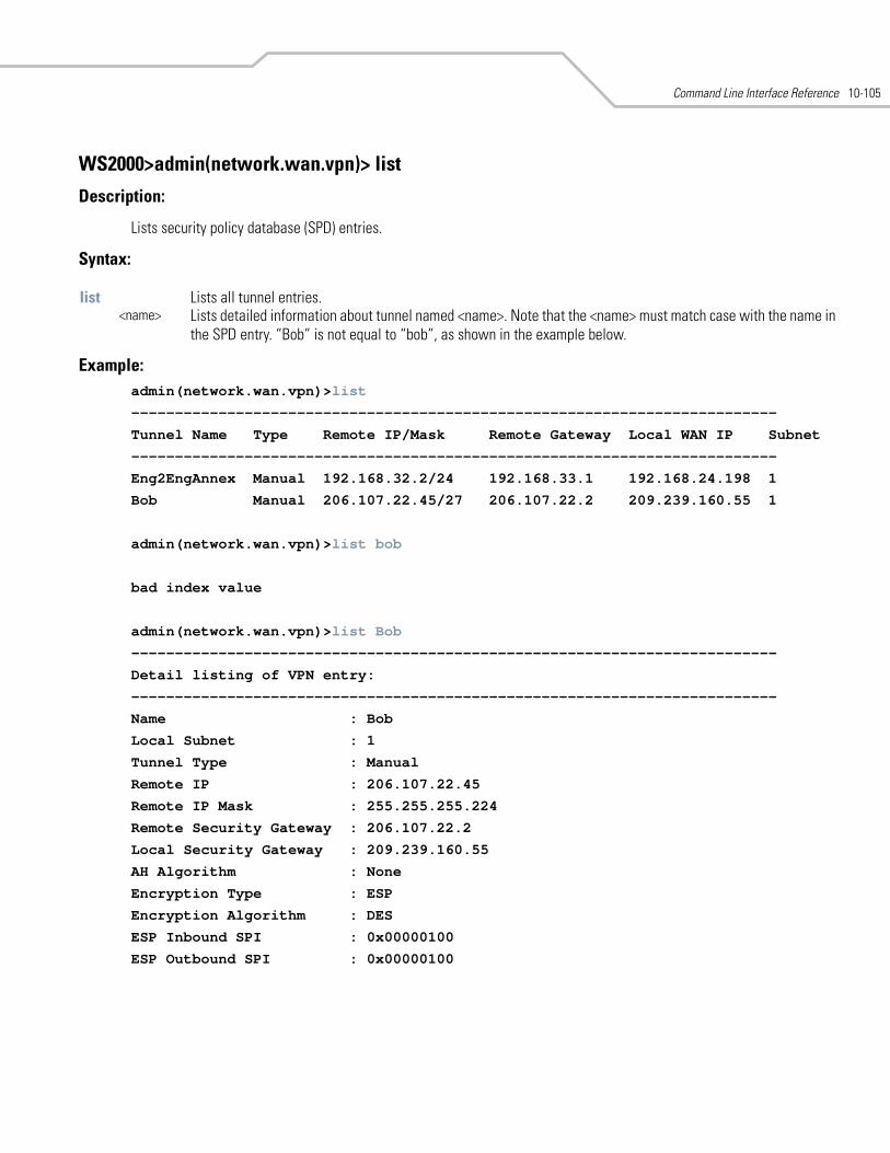
Command Line Interface Reference 10-105
WS2000>admin(network.wan.vpn)> list
Description:
Lists security policy database (SPD) entries.
Syntax:
Example:admin(network.wan.vpn)>list
--------------------------------------------------------------------------
Tunnel Name Type Remote IP/Mask Remote Gateway Local WAN IP Subnet
--------------------------------------------------------------------------
Eng2EngAnnex Manual 192.168.32.2/24 192.168.33.1 192.168.24.198 1
Bob Manual 206.107.22.45/27 206.107.22.2 209.239.160.55 1
admin(network.wan.vpn)>list bob
bad index value
admin(network.wan.vpn)>list Bob
--------------------------------------------------------------------------
Detail listing of VPN entry:
--------------------------------------------------------------------------
Name : Bob
Local Subnet : 1
Tunnel Type : Manual
Remote IP : 206.107.22.45
Remote IP Mask : 255.255.255.224
Remote Security Gateway : 206.107.22.2
Local Security Gateway : 209.239.160.55
AH Algorithm : None
Encryption Type : ESP
Encryption Algorithm : DES
ESP Inbound SPI : 0x00000100
ESP Outbound SPI : 0x00000100
list Lists all tunnel entries.<name> Lists detailed information about tunnel named <name>. Note that the <name> must match case with the name in
the SPD entry. “Bob” is not equal to “bob”, as shown in the example below.
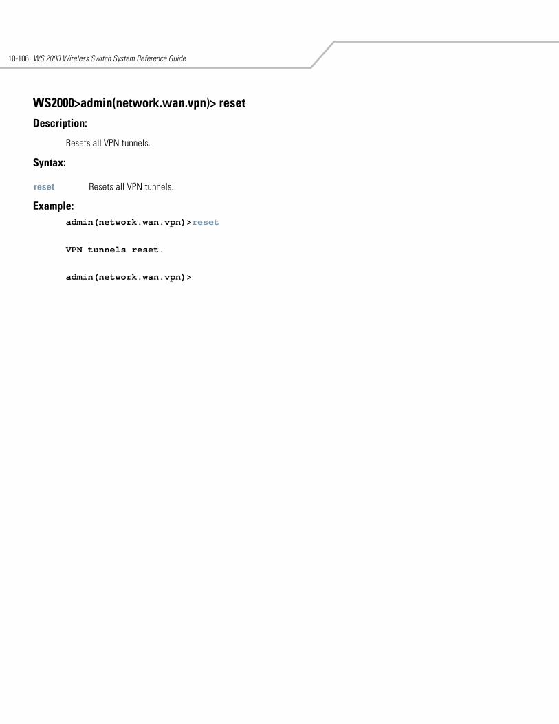
WS 2000 Wireless Switch System Reference Guide10-106
WS2000>admin(network.wan.vpn)> reset
Description:
Resets all VPN tunnels.
Syntax:
Example: admin(network.wan.vpn)>reset
VPN tunnels reset.
admin(network.wan.vpn)>
reset Resets all VPN tunnels.
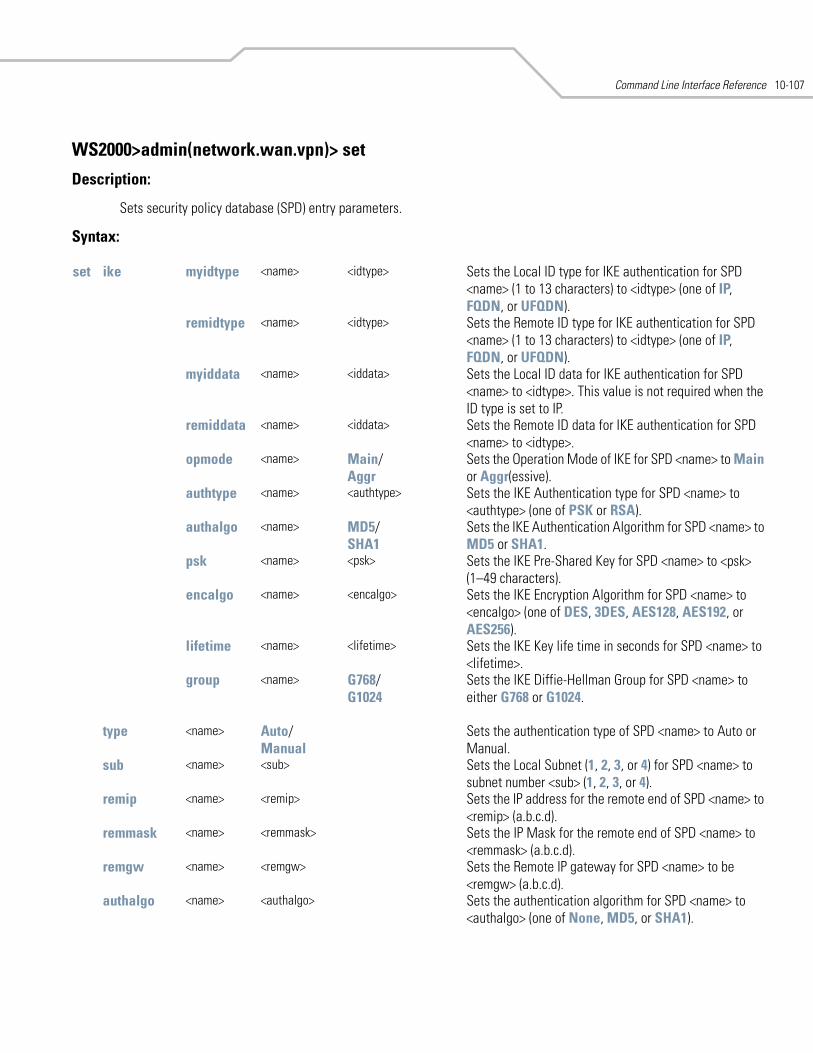
Command Line Interface Reference 10-107
WS2000>admin(network.wan.vpn)> set
Description:
Sets security policy database (SPD) entry parameters.
Syntax:
set ike myidtype <name> <idtype> Sets the Local ID type for IKE authentication for SPD <name> (1 to 13 characters) to <idtype> (one of IP, FQDN, or UFQDN).
remidtype <name> <idtype> Sets the Remote ID type for IKE authentication for SPD <name> (1 to 13 characters) to <idtype> (one of IP, FQDN, or UFQDN).
myiddata <name> <iddata> Sets the Local ID data for IKE authentication for SPD <name> to <idtype>. This value is not required when the ID type is set to IP.
remiddata <name> <iddata> Sets the Remote ID data for IKE authentication for SPD <name> to <idtype>.
opmode <name> Main/Aggr
Sets the Operation Mode of IKE for SPD <name> to Main or Aggr(essive).
authtype <name> <authtype> Sets the IKE Authentication type for SPD <name> to <authtype> (one of PSK or RSA).
authalgo <name> MD5/SHA1
Sets the IKE Authentication Algorithm for SPD <name> to MD5 or SHA1.
psk <name> <psk> Sets the IKE Pre-Shared Key for SPD <name> to <psk> (1–49 characters).
encalgo <name> <encalgo> Sets the IKE Encryption Algorithm for SPD <name> to <encalgo> (one of DES, 3DES, AES128, AES192, or AES256).
lifetime <name> <lifetime> Sets the IKE Key life time in seconds for SPD <name> to <lifetime>.
group <name> G768/G1024
Sets the IKE Diffie-Hellman Group for SPD <name> to either G768 or G1024.
type <name> Auto/Manual
Sets the authentication type of SPD <name> to Auto or Manual.
sub <name> <sub> Sets the Local Subnet (1, 2, 3, or 4) for SPD <name> to subnet number <sub> (1, 2, 3, or 4).
remip <name> <remip> Sets the IP address for the remote end of SPD <name> to <remip> (a.b.c.d).
remmask <name> <remmask> Sets the IP Mask for the remote end of SPD <name> to <remmask> (a.b.c.d).
remgw <name> <remgw> Sets the Remote IP gateway for SPD <name> to be <remgw> (a.b.c.d).
authalgo <name> <authalgo> Sets the authentication algorithm for SPD <name> to <authalgo> (one of None, MD5, or SHA1).
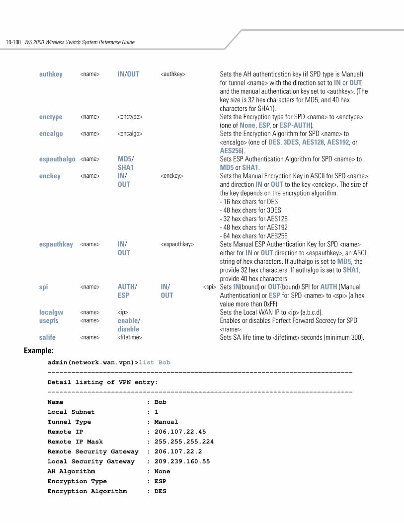
WS 2000 Wireless Switch System Reference Guide10-108
Example: admin(network.wan.vpn)>list Bob
-----------------------------------------------------------------------------
Detail listing of VPN entry:
-----------------------------------------------------------------------------
Name : Bob
Local Subnet : 1
Tunnel Type : Manual
Remote IP : 206.107.22.45
Remote IP Mask : 255.255.255.224
Remote Security Gateway : 206.107.22.2
Local Security Gateway : 209.239.160.55
AH Algorithm : None
Encryption Type : ESP
Encryption Algorithm : DES
authkey <name> IN/OUT <authkey> Sets the AH authentication key (if SPD type is Manual) for tunnel <name> with the direction set to IN or OUT, and the manual authentication key set to <authkey>. (The key size is 32 hex characters for MD5, and 40 hex characters for SHA1).
enctype <name> <enctype> Sets the Encryption type for SPD <name> to <enctype> (one of None, ESP, or ESP-AUTH).
encalgo <name> <encalgo> Sets the Encryption Algorithm for SPD <name> to <encalgo> (one of DES, 3DES, AES128, AES192, or AES256).
espauthalgo <name> MD5/SHA1
Sets ESP Authentication Algorithm for SPD <name> to MD5 or SHA1.
enckey <name> IN/OUT
<enckey> Sets the Manual Encryption Key in ASCII for SPD <name> and direction IN or OUT to the key <enckey>. The size of the key depends on the encryption algorithm.- 16 hex chars for DES - 48 hex chars for 3DES - 32 hex chars for AES128 - 48 hex chars for AES192 - 64 hex chars for AES256
espauthkey <name> IN/OUT
<espauthkey> Sets Manual ESP Authentication Key for SPD <name> either for IN or OUT direction to <espauthkey>, an ASCII string of hex characters. If authalgo is set to MD5, the provide 32 hex characters. If authalgo is set to SHA1, provide 40 hex characters.
spi <name> AUTH/ESP
IN/OUT
<spi> Sets IN(bound) or OUT(bound) SPI for AUTH (Manual Authentication) or ESP for SPD <name> to <spi> (a hex value more than 0xFF).
localgw <name> <ip> Sets the Local WAN IP to <ip> (a.b.c.d). usepfs <name> enable/
disableEnables or disables Perfect Forward Secrecy for SPD <name>.
salife <name> <lifetime> Sets SA life time to <lifetime> seconds (minimum 300).
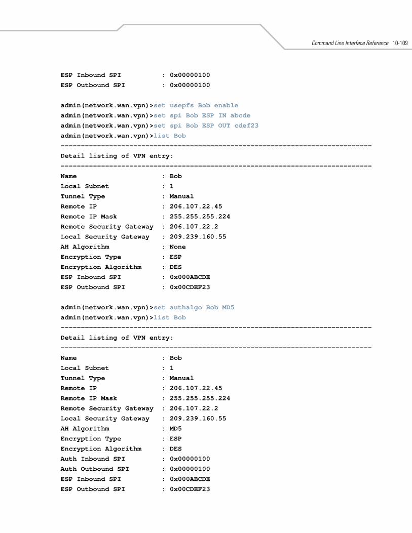
Command Line Interface Reference 10-109
ESP Inbound SPI : 0x00000100
ESP Outbound SPI : 0x00000100
admin(network.wan.vpn)>set usepfs Bob enable
admin(network.wan.vpn)>set spi Bob ESP IN abcde
admin(network.wan.vpn)>set spi Bob ESP OUT cdef23
admin(network.wan.vpn)>list Bob
-----------------------------------------------------------------------------
Detail listing of VPN entry:
-----------------------------------------------------------------------------
Name : Bob
Local Subnet : 1
Tunnel Type : Manual
Remote IP : 206.107.22.45
Remote IP Mask : 255.255.255.224
Remote Security Gateway : 206.107.22.2
Local Security Gateway : 209.239.160.55
AH Algorithm : None
Encryption Type : ESP
Encryption Algorithm : DES
ESP Inbound SPI : 0x000ABCDE
ESP Outbound SPI : 0x00CDEF23
admin(network.wan.vpn)>set authalgo Bob MD5
admin(network.wan.vpn)>list Bob
-----------------------------------------------------------------------------
Detail listing of VPN entry:
-----------------------------------------------------------------------------
Name : Bob
Local Subnet : 1
Tunnel Type : Manual
Remote IP : 206.107.22.45
Remote IP Mask : 255.255.255.224
Remote Security Gateway : 206.107.22.2
Local Security Gateway : 209.239.160.55
AH Algorithm : MD5
Encryption Type : ESP
Encryption Algorithm : DES
Auth Inbound SPI : 0x00000100
Auth Outbound SPI : 0x00000100
ESP Inbound SPI : 0x000ABCDE
ESP Outbound SPI : 0x00CDEF23
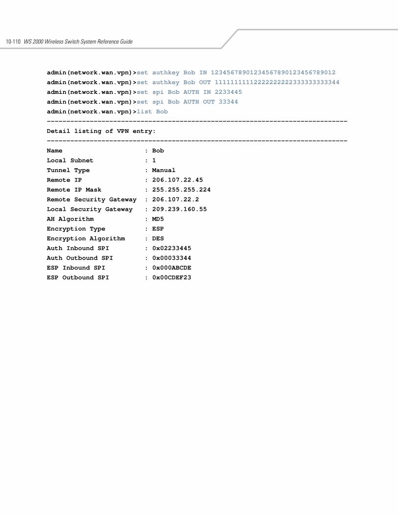
WS 2000 Wireless Switch System Reference Guide10-110
admin(network.wan.vpn)>set authkey Bob IN 12345678901234567890123456789012
admin(network.wan.vpn)>set authkey Bob OUT 11111111112222222222333333333344
admin(network.wan.vpn)>set spi Bob AUTH IN 2233445
admin(network.wan.vpn)>set spi Bob AUTH OUT 33344
admin(network.wan.vpn)>list Bob
-----------------------------------------------------------------------------
Detail listing of VPN entry:
-----------------------------------------------------------------------------
Name : Bob
Local Subnet : 1
Tunnel Type : Manual
Remote IP : 206.107.22.45
Remote IP Mask : 255.255.255.224
Remote Security Gateway : 206.107.22.2
Local Security Gateway : 209.239.160.55
AH Algorithm : MD5
Encryption Type : ESP
Encryption Algorithm : DES
Auth Inbound SPI : 0x02233445
Auth Outbound SPI : 0x00033344
ESP Inbound SPI : 0x000ABCDE
ESP Outbound SPI : 0x00CDEF23
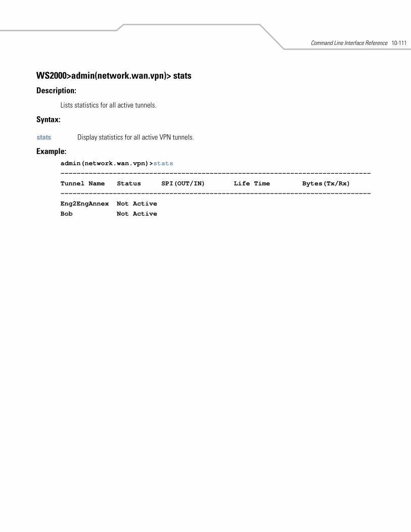
Command Line Interface Reference 10-111
WS2000>admin(network.wan.vpn)> stats
Description:
Lists statistics for all active tunnels.
Syntax:
Example: admin(network.wan.vpn)>stats
-----------------------------------------------------------------------------
Tunnel Name Status SPI(OUT/IN) Life Time Bytes(Tx/Rx)
-----------------------------------------------------------------------------
Eng2EngAnnex Not Active
Bob Not Active
stats Display statistics for all active VPN tunnels.
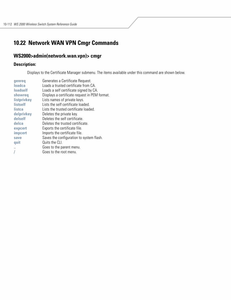
WS 2000 Wireless Switch System Reference Guide10-112
10.22 Network WAN VPN Cmgr Commands
WS2000>admin(network.wan.vpn)> cmgr
Description:
Displays to the Certificate Manager submenu. The items available under this command are shown below.
genreq Generates a Certificate Request.loadca Loads a trusted certificate from CA.loadself Loads a self certificate signed by CA.showreq Displays a certificate request in PEM format.listprivkey Lists names of private keys.listself Lists the self certificate loaded.listca Lists the trusted certificate loaded.delprivkey Deletes the private key.delself Deletes the self certificate.delca Deletes the trusted certificate.expcert Exports the certificate file.impcert Imports the certificate file.save Saves the configuration to system flash.quit Quits the CLI. .. Goes to the parent menu./ Goes to the root menu.
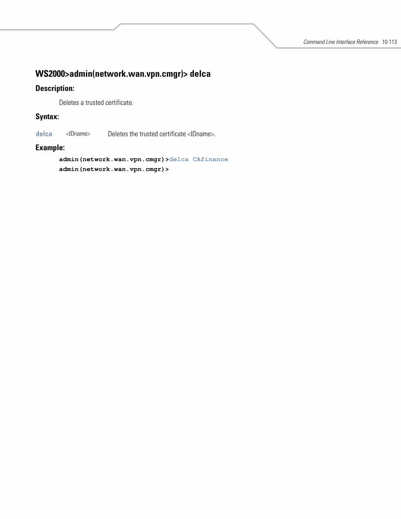
Command Line Interface Reference 10-113
WS2000>admin(network.wan.vpn.cmgr)> delca
Description:
Deletes a trusted certificate.
Syntax:
Example: admin(network.wan.vpn.cmgr)>delca CAfinance
admin(network.wan.vpn.cmgr)>
delca <IDname> Deletes the trusted certificate <IDname>.
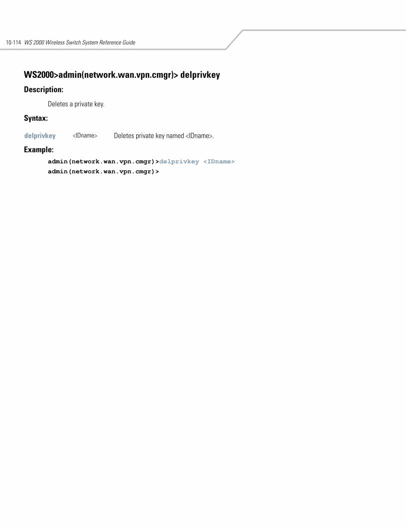
WS 2000 Wireless Switch System Reference Guide10-114
WS2000>admin(network.wan.vpn.cmgr)> delprivkey
Description:
Deletes a private key.
Syntax:
Example: admin(network.wan.vpn.cmgr)>delprivkey <IDname>
admin(network.wan.vpn.cmgr)>
delprivkey <IDname> Deletes private key named <IDname>.
Command Line Interface Reference 10-115
WS2000>admin(network.wan.vpn.cmgr)> delself
Description:
Deletes a self certificate.
Syntax:
Example: admin(network.wan.vpn.cmgr)>delself<IDname>
admin(network.wan.vpn.cmgr)>
delself <IDname> Deletes the self certificate named <IDname>.

WS 2000 Wireless Switch System Reference Guide10-116
WS2000>admin(network.wan.vpn.cmgr)> expcert
Description:
Exports the certificate file.
Syntax:
Example: admin(system.config)>set server 192.168.22.12
admin(system.config)>set user myadmin
admin(system.config)>set passwd
admin(network.wan.vpn.cmgr)>expcert ftp mycertificate
admin(network.wan.vpn.cmgr)>
Related Commands:
expcert ftp / tftp <file name> Exports the certificate with specified filename <file name> by either ftp or tftp. The tftp or ftp options for this file transfer will use the settings for the configuration file settings. See System Configuration Commands for information on how to set the tftp/ftp options.
impcert Imports a certificate.
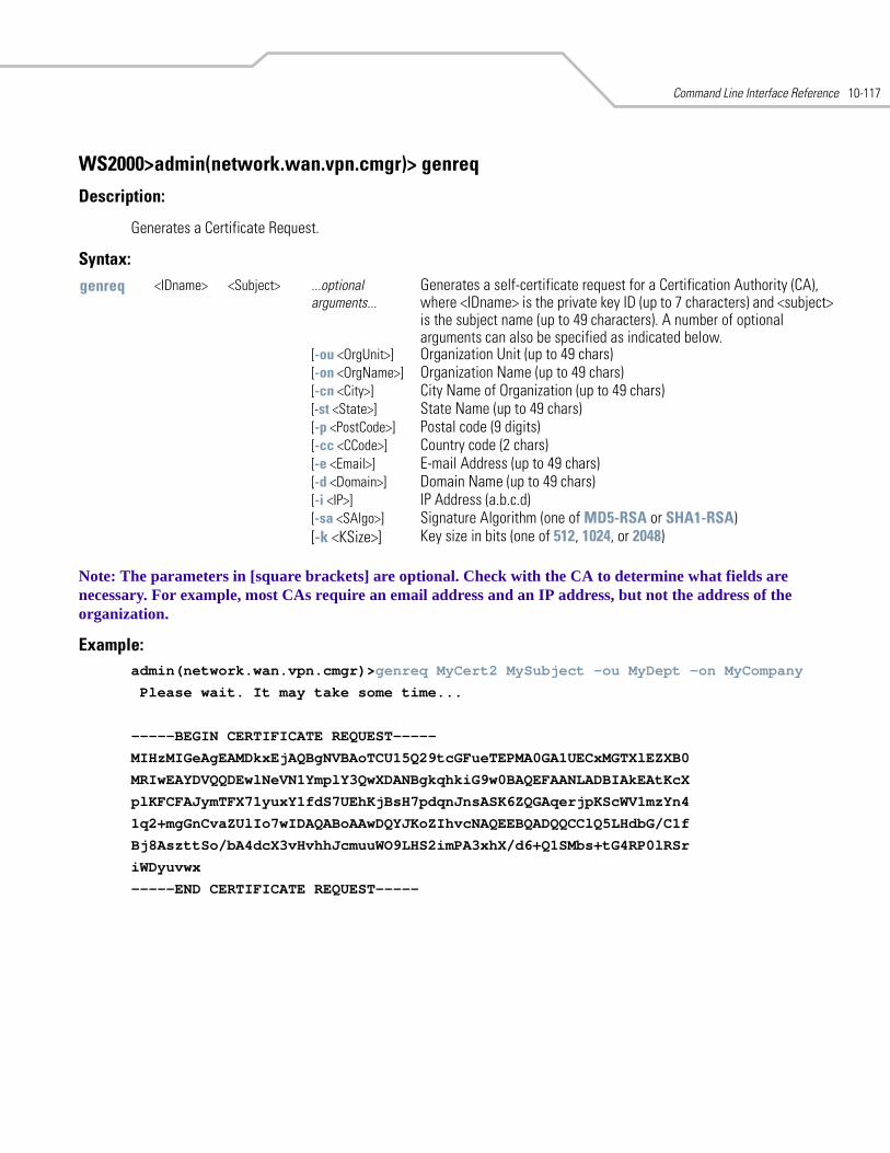
Command Line Interface Reference 10-117
WS2000>admin(network.wan.vpn.cmgr)> genreq
Description:
Generates a Certificate Request.
Syntax:
Note: The parameters in [square brackets] are optional. Check with the CA to determine what fields are necessary. For example, most CAs require an email address and an IP address, but not the address of the organization.
Example:admin(network.wan.vpn.cmgr)>genreq MyCert2 MySubject -ou MyDept -on MyCompany
Please wait. It may take some time...
-----BEGIN CERTIFICATE REQUEST-----
MIHzMIGeAgEAMDkxEjAQBgNVBAoTCU15Q29tcGFueTEPMA0GA1UECxMGTXlEZXB0
MRIwEAYDVQQDEwlNeVN1YmplY3QwXDANBgkqhkiG9w0BAQEFAANLADBIAkEAtKcX
plKFCFAJymTFX71yuxY1fdS7UEhKjBsH7pdqnJnsASK6ZQGAqerjpKScWV1mzYn4
1q2+mgGnCvaZUlIo7wIDAQABoAAwDQYJKoZIhvcNAQEEBQADQQCClQ5LHdbG/C1f
Bj8AszttSo/bA4dcX3vHvhhJcmuuWO9LHS2imPA3xhX/d6+Q1SMbs+tG4RP0lRSr
iWDyuvwx
-----END CERTIFICATE REQUEST-----
genreq <IDname> <Subject> ...optional arguments...
Generates a self-certificate request for a Certification Authority (CA), where <IDname> is the private key ID (up to 7 characters) and <subject> is the subject name (up to 49 characters). A number of optional arguments can also be specified as indicated below.
[-ou <OrgUnit>] Organization Unit (up to 49 chars) [-on <OrgName>] Organization Name (up to 49 chars) [-cn <City>] City Name of Organization (up to 49 chars)[-st <State>] State Name (up to 49 chars)[-p <PostCode>] Postal code (9 digits) [-cc <CCode>] Country code (2 chars)[-e <Email>] E-mail Address (up to 49 chars) [-d <Domain>] Domain Name (up to 49 chars)[-i <IP>] IP Address (a.b.c.d) [-sa <SAlgo>] Signature Algorithm (one of MD5-RSA or SHA1-RSA) [-k <KSize>] Key size in bits (one of 512, 1024, or 2048)
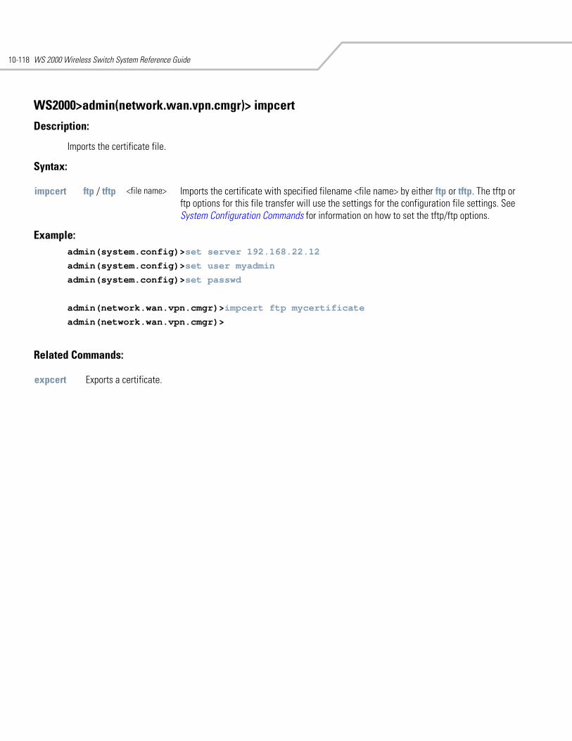
WS 2000 Wireless Switch System Reference Guide10-118
WS2000>admin(network.wan.vpn.cmgr)> impcert
Description:
Imports the certificate file.
Syntax:
Example: admin(system.config)>set server 192.168.22.12
admin(system.config)>set user myadmin
admin(system.config)>set passwd
admin(network.wan.vpn.cmgr)>impcert ftp mycertificate
admin(network.wan.vpn.cmgr)>
Related Commands:
impcert ftp / tftp <file name> Imports the certificate with specified filename <file name> by either ftp or tftp. The tftp or ftp options for this file transfer will use the settings for the configuration file settings. See System Configuration Commands for information on how to set the tftp/ftp options.
expcert Exports a certificate.
Command Line Interface Reference 10-119
WS2000>admin(network.wan.vpn.cmgr)> listca
Description:
Lists the loaded trusted certificate.
Syntax:
Example:admin(network.wan.vpn.cmgr)>listca
Trusted Certificate List:
listca Lists the loaded trusted certificates.
WS 2000 Wireless Switch System Reference Guide10-120
WS2000>admin(network.wan.vpn.cmgr)> listprivkey
Description:
Lists the names of private keys.
Syntax:
Example: admin(network.wan.vpn.cmgr)>listprivkey
-----------------------------------------------------------------------------
Private Key Name Certificate Associated
-----------------------------------------------------------------------------
listprivkey Lists all private keys.
Command Line Interface Reference 10-121
WS2000>admin(network.wan.vpn.cmgr)> listself
Description:
Lists the loaded self certificates.
Syntax:
Example:admin(network.wan.vpn.cmgr)>listself
Self Certificate List:
listself Lists all self certificates that are loaded.
WS 2000 Wireless Switch System Reference Guide10-122
WS2000>admin(network.wan.vpn.cmgr)> loadca
Description:
Loads a trusted certificate from the Certificate Authority.
Syntax:
Example: admin(network.wan.vpn.cmgr)>loadca
Currently Only certificates in PEM format can be uploaded
Paste the certificate:
loadca Loads the trusted certificate (in PEM format) that is pasted into the command line.
Command Line Interface Reference 10-123
WS2000>admin(network.wan.vpn.cmgr)> loadself
Description:
Loads a self certificate signed by the Certificate Authority.
Syntax:
Example:admin(network.wan.vpn.cmgr)>loadself MyCert
Currently Only certificates in PEM format can be uploaded.
Paste the certificate:
loadself <IDname> Loads the self certificate signed by the CA with name <IDname>.
WS 2000 Wireless Switch System Reference Guide10-124
WS2000>admin(network.wan.vpn.cmgr)> showreq
Description:
Displays a certificate request in PEM format.
Syntax:
showreq <IDname> Displays a certificate request named <IDname> generated from the genreq command.
Command Line Interface Reference 10-125
10.23 Network WLAN Commands
WS2000>admin(network)> wlan
Description:
Displays the WLAN submenu. The items available under this command are shown below.
add Adds MU access control list entries.delete Deletes MU access control list entries.list Lists MU access control list entries.rogueap Goes to the rogue AP submenu.set Sets WLAN parameters.show Shows WLAN parameters.save Saves the configuration to system flash.quit Quits the CLI. .. Goes to the parent menu./ Goes to the root menu.
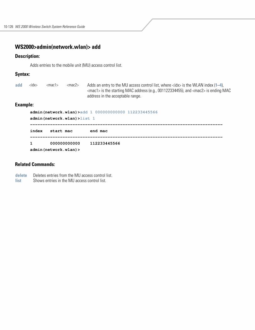
WS 2000 Wireless Switch System Reference Guide10-126
WS2000>admin(network.wlan)> add
Description:
Adds entries to the mobile unit (MU) access control list.
Syntax:
Example:admin(network.wlan)>add 1 000000000000 112233445566
admin(network.wlan)>list 1
-----------------------------------------------------------------------------
index start mac end mac
-----------------------------------------------------------------------------
1 000000000000 112233445566
admin(network.wlan)>
Related Commands:
add <idx> <mac1> <mac2> Adds an entry to the MU access control list, where <idx> is the WLAN index (1–4), <mac1> is the starting MAC address (e.g., 001122334455), and <mac2> is ending MAC address in the acceptable range.
delete Deletes entries from the MU access control list.list Shows entries in the MU access control list.
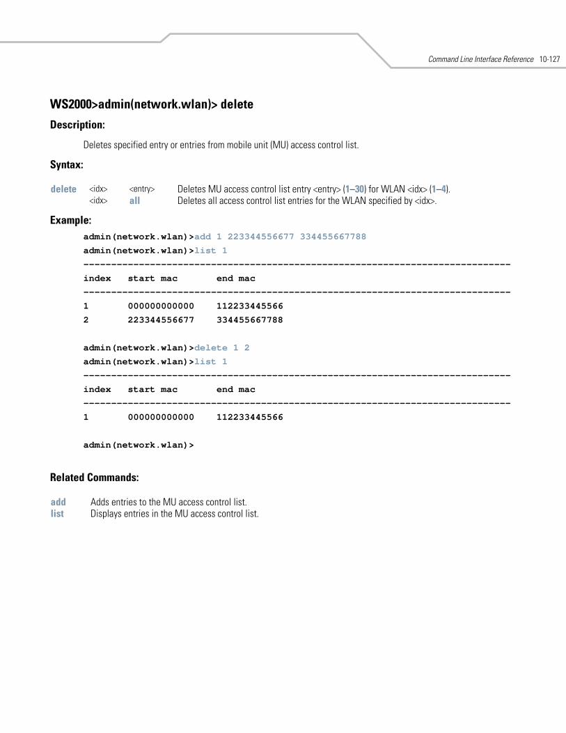
Command Line Interface Reference 10-127
WS2000>admin(network.wlan)> delete
Description:
Deletes specified entry or entries from mobile unit (MU) access control list.
Syntax:
Example: admin(network.wlan)>add 1 223344556677 334455667788
admin(network.wlan)>list 1
-----------------------------------------------------------------------------
index start mac end mac
-----------------------------------------------------------------------------
1 000000000000 112233445566
2 223344556677 334455667788
admin(network.wlan)>delete 1 2
admin(network.wlan)>list 1
-----------------------------------------------------------------------------
index start mac end mac
-----------------------------------------------------------------------------
1 000000000000 112233445566
admin(network.wlan)>
Related Commands:
delete <idx> <entry> Deletes MU access control list entry <entry> (1–30) for WLAN <idx> (1–4).<idx> all Deletes all access control list entries for the WLAN specified by <idx>.
add Adds entries to the MU access control list.list Displays entries in the MU access control list.
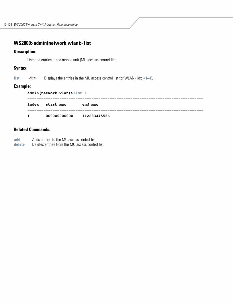
WS 2000 Wireless Switch System Reference Guide10-128
WS2000>admin(network.wlan)> list
Description:
Lists the entries in the mobile unit (MU) access control list.
Syntax:
Example: admin(network.wlan)>list 1
-----------------------------------------------------------------------------
index start mac end mac
-----------------------------------------------------------------------------
1 000000000000 112233445566
Related Commands:
list <idx> Displays the entries in the MU access control list for WLAN <idx> (1–4).
add Adds entries to the MU access control list.delete Deletes entries from the MU access control list.
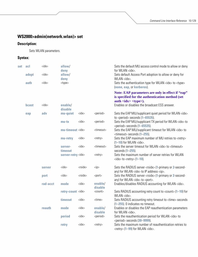
Command Line Interface Reference 10-129
WS2000>admin(network.wlan)> set
Description:
Sets WLAN parameters.
Syntax:
set acl <idx> allow/deny
Sets the default MU access control mode to allow or deny for WLAN <idx>.
adopt <idx> allow/deny
Sets default Access Port adoption to allow or deny for WLAN <idx>.
auth <idx> <type> Sets the authentication type for WLAN <idx> to <type> (none, eap, or kerberos).
Note: EAP parameters are only in effect if “eap” is specified for the authentication method (set auth <idx> <type>).
bcast <idx> enable/disable
Enables or disables the broadcast ESS answer.
eap adv mu-quiet <idx> <period> Sets the EAP MU/supplicant quiet period for WLAN <idx> to <period> seconds (1–65535).
mu-tx <idx> <period> Sets the EAP MU/supplicant TX period for WLAN <idx> to <period> seconds (1–65535).
mu-timeout <idx> <timeout> Sets the EAP MU/supplicant timeout for WLAN <idx> to <timeout> seconds (1–255).
mu-retry <idx> <retry> Sets the EAP maximum number of MU retries to <retry> (1–10) for WLAN <idx>.
server-timeout
<idx> <timeout> Sets the server timeout for WLAN <idx> to <timeout> seconds (1–255).
server-retry <idx> <retry> Sets the maximum number of server retries for WLAN <idx> to <retry> (1–10).
server <idx> <rsidx> <ip> Sets the RADIUS server <rsidx> (1-primary or 2-second-ary) for WLAN <idx> to IP address <ip>.
port <idx> <rsidx> <port> Sets the RADIUS server <rsidx> (1-primary or 2-second-ary) for WLAN <idx> to <port>.
rad-acct mode <idx> enable/disable
Enables/disables RADIUS accounting for WLAN <idx>.
retry-count <idx> <count> Sets RADIUS accounting retry count to <count> (1–10) for WLAN <idx>.
timeout <idx> <time> Sets RADIUS accounting retry timeout to <time> seconds (1–255). 0 indicates no timeout.
reauth mode <idx> enable/disable
Enables or disables the EAP reauthentication parameters for WLAN <idx>.
period <idx> <period> Sets the reauthentication period for WLAN <idx> to <period> seconds (30–9999).
retry <idx> <retry> Sets the maximum number of reauthentication retries to <retry> (1–99) for WLAN <idx>.
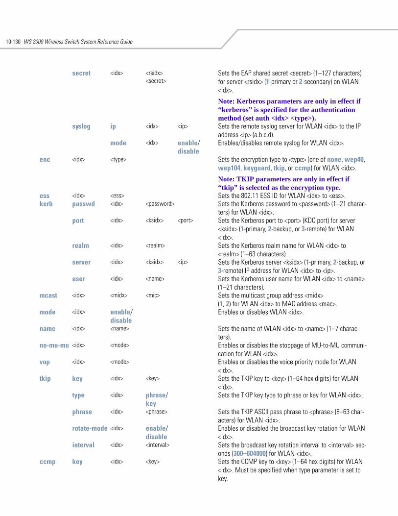
WS 2000 Wireless Switch System Reference Guide10-130
secret <idx> <rsidx> <secret>
Sets the EAP shared secret <secret> (1–127 characters) for server <rsidx> (1-primary or 2-secondary) on WLAN <idx>.
Note: Kerberos parameters are only in effect if “kerberos” is specified for the authentication method (set auth <idx> <type>).
syslog ip <idx> <ip> Sets the remote syslog server for WLAN <idx> to the IP address <ip> (a.b.c.d).
mode <idx> enable/disable
Enables/disables remote syslog for WLAN <idx>.
enc <idx> <type> Sets the encryption type to <type> (one of none, wep40, wep104, keyguard, tkip, or ccmp) for WLAN <idx>.
Note: TKIP parameters are only in effect if “tkip” is selected as the encryption type.
ess <idx> <ess> Sets the 802.11 ESS ID for WLAN <idx> to <ess>.kerb passwd <idx> <password> Sets the Kerberos password to <password> (1–21 charac-
ters) for WLAN <idx>.port <idx> <ksidx> <port> Sets the Kerberos port to <port> (KDC port) for server
<ksidx> (1-primary, 2-backup, or 3-remote) for WLAN <idx>.
realm <idx> <realm> Sets the Kerberos realm name for WLAN <idx> to <realm> (1–63 characters).
server <idx> <ksidx> <ip> Sets the Kerberos server <ksidx> (1-primary, 2-backup, or 3-remote) IP address for WLAN <idx> to <ip>.
user <idx> <name> Sets the Kerberos user name for WLAN <idx> to <name> (1–21 characters).
mcast <idx> <midx> <mic> Sets the multicast group address <midx> (1, 2) for WLAN <idx> to MAC address <mac>.
mode <idx> enable/disable
Enables or disables WLAN <idx>.
name <idx> <name> Sets the name of WLAN <idx> to <name> (1–7 charac-ters).
no-mu-mu <idx> <mode> Enables or disables the stoppage of MU-to-MU communi-cation for WLAN <idx>.
vop <idx> <mode> Enables or disables the voice priority mode for WLAN <idx>.
tkip key <idx> <key> Sets the TKIP key to <key> (1–64 hex digits) for WLAN <idx>.
type <idx> phrase/key
Sets the TKIP key type to phrase or key for WLAN <idx>.
phrase <idx> <phrase> Sets the TKIP ASCII pass phrase to <phrase> (8–63 char-acters) for WLAN <idx>.
rotate-mode <idx> enable/disable
Enables or disabled the broadcast key rotation for WLAN <idx>.
interval <idx> <interval> Sets the broadcast key rotation interval to <interval> sec-onds (300–604800) for WLAN <idx>.
ccmp key <idx> <key> Sets the CCMP key to <key> (1–64 hex digits) for WLAN <idx>. Must be specified when type parameter is set to key.
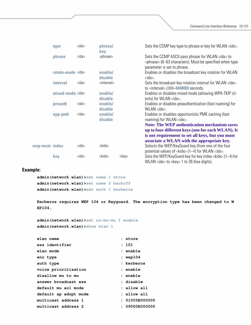
Command Line Interface Reference 10-131
Example:admin(network.wlan)>set name 1 store
admin(network.wlan)>set name 2 backoff
admin(network.wlan)>set auth 1 kerberos
Kerberos requires WEP 104 or Keyguard. The encryption type has been changed to W
EP104.
admin(network.wlan)>set no-mu-mu 1 enable
admin(network.wlan)>show wlan 1
wlan name : store
ess identifier : 101
wlan mode : enable
enc type : wep104
auth type : kerberos
voice prioritization : enable
disallow mu to mu : enable
answer broadcast ess : disable
default mu acl mode : allow all
default ap adopt mode : allow all
multicast address 1 : 01005E000000
multicast address 2 : 09000E000000
type <idx> phrase/key
Sets the CCMP key type to phrase or key for WLAN <idx>.
phrase <idx> <phrase> Sets the CCMP ASCII pass phrase for WLAN <idx> to <phrase> (8–63 characters). Must be specified when type parameter is set to phrase.
rotate-mode <idx> enable/disable
Enables or disables the broadcast key rotation for WLAN <idx>.
interval <idx> <interval> Sets the broadcast key rotation interval for WLAN <idx> to <interval> (300–604800) seconds.
mixed-mode <idx> enable/disable
Enables or disables mixed mode (allowing WPA-TKIP cli-ents) for WLAN <idx>.
preauth <idx> enable/disable
Enables or disables preauthentication (fast roaming) for WLAN <idx>.
opp-pmk <idx> enable/disable
Enables or disables opportunistic PMK caching (fast roaming) for WLAN <idx>.Note: The WEP authentication mechanism saves up to four different keys (one for each WLAN). It is not requirement to set all keys, but you must associate a WLAN with the appropriate key.
wep-mcm index <idx> <kidx> Selects the WEP/KeyGuard key (from one of the four potential values of <kidx> (1–4) for WLAN <idx>.
key <idx> <kidx> <key> Sets the WEP/KeyGuard key for key index <kidx> (1–4) for WLAN <idx> to <key> 1 to 26 (hex digits).

WS 2000 Wireless Switch System Reference Guide10-132
admin(network.wlan)>
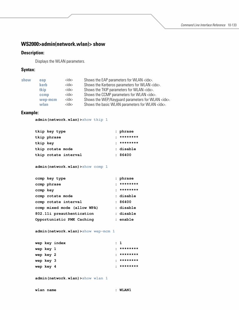
Command Line Interface Reference 10-133
WS2000>admin(network.wlan)> show
Description:
Displays the WLAN parameters.
Syntax:
Example:admin(network.wlan)>show tkip 1
tkip key type : phrase
tkip phrase : ********
tkip key : ********
tkip rotate mode : disable
tkip rotate interval : 86400
admin(network.wlan)>show ccmp 1
ccmp key type : phrase
ccmp phrase : ********
ccmp key : ********
ccmp rotate mode : disable
ccmp rotate interval : 86400
ccmp mixed mode (allow WPA) : disable
802.11i preauthentication : disable
Opportunistic PMK Caching : enable
admin(network.wlan)>show wep-mcm 1
wep key index : 1
wep key 1 : ********
wep key 2 : ********
wep key 3 : ********
wep key 4 : ********
admin(network.wlan)>show wlan 1
wlan name : WLAN1
show eap <idx> Shows the EAP parameters for WLAN <idx>.kerb <idx> Shows the Kerberos parameters for WLAN <idx>.tkip <idx> Shows the TKIP parameters for WLAN <idx>.ccmp <idx> Shows the CCMP parameters for WLAN <idx>.wep-mcm <idx> Shows the WEP/Keyguard parameters for WLAN <idx>.wlan <idx> Shows the basic WLAN parameters for WLAN <idx>.
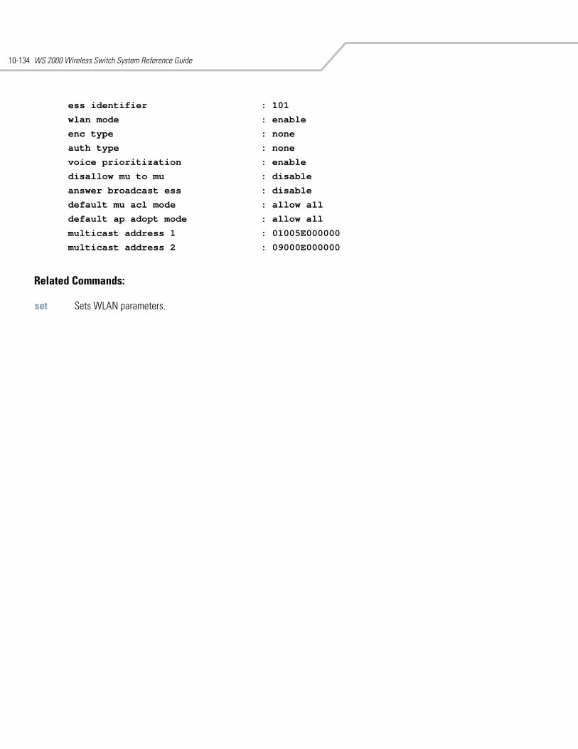
WS 2000 Wireless Switch System Reference Guide10-134
ess identifier : 101
wlan mode : enable
enc type : none
auth type : none
voice prioritization : enable
disallow mu to mu : disable
answer broadcast ess : disable
default mu acl mode : allow all
default ap adopt mode : allow all
multicast address 1 : 01005E000000
multicast address 2 : 09000E000000
Related Commands:
set Sets WLAN parameters.
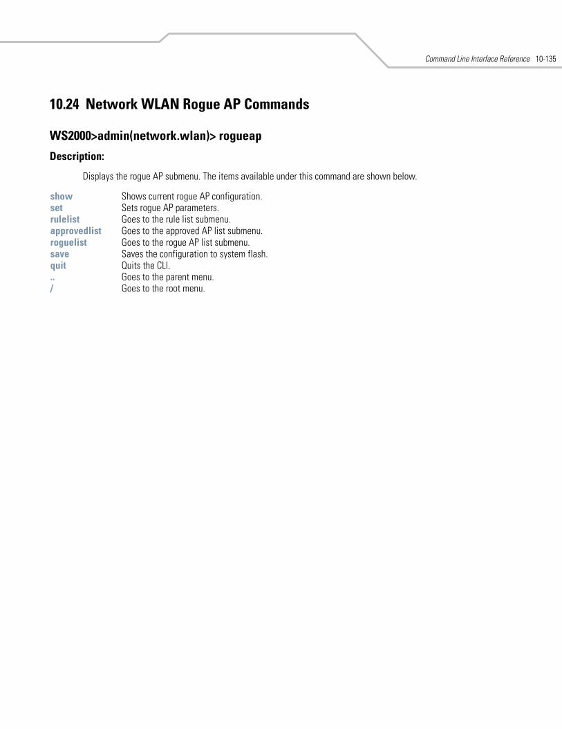
Command Line Interface Reference 10-135
10.24 Network WLAN Rogue AP Commands
WS2000>admin(network.wlan)> rogueap
Description:
Displays the rogue AP submenu. The items available under this command are shown below.
show Shows current rogue AP configuration.set Sets rogue AP parameters.rulelist Goes to the rule list submenu.approvedlist Goes to the approved AP list submenu.roguelist Goes to the rogue AP list submenu.save Saves the configuration to system flash.quit Quits the CLI. .. Goes to the parent menu./ Goes to the root menu.
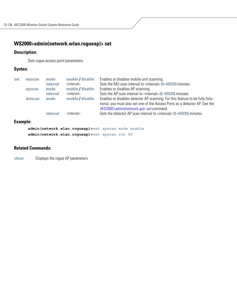
WS 2000 Wireless Switch System Reference Guide10-136
WS2000>admin(network.wlan.rogueap)> set
Description:
Sets rogue access point parameters.
Syntax:
Example: admin(network.wlan.rogueap)>set apscan mode enable
admin(network.wlan.rogueap)>set apscan int 60
Related Commands:
set muscan mode enable / disable Enables or disables mobile unit scanning.interval <interval> Sets the MU scan interval to <interval> (5–65535) minutes.
apscan mode enable / disable Enables or disables AP scanning.interval <interval> Sets the AP scan interval to <interval> (5–65535) minutes.
detscan mode enable / disable Enables or disables detector AP scanning. For this feature to be fully func-tional, you must also set one of the Access Ports as a detector AP. See the WS2000>admin(network.ap)> set command.
interval <interval> Sets the detector AP scan interval to <interval> (5–65535) minutes.
show Displays the rogue AP parameters.
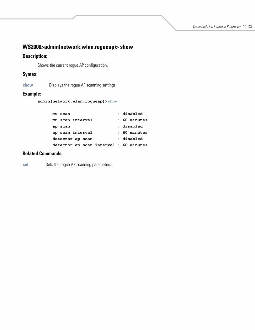
Command Line Interface Reference 10-137
WS2000>admin(network.wlan.rogueap)> show
Description:
Shows the current rogue AP configuration.
Syntax:
Example: admin(network.wlan.rogueap)>show
mu scan : disabled
mu scan interval : 60 minutes
ap scan : disabled
ap scan interval : 60 minutes
detector ap scan : disabled
detector ap scan interval : 60 minutes
Related Commands:
show Displays the rogue AP scanning settings.
set Sets the rogue AP scanning parameters.
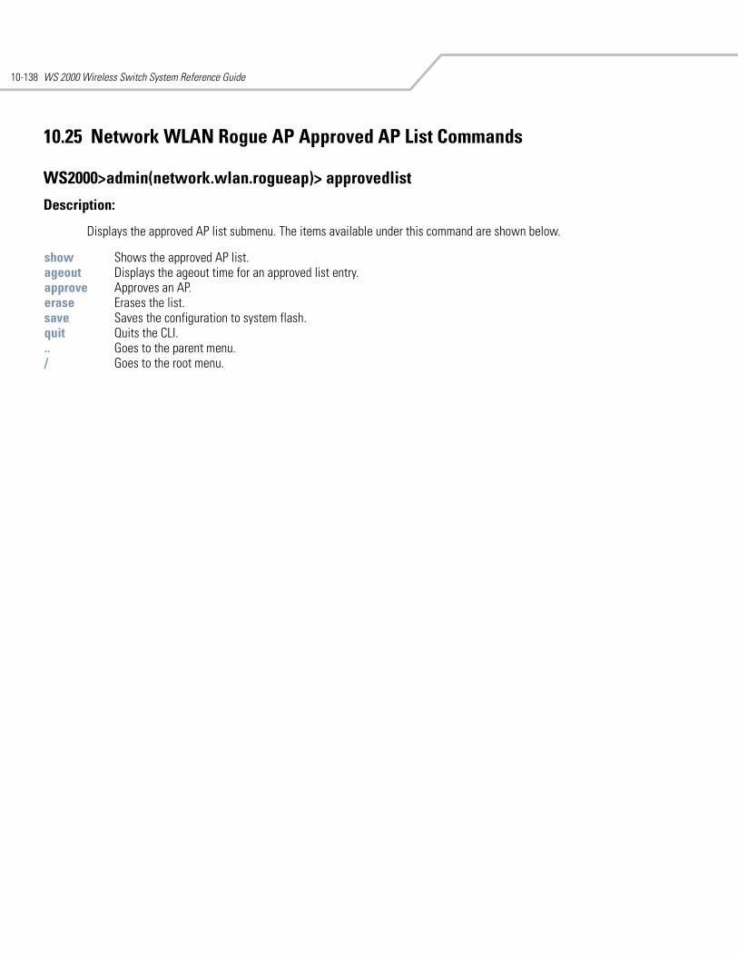
WS 2000 Wireless Switch System Reference Guide10-138
10.25 Network WLAN Rogue AP Approved AP List Commands
WS2000>admin(network.wlan.rogueap)> approvedlist
Description:
Displays the approved AP list submenu. The items available under this command are shown below.
show Shows the approved AP list.ageout Displays the ageout time for an approved list entry.approve Approves an AP.erase Erases the list. save Saves the configuration to system flash.quit Quits the CLI. .. Goes to the parent menu./ Goes to the root menu.
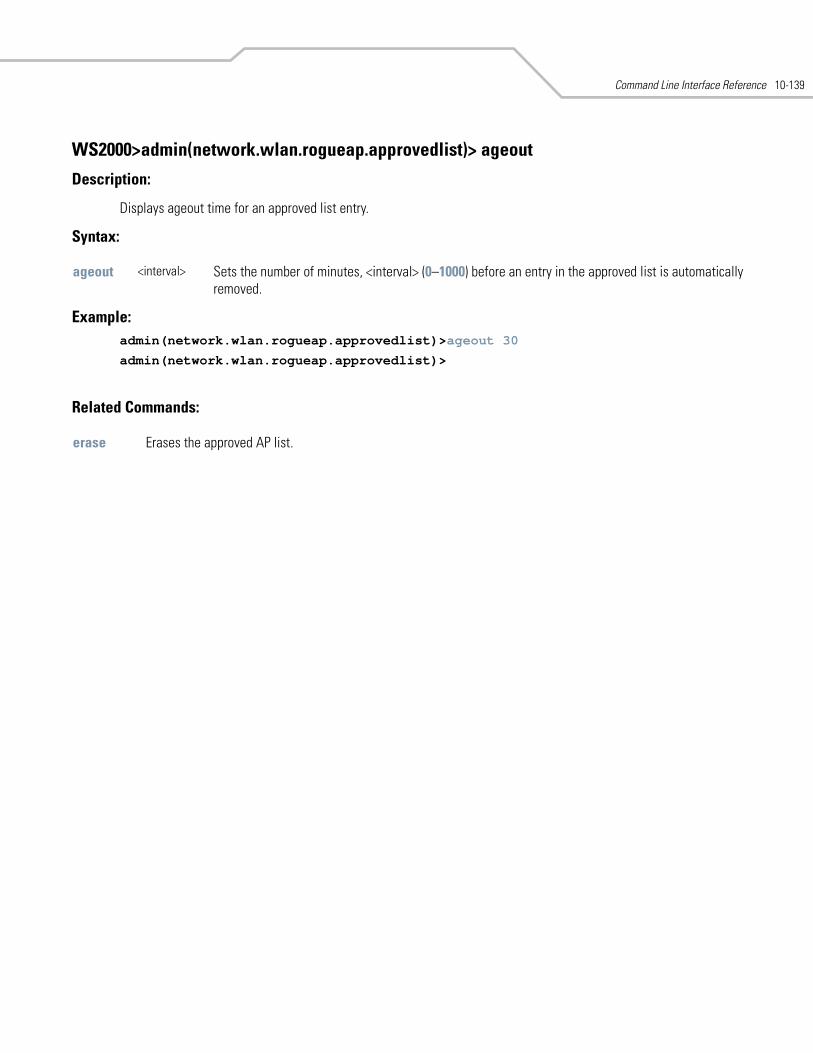
Command Line Interface Reference 10-139
WS2000>admin(network.wlan.rogueap.approvedlist)> ageout
Description:
Displays ageout time for an approved list entry.
Syntax:
Example: admin(network.wlan.rogueap.approvedlist)>ageout 30
admin(network.wlan.rogueap.approvedlist)>
Related Commands:
ageout <interval> Sets the number of minutes, <interval> (0–1000) before an entry in the approved list is automatically removed.
erase Erases the approved AP list.
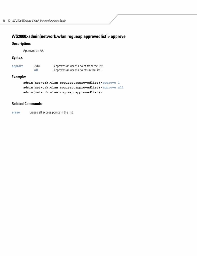
WS 2000 Wireless Switch System Reference Guide10-140
WS2000>admin(network.wlan.rogueap.approvedlist)> approve
Description:
Approves an AP.
Syntax:
Example: admin(network.wlan.rogueap.approvedlist)>approve 1
admin(network.wlan.rogueap.approvedlist)>approve all
admin(network.wlan.rogueap.approvedlist)>
Related Commands:
approve <idx> Approves an access point from the list.all Approves all access points in the list.
erase Erases all access points in the list.
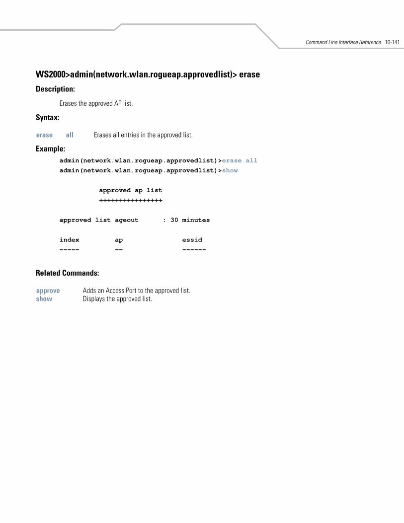
Command Line Interface Reference 10-141
WS2000>admin(network.wlan.rogueap.approvedlist)> erase
Description:
Erases the approved AP list.
Syntax:
Example: admin(network.wlan.rogueap.approvedlist)>erase all
admin(network.wlan.rogueap.approvedlist)>show
approved ap list
++++++++++++++++
approved list ageout : 30 minutes
index ap essid
----- -- ------
Related Commands:
erase all Erases all entries in the approved list.
approve Adds an Access Port to the approved list.show Displays the approved list.
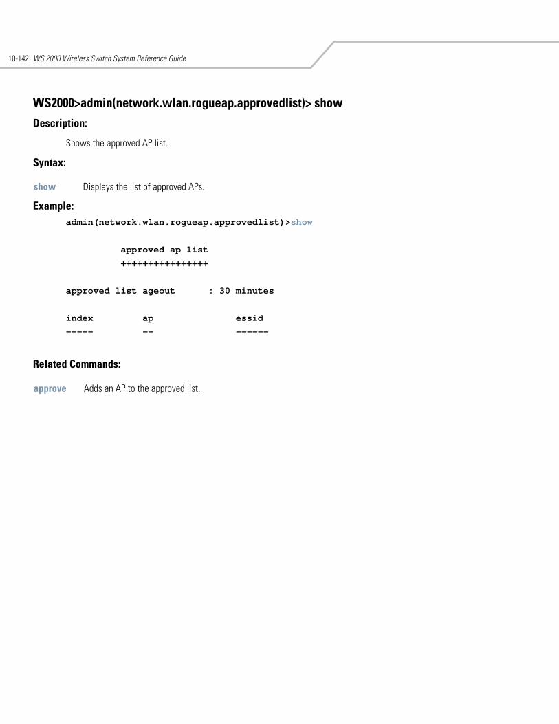
WS 2000 Wireless Switch System Reference Guide10-142
WS2000>admin(network.wlan.rogueap.approvedlist)> show
Description:
Shows the approved AP list.
Syntax:
Example: admin(network.wlan.rogueap.approvedlist)>show
approved ap list
++++++++++++++++
approved list ageout : 30 minutes
index ap essid
----- -- ------
Related Commands:
show Displays the list of approved APs.
approve Adds an AP to the approved list.
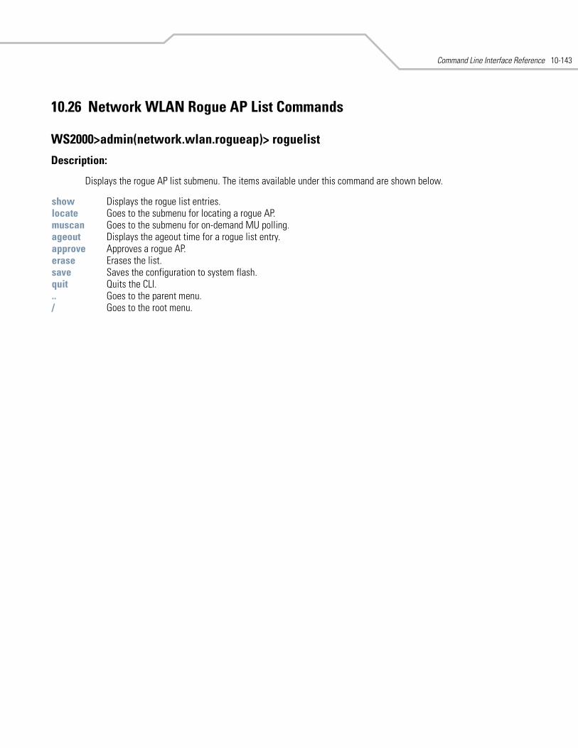
Command Line Interface Reference 10-143
10.26 Network WLAN Rogue AP List Commands
WS2000>admin(network.wlan.rogueap)> roguelist
Description:
Displays the rogue AP list submenu. The items available under this command are shown below.
show Displays the rogue list entries.locate Goes to the submenu for locating a rogue AP.muscan Goes to the submenu for on-demand MU polling.ageout Displays the ageout time for a rogue list entry. approve Approves a rogue AP.erase Erases the list. save Saves the configuration to system flash.quit Quits the CLI. .. Goes to the parent menu./ Goes to the root menu.
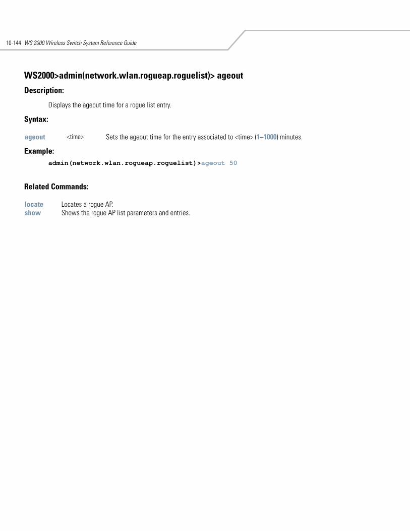
WS 2000 Wireless Switch System Reference Guide10-144
WS2000>admin(network.wlan.rogueap.roguelist)> ageout
Description:
Displays the ageout time for a rogue list entry.
Syntax:
Example: admin(network.wlan.rogueap.roguelist)>ageout 50
Related Commands:
ageout <time> Sets the ageout time for the entry associated to <time> (1–1000) minutes.
locate Locates a rogue AP.show Shows the rogue AP list parameters and entries.
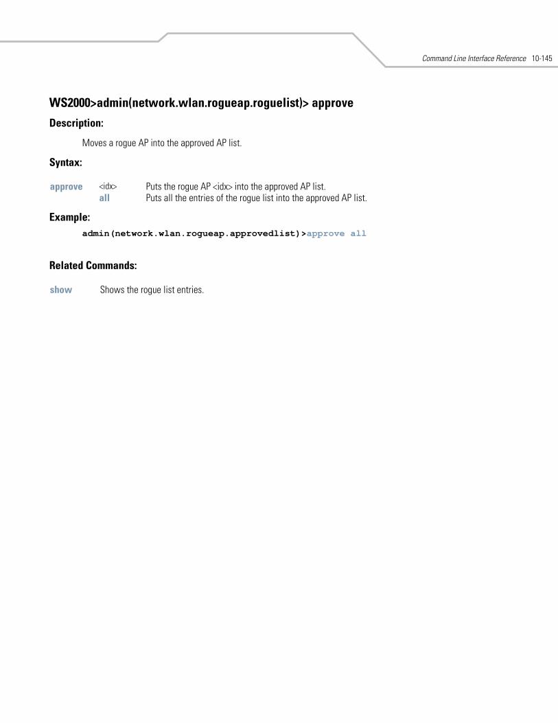
Command Line Interface Reference 10-145
WS2000>admin(network.wlan.rogueap.roguelist)> approve
Description:
Moves a rogue AP into the approved AP list.
Syntax:
Example: admin(network.wlan.rogueap.approvedlist)>approve all
Related Commands:
approve <idx> Puts the rogue AP <idx> into the approved AP list.all Puts all the entries of the rogue list into the approved AP list.
show Shows the rogue list entries.
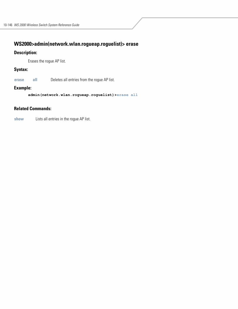
WS 2000 Wireless Switch System Reference Guide10-146
WS2000>admin(network.wlan.rogueap.roguelist)> erase
Description:
Erases the rogue AP list.
Syntax:
Example: admin(network.wlan.rogueap.roguelist)>erase all
Related Commands:
erase all Deletes all entries from the rogue AP list.
show Lists all entries in the rogue AP list.
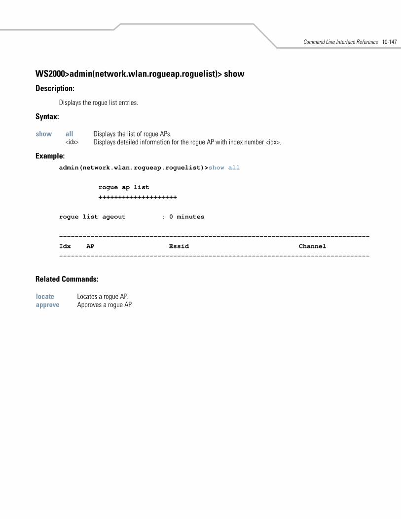
Command Line Interface Reference 10-147
WS2000>admin(network.wlan.rogueap.roguelist)> show
Description:
Displays the rogue list entries.
Syntax:
Example: admin(network.wlan.rogueap.roguelist)>show all
rogue ap list
++++++++++++++++++++
rogue list ageout : 0 minutes
-------------------------------------------------------------------------------
Idx AP Essid Channel
-------------------------------------------------------------------------------
Related Commands:
show all Displays the list of rogue APs.<idx> Displays detailed information for the rogue AP with index number <idx>.
locate Locates a rogue AP.approve Approves a rogue AP
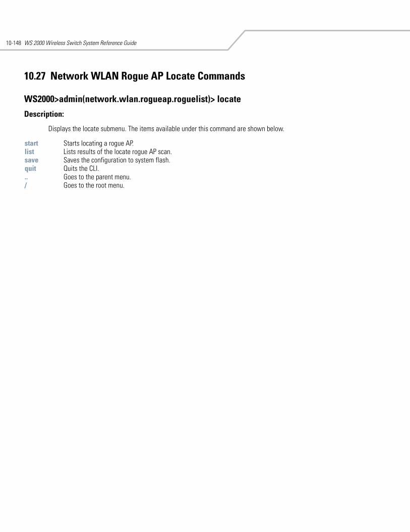
WS 2000 Wireless Switch System Reference Guide10-148
10.27 Network WLAN Rogue AP Locate Commands
WS2000>admin(network.wlan.rogueap.roguelist)> locate
Description:
Displays the locate submenu. The items available under this command are shown below.
start Starts locating a rogue AP.list Lists results of the locate rogue AP scan.save Saves the configuration to system flash.quit Quits the CLI. .. Goes to the parent menu./ Goes to the root menu.
Command Line Interface Reference 10-149
WS2000>admin(network.wlan.rogueap.roguelist.locate)> list
Description:
Lists the results of the locate rogue AP scan.
Syntax:
Example: admin(network.wlan.rogueap.roguelist.locate)>list
Related Commands:
list Lists the results of the locate rogue AP scan.
start Starts the rogue AP location process.
WS 2000 Wireless Switch System Reference Guide10-150
WS2000>admin(network.wlan.rogueap.roguelist.locate)> start
Description:
Locates a rogue AP.
Syntax:
Example: admin(network.wlan.rogueap.roguelist.locate)>start 00A0f8fe2344 wlan-engg
Related Commands:
start <mac> <essid> Starts locating a rogue AP where <mac> is the MAC address (or BSSID) of the rogue AP, and <essid> is the ESSID for the rogue AP.
list Lists information for the rogue AP found during the scan.
Command Line Interface Reference 10-151
10.28 Network WLAN Rogue AP MU Scan Commands
WS2000>admin(network.wlan.rogueap.roguelist)> muscan
Description:
Displays the MU scan submenu. The items available under this command are shown below.
start Starts a rogue AP scan using on-demand MU polling.list Lists the rogue APs found during the scan.save Saves the configuration to system flash.quit Quits the CLI. .. Goes to the parent menu./ Goes to the root menu.
WS 2000 Wireless Switch System Reference Guide10-152
WS2000>admin(network.wlan.rogueap.roguelist.muscan)> list
Description:
Lists the results of the locate rogue AP scan.
Syntax:
Example: admin(network.wlan.rogueap.roguelist.muscan)>list
Related Commands:
list Lists the results of the locate rogue AP scan.
start Starts the MU scan process.
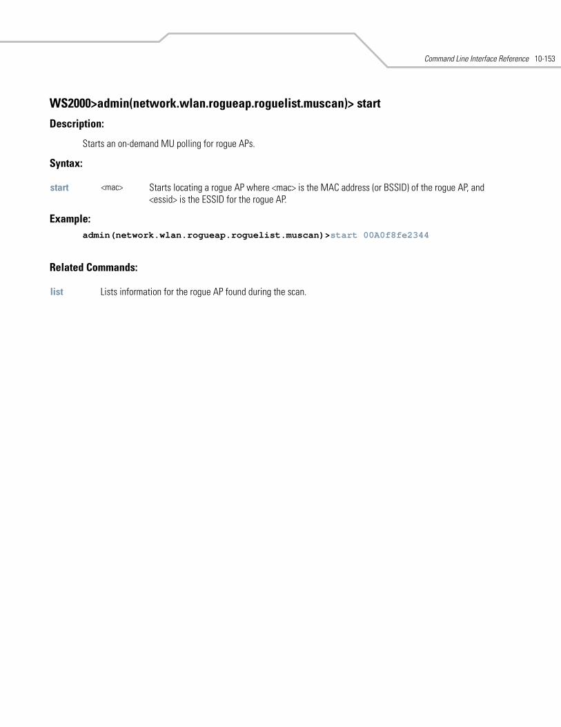
Command Line Interface Reference 10-153
WS2000>admin(network.wlan.rogueap.roguelist.muscan)> start
Description:
Starts an on-demand MU polling for rogue APs.
Syntax:
Example: admin(network.wlan.rogueap.roguelist.muscan)>start 00A0f8fe2344
Related Commands:
start <mac> Starts locating a rogue AP where <mac> is the MAC address (or BSSID) of the rogue AP, and <essid> is the ESSID for the rogue AP.
list Lists information for the rogue AP found during the scan.
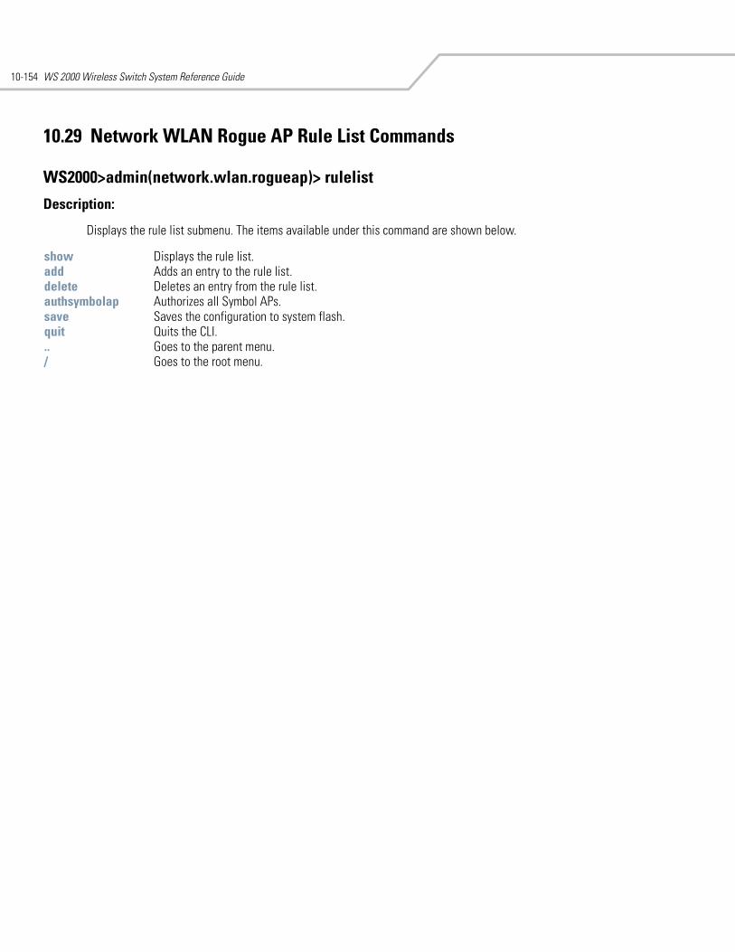
WS 2000 Wireless Switch System Reference Guide10-154
10.29 Network WLAN Rogue AP Rule List Commands
WS2000>admin(network.wlan.rogueap)> rulelist
Description:
Displays the rule list submenu. The items available under this command are shown below.
show Displays the rule list. add Adds an entry to the rule list.delete Deletes an entry from the rule list.authsymbolap Authorizes all Symbol APs.save Saves the configuration to system flash.quit Quits the CLI. .. Goes to the parent menu./ Goes to the root menu.
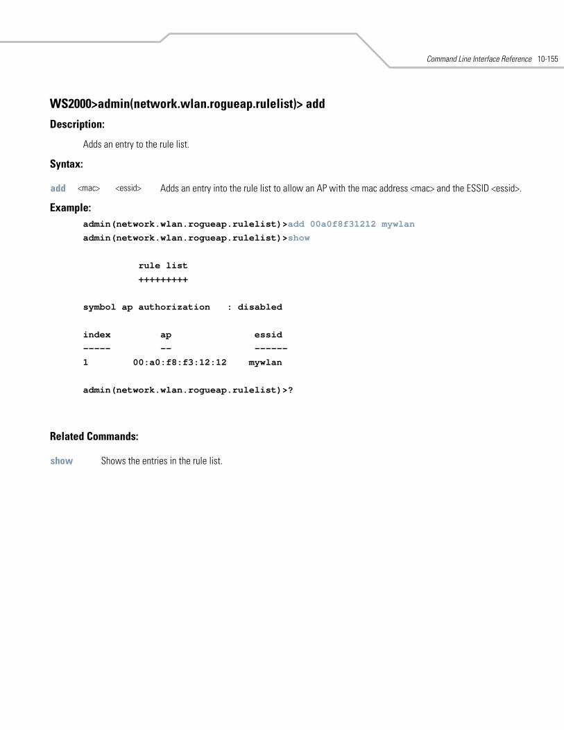
Command Line Interface Reference 10-155
WS2000>admin(network.wlan.rogueap.rulelist)> add
Description:
Adds an entry to the rule list.
Syntax:
Example: admin(network.wlan.rogueap.rulelist)>add 00a0f8f31212 mywlan
admin(network.wlan.rogueap.rulelist)>show
rule list
+++++++++
symbol ap authorization : disabled
index ap essid
----- -- ------
1 00:a0:f8:f3:12:12 mywlan
admin(network.wlan.rogueap.rulelist)>?
Related Commands:
add <mac> <essid> Adds an entry into the rule list to allow an AP with the mac address <mac> and the ESSID <essid>.
show Shows the entries in the rule list.
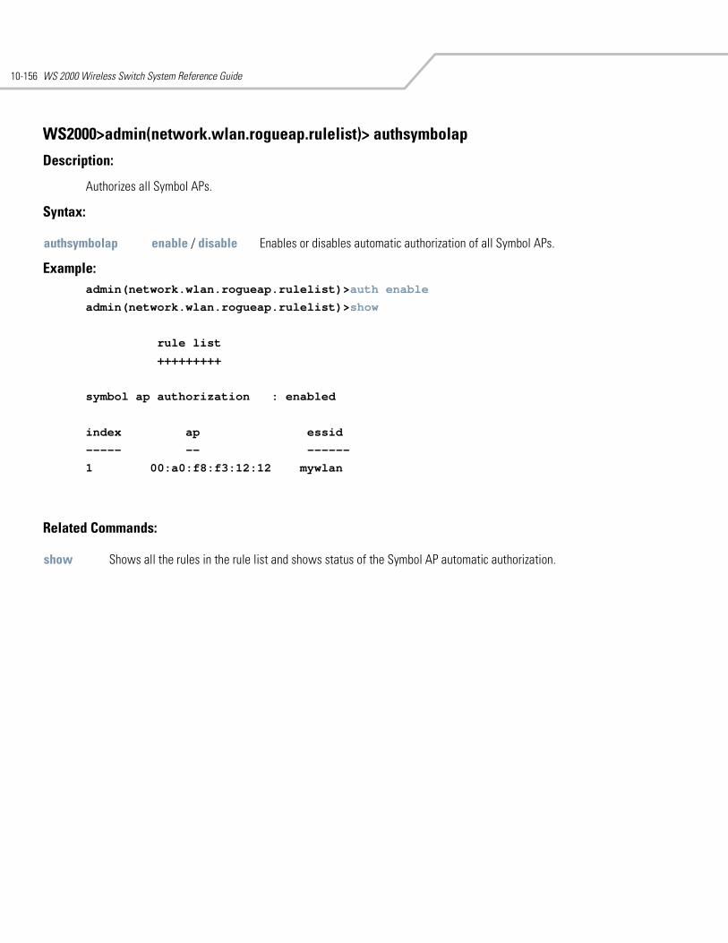
WS 2000 Wireless Switch System Reference Guide10-156
WS2000>admin(network.wlan.rogueap.rulelist)> authsymbolap
Description:
Authorizes all Symbol APs.
Syntax:
Example: admin(network.wlan.rogueap.rulelist)>auth enable
admin(network.wlan.rogueap.rulelist)>show
rule list
+++++++++
symbol ap authorization : enabled
index ap essid
----- -- ------
1 00:a0:f8:f3:12:12 mywlan
Related Commands:
authsymbolap enable / disable Enables or disables automatic authorization of all Symbol APs.
show Shows all the rules in the rule list and shows status of the Symbol AP automatic authorization.
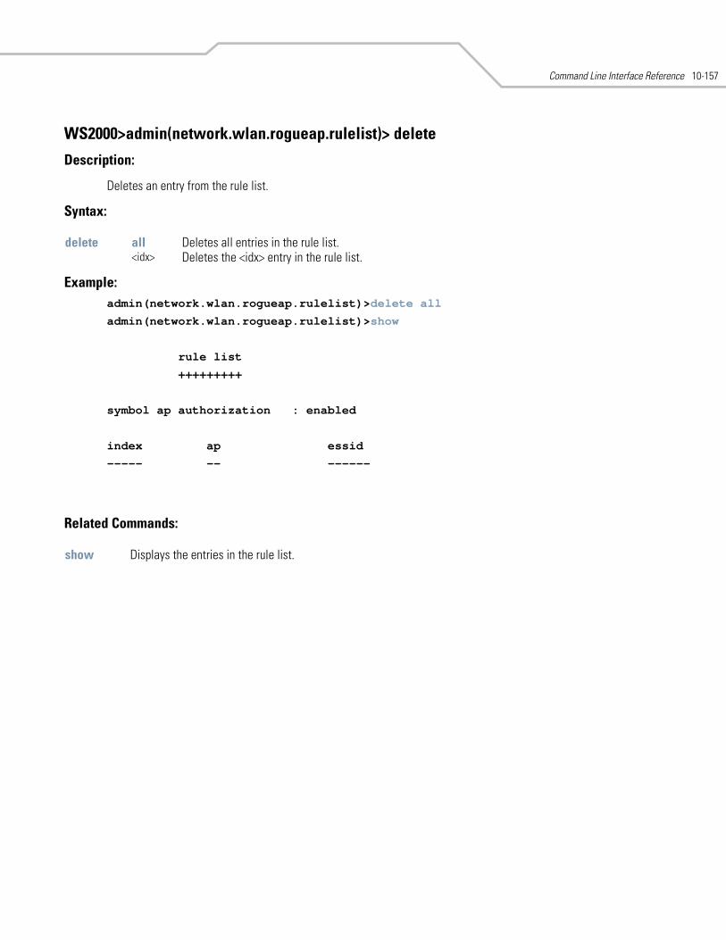
Command Line Interface Reference 10-157
WS2000>admin(network.wlan.rogueap.rulelist)> delete
Description:
Deletes an entry from the rule list.
Syntax:
Example: admin(network.wlan.rogueap.rulelist)>delete all
admin(network.wlan.rogueap.rulelist)>show
rule list
+++++++++
symbol ap authorization : enabled
index ap essid
----- -- ------
Related Commands:
delete all Deletes all entries in the rule list.<idx> Deletes the <idx> entry in the rule list.
show Displays the entries in the rule list.
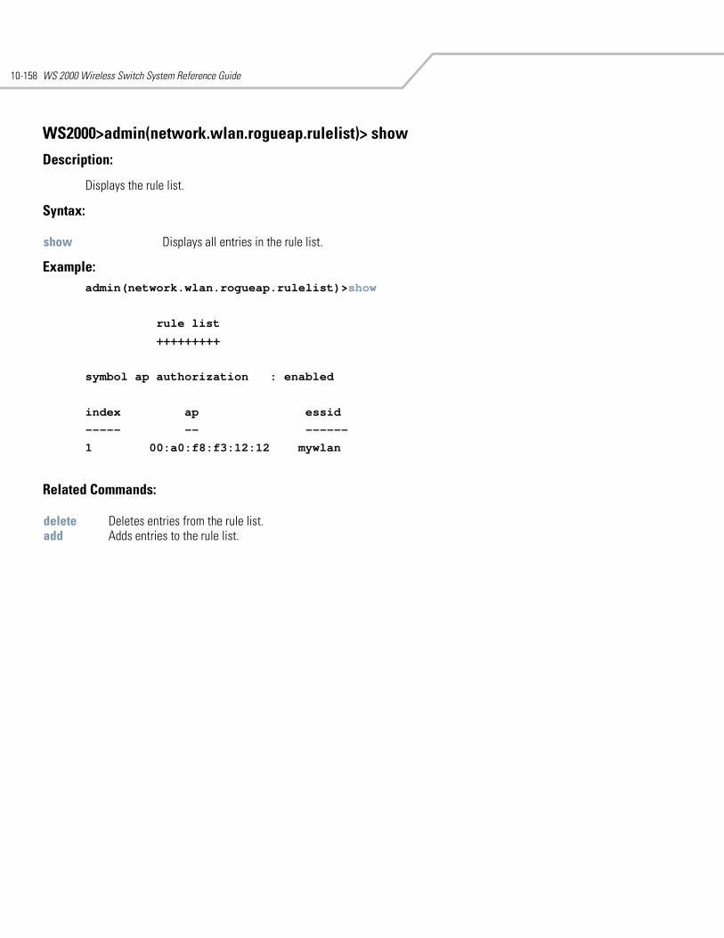
WS 2000 Wireless Switch System Reference Guide10-158
WS2000>admin(network.wlan.rogueap.rulelist)> show
Description:
Displays the rule list.
Syntax:
Example: admin(network.wlan.rogueap.rulelist)>show
rule list
+++++++++
symbol ap authorization : enabled
index ap essid
----- -- ------
1 00:a0:f8:f3:12:12 mywlan
Related Commands:
show Displays all entries in the rule list.
delete Deletes entries from the rule list.add Adds entries to the rule list.
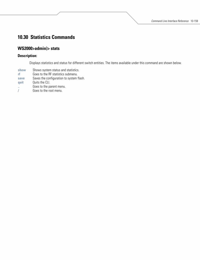
Command Line Interface Reference 10-159
10.30 Statistics Commands
WS2000>admin)> stats
Description:
Displays statistics and status for different switch entities. The items available under this command are shown below.
show Shows system status and statistics.rf Goes to the RF statistics submenu.save Saves the configuration to system flash.quit Quits the CLI. .. Goes to the parent menu./ Goes to the root menu.
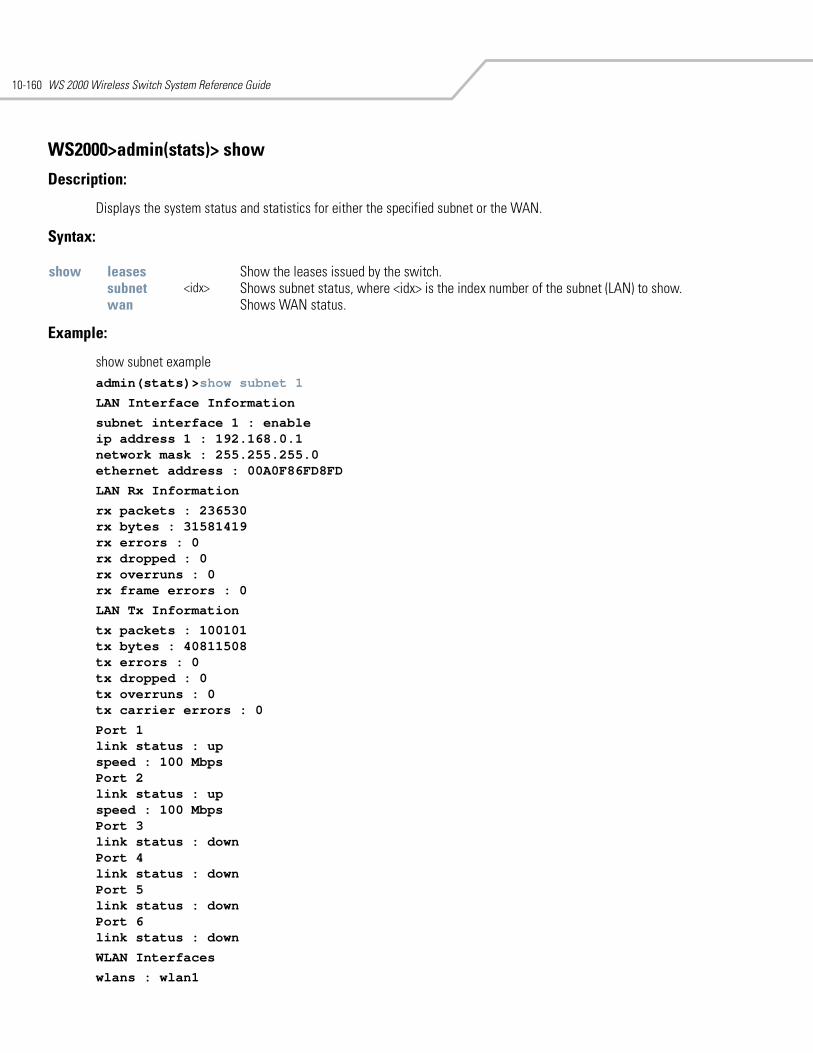
WS 2000 Wireless Switch System Reference Guide10-160
WS2000>admin(stats)> show
Description:
Displays the system status and statistics for either the specified subnet or the WAN.
Syntax:
Example:
show subnet example admin(stats)>show subnet 1
LAN Interface Information
subnet interface 1 : enableip address 1 : 192.168.0.1network mask : 255.255.255.0ethernet address : 00A0F86FD8FD
LAN Rx Information
rx packets : 236530rx bytes : 31581419rx errors : 0rx dropped : 0rx overruns : 0rx frame errors : 0
LAN Tx Information
tx packets : 100101tx bytes : 40811508tx errors : 0tx dropped : 0tx overruns : 0tx carrier errors : 0
Port 1link status : upspeed : 100 MbpsPort 2link status : upspeed : 100 MbpsPort 3link status : downPort 4link status : downPort 5link status : downPort 6link status : down
WLAN Interfaces
wlans : wlan1
show leases Show the leases issued by the switch.subnet <idx> Shows subnet status, where <idx> is the index number of the subnet (LAN) to show. wan Shows WAN status.
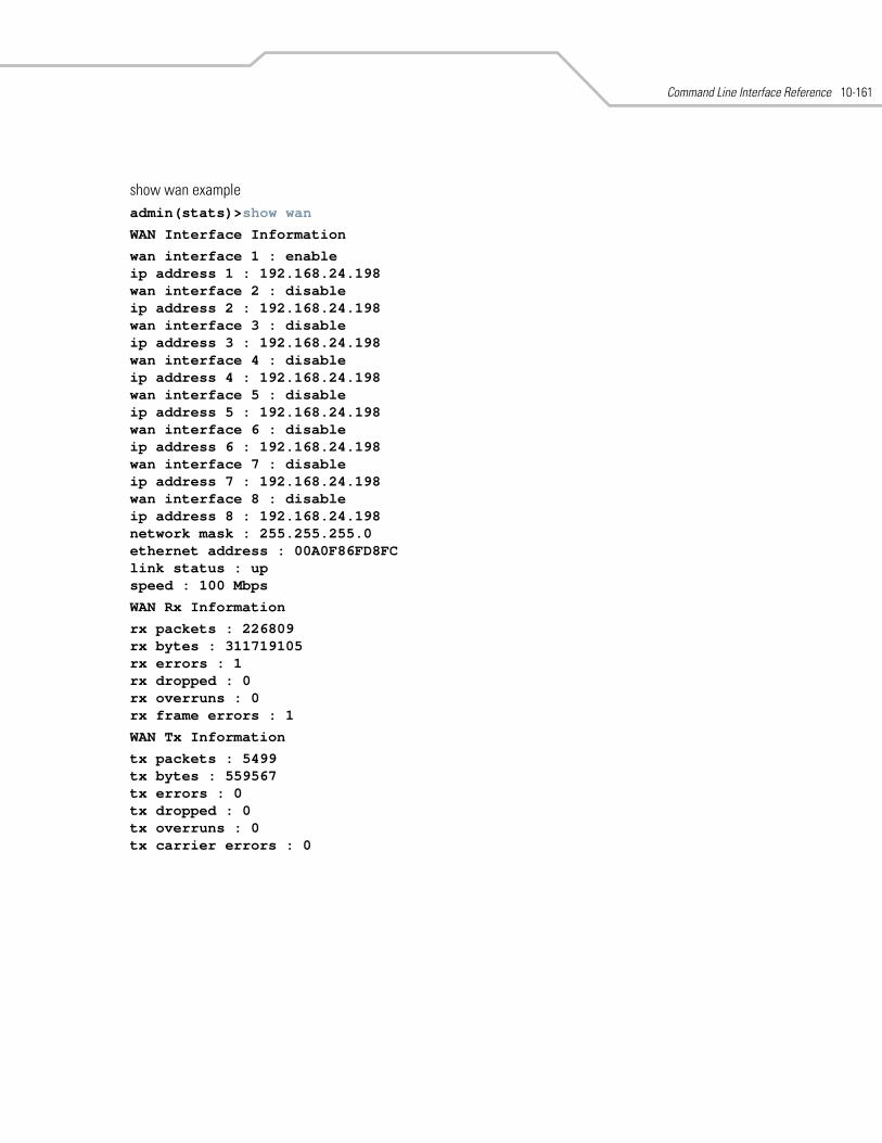
Command Line Interface Reference 10-161
show wan example admin(stats)>show wan
WAN Interface Information
wan interface 1 : enableip address 1 : 192.168.24.198wan interface 2 : disableip address 2 : 192.168.24.198wan interface 3 : disableip address 3 : 192.168.24.198wan interface 4 : disableip address 4 : 192.168.24.198wan interface 5 : disableip address 5 : 192.168.24.198wan interface 6 : disableip address 6 : 192.168.24.198wan interface 7 : disableip address 7 : 192.168.24.198wan interface 8 : disableip address 8 : 192.168.24.198network mask : 255.255.255.0ethernet address : 00A0F86FD8FClink status : upspeed : 100 Mbps
WAN Rx Information
rx packets : 226809rx bytes : 311719105rx errors : 1rx dropped : 0rx overruns : 0rx frame errors : 1
WAN Tx Information
tx packets : 5499tx bytes : 559567tx errors : 0tx dropped : 0tx overruns : 0tx carrier errors : 0
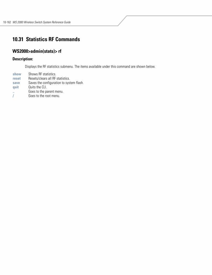
WS 2000 Wireless Switch System Reference Guide10-162
10.31 Statistics RF Commands
WS2000>admin(stats)> rf
Description:
Displays the RF statistics submenu. The items available under this command are shown below.
show Shows RF statistics.reset Resets/clears all RF statistics.save Saves the configuration to system flash.quit Quits the CLI. .. Goes to the parent menu./ Goes to the root menu.
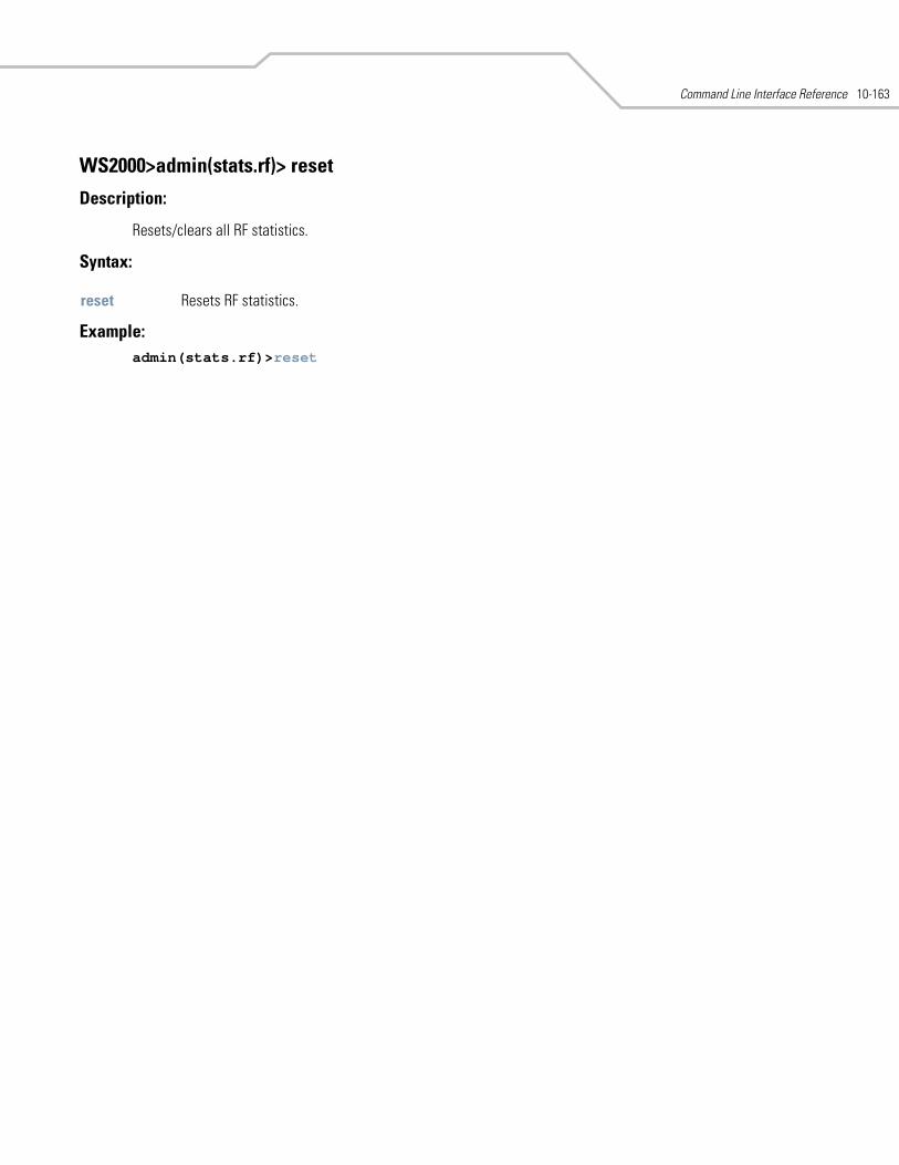
Command Line Interface Reference 10-163
WS2000>admin(stats.rf)> reset
Description:
Resets/clears all RF statistics.
Syntax:
Example:admin(stats.rf)>reset
reset Resets RF statistics.
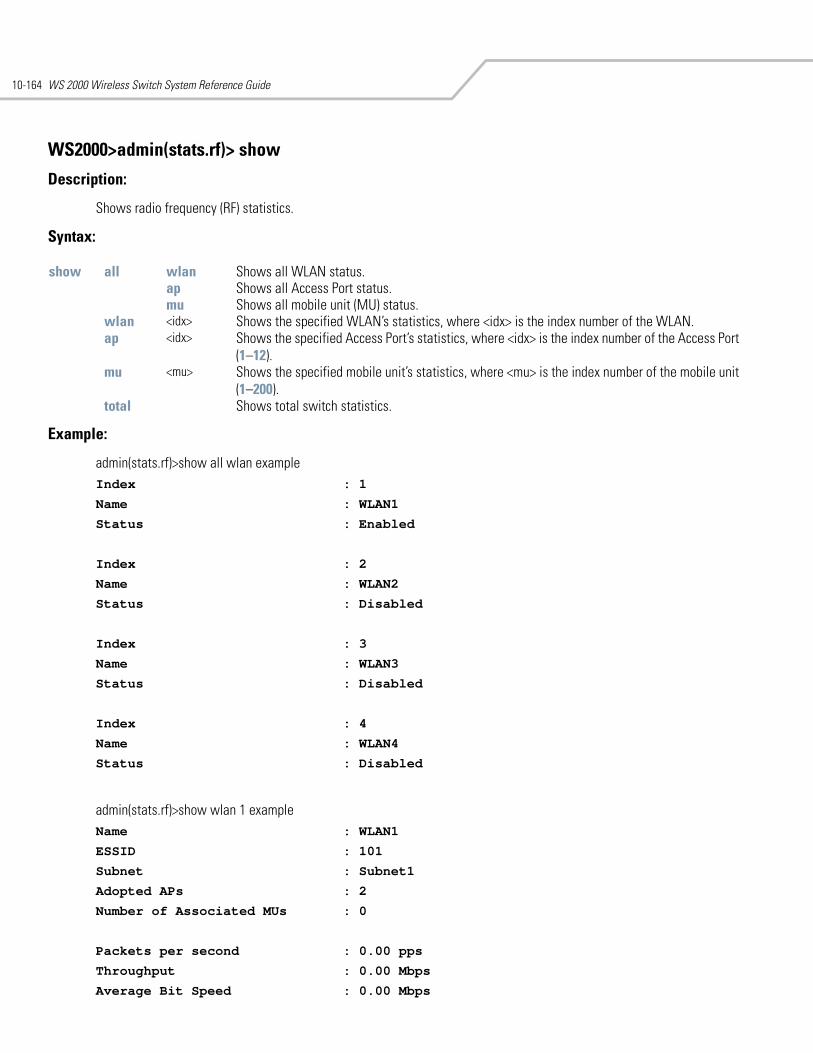
WS 2000 Wireless Switch System Reference Guide10-164
WS2000>admin(stats.rf)> show
Description:
Shows radio frequency (RF) statistics.
Syntax:
Example:
admin(stats.rf)>show all wlan example Index : 1
Name : WLAN1
Status : Enabled
Index : 2
Name : WLAN2
Status : Disabled
Index : 3
Name : WLAN3
Status : Disabled
Index : 4
Name : WLAN4
Status : Disabled
admin(stats.rf)>show wlan 1 exampleName : WLAN1
ESSID : 101
Subnet : Subnet1
Adopted APs : 2
Number of Associated MUs : 0
Packets per second : 0.00 pps
Throughput : 0.00 Mbps
Average Bit Speed : 0.00 Mbps
show all wlan Shows all WLAN status.ap Shows all Access Port status.mu Shows all mobile unit (MU) status.
wlan <idx> Shows the specified WLAN’s statistics, where <idx> is the index number of the WLAN. ap <idx> Shows the specified Access Port’s statistics, where <idx> is the index number of the Access Port
(1–12). mu <mu> Shows the specified mobile unit’s statistics, where <mu> is the index number of the mobile unit
(1–200).total Shows total switch statistics.
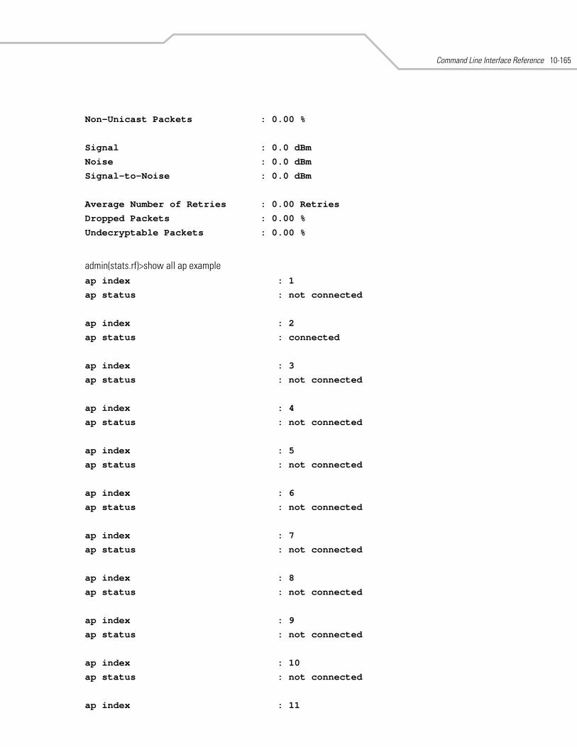
Command Line Interface Reference 10-165
Non-Unicast Packets : 0.00 %
Signal : 0.0 dBm
Noise : 0.0 dBm
Signal-to-Noise : 0.0 dBm
Average Number of Retries : 0.00 Retries
Dropped Packets : 0.00 %
Undecryptable Packets : 0.00 %
admin(stats.rf)>show all ap exampleap index : 1
ap status : not connected
ap index : 2
ap status : connected
ap index : 3
ap status : not connected
ap index : 4
ap status : not connected
ap index : 5
ap status : not connected
ap index : 6
ap status : not connected
ap index : 7
ap status : not connected
ap index : 8
ap status : not connected
ap index : 9
ap status : not connected
ap index : 10
ap status : not connected
ap index : 11
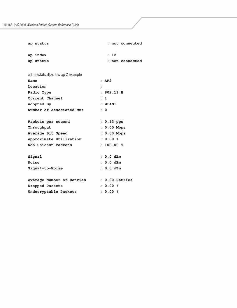
WS 2000 Wireless Switch System Reference Guide10-166
ap status : not connected
ap index : 12
ap status : not connected
admin(stats.rf)>show ap 2 exampleName : AP2
Location :
Radio Type : 802.11 B
Current Channel : 1
Adopted By : WLAN1
Number of Associated Mus : 0
Packets per second : 0.13 pps
Throughput : 0.00 Mbps
Average Bit Speed : 0.00 Mbps
Approximate Utilization : 0.00 %
Non-Unicast Packets : 100.00 %
Signal : 0.0 dBm
Noise : 0.0 dBm
Signal-to-Noise : 0.0 dBm
Average Number of Retries : 0.00 Retries
Dropped Packets : 0.00 %
Undecryptable Packets : 0.00 %
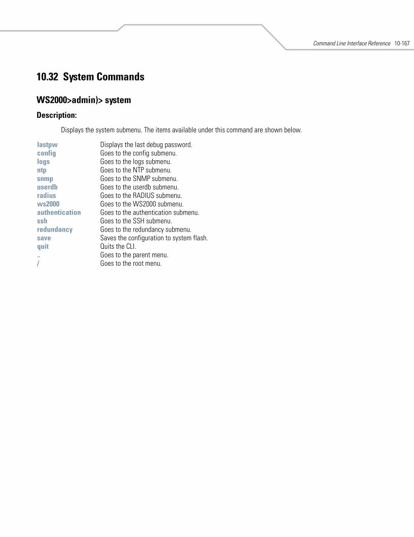
Command Line Interface Reference 10-167
10.32 System Commands
WS2000>admin)> system
Description:
Displays the system submenu. The items available under this command are shown below.
lastpw Displays the last debug password. config Goes to the config submenu. logs Goes to the logs submenu. ntp Goes to the NTP submenu. snmp Goes to the SNMP submenu. userdb Goes to the userdb submenu. radius Goes to the RADIUS submenu. ws2000 Goes to the WS2000 submenu.authentication Goes to the authentication submenu. ssh Goes to the SSH submenu. redundancy Goes to the redundancy submenu. save Saves the configuration to system flash.quit Quits the CLI. .. Goes to the parent menu./ Goes to the root menu.
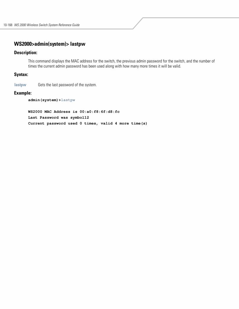
WS 2000 Wireless Switch System Reference Guide10-168
WS2000>admin(system)> lastpw
Description:
This command displays the MAC address for the switch, the previous admin password for the switch, and the number of times the current admin password has been used along with how many more times it will be valid.
Syntax:
Example: admin(system)>lastpw
WS2000 MAC Address is 00:a0:f8:6f:d8:fc
Last Password was symbol12
Current password used 0 times, valid 4 more time(s)
lastpw Gets the last password of the system.
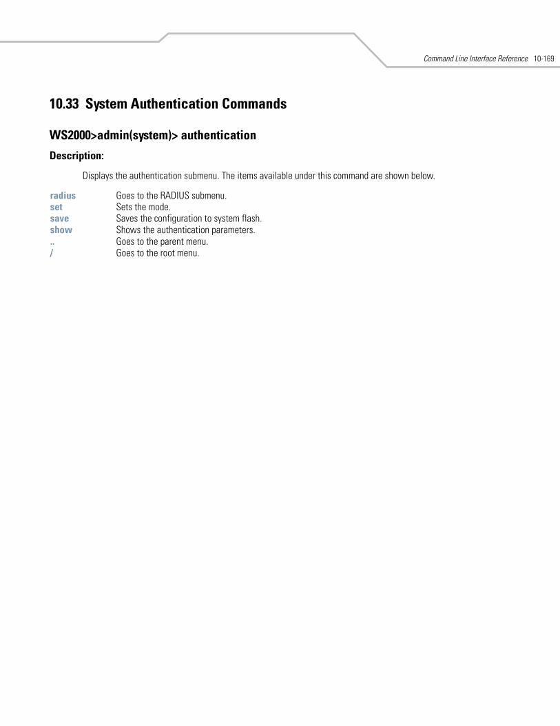
Command Line Interface Reference 10-169
10.33 System Authentication Commands
WS2000>admin(system)> authentication
Description:
Displays the authentication submenu. The items available under this command are shown below.
radius Goes to the RADIUS submenu. set Sets the mode. save Saves the configuration to system flash.show Shows the authentication parameters... Goes to the parent menu./ Goes to the root menu.
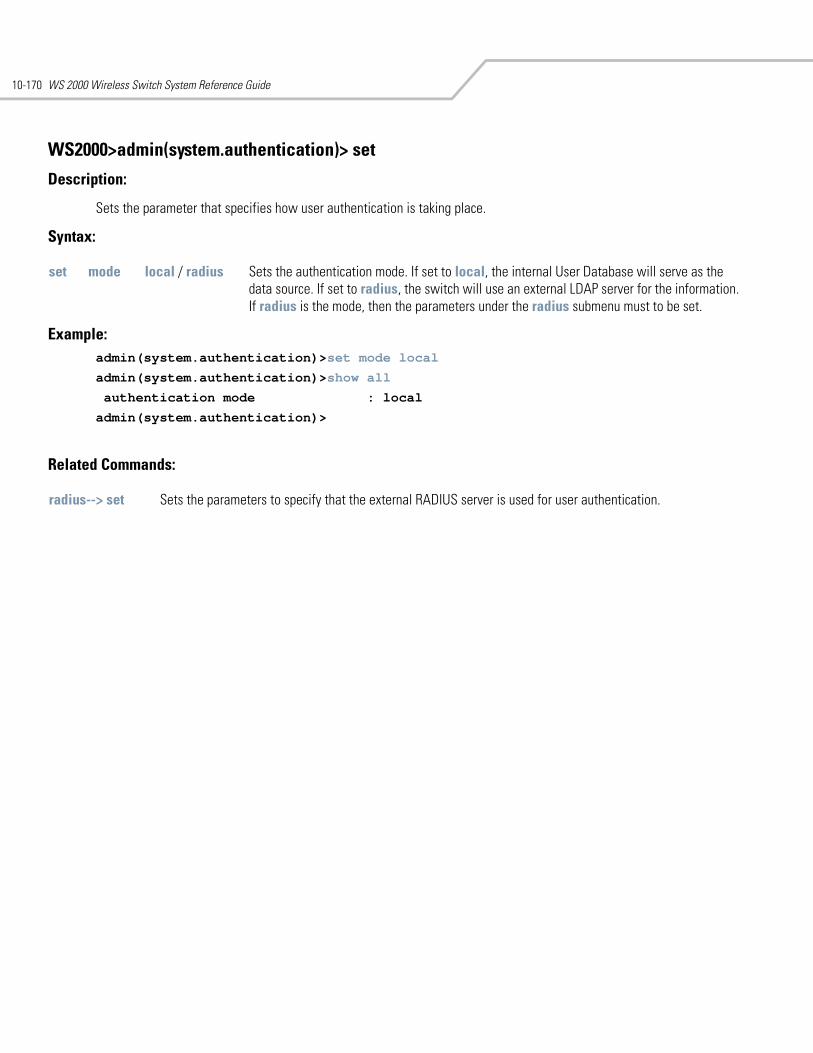
WS 2000 Wireless Switch System Reference Guide10-170
WS2000>admin(system.authentication)> set
Description:
Sets the parameter that specifies how user authentication is taking place.
Syntax:
Example: admin(system.authentication)>set mode local
admin(system.authentication)>show all
authentication mode : local
admin(system.authentication)>
Related Commands:
set mode local / radius Sets the authentication mode. If set to local, the internal User Database will serve as the data source. If set to radius, the switch will use an external LDAP server for the information. If radius is the mode, then the parameters under the radius submenu must to be set.
radius--> set Sets the parameters to specify that the external RADIUS server is used for user authentication.
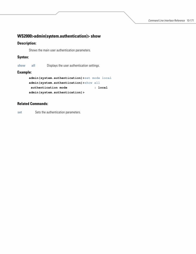
Command Line Interface Reference 10-171
WS2000>admin(system.authentication)> show
Description:
Shows the main user authentication parameters.
Syntax:
Example: admin(system.authentication)>set mode local
admin(system.authentication)>show all
authentication mode : local
admin(system.authentication)>
Related Commands:
show all Displays the user authentication settings.
set Sets the authentication parameters.
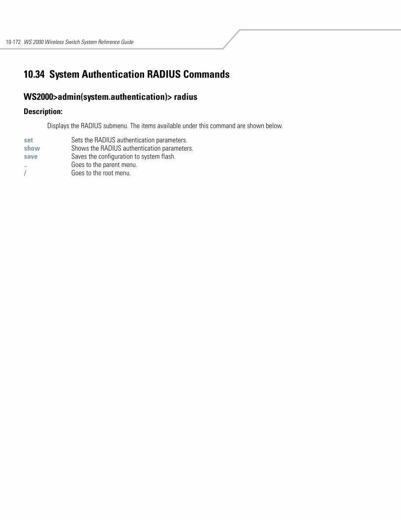
WS 2000 Wireless Switch System Reference Guide10-172
10.34 System Authentication RADIUS Commands
WS2000>admin(system.authentication)> radius
Description:
Displays the RADIUS submenu. The items available under this command are shown below.
set Sets the RADIUS authentication parameters.show Shows the RADIUS authentication parameters.save Saves the configuration to system flash... Goes to the parent menu./ Goes to the root menu.
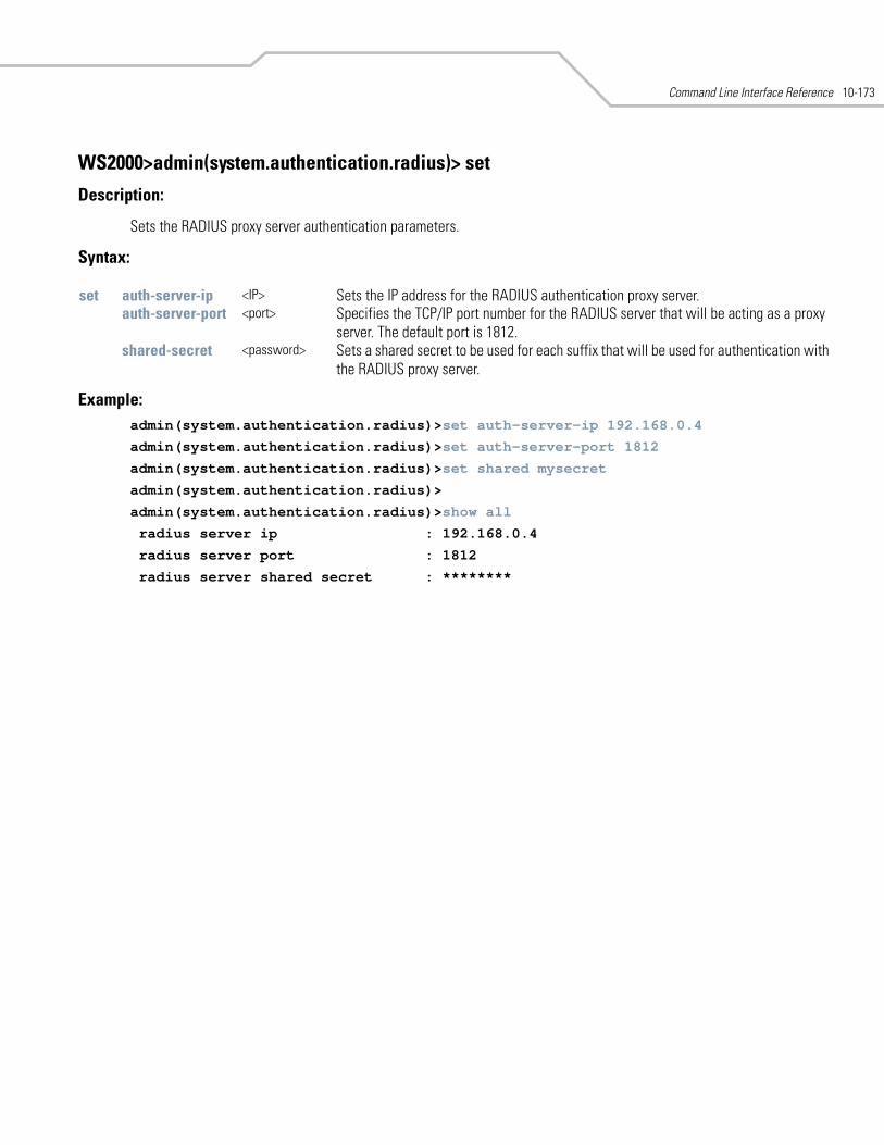
Command Line Interface Reference 10-173
WS2000>admin(system.authentication.radius)> set
Description:
Sets the RADIUS proxy server authentication parameters.
Syntax:
Example: admin(system.authentication.radius)>set auth-server-ip 192.168.0.4
admin(system.authentication.radius)>set auth-server-port 1812
admin(system.authentication.radius)>set shared mysecret
admin(system.authentication.radius)>
admin(system.authentication.radius)>show all
radius server ip : 192.168.0.4
radius server port : 1812
radius server shared secret : ********
set auth-server-ip <IP> Sets the IP address for the RADIUS authentication proxy server.auth-server-port <port> Specifies the TCP/IP port number for the RADIUS server that will be acting as a proxy
server. The default port is 1812.shared-secret <password> Sets a shared secret to be used for each suffix that will be used for authentication with
the RADIUS proxy server.
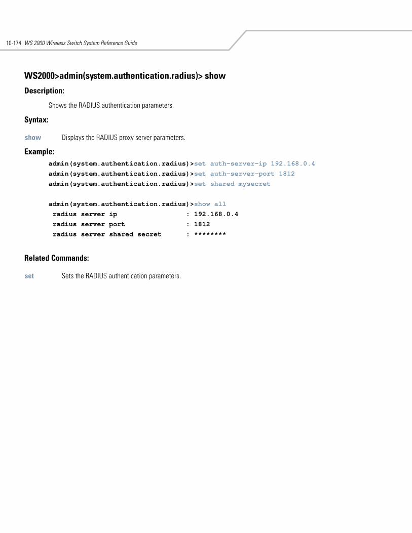
WS 2000 Wireless Switch System Reference Guide10-174
WS2000>admin(system.authentication.radius)> show
Description:
Shows the RADIUS authentication parameters.
Syntax:
Example: admin(system.authentication.radius)>set auth-server-ip 192.168.0.4
admin(system.authentication.radius)>set auth-server-port 1812
admin(system.authentication.radius)>set shared mysecret
admin(system.authentication.radius)>show all
radius server ip : 192.168.0.4
radius server port : 1812
radius server shared secret : ********
Related Commands:
show Displays the RADIUS proxy server parameters.
set Sets the RADIUS authentication parameters.
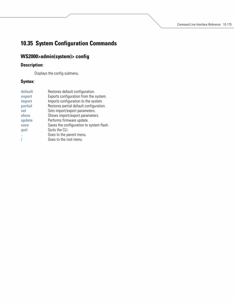
Command Line Interface Reference 10-175
10.35 System Configuration Commands
WS2000>admin(system)> config
Description:
Displays the config submenu.
Syntax:
default Restores default configuration.export Exports configuration from the system.import Imports configuration to the system.partial Restores partial default configuration. set Sets import/export parameters.show Shows import/export parameters.update Performs firmware update.save Saves the configuration to system flash.quit Quits the CLI. .. Goes to the parent menu./ Goes to the root menu.
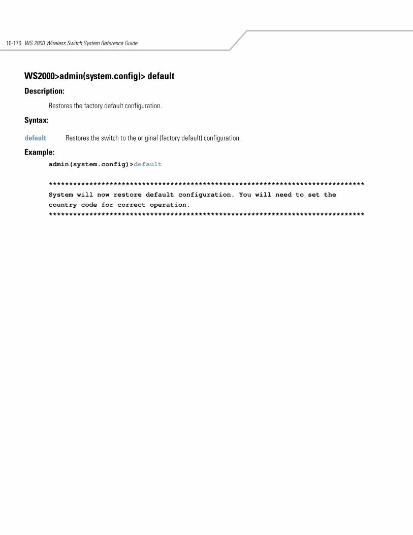
WS 2000 Wireless Switch System Reference Guide10-176
WS2000>admin(system.config)> default
Description:
Restores the factory default configuration.
Syntax:
Example:admin(system.config)>default
******************************************************************************
System will now restore default configuration. You will need to set the
country code for correct operation.
******************************************************************************
default Restores the switch to the original (factory default) configuration.
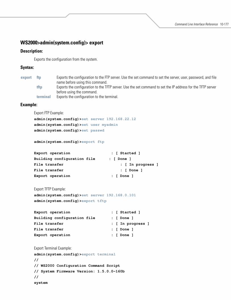
Command Line Interface Reference 10-177
WS2000>admin(system.config)> export
Description:
Exports the configuration from the system.
Syntax:
Example:
Export FTP Example: admin(system.config)>set server 192.168.22.12
admin(system.config)>set user myadmin
admin(system.config)>set passwd
admin(system.config)>export ftp
Export operation : [ Started ]
Building configuration file : [ Done ]
File transfer : [ In progress ]
File transfer : [ Done ]
Export operation : [ Done ]
Export TFTP Example: admin(system.config)>set server 192.168.0.101
admin(system.config)>export tftp
Export operation : [ Started ]
Building configuration file : [ Done ]
File transfer : [ In progress ]
File transfer : [ Done ]
Export operation : [ Done ]
Export Terminal Example:admin(system.config)>export terminal
//
// WS2000 Configuration Command Script
// System Firmware Version: 1.5.0.0-160b
//
system
export ftp Exports the configuration to the FTP server. Use the set command to set the server, user, password, and file name before using this command.
tftp Exports the configuration to the TFTP server. Use the set command to set the IP address for the TFTP server before using the command.
terminal Exports the configuration to the terminal.
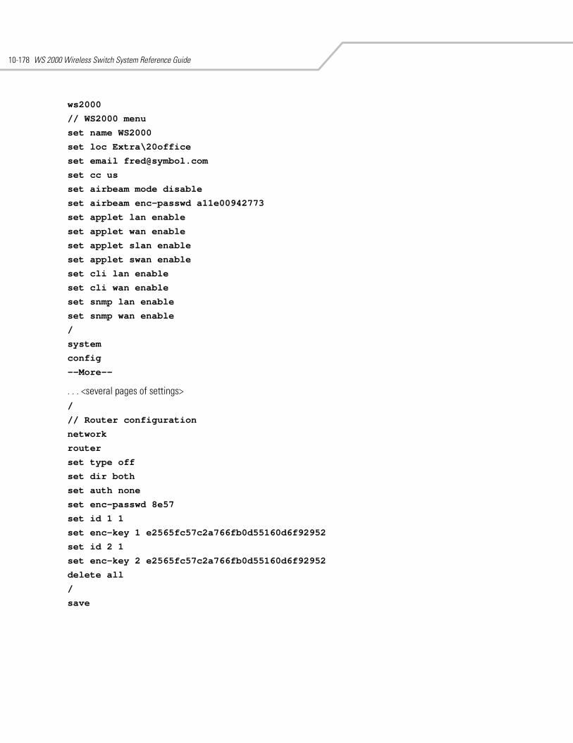
WS 2000 Wireless Switch System Reference Guide10-178
ws2000
// WS2000 menu
set name WS2000
set loc Extra\20office
set email [email protected]
set cc us
set airbeam mode disable
set airbeam enc-passwd a11e00942773
set applet lan enable
set applet wan enable
set applet slan enable
set applet swan enable
set cli lan enable
set cli wan enable
set snmp lan enable
set snmp wan enable
/
system
config
--More--
. . . <several pages of settings> /
// Router configuration
network
router
set type off
set dir both
set auth none
set enc-passwd 8e57
set id 1 1
set enc-key 1 e2565fc57c2a766fb0d55160d6f92952
set id 2 1
set enc-key 2 e2565fc57c2a766fb0d55160d6f92952
delete all
/
save
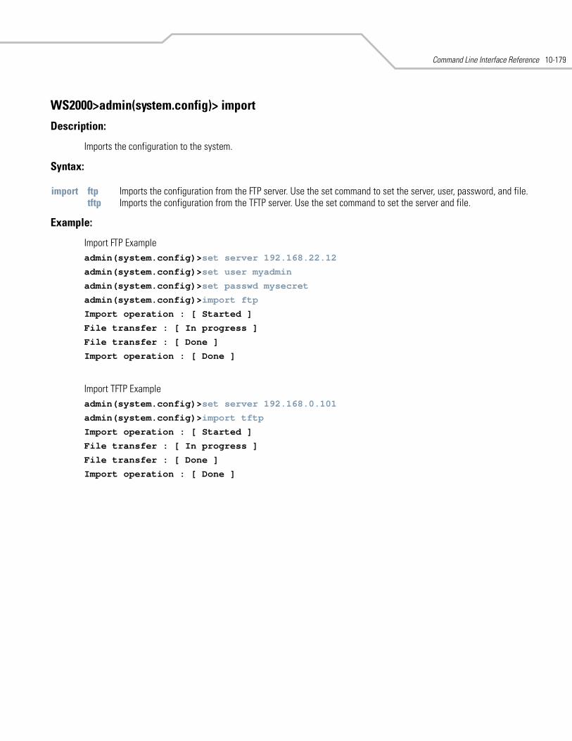
Command Line Interface Reference 10-179
WS2000>admin(system.config)> import
Description:
Imports the configuration to the system.
Syntax:
Example:
Import FTP Example admin(system.config)>set server 192.168.22.12
admin(system.config)>set user myadmin
admin(system.config)>set passwd mysecret
admin(system.config)>import ftp
Import operation : [ Started ]
File transfer : [ In progress ]
File transfer : [ Done ]
Import operation : [ Done ]
Import TFTP Example admin(system.config)>set server 192.168.0.101
admin(system.config)>import tftp
Import operation : [ Started ]
File transfer : [ In progress ]
File transfer : [ Done ]
Import operation : [ Done ]
import ftp Imports the configuration from the FTP server. Use the set command to set the server, user, password, and file.tftp Imports the configuration from the TFTP server. Use the set command to set the server and file.
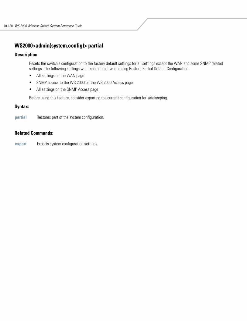
WS 2000 Wireless Switch System Reference Guide10-180
WS2000>admin(system.config)> partial
Description:
Resets the switch's configuration to the factory default settings for all settings except the WAN and some SNMP related settings. The following settings will remain intact when using Restore Partial Default Configuration:
• All settings on the WAN page
• SNMP access to the WS 2000 on the WS 2000 Access page
• All settings on the SNMP Access page
Before using this feature, consider exporting the current configuration for safekeeping.
Syntax:
Related Commands:
partial Restores part of the system configuration.
export Exports system configuration settings.
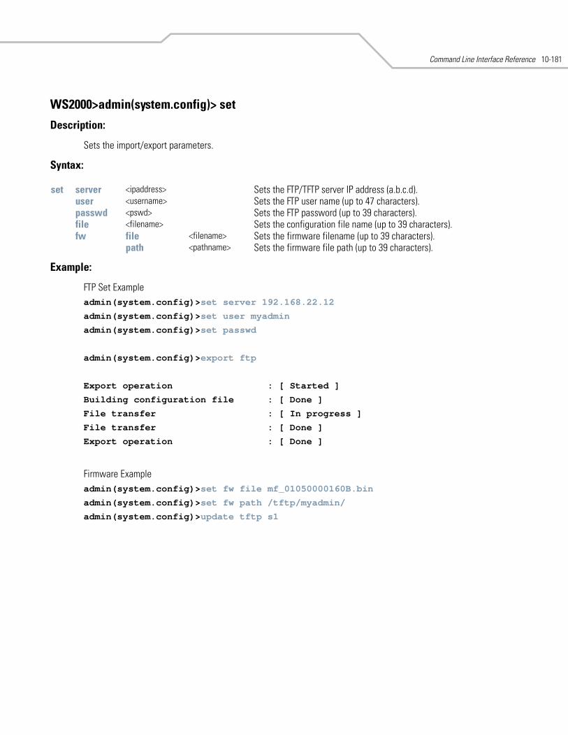
Command Line Interface Reference 10-181
WS2000>admin(system.config)> set
Description:
Sets the import/export parameters.
Syntax:
Example:
FTP Set Exampleadmin(system.config)>set server 192.168.22.12
admin(system.config)>set user myadmin
admin(system.config)>set passwd
admin(system.config)>export ftp
Export operation : [ Started ]
Building configuration file : [ Done ]
File transfer : [ In progress ]
File transfer : [ Done ]
Export operation : [ Done ]
Firmware Exampleadmin(system.config)>set fw file mf_01050000160B.bin
admin(system.config)>set fw path /tftp/myadmin/
admin(system.config)>update tftp s1
set server <ipaddress> Sets the FTP/TFTP server IP address (a.b.c.d).user <username> Sets the FTP user name (up to 47 characters).passwd <pswd> Sets the FTP password (up to 39 characters).file <filename> Sets the configuration file name (up to 39 characters).fw file <filename> Sets the firmware filename (up to 39 characters).
path <pathname> Sets the firmware file path (up to 39 characters).
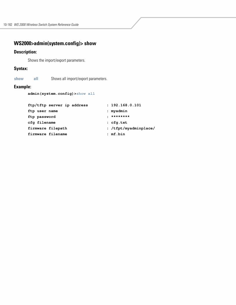
WS 2000 Wireless Switch System Reference Guide10-182
WS2000>admin(system.config)> show
Description:
Shows the import/export parameters.
Syntax:
Example: admin(system.config)>show all
ftp/tftp server ip address : 192.168.0.101
ftp user name : myadmin
ftp password : ********
cfg filename : cfg.txt
firmware filepath : /tfpt/myadminplace/
firmware filename : mf.bin
show all Shows all import/export parameters.
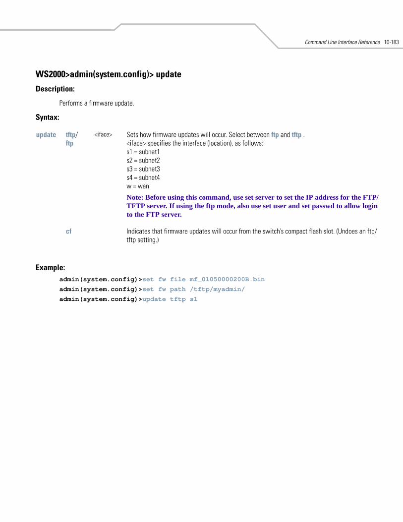
Command Line Interface Reference 10-183
WS2000>admin(system.config)> update
Description:
Performs a firmware update.
Syntax:
Example: admin(system.config)>set fw file mf_01050000200B.bin
admin(system.config)>set fw path /tftp/myadmin/
admin(system.config)>update tftp s1
update tftp/ftp
<iface> Sets how firmware updates will occur. Select between ftp and tftp . <iface> specifies the interface (location), as follows: s1 = subnet1 s2 = subnet2 s3 = subnet3 s4 = subnet4 w = wan
Note: Before using this command, use set server to set the IP address for the FTP/TFTP server. If using the ftp mode, also use set user and set passwd to allow login to the FTP server.
cf Indicates that firmware updates will occur from the switch’s compact flash slot. (Undoes an ftp/tftp setting.)
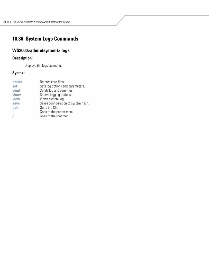
WS 2000 Wireless Switch System Reference Guide10-184
10.36 System Logs Commands
WS2000>admin(system)> logs
Description:
Displays the logs submenu.
Syntax:
delete Deletes core files.set Sets log options and parameters.send Sends log and core files.show Shows logging options.view Views system log. save Saves configuration to system flash.quit Quits the CLI. .. Goes to the parent menu./ Goes to the root menu.
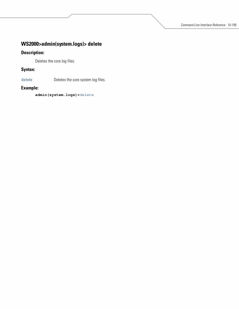
Command Line Interface Reference 10-185
WS2000>admin(system.logs)> delete
Description:
Deletes the core log files.
Syntax:
Example: admin(system.logs)>delete
delete Deletes the core system log files.
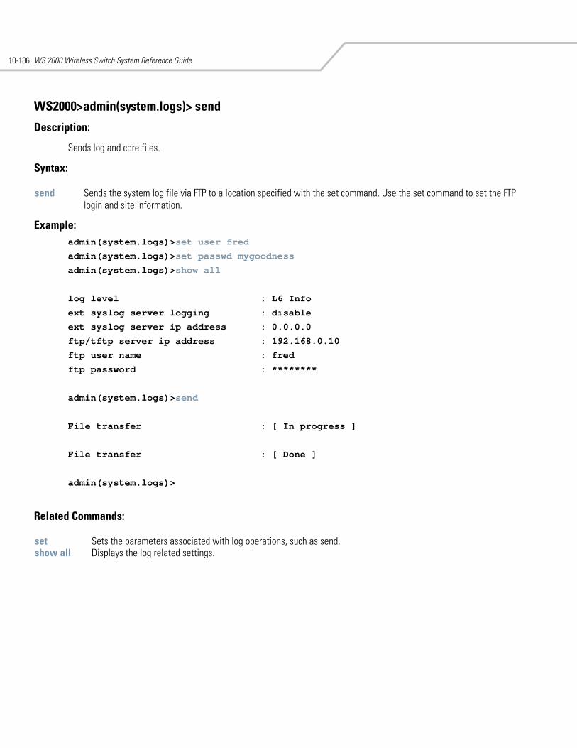
WS 2000 Wireless Switch System Reference Guide10-186
WS2000>admin(system.logs)> send
Description:
Sends log and core files.
Syntax:
Example: admin(system.logs)>set user fred
admin(system.logs)>set passwd mygoodness
admin(system.logs)>show all
log level : L6 Info
ext syslog server logging : disable
ext syslog server ip address : 0.0.0.0
ftp/tftp server ip address : 192.168.0.10
ftp user name : fred
ftp password : ********
admin(system.logs)>send
File transfer : [ In progress ]
File transfer : [ Done ]
admin(system.logs)>
Related Commands:
send Sends the system log file via FTP to a location specified with the set command. Use the set command to set the FTP login and site information.
set Sets the parameters associated with log operations, such as send. show all Displays the log related settings.
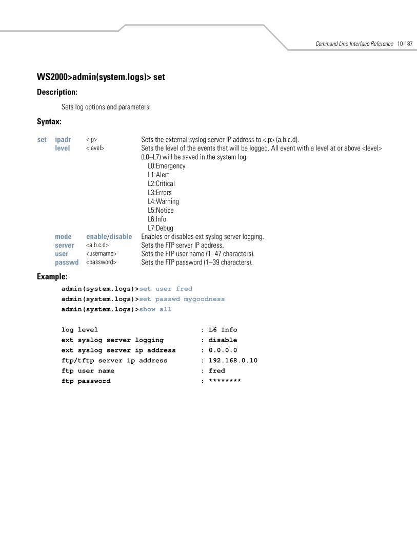
Command Line Interface Reference 10-187
WS2000>admin(system.logs)> set
Description:
Sets log options and parameters.
Syntax:
Example:admin(system.logs)>set user fred
admin(system.logs)>set passwd mygoodness
admin(system.logs)>show all
log level : L6 Info
ext syslog server logging : disable
ext syslog server ip address : 0.0.0.0
ftp/tftp server ip address : 192.168.0.10
ftp user name : fred
ftp password : ********
set ipadr <ip> Sets the external syslog server IP address to <ip> (a.b.c.d).level <level> Sets the level of the events that will be logged. All event with a level at or above <level>
(L0–L7) will be saved in the system log. L0:Emergency L1:Alert L2:Critical L3:Errors L4:Warning L5:Notice L6:Info L7:Debug
mode enable/disable Enables or disables ext syslog server logging.server <a.b.c.d> Sets the FTP server IP address.user <username> Sets the FTP user name (1–47 characters).passwd <password> Sets the FTP password (1–39 characters).
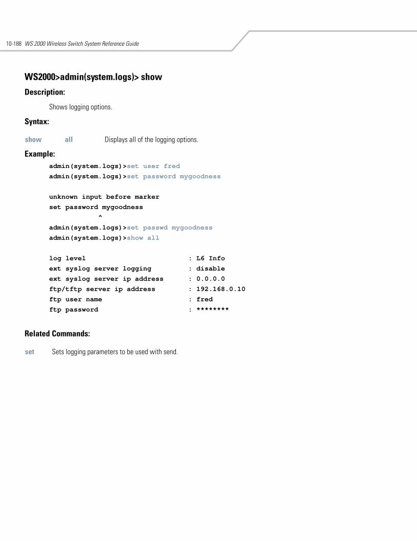
WS 2000 Wireless Switch System Reference Guide10-188
WS2000>admin(system.logs)> show
Description:
Shows logging options.
Syntax:
Example: admin(system.logs)>set user fred
admin(system.logs)>set password mygoodness
unknown input before marker
set password mygoodness
^
admin(system.logs)>set passwd mygoodness
admin(system.logs)>show all
log level : L6 Info
ext syslog server logging : disable
ext syslog server ip address : 0.0.0.0
ftp/tftp server ip address : 192.168.0.10
ftp user name : fred
ftp password : ********
Related Commands:
show all Displays all of the logging options.
set Sets logging parameters to be used with send.
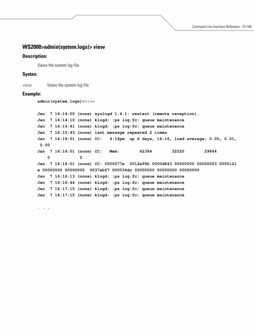
Command Line Interface Reference 10-189
WS2000>admin(system.logs)> view
Description:
Views the system log file.
Syntax:
Example: admin(system.logs)>view
Jan 7 16:14:00 (none) syslogd 1.4.1: restart (remote reception).
Jan 7 16:14:10 (none) klogd: :ps log:fc: queue maintenance
Jan 7 16:14:41 (none) klogd: :ps log:fc: queue maintenance
Jan 7 16:15:43 (none) last message repeated 2 times
Jan 7 16:16:01 (none) CC: 4:16pm up 6 days, 16:16, load average: 0.00, 0.01,
0.00
Jan 7 16:16:01 (none) CC: Mem: 62384 32520 29864
0 0
Jan 7 16:16:01 (none) CC: 0000077e 0012e95b 0000d843 00000000 00000003 0000121
e 00000000 00000000 0037ebf7 000034dc 00000000 00000000 00000000
Jan 7 16:16:13 (none) klogd: :ps log:fc: queue maintenance
Jan 7 16:16:44 (none) klogd: :ps log:fc: queue maintenance
Jan 7 16:17:15 (none) klogd: :ps log:fc: queue maintenance
Jan 7 16:17:15 (none) klogd: :ps log:fc: queue maintenance
. . .
view Views the system log file.
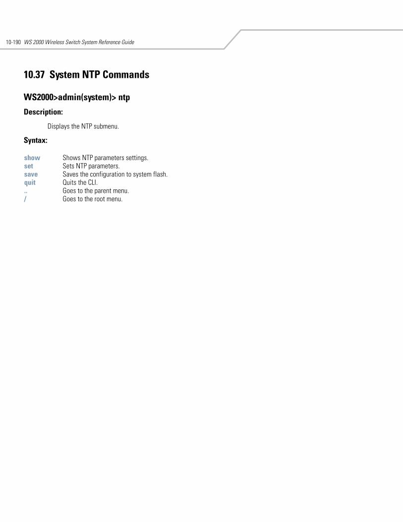
WS 2000 Wireless Switch System Reference Guide10-190
10.37 System NTP Commands
WS2000>admin(system)> ntp
Description:
Displays the NTP submenu.
Syntax:
show Shows NTP parameters settings. set Sets NTP parameters. save Saves the configuration to system flash.quit Quits the CLI. .. Goes to the parent menu./ Goes to the root menu.
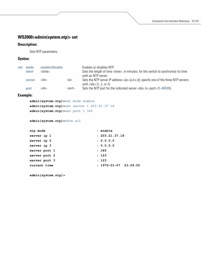
Command Line Interface Reference 10-191
WS2000>admin(system.ntp)> set
Description:
Sets NTP parameters.
Syntax:
Example: admin(system.ntp)>set mode enable
admin(system.ntp)>set server 1 203.21.37.18
admin(system.ntp)>set port 1 345
admin(system.ntp)>show all
ntp mode : enable
server ip 1 : 203.21.37.18
server ip 2 : 0.0.0.0
server ip 3 : 0.0.0.0
server port 1 : 345
server port 2 : 123
server port 3 : 123
current time : 1970-01-07 23:29:05
admin(system.ntp)>
set mode enable/disable Enables or disables NTP.intrvl <time> Sets the length of time <time>, in minutes, for the switch to synchronize its time
with an NTP server.server <idx> <ip> Sets the NTP server IP address <ip> (a.b.c.d); specify one of the three NTP servers
with <idx> (1, 2, or 3).port <idx> <port> Sets the NTP port for the indicated server <idx> to <port> (1–65535).
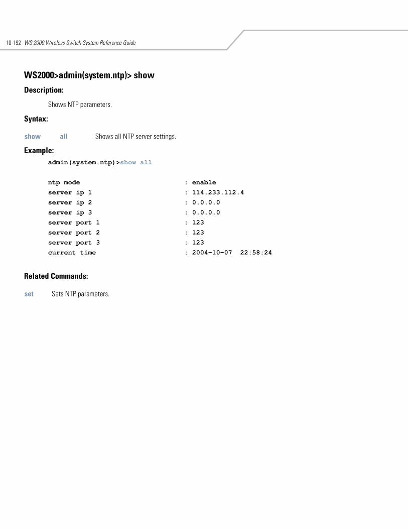
WS 2000 Wireless Switch System Reference Guide10-192
WS2000>admin(system.ntp)> show
Description:
Shows NTP parameters.
Syntax:
Example: admin(system.ntp)>show all
ntp mode : enable
server ip 1 : 114.233.112.4
server ip 2 : 0.0.0.0
server ip 3 : 0.0.0.0
server port 1 : 123
server port 2 : 123
server port 3 : 123
current time : 2004-10-07 22:58:24
Related Commands:
show all Shows all NTP server settings.
set Sets NTP parameters.
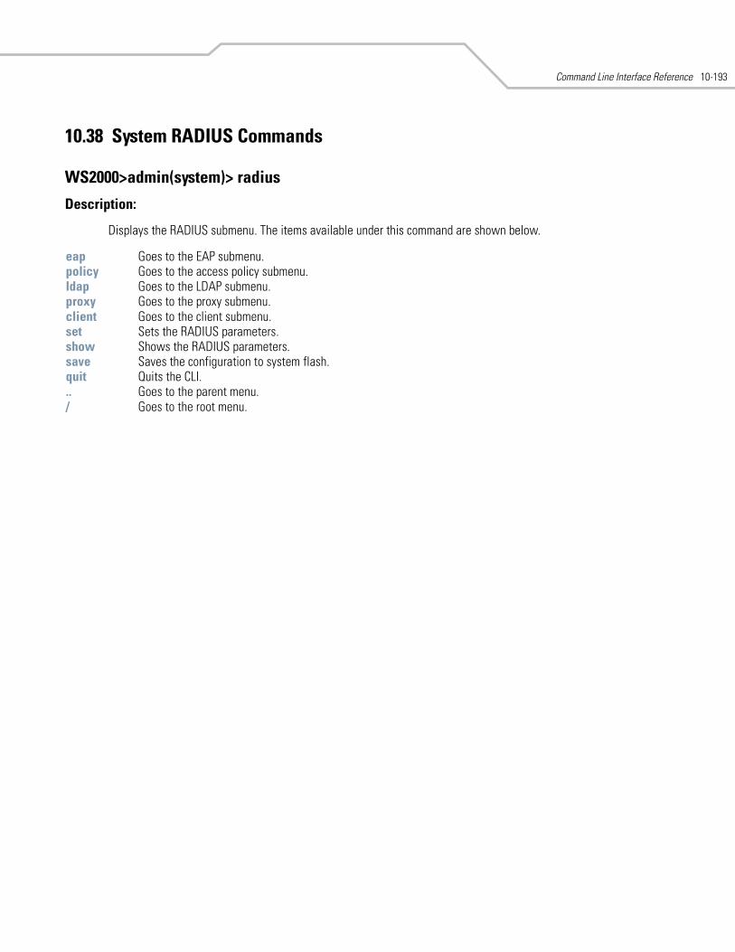
Command Line Interface Reference 10-193
10.38 System RADIUS Commands
WS2000>admin(system)> radius
Description:
Displays the RADIUS submenu. The items available under this command are shown below.
eap Goes to the EAP submenu.policy Goes to the access policy submenu. ldap Goes to the LDAP submenu.proxy Goes to the proxy submenu.client Goes to the client submenu.set Sets the RADIUS parameters.show Shows the RADIUS parameters.save Saves the configuration to system flash.quit Quits the CLI. .. Goes to the parent menu./ Goes to the root menu.
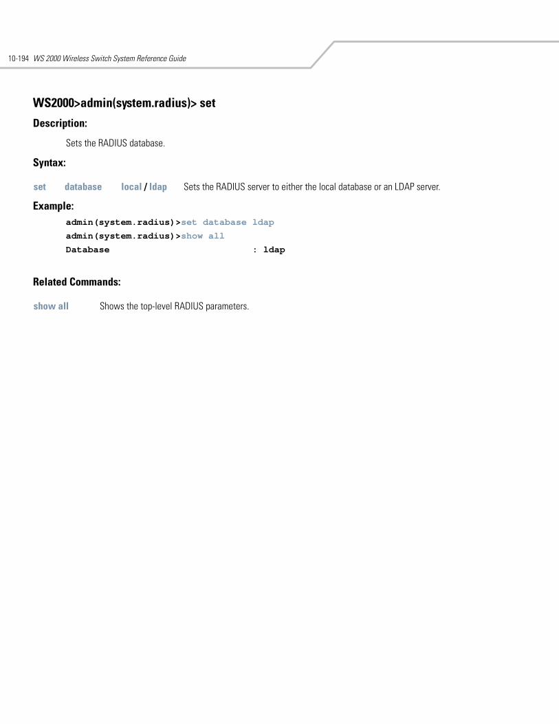
WS 2000 Wireless Switch System Reference Guide10-194
WS2000>admin(system.radius)> set
Description:
Sets the RADIUS database.
Syntax:
Example: admin(system.radius)>set database ldap
admin(system.radius)>show all
Database : ldap
Related Commands:
set database local / ldap Sets the RADIUS server to either the local database or an LDAP server.
show all Shows the top-level RADIUS parameters.
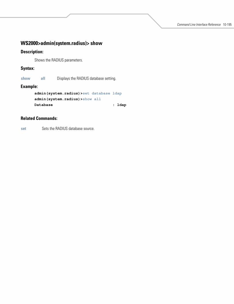
Command Line Interface Reference 10-195
WS2000>admin(system.radius)> show
Description:
Shows the RADIUS parameters.
Syntax:
Example: admin(system.radius)>set database ldap
admin(system.radius)>show all
Database : ldap
Related Commands:
show all Displays the RADIUS database setting.
set Sets the RADIUS database source.
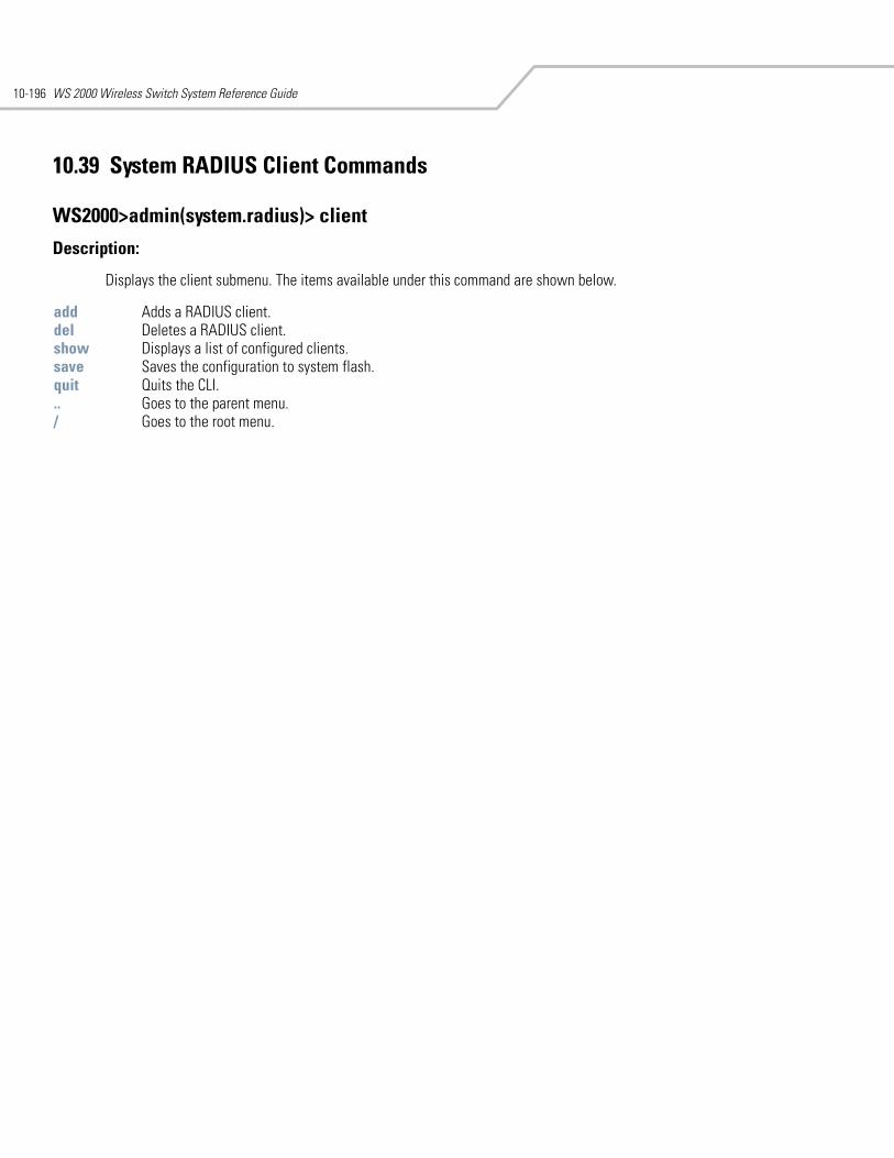
WS 2000 Wireless Switch System Reference Guide10-196
10.39 System RADIUS Client Commands
WS2000>admin(system.radius)> client
Description:
Displays the client submenu. The items available under this command are shown below.
add Adds a RADIUS client.del Deletes a RADIUS client.show Displays a list of configured clients. save Saves the configuration to system flash.quit Quits the CLI. .. Goes to the parent menu./ Goes to the root menu.
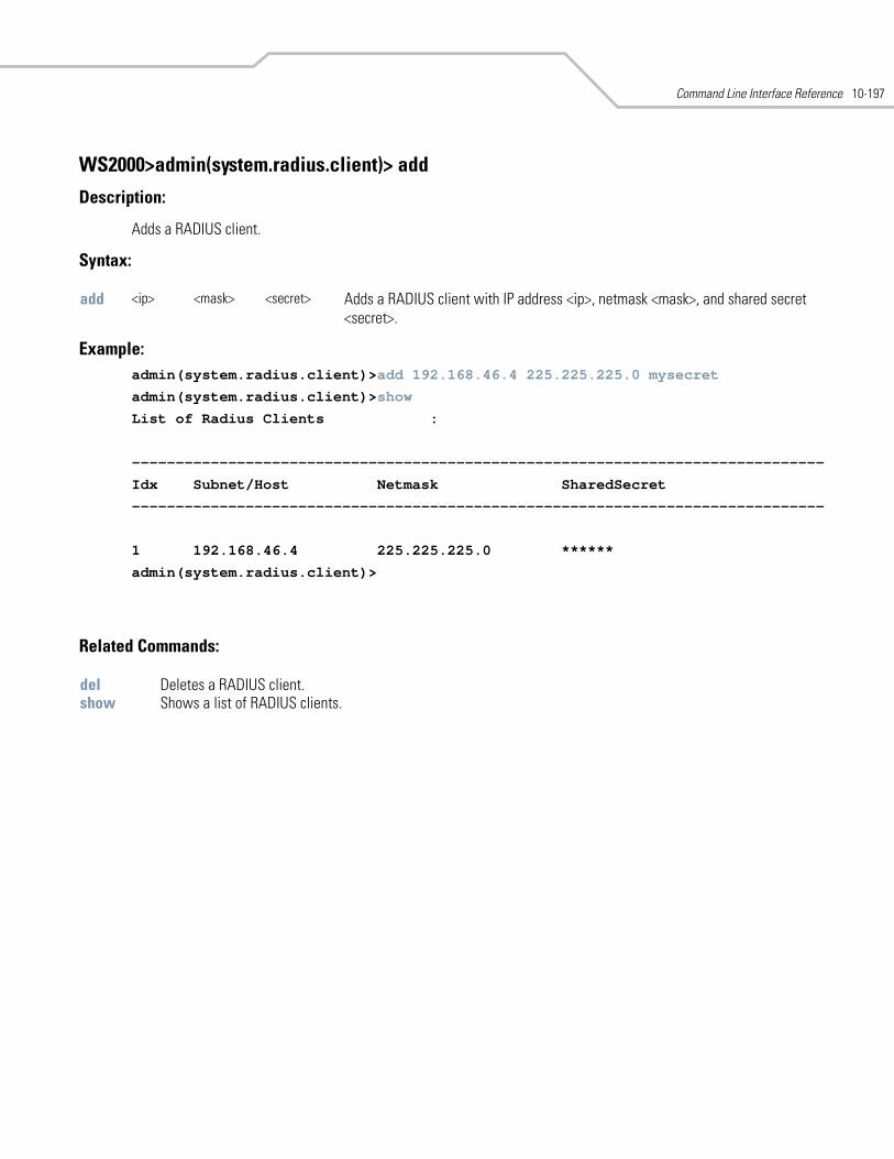
Command Line Interface Reference 10-197
WS2000>admin(system.radius.client)> add
Description:
Adds a RADIUS client.
Syntax:
Example: admin(system.radius.client)>add 192.168.46.4 225.225.225.0 mysecret
admin(system.radius.client)>show
List of Radius Clients :
-------------------------------------------------------------------------------
Idx Subnet/Host Netmask SharedSecret
-------------------------------------------------------------------------------
1 192.168.46.4 225.225.225.0 ******
admin(system.radius.client)>
Related Commands:
add <ip> <mask> <secret> Adds a RADIUS client with IP address <ip>, netmask <mask>, and shared secret <secret>.
del Deletes a RADIUS client.show Shows a list of RADIUS clients.
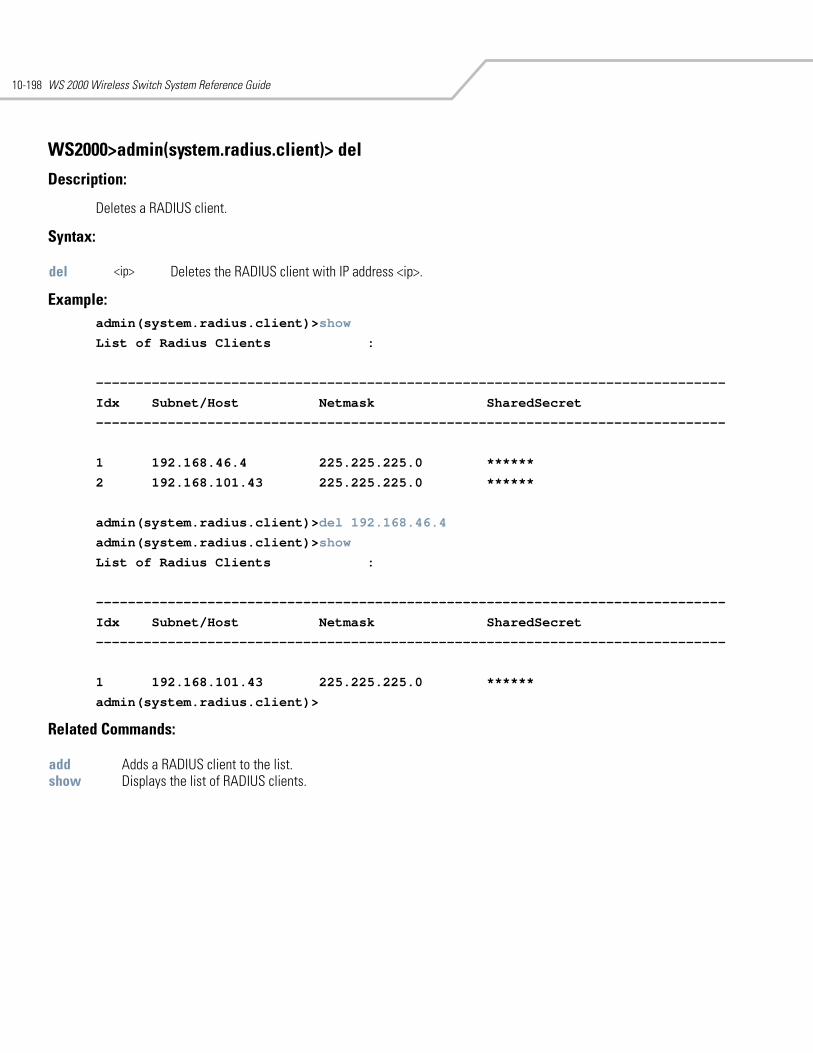
WS 2000 Wireless Switch System Reference Guide10-198
WS2000>admin(system.radius.client)> del
Description:
Deletes a RADIUS client.
Syntax:
Example: admin(system.radius.client)>show
List of Radius Clients :
-------------------------------------------------------------------------------
Idx Subnet/Host Netmask SharedSecret
-------------------------------------------------------------------------------
1 192.168.46.4 225.225.225.0 ******
2 192.168.101.43 225.225.225.0 ******
admin(system.radius.client)>del 192.168.46.4
admin(system.radius.client)>show
List of Radius Clients :
-------------------------------------------------------------------------------
Idx Subnet/Host Netmask SharedSecret
-------------------------------------------------------------------------------
1 192.168.101.43 225.225.225.0 ******
admin(system.radius.client)>
Related Commands:
del <ip> Deletes the RADIUS client with IP address <ip>.
add Adds a RADIUS client to the list.show Displays the list of RADIUS clients.
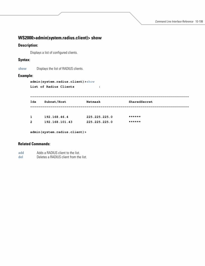
Command Line Interface Reference 10-199
WS2000>admin(system.radius.client)> show
Description:
Displays a list of configured clients.
Syntax:
Example: admin(system.radius.client)>show
List of Radius Clients :
-------------------------------------------------------------------------------
Idx Subnet/Host Netmask SharedSecret
-------------------------------------------------------------------------------
1 192.168.46.4 225.225.225.0 ******
2 192.168.101.43 225.225.225.0 ******
admin(system.radius.client)>
Related Commands:
show Displays the list of RADIUS clients.
add Adds a RADIUS client to the list.del Deletes a RADIUS client from the list.
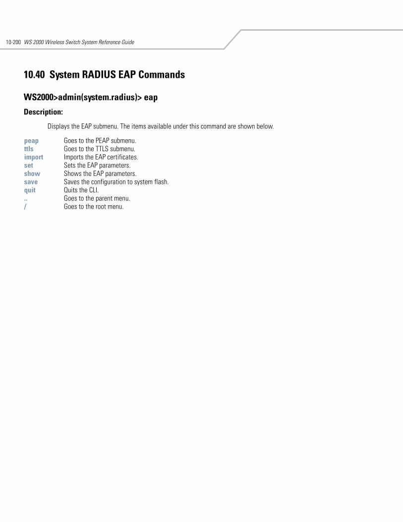
WS 2000 Wireless Switch System Reference Guide10-200
10.40 System RADIUS EAP Commands
WS2000>admin(system.radius)> eap
Description:
Displays the EAP submenu. The items available under this command are shown below.
peap Goes to the PEAP submenu.ttls Goes to the TTLS submenu. import Imports the EAP certificates.set Sets the EAP parameters.show Shows the EAP parameters.save Saves the configuration to system flash.quit Quits the CLI. .. Goes to the parent menu./ Goes to the root menu.
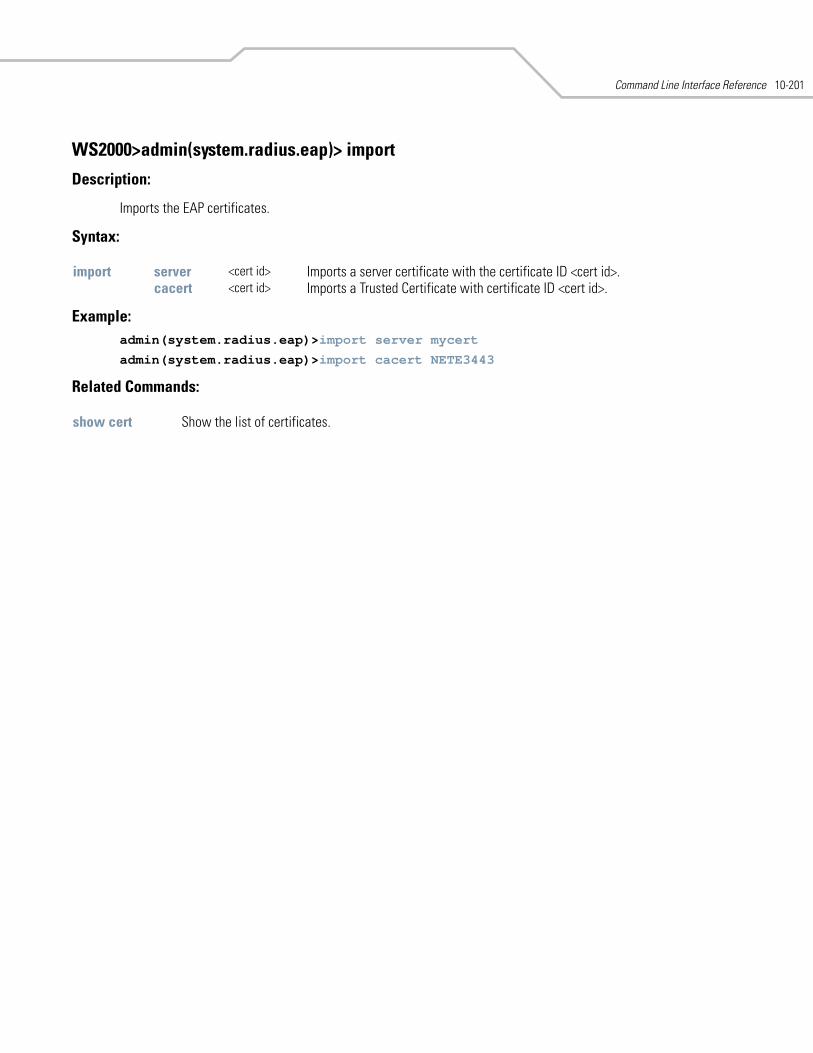
Command Line Interface Reference 10-201
WS2000>admin(system.radius.eap)> import
Description:
Imports the EAP certificates.
Syntax:
Example: admin(system.radius.eap)>import server mycert
admin(system.radius.eap)>import cacert NETE3443
Related Commands:
import server <cert id> Imports a server certificate with the certificate ID <cert id>.cacert <cert id> Imports a Trusted Certificate with certificate ID <cert id>.
show cert Show the list of certificates.
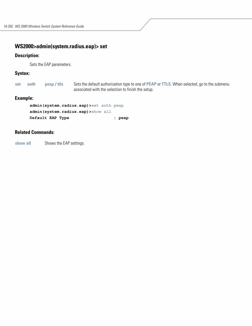
WS 2000 Wireless Switch System Reference Guide10-202
WS2000>admin(system.radius.eap)> set
Description:
Sets the EAP parameters.
Syntax:
Example: admin(system.radius.eap)>set auth peap
admin(system.radius.eap)>show all
Default EAP Type : peap
Related Commands:
set auth peap / ttls Sets the default authorization type to one of PEAP or TTLS. When selected, go to the submenu associated with the selection to finish the setup.
show all Shows the EAP settings.
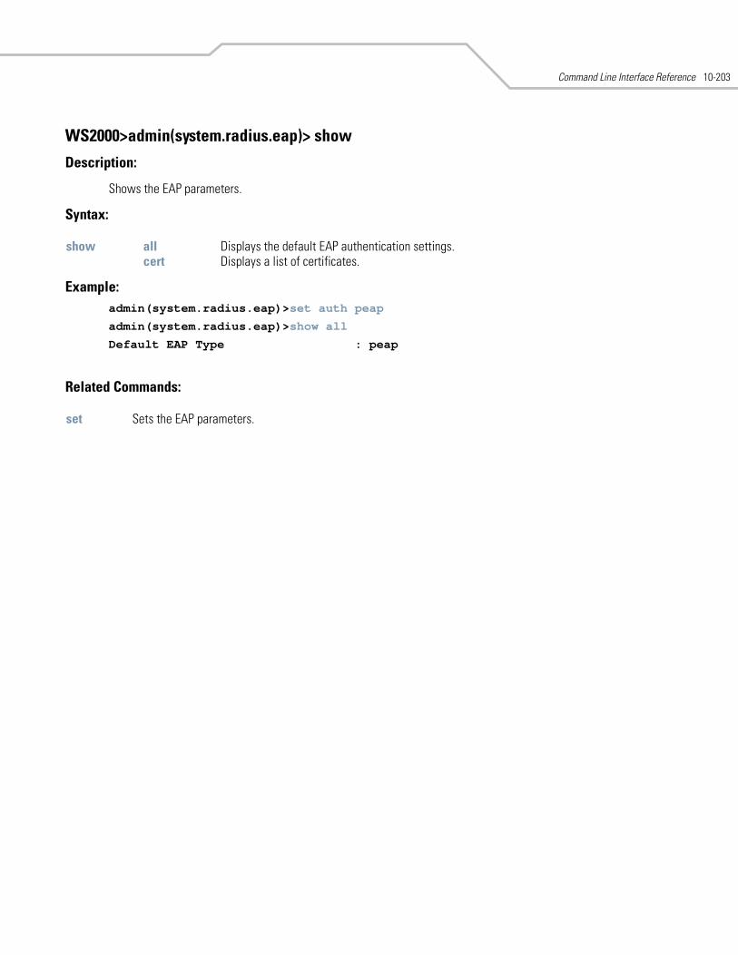
Command Line Interface Reference 10-203
WS2000>admin(system.radius.eap)> show
Description:
Shows the EAP parameters.
Syntax:
Example: admin(system.radius.eap)>set auth peap
admin(system.radius.eap)>show all
Default EAP Type : peap
Related Commands:
show all Displays the default EAP authentication settings.cert Displays a list of certificates.
set Sets the EAP parameters.
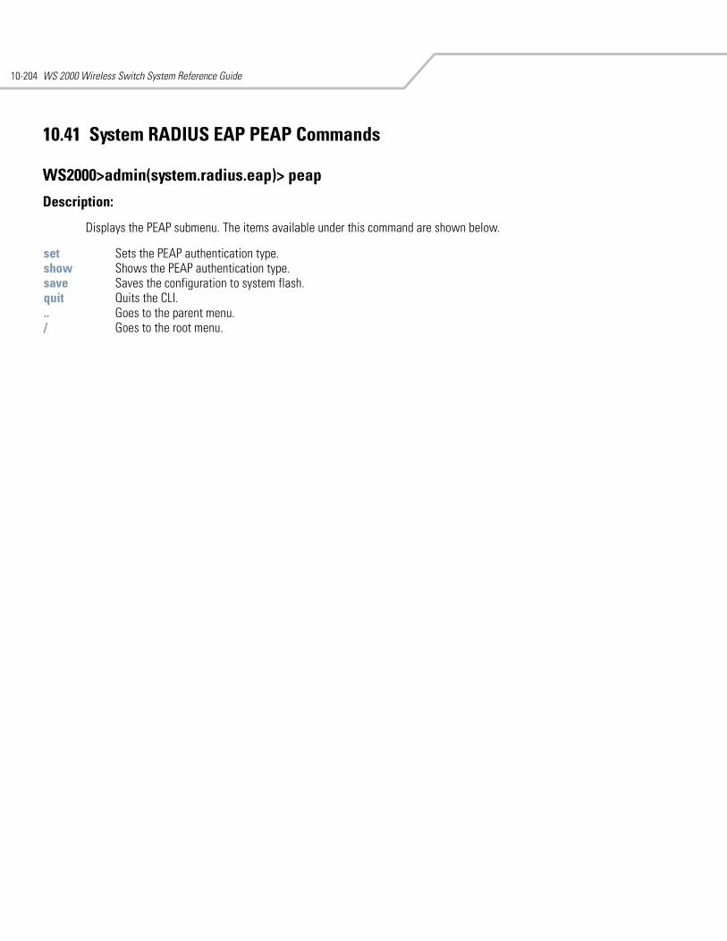
WS 2000 Wireless Switch System Reference Guide10-204
10.41 System RADIUS EAP PEAP Commands
WS2000>admin(system.radius.eap)> peap
Description:
Displays the PEAP submenu. The items available under this command are shown below.
set Sets the PEAP authentication type.show Shows the PEAP authentication type.save Saves the configuration to system flash.quit Quits the CLI. .. Goes to the parent menu./ Goes to the root menu.
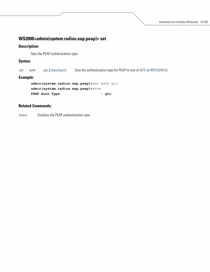
Command Line Interface Reference 10-205
WS2000>admin(system.radius.eap.peap)> set
Description:
Sets the PEAP authentication type.
Syntax:
Example: admin(system.radius.eap.peap)>set auth gtc
admin(system.radius.eap.peap)>show
PEAP Auth Type : gtc
Related Commands:
set auth gtc / mschapv2 Sets the authentication type for PEAP to one of GTC or MTCHAPv2.
show Displays the PEAP authentication type.
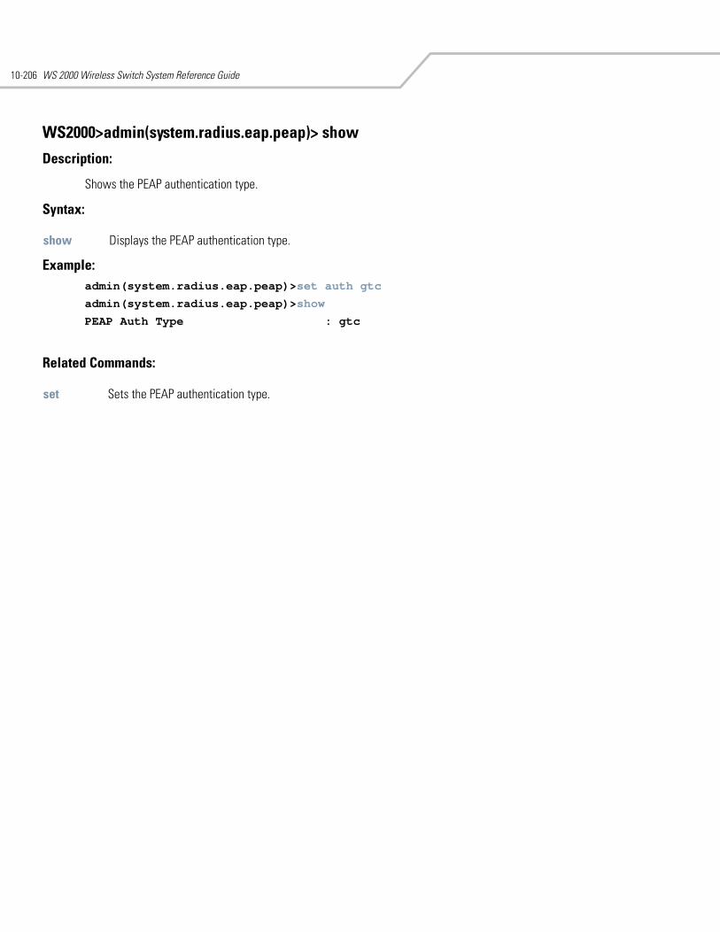
WS 2000 Wireless Switch System Reference Guide10-206
WS2000>admin(system.radius.eap.peap)> show
Description:
Shows the PEAP authentication type.
Syntax:
Example: admin(system.radius.eap.peap)>set auth gtc
admin(system.radius.eap.peap)>show
PEAP Auth Type : gtc
Related Commands:
show Displays the PEAP authentication type.
set Sets the PEAP authentication type.
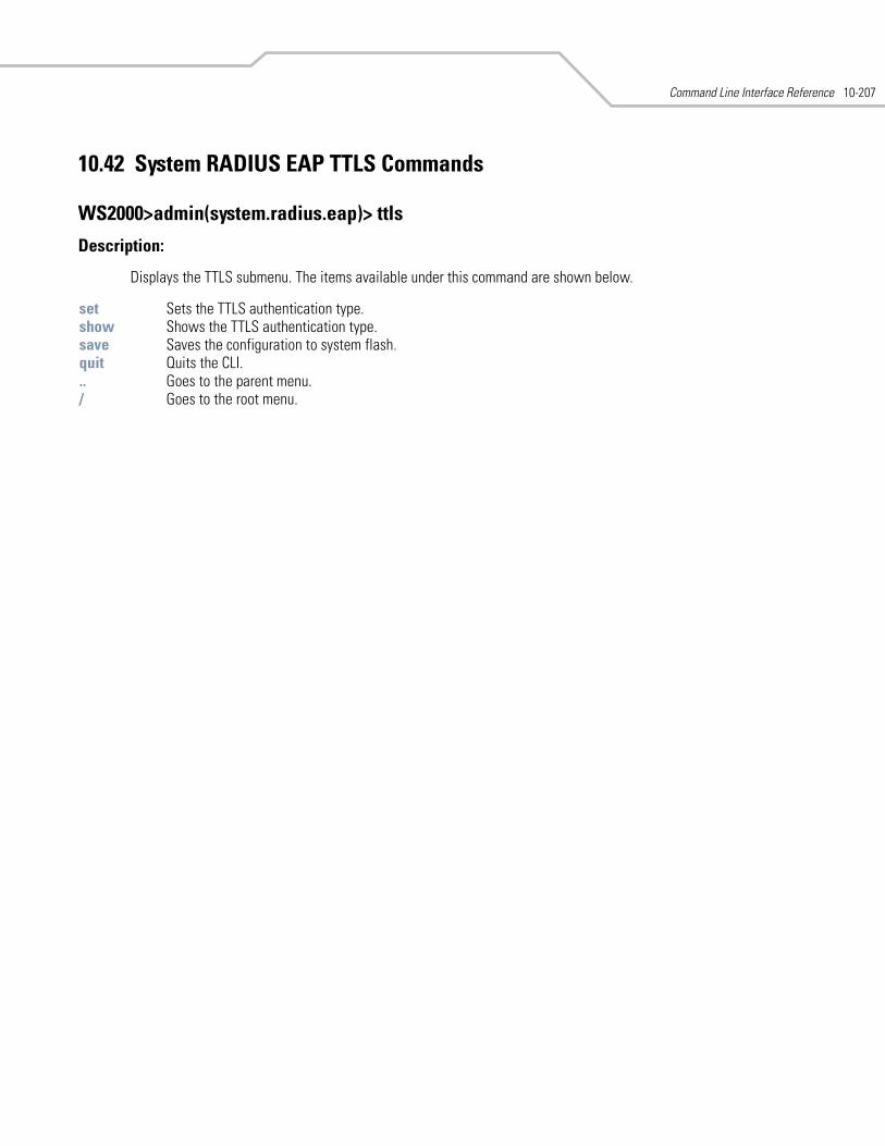
Command Line Interface Reference 10-207
10.42 System RADIUS EAP TTLS Commands
WS2000>admin(system.radius.eap)> ttls
Description:
Displays the TTLS submenu. The items available under this command are shown below.
set Sets the TTLS authentication type.show Shows the TTLS authentication type.save Saves the configuration to system flash.quit Quits the CLI. .. Goes to the parent menu./ Goes to the root menu.
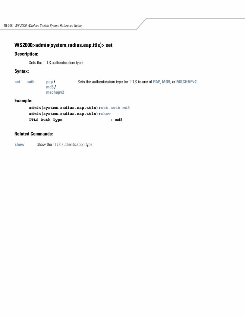
WS 2000 Wireless Switch System Reference Guide10-208
WS2000>admin(system.radius.eap.ttls)> set
Description:
Sets the TTLS authentication type.
Syntax:
Example: admin(system.radius.eap.ttls)>set auth md5
admin(system.radius.eap.ttls)>show
TTLS Auth Type : md5
Related Commands:
set auth pap /md5 /mschapv2
Sets the authentication type for TTLS to one of PAP, MD5, or MSCHAPv2.
show Show the TTLS authentication type.
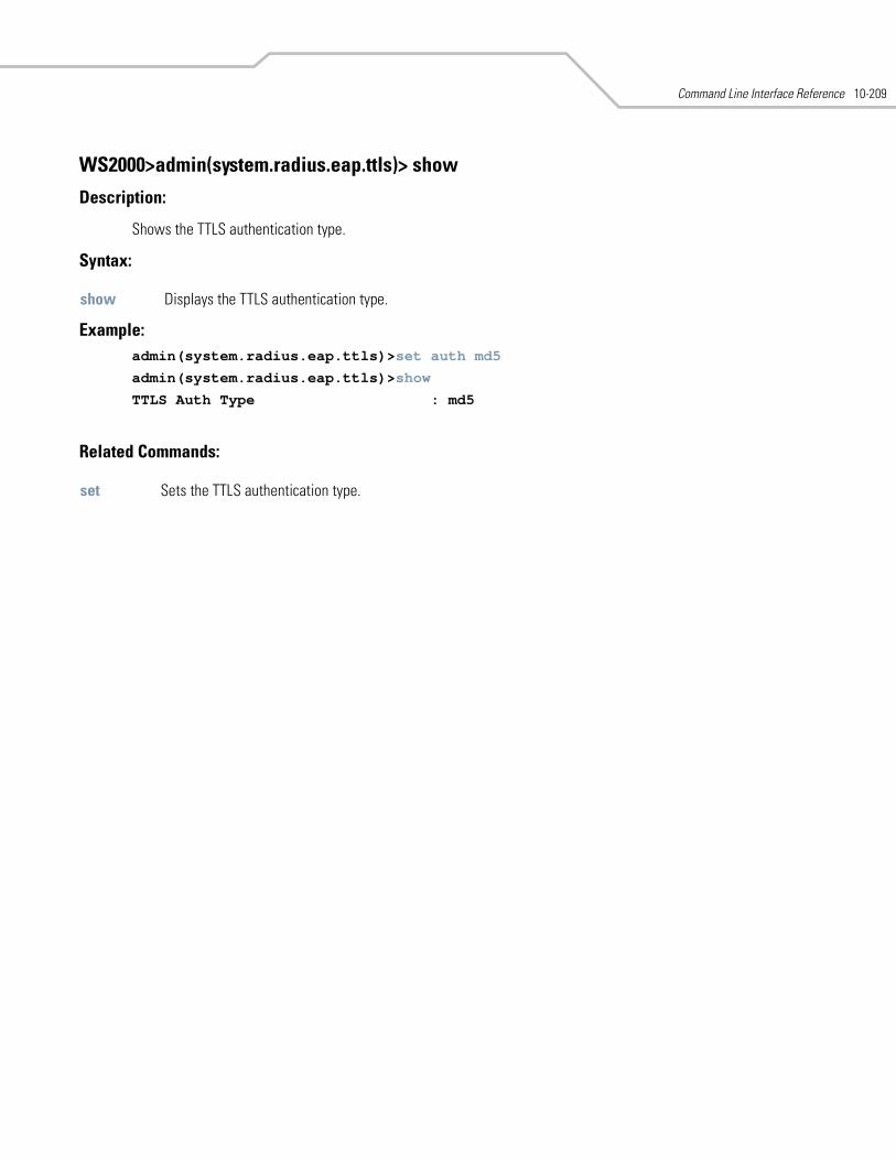
Command Line Interface Reference 10-209
WS2000>admin(system.radius.eap.ttls)> show
Description:
Shows the TTLS authentication type.
Syntax:
Example: admin(system.radius.eap.ttls)>set auth md5
admin(system.radius.eap.ttls)>show
TTLS Auth Type : md5
Related Commands:
show Displays the TTLS authentication type.
set Sets the TTLS authentication type.
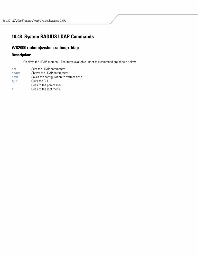
WS 2000 Wireless Switch System Reference Guide10-210
10.43 System RADIUS LDAP Commands
WS2000>admin(system.radius)> ldap
Description:
Displays the LDAP submenu. The items available under this command are shown below.
set Sets the LDAP parameters.show Shows the LDAP parameters.save Saves the configuration to system flash.quit Quits the CLI. .. Goes to the parent menu./ Goes to the root menu.
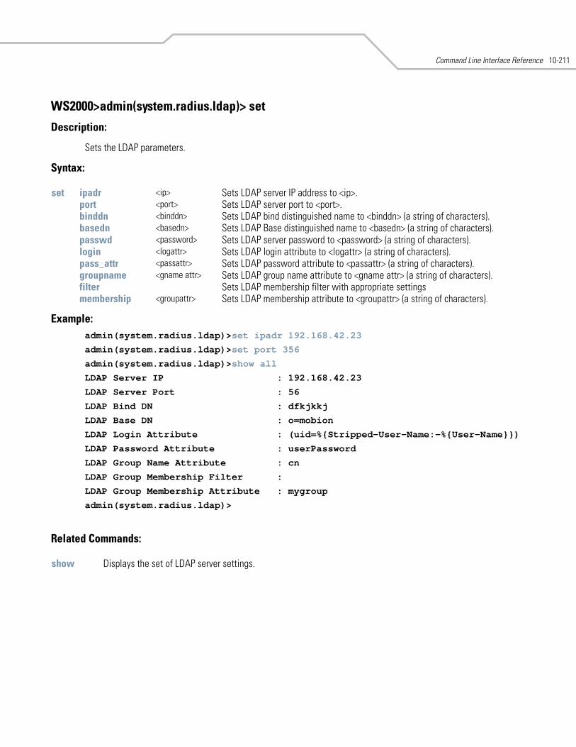
Command Line Interface Reference 10-211
WS2000>admin(system.radius.ldap)> set
Description:
Sets the LDAP parameters.
Syntax:
Example: admin(system.radius.ldap)>set ipadr 192.168.42.23
admin(system.radius.ldap)>set port 356
admin(system.radius.ldap)>show all
LDAP Server IP : 192.168.42.23
LDAP Server Port : 56
LDAP Bind DN : dfkjkkj
LDAP Base DN : o=mobion
LDAP Login Attribute : (uid=%{Stripped-User-Name:-%{User-Name}})
LDAP Password Attribute : userPassword
LDAP Group Name Attribute : cn
LDAP Group Membership Filter :
LDAP Group Membership Attribute : mygroup
admin(system.radius.ldap)>
Related Commands:
set ipadr <ip> Sets LDAP server IP address to <ip>.port <port> Sets LDAP server port to <port>.binddn <binddn> Sets LDAP bind distinguished name to <binddn> (a string of characters).basedn <basedn> Sets LDAP Base distinguished name to <basedn> (a string of characters).passwd <password> Sets LDAP server password to <password> (a string of characters).login <logattr> Sets LDAP login attribute to <logattr> (a string of characters).pass_attr <passattr> Sets LDAP password attribute to <passattr> (a string of characters).groupname <gname attr> Sets LDAP group name attribute to <gname attr> (a string of characters).filter Sets LDAP membership filter with appropriate settingsmembership <groupattr> Sets LDAP membership attribute to <groupattr> (a string of characters).
show Displays the set of LDAP server settings.
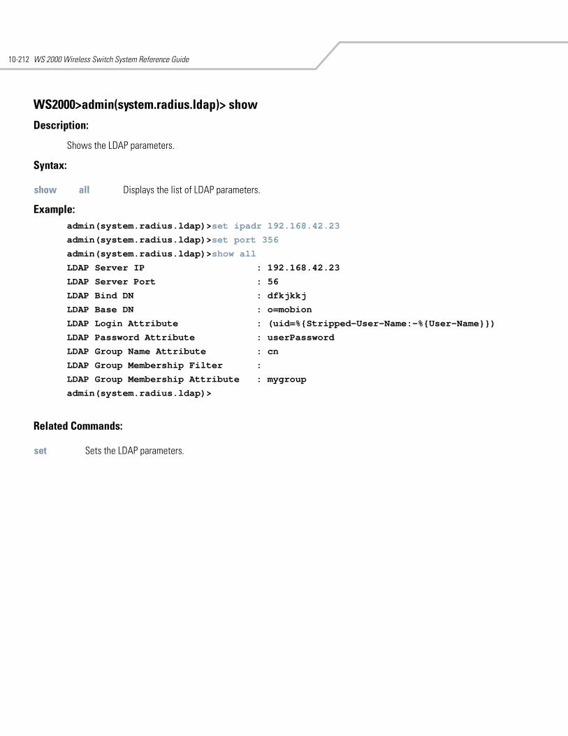
WS 2000 Wireless Switch System Reference Guide10-212
WS2000>admin(system.radius.ldap)> show
Description:
Shows the LDAP parameters.
Syntax:
Example: admin(system.radius.ldap)>set ipadr 192.168.42.23
admin(system.radius.ldap)>set port 356
admin(system.radius.ldap)>show all
LDAP Server IP : 192.168.42.23
LDAP Server Port : 56
LDAP Bind DN : dfkjkkj
LDAP Base DN : o=mobion
LDAP Login Attribute : (uid=%{Stripped-User-Name:-%{User-Name}})
LDAP Password Attribute : userPassword
LDAP Group Name Attribute : cn
LDAP Group Membership Filter :
LDAP Group Membership Attribute : mygroup
admin(system.radius.ldap)>
Related Commands:
show all Displays the list of LDAP parameters.
set Sets the LDAP parameters.

Command Line Interface Reference 10-213
10.44 System RADIUS Policy Commands
WS2000>admin(system.radius)> policy
Description:
Displays the policy submenu. The items available under this command are shown below.
set Sets the group’s access policy.show Shows the group’s access policy.save Saves the configuration to system flash.quit Quits the CLI. .. Goes to the parent menu./ Goes to the root menu.
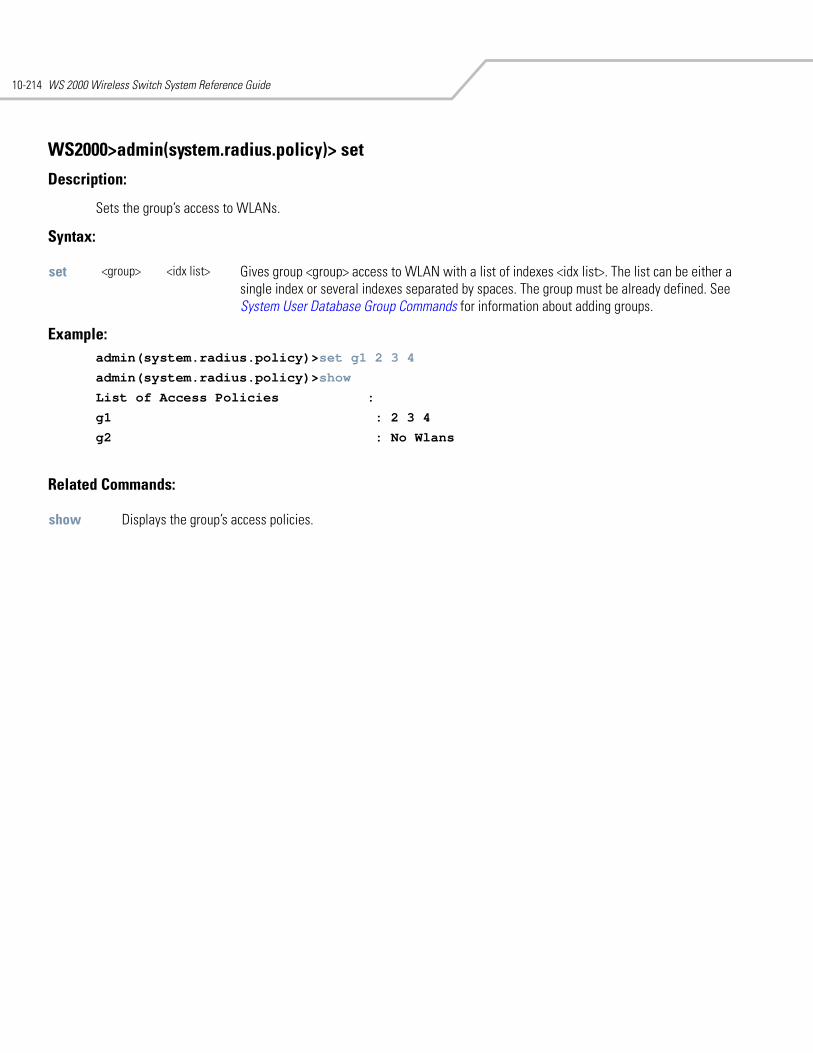
WS 2000 Wireless Switch System Reference Guide10-214
WS2000>admin(system.radius.policy)> set
Description:
Sets the group’s access to WLANs.
Syntax:
Example: admin(system.radius.policy)>set g1 2 3 4
admin(system.radius.policy)>show
List of Access Policies :
g1 : 2 3 4
g2 : No Wlans
Related Commands:
set <group> <idx list> Gives group <group> access to WLAN with a list of indexes <idx list>. The list can be either a single index or several indexes separated by spaces. The group must be already defined. See System User Database Group Commands for information about adding groups.
show Displays the group’s access policies.
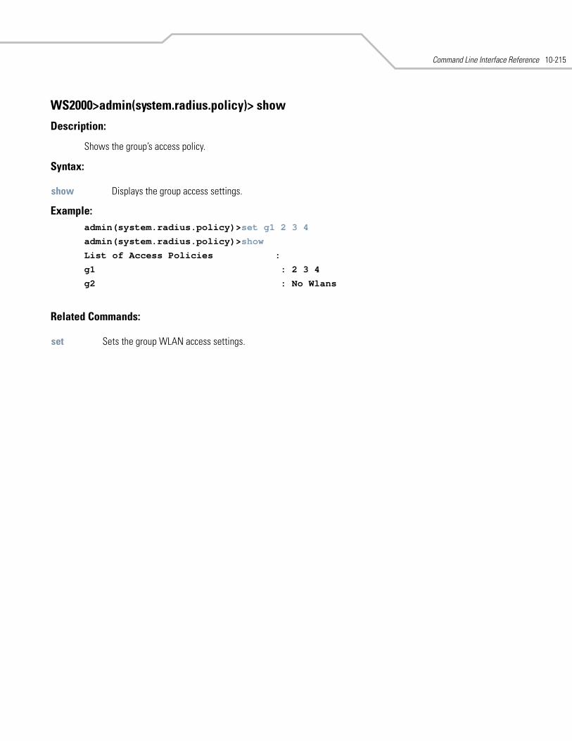
Command Line Interface Reference 10-215
WS2000>admin(system.radius.policy)> show
Description:
Shows the group’s access policy.
Syntax:
Example: admin(system.radius.policy)>set g1 2 3 4
admin(system.radius.policy)>show
List of Access Policies :
g1 : 2 3 4
g2 : No Wlans
Related Commands:
show Displays the group access settings.
set Sets the group WLAN access settings.
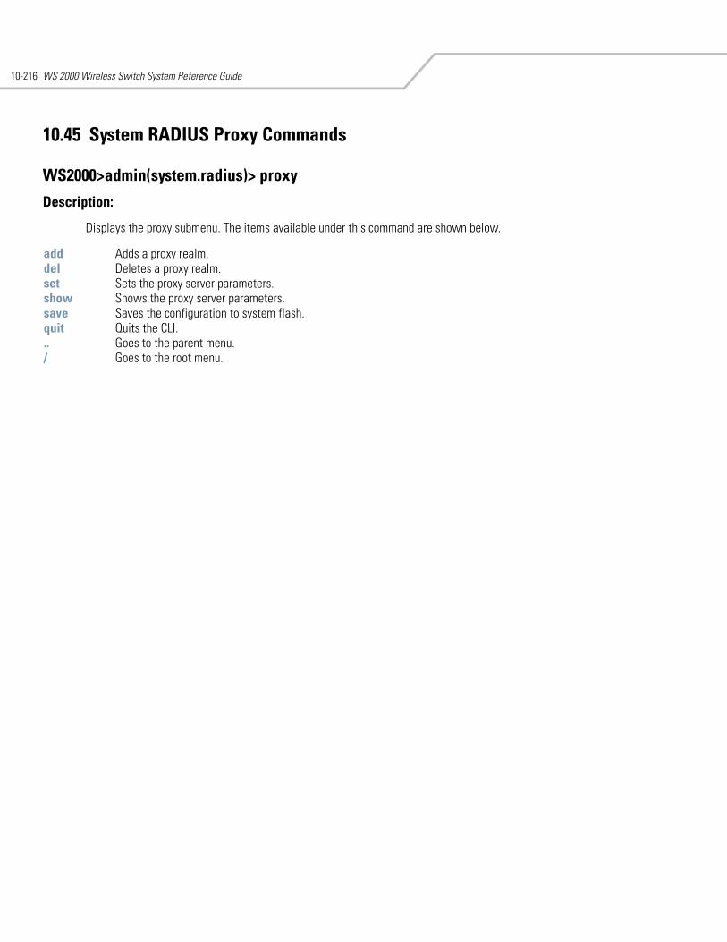
WS 2000 Wireless Switch System Reference Guide10-216
10.45 System RADIUS Proxy Commands
WS2000>admin(system.radius)> proxy
Description:
Displays the proxy submenu. The items available under this command are shown below.
add Adds a proxy realm. del Deletes a proxy realm.set Sets the proxy server parameters.show Shows the proxy server parameters.save Saves the configuration to system flash.quit Quits the CLI. .. Goes to the parent menu./ Goes to the root menu.
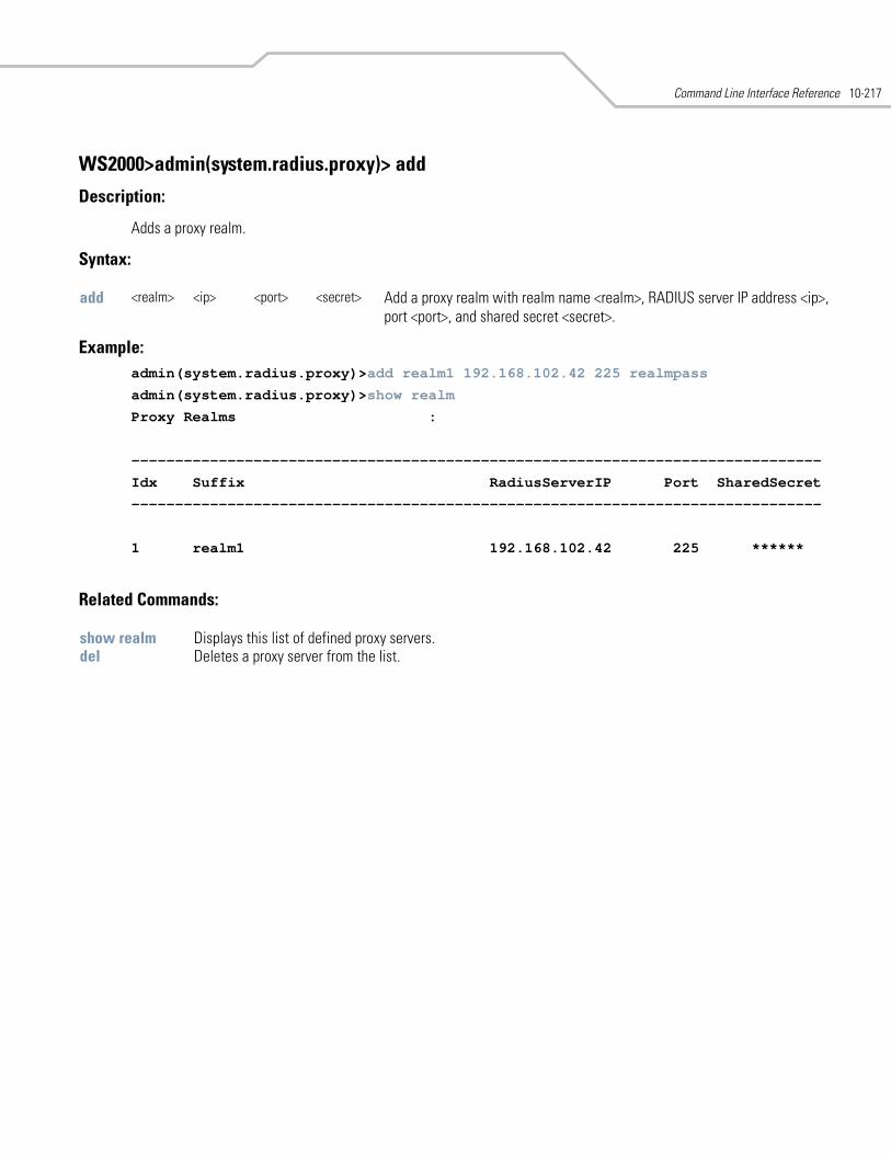
Command Line Interface Reference 10-217
WS2000>admin(system.radius.proxy)> add
Description:
Adds a proxy realm.
Syntax:
Example: admin(system.radius.proxy)>add realm1 192.168.102.42 225 realmpass
admin(system.radius.proxy)>show realm
Proxy Realms :
-------------------------------------------------------------------------------
Idx Suffix RadiusServerIP Port SharedSecret
-------------------------------------------------------------------------------
1 realm1 192.168.102.42 225 ******
Related Commands:
add <realm> <ip> <port> <secret> Add a proxy realm with realm name <realm>, RADIUS server IP address <ip>, port <port>, and shared secret <secret>.
show realm Displays this list of defined proxy servers.del Deletes a proxy server from the list.
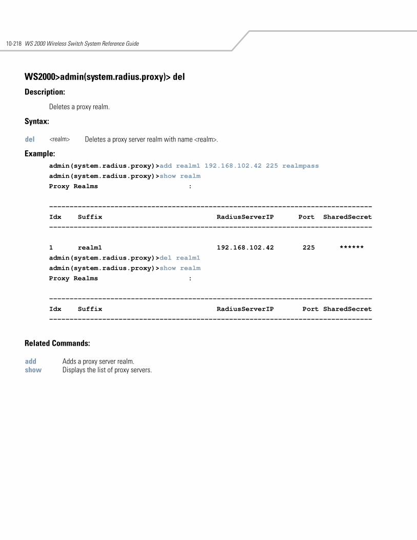
WS 2000 Wireless Switch System Reference Guide10-218
WS2000>admin(system.radius.proxy)> del
Description:
Deletes a proxy realm.
Syntax:
Example: admin(system.radius.proxy)>add realm1 192.168.102.42 225 realmpass
admin(system.radius.proxy)>show realm
Proxy Realms :
-------------------------------------------------------------------------------
Idx Suffix RadiusServerIP Port SharedSecret
-------------------------------------------------------------------------------
1 realm1 192.168.102.42 225 ******
admin(system.radius.proxy)>del realm1
admin(system.radius.proxy)>show realm
Proxy Realms :
-------------------------------------------------------------------------------
Idx Suffix RadiusServerIP Port SharedSecret
-------------------------------------------------------------------------------
Related Commands:
del <realm> Deletes a proxy server realm with name <realm>.
add Adds a proxy server realm.show Displays the list of proxy servers.
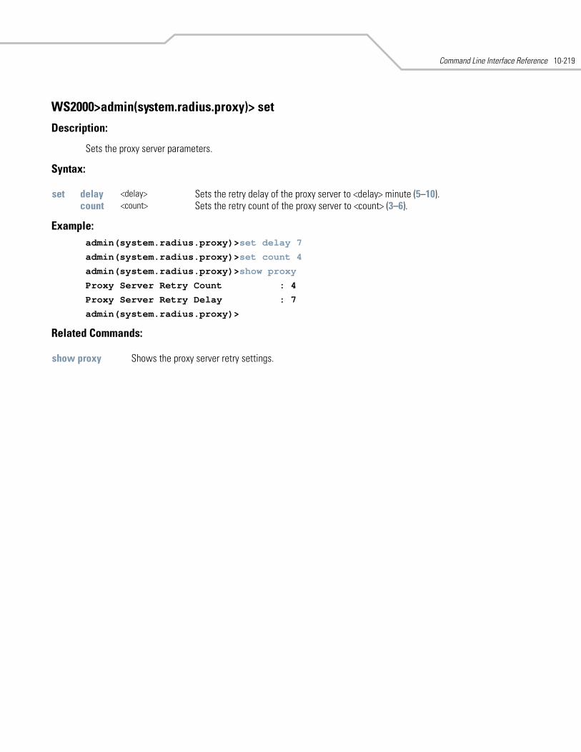
Command Line Interface Reference 10-219
WS2000>admin(system.radius.proxy)> set
Description:
Sets the proxy server parameters.
Syntax:
Example: admin(system.radius.proxy)>set delay 7
admin(system.radius.proxy)>set count 4
admin(system.radius.proxy)>show proxy
Proxy Server Retry Count : 4
Proxy Server Retry Delay : 7
admin(system.radius.proxy)>
Related Commands:
set delay <delay> Sets the retry delay of the proxy server to <delay> minute (5–10).count <count> Sets the retry count of the proxy server to <count> (3–6).
show proxy Shows the proxy server retry settings.
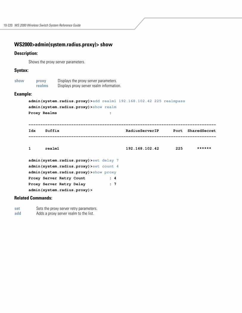
WS 2000 Wireless Switch System Reference Guide10-220
WS2000>admin(system.radius.proxy)> show
Description:
Shows the proxy server parameters.
Syntax:
Example: admin(system.radius.proxy)>add realm1 192.168.102.42 225 realmpass
admin(system.radius.proxy)>show realm
Proxy Realms :
-------------------------------------------------------------------------------
Idx Suffix RadiusServerIP Port SharedSecret
-------------------------------------------------------------------------------
1 realm1 192.168.102.42 225 ******
admin(system.radius.proxy)>set delay 7
admin(system.radius.proxy)>set count 4
admin(system.radius.proxy)>show proxy
Proxy Server Retry Count : 4
Proxy Server Retry Delay : 7
admin(system.radius.proxy)>
Related Commands:
show proxy Displays the proxy server parameters. realms Displays proxy server realm information.
set Sets the proxy server retry parameters.add Adds a proxy server realm to the list.
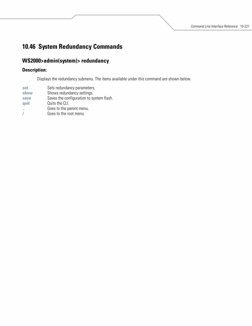
Command Line Interface Reference 10-221
10.46 System Redundancy Commands
WS2000>admin(system)> redundancy
Description:
Displays the redundancy submenu. The items available under this command are shown below.
set Sets redundancy parameters.show Shows redundancy settings.save Saves the configuration to system flash.quit Quits the CLI. .. Goes to the parent menu./ Goes to the root menu.

WS 2000 Wireless Switch System Reference Guide10-222
WS2000>admin(system.redundancy)> set
Description:
Sets the parameters for redundant switch mode.
Syntax:
Example: admin(system.redundancy)>set mode standby
can not set the value when the op_state is either upgrade or standalone
admin(system.redundancy)>set op-state redundancy
admin(system.redundancy)>set mode standby
admin(system.redundancy)>
Related Commands:
set mode primary / standby
Tells the switch that it is either the primary or secondary (standby) switch when redun-dancy is enabled. This parameter can only be set if the op-state parameter is set to redundancy.
op-state upgrade / standalone / redundancy
Sets the redundancy operation state of the switch to one of:• standalone—The switch has no redundancy capabilities and operates independently
of any other WS 2000 switches on the network. This is the default setting.• redundancy—Two WS 2000 switches are connected, with one set as a primary and
the other as a standby.• upgrade—The primary and standby switches must run the same version of the switch
firmware for redundancy to work correctly. If the firmware on only one of the switches is updated, redundancy is disabled and the Operational State is automatically set to Upgrade.
heartbeat <interval> Sets the heartbeat interval for the switch to <interval> (1–60) seconds.revertdelay <delay> Specifies the amount of time (1–20 minutes) after not receiving a heartbeat packet before
the secondary (standby) switch will take over. hb_interface <port> Indicates which port on the switch (1–6) is the heart beat port. This is the port that con-
tains the Ethernet cable that attaches the two switches.
show Displays the redundancy settings.
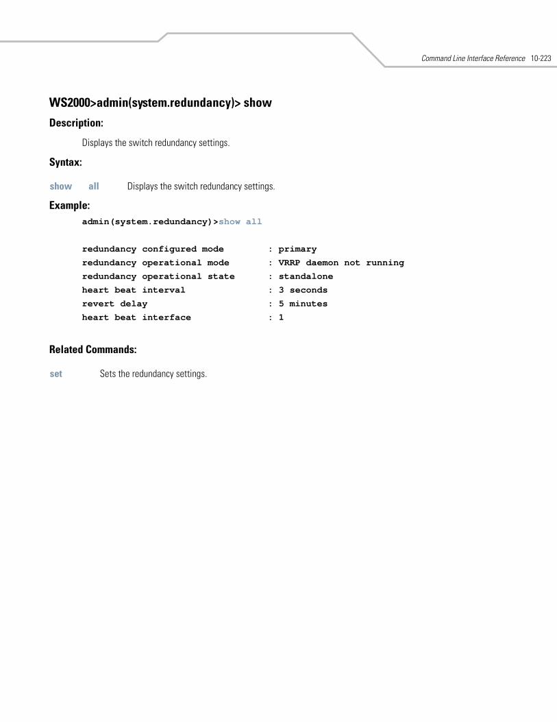
Command Line Interface Reference 10-223
WS2000>admin(system.redundancy)> show
Description:
Displays the switch redundancy settings.
Syntax:
Example: admin(system.redundancy)>show all
redundancy configured mode : primary
redundancy operational mode : VRRP daemon not running
redundancy operational state : standalone
heart beat interval : 3 seconds
revert delay : 5 minutes
heart beat interface : 1
Related Commands:
show all Displays the switch redundancy settings.
set Sets the redundancy settings.
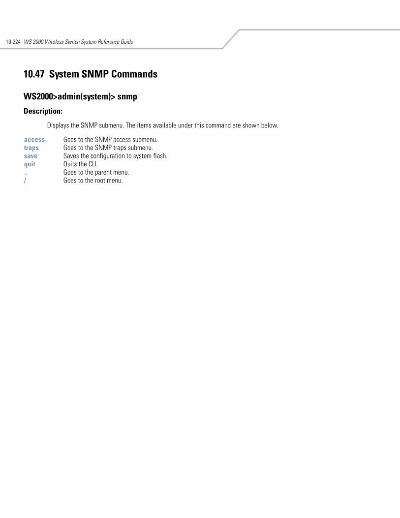
WS 2000 Wireless Switch System Reference Guide10-224
10.47 System SNMP Commands
WS2000>admin(system)> snmp
Description:
Displays the SNMP submenu. The items available under this command are shown below.
access Goes to the SNMP access submenu.traps Goes to the SNMP traps submenu. save Saves the configuration to system flash.quit Quits the CLI. .. Goes to the parent menu./ Goes to the root menu.
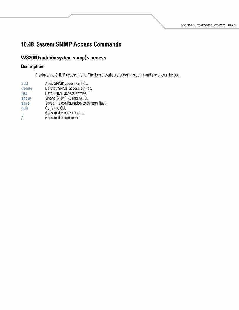
Command Line Interface Reference 10-225
10.48 System SNMP Access Commands
WS2000>admin(system.snmp)> access
Description:
Displays the SNMP access menu. The items available under this command are shown below.
add Adds SNMP access entries.delete Deletes SNMP access entries.list Lists SNMP access entries.show Shows SNMP v3 engine ID. save Saves the configuration to system flash.quit Quits the CLI. .. Goes to the parent menu./ Goes to the root menu.
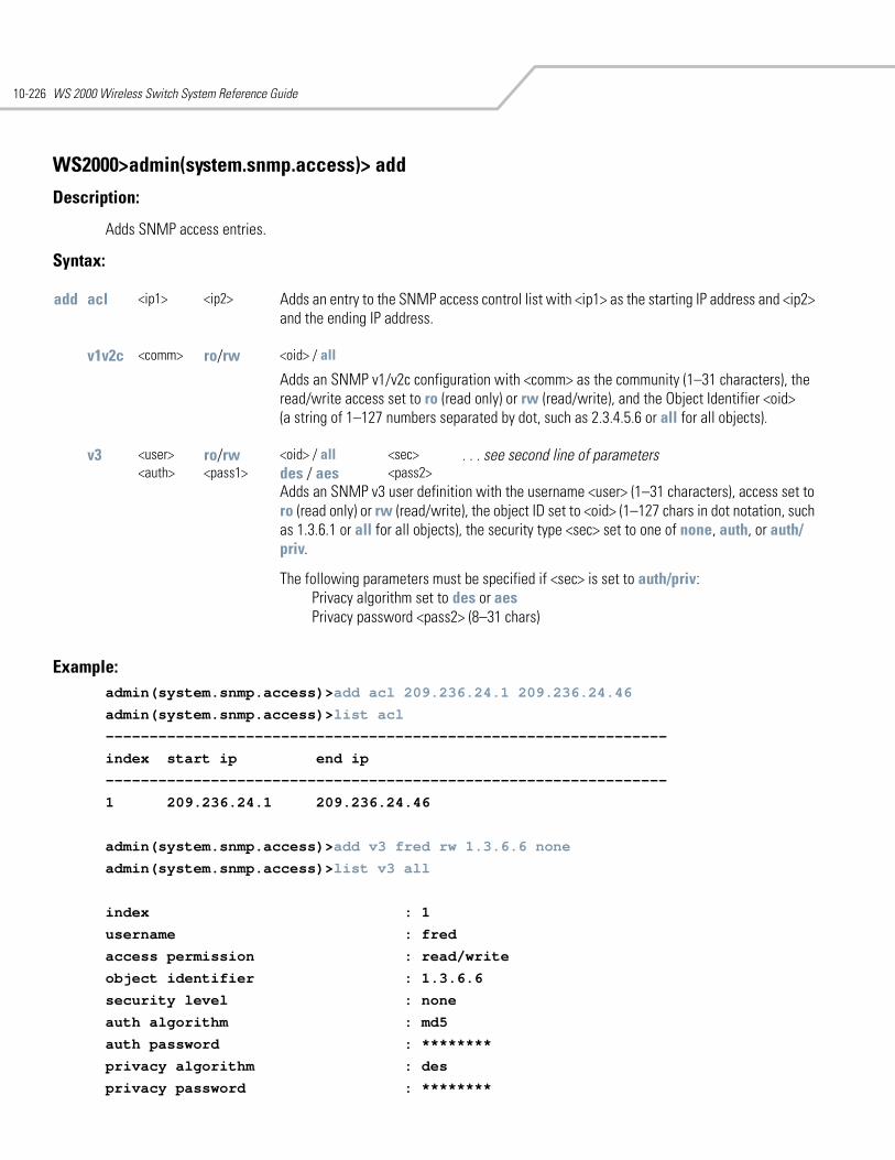
WS 2000 Wireless Switch System Reference Guide10-226
WS2000>admin(system.snmp.access)> add
Description:
Adds SNMP access entries.
Syntax:
Example: admin(system.snmp.access)>add acl 209.236.24.1 209.236.24.46
admin(system.snmp.access)>list acl
----------------------------------------------------------------
index start ip end ip
----------------------------------------------------------------
1 209.236.24.1 209.236.24.46
admin(system.snmp.access)>add v3 fred rw 1.3.6.6 none
admin(system.snmp.access)>list v3 all
index : 1
username : fred
access permission : read/write
object identifier : 1.3.6.6
security level : none
auth algorithm : md5
auth password : ********
privacy algorithm : des
privacy password : ********
add acl <ip1> <ip2> Adds an entry to the SNMP access control list with <ip1> as the starting IP address and <ip2> and the ending IP address.
v1v2c <comm> ro/rw <oid> / all
Adds an SNMP v1/v2c configuration with <comm> as the community (1–31 characters), the read/write access set to ro (read only) or rw (read/write), and the Object Identifier <oid> (a string of 1–127 numbers separated by dot, such as 2.3.4.5.6 or all for all objects).
v3 <user> ro/rw <oid> / all <sec> . . . see second line of parameters <auth> <pass1> des / aes <pass2>
Adds an SNMP v3 user definition with the username <user> (1–31 characters), access set to ro (read only) or rw (read/write), the object ID set to <oid> (1–127 chars in dot notation, such as 1.3.6.1 or all for all objects), the security type <sec> set to one of none, auth, or auth/priv.
The following parameters must be specified if <sec> is set to auth/priv: Privacy algorithm set to des or aes Privacy password <pass2> (8–31 chars)
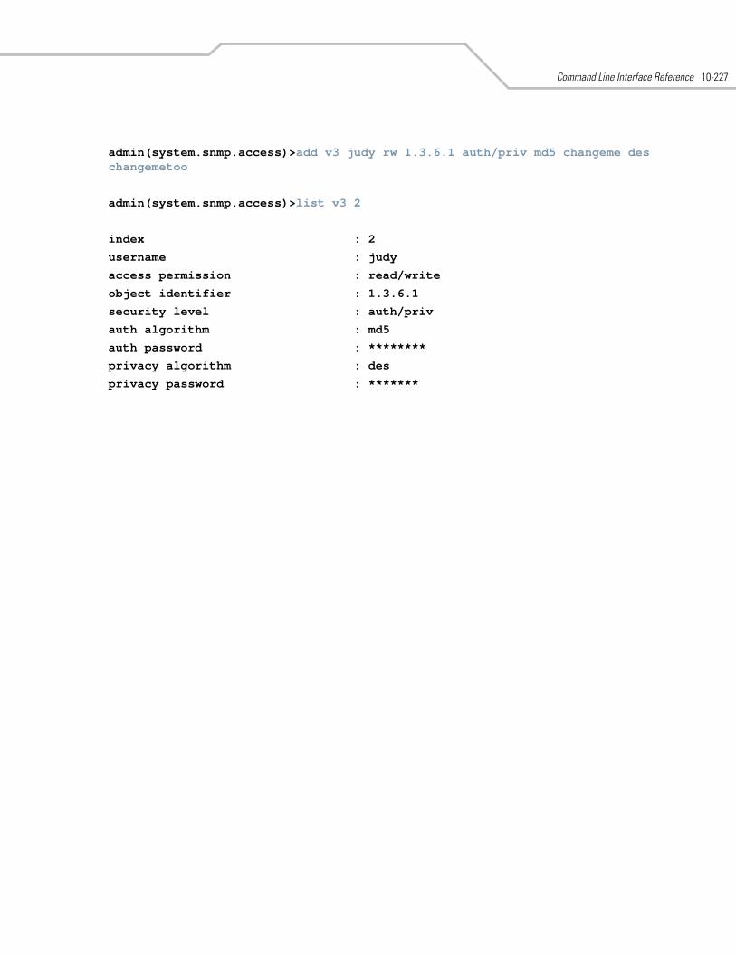
Command Line Interface Reference 10-227
admin(system.snmp.access)>add v3 judy rw 1.3.6.1 auth/priv md5 changeme des changemetoo
admin(system.snmp.access)>list v3 2
index : 2
username : judy
access permission : read/write
object identifier : 1.3.6.1
security level : auth/priv
auth algorithm : md5
auth password : ********
privacy algorithm : des
privacy password : *******
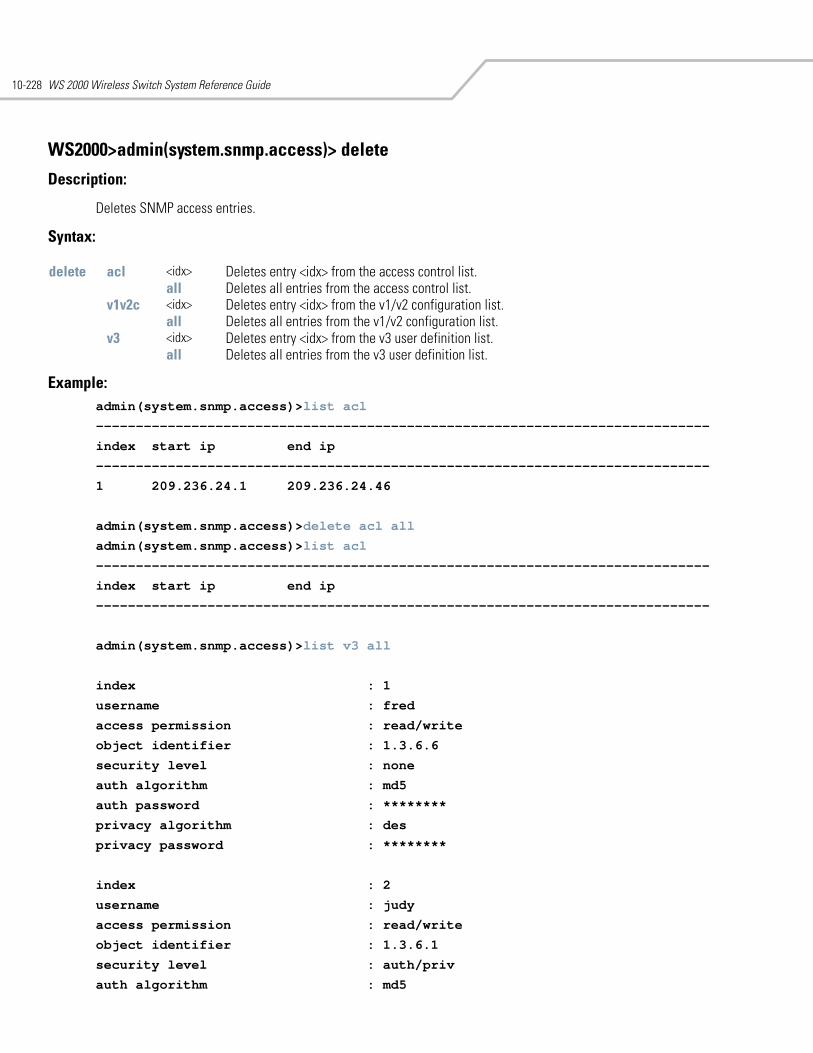
WS 2000 Wireless Switch System Reference Guide10-228
WS2000>admin(system.snmp.access)> delete
Description:
Deletes SNMP access entries.
Syntax:
Example:admin(system.snmp.access)>list acl
-----------------------------------------------------------------------------
index start ip end ip
-----------------------------------------------------------------------------
1 209.236.24.1 209.236.24.46
admin(system.snmp.access)>delete acl all
admin(system.snmp.access)>list acl
-----------------------------------------------------------------------------
index start ip end ip
-----------------------------------------------------------------------------
admin(system.snmp.access)>list v3 all
index : 1
username : fred
access permission : read/write
object identifier : 1.3.6.6
security level : none
auth algorithm : md5
auth password : ********
privacy algorithm : des
privacy password : ********
index : 2
username : judy
access permission : read/write
object identifier : 1.3.6.1
security level : auth/priv
auth algorithm : md5
delete acl <idx> Deletes entry <idx> from the access control list.all Deletes all entries from the access control list.
v1v2c <idx> Deletes entry <idx> from the v1/v2 configuration list.all Deletes all entries from the v1/v2 configuration list.
v3 <idx> Deletes entry <idx> from the v3 user definition list.all Deletes all entries from the v3 user definition list.
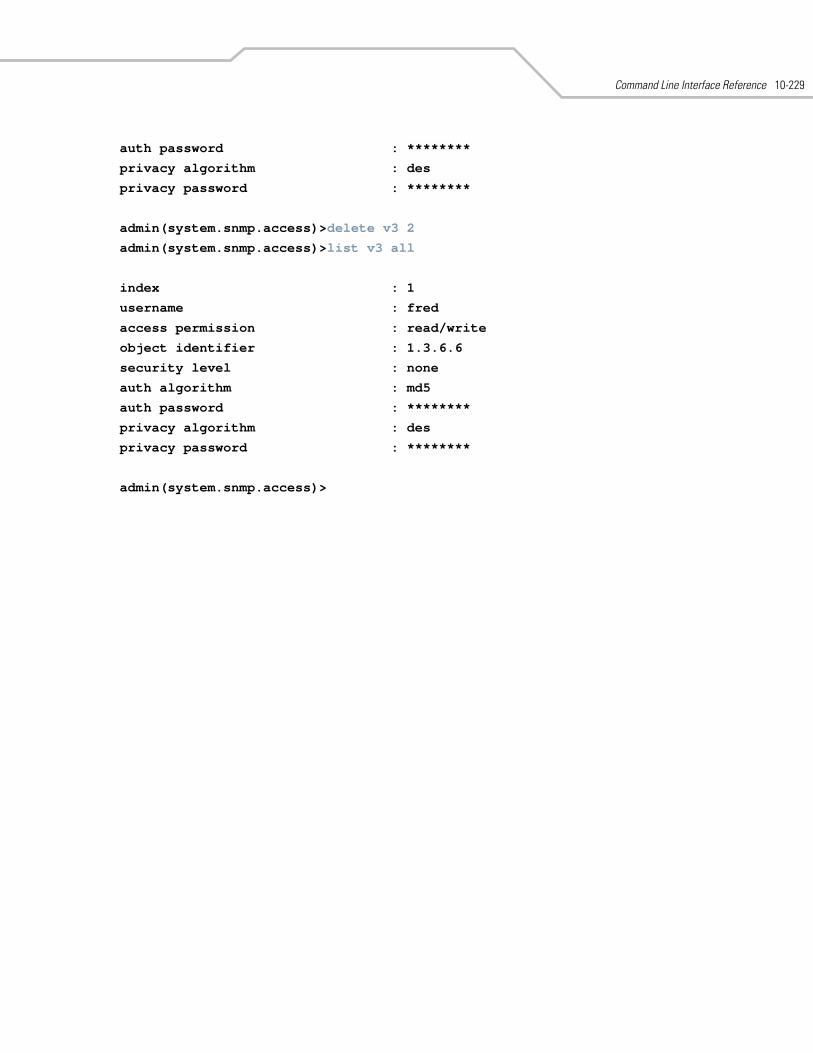
Command Line Interface Reference 10-229
auth password : ********
privacy algorithm : des
privacy password : ********
admin(system.snmp.access)>delete v3 2
admin(system.snmp.access)>list v3 all
index : 1
username : fred
access permission : read/write
object identifier : 1.3.6.6
security level : none
auth algorithm : md5
auth password : ********
privacy algorithm : des
privacy password : ********
admin(system.snmp.access)>
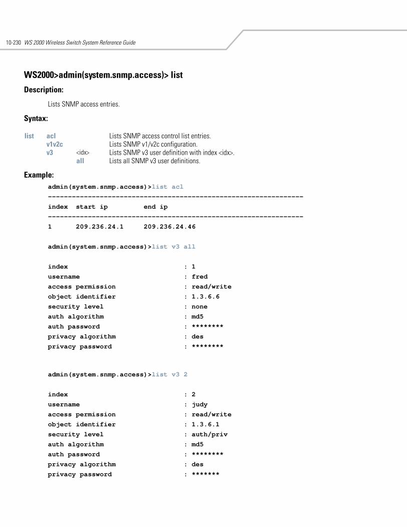
WS 2000 Wireless Switch System Reference Guide10-230
WS2000>admin(system.snmp.access)> list
Description:
Lists SNMP access entries.
Syntax:
Example:admin(system.snmp.access)>list acl
----------------------------------------------------------------
index start ip end ip
----------------------------------------------------------------
1 209.236.24.1 209.236.24.46
admin(system.snmp.access)>list v3 all
index : 1
username : fred
access permission : read/write
object identifier : 1.3.6.6
security level : none
auth algorithm : md5
auth password : ********
privacy algorithm : des
privacy password : ********
admin(system.snmp.access)>list v3 2
index : 2
username : judy
access permission : read/write
object identifier : 1.3.6.1
security level : auth/priv
auth algorithm : md5
auth password : ********
privacy algorithm : des
privacy password : *******
list acl Lists SNMP access control list entries.v1v2c Lists SNMP v1/v2c configuration.v3 <idx> Lists SNMP v3 user definition with index <idx>.
all Lists all SNMP v3 user definitions.
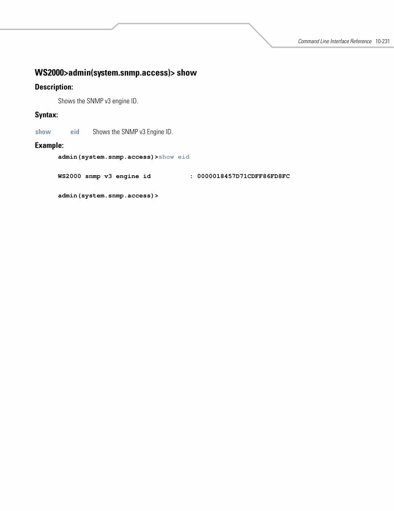
Command Line Interface Reference 10-231
WS2000>admin(system.snmp.access)> show
Description:
Shows the SNMP v3 engine ID.
Syntax:
Example: admin(system.snmp.access)>show eid
WS2000 snmp v3 engine id : 0000018457D71CDFF86FD8FC
admin(system.snmp.access)>
show eid Shows the SNMP v3 Engine ID.
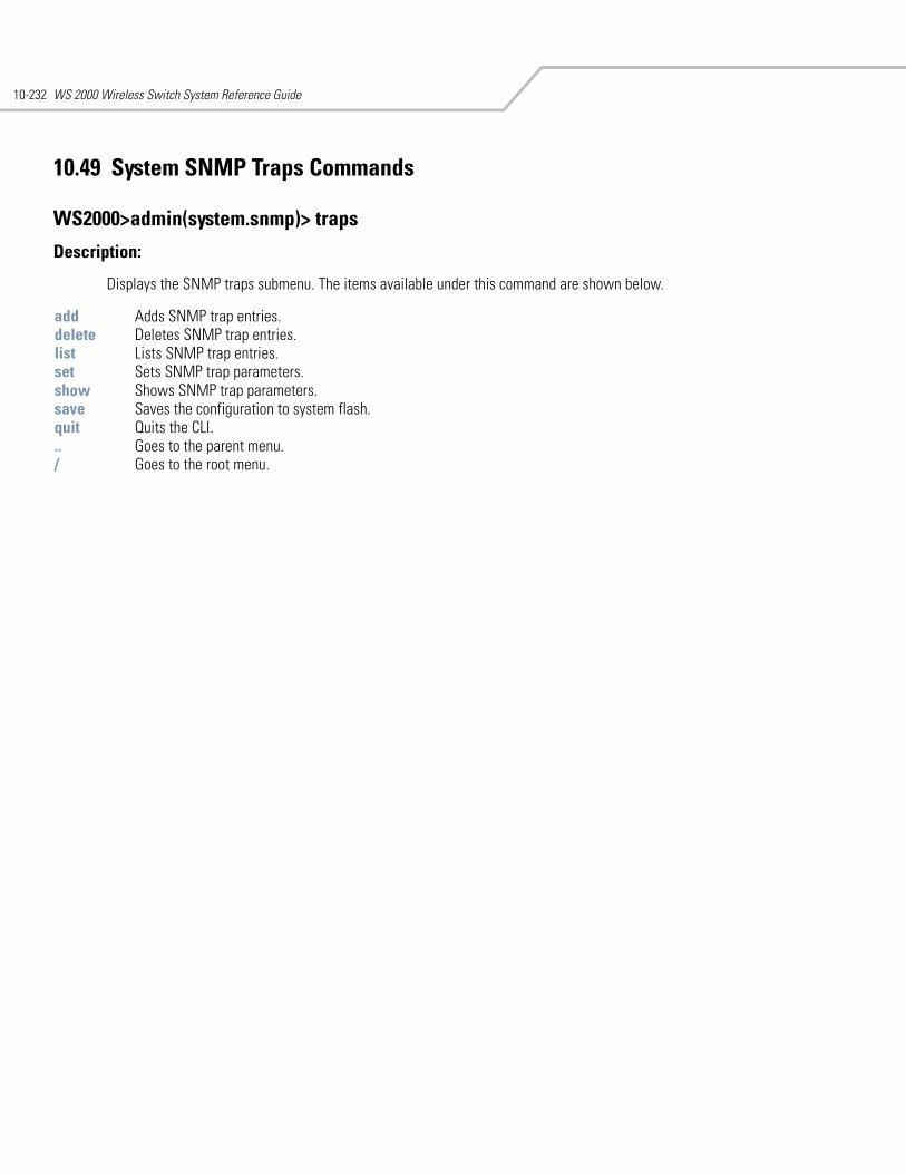
WS 2000 Wireless Switch System Reference Guide10-232
10.49 System SNMP Traps Commands
WS2000>admin(system.snmp)> traps
Description:
Displays the SNMP traps submenu. The items available under this command are shown below.
add Adds SNMP trap entries. delete Deletes SNMP trap entries. list Lists SNMP trap entries. set Sets SNMP trap parameters. show Shows SNMP trap parameters. save Saves the configuration to system flash.quit Quits the CLI. .. Goes to the parent menu./ Goes to the root menu.
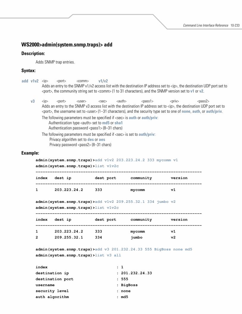
Command Line Interface Reference 10-233
WS2000>admin(system.snmp.traps)> add
Description:
Adds SNMP trap entries.
Syntax:
Example: admin(system.snmp.traps)>add v1v2 203.223.24.2 333 mycomm v1
admin(system.snmp.traps)>list v1v2c
----------------------------------------------------------------------
index dest ip dest port community version
----------------------------------------------------------------------
1 203.223.24.2 333 mycomm v1
admin(system.snmp.traps)>add v1v2 209.255.32.1 334 jumbo v2
admin(system.snmp.traps)>list v1v2c
----------------------------------------------------------------------
index dest ip dest port community version
----------------------------------------------------------------------
1 203.223.24.2 333 mycomm v1
2 209.255.32.1 334 jumbo v2
admin(system.snmp.traps)>add v3 201.232.24.33 555 BigBoss none md5
admin(system.snmp.traps)>list v3 all
index : 1
destination ip : 201.232.24.33
destination port : 555
username : BigBoss
security level : none
auth algorithm : md5
add v1v2 <ip> <port> <comm> v1/v2Adds an entry to the SNMP v1/v2 access list with the destination IP address set to <ip>, the destination UDP port set to <port>, the community string set to <comm> (1 to 31 characters), and the SNMP version set to v1 or v2.
v3 <ip> <port> <user> <sec> <auth> <pass1> <priv> <pass2>Adds an entry to the SNMP v3 access list with the destination IP address set to <ip>, the destination UDP port set to <port>, the username set to <user> (1–31 characters), and the security type set to one of none, auth, or auth/priv.The following parameters must be specified if <sec> is auth or auth/priv:
Authentication type <auth> set to md5 or sha1 Authentication password <pass1> (8–31 chars)
The following parameters must be specified if <sec> is set to auth/priv: Privacy algorithm set to des or aes Privacy password <pass2> (8–31 chars)
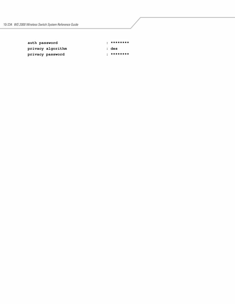
WS 2000 Wireless Switch System Reference Guide10-234
auth password : ********
privacy algorithm : des
privacy password : ********
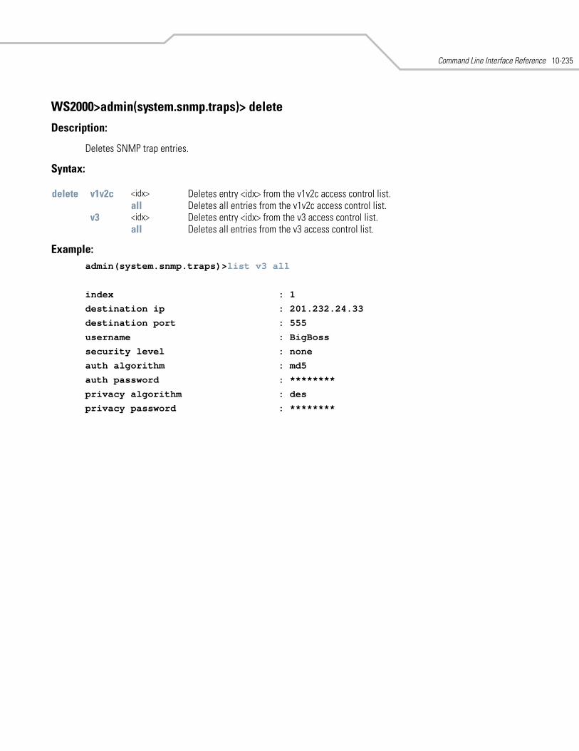
Command Line Interface Reference 10-235
WS2000>admin(system.snmp.traps)> delete
Description:
Deletes SNMP trap entries.
Syntax:
Example: admin(system.snmp.traps)>list v3 all
index : 1
destination ip : 201.232.24.33
destination port : 555
username : BigBoss
security level : none
auth algorithm : md5
auth password : ********
privacy algorithm : des
privacy password : ********
delete v1v2c <idx> Deletes entry <idx> from the v1v2c access control list.all Deletes all entries from the v1v2c access control list.
v3 <idx> Deletes entry <idx> from the v3 access control list.all Deletes all entries from the v3 access control list.
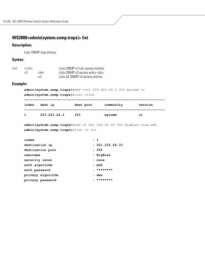
WS 2000 Wireless Switch System Reference Guide10-236
WS2000>admin(system.snmp.traps)> list
Description:
Lists SNMP trap entries.
Syntax:
Example: admin(system.snmp.traps)>add v1v2 203.223.24.2 333 mycomm v1
admin(system.snmp.traps)>list v1v2c
----------------------------------------------------------------------
index dest ip dest port community version
----------------------------------------------------------------------
1 203.223.24.2 333 mycomm v1
admin(system.snmp.traps)>add v3 201.232.24.33 555 BigBoss none md5
admin(system.snmp.traps)>list v3 all
index : 1
destination ip : 201.232.24.33
destination port : 555
username : BigBoss
security level : none
auth algorithm : md5
auth password : ********
privacy algorithm : des
privacy password : ********
list v1v2c Lists SNMP v1/v2c access entries.v3 <idx> Lists SNMP v3 access entry <idx>.
all Lists all SNMP v3 access entries.
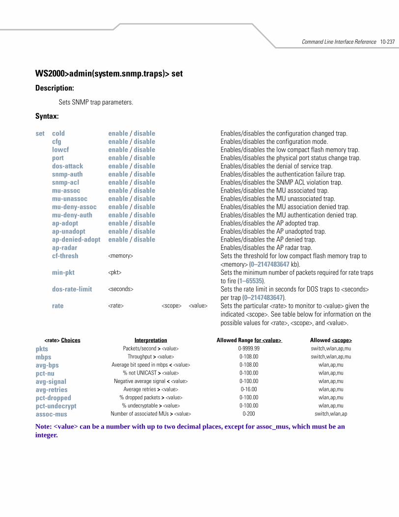
Command Line Interface Reference 10-237
WS2000>admin(system.snmp.traps)> set
Description:
Sets SNMP trap parameters.
Syntax:
Note: <value> can be a number with up to two decimal places, except for assoc_mus, which must be an integer.
set cold enable / disable Enables/disables the configuration changed trap.cfg enable / disable Enables/disables the configuration mode.lowcf enable / disable Enables/disables the low compact flash memory trap.port enable / disable Enables/disables the physical port status change trap.dos-attack enable / disable Enables/disables the denial of service trap.snmp-auth enable / disable Enables/disables the authentication failure trap.snmp-acl enable / disable Enables/disables the SNMP ACL violation trap.mu-assoc enable / disable Enables/disables the MU associated trap.mu-unassoc enable / disable Enables/disables the MU unassociated trap.mu-deny-assoc enable / disable Enables/disables the MU association denied trap.mu-deny-auth enable / disable Enables/disables the MU authentication denied trap.ap-adopt enable / disable Enables/disables the AP adopted trap.ap-unadopt enable / disable Enables/disables the AP unadopted trap.ap-denied-adopt enable / disable Enables/disables the AP denied trap.ap-radar Enables/disables the AP radar trap.cf-thresh <memory> Sets the threshold for low compact flash memory trap to
<memory> (0–2147483647 kb). min-pkt <pkt> Sets the minimum number of packets required for rate traps
to fire (1–65535). dos-rate-limit <seconds> Sets the rate limit in seconds for DOS traps to <seconds>
per trap (0–2147483647). rate <rate> <scope> <value> Sets the particular <rate> to monitor to <value> given the
indicated <scope>. See table below for information on the possible values for <rate>, <scope>, and <value>.
<rate> Choices Interpretation Allowed Range for <value> Allowed <scope>
pkts Packets/second > <value> 0-9999.99 switch,wlan,ap,mu
mbps Throughput > <value> 0-108.00 switch,wlan,ap,mu
avg-bps Average bit speed in mbps < <value> 0-108.00 wlan,ap,mu
pct-nu % not UNICAST > <value> 0-100.00 wlan,ap,mu
avg-signal Negative average signal < <value> 0-100.00 wlan,ap,mu
avg-retries Average retries > <value> 0-16.00 wlan,ap,mu
pct-dropped % dropped packets > <value> 0-100.00 wlan,ap,mu
pct-undecrypt % undecryptable > <value> 0-100.00 wlan,ap,mu
assoc-mus Number of associated MUs > <value> 0-200 switch,wlan,ap
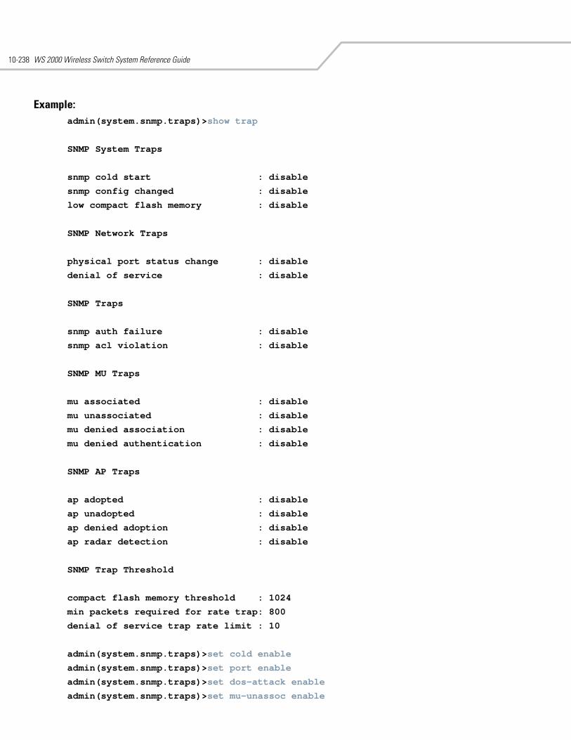
WS 2000 Wireless Switch System Reference Guide10-238
Example:admin(system.snmp.traps)>show trap
SNMP System Traps
snmp cold start : disable
snmp config changed : disable
low compact flash memory : disable
SNMP Network Traps
physical port status change : disable
denial of service : disable
SNMP Traps
snmp auth failure : disable
snmp acl violation : disable
SNMP MU Traps
mu associated : disable
mu unassociated : disable
mu denied association : disable
mu denied authentication : disable
SNMP AP Traps
ap adopted : disable
ap unadopted : disable
ap denied adoption : disable
ap radar detection : disable
SNMP Trap Threshold
compact flash memory threshold : 1024
min packets required for rate trap: 800
denial of service trap rate limit : 10
admin(system.snmp.traps)>set cold enable
admin(system.snmp.traps)>set port enable
admin(system.snmp.traps)>set dos-attack enable
admin(system.snmp.traps)>set mu-unassoc enable
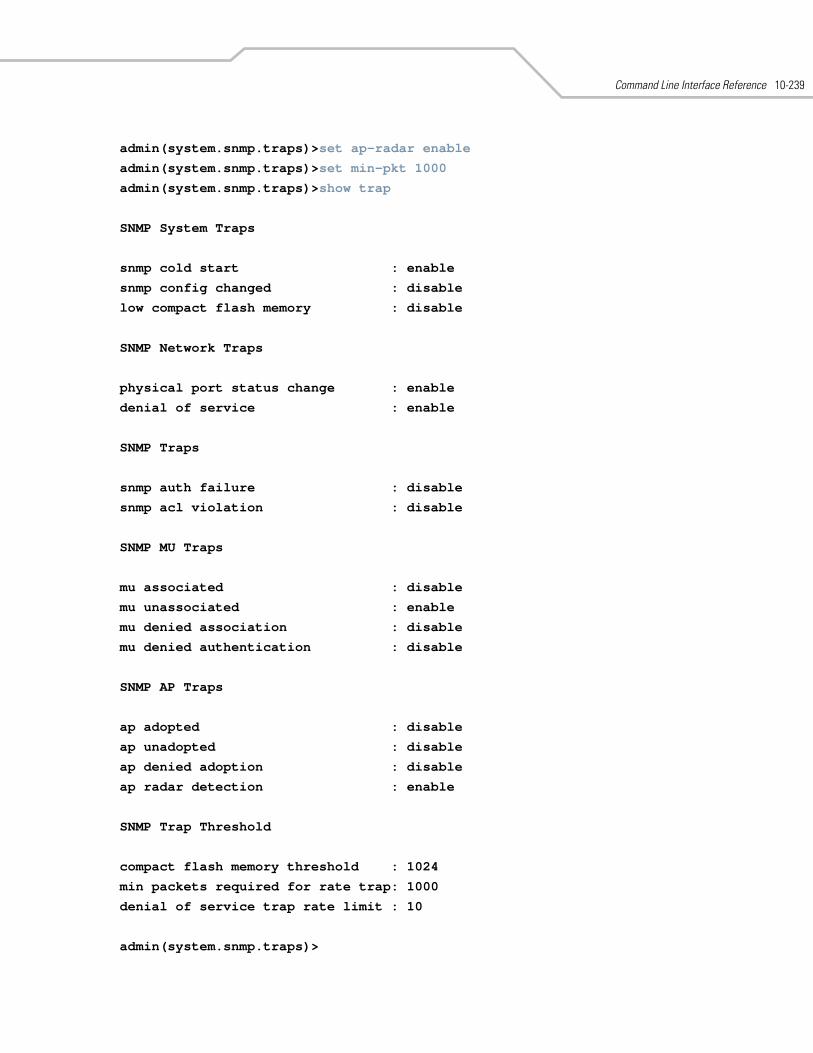
Command Line Interface Reference 10-239
admin(system.snmp.traps)>set ap-radar enable
admin(system.snmp.traps)>set min-pkt 1000
admin(system.snmp.traps)>show trap
SNMP System Traps
snmp cold start : enable
snmp config changed : disable
low compact flash memory : disable
SNMP Network Traps
physical port status change : enable
denial of service : enable
SNMP Traps
snmp auth failure : disable
snmp acl violation : disable
SNMP MU Traps
mu associated : disable
mu unassociated : enable
mu denied association : disable
mu denied authentication : disable
SNMP AP Traps
ap adopted : disable
ap unadopted : disable
ap denied adoption : disable
ap radar detection : enable
SNMP Trap Threshold
compact flash memory threshold : 1024
min packets required for rate trap: 1000
denial of service trap rate limit : 10
admin(system.snmp.traps)>
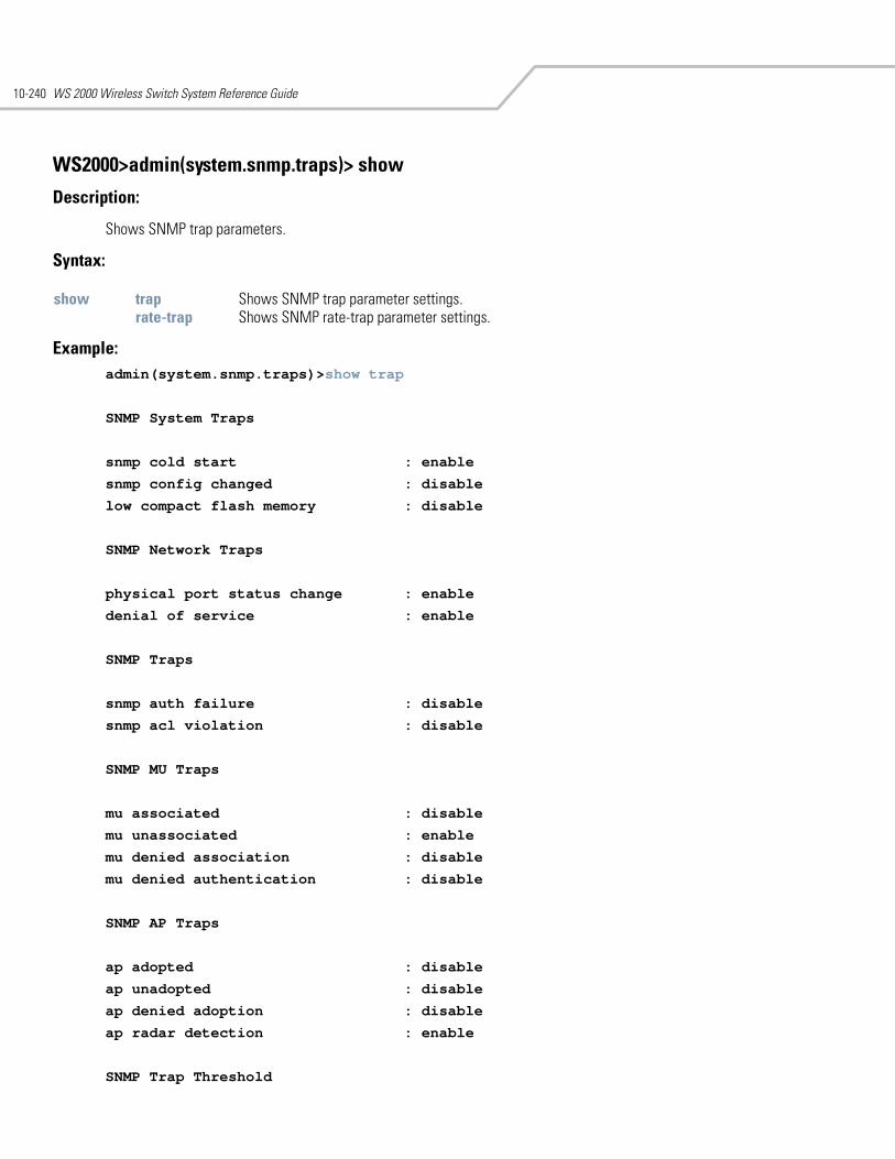
WS 2000 Wireless Switch System Reference Guide10-240
WS2000>admin(system.snmp.traps)> show
Description:
Shows SNMP trap parameters.
Syntax:
Example: admin(system.snmp.traps)>show trap
SNMP System Traps
snmp cold start : enable
snmp config changed : disable
low compact flash memory : disable
SNMP Network Traps
physical port status change : enable
denial of service : enable
SNMP Traps
snmp auth failure : disable
snmp acl violation : disable
SNMP MU Traps
mu associated : disable
mu unassociated : enable
mu denied association : disable
mu denied authentication : disable
SNMP AP Traps
ap adopted : disable
ap unadopted : disable
ap denied adoption : disable
ap radar detection : enable
SNMP Trap Threshold
show trap Shows SNMP trap parameter settings.rate-trap Shows SNMP rate-trap parameter settings.
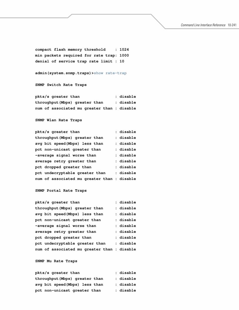
Command Line Interface Reference 10-241
compact flash memory threshold : 1024
min packets required for rate trap: 1000
denial of service trap rate limit : 10
admin(system.snmp.traps)>show rate-trap
SNMP Switch Rate Traps
pkts/s greater than : disable
throughput(Mbps) greater than : disable
num of associated mu greater than : disable
SNMP Wlan Rate Traps
pkts/s greater than : disable
throughput(Mbps) greater than : disable
avg bit speed(Mbps) less than : disable
pct non-unicast greater than : disable
-average signal worse than : disable
average retry greater than : disable
pct dropped greater than : disable
pct undecryptable greater than : disable
num of associated mu greater than : disable
SNMP Portal Rate Traps
pkts/s greater than : disable
throughput(Mbps) greater than : disable
avg bit speed(Mbps) less than : disable
pct non-unicast greater than : disable
-average signal worse than : disable
average retry greater than : disable
pct dropped greater than : disable
pct undecryptable greater than : disable
num of associated mu greater than : disable
SNMP Mu Rate Traps
pkts/s greater than : disable
throughput(Mbps) greater than : disable
avg bit speed(Mbps) less than : disable
pct non-unicast greater than : disable
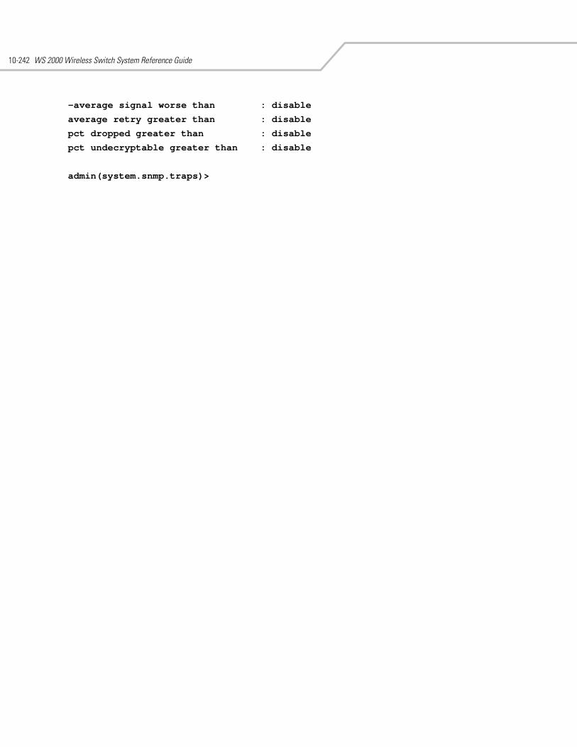
WS 2000 Wireless Switch System Reference Guide10-242
-average signal worse than : disable
average retry greater than : disable
pct dropped greater than : disable
pct undecryptable greater than : disable
admin(system.snmp.traps)>
Command Line Interface Reference 10-243
10.50 System SSH Commands
WS2000>admin(system)> ssh
Description:
Displays the secure shell (SSH) submenu. The items available under this command are shown below.
set Sets SSH parametersshow Shows SSH parameters. save Saves the configuration to system flash... Goes to the parent menu./ Goes to the root menu.
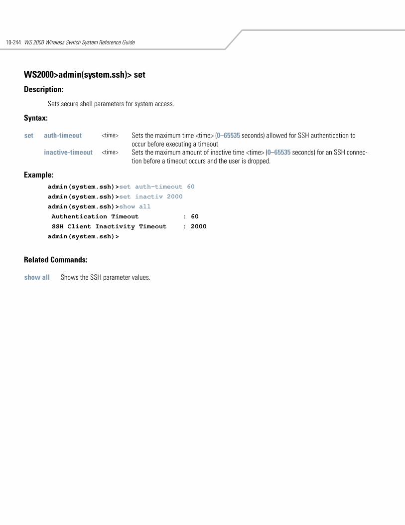
WS 2000 Wireless Switch System Reference Guide10-244
WS2000>admin(system.ssh)> set
Description:
Sets secure shell parameters for system access.
Syntax:
Example: admin(system.ssh)>set auth-timeout 60
admin(system.ssh)>set inactiv 2000
admin(system.ssh)>show all
Authentication Timeout : 60
SSH Client Inactivity Timeout : 2000
admin(system.ssh)>
Related Commands:
set auth-timeout <time> Sets the maximum time <time> (0–65535 seconds) allowed for SSH authentication to occur before executing a timeout.
inactive-timeout <time> Sets the maximum amount of inactive time <time> (0–65535 seconds) for an SSH connec-tion before a timeout occurs and the user is dropped.
show all Shows the SSH parameter values.
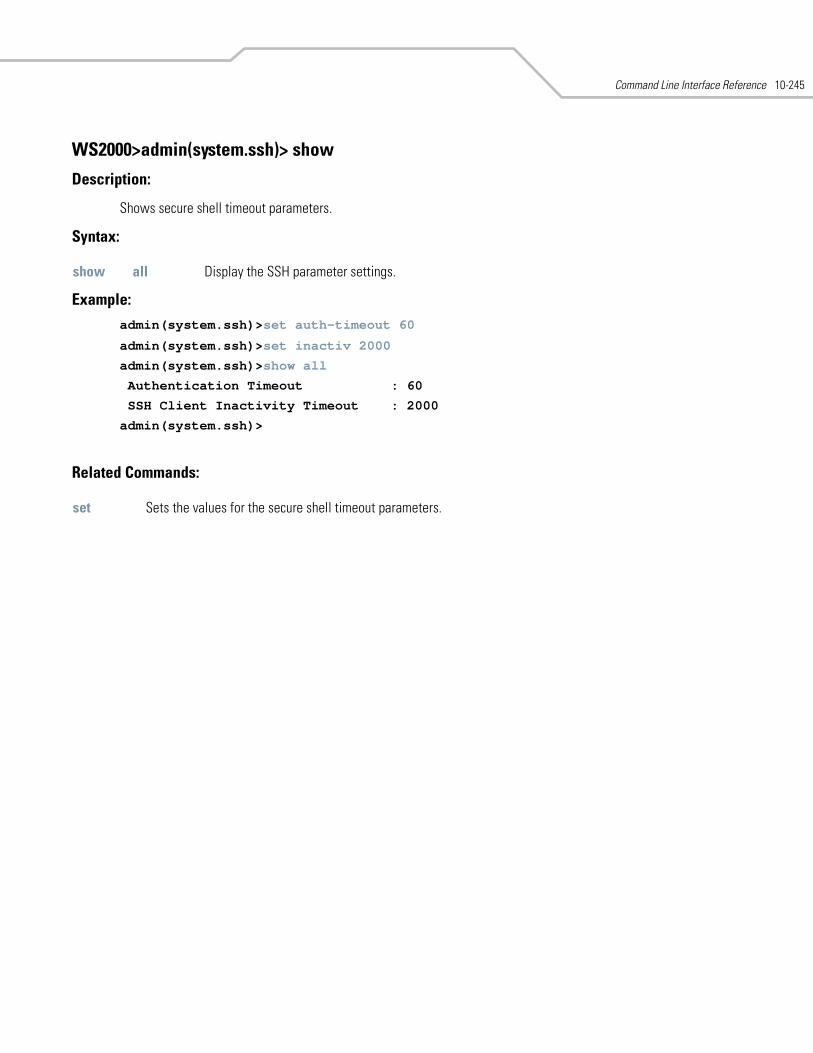
Command Line Interface Reference 10-245
WS2000>admin(system.ssh)> show
Description:
Shows secure shell timeout parameters.
Syntax:
Example: admin(system.ssh)>set auth-timeout 60
admin(system.ssh)>set inactiv 2000
admin(system.ssh)>show all
Authentication Timeout : 60
SSH Client Inactivity Timeout : 2000
admin(system.ssh)>
Related Commands:
show all Display the SSH parameter settings.
set Sets the values for the secure shell timeout parameters.

WS 2000 Wireless Switch System Reference Guide10-246
10.51 System User Database Commands
WS2000>admin(system)> userdb
Description:
Displays the userdb submenu. The items available under this command are shown below.
user Goes to the user submenu. group Goes to the group submenu. save Saves the configuration to system flash... Goes to the parent menu./ Goes to the root menu.
Command Line Interface Reference 10-247
10.52 System User Database Group Commands
WS2000>admin(system.userdb)> group
Description:
Displays the group submenu. The items available under this command are shown below.
create Creates a new group.delete Deletes a group.add Adds a user to a group. remove Removes a user from a group. show Shows the existing groups. save Saves the configuration to system flash... Goes to the parent menu./ Goes to the root menu.
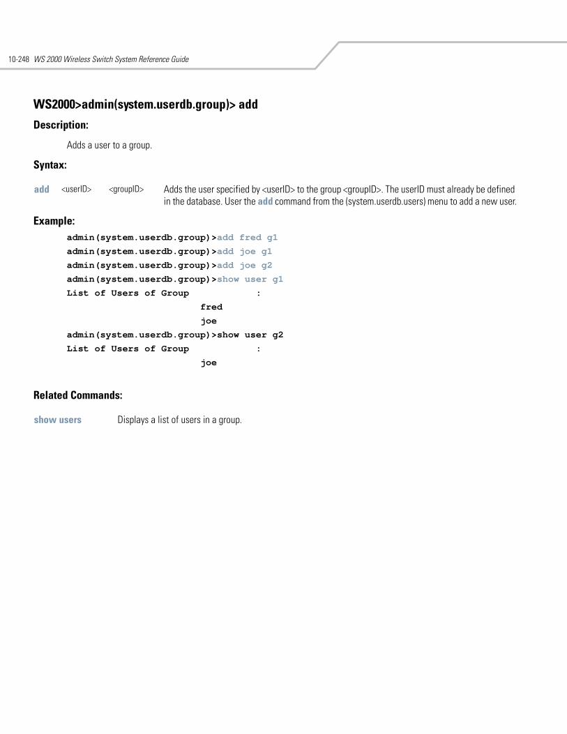
WS 2000 Wireless Switch System Reference Guide10-248
WS2000>admin(system.userdb.group)> add
Description:
Adds a user to a group.
Syntax:
Example: admin(system.userdb.group)>add fred g1
admin(system.userdb.group)>add joe g1
admin(system.userdb.group)>add joe g2
admin(system.userdb.group)>show user g1
List of Users of Group :
fred
joe
admin(system.userdb.group)>show user g2
List of Users of Group :
joe
Related Commands:
add <userID> <groupID> Adds the user specified by <userID> to the group <groupID>. The userID must already be defined in the database. User the add command from the (system.userdb.users) menu to add a new user.
show users Displays a list of users in a group.
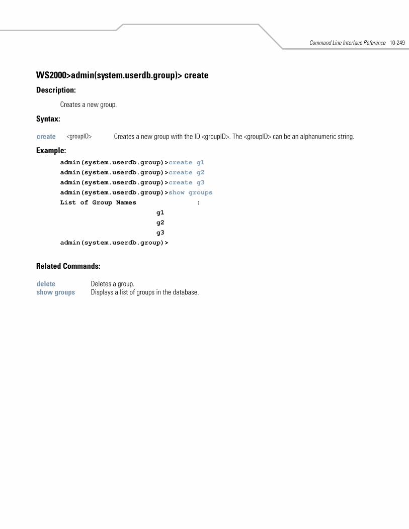
Command Line Interface Reference 10-249
WS2000>admin(system.userdb.group)> create
Description:
Creates a new group.
Syntax:
Example: admin(system.userdb.group)>create g1
admin(system.userdb.group)>create g2
admin(system.userdb.group)>create g3
admin(system.userdb.group)>show groups
List of Group Names :
g1
g2
g3
admin(system.userdb.group)>
Related Commands:
create <groupID> Creates a new group with the ID <groupID>. The <groupID> can be an alphanumeric string.
delete Deletes a group.show groups Displays a list of groups in the database.
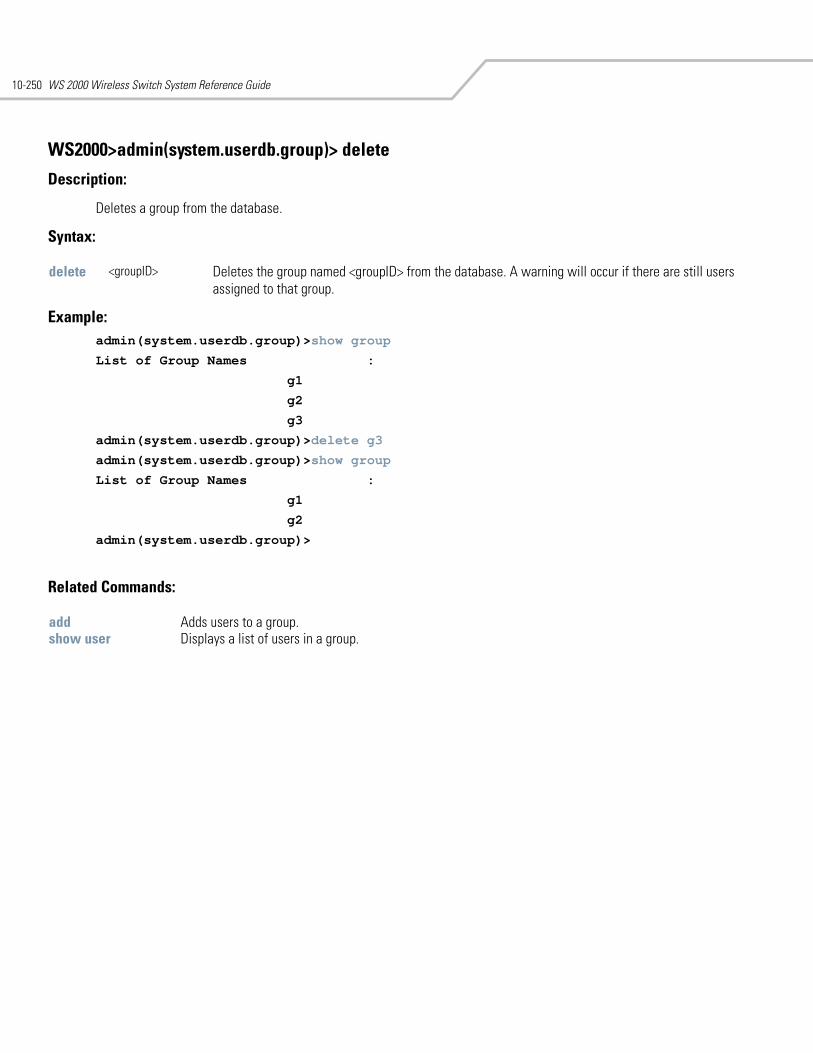
WS 2000 Wireless Switch System Reference Guide10-250
WS2000>admin(system.userdb.group)> delete
Description:
Deletes a group from the database.
Syntax:
Example: admin(system.userdb.group)>show group
List of Group Names :
g1
g2
g3
admin(system.userdb.group)>delete g3
admin(system.userdb.group)>show group
List of Group Names :
g1
g2
admin(system.userdb.group)>
Related Commands:
delete <groupID> Deletes the group named <groupID> from the database. A warning will occur if there are still users assigned to that group.
add Adds users to a group.show user Displays a list of users in a group.
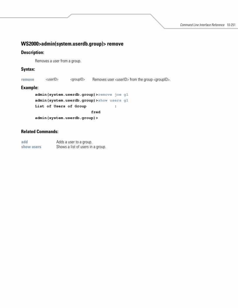
Command Line Interface Reference 10-251
WS2000>admin(system.userdb.group)> remove
Description:
Removes a user from a group.
Syntax:
Example: admin(system.userdb.group)>remove joe g1
admin(system.userdb.group)>show users g1
List of Users of Group :
fred
admin(system.userdb.group)>
Related Commands:
remove <userID> <groupID> Removes user <userID> from the group <groupID>.
add Adds a user to a group.show users Shows a list of users in a group.
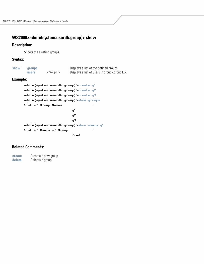
WS 2000 Wireless Switch System Reference Guide10-252
WS2000>admin(system.userdb.group)> show
Description:
Shows the existing groups.
Syntax:
Example: admin(system.userdb.group)>create g1
admin(system.userdb.group)>create g2
admin(system.userdb.group)>create g3
admin(system.userdb.group)>show groups
List of Group Names :
g1
g2
g3
admin(system.userdb.group)>show users g1
List of Users of Group :
fred
Related Commands:
show groups Displays a list of the defined groups.users <groupID> Displays a list of users in group <groupID>.
create Creates a new group.delete Deletes a group.
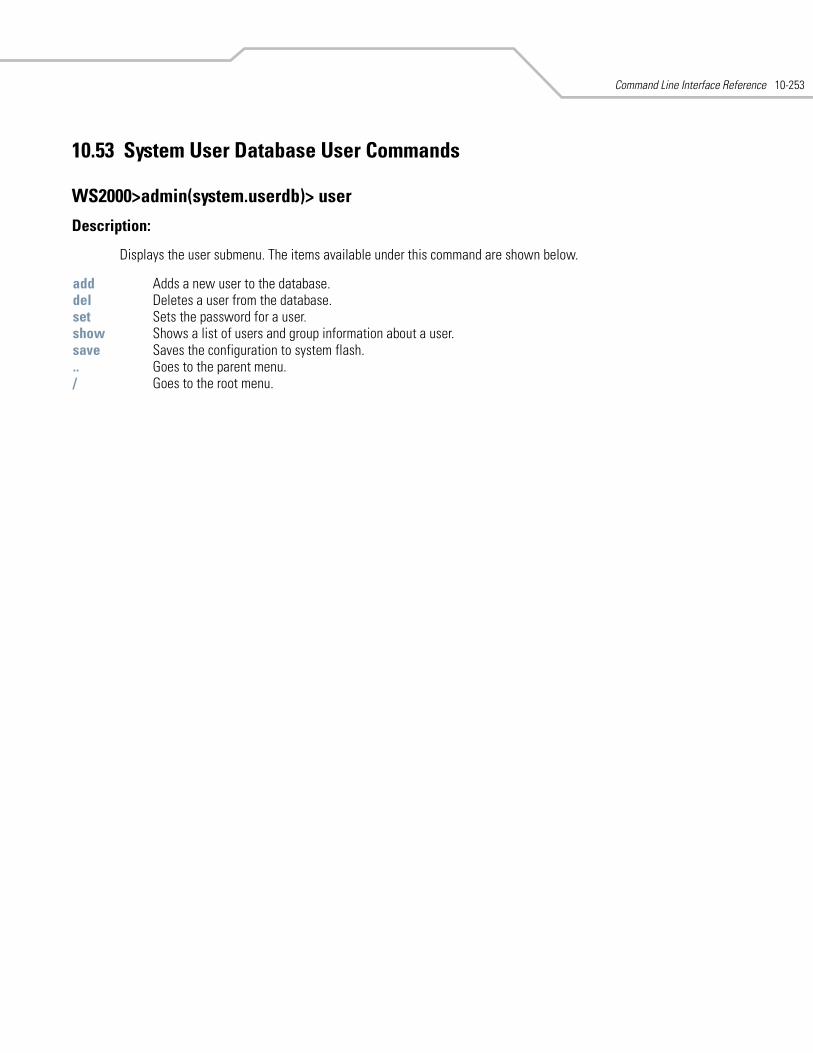
Command Line Interface Reference 10-253
10.53 System User Database User Commands
WS2000>admin(system.userdb)> user
Description:
Displays the user submenu. The items available under this command are shown below.
add Adds a new user to the database.del Deletes a user from the database. set Sets the password for a user.show Shows a list of users and group information about a user.save Saves the configuration to system flash... Goes to the parent menu./ Goes to the root menu.
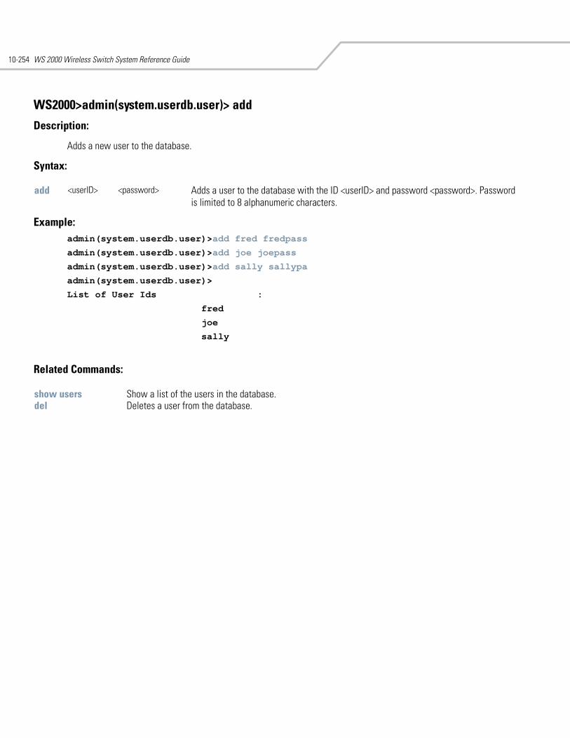
WS 2000 Wireless Switch System Reference Guide10-254
WS2000>admin(system.userdb.user)> add
Description:
Adds a new user to the database.
Syntax:
Example: admin(system.userdb.user)>add fred fredpass
admin(system.userdb.user)>add joe joepass
admin(system.userdb.user)>add sally sallypa
admin(system.userdb.user)>
List of User Ids :
fred
joe
sally
Related Commands:
add <userID> <password> Adds a user to the database with the ID <userID> and password <password>. Password is limited to 8 alphanumeric characters.
show users Show a list of the users in the database.del Deletes a user from the database.
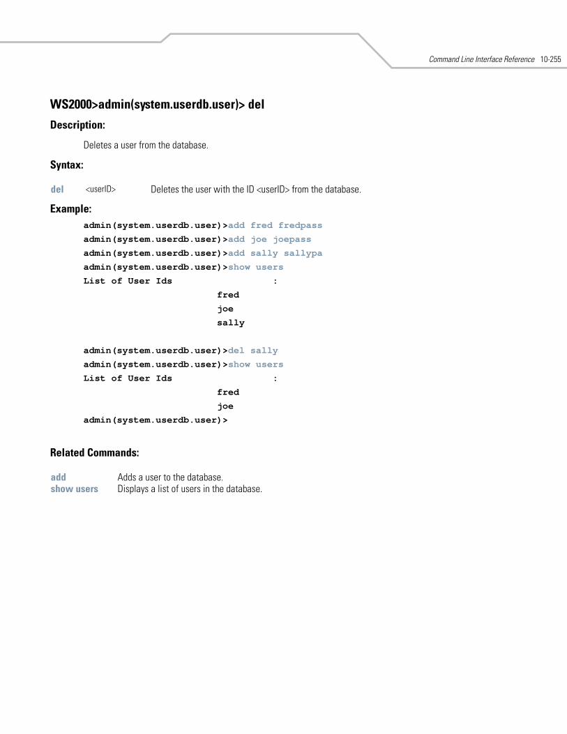
Command Line Interface Reference 10-255
WS2000>admin(system.userdb.user)> del
Description:
Deletes a user from the database.
Syntax:
Example: admin(system.userdb.user)>add fred fredpass
admin(system.userdb.user)>add joe joepass
admin(system.userdb.user)>add sally sallypa
admin(system.userdb.user)>show users
List of User Ids :
fred
joe
sally
admin(system.userdb.user)>del sally
admin(system.userdb.user)>show users
List of User Ids :
fred
joe
admin(system.userdb.user)>
Related Commands:
del <userID> Deletes the user with the ID <userID> from the database.
add Adds a user to the database.show users Displays a list of users in the database.
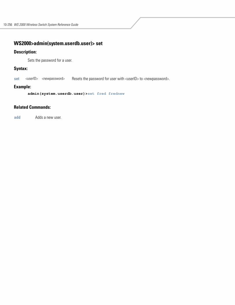
WS 2000 Wireless Switch System Reference Guide10-256
WS2000>admin(system.userdb.user)> set
Description:
Sets the password for a user.
Syntax:
Example: admin(system.userdb.user)>set fred frednew
Related Commands:
set <userID> <newpassword> Resets the password for user with <userID> to <newpassword>.
add Adds a new user.
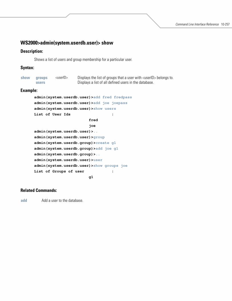
Command Line Interface Reference 10-257
WS2000>admin(system.userdb.user)> show
Description:
Shows a list of users and group membership for a particular user.
Syntax:
Example: admin(system.userdb.user)>add fred fredpass
admin(system.userdb.user)>add joe joepass
admin(system.userdb.user)>show users
List of User Ids :
fred
joe
admin(system.userdb.user)>..
admin(system.userdb.user)>group
admin(system.userdb.group)>create g1
admin(system.userdb.group)>add joe g1
admin(system.userdb.group)>..
admin(system.userdb.user)>user
admin(system.userdb.user)>show groups joe
List of Groups of user :
g1
Related Commands:
show groups <userID> Displays the list of groups that a user with <userID> belongs to.users Displays a list of all defined users in the database.
add Add a user to the database.
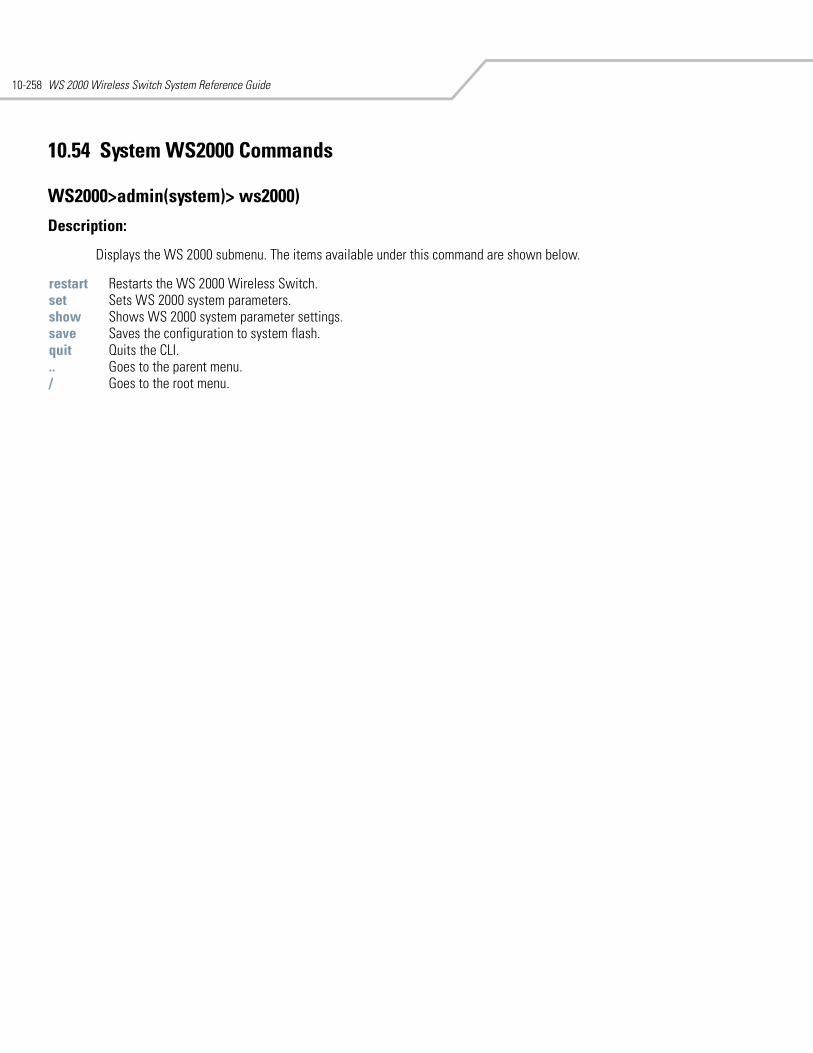
WS 2000 Wireless Switch System Reference Guide10-258
10.54 System WS2000 Commands
WS2000>admin(system)> ws2000)
Description:
Displays the WS 2000 submenu. The items available under this command are shown below.
restart Restarts the WS 2000 Wireless Switch. set Sets WS 2000 system parameters. show Shows WS 2000 system parameter settings. save Saves the configuration to system flash.quit Quits the CLI. .. Goes to the parent menu./ Goes to the root menu.
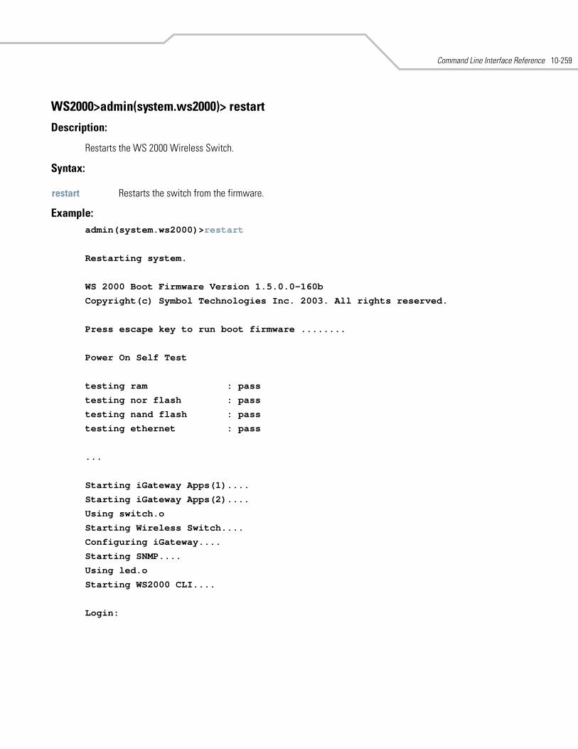
Command Line Interface Reference 10-259
WS2000>admin(system.ws2000)> restart
Description:
Restarts the WS 2000 Wireless Switch.
Syntax:
Example:admin(system.ws2000)>restart
Restarting system.
WS 2000 Boot Firmware Version 1.5.0.0-160b
Copyright(c) Symbol Technologies Inc. 2003. All rights reserved.
Press escape key to run boot firmware ........
Power On Self Test
testing ram : pass
testing nor flash : pass
testing nand flash : pass
testing ethernet : pass
...
Starting iGateway Apps(1)....
Starting iGateway Apps(2)....
Using switch.o
Starting Wireless Switch....
Configuring iGateway....
Starting SNMP....
Using led.o
Starting WS2000 CLI....
Login:
restart Restarts the switch from the firmware.

WS 2000 Wireless Switch System Reference Guide10-260
WS2000>admin(system.ws2000)> set
Description:
Sets WS 2000 system parameters.
Syntax:
Example: admin(system.ws2000)>show all
system name : Atlanta1
system location : Atlanta Field Office
admin email address : [email protected]
system uptime : 0 days 4 hours 33 minutes
WS2000 firmware version : 1.5.0.0-200b
country code : us
applet http access from lan : enable
applet http access from wan : disable
applet https access from lan : enable
applet https access from wan : disable
cli telnet access from lan : enable
cli telnet access from wan : disable
snmp access from lan : enable
snmp access from wan : enable
airbeam access mode : disable
airbeam access user name : airbeam
set airbeam mode enable/disable Enables/disables airbeam access.passwd <passwd> Sets the airbeam password to <passwd> (1–39 characters).
applet lan enable/disable Enables/disables http applet access from LAN. wan enable/disable Enables/disables http applet access from WAN. slan enable/disable Enables/disables https applet access from LAN. swan enable/disable Enables/disables https applet access from WAN.
cc <cc> Sets the WS2000 country code to two-letter <cc>.cli lan enable/disable Enables/disables CLI telnet access from LAN.
wan enable/disable Enables/disables CLI telnet access from WAN. email <email> Sets the WS2000 admin email address to <email> (1–59 characters). ftp lan enable/disable Enables/disables FTP access from the LAN.
wan enable/disable Enables/disables FTP access from the WAN.loc <loc> Sets the WS2000 system location to <loc> (1–59 characters). name <name> Sets the WS2000 system name to <name> (1–59 characters). ssh lan enable/disable Enables/disables secure shell access from the LAN.
wan enable/disable Enables/disables secure shell access from the WAN.snmp lan enable/disable Enables/disables SNMP access from LAN.
wan enable/disable Enables/disables SNMP access from WAN.timeout <time> Sets the idle timeout to <time> minutes (0–1440). Setting the value to 0
indicates not to timeout.
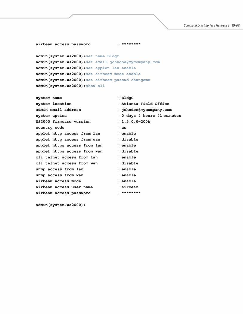
Command Line Interface Reference 10-261
airbeam access password : ********
admin(system.ws2000)>set name BldgC
admin(system.ws2000)>set email [email protected]
admin(system.ws2000)>set applet lan enable
admin(system.ws2000)>set airbeam mode enable
admin(system.ws2000)>set airbeam passwd changeme
admin(system.ws2000)>show all
system name : BldgC
system location : Atlanta Field Office
admin email address : [email protected]
system uptime : 0 days 4 hours 41 minutes
WS2000 firmware version : 1.5.0.0-200b
country code : us
applet http access from lan : enable
applet http access from wan : disable
applet https access from lan : enable
applet https access from wan : disable
cli telnet access from lan : enable
cli telnet access from wan : disable
snmp access from lan : enable
snmp access from wan : enable
airbeam access mode : enable
airbeam access user name : airbeam
airbeam access password : ********
admin(system.ws2000)>
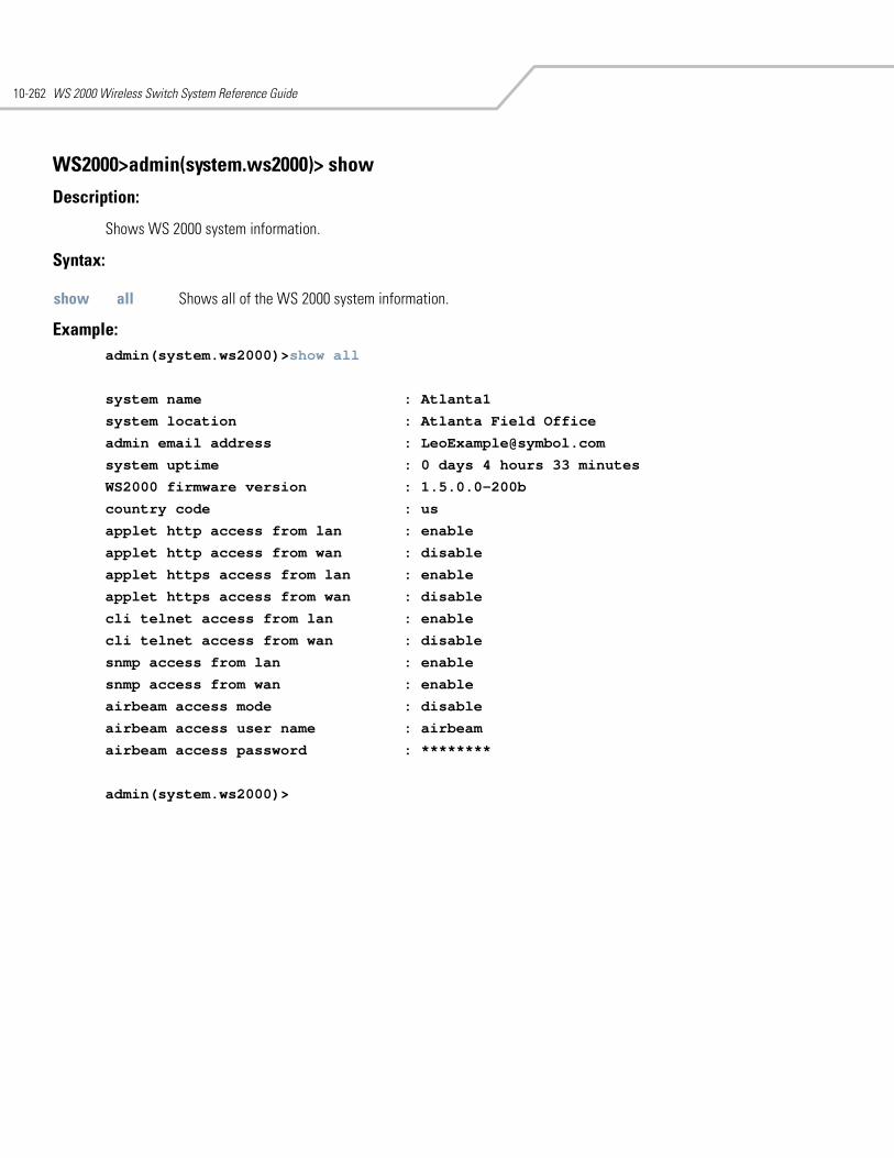
WS 2000 Wireless Switch System Reference Guide10-262
WS2000>admin(system.ws2000)> show
Description:
Shows WS 2000 system information.
Syntax:
Example: admin(system.ws2000)>show all
system name : Atlanta1
system location : Atlanta Field Office
admin email address : [email protected]
system uptime : 0 days 4 hours 33 minutes
WS2000 firmware version : 1.5.0.0-200b
country code : us
applet http access from lan : enable
applet http access from wan : disable
applet https access from lan : enable
applet https access from wan : disable
cli telnet access from lan : enable
cli telnet access from wan : disable
snmp access from lan : enable
snmp access from wan : enable
airbeam access mode : disable
airbeam access user name : airbeam
airbeam access password : ********
admin(system.ws2000)>
show all Shows all of the WS 2000 system information.
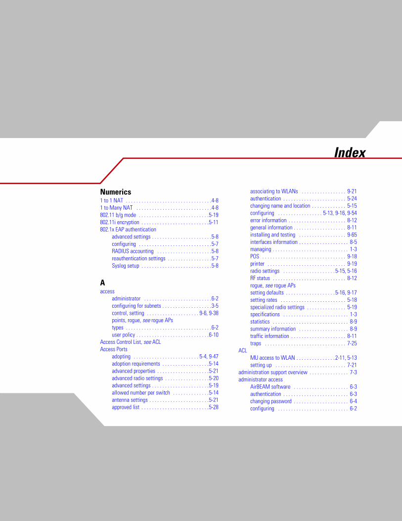
Index
Numerics1 to 1 NAT . . . . . . . . . . . . . . . . . . . . . . . . . . . . . . . . .4-81 to Many NAT . . . . . . . . . . . . . . . . . . . . . . . . . . . . .4-8802.11 b/g mode . . . . . . . . . . . . . . . . . . . . . . . . . . .5-19802.11i encryption . . . . . . . . . . . . . . . . . . . . . . . . . .5-11802.1x EAP authentication
advanced settings . . . . . . . . . . . . . . . . . . . . . . .5-8configuring . . . . . . . . . . . . . . . . . . . . . . . . . . . .5-7RADIUS accounting . . . . . . . . . . . . . . . . . . . . .5-8reauthentication settings . . . . . . . . . . . . . . . . .5-7Syslog setup . . . . . . . . . . . . . . . . . . . . . . . . . . .5-8
Aaccess
administrator . . . . . . . . . . . . . . . . . . . . . . . . . .6-2configuring for subnets . . . . . . . . . . . . . . . . . . .3-5control, setting . . . . . . . . . . . . . . . . . . . . 9-6, 9-38points, rogue, see rogue APstypes . . . . . . . . . . . . . . . . . . . . . . . . . . . . . . . . .6-2user policy . . . . . . . . . . . . . . . . . . . . . . . . . . . .6-10
Access Control List, see ACLAccess Ports
adopting . . . . . . . . . . . . . . . . . . . . . . . . . 5-4, 9-47adoption requirements . . . . . . . . . . . . . . . . . .5-14advanced properties . . . . . . . . . . . . . . . . . . . .5-21advanced radio settings . . . . . . . . . . . . . . . . .5-20advanced settings . . . . . . . . . . . . . . . . . . . . . .5-19allowed number per switch . . . . . . . . . . . . . .5-14antenna settings . . . . . . . . . . . . . . . . . . . . . . .5-21approved list . . . . . . . . . . . . . . . . . . . . . . . . . .5-28
associating to WLANs . . . . . . . . . . . . . . . . . 9-21authentication . . . . . . . . . . . . . . . . . . . . . . . . 5-24changing name and location . . . . . . . . . . . . . 5-15configuring . . . . . . . . . . . . . . . . . 5-13, 9-16, 9-54error information . . . . . . . . . . . . . . . . . . . . . . 8-12general information . . . . . . . . . . . . . . . . . . . . 8-11installing and testing . . . . . . . . . . . . . . . . . . 9-65interfaces information . . . . . . . . . . . . . . . . . . . 8-5managing . . . . . . . . . . . . . . . . . . . . . . . . . . . . . 1-3POS . . . . . . . . . . . . . . . . . . . . . . . . . . . . . . . . 9-18printer . . . . . . . . . . . . . . . . . . . . . . . . . . . . . . 9-19radio settings . . . . . . . . . . . . . . . . . . . . 5-15, 5-16RF status . . . . . . . . . . . . . . . . . . . . . . . . . . . . 8-12rogue, see rogue APssetting defaults . . . . . . . . . . . . . . . . . . . 5-16, 9-17setting rates . . . . . . . . . . . . . . . . . . . . . . . . . 5-18specialized radio settings . . . . . . . . . . . . . . . 5-19specifications . . . . . . . . . . . . . . . . . . . . . . . . . 1-3statistics . . . . . . . . . . . . . . . . . . . . . . . . . . . . . 8-9summary information . . . . . . . . . . . . . . . . . . . 8-9traffic information . . . . . . . . . . . . . . . . . . . . . 8-11traps . . . . . . . . . . . . . . . . . . . . . . . . . . . . . . . 7-25
ACLMU access to WLAN . . . . . . . . . . . . . . . 2-11, 5-13setting up . . . . . . . . . . . . . . . . . . . . . . . . . . . 7-21
administration support overview . . . . . . . . . . . . . . . 7-3administrator access
AirBEAM software . . . . . . . . . . . . . . . . . . . . . 6-3authentication . . . . . . . . . . . . . . . . . . . . . . . . . 6-3changing password . . . . . . . . . . . . . . . . . . . . . 6-4configuring . . . . . . . . . . . . . . . . . . . . . . . . . . . 6-2
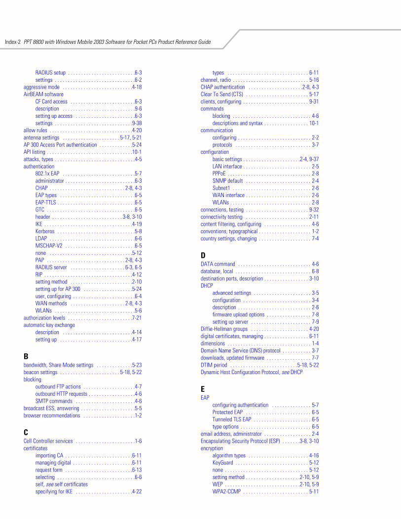
PPT 8800 with Windows Mobile 2003 Software for Pocket PCs Product Reference GuideIndex-2
RADIUS setup . . . . . . . . . . . . . . . . . . . . . . . . . .6-3settings . . . . . . . . . . . . . . . . . . . . . . . . . . . . . . .6-2
aggressive mode . . . . . . . . . . . . . . . . . . . . . . . . . . .4-18AirBEAM software
CF Card access . . . . . . . . . . . . . . . . . . . . . . . . .6-3description . . . . . . . . . . . . . . . . . . . . . . . . . . . .9-6setting up access . . . . . . . . . . . . . . . . . . . . . . .6-3settings . . . . . . . . . . . . . . . . . . . . . . . . . . . . . .9-38
allow rules . . . . . . . . . . . . . . . . . . . . . . . . . . . . . . . .4-20antenna settings . . . . . . . . . . . . . . . . . . . . . . 5-17, 5-21AP 300 Access Port authentication . . . . . . . . . . . . .5-24API listing . . . . . . . . . . . . . . . . . . . . . . . . . . . . . . . . .10-1attacks, types . . . . . . . . . . . . . . . . . . . . . . . . . . . . . . .4-5authentication
802.1x EAP . . . . . . . . . . . . . . . . . . . . . . . . . . . .5-7administrator . . . . . . . . . . . . . . . . . . . . . . . . . . .6-3CHAP . . . . . . . . . . . . . . . . . . . . . . . . . . . . . 2-8, 4-3EAP types . . . . . . . . . . . . . . . . . . . . . . . . . . . . .6-5EAP-TTLS . . . . . . . . . . . . . . . . . . . . . . . . . . . . . .6-5GTC . . . . . . . . . . . . . . . . . . . . . . . . . . . . . . . . . .6-5header . . . . . . . . . . . . . . . . . . . . . . . . . . . 3-8, 3-10IKE . . . . . . . . . . . . . . . . . . . . . . . . . . . . . . . . . .4-19Kerberos . . . . . . . . . . . . . . . . . . . . . . . . . . . . . .5-8LDAP . . . . . . . . . . . . . . . . . . . . . . . . . . . . . . . . .6-6MSCHAP-V2 . . . . . . . . . . . . . . . . . . . . . . . . . . .6-5none . . . . . . . . . . . . . . . . . . . . . . . . . . . . . . . .5-12PAP . . . . . . . . . . . . . . . . . . . . . . . . . . . . . . 2-8, 4-3RADIUS server . . . . . . . . . . . . . . . . . . . . . 6-3, 6-5RIP . . . . . . . . . . . . . . . . . . . . . . . . . . . . . . . . . .4-12setting method . . . . . . . . . . . . . . . . . . . . . . . .2-10setting up for AP 300 . . . . . . . . . . . . . . . . . . .5-24user, configuring . . . . . . . . . . . . . . . . . . . . . . . .6-4WAN methods . . . . . . . . . . . . . . . . . . . . . 2-8, 4-3WLANs . . . . . . . . . . . . . . . . . . . . . . . . . . . . . . .5-6
authorization levels . . . . . . . . . . . . . . . . . . . . . . . . .7-21automatic key exchange
description . . . . . . . . . . . . . . . . . . . . . . . . . . .4-14setting up . . . . . . . . . . . . . . . . . . . . . . . . . . . .4-17
Bbandwidth, Share Mode settings . . . . . . . . . . . . . .5-23beacon settings . . . . . . . . . . . . . . . . . . . . . . . 5-18, 5-22blocking
outbound FTP actions . . . . . . . . . . . . . . . . . . . .4-7outbound HTTP requests . . . . . . . . . . . . . . . . . .4-6SMTP commands . . . . . . . . . . . . . . . . . . . . . . .4-6
broadcast ESS, answering . . . . . . . . . . . . . . . . . . . . .5-5browser recommendations . . . . . . . . . . . . . . . . . . . .1-2
CCell Controller services . . . . . . . . . . . . . . . . . . . . . . .1-6certificates
importing CA . . . . . . . . . . . . . . . . . . . . . . . . . .6-11managing digital . . . . . . . . . . . . . . . . . . . . . . .6-11request form . . . . . . . . . . . . . . . . . . . . . . . . . .6-13selecting . . . . . . . . . . . . . . . . . . . . . . . . . . . . . .6-6self, see self certificatesspecifying for IKE . . . . . . . . . . . . . . . . . . . . . .4-22
types . . . . . . . . . . . . . . . . . . . . . . . . . . . . . . . 6-11channel, radio . . . . . . . . . . . . . . . . . . . . . . . . . . . . . 5-16CHAP authentication . . . . . . . . . . . . . . . . . . . . .2-8, 4-3Clear To Send (CTS) . . . . . . . . . . . . . . . . . . . . . . . . 5-17clients, configuring . . . . . . . . . . . . . . . . . . . . . . . . . 9-31commands
blocking . . . . . . . . . . . . . . . . . . . . . . . . . . . . . . 4-6descriptions and syntax . . . . . . . . . . . . . . . . . 10-1
communicationconfiguring . . . . . . . . . . . . . . . . . . . . . . . . . . . . 2-2protocols . . . . . . . . . . . . . . . . . . . . . . . . . . . . . 3-7
configurationbasic settings . . . . . . . . . . . . . . . . . . . . . .2-4, 9-37LAN interface . . . . . . . . . . . . . . . . . . . . . . . . . . 2-5PPPoE . . . . . . . . . . . . . . . . . . . . . . . . . . . . . . . . 2-8SNMP default . . . . . . . . . . . . . . . . . . . . . . . . . 2-4Subnet1 . . . . . . . . . . . . . . . . . . . . . . . . . . . . . . 2-6WAN interface . . . . . . . . . . . . . . . . . . . . . . . . . 2-6WLANs . . . . . . . . . . . . . . . . . . . . . . . . . . . . . . . 2-8
connections, testing . . . . . . . . . . . . . . . . . . . . . . . . 9-32connectivity testing . . . . . . . . . . . . . . . . . . . . . . . . 2-11content filtering, configuring . . . . . . . . . . . . . . . . . . 4-6conventions, typographical . . . . . . . . . . . . . . . . . . . . 1-2country settings, changing . . . . . . . . . . . . . . . . . . . . 7-4
DDATA command . . . . . . . . . . . . . . . . . . . . . . . . . . . . 4-6database, local . . . . . . . . . . . . . . . . . . . . . . . . . . . . . 6-8destination ports, description . . . . . . . . . . . . . . . . . 3-10DHCP
advanced settings . . . . . . . . . . . . . . . . . . . . . . 3-5configuration . . . . . . . . . . . . . . . . . . . . . . . . . . 3-4description . . . . . . . . . . . . . . . . . . . . . . . . . . . . 2-6firmware upload options . . . . . . . . . . . . . . . . . 7-8setting up server . . . . . . . . . . . . . . . . . . . . . . . 7-9
Diffie-Hellman groups . . . . . . . . . . . . . . . . . . . . . . 4-20digital certificates, managing . . . . . . . . . . . . . . . . . 6-11dimensions . . . . . . . . . . . . . . . . . . . . . . . . . . . . . . . . 1-4Domain Name Service (DNS) protocol . . . . . . . . . . . 3-7downloads, updated firmware . . . . . . . . . . . . . . . . . 7-7DTIM period . . . . . . . . . . . . . . . . . . . . . . . . . .5-18, 5-22Dynamic Host Configuration Protocol, see DHCP
EEAP
configuring authentication . . . . . . . . . . . . . . . 5-7Protected EAP . . . . . . . . . . . . . . . . . . . . . . . . . 6-5Tunneled TLS EAP . . . . . . . . . . . . . . . . . . . . . . 6-5type options . . . . . . . . . . . . . . . . . . . . . . . . . . . 6-5
email address, administrator . . . . . . . . . . . . . . . . . . 2-4Encapsulating Security Protocol (ESP) . . . . . . .3-8, 3-10encryption
algorithm types . . . . . . . . . . . . . . . . . . . . . . . 4-16KeyGuard . . . . . . . . . . . . . . . . . . . . . . . . . . . . 5-12none . . . . . . . . . . . . . . . . . . . . . . . . . . . . . . . . 5-12setting method . . . . . . . . . . . . . . . . . . . . .2-10, 5-9WEP . . . . . . . . . . . . . . . . . . . . . . . . . . . . .2-10, 5-9WPA2-CCMP . . . . . . . . . . . . . . . . . . . . . . . . . 5-11
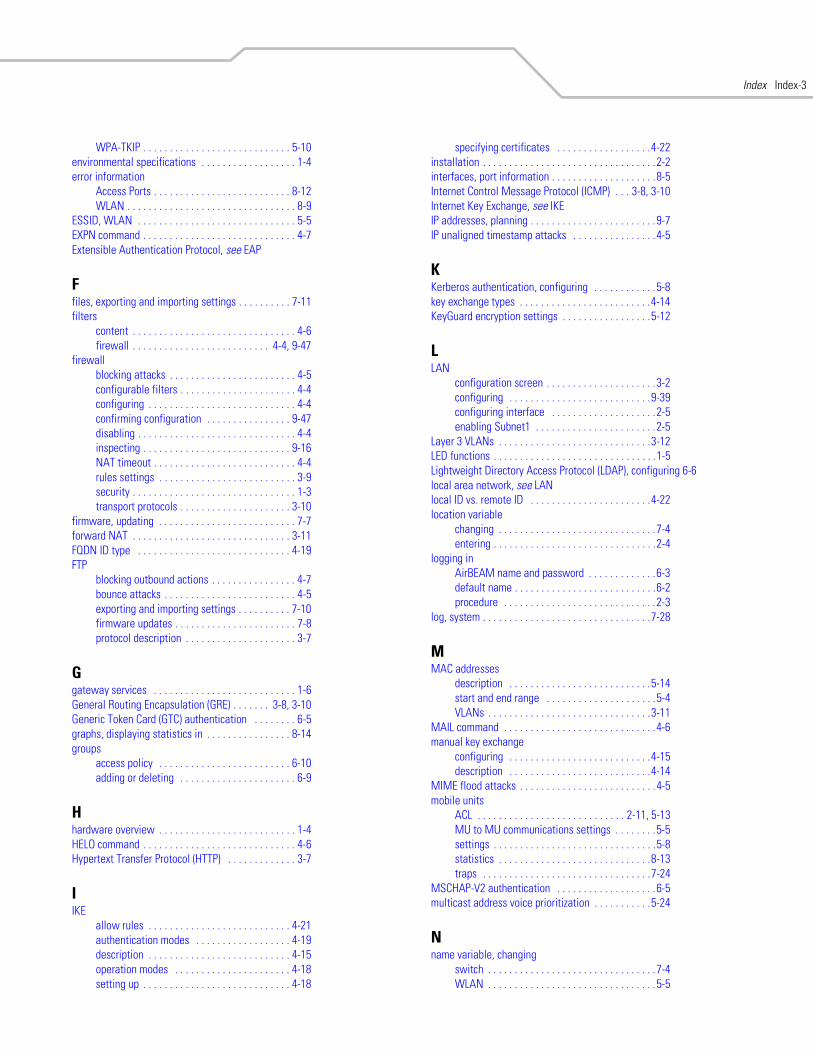
Index Index-3
WPA-TKIP . . . . . . . . . . . . . . . . . . . . . . . . . . . . 5-10environmental specifications . . . . . . . . . . . . . . . . . . 1-4error information
Access Ports . . . . . . . . . . . . . . . . . . . . . . . . . . 8-12WLAN . . . . . . . . . . . . . . . . . . . . . . . . . . . . . . . . 8-9
ESSID, WLAN . . . . . . . . . . . . . . . . . . . . . . . . . . . . . . 5-5EXPN command . . . . . . . . . . . . . . . . . . . . . . . . . . . . . 4-7Extensible Authentication Protocol, see EAP
Ffiles, exporting and importing settings . . . . . . . . . . 7-11filters
content . . . . . . . . . . . . . . . . . . . . . . . . . . . . . . . 4-6firewall . . . . . . . . . . . . . . . . . . . . . . . . . . 4-4, 9-47
firewallblocking attacks . . . . . . . . . . . . . . . . . . . . . . . . 4-5configurable filters . . . . . . . . . . . . . . . . . . . . . . 4-4configuring . . . . . . . . . . . . . . . . . . . . . . . . . . . . 4-4confirming configuration . . . . . . . . . . . . . . . . 9-47disabling . . . . . . . . . . . . . . . . . . . . . . . . . . . . . . 4-4inspecting . . . . . . . . . . . . . . . . . . . . . . . . . . . . 9-16NAT timeout . . . . . . . . . . . . . . . . . . . . . . . . . . . 4-4rules settings . . . . . . . . . . . . . . . . . . . . . . . . . . 3-9security . . . . . . . . . . . . . . . . . . . . . . . . . . . . . . . 1-3transport protocols . . . . . . . . . . . . . . . . . . . . . 3-10
firmware, updating . . . . . . . . . . . . . . . . . . . . . . . . . . 7-7forward NAT . . . . . . . . . . . . . . . . . . . . . . . . . . . . . . 3-11FQDN ID type . . . . . . . . . . . . . . . . . . . . . . . . . . . . . 4-19FTP
blocking outbound actions . . . . . . . . . . . . . . . . 4-7bounce attacks . . . . . . . . . . . . . . . . . . . . . . . . . 4-5exporting and importing settings . . . . . . . . . . 7-10firmware updates . . . . . . . . . . . . . . . . . . . . . . . 7-8protocol description . . . . . . . . . . . . . . . . . . . . . 3-7
Ggateway services . . . . . . . . . . . . . . . . . . . . . . . . . . . 1-6General Routing Encapsulation (GRE) . . . . . . . 3-8, 3-10Generic Token Card (GTC) authentication . . . . . . . . 6-5graphs, displaying statistics in . . . . . . . . . . . . . . . . 8-14groups
access policy . . . . . . . . . . . . . . . . . . . . . . . . . 6-10adding or deleting . . . . . . . . . . . . . . . . . . . . . . 6-9
Hhardware overview . . . . . . . . . . . . . . . . . . . . . . . . . . 1-4HELO command . . . . . . . . . . . . . . . . . . . . . . . . . . . . . 4-6Hypertext Transfer Protocol (HTTP) . . . . . . . . . . . . . 3-7
IIKE
allow rules . . . . . . . . . . . . . . . . . . . . . . . . . . . 4-21authentication modes . . . . . . . . . . . . . . . . . . 4-19description . . . . . . . . . . . . . . . . . . . . . . . . . . . 4-15operation modes . . . . . . . . . . . . . . . . . . . . . . 4-18setting up . . . . . . . . . . . . . . . . . . . . . . . . . . . . 4-18
specifying certificates . . . . . . . . . . . . . . . . . .4-22installation . . . . . . . . . . . . . . . . . . . . . . . . . . . . . . . . .2-2interfaces, port information . . . . . . . . . . . . . . . . . . . .8-5Internet Control Message Protocol (ICMP) . . . 3-8, 3-10Internet Key Exchange, see IKEIP addresses, planning . . . . . . . . . . . . . . . . . . . . . . . .9-7IP unaligned timestamp attacks . . . . . . . . . . . . . . . .4-5
KKerberos authentication, configuring . . . . . . . . . . . .5-8key exchange types . . . . . . . . . . . . . . . . . . . . . . . . .4-14KeyGuard encryption settings . . . . . . . . . . . . . . . . .5-12
LLAN
configuration screen . . . . . . . . . . . . . . . . . . . . .3-2configuring . . . . . . . . . . . . . . . . . . . . . . . . . . .9-39configuring interface . . . . . . . . . . . . . . . . . . . .2-5enabling Subnet1 . . . . . . . . . . . . . . . . . . . . . . .2-5
Layer 3 VLANs . . . . . . . . . . . . . . . . . . . . . . . . . . . . .3-12LED functions . . . . . . . . . . . . . . . . . . . . . . . . . . . . . . .1-5Lightweight Directory Access Protocol (LDAP), configuring 6-6local area network, see LANlocal ID vs. remote ID . . . . . . . . . . . . . . . . . . . . . . .4-22location variable
changing . . . . . . . . . . . . . . . . . . . . . . . . . . . . . .7-4entering . . . . . . . . . . . . . . . . . . . . . . . . . . . . . . .2-4
logging inAirBEAM name and password . . . . . . . . . . . . .6-3default name . . . . . . . . . . . . . . . . . . . . . . . . . . .6-2procedure . . . . . . . . . . . . . . . . . . . . . . . . . . . . .2-3
log, system . . . . . . . . . . . . . . . . . . . . . . . . . . . . . . . .7-28
MMAC addresses
description . . . . . . . . . . . . . . . . . . . . . . . . . . .5-14start and end range . . . . . . . . . . . . . . . . . . . . .5-4VLANs . . . . . . . . . . . . . . . . . . . . . . . . . . . . . . .3-11
MAIL command . . . . . . . . . . . . . . . . . . . . . . . . . . . . .4-6manual key exchange
configuring . . . . . . . . . . . . . . . . . . . . . . . . . . .4-15description . . . . . . . . . . . . . . . . . . . . . . . . . . .4-14
MIME flood attacks . . . . . . . . . . . . . . . . . . . . . . . . . .4-5mobile units
ACL . . . . . . . . . . . . . . . . . . . . . . . . . . . . 2-11, 5-13MU to MU communications settings . . . . . . . .5-5settings . . . . . . . . . . . . . . . . . . . . . . . . . . . . . . .5-8statistics . . . . . . . . . . . . . . . . . . . . . . . . . . . . .8-13traps . . . . . . . . . . . . . . . . . . . . . . . . . . . . . . . .7-24
MSCHAP-V2 authentication . . . . . . . . . . . . . . . . . . .6-5multicast address voice prioritization . . . . . . . . . . .5-24
Nname variable, changing
switch . . . . . . . . . . . . . . . . . . . . . . . . . . . . . . . .7-4WLAN . . . . . . . . . . . . . . . . . . . . . . . . . . . . . . . .5-5
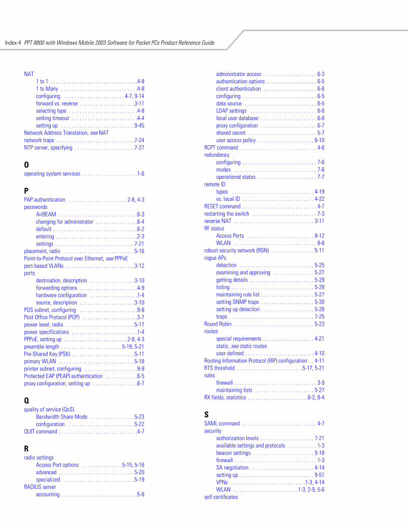
PPT 8800 with Windows Mobile 2003 Software for Pocket PCs Product Reference GuideIndex-4
NAT1 to 1 . . . . . . . . . . . . . . . . . . . . . . . . . . . . . . . . .4-81 to Many . . . . . . . . . . . . . . . . . . . . . . . . . . . . .4-8configuring . . . . . . . . . . . . . . . . . . . . . . . 4-7, 9-14forward vs. reverse . . . . . . . . . . . . . . . . . . . . .3-11selecting type . . . . . . . . . . . . . . . . . . . . . . . . . .4-8setting timeout . . . . . . . . . . . . . . . . . . . . . . . . .4-4setting up . . . . . . . . . . . . . . . . . . . . . . . . . . . .9-45
Network Address Translation, see NATnetwork traps . . . . . . . . . . . . . . . . . . . . . . . . . . . . . .7-24NTP server, specifying . . . . . . . . . . . . . . . . . . . . . . .7-27
Ooperating system services . . . . . . . . . . . . . . . . . . . . .1-6
PPAP authentication . . . . . . . . . . . . . . . . . . . . . . 2-8, 4-3passwords
AirBEAM . . . . . . . . . . . . . . . . . . . . . . . . . . . . . .6-3changing for administrator . . . . . . . . . . . . . . . .6-4default . . . . . . . . . . . . . . . . . . . . . . . . . . . . . . . .6-2entering . . . . . . . . . . . . . . . . . . . . . . . . . . . . . . .2-3settings . . . . . . . . . . . . . . . . . . . . . . . . . . . . . .7-21
placement, radio . . . . . . . . . . . . . . . . . . . . . . . . . . .5-16Point-to-Point Protocol over Ethernet, see PPPoEport-based VLANs . . . . . . . . . . . . . . . . . . . . . . . . . .3-12ports
destination, description . . . . . . . . . . . . . . . . .3-10forwarding options . . . . . . . . . . . . . . . . . . . . . .4-9hardware configuration . . . . . . . . . . . . . . . . . .1-4source, description . . . . . . . . . . . . . . . . . . . . .3-10
POS subnet, configuring . . . . . . . . . . . . . . . . . . . . . .9-8Post Office Protocol (POP) . . . . . . . . . . . . . . . . . . . . .3-7power level, radio . . . . . . . . . . . . . . . . . . . . . . . . . .5-17power specifications . . . . . . . . . . . . . . . . . . . . . . . . .1-4PPPoE, setting up . . . . . . . . . . . . . . . . . . . . . . . . 2-8, 4-3preamble length . . . . . . . . . . . . . . . . . . . . . . . 5-19, 5-21Pre-Shared Key (PSK) . . . . . . . . . . . . . . . . . . . . . . . .5-11primary WLAN . . . . . . . . . . . . . . . . . . . . . . . . . . . . .5-18printer subnet, configuring . . . . . . . . . . . . . . . . . . . .9-9Protected EAP (PEAP) authentication . . . . . . . . . . . .6-5proxy configuration, setting up . . . . . . . . . . . . . . . . .6-7
Qquality of service (QoS)
Bandwidth Share Mode . . . . . . . . . . . . . . . . .5-23configuration . . . . . . . . . . . . . . . . . . . . . . . . . .5-22
QUIT command . . . . . . . . . . . . . . . . . . . . . . . . . . . . . .4-7
Rradio settings
Access Port options . . . . . . . . . . . . . . . 5-15, 5-16advanced . . . . . . . . . . . . . . . . . . . . . . . . . . . . .5-20specialized . . . . . . . . . . . . . . . . . . . . . . . . . . .5-19
RADIUS serveraccounting . . . . . . . . . . . . . . . . . . . . . . . . . . . . .5-8
administrator access . . . . . . . . . . . . . . . . . . . . 6-3authentication options . . . . . . . . . . . . . . . . . . . 6-5client authentication . . . . . . . . . . . . . . . . . . . . 6-6configuring . . . . . . . . . . . . . . . . . . . . . . . . . . . . 6-5data source . . . . . . . . . . . . . . . . . . . . . . . . . . . 6-5LDAP settings . . . . . . . . . . . . . . . . . . . . . . . . . 6-6local user database . . . . . . . . . . . . . . . . . . . . . 6-8proxy configuration . . . . . . . . . . . . . . . . . . . . . 6-7shared secret . . . . . . . . . . . . . . . . . . . . . . . . . . 5-7user access policy . . . . . . . . . . . . . . . . . . . . . 6-10
RCPT command . . . . . . . . . . . . . . . . . . . . . . . . . . . . . 4-6redundancy
configuring . . . . . . . . . . . . . . . . . . . . . . . . . . . . 7-6modes . . . . . . . . . . . . . . . . . . . . . . . . . . . . . . . 7-6operational status . . . . . . . . . . . . . . . . . . . . . . 7-7
remote IDtypes . . . . . . . . . . . . . . . . . . . . . . . . . . . . . . . 4-19vs. local ID . . . . . . . . . . . . . . . . . . . . . . . . . . . 4-22
RESET command . . . . . . . . . . . . . . . . . . . . . . . . . . . . 4-7restarting the switch . . . . . . . . . . . . . . . . . . . . . . . . 7-3reverse NAT . . . . . . . . . . . . . . . . . . . . . . . . . . . . . . 3-11RF status
Access Ports . . . . . . . . . . . . . . . . . . . . . . . . . 8-12WLAN . . . . . . . . . . . . . . . . . . . . . . . . . . . . . . . 8-8
robust security network (RSN) . . . . . . . . . . . . . . . . 5-11rogue APs
detection . . . . . . . . . . . . . . . . . . . . . . . . . . . . 5-25examining and approving . . . . . . . . . . . . . . . 5-27getting details . . . . . . . . . . . . . . . . . . . . . . . . 5-29listing . . . . . . . . . . . . . . . . . . . . . . . . . . . . . . . 5-28maintaining rule list . . . . . . . . . . . . . . . . . . . . 5-27setting SNMP traps . . . . . . . . . . . . . . . . . . . . 5-30setting up detection . . . . . . . . . . . . . . . . . . . . 5-26traps . . . . . . . . . . . . . . . . . . . . . . . . . . . . . . . . 7-25
Round Robin . . . . . . . . . . . . . . . . . . . . . . . . . . . . . . 5-23routes
special requirements . . . . . . . . . . . . . . . . . . . 4-21static, see static routesuser-defined . . . . . . . . . . . . . . . . . . . . . . . . . . 4-10
Routing Information Protocol (RIP) configuration . . 4-11RTS threshold . . . . . . . . . . . . . . . . . . . . . . . . .5-17, 5-21rules
firewall . . . . . . . . . . . . . . . . . . . . . . . . . . . . . . . 3-9maintaining lists . . . . . . . . . . . . . . . . . . . . . . 5-27
RX fields, statistics . . . . . . . . . . . . . . . . . . . . . . .8-2, 8-4
SSAML command . . . . . . . . . . . . . . . . . . . . . . . . . . . . 4-7security
authorization levels . . . . . . . . . . . . . . . . . . . . 7-21available settings and protocols . . . . . . . . . . . 1-3beacon settings . . . . . . . . . . . . . . . . . . . . . . . 5-18firewall . . . . . . . . . . . . . . . . . . . . . . . . . . . . . . . 1-3SA negotiation . . . . . . . . . . . . . . . . . . . . . . . . 4-14setting up . . . . . . . . . . . . . . . . . . . . . . . . . . . . 9-51VPNs . . . . . . . . . . . . . . . . . . . . . . . . . . . .1-3, 4-14WLAN . . . . . . . . . . . . . . . . . . . . . . . . 1-3, 2-9, 5-6
self certificates
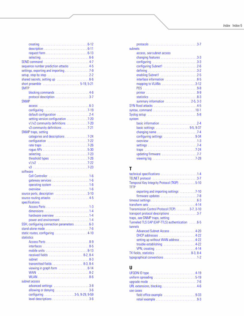
Index Index-5
creating . . . . . . . . . . . . . . . . . . . . . . . . . . . . . 6-12description . . . . . . . . . . . . . . . . . . . . . . . . . . . 6-11request form . . . . . . . . . . . . . . . . . . . . . . . . . . 6-13selecting . . . . . . . . . . . . . . . . . . . . . . . . . . . . . . 6-6
SEND command . . . . . . . . . . . . . . . . . . . . . . . . . . . . 4-7sequence number prediction attacks . . . . . . . . . . . . 4-5settings, exporting and importing . . . . . . . . . . . . . . . 7-9setup, step by step . . . . . . . . . . . . . . . . . . . . . . . . . . 2-2shared secrets, setting up . . . . . . . . . . . . . . . . . . . . 6-6short preamble . . . . . . . . . . . . . . . . . . . . . . . 5-19, 5-21SMTP
blocking commands . . . . . . . . . . . . . . . . . . . . . 4-6protocol description . . . . . . . . . . . . . . . . . . . . . 3-7
SNMPaccess . . . . . . . . . . . . . . . . . . . . . . . . . . . . . . . 6-3configuring . . . . . . . . . . . . . . . . . . . . . . . . . . . 7-19default configuration . . . . . . . . . . . . . . . . . . . . 2-4setting version configuration . . . . . . . . . . . . . 7-20v1/v2 community definitions . . . . . . . . . . . . . 7-20v3 community definitions . . . . . . . . . . . . . . . . 7-21
SNMP traps, settingcategories and descriptions . . . . . . . . . . . . . . 7-24configuration . . . . . . . . . . . . . . . . . . . . . . . . . 7-22rate traps . . . . . . . . . . . . . . . . . . . . . . . . . . . . 7-26rogue APs . . . . . . . . . . . . . . . . . . . . . . . . . . . . 5-30selecting . . . . . . . . . . . . . . . . . . . . . . . . . . . . . 7-23threshold types . . . . . . . . . . . . . . . . . . . . . . . 7-26v1/v2 . . . . . . . . . . . . . . . . . . . . . . . . . . . . . . . 7-22v3 . . . . . . . . . . . . . . . . . . . . . . . . . . . . . . . . . . 7-23
softwareCell Controller . . . . . . . . . . . . . . . . . . . . . . . . . 1-6gateway services . . . . . . . . . . . . . . . . . . . . . . . 1-6operating system . . . . . . . . . . . . . . . . . . . . . . . 1-6overview . . . . . . . . . . . . . . . . . . . . . . . . . . . . . . 1-6
source ports, description . . . . . . . . . . . . . . . . . . . . 3-10source routing attacks . . . . . . . . . . . . . . . . . . . . . . . 4-5specifications
Access Ports . . . . . . . . . . . . . . . . . . . . . . . . . . . 1-3dimensions . . . . . . . . . . . . . . . . . . . . . . . . . . . . 1-4hardware overview . . . . . . . . . . . . . . . . . . . . . 1-4power and environment . . . . . . . . . . . . . . . . . . 1-4
SSH, configuring connection parameters . . . . . . . . . 6-3stand-alone mode . . . . . . . . . . . . . . . . . . . . . . . . . . . 7-6static routes, configuring . . . . . . . . . . . . . . . . . . . . 4-10statistics
Access Ports . . . . . . . . . . . . . . . . . . . . . . . . . . . 8-9interfaces . . . . . . . . . . . . . . . . . . . . . . . . . . . . . 8-5mobile units . . . . . . . . . . . . . . . . . . . . . . . . . . 8-13received fields . . . . . . . . . . . . . . . . . . . . . 8-2, 8-4subnet . . . . . . . . . . . . . . . . . . . . . . . . . . . . . . . 8-3transmitted fields . . . . . . . . . . . . . . . . . . . 8-3, 8-4viewing in graph form . . . . . . . . . . . . . . . . . . 8-14WAN . . . . . . . . . . . . . . . . . . . . . . . . . . . . . . . . 8-2WLAN . . . . . . . . . . . . . . . . . . . . . . . . . . . . . . . . 8-6
subnet accessadvanced settings . . . . . . . . . . . . . . . . . . . . . . 3-8allowing or denying . . . . . . . . . . . . . . . . . . . . . 3-6configuring . . . . . . . . . . . . . . . . . . . 3-5, 9-29, 9-59level descriptions . . . . . . . . . . . . . . . . . . . . . . . 3-6
protocols . . . . . . . . . . . . . . . . . . . . . . . . . . . . . .3-7subnets
access, see subnet accesschanging features . . . . . . . . . . . . . . . . . . . . . . .3-3configuring . . . . . . . . . . . . . . . . . . . . . . . . . . . .3-3configuring Subnet1 . . . . . . . . . . . . . . . . . . . . .2-6defining . . . . . . . . . . . . . . . . . . . . . . . . . . . . . . .3-2enabling Subnet1 . . . . . . . . . . . . . . . . . . . . . . .2-5interface information . . . . . . . . . . . . . . . . . . . .8-5mapping to VLANs . . . . . . . . . . . . . . . . . . . . .3-12POS . . . . . . . . . . . . . . . . . . . . . . . . . . . . . . . . . .9-8printer . . . . . . . . . . . . . . . . . . . . . . . . . . . . . . . .9-9statistics . . . . . . . . . . . . . . . . . . . . . . . . . . . . . .8-3summary information . . . . . . . . . . . . . . . . 2-5, 3-3
SYN flood attacks . . . . . . . . . . . . . . . . . . . . . . . . . . .4-5syntax, command . . . . . . . . . . . . . . . . . . . . . . . . . . .10-1Syslog setup . . . . . . . . . . . . . . . . . . . . . . . . . . . . . . .5-8system
basic information . . . . . . . . . . . . . . . . . . . . . . .2-4basic settings . . . . . . . . . . . . . . . . . . . . . 9-5, 9-37changing name . . . . . . . . . . . . . . . . . . . . . . . . .7-4configuring settings . . . . . . . . . . . . . . . . . . . .9-34overview . . . . . . . . . . . . . . . . . . . . . . . . . . . . . .1-3settings . . . . . . . . . . . . . . . . . . . . . . . . . . . . . . .7-4traps . . . . . . . . . . . . . . . . . . . . . . . . . . . . . . . .7-24updating firmware . . . . . . . . . . . . . . . . . . . . . .7-7viewing log . . . . . . . . . . . . . . . . . . . . . . . . . . .7-28
Ttechnical specifications . . . . . . . . . . . . . . . . . . . . . . .1-4TELNET protocol . . . . . . . . . . . . . . . . . . . . . . . . . . . .3-7Temporal Key Integrity Protocol (TKIP) . . . . . . . . . .5-10TFTP
exporting and importing settings . . . . . . . . . .7-10firmware updates . . . . . . . . . . . . . . . . . . . . . . .7-8
timeout settings . . . . . . . . . . . . . . . . . . . . . . . . . . . . .6-3transform sets . . . . . . . . . . . . . . . . . . . . . . . . . . . . .4-14Transmission Control Protocol (TCP) . . . . . . . . 3-7, 3-10transport protocol descriptions . . . . . . . . . . . . . . . . .3-7traps, see SNMP traps, settingTunneled TLS EAP (EAP-TTLS) authentication . . . . .6-5tunnels
Advanced Subnet Access . . . . . . . . . . . . . . . .4-20DHCP addresses . . . . . . . . . . . . . . . . . . . . . . .4-22setting up without WAN address . . . . . . . . . .4-22trouble establishing . . . . . . . . . . . . . . . . . . . .4-22VPN, creating . . . . . . . . . . . . . . . . . . . . . . . . .4-14
TX fields, statistics . . . . . . . . . . . . . . . . . . . . . . 8-3, 8-4typographical conventions . . . . . . . . . . . . . . . . . . . . .1-2
UUFQDN ID type . . . . . . . . . . . . . . . . . . . . . . . . . . . . .4-19uniform spreading . . . . . . . . . . . . . . . . . . . . . . . . . .5-19upgrade mode . . . . . . . . . . . . . . . . . . . . . . . . . . . . . .7-6URL extensions, blocking . . . . . . . . . . . . . . . . . . . . . .4-6use cases
field office example . . . . . . . . . . . . . . . . . . . .9-33retail example . . . . . . . . . . . . . . . . . . . . . . . . . .9-3
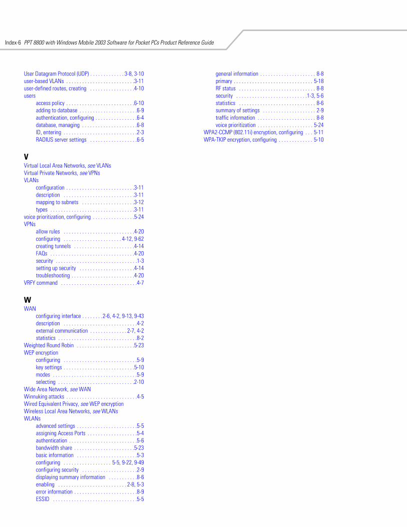
PPT 8800 with Windows Mobile 2003 Software for Pocket PCs Product Reference GuideIndex-6
User Datagram Protocol (UDP) . . . . . . . . . . . . . 3-8, 3-10user-based VLANs . . . . . . . . . . . . . . . . . . . . . . . . . .3-11user-defined routes, creating . . . . . . . . . . . . . . . . .4-10users
access policy . . . . . . . . . . . . . . . . . . . . . . . . . .6-10adding to database . . . . . . . . . . . . . . . . . . . . . .6-9authentication, configuring . . . . . . . . . . . . . . . .6-4database, managing . . . . . . . . . . . . . . . . . . . . .6-8ID, entering . . . . . . . . . . . . . . . . . . . . . . . . . . . .2-3RADIUS server settings . . . . . . . . . . . . . . . . . .6-5
VVirtual Local Area Networks, see VLANsVirtual Private Networks, see VPNsVLANs
configuration . . . . . . . . . . . . . . . . . . . . . . . . . .3-11description . . . . . . . . . . . . . . . . . . . . . . . . . . .3-11mapping to subnets . . . . . . . . . . . . . . . . . . . .3-12types . . . . . . . . . . . . . . . . . . . . . . . . . . . . . . . .3-11
voice prioritization, configuring . . . . . . . . . . . . . . . .5-24VPNs
allow rules . . . . . . . . . . . . . . . . . . . . . . . . . . .4-20configuring . . . . . . . . . . . . . . . . . . . . . . 4-12, 9-62creating tunnels . . . . . . . . . . . . . . . . . . . . . . .4-14FAQs . . . . . . . . . . . . . . . . . . . . . . . . . . . . . . . .4-20security . . . . . . . . . . . . . . . . . . . . . . . . . . . . . . .1-3setting up security . . . . . . . . . . . . . . . . . . . . .4-14troubleshooting . . . . . . . . . . . . . . . . . . . . . . . .4-20
VRFY command . . . . . . . . . . . . . . . . . . . . . . . . . . . . .4-7
WWAN
configuring interface . . . . . . . .2-6, 4-2, 9-13, 9-43description . . . . . . . . . . . . . . . . . . . . . . . . . . . .4-2external communication . . . . . . . . . . . . . . 2-7, 4-2statistics . . . . . . . . . . . . . . . . . . . . . . . . . . . . . .8-2
Weighted Round Robin . . . . . . . . . . . . . . . . . . . . . .5-23WEP encryption
configuring . . . . . . . . . . . . . . . . . . . . . . . . . . . .5-9key settings . . . . . . . . . . . . . . . . . . . . . . . . . . .5-10modes . . . . . . . . . . . . . . . . . . . . . . . . . . . . . . . .5-9selecting . . . . . . . . . . . . . . . . . . . . . . . . . . . . .2-10
Wide Area Network, see WANWinnuking attacks . . . . . . . . . . . . . . . . . . . . . . . . . . .4-5Wired Equivalent Privacy, see WEP encryptionWireless Local Area Networks, see WLANsWLANs
advanced settings . . . . . . . . . . . . . . . . . . . . . . .5-5assigning Access Ports . . . . . . . . . . . . . . . . . . .5-4authentication . . . . . . . . . . . . . . . . . . . . . . . . . .5-6bandwidth share . . . . . . . . . . . . . . . . . . . . . . .5-23basic information . . . . . . . . . . . . . . . . . . . . . . .5-3configuring . . . . . . . . . . . . . . . . . . 5-5, 9-22, 9-49configuring security . . . . . . . . . . . . . . . . . . . . .2-9displaying summary information . . . . . . . . . . .8-6enabling . . . . . . . . . . . . . . . . . . . . . . . . . . 2-8, 5-3error information . . . . . . . . . . . . . . . . . . . . . . . .8-9ESSID . . . . . . . . . . . . . . . . . . . . . . . . . . . . . . . .5-5
general information . . . . . . . . . . . . . . . . . . . . . 8-8primary . . . . . . . . . . . . . . . . . . . . . . . . . . . . . . 5-18RF status . . . . . . . . . . . . . . . . . . . . . . . . . . . . . 8-8security . . . . . . . . . . . . . . . . . . . . . . . . . . .1-3, 5-6statistics . . . . . . . . . . . . . . . . . . . . . . . . . . . . . 8-6summary of settings . . . . . . . . . . . . . . . . . . . . 2-9traffic information . . . . . . . . . . . . . . . . . . . . . . 8-8voice prioritization . . . . . . . . . . . . . . . . . . . . . 5-24
WPA2-CCMP (802.11i) encryption, configuring . . . 5-11WPA-TKIP encryption, configuring . . . . . . . . . . . . . 5-10


72E-72622-01 Rev A June 2005
Symbol Technologies, Inc.One Symbol PlazaHoltsville, New York 11742-1300http://www.symbol.com