Wrinkling of Foils - - HOME
48
Wrinkling of Foils Timothy J. Walker - TJWalker + Associates, Inc. 164 Stonebridge Road, Saint Paul, MN 55118 USA 651-686-5400, [email protected], www.webhandling.com Copyright TJWalker and Associates, Inc 2011 1
Transcript of Wrinkling of Foils - - HOME
Wrinkling of Foils
Timothy J. Walker - TJWalker + Associates, Inc. 164 Stonebridge Road, Saint Paul, MN 55118 USA
651-686-5400, [email protected], www.webhandling.com
Copyright TJWalker and Associates, Inc 2011 1
Questions
Will foils run wrinkle-free on equipment designed for paper and film handling?
Are foils more sensitive than films to specific wrinkle causes?
What best practices will allow running thin, wide foils without wrinkles?
Copyright TJWalker and Associates, Inc 2011 2
Aluminum Foil vs. Polyester Film
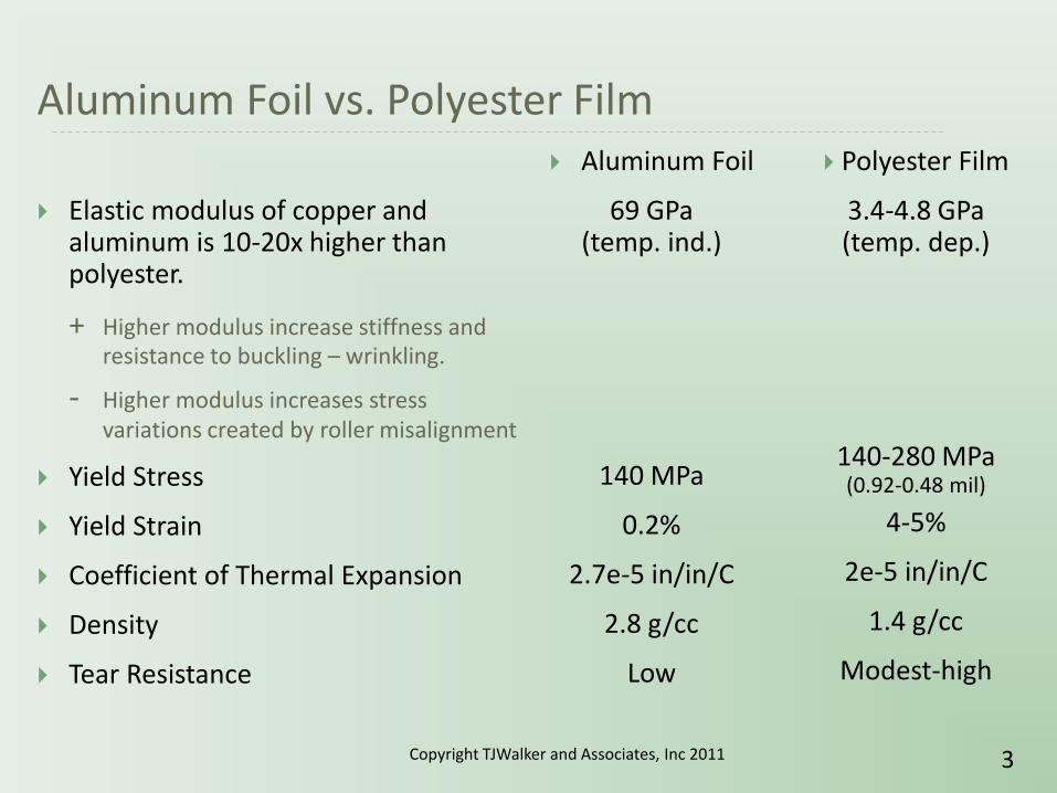
Elastic modulus of copper and aluminum is 10-20x higher than polyester.
+ Higher modulus increase stiffness and resistance to buckling – wrinkling.
- Higher modulus increases stress variations created by roller misalignment
Yield Stress
Yield Strain
Coefficient of Thermal Expansion
Density
Tear Resistance
Aluminum Foil
69 GPa (temp. ind.)
140 MPa
0.2%
2.7e-5 in/in/C
2.8 g/cc
Low
Polyester Film
3.4-4.8 GPa (temp. dep.)
140-280 MPa (0.92-0.48 mil)
4-5%
2e-5 in/in/C
1.4 g/cc
Modest-high
Copyright TJWalker and Associates, Inc 2011 3

Aluminum Foil vs. Polyester Film
Elastic modulus of copper and aluminum is 10-20x higher than polyester.
+ Higher modulus increase stiffness and resistance to buckling – wrinkling.
- Higher modulus increases stress variations created by roller misalignment
Yield Stress
Yield Strain
Coefficient of Thermal Expansion
Density
Tear Resistance
Aluminum Foil
10 Mpsi (temp. ind.)
21 kpsi
0.2%
13e-6 in/in/F
0.0975 lb/in^3
Low
Polyester Film
0.5-0.7 Mpsi (temp. dep.)
21-41 kpsi (0.92-0.48 mil)
4-5%
9e-6 in/in/F
0.047 lb/in^3
Modest-high
Copyright TJWalker and Associates, Inc 2011 4

Detail on typical strain
For a typical tension of 175 N/m per 25 microns (6.9 MPa)* the strain of aluminum and polyester will be:
Strain (Al) = 0.0001 = 0.01%
Strain (PET) = 0.002 = 0.2%
Conclusion: Typical strains of Al foils are 20X lower than PET.
* 1 PLI per mil (1000 psi)
Copyright TJWalker and Associates, Inc 2011 5

Shear Wrinkles Contour Plot Regimes
Wrinkling
Troughing
Regime I Buckle-Free
Regime II Wrinkle-Free
Copyright TJWalker and Associates, Inc 2011 6
Roller misalignment is a well understood wrinkle mechanism, typically documented in tension-roller angle contour plots.
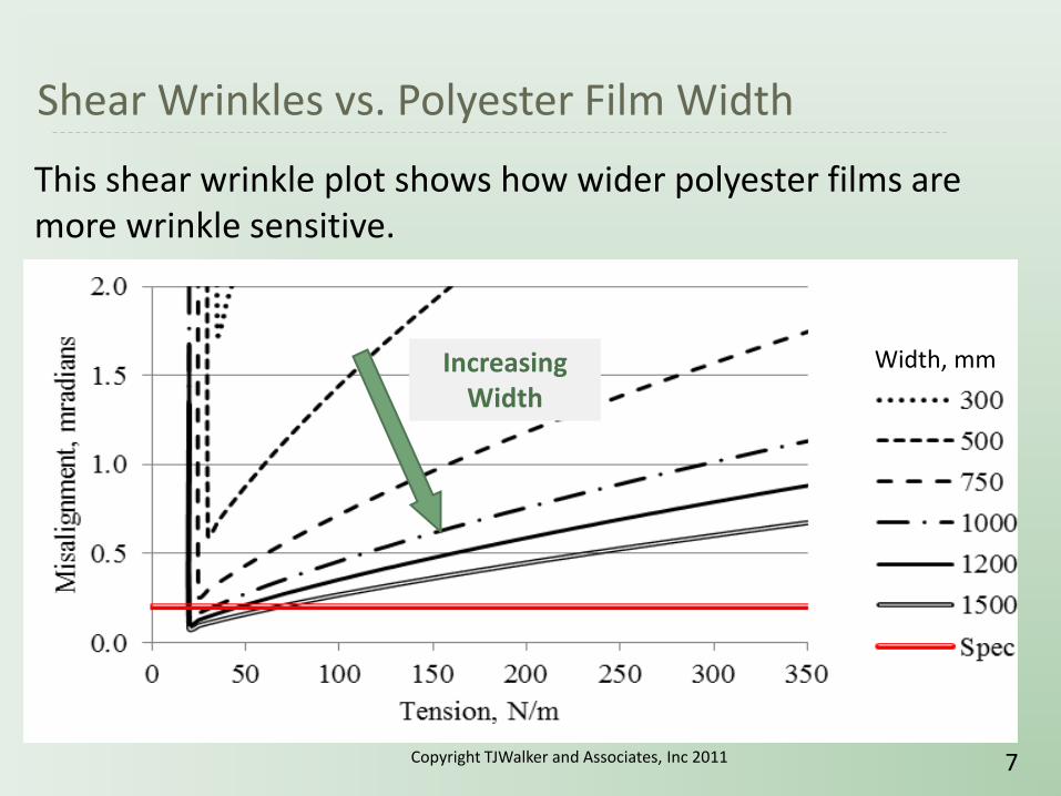
Shear Wrinkles vs. Polyester Film Width
Width, mm Increasing Width
Copyright TJWalker and Associates, Inc 2011 7
This shear wrinkle plot shows how wider polyester films are more wrinkle sensitive.

Shear Wrinkles – Aluminum vs. Polyester as a Function of Tension
Decreasing Thickness
0.2 mradians
Copyright TJWalker and Associates, Inc 2011 8
This shear wrinkle plot shows how thickness has a more dramatic effect on wrinkle-free foil handling for a given width.

Shear Wrinkles vs. Foil Width
Wide foils look like a web handling nightmare.
Copyright TJWalker and Associates, Inc 2011 9
Models predict that foils are especially sensitive to misalignment at greater widths.
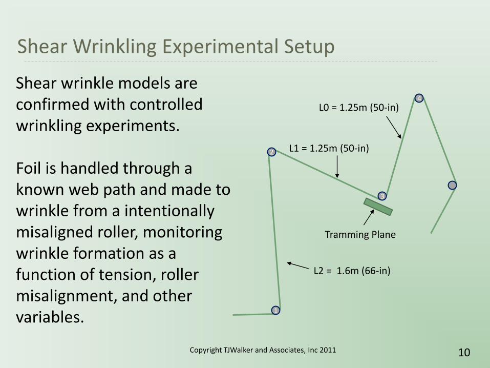
Shear Wrinkling Experimental Setup
1
2
3
4
L1 = 1.25m (50-in)
L2 = 1.6m (66-in)
L0 = 1.25m (50-in)
Tramming Plane
Copyright TJWalker and Associates, Inc 2011 10
Shear wrinkle models are confirmed with controlled wrinkling experiments. Foil is handled through a known web path and made to wrinkle from a intentionally misaligned roller, monitoring wrinkle formation as a function of tension, roller misalignment, and other variables.

Shear Wrinkle Experimental Setup
Pivoting Plane
Copyright TJWalker and Associates, Inc 2011 11
1
2
3
4
Tramming Plane

Shear Wrinkling in Wide Al and Cu Foils – Results vs. Theory
Al: 20 micron, 1.2m Cu: 12 micron, 1.2m At 40 & 80 N/m,
Al would NOT wrinkle.
Copyright TJWalker and Associates, Inc 2011 12
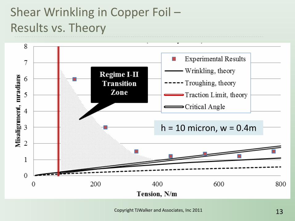
Shear Wrinkling in Copper Foil – Results vs. Theory
h = 10 micron, w = 0.4m
Copyright TJWalker and Associates, Inc 2011 13
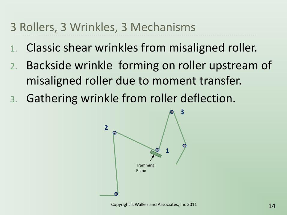
3 Rollers, 3 Wrinkles, 3 Mechanisms
1. Classic shear wrinkles from misaligned roller.
2. Backside wrinkle forming on roller upstream of misaligned roller due to moment transfer.
3. Gathering wrinkle from roller deflection.
1
2
3
4
Tramming Plane
2
1
3
Copyright TJWalker and Associates, Inc 2011 14
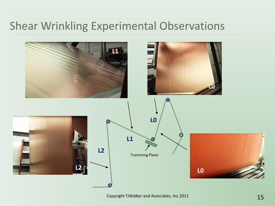
Shear Wrinkling Experimental Observations
L2
L1
L0
L0
1
2
3
4
Tramming Plane L2
L1
L0
Copyright TJWalker and Associates, Inc 2011 15
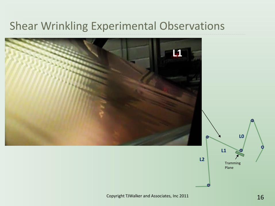
Shear Wrinkling Experimental Observations
L1
1
2
3
4
Tramming Plane
L2
L1
L0
Copyright TJWalker and Associates, Inc 2011 16

Shear Wrinkling Experimental Observations
1
2
3
4
Tramming Plane
L2
L1
L0
L2
Copyright TJWalker and Associates, Inc 2011 17

Shear Wrinkling Experimental Observations
L0
1
2
3
4
Tramming Plane
L2
L1
L0
L0
Classic shear wrinkles from
misaligned roller.
Copyright TJWalker and Associates, Inc 2011 18
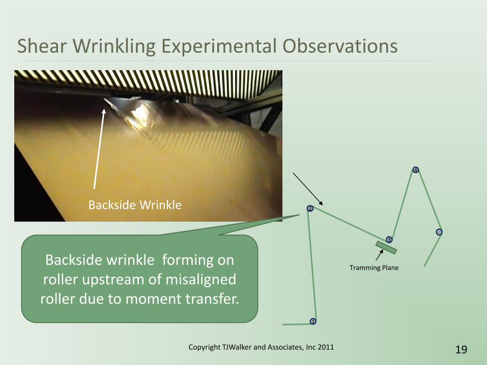
Shear Wrinkling Experimental Observations
1
2
3
4
Tramming Plane
Backside Wrinkle
Backside wrinkle forming on roller upstream of misaligned roller due to moment transfer.
Copyright TJWalker and Associates, Inc 2011 19

Slack Edge Condition
There will be a slack edge here if: 𝜃𝑤 > 𝐿𝜀
L
q = angle of misalignment (radians)
w = width (in.)
L = span length (in.)
e = average strain (dimensionless)
Copyright TJWalker and Associates, Inc 2011 20
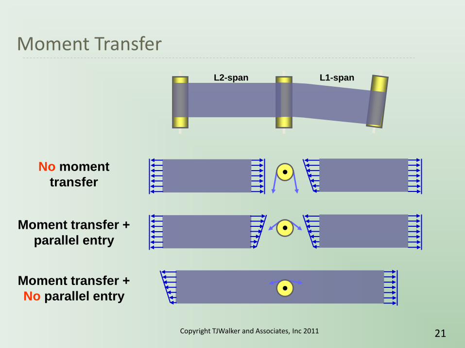
Moment Transfer
L1-span L2-span
No moment
transfer
Moment transfer +
parallel entry
Moment transfer +
No parallel entry
Copyright TJWalker and Associates, Inc 2011 21

Moment Transfer and Negative Steering
Moment transfer and L2>L1 can lead to negative steering.
Steering
Roller (SR)
Upstream
Roller (UR)
Case 2: Moment Transfer on UR
(negative steering in
L2-span)
Case 3: Low Traction on UR
(effective steering
span increases)
Case 1: High Traction on UR
(all bending in L1-span)
L1-span L2-span
Copyright TJWalker and Associates, Inc 2011 22

Moment Transfer and Backside Shear Wrinkles
Steering
Roller (SR)
Upstream
Roller (UR)
Case 2: Moment Transfer on UR
(negative steering in
L2-span)
L1-span L2-span
Direction of web shift
Direction of walking
wrinkles
Copyright TJWalker and Associates, Inc 2011 23

Shear Wrinkling Experimental Observations
1
2
3
4
Tramming Plane
Stationary Downstream
Wrinkle
Gathering wrinkle from roller deflection.
Copyright TJWalker and Associates, Inc 2011 24
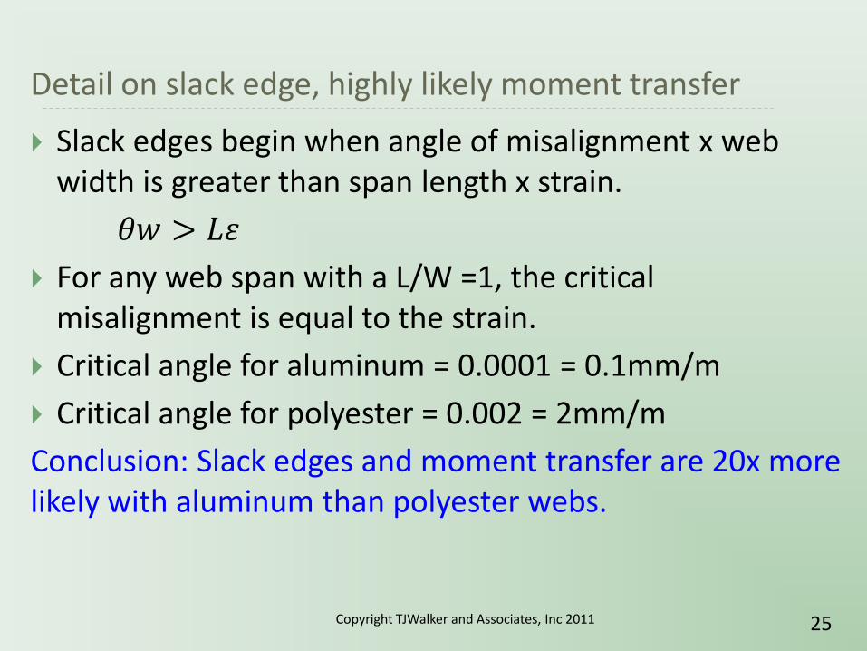
Detail on slack edge, highly likely moment transfer
Slack edges begin when angle of misalignment x web width is greater than span length x strain.
𝜃𝑤 > 𝐿𝜀
For any web span with a L/W =1, the critical misalignment is equal to the strain.
Critical angle for aluminum = 0.0001 = 0.1mm/m
Critical angle for polyester = 0.002 = 2mm/m
Conclusion: Slack edges and moment transfer are 20x more likely with aluminum than polyester webs.
Copyright TJWalker and Associates, Inc 2011 25

Details on strain to buckle in span
The critical stress to buckle a tensioned web in a span (troughing), the precursor to buckled web passing over a roller (wrinkling):
isoxycrit EL
h
73.1
Comparing aluminum foil to polyester at the same tensioning stress, the critical buckling strain will be proportional to the square root elastic strain.
Conclusion: With Al strains typically 20x lower than PET strains, critical buckling strain for aluminum will be 4.5x lower than PET.
x
x
x
x
ycrit
ycritL
h
EL
h
Ee
e
73.173.1
Copyright TJWalker and Associates, Inc 2011 26

Lateral Strains Induced by Deflection
W1
W2
W3
W1
W2
W3
es
ed
Pre-Roller TD Strain
On-Roller TD Strain
Copyright TJWalker and Associates, Inc 2011 27

Details on strain from roller deflection
Roller deflection ‘gathering’ wrinkles are a complicated relationship of roller and web parameters.
In-span buckling criteria is f(e0.5)
On-roller buckling criteria of the web f(t/R)
Deflection of roller f(1/R4, wroller), plus web tension magnitude, wrap angle and orientation.
Copyright TJWalker and Associates, Inc 2011 28

Details on strain from roller deflection
Maximum compressive strain has two components: 1) Gathering in the upstream span and 2) Gathering while in contact with the roller.
The compressive strain has to be delivered by traction between the web and roller, increasing with width, coefficient of friction, and many lubrication factors.
Copyright TJWalker and Associates, Inc 2011 29
Details on strain from roller deflection
Conclusion: Predicting wrinkles from roller deflection is difficult, but experience shows thin foils are much more sensitive to this mechanism than polyester films.
Copyright TJWalker and Associates, Inc 2011 30
Details on strain and temperature variations
Considering the thermal coefficients of expansion…
A 10C temperature variations in Al = (10C)(2.7e-5 in/in/C) = 0.00027 = 0.027% -or- 2.7X typical strain
A 10C temperature variation in PET = (10C)(2e-5 in/in/C) = 0.0002 = 0.02% -or- 0.1X typical strain
Conclusion: Thermal expansion creates much higher stress variations in foils than films.
Copyright TJWalker and Associates, Inc 2011 31
Summary
Low strains of foils quickly lead to misalignment angles beyond the critical slack edge angle.
Handling beyond the critical slack edge angle leads to span interactions (moment transfer).
Due to slack edges and moment transfer, isolated-span shear wrinkle models are not good predictors of shear wrinkling in wide foils.
Span interaction (moment transfer) is a detriment to web steering, but should be considered a positive influence in foil handling, opening up a larger wrinkling-free process window than when spans are isolated by high traction.
Copyright TJWalker and Associates, Inc 2011 32

Foil Handling Best Practices
Based on these results and past experience, the following areas should be considered for the wrinkle-free foil handling:
Copyright TJWalker and Associates, Inc 2011 33
Summary of Best Practices
Unwinding Roll – Coated aluminum rolls are often eccentric (not perfectly centered on the core, shaft, or chucks) and out-of-round. If the span to the first roller is too short, wrinkles will form on the first and second rollers.
Solution: Make the first span long, greater than web width, longer is better.
Copyright TJWalker and Associates, Inc 2011 34

Summary of Best Practices
Cylindrical Rollers – Due to the extremely low strain of metal foils, nearly any step change on a roller will create local shear stresses high enough to wrinkle and crease the foil.
Solution: Remove all tape and contamination from rollers. Use a precision Pi tape to ensure rollers are cylindrical to within 0.01%, especially rubber rollers.
Copyright TJWalker and Associates, Inc 2011 35

Summary of Best Practices
Roller Level and Tram – Due to the extremely low strain of metal foils, nearly any roller misalignment will create local shear stresses high enough to wrinkle and crease the foil. Shear wrinkles are more likely at higher modulus, wider, thinner foils.
Solution: After ensuring rollers are cylinders, level and tram to better than 0.2 mradians (2 mils/ft, 0.2mm/m).
Copyright TJWalker and Associates, Inc 2011 36
Summary of Best Practices
Deflection and Wrap Angles: Foils are extremely sensitive to roller deflection.
Solution: Use rollers with sufficient diameter (e.g. Diameter > Length/10). Reduce deflection from tension with reduced wrap angles. For web path changes over 90-degrees, divide the required re-direction wrap angle between two rollers, reducing deflection due to tension and reducing traction on each roller.
Copyright TJWalker and Associates, Inc 2011 37
Summary of Best Practices
Low Tension: Shear wrinkles form through misaligned rollers (or other bending mechanisms), but can be avoided in all webs at either high or low tensions. Foils that are high modulus, thin, and wide are extremely sensitive to all roller errors.
Solution: Wide foils have a more reasonable wrinkle-free process window at lower tensions.
Copyright TJWalker and Associates, Inc 2011 38

Summary of Best Practices
Displacement and Steering Web Guides: Even small twisting angles of the displacement guide are enough to create direct or backside wrinkles in the low strain, thin metal foils.
Solution: Work to minimize guiding corrections. Align unwinding roll precisely to process. Prefer sidelay guiding on unwinds and rewinds. If guides can be turned off, ensure servo center position is well-aligned and run in this fixed position.
Copyright TJWalker and Associates, Inc 2011 39
Summary of Best Practices
Low Friction / Lubrication – Rollers that wrinkle at low speed will often be wrinkle-free at high speed.
Solutions: Air lubrication can greatly reduce the traction force between web and roller and the ability of a roller to bend the web or hold in wrinkles. Lubrication increases with higher speed, low tension, large diameter, and low roughness or limited grooving.
Ideally, wrinkles should not form at low speeds. Seek more robust solutions to eliminate wrinkles that work at all speeds.
Copyright TJWalker and Associates, Inc 2011 40
Summary of Best Practices
Downstream of high friction rollers – Wrinkles are more likely to form downstream of nipped and other high traction rollers.
Solutions: Since moment transfer and span intereaction can reduce wrinkle sensitivity, locations where moment transfer is unlikely, such as downstream of nipped roller, can be highly wrinkle sensitive. Take special care of spans downstream of high traction roller, such as rubber covered or nipped rollers.
Copyright TJWalker and Associates, Inc 2011 41

Summary of Best Practices
Spreader and Anti-Wrinkle Rollers: Most spreader rollers are too aggressive for low strain metal foil.
Solution: Where persistent wrinkles form or downstream of processes with wrinkle-creating mechanics (e.g. heating the foil), use concave roller with radial change of a percent similar to strain of tensioning (less than 0.1%).
In some case, herringbone (raised ridges on metal rollers) can pass slightly gathered web without creasing.
Flexible spreaders, with minimum groove width, can be beneficial for foils above 20 microns, but may leave impressions in thinner foils.
Copyright TJWalker and Associates, Inc 2011 42
Summary of Best Practices
Uniform Temperature: Due to the low strain and relatively high coefficients of thermal expansion, temperature variations of 10C (20F) can be enough to induce wrinkling in metal foils.
Solution: Measure crosweb temperature variations and keep below 5C (10F).
Copyright TJWalker and Associates, Inc 2011 43
Summary of Best Practices
Eliminate Nips: Baggy webs and nipped rollers are a common wrinkle cause. Due to the low strain of foils, higher tension may not be able to pull out bagginess and spreader rollers will not stop wrinkles from baggy foil and nips.
Solution: Remove unneeded nipped rollers from all processes. Prefer S-wrap, Omega-wrap, and vacuum-assisted rollers for tension zone separation.
Copyright TJWalker and Associates, Inc 2011 44

Summary of Best Practices
Winding Nip Wrap: 180-degree wrap angles are common on winding nip roller.
Solution: Prefer small 10-20 degrees wrap on winding nip rollers, where possible.
Copyright TJWalker and Associates, Inc 2011 45
Summary of Best Practices
Roll Structure and Roll Handling: Low strain foil wound rolls can easily lose their tension and tightness, becoming soft, buckled, or out-of-round.
Solution: Wind near-core roll layers with high tightness. Taper tension to avoid cinching (and cinching-induced telescoping) and hoop-compression defects (starring, TD buckling). Handle foil wound rolls from the core. Consider winding on spooled cores. Alternately, handling the rolls with a sling or hammock support.
Copyright TJWalker and Associates, Inc 2011 46
Summary of Best Practices
Additive effects – Look out for combination of effects.
Solution: Wrinkles are often caused by a combination of effects (e.g. Baggy web running on deflecting, misaligned rollers). Apply as many best practices as possible to open up your wrinkle-free foil handling process window.
Copyright TJWalker and Associates, Inc 2011 47
Thanks
Megtec Systems: Foil, $$ Steve Zagar, Jeff Quass
Optimation Technology Inc.: Facility Kevin Cole, Bob Updike
Copyright TJWalker and Associates, Inc 2011 48