Operator Overloading in C++ - Worcester Polytechnic Institute (WPI)

James DeCelle
Nathaniel Efron
Wilfredo Ramos Jr
Jeffrey Tully
Worcester Polytechnic Institute
February 29 2013
March 11 2013 - MQP
GFS-1304
Professor Guillermo
Salazar
Professor Pinar Okumis
A Major Qualifying Project Report
Submitted to the Faculty of
WORCESTER POLYTECHNIC INSTITUTE
In partial fulfillment of the requirements for the
Degree of Bachelor of Science in Civil Engineering
James DeCelle
Nathaniel Efron
Wilfredo Ramos Jr
Jeffrey Tully
WPI ndash Pedestrian Bridge Study
i
Abstract
This project explored alternative structural solutions for a pedestrian bridge to connect the field
atop of the new Parking Garage to the alleyway behind Harrington Auditorium at the Worcester
Polytechnic Institute Campus Four basic bridge types each consisting of steel or concrete
were initially considered Two alternatives a steel truss bridge and a steel arch bridge were
designed in detail A Building Information Model was generated to visualize the two
alternatives The supporting bridge structure using cast-in-place reinforced concrete for both
cases was also designed
ii
Capstone Design Experience Statement
The Capstone Design Experience is a requirement by the Civil and Environmental Engineering
department at Worcester Polytechnic Institute (WPI) for all Major Qualifying Projects (MQPs)
This experience helps students to be prepared for engineering practice based on the knowledge
and skills acquired in earlier course work and incorporating engineering standards and realistic
constraints In order to meet this requirement this MQP prepared two bridge design alternatives
each with a BIM model and addressed realistic constraints of economic ethics health and
safety and manufacturability and constructability
This project explored alternative structural solutions for a pedestrian bridge to connect the field
atop of the new Parking Garage to the alleyway behind Harrington Auditorium at the Worcester
Polytechnic Institute Campus Four basic bridge types each consisting of steel or concrete were
initially considered Two alternatives a steel truss bridge and a steel arch bridge were designed
in detail A Building Information Model was generated to visualize the two alternatives The
supporting bridge structure using cast-in-place reinforced concrete for both cases was also
designed
The following realistic constraints were addressed by the design
Economic We evaluated cost as a key constraint which required a complete cost analysis for
both bridge design alternatives The cost of the raw materials on-site preparation and labor all
affect the cost of the project
Ethical ASCE states that ldquoengineers uphold and advance the integrity honor and dignity of the
engineering profession by using their knowledge and skill for the enhancement of human welfare
and the environment being honest and impartial and serving with fidelity the public their
employers and clients striving to increase the competence and prestige of the engineering
profession and supporting the professional and technical societies of their disciplinesrdquo (ASCE
2010) The project was completed while upholding all of these principles
Health and Safety Health and safety always plays a major role in any project The two bridge
design alternatives were prepared in accordance with AASHTO Pedestrian Bridge Manual
AASHTOrsquos LRFD Bridge Design Specifications and ADA Standards for Accessible Design The
two bridge designs were compared determining the design loads that each will support selecting
the appropriate member dimensions and performing a structural analysis on each design
Constructability This project considered the means and methods of construction of both
alternatives including accessibility methods of fabrication delivery and erection within the
context of a college campus operating under regular functional conditions
iii
Authorship Table
Section Major Author Major Editor
Abstract James DeCelle Nathaniel Efron
CDES James DeCelle Nathaniel Efron
Introduction All All
Assessing the Need for a Bridge Wilfredo Ramos Wilfredo Ramos
Site layout Nathaniel Efron All
Concrete Nathaniel Efron All
Steel Jeffrey Tully All
Composite James DeCelle All
Simply-Supported Jeffrey Tully All
Truss Nathaniel Efron All
Arch Wilfredo Ramos Wilfredo Ramos
Cable-Stayed James DeCelle Nathaniel Efron
Design Criteria All All
Design Tools Nathaniel Efron All
Preliminary Design Nathaniel Efron James DeCelle
Wilfredo Ramos
Selection Criteria Nathaniel Efron All
Construction Documents Nathaniel Efron All
Site Survey James DeCelle
Wilfredo Ramos
All
Structural Analysis James DeCelle Nathaniel Efron
General Analysis James DeCelle
Jeffrey Tully
Nathaniel Efron
Truss Design Nathaniel Efron James DeCelle
Arch Design James DeCelle Nathaniel Efron
Foundation Design Wilfredo Ramos All
Results amp Analysis Nathaniel Efron All
Conclusions amp
Recommendations
Jeffrey Tully
Nathaniel Efron
Nathaniel Efron
iv
Acknowledgements
Our team would like to thank the following individuals organizations and institutions for their
help and support throughout our project
Professor Guillermo Salazar from Worcester Polytechnic Institute for his overall
guidance and support throughout our project
Professor Pinar Okumus from Worcester Polytechnic Institute for her overall guidance
and support throughout our project
Gilbane Co for allowing us insight into their meetings providing plan sets and allowing
access to the site specifically Neil Benner (Project Manager)
Worcester Polytechnic Institute facilities for providing us with resources and guidance
throughout our project specifically Fred Di Mauro for his valuable time in allowing us to
interview him
v
Table of Contents
Abstract
Capstone Design Experience Statement ii
Authorship Table iii
Acknowledgements iv
1 Introduction 1
2 Background 3
20 Assessing the Need for a Bridge 3
201 Interviews 3
21 Site Layout 4 22 Materials 7
221 Concrete 7
222 Steel 9
223 Composite 10
23 Bridge Systems 11
231 Simply Supported Beam 11
232 Truss 13
233 Arch 14
234 Cable-Stayed 16
24 Design Criteria 18
241 Americans with disabilities Act (ADA) 18
242 Aesthetics 19
243 Site amp Constructability 20
244 Economy 21
245 Environment 21
246 Fire Code 21
247 Geotechnical Concerns 22
25 Design Tools 22
251 Sap2000 22
252 BIM 23
3 Preliminary Design 24
30 Selection Criteria 24
vi
31 Construction Documents 25 32 Site Survey 25 33 Deflection amp Load Requirements 28
4 Design amp Analysis 30
40 General Analysis 30
401 Bridge Deck Design 30
402 Bridge Load and Member Sizing 32
41 Truss Design 33
411 Deflection 34
412 Member Sizing 34
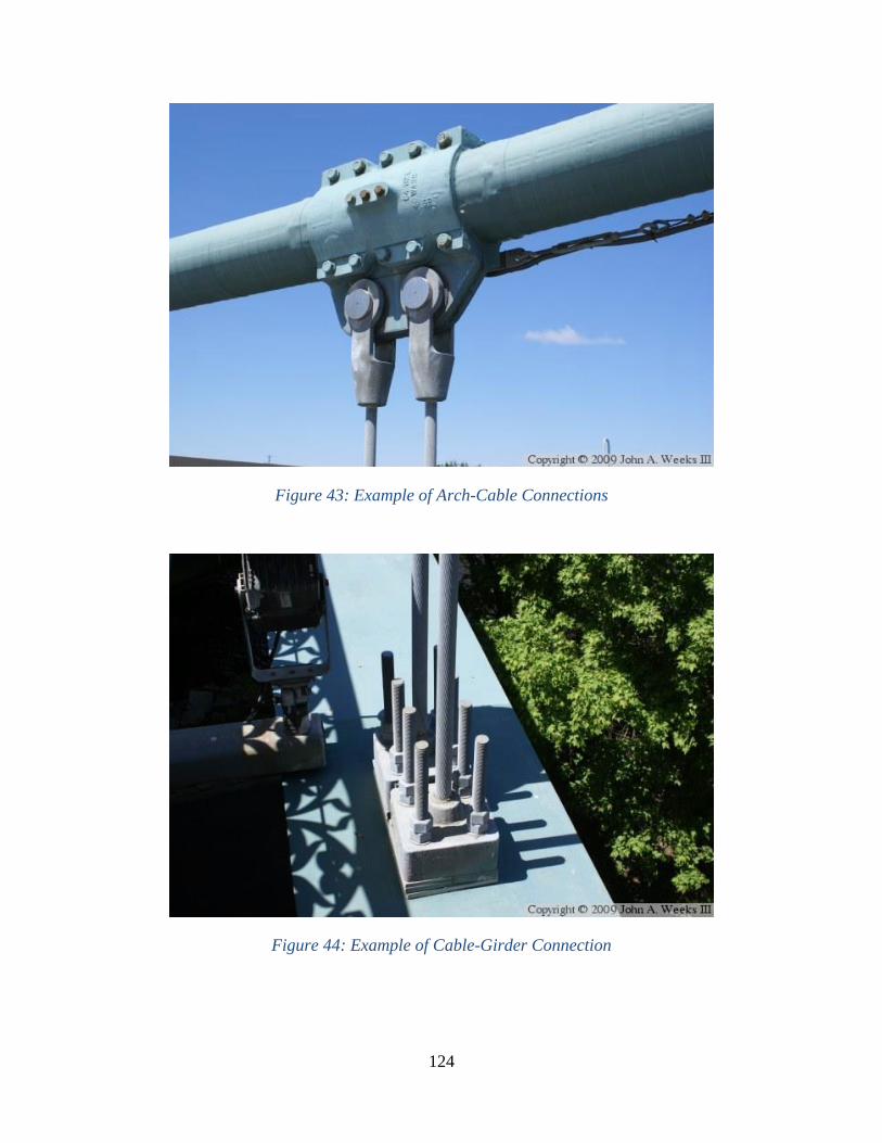
413 Truss Connections 36
42 Arch Design 37
421 Deflection 37
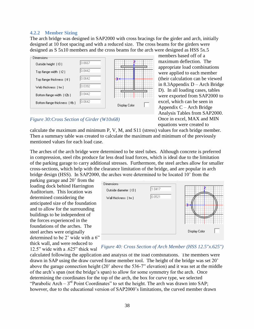
422 Member Sizing 38
40
423 Arch Connections 40
424 Fire truck Clearance 41
43
43 43 Foundation Design 43
431 Truss Pier Design 43
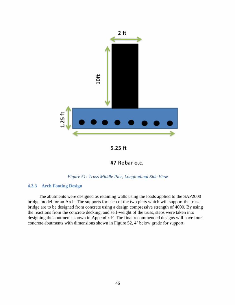
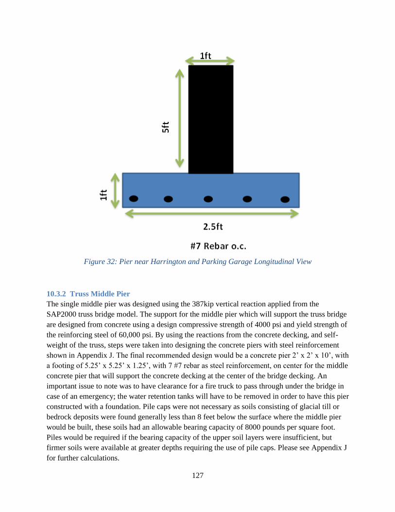
432 Truss Middle Pier 45
433 Arch Footing Design 46
5 Results 48
50 BIM 48
51 Schedule 49 50 50
52 Cost 50
6 Conclusions and Recommendations 52
60 Conclusions 52 61 Recommendations 52
611 Further Steps 53
7 Bibliography 54
8 Appendices 56
vii
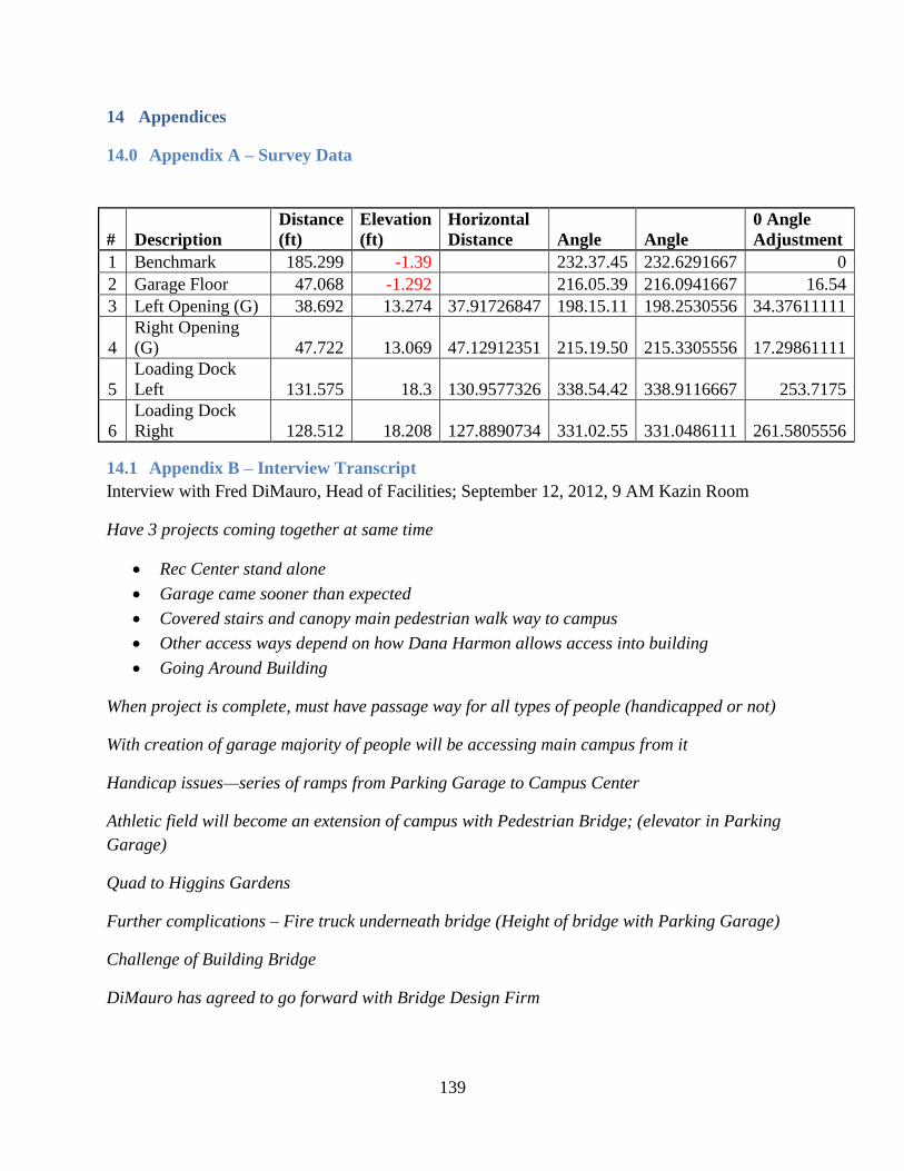
80 Appendix A ndash Survey Data 56 81 Appendix B ndash Interview Transcript 56 82 Appendix C ndash Arch Bridge Analysis Tables from SAP2000 59 83 Appendix D ndash Arch Bridge Deflection Tables 61
84 Appendix E ndash Arch Bridge Design Calculations 64 85 Appendix F ndash Arch Bridge Foundation Design Calculations 64 86 Appendix G ndash Truss Bridge Analysis Tables from SAP2000 70 87 Appendix H ndash Truss Bridge Deflection Tables 74 88 Appendix I ndash Truss Bridge Design Calculations 74
89 Appendix J ndash Truss Bridge Foundation Design Calculations 74 810 Appendix K ndash Bridge Deck Calculations 83 811 Appendix L ndash Bridge Cost Estimation 91 812 Appendix M ndash Arch Bridge Schedule Estimation 91
813 Appendix N ndash Truss Bridge Schedule Estimation 91 814 Appendix O ndash Building Information Modeling 91
815 Appendix O ndash Project Proposal Arsquo12 92
Table of Figures
Figure 1 Looking out of the New Recreation Center to the construction of the parking garage
and athletic fields (October 2012) 1
Figure 2 Overview of proposed pedestrian bridge location 4
Figure 3 EastWest Section of Garage Main Stair 5
Figure 4 Plan view of Main Stair at Field level 5
Figure 5 Planting plan showing the existing detailed grading 6
Figure 6 Hallen Bridge over the M5 Motorway in Great Britain 9
Figure 7 Merchants Bridge Manchester Great Britain 10
Figure 8 Common cross-sections of FRP decks from pultruded components 10
Figure 9 Basic Design Outline of Simply-Supported Beam Bridge 11
Figure 10 Simply-Supported Pedestrian Bridge Failure Lowesrsquo Motor Speedway North
Carolina 12
Figure 11 Various types of truss designs 14
Figure 12 Arch Nomenclature 14
Figure 13 Concrete True Arch 15
Figure 14 Horizontal Cable Connecting Hangers 15
Figure 15 Steel Tied-Arch Bridge 16
Figure 16 Arch with Diagonal Hangers 16
Figure 17 Transverse Cable Arrangements 16
Figure 18 Longitudinal Cable Arrangements 16
viii
Figure 19 Tower Configurations 17
Figure 20 Noncircular Handrail Cross Sections 18
Figure 21 Looking Towards the Loading Dock 19
Figure 22 looking Towards the Parking Garage 20
Figure 23 Garage in construction showing area of interest for foundation 22
Figure 24 James DeCelle Conducting Surveying Shots 26
Figure 25 Here the bridge decking will meet the Parking Garage 26
Figure 26 The Bridge Decking will meet with the Loading Docks behind Harrington 27
Figure 27 View From Harrington overlooking the construction Area the Parking Garage is in
the Distance 27
Figure 28 LRFD Load Combinations and Factors 29
Figure 29AISC Table 3-23 Case 10 30
Figure 30Cross Section of Girder (W10x68) 38
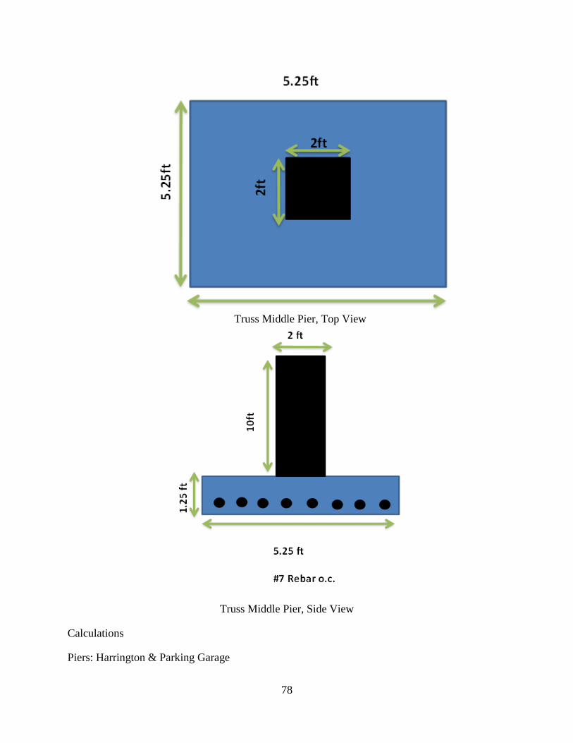
Figure 31 Pier Harrington and Parking Garage Top View 44
Figure 32 Pier Harrington and Parking Garage Longitudinal View 44
Table of Tables
Table 1 Design Parametershelliphelliphelliphelliphelliphelliphelliphelliphelliphelliphelliphelliphelliphelliphelliphelliphelliphelliphelliphelliphelliphelliphelliphelliphelliphelliphellip7
Table 2 Design Parametershelliphelliphelliphelliphelliphelliphelliphelliphelliphelliphelliphelliphelliphelliphelliphelliphelliphelliphelliphelliphelliphelliphelliphelliphelliphellip24
Table 3 Selection Criteriahelliphelliphelliphelliphelliphelliphelliphelliphelliphelliphelliphelliphelliphelliphelliphelliphelliphelliphelliphelliphelliphelliphelliphelliphelliphelliphellip25
Table 4 As-Built Surveyed Distanceshelliphelliphelliphelliphelliphelliphelliphelliphelliphelliphelliphelliphelliphelliphelliphelliphelliphelliphelliphelliphelliphellip28
Table 5 Unfactored LRFD Design Loadhelliphelliphelliphelliphelliphelliphelliphelliphelliphelliphelliphelliphelliphelliphelliphelliphelliphelliphelliphelliphellip29
Table 6 Applied Loadshelliphelliphelliphelliphelliphelliphelliphelliphelliphelliphelliphelliphelliphelliphelliphelliphelliphelliphelliphelliphelliphelliphelliphelliphelliphelliphelliphellip33
Table 7 Truss Guidelineshelliphelliphelliphelliphelliphelliphelliphelliphelliphelliphelliphelliphelliphelliphelliphelliphelliphelliphelliphelliphelliphelliphelliphelliphelliphelliphellip34
List of Electronic Files
Revit ndash Truss Model
Revit ndash Arch Model
SAP2000 ndash Truss
SAP2000 - Arch
Design Calculations and Load Analysis Tables - Truss
Design Calculations and Load Analysis Tables - Arch
Cost Estimate - Truss
Cost Estimate - Arch
Deck ndash Moment Calculations
Pier ndash Design Equations
Abutment ndash Design Equations
Pier ndash Design Spreadsheet
Abutment ndash Design Spreadsheet
ix
THIS PAGE WAS LEFT INTENTIONALLY BLANK
1
1 Introduction
Worcester Polytechnic Institute (WPI) an engineering and science institution of higher
education located in Worcester Massachusetts educates 3746 undergraduate students and 1557
graduate students and employs 425 employees (Management 2011) The student and faculty
population has experienced steady growth for many years but is now projected to slow due to a
limitation in the number of residence halls WPIrsquos student staff and faculty population generate a
large amount of parking demand that is currently met by the street parking plus the existing
parking facilities which consists of two parking garages (one on campus and one 1 mile off
campus) and nine parking lots many of them are only available to commuters or faculty As of
WPIrsquos 2004 master plan there were 785 surface lot spaces as well as 797 available street parking
spaces Unfortunately since then over 200 of the surface lot spaces have been removed to
accommodate new construction and 256 of the street spaces are in residential areas and are not
legal and are often unavailable during the winter months (Dec 1-Apr 1) due to snow A walk
through the streets reveals every side of the street full of parked cars with many people parking
on side streets because there are not enough places to park A lack of available parking
spacesareas has become a problem on campus at WPI
To more effectively deal with this problem WPI has funded and is currently building a new $20
Million parking garage which holds 534 vehicles to meet the current parking deficit and
projected future needs The parking garage is located at the site of an athletic field (softball
baseball and soccer field) which has now been relocated on the top of it (Figure 1)
Figure 1 Looking out of the New Recreation Center to the construction of the parking garage
and athletic fields (October 2012)
2
Access to and from the athletic field atop the garage is currently limited to the stairs and an
interior elevator constructed with the new Sports and Recreation Center as well as a makeshift
access ramp for snow removal vehicles along Park Avenue It is in WPIrsquos interest to construct a
bridge from the new field to the back of Harrington Auditorium to allow for convenient travel
between the field atop the garage and the center of campus in addition to snow removal vehicles
and equipment The bridge was discussed during the design phases of the Parking Garage and
Athletic Field but was put on hold due to the uncertain price of the Garage and Field at the time
WPI envisions the bridge as a key gateway to campus connecting what will be the largest
parking lot with the center of campus as well as providing a promenade for students and alumni
to take for spectating athletic events
This project explored alternative structural solutions for a pedestrian bridge to connect the field
atop of the new Parking Garage to the alleyway behind Harrington Auditorium at the Worcester
Polytechnic Institute Campus Four basic bridge types each consisting of steel or concrete were
initially considered Two alternatives a steel truss and steel arch bridges were designed in detail
SAP2000 software was used to support the calculation process A Building Information Model
was generated from the SAP2000 model to visualize the two alternatives The bridge deck and
the supporting bridge structure were also designed using cast-in-place reinforced concrete
THE REMAINDER OF THIS PAGE WAS LEFT INTENTIONALLY BLANK
3
2 Background
This chapter reviews bridge-related materials designs and construction techniques in order to be
able to later identify the most functional cost effective and aesthetically pleasing means of
providing what WPI wants from the structure It also reviews the context for the development of
this project at WPI
20 Assessing the Need for a Bridge
The need for a bridge was assessed by WPI and relayed to our team through interviews as well as
discussions with the general contractor for the parking garage
201 Interviews
On September 12 2012 we interviewed Fred DiMauro the Assistant Vice President of Facilities
at WPI which proved to be incredibly insightful in helping establish set goals and objectives for
our project The notes taken during the interview can be found in Appendix B The consideration
for a pedestrian bridge arose because of the construction of the parking garage An issue that
arose was that a means of egress to campus must be accessible for all types of people with
disabilities or not Currently an open stairway connects the parking garage to the upper
quadrangle There is also an elevator at the newly constructed Recreation and Sports Center that
can be used by individuals with disabilities to go from the lower level of the building and the
parking garage to the 3rd
floor at the quadrangle level Given the gradual change in the
configuration of the campus created by the construction of the new buildings the possibility arose
to creating an alternative public access to the campus from the parking garage and to make
access to the roof-top fields more convenient These issues led to the initial talks between
members of the Department of Facilities and the construction management company Gilbane to
obtain initial estimates for a new pedestrian bridge that would connect the parking garage to the
center of campus
Mr DiMauro explained that two complications arose after receiving estimates from design The
height underneath the bridge must be able to accommodate a fire truck and that the bridge must
be able to support vehicles such as snow removal equipment and small trucks for transferring
equipment on and off the fields
Mr DiMauro also explained that snow removal equipment and other vehicles can easily enter
onto the athletic field from Park Avenue via the highest elevation from the street level While
not ideal this temporary access can function until the bridge is fully constructed
To continue with this bridge design Mr DiMauro explained the process on how money is
allocated to fund a project from the trustees Firstly the need is recognized it is brought to the
attention of the Board of Trustees by the President of the university Dr Dennis Berkey and by
the administration to consider development and funding of the project Trustees receive
information and consideration on why said project is a priority while weighing in on other
campus needs and project options
4
Deliverables that Mr DiMauro would be glad to see from the outcome of this MQP are BIM
Model of proposed Bridge with a walk around 3D view design features site plan with structural
detail cost estimates and scheduling with construction timetables
21 Site Layout
The initial site layout data was provided by a survey taken by VHB (Vanasse Hangen Brustlin)
Inc the site engineer for the parking garage facility An excerpt from VHBrsquos grading drainage
erosion control and sedimentation plan for the garage and athletic field is below showing an
overview of the proposed pedestrian bridge site (Figure 2) The location of the start and end of
the bridge was specified by WPI The reasoning behind the location of the start of the bridge is
that it is located above a main entrance and near to both the stairs and elevator The end of the
bridge is located atop of existing loading dock for the Harrington Auditorium which leads to an
existing pathway connecting to the center of campus
Figure 2 Overview of proposed pedestrian bridge location
This site plan should be a close approximation of the initial conditions for the proposed
pedestrian bridge but should be verified by as-built plans before a final design is considered
The proposed bridge will span approximately 160rsquo As seen above the bridge span will come in
close proximity to the access road circle but will not cross over it The main issue with the
existing conditions is the location of the subsurface infiltration basin which consists of a series
of perforated 8rsquo diameter pipes which house the runoff from the recreation center These will not
be able to support any mid-span piers and therefore will need to be partially removed in order to
place a center pier
Bridge Start
Bridge End
Fire Truck
Access
5
The approximate elevation details have been obtained from the architectural plans for the new
garage prepared by SMMA (Symmes Maini amp McKee Associates) Below are excerpts from
SMMArsquos architectural plans and sections depicting an elevation of the main stair (Figure 3) and
a plan view of the main stair at the field level (Figure 4)
Figure 3 EastWest Section of Garage Main Stair
Figure 4 Plan view of Main Stair at Field level
Proposed
Bridge
Landing
Proposed
Bridge
Landing
6
The proposed bridge will rest in the opening between the steel columns that house the elevator
shaft and the staircase From these plans we determined that this opening has a width of 15rsquo 6rdquo
and is at an elevation of 536rsquo 7rdquo According to AASHTO the minimum pedestrian bridge width
is to be 8rsquo0rdquo which will constrain the bridge width to 8rsquo - 15rsquo6rdquo The proposed location is
highlighted in Figure 3 In addition the garage-side elevation forms the constraint for the
elevation of the other end of the bridge because of ADA (Americans with Disabilities Act)
regulations with cite a maximum grade of 50 for wheelchair access This means that over a
span of 160rsquo the bridge must fall within 536rsquo 7rdquo plusmn50 (8rsquo 0rdquo) We use this to determine where
the bridge will land on the loading dock in order to not exceed maximum grade and minimize the
required length of the bridge Below is an excerpt from SMMA planting plan which shows the
detail of the loading dock and proposed grading (Figure 5)
Figure 5 Planting plan showing the existing detailed grading
As seen above the top of the loading dock falls at an elevation of 541rsquo which will be well within
the ADA required 5 grade and minimizes the width in which the bridge must span without
excessive additional grading
One final site layout consideration that must be met is that the bridge must accommodate fire
trucks to mount the curb of the access road and drive under the bridge to access the west side of
the New Recreation Center (See Figure 2) The international fire code calls for a clear height of
13rsquo 6rdquo and a width of 12rsquo to account for the truck width of 8rsquo and 4rsquo of hose lying These are key
parameters and will define the type of bridge as a whole As seen in figure 5 the minimum grade
below the proposed bridge will be 522rsquo 0rdquo This 522rsquo contour comes within approximately 25rsquo of
the garage which will leave sufficient space on or below the minimum contour once the garage-
7
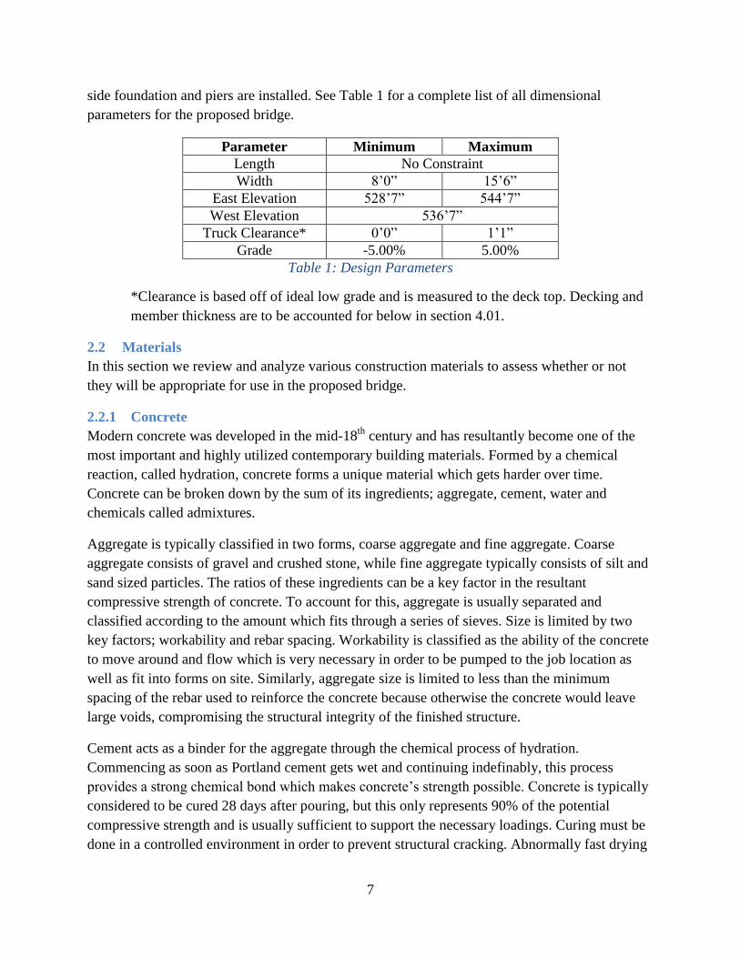
side foundation and piers are installed See Table 1 for a complete list of all dimensional
parameters for the proposed bridge
Parameter Minimum Maximum
Length No Constraint
Width 8rsquo0rdquo 15rsquo6rdquo
East Elevation 528rsquo7rdquo 544rsquo7rdquo
West Elevation 536rsquo7rdquo
Truck Clearance 0rsquo0rdquo 1rsquo1rdquo
Grade -500 500
Table 1 Design Parameters
Clearance is based off of ideal low grade and is measured to the deck top Decking and
member thickness are to be accounted for below in section 401
22 Materials
In this section we review and analyze various construction materials to assess whether or not
they will be appropriate for use in the proposed bridge
221 Concrete
Modern concrete was developed in the mid-18th
century and has resultantly become one of the
most important and highly utilized contemporary building materials Formed by a chemical
reaction called hydration concrete forms a unique material which gets harder over time
Concrete can be broken down by the sum of its ingredients aggregate cement water and
chemicals called admixtures
Aggregate is typically classified in two forms coarse aggregate and fine aggregate Coarse
aggregate consists of gravel and crushed stone while fine aggregate typically consists of silt and
sand sized particles The ratios of these ingredients can be a key factor in the resultant
compressive strength of concrete To account for this aggregate is usually separated and
classified according to the amount which fits through a series of sieves Size is limited by two
key factors workability and rebar spacing Workability is classified as the ability of the concrete
to move around and flow which is very necessary in order to be pumped to the job location as
well as fit into forms on site Similarly aggregate size is limited to less than the minimum
spacing of the rebar used to reinforce the concrete because otherwise the concrete would leave
large voids compromising the structural integrity of the finished structure
Cement acts as a binder for the aggregate through the chemical process of hydration
Commencing as soon as Portland cement gets wet and continuing indefinably this process
provides a strong chemical bond which makes concretersquos strength possible Concrete is typically
considered to be cured 28 days after pouring but this only represents 90 of the potential
compressive strength and is usually sufficient to support the necessary loadings Curing must be
done in a controlled environment in order to prevent structural cracking Abnormally fast drying
8
can cause tensile failures due to the uneven nature of the curing process To counteract this
problem it is important to control the moisture usually using a system of hoses and plastic
sheets to keep the surface moist
Water is the key ingredient in concrete and the ratio of water to cement helps determine the final
strength of the concrete The rule of thumb is to add the minimum amount of water necessary to
ensure that all of the cement gets wetted and also so that the concrete remains fully workable
until it is set in its forms The watercement ratio can range from 03 to 06 in most concrete
formulas Without enough water the concrete may harden prematurely and leave voids in the
finished product Too much water will weaken the compressive strength of the concrete and
could result in structural failures
Although concrete is traditionally a composite of aggregates cement and water various
admixtures have been developed over time to improve and adapt concrete to fit different needs
and environments Admixtures are known to accelerate and retard the curing process depending
on the extreme needs of a job site In addition air entrainment is common which is used to add
air bubble to the concrete which help absorb the impact of thermal expansion and reduce
cracking There are also plasticizers and pumping aids which can help increase the workability of
the product To suit certain environments there are also corrosion inhibitors and bonding agents
Lastly there is the ability to add pigment at the mixing stage which adds an architectural detail
which results in a smooth uniform finish
Concrete has become one of the most utilized building materials because of its superior
properties primarily its compressive strength which typically ranges from 3000 to 5000 psi
Many different forms of concrete exist which have significantly higher or lower strengths but
that value is most commonly used Concrete is also known for its durability fire resistance and
low coefficient of thermal expansion Lastly concrete has the ability to be put into decorative
forms which can add character in addition to pigment
In contrast concrete is very weak in tension and is resultantly reinforced with steel when
necessary Steel rebar is often bent and tied into place within formwork before pouring concrete
so that a composite material is formed which has both high compressive and tensile strengths
Another way is which concrete is strengthened is by pre-tensioning cables along a beam and
allowing the concrete to set This pre-stresses the materials and allows the concrete to be used
effectively as a beam The other large weakness of concrete is water invasion When water gets
into small cracks and freezes it can wedge to form larger cracks which are known to be
structurally compromising In addition water serves to corrode any steel reinforcement As a
result any methods of reducing water invasion can be very beneficial to the long term strength
and durability of any concrete structure (Neville 1995)
9
222 Steel
Steel is another commonly used material in modern construction When it comes to the
design of bridges steel offers many attractive advantages One of the most important advantages
gained through the use of steel is its high strength to weight ratio This may be a crucial
advantage when it comes to the design of the new pedestrian bridge This superior ratio could
have many positive impacts on the design of the bridge One of the most important factors that
the high strength to weight ratio could impact is that it will allow the bridge to carry a greater
load for a shallower depth Since we are tightly constrained on the bridge depth due to fire code
requirements this would be an ideal material to utilize because it can transfer a greater load at a
shallower depth Additionally the transportation and placement of the beams required may be
easier due to their low self-weight Steel may also contribute in the reduction of construction
time During bridge construction one of the exitsentrances to the new parking garage will need
to be closed as well as the stairway located between Harrington Auditorium and the new
recreation center It is easy to see why the closing of this area for an extended period of time
during the WPI school year would be unfavorable With many of the components of the bridge
being prefabricated construction time would be greatly minimized There have even been
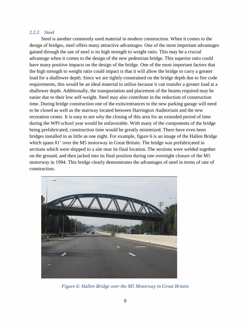
bridges installed in as little as one night For example figure 6 is an image of the Hallen Bridge
which spans 81rsquo over the M5 motorway in Great Britain The bridge was prefabricated in
sections which were shipped to a site near its final location The sections were welded together
on the ground and then jacked into its final position during one overnight closure of the M5
motorway in 1994 This bridge clearly demonstrates the advantages of steel in terms of rate of
construction
Figure 6 Hallen Bridge over the M5 Motorway in Great Britain
10
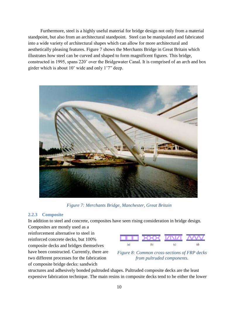
Furthermore steel is a highly useful material for bridge design not only from a material
standpoint but also from an architectural standpoint Steel can be manipulated and fabricated
into a wide variety of architectural shapes which can allow for more architectural and
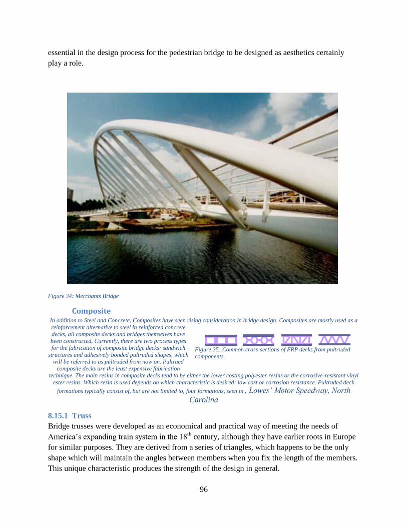
aesthetically pleasing features Figure 7 shows the Merchants Bridge in Great Britain which
illustrates how steel can be curved and shaped to form magnificent figures This bridge
constructed in 1995 spans 220rsquo over the Bridgewater Canal It is comprised of an arch and box
girder which is about 10rsquo wide and only 1rsquo7rdquo deep
Figure 7 Merchants Bridge Manchester Great Britain
223 Composite
In addition to steel and concrete composites have seen rising consideration in bridge design
Composites are mostly used as a
reinforcement alternative to steel in
reinforced concrete decks but 100
composite decks and bridges themselves
have been constructed Currently there are
two different processes for the fabrication
of composite bridge decks sandwich
structures and adhesively bonded pultruded shapes Pultruded composite decks are the least
expensive fabrication technique The main resins in composite decks tend to be either the lower
Figure 8 Common cross-sections of FRP decks
from pultruded components
11
costing polyester resins or the corrosive-resistant vinyl ester resins Which resin is used depends
on which characteristic is desired low cost or corrosion resistance Pultruded deck formations
typically consist of but are not limited to four formations seen in Figure 8 All of the deck
formations typically have a dead load associated with them between 18 and 23 lbsft2 are about
7-34rdquo thick cost about $74ft2 and have a normalized deflection (HS20+IM for 24m center-to-
center span) between L325 and L950 depending on the cross section (Zhou 2002) Zhou
suggests that the amount of deflection in different deck cross sections can be attributed to the
process in which the bridges are designed which is varied
Composite bridge decks have been found to have a long service life in comparison to steel and
concrete decks which is an important and helpful feature of composites Vistasp M Kabhari
Dongqong Wang and Yanqiang Gao studied numerous bridges in the US and found that while
bridges last on average for 68 years however their decks tend to last for only 35 years
Although this considers vehicular bridges and not pedestrian bridges it is common acceptance
that bridge decks need more maintenance and repairing than any other component of a bridge
Composite bridge decks are highly corrosion-resistant which eliminates maintenance concerns
from moisture and salt air The longer service life and durability of composites can help lengthen
the life of the bridge deck (Zhou 2002) Composites also tend to have higher strength to weight
ratios when compared to concrete and steel decks and have a weight of about 80 less than cast
in place concrete decks (Malvar 2005) The lighter weight of the composite decks allow for
better constructability along with the prefabrication and ability to have the deck shipped
completely or partially assembled Unfortunately one of the drawbacks of the composite bridge
decks is their initial cost Composite bridges decks typically cost about 4-5 times that of purely
concrete decks 4 times that of reinforced concrete decks and 2-3 times that of steel decks when
considering cost per ft2 However the high initial cost of composite bridge decks may be offset
when considering the lower maintenance costs but life cycle cost analyses of composite bridges
have yet to emerge (Zhou 2002)
23 Bridge Systems
231 Simply Supported Beam
Bridges designed as simply-supported have
multiple characteristics that may be seen as
advantageous In the design phase simply-
supported structures are rather simple to design
Figure 9 shows the basic look of a simply-
supported beam design The loading on the bridge
is transferred through the main beam into the
support piers and then down into the ground
below As shown in Figure 9 the beam may
require an additional support located in the center
Figure 9 Basic Design Outline of
Simply-Supported Beam Bridge
12
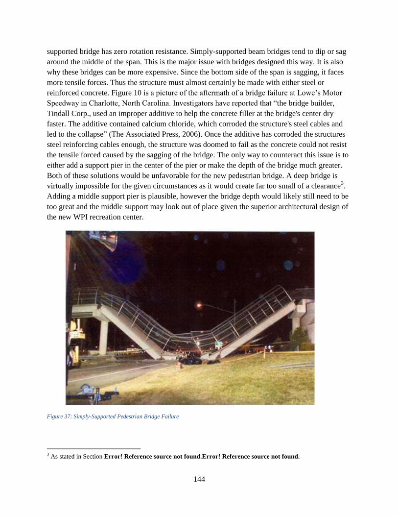
of the span if the span length is too long This is due largely to the fact that a simply-supported
bridge has zero rotation resistance Simply-supported beam bridges tend to dip or sag around the
middle of the span This can be a major issue with bridges designed this way It is also why these
bridges can be more expensive Since the bottom side of the span is sagging it faces more tensile
forces Thus the structure must almost be made with either steel or pre-stressed concrete Figure
10 is a picture of the aftermath of a bridge failure at Lowersquos Motor Speedway in Charlotte North
Carolina Investigators have reported that ldquothe bridge contractor Tindall Corp used an improper
additive to help the concrete filler at the bridges center dry faster The additive contained
calcium chloride which corroded the structures steel cables and led to the collapserdquo (The
Associated Press 2006) Once the additive has corroded the structures steel reinforcing cables
enough the structure failed as the concrete could not resist the tensile forced caused by the
sagging of the bridge Although this isolated incident was an issue with material design it
illustrates how vulnerable certain types of bridges can be to material mistakes and defects
Although simply-supported bridges can be simple and cheap both of these solutions would be
unfavorable for the new pedestrian bridge The depth required by this type of bridge makes it
virtually impossible for the given layout as it would create far too small of a clearance for the fire
code requirement In addition a middle support pier will add cost and complication to the
project Lastly it was chosen as the least aesthetically pleasing design choice
Figure 10 Simply-Supported Pedestrian Bridge Failure Lowesrsquo Motor Speedway North
Carolina
13
232 Truss
Bridge trusses were developed as an economical and practical way of meeting the needs of
Americarsquos expanding train system in the 18th
century although they have earlier roots in Europe
for similar purposes They are derived from a series of triangles which happens to be the only
shape which will maintain the angles between members when you fix the length of the members
This unique characteristic produces the strength of the design in general
Because of the stresses on the members of any truss they are typically constructed out of
materials with high tensile strengths Initially they were constructed out of wood but as iron was
developed into steel steel became a more popular material for the construction of trusses More
recently especially in the case of pedestrian bridges prefabricated trusses have become more
popular This way a bridge is constructed economically and safely under controlled conditions at
a factory Afterwards it is simply lifted into place using a crane which minimizes onsite costs
Prefabricated bridges were initially developed by the British military in the 1930s and eventually
found their way into commercial bridge manufacturing
There is a lot of terminology related to understanding truss bridges which allows for analysis
First trusses can be classified as planar which means that all members fall into a 2 dimensional
plane or special which means that members venture out into 3 dimensions The point of contact
between members is called a node For the purpose of analysis nodes are considered to be
simple pins which cannot create a moment between members but in reality these connections
can exert a small moment Stringers are the members that connect parallel trusses and typically
act perpendicularly to the direction of travel Stringers also provide support for the floor beams
which subsequently supports the decking Struts and bracing help prevent torsion between
parallel trusses by providing diagonal bracing against wind and seismic loads The upper edge
and lower edge of a planar truss are referred to the top chord and bottom chord respectively Any
other diagonal members in the truss are considered web members which help distribute the load
Simple analysis of truss bridges can be completed through static analysis of Newtonrsquos laws In
reality a bridge is rarely a statically determinate system and must be analyzed as such This is
where software comes in to help quickly and accurately analyze the viability of different designs
There are countless examples of different truss types which can excel in different situations and
loadings as seen below in Figure 11
14
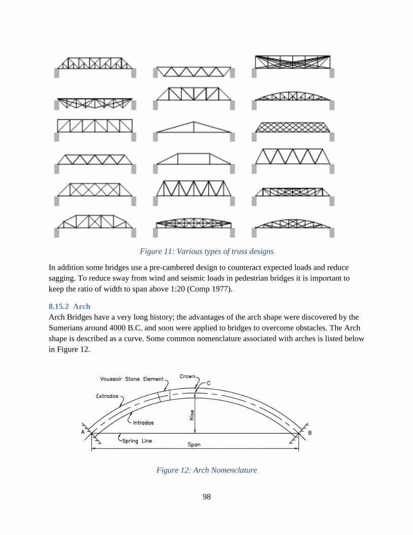
Figure 11 Various types of truss designs
In addition some bridges use a pre-cambered design to counteract expected loads and reduce
sagging To reduce sway from wind and seismic loads in pedestrian bridges it is important to
keep the ratio of width to span above 120 (Comp 1977)
233 Arch
Arch Bridges have a very long history the advantages of the arch shape were discovered by the
Sumerians around 4000 BC and soon were applied to bridges to overcome obstacles The Arch
shape is described as a curve Some common nomenclature associated with arches is listed below
in Figure 12
Figure 12 Arch Nomenclature
15
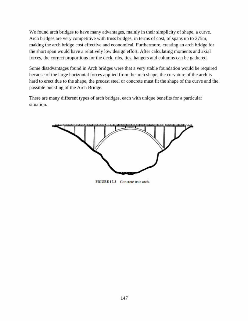
We found arch bridges to have many advantages mainly in their simplicity of shape Arch
bridges are very competitive with truss bridges in terms of cost for spans up to 900 feet making
the arch bridge cost effective and economical (Fox 2000) Furthermore creating an arch bridge
for the short span would be relatively simple to design After calculating moments and axial
forces the correct proportions for the deck ribs ties hangers and columns can be gathered
Some disadvantages with arch bridges are that a very stable foundation is required because of the
large horizontal forces applied from the arch shape In addition the curvature of the arch is
complex to form because the precast steel or concrete must fit the shape of the curve to prevent
possible buckling of the bridge
There are many different types of arch bridges each with unique benefits for a particular
situation Some common variances are seen below in Figures 13 14 15 and 16
Figure 13 Concrete True Arch
Figure 14 Horizontal Cable Connecting Hangers
16
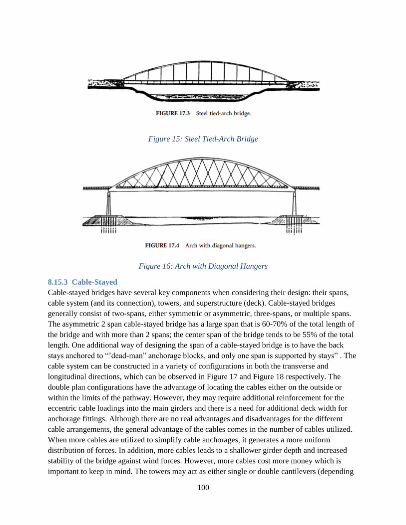
Figure 15 Steel Tied-Arch Bridge
Figure 16 Arch with Diagonal Hangers
234 Cable-Stayed
Cable-stayed bridges have several key components when considering their design their spans
cable system (and its connection) towers and superstructure (deck) Cable-stayed bridges
generally consist of two-spans either symmetric or asymmetric three-spans or multiple spans
The asymmetric 2 span cable-stayed bridge has a large span that is 60-70 of the total length of
the bridge and with more than 2 spans the center span of the bridge tends to be 55 of the total
length One additional way of designing the span of a cable-stayed bridge is to have the back
stays anchored to ldquorsquodead-manrdquo anchorage blocks and only one span is supported by staysrdquo
(Podolny Jr) The cable system can be constructed in a variety of configurations in both the
transverse and longitudinal directions which can be observed in Figure 17 and Figure 18
Figure 17 Transverse Cable Arrangements Figure 18 Longitudinal Cable Arrangements
17
respectively The double plan configurations have the advantage of locating the cables either on
the outside or within the limits of the pathway However they may require additional
reinforcement for the eccentric cable loadings into the main girders and there is a need for
additional deck width for anchorage fittings Although there are no real advantages and
disadvantages for the different cable arrangements the general advantage of the cables comes in
the number of cables utilized When more cables are utilized to simplify cable anchorages it
generates a more uniform distribution of forces In addition more cables leads to a shallower
girder depth and increased stability of the bridge against wind forces However more cables cost
more money which is important to keep in mind The towers may act as either single or double
cantilevers (depending on whether single of double plane cables are used) The difference
between single and double cantilevered towers is that single cantilevered towers stay within the
vertical planes while double cantilevered towers lsquoleanrsquo out of plane Single and double plane
cables follow a similar rule where single cables are purely vertical and double plane cables have
an angle to them The design of the towers themselves must consider two main components the
base and the frame The base of the towers can be either fixed or hinged Fixed bases induce
large bending moments at the base of the tower but offer increased rigidity of the total structure
and can be more practical to erect Hinge-based towers need to be externally supported until the
cables are connected The frame of the towers is typically designed in three basic ways Modified
A-Frame Diamond or Modified Diamond or Delta seen in 19 The design of the frames can be
mostly considered based on aesthetics however the diamond and modified diamond or delta
frames offer additional height clearance and less pier width compared to the modified A-frame
tower The tower heights are usually 20 of the length of the main span although this can vary
depending on the specific bridge (Azamejad McWhinnie Tadros amp Jiri 2011) The bridge deck
depends on the material chosen (concrete steel or composite) Each has their own advantages
and disadvantages however the advantage that cable-stayed bridges offer for the bridge decks a
higher span to depth ratio Although the ratio itself is highly variable (due to the number of
cables used materials etc) the ratio for two span asymmetric can be 100 by anchoring back
stays to the girder directly over the piers and in general bridges that are double plane with
multi-stays have a ratio between 120 and 260 (Podolny Jr)
Although cable-stayed bridges are more commonly used when bridges need to be lightweight
(poor soil conditions or large spans) they can be
considered for short pedestrian bridges (Godden 1997)
Cable-stayed bridges offer additional clearance
compared to girder bridges because they eliminate the
necessary piers of the simply supports bridges
Although aesthetics is always a matter of opinion
cable-stayed bridges are typically considered more
aesthetically pleasing and they have numerous options
for the design of the cables allowing for more
variability in appearance The span moments can be Figure 19 Tower Configurations
18
controlled by the spacing of the cables to make the moment along the span more uniformly
distributed (Podolny Jr) Due to the added cable forces in the cable-stayed bridges large
connection and girder support is needed to accommodate the cables Design considerations must
also include wind loads due to the one way support of the cables which can result in significant
movement to the bridge deck if the deck is not restrained properly Cable-stayed bridges also
tend to be more expensive than a truss or simply supported bridge especially in areas in which
contractors and engineers donrsquot necessarily have the expertise in cable-stayed bridge design or
construction
24 Design Criteria
241 Americans with disabilities Act (ADA)
One of the requirements of any structure designed and constructed in the United States is to
comply with the regulations set forth by the Americans with Disabilities Act (ADA) The ADA
was recently updated in 2010 and these updated standards must be complied with if the start of
construction date is on or after March 15 2012 which will be the case for our bridge In the
updated standards the requirements applicable or may be applicable consist of sections 3023
3032 3033 3034 305 307 4022 403 404 405 505 and 6098
Section 3023 and section 303 consists of details regarding the walking surface of the bridge
stating that the walking surface shall be ldquostable firm and slip resistantrdquo 3023 states that if there
are any openings such as a grated surface the openings shall not exceed frac12rdquo Sections 303 state
that there shall be no vertical change greater than frac14rdquo The surface may be beveled between frac14rdquo
and frac12rdquo with a slope no greater than 12 if need be If the surface is to be ramped (change in
height greater than frac12rdquo) the surface must comply with sections 405 or 406 which ultimately state
that ramps with a rise of greater than 6rdquo must have
handrails installed
Sections 402 and 403 deal with the limitations of the
walking surface such as the running slope shall not
exceed 120 the cross slope shall not exceed 148 and the
clearing width for each lane of travel shall not be less than
60rdquo (which means our bridge must be able to support 10rsquo
for the expected 2 directions of travel) Section 505 deals
with the application and design of the handrails stating
that they must be continuous along the entirety of the walking surfaces length Additionally the
handrails must be 34-38rdquo above the walking surface and have at least 1-12rdquo minimum clearance
between the rail and any adjacent surface The gripping surface of the handrails must also be
unobstructed for at least 80 of its length (with a 1-12rdquo minimum bottom clearance when
obstructed) and shall be free of sharp or abrasive elements The handrails shall have rounded
edges and if circular have an outer diameter between 1-14rdquo to 2rdquo If the handrail is
nonrectangular the perimeter shall be between 4 and 6-14rdquo but with a cross-section dimension
Figure 20 Noncircular Handrail
Cross Sections
19
not exceeding 2-14rdquo (as seen above in Figure 20) Section 6098 states that the allowable stress
in the handrails ldquoshall not be exceeded for the materials used when a vertical or horizontal force
of 250 pounds is applied at any point on the handrail fastener mounting device or supporting
structure Section 5059 further states that the handrails shall not rotate (Department of Justice
2010)
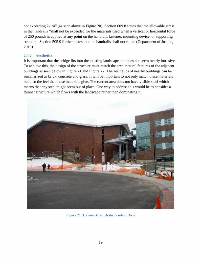
242 Aesthetics
It is important that the bridge fits into the existing landscape and does not seem overly intrusive
To achieve this the design of the structure must match the architectural features of the adjacent
buildings as seen below in Figure 21 and Figure 22 The aesthetics of nearby buildings can be
summarized as brick concrete and glass It will be important to not only match these materials
but also the feel that these materials give The current area does not have visible steel which
means that any steel might seem out of place One way to address this would be to consider a
thinner structure which flows with the landscape rather than dominating it
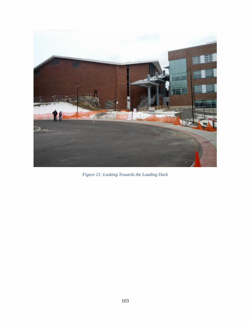
Figure 21 Looking Towards the Loading Dock
20
Figure 22 looking Towards the Parking Garage
Since WPI is a science and engineering university there is also potential for an architecturally
significant or structurally significant design This could make the bridge less of an object fitting
into the existing landscape and more of a landmark for the school
243 Site amp Constructability
Constructability is an important factor when considering design parameters for the proposed
pedestrian bridge We must also consider how long construction will take and how it can be
scheduled to avoid conflicts with academic and sporting activities In addition there is a concern
that the access road to the garage may need to be temporarily closed during parts of construction
These are important questions that need to be answered It is in the best interest of WPI for
construction to take place during the summer months between the months of May and August
when majority of students and faculty are away from campus and pedestrian traffic will be at a
minimum since the main entrance to the garage and field lies directly under the proposed
location of the bridge If possible the design team should select a bridge that will be able to be
constructed in this window In addition the garage access road ends at a turn-around right before
the proposed bridge so only a partial closure of the turn-around should be required The turn-
around could be used for staging of construction material as well as a stable area for a crane
21
during erection of the superstructure Although the access road provides egress to the North
there is very little access form the east and almost no access from the south and west sue to the
adjacent buildings and running track It is a very tight site and must be able to accommodate
traffic and student athletic uses during construction In addition the construction cannot block off
fire access to the new recreation center
244 Economy
A major design parameter in our research for a bridge is the budget Currently there is no set
budget for this project because there is no official bridge design chosen However initial
estimates were given by Fred DiMauro with $300000 USD allocated to the bridge with
$1000000 being a maximum feasible cost for the bridge promenade and site work Alternative
procedures will be investigated to decrease the cost of the bridge such as looking into different
designs construction materials and the construction processes
245 Environment
Environmental impacts should always be considered during any construction However since the
bridge will be located in an area that has seen 2 extensive construction projects it is assumed that
the construction of the bridge would have little to no additional impacts Still an environmental
impact report would need to be considered if construction of the bridge were to be approved
246 Fire Code
The Commonwealth of Massachusetts is the authority having jurisdiction over Worcester County
and with neither having a proper fire code for pedestrian bridges it is advisable to follow the
International Fire Code (IFC) under section 50326 for Bridges which states
ldquoWhere a bridge or an elevated surface is part of a fire apparatus access road the bridge shall
be constructed and maintained in accordance with AASHTO HB-17rdquo
This code calls for a clear height of 13rsquo6rdquo as well as a width of 12rsquo0rdquo for fire trucks (Code 2000)
Worcester County considers this to be a fire apparatus access road because in the event of a fire
in the new recreation center there would be no other direct access to the back of the building
ldquoBridges and elevated surfaces shall be designed for a live load sufficient to carry the imposed
loads of fire apparatusrdquo
The above excerpt from IFC suggests that the bridge should be able to support the weight of the
truck but according to Fred DiMauro it is unnecessary to design for a Fire truck to travel over
the bridge
ldquoVehicle load limits shall be posted at both entrances to bridges when required by the fire code
officialrdquo
The above excerpt from IFC will be important to keep in mind to designate the maximum
allowed vehicle weight on the bridge
22
It is vital to note that fire codes are considered somewhat flexible in that they should be adapted
to the situations present IFC is used as a guide not an infallible law The Worcester Fire
Department will be required to sign off on all plans before construction so design work should
be coordinated to meet their needs in the event of a fire
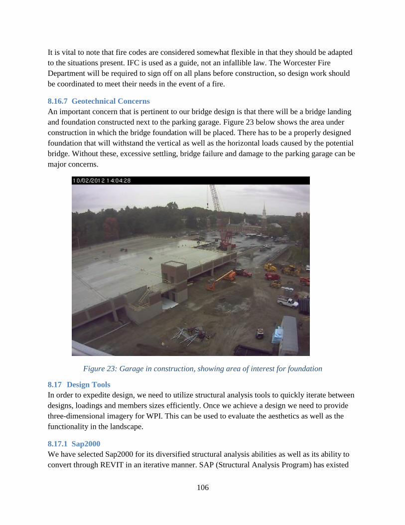
247 Geotechnical Concerns
An important concern that is pertinent to our bridge design is that there will be a bridge landing
and foundation constructed next to the parking garage Figure 23 below shows the area under
construction in which the bridge foundation will be placed There has to be a properly designed
foundation that will withstand the vertical as well as the horizontal loads caused by the potential
bridge Without these excessive settling bridge failure and damage to the parking garage can be
major concerns
Figure 23 Garage in construction showing area of interest for foundation
25 Design Tools
In order to expedite design we need to utilize structural analysis tools to quickly iterate between
designs loadings and members sizes efficiently Once we achieve a design we need to provide
three-dimensional imagery for WPI This can be used to evaluate the aesthetics as well as the
functionality in the landscape
251 Sap2000
We have selected Sap2000 for its diversified structural analysis abilities as well as its ability to
convert through REVIT in an iterative manner SAP (Structural Analysis Program) has existed
23
for many years and is considered a premium analysis software suite around the world It has been
used in many structures such as dams bridges and even the worldrsquos tallest building The user
interface is known to be intuitive mirroring tools available in other CAD software for easy cross
over Sap2000 contains all applicable structural codes necessary to be accounted for in addition
to a material library for quick changes and further analysis SAP2000 can perform analyses
based on deflection limits as well as failure modes and allows for analysis of different load
combinations simultaneously
252 BIM
Building Information Modeling (BIM) is a process developed into a software package which
represents various systems of a building in three special dimensions In addition more recently a
4th
dimension time (4D BIM) has been integrated This way 4D BIM allows the visual
representation of both the construction and cost of the building as it is built in accelerated time
BIM allows for the expedited design of various buildings and structures with an integrated
library of materials and structural components We will utilize REVIT a software suite owned
by Autodesk to design our bridge in addition to the site layout and adjacent buildings This will
save time on several levels First skipping the traditional time factor of two dimensional
modeling will save time in constructing three dimensional renderings for WPI later and add the
ability to visualize conflicts In addition the structural data may be exported from SAP2000 for
via an IFC file which can be imported into REVIT to create a detailed visual representation of
the bridge and its surroundings
THE REMAINDER OF THIS PAGE WAS LEFT INTENTIONALLY BLANK
24
3 Preliminary Design
Our design process began with our parameters from Section 21 With these ranges and all
applicable codes from Section 24 in mind we began to select proposed dimensions to begin
design The bridge length was constrained be the elevations as described in section 21 which we
later verified by performing our own site survey (see section 32 below) The width was to be
between 8rsquo0rdquo and 15rsquo6rdquo and we chose a width of 14rsquo0rdquo to accommodate larger vehicles and
provide a significant looking promenade between campus and the fields per WPIrsquos wishes The
elevations from Section 21 were constrained by existing site features and were later verified by
our field survey The final grade was calculated as +276 from the parking garage to the
loading dock which is well within ADArsquos lt5 requirement The final proposed dimensions are
summarized below in Table 2 along with the constraints from Section 21
Parameter Minimum Maximum Proposed
Length No Constraint 160rsquo 0rdquo
Width 8rsquo0rdquo 15rsquo6rdquo 14rsquo0rdquo
East Elevation 528rsquo7rdquo 544rsquo7rdquo 541rsquo0rdquo
West Elevation 536rsquo7rdquo 536rsquo7rdquo
Truck Clearance 0rsquo0rdquo 1rsquo1rdquo 1rsquo1rdquo
Grade -500 500 +276
Table 2 Design Parameters
The process continued by selecting two bridge types as well as materials which is discussed
below in Section 30 We continued by pulling information from the construction documentation
provided to us by Gilbane for the garage and recreation center (Section 31) The next step in the
process was to take our own survey data to provide accurate dimensions for analysis in Sap2000
described in Section 32 Lastly we selected loadings and load combinations which we discuss
below in section 33
30 Selection Criteria
A number of criteria were used to determine feasible alternatives given the requirements and
constraints provided WPI with the best solution These criteria included depth cost aesthetics
sustainabilitymaintenance and constructability Depth of the bridge superstructure is the most
important aspect because it constrains the entire design Cost is also a major criterion as the
project will likely have a budget of around $1000000 USD (Section 201) The costs will
include cost of materials labor and transporting the materials Aesthetics plays a major role as
the bridge will be part of WPIrsquos new promenade and main gateway to campus The bridge must
look worthy and cannot look out of place with the new recreation center located directly behind
it Aesthetics were measured by group consensus Sustainabilitymaintenance is important as it
would be favorable to use materials that will not need to be repaired constantly Also it is
preferred that the material used be recyclable upon the end of its life-span Finally the
constructability criteria favored alternatives and materials that were less time consuming to
implement as well as less difficult to erect into position See Table 3 below for our ranking of
25
each alternative With 1 being the best and 4 being the worst the rankings are purely relative to
each other and are not quantifiable beyond their relation to each other
Selection Criteria
Bridge Type More Important Less Important
Depth Cost Aesthetics Maintenance
Truss 2 2 2 2
Simply- Supported Beam 3 1 3 1
Arch 1 3 1 2
Cable-Stayed 1 5 1 2
Arch-Cable
Suspension
1 4 1 2
Table 3 Selection Criteria
After this evaluation we decided to only continue with an arch bridge and a truss bridge We
discounted the simply supported bridge due to its excessive depth and lack of aesthetic appeal In
addition we discounted the cable-stayed bridge because outlying cost
Materials were evaluated separately since not every material can be applicable to every type of
bridge Specific application and discounting of materials is discussed below in Section 33
31 Construction Documents
We obtained construction plans for the new parking garage from Gilbane These plans included
site plans drainage plans and foundation plans In addition we obtained geotechnical reports that
allowed us to determine preliminary soil characteristics on the site We determined that the soil is
of good quality with shallow bedrock and also that the foundation for the parking garage should
not interfere with the piers on the west end of the proposed bridge The drainage plans show
storm water infiltration pipes directly underneath the majority of the span of the bridge After
discussing with Gilbane we determined that some of these could easily be excavated and
removed if necessary in order to support a middle pier In looking at the grading plans and
evaluating the storm water infiltration pipe manufacturerrsquos specifications we determined that the
pipes were buried to the minimum allowable depth under the bridge so any site work could not
effectively lower the grade
32 Site Survey
Although the project began while the Parking Garage was still under construction the project
team had the advantage of performing a site survey of as-built conditions to ensure that the
measurements recorded and assumed in the construction documents regarding the height and
length from the loading dock at Harrington Auditorium to the elevator landing on the Parking
Garage were accurate
26
Figure 24 James DeCelle Conducting Surveying Shots
Figure 25 Here the bridge decking will meet the Parking Garage
27
Figure 26 The Bridge Decking will meet with the Loading Docks behind Harrington
The group used a benchmark in the parking garage that Gilbane referred us to This allowed us
to determine the height of the gun and record the angles of all subsequent shots which would be
used to determine the distances between points The subsequent shots identified the left and
right opening at the elevator shaft in the parking garage and the left and right connection points
at the loading dock by Harrington Auditorium
Figure 27 View From Harrington overlooking the construction Area the Parking Garage is in
the Distance
28
Once the information was recorded a simple excel spreadsheet and the application of the law of
cosines was used to determine the distances between the loading dock and the parking garage
connection as well as their heights The results can be observed in the summary table in
Appendix B
The results were almost identical to the assumptions made from the construction documents thus
confirming the bridgersquos span and height requirements The resultant distances are summarized
below in Table 4
(FT)
Distance L-L 16207
Distance R-R 15430
Delta Elevation
L-L 503
Delta Elevation
R-R 514
Dock Width 1801
Opening Width 1557
Table 4 As-Built Survey Distances
33 Deflection amp Load Requirements
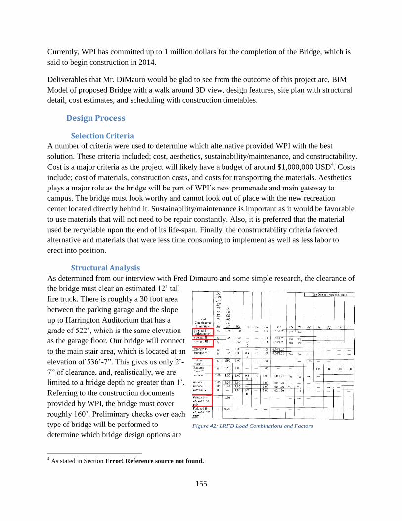
As determined from our interview with Fred DiMauro and independent research the clearance of
the bridge must clear an estimated 13rsquo6rdquo tall fire truck There is roughly a 30 foot area between
the parking garage and the slope up to Harrington Auditorium that has a grade of 522rsquo which is
the same elevation as the garage floor Our bridge will connect to the main stair area which is
located at an elevation of 536rsquo-7rdquo This gives us only 1rsquo-1rdquo of clearance and realistically we are
limited to a bridge depth no greater than 1rsquo Our site survey determined that the bridge must
cover a maximum distance of 162rsquo1rdquo Preliminary checks over each type of bridge were
performed to determine which bridge design options are viable for these conditions The main
check is a simple deflection limit check to determine the minimum depth of each bridge design
and those that are too deep were immediately deemed not viable We then took the two
remaining viable bridge designs and proceeded into advanced design for them below in section
41 and 42 using the following loadings
The Load and Resistance Factor Design (LRFD) was used to design all bridge members
components and connections The ASSHTO Guide Specifications for Design of Pedestrian
Bridges (2009) were used along with any other AASTHO material referenced Figure 28 as
seen below shows the different load combinations as provided by AASHTO The AASHTO
Pedestrian Bridge Design Guide states that for pedestrian bridges strengths II IV and V may
be ignored Furthermore the load factor for fatigue I load combination were taken as 10 (not
150) and fatigue II was ignored The AASHTO design guide also specified the deflection limits
for pedestrian bridges They were investigated at the service limit using service I and may not
exceed L220 for cantilever arms or L360 for spans other than cantilever arms due to the
29
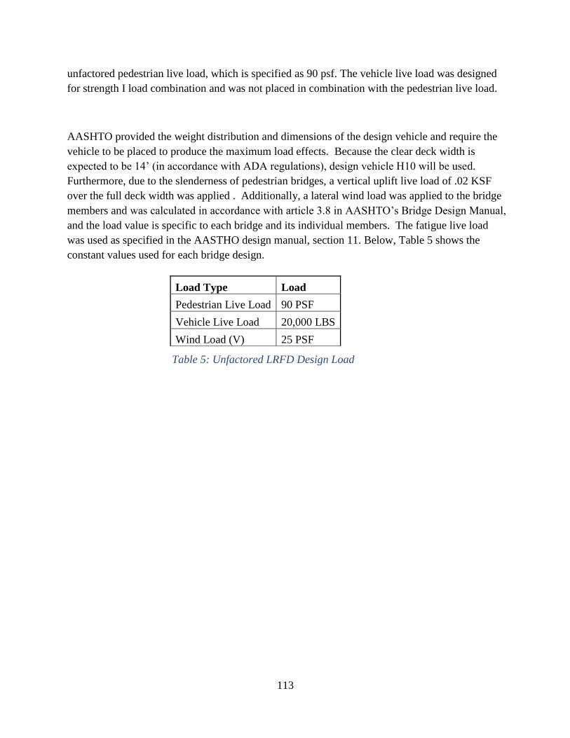
unfactored pedestrian live load which is specified as 90 psf The vehicle live load was designed
for strength I load combination and was not placed in combination with the pedestrian live load
AASHTO provided the weight distribution and dimensions of the design vehicle and require the
vehicle to be placed to produce the maximum load effects Because the clear deck width is
expected to be 14rsquo (in accordance with ADA regulations) design vehicle H10 will be used
Furthermore due to the slenderness of pedestrian bridges a vertical uplift live load of 02 KSF
over the full deck width was applied (AASHTO 2009) Additionally a lateral wind load was
applied to the bridge members and was calculated in accordance with article 38 in AASHTOrsquos
Bridge Design Manual and the load value is specific to each bridge and its individual members
The fatigue live load was used as specified in the AASTHO design manual section 11 Below
Table 5 shows the constant values used for each bridge design
Load Type Load
Pedestrian Live Load 90 PSF
Vehicle Live Load 20000 LBS
Wind Load (V) 25 PSF
Table 5 Unfactored LRFD Design Load
Figure 28 LRFD Load Combinations and Factors
30
4 Design amp Analysis
40 General Analysis
Although there were two different bridge alternatives the bridge decking and design loads were
the same for both bridges We narrowed down the material from steel concrete FRP and wood
down to just concrete and steel for their durability cost and availability in a variety of shapes and
sizes The simplicity of the decking and relatively short length of the bridge necessitated using a
cast in place deck instead of a precast deck which would have been more expensive to produce
for such a small custom job In addition precast panels would have necessitated the use of a
crane to get them into position adding to the equipment rental costs
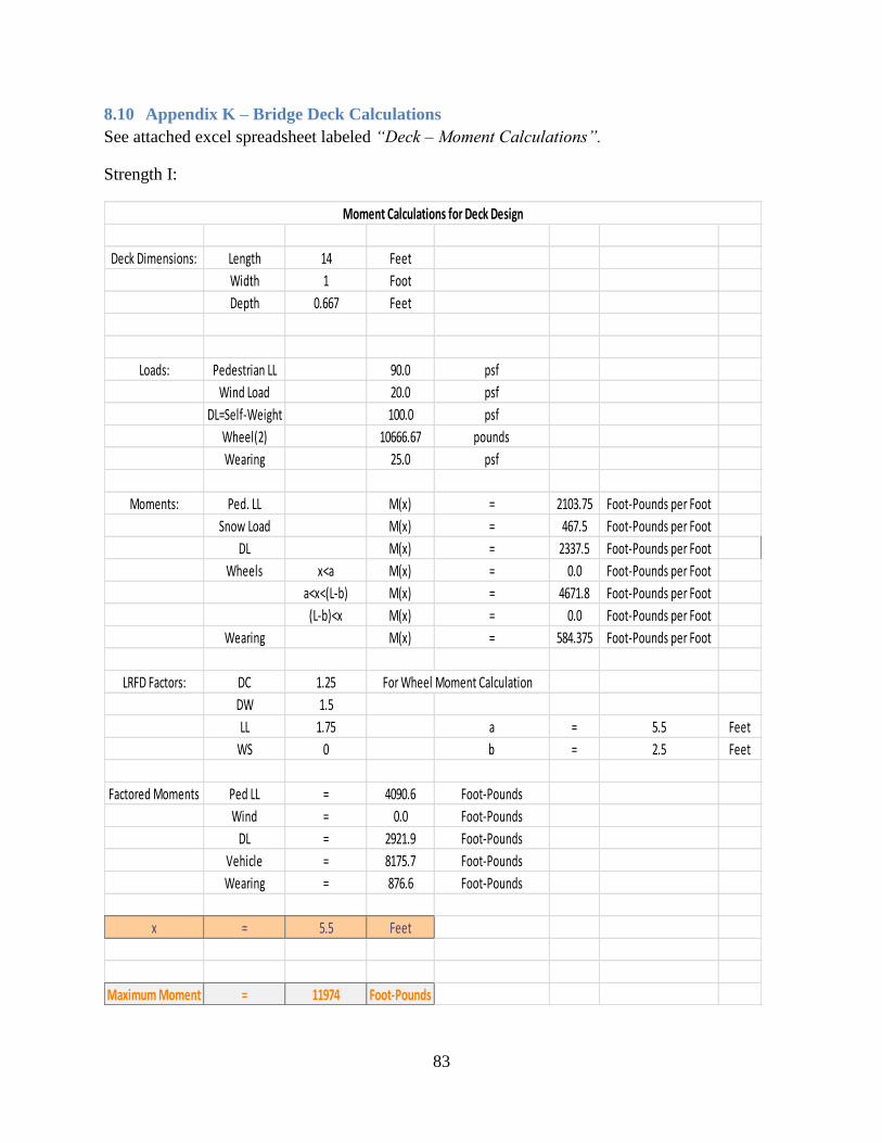
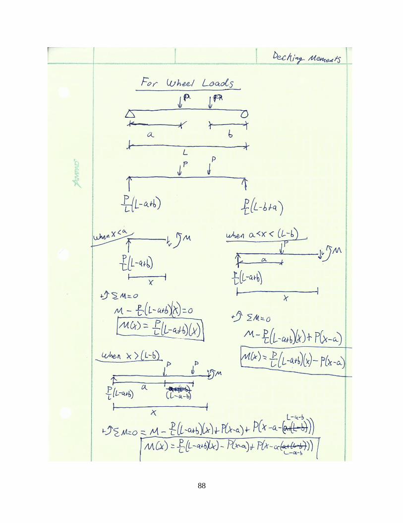
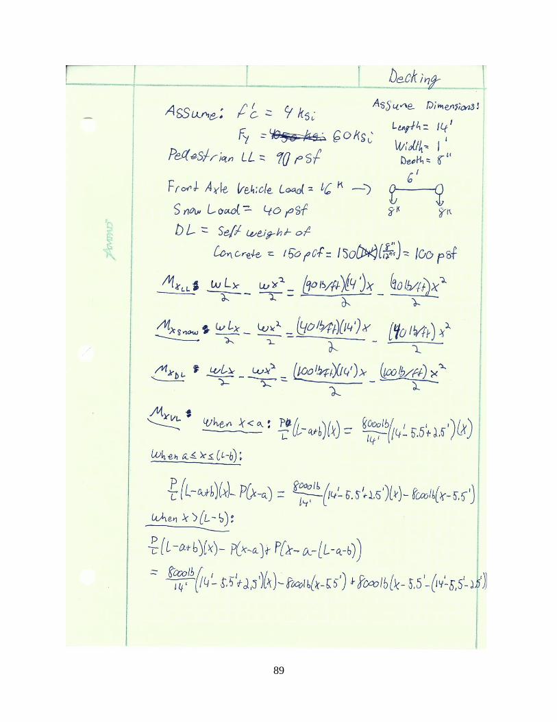
401 Bridge Deck Design
The bridge decking for both options shall be made of a simple cast-in-place concrete deck This
is largely due to the fact that a steel based decking would be less cost effective as the cost of steel
is relatively large compare to concrete The bridge decking will be composed of normal weight
concrete (150 pounds per cubic foot frsquoc = 4 ksi) and 5 steel rebar (fy = 60 ksi) The loads
applied to the deck include 90 pounds per square foot for pedestrians 20 pounds per square foot
to accommodate for vertical wind loads 100 pounds per square foot for self-weight two 10667
pound loads to account for the maximum effective distributed weight on each axel of our design
vehicle and 25 pounds per square foot to account for a 2rdquo wearing surface to go on top of the
decking The vehicle weight distribution was calculated according to Article 46213 of
AASHTO which states that the distribution width for positive moment is (26 + 66 S) in where S
is spacing in feet The maximum moment produced by the vehicle was found using Table 3-23
case 10 of the AISC Steel Construction Manual The shear and moment diagrams from this case
can be seen in Figure 29
Figure 29AISC Table 3-23 Case 10
31
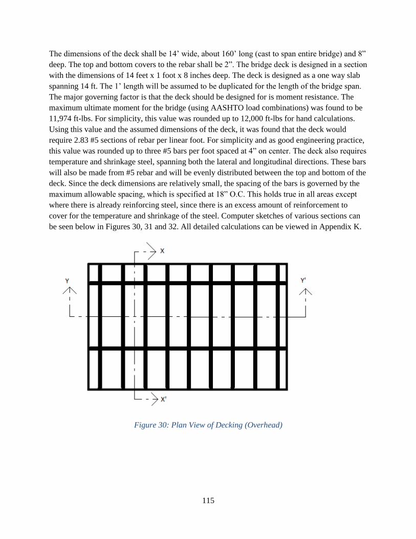
The dimensions of the deck shall be 14rsquo wide about 160rsquo long (cast to span entire bridge) and 8rdquo
deep The top and bottom covers to the rebar shall be 2rdquo The bridge deck is designed in a section
with the dimensions of 14 feet x 1 foot x 8 inches deep The deck is designed as a one way slab
spanning 14 ft The 1rsquo length will be assumed to be duplicated for the length of the bridge span
The major governing factor is that the deck should be designed for is moment resistance The
maximum ultimate moment for the bridge (using AASHTO load combinations) was found to be
11974 ft-lbs For simplicity this value was rounded up to 12000 ft-lbs for hand calculations
Using this value and the assumed dimensions of the deck it was found that the deck would
require 283 5 sections of rebar per linear foot For simplicity and as good engineering practice
this value was rounded up to three 5 bars per foot spaced at 4rdquo on center The deck also requires
temperature and shrinkage steel spanning both the lateral and longitudinal directions These bars
will also be made from 5 rebar and will be evenly distributed between the top and bottom of the
deck Since the deck dimensions are relatively small the spacing of the bars is governed by the
maximum allowable spacing which is specified at 18rdquo OC This holds true in all areas except
where there is already reinforcing steel since there is an excess amount of reinforcement to
cover for the temperature and shrinkage of the steel Computer sketches of various sections can
be seen below in Figures 30 31 and 32 All detailed calculations can be viewed in Appendix K
Figure 30 Plan View of Decking (Overhead)
5 bars
18rdquo OC
5 bars
4rdquo OC
32
Figure 31 Cross-Sectional View of Decking in Y-Yrsquo Direction
Figure 32 Cross-Sectional View of Decking in X-Xrsquo Direction
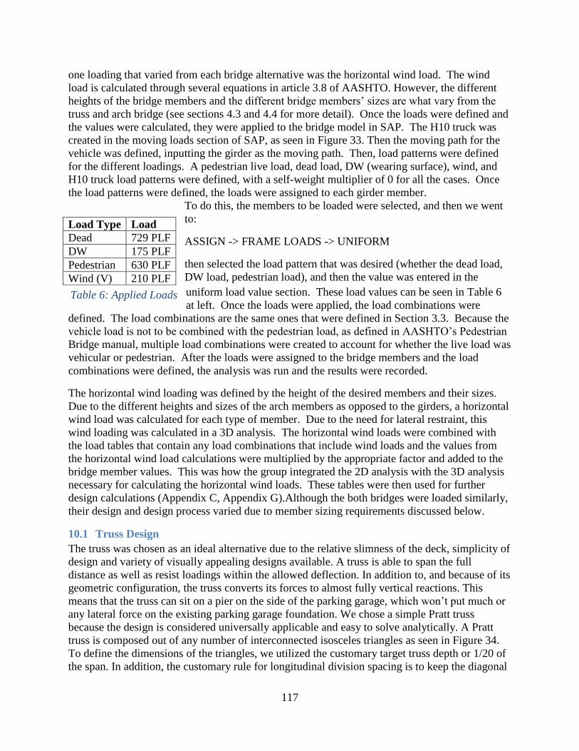
402 Bridge Load and Member Sizing
The bridge design is required to comply with the loadings set forth through AASHTO as
previously discussed in Section 33 Additionally a uniform dead load of 29lbslinear foot was
applied to account for the weight of the railings (Handi-Ramp 2013) Finally a uniformly
distributed dead load was applied to account for the weight of the wearing surface Multiple
sources revealed that a 2rdquo thick concrete wearing surface is ideal for pedestrian bridges (Chen
2003 Works 2011) Due to the limitations of our version of SAP 2000 (educational version)
surface areas could not be loaded Instead the bridges were analyzed in 2D To account for this
problem the bridge was loaded with a uniform dead load to account for the weight of the
concrete slab which was calculated with the following formula
(150 pcf) 812rsquo (deck thickness) 7rsquo (tributary width of each bridge girder)
A similar process was used to account for the wearing surface Since we evenly spaced floor
members connection the sides of the truss and the arches respectively at 14rsquo the pedestrian live
load and vertical wind load were all multiplied by 7rsquo to account for the tributary area that each
floor member would support The vehicle load was run along the girder AASHTO allows for
the load to be distributed via a factor due to moment redistribution through the bridge deck to
both bridge girders AASHTO calculates this redistribution factor through the Lever Rule shown
in Section 41 The live load was then multiplied by this factor in each load combination The
33
one loading that varied from each bridge alternative was the horizontal wind load The wind
load is calculated through several equations in article 38 of AASHTO However the different
heights of the bridge members and the
different bridge membersrsquo sizes are what vary
from the truss and arch bridge (see sections 43
and 44 for more detail) Once the loads were
defined and the values were calculated they
were applied to the bridge model in SAP The
H10 truck was created in the moving loads
section of SAP as seen in Figure 33 Then the
moving path for the vehicle was defined
inputting the girder as the moving path Then
load patterns were defined for the different
loadings A pedestrian live load dead load
DW (wearing surface) wind and H10 truck
load patterns were defined with a self-weight
multiplier of 0 for all the cases Once the load patterns were defined the loads were assigned to
each girder member
To do this the members to be loaded were selected and then we went
to
ASSIGN -gt FRAME LOADS -gt UNIFORM
then selected the load pattern that was desired (whether the dead load
DW load pedestrian load) and then the value was entered in the
uniform load value section These load values can be seen in Table 6
at left Once the loads were applied the load combinations were
defined The load combinations are the same ones that were defined in Section 33 Because the
vehicle load is not to be combined with the pedestrian load as defined in AASHTOrsquos Pedestrian
Bridge manual multiple load combinations were created to account for whether the live load was
vehicular or pedestrian After the loads were assigned to the bridge members and the load
combinations were defined the analysis was run and the results were recorded
The horizontal wind loading was defined by the height of the desired members and their sizes
Due to the different heights and sizes of the arch members as opposed to the girders a horizontal
wind load was calculated for each type of member Due to the need for lateral restraint this
wind loading was calculated in a 3D analysis The horizontal wind loads were combined with
the load tables that contain any load combinations that include wind loads and the values from
the horizontal wind load calculations were multiplied by the appropriate factor and added to the
bridge member values This was how the group integrated the 2D analysis with the 3D analysis
necessary for calculating the horizontal wind loads These tables were then used for further
design calculations (Appendix C Appendix G)Although the both bridges were loaded similarly
their design and design process varied due to member sizing requirements discussed below
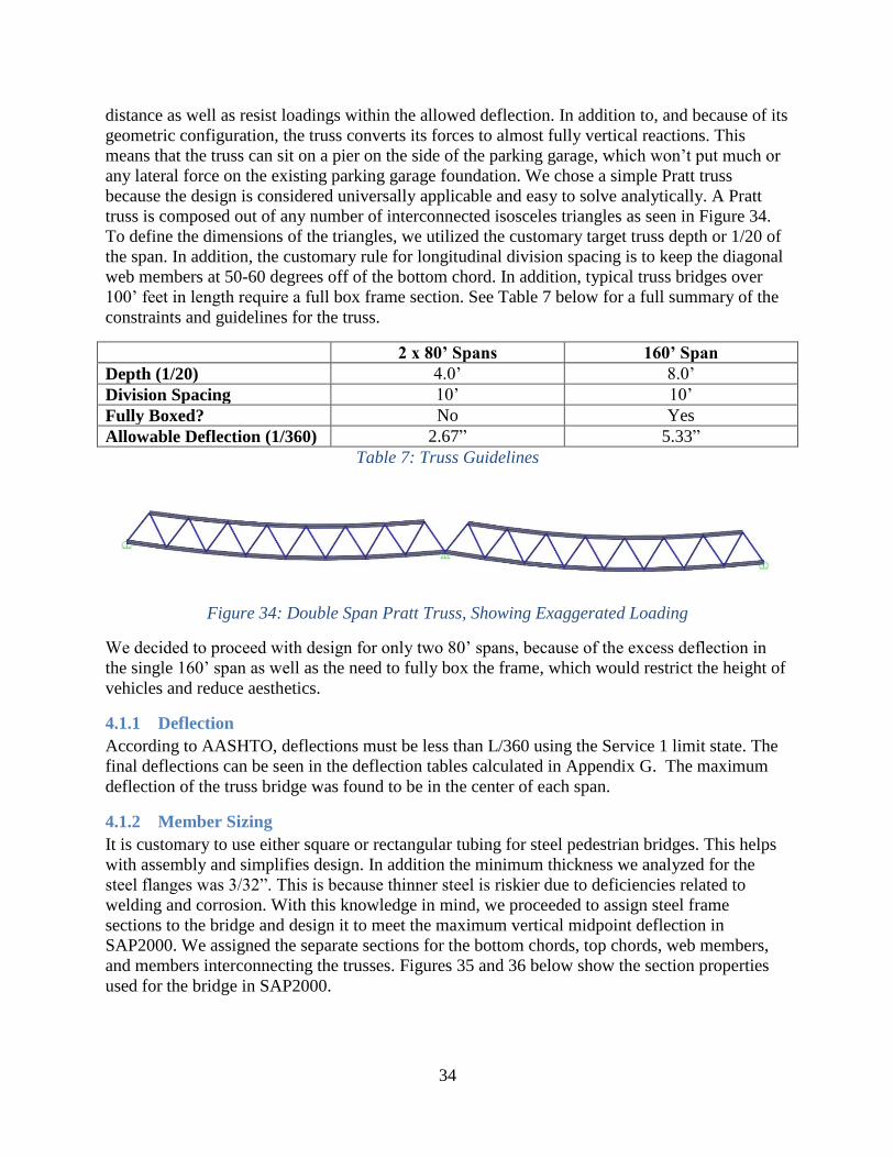
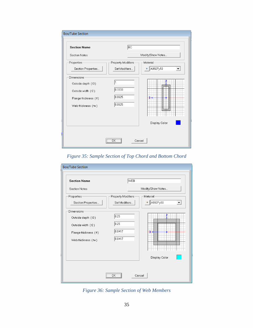
41 Truss Design
The truss was chosen as an ideal alternative due to the relative slimness of the deck simplicity of
design and variety of visually appealing designs available A truss is able to span the full
Load Type Load
Dead 729 PLF
DW 175 PLF
Pedestrian 630 PLF
Wind (V) 210 PLF
Table 6 Applied Loads
Figure 33 Vehicle Load as defined in SAP2000
34
distance as well as resist loadings within the allowed deflection In addition to and because of its
geometric configuration the truss converts its forces to almost fully vertical reactions This
means that the truss can sit on a pier on the side of the parking garage which wonrsquot put much or
any lateral force on the existing parking garage foundation We chose a simple Pratt truss
because the design is considered universally applicable and easy to solve analytically A Pratt
truss is composed out of any number of interconnected isosceles triangles as seen in Figure 34
To define the dimensions of the triangles we utilized the customary target truss depth or 120 of
the span In addition the customary rule for longitudinal division spacing is to keep the diagonal
web members at 50-60 degrees off of the bottom chord In addition typical truss bridges over
100rsquo feet in length require a full box frame section See Table 7 below for a full summary of the
constraints and guidelines for the truss
2 x 80rsquo Spans 160rsquo Span
Depth (120) 40rsquo 80rsquo
Division Spacing 10rsquo 10rsquo
Fully Boxed No Yes
Allowable Deflection (1360) 267rdquo 533rdquo
Table 7 Truss Guidelines
Figure 34 Double Span Pratt Truss Showing Exaggerated Loading
We decided to proceed with design for only two 80rsquo spans because of the excess deflection in
the single 160rsquo span as well as the need to fully box the frame which would restrict the height of
vehicles and reduce aesthetics
411 Deflection
According to AASHTO deflections must be less than L360 using the Service 1 limit state The
final deflections can be seen in the deflection tables calculated in Appendix G The maximum
deflection of the truss bridge was found to be in the center of each span
412 Member Sizing
It is customary to use either square or rectangular tubing for steel pedestrian bridges This helps
with assembly and simplifies design In addition the minimum thickness we analyzed for the
steel flanges was 332rdquo This is because thinner steel is riskier due to deficiencies related to
welding and corrosion With this knowledge in mind we proceeded to assign steel frame
sections to the bridge and design it to meet the maximum vertical midpoint deflection in
SAP2000 We assigned the separate sections for the bottom chords top chords web members
and members interconnecting the trusses Figures 35 and 36 below show the section properties
used for the bridge in SAP2000
35
Figure 35 Sample Section of Top Chord and Bottom Chord
Figure 36 Sample Section of Web Members
36
These four different member sections were analyzed on both bridge lengths to produce the
maximum allowable deflection with the least amount of material It became apparent that we
would need to overbuild the top chord because of the potential of buckling under compression
forces instead of failure in tension In addition we looked into potentially adding member
redundancy so that in the event of one member failing the bridge would not catastrophically fail
It became apparent that this would be far too costly In addition we decided to overbuild for
lateral stability We added diagonal cross members between both the bottom chords and top
chord where applicable Since these members are relatively small they do not add very much to
the weight and cost and yet provide a potential brace against wind and seismic loads The
member sizes were later evaluated in Microsoft Excel to ensure that the maximum allowable
load is not exceeded by the maximum possible load All results and calculations from SAP2000
can be seen in Appendix G
413 Truss Connections
Almost all prefabricated steel trusses utilize welded connections It is very uncommon to use
bolted connections except in the case where a truss comes in multiple sections which are then
bolted together Typically almost all of the welding is done in the factory where the truss is
fabricated and very little welding is done on site See Figures 37 and 38 below for details of
typical truss welds
Figure 37 Typical Tube Cut Prepared for Welding
37
Figure 38 Typical Welded steel Connection
42 Arch Design
The second alternative chosen for analysis was the arch bridge The arch bridge allowed for a
slim deck and allows for a more aesthetically appealing design With the limitation of the
parking garage to support any more loadings the arch has to start below the bridge deck far
enough away from the parking garage as to provide enough space for an adequate foundation
that will not put extra lateral forces on the parking garage structurefoundation The main
concern with the arch bridge is whether or not the arch will provide enough clearance to meet
fire code Because it is desirable that the bridge does not overshadow the parking garage the
height of the bridge was selected to be roughly the same height as the parking garage elevator
shaft
421 Deflection
According to AASHTO deflections must be less than L360 using the Service 1 limit state
Because the bridge is 160rsquo in length the deflections were limited to 44 feet or 533 inches The
final deflections can be seen in the deflection tables in Appendix D ndash Arch Bridge Deflection
Tables The maximum deflection of the arch bridge was found to be in the 20rsquo section of the
bridge located between the left arch and the left bridge deck end which is the section of the
bridge that is essentially simply-supported This section was primarily dependent on the girder
size The maximum deflection recorded between the girder and the arch members was roughly
225 inches well within the deflection limits required from AASHTO
38
422 Member Sizing
The arch bridge was designed in SAP2000 with cross bracings for the girder and arch initially
designed at 10 foot spacing and with a reduced size The cross beams for the girders were
designed as S 5x10 members and the cross beams for the arch were designed as HSS 5x5
members based off of a
maximum deflection The
appropriate load combinations
were applied to each member
(their calculation can be viewed
in 83Appendix D ndash Arch Bridge
D) In all loading cases tables
were exported from SAP2000 to
excel which can be seen in
Appendix C ndash Arch Bridge
Analysis Tables from SAP2000
Once in excel MAX and MIN
equations were created to
calculate the maximum and minimum P V M and S11 (stress) values for each bridge member
Then a summary table was created to calculate the maximum and minimum of the previously
mentioned values for each load case
The arches of the arch bridge were determined to be steel tubes Although concrete is preferred
in compression steel ribs produce far less dead load forces which is ideal due to the limitation
of the parking garage to carry additional stresses Furthermore the steel arches allow for smaller
cross-sections which help with the clearance limitation of the bridge and are popular in arch
bridge design (HSS) In SAP2000 the arches were determined to be located 10rsquo from the
parking garage and 20rsquo from the
loading dock behind Harrington
Auditorium This location was
determined considering the
anticipated size of the foundation
and to allow for the surrounding
buildings to be independent of
the forces experienced in the
foundations of the arches The
steel arches were originally
determined to be 2rsquo wide with a 6rdquo
thick wall and were reduced to
125rdquo wide with a 625rdquo thick wall once the stresses deflections and buckling checks were
calculated following the application and analysis of the load combinations The members were
drawn in SAP using the draw curved frame member tool The height of the bridge was set 20rsquo
above the garage connection height (20rsquo above the 536-7rdquo elevation) and it was set at the middle
of the archrsquos span (not the bridgersquos span) to allow for some symmetry for the arch Once
determining the coordinates for the top of the arch the box for curve type we selected
ldquoParabolic Arch ndash 3rd
Point Coordinatesrdquo to set the height The arch was drawn into SAP
however due to the educational version of SAP2000rsquos limitations the curved member drawn
Figure 40 Cross Section of Arch Member (HSS 125x625)
Figure 30Cross Section of Girder (W10x68)
39
was converted into 13 straight line members To facilitate cable placement the curved frame
memberrsquos location information was exported into Microsoft Excel displaying the frames as
separate straight frame members as shown below in Figure 39 The frame members still act as
an arch however the limitation of SAP2000 was resolved and allowed for a more realistic and
accurate analysis allowing for the ability to manufacture similar smaller members as opposed to
two large arched members The connections for the 13 separate frame members also will serve
as the joints where the cables would transfer the bridge deck loads to the arch Cross members
were added between the two arches to provide lateral support as well as connectivity Finally
the arch members were checked via hand calculations to ensure that buckling does not occur in
these members and to validate the calculations made by SAP2000
Because the design moments were calculated through SAP2000 the bridge had to be ldquobuiltrdquo
before the load cases could be run and the moments determined Therefore the size of the
bridge girders needed to be assumed prior to the design and adjusted accordingly once the
moments were calculated Due to the necessity for the bridge to meet fire code minimum
clearance and the already limited clearance due to the site conditions a W8X48 steel beam was
chosen as the initial girder size through a basic moment calculation considering the pedestrian
live load dead load of the concrete deck The girders were drawn using the drawn frame tool in
SAP2000 The ends of which were determined through the construction documents and the
survey data as mentioned in sections 31 and 32 As the moments and stresses were determined
the girder size was adjusted to comply with AASHTO requirements (AASHTO 2012) The
major factor for the girders was the high stress experienced right at the point of connection
between the girder and the arch (near the loading dock at Harrington Auditorium) The girder
size was increased to a W10X68 to account for the high stress and comply with the bridge girder
calculations (see Appendix E ndash Arch Bridge Design Calculations for more information)
In SAP2000 the cable members were design using the diameter option starting with a diameter
of 25rsquo The sizes of the members were changed as SAP analysis was conducted This option
allowed the cable members to only support tensile forces since cables cannot support
compression Because the arch members were already defined the same grid was used to create
the cable members To connect the cables to the girders the cables were drawn in extending
straight past the deck to a z value of 0 Then the girder and the cables were selected and the
divide cables tool was used to divide the members at their intersections Then the cable
members that extended below the deckgirders were simply deleted leaving the remaining cable
Figure 41 Arch Member As Drawn In SAP2000
40
members in their desired locations (between the arch frame connections and the bridge
deckgirders The final cable layout is shown below in Figure 39
423 Arch Connections
Commonly in the North-Eastern parts on the United States these connection details are left to
the fabricating firm Once the fabricator creates a design for these connections heshe shall
create engineering sketches with design details for approval by the structural designer(s) The
connections that need to be addressed include arch to cable cable to girder and arch to
foundation These connections would likely be similar to those seen in Figures 43 44 and 45
Figure 43 Example of Arch-Cable Connections
Figure 42 Final Cable Layout Designed in SAP2000
41
Figure 44 Example of Cable-Girder Connection
Figure 45 Example of Arch-Foundation Connection
424 Fire truck Clearance
As stated in the bridge requirements the bridge must be able to allow a fire truck to pass beneath
it According to the construction documents the ground elevation is 522rsquo at the parking garage
and about 523rsquo at 50rsquo off the parking garage This means that assuming an even slope every ten
42
feet the ground elevation rises 2rsquo In Figure the height of the fire truck can be observed as
135rsquo as determined in the fire code Taking into account the previous information the bottom
of the bridge must have an elevation of 533-35rdquo at 40rsquo off the parking garage and 533rsquo-6rdquo at 50rsquo
off the parking garage According to the heights in SAP the top of the bridge is at 538rsquo-12rdquo at
40rsquo off the parking garage and 538rsquo-35rdquo at 50rsquo off the parking garage which yields a clearance
of 151rsquo and 152rsquo respectively (observed in Figure ) Taking into account the 8rdquo thick deck and
the 10rdquo outside to outside height of the girder 15rsquo must be taken off the 151rsquo and 152rsquo
measurements Thus the bottom of the deck has a clearance of 136rsquo and 137rsquo at 40rsquo and 50rsquo off
the parking garage respectively Although the bridge does have the capacity to clear a fire truck
having the deck overlap the bridge girders and not simply sit on top of the girders yielding a
greater clearance
Figure 46 Fire Truck Height Dimension
43
43 Foundation Design
The foundation design was completed by hand calculations in Microsoft Excel and specific to
each bridge as seen in the below sections
431 Truss Pier Design
The piers were designed using the vertical reactions of 387kips per end of the bridge applied to
the SAP2000 bridge model seen in Appendix I The supports for each of the four piers which
will hold the decking at the ends of the bridge are to be designed from concrete using a design
compressive strength of 4000 psi and yield strength of the reinforcing steel of 60000 psi By
using the reactions from the concrete decking and self-weight of the truss design steps were
taken into design the concrete piers with steel reinforcement shown in Appendix J The final
recommended design would be a concrete pier 1rsquo x 1rsquo x 5rsquo with a footing of 25rsquo x 25rsquo x 1rsquo
with 5 7 rebar as steel reinforcement typical on center for each side of the footing The
concrete decking will rest on the four concrete piers at the ends of the parking garage
Figure 47 Top of Bridge Deck Clearance
44
Figure 31 Pier near Harrington and Parking Garage Top View
Figure 32 Pier near Harrington and Parking Garage Longitudinal View
45
432 Truss Middle Pier
The single middle pier was designed using the 387kip vertical reaction applied from the
SAP2000 truss bridge model The support for the middle pier which will support the truss bridge
are designed from concrete using a design compressive strength of 4000 psi and yield strength of
the reinforcing steel of 60000 psi By using the reactions from the concrete decking and self-
weight of the truss steps were taken into designing the concrete piers with steel reinforcement
shown in Appendix J The final recommended design would be a concrete pier 2rsquo x 2rsquo x 10rsquo with
a footing of 525rsquo x 525rsquo x 125rsquo with 7 7 rebar as steel reinforcement on center for the middle
concrete pier that will support the concrete decking at the center of the bridge decking An
important issue to note was to have clearance for a fire truck to pass through under the bridge in
case of an emergency the water retention tanks will have to be removed in order to have this pier
constructed with a foundation Pile caps were not necessary as soils consisting of glacial till or
bedrock deposits were found generally less than 8 feet below the surface where the middle pier
would be built these soils had an allowable bearing capacity of 8000 pounds per square foot
Piles would be required if the bearing capacity of the upper soil layers were insufficient but
firmer soils were available at greater depths requiring the use of pile caps Please see Appendix J
for further calculations
Figure 50 Truss Middle Pier Top View
46
Figure 51 Truss Middle Pier Longitudinal Side View
433 Arch Footing Design
The abutments were designed as retaining walls using the loads applied to the SAP2000
bridge model for an Arch The supports for each of the two piers which will support the truss
bridge are to be designed from concrete using a design compressive strength of 4000 By using
the reactions from the concrete decking and self-weight of the truss steps were taken into
designing the abutments shown in Appendix F The final recommended designs will have four
concrete abutments with dimensions shown in Figure 52 4rsquo below grade for support
47
Figure 52 Arch Bridge Abutment Side View
Figure 53 Arch Bridge Abutment Front View
Figure 54 Arch Bridge with Abutments
3ft
8ft
2ft
3ft
3ft
48
5 Results
50 BIM
We attempted to import the models from Sap2000 into REVIT via an IFC file extension
Unfortunately the conversion does not keep the member sections intact and assigns a general
section to all members which resulting in needing to design each member size in REVIT and
assign them to each member accordingly In addition since we were using 2-dimensional frames
the frames had to be duplicated and the deck and cross members had to be constructed as well
We used the design data to form the piers and footings and placed them accordingly We had
difficulty getting the arch to display properly in 3D because the individual members would not
properly connect We eventually solved this problem with the use of a special tool for integrating
the ends of members
The prospect of producing a full ldquowalkablerdquo 3-dimensional model proved too difficult and time
consuming We resultantly settled for producing high quality renders from various camera angles
on both the arch and truss bridge and superimposing them on top of pictures taken from the site
via Adobe Photoshop We finished by touching up the renderings in Adobe Photoshop to suit the
lighting and match more naturally The final renders for the truss and arch can be seen below in
Figures 55 and 56 An outline of the steps taken in the process can be seen in Appendix O
Figure 55 BIM Render of Proposed Truss Bridge
49
Figure 56 BIM Render of Proposed Arch Bridge
51 Schedule
In order to produce a schedule of the two bridge alternatives Primavera software was utilized
Each task in order to construct each bridge was defined from the procurement of the materials to
the excavation of the footings to the end of construction Once each task was identified the
duration of each task was determined The RS Means books were utilized to determine each
taskrsquos duration RS Means has a daily output parameter associated with any item included in the
book For example RS Means lists the daily output of 12rdquo x 12rdquo square columns as 149850
Cubic Yards Knowing the daily output of each task the total amount utilized in each bridge
was determined and compared to the daily output thus determining the duration of each task
Once this step was completed the relationship each task has with each other was determined
For example the columns cannot be constructed before the footings are constructed and have
time to reach an appropriate strength (the footings do not need to necessarily reach their 28 day
strength before the columns are constructed) The predecessor and successor for each task was
determined and once complete the scheduling analysis was run to construct a Gantt chart and
determine the total length of each bridge The Gantt chart for each bridge can be observed in
Figure 57 and Figure 58 The schedules focus on the construction of the bridge taking into
account the procurement of the concrete and steel members
50
52 Cost
RS Means has several books that contain cost data for construction projects In particular the
Building Construction and Heavy Construction Cost Data book set was used to gather cost
information and compile a cost spreadsheet for each bridge These spreadsheets can be viewed
in detail in Appendix L ndash Bridge Cost Estimation Although most of the information needed to
estimate the bridge costs was readily available in the RS Means Cost Data books several
assumptions were used RS Means does not have any cost information on HSS members
therefore the team used a unit price of $2000 per ton which was a number recommended to the
Figure 57 Arch Bridge Gantt Chart
Figure 58 Truss Bridge Gantt chart
51
team by its advisor Guillermo Salazar and was a number that was observed when an online
check of steel prices was conducted Furthermore the team marked up the costs of the arch
members by 10 to account for the increased difficulty of constructing the members as opposed
to constructing mass produced members Also because custom members were used for the
construction of the truss a 33 mark-up was applied to their cost In addition to the
construction cost bonds insurance premiums buildings permit costs and contingencymark-ups
were added to the total cost to account for the total construction cost of the project As a result
of the cost estimation the arch bridge was estimated to cost $228006 and the truss bridge was
estimated to cost $233176 The similarity in price allows the price to not govern in the bridge
selection These costs do not include any related site work which could prove to be a significant
sum (a difference of $5000) All detailed cost estimations can be viewed in Appendices K and L
for the bridges and deck respectively In addition all detailed scheduling information can be
viewed in Appendices M and N for the arch bridge and the truss bridge respectively
THE REMAINDER OF THIS PAGE WAS LEFT INTENTIONALLY BLANK
52
6 Conclusions and Recommendations
60 Conclusions
This project has given our group a greater understanding of the effort time and diligence
required during a major design process Our team took the time to meet with a key administrator
to gain a better understand of why a bridge was necessary The bridge will become a main
gateway at WPI and become part of the future promenade in that location Another broader
implication of the bridge is to improve handicap access to the campus A handicapped individual
could theoretically take the garage elevator to the garage roof and then simply cross the bridge
Once the need for the bridge was addressed research on multiple bridge styles and materials to
give ourselves a number of options to choose from was performed After brief analysis and
design considerations of these options two alternatives were selected for detailed design These
two alternatives would be an arch-cable bridge and a truss bridge
Once these two options were selected we performed an in-depth design and analysis of both
options Using computer modeling in SAP2000 and hand calculations in Microsoft Excel most
major aspects of the bridges were designed The key components designed included the bridge
deck the bridge superstructure the bridge substructure and the foundation These components
were addressed for both bridges During the design of each bridge key codes had to be followed
to ensure the safety and integrity of the bridge Chief among these codes for design were those
set down by the American Association of State Highway and Transportation Officials
(AASHTO)
Once the comprehensive design of each bridge was completed an in depth schedule and cost
estimate could be produced for each alternative Based on our analysis each bridge would have
similar costs and times required for construction Due to this a final decision would likely be
made based on constructability aesthetics and the overall favoritism of the Board of Trustee at
Worcester Polytechnic Institute Please see Section 61 for further recommendations regarding
our expertise in the matter
Exploring the social and technical aspects of this project has broadened our views of the
construction process Understanding that we need not only design the bridge but also design a
bridge that will actually get built has been a challenge
61 Recommendations
We fully recommend both the two-span truss and the single-span arch as viable alternatives
With similar estimated prices materials and foundation designs it comes down to some smaller
choices when making a decision
53
Constructability
The truss would be a more easily and quickly constructible bridge because it would most likely
be prefabricated and then simply lifted into place which could be done in a single week
Conversely the arch would need to be assemble in sections which would take far longer and
would require significant temporary shoring and possible the use of multiple cranes
Aesthetics
In general we think that the arch would be a more attractive design for that particular spot on
campus But we do consent that this category can be very subjective
Foundation Designs
The truss would require a middle pier unlike the arch Pacing a middle pier would disrupt the
storm water infiltration pipes set below the proposed bridge location This could affect the
drainage capacity of the site
611 Further Steps
1) Present the BIM renderings to the WPI facilities staff for feedback
2) Present the BIM renderings cost and schedule information to WPIrsquos board of trustees for
funding
3) If approved for funding solicit bids for the project
4) Select a bid and schedule construction in accordance with the guidelines listed in this
report
THE REMAINDER OF THIS PAGE WAS LEFT INTENTIONALLY BLANK
54
7 Bibliography
AASHTO (2009) LRFD Guide Specifications for Design of Pedestrian Bridges New York AASHTO
AASHTO (2012) AASHTO LRFD Bridge Design Specifications Washington DC AASHTO
Alliance M D (2000) Product selection guide FRP composite products for bridge applications New
York Market Development Alliance
ASCE (2001) Report Card for Americas Infrastructure Washington American Society of Civil
Engineers
AVK (2010) Sustainability of Fiber-Reinforced Plastics An Assessment Based on Selected Examples of
Application Frankfurt AVK
Azamejad A McWhinnie K Tadros G amp Jiri a S (2011) Cable-Stayed Bridge as an Alternative for
Medium and Short Span Bridges 2011 Annual Conference of the Transportation Association of
Canada Edmonton Alberta Transportation Association of Canada
Azar J M (1991) Structural components in Highway Bridge Deck Applications New York VCH
Publishers
Chen W F (2003) Bridge Engineering Handbook Boca Raton FL CRC Press LLC
Colorado Department of Transportation (2010) 2010 Cost Data Colorado Department of Transportation
Department of Justice (2010) 2010 ADA Standards for Accesible Design Washington DC Department
of Justice
Godden W G (Ed) (1997) Cable-Stayed With Steel Deck (University of California Berkeley)
Retrieved from National Information Service for Earthquake Engineering
httpniseeberkeleyeduleonhardthtmlcable-stayed_with_steel_deckhtml
Handi-Ramp (2013) ADA Compliant Handrails amp Railings Retrieved from Handi-Ramp Handrails
httpwwwhandirampcomhandrailshtm
Harvey W J (1993) A Reinforced Plastic Footbridge Alberfeldy UK Structural Engineering
International
Henry J (1985) Deck Girders System for Highway Bridges Using Fiber Reinforced Plastics 1985
North Carolina State University
Howe A (2012 Spring) Delta Ponds Pedestrian Bridge Extending a Sustainable Transportation
Network Aspire pp 20-23
johnweekscombridgespagesms19html (2013 february 3) Retrieved from johnweekscom
johnweekscombridgespagesms19html
Malvar T A (2005) Fiber-Reinforced Polymer Composites in Bridges A State-Of-The-Art Report Port
Hueneme California NAFAC
55
Management D o (2011) 2011 WPI Student Fact Book Worcester
Market Development Alliance of the FRP Composites Industry (2004) Bridge Product Gateway
Retrieved from American Composites Manufacturers Association
httpwwwmdacompositesorgmdapsgbridge_pedestrian_printhtml
Podolny Jr W P (nd) Construction and Design of Cable-Stayed Bridges (2 ed) New York John
Wiley amp Sons
Rayor G P (2010) I-5 Beltline (Gateway) Pedestrian Bridge Bridge Design Conference Oregon
Department of Transportation
RS Means (2011) RS Means Building Construction Cost Data 2012 Norwell MA RS Means Co Inc
RS Means (2011) RS Means Heavy Construction Cost Data 2012 Norwell MA RS Means Co Inc
The Associated Press (2006 July 5) Judge rules against fans in Lowes birdge collapse Retrieved
October 10 2012 from ESPN
httpsportsespngocomrpmnewsstoryseriesId=2ampid=2510428
USDA (2011) A Guide to Fiber-Reinforced Polymer Trail Bridges Washington DC United States
Department of Agriculture
Works C C (2011) Cuyahoga County engineer Supplement to the 2007 ODOT Bridge Design Manual
Cuyahoga Cuyahoga County of Public Works
Zhou A (2002) Stiffness and Stregnth of Fiber Reinforced Polymer Composite Bridge Deck Systems
Blacksburg Virginia Polytechnic Institute and State University
56
8 Appendices
80 Appendix A ndash Survey Data
81 Appendix B ndash Interview Transcript
Interview with Fred DiMauro Head of Facilities September 12 2012 9 AM Kazin Room
Have 3 projects coming together at same time
Rec Center stand alone
Garage came sooner than expected
Covered stairs and canopy main pedestrian walk way to campus
Other access ways depend on how Dana Harmon allows access into building
Going Around Building
When project is complete must have passage way for all types of people (handicapped or not)
With creation of garage majority of people will be accessing main campus from it
Handicap issuesmdashseries of ramps from Parking Garage to Campus Center
Athletic field will become an extension of campus with Pedestrian Bridge (elevator in Parking
Garage)
Quad to Higgins Gardens
Further complications ndash Fire truck underneath bridge (Height of bridge with Parking Garage)
Challenge of Building Bridge
DiMauro has agreed to go forward with Bridge Design Firm
Description
Distance
(ft)
Elevation
(ft)
Horizontal
Distance Angle Angle
0 Angle
Adjustment
1 Benchmark 185299 -139 2323745 2326291667 0
2 Garage Floor 47068 -1292 2160539 2160941667 1654
3 Left Opening (G) 38692 13274 3791726847 1981511 1982530556 3437611111
4
Right Opening
(G) 47722 13069 4712912351 2151950 2153305556 1729861111
5
Loading Dock
Left 131575 183 1309577326 3385442 3389116667 2537175
6
Loading Dock
Right 128512 18208 1278890734 3310255 3310486111 2615805556
57
Library to Quad to Higgins Gardens Parking Garage and Athletic Field all a connection of
Campus
Storm Water distribution Center
Supports of Bridge will have to coordinated with Manifolds of Stairs
Two issues with vehicles to fields with Athletic Equipment
Two storage rooms for Athletic Equipment
Needs support for snow removal equipment size width load
(Partial solution) ramp comes along side walk
Bridge Vehicle Weight limit
Constraint Financial impact weight
Committed to Length (life of project)
Court level of Harrington
Bridge comes across court level
Promenade will be in bridge design
Halverson Design Partnership
Cost amp Finance
-BP Cost figure in Analysis
1 million dollars for Promenade Bridge and site work
Halverson
Estimate from Gilbane 300000
Preference in Materials amp Lifespan
Steel Precast
Aesthetics are more concerned and character of bridge
Does have to fit in surroundings aesthetically successful but within Budget
Salazar Bridge in Venice modern in antiquity accepted by people
58
Confined
Bridge and Promenade will be built within 2 years of the complete of Parking Garage during
construction will close knuckle And area close 1 entrance
Can obtain soil conditions from Gilbane
Decision process from WPI
President and administration will bring to trustees the rational why itrsquos important Jeff Solomon
(CFO) how much money we have and how to spend it
Trustees receive information why this is a priority see what major project options
Deliverables for this project
What we would do how it looks like
3D image to walk around in
Move around a model in real time
Site plan-Structural Detail
3D rendering in surrounding
Cost estimates
Narrative of Design
Features Strength or Challenges
Scheduling over the summer (still impact on many things)
Conditions at start of A term or if project begins in Spring Conditions at commencement
graduation
Evaluation of those
Question for SMAA was there foundation put in place for bridge for later
59
82 Appendix C ndash Arch Bridge Analysis Tables from SAP2000
Arch Bridge with Members Labeled
Moment Diagram for Strength I (P) [Maximum Moment of All Load Cases]
Load Diagram for Strength I (P) [Maximum Load of All Load Cases]
60
TABLE Strength I (P) Maximum Frame Max P Min P Max V Min V Max M Min M Text Kip Kip Kip Kip Kip-ft Kip-ft
Arch 1 -2542 -2544 -23 -25 3583 444 Arch 2 -2504 -2505 -437 -437 19132 3583 Arch 3 -2028 -2138 169 -25 -1901 -9791 Arch 4 -1944 -2029 68 -163 521 -9791 Arch 5 -1844 -1929 203 -249 2621 -5075 Arch 6 -1844 -1886 203 -100 6164 -1716 Arch 7 -1842 -1906 266 -185 4612 -1934
Arch 8 -1924 -1996 179 -48 2477 -699 Arch 9 -1999 -2117 84 -147 1224 -699
Arch 10 -2102 -2232 -84 -261 3078 -636 Arch 11 -2276 -2277 318 317 18941 -8139 Cable 1 221 221 0 0 0 0 Cable 2 244 244 0 0 0 0 Cable 3 232 232 0 0 0 0 Cable 4 225 225 0 0 0 0 Cable 5 215 215 0 0 0 0 Cable 6 221 221 0 0 0 0 Cable 7 232 232 0 0 0 0 Cable 8 236 236 0 0 0 0
Cable 9 258 258 0 0 0 0 Cable 10 218 218 0 0 0 0 Girder 1 135 128 -84 -320 2025 0 Girder 2 128 120 151 -84 21527 16897 Girder 3 120 113 387 151 16897 -10072 Girder 4 113 109 492 387 -10072 -29716 Girder 5 14 04 140 -148 4284 -7987 Girder 6 -180 -193 13 -388 13201 -18775 Girder 7 -193 -201 249 13 13200 0
61
To see the rest of the tables refer to excel file ldquoArch Bridge Design Calculations and Load
Analysis Load Tablesrdquo and refer to sheet ldquoSummaryrdquo and all succeeding sheets
TABLE
Summary
Frame Max P Min P Max V2 Min V2 Max M3
Text Kip Kip Kip Kip Kip-ft
Arch 10 -25443 3189 -4379 19132
Cable 258 -0113 0204 -020 1089
Girder 280 -2851 4928 -4164 21527
Cross
(G) 0098 -0196 9506 -1789 302
Cross
(A) 0038 -0099 349 -5244 258
Min
M3
Max
Stress
Min
Stress
Max
Stress
Min
Stress
Kip-ft KSF KSF KSI KSI
-
979126 355639 -65584 246 -4554
-4172 474194 0 329 0
-
297166 693209 -67721 481 -4702
-
607285 14795 -15591 1027 -1082
-64111 17799 -18117 1236 -1258
83 Appendix D ndash Arch Bridge Deflection Tables
TABLE Joint
Displacements
Joint Maximum Deflection
Maximum Allowable Deflection
Girder 2197
inches lt 533
inches OK
Arch 1367
inches lt 433
inches OK
Joint R
Text Radians
Arch 1 00019
Arch 2 -000089
Arch 3 -000046
Arch 4 00046
Arch 5 0003319
62
Arch 6 -000017
Arch 7 -000372
Arch 8 -000274
Arch 9 0001416
Arch 10 -000324
Arch 11 000303
Girder 1 0021184
Girder 2 0010312
Girder 3 -000815
Girder 4 -001299
Girder 5 -000286
Girder 6 -001056
Arch-Cable 1 -000336
Arch-Cable 2 0002641
Arch-Cable 3 0005173
Arch-Cable 4 0003422
Arch-Cable 5 0001445
Arch-Cable 6 -000071
Arch-Cable 7 -000378
Arch-Cable 8 -0004
Arch-Cable 9 -000103
Arch-Cable 10 0002239
Girder-Cable 1 -000171
Girder-Cable 2 0002706
Girder-Cable 3 0004743
Girder-Cable 4 0004179
Girder-Cable 5 0001641
Girder-Cable 6 -000146
Girder-Cable 7 -000351
Girder-Cable 8 -000374
Girder-Cable 9 -0002
Girder-Cable 10 0000659
Girder-Arch
Harrington -000517
Girder-Arch Parking
Garage 0001644
Joint U
Text in
Arch 1 0
Arch 1 0
Arch 2 0066
Arch 2 -0006
Arch 3 0102
63
Arch 3 -0356
Arch 4 0312
Arch 4 -0426
Arch 5 0310
Arch 5 -0336
Arch 6 0266
Arch 6 -0346
Arch 7 0347
Arch 7 -0443
Arch 8 0419
Arch 8 -0371
Arch 9 0199
Arch 9 -0099
Arch 10 0221
Arch 10 00368
Arch 11 0
Arch 11 0
Girder 1 0
Girder 1 0
Girder 2 -0034
Girder 2 -0046
Girder 3 -0031
Girder 3 -0050
Girder 4 0
Girder 4 -0017
Girder 5 -0014
Girder 5 -0031
Girder 6 0
Girder 6 0
Arch-Cable 1 0038
Arch-Cable 1 -0217
Arch-Cable 2 0204
Arch-Cable 2 -0416
Arch-Cable 3 0326
Arch-Cable 3 -0418
Arch-Cable 4 0323
Arch-Cable 4 -0353
Arch-Cable 5 0288
Arch-Cable 5 -0340
Arch-Cable 6 0283
Arch-Cable 6 -0380
Arch-Cable 7 0341
Arch-Cable 7 -0440
64
Arch-Cable 8 0411
Arch-Cable 8 -0429
Arch-Cable 9 0356
Arch-Cable 9 -0283
Arch-Cable 10 0118
Arch-Cable 10 -0057
Girder-Cable 1 0012
Girder-Cable 1 0002
Girder-Cable 2 0017
Girder-Cable 2 -0014
Girder-Cable 3 0014
Girder-Cable 3 -0031
Girder-Cable 4 0
Girder-Cable 4 -0040
Girder-Cable 5 -0016
Girder-Cable 5 -0041
Girder-Cable 6 -0005
Girder-Cable 6 -0043
Girder-Cable 7 0010
Girder-Cable 7 -0046
Girder-Cable 8 0021
Girder-Cable 8 -0040
Girder-Cable 9 0021
Girder-Cable 9 -0026
Girder-Cable 10 0011
Girder-Cable 10 -0009
Girder-Arch
Harrington 0009
Girder-Arch
Harrington -0003
Girder-Arch Parking
Garage 0007
Girder-Arch Parking
Garage -0006
84 Appendix E ndash Arch Bridge Design Calculations
See attached excel file labeled ldquoDesign Calculations and Load Analysis Tables ndashArch rdquo and
refer to tabs ldquoArch Calculationsrdquo ldquoCable Calculationsrdquo ldquoGirder Calculationsrdquo ldquoFatigue and
Fracture Limit Statrdquo ldquoStrength Limit Staterdquo ldquoPositive Flexure Composite Sectrdquo ldquoC and NC in
Negative Flexurerdquo ldquoShear Resistancerdquo and ldquoHorizontal Wind Loadingrdquo
85 Appendix F ndash Arch Bridge Foundation Design Calculations
Design of Abutment
65
Calculate Resultant Force R Using Known Fx Fy and Fz values
radic
radic
Known Values
Compressive Strength of Concrete
Allowable Soil Pressure
Concrete Self weight
Based on Soil Type Silty Sand Sand and Gravel with High Clay Content
Soil Pressure
Internal Friction Phi
Friction Coefficient
Using Equations obtain soil pressure coefficients
Optimum Design of Retaining wall is through approximations with reasonable dimensions and
stability checks
Solve for Total Earth Thrust
66
Distance from Base y is equal to Height divided by 3
Solve for Overturning Moment
Calculate Component Weights of Abutment
Find the Component Weights W by multiplying component area times concrete weight
Also find sum of all Component Weights
Find the Restoring Moment by multiplying each Component Weight W by distance X away from
the front edge
Also find the Sum of all Restoring Moments
Solve for the Factor of Safety
X
67
Distance from Resultant front edge A
Maximum Soil Pressure q
[( ( ] (
)
Corresponding Resisting Friction
Passive Pressure
Using Passive Pressure and Friction Force Solve for Factor of Safety against sliding
If Fsliding is greater than 15 then favorable design of Abutment
Recommended Abutment Design
68
Figure 26 Arch Bridge Abutment Side View
Figure 27 Arch Bridge Abutment Front View
Abutment Calculations
R 212207 lb
Divide by Number of Abutments x2 106104 lb
Spread by Length of Abutment
Labut=5ft 21221 lbft
Soil Bearing Coefficients
Phi=30
Kah 033333
Kph 3
w soil Pressure 120 lbft^3
wc Weight of Concrete 150 lbft^3
Total Height H 6 ft
3ft
8ft
2ft
3ft
3ft
69
Back wall
Rectangle
B 2 ft
H 3 ft
Back wall Rectangle Area 6 ft^2
Back wall R-DL 900 lbft
Back wall
Triangle
B 3
H 3
Back wall Triangle Area 45
Back wall T-DL 675 lbft
Footing
Rectangle
B 8
H 3
Footing Area 24
Footing DL 3600 lbft
Soil Pressure
Acting Area
B 3
H 6
Acting Area 18
Soil Pressure 2160 lbft
Table-Acting Loads w x Mr
Back wall R-DL 2100 4 8400
Back wall T-DL 1575 65 102375
Footing DL 3600 6 21600
Soil Pressure 2520 15 3780
Bridge Pressure 21221 5 1061035
Sum R 310157 Sum Mr 150121
y=h3 2
P=12Kawh^2 1870615
Mo Overturning Moment 374123
70
Factor of Safety 4012611
Distance from Resultant Front Edge a 4719538
Max Soil Pressure q1=(4l-
6a)(RvL^2) 1784747 lbft^2
Base Coefficient Friction Factor f 05
Friction Force F 1550785 lb
Minimum Depth Recommended 4 ft
Disregard Depth Due to Environment 15 ft
Considered depth h 25 ft
Passive Pressure
12wh^2Kph 1125 lb
Safety Factor Against Sliding
Fsliding 8891649
gt15 Favorable
Design
86 Appendix G ndash Truss Bridge Analysis Tables from SAP2000
Member Numbers
Member
Maximum Load Output
Case
Axial
load
Axial Capacity
Kip Kip
145 Strength 1 (Pedestrian) 432 471
146 Strength 1 (Pedestrian) 692 726
147 Strength 1 (Pedestrian) 884 903
148 Strength 1 (Pedestrian) 1000 1006
149 Strength 1 (Pedestrian) 958 969
150 Strength 1 (Pedestrian) 772 801
151 Strength 1 (Pedestrian) 417 455
71
Member
Maximum Load Output
Case
Axial
load
Axial Capacity
Kip Kip
152 Strength 1 (Pedestrian) 452 491
153 Strength 1 (Pedestrian) 843 866
154 Strength 1 (Pedestrian) 1065 1991
155 Strength 1 (Pedestrian) 1141 1991
156 Strength 1 (Pedestrian) 1065 1991
157 Strength 1 (Pedestrian) 841 864
158 Strength 1 (Pedestrian) 461 499
159 Strength V (Pedestrian) 548 1991
160 Strength 1 (Pedestrian) 325 462
161 Strength 1 (Pedestrian) 245 305
162 Strength 1 (Pedestrian) 149 187
163 Strength 1 (Pedestrian) 51 124
164 Strength 1 (Pedestrian) 232 265
165 Strength 1 (Pedestrian) 444 1991
166 Strength 1 (Pedestrian) 520 1991
167 Strength 1 (Pedestrian) 572 1991
168 Strength 1 (Pedestrian) 491 1991
169 Strength 1 (Pedestrian) 201 234
170 Strength 1 (Pedestrian) 99 124
171 Strength 1 (Pedestrian) 93 124
172 Strength 1 (Pedestrian) 279 462
173 Strength 1 (Pedestrian) 477 1991
174 Strength 1 (Pedestrian) 573 1991
175 Strength 1 (Pedestrian) 537 2237
176 Strength 1 (Pedestrian) 328 2237
177 Strength 1 (Pedestrian) 235 462
178 Strength 1 (Pedestrian) 145 124
179 Strength 1 (Pedestrian) 56 124
180 Strength 1 (Pedestrian) 236 462
181 Strength 1 (Pedestrian) 447 2237
182 Strength 1 (Pedestrian) 528 2237
183 Strength 1 (Pedestrian) 564 2237
184 Strength 1 (Pedestrian) 488 2237
185 Strength 1 (Pedestrian) 277 462
186 Strength 1 (Pedestrian) 93 199
187 Strength 1 (Pedestrian) 98 199
188 Strength 1 (Pedestrian) 284 296
189 Strength 1 (Pedestrian) 478 2237
72
Member
Maximum Load Output
Case
Axial
load
Axial Capacity
Kip Kip
190 Strength 1 (Pedestrian) 583 2237
193 Strength 1 (Pedestrian) 978 1001
194 Strength 1 (Pedestrian) 981 1004
195 Strength 1 (Pedestrian) 863 895
196 Strength 1 (Pedestrian) 588 632
197 Strength 1 (Pedestrian) 238 269
198 Strength 1 (Pedestrian) 658 700
199 Strength 1 (Pedestrian) 959 984
200 Strength 1 (Pedestrian) 1105 1114
201 Strength 1 (Pedestrian) 1108 1117
202 Strength 1 (Pedestrian) 1104 1113
203 Strength 1 (Pedestrian) 950 976
204 Strength 1 (Pedestrian) 643 686
205 Strength 1 (Pedestrian) 945 971
206 Strength 1 (Pedestrian) 220 250
Girder 1 Strength 1 (Pedestrian) 231 261
Girder 2 Strength 1 (Pedestrian) 794 831
Member
Output Case Moment
Kip-ft
145 Strength 1 (Pedestrian) -12891
146 Strength 1 (Pedestrian) 69299
147 Strength 1 (Pedestrian) 46825
148 Strength 1 (Pedestrian) 79618
149 Strength 1 (Pedestrian) 92879
150 Strength 1 (Pedestrian) 90424
151 Strength 1 (Pedestrian) 71154
152 Strength 1 (Pedestrian) -08219
153 Strength 1 (Pedestrian) 61684
154 Strength 1 (Pedestrian) 89813
155 Strength 1 (Pedestrian) 95181
156 Strength 1 (Pedestrian) 98837
157 Strength 1 (Pedestrian) 94174
158 Strength 1 (Pedestrian) 77447
159 Strength 1 (Pedestrian) 09780
160 Strength 1 (Pedestrian) 05340
73
Member
Output Case Moment
Kip-ft
161 Strength 1 (Pedestrian) 01341
162 Strength 1 (Pedestrian) 04511
163 Strength 1 (Pedestrian) 00163
164 Strength 1 (Pedestrian) -02215
165 Strength 1 (Pedestrian) -03683
166 Strength 1 (Pedestrian) -10980
167 Strength 1 (Pedestrian) -09411
168 Strength 1 (Pedestrian) 10950
169 Strength 1 (Pedestrian) 03976
170 Strength 1 (Pedestrian) 02551
171 Strength 1 (Pedestrian) -00069
172 Strength 1 (Pedestrian) -02660
173 Strength 1 (Pedestrian) -04798
174 Strength 1 (Pedestrian) -08969
175 Strength 1 (Pedestrian) -05184
176 Strength 1 (Pedestrian) -02063
177 Strength 1 (Pedestrian) -04849
178 Strength 1 (Pedestrian) -00245
179 Strength 1 (Pedestrian) 01835
180 Strength 1 (Pedestrian) 03418
181 Strength 1 (Pedestrian) 10381
182 Strength 1 (Pedestrian) -09901
183 Strength 1 (Pedestrian) -11507
184 Strength 1 (Pedestrian) -04211
185 Strength 1 (Pedestrian) -02803
186 Strength 1 (Pedestrian) -00014
187 Strength 1 (Pedestrian) 02454
188 Strength 1 (Pedestrian) 04486
189 Strength 1 (Pedestrian) 08611
190 Strength 1 (Pedestrian) 06324
193 Strength 1 (Pedestrian) -15902
194 Strength 1 (Pedestrian) -117659
195 Strength 1 (Pedestrian) -82303
196 Strength 1 (Pedestrian) -149506
197 Strength 1 (Pedestrian) 86573
198 Strength 1 (Pedestrian) -1108543
199 Strength 1 (Pedestrian) 72503
200 Strength 1 (Pedestrian) -148850
74
Member
Output Case Moment
Kip-ft
201 Strength 1 (Pedestrian) -79897
202 Strength 1 (Pedestrian) -84717
203 Strength 1 (Pedestrian) -79705
204 Strength 1 (Pedestrian) -111702
205 Strength 1 (Pedestrian) -18397
206 Strength 1 (Pedestrian) -40449
Girder 1 Strength 1 (Pedestrian) -09780
Girder 2 Strength 1 (Pedestrian) -187892
87 Appendix H ndash Truss Bridge Deflection Tables
See attached excel spreadsheet labeled ldquoDesign Calculations and Load Analysis Tables ndash Trussrdquo
88 Appendix I ndash Truss Bridge Design Calculations
See attached excel spreadsheet labeled ldquoDesign Calculations and Load Analysis Tables ndash Trussrdquo
89 Appendix J ndash Truss Bridge Foundation Design Calculations
See attached excel spreadsheet labeled ldquoPier - Design Spreadsheetrdquo and ldquoAbutment ndash Design
Spreadsheet See attached word documents ldquoPier ndash Design Equationsrdquo and ldquoAbutment ndash Design
Equationsrdquo
Design of Pier for Harrington Garage and Truss Bridge Middle Pier
Calculate Resultant Force R Using Known Fx Fy and Fz values
radic
radic
Known Values
Compressive Strength of Concrete
Allowable Soil Pressure
Concrete Self weight
75
Soil Pressure
Calculate Effective Bearing Capacity to Carry Column Load
(Minimum Depth Cover for column is 4ft)
Calculate the Area Required
After Calculating Area required solve for a Base b value that will meet the Area required
For Strength Design Upward pressure caused by column load is the Resulstant divided by Base
B
Based on the Base b and A req find a column side length lc and d value
Footing Depth is determined by punching shear on critical perimeter abcd length of critical
perimeter is bo
(
The punching Shear force acting on this perimeter is equal to total upward pressure minus that
acting within the perimeter abcd
( (
)
Corresponding nominal shear strength is Vc
radic (
If design strength exceeds factored shear Vu1 depth value d is adequate for punching shear
The selected value d will now be checked for beam shear
76
(
Nominal shear strength
radic
Design Shear Strength
If design shear strength is larger than factored shear Vu2 then d will be adequate for one-way
shear
Solve for the moment Mu
(
)
Using Mu value the required area of steel is
(
Checking the minimum reinforcement ratios
radic
Steel reinforcement cannot be less than
Selecting an economical Bar such as 7rebar calculate required numbers of rebar and spacing
Calculate height of footer
77
Pier Harrington and Parking Garage Top View
Pier Harrington and Parking Garage Side View
78
Truss Middle Pier Top View
Truss Middle Pier Side View
Calculations
Piers Harrington amp Parking Garage
79
Values
Fx=18287k 49890 lb
Fy=14174k 61000 lb
Fz=3k 3000 lb
Rxy=Sqrt(x^2+y^2) 7880363 lb
R=sqrt(Rxy^2+Z^2) R2 (For Two Piers) 3943036 lb
Soil Conditions
fc=4ksi 400000 lbin^2
Allowable Soil Bearing Capacity q_a=8kft^2 800000 lbft^2
Concrete Self Weight Wc=150lbft^3 15000 lbft^3
Soil Pressure w 12000 lbft^3
Column 12in x 12in 1200 in
Effective Bearing Capacity to Carry Column Service
Load
q_e=(q_a)-(WcxMinimum Cover) 752000 lbft^2
Footing Depth determined by Calculating Punching Shear on Critical Perimeter abcd
A_Req=Rq_e 524 ft^2
Square Root 229
Recommended Square Footing Size B=25 250
Recommend Using a 25ft x 25ft Square Footing 625 ft^2
q_u=Ub 1577214 lbft^2 1577 kft^2
Based on Footing Size and Column Size Recommend
D=13 600 in
Perimeter Bo=4(12+D) 7200 in
Vu1=qu(A-((CL+D)12)^2) 6308857 lb
Available Shear Strength
Vc=4sqrt(fc)(bo)(d) 10928832 lb
phi(Vc)=75Vc 8196624 lb
Va2=qu(9in)(1ft12in)b 7097464 lb
Vc=2sqrt(fc)(b)(12in1ft)(d) 2276840 lb
phi(Vc)=75Vc 1707630 lb
80
Reinforcing Steel Design
fy=60ksi 60000 psi
Mu=qub(a^22)(12inft) 13307745 lb-in 13308 k-in
As=Mu(9fy(d-1) 049 in^2
Asmin=(3sqrt(fy)(fy))(b12)(d) 273 in^2
But no less than
Asmin=200fy(b12)(d) 288 in^2
Use As=152in^2
Using 7 Rebar (Ab=06in^2)x5= 3in2gt 288in2 6
Spacing in horizontal and vertical direction
6in Spacing for 25
ft
Height of Footer
ACI Reommends Minimum of 3 Cover
H=D+151+3 11 in
Use H=12in 12 in
Recommended Final Foot Design be 25ftx25ftx1ft
Column 1ftx1ftx5ft
Pier Truss Bridge Middle Pier
Pier Design Garage Values
Fx=18287k 49020 lb
Fy=14174k 55640 lb
Fz=3k 3000 lb
Rxy=Sqrt(x^2+y^2) 386580 lb
741536
9
R=sqrt(Rxy^2+Z^2) R2 (For Two Piers) 193290 lb
Soil Conditions
fc=4ksi 400000 lbin^2
Allowable Soil Bearing Capacity q_a=8kft^2 800000 lbft^2
Concrete Self Weight Wc=150lbft^3 15000 lbft^3
Soil Pressure w 12000 lbft^3
Column 12in x 12in 2400 in
81
Effective Bearing Capacity to Carry Column Service
Load
q_e=(q_a)-(WcxMinimum Cover) 752000 lbft^2
Footing Depth determined by Calculating Punching Shear on Critical Perimeter abcd
A_Req=Rq_e 2570 ft^2
Square Root 507
Recommended Square Footing Size B=25 525
Recommend Using a 25ft x 25ft Square Footing 2756 ft^2
q_u=Ub 3681714 lbft^2 3682
kft^
2
Based on Footing Size and Column Size Recommend
D=10 1000 in
Perimeter Bo=4(12+D) 13600 in
Vu1=qu(A-((CL+D)12)^2) 719213 lb
Available Shear Strength
Vc=4sqrt(fc)(bo)(d) 344056 lb
phi(Vc)=75Vc 258042 lb
Va2=qu(9in)(1ft12in)b 276129 lb
Vc=2sqrt(fc)(b)(12in1ft)(d) 79689 lb
phi(Vc)=75Vc 59767 lb
Reinforcing Steel Design
fy=60ksi 60000 psi
Mu=qub(a^22)(12inft)
6523537
5 lb-in 65235 k-in
As=Mu(9fy(d-1) 134 in^2
Asmin=(3sqrt(fy)(fy))(b12)(d) 455 in^2
But no less than
Asmin=200fy(b12)(d) 480 in^2
82
Use As=48in^2
Using 7 Rebar (Ab=06in^2)x8= 48in 375
Spacing in horizontal and vertical direction 375in Spacing for 525 ft
Height of Footer
ACI Reommends Minimum of 3 Cover
H=D+151+3 15 in
Use H=11in 15 in
Recommended Final Foot Design be
525ftx525ftx1ft 3in Footing Column 2ft x 2ft x
10ft
83
810 Appendix K ndash Bridge Deck Calculations
See attached excel spreadsheet labeled ldquoDeck ndash Moment Calculationsrdquo
Strength I
Deck Dimensions Length 14 Feet
Width 1 Foot
Depth 0667 Feet
Loads Pedestrian LL 900 psf
Wind Load 200 psf
DL=Self-Weight 1000 psf
Wheel(2) 1066667 pounds
Wearing 250 psf
Moments Ped LL M(x) = 210375 Foot-Pounds per Foot
Snow Load M(x) = 4675 Foot-Pounds per Foot
DL M(x) = 23375 Foot-Pounds per Foot
Wheels xlta M(x) = 00 Foot-Pounds per Foot
altxlt(L-b) M(x) = 46718 Foot-Pounds per Foot
(L-b)ltx M(x) = 00 Foot-Pounds per Foot
Wearing M(x) = 584375 Foot-Pounds per Foot
LRFD Factors DC 125
DW 15
LL 175 a = 55 Feet
WS 0 b = 25 Feet
Factored Moments Ped LL = 40906 Foot-Pounds
Wind = 00 Foot-Pounds
DL = 29219 Foot-Pounds
Vehicle = 81757 Foot-Pounds
Wearing = 8766 Foot-Pounds
x = 55 Feet
Maximum Moment = 11974 Foot-Pounds
For Wheel Moment Calculation
Moment Calculations for Deck Design
84
Strength III
Deck Dimensions Length 14 Feet
Width 1 Foot
Depth 0667 Feet
Loads Pedestrian LL 900 psf
Wind Load 200 psf
DL=Self-Weight 1000 psf
Wheel(2) 1066667 pounds
Wearing 250 psf
Moments Ped LL M(x) = 2205 Foot-Pounds per Foot
Snow Load M(x) = 490 Foot-Pounds per Foot
DL M(x) = 2450 Foot-Pounds per Foot
Wheels xlta M(x) = 00 Foot-Pounds per Foot
altxlt(L-b) M(x) = 43243 Foot-Pounds per Foot
(L-b)ltx M(x) = 00 Foot-Pounds per Foot
Wearing M(x) = 6125 Foot-Pounds per Foot
LRFD Factors DC 125 For Wheel Moment Calculation
DW 15
LL 0 a = 55 Feet
WS 14 b = 25 Feet
Factored Moments Ped LL = 00 Foot-Pounds
Wind = 6860 Foot-Pounds
DL = 30625 Foot-Pounds
Vehicle = 00 Foot-Pounds
Wearing = 9188 Foot-Pounds
x = 70 Feet
Maximum Moment = 4667 Foot-Pounds
Moment Calculations for Deck Design
85
Strength V
Deck Dimensions Length 14 Feet
Width 1 Foot
Depth 0667 Feet
Loads Pedestrian LL 900 psf
Wind Load 200 psf
DL=Self-Weight 1000 psf
Wheel(2) 1066667 pounds
Wearing 250 psf
Moments Ped LL M(x) = 21038 Foot-Pounds per Foot
Snow Load M(x) = 4675 Foot-Pounds per Foot
DL M(x) = 23375 Foot-Pounds per Foot
Wheels xlta M(x) = 00 Foot-Pounds per Foot
altxlt(L-b) M(x) = 46718 Foot-Pounds per Foot
(L-b)ltx M(x) = 00 Foot-Pounds per Foot
Wearing M(x) = 5844 Foot-Pounds per Foot
LRFD Factors DC 125 For Wheel Moment Calculation
DW 15
LL 135 a = 55 Feet
WS 04 b = 25 Feet
Factored Moments Ped LL = 31556 Foot-Pounds
Wind = 1870 Foot-Pounds
DL = 29219 Foot-Pounds
Vehicle = 63069 Foot-Pounds
Wearing = 8766 Foot-Pounds
x = 55 Feet
Maximum Moment = 10292 Foot-Pounds
Moment Calculations for Deck Design
86
Service I
Deck Dimensions Length 14 Feet
Width 1 Foot
Depth 0667 Feet
Loads Pedestrian LL 900 psf
Wind Load 200 psf
DL=Self-Weight 1000 psf
Wheel(2) 1066667 pounds
Wearing 250 psf
Moments Ped LL M(x) = 21038 Foot-Pounds per Foot
Snow Load M(x) = 4675 Foot-Pounds per Foot
DL M(x) = 23375 Foot-Pounds per Foot
Wheels xlta M(x) = 00 Foot-Pounds per Foot
altxlt(L-b) M(x) = 46718 Foot-Pounds per Foot
(L-b)ltx M(x) = 00 Foot-Pounds per Foot
Wearing M(x) = 5844 Foot-Pounds per Foot
LRFD Factors DC 1 For Wheel Moment Calculation
DW 1
LL 1 a = 55 Feet
WS 03 b = 25 Feet
Factored Moments Ped LL = 23375 Foot-Pounds
Wind = 1403 Foot-Pounds
DL = 23375 Foot-Pounds
Vehicle = 46718 Foot-Pounds
Wearing = 5844 Foot-Pounds
x = 55 Feet
Maximum Moment = 7734 Foot-Pounds
Moment Calculations for Deck Design
87
88
89
90
91
811 Appendix L ndash Bridge Cost Estimation
See attached excel spreadsheets labeled ldquoCost Estimate - Archrdquo and ldquoCost Estimate ndash Trussrdquo
812 Appendix M ndash Arch Bridge Schedule Estimation
See attached Primavera file labeled ldquoCost Estimate - Archrdquo
813 Appendix N ndash Truss Bridge Schedule Estimation
See attached Primavera file labeled ldquoCost Estimate - Trussrdquo
814 Appendix O ndash Building Information Modeling The following steps were taken to complete the Building Information Models for the truss and
the arch
1 Create the required sections for each type of member in the design
2 Start drawing the members in a 2-dimensional trussarch in reference to the dimensions
found in the SAP2000 files
3 Copy the trussarch to form two trusses 14rsquo apart
4 Install a structural floor system and all connecting members
5 Draw footings piers and walls to the designed dimensions
6 Import bridge model into the landscape topography from previous project
7 Set bridge at appropriate elevation
8 Set up camera angles and elevations to match the location of pictures taken
9 Set up sun lighting to match the pictures taken
10 Render at highest quality possible with the topography turned off
11 Proceed to position the rendering into the pictures using Adobe Photoshop
92
815 Appendix O ndash Project Proposal Arsquo12
Introduction Worcester Polytechnic Institute (WPI) educates 3746 undergraduate students and 1557 graduate
students and employs 425 employees (Management 2011) The school currently offers two
parking garages (one on campus and one 1 mile off campus) and nine parking lots many of them
are only available to commuters or faculty only Although parking is available on the street
much of the parking is unavailable during the winter months (Dec 1-Apr 1) and a walk through
the streets reveals every side of the street full of parked cars with many people parking on side
streets because there are not enough places to park A lack of available parking spacesareas has
become a problem on campus at WPI
To combat this problem WPI has funded and built a new 500 car parking garage The parking
garage will have an athletic field (softball and soccer field) on top of it to provide for the soccer
field and softballbaseball field demolished during the construction of the newly built Recreation
Center
Access to and from the athletic field is currently limited to the stairselevators in the facility and
a makeshift access ramp for snow removal vehicles however it is in WPIrsquos interest to construct
a bridge from the field to the back of Harrington Auditorium to allow for convenient travel
between the fieldgarage and the campus for the students and convenient access for the snow
removal vehicles and equipment The bridge was discussed during the design phases of the
Parking Garage and Athletic Field however due to the price of the Garage and Field the bridge
was put on hold
93
Background
Materials
Concrete
Modern concrete was developed in the mid-18th
century and has resultantly become one of the
most important and highly utilized contemporary building materials Formed by a chemical
reaction called hydration concrete forms a unique material which gets harder over time
Concrete can be broken down by the sum of its ingredients aggregate cement water and
chemicals called admixtures
Aggregate is typically classified in two forms coarse aggregate and fine aggregate Coarse
aggregate consists of gravel and crushed stone while fine aggregate typically consists of silt and
sand sized particles The ratios of these ingredients can be a key factor in the resultant
compressive strength of concrete To account for this aggregate is usually separated and
classified according to the amount which fits through a series of sieves Size is limited by two
key factors workability and rebar spacing Workability is classified as the ability of the concrete
to move around and flow which is very necessary in order to be pumped to the job location as
well as fit into forms on site Similarly aggregate size is limited to less than the minimum
spacing of the rebar used to reinforce the concrete because otherwise the concrete would leave
large voids compromising the structural integrity of the finished structure
Cement acts as a binder for the aggregate through the chemical process of hydration
Commencing as soon as Portland cement gets wet and continuing indefinably this process
provides a strong chemical bond which makes concretersquos strength possible Concrete is typically
considered to be cured 28 days after pouring but this only represents 90 of the potential
compressive strength and is usually sufficient to support the necessary loadings Curing must be
done in a controlled environment in order to prevent structural cracking Abnormally fast drying
can cause tensile failures due to the uneven nature of the curing process To counteract this
problem it is important to control the moisture usually using a system of hoses and plastic
sheets to keep the surface moist
Water is the key ingredient in concrete and the ratio of water to cement helps determine the final
strength of the concrete The rule of thumb is to add the minimum amount of water necessary to
ensure that all of the cement gets wetted and also so that the concrete remains fully workable
until it is set in its forms The watercement ratio can range from 03 to 06 in most concrete
formulas Without enough water the concrete may harden prematurely and leave voids in the
finished product Too much water will weaken the compressive strength of the concrete and
could result in structural failures
Although concrete is traditionally a composite of aggregates cement and water various
admixtures have been developed over time to improve and adapt concrete to fit different needs
94
and environments Admixtures are known to accelerate and retard the curing process depending
on the extreme needs of a job site In addition air entrainment is common which is used to add
air bubble to the concrete which help absorb the impact of thermal expansion and reduce
cracking There are also plasticizers and pumping aids which can help increase the workability of
the product To suit certain environments there are also corrosion inhibitors and bonding agents
Lastly there is the ability to add pigment at the mixing stage which adds an architectural detail
which results in a smooth uniform finish
Concrete has become one of the most utilized building materials because of its superior
properties primarily its compressive strength which typically ranges from 3000 to 5000 psi
Many different forms of concrete exist which have significantly higher or lower strengths but
that value is most commonly used Concrete is also known for its durability fire resistance and
low coefficient of thermal expansion Lastly concrete has the ability to be put into decorative
forms which can add character in addition to pigment
In contrast concrete is very weak in tension and is resultantly reinforced with steel when
necessary Steel rebar is often bent and tied into place within formwork before pouring concrete
so that a composite material is formed which has both high compressive and tensile strengths
Another way is which concrete is strengthened is by pre-tensioning cables along a beam and
allowing the concrete to set This pre-stresses the materials and allows the concrete to be used
effectively as a beam The other large weakness of concrete is water invasion When water gets
into small cracks and freezes it can wedge to form larger cracks which are known to be
structurally compromising In addition water serves to corrode any steel reinforcement As a
result any methods of reducing water invasion can be very beneficial to the long term strength
and durability of any concrete structure
Steel
Steel is another commonly used material in modern construction When it comes to the
design of bridges steel offers many attractive advantages One of the most important advantages
gained through the use of steel is its high strength to weight ratio This may be a crucial
advantage when it comes to the design of the new pedestrian bridge This superior ratio could
have many positive impacts on the design of the bridge One of the most important factors that
the high strength to weight ratio could impact is that it will allow the bridge to carry a greater
load for a shallower depth Since the clearance from the ground to the bottom of the bridge must
be over 12rsquo1 and the top of the bridge is about 14rsquo
2 from the ground we are left with a maximum
bridge depth of about 1
rsquo Thus a material that can transfer a greater load at a shallower depth is
required for the bridge Additionally the transportation and placement of the beams required
may be easier due to their low self-weight
1 Height of an average fire engine (See Section Error Reference source not found)
2 Determined from construction plans for new WPI Parking Garage
95
Steel may also contribute in the reduction of construction time WPI would likely prefer
not to close down the area where the bridge will be constructed for an extensive time During
bridge construction one of the exitsentrances to the new parking garage will need to be closed as
well as the stairway located between Harrington Auditorium and the new recreation center It is
easy to see why the closing of this area for an extended period of time during the WPI school
year would be unfavorable But that is just another hurdle steel can handle With many of the
components of the bridge being prefabricated construction time would be greatly minimized
There have even been bridges installed in as little as one night Figure 6 is an image of the Hallen
Bridge over the M5 motorway in Great Britain This bridge weighs in at a whopping 500 tons
The bridge was prefabricated in sections which were shipped to a site near its final location
After the sections were pieced together the bridge was transported into its final position during
one overnight closure of the M5 motorway This bridge clearly demonstrates the advantages of
steel in terms of rate of construction
Figure 33 Hallen Bridge
Furthermore steel is a highly useful material for bridge design not only from a material
standpoint but also from an architectural standpoint Using steel unlocks a wide range of
architectural possibilities Steel can be manipulated and fabricated into many creative shapes
This will allow for the bridge to be designed with more architectural and aesthetically pleasing
features As seen in Figure 7 steel can be curved and shaped to form magnificent figures This is
96
essential in the design process for the pedestrian bridge to be designed as aesthetics certainly
play a role
Figure 34 Merchants Bridge
Composite In addition to Steel and Concrete Composites have seen rising consideration in bridge design Composites are mostly used as a
reinforcement alternative to steel in reinforced concrete
decks all composite decks and bridges themselves have
been constructed Currently there are two process types
for the fabrication of composite bridge decks sandwich
structures and adhesively bonded pultruded shapes which
will be referred to as pultruded from now on Pultrued
composite decks are the least expensive fabrication
technique The main resins in composite decks tend to be either the lower costing polyester resins or the corrosive-resistant vinyl
ester resins Which resin is used depends on which characteristic is desired low cost or corrosion resistance Pultruded deck
formations typically consist of but are not limited to four formations seen in Lowesrsquo Motor Speedway North
Carolina
8151 Truss
Bridge trusses were developed as an economical and practical way of meeting the needs of
Americarsquos expanding train system in the 18th
century although they have earlier roots in Europe
for similar purposes They are derived from a series of triangles which happens to be the only
shape which will maintain the angles between members when you fix the length of the members
This unique characteristic produces the strength of the design in general
Figure 35 Common cross-sections of FRP decks from pultruded
components
97
Because of the stresses on the members of any truss they are typically constructed out of
materials with high tensile strengths Initially they were constructed out of wood but as iron was
developed into steel steel became a more popular material for the construction of trusses More
recently especially in the case of pedestrian bridges prefabricated trusses have become more
popular This way a bridge is constructed economically and safely under controlled conditions at
a factory Afterwards it is simply lifted into place using a crane which minimizes onsite costs
Prefabricated bridges were initially developed by the British military in the 1930s and eventually
found their way into commercial bridge manufacturing
There is a lot of terminology related to understanding truss bridges which allows for analysis
First trusses can be classified as planar which means that all members fall into a 2 dimensional
plane or special which means that members venture out into 3 dimensions The point of contact
between members is called a node For the purpose of analysis nodes are considered to be
simple pins which cannot create a moment between members but in reality these connections
can exert a small moment Stringers are the members that connect parallel trusses and typically
act perpendicularly to the direction of travel Stringers also provide support for the floor beams
which subsequently supports the decking Struts and bracing help prevent torsion between
parallel trusses by providing diagonal bracing against wind and seismic loads The upper edge
and lower edge of a planar truss are referred to the top chord and bottom chord respectively Any
other diagonal members in the truss are considered web members which help distribute the load
Simple analysis of truss bridges can be completed through static analysis of Newtonrsquos laws In
reality a bridge is rarely a statically determinate system and must be analyzed as such This is
where software comes in to help quickly and accurately analyze the viability of different designs
There are countless examples of different truss types which can excel in different situations and
loadings as seen below in Figure 11
98
Figure 11 Various types of truss designs
In addition some bridges use a pre-cambered design to counteract expected loads and reduce
sagging To reduce sway from wind and seismic loads in pedestrian bridges it is important to
keep the ratio of width to span above 120 (Comp 1977)
8152 Arch
Arch Bridges have a very long history the advantages of the arch shape were discovered by the
Sumerians around 4000 BC and soon were applied to bridges to overcome obstacles The Arch
shape is described as a curve Some common nomenclature associated with arches is listed below
in Figure 12
Figure 12 Arch Nomenclature
99
We found arch bridges to have many advantages mainly in their simplicity of shape Arch
bridges are very competitive with truss bridges in terms of cost for spans up to 900 feet making
the arch bridge cost effective and economical (Fox 2000) Furthermore creating an arch bridge
for the short span would be relatively simple to design After calculating moments and axial
forces the correct proportions for the deck ribs ties hangers and columns can be gathered
Some disadvantages with arch bridges are that a very stable foundation is required because of the
large horizontal forces applied from the arch shape In addition the curvature of the arch is
complex to form because the precast steel or concrete must fit the shape of the curve to prevent
possible buckling of the bridge
There are many different types of arch bridges each with unique benefits for a particular
situation Some common variances are seen below in Figures 13 14 15 and 16
Figure 13 Concrete True Arch
Figure 14 Horizontal Cable Connecting Hangers
100
Figure 15 Steel Tied-Arch Bridge
Figure 16 Arch with Diagonal Hangers
8153 Cable-Stayed
Cable-stayed bridges have several key components when considering their design their spans
cable system (and its connection) towers and superstructure (deck) Cable-stayed bridges
generally consist of two-spans either symmetric or asymmetric three-spans or multiple spans
The asymmetric 2 span cable-stayed bridge has a large span that is 60-70 of the total length of
the bridge and with more than 2 spans the center span of the bridge tends to be 55 of the total
length One additional way of designing the span of a cable-stayed bridge is to have the back
stays anchored to ldquorsquodead-manrdquo anchorage blocks and only one span is supported by staysrdquo The
cable system can be constructed in a variety of configurations in both the transverse and
longitudinal directions which can be observed in Figure 17 and Figure 18 respectively The
double plan configurations have the advantage of locating the cables either on the outside or
within the limits of the pathway However they may require additional reinforcement for the
eccentric cable loadings into the main girders and there is a need for additional deck width for
anchorage fittings Although there are no real advantages and disadvantages for the different
cable arrangements the general advantage of the cables comes in the number of cables utilized
When more cables are utilized to simplify cable anchorages it generates a more uniform
distribution of forces In addition more cables leads to a shallower girder depth and increased
stability of the bridge against wind forces However more cables cost more money which is
important to keep in mind The towers may act as either single or double cantilevers (depending
101
on whether single of double plane cables are used) The difference between single and double
cantilevered towers is that single cantilevered towers stay within the vertical planes while
double cantilevered towers lsquoleanrsquo out of plane Single and double plane cables follow a similar
rule where single cables are purely vertical and double plane cables have an angle to them The
design of the towers themselves must consider two main components the base and the frame
The base of the towers can be either fixed or hinged Fixed bases induce large bending moments
at the base of the tower but offer increased rigidity of the total structure and can be more
practical to erect Hinge-based towers need to be externally supported until the cables are
connected The frame of the towers is typically designed in three basic ways Modified A-Frame
Diamond or Modified Diamond or Delta seen in 19 The design of the frames can be mostly
considered based on aesthetics however the diamond and modified diamond or delta frames
offer additional height clearance and less pier width compared to the modified A-frame tower
The tower heights are usually 20 of the length of the main span although this can vary
depending on the specific bridge The bridge deck depends on the material chosen (concrete
steel or composite) Each has their own advantages and disadvantages however the advantage
that cable-stayed bridges offer for the bridge decks a higher span to depth ratio Although the
ratio itself is highly variable (due to the number of cables used materials etc) the ratio for two
span asymmetric can be 100 by anchoring back stays to the girder directly over the piers and in
general bridges that are double plane with multi-stays have a ratio between 120 and 260
Although cable-stayed bridges are more commonly used when bridges need to be lightweight
(poor soil conditions or large spans) they can be considered for short pedestrian bridges Cable-
stayed bridges offer additional clearance compared to girder bridges because they eliminate the
necessary piers of the simply supports bridges Although aesthetics is always a matter of opinion
cable-stayed bridges are typically considered more aesthetically pleasing and they have
numerous options for the design of the cables allowing for more variability in appearance The
span moments can be controlled by the spacing of the cables to make the moment along the span
more uniformly distributed Due to the added cable forces in the cable-stayed bridges large
connection and girder support is needed to accommodate the cables Design considerations must
also include wind loads due to the one way support of the cables which can result in significant
movement to the bridge deck if the deck is not restrained properly Cable-stayed bridges also
tend to be more expensive than a truss or simply supported bridge especially in areas in which
contractors and engineers donrsquot necessarily have the expertise in cable-stayed bridge design or
construction
816 Design Criteria
8161 Americans with disabilities Act (ADA)
One of the requirements of any structure designed and constructed in the United States is to
comply with the regulations set forth by the Americans with Disabilities Act (ADA) The ADA
was recently updated in 2010 and these updated standards must be complied with if the start of
construction date is on or after March 15 2012 which will be the case for our bridge In the
102
updated standards the requirements applicable or may be applicable consist of sections 3023
3032 3033 3034 305 307 4022 403 404 405 505 and 6098
Section 3023 and section 303 consists of details regarding the walking surface of the bridge
stating that the walking surface shall be ldquostable firm and slip resistantrdquo 3023 states that if there
are any openings such as a grated surface the openings shall not exceed frac12rdquo Sections 303 state
that there shall be no vertical change greater than frac14rdquo The surface may be beveled between frac14rdquo
and frac12rdquo with a slope no greater than 12 if need be If the surface is to be ramped (change in
height greater than frac12rdquo) the surface must comply with sections 405 or 406 which ultimately state
that ramps with a rise of greater than 6rdquo must have handrails installed
Sections 402 and 403 deal with the limitations of the walking surface such as the running slope
shall not exceed 120 the cross slope shall not exceed 148 and the clearing width for each lane
of travel shall not be less than 60rdquo (which means our bridge must be able to support 10rsquo for the
expected 2 directions of travel) Section 505 deals with the application and design of the
handrails stating that they must be continuous along the entirety of the walking surfaces length
Additionally the handrails must be 34-38rdquo above the walking surface and have at least 1-12rdquo
minimum clearance between the rail and any adjacent surface The gripping surface of the
handrails must also be unobstructed for at least 80 of its length (with a 1-12rdquo minimum bottom
clearance when obstructed) and shall be free of sharp or abrasive elements The handrails shall
have rounded edges and if circular have an outer diameter between 1-14rdquo to 2rdquo If the handrail
is nonrectangular the perimeter shall be between 4 and 6-14rdquo but with a cross-section
dimension not exceeding 2-14rdquo (as seen above in Figure 20) Section 6098 states that the
allowable stress in the handrails ldquoshall not be exceeded for the materials used when a vertical or
horizontal force of 250 pounds is applied at any point on the handrail fastener mounting device
or supporting structure Section 5059 further states that the handrails shall not rotate
8162 Aesthetics
It is important that the bridge fits into the existing landscape and does not seem overly intrusive
To achieve this the design of the structure must match the architectural features of the adjacent
buildings as seen below in Figure 21 and Figure 22 The aesthetics of nearby buildings can be
summarized as brick concrete and glass It will be important to not only match these materials
but also the feel that these materials give The current area does not have visible steel which
means that any steel might seem out of place One way to address this would be to consider a
thinner structure which flows with the landscape rather than dominating it
103
Figure 21 Looking Towards the Loading Dock
104
Figure 22 looking Towards the Parking Garage
Since WPI is a science and engineering university there is also potential for an architecturally
significant or structurally significant design This could make the bridge less of an object fitting
into the existing landscape and more of a landmark for the school
8163 Site amp Constructability
Constructability is an important factor when considering design parameters for the proposed
pedestrian bridge We must also consider how long construction will take and how it can be
scheduled to avoid conflicts with academic and sporting activities In addition there is a concern
that the access road to the garage may need to be temporarily closed during parts of construction
These are important questions that need to be answered It is in the best interest of WPI for
construction to take place during the summer months between the months of May and August
when majority of students and faculty are away from campus and pedestrian traffic will be at a
minimum since the main entrance to the garage and field lies directly under the proposed
location of the bridge If possible the design team should select a bridge that will be able to be
constructed in this window In addition the garage access road ends at a turn-around right before
the proposed bridge so only a partial closure of the turn-around should be required The turn-
around could be used for staging of construction material as well as a stable area for a crane
105
during erection of the superstructure Although the access road provides egress to the North
there is very little access form the east and almost no access from the south and west sue to the
adjacent buildings and running track It is a very tight site and must be able to accommodate
traffic and student athletic uses during construction In addition the construction cannot block off
fire access to the new recreation center
8164 Economy
A major design parameter in our research for a bridge is the budget Currently there is no set
budget for this project because there is no official bridge design chosen However initial
estimates were given by Fred DiMauro with $300000 USD allocated to the bridge with
$1000000 being a maximum feasible cost for the bridge promenade and site work Alternative
procedures will be investigated to decrease the cost of the bridge such as looking into different
designs construction materials and the construction processes
8165 Environment
Environmental impacts should always be considered during any construction However since the
bridge will be located in an area that has seen 2 extensive construction projects it is assumed that
the construction of the bridge would have little to no additional impacts Still an environmental
impact report would need to be considered if construction of the bridge were to be approved
8166 Fire Code
The Commonwealth of Massachusetts is the authority having jurisdiction over Worcester County
and with neither having a proper fire code for pedestrian bridges it is advisable to follow the
International Fire Code (IFC) under section 50326 for Bridges which states
ldquoWhere a bridge or an elevated surface is part of a fire apparatus access road the bridge shall
be constructed and maintained in accordance with AASHTO HB-17rdquo
This code calls for a clear height of 13rsquo6rdquo as well as a width of 12rsquo0rdquo for fire trucks (Code 2000)
Worcester County considers this to be a fire apparatus access road because in the event of a fire
in the new recreation center there would be no other direct access to the back of the building
ldquoBridges and elevated surfaces shall be designed for a live load sufficient to carry the imposed
loads of fire apparatusrdquo
The above excerpt from IFC suggests that the bridge should be able to support the weight of the
truck but according to Fred DiMauro it is unnecessary to design for a Fire truck to travel over
the bridge
ldquoVehicle load limits shall be posted at both entrances to bridges when required by the fire code
officialrdquo
The above excerpt from IFC will be important to keep in mind to designate the maximum
allowed vehicle weight on the bridge
106
It is vital to note that fire codes are considered somewhat flexible in that they should be adapted
to the situations present IFC is used as a guide not an infallible law The Worcester Fire
Department will be required to sign off on all plans before construction so design work should
be coordinated to meet their needs in the event of a fire
8167 Geotechnical Concerns
An important concern that is pertinent to our bridge design is that there will be a bridge landing
and foundation constructed next to the parking garage Figure 23 below shows the area under
construction in which the bridge foundation will be placed There has to be a properly designed
foundation that will withstand the vertical as well as the horizontal loads caused by the potential
bridge Without these excessive settling bridge failure and damage to the parking garage can be
major concerns
Figure 23 Garage in construction showing area of interest for foundation
817 Design Tools
In order to expedite design we need to utilize structural analysis tools to quickly iterate between
designs loadings and members sizes efficiently Once we achieve a design we need to provide
three-dimensional imagery for WPI This can be used to evaluate the aesthetics as well as the
functionality in the landscape
8171 Sap2000
We have selected Sap2000 for its diversified structural analysis abilities as well as its ability to
convert through REVIT in an iterative manner SAP (Structural Analysis Program) has existed
107
for many years and is considered a premium analysis software suite around the world It has been
used in many structures such as dams bridges and even the worldrsquos tallest building The user
interface is known to be intuitive mirroring tools available in other CAD software for easy cross
over Sap2000 contains all applicable structural codes necessary to be accounted for in addition
to a material library for quick changes and further analysis SAP2000 can perform analyses
based on deflection limits as well as failure modes and allows for analysis of different load
combinations simultaneously
8172 BIM
Building Information Modeling (BIM) is a process developed into a software package which
represents various systems of a building in three special dimensions In addition more recently a
4th
dimension time (4D BIM) has been integrated This way 4D BIM allows the visual
representation of both the construction and cost of the building as it is built in accelerated time
BIM allows for the expedited design of various buildings and structures with an integrated
library of materials and structural components We will utilize REVIT a software suite owned
by Autodesk to design our bridge in addition to the site layout and adjacent buildings This will
save time on several levels First skipping the traditional time factor of two dimensional
modeling will save time in constructing three dimensional renderings for WPI later and add the
ability to visualize conflicts In addition the structural data may be exported from SAP2000 for
via an IFC file which can be imported into REVIT to create a detailed visual representation of
the bridge and its surroundings
THE REMAINDER OF THIS PAGE WAS LEFT INTENTIONALLY BLANK
108
9 Preliminary Design
Our design process began with our parameters from Section 21 With these ranges and all
applicable codes from Section 24 in mind we began to select proposed dimensions to begin
design The bridge length was constrained be the elevations as described in section 21 which we
later verified by performing our own site survey (see section 32 below) The width was to be
between 8rsquo0rdquo and 15rsquo6rdquo and we chose a width of 14rsquo0rdquo to accommodate larger vehicles and
provide a significant looking promenade between campus and the fields per WPIrsquos wishes The
elevations from Section 21 were constrained by existing site features and were later verified by
our field survey The final grade was calculated as +276 from the parking garage to the
loading dock which is well within ADArsquos lt5 requirement The final proposed dimensions are
summarized below in Table 2 along with the constraints from Section 21
Parameter Minimum Maximum Proposed
Length No Constraint 160rsquo 0rdquo
Width 8rsquo0rdquo 15rsquo6rdquo 14rsquo0rdquo
East Elevation 528rsquo7rdquo 544rsquo7rdquo 541rsquo0rdquo
West Elevation 536rsquo7rdquo 536rsquo7rdquo
Truck Clearance 0rsquo0rdquo 1rsquo1rdquo 1rsquo1rdquo
Grade -500 500 +276
Table 2 Design Parameters
The process continued by selecting two bridge types as well as materials which is discussed
below in Section 30 We continued by pulling information from the construction documentation
provided to us by Gilbane for the garage and recreation center (Section 31) The next step in the
process was to take our own survey data to provide accurate dimensions for analysis in Sap2000
described in Section 32 Lastly we selected loadings and load combinations which we discuss
below in section 33
90 Selection Criteria
A number of criteria were used to determine feasible alternatives given the requirements and
constraints provided WPI with the best solution These criteria included depth cost aesthetics
sustainabilitymaintenance and constructability Depth of the bridge superstructure is the most
important aspect because it constrains the entire design Cost is also a major criterion as the
project will likely have a budget of around $1000000 USD (Section 201) The costs will
include cost of materials labor and transporting the materials Aesthetics plays a major role as
the bridge will be part of WPIrsquos new promenade and main gateway to campus The bridge must
look worthy and cannot look out of place with the new recreation center located directly behind
it Aesthetics were measured by group consensus Sustainabilitymaintenance is important as it
would be favorable to use materials that will not need to be repaired constantly Also it is
preferred that the material used be recyclable upon the end of its life-span Finally the
constructability criteria favored alternatives and materials that were less time consuming to
implement as well as less difficult to erect into position See Table 3 below for our ranking of
109
each alternative With 1 being the best and 4 being the worst the rankings are purely relative to
each other and are not quantifiable beyond their relation to each other
Selection Criteria
Bridge Type More Important Less Important
Depth Cost Aesthetics Maintenance
Truss 2 2 2 2
Simply- Supported Beam 3 1 3 1
Arch 1 3 1 2
Cable-Stayed 1 5 1 2
Arch-Cable
Suspension
1 4 1 2
Table 3 Selection Criteria
After this evaluation we decided to only continue with an arch bridge and a truss bridge We
discounted the simply supported bridge due to its excessive depth and lack of aesthetic appeal In
addition we discounted the cable-stayed bridge because outlying cost
Materials were evaluated separately since not every material can be applicable to every type of
bridge Specific application and discounting of materials is discussed below in Section 33
91 Construction Documents
We obtained construction plans for the new parking garage from Gilbane These plans included
site plans drainage plans and foundation plans In addition we obtained geotechnical reports that
allowed us to determine preliminary soil characteristics on the site We determined that the soil is
of good quality with shallow bedrock and also that the foundation for the parking garage should
not interfere with the piers on the west end of the proposed bridge The drainage plans show
storm water infiltration pipes directly underneath the majority of the span of the bridge After
discussing with Gilbane we determined that some of these could easily be excavated and
removed if necessary in order to support a middle pier In looking at the grading plans and
evaluating the storm water infiltration pipe manufacturerrsquos specifications we determined that the
pipes were buried to the minimum allowable depth under the bridge so any site work could not
effectively lower the grade
92 Site Survey
Although the project began while the Parking Garage was still under construction the project
team had the advantage of performing a site survey of as-built conditions to ensure that the
measurements recorded and assumed in the construction documents regarding the height and
length from the loading dock at Harrington Auditorium to the elevator landing on the Parking
Garage were accurate
110
Figure 24 James DeCelle Conducting Surveying Shots
Figure 25 Here the bridge decking will meet the Parking Garage
111
Figure 26 The Bridge Decking will meet with the Loading Docks behind Harrington
The group used a benchmark in the parking garage that Gilbane referred us to This allowed us
to determine the height of the gun and record the angles of all subsequent shots which would be
used to determine the distances between points The subsequent shots identified the left and
right opening at the elevator shaft in the parking garage and the left and right connection points
at the loading dock by Harrington Auditorium
Figure 27 View From Harrington overlooking the construction Area the Parking Garage is in
the Distance
112
Once the information was recorded a simple excel spreadsheet and the application of the law of
cosines was used to determine the distances between the loading dock and the parking garage
connection as well as their heights The results can be observed in the summary table in
Appendix B
The results were almost identical to the assumptions made from the construction documents thus
confirming the bridgersquos span and height requirements The resultant distances are summarized
below in Table 4
(FT)
Distance L-L 16207
Distance R-R 15430
Delta Elevation
L-L 503
Delta Elevation
R-R 514
Dock Width 1801
Opening Width 1557
Table 4 As-Built Survey Distances
93 Deflection amp Load Requirements
As determined from our interview with Fred DiMauro and independent research the clearance of
the bridge must clear an estimated 13rsquo6rdquo tall fire truck There is roughly a 30 foot area between
the parking garage and the slope up to Harrington Auditorium that has a grade of 522rsquo which is
the same elevation as the garage floor Our bridge will connect to the main stair area which is
located at an elevation of 536rsquo-7rdquo This gives us only 1rsquo-1rdquo of clearance and realistically we are
limited to a bridge depth no greater than 1rsquo Our site survey determined that the bridge must
cover a maximum distance of 162rsquo1rdquo Preliminary checks over each type of bridge were
performed to determine which bridge design options are viable for these conditions The main
check is a simple deflection limit check to determine the minimum depth of each bridge design
and those that are too deep were immediately deemed not viable We then took the two
remaining viable bridge designs and proceeded into advanced design for them below in section
41 and 42 using the following loadings
The Load and Resistance Factor Design (LRFD) was used to design all bridge members
components and connections The ASSHTO Guide Specifications for Design of Pedestrian
Bridges (2009) were used along with any other AASTHO material referenced Figure 28 as
seen below shows the different load combinations as provided by AASHTO The AASHTO
Pedestrian Bridge Design Guide states that for pedestrian bridges strengths II IV and V may
be ignored Furthermore the load factor for fatigue I load combination were taken as 10 (not
150) and fatigue II was ignored The AASHTO design guide also specified the deflection limits
for pedestrian bridges They were investigated at the service limit using service I and may not
exceed L220 for cantilever arms or L360 for spans other than cantilever arms due to the
113
unfactored pedestrian live load which is specified as 90 psf The vehicle live load was designed
for strength I load combination and was not placed in combination with the pedestrian live load
AASHTO provided the weight distribution and dimensions of the design vehicle and require the
vehicle to be placed to produce the maximum load effects Because the clear deck width is
expected to be 14rsquo (in accordance with ADA regulations) design vehicle H10 will be used
Furthermore due to the slenderness of pedestrian bridges a vertical uplift live load of 02 KSF
over the full deck width was applied Additionally a lateral wind load was applied to the bridge
members and was calculated in accordance with article 38 in AASHTOrsquos Bridge Design Manual
and the load value is specific to each bridge and its individual members The fatigue live load
was used as specified in the AASTHO design manual section 11 Below Table 5 shows the
constant values used for each bridge design
Load Type Load
Pedestrian Live Load 90 PSF
Vehicle Live Load 20000 LBS
Wind Load (V) 25 PSF
Table 5 Unfactored LRFD Design Load
114
10 Design amp Analysis
100 General Analysis
Although there were two different bridge alternatives the bridge decking and design loads were
the same for both bridges We narrowed down the material from steel concrete FRP and wood
down to just concrete and steel for their durability cost and availability in a variety of shapes and
sizes The simplicity of the decking and relatively short length of the bridge necessitated using a
cast in place deck instead of a precast deck which would have been more expensive to produce
for such a small custom job In addition precast panels would have necessitated the use of a
crane to get them into position adding to the equipment rental costs
1001 Bridge Deck Design
The bridge decking for both options shall be made of a simple cast-in-place concrete deck This
is largely due to the fact that a steel based decking would be less cost effective as the cost of steel
is relatively large compare to concrete The bridge decking will be composed of normal weight
concrete (150 pounds per cubic foot frsquoc = 4 ksi) and 5 steel rebar (fy = 60 ksi) The loads
applied to the deck include 90 pounds per square foot for pedestrians 20 pounds per square foot
to accommodate for vertical wind loads 100 pounds per square foot for self-weight two 10667
pound loads to account for the maximum effective distributed weight on each axel of our design
vehicle and 25 pounds per square foot to account for a 2rdquo wearing surface to go on top of the
decking The vehicle weight distribution was calculated according to Article 46213 of
AASHTO which states that the distribution width for positive moment is (26 + 66 S) in where S
is spacing in feet The maximum moment produced by the vehicle was found using Table 3-23
case 10 of the AISC Steel Construction Manual The shear and moment diagrams from this case
can be seen in Figure 29
Figure 29AISC Table 3-23 Case 10
115
The dimensions of the deck shall be 14rsquo wide about 160rsquo long (cast to span entire bridge) and 8rdquo
deep The top and bottom covers to the rebar shall be 2rdquo The bridge deck is designed in a section
with the dimensions of 14 feet x 1 foot x 8 inches deep The deck is designed as a one way slab
spanning 14 ft The 1rsquo length will be assumed to be duplicated for the length of the bridge span
The major governing factor is that the deck should be designed for is moment resistance The
maximum ultimate moment for the bridge (using AASHTO load combinations) was found to be
11974 ft-lbs For simplicity this value was rounded up to 12000 ft-lbs for hand calculations
Using this value and the assumed dimensions of the deck it was found that the deck would
require 283 5 sections of rebar per linear foot For simplicity and as good engineering practice
this value was rounded up to three 5 bars per foot spaced at 4rdquo on center The deck also requires
temperature and shrinkage steel spanning both the lateral and longitudinal directions These bars
will also be made from 5 rebar and will be evenly distributed between the top and bottom of the
deck Since the deck dimensions are relatively small the spacing of the bars is governed by the
maximum allowable spacing which is specified at 18rdquo OC This holds true in all areas except
where there is already reinforcing steel since there is an excess amount of reinforcement to
cover for the temperature and shrinkage of the steel Computer sketches of various sections can
be seen below in Figures 30 31 and 32 All detailed calculations can be viewed in Appendix K
Figure 30 Plan View of Decking (Overhead)
116
Figure 31 Cross-Sectional View of Decking in Y-Yrsquo Direction
Figure 32 Cross-Sectional View of Decking in X-Xrsquo Direction
1002 Bridge Load and Member Sizing
The bridge design is required to comply with the loadings set forth through AASHTO as
previously discussed in Section 33 Additionally a uniform dead load of 29lbslinear foot was
applied to account for the weight of the railings Finally a uniformly distributed dead load was
applied to account for the weight of the wearing surface Multiple sources revealed that a 2rdquo
thick concrete wearing surface is ideal for pedestrian bridges Due to the limitations of our
version of SAP 2000 (educational version) surface areas could not be loaded Instead the
bridges were analyzed in 2D To account for this problem the bridge was loaded with a uniform
dead load to account for the weight of the concrete slab which was calculated with the following
formula
(150 pcf) 812rsquo (deck thickness) 7rsquo (tributary width of each bridge girder)
A similar process was used to account for the wearing surface Since we evenly spaced floor
members connection the sides of the truss and the arches respectively at 14rsquo the pedestrian live
load and vertical wind load were all multiplied by 7rsquo to account for the tributary area that each
floor member would support The vehicle load was run along the girder AASHTO allows for
the load to be distributed via a factor due to moment redistribution through the bridge deck to
both bridge girders AASHTO calculates this redistribution factor through the Lever Rule shown
in Section 41 The live load was then multiplied by this factor in each load combination The
117
one loading that varied from each bridge alternative was the horizontal wind load The wind
load is calculated through several equations in article 38 of AASHTO However the different
heights of the bridge members and the different bridge membersrsquo sizes are what vary from the
truss and arch bridge (see sections 43 and 44 for more detail) Once the loads were defined and
the values were calculated they were applied to the bridge model in SAP The H10 truck was
created in the moving loads section of SAP as seen in Figure 33 Then the moving path for the
vehicle was defined inputting the girder as the moving path Then load patterns were defined
for the different loadings A pedestrian live load dead load DW (wearing surface) wind and
H10 truck load patterns were defined with a self-weight multiplier of 0 for all the cases Once
the load patterns were defined the loads were assigned to each girder member
To do this the members to be loaded were selected and then we went
to
ASSIGN -gt FRAME LOADS -gt UNIFORM
then selected the load pattern that was desired (whether the dead load
DW load pedestrian load) and then the value was entered in the
uniform load value section These load values can be seen in Table 6
at left Once the loads were applied the load combinations were
defined The load combinations are the same ones that were defined in Section 33 Because the
vehicle load is not to be combined with the pedestrian load as defined in AASHTOrsquos Pedestrian
Bridge manual multiple load combinations were created to account for whether the live load was
vehicular or pedestrian After the loads were assigned to the bridge members and the load
combinations were defined the analysis was run and the results were recorded
The horizontal wind loading was defined by the height of the desired members and their sizes
Due to the different heights and sizes of the arch members as opposed to the girders a horizontal
wind load was calculated for each type of member Due to the need for lateral restraint this
wind loading was calculated in a 3D analysis The horizontal wind loads were combined with
the load tables that contain any load combinations that include wind loads and the values from
the horizontal wind load calculations were multiplied by the appropriate factor and added to the
bridge member values This was how the group integrated the 2D analysis with the 3D analysis
necessary for calculating the horizontal wind loads These tables were then used for further
design calculations (Appendix C Appendix G)Although the both bridges were loaded similarly
their design and design process varied due to member sizing requirements discussed below
101 Truss Design
The truss was chosen as an ideal alternative due to the relative slimness of the deck simplicity of
design and variety of visually appealing designs available A truss is able to span the full
distance as well as resist loadings within the allowed deflection In addition to and because of its
geometric configuration the truss converts its forces to almost fully vertical reactions This
means that the truss can sit on a pier on the side of the parking garage which wonrsquot put much or
any lateral force on the existing parking garage foundation We chose a simple Pratt truss
because the design is considered universally applicable and easy to solve analytically A Pratt
truss is composed out of any number of interconnected isosceles triangles as seen in Figure 34
To define the dimensions of the triangles we utilized the customary target truss depth or 120 of
the span In addition the customary rule for longitudinal division spacing is to keep the diagonal
Load Type Load
Dead 729 PLF
DW 175 PLF
Pedestrian 630 PLF
Wind (V) 210 PLF
Table 6 Applied Loads
118
web members at 50-60 degrees off of the bottom chord In addition typical truss bridges over
100rsquo feet in length require a full box frame section See Table 7 below for a full summary of the
constraints and guidelines for the truss
2 x 80rsquo Spans 160rsquo Span
Depth (120) 40rsquo 80rsquo
Division Spacing 10rsquo 10rsquo
Fully Boxed No Yes
Allowable Deflection (1360) 267rdquo 533rdquo
Table 7 Truss Guidelines
Figure 34 Double Span Pratt Truss Showing Exaggerated Loading
We decided to proceed with design for only two 80rsquo spans because of the excess deflection in
the single 160rsquo span as well as the need to fully box the frame which would restrict the height of
vehicles and reduce aesthetics
1011 Deflection
According to AASHTO deflections must be less than L360 using the Service 1 limit state The
final deflections can be seen in the deflection tables calculated in Appendix G The maximum
deflection of the truss bridge was found to be in the center of each span
1012 Member Sizing
It is customary to use either square or rectangular tubing for steel pedestrian bridges This helps
with assembly and simplifies design In addition the minimum thickness we analyzed for the
steel flanges was 332rdquo This is because thinner steel is riskier due to deficiencies related to
welding and corrosion With this knowledge in mind we proceeded to assign steel frame
sections to the bridge and design it to meet the maximum vertical midpoint deflection in
SAP2000 We assigned the separate sections for the bottom chords top chords web members
and members interconnecting the trusses Figures 35 and 36 below show the section properties
used for the bridge in SAP2000
119
Figure 35 Sample Section of Top Chord and Bottom Chord
Figure 36 Sample Section of Web Members
120
These four different member sections were analyzed on both bridge lengths to produce the
maximum allowable deflection with the least amount of material It became apparent that we
would need to overbuild the top chord because of the potential of buckling under compression
forces instead of failure in tension In addition we looked into potentially adding member
redundancy so that in the event of one member failing the bridge would not catastrophically fail
It became apparent that this would be far too costly In addition we decided to overbuild for
lateral stability We added diagonal cross members between both the bottom chords and top
chord where applicable Since these members are relatively small they do not add very much to
the weight and cost and yet provide a potential brace against wind and seismic loads The
member sizes were later evaluated in Microsoft Excel to ensure that the maximum allowable
load is not exceeded by the maximum possible load All results and calculations from SAP2000
can be seen in Appendix G
1013 Truss Connections
Almost all prefabricated steel trusses utilize welded connections It is very uncommon to use
bolted connections except in the case where a truss comes in multiple sections which are then
bolted together Typically almost all of the welding is done in the factory where the truss is
fabricated and very little welding is done on site See Figures 37 and 38 below for details of
typical truss welds
Figure 37 Typical Tube Cut Prepared for Welding
121
Figure 38 Typical Welded steel Connection
102 Arch Design
The second alternative chosen for analysis was the arch bridge The arch bridge allowed for a
slim deck and allows for a more aesthetically appealing design With the limitation of the
parking garage to support any more loadings the arch has to start below the bridge deck far
enough away from the parking garage as to provide enough space for an adequate foundation
that will not put extra lateral forces on the parking garage structurefoundation The main
concern with the arch bridge is whether or not the arch will provide enough clearance to meet
fire code Because it is desirable that the bridge does not overshadow the parking garage the
height of the bridge was selected to be roughly the same height as the parking garage elevator
shaft
1021 Deflection
According to AASHTO deflections must be less than L360 using the Service 1 limit state
Because the bridge is 160rsquo in length the deflections were limited to 44 feet or 533 inches The
final deflections can be seen in the deflection tables in Appendix D ndash Arch Bridge Deflection
Tables The maximum deflection of the arch bridge was found to be in the 20rsquo section of the
bridge located between the left arch and the left bridge deck end which is the section of the
bridge that is essentially simply-supported This section was primarily dependent on the girder
size The maximum deflection recorded between the girder and the arch members was roughly
225 inches well within the deflection limits required from AASHTO
122
1022 Member Sizing
The arch bridge was designed in SAP2000 with cross bracings for the girder and arch initially
designed at 10 foot spacing and with a reduced size The cross beams for the girders were
designed as S 5x10 members and the cross beams for the arch were designed as HSS 5x5
members based off of a maximum deflection The appropriate load combinations were applied
to each member (their calculation can be viewed in 83Appendix D ndash Arch Bridge D) In all
loading cases tables were exported from SAP2000 to excel which can be seen in Appendix C ndash
Arch Bridge Analysis Tables from SAP2000 Once in excel MAX and MIN equations were
created to calculate the maximum and minimum P V M and S11 (stress) values for each bridge
member Then a summary table was created to calculate the maximum and minimum of the
previously mentioned values for each load case
The arches of the arch bridge were determined to be steel tubes Although concrete is preferred
in compression steel ribs produce far less dead load forces which is ideal due to the limitation
of the parking garage to carry additional stresses Furthermore the steel arches allow for smaller
cross-sections which help with the clearance limitation of the bridge and are popular in arch
bridge design (HSS) In SAP2000 the arches were determined to be located 10rsquo from the
parking garage and 20rsquo from the loading dock behind Harrington Auditorium This location was
determined considering the anticipated size of the foundation and to allow for the surrounding
buildings to be independent of the forces experienced in the foundations of the arches The steel
arches were originally determined to be 2rsquo wide with a 6rdquo thick wall and were reduced to 125rdquo
wide with a 625rdquo thick wall once the stresses deflections and buckling checks were calculated
following the application and analysis of the load combinations The members were drawn in
SAP using the draw curved frame member tool The height of the bridge was set 20rsquo above the
garage connection height (20rsquo above the 536-7rdquo elevation) and it was set at the middle of the
archrsquos span (not the bridgersquos span) to allow for some symmetry for the arch Once determining
the coordinates for the top of the arch the box for curve type we selected ldquoParabolic Arch ndash 3rd
Point Coordinatesrdquo to set the height The arch was drawn into SAP however due to the
educational version of SAP2000rsquos limitations the curved member drawn was converted into 13
straight line members To facilitate cable placement the curved frame memberrsquos location
information was exported into Microsoft Excel displaying the frames as
separate straight frame members as shown below in Figure 39 The frame members still act as
an arch however the limitation of SAP2000 was resolved and allowed for a more realistic and
accurate analysis allowing for the ability to manufacture similar smaller members as opposed to
two large arched members The connections for the 13 separate frame members also will serve
as the joints where the cables would transfer the bridge deck loads to the arch Cross members
were added between the two arches to provide lateral support as well as connectivity Finally
the arch members were checked via hand calculations to ensure that buckling does not occur in
these members and to validate the calculations made by SAP2000
Because the design moments were calculated through SAP2000 the bridge had to be ldquobuiltrdquo
before the load cases could be run and the moments determined Therefore the size of the
bridge girders needed to be assumed prior to the design and adjusted accordingly once the
moments were calculated Due to the necessity for the bridge to meet fire code minimum
clearance and the already limited clearance due to the site conditions a W8X48 steel beam was
chosen as the initial girder size through a basic moment calculation considering the pedestrian
live load dead load of the concrete deck The girders were drawn using the drawn frame tool in
123
SAP2000 The ends of which were determined through the construction documents and the
survey data as mentioned in sections 31 and 32 As the moments and stresses were determined
the girder size was adjusted to comply with AASHTO requirements The major factor for the
girders was the high stress experienced right at the point of connection between the girder and
the arch (near the loading dock at Harrington Auditorium) The girder size was increased to a
W10X68 to account for the high stress and comply with the bridge girder calculations (see
Appendix E ndash Arch Bridge Design Calculations for more information)
In SAP2000 the cable members were design using the diameter option starting with a diameter
of 25rsquo The sizes of the members were changed as SAP analysis was conducted This option
allowed the cable members to only support tensile forces since cables cannot support
compression Because the arch members were already defined the same grid was used to create
the cable members To connect the cables to the girders the cables were drawn in extending
straight past the deck to a z value of 0 Then the girder and the cables were selected and the
divide cables tool was used to divide the members at their intersections Then the cable
members that extended below the deckgirders were simply deleted leaving the remaining cable
members in their desired locations (between the arch frame connections and the bridge
deckgirders The final cable layout is shown below in Figure 39
1023 Arch Connections
Commonly in the North-Eastern parts on the United States these connection details are left to
the fabricating firm Once the fabricator creates a design for these connections heshe shall
create engineering sketches with design details for approval by the structural designer(s) The
connections that need to be addressed include arch to cable cable to girder and arch to
foundation These connections would likely be similar to those seen in Figures 43 44 and 45
124
Figure 43 Example of Arch-Cable Connections
Figure 44 Example of Cable-Girder Connection
125
Figure 45 Example of Arch-Foundation Connection
1024 Fire truck Clearance
As stated in the bridge requirements the bridge must be able to allow a fire truck to pass beneath
it According to the construction documents the ground elevation is 522rsquo at the parking garage
and about 523rsquo at 50rsquo off the parking garage This means that assuming an even slope every ten
feet the ground elevation rises 2rsquo In Figure the height of the fire truck can be observed as
135rsquo as determined in the fire code Taking into account the previous information the bottom
of the bridge must have an elevation of 533-35rdquo at 40rsquo off the parking garage and 533rsquo-6rdquo at 50rsquo
off the parking garage According to the heights in SAP the top of the bridge is at 538rsquo-12rdquo at
40rsquo off the parking garage and 538rsquo-35rdquo at 50rsquo off the parking garage which yields a clearance
of 151rsquo and 152rsquo respectively (observed in Figure ) Taking into account the 8rdquo thick deck and
the 10rdquo outside to outside height of the girder 15rsquo must be taken off the 151rsquo and 152rsquo
measurements Thus the bottom of the deck has a clearance of 136rsquo and 137rsquo at 40rsquo and 50rsquo off
the parking garage respectively Although the bridge does have the capacity to clear a fire truck
having the deck overlap the bridge girders and not simply sit on top of the girders yielding a
greater clearance
103 Foundation Design
The foundation design was completed by hand calculations in Microsoft Excel and specific to
each bridge as seen in the below sections
126
1031 Truss Pier Design
The piers were designed using the vertical reactions of 387kips per end of the bridge applied to
the SAP2000 bridge model seen in Appendix I The supports for each of the four piers which
will hold the decking at the ends of the bridge are to be designed from concrete using a design
compressive strength of 4000 psi and yield strength of the reinforcing steel of 60000 psi By
using the reactions from the concrete decking and self-weight of the truss design steps were
taken into design the concrete piers with steel reinforcement shown in Appendix J The final
recommended design would be a concrete pier 1rsquo x 1rsquo x 5rsquo with a footing of 25rsquo x 25rsquo x 1rsquo
with 5 7 rebar as steel reinforcement typical on center for each side of the footing The
concrete decking will rest on the four concrete piers at the ends of the parking garage
Figure 31 Pier near Harrington and Parking Garage Top View
127
Figure 32 Pier near Harrington and Parking Garage Longitudinal View
1032 Truss Middle Pier
The single middle pier was designed using the 387kip vertical reaction applied from the
SAP2000 truss bridge model The support for the middle pier which will support the truss bridge
are designed from concrete using a design compressive strength of 4000 psi and yield strength of
the reinforcing steel of 60000 psi By using the reactions from the concrete decking and self-
weight of the truss steps were taken into designing the concrete piers with steel reinforcement
shown in Appendix J The final recommended design would be a concrete pier 2rsquo x 2rsquo x 10rsquo with
a footing of 525rsquo x 525rsquo x 125rsquo with 7 7 rebar as steel reinforcement on center for the middle
concrete pier that will support the concrete decking at the center of the bridge decking An
important issue to note was to have clearance for a fire truck to pass through under the bridge in
case of an emergency the water retention tanks will have to be removed in order to have this pier
constructed with a foundation Pile caps were not necessary as soils consisting of glacial till or
bedrock deposits were found generally less than 8 feet below the surface where the middle pier
would be built these soils had an allowable bearing capacity of 8000 pounds per square foot
Piles would be required if the bearing capacity of the upper soil layers were insufficient but
firmer soils were available at greater depths requiring the use of pile caps Please see Appendix J
for further calculations
128
Figure 50 Truss Middle Pier Top View
129
Figure 51 Truss Middle Pier Longitudinal Side View
1033 Arch Footing Design
The abutments were designed as retaining walls using the loads applied to the SAP2000
bridge model for an Arch The supports for each of the two piers which will support the truss
bridge are to be designed from concrete using a design compressive strength of 4000 By using
the reactions from the concrete decking and self-weight of the truss steps were taken into
designing the abutments shown in Appendix F The final recommended designs will have four
concrete abutments with dimensions shown in Figure 52 4rsquo below grade for support
130
Figure 52 Arch Bridge Abutment Side View
Figure 53 Arch Bridge Abutment Front View
Figure 54 Arch Bridge with Abutments
3ft
8ft
2ft
3ft
3ft
131
11 Results
110 BIM
We attempted to import the models from Sap2000 into REVIT via an IFC file extension
Unfortunately the conversion does not keep the member sections intact and assigns a general
section to all members which resulting in needing to design each member size in REVIT and
assign them to each member accordingly In addition since we were using 2-dimensional frames
the frames had to be duplicated and the deck and cross members had to be constructed as well
We used the design data to form the piers and footings and placed them accordingly We had
difficulty getting the arch to display properly in 3D because the individual members would not
properly connect We eventually solved this problem with the use of a special tool for integrating
the ends of members
The prospect of producing a full ldquowalkablerdquo 3-dimensional model proved too difficult and time
consuming We resultantly settled for producing high quality renders from various camera angles
on both the arch and truss bridge and superimposing them on top of pictures taken from the site
via Adobe Photoshop We finished by touching up the renderings in Adobe Photoshop to suit the
lighting and match more naturally The final renders for the truss and arch can be seen below in
Figures 55 and 56 An outline of the steps taken in the process can be seen in Appendix O
Figure 55 BIM Render of Proposed Truss Bridge
132
Figure 56 BIM Render of Proposed Arch Bridge
111 Schedule
In order to produce a schedule of the two bridge alternatives Primavera software was utilized
Each task in order to construct each bridge was defined from the procurement of the materials to
the excavation of the footings to the end of construction Once each task was identified the
duration of each task was determined The RS Means books were utilized to determine each
taskrsquos duration RS Means has a daily output parameter associated with any item included in the
book For example RS Means lists the daily output of 12rdquo x 12rdquo square columns as 149850
Cubic Yards Knowing the daily output of each task the total amount utilized in each bridge
was determined and compared to the daily output thus determining the duration of each task
Once this step was completed the relationship each task has with each other was determined
For example the columns cannot be constructed before the footings are constructed and have
time to reach an appropriate strength (the footings do not need to necessarily reach their 28 day
strength before the columns are constructed) The predecessor and successor for each task was
determined and once complete the scheduling analysis was run to construct a Gantt chart and
determine the total length of each bridge The Gantt chart for each bridge can be observed in
Figure 57 and Figure 58 The schedules focus on the construction of the bridge taking into
account the procurement of the concrete and steel members
133
112 Cost
RS Means has several books that contain cost data for construction projects In particular the
Building Construction and Heavy Construction Cost Data book set was used to gather cost
information and compile a cost spreadsheet for each bridge These spreadsheets can be viewed
in detail in Appendix L ndash Bridge Cost Estimation Although most of the information needed to
estimate the bridge costs was readily available in the RS Means Cost Data books several
assumptions were used RS Means does not have any cost information on HSS members
therefore the team used a unit price of $2000 per ton which was a number recommended to the
team by its advisor Guillermo Salazar and was a number that was observed when an online
check of steel prices was conducted Furthermore the team marked up the costs of the arch
members by 10 to account for the increased difficulty of constructing the members as opposed
to constructing mass produced members Also because custom members were used for the
construction of the truss a 33 mark-up was applied to their cost In addition to the
construction cost bonds insurance premiums buildings permit costs and contingencymark-ups
were added to the total cost to account for the total construction cost of the project As a result
of the cost estimation the arch bridge was estimated to cost $228006 and the truss bridge was
estimated to cost $233176 The similarity in price allows the price to not govern in the bridge
selection These costs do not include any related site work which could prove to be a significant
sum (a difference of $5000) All detailed cost estimations can be viewed in Appendices K and L
for the bridges and deck respectively In addition all detailed scheduling information can be
viewed in Appendices M and N for the arch bridge and the truss bridge respectively
134
THE REMAINDER OF THIS PAGE WAS LEFT INTENTIONALLY BLANK
135
12 Conclusions and Recommendations
120 Conclusions
This project has given our group a greater understanding of the effort time and diligence
required during a major design process Our team took the time to meet with a key administrator
to gain a better understand of why a bridge was necessary The bridge will become a main
gateway at WPI and become part of the future promenade in that location Another broader
implication of the bridge is to improve handicap access to the campus A handicapped individual
could theoretically take the garage elevator to the garage roof and then simply cross the bridge
Once the need for the bridge was addressed research on multiple bridge styles and materials to
give ourselves a number of options to choose from was performed After brief analysis and
design considerations of these options two alternatives were selected for detailed design These
two alternatives would be an arch-cable bridge and a truss bridge
Once these two options were selected we performed an in-depth design and analysis of both
options Using computer modeling in SAP2000 and hand calculations in Microsoft Excel most
major aspects of the bridges were designed The key components designed included the bridge
deck the bridge superstructure the bridge substructure and the foundation These components
were addressed for both bridges During the design of each bridge key codes had to be followed
to ensure the safety and integrity of the bridge Chief among these codes for design were those
set down by the American Association of State Highway and Transportation Officials
(AASHTO)
Once the comprehensive design of each bridge was completed an in depth schedule and cost
estimate could be produced for each alternative Based on our analysis each bridge would have
similar costs and times required for construction Due to this a final decision would likely be
made based on constructability aesthetics and the overall favoritism of the Board of Trustee at
Worcester Polytechnic Institute Please see Section 61 for further recommendations regarding
our expertise in the matter
Exploring the social and technical aspects of this project has broadened our views of the
construction process Understanding that we need not only design the bridge but also design a
bridge that will actually get built has been a challenge
121 Recommendations
We fully recommend both the two-span truss and the single-span arch as viable alternatives
With similar estimated prices materials and foundation designs it comes down to some smaller
choices when making a decision
136
Constructability
The truss would be a more easily and quickly constructible bridge because it would most likely
be prefabricated and then simply lifted into place which could be done in a single week
Conversely the arch would need to be assemble in sections which would take far longer and
would require significant temporary shoring and possible the use of multiple cranes
Aesthetics
In general we think that the arch would be a more attractive design for that particular spot on
campus But we do consent that this category can be very subjective
Foundation Designs
The truss would require a middle pier unlike the arch Pacing a middle pier would disrupt the
storm water infiltration pipes set below the proposed bridge location This could affect the
drainage capacity of the site
1211 Further Steps
5) Present the BIM renderings to the WPI facilities staff for feedback
6) Present the BIM renderings cost and schedule information to WPIrsquos board of trustees for
funding
7) If approved for funding solicit bids for the project
8) Select a bid and schedule construction in accordance with the guidelines listed in this
report
THE REMAINDER OF THIS PAGE WAS LEFT INTENTIONALLY BLANK
137
13 Bibliography
AASHTO (2009) LRFD Guide Specifications for Design of Pedestrian Bridges New York AASHTO
AASHTO (2012) AASHTO LRFD Bridge Design Specifications Washington DC AASHTO
Alliance M D (2000) Product selection guide FRP composite products for bridge applications New
York Market Development Alliance
ASCE (2001) Report Card for Americas Infrastructure Washington American Society of Civil
Engineers
AVK (2010) Sustainability of Fiber-Reinforced Plastics An Assessment Based on Selected Examples of
Application Frankfurt AVK
Azamejad A McWhinnie K Tadros G amp Jiri a S (2011) Cable-Stayed Bridge as an Alternative for
Medium and Short Span Bridges 2011 Annual Conference of the Transportation Association of
Canada Edmonton Alberta Transportation Association of Canada
Azar J M (1991) Structural components in Highway Bridge Deck Applications New York VCH
Publishers
Chen W F (2003) Bridge Engineering Handbook Boca Raton FL CRC Press LLC
Colorado Department of Transportation (2010) 2010 Cost Data Colorado Department of Transportation
Department of Justice (2010) 2010 ADA Standards for Accesible Design Washington DC Department
of Justice
Godden W G (Ed) (1997) Cable-Stayed With Steel Deck (University of California Berkeley)
Retrieved from National Information Service for Earthquake Engineering
httpniseeberkeleyeduleonhardthtmlcable-stayed_with_steel_deckhtml
Handi-Ramp (2013) ADA Compliant Handrails amp Railings Retrieved from Handi-Ramp Handrails
httpwwwhandirampcomhandrailshtm
Harvey W J (1993) A Reinforced Plastic Footbridge Alberfeldy UK Structural Engineering
International
Henry J (1985) Deck Girders System for Highway Bridges Using Fiber Reinforced Plastics 1985
North Carolina State University
Howe A (2012 Spring) Delta Ponds Pedestrian Bridge Extending a Sustainable Transportation
Network Aspire pp 20-23
johnweekscombridgespagesms19html (2013 february 3) Retrieved from johnweekscom
johnweekscombridgespagesms19html
Malvar T A (2005) Fiber-Reinforced Polymer Composites in Bridges A State-Of-The-Art Report Port
Hueneme California NAFAC
138
Management D o (2011) 2011 WPI Student Fact Book Worcester
Market Development Alliance of the FRP Composites Industry (2004) Bridge Product Gateway
Retrieved from American Composites Manufacturers Association
httpwwwmdacompositesorgmdapsgbridge_pedestrian_printhtml
Podolny Jr W P (nd) Construction and Design of Cable-Stayed Bridges (2 ed) New York John
Wiley amp Sons
Rayor G P (2010) I-5 Beltline (Gateway) Pedestrian Bridge Bridge Design Conference Oregon
Department of Transportation
RS Means (2011) RS Means Building Construction Cost Data 2012 Norwell MA RS Means Co Inc
RS Means (2011) RS Means Heavy Construction Cost Data 2012 Norwell MA RS Means Co Inc
The Associated Press (2006 July 5) Judge rules against fans in Lowes birdge collapse Retrieved
October 10 2012 from ESPN
httpsportsespngocomrpmnewsstoryseriesId=2ampid=2510428
USDA (2011) A Guide to Fiber-Reinforced Polymer Trail Bridges Washington DC United States
Department of Agriculture
Works C C (2011) Cuyahoga County engineer Supplement to the 2007 ODOT Bridge Design Manual
Cuyahoga Cuyahoga County of Public Works
Zhou A (2002) Stiffness and Stregnth of Fiber Reinforced Polymer Composite Bridge Deck Systems
Blacksburg Virginia Polytechnic Institute and State University
139
14 Appendices
140 Appendix A ndash Survey Data
141 Appendix B ndash Interview Transcript
Interview with Fred DiMauro Head of Facilities September 12 2012 9 AM Kazin Room
Have 3 projects coming together at same time
Rec Center stand alone
Garage came sooner than expected
Covered stairs and canopy main pedestrian walk way to campus
Other access ways depend on how Dana Harmon allows access into building
Going Around Building
When project is complete must have passage way for all types of people (handicapped or not)
With creation of garage majority of people will be accessing main campus from it
Handicap issuesmdashseries of ramps from Parking Garage to Campus Center
Athletic field will become an extension of campus with Pedestrian Bridge (elevator in Parking
Garage)
Quad to Higgins Gardens
Further complications ndash Fire truck underneath bridge (Height of bridge with Parking Garage)
Challenge of Building Bridge
DiMauro has agreed to go forward with Bridge Design Firm
Description
Distance
(ft)
Elevation
(ft)
Horizontal
Distance Angle Angle
0 Angle
Adjustment
1 Benchmark 185299 -139 2323745 2326291667 0
2 Garage Floor 47068 -1292 2160539 2160941667 1654
3 Left Opening (G) 38692 13274 3791726847 1981511 1982530556 3437611111
4
Right Opening
(G) 47722 13069 4712912351 2151950 2153305556 1729861111
5
Loading Dock
Left 131575 183 1309577326 3385442 3389116667 2537175
6
Loading Dock
Right 128512 18208 1278890734 3310255 3310486111 2615805556
140
Library to Quad to Higgins Gardens Parking Garage and Athletic Field all a connection of
Campus
Storm Water distribution Center
Supports of Bridge will have to coordinated with Manifolds of Stairs
Two issues with vehicles to fields with Athletic Equipment
Two storage rooms for Athletic Equipment
Needs support for snow removal equipment size width load
(Partial solution) ramp comes along side walk
Bridge Vehicle Weight limit
Constraint Financial impact weight
Committed to Length (life of project)
Court level of Harrington
Bridge comes across court level
Promenade will be in bridge design
Halverson Design Partnership
Cost amp Finance
-BP Cost figure in Analysis
1 million dollars for Promenade Bridge and site work
Halverson
Estimate from Gilbane 300000
Preference in Materials amp Lifespan
Steel Precast
Aesthetics are more concerned and character of bridge
Does have to fit in surroundings aesthetically successful but within Budget
Salazar Bridge in Venice modern in antiquity accepted by people
141
Confined
Bridge and Promenade will be built within 2 years of the complete of Parking Garage during
construction will close knuckle And area close 1 entrance
Can obtain soil conditions from Gilbane
Decision process from WPI
President and administration will bring to trustees the rational why itrsquos important Jeff Solomon
(CFO) how much money we have and how to spend it
Trustees receive information why this is a priority see what major project options
Deliverables for this project
What we would do how it looks like
3D image to walk around in
Move around a model in real time
Site plan-Structural Detail
3D rendering in surrounding
Cost estimates
Narrative of Design
Features Strength or Challenges
Scheduling over the summer (still impact on many things)
Conditions at start of A term or if project begins in Spring Conditions at commencement
graduation
Evaluation of those
Question for SMAA was there foundation put in place for bridge for later
142
142 Appendix C ndash Arch Bridge Analysis Tables from SAP2000
TABLE Strength I (P) Maximum Frame Max P Min P Max V Min V Max M Min M Text Kip Kip Kip Kip Kip-ft Kip-ft
Arch 1 -2542 -2544 -23 -25 3583 444 Arch 2 -2504 -2505 -437 -437 19132 3583 Arch 3 -2028 -2138 169 -25 -1901 -9791 Arch 4 -1944 -2029 68 -163 521 -9791
Arch 5 -1844 -1929 203 -249 2621 -5075 Arch 6 -1844 -1886 203 -100 6164 -1716 Arch 7 -1842 -1906 266 -185 4612 -1934 Arch 8 -1924 -1996 179 -48 2477 -699 Arch 9 -1999 -2117 84 -147 1224 -699 Arch 10 -2102 -2232 -84 -261 3078 -636 Arch 11 -2276 -2277 318 317 18941 -8139 Cable 1 221 221 0 0 0 0 Cable 2 244 244 0 0 0 0 Cable 3 232 232 0 0 0 0 Cable 4 225 225 0 0 0 0 Cable 5 215 215 0 0 0 0
Cable 6 221 221 0 0 0 0 Cable 7 232 232 0 0 0 0 Cable 8 236 236 0 0 0 0 Cable 9 258 258 0 0 0 0 Cable 10 218 218 0 0 0 0 Girder 1 135 128 -84 -320 2025 0 Girder 2 128 120 151 -84 21527 16897 Girder 3 120 113 387 151 16897 -10072 Girder 4 113 109 492 387 -10072 -29716 Girder 5 14 04 140 -148 4284 -7987 Girder 6 -180 -193 13 -388 13201 -18775 Girder 7 -193 -201 249 13 13200 0
143
All of the deck formations are typically between 18 and 23 lbft2 around 7-34rdquo thick cost
around $74ft2 and have a normalized deflection (HS20+IM for 24m center-to-center span)
between L325 and L950 depending on the formation (Zhou 2002) Zhou suggests that the
difference in deck deflections by the different deck formations are attributed to the process in
which the bridges are designed which tend to be on a case by case basis
Composite bridge decks have been found to have a long service life in comparison to steel and
concrete decks which is an important and helpful feature of composites Vistasp M Kabhari
Dongqong Wang and Yanqiang Gao studied numerous bridges in the US and found that while
bridges last on average for 68 years however their decks last for only 35 years Although this
considers vehicular bridges and not pedestrian bridges it is common acceptance that bridge
decks need more maintenance and repairing than any other component of a bridge Composite
bridge decks are highly corrosion-resistant which eliminates maintenance concerns from
moisture and salt air The longer service life and durability of composites can help lengthen the
life of the bridge deck (Zhou 2002) Composites also tend to have higher strength to weight
ratios when compared to concrete and steel decks and have a weight of about 80 less than cast
in place concrete decks (Malvar 2005) The lighter weight of the composite decks allow for
better constructability along with the prefabrication and ability to have the deck shipped
completely or partially assembled Unfortunately one of the drawbacks of the composite bridge
decks is their initial cost Composite bridges decks typically cost about 4-5 times that of purely
concrete decks 4 times that of reinforced concrete decks and 2-3 times that of steel decks when
considering cost per ft2 However the high initial cost of composite bridge decks may be offset
when considering the lower maintenance costs but LCCAs of composite bridges have yet to
emerge (Zhou 2002)
Bridge Systems
Simple Supported Beam
Bridges designed as simply-supported
have multiple characteristics that may be seen as
advantageous In the design phase simply-
supported structures are rather easy to design
Figure 9 shows the basic look of a simply-
supported beam design The loading on the
bridge is transferred through the main beam
into the support piers and then down into the
ground below As shown in Figure 9 the beam
may require an additional support located in the
center of the span if the span length is too long
This is due largely to the fact that a simply-
Figure 36 Basic Design Outline of Simply-Supported
Beam Bridge
144
supported bridge has zero rotation resistance Simply-supported beam bridges tend to dip or sag
around the middle of the span This is the major issue with bridges designed this way It is also
why these bridges can be more expensive Since the bottom side of the span is sagging it faces
more tensile forces Thus the structure must almost certainly be made with either steel or
reinforced concrete Figure 10 is a picture of the aftermath of a bridge failure at Lowersquos Motor
Speedway in Charlotte North Carolina Investigators have reported that ldquothe bridge builder
Tindall Corp used an improper additive to help the concrete filler at the bridges center dry
faster The additive contained calcium chloride which corroded the structures steel cables and
led to the collapserdquo (The Associated Press 2006) Once the additive has corroded the structures
steel reinforcing cables enough the structure was doomed to fail as the concrete could not resist
the tensile forced caused by the sagging of the bridge The only way to counteract this issue is to
either add a support pier in the center of the pier or make the depth of the bridge much greater
Both of these solutions would be unfavorable for the new pedestrian bridge A deep bridge is
virtually impossible for the given circumstances as it would create far too small of a clearance3
Adding a middle support pier is plausible however the bridge depth would likely still need to be
too great and the middle support may look out of place given the superior architectural design of
the new WPI recreation center
Figure 37 Simply-Supported Pedestrian Bridge Failure
3 As stated in Section Error Reference source not foundError Reference source not found
145
1421 Truss
Bridge trusses were developed as an economical and practical way of meeting the needs of
Americarsquos expanding train system in the 18th
century although they have earlier roots in Europe
for similar purposes They are derived from a series of triangles which happens to be the only
shape which will maintain the angles between members when you fix the length of the members
This unique characteristic produces the strength of the design in general
Because of the stresses on the members of any truss they are typically constructed out of
materials with high tensile strengths Initially they were constructed out of wood but as iron was
developed into steel steel became a more popular material for the construction of trusses More
recently especially in the case of pedestrian bridges prefabricated trusses have become more
popular This way a bridge is constructed economically and safely under controlled conditions at
a factory Afterwards it is simply lifted into place using a crane which minimizes onsite costs
Prefabricated bridges were initially developed by the British military in the 1930s and eventually
found their way into commercial bridge manufacturing
There is a lot of terminology related to understanding truss bridges which allows for analysis
First trusses can be classified as planar which means that all members fall into a 2 dimensional
plane or special which means that members venture out into 3 dimensions The point of contact
between members is called a node For the purpose of analysis nodes are considered to be
simple pins which cannot create a moment between members but in reality these connections
can exert a small moment Stringers are the members that connect parallel trusses and typically
act perpendicularly to the direction of travel Stringers also provide support for the floor beams
which subsequently supports the decking Struts and bracing help prevent torsion between
parallel trusses by providing diagonal bracing against wind and seismic loads The upper edge
and lower edge of a planar truss are referred to the top chord and bottom chord respectively Any
other diagonal members in the truss are considered web members which help distribute the load
Simple analysis of truss bridges can be completed through static analysis of Newtonrsquos laws In
reality a bridge is not a statically determinate system and must be analysis as such This is where
software comes in to help quickly and accurately analyze the viability of different designs
There are countless examples of different truss types which can excel in different situations and
loadings (See Below)
146
In addition some bridges use a pre-cambered design to counteract expected loads and reduce
sagging To reduce sway from wind and seismic loads in pedestrian bridges it is important to
keep the ratio of width to span above 120
Arch
Arch Bridges have a very long history the advantages of the arch shape were discovered by the
Sumerians around 4000 BC and soon were applied to bridges to overcome obstacles The Arch
shape is described as a curve
147
We found arch bridges to have many advantages mainly in their simplicity of shape a curve
Arch bridges are very competitive with truss bridges in terms of cost of spans up to 275m
making the arch bridge cost effective and economical Furthermore creating an arch bridge for
the short span would have a relatively low design effort After calculating moments and axial
forces the correct proportions for the deck ribs ties hangers and columns can be gathered
Some disadvantages found in Arch bridges were that a very stable foundation would be required
because of the large horizontal forces applied from the arch shape the curvature of the arch is
hard to erect due to the shape the precast steel or concrete must fit the shape of the curve and the
possible buckling of the Arch Bridge
There are many different types of arch bridges each with unique benefits for a particular
situation
148
Cable-Stayed
Cable-stayed bridges have several key components when considering their design their spans
cable system (and its connection) towers and superstructure (deck) Cable-stayed bridges
generally consist of 2-spans either symmetric or asymmetric 3 spans or multiple spans The
asymmetric 2 span cable-stayed bridge has a large span that is 60-70 of the total length of the
bridge and with more than 2 spans the center span of the bridge tends to be 55 of the total
length One additional way of designing the span of a cable-stayed bridge is to have the back
stays anchored to ldquorsquodead-manrdquo anchorage blocks and only one span is supported by staysrdquo
(Podolny Jr) The cable system can be constructed in a variety of options in both the transverse
and longitudinal directions which can be observed in Figure 17 and Figure 18 respectively The
Figure 39 Tranverse Cable Arrangements Figure 38 Longitudinal Cable Arrangements
149
double plan configurations have the advantage of locating the cables either on the outside or
within the limits of the pathway however they require additional reinforcement for the eccentric
cable loadings into the main girders and there is a need for additional deck width for anchorage
fittings Although there are no real advantages and disadvantages for the different cable
arrangements the general advantage of the cables comes in the number of cables utilized More
cables utilized simplifies cable anchorage and generates a more uniform distribution of forces
Furthermore more cables leads to a shallower girder depth which leads to an increased stability
of the bridge against wind forces however more cables cost more money which is important to
keep in mind The towers may act as either single or double cantilevers (depending on whether
single of double plane cables are used) The design of the towers themselves must consider two
main components the base and the frame The base of the towers can be either fixed or hinged
Fixed bases induce large bending moments at the base of the tower but offer increased rigidity
of the total structure and can be more practical to erect Hinge-based towers need to be externally
supported until the cables are connected The frame of the towers are typically designed in 3
basic ways Modified A-Frame Diamond or Modified Diamond or Delta seen in Figure 19 The
design of the frames can be mostly considered based on aesthetics however the diamond and
modified diamond or delta frames offer additional height clearance and less pier width compared
to the modified A-frame tower The tower heights are usually 2 times the length of the main
span although this can vary depending on the specific bridge (Azamejad McWhinnie Tadros amp
Jiri 2011) The bridge deck depends on the material chosen (concrete steel or composite) Each
has their own advantages and disadvantages however the advantage that cable-stayed bridges
offer for the bridge decks a higher span to depth ratio Although the ratio itself is highly variable
(due to the number of cables used materials etc) the ratio for 2 span asymmetric can be 100 by
anchoring back stays to the girder directly over the piers and in general bridges that are double
plane with multistays have a ratio between 120 and 260 (Podolny Jr)
Although cable-stayed bridges are more common bridges needing to be lightweight (poor soil
conditions or large spans) they can be considered for
short pedestrian bridges (Godden 1997) Cable-stayed
bridges offer additional clearance compared to girder
bridges because they eliminate the necessary piers of
the simply supports bridges Although aesthetics is
always a matter of opinion cable-stayed bridges are
typically considered more aesthetically pleasing and
they have numerous options for the design of the cables
allowing for more variability in appearance The span
moments can be controlled by the spacing of the
cables to make the moment along the span more
uniformly distributed (Podolny Jr) Unfortunately with added cable forces in the cable-stayed
bridges large connection and girder support is needed to accommodate them Design
considerations must also include wind loads due to the one way support of the cables Cable-
Figure 40 Tower Configurations
150
stayed bridges also tend to be more expensive than a truss or simply supported bridge especially
in areas in which contractors and engineers donrsquot necessarily have the expertise in cable-stayed
bridge design or construction
Design Parameters
Americans with disabilities Act (ADA)
One of the requirements of the bridge design is for it to comply with the regulations set forth by
the ADA The ADA was recently updated in 2010 and these updated standards must be complied
with if the start of construction date is on or after March 15 2012 which will be the case for our
bridge In the updated standards the requirements applicable or may be applicable consist of
sections 3023 3032 3033 3034 305 307 4022 403 404 405 505 and 6098
Section 3023 and those of section 303 consist of details regarding the walking surface of the
bridge stating that the walking surface shall be ldquostable firm and slip resistantrdquo 3023 states that
if there are any openings such as a grated surface the openings shall not exceed frac12rdquo Sections
303 state that there shall be no vertical change greater than frac14rdquo The surface may be beveled
between frac14rdquo and frac12rdquo with a slope no greater than 12 if need be If the surface is to be ramped
(change in height greater than frac12rdquo) the surface must comply with sections 405 or 406 which
ultimately state that ramps with a rise of greater than 6rdquo
must have handrails installed
Sections 402 and 403 deal with the limitations of the
walking surface such as the running slope shall not
exceed 120 the cross slope shall not exceed 148 and the
clearing width for each lane of travel shall not be less than
60rdquo (which means our bridge must be able to support 10rsquo
for the expected 2 directions of travel) Section 505 deals
with the application and design of the handrails stating that they must be continuous along the
entirety of the walking surfaces length Additionally the handrails must be 34-38rdquo above the
walking surface and have at least 1-12rdquo minimum clearance between the rail and any adjacent
surface The gripping surface of the handrails must also be unobstructed for at least 80 of its
length (with a 1-12rdquo minimum bottom clearance when obstructed) and shall be free of sharp or
abrasive elements The handrails shall have rounded edges and if cirucular have an outer
diameter between 1-14rdquo to 2rdquo If the handrail is nonrectangular the perimeter shall be between 4
and 6-14rdquo but with a cross-section dimension not exceeding 2-14rdquo (as seen in Figure 20)
Section 6098 states that the allowable stress in the handrails ldquoshall not be exceeded for the
materials used when a vertical or horizontal force of 250 pounds is applied at any point on the
[handrail] fastener mounting device or supporting structure Section 5059 further states that
the handrails shall not rotate (Department of Justice 2010)
Figure 41 Noncircular Handrail Cross Sections
151
Aesthetics
It is important that the bridge fits into the existing landscape and does not seem overly obtrusive
To achieve this we must design a structure that matches the architectural features of the adjacent
buildings The aesthetics of nearby buildings can be summed up as brick concrete and glass It
will be important to not only match these materials but also the feel that these materials give The
current area does not have visible steel which means that any steel might seem out of place One
way to address this would be to consider a thinner structure which flows with the landscape
rather than dominating it
Since WPI is a science and engineering university there is also potential for an architecturally
significant or structurally significant design This could make the bridge less of an object fitting
into the existing landscape and more of a landmark for the school
Constructability
Constructability is an important factor when considering design parameters for the proposed
pedestrian bridge How long will constructing take Will major access roads need to be closed
during construction These are important questions that need to be answered It is in the best
interest of WPI for construction to take place during the summer months between the months of
May and August when majority of students and faculty are away from campus If possible the
design team should select a bridge that will be able to be constructed in this window
Economy
A major design parameter in our research for a bridge is the budget Currently there is no set
budget for this project because there is no official bridge design chosen However initial
estimates were given by Fred DiMauro with $300000 USD as an estimate from Gilbane with a
$1000000 being a maximum feasible cost for the bridge promenade and site work Alternative
procedures will be investigated to decrease the cost of the bridge such as looking into alternative
designs construction material and the construction process
Environment
Environmental impacts should always be considered during any construction However since the
bridge will be located in an area that has seen 2 extensive construction projects it is assumed that
the construction of the bridge would have little to no additional impacts Still an environmental
impact report would need to be considered if construction of the bridge were to be approved
Fire Code
The Commonwealth of Massachusetts is the authority having jurisdiction over Worcester county
and with neither having a proper fire code for pedestrian bridges it is advisable to follow the
International Fire Code (IFC) under section 50326 for Bridges which states that in the design
of ldquoWhere a bridge or an elevated surface is part of a fire apparatus access road the bridge shall
be constructed and maintained in accordance with AAHSTO HB-17rdquo
152
IFC goes on to say ldquoBridges and elevated surfaces shall be designed for a live load sufficient to
carry the imposed loads of fire apparatusrdquo According to Fred DiMauro It is unnecessary to
design for a Fire truck to travel over the bridge because the fire truck will not be needed to go
onto the bridge but under to effectively reach a potential fire in the parking garage
Lastly ldquoVehicle load limits shall be posted at both entrances to bridges when required by the fire
code officialrdquo which would be important to designate the maximum allowed vehicle weight on
the bridge
Geotechnical Concerns
An important concern pertinent to our bridge design is if there will be a bridge landing and
foundation constructed into the parking garage If there is not there has to be a properly designed
foundation that will withstand the loads caused by the potential bridge as well as a foundation to
receive the compressive loads Without these excessive settling and bridge failure is inevitable
As it currently stands there is the potential for the landing bridge on the parking garage side wall
Loadings
When considering design loads in the design of a bridge all potential types of design loads must
be considered to determine the critical load Design load factors can be dependent on the location
and functionality of the designed bridge The bridge to be designed is a pedestrian bridge located
153
in Worcester MA The bridge will be expected to support snow removal and plowing vehicle
and will be designed accordingly
Site Layout
WPI has had to be increasingly innovative in its efforts to expand the campus since there is little
room left One such effort was to construct the parking garage under an athletic field to save
space This unique design provided for a great efficient use of space but caused an issue of
access The current designed access point brings students and staff up a set of stairs between the
existing Harrington Auditorium and the newly constructed Sports and Recreation Center This
staircase and elevator combination is well designed to meet the traffic that the garage will
generate but unfortunately brings people to the quadrangle instead of the center of campus A
more direct path exists between the bottom of the parking garage and the center of campus but is
too steep to be constructed and meet ADA requirements To overcome this stairs and an elevator
in the parking garage could be used to bring people up to nearly the height of the center of
campus and then be connected via the bridge to campus The bridge would extend from just
above the main pedestrian entrance to the parking garage near the stairs and elevator and then
extend across to the court level of Harrington auditorium to an abutment on the graded hill (see
diagram for dimensions)
In addition to the span of the bridge there are other parameters that must be met To meet fire
code a fire truck must be able to fit under the bridge to access the west side of the new Sports
and Recreation Center The ground beneath the proposed path of the bridge contains a series of
permeable tubes which form the storm water detention system for the recreation center and the
new parking garage This limits the depth that the ground can be lowered and will be a key
determinate in the elevation of the eastern abutment
The site also has a nearby traffic circle and access road to the north which can provide limited
use during construction Unfortunately there is very little access form the east and almost no
access from the south and west sue to the adjacent buildings and running track
Design Tools
BIM
Building Information Modeling (BIM) is a process developed into a software package which
represents various systems of a building in three special dimensions In addition more recently a
4th
dimension (4D BIM) time has been integrated This way 4D BIM allows the visual
representation of both the construction and cost of the building as it is built in accelerated time
BIM allows for the expedited design of various buildings and structures with an integrated
library of materials and structural components We will utilize REVIT a software suite
developed by Autodesk to design our bridge in addition to the site layout and adjacent buildings
This will save time on several levels First skipping the traditional time factor of two
154
dimensional modeling will save time in constructing three dimensional renderings for WPI later
and add the ability to visualize conflicts In addition the structural data may be exported to
structural modeling software for further analysis
Sap2000
We have selected Sap2000 for its diversified structural analysis abilities as well as its ability to
analyses REVIT files in an iterative manner SAP (Structural analysis program) has existed for
many years and is considered the premium analysis software around the world It has been used
in many structures such as dams bridges and the worldrsquos tallest building The user interface is
known to be intuitive mirroring tools available in AutoCAD for easy cross over Sap2000
contains all applicable structural codes necessary to be accounted for in addition to a vast
material library for quick changes and further analysis
Methodology
Assessing the Need for a Bridge
Interviews
The interview with Fred DiMauro the Head of the Department of Facilities at WPI proved to
be incredibly insightful in helping establish set goals and objectives for our project The
consideration for a pedestrian bridge arose because of the creation of the parking garage An
issue that arose was that a passage way must be accessible for all types of people handicapped
or not This led to the initial talks amongst Department of Facilities and Gilbane the current
constructor the Parking Garage for initial estimates for a new bridge that would connect the
parking garage to the rest of campus via the court level behind Harrington
Mr DiMauro explained that two complications arose after receiving estimates from design The
height underneath the bridge must accommodate for a fire truck and that the bridge must be able
to support vehicles such as snow removal equipment
Mr DiMauro also explained that the bridge is a wanted but not necessary feature as the snow
removal equipement and other vehicles can easily enter onto the athletic field from Park Avenue
via the highest elevation from the street level
To continue with this bridge design Mr DiMauro explained the process on how money is
allocated to fund a project from the trustees Firstly the rational is brought from the President of
the university Dr Dennis Berkey and the administration on why it is important to fund said
project Trustees receive information and consideration on why said project is a priority while
weighing in on other project options
155
Currently WPI has committed up to 1 million dollars for the completion of the Bridge which is
said to begin construction in 2014
Deliverables that Mr DiMauro would be glad to see from the outcome of this project are BIM
Model of proposed Bridge with a walk around 3D view design features site plan with structural
detail cost estimates and scheduling with construction timetables
Design Process
Selection Criteria
A number of criteria were used to determine which alternative provided WPI with the best
solution These criteria included cost aesthetics sustainabilitymaintenance and constructability
Cost is a major criteria as the project will likely have a budget of around $1000000 USD4 Costs
include cost of materials construction costs and costs for transporting the materials Aesthetics
plays a major role as the bridge will be part of WPIrsquos new promenade and main gateway to
campus The bridge must look worthy and cannot look out of place with the new recreation
center located directly behind it Sustainabilitymaintenance is important as it would be favorable
to use materials that will not need to be repair constantly Also it is preferred that the material
used be recyclable upon the end of its life-span Finally the constructability criteria favored
alternative and materials that were less time consuming to implement as well as less labor to
erect into position
Structural Analysis
As determined from our interview with Fred Dimauro and some simple research the clearance of
the bridge must clear an estimated 12rsquo tall
fire truck There is roughly a 30 foot area
between the parking garage and the slope
up to Harrington Auditorium that has a
grade of 522rsquo which is the same elevation
as the garage floor Our bridge will connect
to the main stair area which is located at an
elevation of 536rsquo-7rdquo This gives us only 2rsquo-
7rdquo of clearance and realistically we are
limited to a bridge depth no greater than 1rsquo
Referring to the construction documents
provided by WPI the bridge must cover
roughly 160rsquo Preliminary checks over each
type of bridge will be performed to
determine which bridge design options are
4 As stated in Section Error Reference source not found
Figure 42 LRFD Load Combinations and Factors
156
viable for these conditions The main check will be a simple deflection limit check to determine
the minimum depth of each bridge design and those that are too thick will be immediately
deemed not viable Of the remaining viable bridge design options the group determined 1 or 2
bridge options that were considered the best (based on the evaluation criteria determined
previously) and designed them
The Load and Resistance Factor Design referred to as LRFD from now on) was used to design
all bridge members components and connections The ASSHTO Guide Specifications for
Design of Pedestrian Bridges (2009) were used along with any other AASTHO material
referenced Figure 28 seen above shows the different load combinations as provided by
AASHTO The AASHTO states that for pedestrian bridges strengths II IV and V may be
ignored Furthermore the load factor for fatigue I load combination were taken as 10 (not 150)
and fatigue II was ignored The AASHTO also specified the deflection limits for pedestrian
bridges They were investigated at the service limit using strength I and may not exceed L220
for cantilever arms or L360 for spans other than cantilever arms due to the unfactored
pedestrian live load which is specified as 90 psf The vehicle
live load was designed for strength I load combination and was
not placed in combination with the pedestrian live load
AASHTO provided the weight distribution and dimensions of
the design vehicle and require the vehicle to be placed to
produce the maximum load effects Because the clear deck
width is expected to be 10rsquo (in accordance with ADA
regulations) design vehicle H5 will be used The snow load was applied as found in ASCE 7
and the wind load was applied as specified in ASCE 7 and shall be given an importance factor of
115 Furthermore due to the slenderness of pedestrian bridges a vertical uplift live load of 02
ksf over the full deck width was applied The fatigue live load was used as specified in AASTHO
Signs section 11 Table 8 shows the values constant for each bridge design
Bibliography AASHTO (2009) LRFD Guide Specifications for Design of Pedestrian Bridges New York
AASHTO
Azamejad A McWhinnie K Tadros G amp Jiri a S (2011) Cable-Stayed Bridge as an
Alternative for Medium and Short Span Bridges 2011 Annual Conference of the
Transportation Association of Canada Edmonton Alberta Transportation Association
of Canada
Department of Justice (2010) 2010 ADA Standards for Accesible Design Washington DC
Department of Justice
Load Type Load
Pedestrian Live Load 90 psf
Vehicle Live Load 10000 lb
Wind Load 25 psf
Snow Load 40 psf
Table 8 Unfactored LRFD Design Loads
157
Godden W G (Ed) (1997) Cable-Stayed With Steel Deck (University of California Berkeley)
Retrieved from National Information Service for Earthquake Engineering
httpniseeberkeleyeduleonhardthtmlcable-stayed_with_steel_deckhtml
Howe A (2012 Spring) Delta Ponds Pedestrian Bridge Extending a Sustainable
Transportation Network Aspire pp 20-23
Malvar T A (2005) Fiber-Reinforced Polymer Composites in Bridges A State-Of-The-Art
Report Port Hueneme California NAFAC
Management D o (2011) 2011 WPI Student Fact Book Worcester
Market Development Alliance of the FRP Composites Industry (2004) Bridge Product
Gateway Retrieved from American Composites Manufacturers Association
httpwwwmdacompositesorgmdapsgbridge_pedestrian_printhtml
Podolny Jr W P (nd) Construction and Design of Cable-Stayed Bridges (2 ed) New York
John Wiley amp Sons
Rayor G P (2010) I-5 Beltline (Gateway) Pedestrian Bridge Bridge Design Conference
Oregon Department of Transportation
The Associated Press (2006 July 5) Judge rules against fans in Lowes birdge collapse
Retrieved October 10 2012 from ESPN
httpsportsespngocomrpmnewsstoryseriesId=2ampid=2510428
Zhou A (2002) Stiffness and Stregnth of Fiber Reinforced Polymer Composite Bridge Deck
Systems Blacksburg Virginia Polytechnic Institute and State University

i
Abstract
This project explored alternative structural solutions for a pedestrian bridge to connect the field
atop of the new Parking Garage to the alleyway behind Harrington Auditorium at the Worcester
Polytechnic Institute Campus Four basic bridge types each consisting of steel or concrete
were initially considered Two alternatives a steel truss bridge and a steel arch bridge were
designed in detail A Building Information Model was generated to visualize the two
alternatives The supporting bridge structure using cast-in-place reinforced concrete for both
cases was also designed
ii
Capstone Design Experience Statement
The Capstone Design Experience is a requirement by the Civil and Environmental Engineering
department at Worcester Polytechnic Institute (WPI) for all Major Qualifying Projects (MQPs)
This experience helps students to be prepared for engineering practice based on the knowledge
and skills acquired in earlier course work and incorporating engineering standards and realistic
constraints In order to meet this requirement this MQP prepared two bridge design alternatives
each with a BIM model and addressed realistic constraints of economic ethics health and
safety and manufacturability and constructability
This project explored alternative structural solutions for a pedestrian bridge to connect the field
atop of the new Parking Garage to the alleyway behind Harrington Auditorium at the Worcester
Polytechnic Institute Campus Four basic bridge types each consisting of steel or concrete were
initially considered Two alternatives a steel truss bridge and a steel arch bridge were designed
in detail A Building Information Model was generated to visualize the two alternatives The
supporting bridge structure using cast-in-place reinforced concrete for both cases was also
designed
The following realistic constraints were addressed by the design
Economic We evaluated cost as a key constraint which required a complete cost analysis for
both bridge design alternatives The cost of the raw materials on-site preparation and labor all
affect the cost of the project
Ethical ASCE states that ldquoengineers uphold and advance the integrity honor and dignity of the
engineering profession by using their knowledge and skill for the enhancement of human welfare
and the environment being honest and impartial and serving with fidelity the public their
employers and clients striving to increase the competence and prestige of the engineering
profession and supporting the professional and technical societies of their disciplinesrdquo (ASCE
2010) The project was completed while upholding all of these principles
Health and Safety Health and safety always plays a major role in any project The two bridge
design alternatives were prepared in accordance with AASHTO Pedestrian Bridge Manual
AASHTOrsquos LRFD Bridge Design Specifications and ADA Standards for Accessible Design The
two bridge designs were compared determining the design loads that each will support selecting
the appropriate member dimensions and performing a structural analysis on each design
Constructability This project considered the means and methods of construction of both
alternatives including accessibility methods of fabrication delivery and erection within the
context of a college campus operating under regular functional conditions
iii
Authorship Table
Section Major Author Major Editor
Abstract James DeCelle Nathaniel Efron
CDES James DeCelle Nathaniel Efron
Introduction All All
Assessing the Need for a Bridge Wilfredo Ramos Wilfredo Ramos
Site layout Nathaniel Efron All
Concrete Nathaniel Efron All
Steel Jeffrey Tully All
Composite James DeCelle All
Simply-Supported Jeffrey Tully All
Truss Nathaniel Efron All
Arch Wilfredo Ramos Wilfredo Ramos
Cable-Stayed James DeCelle Nathaniel Efron
Design Criteria All All
Design Tools Nathaniel Efron All
Preliminary Design Nathaniel Efron James DeCelle
Wilfredo Ramos
Selection Criteria Nathaniel Efron All
Construction Documents Nathaniel Efron All
Site Survey James DeCelle
Wilfredo Ramos
All
Structural Analysis James DeCelle Nathaniel Efron
General Analysis James DeCelle
Jeffrey Tully
Nathaniel Efron
Truss Design Nathaniel Efron James DeCelle
Arch Design James DeCelle Nathaniel Efron
Foundation Design Wilfredo Ramos All
Results amp Analysis Nathaniel Efron All
Conclusions amp
Recommendations
Jeffrey Tully
Nathaniel Efron
Nathaniel Efron
iv
Acknowledgements
Our team would like to thank the following individuals organizations and institutions for their
help and support throughout our project
Professor Guillermo Salazar from Worcester Polytechnic Institute for his overall
guidance and support throughout our project
Professor Pinar Okumus from Worcester Polytechnic Institute for her overall guidance
and support throughout our project
Gilbane Co for allowing us insight into their meetings providing plan sets and allowing
access to the site specifically Neil Benner (Project Manager)
Worcester Polytechnic Institute facilities for providing us with resources and guidance
throughout our project specifically Fred Di Mauro for his valuable time in allowing us to
interview him
v
Table of Contents
Abstract
Capstone Design Experience Statement ii
Authorship Table iii
Acknowledgements iv
1 Introduction 1
2 Background 3
20 Assessing the Need for a Bridge 3
201 Interviews 3
21 Site Layout 4 22 Materials 7
221 Concrete 7
222 Steel 9
223 Composite 10
23 Bridge Systems 11
231 Simply Supported Beam 11
232 Truss 13
233 Arch 14
234 Cable-Stayed 16
24 Design Criteria 18
241 Americans with disabilities Act (ADA) 18
242 Aesthetics 19
243 Site amp Constructability 20
244 Economy 21
245 Environment 21
246 Fire Code 21
247 Geotechnical Concerns 22
25 Design Tools 22
251 Sap2000 22
252 BIM 23
3 Preliminary Design 24
30 Selection Criteria 24
vi
31 Construction Documents 25 32 Site Survey 25 33 Deflection amp Load Requirements 28
4 Design amp Analysis 30
40 General Analysis 30
401 Bridge Deck Design 30
402 Bridge Load and Member Sizing 32
41 Truss Design 33
411 Deflection 34
412 Member Sizing 34
413 Truss Connections 36
42 Arch Design 37
421 Deflection 37
422 Member Sizing 38
40
423 Arch Connections 40
424 Fire truck Clearance 41
43
43 43 Foundation Design 43
431 Truss Pier Design 43
432 Truss Middle Pier 45
433 Arch Footing Design 46
5 Results 48
50 BIM 48
51 Schedule 49 50 50
52 Cost 50
6 Conclusions and Recommendations 52
60 Conclusions 52 61 Recommendations 52
611 Further Steps 53
7 Bibliography 54
8 Appendices 56
vii
80 Appendix A ndash Survey Data 56 81 Appendix B ndash Interview Transcript 56 82 Appendix C ndash Arch Bridge Analysis Tables from SAP2000 59 83 Appendix D ndash Arch Bridge Deflection Tables 61
84 Appendix E ndash Arch Bridge Design Calculations 64 85 Appendix F ndash Arch Bridge Foundation Design Calculations 64 86 Appendix G ndash Truss Bridge Analysis Tables from SAP2000 70 87 Appendix H ndash Truss Bridge Deflection Tables 74 88 Appendix I ndash Truss Bridge Design Calculations 74
89 Appendix J ndash Truss Bridge Foundation Design Calculations 74 810 Appendix K ndash Bridge Deck Calculations 83 811 Appendix L ndash Bridge Cost Estimation 91 812 Appendix M ndash Arch Bridge Schedule Estimation 91
813 Appendix N ndash Truss Bridge Schedule Estimation 91 814 Appendix O ndash Building Information Modeling 91
815 Appendix O ndash Project Proposal Arsquo12 92
Table of Figures
Figure 1 Looking out of the New Recreation Center to the construction of the parking garage
and athletic fields (October 2012) 1
Figure 2 Overview of proposed pedestrian bridge location 4
Figure 3 EastWest Section of Garage Main Stair 5
Figure 4 Plan view of Main Stair at Field level 5
Figure 5 Planting plan showing the existing detailed grading 6
Figure 6 Hallen Bridge over the M5 Motorway in Great Britain 9
Figure 7 Merchants Bridge Manchester Great Britain 10
Figure 8 Common cross-sections of FRP decks from pultruded components 10
Figure 9 Basic Design Outline of Simply-Supported Beam Bridge 11
Figure 10 Simply-Supported Pedestrian Bridge Failure Lowesrsquo Motor Speedway North
Carolina 12
Figure 11 Various types of truss designs 14
Figure 12 Arch Nomenclature 14
Figure 13 Concrete True Arch 15
Figure 14 Horizontal Cable Connecting Hangers 15
Figure 15 Steel Tied-Arch Bridge 16
Figure 16 Arch with Diagonal Hangers 16
Figure 17 Transverse Cable Arrangements 16
Figure 18 Longitudinal Cable Arrangements 16
viii
Figure 19 Tower Configurations 17
Figure 20 Noncircular Handrail Cross Sections 18
Figure 21 Looking Towards the Loading Dock 19
Figure 22 looking Towards the Parking Garage 20
Figure 23 Garage in construction showing area of interest for foundation 22
Figure 24 James DeCelle Conducting Surveying Shots 26
Figure 25 Here the bridge decking will meet the Parking Garage 26
Figure 26 The Bridge Decking will meet with the Loading Docks behind Harrington 27
Figure 27 View From Harrington overlooking the construction Area the Parking Garage is in
the Distance 27
Figure 28 LRFD Load Combinations and Factors 29
Figure 29AISC Table 3-23 Case 10 30
Figure 30Cross Section of Girder (W10x68) 38
Figure 31 Pier Harrington and Parking Garage Top View 44
Figure 32 Pier Harrington and Parking Garage Longitudinal View 44
Table of Tables
Table 1 Design Parametershelliphelliphelliphelliphelliphelliphelliphelliphelliphelliphelliphelliphelliphelliphelliphelliphelliphelliphelliphelliphelliphelliphelliphelliphelliphelliphellip7
Table 2 Design Parametershelliphelliphelliphelliphelliphelliphelliphelliphelliphelliphelliphelliphelliphelliphelliphelliphelliphelliphelliphelliphelliphelliphelliphelliphelliphellip24
Table 3 Selection Criteriahelliphelliphelliphelliphelliphelliphelliphelliphelliphelliphelliphelliphelliphelliphelliphelliphelliphelliphelliphelliphelliphelliphelliphelliphelliphelliphellip25
Table 4 As-Built Surveyed Distanceshelliphelliphelliphelliphelliphelliphelliphelliphelliphelliphelliphelliphelliphelliphelliphelliphelliphelliphelliphelliphelliphellip28
Table 5 Unfactored LRFD Design Loadhelliphelliphelliphelliphelliphelliphelliphelliphelliphelliphelliphelliphelliphelliphelliphelliphelliphelliphelliphelliphellip29
Table 6 Applied Loadshelliphelliphelliphelliphelliphelliphelliphelliphelliphelliphelliphelliphelliphelliphelliphelliphelliphelliphelliphelliphelliphelliphelliphelliphelliphelliphelliphellip33
Table 7 Truss Guidelineshelliphelliphelliphelliphelliphelliphelliphelliphelliphelliphelliphelliphelliphelliphelliphelliphelliphelliphelliphelliphelliphelliphelliphelliphelliphelliphellip34
List of Electronic Files
Revit ndash Truss Model
Revit ndash Arch Model
SAP2000 ndash Truss
SAP2000 - Arch
Design Calculations and Load Analysis Tables - Truss
Design Calculations and Load Analysis Tables - Arch
Cost Estimate - Truss
Cost Estimate - Arch
Deck ndash Moment Calculations
Pier ndash Design Equations
Abutment ndash Design Equations
Pier ndash Design Spreadsheet
Abutment ndash Design Spreadsheet
ix
THIS PAGE WAS LEFT INTENTIONALLY BLANK
1
1 Introduction
Worcester Polytechnic Institute (WPI) an engineering and science institution of higher
education located in Worcester Massachusetts educates 3746 undergraduate students and 1557
graduate students and employs 425 employees (Management 2011) The student and faculty
population has experienced steady growth for many years but is now projected to slow due to a
limitation in the number of residence halls WPIrsquos student staff and faculty population generate a
large amount of parking demand that is currently met by the street parking plus the existing
parking facilities which consists of two parking garages (one on campus and one 1 mile off
campus) and nine parking lots many of them are only available to commuters or faculty As of
WPIrsquos 2004 master plan there were 785 surface lot spaces as well as 797 available street parking
spaces Unfortunately since then over 200 of the surface lot spaces have been removed to
accommodate new construction and 256 of the street spaces are in residential areas and are not
legal and are often unavailable during the winter months (Dec 1-Apr 1) due to snow A walk
through the streets reveals every side of the street full of parked cars with many people parking
on side streets because there are not enough places to park A lack of available parking
spacesareas has become a problem on campus at WPI
To more effectively deal with this problem WPI has funded and is currently building a new $20
Million parking garage which holds 534 vehicles to meet the current parking deficit and
projected future needs The parking garage is located at the site of an athletic field (softball
baseball and soccer field) which has now been relocated on the top of it (Figure 1)
Figure 1 Looking out of the New Recreation Center to the construction of the parking garage
and athletic fields (October 2012)
2
Access to and from the athletic field atop the garage is currently limited to the stairs and an
interior elevator constructed with the new Sports and Recreation Center as well as a makeshift
access ramp for snow removal vehicles along Park Avenue It is in WPIrsquos interest to construct a
bridge from the new field to the back of Harrington Auditorium to allow for convenient travel
between the field atop the garage and the center of campus in addition to snow removal vehicles
and equipment The bridge was discussed during the design phases of the Parking Garage and
Athletic Field but was put on hold due to the uncertain price of the Garage and Field at the time
WPI envisions the bridge as a key gateway to campus connecting what will be the largest
parking lot with the center of campus as well as providing a promenade for students and alumni
to take for spectating athletic events
This project explored alternative structural solutions for a pedestrian bridge to connect the field
atop of the new Parking Garage to the alleyway behind Harrington Auditorium at the Worcester
Polytechnic Institute Campus Four basic bridge types each consisting of steel or concrete were
initially considered Two alternatives a steel truss and steel arch bridges were designed in detail
SAP2000 software was used to support the calculation process A Building Information Model
was generated from the SAP2000 model to visualize the two alternatives The bridge deck and
the supporting bridge structure were also designed using cast-in-place reinforced concrete
THE REMAINDER OF THIS PAGE WAS LEFT INTENTIONALLY BLANK
3
2 Background
This chapter reviews bridge-related materials designs and construction techniques in order to be
able to later identify the most functional cost effective and aesthetically pleasing means of
providing what WPI wants from the structure It also reviews the context for the development of
this project at WPI
20 Assessing the Need for a Bridge
The need for a bridge was assessed by WPI and relayed to our team through interviews as well as
discussions with the general contractor for the parking garage
201 Interviews
On September 12 2012 we interviewed Fred DiMauro the Assistant Vice President of Facilities
at WPI which proved to be incredibly insightful in helping establish set goals and objectives for
our project The notes taken during the interview can be found in Appendix B The consideration
for a pedestrian bridge arose because of the construction of the parking garage An issue that
arose was that a means of egress to campus must be accessible for all types of people with
disabilities or not Currently an open stairway connects the parking garage to the upper
quadrangle There is also an elevator at the newly constructed Recreation and Sports Center that
can be used by individuals with disabilities to go from the lower level of the building and the
parking garage to the 3rd
floor at the quadrangle level Given the gradual change in the
configuration of the campus created by the construction of the new buildings the possibility arose
to creating an alternative public access to the campus from the parking garage and to make
access to the roof-top fields more convenient These issues led to the initial talks between
members of the Department of Facilities and the construction management company Gilbane to
obtain initial estimates for a new pedestrian bridge that would connect the parking garage to the
center of campus
Mr DiMauro explained that two complications arose after receiving estimates from design The
height underneath the bridge must be able to accommodate a fire truck and that the bridge must
be able to support vehicles such as snow removal equipment and small trucks for transferring
equipment on and off the fields
Mr DiMauro also explained that snow removal equipment and other vehicles can easily enter
onto the athletic field from Park Avenue via the highest elevation from the street level While
not ideal this temporary access can function until the bridge is fully constructed
To continue with this bridge design Mr DiMauro explained the process on how money is
allocated to fund a project from the trustees Firstly the need is recognized it is brought to the
attention of the Board of Trustees by the President of the university Dr Dennis Berkey and by
the administration to consider development and funding of the project Trustees receive
information and consideration on why said project is a priority while weighing in on other
campus needs and project options
4
Deliverables that Mr DiMauro would be glad to see from the outcome of this MQP are BIM
Model of proposed Bridge with a walk around 3D view design features site plan with structural
detail cost estimates and scheduling with construction timetables
21 Site Layout
The initial site layout data was provided by a survey taken by VHB (Vanasse Hangen Brustlin)
Inc the site engineer for the parking garage facility An excerpt from VHBrsquos grading drainage
erosion control and sedimentation plan for the garage and athletic field is below showing an
overview of the proposed pedestrian bridge site (Figure 2) The location of the start and end of
the bridge was specified by WPI The reasoning behind the location of the start of the bridge is
that it is located above a main entrance and near to both the stairs and elevator The end of the
bridge is located atop of existing loading dock for the Harrington Auditorium which leads to an
existing pathway connecting to the center of campus
Figure 2 Overview of proposed pedestrian bridge location
This site plan should be a close approximation of the initial conditions for the proposed
pedestrian bridge but should be verified by as-built plans before a final design is considered
The proposed bridge will span approximately 160rsquo As seen above the bridge span will come in
close proximity to the access road circle but will not cross over it The main issue with the
existing conditions is the location of the subsurface infiltration basin which consists of a series
of perforated 8rsquo diameter pipes which house the runoff from the recreation center These will not
be able to support any mid-span piers and therefore will need to be partially removed in order to
place a center pier
Bridge Start
Bridge End
Fire Truck
Access
5
The approximate elevation details have been obtained from the architectural plans for the new
garage prepared by SMMA (Symmes Maini amp McKee Associates) Below are excerpts from
SMMArsquos architectural plans and sections depicting an elevation of the main stair (Figure 3) and
a plan view of the main stair at the field level (Figure 4)
Figure 3 EastWest Section of Garage Main Stair
Figure 4 Plan view of Main Stair at Field level
Proposed
Bridge
Landing
Proposed
Bridge
Landing
6
The proposed bridge will rest in the opening between the steel columns that house the elevator
shaft and the staircase From these plans we determined that this opening has a width of 15rsquo 6rdquo
and is at an elevation of 536rsquo 7rdquo According to AASHTO the minimum pedestrian bridge width
is to be 8rsquo0rdquo which will constrain the bridge width to 8rsquo - 15rsquo6rdquo The proposed location is
highlighted in Figure 3 In addition the garage-side elevation forms the constraint for the
elevation of the other end of the bridge because of ADA (Americans with Disabilities Act)
regulations with cite a maximum grade of 50 for wheelchair access This means that over a
span of 160rsquo the bridge must fall within 536rsquo 7rdquo plusmn50 (8rsquo 0rdquo) We use this to determine where
the bridge will land on the loading dock in order to not exceed maximum grade and minimize the
required length of the bridge Below is an excerpt from SMMA planting plan which shows the
detail of the loading dock and proposed grading (Figure 5)
Figure 5 Planting plan showing the existing detailed grading
As seen above the top of the loading dock falls at an elevation of 541rsquo which will be well within
the ADA required 5 grade and minimizes the width in which the bridge must span without
excessive additional grading
One final site layout consideration that must be met is that the bridge must accommodate fire
trucks to mount the curb of the access road and drive under the bridge to access the west side of
the New Recreation Center (See Figure 2) The international fire code calls for a clear height of
13rsquo 6rdquo and a width of 12rsquo to account for the truck width of 8rsquo and 4rsquo of hose lying These are key
parameters and will define the type of bridge as a whole As seen in figure 5 the minimum grade
below the proposed bridge will be 522rsquo 0rdquo This 522rsquo contour comes within approximately 25rsquo of
the garage which will leave sufficient space on or below the minimum contour once the garage-
7
side foundation and piers are installed See Table 1 for a complete list of all dimensional
parameters for the proposed bridge
Parameter Minimum Maximum
Length No Constraint
Width 8rsquo0rdquo 15rsquo6rdquo
East Elevation 528rsquo7rdquo 544rsquo7rdquo
West Elevation 536rsquo7rdquo
Truck Clearance 0rsquo0rdquo 1rsquo1rdquo
Grade -500 500
Table 1 Design Parameters
Clearance is based off of ideal low grade and is measured to the deck top Decking and
member thickness are to be accounted for below in section 401
22 Materials
In this section we review and analyze various construction materials to assess whether or not
they will be appropriate for use in the proposed bridge
221 Concrete
Modern concrete was developed in the mid-18th
century and has resultantly become one of the
most important and highly utilized contemporary building materials Formed by a chemical
reaction called hydration concrete forms a unique material which gets harder over time
Concrete can be broken down by the sum of its ingredients aggregate cement water and
chemicals called admixtures
Aggregate is typically classified in two forms coarse aggregate and fine aggregate Coarse
aggregate consists of gravel and crushed stone while fine aggregate typically consists of silt and
sand sized particles The ratios of these ingredients can be a key factor in the resultant
compressive strength of concrete To account for this aggregate is usually separated and
classified according to the amount which fits through a series of sieves Size is limited by two
key factors workability and rebar spacing Workability is classified as the ability of the concrete
to move around and flow which is very necessary in order to be pumped to the job location as
well as fit into forms on site Similarly aggregate size is limited to less than the minimum
spacing of the rebar used to reinforce the concrete because otherwise the concrete would leave
large voids compromising the structural integrity of the finished structure
Cement acts as a binder for the aggregate through the chemical process of hydration
Commencing as soon as Portland cement gets wet and continuing indefinably this process
provides a strong chemical bond which makes concretersquos strength possible Concrete is typically
considered to be cured 28 days after pouring but this only represents 90 of the potential
compressive strength and is usually sufficient to support the necessary loadings Curing must be
done in a controlled environment in order to prevent structural cracking Abnormally fast drying
8
can cause tensile failures due to the uneven nature of the curing process To counteract this
problem it is important to control the moisture usually using a system of hoses and plastic
sheets to keep the surface moist
Water is the key ingredient in concrete and the ratio of water to cement helps determine the final
strength of the concrete The rule of thumb is to add the minimum amount of water necessary to
ensure that all of the cement gets wetted and also so that the concrete remains fully workable
until it is set in its forms The watercement ratio can range from 03 to 06 in most concrete
formulas Without enough water the concrete may harden prematurely and leave voids in the
finished product Too much water will weaken the compressive strength of the concrete and
could result in structural failures
Although concrete is traditionally a composite of aggregates cement and water various
admixtures have been developed over time to improve and adapt concrete to fit different needs
and environments Admixtures are known to accelerate and retard the curing process depending
on the extreme needs of a job site In addition air entrainment is common which is used to add
air bubble to the concrete which help absorb the impact of thermal expansion and reduce
cracking There are also plasticizers and pumping aids which can help increase the workability of
the product To suit certain environments there are also corrosion inhibitors and bonding agents
Lastly there is the ability to add pigment at the mixing stage which adds an architectural detail
which results in a smooth uniform finish
Concrete has become one of the most utilized building materials because of its superior
properties primarily its compressive strength which typically ranges from 3000 to 5000 psi
Many different forms of concrete exist which have significantly higher or lower strengths but
that value is most commonly used Concrete is also known for its durability fire resistance and
low coefficient of thermal expansion Lastly concrete has the ability to be put into decorative
forms which can add character in addition to pigment
In contrast concrete is very weak in tension and is resultantly reinforced with steel when
necessary Steel rebar is often bent and tied into place within formwork before pouring concrete
so that a composite material is formed which has both high compressive and tensile strengths
Another way is which concrete is strengthened is by pre-tensioning cables along a beam and
allowing the concrete to set This pre-stresses the materials and allows the concrete to be used
effectively as a beam The other large weakness of concrete is water invasion When water gets
into small cracks and freezes it can wedge to form larger cracks which are known to be
structurally compromising In addition water serves to corrode any steel reinforcement As a
result any methods of reducing water invasion can be very beneficial to the long term strength
and durability of any concrete structure (Neville 1995)
9
222 Steel
Steel is another commonly used material in modern construction When it comes to the
design of bridges steel offers many attractive advantages One of the most important advantages
gained through the use of steel is its high strength to weight ratio This may be a crucial
advantage when it comes to the design of the new pedestrian bridge This superior ratio could
have many positive impacts on the design of the bridge One of the most important factors that
the high strength to weight ratio could impact is that it will allow the bridge to carry a greater
load for a shallower depth Since we are tightly constrained on the bridge depth due to fire code
requirements this would be an ideal material to utilize because it can transfer a greater load at a
shallower depth Additionally the transportation and placement of the beams required may be
easier due to their low self-weight Steel may also contribute in the reduction of construction
time During bridge construction one of the exitsentrances to the new parking garage will need
to be closed as well as the stairway located between Harrington Auditorium and the new
recreation center It is easy to see why the closing of this area for an extended period of time
during the WPI school year would be unfavorable With many of the components of the bridge
being prefabricated construction time would be greatly minimized There have even been
bridges installed in as little as one night For example figure 6 is an image of the Hallen Bridge
which spans 81rsquo over the M5 motorway in Great Britain The bridge was prefabricated in
sections which were shipped to a site near its final location The sections were welded together
on the ground and then jacked into its final position during one overnight closure of the M5
motorway in 1994 This bridge clearly demonstrates the advantages of steel in terms of rate of
construction
Figure 6 Hallen Bridge over the M5 Motorway in Great Britain
10
Furthermore steel is a highly useful material for bridge design not only from a material
standpoint but also from an architectural standpoint Steel can be manipulated and fabricated
into a wide variety of architectural shapes which can allow for more architectural and
aesthetically pleasing features Figure 7 shows the Merchants Bridge in Great Britain which
illustrates how steel can be curved and shaped to form magnificent figures This bridge
constructed in 1995 spans 220rsquo over the Bridgewater Canal It is comprised of an arch and box
girder which is about 10rsquo wide and only 1rsquo7rdquo deep
Figure 7 Merchants Bridge Manchester Great Britain
223 Composite
In addition to steel and concrete composites have seen rising consideration in bridge design
Composites are mostly used as a
reinforcement alternative to steel in
reinforced concrete decks but 100
composite decks and bridges themselves
have been constructed Currently there are
two different processes for the fabrication
of composite bridge decks sandwich
structures and adhesively bonded pultruded shapes Pultruded composite decks are the least
expensive fabrication technique The main resins in composite decks tend to be either the lower
Figure 8 Common cross-sections of FRP decks
from pultruded components
11
costing polyester resins or the corrosive-resistant vinyl ester resins Which resin is used depends
on which characteristic is desired low cost or corrosion resistance Pultruded deck formations
typically consist of but are not limited to four formations seen in Figure 8 All of the deck
formations typically have a dead load associated with them between 18 and 23 lbsft2 are about
7-34rdquo thick cost about $74ft2 and have a normalized deflection (HS20+IM for 24m center-to-
center span) between L325 and L950 depending on the cross section (Zhou 2002) Zhou
suggests that the amount of deflection in different deck cross sections can be attributed to the
process in which the bridges are designed which is varied
Composite bridge decks have been found to have a long service life in comparison to steel and
concrete decks which is an important and helpful feature of composites Vistasp M Kabhari
Dongqong Wang and Yanqiang Gao studied numerous bridges in the US and found that while
bridges last on average for 68 years however their decks tend to last for only 35 years
Although this considers vehicular bridges and not pedestrian bridges it is common acceptance
that bridge decks need more maintenance and repairing than any other component of a bridge
Composite bridge decks are highly corrosion-resistant which eliminates maintenance concerns
from moisture and salt air The longer service life and durability of composites can help lengthen
the life of the bridge deck (Zhou 2002) Composites also tend to have higher strength to weight
ratios when compared to concrete and steel decks and have a weight of about 80 less than cast
in place concrete decks (Malvar 2005) The lighter weight of the composite decks allow for
better constructability along with the prefabrication and ability to have the deck shipped
completely or partially assembled Unfortunately one of the drawbacks of the composite bridge
decks is their initial cost Composite bridges decks typically cost about 4-5 times that of purely
concrete decks 4 times that of reinforced concrete decks and 2-3 times that of steel decks when
considering cost per ft2 However the high initial cost of composite bridge decks may be offset
when considering the lower maintenance costs but life cycle cost analyses of composite bridges
have yet to emerge (Zhou 2002)
23 Bridge Systems
231 Simply Supported Beam
Bridges designed as simply-supported have
multiple characteristics that may be seen as
advantageous In the design phase simply-
supported structures are rather simple to design
Figure 9 shows the basic look of a simply-
supported beam design The loading on the bridge
is transferred through the main beam into the
support piers and then down into the ground
below As shown in Figure 9 the beam may
require an additional support located in the center
Figure 9 Basic Design Outline of
Simply-Supported Beam Bridge
12
of the span if the span length is too long This is due largely to the fact that a simply-supported
bridge has zero rotation resistance Simply-supported beam bridges tend to dip or sag around the
middle of the span This can be a major issue with bridges designed this way It is also why these
bridges can be more expensive Since the bottom side of the span is sagging it faces more tensile
forces Thus the structure must almost be made with either steel or pre-stressed concrete Figure
10 is a picture of the aftermath of a bridge failure at Lowersquos Motor Speedway in Charlotte North
Carolina Investigators have reported that ldquothe bridge contractor Tindall Corp used an improper
additive to help the concrete filler at the bridges center dry faster The additive contained
calcium chloride which corroded the structures steel cables and led to the collapserdquo (The
Associated Press 2006) Once the additive has corroded the structures steel reinforcing cables
enough the structure failed as the concrete could not resist the tensile forced caused by the
sagging of the bridge Although this isolated incident was an issue with material design it
illustrates how vulnerable certain types of bridges can be to material mistakes and defects
Although simply-supported bridges can be simple and cheap both of these solutions would be
unfavorable for the new pedestrian bridge The depth required by this type of bridge makes it
virtually impossible for the given layout as it would create far too small of a clearance for the fire
code requirement In addition a middle support pier will add cost and complication to the
project Lastly it was chosen as the least aesthetically pleasing design choice
Figure 10 Simply-Supported Pedestrian Bridge Failure Lowesrsquo Motor Speedway North
Carolina
13
232 Truss
Bridge trusses were developed as an economical and practical way of meeting the needs of
Americarsquos expanding train system in the 18th
century although they have earlier roots in Europe
for similar purposes They are derived from a series of triangles which happens to be the only
shape which will maintain the angles between members when you fix the length of the members
This unique characteristic produces the strength of the design in general
Because of the stresses on the members of any truss they are typically constructed out of
materials with high tensile strengths Initially they were constructed out of wood but as iron was
developed into steel steel became a more popular material for the construction of trusses More
recently especially in the case of pedestrian bridges prefabricated trusses have become more
popular This way a bridge is constructed economically and safely under controlled conditions at
a factory Afterwards it is simply lifted into place using a crane which minimizes onsite costs
Prefabricated bridges were initially developed by the British military in the 1930s and eventually
found their way into commercial bridge manufacturing
There is a lot of terminology related to understanding truss bridges which allows for analysis
First trusses can be classified as planar which means that all members fall into a 2 dimensional
plane or special which means that members venture out into 3 dimensions The point of contact
between members is called a node For the purpose of analysis nodes are considered to be
simple pins which cannot create a moment between members but in reality these connections
can exert a small moment Stringers are the members that connect parallel trusses and typically
act perpendicularly to the direction of travel Stringers also provide support for the floor beams
which subsequently supports the decking Struts and bracing help prevent torsion between
parallel trusses by providing diagonal bracing against wind and seismic loads The upper edge
and lower edge of a planar truss are referred to the top chord and bottom chord respectively Any
other diagonal members in the truss are considered web members which help distribute the load
Simple analysis of truss bridges can be completed through static analysis of Newtonrsquos laws In
reality a bridge is rarely a statically determinate system and must be analyzed as such This is
where software comes in to help quickly and accurately analyze the viability of different designs
There are countless examples of different truss types which can excel in different situations and
loadings as seen below in Figure 11
14
Figure 11 Various types of truss designs
In addition some bridges use a pre-cambered design to counteract expected loads and reduce
sagging To reduce sway from wind and seismic loads in pedestrian bridges it is important to
keep the ratio of width to span above 120 (Comp 1977)
233 Arch
Arch Bridges have a very long history the advantages of the arch shape were discovered by the
Sumerians around 4000 BC and soon were applied to bridges to overcome obstacles The Arch
shape is described as a curve Some common nomenclature associated with arches is listed below
in Figure 12
Figure 12 Arch Nomenclature
15
We found arch bridges to have many advantages mainly in their simplicity of shape Arch
bridges are very competitive with truss bridges in terms of cost for spans up to 900 feet making
the arch bridge cost effective and economical (Fox 2000) Furthermore creating an arch bridge
for the short span would be relatively simple to design After calculating moments and axial
forces the correct proportions for the deck ribs ties hangers and columns can be gathered
Some disadvantages with arch bridges are that a very stable foundation is required because of the
large horizontal forces applied from the arch shape In addition the curvature of the arch is
complex to form because the precast steel or concrete must fit the shape of the curve to prevent
possible buckling of the bridge
There are many different types of arch bridges each with unique benefits for a particular
situation Some common variances are seen below in Figures 13 14 15 and 16
Figure 13 Concrete True Arch
Figure 14 Horizontal Cable Connecting Hangers
16
Figure 15 Steel Tied-Arch Bridge
Figure 16 Arch with Diagonal Hangers
234 Cable-Stayed
Cable-stayed bridges have several key components when considering their design their spans
cable system (and its connection) towers and superstructure (deck) Cable-stayed bridges
generally consist of two-spans either symmetric or asymmetric three-spans or multiple spans
The asymmetric 2 span cable-stayed bridge has a large span that is 60-70 of the total length of
the bridge and with more than 2 spans the center span of the bridge tends to be 55 of the total
length One additional way of designing the span of a cable-stayed bridge is to have the back
stays anchored to ldquorsquodead-manrdquo anchorage blocks and only one span is supported by staysrdquo
(Podolny Jr) The cable system can be constructed in a variety of configurations in both the
transverse and longitudinal directions which can be observed in Figure 17 and Figure 18
Figure 17 Transverse Cable Arrangements Figure 18 Longitudinal Cable Arrangements
17
respectively The double plan configurations have the advantage of locating the cables either on
the outside or within the limits of the pathway However they may require additional
reinforcement for the eccentric cable loadings into the main girders and there is a need for
additional deck width for anchorage fittings Although there are no real advantages and
disadvantages for the different cable arrangements the general advantage of the cables comes in
the number of cables utilized When more cables are utilized to simplify cable anchorages it
generates a more uniform distribution of forces In addition more cables leads to a shallower
girder depth and increased stability of the bridge against wind forces However more cables cost
more money which is important to keep in mind The towers may act as either single or double
cantilevers (depending on whether single of double plane cables are used) The difference
between single and double cantilevered towers is that single cantilevered towers stay within the
vertical planes while double cantilevered towers lsquoleanrsquo out of plane Single and double plane
cables follow a similar rule where single cables are purely vertical and double plane cables have
an angle to them The design of the towers themselves must consider two main components the
base and the frame The base of the towers can be either fixed or hinged Fixed bases induce
large bending moments at the base of the tower but offer increased rigidity of the total structure
and can be more practical to erect Hinge-based towers need to be externally supported until the
cables are connected The frame of the towers is typically designed in three basic ways Modified
A-Frame Diamond or Modified Diamond or Delta seen in 19 The design of the frames can be
mostly considered based on aesthetics however the diamond and modified diamond or delta
frames offer additional height clearance and less pier width compared to the modified A-frame
tower The tower heights are usually 20 of the length of the main span although this can vary
depending on the specific bridge (Azamejad McWhinnie Tadros amp Jiri 2011) The bridge deck
depends on the material chosen (concrete steel or composite) Each has their own advantages
and disadvantages however the advantage that cable-stayed bridges offer for the bridge decks a
higher span to depth ratio Although the ratio itself is highly variable (due to the number of
cables used materials etc) the ratio for two span asymmetric can be 100 by anchoring back
stays to the girder directly over the piers and in general bridges that are double plane with
multi-stays have a ratio between 120 and 260 (Podolny Jr)
Although cable-stayed bridges are more commonly used when bridges need to be lightweight
(poor soil conditions or large spans) they can be
considered for short pedestrian bridges (Godden 1997)
Cable-stayed bridges offer additional clearance
compared to girder bridges because they eliminate the
necessary piers of the simply supports bridges
Although aesthetics is always a matter of opinion
cable-stayed bridges are typically considered more
aesthetically pleasing and they have numerous options
for the design of the cables allowing for more
variability in appearance The span moments can be Figure 19 Tower Configurations
18
controlled by the spacing of the cables to make the moment along the span more uniformly
distributed (Podolny Jr) Due to the added cable forces in the cable-stayed bridges large
connection and girder support is needed to accommodate the cables Design considerations must
also include wind loads due to the one way support of the cables which can result in significant
movement to the bridge deck if the deck is not restrained properly Cable-stayed bridges also
tend to be more expensive than a truss or simply supported bridge especially in areas in which
contractors and engineers donrsquot necessarily have the expertise in cable-stayed bridge design or
construction
24 Design Criteria
241 Americans with disabilities Act (ADA)
One of the requirements of any structure designed and constructed in the United States is to
comply with the regulations set forth by the Americans with Disabilities Act (ADA) The ADA
was recently updated in 2010 and these updated standards must be complied with if the start of
construction date is on or after March 15 2012 which will be the case for our bridge In the
updated standards the requirements applicable or may be applicable consist of sections 3023
3032 3033 3034 305 307 4022 403 404 405 505 and 6098
Section 3023 and section 303 consists of details regarding the walking surface of the bridge
stating that the walking surface shall be ldquostable firm and slip resistantrdquo 3023 states that if there
are any openings such as a grated surface the openings shall not exceed frac12rdquo Sections 303 state
that there shall be no vertical change greater than frac14rdquo The surface may be beveled between frac14rdquo
and frac12rdquo with a slope no greater than 12 if need be If the surface is to be ramped (change in
height greater than frac12rdquo) the surface must comply with sections 405 or 406 which ultimately state
that ramps with a rise of greater than 6rdquo must have
handrails installed
Sections 402 and 403 deal with the limitations of the
walking surface such as the running slope shall not
exceed 120 the cross slope shall not exceed 148 and the
clearing width for each lane of travel shall not be less than
60rdquo (which means our bridge must be able to support 10rsquo
for the expected 2 directions of travel) Section 505 deals
with the application and design of the handrails stating
that they must be continuous along the entirety of the walking surfaces length Additionally the
handrails must be 34-38rdquo above the walking surface and have at least 1-12rdquo minimum clearance
between the rail and any adjacent surface The gripping surface of the handrails must also be
unobstructed for at least 80 of its length (with a 1-12rdquo minimum bottom clearance when
obstructed) and shall be free of sharp or abrasive elements The handrails shall have rounded
edges and if circular have an outer diameter between 1-14rdquo to 2rdquo If the handrail is
nonrectangular the perimeter shall be between 4 and 6-14rdquo but with a cross-section dimension
Figure 20 Noncircular Handrail
Cross Sections
19
not exceeding 2-14rdquo (as seen above in Figure 20) Section 6098 states that the allowable stress
in the handrails ldquoshall not be exceeded for the materials used when a vertical or horizontal force
of 250 pounds is applied at any point on the handrail fastener mounting device or supporting
structure Section 5059 further states that the handrails shall not rotate (Department of Justice
2010)
242 Aesthetics
It is important that the bridge fits into the existing landscape and does not seem overly intrusive
To achieve this the design of the structure must match the architectural features of the adjacent
buildings as seen below in Figure 21 and Figure 22 The aesthetics of nearby buildings can be
summarized as brick concrete and glass It will be important to not only match these materials
but also the feel that these materials give The current area does not have visible steel which
means that any steel might seem out of place One way to address this would be to consider a
thinner structure which flows with the landscape rather than dominating it
Figure 21 Looking Towards the Loading Dock
20
Figure 22 looking Towards the Parking Garage
Since WPI is a science and engineering university there is also potential for an architecturally
significant or structurally significant design This could make the bridge less of an object fitting
into the existing landscape and more of a landmark for the school
243 Site amp Constructability
Constructability is an important factor when considering design parameters for the proposed
pedestrian bridge We must also consider how long construction will take and how it can be
scheduled to avoid conflicts with academic and sporting activities In addition there is a concern
that the access road to the garage may need to be temporarily closed during parts of construction
These are important questions that need to be answered It is in the best interest of WPI for
construction to take place during the summer months between the months of May and August
when majority of students and faculty are away from campus and pedestrian traffic will be at a
minimum since the main entrance to the garage and field lies directly under the proposed
location of the bridge If possible the design team should select a bridge that will be able to be
constructed in this window In addition the garage access road ends at a turn-around right before
the proposed bridge so only a partial closure of the turn-around should be required The turn-
around could be used for staging of construction material as well as a stable area for a crane
21
during erection of the superstructure Although the access road provides egress to the North
there is very little access form the east and almost no access from the south and west sue to the
adjacent buildings and running track It is a very tight site and must be able to accommodate
traffic and student athletic uses during construction In addition the construction cannot block off
fire access to the new recreation center
244 Economy
A major design parameter in our research for a bridge is the budget Currently there is no set
budget for this project because there is no official bridge design chosen However initial
estimates were given by Fred DiMauro with $300000 USD allocated to the bridge with
$1000000 being a maximum feasible cost for the bridge promenade and site work Alternative
procedures will be investigated to decrease the cost of the bridge such as looking into different
designs construction materials and the construction processes
245 Environment
Environmental impacts should always be considered during any construction However since the
bridge will be located in an area that has seen 2 extensive construction projects it is assumed that
the construction of the bridge would have little to no additional impacts Still an environmental
impact report would need to be considered if construction of the bridge were to be approved
246 Fire Code
The Commonwealth of Massachusetts is the authority having jurisdiction over Worcester County
and with neither having a proper fire code for pedestrian bridges it is advisable to follow the
International Fire Code (IFC) under section 50326 for Bridges which states
ldquoWhere a bridge or an elevated surface is part of a fire apparatus access road the bridge shall
be constructed and maintained in accordance with AASHTO HB-17rdquo
This code calls for a clear height of 13rsquo6rdquo as well as a width of 12rsquo0rdquo for fire trucks (Code 2000)
Worcester County considers this to be a fire apparatus access road because in the event of a fire
in the new recreation center there would be no other direct access to the back of the building
ldquoBridges and elevated surfaces shall be designed for a live load sufficient to carry the imposed
loads of fire apparatusrdquo
The above excerpt from IFC suggests that the bridge should be able to support the weight of the
truck but according to Fred DiMauro it is unnecessary to design for a Fire truck to travel over
the bridge
ldquoVehicle load limits shall be posted at both entrances to bridges when required by the fire code
officialrdquo
The above excerpt from IFC will be important to keep in mind to designate the maximum
allowed vehicle weight on the bridge
22
It is vital to note that fire codes are considered somewhat flexible in that they should be adapted
to the situations present IFC is used as a guide not an infallible law The Worcester Fire
Department will be required to sign off on all plans before construction so design work should
be coordinated to meet their needs in the event of a fire
247 Geotechnical Concerns
An important concern that is pertinent to our bridge design is that there will be a bridge landing
and foundation constructed next to the parking garage Figure 23 below shows the area under
construction in which the bridge foundation will be placed There has to be a properly designed
foundation that will withstand the vertical as well as the horizontal loads caused by the potential
bridge Without these excessive settling bridge failure and damage to the parking garage can be
major concerns
Figure 23 Garage in construction showing area of interest for foundation
25 Design Tools
In order to expedite design we need to utilize structural analysis tools to quickly iterate between
designs loadings and members sizes efficiently Once we achieve a design we need to provide
three-dimensional imagery for WPI This can be used to evaluate the aesthetics as well as the
functionality in the landscape
251 Sap2000
We have selected Sap2000 for its diversified structural analysis abilities as well as its ability to
convert through REVIT in an iterative manner SAP (Structural Analysis Program) has existed
23
for many years and is considered a premium analysis software suite around the world It has been
used in many structures such as dams bridges and even the worldrsquos tallest building The user
interface is known to be intuitive mirroring tools available in other CAD software for easy cross
over Sap2000 contains all applicable structural codes necessary to be accounted for in addition
to a material library for quick changes and further analysis SAP2000 can perform analyses
based on deflection limits as well as failure modes and allows for analysis of different load
combinations simultaneously
252 BIM
Building Information Modeling (BIM) is a process developed into a software package which
represents various systems of a building in three special dimensions In addition more recently a
4th
dimension time (4D BIM) has been integrated This way 4D BIM allows the visual
representation of both the construction and cost of the building as it is built in accelerated time
BIM allows for the expedited design of various buildings and structures with an integrated
library of materials and structural components We will utilize REVIT a software suite owned
by Autodesk to design our bridge in addition to the site layout and adjacent buildings This will
save time on several levels First skipping the traditional time factor of two dimensional
modeling will save time in constructing three dimensional renderings for WPI later and add the
ability to visualize conflicts In addition the structural data may be exported from SAP2000 for
via an IFC file which can be imported into REVIT to create a detailed visual representation of
the bridge and its surroundings
THE REMAINDER OF THIS PAGE WAS LEFT INTENTIONALLY BLANK
24
3 Preliminary Design
Our design process began with our parameters from Section 21 With these ranges and all
applicable codes from Section 24 in mind we began to select proposed dimensions to begin
design The bridge length was constrained be the elevations as described in section 21 which we
later verified by performing our own site survey (see section 32 below) The width was to be
between 8rsquo0rdquo and 15rsquo6rdquo and we chose a width of 14rsquo0rdquo to accommodate larger vehicles and
provide a significant looking promenade between campus and the fields per WPIrsquos wishes The
elevations from Section 21 were constrained by existing site features and were later verified by
our field survey The final grade was calculated as +276 from the parking garage to the
loading dock which is well within ADArsquos lt5 requirement The final proposed dimensions are
summarized below in Table 2 along with the constraints from Section 21
Parameter Minimum Maximum Proposed
Length No Constraint 160rsquo 0rdquo
Width 8rsquo0rdquo 15rsquo6rdquo 14rsquo0rdquo
East Elevation 528rsquo7rdquo 544rsquo7rdquo 541rsquo0rdquo
West Elevation 536rsquo7rdquo 536rsquo7rdquo
Truck Clearance 0rsquo0rdquo 1rsquo1rdquo 1rsquo1rdquo
Grade -500 500 +276
Table 2 Design Parameters
The process continued by selecting two bridge types as well as materials which is discussed
below in Section 30 We continued by pulling information from the construction documentation
provided to us by Gilbane for the garage and recreation center (Section 31) The next step in the
process was to take our own survey data to provide accurate dimensions for analysis in Sap2000
described in Section 32 Lastly we selected loadings and load combinations which we discuss
below in section 33
30 Selection Criteria
A number of criteria were used to determine feasible alternatives given the requirements and
constraints provided WPI with the best solution These criteria included depth cost aesthetics
sustainabilitymaintenance and constructability Depth of the bridge superstructure is the most
important aspect because it constrains the entire design Cost is also a major criterion as the
project will likely have a budget of around $1000000 USD (Section 201) The costs will
include cost of materials labor and transporting the materials Aesthetics plays a major role as
the bridge will be part of WPIrsquos new promenade and main gateway to campus The bridge must
look worthy and cannot look out of place with the new recreation center located directly behind
it Aesthetics were measured by group consensus Sustainabilitymaintenance is important as it
would be favorable to use materials that will not need to be repaired constantly Also it is
preferred that the material used be recyclable upon the end of its life-span Finally the
constructability criteria favored alternatives and materials that were less time consuming to
implement as well as less difficult to erect into position See Table 3 below for our ranking of
25
each alternative With 1 being the best and 4 being the worst the rankings are purely relative to
each other and are not quantifiable beyond their relation to each other
Selection Criteria
Bridge Type More Important Less Important
Depth Cost Aesthetics Maintenance
Truss 2 2 2 2
Simply- Supported Beam 3 1 3 1
Arch 1 3 1 2
Cable-Stayed 1 5 1 2
Arch-Cable
Suspension
1 4 1 2
Table 3 Selection Criteria
After this evaluation we decided to only continue with an arch bridge and a truss bridge We
discounted the simply supported bridge due to its excessive depth and lack of aesthetic appeal In
addition we discounted the cable-stayed bridge because outlying cost
Materials were evaluated separately since not every material can be applicable to every type of
bridge Specific application and discounting of materials is discussed below in Section 33
31 Construction Documents
We obtained construction plans for the new parking garage from Gilbane These plans included
site plans drainage plans and foundation plans In addition we obtained geotechnical reports that
allowed us to determine preliminary soil characteristics on the site We determined that the soil is
of good quality with shallow bedrock and also that the foundation for the parking garage should
not interfere with the piers on the west end of the proposed bridge The drainage plans show
storm water infiltration pipes directly underneath the majority of the span of the bridge After
discussing with Gilbane we determined that some of these could easily be excavated and
removed if necessary in order to support a middle pier In looking at the grading plans and
evaluating the storm water infiltration pipe manufacturerrsquos specifications we determined that the
pipes were buried to the minimum allowable depth under the bridge so any site work could not
effectively lower the grade
32 Site Survey
Although the project began while the Parking Garage was still under construction the project
team had the advantage of performing a site survey of as-built conditions to ensure that the
measurements recorded and assumed in the construction documents regarding the height and
length from the loading dock at Harrington Auditorium to the elevator landing on the Parking
Garage were accurate
26
Figure 24 James DeCelle Conducting Surveying Shots
Figure 25 Here the bridge decking will meet the Parking Garage
27
Figure 26 The Bridge Decking will meet with the Loading Docks behind Harrington
The group used a benchmark in the parking garage that Gilbane referred us to This allowed us
to determine the height of the gun and record the angles of all subsequent shots which would be
used to determine the distances between points The subsequent shots identified the left and
right opening at the elevator shaft in the parking garage and the left and right connection points
at the loading dock by Harrington Auditorium
Figure 27 View From Harrington overlooking the construction Area the Parking Garage is in
the Distance
28
Once the information was recorded a simple excel spreadsheet and the application of the law of
cosines was used to determine the distances between the loading dock and the parking garage
connection as well as their heights The results can be observed in the summary table in
Appendix B
The results were almost identical to the assumptions made from the construction documents thus
confirming the bridgersquos span and height requirements The resultant distances are summarized
below in Table 4
(FT)
Distance L-L 16207
Distance R-R 15430
Delta Elevation
L-L 503
Delta Elevation
R-R 514
Dock Width 1801
Opening Width 1557
Table 4 As-Built Survey Distances
33 Deflection amp Load Requirements
As determined from our interview with Fred DiMauro and independent research the clearance of
the bridge must clear an estimated 13rsquo6rdquo tall fire truck There is roughly a 30 foot area between
the parking garage and the slope up to Harrington Auditorium that has a grade of 522rsquo which is
the same elevation as the garage floor Our bridge will connect to the main stair area which is
located at an elevation of 536rsquo-7rdquo This gives us only 1rsquo-1rdquo of clearance and realistically we are
limited to a bridge depth no greater than 1rsquo Our site survey determined that the bridge must
cover a maximum distance of 162rsquo1rdquo Preliminary checks over each type of bridge were
performed to determine which bridge design options are viable for these conditions The main
check is a simple deflection limit check to determine the minimum depth of each bridge design
and those that are too deep were immediately deemed not viable We then took the two
remaining viable bridge designs and proceeded into advanced design for them below in section
41 and 42 using the following loadings
The Load and Resistance Factor Design (LRFD) was used to design all bridge members
components and connections The ASSHTO Guide Specifications for Design of Pedestrian
Bridges (2009) were used along with any other AASTHO material referenced Figure 28 as
seen below shows the different load combinations as provided by AASHTO The AASHTO
Pedestrian Bridge Design Guide states that for pedestrian bridges strengths II IV and V may
be ignored Furthermore the load factor for fatigue I load combination were taken as 10 (not
150) and fatigue II was ignored The AASHTO design guide also specified the deflection limits
for pedestrian bridges They were investigated at the service limit using service I and may not
exceed L220 for cantilever arms or L360 for spans other than cantilever arms due to the
29
unfactored pedestrian live load which is specified as 90 psf The vehicle live load was designed
for strength I load combination and was not placed in combination with the pedestrian live load
AASHTO provided the weight distribution and dimensions of the design vehicle and require the
vehicle to be placed to produce the maximum load effects Because the clear deck width is
expected to be 14rsquo (in accordance with ADA regulations) design vehicle H10 will be used
Furthermore due to the slenderness of pedestrian bridges a vertical uplift live load of 02 KSF
over the full deck width was applied (AASHTO 2009) Additionally a lateral wind load was
applied to the bridge members and was calculated in accordance with article 38 in AASHTOrsquos
Bridge Design Manual and the load value is specific to each bridge and its individual members
The fatigue live load was used as specified in the AASTHO design manual section 11 Below
Table 5 shows the constant values used for each bridge design
Load Type Load
Pedestrian Live Load 90 PSF
Vehicle Live Load 20000 LBS
Wind Load (V) 25 PSF
Table 5 Unfactored LRFD Design Load
Figure 28 LRFD Load Combinations and Factors
30
4 Design amp Analysis
40 General Analysis
Although there were two different bridge alternatives the bridge decking and design loads were
the same for both bridges We narrowed down the material from steel concrete FRP and wood
down to just concrete and steel for their durability cost and availability in a variety of shapes and
sizes The simplicity of the decking and relatively short length of the bridge necessitated using a
cast in place deck instead of a precast deck which would have been more expensive to produce
for such a small custom job In addition precast panels would have necessitated the use of a
crane to get them into position adding to the equipment rental costs
401 Bridge Deck Design
The bridge decking for both options shall be made of a simple cast-in-place concrete deck This
is largely due to the fact that a steel based decking would be less cost effective as the cost of steel
is relatively large compare to concrete The bridge decking will be composed of normal weight
concrete (150 pounds per cubic foot frsquoc = 4 ksi) and 5 steel rebar (fy = 60 ksi) The loads
applied to the deck include 90 pounds per square foot for pedestrians 20 pounds per square foot
to accommodate for vertical wind loads 100 pounds per square foot for self-weight two 10667
pound loads to account for the maximum effective distributed weight on each axel of our design
vehicle and 25 pounds per square foot to account for a 2rdquo wearing surface to go on top of the
decking The vehicle weight distribution was calculated according to Article 46213 of
AASHTO which states that the distribution width for positive moment is (26 + 66 S) in where S
is spacing in feet The maximum moment produced by the vehicle was found using Table 3-23
case 10 of the AISC Steel Construction Manual The shear and moment diagrams from this case
can be seen in Figure 29
Figure 29AISC Table 3-23 Case 10
31
The dimensions of the deck shall be 14rsquo wide about 160rsquo long (cast to span entire bridge) and 8rdquo
deep The top and bottom covers to the rebar shall be 2rdquo The bridge deck is designed in a section
with the dimensions of 14 feet x 1 foot x 8 inches deep The deck is designed as a one way slab
spanning 14 ft The 1rsquo length will be assumed to be duplicated for the length of the bridge span
The major governing factor is that the deck should be designed for is moment resistance The
maximum ultimate moment for the bridge (using AASHTO load combinations) was found to be
11974 ft-lbs For simplicity this value was rounded up to 12000 ft-lbs for hand calculations
Using this value and the assumed dimensions of the deck it was found that the deck would
require 283 5 sections of rebar per linear foot For simplicity and as good engineering practice
this value was rounded up to three 5 bars per foot spaced at 4rdquo on center The deck also requires
temperature and shrinkage steel spanning both the lateral and longitudinal directions These bars
will also be made from 5 rebar and will be evenly distributed between the top and bottom of the
deck Since the deck dimensions are relatively small the spacing of the bars is governed by the
maximum allowable spacing which is specified at 18rdquo OC This holds true in all areas except
where there is already reinforcing steel since there is an excess amount of reinforcement to
cover for the temperature and shrinkage of the steel Computer sketches of various sections can
be seen below in Figures 30 31 and 32 All detailed calculations can be viewed in Appendix K
Figure 30 Plan View of Decking (Overhead)
5 bars
18rdquo OC
5 bars
4rdquo OC
32
Figure 31 Cross-Sectional View of Decking in Y-Yrsquo Direction
Figure 32 Cross-Sectional View of Decking in X-Xrsquo Direction
402 Bridge Load and Member Sizing
The bridge design is required to comply with the loadings set forth through AASHTO as
previously discussed in Section 33 Additionally a uniform dead load of 29lbslinear foot was
applied to account for the weight of the railings (Handi-Ramp 2013) Finally a uniformly
distributed dead load was applied to account for the weight of the wearing surface Multiple
sources revealed that a 2rdquo thick concrete wearing surface is ideal for pedestrian bridges (Chen
2003 Works 2011) Due to the limitations of our version of SAP 2000 (educational version)
surface areas could not be loaded Instead the bridges were analyzed in 2D To account for this
problem the bridge was loaded with a uniform dead load to account for the weight of the
concrete slab which was calculated with the following formula
(150 pcf) 812rsquo (deck thickness) 7rsquo (tributary width of each bridge girder)
A similar process was used to account for the wearing surface Since we evenly spaced floor
members connection the sides of the truss and the arches respectively at 14rsquo the pedestrian live
load and vertical wind load were all multiplied by 7rsquo to account for the tributary area that each
floor member would support The vehicle load was run along the girder AASHTO allows for
the load to be distributed via a factor due to moment redistribution through the bridge deck to
both bridge girders AASHTO calculates this redistribution factor through the Lever Rule shown
in Section 41 The live load was then multiplied by this factor in each load combination The
33
one loading that varied from each bridge alternative was the horizontal wind load The wind
load is calculated through several equations in article 38 of AASHTO However the different
heights of the bridge members and the
different bridge membersrsquo sizes are what vary
from the truss and arch bridge (see sections 43
and 44 for more detail) Once the loads were
defined and the values were calculated they
were applied to the bridge model in SAP The
H10 truck was created in the moving loads
section of SAP as seen in Figure 33 Then the
moving path for the vehicle was defined
inputting the girder as the moving path Then
load patterns were defined for the different
loadings A pedestrian live load dead load
DW (wearing surface) wind and H10 truck
load patterns were defined with a self-weight
multiplier of 0 for all the cases Once the load patterns were defined the loads were assigned to
each girder member
To do this the members to be loaded were selected and then we went
to
ASSIGN -gt FRAME LOADS -gt UNIFORM
then selected the load pattern that was desired (whether the dead load
DW load pedestrian load) and then the value was entered in the
uniform load value section These load values can be seen in Table 6
at left Once the loads were applied the load combinations were
defined The load combinations are the same ones that were defined in Section 33 Because the
vehicle load is not to be combined with the pedestrian load as defined in AASHTOrsquos Pedestrian
Bridge manual multiple load combinations were created to account for whether the live load was
vehicular or pedestrian After the loads were assigned to the bridge members and the load
combinations were defined the analysis was run and the results were recorded
The horizontal wind loading was defined by the height of the desired members and their sizes
Due to the different heights and sizes of the arch members as opposed to the girders a horizontal
wind load was calculated for each type of member Due to the need for lateral restraint this
wind loading was calculated in a 3D analysis The horizontal wind loads were combined with
the load tables that contain any load combinations that include wind loads and the values from
the horizontal wind load calculations were multiplied by the appropriate factor and added to the
bridge member values This was how the group integrated the 2D analysis with the 3D analysis
necessary for calculating the horizontal wind loads These tables were then used for further
design calculations (Appendix C Appendix G)Although the both bridges were loaded similarly
their design and design process varied due to member sizing requirements discussed below
41 Truss Design
The truss was chosen as an ideal alternative due to the relative slimness of the deck simplicity of
design and variety of visually appealing designs available A truss is able to span the full
Load Type Load
Dead 729 PLF
DW 175 PLF
Pedestrian 630 PLF
Wind (V) 210 PLF
Table 6 Applied Loads
Figure 33 Vehicle Load as defined in SAP2000
34
distance as well as resist loadings within the allowed deflection In addition to and because of its
geometric configuration the truss converts its forces to almost fully vertical reactions This
means that the truss can sit on a pier on the side of the parking garage which wonrsquot put much or
any lateral force on the existing parking garage foundation We chose a simple Pratt truss
because the design is considered universally applicable and easy to solve analytically A Pratt
truss is composed out of any number of interconnected isosceles triangles as seen in Figure 34
To define the dimensions of the triangles we utilized the customary target truss depth or 120 of
the span In addition the customary rule for longitudinal division spacing is to keep the diagonal
web members at 50-60 degrees off of the bottom chord In addition typical truss bridges over
100rsquo feet in length require a full box frame section See Table 7 below for a full summary of the
constraints and guidelines for the truss
2 x 80rsquo Spans 160rsquo Span
Depth (120) 40rsquo 80rsquo
Division Spacing 10rsquo 10rsquo
Fully Boxed No Yes
Allowable Deflection (1360) 267rdquo 533rdquo
Table 7 Truss Guidelines
Figure 34 Double Span Pratt Truss Showing Exaggerated Loading
We decided to proceed with design for only two 80rsquo spans because of the excess deflection in
the single 160rsquo span as well as the need to fully box the frame which would restrict the height of
vehicles and reduce aesthetics
411 Deflection
According to AASHTO deflections must be less than L360 using the Service 1 limit state The
final deflections can be seen in the deflection tables calculated in Appendix G The maximum
deflection of the truss bridge was found to be in the center of each span
412 Member Sizing
It is customary to use either square or rectangular tubing for steel pedestrian bridges This helps
with assembly and simplifies design In addition the minimum thickness we analyzed for the
steel flanges was 332rdquo This is because thinner steel is riskier due to deficiencies related to
welding and corrosion With this knowledge in mind we proceeded to assign steel frame
sections to the bridge and design it to meet the maximum vertical midpoint deflection in
SAP2000 We assigned the separate sections for the bottom chords top chords web members
and members interconnecting the trusses Figures 35 and 36 below show the section properties
used for the bridge in SAP2000
35
Figure 35 Sample Section of Top Chord and Bottom Chord
Figure 36 Sample Section of Web Members
36
These four different member sections were analyzed on both bridge lengths to produce the
maximum allowable deflection with the least amount of material It became apparent that we
would need to overbuild the top chord because of the potential of buckling under compression
forces instead of failure in tension In addition we looked into potentially adding member
redundancy so that in the event of one member failing the bridge would not catastrophically fail
It became apparent that this would be far too costly In addition we decided to overbuild for
lateral stability We added diagonal cross members between both the bottom chords and top
chord where applicable Since these members are relatively small they do not add very much to
the weight and cost and yet provide a potential brace against wind and seismic loads The
member sizes were later evaluated in Microsoft Excel to ensure that the maximum allowable
load is not exceeded by the maximum possible load All results and calculations from SAP2000
can be seen in Appendix G
413 Truss Connections
Almost all prefabricated steel trusses utilize welded connections It is very uncommon to use
bolted connections except in the case where a truss comes in multiple sections which are then
bolted together Typically almost all of the welding is done in the factory where the truss is
fabricated and very little welding is done on site See Figures 37 and 38 below for details of
typical truss welds
Figure 37 Typical Tube Cut Prepared for Welding
37
Figure 38 Typical Welded steel Connection
42 Arch Design
The second alternative chosen for analysis was the arch bridge The arch bridge allowed for a
slim deck and allows for a more aesthetically appealing design With the limitation of the
parking garage to support any more loadings the arch has to start below the bridge deck far
enough away from the parking garage as to provide enough space for an adequate foundation
that will not put extra lateral forces on the parking garage structurefoundation The main
concern with the arch bridge is whether or not the arch will provide enough clearance to meet
fire code Because it is desirable that the bridge does not overshadow the parking garage the
height of the bridge was selected to be roughly the same height as the parking garage elevator
shaft
421 Deflection
According to AASHTO deflections must be less than L360 using the Service 1 limit state
Because the bridge is 160rsquo in length the deflections were limited to 44 feet or 533 inches The
final deflections can be seen in the deflection tables in Appendix D ndash Arch Bridge Deflection
Tables The maximum deflection of the arch bridge was found to be in the 20rsquo section of the
bridge located between the left arch and the left bridge deck end which is the section of the
bridge that is essentially simply-supported This section was primarily dependent on the girder
size The maximum deflection recorded between the girder and the arch members was roughly
225 inches well within the deflection limits required from AASHTO
38
422 Member Sizing
The arch bridge was designed in SAP2000 with cross bracings for the girder and arch initially
designed at 10 foot spacing and with a reduced size The cross beams for the girders were
designed as S 5x10 members and the cross beams for the arch were designed as HSS 5x5
members based off of a
maximum deflection The
appropriate load combinations
were applied to each member
(their calculation can be viewed
in 83Appendix D ndash Arch Bridge
D) In all loading cases tables
were exported from SAP2000 to
excel which can be seen in
Appendix C ndash Arch Bridge
Analysis Tables from SAP2000
Once in excel MAX and MIN
equations were created to
calculate the maximum and minimum P V M and S11 (stress) values for each bridge member
Then a summary table was created to calculate the maximum and minimum of the previously
mentioned values for each load case
The arches of the arch bridge were determined to be steel tubes Although concrete is preferred
in compression steel ribs produce far less dead load forces which is ideal due to the limitation
of the parking garage to carry additional stresses Furthermore the steel arches allow for smaller
cross-sections which help with the clearance limitation of the bridge and are popular in arch
bridge design (HSS) In SAP2000 the arches were determined to be located 10rsquo from the
parking garage and 20rsquo from the
loading dock behind Harrington
Auditorium This location was
determined considering the
anticipated size of the foundation
and to allow for the surrounding
buildings to be independent of
the forces experienced in the
foundations of the arches The
steel arches were originally
determined to be 2rsquo wide with a 6rdquo
thick wall and were reduced to
125rdquo wide with a 625rdquo thick wall once the stresses deflections and buckling checks were
calculated following the application and analysis of the load combinations The members were
drawn in SAP using the draw curved frame member tool The height of the bridge was set 20rsquo
above the garage connection height (20rsquo above the 536-7rdquo elevation) and it was set at the middle
of the archrsquos span (not the bridgersquos span) to allow for some symmetry for the arch Once
determining the coordinates for the top of the arch the box for curve type we selected
ldquoParabolic Arch ndash 3rd
Point Coordinatesrdquo to set the height The arch was drawn into SAP
however due to the educational version of SAP2000rsquos limitations the curved member drawn
Figure 40 Cross Section of Arch Member (HSS 125x625)
Figure 30Cross Section of Girder (W10x68)
39
was converted into 13 straight line members To facilitate cable placement the curved frame
memberrsquos location information was exported into Microsoft Excel displaying the frames as
separate straight frame members as shown below in Figure 39 The frame members still act as
an arch however the limitation of SAP2000 was resolved and allowed for a more realistic and
accurate analysis allowing for the ability to manufacture similar smaller members as opposed to
two large arched members The connections for the 13 separate frame members also will serve
as the joints where the cables would transfer the bridge deck loads to the arch Cross members
were added between the two arches to provide lateral support as well as connectivity Finally
the arch members were checked via hand calculations to ensure that buckling does not occur in
these members and to validate the calculations made by SAP2000
Because the design moments were calculated through SAP2000 the bridge had to be ldquobuiltrdquo
before the load cases could be run and the moments determined Therefore the size of the
bridge girders needed to be assumed prior to the design and adjusted accordingly once the
moments were calculated Due to the necessity for the bridge to meet fire code minimum
clearance and the already limited clearance due to the site conditions a W8X48 steel beam was
chosen as the initial girder size through a basic moment calculation considering the pedestrian
live load dead load of the concrete deck The girders were drawn using the drawn frame tool in
SAP2000 The ends of which were determined through the construction documents and the
survey data as mentioned in sections 31 and 32 As the moments and stresses were determined
the girder size was adjusted to comply with AASHTO requirements (AASHTO 2012) The
major factor for the girders was the high stress experienced right at the point of connection
between the girder and the arch (near the loading dock at Harrington Auditorium) The girder
size was increased to a W10X68 to account for the high stress and comply with the bridge girder
calculations (see Appendix E ndash Arch Bridge Design Calculations for more information)
In SAP2000 the cable members were design using the diameter option starting with a diameter
of 25rsquo The sizes of the members were changed as SAP analysis was conducted This option
allowed the cable members to only support tensile forces since cables cannot support
compression Because the arch members were already defined the same grid was used to create
the cable members To connect the cables to the girders the cables were drawn in extending
straight past the deck to a z value of 0 Then the girder and the cables were selected and the
divide cables tool was used to divide the members at their intersections Then the cable
members that extended below the deckgirders were simply deleted leaving the remaining cable
Figure 41 Arch Member As Drawn In SAP2000
40
members in their desired locations (between the arch frame connections and the bridge
deckgirders The final cable layout is shown below in Figure 39
423 Arch Connections
Commonly in the North-Eastern parts on the United States these connection details are left to
the fabricating firm Once the fabricator creates a design for these connections heshe shall
create engineering sketches with design details for approval by the structural designer(s) The
connections that need to be addressed include arch to cable cable to girder and arch to
foundation These connections would likely be similar to those seen in Figures 43 44 and 45
Figure 43 Example of Arch-Cable Connections
Figure 42 Final Cable Layout Designed in SAP2000
41
Figure 44 Example of Cable-Girder Connection
Figure 45 Example of Arch-Foundation Connection
424 Fire truck Clearance
As stated in the bridge requirements the bridge must be able to allow a fire truck to pass beneath
it According to the construction documents the ground elevation is 522rsquo at the parking garage
and about 523rsquo at 50rsquo off the parking garage This means that assuming an even slope every ten
42
feet the ground elevation rises 2rsquo In Figure the height of the fire truck can be observed as
135rsquo as determined in the fire code Taking into account the previous information the bottom
of the bridge must have an elevation of 533-35rdquo at 40rsquo off the parking garage and 533rsquo-6rdquo at 50rsquo
off the parking garage According to the heights in SAP the top of the bridge is at 538rsquo-12rdquo at
40rsquo off the parking garage and 538rsquo-35rdquo at 50rsquo off the parking garage which yields a clearance
of 151rsquo and 152rsquo respectively (observed in Figure ) Taking into account the 8rdquo thick deck and
the 10rdquo outside to outside height of the girder 15rsquo must be taken off the 151rsquo and 152rsquo
measurements Thus the bottom of the deck has a clearance of 136rsquo and 137rsquo at 40rsquo and 50rsquo off
the parking garage respectively Although the bridge does have the capacity to clear a fire truck
having the deck overlap the bridge girders and not simply sit on top of the girders yielding a
greater clearance
Figure 46 Fire Truck Height Dimension
43
43 Foundation Design
The foundation design was completed by hand calculations in Microsoft Excel and specific to
each bridge as seen in the below sections
431 Truss Pier Design
The piers were designed using the vertical reactions of 387kips per end of the bridge applied to
the SAP2000 bridge model seen in Appendix I The supports for each of the four piers which
will hold the decking at the ends of the bridge are to be designed from concrete using a design
compressive strength of 4000 psi and yield strength of the reinforcing steel of 60000 psi By
using the reactions from the concrete decking and self-weight of the truss design steps were
taken into design the concrete piers with steel reinforcement shown in Appendix J The final
recommended design would be a concrete pier 1rsquo x 1rsquo x 5rsquo with a footing of 25rsquo x 25rsquo x 1rsquo
with 5 7 rebar as steel reinforcement typical on center for each side of the footing The
concrete decking will rest on the four concrete piers at the ends of the parking garage
Figure 47 Top of Bridge Deck Clearance
44
Figure 31 Pier near Harrington and Parking Garage Top View
Figure 32 Pier near Harrington and Parking Garage Longitudinal View
45
432 Truss Middle Pier
The single middle pier was designed using the 387kip vertical reaction applied from the
SAP2000 truss bridge model The support for the middle pier which will support the truss bridge
are designed from concrete using a design compressive strength of 4000 psi and yield strength of
the reinforcing steel of 60000 psi By using the reactions from the concrete decking and self-
weight of the truss steps were taken into designing the concrete piers with steel reinforcement
shown in Appendix J The final recommended design would be a concrete pier 2rsquo x 2rsquo x 10rsquo with
a footing of 525rsquo x 525rsquo x 125rsquo with 7 7 rebar as steel reinforcement on center for the middle
concrete pier that will support the concrete decking at the center of the bridge decking An
important issue to note was to have clearance for a fire truck to pass through under the bridge in
case of an emergency the water retention tanks will have to be removed in order to have this pier
constructed with a foundation Pile caps were not necessary as soils consisting of glacial till or
bedrock deposits were found generally less than 8 feet below the surface where the middle pier
would be built these soils had an allowable bearing capacity of 8000 pounds per square foot
Piles would be required if the bearing capacity of the upper soil layers were insufficient but
firmer soils were available at greater depths requiring the use of pile caps Please see Appendix J
for further calculations
Figure 50 Truss Middle Pier Top View
46
Figure 51 Truss Middle Pier Longitudinal Side View
433 Arch Footing Design
The abutments were designed as retaining walls using the loads applied to the SAP2000
bridge model for an Arch The supports for each of the two piers which will support the truss
bridge are to be designed from concrete using a design compressive strength of 4000 By using
the reactions from the concrete decking and self-weight of the truss steps were taken into
designing the abutments shown in Appendix F The final recommended designs will have four
concrete abutments with dimensions shown in Figure 52 4rsquo below grade for support
47
Figure 52 Arch Bridge Abutment Side View
Figure 53 Arch Bridge Abutment Front View
Figure 54 Arch Bridge with Abutments
3ft
8ft
2ft
3ft
3ft
48
5 Results
50 BIM
We attempted to import the models from Sap2000 into REVIT via an IFC file extension
Unfortunately the conversion does not keep the member sections intact and assigns a general
section to all members which resulting in needing to design each member size in REVIT and
assign them to each member accordingly In addition since we were using 2-dimensional frames
the frames had to be duplicated and the deck and cross members had to be constructed as well
We used the design data to form the piers and footings and placed them accordingly We had
difficulty getting the arch to display properly in 3D because the individual members would not
properly connect We eventually solved this problem with the use of a special tool for integrating
the ends of members
The prospect of producing a full ldquowalkablerdquo 3-dimensional model proved too difficult and time
consuming We resultantly settled for producing high quality renders from various camera angles
on both the arch and truss bridge and superimposing them on top of pictures taken from the site
via Adobe Photoshop We finished by touching up the renderings in Adobe Photoshop to suit the
lighting and match more naturally The final renders for the truss and arch can be seen below in
Figures 55 and 56 An outline of the steps taken in the process can be seen in Appendix O
Figure 55 BIM Render of Proposed Truss Bridge
49
Figure 56 BIM Render of Proposed Arch Bridge
51 Schedule
In order to produce a schedule of the two bridge alternatives Primavera software was utilized
Each task in order to construct each bridge was defined from the procurement of the materials to
the excavation of the footings to the end of construction Once each task was identified the
duration of each task was determined The RS Means books were utilized to determine each
taskrsquos duration RS Means has a daily output parameter associated with any item included in the
book For example RS Means lists the daily output of 12rdquo x 12rdquo square columns as 149850
Cubic Yards Knowing the daily output of each task the total amount utilized in each bridge
was determined and compared to the daily output thus determining the duration of each task
Once this step was completed the relationship each task has with each other was determined
For example the columns cannot be constructed before the footings are constructed and have
time to reach an appropriate strength (the footings do not need to necessarily reach their 28 day
strength before the columns are constructed) The predecessor and successor for each task was
determined and once complete the scheduling analysis was run to construct a Gantt chart and
determine the total length of each bridge The Gantt chart for each bridge can be observed in
Figure 57 and Figure 58 The schedules focus on the construction of the bridge taking into
account the procurement of the concrete and steel members
50
52 Cost
RS Means has several books that contain cost data for construction projects In particular the
Building Construction and Heavy Construction Cost Data book set was used to gather cost
information and compile a cost spreadsheet for each bridge These spreadsheets can be viewed
in detail in Appendix L ndash Bridge Cost Estimation Although most of the information needed to
estimate the bridge costs was readily available in the RS Means Cost Data books several
assumptions were used RS Means does not have any cost information on HSS members
therefore the team used a unit price of $2000 per ton which was a number recommended to the
Figure 57 Arch Bridge Gantt Chart
Figure 58 Truss Bridge Gantt chart
51
team by its advisor Guillermo Salazar and was a number that was observed when an online
check of steel prices was conducted Furthermore the team marked up the costs of the arch
members by 10 to account for the increased difficulty of constructing the members as opposed
to constructing mass produced members Also because custom members were used for the
construction of the truss a 33 mark-up was applied to their cost In addition to the
construction cost bonds insurance premiums buildings permit costs and contingencymark-ups
were added to the total cost to account for the total construction cost of the project As a result
of the cost estimation the arch bridge was estimated to cost $228006 and the truss bridge was
estimated to cost $233176 The similarity in price allows the price to not govern in the bridge
selection These costs do not include any related site work which could prove to be a significant
sum (a difference of $5000) All detailed cost estimations can be viewed in Appendices K and L
for the bridges and deck respectively In addition all detailed scheduling information can be
viewed in Appendices M and N for the arch bridge and the truss bridge respectively
THE REMAINDER OF THIS PAGE WAS LEFT INTENTIONALLY BLANK
52
6 Conclusions and Recommendations
60 Conclusions
This project has given our group a greater understanding of the effort time and diligence
required during a major design process Our team took the time to meet with a key administrator
to gain a better understand of why a bridge was necessary The bridge will become a main
gateway at WPI and become part of the future promenade in that location Another broader
implication of the bridge is to improve handicap access to the campus A handicapped individual
could theoretically take the garage elevator to the garage roof and then simply cross the bridge
Once the need for the bridge was addressed research on multiple bridge styles and materials to
give ourselves a number of options to choose from was performed After brief analysis and
design considerations of these options two alternatives were selected for detailed design These
two alternatives would be an arch-cable bridge and a truss bridge
Once these two options were selected we performed an in-depth design and analysis of both
options Using computer modeling in SAP2000 and hand calculations in Microsoft Excel most
major aspects of the bridges were designed The key components designed included the bridge
deck the bridge superstructure the bridge substructure and the foundation These components
were addressed for both bridges During the design of each bridge key codes had to be followed
to ensure the safety and integrity of the bridge Chief among these codes for design were those
set down by the American Association of State Highway and Transportation Officials
(AASHTO)
Once the comprehensive design of each bridge was completed an in depth schedule and cost
estimate could be produced for each alternative Based on our analysis each bridge would have
similar costs and times required for construction Due to this a final decision would likely be
made based on constructability aesthetics and the overall favoritism of the Board of Trustee at
Worcester Polytechnic Institute Please see Section 61 for further recommendations regarding
our expertise in the matter
Exploring the social and technical aspects of this project has broadened our views of the
construction process Understanding that we need not only design the bridge but also design a
bridge that will actually get built has been a challenge
61 Recommendations
We fully recommend both the two-span truss and the single-span arch as viable alternatives
With similar estimated prices materials and foundation designs it comes down to some smaller
choices when making a decision
53
Constructability
The truss would be a more easily and quickly constructible bridge because it would most likely
be prefabricated and then simply lifted into place which could be done in a single week
Conversely the arch would need to be assemble in sections which would take far longer and
would require significant temporary shoring and possible the use of multiple cranes
Aesthetics
In general we think that the arch would be a more attractive design for that particular spot on
campus But we do consent that this category can be very subjective
Foundation Designs
The truss would require a middle pier unlike the arch Pacing a middle pier would disrupt the
storm water infiltration pipes set below the proposed bridge location This could affect the
drainage capacity of the site
611 Further Steps
1) Present the BIM renderings to the WPI facilities staff for feedback
2) Present the BIM renderings cost and schedule information to WPIrsquos board of trustees for
funding
3) If approved for funding solicit bids for the project
4) Select a bid and schedule construction in accordance with the guidelines listed in this
report
THE REMAINDER OF THIS PAGE WAS LEFT INTENTIONALLY BLANK
54
7 Bibliography
AASHTO (2009) LRFD Guide Specifications for Design of Pedestrian Bridges New York AASHTO
AASHTO (2012) AASHTO LRFD Bridge Design Specifications Washington DC AASHTO
Alliance M D (2000) Product selection guide FRP composite products for bridge applications New
York Market Development Alliance
ASCE (2001) Report Card for Americas Infrastructure Washington American Society of Civil
Engineers
AVK (2010) Sustainability of Fiber-Reinforced Plastics An Assessment Based on Selected Examples of
Application Frankfurt AVK
Azamejad A McWhinnie K Tadros G amp Jiri a S (2011) Cable-Stayed Bridge as an Alternative for
Medium and Short Span Bridges 2011 Annual Conference of the Transportation Association of
Canada Edmonton Alberta Transportation Association of Canada
Azar J M (1991) Structural components in Highway Bridge Deck Applications New York VCH
Publishers
Chen W F (2003) Bridge Engineering Handbook Boca Raton FL CRC Press LLC
Colorado Department of Transportation (2010) 2010 Cost Data Colorado Department of Transportation
Department of Justice (2010) 2010 ADA Standards for Accesible Design Washington DC Department
of Justice
Godden W G (Ed) (1997) Cable-Stayed With Steel Deck (University of California Berkeley)
Retrieved from National Information Service for Earthquake Engineering
httpniseeberkeleyeduleonhardthtmlcable-stayed_with_steel_deckhtml
Handi-Ramp (2013) ADA Compliant Handrails amp Railings Retrieved from Handi-Ramp Handrails
httpwwwhandirampcomhandrailshtm
Harvey W J (1993) A Reinforced Plastic Footbridge Alberfeldy UK Structural Engineering
International
Henry J (1985) Deck Girders System for Highway Bridges Using Fiber Reinforced Plastics 1985
North Carolina State University
Howe A (2012 Spring) Delta Ponds Pedestrian Bridge Extending a Sustainable Transportation
Network Aspire pp 20-23
johnweekscombridgespagesms19html (2013 february 3) Retrieved from johnweekscom
johnweekscombridgespagesms19html
Malvar T A (2005) Fiber-Reinforced Polymer Composites in Bridges A State-Of-The-Art Report Port
Hueneme California NAFAC
55
Management D o (2011) 2011 WPI Student Fact Book Worcester
Market Development Alliance of the FRP Composites Industry (2004) Bridge Product Gateway
Retrieved from American Composites Manufacturers Association
httpwwwmdacompositesorgmdapsgbridge_pedestrian_printhtml
Podolny Jr W P (nd) Construction and Design of Cable-Stayed Bridges (2 ed) New York John
Wiley amp Sons
Rayor G P (2010) I-5 Beltline (Gateway) Pedestrian Bridge Bridge Design Conference Oregon
Department of Transportation
RS Means (2011) RS Means Building Construction Cost Data 2012 Norwell MA RS Means Co Inc
RS Means (2011) RS Means Heavy Construction Cost Data 2012 Norwell MA RS Means Co Inc
The Associated Press (2006 July 5) Judge rules against fans in Lowes birdge collapse Retrieved
October 10 2012 from ESPN
httpsportsespngocomrpmnewsstoryseriesId=2ampid=2510428
USDA (2011) A Guide to Fiber-Reinforced Polymer Trail Bridges Washington DC United States
Department of Agriculture
Works C C (2011) Cuyahoga County engineer Supplement to the 2007 ODOT Bridge Design Manual
Cuyahoga Cuyahoga County of Public Works
Zhou A (2002) Stiffness and Stregnth of Fiber Reinforced Polymer Composite Bridge Deck Systems
Blacksburg Virginia Polytechnic Institute and State University
56
8 Appendices
80 Appendix A ndash Survey Data
81 Appendix B ndash Interview Transcript
Interview with Fred DiMauro Head of Facilities September 12 2012 9 AM Kazin Room
Have 3 projects coming together at same time
Rec Center stand alone
Garage came sooner than expected
Covered stairs and canopy main pedestrian walk way to campus
Other access ways depend on how Dana Harmon allows access into building
Going Around Building
When project is complete must have passage way for all types of people (handicapped or not)
With creation of garage majority of people will be accessing main campus from it
Handicap issuesmdashseries of ramps from Parking Garage to Campus Center
Athletic field will become an extension of campus with Pedestrian Bridge (elevator in Parking
Garage)
Quad to Higgins Gardens
Further complications ndash Fire truck underneath bridge (Height of bridge with Parking Garage)
Challenge of Building Bridge
DiMauro has agreed to go forward with Bridge Design Firm
Description
Distance
(ft)
Elevation
(ft)
Horizontal
Distance Angle Angle
0 Angle
Adjustment
1 Benchmark 185299 -139 2323745 2326291667 0
2 Garage Floor 47068 -1292 2160539 2160941667 1654
3 Left Opening (G) 38692 13274 3791726847 1981511 1982530556 3437611111
4
Right Opening
(G) 47722 13069 4712912351 2151950 2153305556 1729861111
5
Loading Dock
Left 131575 183 1309577326 3385442 3389116667 2537175
6
Loading Dock
Right 128512 18208 1278890734 3310255 3310486111 2615805556
57
Library to Quad to Higgins Gardens Parking Garage and Athletic Field all a connection of
Campus
Storm Water distribution Center
Supports of Bridge will have to coordinated with Manifolds of Stairs
Two issues with vehicles to fields with Athletic Equipment
Two storage rooms for Athletic Equipment
Needs support for snow removal equipment size width load
(Partial solution) ramp comes along side walk
Bridge Vehicle Weight limit
Constraint Financial impact weight
Committed to Length (life of project)
Court level of Harrington
Bridge comes across court level
Promenade will be in bridge design
Halverson Design Partnership
Cost amp Finance
-BP Cost figure in Analysis
1 million dollars for Promenade Bridge and site work
Halverson
Estimate from Gilbane 300000
Preference in Materials amp Lifespan
Steel Precast
Aesthetics are more concerned and character of bridge
Does have to fit in surroundings aesthetically successful but within Budget
Salazar Bridge in Venice modern in antiquity accepted by people
58
Confined
Bridge and Promenade will be built within 2 years of the complete of Parking Garage during
construction will close knuckle And area close 1 entrance
Can obtain soil conditions from Gilbane
Decision process from WPI
President and administration will bring to trustees the rational why itrsquos important Jeff Solomon
(CFO) how much money we have and how to spend it
Trustees receive information why this is a priority see what major project options
Deliverables for this project
What we would do how it looks like
3D image to walk around in
Move around a model in real time
Site plan-Structural Detail
3D rendering in surrounding
Cost estimates
Narrative of Design
Features Strength or Challenges
Scheduling over the summer (still impact on many things)
Conditions at start of A term or if project begins in Spring Conditions at commencement
graduation
Evaluation of those
Question for SMAA was there foundation put in place for bridge for later
59
82 Appendix C ndash Arch Bridge Analysis Tables from SAP2000
Arch Bridge with Members Labeled
Moment Diagram for Strength I (P) [Maximum Moment of All Load Cases]
Load Diagram for Strength I (P) [Maximum Load of All Load Cases]
60
TABLE Strength I (P) Maximum Frame Max P Min P Max V Min V Max M Min M Text Kip Kip Kip Kip Kip-ft Kip-ft
Arch 1 -2542 -2544 -23 -25 3583 444 Arch 2 -2504 -2505 -437 -437 19132 3583 Arch 3 -2028 -2138 169 -25 -1901 -9791 Arch 4 -1944 -2029 68 -163 521 -9791 Arch 5 -1844 -1929 203 -249 2621 -5075 Arch 6 -1844 -1886 203 -100 6164 -1716 Arch 7 -1842 -1906 266 -185 4612 -1934
Arch 8 -1924 -1996 179 -48 2477 -699 Arch 9 -1999 -2117 84 -147 1224 -699
Arch 10 -2102 -2232 -84 -261 3078 -636 Arch 11 -2276 -2277 318 317 18941 -8139 Cable 1 221 221 0 0 0 0 Cable 2 244 244 0 0 0 0 Cable 3 232 232 0 0 0 0 Cable 4 225 225 0 0 0 0 Cable 5 215 215 0 0 0 0 Cable 6 221 221 0 0 0 0 Cable 7 232 232 0 0 0 0 Cable 8 236 236 0 0 0 0
Cable 9 258 258 0 0 0 0 Cable 10 218 218 0 0 0 0 Girder 1 135 128 -84 -320 2025 0 Girder 2 128 120 151 -84 21527 16897 Girder 3 120 113 387 151 16897 -10072 Girder 4 113 109 492 387 -10072 -29716 Girder 5 14 04 140 -148 4284 -7987 Girder 6 -180 -193 13 -388 13201 -18775 Girder 7 -193 -201 249 13 13200 0
61
To see the rest of the tables refer to excel file ldquoArch Bridge Design Calculations and Load
Analysis Load Tablesrdquo and refer to sheet ldquoSummaryrdquo and all succeeding sheets
TABLE
Summary
Frame Max P Min P Max V2 Min V2 Max M3
Text Kip Kip Kip Kip Kip-ft
Arch 10 -25443 3189 -4379 19132
Cable 258 -0113 0204 -020 1089
Girder 280 -2851 4928 -4164 21527
Cross
(G) 0098 -0196 9506 -1789 302
Cross
(A) 0038 -0099 349 -5244 258
Min
M3
Max
Stress
Min
Stress
Max
Stress
Min
Stress
Kip-ft KSF KSF KSI KSI
-
979126 355639 -65584 246 -4554
-4172 474194 0 329 0
-
297166 693209 -67721 481 -4702
-
607285 14795 -15591 1027 -1082
-64111 17799 -18117 1236 -1258
83 Appendix D ndash Arch Bridge Deflection Tables
TABLE Joint
Displacements
Joint Maximum Deflection
Maximum Allowable Deflection
Girder 2197
inches lt 533
inches OK
Arch 1367
inches lt 433
inches OK
Joint R
Text Radians
Arch 1 00019
Arch 2 -000089
Arch 3 -000046
Arch 4 00046
Arch 5 0003319
62
Arch 6 -000017
Arch 7 -000372
Arch 8 -000274
Arch 9 0001416
Arch 10 -000324
Arch 11 000303
Girder 1 0021184
Girder 2 0010312
Girder 3 -000815
Girder 4 -001299
Girder 5 -000286
Girder 6 -001056
Arch-Cable 1 -000336
Arch-Cable 2 0002641
Arch-Cable 3 0005173
Arch-Cable 4 0003422
Arch-Cable 5 0001445
Arch-Cable 6 -000071
Arch-Cable 7 -000378
Arch-Cable 8 -0004
Arch-Cable 9 -000103
Arch-Cable 10 0002239
Girder-Cable 1 -000171
Girder-Cable 2 0002706
Girder-Cable 3 0004743
Girder-Cable 4 0004179
Girder-Cable 5 0001641
Girder-Cable 6 -000146
Girder-Cable 7 -000351
Girder-Cable 8 -000374
Girder-Cable 9 -0002
Girder-Cable 10 0000659
Girder-Arch
Harrington -000517
Girder-Arch Parking
Garage 0001644
Joint U
Text in
Arch 1 0
Arch 1 0
Arch 2 0066
Arch 2 -0006
Arch 3 0102
63
Arch 3 -0356
Arch 4 0312
Arch 4 -0426
Arch 5 0310
Arch 5 -0336
Arch 6 0266
Arch 6 -0346
Arch 7 0347
Arch 7 -0443
Arch 8 0419
Arch 8 -0371
Arch 9 0199
Arch 9 -0099
Arch 10 0221
Arch 10 00368
Arch 11 0
Arch 11 0
Girder 1 0
Girder 1 0
Girder 2 -0034
Girder 2 -0046
Girder 3 -0031
Girder 3 -0050
Girder 4 0
Girder 4 -0017
Girder 5 -0014
Girder 5 -0031
Girder 6 0
Girder 6 0
Arch-Cable 1 0038
Arch-Cable 1 -0217
Arch-Cable 2 0204
Arch-Cable 2 -0416
Arch-Cable 3 0326
Arch-Cable 3 -0418
Arch-Cable 4 0323
Arch-Cable 4 -0353
Arch-Cable 5 0288
Arch-Cable 5 -0340
Arch-Cable 6 0283
Arch-Cable 6 -0380
Arch-Cable 7 0341
Arch-Cable 7 -0440
64
Arch-Cable 8 0411
Arch-Cable 8 -0429
Arch-Cable 9 0356
Arch-Cable 9 -0283
Arch-Cable 10 0118
Arch-Cable 10 -0057
Girder-Cable 1 0012
Girder-Cable 1 0002
Girder-Cable 2 0017
Girder-Cable 2 -0014
Girder-Cable 3 0014
Girder-Cable 3 -0031
Girder-Cable 4 0
Girder-Cable 4 -0040
Girder-Cable 5 -0016
Girder-Cable 5 -0041
Girder-Cable 6 -0005
Girder-Cable 6 -0043
Girder-Cable 7 0010
Girder-Cable 7 -0046
Girder-Cable 8 0021
Girder-Cable 8 -0040
Girder-Cable 9 0021
Girder-Cable 9 -0026
Girder-Cable 10 0011
Girder-Cable 10 -0009
Girder-Arch
Harrington 0009
Girder-Arch
Harrington -0003
Girder-Arch Parking
Garage 0007
Girder-Arch Parking
Garage -0006
84 Appendix E ndash Arch Bridge Design Calculations
See attached excel file labeled ldquoDesign Calculations and Load Analysis Tables ndashArch rdquo and
refer to tabs ldquoArch Calculationsrdquo ldquoCable Calculationsrdquo ldquoGirder Calculationsrdquo ldquoFatigue and
Fracture Limit Statrdquo ldquoStrength Limit Staterdquo ldquoPositive Flexure Composite Sectrdquo ldquoC and NC in
Negative Flexurerdquo ldquoShear Resistancerdquo and ldquoHorizontal Wind Loadingrdquo
85 Appendix F ndash Arch Bridge Foundation Design Calculations
Design of Abutment
65
Calculate Resultant Force R Using Known Fx Fy and Fz values
radic
radic
Known Values
Compressive Strength of Concrete
Allowable Soil Pressure
Concrete Self weight
Based on Soil Type Silty Sand Sand and Gravel with High Clay Content
Soil Pressure
Internal Friction Phi
Friction Coefficient
Using Equations obtain soil pressure coefficients
Optimum Design of Retaining wall is through approximations with reasonable dimensions and
stability checks
Solve for Total Earth Thrust
66
Distance from Base y is equal to Height divided by 3
Solve for Overturning Moment
Calculate Component Weights of Abutment
Find the Component Weights W by multiplying component area times concrete weight
Also find sum of all Component Weights
Find the Restoring Moment by multiplying each Component Weight W by distance X away from
the front edge
Also find the Sum of all Restoring Moments
Solve for the Factor of Safety
X
67
Distance from Resultant front edge A
Maximum Soil Pressure q
[( ( ] (
)
Corresponding Resisting Friction
Passive Pressure
Using Passive Pressure and Friction Force Solve for Factor of Safety against sliding
If Fsliding is greater than 15 then favorable design of Abutment
Recommended Abutment Design
68
Figure 26 Arch Bridge Abutment Side View
Figure 27 Arch Bridge Abutment Front View
Abutment Calculations
R 212207 lb
Divide by Number of Abutments x2 106104 lb
Spread by Length of Abutment
Labut=5ft 21221 lbft
Soil Bearing Coefficients
Phi=30
Kah 033333
Kph 3
w soil Pressure 120 lbft^3
wc Weight of Concrete 150 lbft^3
Total Height H 6 ft
3ft
8ft
2ft
3ft
3ft
69
Back wall
Rectangle
B 2 ft
H 3 ft
Back wall Rectangle Area 6 ft^2
Back wall R-DL 900 lbft
Back wall
Triangle
B 3
H 3
Back wall Triangle Area 45
Back wall T-DL 675 lbft
Footing
Rectangle
B 8
H 3
Footing Area 24
Footing DL 3600 lbft
Soil Pressure
Acting Area
B 3
H 6
Acting Area 18
Soil Pressure 2160 lbft
Table-Acting Loads w x Mr
Back wall R-DL 2100 4 8400
Back wall T-DL 1575 65 102375
Footing DL 3600 6 21600
Soil Pressure 2520 15 3780
Bridge Pressure 21221 5 1061035
Sum R 310157 Sum Mr 150121
y=h3 2
P=12Kawh^2 1870615
Mo Overturning Moment 374123
70
Factor of Safety 4012611
Distance from Resultant Front Edge a 4719538
Max Soil Pressure q1=(4l-
6a)(RvL^2) 1784747 lbft^2
Base Coefficient Friction Factor f 05
Friction Force F 1550785 lb
Minimum Depth Recommended 4 ft
Disregard Depth Due to Environment 15 ft
Considered depth h 25 ft
Passive Pressure
12wh^2Kph 1125 lb
Safety Factor Against Sliding
Fsliding 8891649
gt15 Favorable
Design
86 Appendix G ndash Truss Bridge Analysis Tables from SAP2000
Member Numbers
Member
Maximum Load Output
Case
Axial
load
Axial Capacity
Kip Kip
145 Strength 1 (Pedestrian) 432 471
146 Strength 1 (Pedestrian) 692 726
147 Strength 1 (Pedestrian) 884 903
148 Strength 1 (Pedestrian) 1000 1006
149 Strength 1 (Pedestrian) 958 969
150 Strength 1 (Pedestrian) 772 801
151 Strength 1 (Pedestrian) 417 455
71
Member
Maximum Load Output
Case
Axial
load
Axial Capacity
Kip Kip
152 Strength 1 (Pedestrian) 452 491
153 Strength 1 (Pedestrian) 843 866
154 Strength 1 (Pedestrian) 1065 1991
155 Strength 1 (Pedestrian) 1141 1991
156 Strength 1 (Pedestrian) 1065 1991
157 Strength 1 (Pedestrian) 841 864
158 Strength 1 (Pedestrian) 461 499
159 Strength V (Pedestrian) 548 1991
160 Strength 1 (Pedestrian) 325 462
161 Strength 1 (Pedestrian) 245 305
162 Strength 1 (Pedestrian) 149 187
163 Strength 1 (Pedestrian) 51 124
164 Strength 1 (Pedestrian) 232 265
165 Strength 1 (Pedestrian) 444 1991
166 Strength 1 (Pedestrian) 520 1991
167 Strength 1 (Pedestrian) 572 1991
168 Strength 1 (Pedestrian) 491 1991
169 Strength 1 (Pedestrian) 201 234
170 Strength 1 (Pedestrian) 99 124
171 Strength 1 (Pedestrian) 93 124
172 Strength 1 (Pedestrian) 279 462
173 Strength 1 (Pedestrian) 477 1991
174 Strength 1 (Pedestrian) 573 1991
175 Strength 1 (Pedestrian) 537 2237
176 Strength 1 (Pedestrian) 328 2237
177 Strength 1 (Pedestrian) 235 462
178 Strength 1 (Pedestrian) 145 124
179 Strength 1 (Pedestrian) 56 124
180 Strength 1 (Pedestrian) 236 462
181 Strength 1 (Pedestrian) 447 2237
182 Strength 1 (Pedestrian) 528 2237
183 Strength 1 (Pedestrian) 564 2237
184 Strength 1 (Pedestrian) 488 2237
185 Strength 1 (Pedestrian) 277 462
186 Strength 1 (Pedestrian) 93 199
187 Strength 1 (Pedestrian) 98 199
188 Strength 1 (Pedestrian) 284 296
189 Strength 1 (Pedestrian) 478 2237
72
Member
Maximum Load Output
Case
Axial
load
Axial Capacity
Kip Kip
190 Strength 1 (Pedestrian) 583 2237
193 Strength 1 (Pedestrian) 978 1001
194 Strength 1 (Pedestrian) 981 1004
195 Strength 1 (Pedestrian) 863 895
196 Strength 1 (Pedestrian) 588 632
197 Strength 1 (Pedestrian) 238 269
198 Strength 1 (Pedestrian) 658 700
199 Strength 1 (Pedestrian) 959 984
200 Strength 1 (Pedestrian) 1105 1114
201 Strength 1 (Pedestrian) 1108 1117
202 Strength 1 (Pedestrian) 1104 1113
203 Strength 1 (Pedestrian) 950 976
204 Strength 1 (Pedestrian) 643 686
205 Strength 1 (Pedestrian) 945 971
206 Strength 1 (Pedestrian) 220 250
Girder 1 Strength 1 (Pedestrian) 231 261
Girder 2 Strength 1 (Pedestrian) 794 831
Member
Output Case Moment
Kip-ft
145 Strength 1 (Pedestrian) -12891
146 Strength 1 (Pedestrian) 69299
147 Strength 1 (Pedestrian) 46825
148 Strength 1 (Pedestrian) 79618
149 Strength 1 (Pedestrian) 92879
150 Strength 1 (Pedestrian) 90424
151 Strength 1 (Pedestrian) 71154
152 Strength 1 (Pedestrian) -08219
153 Strength 1 (Pedestrian) 61684
154 Strength 1 (Pedestrian) 89813
155 Strength 1 (Pedestrian) 95181
156 Strength 1 (Pedestrian) 98837
157 Strength 1 (Pedestrian) 94174
158 Strength 1 (Pedestrian) 77447
159 Strength 1 (Pedestrian) 09780
160 Strength 1 (Pedestrian) 05340
73
Member
Output Case Moment
Kip-ft
161 Strength 1 (Pedestrian) 01341
162 Strength 1 (Pedestrian) 04511
163 Strength 1 (Pedestrian) 00163
164 Strength 1 (Pedestrian) -02215
165 Strength 1 (Pedestrian) -03683
166 Strength 1 (Pedestrian) -10980
167 Strength 1 (Pedestrian) -09411
168 Strength 1 (Pedestrian) 10950
169 Strength 1 (Pedestrian) 03976
170 Strength 1 (Pedestrian) 02551
171 Strength 1 (Pedestrian) -00069
172 Strength 1 (Pedestrian) -02660
173 Strength 1 (Pedestrian) -04798
174 Strength 1 (Pedestrian) -08969
175 Strength 1 (Pedestrian) -05184
176 Strength 1 (Pedestrian) -02063
177 Strength 1 (Pedestrian) -04849
178 Strength 1 (Pedestrian) -00245
179 Strength 1 (Pedestrian) 01835
180 Strength 1 (Pedestrian) 03418
181 Strength 1 (Pedestrian) 10381
182 Strength 1 (Pedestrian) -09901
183 Strength 1 (Pedestrian) -11507
184 Strength 1 (Pedestrian) -04211
185 Strength 1 (Pedestrian) -02803
186 Strength 1 (Pedestrian) -00014
187 Strength 1 (Pedestrian) 02454
188 Strength 1 (Pedestrian) 04486
189 Strength 1 (Pedestrian) 08611
190 Strength 1 (Pedestrian) 06324
193 Strength 1 (Pedestrian) -15902
194 Strength 1 (Pedestrian) -117659
195 Strength 1 (Pedestrian) -82303
196 Strength 1 (Pedestrian) -149506
197 Strength 1 (Pedestrian) 86573
198 Strength 1 (Pedestrian) -1108543
199 Strength 1 (Pedestrian) 72503
200 Strength 1 (Pedestrian) -148850
74
Member
Output Case Moment
Kip-ft
201 Strength 1 (Pedestrian) -79897
202 Strength 1 (Pedestrian) -84717
203 Strength 1 (Pedestrian) -79705
204 Strength 1 (Pedestrian) -111702
205 Strength 1 (Pedestrian) -18397
206 Strength 1 (Pedestrian) -40449
Girder 1 Strength 1 (Pedestrian) -09780
Girder 2 Strength 1 (Pedestrian) -187892
87 Appendix H ndash Truss Bridge Deflection Tables
See attached excel spreadsheet labeled ldquoDesign Calculations and Load Analysis Tables ndash Trussrdquo
88 Appendix I ndash Truss Bridge Design Calculations
See attached excel spreadsheet labeled ldquoDesign Calculations and Load Analysis Tables ndash Trussrdquo
89 Appendix J ndash Truss Bridge Foundation Design Calculations
See attached excel spreadsheet labeled ldquoPier - Design Spreadsheetrdquo and ldquoAbutment ndash Design
Spreadsheet See attached word documents ldquoPier ndash Design Equationsrdquo and ldquoAbutment ndash Design
Equationsrdquo
Design of Pier for Harrington Garage and Truss Bridge Middle Pier
Calculate Resultant Force R Using Known Fx Fy and Fz values
radic
radic
Known Values
Compressive Strength of Concrete
Allowable Soil Pressure
Concrete Self weight
75
Soil Pressure
Calculate Effective Bearing Capacity to Carry Column Load
(Minimum Depth Cover for column is 4ft)
Calculate the Area Required
After Calculating Area required solve for a Base b value that will meet the Area required
For Strength Design Upward pressure caused by column load is the Resulstant divided by Base
B
Based on the Base b and A req find a column side length lc and d value
Footing Depth is determined by punching shear on critical perimeter abcd length of critical
perimeter is bo
(
The punching Shear force acting on this perimeter is equal to total upward pressure minus that
acting within the perimeter abcd
( (
)
Corresponding nominal shear strength is Vc
radic (
If design strength exceeds factored shear Vu1 depth value d is adequate for punching shear
The selected value d will now be checked for beam shear
76
(
Nominal shear strength
radic
Design Shear Strength
If design shear strength is larger than factored shear Vu2 then d will be adequate for one-way
shear
Solve for the moment Mu
(
)
Using Mu value the required area of steel is
(
Checking the minimum reinforcement ratios
radic
Steel reinforcement cannot be less than
Selecting an economical Bar such as 7rebar calculate required numbers of rebar and spacing
Calculate height of footer
77
Pier Harrington and Parking Garage Top View
Pier Harrington and Parking Garage Side View
78
Truss Middle Pier Top View
Truss Middle Pier Side View
Calculations
Piers Harrington amp Parking Garage
79
Values
Fx=18287k 49890 lb
Fy=14174k 61000 lb
Fz=3k 3000 lb
Rxy=Sqrt(x^2+y^2) 7880363 lb
R=sqrt(Rxy^2+Z^2) R2 (For Two Piers) 3943036 lb
Soil Conditions
fc=4ksi 400000 lbin^2
Allowable Soil Bearing Capacity q_a=8kft^2 800000 lbft^2
Concrete Self Weight Wc=150lbft^3 15000 lbft^3
Soil Pressure w 12000 lbft^3
Column 12in x 12in 1200 in
Effective Bearing Capacity to Carry Column Service
Load
q_e=(q_a)-(WcxMinimum Cover) 752000 lbft^2
Footing Depth determined by Calculating Punching Shear on Critical Perimeter abcd
A_Req=Rq_e 524 ft^2
Square Root 229
Recommended Square Footing Size B=25 250
Recommend Using a 25ft x 25ft Square Footing 625 ft^2
q_u=Ub 1577214 lbft^2 1577 kft^2
Based on Footing Size and Column Size Recommend
D=13 600 in
Perimeter Bo=4(12+D) 7200 in
Vu1=qu(A-((CL+D)12)^2) 6308857 lb
Available Shear Strength
Vc=4sqrt(fc)(bo)(d) 10928832 lb
phi(Vc)=75Vc 8196624 lb
Va2=qu(9in)(1ft12in)b 7097464 lb
Vc=2sqrt(fc)(b)(12in1ft)(d) 2276840 lb
phi(Vc)=75Vc 1707630 lb
80
Reinforcing Steel Design
fy=60ksi 60000 psi
Mu=qub(a^22)(12inft) 13307745 lb-in 13308 k-in
As=Mu(9fy(d-1) 049 in^2
Asmin=(3sqrt(fy)(fy))(b12)(d) 273 in^2
But no less than
Asmin=200fy(b12)(d) 288 in^2
Use As=152in^2
Using 7 Rebar (Ab=06in^2)x5= 3in2gt 288in2 6
Spacing in horizontal and vertical direction
6in Spacing for 25
ft
Height of Footer
ACI Reommends Minimum of 3 Cover
H=D+151+3 11 in
Use H=12in 12 in
Recommended Final Foot Design be 25ftx25ftx1ft
Column 1ftx1ftx5ft
Pier Truss Bridge Middle Pier
Pier Design Garage Values
Fx=18287k 49020 lb
Fy=14174k 55640 lb
Fz=3k 3000 lb
Rxy=Sqrt(x^2+y^2) 386580 lb
741536
9
R=sqrt(Rxy^2+Z^2) R2 (For Two Piers) 193290 lb
Soil Conditions
fc=4ksi 400000 lbin^2
Allowable Soil Bearing Capacity q_a=8kft^2 800000 lbft^2
Concrete Self Weight Wc=150lbft^3 15000 lbft^3
Soil Pressure w 12000 lbft^3
Column 12in x 12in 2400 in
81
Effective Bearing Capacity to Carry Column Service
Load
q_e=(q_a)-(WcxMinimum Cover) 752000 lbft^2
Footing Depth determined by Calculating Punching Shear on Critical Perimeter abcd
A_Req=Rq_e 2570 ft^2
Square Root 507
Recommended Square Footing Size B=25 525
Recommend Using a 25ft x 25ft Square Footing 2756 ft^2
q_u=Ub 3681714 lbft^2 3682
kft^
2
Based on Footing Size and Column Size Recommend
D=10 1000 in
Perimeter Bo=4(12+D) 13600 in
Vu1=qu(A-((CL+D)12)^2) 719213 lb
Available Shear Strength
Vc=4sqrt(fc)(bo)(d) 344056 lb
phi(Vc)=75Vc 258042 lb
Va2=qu(9in)(1ft12in)b 276129 lb
Vc=2sqrt(fc)(b)(12in1ft)(d) 79689 lb
phi(Vc)=75Vc 59767 lb
Reinforcing Steel Design
fy=60ksi 60000 psi
Mu=qub(a^22)(12inft)
6523537
5 lb-in 65235 k-in
As=Mu(9fy(d-1) 134 in^2
Asmin=(3sqrt(fy)(fy))(b12)(d) 455 in^2
But no less than
Asmin=200fy(b12)(d) 480 in^2
82
Use As=48in^2
Using 7 Rebar (Ab=06in^2)x8= 48in 375
Spacing in horizontal and vertical direction 375in Spacing for 525 ft
Height of Footer
ACI Reommends Minimum of 3 Cover
H=D+151+3 15 in
Use H=11in 15 in
Recommended Final Foot Design be
525ftx525ftx1ft 3in Footing Column 2ft x 2ft x
10ft
83
810 Appendix K ndash Bridge Deck Calculations
See attached excel spreadsheet labeled ldquoDeck ndash Moment Calculationsrdquo
Strength I
Deck Dimensions Length 14 Feet
Width 1 Foot
Depth 0667 Feet
Loads Pedestrian LL 900 psf
Wind Load 200 psf
DL=Self-Weight 1000 psf
Wheel(2) 1066667 pounds
Wearing 250 psf
Moments Ped LL M(x) = 210375 Foot-Pounds per Foot
Snow Load M(x) = 4675 Foot-Pounds per Foot
DL M(x) = 23375 Foot-Pounds per Foot
Wheels xlta M(x) = 00 Foot-Pounds per Foot
altxlt(L-b) M(x) = 46718 Foot-Pounds per Foot
(L-b)ltx M(x) = 00 Foot-Pounds per Foot
Wearing M(x) = 584375 Foot-Pounds per Foot
LRFD Factors DC 125
DW 15
LL 175 a = 55 Feet
WS 0 b = 25 Feet
Factored Moments Ped LL = 40906 Foot-Pounds
Wind = 00 Foot-Pounds
DL = 29219 Foot-Pounds
Vehicle = 81757 Foot-Pounds
Wearing = 8766 Foot-Pounds
x = 55 Feet
Maximum Moment = 11974 Foot-Pounds
For Wheel Moment Calculation
Moment Calculations for Deck Design
84
Strength III
Deck Dimensions Length 14 Feet
Width 1 Foot
Depth 0667 Feet
Loads Pedestrian LL 900 psf
Wind Load 200 psf
DL=Self-Weight 1000 psf
Wheel(2) 1066667 pounds
Wearing 250 psf
Moments Ped LL M(x) = 2205 Foot-Pounds per Foot
Snow Load M(x) = 490 Foot-Pounds per Foot
DL M(x) = 2450 Foot-Pounds per Foot
Wheels xlta M(x) = 00 Foot-Pounds per Foot
altxlt(L-b) M(x) = 43243 Foot-Pounds per Foot
(L-b)ltx M(x) = 00 Foot-Pounds per Foot
Wearing M(x) = 6125 Foot-Pounds per Foot
LRFD Factors DC 125 For Wheel Moment Calculation
DW 15
LL 0 a = 55 Feet
WS 14 b = 25 Feet
Factored Moments Ped LL = 00 Foot-Pounds
Wind = 6860 Foot-Pounds
DL = 30625 Foot-Pounds
Vehicle = 00 Foot-Pounds
Wearing = 9188 Foot-Pounds
x = 70 Feet
Maximum Moment = 4667 Foot-Pounds
Moment Calculations for Deck Design
85
Strength V
Deck Dimensions Length 14 Feet
Width 1 Foot
Depth 0667 Feet
Loads Pedestrian LL 900 psf
Wind Load 200 psf
DL=Self-Weight 1000 psf
Wheel(2) 1066667 pounds
Wearing 250 psf
Moments Ped LL M(x) = 21038 Foot-Pounds per Foot
Snow Load M(x) = 4675 Foot-Pounds per Foot
DL M(x) = 23375 Foot-Pounds per Foot
Wheels xlta M(x) = 00 Foot-Pounds per Foot
altxlt(L-b) M(x) = 46718 Foot-Pounds per Foot
(L-b)ltx M(x) = 00 Foot-Pounds per Foot
Wearing M(x) = 5844 Foot-Pounds per Foot
LRFD Factors DC 125 For Wheel Moment Calculation
DW 15
LL 135 a = 55 Feet
WS 04 b = 25 Feet
Factored Moments Ped LL = 31556 Foot-Pounds
Wind = 1870 Foot-Pounds
DL = 29219 Foot-Pounds
Vehicle = 63069 Foot-Pounds
Wearing = 8766 Foot-Pounds
x = 55 Feet
Maximum Moment = 10292 Foot-Pounds
Moment Calculations for Deck Design
86
Service I
Deck Dimensions Length 14 Feet
Width 1 Foot
Depth 0667 Feet
Loads Pedestrian LL 900 psf
Wind Load 200 psf
DL=Self-Weight 1000 psf
Wheel(2) 1066667 pounds
Wearing 250 psf
Moments Ped LL M(x) = 21038 Foot-Pounds per Foot
Snow Load M(x) = 4675 Foot-Pounds per Foot
DL M(x) = 23375 Foot-Pounds per Foot
Wheels xlta M(x) = 00 Foot-Pounds per Foot
altxlt(L-b) M(x) = 46718 Foot-Pounds per Foot
(L-b)ltx M(x) = 00 Foot-Pounds per Foot
Wearing M(x) = 5844 Foot-Pounds per Foot
LRFD Factors DC 1 For Wheel Moment Calculation
DW 1
LL 1 a = 55 Feet
WS 03 b = 25 Feet
Factored Moments Ped LL = 23375 Foot-Pounds
Wind = 1403 Foot-Pounds
DL = 23375 Foot-Pounds
Vehicle = 46718 Foot-Pounds
Wearing = 5844 Foot-Pounds
x = 55 Feet
Maximum Moment = 7734 Foot-Pounds
Moment Calculations for Deck Design
87
88
89
90
91
811 Appendix L ndash Bridge Cost Estimation
See attached excel spreadsheets labeled ldquoCost Estimate - Archrdquo and ldquoCost Estimate ndash Trussrdquo
812 Appendix M ndash Arch Bridge Schedule Estimation
See attached Primavera file labeled ldquoCost Estimate - Archrdquo
813 Appendix N ndash Truss Bridge Schedule Estimation
See attached Primavera file labeled ldquoCost Estimate - Trussrdquo
814 Appendix O ndash Building Information Modeling The following steps were taken to complete the Building Information Models for the truss and
the arch
1 Create the required sections for each type of member in the design
2 Start drawing the members in a 2-dimensional trussarch in reference to the dimensions
found in the SAP2000 files
3 Copy the trussarch to form two trusses 14rsquo apart
4 Install a structural floor system and all connecting members
5 Draw footings piers and walls to the designed dimensions
6 Import bridge model into the landscape topography from previous project
7 Set bridge at appropriate elevation
8 Set up camera angles and elevations to match the location of pictures taken
9 Set up sun lighting to match the pictures taken
10 Render at highest quality possible with the topography turned off
11 Proceed to position the rendering into the pictures using Adobe Photoshop
92
815 Appendix O ndash Project Proposal Arsquo12
Introduction Worcester Polytechnic Institute (WPI) educates 3746 undergraduate students and 1557 graduate
students and employs 425 employees (Management 2011) The school currently offers two
parking garages (one on campus and one 1 mile off campus) and nine parking lots many of them
are only available to commuters or faculty only Although parking is available on the street
much of the parking is unavailable during the winter months (Dec 1-Apr 1) and a walk through
the streets reveals every side of the street full of parked cars with many people parking on side
streets because there are not enough places to park A lack of available parking spacesareas has
become a problem on campus at WPI
To combat this problem WPI has funded and built a new 500 car parking garage The parking
garage will have an athletic field (softball and soccer field) on top of it to provide for the soccer
field and softballbaseball field demolished during the construction of the newly built Recreation
Center
Access to and from the athletic field is currently limited to the stairselevators in the facility and
a makeshift access ramp for snow removal vehicles however it is in WPIrsquos interest to construct
a bridge from the field to the back of Harrington Auditorium to allow for convenient travel
between the fieldgarage and the campus for the students and convenient access for the snow
removal vehicles and equipment The bridge was discussed during the design phases of the
Parking Garage and Athletic Field however due to the price of the Garage and Field the bridge
was put on hold
93
Background
Materials
Concrete
Modern concrete was developed in the mid-18th
century and has resultantly become one of the
most important and highly utilized contemporary building materials Formed by a chemical
reaction called hydration concrete forms a unique material which gets harder over time
Concrete can be broken down by the sum of its ingredients aggregate cement water and
chemicals called admixtures
Aggregate is typically classified in two forms coarse aggregate and fine aggregate Coarse
aggregate consists of gravel and crushed stone while fine aggregate typically consists of silt and
sand sized particles The ratios of these ingredients can be a key factor in the resultant
compressive strength of concrete To account for this aggregate is usually separated and
classified according to the amount which fits through a series of sieves Size is limited by two
key factors workability and rebar spacing Workability is classified as the ability of the concrete
to move around and flow which is very necessary in order to be pumped to the job location as
well as fit into forms on site Similarly aggregate size is limited to less than the minimum
spacing of the rebar used to reinforce the concrete because otherwise the concrete would leave
large voids compromising the structural integrity of the finished structure
Cement acts as a binder for the aggregate through the chemical process of hydration
Commencing as soon as Portland cement gets wet and continuing indefinably this process
provides a strong chemical bond which makes concretersquos strength possible Concrete is typically
considered to be cured 28 days after pouring but this only represents 90 of the potential
compressive strength and is usually sufficient to support the necessary loadings Curing must be
done in a controlled environment in order to prevent structural cracking Abnormally fast drying
can cause tensile failures due to the uneven nature of the curing process To counteract this
problem it is important to control the moisture usually using a system of hoses and plastic
sheets to keep the surface moist
Water is the key ingredient in concrete and the ratio of water to cement helps determine the final
strength of the concrete The rule of thumb is to add the minimum amount of water necessary to
ensure that all of the cement gets wetted and also so that the concrete remains fully workable
until it is set in its forms The watercement ratio can range from 03 to 06 in most concrete
formulas Without enough water the concrete may harden prematurely and leave voids in the
finished product Too much water will weaken the compressive strength of the concrete and
could result in structural failures
Although concrete is traditionally a composite of aggregates cement and water various
admixtures have been developed over time to improve and adapt concrete to fit different needs
94
and environments Admixtures are known to accelerate and retard the curing process depending
on the extreme needs of a job site In addition air entrainment is common which is used to add
air bubble to the concrete which help absorb the impact of thermal expansion and reduce
cracking There are also plasticizers and pumping aids which can help increase the workability of
the product To suit certain environments there are also corrosion inhibitors and bonding agents
Lastly there is the ability to add pigment at the mixing stage which adds an architectural detail
which results in a smooth uniform finish
Concrete has become one of the most utilized building materials because of its superior
properties primarily its compressive strength which typically ranges from 3000 to 5000 psi
Many different forms of concrete exist which have significantly higher or lower strengths but
that value is most commonly used Concrete is also known for its durability fire resistance and
low coefficient of thermal expansion Lastly concrete has the ability to be put into decorative
forms which can add character in addition to pigment
In contrast concrete is very weak in tension and is resultantly reinforced with steel when
necessary Steel rebar is often bent and tied into place within formwork before pouring concrete
so that a composite material is formed which has both high compressive and tensile strengths
Another way is which concrete is strengthened is by pre-tensioning cables along a beam and
allowing the concrete to set This pre-stresses the materials and allows the concrete to be used
effectively as a beam The other large weakness of concrete is water invasion When water gets
into small cracks and freezes it can wedge to form larger cracks which are known to be
structurally compromising In addition water serves to corrode any steel reinforcement As a
result any methods of reducing water invasion can be very beneficial to the long term strength
and durability of any concrete structure
Steel
Steel is another commonly used material in modern construction When it comes to the
design of bridges steel offers many attractive advantages One of the most important advantages
gained through the use of steel is its high strength to weight ratio This may be a crucial
advantage when it comes to the design of the new pedestrian bridge This superior ratio could
have many positive impacts on the design of the bridge One of the most important factors that
the high strength to weight ratio could impact is that it will allow the bridge to carry a greater
load for a shallower depth Since the clearance from the ground to the bottom of the bridge must
be over 12rsquo1 and the top of the bridge is about 14rsquo
2 from the ground we are left with a maximum
bridge depth of about 1
rsquo Thus a material that can transfer a greater load at a shallower depth is
required for the bridge Additionally the transportation and placement of the beams required
may be easier due to their low self-weight
1 Height of an average fire engine (See Section Error Reference source not found)
2 Determined from construction plans for new WPI Parking Garage
95
Steel may also contribute in the reduction of construction time WPI would likely prefer
not to close down the area where the bridge will be constructed for an extensive time During
bridge construction one of the exitsentrances to the new parking garage will need to be closed as
well as the stairway located between Harrington Auditorium and the new recreation center It is
easy to see why the closing of this area for an extended period of time during the WPI school
year would be unfavorable But that is just another hurdle steel can handle With many of the
components of the bridge being prefabricated construction time would be greatly minimized
There have even been bridges installed in as little as one night Figure 6 is an image of the Hallen
Bridge over the M5 motorway in Great Britain This bridge weighs in at a whopping 500 tons
The bridge was prefabricated in sections which were shipped to a site near its final location
After the sections were pieced together the bridge was transported into its final position during
one overnight closure of the M5 motorway This bridge clearly demonstrates the advantages of
steel in terms of rate of construction
Figure 33 Hallen Bridge
Furthermore steel is a highly useful material for bridge design not only from a material
standpoint but also from an architectural standpoint Using steel unlocks a wide range of
architectural possibilities Steel can be manipulated and fabricated into many creative shapes
This will allow for the bridge to be designed with more architectural and aesthetically pleasing
features As seen in Figure 7 steel can be curved and shaped to form magnificent figures This is
96
essential in the design process for the pedestrian bridge to be designed as aesthetics certainly
play a role
Figure 34 Merchants Bridge
Composite In addition to Steel and Concrete Composites have seen rising consideration in bridge design Composites are mostly used as a
reinforcement alternative to steel in reinforced concrete
decks all composite decks and bridges themselves have
been constructed Currently there are two process types
for the fabrication of composite bridge decks sandwich
structures and adhesively bonded pultruded shapes which
will be referred to as pultruded from now on Pultrued
composite decks are the least expensive fabrication
technique The main resins in composite decks tend to be either the lower costing polyester resins or the corrosive-resistant vinyl
ester resins Which resin is used depends on which characteristic is desired low cost or corrosion resistance Pultruded deck
formations typically consist of but are not limited to four formations seen in Lowesrsquo Motor Speedway North
Carolina
8151 Truss
Bridge trusses were developed as an economical and practical way of meeting the needs of
Americarsquos expanding train system in the 18th
century although they have earlier roots in Europe
for similar purposes They are derived from a series of triangles which happens to be the only
shape which will maintain the angles between members when you fix the length of the members
This unique characteristic produces the strength of the design in general
Figure 35 Common cross-sections of FRP decks from pultruded
components
97
Because of the stresses on the members of any truss they are typically constructed out of
materials with high tensile strengths Initially they were constructed out of wood but as iron was
developed into steel steel became a more popular material for the construction of trusses More
recently especially in the case of pedestrian bridges prefabricated trusses have become more
popular This way a bridge is constructed economically and safely under controlled conditions at
a factory Afterwards it is simply lifted into place using a crane which minimizes onsite costs
Prefabricated bridges were initially developed by the British military in the 1930s and eventually
found their way into commercial bridge manufacturing
There is a lot of terminology related to understanding truss bridges which allows for analysis
First trusses can be classified as planar which means that all members fall into a 2 dimensional
plane or special which means that members venture out into 3 dimensions The point of contact
between members is called a node For the purpose of analysis nodes are considered to be
simple pins which cannot create a moment between members but in reality these connections
can exert a small moment Stringers are the members that connect parallel trusses and typically
act perpendicularly to the direction of travel Stringers also provide support for the floor beams
which subsequently supports the decking Struts and bracing help prevent torsion between
parallel trusses by providing diagonal bracing against wind and seismic loads The upper edge
and lower edge of a planar truss are referred to the top chord and bottom chord respectively Any
other diagonal members in the truss are considered web members which help distribute the load
Simple analysis of truss bridges can be completed through static analysis of Newtonrsquos laws In
reality a bridge is rarely a statically determinate system and must be analyzed as such This is
where software comes in to help quickly and accurately analyze the viability of different designs
There are countless examples of different truss types which can excel in different situations and
loadings as seen below in Figure 11
98
Figure 11 Various types of truss designs
In addition some bridges use a pre-cambered design to counteract expected loads and reduce
sagging To reduce sway from wind and seismic loads in pedestrian bridges it is important to
keep the ratio of width to span above 120 (Comp 1977)
8152 Arch
Arch Bridges have a very long history the advantages of the arch shape were discovered by the
Sumerians around 4000 BC and soon were applied to bridges to overcome obstacles The Arch
shape is described as a curve Some common nomenclature associated with arches is listed below
in Figure 12
Figure 12 Arch Nomenclature
99
We found arch bridges to have many advantages mainly in their simplicity of shape Arch
bridges are very competitive with truss bridges in terms of cost for spans up to 900 feet making
the arch bridge cost effective and economical (Fox 2000) Furthermore creating an arch bridge
for the short span would be relatively simple to design After calculating moments and axial
forces the correct proportions for the deck ribs ties hangers and columns can be gathered
Some disadvantages with arch bridges are that a very stable foundation is required because of the
large horizontal forces applied from the arch shape In addition the curvature of the arch is
complex to form because the precast steel or concrete must fit the shape of the curve to prevent
possible buckling of the bridge
There are many different types of arch bridges each with unique benefits for a particular
situation Some common variances are seen below in Figures 13 14 15 and 16
Figure 13 Concrete True Arch
Figure 14 Horizontal Cable Connecting Hangers
100
Figure 15 Steel Tied-Arch Bridge
Figure 16 Arch with Diagonal Hangers
8153 Cable-Stayed
Cable-stayed bridges have several key components when considering their design their spans
cable system (and its connection) towers and superstructure (deck) Cable-stayed bridges
generally consist of two-spans either symmetric or asymmetric three-spans or multiple spans
The asymmetric 2 span cable-stayed bridge has a large span that is 60-70 of the total length of
the bridge and with more than 2 spans the center span of the bridge tends to be 55 of the total
length One additional way of designing the span of a cable-stayed bridge is to have the back
stays anchored to ldquorsquodead-manrdquo anchorage blocks and only one span is supported by staysrdquo The
cable system can be constructed in a variety of configurations in both the transverse and
longitudinal directions which can be observed in Figure 17 and Figure 18 respectively The
double plan configurations have the advantage of locating the cables either on the outside or
within the limits of the pathway However they may require additional reinforcement for the
eccentric cable loadings into the main girders and there is a need for additional deck width for
anchorage fittings Although there are no real advantages and disadvantages for the different
cable arrangements the general advantage of the cables comes in the number of cables utilized
When more cables are utilized to simplify cable anchorages it generates a more uniform
distribution of forces In addition more cables leads to a shallower girder depth and increased
stability of the bridge against wind forces However more cables cost more money which is
important to keep in mind The towers may act as either single or double cantilevers (depending
101
on whether single of double plane cables are used) The difference between single and double
cantilevered towers is that single cantilevered towers stay within the vertical planes while
double cantilevered towers lsquoleanrsquo out of plane Single and double plane cables follow a similar
rule where single cables are purely vertical and double plane cables have an angle to them The
design of the towers themselves must consider two main components the base and the frame
The base of the towers can be either fixed or hinged Fixed bases induce large bending moments
at the base of the tower but offer increased rigidity of the total structure and can be more
practical to erect Hinge-based towers need to be externally supported until the cables are
connected The frame of the towers is typically designed in three basic ways Modified A-Frame
Diamond or Modified Diamond or Delta seen in 19 The design of the frames can be mostly
considered based on aesthetics however the diamond and modified diamond or delta frames
offer additional height clearance and less pier width compared to the modified A-frame tower
The tower heights are usually 20 of the length of the main span although this can vary
depending on the specific bridge The bridge deck depends on the material chosen (concrete
steel or composite) Each has their own advantages and disadvantages however the advantage
that cable-stayed bridges offer for the bridge decks a higher span to depth ratio Although the
ratio itself is highly variable (due to the number of cables used materials etc) the ratio for two
span asymmetric can be 100 by anchoring back stays to the girder directly over the piers and in
general bridges that are double plane with multi-stays have a ratio between 120 and 260
Although cable-stayed bridges are more commonly used when bridges need to be lightweight
(poor soil conditions or large spans) they can be considered for short pedestrian bridges Cable-
stayed bridges offer additional clearance compared to girder bridges because they eliminate the
necessary piers of the simply supports bridges Although aesthetics is always a matter of opinion
cable-stayed bridges are typically considered more aesthetically pleasing and they have
numerous options for the design of the cables allowing for more variability in appearance The
span moments can be controlled by the spacing of the cables to make the moment along the span
more uniformly distributed Due to the added cable forces in the cable-stayed bridges large
connection and girder support is needed to accommodate the cables Design considerations must
also include wind loads due to the one way support of the cables which can result in significant
movement to the bridge deck if the deck is not restrained properly Cable-stayed bridges also
tend to be more expensive than a truss or simply supported bridge especially in areas in which
contractors and engineers donrsquot necessarily have the expertise in cable-stayed bridge design or
construction
816 Design Criteria
8161 Americans with disabilities Act (ADA)
One of the requirements of any structure designed and constructed in the United States is to
comply with the regulations set forth by the Americans with Disabilities Act (ADA) The ADA
was recently updated in 2010 and these updated standards must be complied with if the start of
construction date is on or after March 15 2012 which will be the case for our bridge In the
102
updated standards the requirements applicable or may be applicable consist of sections 3023
3032 3033 3034 305 307 4022 403 404 405 505 and 6098
Section 3023 and section 303 consists of details regarding the walking surface of the bridge
stating that the walking surface shall be ldquostable firm and slip resistantrdquo 3023 states that if there
are any openings such as a grated surface the openings shall not exceed frac12rdquo Sections 303 state
that there shall be no vertical change greater than frac14rdquo The surface may be beveled between frac14rdquo
and frac12rdquo with a slope no greater than 12 if need be If the surface is to be ramped (change in
height greater than frac12rdquo) the surface must comply with sections 405 or 406 which ultimately state
that ramps with a rise of greater than 6rdquo must have handrails installed
Sections 402 and 403 deal with the limitations of the walking surface such as the running slope
shall not exceed 120 the cross slope shall not exceed 148 and the clearing width for each lane
of travel shall not be less than 60rdquo (which means our bridge must be able to support 10rsquo for the
expected 2 directions of travel) Section 505 deals with the application and design of the
handrails stating that they must be continuous along the entirety of the walking surfaces length
Additionally the handrails must be 34-38rdquo above the walking surface and have at least 1-12rdquo
minimum clearance between the rail and any adjacent surface The gripping surface of the
handrails must also be unobstructed for at least 80 of its length (with a 1-12rdquo minimum bottom
clearance when obstructed) and shall be free of sharp or abrasive elements The handrails shall
have rounded edges and if circular have an outer diameter between 1-14rdquo to 2rdquo If the handrail
is nonrectangular the perimeter shall be between 4 and 6-14rdquo but with a cross-section
dimension not exceeding 2-14rdquo (as seen above in Figure 20) Section 6098 states that the
allowable stress in the handrails ldquoshall not be exceeded for the materials used when a vertical or
horizontal force of 250 pounds is applied at any point on the handrail fastener mounting device
or supporting structure Section 5059 further states that the handrails shall not rotate
8162 Aesthetics
It is important that the bridge fits into the existing landscape and does not seem overly intrusive
To achieve this the design of the structure must match the architectural features of the adjacent
buildings as seen below in Figure 21 and Figure 22 The aesthetics of nearby buildings can be
summarized as brick concrete and glass It will be important to not only match these materials
but also the feel that these materials give The current area does not have visible steel which
means that any steel might seem out of place One way to address this would be to consider a
thinner structure which flows with the landscape rather than dominating it
103
Figure 21 Looking Towards the Loading Dock
104
Figure 22 looking Towards the Parking Garage
Since WPI is a science and engineering university there is also potential for an architecturally
significant or structurally significant design This could make the bridge less of an object fitting
into the existing landscape and more of a landmark for the school
8163 Site amp Constructability
Constructability is an important factor when considering design parameters for the proposed
pedestrian bridge We must also consider how long construction will take and how it can be
scheduled to avoid conflicts with academic and sporting activities In addition there is a concern
that the access road to the garage may need to be temporarily closed during parts of construction
These are important questions that need to be answered It is in the best interest of WPI for
construction to take place during the summer months between the months of May and August
when majority of students and faculty are away from campus and pedestrian traffic will be at a
minimum since the main entrance to the garage and field lies directly under the proposed
location of the bridge If possible the design team should select a bridge that will be able to be
constructed in this window In addition the garage access road ends at a turn-around right before
the proposed bridge so only a partial closure of the turn-around should be required The turn-
around could be used for staging of construction material as well as a stable area for a crane
105
during erection of the superstructure Although the access road provides egress to the North
there is very little access form the east and almost no access from the south and west sue to the
adjacent buildings and running track It is a very tight site and must be able to accommodate
traffic and student athletic uses during construction In addition the construction cannot block off
fire access to the new recreation center
8164 Economy
A major design parameter in our research for a bridge is the budget Currently there is no set
budget for this project because there is no official bridge design chosen However initial
estimates were given by Fred DiMauro with $300000 USD allocated to the bridge with
$1000000 being a maximum feasible cost for the bridge promenade and site work Alternative
procedures will be investigated to decrease the cost of the bridge such as looking into different
designs construction materials and the construction processes
8165 Environment
Environmental impacts should always be considered during any construction However since the
bridge will be located in an area that has seen 2 extensive construction projects it is assumed that
the construction of the bridge would have little to no additional impacts Still an environmental
impact report would need to be considered if construction of the bridge were to be approved
8166 Fire Code
The Commonwealth of Massachusetts is the authority having jurisdiction over Worcester County
and with neither having a proper fire code for pedestrian bridges it is advisable to follow the
International Fire Code (IFC) under section 50326 for Bridges which states
ldquoWhere a bridge or an elevated surface is part of a fire apparatus access road the bridge shall
be constructed and maintained in accordance with AASHTO HB-17rdquo
This code calls for a clear height of 13rsquo6rdquo as well as a width of 12rsquo0rdquo for fire trucks (Code 2000)
Worcester County considers this to be a fire apparatus access road because in the event of a fire
in the new recreation center there would be no other direct access to the back of the building
ldquoBridges and elevated surfaces shall be designed for a live load sufficient to carry the imposed
loads of fire apparatusrdquo
The above excerpt from IFC suggests that the bridge should be able to support the weight of the
truck but according to Fred DiMauro it is unnecessary to design for a Fire truck to travel over
the bridge
ldquoVehicle load limits shall be posted at both entrances to bridges when required by the fire code
officialrdquo
The above excerpt from IFC will be important to keep in mind to designate the maximum
allowed vehicle weight on the bridge
106
It is vital to note that fire codes are considered somewhat flexible in that they should be adapted
to the situations present IFC is used as a guide not an infallible law The Worcester Fire
Department will be required to sign off on all plans before construction so design work should
be coordinated to meet their needs in the event of a fire
8167 Geotechnical Concerns
An important concern that is pertinent to our bridge design is that there will be a bridge landing
and foundation constructed next to the parking garage Figure 23 below shows the area under
construction in which the bridge foundation will be placed There has to be a properly designed
foundation that will withstand the vertical as well as the horizontal loads caused by the potential
bridge Without these excessive settling bridge failure and damage to the parking garage can be
major concerns
Figure 23 Garage in construction showing area of interest for foundation
817 Design Tools
In order to expedite design we need to utilize structural analysis tools to quickly iterate between
designs loadings and members sizes efficiently Once we achieve a design we need to provide
three-dimensional imagery for WPI This can be used to evaluate the aesthetics as well as the
functionality in the landscape
8171 Sap2000
We have selected Sap2000 for its diversified structural analysis abilities as well as its ability to
convert through REVIT in an iterative manner SAP (Structural Analysis Program) has existed
107
for many years and is considered a premium analysis software suite around the world It has been
used in many structures such as dams bridges and even the worldrsquos tallest building The user
interface is known to be intuitive mirroring tools available in other CAD software for easy cross
over Sap2000 contains all applicable structural codes necessary to be accounted for in addition
to a material library for quick changes and further analysis SAP2000 can perform analyses
based on deflection limits as well as failure modes and allows for analysis of different load
combinations simultaneously
8172 BIM
Building Information Modeling (BIM) is a process developed into a software package which
represents various systems of a building in three special dimensions In addition more recently a
4th
dimension time (4D BIM) has been integrated This way 4D BIM allows the visual
representation of both the construction and cost of the building as it is built in accelerated time
BIM allows for the expedited design of various buildings and structures with an integrated
library of materials and structural components We will utilize REVIT a software suite owned
by Autodesk to design our bridge in addition to the site layout and adjacent buildings This will
save time on several levels First skipping the traditional time factor of two dimensional
modeling will save time in constructing three dimensional renderings for WPI later and add the
ability to visualize conflicts In addition the structural data may be exported from SAP2000 for
via an IFC file which can be imported into REVIT to create a detailed visual representation of
the bridge and its surroundings
THE REMAINDER OF THIS PAGE WAS LEFT INTENTIONALLY BLANK
108
9 Preliminary Design
Our design process began with our parameters from Section 21 With these ranges and all
applicable codes from Section 24 in mind we began to select proposed dimensions to begin
design The bridge length was constrained be the elevations as described in section 21 which we
later verified by performing our own site survey (see section 32 below) The width was to be
between 8rsquo0rdquo and 15rsquo6rdquo and we chose a width of 14rsquo0rdquo to accommodate larger vehicles and
provide a significant looking promenade between campus and the fields per WPIrsquos wishes The
elevations from Section 21 were constrained by existing site features and were later verified by
our field survey The final grade was calculated as +276 from the parking garage to the
loading dock which is well within ADArsquos lt5 requirement The final proposed dimensions are
summarized below in Table 2 along with the constraints from Section 21
Parameter Minimum Maximum Proposed
Length No Constraint 160rsquo 0rdquo
Width 8rsquo0rdquo 15rsquo6rdquo 14rsquo0rdquo
East Elevation 528rsquo7rdquo 544rsquo7rdquo 541rsquo0rdquo
West Elevation 536rsquo7rdquo 536rsquo7rdquo
Truck Clearance 0rsquo0rdquo 1rsquo1rdquo 1rsquo1rdquo
Grade -500 500 +276
Table 2 Design Parameters
The process continued by selecting two bridge types as well as materials which is discussed
below in Section 30 We continued by pulling information from the construction documentation
provided to us by Gilbane for the garage and recreation center (Section 31) The next step in the
process was to take our own survey data to provide accurate dimensions for analysis in Sap2000
described in Section 32 Lastly we selected loadings and load combinations which we discuss
below in section 33
90 Selection Criteria
A number of criteria were used to determine feasible alternatives given the requirements and
constraints provided WPI with the best solution These criteria included depth cost aesthetics
sustainabilitymaintenance and constructability Depth of the bridge superstructure is the most
important aspect because it constrains the entire design Cost is also a major criterion as the
project will likely have a budget of around $1000000 USD (Section 201) The costs will
include cost of materials labor and transporting the materials Aesthetics plays a major role as
the bridge will be part of WPIrsquos new promenade and main gateway to campus The bridge must
look worthy and cannot look out of place with the new recreation center located directly behind
it Aesthetics were measured by group consensus Sustainabilitymaintenance is important as it
would be favorable to use materials that will not need to be repaired constantly Also it is
preferred that the material used be recyclable upon the end of its life-span Finally the
constructability criteria favored alternatives and materials that were less time consuming to
implement as well as less difficult to erect into position See Table 3 below for our ranking of
109
each alternative With 1 being the best and 4 being the worst the rankings are purely relative to
each other and are not quantifiable beyond their relation to each other
Selection Criteria
Bridge Type More Important Less Important
Depth Cost Aesthetics Maintenance
Truss 2 2 2 2
Simply- Supported Beam 3 1 3 1
Arch 1 3 1 2
Cable-Stayed 1 5 1 2
Arch-Cable
Suspension
1 4 1 2
Table 3 Selection Criteria
After this evaluation we decided to only continue with an arch bridge and a truss bridge We
discounted the simply supported bridge due to its excessive depth and lack of aesthetic appeal In
addition we discounted the cable-stayed bridge because outlying cost
Materials were evaluated separately since not every material can be applicable to every type of
bridge Specific application and discounting of materials is discussed below in Section 33
91 Construction Documents
We obtained construction plans for the new parking garage from Gilbane These plans included
site plans drainage plans and foundation plans In addition we obtained geotechnical reports that
allowed us to determine preliminary soil characteristics on the site We determined that the soil is
of good quality with shallow bedrock and also that the foundation for the parking garage should
not interfere with the piers on the west end of the proposed bridge The drainage plans show
storm water infiltration pipes directly underneath the majority of the span of the bridge After
discussing with Gilbane we determined that some of these could easily be excavated and
removed if necessary in order to support a middle pier In looking at the grading plans and
evaluating the storm water infiltration pipe manufacturerrsquos specifications we determined that the
pipes were buried to the minimum allowable depth under the bridge so any site work could not
effectively lower the grade
92 Site Survey
Although the project began while the Parking Garage was still under construction the project
team had the advantage of performing a site survey of as-built conditions to ensure that the
measurements recorded and assumed in the construction documents regarding the height and
length from the loading dock at Harrington Auditorium to the elevator landing on the Parking
Garage were accurate
110
Figure 24 James DeCelle Conducting Surveying Shots
Figure 25 Here the bridge decking will meet the Parking Garage
111
Figure 26 The Bridge Decking will meet with the Loading Docks behind Harrington
The group used a benchmark in the parking garage that Gilbane referred us to This allowed us
to determine the height of the gun and record the angles of all subsequent shots which would be
used to determine the distances between points The subsequent shots identified the left and
right opening at the elevator shaft in the parking garage and the left and right connection points
at the loading dock by Harrington Auditorium
Figure 27 View From Harrington overlooking the construction Area the Parking Garage is in
the Distance
112
Once the information was recorded a simple excel spreadsheet and the application of the law of
cosines was used to determine the distances between the loading dock and the parking garage
connection as well as their heights The results can be observed in the summary table in
Appendix B
The results were almost identical to the assumptions made from the construction documents thus
confirming the bridgersquos span and height requirements The resultant distances are summarized
below in Table 4
(FT)
Distance L-L 16207
Distance R-R 15430
Delta Elevation
L-L 503
Delta Elevation
R-R 514
Dock Width 1801
Opening Width 1557
Table 4 As-Built Survey Distances
93 Deflection amp Load Requirements
As determined from our interview with Fred DiMauro and independent research the clearance of
the bridge must clear an estimated 13rsquo6rdquo tall fire truck There is roughly a 30 foot area between
the parking garage and the slope up to Harrington Auditorium that has a grade of 522rsquo which is
the same elevation as the garage floor Our bridge will connect to the main stair area which is
located at an elevation of 536rsquo-7rdquo This gives us only 1rsquo-1rdquo of clearance and realistically we are
limited to a bridge depth no greater than 1rsquo Our site survey determined that the bridge must
cover a maximum distance of 162rsquo1rdquo Preliminary checks over each type of bridge were
performed to determine which bridge design options are viable for these conditions The main
check is a simple deflection limit check to determine the minimum depth of each bridge design
and those that are too deep were immediately deemed not viable We then took the two
remaining viable bridge designs and proceeded into advanced design for them below in section
41 and 42 using the following loadings
The Load and Resistance Factor Design (LRFD) was used to design all bridge members
components and connections The ASSHTO Guide Specifications for Design of Pedestrian
Bridges (2009) were used along with any other AASTHO material referenced Figure 28 as
seen below shows the different load combinations as provided by AASHTO The AASHTO
Pedestrian Bridge Design Guide states that for pedestrian bridges strengths II IV and V may
be ignored Furthermore the load factor for fatigue I load combination were taken as 10 (not
150) and fatigue II was ignored The AASHTO design guide also specified the deflection limits
for pedestrian bridges They were investigated at the service limit using service I and may not
exceed L220 for cantilever arms or L360 for spans other than cantilever arms due to the
113
unfactored pedestrian live load which is specified as 90 psf The vehicle live load was designed
for strength I load combination and was not placed in combination with the pedestrian live load
AASHTO provided the weight distribution and dimensions of the design vehicle and require the
vehicle to be placed to produce the maximum load effects Because the clear deck width is
expected to be 14rsquo (in accordance with ADA regulations) design vehicle H10 will be used
Furthermore due to the slenderness of pedestrian bridges a vertical uplift live load of 02 KSF
over the full deck width was applied Additionally a lateral wind load was applied to the bridge
members and was calculated in accordance with article 38 in AASHTOrsquos Bridge Design Manual
and the load value is specific to each bridge and its individual members The fatigue live load
was used as specified in the AASTHO design manual section 11 Below Table 5 shows the
constant values used for each bridge design
Load Type Load
Pedestrian Live Load 90 PSF
Vehicle Live Load 20000 LBS
Wind Load (V) 25 PSF
Table 5 Unfactored LRFD Design Load
114
10 Design amp Analysis
100 General Analysis
Although there were two different bridge alternatives the bridge decking and design loads were
the same for both bridges We narrowed down the material from steel concrete FRP and wood
down to just concrete and steel for their durability cost and availability in a variety of shapes and
sizes The simplicity of the decking and relatively short length of the bridge necessitated using a
cast in place deck instead of a precast deck which would have been more expensive to produce
for such a small custom job In addition precast panels would have necessitated the use of a
crane to get them into position adding to the equipment rental costs
1001 Bridge Deck Design
The bridge decking for both options shall be made of a simple cast-in-place concrete deck This
is largely due to the fact that a steel based decking would be less cost effective as the cost of steel
is relatively large compare to concrete The bridge decking will be composed of normal weight
concrete (150 pounds per cubic foot frsquoc = 4 ksi) and 5 steel rebar (fy = 60 ksi) The loads
applied to the deck include 90 pounds per square foot for pedestrians 20 pounds per square foot
to accommodate for vertical wind loads 100 pounds per square foot for self-weight two 10667
pound loads to account for the maximum effective distributed weight on each axel of our design
vehicle and 25 pounds per square foot to account for a 2rdquo wearing surface to go on top of the
decking The vehicle weight distribution was calculated according to Article 46213 of
AASHTO which states that the distribution width for positive moment is (26 + 66 S) in where S
is spacing in feet The maximum moment produced by the vehicle was found using Table 3-23
case 10 of the AISC Steel Construction Manual The shear and moment diagrams from this case
can be seen in Figure 29
Figure 29AISC Table 3-23 Case 10
115
The dimensions of the deck shall be 14rsquo wide about 160rsquo long (cast to span entire bridge) and 8rdquo
deep The top and bottom covers to the rebar shall be 2rdquo The bridge deck is designed in a section
with the dimensions of 14 feet x 1 foot x 8 inches deep The deck is designed as a one way slab
spanning 14 ft The 1rsquo length will be assumed to be duplicated for the length of the bridge span
The major governing factor is that the deck should be designed for is moment resistance The
maximum ultimate moment for the bridge (using AASHTO load combinations) was found to be
11974 ft-lbs For simplicity this value was rounded up to 12000 ft-lbs for hand calculations
Using this value and the assumed dimensions of the deck it was found that the deck would
require 283 5 sections of rebar per linear foot For simplicity and as good engineering practice
this value was rounded up to three 5 bars per foot spaced at 4rdquo on center The deck also requires
temperature and shrinkage steel spanning both the lateral and longitudinal directions These bars
will also be made from 5 rebar and will be evenly distributed between the top and bottom of the
deck Since the deck dimensions are relatively small the spacing of the bars is governed by the
maximum allowable spacing which is specified at 18rdquo OC This holds true in all areas except
where there is already reinforcing steel since there is an excess amount of reinforcement to
cover for the temperature and shrinkage of the steel Computer sketches of various sections can
be seen below in Figures 30 31 and 32 All detailed calculations can be viewed in Appendix K
Figure 30 Plan View of Decking (Overhead)
116
Figure 31 Cross-Sectional View of Decking in Y-Yrsquo Direction
Figure 32 Cross-Sectional View of Decking in X-Xrsquo Direction
1002 Bridge Load and Member Sizing
The bridge design is required to comply with the loadings set forth through AASHTO as
previously discussed in Section 33 Additionally a uniform dead load of 29lbslinear foot was
applied to account for the weight of the railings Finally a uniformly distributed dead load was
applied to account for the weight of the wearing surface Multiple sources revealed that a 2rdquo
thick concrete wearing surface is ideal for pedestrian bridges Due to the limitations of our
version of SAP 2000 (educational version) surface areas could not be loaded Instead the
bridges were analyzed in 2D To account for this problem the bridge was loaded with a uniform
dead load to account for the weight of the concrete slab which was calculated with the following
formula
(150 pcf) 812rsquo (deck thickness) 7rsquo (tributary width of each bridge girder)
A similar process was used to account for the wearing surface Since we evenly spaced floor
members connection the sides of the truss and the arches respectively at 14rsquo the pedestrian live
load and vertical wind load were all multiplied by 7rsquo to account for the tributary area that each
floor member would support The vehicle load was run along the girder AASHTO allows for
the load to be distributed via a factor due to moment redistribution through the bridge deck to
both bridge girders AASHTO calculates this redistribution factor through the Lever Rule shown
in Section 41 The live load was then multiplied by this factor in each load combination The
117
one loading that varied from each bridge alternative was the horizontal wind load The wind
load is calculated through several equations in article 38 of AASHTO However the different
heights of the bridge members and the different bridge membersrsquo sizes are what vary from the
truss and arch bridge (see sections 43 and 44 for more detail) Once the loads were defined and
the values were calculated they were applied to the bridge model in SAP The H10 truck was
created in the moving loads section of SAP as seen in Figure 33 Then the moving path for the
vehicle was defined inputting the girder as the moving path Then load patterns were defined
for the different loadings A pedestrian live load dead load DW (wearing surface) wind and
H10 truck load patterns were defined with a self-weight multiplier of 0 for all the cases Once
the load patterns were defined the loads were assigned to each girder member
To do this the members to be loaded were selected and then we went
to
ASSIGN -gt FRAME LOADS -gt UNIFORM
then selected the load pattern that was desired (whether the dead load
DW load pedestrian load) and then the value was entered in the
uniform load value section These load values can be seen in Table 6
at left Once the loads were applied the load combinations were
defined The load combinations are the same ones that were defined in Section 33 Because the
vehicle load is not to be combined with the pedestrian load as defined in AASHTOrsquos Pedestrian
Bridge manual multiple load combinations were created to account for whether the live load was
vehicular or pedestrian After the loads were assigned to the bridge members and the load
combinations were defined the analysis was run and the results were recorded
The horizontal wind loading was defined by the height of the desired members and their sizes
Due to the different heights and sizes of the arch members as opposed to the girders a horizontal
wind load was calculated for each type of member Due to the need for lateral restraint this
wind loading was calculated in a 3D analysis The horizontal wind loads were combined with
the load tables that contain any load combinations that include wind loads and the values from
the horizontal wind load calculations were multiplied by the appropriate factor and added to the
bridge member values This was how the group integrated the 2D analysis with the 3D analysis
necessary for calculating the horizontal wind loads These tables were then used for further
design calculations (Appendix C Appendix G)Although the both bridges were loaded similarly
their design and design process varied due to member sizing requirements discussed below
101 Truss Design
The truss was chosen as an ideal alternative due to the relative slimness of the deck simplicity of
design and variety of visually appealing designs available A truss is able to span the full
distance as well as resist loadings within the allowed deflection In addition to and because of its
geometric configuration the truss converts its forces to almost fully vertical reactions This
means that the truss can sit on a pier on the side of the parking garage which wonrsquot put much or
any lateral force on the existing parking garage foundation We chose a simple Pratt truss
because the design is considered universally applicable and easy to solve analytically A Pratt
truss is composed out of any number of interconnected isosceles triangles as seen in Figure 34
To define the dimensions of the triangles we utilized the customary target truss depth or 120 of
the span In addition the customary rule for longitudinal division spacing is to keep the diagonal
Load Type Load
Dead 729 PLF
DW 175 PLF
Pedestrian 630 PLF
Wind (V) 210 PLF
Table 6 Applied Loads
118
web members at 50-60 degrees off of the bottom chord In addition typical truss bridges over
100rsquo feet in length require a full box frame section See Table 7 below for a full summary of the
constraints and guidelines for the truss
2 x 80rsquo Spans 160rsquo Span
Depth (120) 40rsquo 80rsquo
Division Spacing 10rsquo 10rsquo
Fully Boxed No Yes
Allowable Deflection (1360) 267rdquo 533rdquo
Table 7 Truss Guidelines
Figure 34 Double Span Pratt Truss Showing Exaggerated Loading
We decided to proceed with design for only two 80rsquo spans because of the excess deflection in
the single 160rsquo span as well as the need to fully box the frame which would restrict the height of
vehicles and reduce aesthetics
1011 Deflection
According to AASHTO deflections must be less than L360 using the Service 1 limit state The
final deflections can be seen in the deflection tables calculated in Appendix G The maximum
deflection of the truss bridge was found to be in the center of each span
1012 Member Sizing
It is customary to use either square or rectangular tubing for steel pedestrian bridges This helps
with assembly and simplifies design In addition the minimum thickness we analyzed for the
steel flanges was 332rdquo This is because thinner steel is riskier due to deficiencies related to
welding and corrosion With this knowledge in mind we proceeded to assign steel frame
sections to the bridge and design it to meet the maximum vertical midpoint deflection in
SAP2000 We assigned the separate sections for the bottom chords top chords web members
and members interconnecting the trusses Figures 35 and 36 below show the section properties
used for the bridge in SAP2000
119
Figure 35 Sample Section of Top Chord and Bottom Chord
Figure 36 Sample Section of Web Members
120
These four different member sections were analyzed on both bridge lengths to produce the
maximum allowable deflection with the least amount of material It became apparent that we
would need to overbuild the top chord because of the potential of buckling under compression
forces instead of failure in tension In addition we looked into potentially adding member
redundancy so that in the event of one member failing the bridge would not catastrophically fail
It became apparent that this would be far too costly In addition we decided to overbuild for
lateral stability We added diagonal cross members between both the bottom chords and top
chord where applicable Since these members are relatively small they do not add very much to
the weight and cost and yet provide a potential brace against wind and seismic loads The
member sizes were later evaluated in Microsoft Excel to ensure that the maximum allowable
load is not exceeded by the maximum possible load All results and calculations from SAP2000
can be seen in Appendix G
1013 Truss Connections
Almost all prefabricated steel trusses utilize welded connections It is very uncommon to use
bolted connections except in the case where a truss comes in multiple sections which are then
bolted together Typically almost all of the welding is done in the factory where the truss is
fabricated and very little welding is done on site See Figures 37 and 38 below for details of
typical truss welds
Figure 37 Typical Tube Cut Prepared for Welding
121
Figure 38 Typical Welded steel Connection
102 Arch Design
The second alternative chosen for analysis was the arch bridge The arch bridge allowed for a
slim deck and allows for a more aesthetically appealing design With the limitation of the
parking garage to support any more loadings the arch has to start below the bridge deck far
enough away from the parking garage as to provide enough space for an adequate foundation
that will not put extra lateral forces on the parking garage structurefoundation The main
concern with the arch bridge is whether or not the arch will provide enough clearance to meet
fire code Because it is desirable that the bridge does not overshadow the parking garage the
height of the bridge was selected to be roughly the same height as the parking garage elevator
shaft
1021 Deflection
According to AASHTO deflections must be less than L360 using the Service 1 limit state
Because the bridge is 160rsquo in length the deflections were limited to 44 feet or 533 inches The
final deflections can be seen in the deflection tables in Appendix D ndash Arch Bridge Deflection
Tables The maximum deflection of the arch bridge was found to be in the 20rsquo section of the
bridge located between the left arch and the left bridge deck end which is the section of the
bridge that is essentially simply-supported This section was primarily dependent on the girder
size The maximum deflection recorded between the girder and the arch members was roughly
225 inches well within the deflection limits required from AASHTO
122
1022 Member Sizing
The arch bridge was designed in SAP2000 with cross bracings for the girder and arch initially
designed at 10 foot spacing and with a reduced size The cross beams for the girders were
designed as S 5x10 members and the cross beams for the arch were designed as HSS 5x5
members based off of a maximum deflection The appropriate load combinations were applied
to each member (their calculation can be viewed in 83Appendix D ndash Arch Bridge D) In all
loading cases tables were exported from SAP2000 to excel which can be seen in Appendix C ndash
Arch Bridge Analysis Tables from SAP2000 Once in excel MAX and MIN equations were
created to calculate the maximum and minimum P V M and S11 (stress) values for each bridge
member Then a summary table was created to calculate the maximum and minimum of the
previously mentioned values for each load case
The arches of the arch bridge were determined to be steel tubes Although concrete is preferred
in compression steel ribs produce far less dead load forces which is ideal due to the limitation
of the parking garage to carry additional stresses Furthermore the steel arches allow for smaller
cross-sections which help with the clearance limitation of the bridge and are popular in arch
bridge design (HSS) In SAP2000 the arches were determined to be located 10rsquo from the
parking garage and 20rsquo from the loading dock behind Harrington Auditorium This location was
determined considering the anticipated size of the foundation and to allow for the surrounding
buildings to be independent of the forces experienced in the foundations of the arches The steel
arches were originally determined to be 2rsquo wide with a 6rdquo thick wall and were reduced to 125rdquo
wide with a 625rdquo thick wall once the stresses deflections and buckling checks were calculated
following the application and analysis of the load combinations The members were drawn in
SAP using the draw curved frame member tool The height of the bridge was set 20rsquo above the
garage connection height (20rsquo above the 536-7rdquo elevation) and it was set at the middle of the
archrsquos span (not the bridgersquos span) to allow for some symmetry for the arch Once determining
the coordinates for the top of the arch the box for curve type we selected ldquoParabolic Arch ndash 3rd
Point Coordinatesrdquo to set the height The arch was drawn into SAP however due to the
educational version of SAP2000rsquos limitations the curved member drawn was converted into 13
straight line members To facilitate cable placement the curved frame memberrsquos location
information was exported into Microsoft Excel displaying the frames as
separate straight frame members as shown below in Figure 39 The frame members still act as
an arch however the limitation of SAP2000 was resolved and allowed for a more realistic and
accurate analysis allowing for the ability to manufacture similar smaller members as opposed to
two large arched members The connections for the 13 separate frame members also will serve
as the joints where the cables would transfer the bridge deck loads to the arch Cross members
were added between the two arches to provide lateral support as well as connectivity Finally
the arch members were checked via hand calculations to ensure that buckling does not occur in
these members and to validate the calculations made by SAP2000
Because the design moments were calculated through SAP2000 the bridge had to be ldquobuiltrdquo
before the load cases could be run and the moments determined Therefore the size of the
bridge girders needed to be assumed prior to the design and adjusted accordingly once the
moments were calculated Due to the necessity for the bridge to meet fire code minimum
clearance and the already limited clearance due to the site conditions a W8X48 steel beam was
chosen as the initial girder size through a basic moment calculation considering the pedestrian
live load dead load of the concrete deck The girders were drawn using the drawn frame tool in
123
SAP2000 The ends of which were determined through the construction documents and the
survey data as mentioned in sections 31 and 32 As the moments and stresses were determined
the girder size was adjusted to comply with AASHTO requirements The major factor for the
girders was the high stress experienced right at the point of connection between the girder and
the arch (near the loading dock at Harrington Auditorium) The girder size was increased to a
W10X68 to account for the high stress and comply with the bridge girder calculations (see
Appendix E ndash Arch Bridge Design Calculations for more information)
In SAP2000 the cable members were design using the diameter option starting with a diameter
of 25rsquo The sizes of the members were changed as SAP analysis was conducted This option
allowed the cable members to only support tensile forces since cables cannot support
compression Because the arch members were already defined the same grid was used to create
the cable members To connect the cables to the girders the cables were drawn in extending
straight past the deck to a z value of 0 Then the girder and the cables were selected and the
divide cables tool was used to divide the members at their intersections Then the cable
members that extended below the deckgirders were simply deleted leaving the remaining cable
members in their desired locations (between the arch frame connections and the bridge
deckgirders The final cable layout is shown below in Figure 39
1023 Arch Connections
Commonly in the North-Eastern parts on the United States these connection details are left to
the fabricating firm Once the fabricator creates a design for these connections heshe shall
create engineering sketches with design details for approval by the structural designer(s) The
connections that need to be addressed include arch to cable cable to girder and arch to
foundation These connections would likely be similar to those seen in Figures 43 44 and 45
124
Figure 43 Example of Arch-Cable Connections
Figure 44 Example of Cable-Girder Connection
125
Figure 45 Example of Arch-Foundation Connection
1024 Fire truck Clearance
As stated in the bridge requirements the bridge must be able to allow a fire truck to pass beneath
it According to the construction documents the ground elevation is 522rsquo at the parking garage
and about 523rsquo at 50rsquo off the parking garage This means that assuming an even slope every ten
feet the ground elevation rises 2rsquo In Figure the height of the fire truck can be observed as
135rsquo as determined in the fire code Taking into account the previous information the bottom
of the bridge must have an elevation of 533-35rdquo at 40rsquo off the parking garage and 533rsquo-6rdquo at 50rsquo
off the parking garage According to the heights in SAP the top of the bridge is at 538rsquo-12rdquo at
40rsquo off the parking garage and 538rsquo-35rdquo at 50rsquo off the parking garage which yields a clearance
of 151rsquo and 152rsquo respectively (observed in Figure ) Taking into account the 8rdquo thick deck and
the 10rdquo outside to outside height of the girder 15rsquo must be taken off the 151rsquo and 152rsquo
measurements Thus the bottom of the deck has a clearance of 136rsquo and 137rsquo at 40rsquo and 50rsquo off
the parking garage respectively Although the bridge does have the capacity to clear a fire truck
having the deck overlap the bridge girders and not simply sit on top of the girders yielding a
greater clearance
103 Foundation Design
The foundation design was completed by hand calculations in Microsoft Excel and specific to
each bridge as seen in the below sections
126
1031 Truss Pier Design
The piers were designed using the vertical reactions of 387kips per end of the bridge applied to
the SAP2000 bridge model seen in Appendix I The supports for each of the four piers which
will hold the decking at the ends of the bridge are to be designed from concrete using a design
compressive strength of 4000 psi and yield strength of the reinforcing steel of 60000 psi By
using the reactions from the concrete decking and self-weight of the truss design steps were
taken into design the concrete piers with steel reinforcement shown in Appendix J The final
recommended design would be a concrete pier 1rsquo x 1rsquo x 5rsquo with a footing of 25rsquo x 25rsquo x 1rsquo
with 5 7 rebar as steel reinforcement typical on center for each side of the footing The
concrete decking will rest on the four concrete piers at the ends of the parking garage
Figure 31 Pier near Harrington and Parking Garage Top View
127
Figure 32 Pier near Harrington and Parking Garage Longitudinal View
1032 Truss Middle Pier
The single middle pier was designed using the 387kip vertical reaction applied from the
SAP2000 truss bridge model The support for the middle pier which will support the truss bridge
are designed from concrete using a design compressive strength of 4000 psi and yield strength of
the reinforcing steel of 60000 psi By using the reactions from the concrete decking and self-
weight of the truss steps were taken into designing the concrete piers with steel reinforcement
shown in Appendix J The final recommended design would be a concrete pier 2rsquo x 2rsquo x 10rsquo with
a footing of 525rsquo x 525rsquo x 125rsquo with 7 7 rebar as steel reinforcement on center for the middle
concrete pier that will support the concrete decking at the center of the bridge decking An
important issue to note was to have clearance for a fire truck to pass through under the bridge in
case of an emergency the water retention tanks will have to be removed in order to have this pier
constructed with a foundation Pile caps were not necessary as soils consisting of glacial till or
bedrock deposits were found generally less than 8 feet below the surface where the middle pier
would be built these soils had an allowable bearing capacity of 8000 pounds per square foot
Piles would be required if the bearing capacity of the upper soil layers were insufficient but
firmer soils were available at greater depths requiring the use of pile caps Please see Appendix J
for further calculations
128
Figure 50 Truss Middle Pier Top View
129
Figure 51 Truss Middle Pier Longitudinal Side View
1033 Arch Footing Design
The abutments were designed as retaining walls using the loads applied to the SAP2000
bridge model for an Arch The supports for each of the two piers which will support the truss
bridge are to be designed from concrete using a design compressive strength of 4000 By using
the reactions from the concrete decking and self-weight of the truss steps were taken into
designing the abutments shown in Appendix F The final recommended designs will have four
concrete abutments with dimensions shown in Figure 52 4rsquo below grade for support
130
Figure 52 Arch Bridge Abutment Side View
Figure 53 Arch Bridge Abutment Front View
Figure 54 Arch Bridge with Abutments
3ft
8ft
2ft
3ft
3ft
131
11 Results
110 BIM
We attempted to import the models from Sap2000 into REVIT via an IFC file extension
Unfortunately the conversion does not keep the member sections intact and assigns a general
section to all members which resulting in needing to design each member size in REVIT and
assign them to each member accordingly In addition since we were using 2-dimensional frames
the frames had to be duplicated and the deck and cross members had to be constructed as well
We used the design data to form the piers and footings and placed them accordingly We had
difficulty getting the arch to display properly in 3D because the individual members would not
properly connect We eventually solved this problem with the use of a special tool for integrating
the ends of members
The prospect of producing a full ldquowalkablerdquo 3-dimensional model proved too difficult and time
consuming We resultantly settled for producing high quality renders from various camera angles
on both the arch and truss bridge and superimposing them on top of pictures taken from the site
via Adobe Photoshop We finished by touching up the renderings in Adobe Photoshop to suit the
lighting and match more naturally The final renders for the truss and arch can be seen below in
Figures 55 and 56 An outline of the steps taken in the process can be seen in Appendix O
Figure 55 BIM Render of Proposed Truss Bridge
132
Figure 56 BIM Render of Proposed Arch Bridge
111 Schedule
In order to produce a schedule of the two bridge alternatives Primavera software was utilized
Each task in order to construct each bridge was defined from the procurement of the materials to
the excavation of the footings to the end of construction Once each task was identified the
duration of each task was determined The RS Means books were utilized to determine each
taskrsquos duration RS Means has a daily output parameter associated with any item included in the
book For example RS Means lists the daily output of 12rdquo x 12rdquo square columns as 149850
Cubic Yards Knowing the daily output of each task the total amount utilized in each bridge
was determined and compared to the daily output thus determining the duration of each task
Once this step was completed the relationship each task has with each other was determined
For example the columns cannot be constructed before the footings are constructed and have
time to reach an appropriate strength (the footings do not need to necessarily reach their 28 day
strength before the columns are constructed) The predecessor and successor for each task was
determined and once complete the scheduling analysis was run to construct a Gantt chart and
determine the total length of each bridge The Gantt chart for each bridge can be observed in
Figure 57 and Figure 58 The schedules focus on the construction of the bridge taking into
account the procurement of the concrete and steel members
133
112 Cost
RS Means has several books that contain cost data for construction projects In particular the
Building Construction and Heavy Construction Cost Data book set was used to gather cost
information and compile a cost spreadsheet for each bridge These spreadsheets can be viewed
in detail in Appendix L ndash Bridge Cost Estimation Although most of the information needed to
estimate the bridge costs was readily available in the RS Means Cost Data books several
assumptions were used RS Means does not have any cost information on HSS members
therefore the team used a unit price of $2000 per ton which was a number recommended to the
team by its advisor Guillermo Salazar and was a number that was observed when an online
check of steel prices was conducted Furthermore the team marked up the costs of the arch
members by 10 to account for the increased difficulty of constructing the members as opposed
to constructing mass produced members Also because custom members were used for the
construction of the truss a 33 mark-up was applied to their cost In addition to the
construction cost bonds insurance premiums buildings permit costs and contingencymark-ups
were added to the total cost to account for the total construction cost of the project As a result
of the cost estimation the arch bridge was estimated to cost $228006 and the truss bridge was
estimated to cost $233176 The similarity in price allows the price to not govern in the bridge
selection These costs do not include any related site work which could prove to be a significant
sum (a difference of $5000) All detailed cost estimations can be viewed in Appendices K and L
for the bridges and deck respectively In addition all detailed scheduling information can be
viewed in Appendices M and N for the arch bridge and the truss bridge respectively
134
THE REMAINDER OF THIS PAGE WAS LEFT INTENTIONALLY BLANK
135
12 Conclusions and Recommendations
120 Conclusions
This project has given our group a greater understanding of the effort time and diligence
required during a major design process Our team took the time to meet with a key administrator
to gain a better understand of why a bridge was necessary The bridge will become a main
gateway at WPI and become part of the future promenade in that location Another broader
implication of the bridge is to improve handicap access to the campus A handicapped individual
could theoretically take the garage elevator to the garage roof and then simply cross the bridge
Once the need for the bridge was addressed research on multiple bridge styles and materials to
give ourselves a number of options to choose from was performed After brief analysis and
design considerations of these options two alternatives were selected for detailed design These
two alternatives would be an arch-cable bridge and a truss bridge
Once these two options were selected we performed an in-depth design and analysis of both
options Using computer modeling in SAP2000 and hand calculations in Microsoft Excel most
major aspects of the bridges were designed The key components designed included the bridge
deck the bridge superstructure the bridge substructure and the foundation These components
were addressed for both bridges During the design of each bridge key codes had to be followed
to ensure the safety and integrity of the bridge Chief among these codes for design were those
set down by the American Association of State Highway and Transportation Officials
(AASHTO)
Once the comprehensive design of each bridge was completed an in depth schedule and cost
estimate could be produced for each alternative Based on our analysis each bridge would have
similar costs and times required for construction Due to this a final decision would likely be
made based on constructability aesthetics and the overall favoritism of the Board of Trustee at
Worcester Polytechnic Institute Please see Section 61 for further recommendations regarding
our expertise in the matter
Exploring the social and technical aspects of this project has broadened our views of the
construction process Understanding that we need not only design the bridge but also design a
bridge that will actually get built has been a challenge
121 Recommendations
We fully recommend both the two-span truss and the single-span arch as viable alternatives
With similar estimated prices materials and foundation designs it comes down to some smaller
choices when making a decision
136
Constructability
The truss would be a more easily and quickly constructible bridge because it would most likely
be prefabricated and then simply lifted into place which could be done in a single week
Conversely the arch would need to be assemble in sections which would take far longer and
would require significant temporary shoring and possible the use of multiple cranes
Aesthetics
In general we think that the arch would be a more attractive design for that particular spot on
campus But we do consent that this category can be very subjective
Foundation Designs
The truss would require a middle pier unlike the arch Pacing a middle pier would disrupt the
storm water infiltration pipes set below the proposed bridge location This could affect the
drainage capacity of the site
1211 Further Steps
5) Present the BIM renderings to the WPI facilities staff for feedback
6) Present the BIM renderings cost and schedule information to WPIrsquos board of trustees for
funding
7) If approved for funding solicit bids for the project
8) Select a bid and schedule construction in accordance with the guidelines listed in this
report
THE REMAINDER OF THIS PAGE WAS LEFT INTENTIONALLY BLANK
137
13 Bibliography
AASHTO (2009) LRFD Guide Specifications for Design of Pedestrian Bridges New York AASHTO
AASHTO (2012) AASHTO LRFD Bridge Design Specifications Washington DC AASHTO
Alliance M D (2000) Product selection guide FRP composite products for bridge applications New
York Market Development Alliance
ASCE (2001) Report Card for Americas Infrastructure Washington American Society of Civil
Engineers
AVK (2010) Sustainability of Fiber-Reinforced Plastics An Assessment Based on Selected Examples of
Application Frankfurt AVK
Azamejad A McWhinnie K Tadros G amp Jiri a S (2011) Cable-Stayed Bridge as an Alternative for
Medium and Short Span Bridges 2011 Annual Conference of the Transportation Association of
Canada Edmonton Alberta Transportation Association of Canada
Azar J M (1991) Structural components in Highway Bridge Deck Applications New York VCH
Publishers
Chen W F (2003) Bridge Engineering Handbook Boca Raton FL CRC Press LLC
Colorado Department of Transportation (2010) 2010 Cost Data Colorado Department of Transportation
Department of Justice (2010) 2010 ADA Standards for Accesible Design Washington DC Department
of Justice
Godden W G (Ed) (1997) Cable-Stayed With Steel Deck (University of California Berkeley)
Retrieved from National Information Service for Earthquake Engineering
httpniseeberkeleyeduleonhardthtmlcable-stayed_with_steel_deckhtml
Handi-Ramp (2013) ADA Compliant Handrails amp Railings Retrieved from Handi-Ramp Handrails
httpwwwhandirampcomhandrailshtm
Harvey W J (1993) A Reinforced Plastic Footbridge Alberfeldy UK Structural Engineering
International
Henry J (1985) Deck Girders System for Highway Bridges Using Fiber Reinforced Plastics 1985
North Carolina State University
Howe A (2012 Spring) Delta Ponds Pedestrian Bridge Extending a Sustainable Transportation
Network Aspire pp 20-23
johnweekscombridgespagesms19html (2013 february 3) Retrieved from johnweekscom
johnweekscombridgespagesms19html
Malvar T A (2005) Fiber-Reinforced Polymer Composites in Bridges A State-Of-The-Art Report Port
Hueneme California NAFAC
138
Management D o (2011) 2011 WPI Student Fact Book Worcester
Market Development Alliance of the FRP Composites Industry (2004) Bridge Product Gateway
Retrieved from American Composites Manufacturers Association
httpwwwmdacompositesorgmdapsgbridge_pedestrian_printhtml
Podolny Jr W P (nd) Construction and Design of Cable-Stayed Bridges (2 ed) New York John
Wiley amp Sons
Rayor G P (2010) I-5 Beltline (Gateway) Pedestrian Bridge Bridge Design Conference Oregon
Department of Transportation
RS Means (2011) RS Means Building Construction Cost Data 2012 Norwell MA RS Means Co Inc
RS Means (2011) RS Means Heavy Construction Cost Data 2012 Norwell MA RS Means Co Inc
The Associated Press (2006 July 5) Judge rules against fans in Lowes birdge collapse Retrieved
October 10 2012 from ESPN
httpsportsespngocomrpmnewsstoryseriesId=2ampid=2510428
USDA (2011) A Guide to Fiber-Reinforced Polymer Trail Bridges Washington DC United States
Department of Agriculture
Works C C (2011) Cuyahoga County engineer Supplement to the 2007 ODOT Bridge Design Manual
Cuyahoga Cuyahoga County of Public Works
Zhou A (2002) Stiffness and Stregnth of Fiber Reinforced Polymer Composite Bridge Deck Systems
Blacksburg Virginia Polytechnic Institute and State University
139
14 Appendices
140 Appendix A ndash Survey Data
141 Appendix B ndash Interview Transcript
Interview with Fred DiMauro Head of Facilities September 12 2012 9 AM Kazin Room
Have 3 projects coming together at same time
Rec Center stand alone
Garage came sooner than expected
Covered stairs and canopy main pedestrian walk way to campus
Other access ways depend on how Dana Harmon allows access into building
Going Around Building
When project is complete must have passage way for all types of people (handicapped or not)
With creation of garage majority of people will be accessing main campus from it
Handicap issuesmdashseries of ramps from Parking Garage to Campus Center
Athletic field will become an extension of campus with Pedestrian Bridge (elevator in Parking
Garage)
Quad to Higgins Gardens
Further complications ndash Fire truck underneath bridge (Height of bridge with Parking Garage)
Challenge of Building Bridge
DiMauro has agreed to go forward with Bridge Design Firm
Description
Distance
(ft)
Elevation
(ft)
Horizontal
Distance Angle Angle
0 Angle
Adjustment
1 Benchmark 185299 -139 2323745 2326291667 0
2 Garage Floor 47068 -1292 2160539 2160941667 1654
3 Left Opening (G) 38692 13274 3791726847 1981511 1982530556 3437611111
4
Right Opening
(G) 47722 13069 4712912351 2151950 2153305556 1729861111
5
Loading Dock
Left 131575 183 1309577326 3385442 3389116667 2537175
6
Loading Dock
Right 128512 18208 1278890734 3310255 3310486111 2615805556
140
Library to Quad to Higgins Gardens Parking Garage and Athletic Field all a connection of
Campus
Storm Water distribution Center
Supports of Bridge will have to coordinated with Manifolds of Stairs
Two issues with vehicles to fields with Athletic Equipment
Two storage rooms for Athletic Equipment
Needs support for snow removal equipment size width load
(Partial solution) ramp comes along side walk
Bridge Vehicle Weight limit
Constraint Financial impact weight
Committed to Length (life of project)
Court level of Harrington
Bridge comes across court level
Promenade will be in bridge design
Halverson Design Partnership
Cost amp Finance
-BP Cost figure in Analysis
1 million dollars for Promenade Bridge and site work
Halverson
Estimate from Gilbane 300000
Preference in Materials amp Lifespan
Steel Precast
Aesthetics are more concerned and character of bridge
Does have to fit in surroundings aesthetically successful but within Budget
Salazar Bridge in Venice modern in antiquity accepted by people
141
Confined
Bridge and Promenade will be built within 2 years of the complete of Parking Garage during
construction will close knuckle And area close 1 entrance
Can obtain soil conditions from Gilbane
Decision process from WPI
President and administration will bring to trustees the rational why itrsquos important Jeff Solomon
(CFO) how much money we have and how to spend it
Trustees receive information why this is a priority see what major project options
Deliverables for this project
What we would do how it looks like
3D image to walk around in
Move around a model in real time
Site plan-Structural Detail
3D rendering in surrounding
Cost estimates
Narrative of Design
Features Strength or Challenges
Scheduling over the summer (still impact on many things)
Conditions at start of A term or if project begins in Spring Conditions at commencement
graduation
Evaluation of those
Question for SMAA was there foundation put in place for bridge for later
142
142 Appendix C ndash Arch Bridge Analysis Tables from SAP2000
TABLE Strength I (P) Maximum Frame Max P Min P Max V Min V Max M Min M Text Kip Kip Kip Kip Kip-ft Kip-ft
Arch 1 -2542 -2544 -23 -25 3583 444 Arch 2 -2504 -2505 -437 -437 19132 3583 Arch 3 -2028 -2138 169 -25 -1901 -9791 Arch 4 -1944 -2029 68 -163 521 -9791
Arch 5 -1844 -1929 203 -249 2621 -5075 Arch 6 -1844 -1886 203 -100 6164 -1716 Arch 7 -1842 -1906 266 -185 4612 -1934 Arch 8 -1924 -1996 179 -48 2477 -699 Arch 9 -1999 -2117 84 -147 1224 -699 Arch 10 -2102 -2232 -84 -261 3078 -636 Arch 11 -2276 -2277 318 317 18941 -8139 Cable 1 221 221 0 0 0 0 Cable 2 244 244 0 0 0 0 Cable 3 232 232 0 0 0 0 Cable 4 225 225 0 0 0 0 Cable 5 215 215 0 0 0 0
Cable 6 221 221 0 0 0 0 Cable 7 232 232 0 0 0 0 Cable 8 236 236 0 0 0 0 Cable 9 258 258 0 0 0 0 Cable 10 218 218 0 0 0 0 Girder 1 135 128 -84 -320 2025 0 Girder 2 128 120 151 -84 21527 16897 Girder 3 120 113 387 151 16897 -10072 Girder 4 113 109 492 387 -10072 -29716 Girder 5 14 04 140 -148 4284 -7987 Girder 6 -180 -193 13 -388 13201 -18775 Girder 7 -193 -201 249 13 13200 0
143
All of the deck formations are typically between 18 and 23 lbft2 around 7-34rdquo thick cost
around $74ft2 and have a normalized deflection (HS20+IM for 24m center-to-center span)
between L325 and L950 depending on the formation (Zhou 2002) Zhou suggests that the
difference in deck deflections by the different deck formations are attributed to the process in
which the bridges are designed which tend to be on a case by case basis
Composite bridge decks have been found to have a long service life in comparison to steel and
concrete decks which is an important and helpful feature of composites Vistasp M Kabhari
Dongqong Wang and Yanqiang Gao studied numerous bridges in the US and found that while
bridges last on average for 68 years however their decks last for only 35 years Although this
considers vehicular bridges and not pedestrian bridges it is common acceptance that bridge
decks need more maintenance and repairing than any other component of a bridge Composite
bridge decks are highly corrosion-resistant which eliminates maintenance concerns from
moisture and salt air The longer service life and durability of composites can help lengthen the
life of the bridge deck (Zhou 2002) Composites also tend to have higher strength to weight
ratios when compared to concrete and steel decks and have a weight of about 80 less than cast
in place concrete decks (Malvar 2005) The lighter weight of the composite decks allow for
better constructability along with the prefabrication and ability to have the deck shipped
completely or partially assembled Unfortunately one of the drawbacks of the composite bridge
decks is their initial cost Composite bridges decks typically cost about 4-5 times that of purely
concrete decks 4 times that of reinforced concrete decks and 2-3 times that of steel decks when
considering cost per ft2 However the high initial cost of composite bridge decks may be offset
when considering the lower maintenance costs but LCCAs of composite bridges have yet to
emerge (Zhou 2002)
Bridge Systems
Simple Supported Beam
Bridges designed as simply-supported
have multiple characteristics that may be seen as
advantageous In the design phase simply-
supported structures are rather easy to design
Figure 9 shows the basic look of a simply-
supported beam design The loading on the
bridge is transferred through the main beam
into the support piers and then down into the
ground below As shown in Figure 9 the beam
may require an additional support located in the
center of the span if the span length is too long
This is due largely to the fact that a simply-
Figure 36 Basic Design Outline of Simply-Supported
Beam Bridge
144
supported bridge has zero rotation resistance Simply-supported beam bridges tend to dip or sag
around the middle of the span This is the major issue with bridges designed this way It is also
why these bridges can be more expensive Since the bottom side of the span is sagging it faces
more tensile forces Thus the structure must almost certainly be made with either steel or
reinforced concrete Figure 10 is a picture of the aftermath of a bridge failure at Lowersquos Motor
Speedway in Charlotte North Carolina Investigators have reported that ldquothe bridge builder
Tindall Corp used an improper additive to help the concrete filler at the bridges center dry
faster The additive contained calcium chloride which corroded the structures steel cables and
led to the collapserdquo (The Associated Press 2006) Once the additive has corroded the structures
steel reinforcing cables enough the structure was doomed to fail as the concrete could not resist
the tensile forced caused by the sagging of the bridge The only way to counteract this issue is to
either add a support pier in the center of the pier or make the depth of the bridge much greater
Both of these solutions would be unfavorable for the new pedestrian bridge A deep bridge is
virtually impossible for the given circumstances as it would create far too small of a clearance3
Adding a middle support pier is plausible however the bridge depth would likely still need to be
too great and the middle support may look out of place given the superior architectural design of
the new WPI recreation center
Figure 37 Simply-Supported Pedestrian Bridge Failure
3 As stated in Section Error Reference source not foundError Reference source not found
145
1421 Truss
Bridge trusses were developed as an economical and practical way of meeting the needs of
Americarsquos expanding train system in the 18th
century although they have earlier roots in Europe
for similar purposes They are derived from a series of triangles which happens to be the only
shape which will maintain the angles between members when you fix the length of the members
This unique characteristic produces the strength of the design in general
Because of the stresses on the members of any truss they are typically constructed out of
materials with high tensile strengths Initially they were constructed out of wood but as iron was
developed into steel steel became a more popular material for the construction of trusses More
recently especially in the case of pedestrian bridges prefabricated trusses have become more
popular This way a bridge is constructed economically and safely under controlled conditions at
a factory Afterwards it is simply lifted into place using a crane which minimizes onsite costs
Prefabricated bridges were initially developed by the British military in the 1930s and eventually
found their way into commercial bridge manufacturing
There is a lot of terminology related to understanding truss bridges which allows for analysis
First trusses can be classified as planar which means that all members fall into a 2 dimensional
plane or special which means that members venture out into 3 dimensions The point of contact
between members is called a node For the purpose of analysis nodes are considered to be
simple pins which cannot create a moment between members but in reality these connections
can exert a small moment Stringers are the members that connect parallel trusses and typically
act perpendicularly to the direction of travel Stringers also provide support for the floor beams
which subsequently supports the decking Struts and bracing help prevent torsion between
parallel trusses by providing diagonal bracing against wind and seismic loads The upper edge
and lower edge of a planar truss are referred to the top chord and bottom chord respectively Any
other diagonal members in the truss are considered web members which help distribute the load
Simple analysis of truss bridges can be completed through static analysis of Newtonrsquos laws In
reality a bridge is not a statically determinate system and must be analysis as such This is where
software comes in to help quickly and accurately analyze the viability of different designs
There are countless examples of different truss types which can excel in different situations and
loadings (See Below)
146
In addition some bridges use a pre-cambered design to counteract expected loads and reduce
sagging To reduce sway from wind and seismic loads in pedestrian bridges it is important to
keep the ratio of width to span above 120
Arch
Arch Bridges have a very long history the advantages of the arch shape were discovered by the
Sumerians around 4000 BC and soon were applied to bridges to overcome obstacles The Arch
shape is described as a curve
147
We found arch bridges to have many advantages mainly in their simplicity of shape a curve
Arch bridges are very competitive with truss bridges in terms of cost of spans up to 275m
making the arch bridge cost effective and economical Furthermore creating an arch bridge for
the short span would have a relatively low design effort After calculating moments and axial
forces the correct proportions for the deck ribs ties hangers and columns can be gathered
Some disadvantages found in Arch bridges were that a very stable foundation would be required
because of the large horizontal forces applied from the arch shape the curvature of the arch is
hard to erect due to the shape the precast steel or concrete must fit the shape of the curve and the
possible buckling of the Arch Bridge
There are many different types of arch bridges each with unique benefits for a particular
situation
148
Cable-Stayed
Cable-stayed bridges have several key components when considering their design their spans
cable system (and its connection) towers and superstructure (deck) Cable-stayed bridges
generally consist of 2-spans either symmetric or asymmetric 3 spans or multiple spans The
asymmetric 2 span cable-stayed bridge has a large span that is 60-70 of the total length of the
bridge and with more than 2 spans the center span of the bridge tends to be 55 of the total
length One additional way of designing the span of a cable-stayed bridge is to have the back
stays anchored to ldquorsquodead-manrdquo anchorage blocks and only one span is supported by staysrdquo
(Podolny Jr) The cable system can be constructed in a variety of options in both the transverse
and longitudinal directions which can be observed in Figure 17 and Figure 18 respectively The
Figure 39 Tranverse Cable Arrangements Figure 38 Longitudinal Cable Arrangements
149
double plan configurations have the advantage of locating the cables either on the outside or
within the limits of the pathway however they require additional reinforcement for the eccentric
cable loadings into the main girders and there is a need for additional deck width for anchorage
fittings Although there are no real advantages and disadvantages for the different cable
arrangements the general advantage of the cables comes in the number of cables utilized More
cables utilized simplifies cable anchorage and generates a more uniform distribution of forces
Furthermore more cables leads to a shallower girder depth which leads to an increased stability
of the bridge against wind forces however more cables cost more money which is important to
keep in mind The towers may act as either single or double cantilevers (depending on whether
single of double plane cables are used) The design of the towers themselves must consider two
main components the base and the frame The base of the towers can be either fixed or hinged
Fixed bases induce large bending moments at the base of the tower but offer increased rigidity
of the total structure and can be more practical to erect Hinge-based towers need to be externally
supported until the cables are connected The frame of the towers are typically designed in 3
basic ways Modified A-Frame Diamond or Modified Diamond or Delta seen in Figure 19 The
design of the frames can be mostly considered based on aesthetics however the diamond and
modified diamond or delta frames offer additional height clearance and less pier width compared
to the modified A-frame tower The tower heights are usually 2 times the length of the main
span although this can vary depending on the specific bridge (Azamejad McWhinnie Tadros amp
Jiri 2011) The bridge deck depends on the material chosen (concrete steel or composite) Each
has their own advantages and disadvantages however the advantage that cable-stayed bridges
offer for the bridge decks a higher span to depth ratio Although the ratio itself is highly variable
(due to the number of cables used materials etc) the ratio for 2 span asymmetric can be 100 by
anchoring back stays to the girder directly over the piers and in general bridges that are double
plane with multistays have a ratio between 120 and 260 (Podolny Jr)
Although cable-stayed bridges are more common bridges needing to be lightweight (poor soil
conditions or large spans) they can be considered for
short pedestrian bridges (Godden 1997) Cable-stayed
bridges offer additional clearance compared to girder
bridges because they eliminate the necessary piers of
the simply supports bridges Although aesthetics is
always a matter of opinion cable-stayed bridges are
typically considered more aesthetically pleasing and
they have numerous options for the design of the cables
allowing for more variability in appearance The span
moments can be controlled by the spacing of the
cables to make the moment along the span more
uniformly distributed (Podolny Jr) Unfortunately with added cable forces in the cable-stayed
bridges large connection and girder support is needed to accommodate them Design
considerations must also include wind loads due to the one way support of the cables Cable-
Figure 40 Tower Configurations
150
stayed bridges also tend to be more expensive than a truss or simply supported bridge especially
in areas in which contractors and engineers donrsquot necessarily have the expertise in cable-stayed
bridge design or construction
Design Parameters
Americans with disabilities Act (ADA)
One of the requirements of the bridge design is for it to comply with the regulations set forth by
the ADA The ADA was recently updated in 2010 and these updated standards must be complied
with if the start of construction date is on or after March 15 2012 which will be the case for our
bridge In the updated standards the requirements applicable or may be applicable consist of
sections 3023 3032 3033 3034 305 307 4022 403 404 405 505 and 6098
Section 3023 and those of section 303 consist of details regarding the walking surface of the
bridge stating that the walking surface shall be ldquostable firm and slip resistantrdquo 3023 states that
if there are any openings such as a grated surface the openings shall not exceed frac12rdquo Sections
303 state that there shall be no vertical change greater than frac14rdquo The surface may be beveled
between frac14rdquo and frac12rdquo with a slope no greater than 12 if need be If the surface is to be ramped
(change in height greater than frac12rdquo) the surface must comply with sections 405 or 406 which
ultimately state that ramps with a rise of greater than 6rdquo
must have handrails installed
Sections 402 and 403 deal with the limitations of the
walking surface such as the running slope shall not
exceed 120 the cross slope shall not exceed 148 and the
clearing width for each lane of travel shall not be less than
60rdquo (which means our bridge must be able to support 10rsquo
for the expected 2 directions of travel) Section 505 deals
with the application and design of the handrails stating that they must be continuous along the
entirety of the walking surfaces length Additionally the handrails must be 34-38rdquo above the
walking surface and have at least 1-12rdquo minimum clearance between the rail and any adjacent
surface The gripping surface of the handrails must also be unobstructed for at least 80 of its
length (with a 1-12rdquo minimum bottom clearance when obstructed) and shall be free of sharp or
abrasive elements The handrails shall have rounded edges and if cirucular have an outer
diameter between 1-14rdquo to 2rdquo If the handrail is nonrectangular the perimeter shall be between 4
and 6-14rdquo but with a cross-section dimension not exceeding 2-14rdquo (as seen in Figure 20)
Section 6098 states that the allowable stress in the handrails ldquoshall not be exceeded for the
materials used when a vertical or horizontal force of 250 pounds is applied at any point on the
[handrail] fastener mounting device or supporting structure Section 5059 further states that
the handrails shall not rotate (Department of Justice 2010)
Figure 41 Noncircular Handrail Cross Sections
151
Aesthetics
It is important that the bridge fits into the existing landscape and does not seem overly obtrusive
To achieve this we must design a structure that matches the architectural features of the adjacent
buildings The aesthetics of nearby buildings can be summed up as brick concrete and glass It
will be important to not only match these materials but also the feel that these materials give The
current area does not have visible steel which means that any steel might seem out of place One
way to address this would be to consider a thinner structure which flows with the landscape
rather than dominating it
Since WPI is a science and engineering university there is also potential for an architecturally
significant or structurally significant design This could make the bridge less of an object fitting
into the existing landscape and more of a landmark for the school
Constructability
Constructability is an important factor when considering design parameters for the proposed
pedestrian bridge How long will constructing take Will major access roads need to be closed
during construction These are important questions that need to be answered It is in the best
interest of WPI for construction to take place during the summer months between the months of
May and August when majority of students and faculty are away from campus If possible the
design team should select a bridge that will be able to be constructed in this window
Economy
A major design parameter in our research for a bridge is the budget Currently there is no set
budget for this project because there is no official bridge design chosen However initial
estimates were given by Fred DiMauro with $300000 USD as an estimate from Gilbane with a
$1000000 being a maximum feasible cost for the bridge promenade and site work Alternative
procedures will be investigated to decrease the cost of the bridge such as looking into alternative
designs construction material and the construction process
Environment
Environmental impacts should always be considered during any construction However since the
bridge will be located in an area that has seen 2 extensive construction projects it is assumed that
the construction of the bridge would have little to no additional impacts Still an environmental
impact report would need to be considered if construction of the bridge were to be approved
Fire Code
The Commonwealth of Massachusetts is the authority having jurisdiction over Worcester county
and with neither having a proper fire code for pedestrian bridges it is advisable to follow the
International Fire Code (IFC) under section 50326 for Bridges which states that in the design
of ldquoWhere a bridge or an elevated surface is part of a fire apparatus access road the bridge shall
be constructed and maintained in accordance with AAHSTO HB-17rdquo
152
IFC goes on to say ldquoBridges and elevated surfaces shall be designed for a live load sufficient to
carry the imposed loads of fire apparatusrdquo According to Fred DiMauro It is unnecessary to
design for a Fire truck to travel over the bridge because the fire truck will not be needed to go
onto the bridge but under to effectively reach a potential fire in the parking garage
Lastly ldquoVehicle load limits shall be posted at both entrances to bridges when required by the fire
code officialrdquo which would be important to designate the maximum allowed vehicle weight on
the bridge
Geotechnical Concerns
An important concern pertinent to our bridge design is if there will be a bridge landing and
foundation constructed into the parking garage If there is not there has to be a properly designed
foundation that will withstand the loads caused by the potential bridge as well as a foundation to
receive the compressive loads Without these excessive settling and bridge failure is inevitable
As it currently stands there is the potential for the landing bridge on the parking garage side wall
Loadings
When considering design loads in the design of a bridge all potential types of design loads must
be considered to determine the critical load Design load factors can be dependent on the location
and functionality of the designed bridge The bridge to be designed is a pedestrian bridge located
153
in Worcester MA The bridge will be expected to support snow removal and plowing vehicle
and will be designed accordingly
Site Layout
WPI has had to be increasingly innovative in its efforts to expand the campus since there is little
room left One such effort was to construct the parking garage under an athletic field to save
space This unique design provided for a great efficient use of space but caused an issue of
access The current designed access point brings students and staff up a set of stairs between the
existing Harrington Auditorium and the newly constructed Sports and Recreation Center This
staircase and elevator combination is well designed to meet the traffic that the garage will
generate but unfortunately brings people to the quadrangle instead of the center of campus A
more direct path exists between the bottom of the parking garage and the center of campus but is
too steep to be constructed and meet ADA requirements To overcome this stairs and an elevator
in the parking garage could be used to bring people up to nearly the height of the center of
campus and then be connected via the bridge to campus The bridge would extend from just
above the main pedestrian entrance to the parking garage near the stairs and elevator and then
extend across to the court level of Harrington auditorium to an abutment on the graded hill (see
diagram for dimensions)
In addition to the span of the bridge there are other parameters that must be met To meet fire
code a fire truck must be able to fit under the bridge to access the west side of the new Sports
and Recreation Center The ground beneath the proposed path of the bridge contains a series of
permeable tubes which form the storm water detention system for the recreation center and the
new parking garage This limits the depth that the ground can be lowered and will be a key
determinate in the elevation of the eastern abutment
The site also has a nearby traffic circle and access road to the north which can provide limited
use during construction Unfortunately there is very little access form the east and almost no
access from the south and west sue to the adjacent buildings and running track
Design Tools
BIM
Building Information Modeling (BIM) is a process developed into a software package which
represents various systems of a building in three special dimensions In addition more recently a
4th
dimension (4D BIM) time has been integrated This way 4D BIM allows the visual
representation of both the construction and cost of the building as it is built in accelerated time
BIM allows for the expedited design of various buildings and structures with an integrated
library of materials and structural components We will utilize REVIT a software suite
developed by Autodesk to design our bridge in addition to the site layout and adjacent buildings
This will save time on several levels First skipping the traditional time factor of two
154
dimensional modeling will save time in constructing three dimensional renderings for WPI later
and add the ability to visualize conflicts In addition the structural data may be exported to
structural modeling software for further analysis
Sap2000
We have selected Sap2000 for its diversified structural analysis abilities as well as its ability to
analyses REVIT files in an iterative manner SAP (Structural analysis program) has existed for
many years and is considered the premium analysis software around the world It has been used
in many structures such as dams bridges and the worldrsquos tallest building The user interface is
known to be intuitive mirroring tools available in AutoCAD for easy cross over Sap2000
contains all applicable structural codes necessary to be accounted for in addition to a vast
material library for quick changes and further analysis
Methodology
Assessing the Need for a Bridge
Interviews
The interview with Fred DiMauro the Head of the Department of Facilities at WPI proved to
be incredibly insightful in helping establish set goals and objectives for our project The
consideration for a pedestrian bridge arose because of the creation of the parking garage An
issue that arose was that a passage way must be accessible for all types of people handicapped
or not This led to the initial talks amongst Department of Facilities and Gilbane the current
constructor the Parking Garage for initial estimates for a new bridge that would connect the
parking garage to the rest of campus via the court level behind Harrington
Mr DiMauro explained that two complications arose after receiving estimates from design The
height underneath the bridge must accommodate for a fire truck and that the bridge must be able
to support vehicles such as snow removal equipment
Mr DiMauro also explained that the bridge is a wanted but not necessary feature as the snow
removal equipement and other vehicles can easily enter onto the athletic field from Park Avenue
via the highest elevation from the street level
To continue with this bridge design Mr DiMauro explained the process on how money is
allocated to fund a project from the trustees Firstly the rational is brought from the President of
the university Dr Dennis Berkey and the administration on why it is important to fund said
project Trustees receive information and consideration on why said project is a priority while
weighing in on other project options
155
Currently WPI has committed up to 1 million dollars for the completion of the Bridge which is
said to begin construction in 2014
Deliverables that Mr DiMauro would be glad to see from the outcome of this project are BIM
Model of proposed Bridge with a walk around 3D view design features site plan with structural
detail cost estimates and scheduling with construction timetables
Design Process
Selection Criteria
A number of criteria were used to determine which alternative provided WPI with the best
solution These criteria included cost aesthetics sustainabilitymaintenance and constructability
Cost is a major criteria as the project will likely have a budget of around $1000000 USD4 Costs
include cost of materials construction costs and costs for transporting the materials Aesthetics
plays a major role as the bridge will be part of WPIrsquos new promenade and main gateway to
campus The bridge must look worthy and cannot look out of place with the new recreation
center located directly behind it Sustainabilitymaintenance is important as it would be favorable
to use materials that will not need to be repair constantly Also it is preferred that the material
used be recyclable upon the end of its life-span Finally the constructability criteria favored
alternative and materials that were less time consuming to implement as well as less labor to
erect into position
Structural Analysis
As determined from our interview with Fred Dimauro and some simple research the clearance of
the bridge must clear an estimated 12rsquo tall
fire truck There is roughly a 30 foot area
between the parking garage and the slope
up to Harrington Auditorium that has a
grade of 522rsquo which is the same elevation
as the garage floor Our bridge will connect
to the main stair area which is located at an
elevation of 536rsquo-7rdquo This gives us only 2rsquo-
7rdquo of clearance and realistically we are
limited to a bridge depth no greater than 1rsquo
Referring to the construction documents
provided by WPI the bridge must cover
roughly 160rsquo Preliminary checks over each
type of bridge will be performed to
determine which bridge design options are
4 As stated in Section Error Reference source not found
Figure 42 LRFD Load Combinations and Factors
156
viable for these conditions The main check will be a simple deflection limit check to determine
the minimum depth of each bridge design and those that are too thick will be immediately
deemed not viable Of the remaining viable bridge design options the group determined 1 or 2
bridge options that were considered the best (based on the evaluation criteria determined
previously) and designed them
The Load and Resistance Factor Design referred to as LRFD from now on) was used to design
all bridge members components and connections The ASSHTO Guide Specifications for
Design of Pedestrian Bridges (2009) were used along with any other AASTHO material
referenced Figure 28 seen above shows the different load combinations as provided by
AASHTO The AASHTO states that for pedestrian bridges strengths II IV and V may be
ignored Furthermore the load factor for fatigue I load combination were taken as 10 (not 150)
and fatigue II was ignored The AASHTO also specified the deflection limits for pedestrian
bridges They were investigated at the service limit using strength I and may not exceed L220
for cantilever arms or L360 for spans other than cantilever arms due to the unfactored
pedestrian live load which is specified as 90 psf The vehicle
live load was designed for strength I load combination and was
not placed in combination with the pedestrian live load
AASHTO provided the weight distribution and dimensions of
the design vehicle and require the vehicle to be placed to
produce the maximum load effects Because the clear deck
width is expected to be 10rsquo (in accordance with ADA
regulations) design vehicle H5 will be used The snow load was applied as found in ASCE 7
and the wind load was applied as specified in ASCE 7 and shall be given an importance factor of
115 Furthermore due to the slenderness of pedestrian bridges a vertical uplift live load of 02
ksf over the full deck width was applied The fatigue live load was used as specified in AASTHO
Signs section 11 Table 8 shows the values constant for each bridge design
Bibliography AASHTO (2009) LRFD Guide Specifications for Design of Pedestrian Bridges New York
AASHTO
Azamejad A McWhinnie K Tadros G amp Jiri a S (2011) Cable-Stayed Bridge as an
Alternative for Medium and Short Span Bridges 2011 Annual Conference of the
Transportation Association of Canada Edmonton Alberta Transportation Association
of Canada
Department of Justice (2010) 2010 ADA Standards for Accesible Design Washington DC
Department of Justice
Load Type Load
Pedestrian Live Load 90 psf
Vehicle Live Load 10000 lb
Wind Load 25 psf
Snow Load 40 psf
Table 8 Unfactored LRFD Design Loads
157
Godden W G (Ed) (1997) Cable-Stayed With Steel Deck (University of California Berkeley)
Retrieved from National Information Service for Earthquake Engineering
httpniseeberkeleyeduleonhardthtmlcable-stayed_with_steel_deckhtml
Howe A (2012 Spring) Delta Ponds Pedestrian Bridge Extending a Sustainable
Transportation Network Aspire pp 20-23
Malvar T A (2005) Fiber-Reinforced Polymer Composites in Bridges A State-Of-The-Art
Report Port Hueneme California NAFAC
Management D o (2011) 2011 WPI Student Fact Book Worcester
Market Development Alliance of the FRP Composites Industry (2004) Bridge Product
Gateway Retrieved from American Composites Manufacturers Association
httpwwwmdacompositesorgmdapsgbridge_pedestrian_printhtml
Podolny Jr W P (nd) Construction and Design of Cable-Stayed Bridges (2 ed) New York
John Wiley amp Sons
Rayor G P (2010) I-5 Beltline (Gateway) Pedestrian Bridge Bridge Design Conference
Oregon Department of Transportation
The Associated Press (2006 July 5) Judge rules against fans in Lowes birdge collapse
Retrieved October 10 2012 from ESPN
httpsportsespngocomrpmnewsstoryseriesId=2ampid=2510428
Zhou A (2002) Stiffness and Stregnth of Fiber Reinforced Polymer Composite Bridge Deck
Systems Blacksburg Virginia Polytechnic Institute and State University
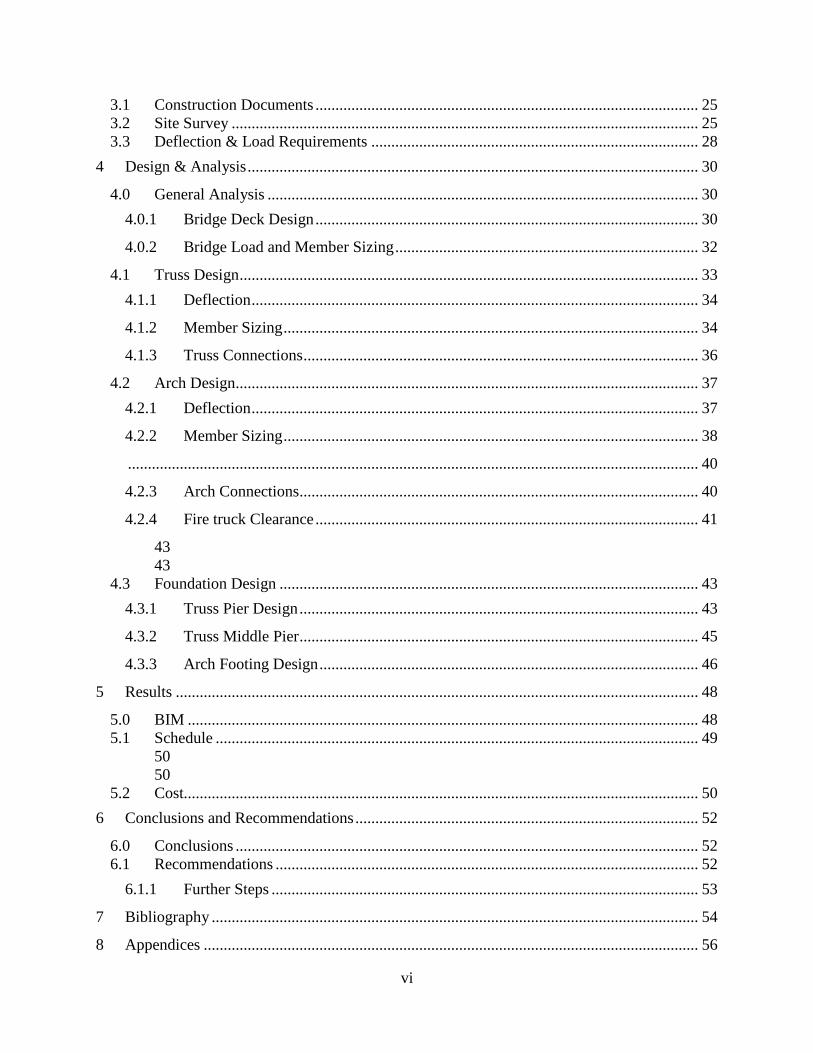