workshop manual alternator EN - Mastervolt generator · PDF filedesign, self-excited ... -...
25
MASTERVOLT Snijdersbergweg 93, 1105 AN Amsterdam Tel +31-20-3422100 Fax +31-20-6971006 www.mastervolt.com V2 Januari 2011 SERVICE MANUAL Mastervolt single phase AC alternators Alternator Manual
Transcript of workshop manual alternator EN - Mastervolt generator · PDF filedesign, self-excited ... -...
MASTERVOLT Snijdersbergweg 93, 1105 AN Amsterdam Tel +31-20-3422100 Fax +31-20-6971006 www.mastervolt.com V2 Januari 2011
SERVICE MANUAL Mastervolt single phase AC
alternators
Alternator Manual
CONTENTS 1. INTRODUCTION 2. LIABILITY 3. SAFETY 4. GENERAL 5. TOOLS 6. BASIC KNOWLEDGE ON GENERATORS
6.1 Frequency 6.2 Voltage and current 6.3 KiloWatts, kilo Volt Amperes 6.4 Power Factor
7. THE THEORY OF CAPACITOR REGULATED ALTERNATORS 8. ADJUSTMENT, FAULT FINDING AND REPAIR
8.1 Adjustment of frequency 8.2 Adjustment of voltage 8.3 Behaviour when overloading. 8.4 Loads and power factor. 8.5 Too high voltage at no load. 8.6 Too low voltage at no load 8.7 The no load voltage being OK and the voltage under load too low. 8.8 No voltage at all. 8.9 Motor starting 8.10 Loads distorting the sine wave. 8.11 Sensitive consumers.
PROCEDURE A: TESTING A CAPACITOR PROCEDURE B: TESTING THE ROTOR DIODE(S) PROCEDURE C: TESTING THE WINDINGS PROCEDURE D: FLASHING THE CAPACITOR APPENDIX 1: BASIC SETTINGS WHISPER GENERATORS APPENDIX 2: TROUBLESHOOTING FLOW CHARTS

1. INTRODUCTION This workshop manual is meant for trained engineers to execute fault finding and repairs on Mastervolt alternators as applied in the generating set models: Whisper 3.5 - 3000/3600 rpm Whisper 6/8/10/11 - 3000/3600 rpm Whisper 6/7/8/9.5/10/11/12/15/16/20 ULTRA - 1500/1800 rpm This manual does not apply to the older models based on Farymann, Lombardini and Westerbeke. There is no detailed information about these models in the manual. However the working of some alternators is the same and the manual could be helpful in solving problems with the folowing generators: Whisper 4000 based on Farymann (out of the program since 1999) Whisper 6000/8000 based on Lombardini (out of the program since 1999) 4.0 BCD and 5.0 BCD Westerbeke alternator. (All other Westerbeke models apply fully different alternators) (Westerbeke generators are out of the program since 2001) This manual does not apply to three phase alternators and does not apply to single phase alternators applied in the Whisper 25 ultra models. 2. LIABILITY The information, instructions, specifications, illustrations and statements contained within this publication are given with our best intentions and are believed to be correct at the time of going to press. Our policy is one of continued development and we reserve the right to amend any technical information without prior notice. Whilst every effort is made to ensure the accuracy of the particulars contained within this publication neither the manufacturer, distributor, or dealer, in any circumstances shall be held liable for any inaccuracy or the consequences thereof. 3. SAFETY
DANGER The voltage generated by AC alternators is dangerous. The danger symbol refers to electrical danger and if instructions and procedures are not strictly observed may result, damage or destruction of equipment or in electrical shock, which will result in severe personal injury or loss of life. Refer to the user manual for more detailed information on safety.
WARNING This danger symbol refers to danger and draws attention to special warnings, instructions or procedures which, if not strictly observed, may result in damage or destruction of equipment, severe personal injury or loss of life. Refer to the user manual for more detailed information on safety.

4. GENERAL The Mastervolt single phase synchronous AC alternator is a brushless, rotating field design, self-excited alternator. Two pole AC alternators are applied to generate 50 Hz at 3000 rpm or 60 Hz at 3600 rpm. Four pole AC alternators work at 1500 or 1800 rpm. 5. TOOLS To do service on Mastervolt alternators the following tools are recommended: - Multimeter A good quality multimeter with a range of 0-1000 VAC, 0-250VDC and capable of reading resistance of less than one Ohm is needed (e.g. Fluke 87). - Frequency meter Frequency can be measured on the AC output with a multimeter. When this function is not available frequency can be measured with another instrument such as a tachometer to measure the engine RPM. - Capacitor tester The capacitor tester should be capable to charge large capacitors. - Diode tester For diode testing a 12VDC, 20-40 Watt light bulb together with a power source, e.g. starter battery is recommended. - Clampmeter A clip on Ammeter to measure AC current with a range of 0-10-50-100-250 Amps is recommended. For some repairs a quite powerful soldering iron is needed. For disassembly standard engineering tools like wrenches, spanners and Allan keys can be used. The use of a torque wrench is needed with engine repairs. Please refer to the engine workshop manual for detailed information. To refit the fittings for the water cooling we advice the use of Loctite 570 or equivalent.
DANGER It is essential that all test instruments be regularly checked for safety and any connection leads, probes or clips checked to ensure that they are suitable for the voltage levels being tested. Never expose “LIVE’ connections unless you have created a safe working area around you. Make sure you have made all other persons in the immediate area fully aware of what you are doing.

6. BASIC KNOWLEDGE ON GENERATORS 6.1 Frequency The Mastervolt generator sets have a diesel combustion engine that is directly coupled in line to an alternator; so the engine and the alternator rotor rotate at the same speed (RPM). The alternator has two or more coils in the rotor that form a magnetic pole pair. Every revolution of the pole pair in the stator windings generates one sine wave of the voltage in the stator windings. The frequency of the AC voltage is standardised at 50 Hz (Europe and many other countries) or 60 Hz (USA and some other countries). The rotating speed of the engine correlates to the frequency of the alternating current. 50 Hz means that the voltage alternates 50 times per seconds. This means that an alternator with one pole pair has to rotate at 3000 rotations per minute to get to 50 Hz (1 x 3000 rpm / 60 s = 50 Hz) and an alternator with two pole pairs has to rotate at 1500 rotations per minute to get to 50 Hz (2x 1500 rpm / 60 s = 50 Hz) The speed of a diesel engine will slow down when the generator is loaded (speed drop). The governor of the engine will give extra throttle to correct this speed drop within manufacturer specifications. The more advanced the design of the governor the more accurate the regulation. Small diesel engines use single speed mechanical governors which give a speed drop from no load to full load of about 5%. More advanced mechanical governors give less speed drop. For example the Whisper 16 ultra has an engine with an all speed mechanical governor that has a speed drop of only 2%. Using an electronic governor the speed drop can be limited to 1 %. This is an option available for most Mastervolt generator sets. 6.2 Voltage and Current An AC generator is designed to produce a voltage suitable for the load to which it is connected. On the Mastervolt single phase generators this voltage level is fixed by the capacitors in the excitation circuit. Because there is no compensation under load, the output voltage will be affected by the generator load. The current drawn from an AC generator is determined by the amount of load connected to it. Current creates a temperature rise in the windings. If the full load current is exceeded on the main stator windings, it will result in overheating of the windings. Similarly, any restriction on the cooling of the generator will result in a rapid increase in the temperature and overheating of the windings.

6.3 Kilowatts (kW), kilo Volt Amperes (kVA) The relation between real power (kW) and apparent power (kVA) is shown in fig. 1
Fig. 1 Relation between real power (kW) and apparent power (kVA) Kilowatts are calculated by the formula: kW = Volts x Amperes x Power Factor 1000 Kilo Volts Amperes are calculated by the formula: kVA = Volts x Amperes 1000 Both equations are multiplied by √3 (1,732) for a 3 phase machine.
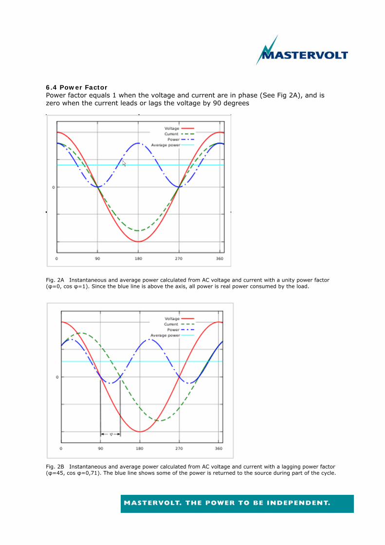
6.4 Power Factor Power factor equals 1 when the voltage and current are in phase (See Fig 2A), and is zero when the current leads or lags the voltage by 90 degrees
Fig. 2A Instantaneous and average power calculated from AC voltage and current with a unity power factor (φ=0, cos φ=1). Since the blue line is above the axis, all power is real power consumed by the load.
Fig. 2B Instantaneous and average power calculated from AC voltage and current with a lagging power factor (φ=45, cos φ=0,71). The blue line shows some of the power is returned to the source during part of the cycle.

Capacitive loads cause reactive power with the current waveform leading the voltage waveform, while inductive loads cause reactive power with the current waveform lagging the voltage waveform (See Fig. 2B). Where the waveforms are sinusoidal, the power factor is the cosine of the phase angle (φ in fig. 2B) between the current and voltage sinusoid waveforms. Equipment data sheets and nameplates often will name the power factor as "cos φ" for this reason.
Cos φ = real power / apparent power
Power factors are usually stated as "leading" or "lagging" to show the sign of the phase angle, where leading indicates a negative sign. A lagging power factor will create a higher apparent power and higher losses for the same amount of real power transfer. The result of this is that with inductive loads there will be a certain amount of reactive power which is not consumed by the load. This will be converted to heat in the generator windings. The Power Factor (pf or cosφ) is a measure of wasted current, which is a product of inductive loads such as motors, transformers(magnetic circuits) and some of lighting. The formula for calculating the Power Factor is: Cos φ = kiloWatts kVA
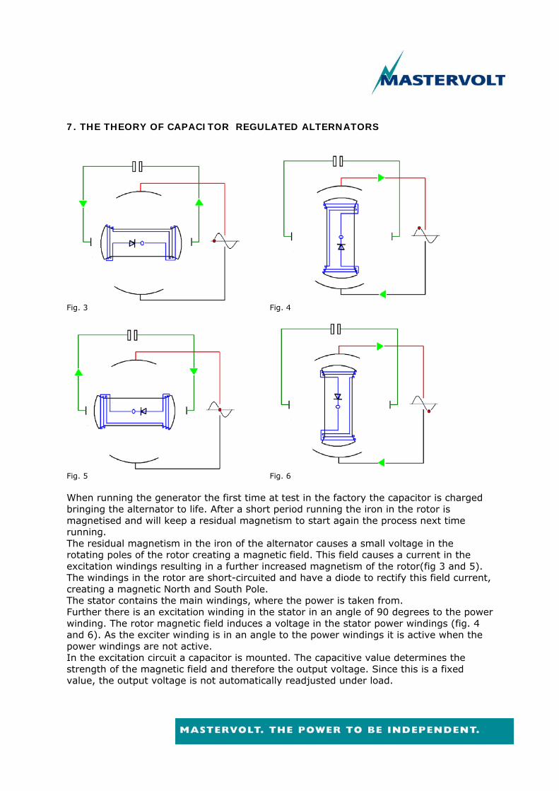
7. THE THEORY OF CAPACITOR REGULATED ALTERNATORS
Fig. 3 Fig. 4
Fig. 5 Fig. 6 When running the generator the first time at test in the factory the capacitor is charged bringing the alternator to life. After a short period running the iron in the rotor is magnetised and will keep a residual magnetism to start again the process next time running. The residual magnetism in the iron of the alternator causes a small voltage in the rotating poles of the rotor creating a magnetic field. This field causes a current in the excitation windings resulting in a further increased magnetism of the rotor(fig 3 and 5). The windings in the rotor are short-circuited and have a diode to rectify this field current, creating a magnetic North and South Pole. The stator contains the main windings, where the power is taken from. Further there is an excitation winding in the stator in an angle of 90 degrees to the power winding. The rotor magnetic field induces a voltage in the stator power windings (fig. 4 and 6). As the exciter winding is in an angle to the power windings it is active when the power windings are not active. In the excitation circuit a capacitor is mounted. The capacitive value determines the strength of the magnetic field and therefore the output voltage. Since this is a fixed value, the output voltage is not automatically readjusted under load.

The main stator windings are positioned in two coils (Fig. 7) that can be put in parallel or in series to generate 115 Volt or 230 Volt. (120Volt or 240Volt for 60 Hz applications)
Fig. 7 So the output voltage depends on the rotor speed, the value of the capacitor, the inductive value of the exciter coil and parameters that are in the construction of the other alternator parts. In the end this means, from the point of view of a service engineer, that there are only two variable parameters that can be controlled. Only when resting for a very long period or in very rare cases after been short circuited the iron could loose its magnetism and should be reactivated by charging the capacitor again. This procedure is called “flashing”. (Refer to procedure D)
8. ADJUSTMENT, FAULT FINDING AND REPAIR Because the output voltage is related to rotor speed and field excitation, it is very important to start with adjusting the frequency (= engine/rotor speed) before adjusting the voltage by increasing/decreasing capacitor value. Please Note: Capacitors will loose capacitive value in time
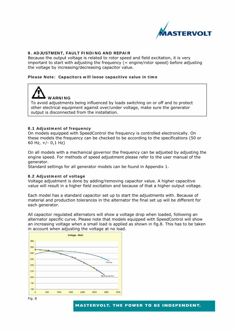
8.1 Adjustment of frequency On models equipped with SpeedControl the frequency is controlled electronically. On these models the frequency can be checked to be according to the specifications (50 or 60 Hz, +/- 0,1 Hz) On all models with a mechanical governor the frequency can be adjusted by adjusting the engine speed. For methods of speed adjustment please refer to the user manual of the generator. Standard settings for all generator models can be found in Appendix 1. 8.2 Adjustment of voltage Voltage adjustment is done by adding/removing capacitor value. A higher capacitive value will result in a higher field excitation and because of that a higher output voltage. Each model has a standard capacitor set up to start the adjustments with. Because of material and production tolerances in the alternator the final set up will be different for each generator. All capacitor regulated alternators will show a voltage drop when loaded, following an alternator specific curve. Please note that models equipped with SpeedControl will show an increasing voltage when a small load is applied as shown in fig.8. This has to be taken in account when adjusting the voltage at no load.
Fig. 8
WARNING To avoid adjustments being influenced by loads switching on or off and to protect other electrical equipment against over/under voltage, make sure the generator output is disconnected from the installation.

8.3 Behaviour when overloading. When overloading the generator the engine speed will drop and the voltage will decrease strongly as a result of the low rotor speed. This will result in an increased current to maintain the same output. (P=UxI) Mastervolt has selected the alternators applied in the generating sets in such a way that the alternator can bring more power than the engine. This prevents the alternator for being damaged by an overload. On generators with a Digital Diesel Control, the DDC will stop the generator on “failure high current”. On all other models the engine rpm will drop because of the overload. 8.4 Loads and Power factor. As the field excitation on capacitor regulated alternators is not regulated but fixed by capacitor value the output voltage will be influenced by inductive or capacitive loads. Purely resistive load, i.e. heating elements, light bulbs, have a power factor of one (pf 1). Welding transformers, motor starting etc. have a lagging power factor, which will bring the output voltage down. Capacitive loads as fluorescent lighting and power factor correction banks produce a leading power factor current and will increase the output voltage. Examples: A. Resistive loads such as light bulbs and heating elements: cos phi = 1 B. Inductive loads:
Electric hand tools cos phi ≈ 0,97
Electric motor (running) cos phi ≈ 0,7 - 0,8
Gas discharge light, welding transformer
cos phi ≈ 0,5
Mastervolt single phase AC generators are specified for pf 1. Since the reading on the DDC is in kVA, the actual load on the generator has to be calculated when a load with a different power factor is applied. kW = kVA x cos φ In normal installations small inductive loads are applied in combination with capacitive loads or are relatively too small to influence the voltage too much. However when applying a strong inductive or capacitive load on a relatively small generator the influence could be too much. Often it will help to compensate an inductive load such as air conditioner motors with a capacitor in parallel. Another solution could be adjusting the no load voltage to compensate for the distorting load but this can give trouble when the load is disconnected.
8.5 Too high voltage at no or low load A too high voltage at no load can have three causes: 1. Rotor speed too high. This can be checked by monitoring the frequency. Adjust engine speed until frequency is within specifications. (see Appendix 1) 2. Capacitor value too high. Replace capacitors for lower value 3. A capacitive load connected to the generator output. This is often seen when a device with power factor correction is connected to the generator output. (e.g. Mass Combi) This can be corrected by replacing capacitors for lower value. On the Whisper 3,5 a small (2 µF) capacitor is placed which can be removed for this purpose. 8.6 Too low voltage at no load. A too low voltage at no load can have the following causes: 1. Rotor speed too low. This can be checked by monitoring the frequency. Adjust the engine speed until frequency is within specifications. (see Appendix 1) 2. Capacitor faulty. Inspect capacitors and connections. 3. Faulty rotor diode. This will be visible by a very low output voltage. (0-60V) 4. Defect in the generator windings. This can be detected by measuring the winding resistance and conductivity to ground. 8.7 No voltage at all. On a new installed alternator or a generator which has not been in operation for a long period, it is possible that the residual magnetism of the rotor is not present. The excitation can be re-activated by flashing the capacitors. (Refer to procedure D) When the generator no output voltage at all, the generator windings could be inspected. The resistance of the windings can be checked without disassembling the alternator. In the terminal box the main and excitation winding can be disconnected (see fig. 7 and Procedure C). The resistance of each winding can be measured and compared with the specifications in fig. 12 or the user manual. Resistance values should be within a tolerance of 10% of the specifications. The electrical insulation of the windings should be checked to earth. Insulation resistance must be over 2 MOhm.
When a high voltage test (Megger test) is performed, the test voltage should not exceed:
Test Voltage = 0.8 (2x rated Voltage + 1000)
WARNING The windings have been high voltage tested during manufacture and further high voltage testing may degrade the insulation with consequent reduction in operating life. Should it be necessary to demonstrate high voltage testing, for customer acceptance, the test must be carried out at reduced voltage level.

8.8 The no load voltage being OK and the voltage under load too low. When the engine speed (frequency) goes down too far when the load is applied, the cause has to be found in an engine problem, most likely in the fuel supply. On models equipped with an electronic governor, the adjustment of the actuator should be checked. When the engine RPM is OK and the frequency does not drop too deep the capacitor could be faulty. (Refer to paragraph 8.6) When the capacitors are OK a winding check has to be done. (Refer to paragraph 8.7). This fault should not be confused with overload or motor starting problems; therefore it is important that the load is well determined and of a resistant character. Be aware that inductive loads will cause the voltage to collapse, as described in paragraph 8.4. 8.9 Motor starting When starting an electric motor and the rotor of the motor is not yet rotating, the current will be very high. This is because there is no inductive resistance yet, the only resistance is the resistance of the windings, which will be very low. As soon as the rotor starts rotating inductive resistance will built up and the current will be reduced to its nominal value. This motor starting current could be 3 up to 7 times nominal value. Many motor manufacturers will specify this as Locked Rotor Amps (LRA). The generator has to bring this current for a very short period. The alternator can be overloaded shortly up to three times its nominal power and the inertia of the flywheel helps the engine to overcome this short overload. However, the voltage will drop dramatically during this period. This can also affect other loads connected to the generators. In some occasions a technical solution can be found in a frequency controller, soft starter or selective transfer switch. Much depends on specific features of the motor. It is important to verify the required start up power with the supplier of the motor. When selecting a generator, it has to be taken into account that motor starting could be required. There are no guaranteed calculations to assure that a specific generator can start a specific motor.

8.10 Loads distorting the sine wave. Some loads distort the sine wave of the alternator. This can cause other equipment or the distorting device itself to malfunction. Some earlier generations of (thyristor based) battery chargers regulate the charging voltage by “cutting segments out of the sinus” to reduce the voltage. The same effect can be caused by (thyristor based) motor controllers used in some washing machines. Some microwave ovens and induction hobs switch on and off constantly with distorting effects on the sinus as well. This could cause the sine wave of the alternator to be distorted in such a way that other devices will be deregulated. For example, a dip in the sine wave caused by a fast switching load could be interpreted by some devices as a higher frequency and this device will be switched off by an over-frequency protection. Sometimes putting a resistive load in parallel can be a solution. Another method to solve the problem is to power the device which causes the problem with an inverter and use the generator to charge the batteries with a battery charger to power the inverter. However the best way is to avoid these problems by being critical in purchasing devices like: battery chargers, washing machines and micro waves. 8.11 Sensitive loads. Some devices are very sensitive to the voltage or the frequency offered by the generator. Because standards for voltage variations on the public net are relatively large, problems with voltage deviations are not very common. Most problems are therefore frequency related. When a load is switched on a generator, this will be visible on the generator output frequency. The frequency will be more affected when the ratio between load and generator will be smaller. (A 2kW load will give more frequency distortion on a 6kW generator than on a 25kW generator) All devices that have timers and clocks which are essential to control the functioning of the device will be influenced by a fluctuation in the frequency. Some electronic motor controllers accept a frequency “window” that is very narrow. In some cases this is practically zero. (e.g. washing machines with advanced “eco” controllers for the motor drive.) Sometimes a small frequency adjustment can help to overcome the problem but better is to avoid the use of sensitive consumers on a small generator. Another way to solve the problem is to power the device with an inverter and charge the battery with a separate battery charger from the generator. Mastervolt has an electronic governor on most models to bring the frequency variation within 1 %. However, an overload for instance caused by motor starting, can still cause a frequency dip. Since mounting an electronic governor afterwards is quite expensive the problem can better be solved by selecting less critical consumers or a bigger generator.

PROCEDURE A: TESTING A CAPACITOR
Over the exciter winding are one or more capacitors (in parallel). When the voltage is too low this could be caused by a faulty capacitor. First the capacitor should be inspected visually for any deformation, swelling, decolourisation, burning spots etc. When the capacitor looks OK it can be field tested in the following way: Disconnect the wires and connect a multimeter (highest Ohm scale) to the capacitor terminals. The meter should go to zero Ohms and slowly return to high. Discharge the capacitor again and reverse the multimeter leads. The same result should be obtained. If the meter goes down and stays at zero Ohms, the capacitor is faulty (shorted). Infinite resistance or no rise in resistance indicates a shorted capacitor. If the meter fails to go down to zero, the capacitor is faulty. (open circuit) A special capacitor tester can be used for checking the capacitor microFarad (uF) value. Because the output voltage of most multimeters is not sufficient, a multimeter set to capacitor test mode cannot be used for this purpose. When any doubts change the capacitor. When ordering new capacitors always refer to the value as different values could be used in the same generator model. More capacitors can be put in parallel to get to the correct value. To get the maximum lifetime of the capacitors, it is recommended to use more capacitors with a low value to divide the current instead of using one capacitor with a high value. (e.g. 3x 30uF instead of 2x 45uF).
DANGER Capacitors must be discharged before handling as they store electricity and can contain a potentially lethal charge even when disconnected from their power source. Discharge the capacitor by bridging the terminals.

PROCEDURE B: TESTING THE ROTOR DIODE(S) In the rotor of the alternator are one or two diodes that rectify the field current. Two diodes are only used in the earlier Lombardini based Whisper 6000 an 8000, the Farymann based Whisper 4000 and some earlier series of the Whisper 3500. All other models has only one diode. As it is often very difficult to get access to the diode one should not too early decide to disassemble the alternator to inspect the diode, but exclude all other possibilities first. In most cases a diode failure is a result from a voltage peak or load surge. This can be caused by e.g. an overspeed or stopping the generator without disconnecting the load. Checking the diode When only one diode is applied and it fails the output voltage will be very low. (0-40 V) For testing or replacing the diode the alternator has to be disassembled to get access to the rotor (See fig. 9).
Fig. 9 Rotor diode When there is suspicion about a faulty diode, the following test can be done: Unsolder the connection to the diode and to take out of the diode. Use an appropriate soldering iron to shorten the soldering time. Excessive heat will damage the diode. Take care that no soldering splashes on to the windings, as it will damage the insulation. Connect one end of the diode to the plus of a 12V battery and measure between the other end and battery minus. The voltmeter should read battery voltage or 0. Swap the diode connections and perform the same measurement. If the result is the same as previous measurement, the diode is broken. If the result is the opposite of previous measurement, the diode is still OK. When the alternator is taken apart for fault finding, we recommend to replace the diode, because of the amount of work involved in disassembling the alternator is high in relation to the low costs of the diode. Test to check if the diode is faulty when there are two diodes in the rotor. When the voltage is much too low (between 60V and 190 Volt for 50 Hz models) it could be that one of the diodes is faulty. After checking and replacing the capacitor the following test can be done: First check all other probable causes and check the frequency. Run the generator at no load and measure the voltage and keep an eye on the reading, load the alternator with a small resistant load of about 200 Watt. When the voltage slightly increases this indicates the diodes to be OK. When the voltage drops further this indicates one of the diodes to be faulty.
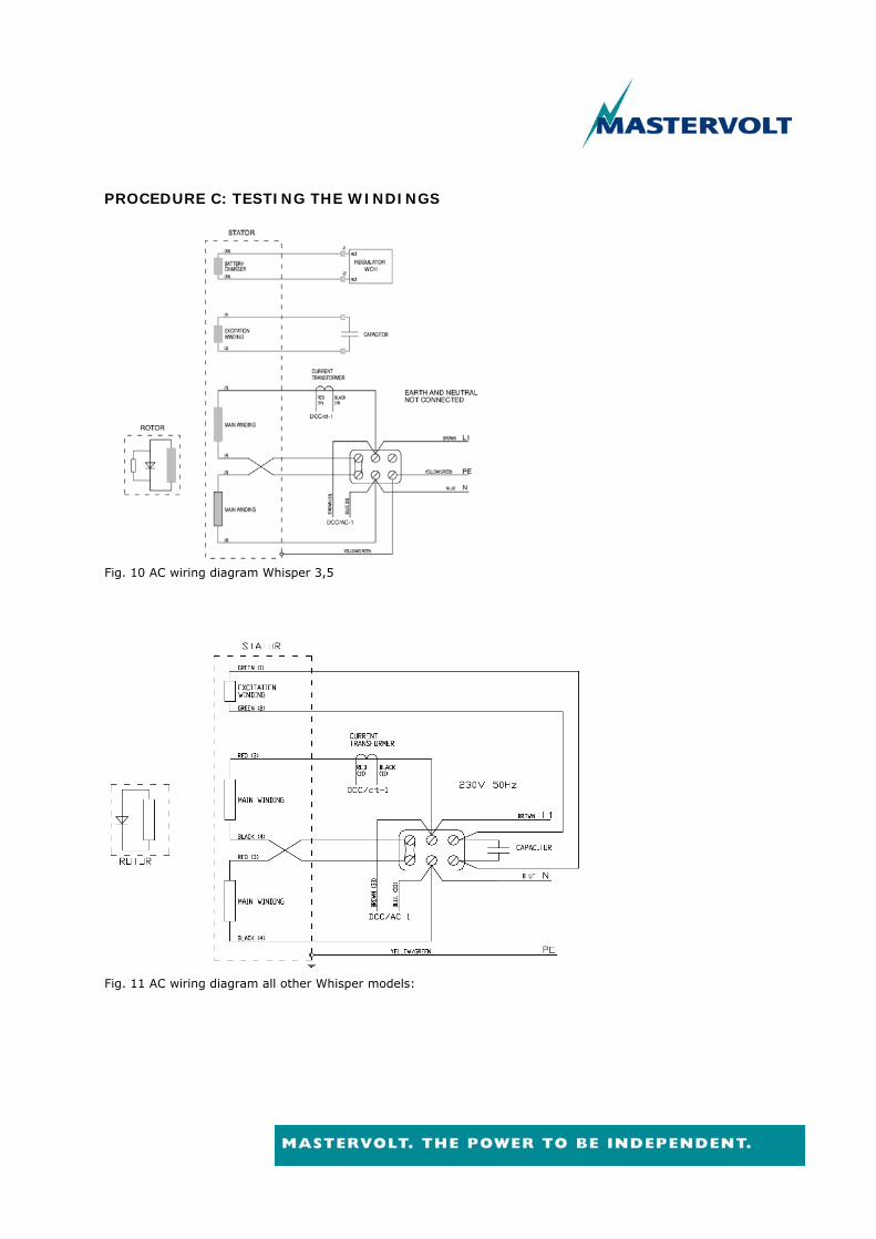
PROCEDURE C: TESTING THE WINDINGS
Fig. 10 AC wiring diagram Whisper 3,5
Fig. 11 AC wiring diagram all other Whisper models:

Checking Continuity to the ground and between the windings All windings should be checked for continuity to ground/alternator housing and also check that no continuity exists between the different windings. Insulation resistance must be over 2 MOhm. Testing the exciter windings Before measuring the resistance of the exciter windings the AC value over the capacitor while the generator is in operation can be measured. This should be 350 up to 450 Volt. Measuring the windings with an Ohm meter
Before measuring the excitation winding the capacitor should be disconnected. When measuring the other windings, these should be isolated to get a correct measurement. Remove the output leads, the ground connection and the brass interconnects. The coils can be identified by the numbered wires. Refer to the diagrams in fig. 10 and 11. As these resistance values are very low a good quality measuring instruments has to be used. The measuring results have to be used as an indication. Of course a fully open circuit (infinite measurement) or a 100% short circuit (zero Ohm) are easy recognisable. Slightly different measuring values can be caused by a higher or lower humidity in the windings. Refer to fig. 12 for the correct values. A tolerance of 10% from these values is acceptable. The windings should be absolutely free from ground and from the other windings.
DANGER Discharge the capacitor before handling or performing any measurements. Capacitors can store a potentially lethal charge even when disconnected from their power source. Discharge the capacitor by bridging the terminals.

BATTERY
CHARGING WINDING
STATOR (both windings
in series)
ROTOR EXCITATION
Whisper 3,5 50Hz 0.15 1.2 2.1 2.4 Whisper 3,5 60Hz 0.13 0.71 2.1 2.0 Whisper 6 50Hz n.a. 0.54 0.93 1.4 Whisper 6 60Hz n.a. 0.34 0.93 0.82 Whisper 8 50Hz n.a. 0.54 0.93 1.4 Whisper 8 60Hz n.a. 0.34 0.93 0.82 Whisper 10 n.a. 0.36 1.05 0.85 Whisper 11 n.a. 0.26 1.05 0.72 Whisper 6 Ultra n.a. 0.77 2.0 1.91 Whisper 7 Ultra n.a. 0.46 2.0 1.42 Whisper 8 Ultra n.a. 0.32 2.6 0.75 Whisper 9,5 Ultra n.a. 0.29 2.6 0.75 Whisper 10 Ultra n.a. 0.32 2.6 0.75 Whisper 11 Ultra n.a. 0.29 2.6 0.75 Whisper 12 Ultra n.a. 0.22 3.4 0.64 Whisper 15 Ultra n.a. 0.19 3.4 0.43 Whisper 16 Ultra n.a. 0.18 3.9 0.42 Whisper 20 Ultra n.a. 0.15 3.9 0.36 Fig. 12 Winding resistance in Ohm Testing the battery charging circuit (Whisper 3,5 / 3500) The battery charging winding is fully separate from the AC winding. When the AC windings are faulty this will affect the performance of the battery winding, but not reverse. The winding will measure about 16 up to 17 Volt AC when the generator is in operation. Megger testing
When a high voltage test (Megger test) is performed, the test voltage should not exceed:
Test Voltage = 0.8 (2x rated Voltage + 1000)
The generator must not be run if the minimum insulation value of 1,0 Megohm is not obtained.
WARNING The windings have been high voltage tested during manufacture and further high voltage testing may degrade the insulation with consequent reduction in operating life. Should it be necessary to demonstrate high voltage testing, for customer acceptance, the test must be carried out at reduced voltage level.

PROCEDURE D: FLASHING THE CAPACITOR Residual magnetism can disappear after the generating set being out of service for a long period or after disassembly of the alternator. When the residual magnetism has disappeared it can be brought back by charging (flashing) the capacitor. This can be during the starting of the generator. The only safe way to go is to charge the capacitor with the help of a 9 volt pocket battery while the generator is starting. (see fig. 13) Make sure the battery is removed when the generator has an output. A small spark can occur during flashing.
Fig. 13 Flashing of the capacitor Charging a capacitor with the help of the 12 V starter battery is not recommended.
DANGER When the generator set start battery is used for flashing, this can cause heavy sparking, fire and injuries.
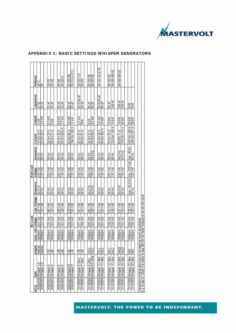
APPENDIX 1: BASIC SETTINGS WHISPER GENERATORS
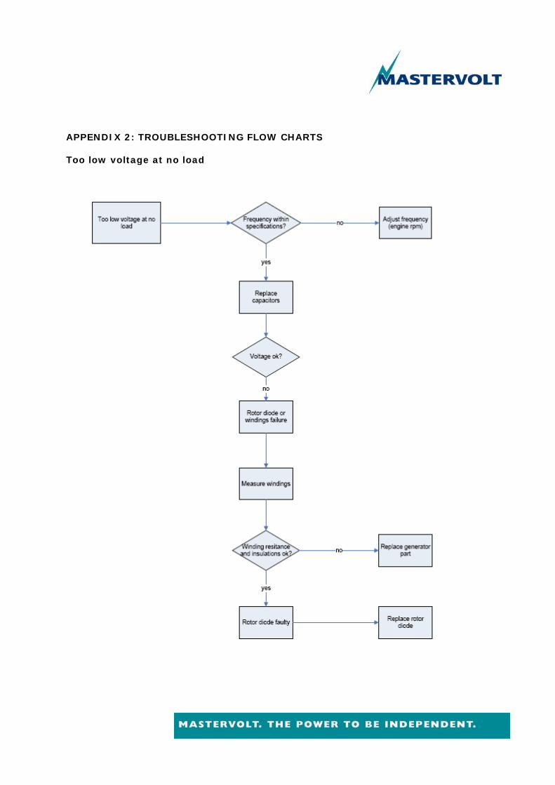
APPENDIX 2: TROUBLESHOOTING FLOW CHARTS Too low voltage at no load

Too high voltage at no load
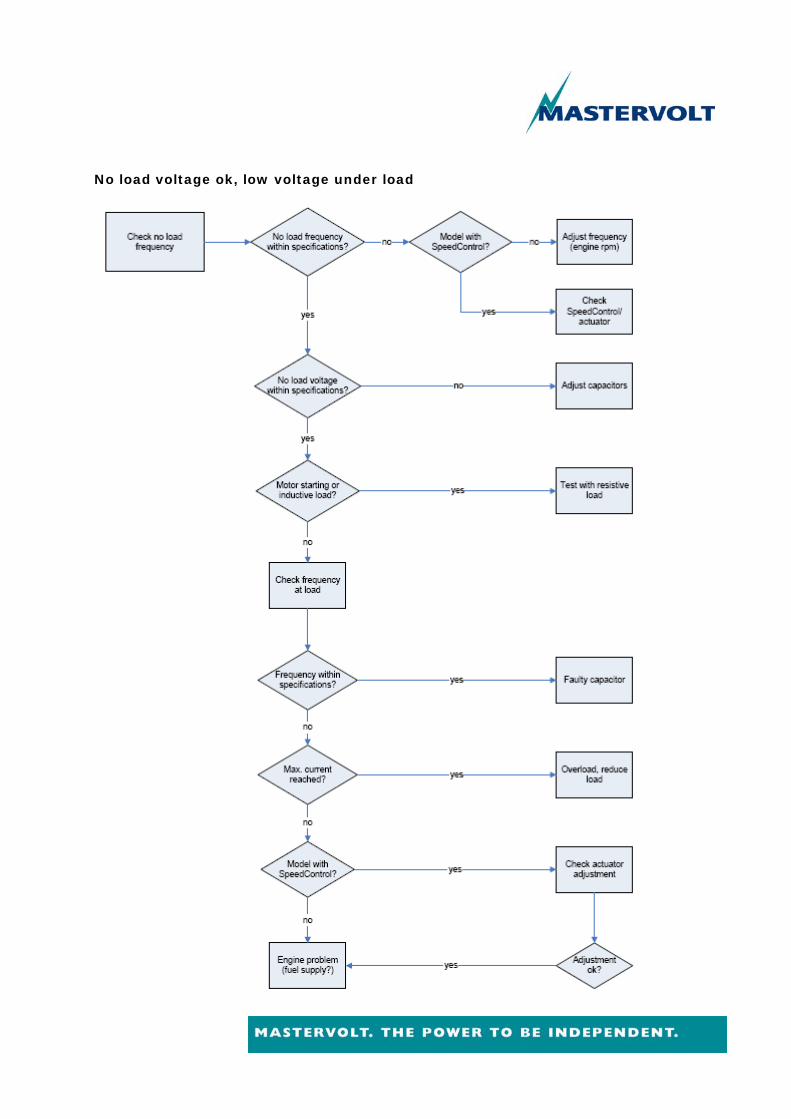
No load voltage ok, low voltage under load