
Ereditarietà multipla C++ method vs Twin-Objects Daniela Briola Orlin Velinov.

Working with objectsThe OOram Software Engineering Method
Trygve Reenskaugwith P. Wold and O.A. Lehne
Document date: 29 March 1995Last update on: 29 March 1995 at: 23:05
Printed on: 29 March 1995 at: 23:06
We dedicate this book to Douglas Engelbart because he made us understand that computers should be used to augment the human intellect
rather than to replace it, and because his deep understanding of the symbiosis between humans and information is still far ahead of the rest of
us.
This is a preprint. Do not copy. All rights reserved.
TASKONWork Environments
Taskon, Gaustadalléen 21, N-0371 Oslo 3 Norway. Tel. + (47) 22 95 86 31 Telefax: + (47) 22 60 44 27

There are two ways of constructing a software design:
- One way is to make it so simple that there are obviously no deficiencies
- and the other way is to make it so complicated that there are no obvious deficiencies.
-- C. A. R. Hoare
29 March 1995 23:05
©Taskon 1992. Page 0

Chapter 0Preface
Goals
Real software for real users
The main theme of this book is to describe complex phenomena as structures of interacting objects. Object technology is applicable to a wide range of phenomena on many different levels. Examples are work procedures on the enterprise level; large-scale applications on the systems level; and small, technical details on the program design level.
The goals of the book are
1. To provide a comprehensive description of the object paradigm and its applications
2. To show how it supports a number of different views on the samemodel; permitting the analyst to work with a data-centered approach, a process-centered approach, or a combination of the two.
3. To show how very large and complex systems can be described by a number of distinct models.
To show how composite models can be derived from simpler basemodels.
4.
To describe a number of powerful reuse techniques.5.
6. To describe how a systematic policy of reuse impacts work processes and organization.
To show how very large systems can be described and managed in a decentralized manner without central control.
7.
Motivation
A number of important books on object-oriented analysis and design have been published in recent years. The most influential are probably[Cox 87], [Wirfs-Brock 90], [Booch 94], [Rumbaugh 91], and
Motivation29 March 1995 23:05
Preface ©Taskon 1992. Page 1

[Jacobson 92]. All these methodologies are based on the object as the common building block and on the class as a common abstraction on the objects.
There is a widespread feeling that the methodologies could profitably be merged into a single one, and that the concepts and notation of the composite methodology could be standardized. We feel that such standardization will be premature. Objects and classes represent two different levels of abstraction; each is suited to the expression of certain properties. Static properties and relations are best expressed in terms of classes. Examples are attributes and relations; most notably for expressing the inheritance relation. Dynamic properties are best expressed in terms of objects. Examples are message interactions (scenarios), use cases, and data flows.
The class/object duality is as essential to object oriented programmingas it is disruptive to object oriented modeling. A future modeling standard should be built on a unified conceptual framework with sufficient expressive power to describe all interesting aspects of an object system within a single, integrated model.
One candidate is the OOram role model. This conceptual framework combines the expressiveness of the object and the class. All information that can be expressed in a class-based model can be expressed in a role model. All information that can be expressed in an object-based model can be be expressed in the same role model. Furthermore, there is a synergy effect from merging the class and object properties into one and the same model. The result is increased leverage for the decomposition of large systems and for the systematicreuse of proven components.
The essence of the object-oriented paradigm is the modeling of interesting phenomena as a structure of interacting objects. The architecture of a home can be represented as a structure of room objects interconnected with doors and hallways. A model which says that a room may be adjacent to another room is insufficient. We need to be able to say that the dining room shall be adjacent to the kitchen; and that the childrens' playroom shall be far away from the master bedroom.
In an OOram role model, patterns of interacting objects are abstractedinto a corresponding pattern of interacting roles. In our simple example, one object will play the role of dining room, another the roleof kitchen, etc. The roles are interconnected to represent the layout of
Motivation 29 March 1995 23:05
©Taskon 1992. Page 2 Preface

the home. The corresponding objects will belong to the same class if they have the same properties; they will belong to different classes if they have different properties. The role model abstraction belongs to the realm of modeling. The class abstraction belongs to the realm of implementation.
An object can play several roles. This permits a systematic separationof concern by describing different phenomena in different role models. And conversely, it permits the synthesis of a derived model by letting its objects play several roles from different role models.
This book is about the added leverage provided by role modeling as opposed to the conventional class modeling. The nature of this leverage is listed under the heading of Goals above. The added leverage motivates our introduction of a new and precisely defined setof concepts and a new notation -- it motivates this book.
Audience
Familiarity with computers assumed
We assume that you are familiar with how computers and computer programming influence modern information processing, but do not assume familiarity with a particular programming language or operating system. Most of the book is written for the manager and person of business who is searching for new and better ways to produce software, for the consultant who wants to use objects to design new business organizations, and for the system creator who wants to understand how to exploit the full power of object orientation. A few chapters are clearly marked as being directed to theexpert computer programmer.
The structure of this book
This book is written to be read in sequence, but we suggest you skip chapters which look uninteresting on your first reading. It is organizedin twelve chapters as follows:
A reader's guide to this book
29 March 1995 23:05 The structure of this book
©Taskon 1992. Page 3Preface

1. The main ideas. An introduction to industrial software production, object orientation and the OOram method providing an intuitive understanding of the main ideas. We recommend that you study this chapter before embarking on the more detailed expositions in the remainder of the book. It should help you to recognize what objects can do for you and help you to set your goals.
Role Modeling. How to create object-oriented models of interesting phenomena. This chapter should help you create your first models and establish your work processes for analysis and design.
2.
Role model synthesis. How to create derived models from simpler ones. Read this chapter to understand how you can divide your problem space and still conquer the whole. If your systems are on a large scale, this chapter should help you tackle them. But be warned; you will need to collect a solid body of experience beforeyou can reasonably expect to establish a successful reuse operation.
3.
Bridge to implementation. How to specify objects for implementation in different languages, how to implement the specifications, how to check the implementation against the specification, and how to analyze an existing implementation to create one or more role models describing it. This chapter ties the concepts of the OOram technology to the concepts of two popularprogramming languages, Smalltalk and C++. This may be the chapter which makes the OOram technology real to you if you area programmer. If you are not, you may safely ignore the whole chapter.
4.
5. Creating reusable components. How to create reusable components by exploiting the object inheritance properties. You cannot reuse something before you have used it. There is no snakeoil that will magically give you the benefits of reuse; but we present guidelines that will help the serious practitioner gradually build a library of reusable components. Once you master the technology of synthesis, you search for reusable components which transform your large and complex projects into small and manageable ones.
Additional role modeling concepts and notation. Presents additional role model views that have proven to be useful in certain circumstances.
6.
The structure of this book 29 March 1995 23:05
©Taskon 1992. Page 4 Preface

7. Case study: Development of a business information system. Stresses the work processes and the relationships between three important models: a model of the system environment, an information model, and a task/tool/service model.
Case study: The analysis and design of a real time system. The case stresses embedded systems with their behavioral aspects described with Finite State Machines. It also exemplifies a number of different approaches to the implementation.
8.
Case study: The creation of a framework. Describes the creation of a fairly large framework supporting reuse. The study describes all stages in the creation of the framework, including reverse engineering of existing systems and forward engineering of the new framework.
9.
Organizing for software productivity. Describes how to design a work organization in the form of a value chain; and how to select appropriate technology for the different layers. This chapter indicates the structure of a future software industry, and is writtenfor readers who are serious about the large-scale provision of customized software. It offers the greatest challenges and promises the biggest rewards. It advises you to reconsider your whole software business, to look for repeating questions which can exploit reusable answers, and to move from a job shop organization to an industrial one.
10.
11. Advanced reuse based on object instances. This chapter is writtenfor the specially interested reader. We describe how you can compose a system from a pool of predefined objects. This technology is an extension of the OOram role modeling technology that is the technology basis of the first part of the book. It is not as mature, but it can become an important supplement to the OOram role modeling technologies.
12. Case study: Intelligent Network Services Organized in a Value Chain. Exemplifies a complete software industry. Specifies a complete value chain with the actors and appropriate technology for each layer. The study shows how all the different reuse technologies have a place in a complete value chain.
The structure of this book29 March 1995 23:05
©Taskon 1992. Page 5Preface

Using this book
This book helps you get started on
industrializing your software production.
The book describes the principles behind an industrial approach to software production. We claim that the technological basis of industrial software production should be object orientation. A large part of the book is devoted to explaining all the different things you can do with objects; we will also match the different operations on objects to the needs of typical value chains for software production.
No viable industry was ever established on an ad hoc basis. Object orientation and industrial production of software are not some kind of magic that will produce immediate results in your next software project. You must identify your potential customers and fully understand their current and future needs. You must identify the complete value chain, and carefully consider your place in that chain. You must devise optimal technologies and production facilities for every step in the chain. You must establish the required infrastructure for supporting the process, and staff the production facilities with people trained for their tasks. This book can help you getting started, but it is only your own long term dedication and investment in time and resources that can lead you to the goal.
The software industry is still in its infancy, and it will take many yearsto establish an effective industrial infrastructure. We therefore recommend a gradual transition from the miserable present to the glorious future. The winners will be the companies with a clear vision,an effective strategy, and the stamina needed to transform their operations from the general job shop to the industrial enterprise.
Gradual transition tofull industrialization
required
Figure 0.1 illustrates our recommended progression through objects and the OOram method. We have indicated that the first step should be to implement systems with objects. If you are a programmer, this means that you should start by writing small, object-oriented programs. If you are a developer of enterprise processes, you should create some simple processes in object-oriented terms. This first step is shown dashed, because object-oriented programming is not the focus of this book. The remaining steps indicate our recommended progression into the rich world of objects.
29 March 1995 23:05 Using this book
Preface©Taskon 1992. Page 6

Creating reusable components(Chapter 5)
Role model analysis and design(Chapter 2)
Combining role models through synthesis(Chapter 3)
Organizing for software productivity(Chapter 10)
Object-oriented implementation
Establishing a software factory(Chapters 10, 11, and 12)
Figure 0.1 Stages in the application of the
OOram method
Taskon invites cooperation
It is our hope that this book will cause the wide spread adoption of theOOram method. Taskon markets OOram processes, tools and consultancy services for a number of application areas. We invite consultants to build special methodologies based on our products; we invite other vendors to create competing products; we invite potential competitors to cooperate with us to ensure interoperability between the products to the benefit of all.
Background
The book is based on continuous experience with objects since 1975 and practical experience in the borderland between software engineering research and the production of software for computer aided design, production control, management information systems, and telecommunications since 1960. In all our work, the goal has beento create industrial strength software for real users. The software engineering methodologies and tools have been created in response toour own needs and to the needs of our partners, and the success criterion has been that they enabled us to support our clients more effectively.
Our experience has clearly shown that object orientation is a powerfulparadigm which is applicable to a wide range of problem areas. We have used it to design improved organizations in oil companies; to describe basic, reusable services in a distributed environment; to design client-server systems; and to specify and implement business information systems.
Object orientation is a powerful paradigm
29 March 1995 23:05 Background
Preface ©Taskon 1992. Page 7

Our most exciting experiences are with systematic reuse and an industrial approach to software production. This enables us to producelarge systems in small projects, which we believe is the key to the effective production of quality software.
Large systems, small projects
Different methodologies for different problems
Our accumulated experience also leads to a negative conclusion: There is no silver bullet that will miraculously solve all problems. Thework process, the organization and the technology has to be adapted to the problem at hand and the people who are to solve it. We do therefore not have the audacity to present a complete methodology which will solve all problems. We rather present a foundation which can support many different methodologies for different purposes, we call it the OOram method.
Acknowledgments
The senior author has written most of the words you find in this book, and when the pronoun "I" is used, it refers to the senior author. Per Wold has been an essential partner, posing important questions and bysuggesting appropriate answers throughout the creation process. Odd Arild Lehne has brought his extensive teaching and consulting experience to bear on the book's structure, examples, and case studies.
Jørn Andersen, Lasse Bjerde, Jon Ola Hove, Eirik Næss-Ulset, and Carl Petter Swensson have been members of the Taskon book committee. The patience and perseverance they have shown by reading and rereading a steady stream of drafts and their help in shaping the form and contents of the various chapters of the book cannot be overestimated.
The development of the OOram method has taken place at the Center for industrial research (SI) in Oslo, at Taskon AS and at the University of Oslo. We regard a good development team as a team where ideas and results flow freely, and where the success of the whole team is the only measure of the success of the individual team member. We have always had a very good team, and the results presented in this book have been contributed by a great number of dedicated people over the past 20 years. It is impossible, in retrospect,to identify the individual contributions or even contributors, and we thank them all.
29 March 1995 23:05 Acknowledgments
Preface©Taskon 1992. Page 8
Our research in the field of applied object-orientation would have died at certain critical times in the late seventies without the wholehearted support by Bjørn Ørjansen, then director of research at SI. Important work on an object-oriented planning and control system was supported by the Aker Group in the early seventies as part of our long cooperation about the Autokon system for the computer-aided design of ships.
The Royal Norwegian Council for Industrial and Scientific Research has given support through several grants: Grants for the porting of Smalltalk-78 to local equipment and for creating the first Norwegian Ethernet in 1980; for the research that lead to first prototypes of our present range of products in the research and development program Efficiency and Quality in Engineering; and for our work with an object-oriented architecture for very large, heterogeneous systems in the Eureka Software Factory Project.
I had the good fortune to spend a year as visiting scientist with Alan Kay, Adele Goldberg and the Smalltalk group at the Xerox Palo Alto Research Center (PARC) in 1978/79. This was a wonderful experience which completely changed my life, and it is impossible to fully express my gratitude for the help and inspiration I received. I particularly want to thank Adele for the support and interesting discussions that lead to the creation of the first version of the Model-View-Controller; this was probably the world's first reusable, object-oriented framework. After this visit, we got a license to port Smalltalk-78 to local equipment in Norway. This port was excellently performed by Bruce Horn, who was then a student at PARC. My colleagues and I are eternally grateful to Bruce and Xerox for giving us early experience with the world's most exciting programming environment. We are also very grateful to Bruce for permitting us to publish his work on user interface design which you will find in chapter 7.3.2.
We are strong believers in the axiom that programmers should take their own medicine. The authors and all members of Taskon team are heavy users of our methodologies and tools, and this book is written with our OOram documentation tools. Our own use supplies a steady stream of ideas for improvements, but feedback from other users is also crucial: They solve different problems and have different ideas about what the methodologies should do for them. We therefore thankour customers and other users of the OOram method for constructive criticisms and ideas for improvements.
Acknowledgments29 March 1995 23:05
©Taskon 1992. Page 9Preface

Our application of the OOram method to the field of telecommunications would have been impossible without the initiative of Raymond Nilsen of Norwegian Telecom Research. We thank him, Tom Handegård, Klaus Gaarder, Bengt Jensen and their colleagues for having taught us what we know about telecommunications and for a number of stimulating discussions in a creative atmosphere. We also thank Dag Brenna and Martha Haraldsen of Garex A/S, who have given valuable feedback on the application of the OOram technology to the large-scale production of customized communication systems.
We express our sincere thanks to Arne-Jørgen Berre for comparing the OOram method to the currently popular methodologies for object-oriented analysis and design, and for providing important insights intothe world of distributed computing. We are also grateful to Espen Frimann Koren, Magnus Rygh, and John Lakos for their preparation and discussion of the programming examples in C++. Stein Krogdahl has helped create the the OOram language presented in Appendix A, but does not want to be responsible for this first version of the language.
A number of people have contributed their time and expertise to reviewing parts or all of this book. We would like to express our sincere thanks to Ralph Johnson, Doug Berrett, Mats Gustafsson, GeirHøydalsvik, Else Nordhagen, Witold Sitek, Anne-Lise Skaar, GerhardSkagestein, Pål Stenslet, Michael Thurell, and the anonymous reviewers who have all contributed valuable and insightful comments.
Finally, I would like to express my sincere thanks to a programmer and systems analyst who has been providing inspiration, unfaltering support and valuable advice all through the past 40 years: my wife Oddbjørg Råd Reenskaug.
OOram is a registered trade mark of Taskon A/S. ObjectsWorks\Smalltalk is a registered trademark of ParcPlace Systems, Inc. LEGO is a registered trademark of the LEGO Group. DecWindows is a registered trademark of Digital Equipment Corporation. Ole is a registered trademark of Microsoft Inc.
Acknowledgments 29 March 1995 23:05
Preface©Taskon 1992. Page 10

Chapter 1The main ideas
This chapter gives an overview of object orientation as it is exploited by the OOrammethod and of our general ideas about organizing software production in value chains.
We recommend that you read this chapter before embarking on the details in the remainder of the book.
The OOram method (p. 12??)The problem and the three dimensions of the OOram solution
The Technology Dimension (p. 17??)Representing the real world as objectsThe powerful role model abstractionSeparation of concern and Role model SynthesisOOram implementation links role models to computer programsOOram reuse technologyComparison with other methods
Process and deliverables (p.41??)Introduction to the model-building processesIntroduction to the system development processesIntroduction to the reusable assets building processes
Organization (p. 48??)Industrial software productionThe value chainThe OOram fountain modelThe urgent need for effective metrics
29 March 1995 23:05
©Taskon 1992. Page 11The main ideas

The OOram method1.1
In a nutshellIn the software engineering community, a methodology usually denotes an approachto accomplish a task. We find it convenient to study methodologies in three dimensions: a technology dimension describing the concepts, notation, and tools; a process dimension describing the steps to be performed (mainly in parallel) together with the deliverables from each step; and an organization dimension describing the organization for effective software development.
The OOram idea is that there is no single, ideal methodology. We need different methodologies for different purposes; each tailored to a specific combination of product, people, and information environment.
The OOram method is generic: it forms a framework for creating a variety of methodologies. They will all build on selected parts of the OOram technology; and will have their own, unique processes and organization. We stress the common technology in this book, but we will also discuss aspects of the other two dimensions in order to help you create your own methodology that is optimized for your requirements.
The "software crisis" was first officially recognized at the NATO Conference on Software Engineering in Garmisch, Germany in 1968. The conference identified the problem and started a discussion about its solution. Much has been achieved in the intervening period, but requirements have grown at least as fast as our ability to satisfy them. Today, more than twenty-five years and many "solutions" after the Garmisch conference, we still have a software crisis and we are still searching for better solutions.
The software crisis
The latest solution to catch the fancy of system developers is the technology based on the object paradigm. The first object-oriented programming language, Simula, was developed in Norway in the sixities. The field got a tremendous boost when the Smalltalk language and development system became available in the early eighties. The introduction of the C++ programming language made object orientation generally acceptable to the systems programming community. (FOOTNOTE: See [Birth 73], [Gold 83]), and [Strou 86])
Object-oriented methods are the latest "solution"
Books on methodologies for object-oriented analysis and design appeared in the late eighties. The different authors started out with different approaches to the common theme of describing interesting things with objects. Cox, Booch, and Wirfs-Brock based their work onthe concepts of object-oriented programming languages. Rumbaugh
1.1 The OOram method 29 March 1995 23:05
The main ideas©Taskon 1992. Page 12

and Jacobson started from earlier modeling paradigms; Rumbaugh from a data-centered approach and Jacobson from a function-centered approach.(FOOTNOTE: See [Cox 87], [Booch 91], [Wirfs-Brock 90], [Rumbaugh 91], and [Jacobson 92].)
Object technology has moved from the exotic to the feasible. It is nowrapidly moving from the feasible into the mainstream of systems development.
The reason for the popularity of objects is easy to see. We have earlierbeen using a number of different modeling paradigms to describe different aspects of our systems. The data-centered approaches, e.g., Entity-Relation modeling, were excellent for modeling the static properties of information; but they were weak for modeling functionality. The behavior-centered approaches, e.g., functional decomposition or finite state machines, were great for modeling the dynamics of the system; but they were weak on the modeling of data.
A powerful paradigmmerging many
earlier concepts
The advantage of the object-oriented paradigm is that it neatly combines the strengths of the data-centered and the behavior-centeredapproaches. It is great for modeling information and it is great for modeling behavior.
Like all previous solutions, object orientation is no panacea. It is still easy to create lousy systems and hard to create good ones. Objects offer no more and no less than an opportunity for mastering even harder problems than we have been able to master in the past.
BOX: Methodology and method.In normal usage, a method is an approach to accomplishing a task, and a methodology is the study of a family of methods. Within the software community, the term methodology usually denotes an approach to accomplishing a task. We have therefore taken the liberty to let the OOram method denote our strategy and technology for the creation of a family of methodologies for different purposes.
Within the software community, a methodology is taken to mean an approach to accomplishing a task. (See box.) We do not believe that we will ever find an ideal methodology that will serve all purposes equally well. On the contrary, we believe that a methodology not onlyhas to be optimized for its goals; it should also be tailored to suit the culture, competence and preferences of its people. It is therefore not possible to create an overall methodology which covers all needs. Butwe do give guidelines, examples, and case studies that may be helpfulwhen you create your own solutions to your problems in software creation; in model and software reuse; or in setting up an organizationfor the large-scale provision of customized software.
The OOram method is a frame of
reference
1.1 The OOram method29 March 1995 23:05
The main ideas ©Taskon 1992. Page 13

The OOram method is a frame of reference for a family of object-oriented methodologies. It captures the essence of object orientation, which is to model interesting phenomena as a structure of interacting objects. It offers the role model as a powerful abstraction that supports a very general separation of concern. The notion of role model synthesis supports the construction of complex models from simpler ones in a safe and controlled manner, and offers many opportunities for the systematic application of reusable components.
Processwith Deliverables
Technology(Concepts-Notation-Tools)
Organization(Value Chain)
Impl.
Des.
Req.
User
Real World
Reuse Technology
Objects Roles Implement-ation
Figure 1.1 Three dimensions of system
development methodologies
A methodology has technology, process,
and organization
A methodology is usually considered to consist of the three main dimensions illustrated in figure 1.1. The OOram method opens for important improvements along all three dimensions:
Technology consists of the concepts, notation, techniques and tools used to describe phenomena of all kinds and sizes in terms of objects. Reuse Technology offers a range of opportunities for materially reducing the size and complexity of application development projects through the systematic reuse of proven components.
1.
Process with Deliverables. The steps to be performed and the results to be delivered from each step. Our capability for working with several models permit us to gradually zoom in on the system from its environment to its inner details in a controlled manner.
2.
29 March 1995 23:051.1 The OOram method
©Taskon 1992. Page 14 The main ideas

Organization. How the enterprise is organized to accommodate the operation. The OOram reuse technology permits the creation of industrial strength organizations for the systematic investment in reusable components and their routine application in development projects.
3.
A wide range of methodologies for a wide range of problems can be based on the OOram method. In the later chapters of this book, we will describe how OOram supports different methodologies covering the technical, organizational, and process dimensions. Our main concern will be the technical dimension because it is common to all methodologies and a prerequisite to our proposed solutions for different processes and organizations.
The OOram method widely applicable
The OOram method traces its history to the early seventies. One of itsfirst applications was an object-oriented shipyard production control system [Ree 77]. The Smalltalk Model-View-Controller paradigm is another application of the OOram ideas; the senior author developed the first version in association with Adele Goldberg at Xerox Palo Alto Research Center (PARC) in 1979/80.
The OOram method based on 20 years of
experience.
Driving force is the need for professional
software engineering.
The driving force behind the development of the OOram method has been our own need for professional software engineering methodologies. Concepts, notations, and tools have been developed concurrently, because modeling concepts and notation are maximally effective when they can be supported by current workstation technology. The success criteria are:
1. The combination of concepts, notations, and tools shall help a team of developers cooperate in the development and maintenance of large object-oriented systems in a way that ensures high reliability, efficiency, and stability.
The reuse of ideas, designs, and code shall be maximized for the efficient development of a large family of related systems.
2.
OOram is practical, sound and useful
with or without tools
These success criteria are strongly utilitarian, leverage provided by tools is as important as the theoretical soundness of the technology. Inparticular:
29 March 1995 23:05 1.1 The OOram method
The main ideas ©Taskon 1992. Page 15

Diagrams and tables must be informative and fit on a computer screen. We have developed the OOram method and the OOram tools concurrently, and rarely use the one without the other. Otherpeople have successfully used the OOram method without the tools. We therefore claim that the concepts and notation are suitable for manual as well as computer assisted modes of working.
1.
2. Software is created by people, and quality software is created by people of quality. Methods and tools cannot be a substitute for quality people; the best we can hope for is that they will be of assistance to quality people who will adapt them to their needs and use them with discretion.
3. Methods and tools must scale. Practical programs are often several orders of magnitude larger and more complex than typicaltextbook examples. Scaleability and practicability are critical to the success of software engineering methods and tools. The OOram method and tools have been created to help real people solve real problems. The goal of this book is to share our experiences with you in the hope that they will help you solve your problems in your environment.
29 March 1995 23:051.1 The OOram method
The main ideas©Taskon 1992. Page 16

1.2 The Technology Dimension
In a nutshellThis dimension covers the concepts that form the basis of the work; the notation used for documentation; and the tools. Figure 1.1 illustrates the main ideas: We select a bounded part of the real world as a phenomenon to be the subject of our study. We choose to model the phenomenon as a structure of objects in an object model; where we distinguish between system objects and environment objects. Patterns of objects in the object model are abstracted into role models. A role modeldescribes how a structure of objects achieves a given area of concern by playing appropriate roles. Finally, classes are defined in the implementation so that their instances play a specified set of roles.
The phenomena to be described can be of any kind and any size. The technology must be selected to suit the problem; we cannot expect that the same concepts shall be equally relevant to all problems.
Object technology offers several opportunities for reuse, we will discuss five of them in this book. These technologies do not in any way guarantee reuse, but they give the production engineer the freedom to select the appropriate technology for each layer in the value chain mentioned above.
Our first object application: An
enterprise model for ship design
Object technology is pervasive, it can be used for almost anything. We first applied it to modeling ship design processes on the enterpriselevel, (FOOTNOTE: [Ree 73].) when we introduced coordinated computer support for the different stages in the design process. Controlling computer-based information transfer between project stages and company divisions proved to be a serious problem, and we used objects to model the flow of information and the dependencies between divisions.
We next applied objects to shipyard scheduling and control. (FOOTNOTE: [Ree 77]) The yard was a heavy user of an activity planning system, but it also needed a number of specialized systems for scheduling dockside jobs, for scheduling the use of the big crane, and for scheduling a panel assembly line. Our idea was to replace all of their disparate systems with a single, object-oriented scheduling and control system. We represented the ship as an object, its parts as objects, the construction jobs were represented as objects. We also represented the yard, its production facilities such as dockside facilities, the big crane and the panel assembly line as objects. The objects are illustrated in figure 1.2.
Our second object application:
Shipyard scheduling
29 March 1995 23:05 1.2 The Technology Dimension
The main ideas ©Taskon 1992. Page 17

The concepts and notation of the OOram technology is common to allOOram methodologies. A specific methodology will use a selected subset, and any selection will be consistent and workable. We will here give a brief taste of its main features. You will find the complete description of the OOram technology in the main body of the book. The description is like a large salad bar; it is up to you to select the dishes you want and to ignore those that you do not like or need.
OOram technology common to all
OOram methodologies
Representing the real world as objects1.2.1
We think of the shipyard in terms of objects as illustrated informally in figure 1.2. The planning and control functionality is represented by the system dynamics: the objects interact according to a master strategy in order to produce the desired results.
All objects have certain general behavior that enable them to participate in the interaction. Each job object tries to get scheduled at the best possible time; each resource object strives for optimal utilization of its resource. But the objects also behave according to their specific nature: the big crane can handle only one ship's part at a time; the dockside facilities allocate available area to as many parts as possible; the panel assembly line object maintains the constraint that two large panels can not be adjacent on the line.
Object representingthe shipyard facilities
Object representingthe shipyard
Object representinga ship's part
Object representinga ship
Object representinga resource
Object representinga construction job
Object representinga construction schedule
Figure 1.2 Some objects relevant to
the shipyard scheduling and
control operation
29 March 1995 23:051.2 The Technology Dimension
The main ideas©Taskon 1992. Page 18
1.2.2 The powerful role model abstraction
The total system consists of a very large number of objects, and the object interaction processes needed to create and maintain a schedule will be very complex. We clearly need some form of abstraction so that we can focus on one portion of the total problem at the time.
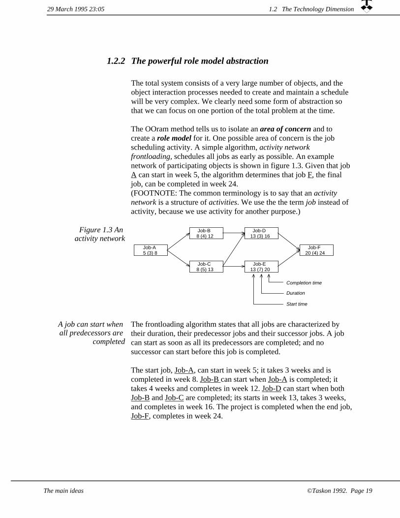
The OOram method tells us to isolate an area of concern and to create a role model for it. One possible area of concern is the job scheduling activity. A simple algorithm, activity network frontloading, schedules all jobs as early as possible. An example network of participating objects is shown in figure 1.3. Given that job A can start in week 5, the algorithm determines that job F, the final job, can be completed in week 24.(FOOTNOTE: The common terminology is to say that an activity network is a structure of activities. We use the the term job instead of activity, because we use activity for another purpose.)
Job-F20 (4) 24
Job-E13 (7) 20
Job-D13 (3) 16
Job-C8 (5) 13
Job-B8 (4) 12
Job-A5 (3) 8
Duration
Completion time
Start time
Figure 1.3 An activity network
The frontloading algorithm states that all jobs are characterized by their duration, their predecessor jobs and their successor jobs. A job can start as soon as all its predecessors are completed; and no successor can start before this job is completed.
A job can start when all predecessors are
completed
The start job, Job-A, can start in week 5; it takes 3 weeks and is completed in week 8. Job-B can start when Job-A is completed; it takes 4 weeks and completes in week 12. Job-D can start when both Job-B and Job-C are completed; its starts in week 13, takes 3 weeks, and completes in week 16. The project is completed when the end job,Job-F, completes in week 24.
29 March 1995 23:05 1.2 The Technology Dimension
The main ideas ©Taskon 1992. Page 19

Successor
Job
Job-D13 (3) 16
Predecessor
Job-B8 (4) 12
Job-A5 (3) 8
CompletionTime messages
early_completionearly_start
durationearly_completion
Figure 1.4 Identifying an object
pattern
The class abstraction does not help us understand the essence of the network in figure 1.3 All Jobs could in fact be instances of the same class. It is better to identify a pattern of objects which together capturean interesting phenomenon. In figure 1.4, we have focused on Job-E and isolated the object pattern consisting of Job-E, its predecessors (just one, Job-C in this case), and its successors (Job-F).
Object patterns abstracted into role
models
The object pattern is abstracted into a corresponding role model, where each pattern object is mapped on to a corresponding role. In our example, we see that this is a recurring pattern, and that any network can be constructed as a repeated overlay of these roles. (FOOTNOTE: Overlaying role models will be discussed in the next section on synthesis.)
The role model captures an archetypical pattern of objects and permitsus to study its essential static and dynamic properties. A Predecessor role has one interesting attribute: its early_completion time. The Job role has three interesting attributes: Its early_start time, its duration, and its early_completion time.
The OOram method supports a number of different views on the role model; each view highlighting some aspects of the model and hiding others. For example, figure 1.5 is a role model collaboration view. This view shows the roles, their attributes, and their collaboration structure.
The role model provides a more fine-grained control of message passing than the more common class or type. The role model specifiesnot only the messages that must be understood by an object (role), but also who are allowed to send the different messages. The collaboration view may optionally show some or all the messages thatone role may send to another, or the message interfaces can be presented in an interface view.
29 March 1995 23:051.2 The Technology Dimension
©Taskon 1992. Page 20 The main ideas

Figure 1.5 The essential roles for understanding the
frontloading scheduling algorithm
job pre suc job
Predecessor
early_completion
Job
early_startduration
early_completion
Successor
port for transmittingmessages to collaborator
The frontloading activity is specified as a sequence of messages flowing through the role model as shown in the scenario view of figure 1.6. The Predecessor objects send a message, CompletionTime,to the Job role. The Job computes its own early_completion, and reports it to all its Successor roles.
Predecessor Job Successor
CompletionTime
CompletionTime
Figure 1.6 Message scenario illustrating frontloading activity
If we open the Job role, we can study what takes place when it receives CompletionTime messages. This is illustrated in the method view of figure 1.7 We see that the method is triggered when the Job role receives the CompletionTime message. The method computes its own early_completion when all predecessors are ready, and the method finally reports the Job's completion time to its Successors.
Figure 1.7 Frontloading method
in Job roleJob Successor
CompletionTime
<Wait for all predecessor early_completion times>
<Record own early_start as latest predecessor completion>
<Determine early_completion>
<Report to all successors> CompletionTime
The notion of role modeling is a very powerful concept. We have created a single role model, the three diagrams are different views on one and the same model. The message received in figure 1.7 is the same as the first message in the scenario of figure 1.6. The message issent through the left port of figure 1.5, and we could have annotated the ports with the messages that can legally be sent through them.
29 March 1995 23:05 1.2 The Technology Dimension
©Taskon 1992. Page 21The main ideas

1.2.3 Separation of concern and Role model Synthesis
Divide and conquer is an important concept in all modeling practices. In the previous section, we created a role model for an interesting phenomenon, namely network frontloading.
The frontloading algorithm is just one of the many concerns that are relevant to shipyard scheduling and control. Another area of concern is the allocation of resources to the different jobs. A possible role model is shown in figure 1.8. The corresponding scenario is shown in figure 1.9; where the Job asks the Resource to allocate it, and the Resource answers the reserved time period.
Divide and conquer
Figure 1.8 Collaborators for
basic resource allocation
res
job
Job
planned_startdefault_duration
planned_completion
Resource
reservations
Job Resource
allocate The resource returnsthe reserved time slot
Figure 1.9 Scenario for basic resource
allocation
29 March 1995 23:051.2 The Technology Dimension
©Taskon 1992. Page 22 The main ideas

The advantage of this separation of concern is that we get manageable models. The disadvantage is that it can lead to a fragmented description of large problems, since each model describes only a limited aspect of the total problem. We meet this fragmentationproblem with role model synthesis, where we construct derived role models whose objects play multiple roles from several base role models.
Role model synthesis is one of the most powerful features of the OOram role model. All object oriented methods support class inheritance, where a derived class can be defined to inherit attributes and behavior from one or more base classes. In the OOram method, inheritance is lifted to the model level so that a derived model inherits the static and dynamic properties of one or more base models.
Synthesis: Objects play multiple roles
BOX: SynthesisThe antonym of analysis is synthesis, and we use the term role model synthesis to denote the construction of a derived model from one or more base models in a controlled manner:
synthesis: 1a: the composition or combination of parts or elements so as to form a whole... 1c: the combination of often diverse conceptions into a coherent whole. [Webster 77].
The use of role model synthesis permits us to build complex models out of simple ones in a safe and controlled manner. Dr. Philip Dellaferra of the Deutsche Telekom Research Center first introduced the "hat stand synthesis model" of figure 1.10. This figure, which illustrates scheduling with resources, highlights two important aspectsof synthesis. First, role models are combined vertically by letting theirobjects play multiple roles. Second, the integration between role models is through the methods that objects use to process incoming messages.
Resource allocationRole Model
Network frontloadingRole Model
Job-FJob-EJob-C
ResourceRole
JobRole
JobRole
PredecessorRole
SuccessorRole
a Resource
Figure 1.10 Synthesis specifies
that objects play several roles in a
coordinated manner
Role model synthesis gets its leverage from always seeing inheritancein the context of a "complete" pattern of collaborating objects. We
29 March 1995 23:05 1.2 The Technology Dimension
The main ideas ©Taskon 1992. Page 23

therefore inherit not only the characteristics of individual objects, but also the structure and behavior of the model as a whole. Figure 1.11 illustrates the two synthesis operations needed to derive a composite scheduling model from the frontloading and the resource allocation models.
Figure 1.11 Derived scheduling model
synthesized from two base models
suc job
res
job
suc job
res
job
job pre
job pre
Job
Resource
Predecessor Job Successor
Predecessor Job Successor
Resource
Frontloadingmodel
Resourceallocationmodel
Derived (composite) model
The dependencies between synthesized role models are expressed in the methods of the objects. The behavior of an object when receiving a message in the context of a role in one role model may be modified because it is also playing some other role. In figure 1.12, the method for computing early completion time has been modified from just adding the duration to asking the resource for allocation.
Methods synthesize behavior
29 March 1995 23:051.2 The Technology Dimension
The main ideas©Taskon 1992. Page 24

Figure 1.12 Integration through
scheduling method
Job Successor Resource
CompletionTime
<Wait for all predecessor early_completion times>
<Record own early_start as latest predecessor completion>
<Determine early_completion> allocate
^reservation
<Report to all successors> CompletionTime
The Job determines itscompletion time throughResource allocation.
The role models are integrated through the Allocate message to the Resource role.
In the ideal case, the correct functioning of a base model will automatically be retained in a derived model after synthesis. Such safe synthesis is very valuable, since it permits the reuse of a correct role model with a minimum of hassle. Indeed, if we think of a role model that is solely created by the safe synthesis from a number of correct base models, we would create it only if we needed it for explanation purposes.
Safe synthesis is essential for designing a truly global data processing system. Ideally, we should not need to construct the overall system model with all its details. An overall model should be expressed in terms of high-level base models; a high-level base model in terms of low-level base models. Every base model should be independent in the sense that its correctness will be preserved if it is applied with safesynthesis.
Safe synthesis
In unsafe synthesis, the derived model has to be analyzed in total before we can assume it to be correct. You might believe that unsafe synthesis is something to be avoided like the plague, but we find it useful when we analyze some limited phenomenon in order to understand it and communicate our findings. (Even if synthesizing theresource model into a wider context were unsafe, doing so could still help us create a derived model to understand the phenomenon. But wewould have to recheck the complete derived model). In general, we permit unsafe synthesis when we analyze a relatively limited area of concern. Safe synthesis is required when we want to create models that can be reused in a general context.
Unsafe synthesis
29 March 1995 23:05 1.2 The Technology Dimension
©Taskon 1992. Page 25The main ideas

Hierarchical decomposition is a commonly used device for dividing a complex problem into a number of simpler ones. Hierarchical decomposition is easily achieved in object systems by means of the encapsulation property. An object can contain any amount of complexity within itself, including a complex object structure, without exposing this complexity. But there is also a weakness with hierarchical decomposition: true hierarchies are rarely found in the real world.
Synthesis, a very powerful notion
Role model synthesis is a powerful notion because it facilitates the decomposition of large problems in arbitrary structures. The resource model of figure 1.8 can in one sense be regarded as subordinate to the frontloading model of figure 1.5. But the resources are primary phenomena if we study the shipyard as such, and in this context the jobs may be seen as subordinate to the resources. Other superimposed structures abound in a typical enterprise. Examples are project organizations, professional structures and various ad hoc structures. If these structures are independent, all is well. If they are dependent, rolemodel synthesis enables us to model the dependencies between them.
OOram implementation links role models to computer programs
1.2.4
In a nutshellThis section has been written for computer programmers who are familiar with an object-oriented programming language. Nonprogrammers may safely skip it.
Any role model can be promoted to an object specification. Real world models may be implemented as office procedures or as computerbased simulation models. Object-oriented models are implemented as programs to create executable specifications or to create application programs.
In all our work with objects over the past 20 years, we have found thata programming language is ideally suited to express a detailed definition of the system under consideration. We have likewise found that a programming language is useless for expressing an overview of the system; for describing the structure of objects and their interaction. So there is nothing resembling code in the production control system of [Ree 77], only attempts at expressing the static and dynamic interdependencies between objects.
The essence of an object system is not easily seen from the
code
29 March 1995 23:051.2 The Technology Dimension
The main ideas©Taskon 1992. Page 26
The objects of figure 1.3 play one or two roles: job A plays the Predecessor role; role F plays the Successor role; and all the other objects play all three roles.
The simplest way to implement a role model is to define a single class, e.g., Job1, that implements all three roles. We choose a programming language, e.g., C++ or Smalltalk, and implement a single class which covers all three roles. The class will have instance variables for the attributes and for the collaborators: early_start, duration, early_completion, predecessors and successors. It will have methods to enable its instances to handle the CompletionTime message and other messages not mentioned here.
A single class implements all three
roles
Object specification models
Since objects are meaningless when seen in isolation, we prefer to describe object types in the context of their collaborators. An object specification model is the role model of a structure of objects that we have implemented or intend to implement. A role in an object specification model is called an object type, which is a specification of a set of objects with identical externally observable properties. An implementation of an object type is called a class in conformance with common object-oriented programming terminology.
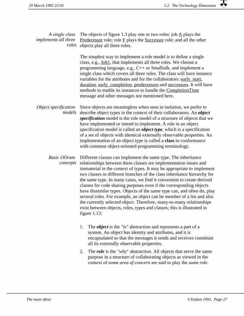
Different classes can implement the same type. The inheritance relationships between these classes are implementation issues and immaterial in the context of types. It may be appropriate to implementtwo classes in different branches of the class inheritance hierarchy for the same type. In many cases, we find it convenient to create derived classes for code sharing purposes even if the corresponding objects have dissimilar types. Objects of the same type can, and often do, playseveral roles. For example, an object can be member of a list and also the currently selected object. Therefore, many-to-many relationships exist between objects, roles, types and classes; this is illustrated in figure 1.13:
Basic OOram concepts
The object is the "is" abstraction and represents a part of a system. An object has identity and attributes, and it is encapsulated so that the messages it sends and receives constitute all its externally observable properties.
1.
The role is the "why" abstraction. All objects that serve the same purpose in a structure of collaborating objects as viewed in the context of some area of concern are said to play the same role.
2.
1.2 The Technology Dimension29 March 1995 23:05
©Taskon 1992. Page 27The main ideas
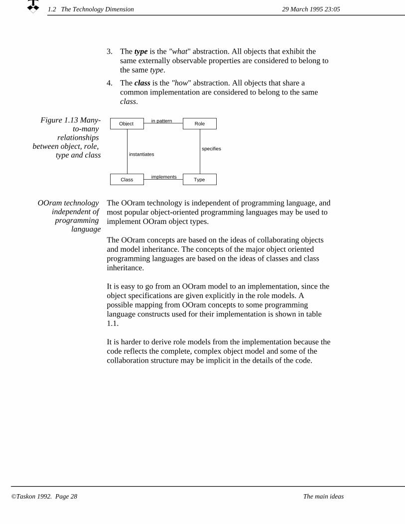
The type is the "what" abstraction. All objects that exhibit the same externally observable properties are considered to belong to the same type.
3.
The class is the "how" abstraction. All objects that share a common implementation are considered to belong to the same class.
4.
Figure 1.13 Many-to-many
relationships between object, role,
type and classspecifies
implementsClass Type
RoleObject in pattern
instantiates
OOram technology independent of programming
language
The OOram technology is independent of programming language, andmost popular object-oriented programming languages may be used to implement OOram object types.
The OOram concepts are based on the ideas of collaborating objects and model inheritance. The concepts of the major object oriented programming languages are based on the ideas of classes and class inheritance.
It is easy to go from an OOram model to an implementation, since the object specifications are given explicitly in the role models. A possible mapping from OOram concepts to some programming language constructs used for their implementation is shown in table 1.1.
It is harder to derive role models from the implementation because thecode reflects the complete, complex object model and some of the collaboration structure may be implicit in the details of the code.
29 March 1995 23:051.2 The Technology Dimension
The main ideas©Taskon 1992. Page 28

Table 1.1 Mapping OOram models to
programs
OOram Smalltalk C++
Role Model - -
Role Object Object
Object Specification, Type Class Class
Port Variable Pointer data member
Interface Protocol Abstract class or protocol class
Message Message Function call
Method Method Member function
Derived model Subclass Derived class
Base model Superclass Base class
Single and multiple inheritance
All object-oriented programming languages support some form of inheritance. (Languages missing this feature are usually called object based languages.) Some commonly used languages such as Smalltalkonly permit single inheritance; i.e., a class may only have a single superclass. Other popular languages such as C++ support multiple inheritance; i.e., a class may be derived from several base classes.
The class inheritance structure of an object-oriented program may be designed for two entirely different and often conflicting purposes. Weusually design it to reflect the structure of our concepts, and it will then map nicely on to the role model synthesis structure. But some class structures are designed just to share common code irrespective of conceptual relationships. Both purposes are legitimate and useful; both purposes may be exploited in a well-designed program. Since our focus is on the modeling of concepts, OOram synthesis always reflects the conceptual structure.
Class inheritance used for concept
specialization and code reuse
Figure 1.14 illustrates how some of the models in the role model synthesis structure are promoted to object specifications and implemented as a corresponding set of coordinated classes. Object Specification 2 inherits from Object Specification 1, this indicates thatClass Set 2 may profitably be derived from Class Set 1.
Class inheritance structure may be
mapped on the role model synthesis
structure
29 March 1995 23:05 1.2 The Technology Dimension
©Taskon 1992. Page 29The main ideas

Figure 1.14 The class inheritance structure can be
fashioned after the model synthesis
structureClass Set 1Object Specification 1
Role Model 3
Role Model 2
Role Model 1
Object Specification 2 Class Set 2
Implemented by
Classinheritance
Role model synthesis
Implemented by
Role model synthesis
OOram reuse technology1.2.5
OOram reuse The OOram method exploits object technology to support the controlled reuse of proven components. This facilitates the creation ofinformation environments tailored to the needs of the particular actors,reduces production costs and lead time, increases system reliability, and protects critical resources with mandatory access through proven components.
The single most highly promoted advantage of the object paradigm is its support for reuse, but this is also the area of the deepest disappointments.
Reusable components imply
repeat business
Ralph Johnson has been quoted as saying that nothing can be reused before it has been used. Reuse requires repeat business so that reusable components can be identified, created, installed in a software development environment, and finally reused. Investment is needed tocreate the reusable components, the only payoff is through their actualuse.
A reusable component has a supplier and one or more consumers. Thesupplier and consumers may be the same people; they must still createthe reusable component before they can use it. More commonly, the suppliers and consumers will be different people or even different organizations.
Reusable components have
suppliers and consumers
Both the creation and the application of reusable components depend upon appropriate solutions along all three dimensions of figure 1.1 fortheir success.
Successful reuse involves all three
dimensions
1.2 The Technology Dimension 29 March 1995 23:05
The main ideas©Taskon 1992. Page 30

1. Technology. The creator of a reusable component must choose technology that is not only appropriate for the problem, but also appropriate for the people who are going to apply it. We will heredistinguish between patterns and frameworks, they are best applied by professional developers. In the advanced section, we will discuss composition and duplication; technologies that are well adapted to support non-professionals such as sales consultants and end users.
2. Organization. The benefits of reuse can only be achieved throughan appropriate organization. We suggest the idea of a value chain,where the people on one level build on the results from the layer below and deliver results to the layer above. The results deliveredto the layer above are their production facilities including reusable components. This is in contrast to the deliverables from the various stages of the project work process; these deliverables are parts of the total project deliverables. For this reason, we regard the value chain as orthogonal to the work process on each layer.
3. Process with deliverables. The proper application of reusable components should be an integral part of the development work process. The success criterion for the developers must include reuse; measuring programmer productivity by lines of code produced is finally shown to be counter-productive. The development of a reusable component is a product development that must be guided by an appropriate work process.
A pattern tells the reader how to solve
a problem
In the early seventies, the architect Alexander (FOOTNOTE: [Alexander 79]) proposed patterns as an interesting way for communicating important ideas among professionals. An enthusiastic group of computer professionals have adapted these ideas to our field,and a book on Design Patterns has been published (FOOTNOTE: [GaHeJoVli 95]).
In the Alexander sense of the word, a pattern is a specification of a problem and and a guide to its solution. For problems in object oriented design, the solution frequently involves an archetypical structure of objects. In these cases, the solution can often be describedin terms of a role model. But this is to be construed as a communication device only, and not as a canned solution.
1.2 The Technology Dimension29 March 1995 23:05
©Taskon 1992. Page 31The main ideas

Some professionals are using the term pattern in a different meaning; they take it to mean an archetypical structure of collaborating objects, very similar to what Booch has called a mechanism and what we haveformalized into the role model abstraction. We use the term pattern inthe original sense to denote a guide to the solution of a problem; and we use the term object pattern to denote an archetypical structure of objects. We give object pattern a precise meaning by defining it as an instance of a role model.
A framework is a canned solution
A framework is usually defined as a collection of classes that togethersolve a general problem, and that are intended for specialization through subclassing. The main difference between a framework and a pattern is that while the pattern tells the reader how to solve a problem, the framework provides a canned solution.
Role models are admirably suited for describing frameworks. The rolemodel defining the framework functionality can easily be synthesized into an application model. This model inherits all static and dynamic properties and possible constraints from the framework role model.
Example: The activity network as a
specialization of a graph
As an example, let us return to the network planning example of figure 1.3. The model we presented was just a small fragment of a realmodel. It did not include the insertion and removal of jobs; it did not include protection against cycles in the network; and it did not providefacilities for setting and modifying job attributes. All these details could probably be omitted at the analysis stage, but would at least have to be taken seriously at the design stage.
Most of the details are not specific to the activity network; they are common to a broad group of structures called Directed, Acyclic Graphs (DAGs). An appropriate pattern would give us access to accumulated experience with these structures: it would identify the objects, give all important algorithms, and provide practical hints as tothe best solutions under different circumstances.
A graph pattern tells us how to design a
network
A graph framework provides a solution
An alternative reusable component would be a framework for directed, acyclic graphs. This framework would include classes for the objects, these classes would have programs for the insertion and removal of nodes and for protection against cycles in the network. They would probably not include facilities for setting and modifying object attributes, since this will typically be done in the derived models.
29 March 1995 23:051.2 The Technology Dimension
The main ideas©Taskon 1992. Page 32
The component user is fortunate
Consider that we should meet the activity planning problem for the first time. We study the problem and try to identify key processes and key actors. We study examples such as figure 1.3 to better understand the phenomenon. We tentatively create a role model such as the modelshown in the views of figure 1.5 through 1.7. But how do we know that we have chosen appropriate roles? How do we know that we haven't overlooked some essential part of the problem? The answer is that we can hope for the best and suspect the worst, but we just cannotknow. We must expect to revise our ideas several times as we study the problem and analyze its possible solutions.
The developer who finds an applicable reusable component is a truly fortunate person. He can build on the mature wisdom and experience of people who have not only solved similar problems in the past, but who have actually studied a number of different solutions and who have carefully recorded their competence.
nod
own
suc nodnod pre
Owner
Pred Node Succ
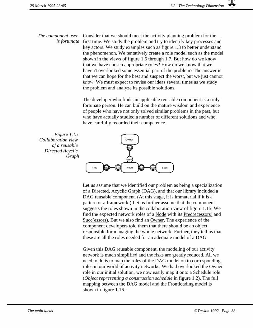
Figure 1.15 Collaboration view
of a reusable Directed Acyclic
Graph
Let us assume that we identified our problem as being a specializationof a Directed, Acyclic Graph (DAG), and that our library included a DAG reusable component. (At this stage, it is immaterial if it is a pattern or a framework.) Let us further assume that the component suggests the roles shown in the collaboration view of figure 1.15. We find the expected network roles of a Node with its Pred(ecessors) and Succ(essors). But we also find an Owner. The experience of the component developers told them that there should be an object responsible for managing the whole network. Further, they tell us that these are all the roles needed for an adequate model of a DAG.
Given this DAG reusable component, the modeling of our activity network is much simplified and the risks are greatly reduced. All we need to do is to map the roles of the DAG model on to corresponding roles in our world of activity networks. We had overlooked the Ownerrole in our initial solution, we now easily map it onto a Schedule role (Object representing a construction schedule in figure 1.2). The full mapping between the DAG model and the Frontloading model is shown in figure 1.16.
29 March 1995 23:05 1.2 The Technology Dimension
The main ideas ©Taskon 1992. Page 33

nod pre
suc nod
suc nod
nod
own
nod
own
nod pre
Owner
Pred Node Succ
Schedule
Predecessor Job Successor
Frontloading model
DAG(Directed Acyclic Graph)model
Figure 1.16 DerivingActivity Network
from reusable Directed Acyclic
Graph
A good pattern explains all essentials, clearly and completely. It is also concise; the reader of a pattern is assumed to be an expert.
A good framework hides as much complexity as possible, making functionality visible to the application programmer on a "need to know" basis. Its visible functionality is published as a base role modelto be synthesized into the application. In our example, the DAG model is synthesized into the Frontloading model in figure 1.16, automatically giving it all the required network maintenance functionality.
The dynamic behavior exemplified by the scenario of figure 1.6 could either be a feature of the derived model, or it could be a specialization of a general graph traversal algorithm defined in the base model.
The creation of reusable components share many of the general properties of product development, and the life cycle may conveniently be divided into five phases:
A reusable component is a
product
1. Market analysis. The developer must understand the needs of the potential users and balance these needs against the costs of alternative solutions. The developer must also understand the potential users' working conditions to make the reusable component practically applicable.
29 March 1995 23:051.2 The Technology Dimension
The main ideas©Taskon 1992. Page 34
Product development. The reusable component must be designed, implemented, and tested in one or more prototype applications.
2.
Product packaging. Documentation is an important part of a packaged reusable component. The documentation includes work processes for the application of the component; installation procedures; and technical information.
3.
Marketing. The users of the reusable component must be informed and persuaded to apply it.
4.
5. Application. The reusable component is applied and must help its users to increase the quality of their products and reduce their expenditure of time and money.
Costs accumulate in the first four phases. The cost of the resulting assets is written off against the value created in the fifth and final phase.
1.2.6 Comparison with other methods
The Object Modeling Technique, OMT, was developed by James Rumbaugh and others at General Electric Research and Development Center (FOOTNOTE: [Rumbaugh 91]). OMT supports three basic models: The object model, the dynamic model, and the functional model.
The OMT object model describes the object types and their relationships. It is an extended Entity-Relationship model with classesthat can contain both attributes and operations. It is possible to describe object instances with instantiation relationship to classes. Associations between classes can be of different cardinalities and can have attributes.
The OMT dynamic model describes when things happen. The dynamic model is based on the powerful statecharts proposed by Harel (FOOTNOTE: [Harel 87]). The transitions between states take place on events and can be associated with an action. There can also be actions associated with states.
The OMT functional model describes what is happening. It is based on traditional data flow diagrams. They are supposed to be used to
The OMT models canbe expressed as
OOram views
29 March 1995 23:05 1.2 The Technology Dimension
The main ideas ©Taskon 1992. Page 35

show transformations on values, and not to describe object interactions.
The information described in the three OMT models is almost fully described within the OOram role model. The OMT object model is best seen in the collaboration view; the OMT dynamic model is best described in the OOram state diagram view; and the OMT functional model corresponds to the process view. There are some differences; most of them due to the coherent concepts of the OOram model. The OOram state diagram is a simpler form than the Harel state chart; all events are message interactions, and all actions are method activations. The OOram process view shows data transfer aspects of object interaction, all data are stored within objects and transferred as message parameters.
The Booch method has its basis in object-oriented design from the Ada world. However, the second edition of the book (FOOTNOTE: [Booch 94]) is adapted to C++. The Booch method is the most comprehensive method with respect to the modeling of language-oriented design features such as parameterisized classes and public, protected, and private access.
The basic concepts are founded on the traditional object-oriented programming concepts: object, class, and inheritance. The logical model consists of class diagram, object diagram, interaction diagram,and state diagram. The physical model consists of module and process diagrams.
The Booch models can be expressed as
OOram views
The information in the Booch class diagram can be expressed in the OOram semantic and collaboration views. There is more detail in the Booch diagrams than normally described in the OOram view; e.g., visibility between classes, metaclasses, and parameterized classes. Instantiation of objects from classes is not described in the OOram role model, only instantiation as one of the functions of a method as seen in a scenario view.
The Booch object diagram describes a sequence of messages sent between objects. Equivalent information can be found in the OOram scenario, message interfaces can also be found in the collaboration view and special interface views.
As was the case for OMT, the Booch state diagram is based on the Harel statecharts. The OOram finite state diagrams cover roughly the same information, with the caveat that the OOram state diagram is strictly object oriented with all events being mapped as message interactions and all actions as (partial) method invocations.
1.2 The Technology Dimension 29 March 1995 23:05
©Taskon 1992. Page 36 The main ideas

Information that in the Booch notation is separated between class and object diagrams is merged within a single, comprehensive OOram rolemodel. The role model is independent of programming language and the views do not match the rich expression of implementation details exhibited by the Booch notation. An OOram modeler would put this kind of information into comments associated with the different model entities.
For the Booch physical model there is no direct equivalent in OOram. The OOram module is strictly defined in terms of modeling-in-the-large; it is independent of any programming language constructs. The OOram perspective is that interfaces are associated with an object. This can be mapped directly into classes in an object-oriented programming language, or supported by a distributed object infrastructure. Such an infrastructure would support dynamic configuration at runtime, and it is not necessary with a particular physical mapping.
The OOSE models can be expressed as
OOram views
The OOSE methodology has its origin in work with telecommunication applications and SDL. The initial ideas for object-oriented adaption of the methodology was presented by Ivar Jacobsonin 1986 and -87. The OOSE methodology (FOOTNOTE: [Jacobson 92]) is a scaled down version of the full methodology which is called ObjectOry.
The most famous aspect of this methodology is its use of use-cases as a glue for tying together all models. A use-case is a set of interactionsbetween the environment and the system, followed from beginning to end. A use case can be seen as a set, where the members are actual sequences of interactions. A use-case is thus more than a scenario, it is all the possible scenarios that can be the result of a user stimulus onthe system.
The OOram method supports use-cases under the name of OOram activities. Activities are an integral part of the OOram role model concepts, and are supported through aggregation and other synthesis operations. Use cases are therefore fully supported in the OOram method.
29 March 1995 23:05 1.2 The Technology Dimension
©Taskon 1992. Page 37The main ideas

The RDD models canbe expressed as
OOram views
Responsibility Driven Design, RDD, is one of the few published methodologies with a pure object-oriented origin (FOOTNOTE [Wirfs-Brock 90]). It is based on experiences from object-oriented programming in Smalltalk done at Tektronix Labs, Software Productivity Technologies, in the period from 1983 to 1989 -- while Tektronix was the only vendor of specialized Smalltalk-based workstations.
The central idea of the RDD method is to divide the responsibility of the total system into the responsibilities of the different classes in a systematic manner.
Like RDD, the OOram method has a pure object-oriented origin. All concepts described in the RDD method are fully supported in the OOram method. The difference is that the roles take the place of the classes, and that roles are always considered in the context of their collaborators in the role model.
OOram models can replace E-R models,
but we need good reasons to do so
The powerful relational model is well known in the database community. In this model, data are represented as records in tables. (Or more precisely: data are represented as tuples in relations.) Relational data models are often designed in terms of entity-relationship (E-R) diagrams (FOOTNOTE: [Chen 76], [Elmasri 94]). Most of the information shown in an E-R diagram can be shown in an OOram collaboration view.
We once did a small study to identify the benefits of the OOram role model over the traditional E-R model. We had access to the data model of the accounting system of the University of Oslo, and began translating it into role modeling terms. We found two very clear conclusions from this exercise: (a) we could create a role model collaboration view which was very similar to the E-R diagrams; and (b) we would never dream of creating such an object model!
There were two reasons why an analyst trained in the object paradigm would not come up with an object model resembling the existing E-R model. First, the E-R model contains a great number of details that will be the responsibility of various objects and, therefore, invisible outside these objects. Second, the scope of the E-R model is limited tostatic data descriptions. With an object oriented approach, we naturally extend the scope by asking new questions: who are interested in the data, what are the operations they want to perform on the data, and what kind of behavior should be supported by the model?
29 March 1995 23:051.2 The Technology Dimension
©Taskon 1992. Page 38 The main ideas

Our conclusion from this small and informal study was that an OOramrole model can indeed take the place of an Entity-Relationship model, but that we should only do so if we need the added behavioral power of objects.
One of the important characteristics of objects is that an object has identity. An object retains its identity throughout its lifetime and regardless of changes to its data contents. Furthermore, there has never been and will never be another object with the same identity.
Object identity essential for
describing dynamic behavior
The notion of object identity makes it possible to reason about the dynamic aspects of system behavior; giving the object model additional leverage not available in the relational model. We study notonly the object characteristics needed to fulfill a certain purpose, but also exactly how the objects interact to achieve this purpose.
The main models of the currently popular methodologies are based onthe class abstraction. The fundamental weakness of this abstraction is the same as the weakness of the relational model: it describes classes as sets of objects, and relations between objects in terms of anonymous instances.
The OOram role modeling concepts bring all the different modeling concepts together into a coherent whole. The role model is a precise description of an object pattern where its objects are abstracted into the roles they play in the context of the pattern. Roles are archetypicalobjects, so the role model can combine data-centered and function-centered descriptions.
The OOram role modeling concepts bring it all together
Roles have class-like properties
Like a class, a role is a description of a set of objects. But there is a crucial difference: The class describes the set of objects that exhibit common characteristics. The role describes the set of objects which occupy the same position in a pattern of objects. We can describe the semantics of the roles and their relation in the context of the role model; we can describe the attributes that must be exhibited by all objects playing the roles; we can describe how the total responsibility is allocated to objects playing the different roles; and we can describe the sets of messages a role may send to another role.
Like objects, roles have identity so that we can reason about their cooperative behavior. We use scenarios to describe typical sequences of message flows. Process diagrams show how data flows between roles. Finite state diagrams show how each role changes its state in response to messages received from other roles.
Roles have object properties
1.2 The Technology Dimension29 March 1995 23:05
The main ideas ©Taskon 1992. Page 39

OOram inheritance tells the complete
story because it applies to complete
models
There is no point in using inheritance to derive a class with added functionality if we do not at the same time derive another class which uses this added functionality. Role model inheritance not only exhibitsthe inheritance relationships between individual classes; they explain how the whole story told by a role model is retold by the roles of the derived model. So the OOram inheritance is done in the context of role models: a role model can inherit another role model and thus build on its functionality.
OOram technology facilitates systematic
reuse
There are important practical consequences of the role model coherence. A complex reality can be represented as a complex object structure and described as a number of much simpler role models. General phenomena can be described as general role models, these role models can be reused as building blocks for the creation of application system models. If the general role models are implemented as sets of coordinated classes, these frameworks can be reused in a safe and controlled manner in the design and implementation of application programs.
OOram technology facilitates more
effective organization
The technology for systematic reuse provided by OOram role modeling makes it possible to organize application system development in novel ways. Extensive and systematic reuse lets us create large applications in small projects. A prerequisite is that suitable reusable components are available: systematic reuse requires investment in reusable assets.
29 March 1995 23:051.2 The Technology Dimension
©Taskon 1992. Page 40 The main ideas

Process with Deliverables1.3
In a nutshellA work process describes the steps that need to be performed in order to reach a given goal. The steps are usually described as if they were performed sequentially, while in reality they are performed in an opportunistic sequence and often in parallel. Documentation and other deliverables are the concrete results of the work process. It is often useful to pretend that the deliverables are the results of a rational work process because this makes them easier to read and understand.
There are work processes on many different time scales. We have found it convenient to distinguish between three: creating a model, creating an application, and creating a reusable component.
A work process is a sequence of steps that need to be performed to reach a specified goal. The process itself is almost invisible to all but the people who actually perform it. The process steps should thereforebe intimately associated with the deliverables that constitute their concrete results. The deliverables can be computer programs, formal models, or informal descriptions.
A work process describes the steps needed to reach a
goal
Processes on different time scales
Processes can be on different time scales, ranging from short processes for the solution of specific details to very long term processes covering the evolution of reusable assets. We find it convenient to distinguish between the following processes:
The model creation process focuses on how to create a model or some other manifestation of thoughts for a certain phenomenon. Examples are processes for creating a role model, for performing role model synthesis, and for creating object specifications.
1.
The system development process covers the typical software life cycle. It consists of the steps from specifying users needs to the installation and maintenance of the system that meets these needs.
2.
3. The reusable assets building process is the least mature software engineering process, but we expect it will be an essential contributor to future productivity and quality. Our focus is on the continuous production of several, closely related systems; where we build on a continuously evolving set of reusable components. Creating a system will mainly be a case of configuring and reusing robust and proven components; possibly adding a few new components to complete the system.
29 March 1995 23:05 1.3 Process with Deliverables
The main ideas ©Taskon 1992. Page 41

The processes are opportunistic and
iterative
The work processes on all three levels are iterative and the deliverables evolutionary. The goal is to minimize the risk by focusing the most critical parts in the early iterations.
Many managers dream of the ultimate work process that will ensure satisfactory solutions from every project. We believe that this dream is not only futile; it can even be harmful.
Documentation is by its nature linear and must be strictly structured. Software development processes are by their nature creative and exploratory, and cannot be forced into the straightjacket of a fixed sequence of steps. In an insightful article, [Parnas 86] states that manyhave sought a software process that allows a program to be derived systematically from a precise statement of requirements. Their paper proposes that although we will not succeed in designing a real productthat way, we can produce documentation that makes it appear as if thesoftware was designed by such a process.
The documentation issequential
The sequences of steps we suggest in the following and in the rest of the book are therefore to be construed as default work processes and suggested documentation structures. We also believe that you will have to develop your own preferred sequence of steps, but you may want to take the steps proposed here as a starting point.
1.3.1 Introduction to the model-creation process
How should you go about describing a phenomenon in a role model? In the general case, we suggest the following eight steps for creating arole model. Each step results in a deliverable, which is a view on the role model. The relative importance of these views depend on the purpose of the model.
Eight steps for developing a role
model
The steps are performed iteratively until the role model is adequately defined. Steps (4) and (5) are performed in parallel. It is often easier to see what needs to be done than to identify the actors, but both need to be specified in an object-oriented model.
Determine the Area of Concern(1)
Understand the problem and identify the nature of the objects(2)
Determine Environment roles and Stimulus/Response(3)
(4) Identify and understand the roles
29 March 1995 23:051.3 Process with Deliverables
©Taskon 1992. Page 42 The main ideas

(5) Determine the message sequences
Determine the collaboration structure(6)
Determine Interfaces(7)
(8) Determine the role behavior
With the OOram method, you can describe your analysis and design in a single role model or in a number of related models. There are general process guidelines for creating the individual models, and for breaking complex situations into smaller models that "are so simple that there are obviously no deficiencies".
Introduction to the system development process1.3.2
We will here focus on medium-term processes that cover the development of individual systems. Some important models are indicated in figure 1.17. We zoom back to study the system environment at the top level; we zoom in to study implementation details at the bottom level. The relationships between the models can be made formal or informal. Formal model relationships lead to a seamless system description, but it may be hard to change. Informal model relationships are easier to handle, but can hide dangerous system inconsistencies.
1.3 Process with Deliverables29 March 1995 23:05
The main ideas ©Taskon 1992. Page 43

Systemimplementation
Systemdesignmodel
Systemrequirementsmodel
Systemuser
model
Systemof objects
Figure 1.17 Typical descriptions on
different levels of abstraction
A System User model describes the system environment. Most interesting systems are open systems. They will be installed in an environment that will influence the system and be influenced by it. The environment can be a human organization as is the case forbusiness information systems, or it can be some equipment as is the case for embedded systems. Whatever its nature, we need to understand the system environment, and describe it in the System User model.
1.
2. A System Requirements model describes the system as seen fromits environment. There are two important models: a model of the interface between the system and its environment; and a model of the system logic as perceived by its users. The relationships between these two models and the the System User model are interesting. The interface model describes the tools employed by the users to perform their tasks; and the system logic model describes the subject or universe of discourse of the activities describes in the user model.
A System Design model describes the system as seen by its developers. They elaborate the System Requirements models and add technical details of interest to the implementors. Their main features are the system components and their interaction.
3.
29 March 1995 23:051.3 Process with Deliverables
The main ideas©Taskon 1992. Page 44

4. A System Implementation model is a precise description of the system including all the details needed to make it operational. In the case of computer-based systems, we express it in a programming language. In the case of human organizations, we express it as a set of business procedures.
The process is opportunistic and
iterative
It is not our intention that figure 1.17 shall suggest a classical waterfall process. The figure shows the main models and the relationships between them. The process will be opportunistic, incremental, and iterative.The four system descriptions represent four different levels of abstraction. The documentation deliverable will often be organized top-down. The actual process will proceed from top to bottom; from bottom to top; and from the middle outwards. Wecall it the yo-yo approach to system development.
Other methodologies recommend system models resembling the four presented here. The OOram method does not enforce a particular set of models or a particular work process. On the contrary, we believe that the work process and deliverables have to be tailored to the nature of the problems; the preferred programming language; the traditions and regulations of the enterprise; the available tools and other development facilities; and the experience and preferences of the team members. If you have your own, proven process, we urge you to stick to it and apply the OOram concepts and notation as a framework for your own object-oriented methodology.
Introduction to the reusable assets building processes1.3.3
Everything changes! It is popular to claim that in our modern society, change is the only constant factor. Enterprises have to be able to adapt to an ever changing environment.
We believe this to be both true and misleading. It is true in the sense that an enterprise has to keep changing to adapt to its changing environment. It is also true in the sense that it has to change the core of its operations to accommodate the transition from manual to computer-based information processing; that it has to move its rule-based operations from people to computer; and that it has to cultivate the creativity, responsibility, and problem-solving capabilities of its human staff.
29 March 1995 23:05 1.3 Process with Deliverables
The main ideas ©Taskon 1992. Page 45

It is misleading in the sense that everything just cannot change all the time. So the challenge to the evolving enterprise is to identify what can be kept stable and what has to be kept fluid. The stable parts forman infrastructure on which it can build a light and rapidly changing superstructure.
Changing software, fixed components
Software development is a case in point. Effective software development can only be based on extensive reuse. But reuse implies repeat business, and we never need develop exactly the same piece of software twice. So we have to identify a family of software products that we want to become our specialty, to identify common elements inthis family, and to develop resuable components for these elements. This will enable us to fulfill a dream shared by many software developers: we will be able to develop large and reliable systems in small and effective projects.
CollectionofExperience
Fountainofproduction
END USER
Pool of reusable assets
Forward engineeringProducing revenue
Reverse engineeringInvesting inreusable assets
Figure 1.18 The Fountain Model for
Reuse
Figure 1.18 illustrates that we have two kinds of activities working on two different time scales. Forward engineering, where we produce new results for the end users. The success criterion of these activities is that they satisfy user needs and thus produce value (and possibly revenue). Reverse engineering is an asset-building activity. It works on a longer time scale than forward engineering when it analyzes the products produced and finds more effective ways of producing such products in the future.
29 March 1995 23:051.3 Process with Deliverables
©Taskon 1992. Page 46 The main ideas

The challenges to effective reuse are mainly organizational. The next section is devoted to these problems and their solution.
29 March 1995 23:05 1.3 Process with Deliverables
©Taskon 1992. Page 47The main ideas

Organization1.4
In a nutshellReuse is currently applied almost exclusively to software. This section is of general interest, however, because several of the OOram reuse opportunities are applicable to all kinds of object-oriented models. Reuse is currently almost exclusively applied to software, but we have also applied reuse technology to the design of organizations with great success.
Some people have believed that the inheritance and encapsulation properties of object orientation automatically make all objects into reusable components. This is wrong and has caused many disappointments. Resources have to be invested in theircreation, and value is only created when they are successfully applied for a valuable purpose.
Few, if any, interesting developments are done by single persons working in isolation. The organization dimension is concerned with how to organize a team of people who work together towards a common goal. Organizations come in many sizes and have widely different life spans. We organize a few people to create a certain model, and we organize several people to perform a complete project.
The premise of this book is that we will never be able to produce high quality software efficiently in the general software job shop, just as a blacksmith will never be able to produce a high quality car in his smithy. We expect an effective car factory to turn out cars and cars only. We should also expect an effective software production facility to turn out a particular family of software only.
We must change from a job shop to anindustrial approach
to software production
We deliberately organize a number of people, called actors, with different resources, skills, responsibilities and authority for the satisfaction of customer requirements. The actors reuse concepts, designs and software modules to enable the combination of high investment in quality and efficiency with low cost to the individual user.
Industrial software production
Our approach is an essentially industrial approach to software production, even if the software industry will be materially different in culture, organization, and methods from the traditional industries. Ifyou do not like the term industrial in this context, you probably think of all the negative aspects of industrialization. We here prefer to focuson the positive aspects, the ability of industrial organization to consistently deliver products of high quality and low cost.
29 March 1995 23:051.4 Organization
The main ideas©Taskon 1992. Page 48

In a mature software industry, many different human actors will work together to provide end users with sophisticated functionality. We introduce the idea of a multilayered value chain, where the people in each layer build on the results from the layers below it and deliver results to the layer above them. The actors on each level have their own unique responsibilities, spheres of competence and success criteria.
The value chain
It is important to cast the value chain so that the actors on each level can focus on their main business and not be burdened with details thathave been solved on the layer below them.
Industrial activity is a many-faceted endeavor. We will need facilities management; finance and accounting; marketing and sales; production planning and control; product specification, design and production. Our context is the industrialized provision of software to individual users or groups of users. We focus on the technical aspects of specification, design and production; and put special emphasis on basic concepts and their practical applications.
The success of industrialized software production will be due to the following four key characteristics:
An effective software production facility must be specialized. An industrial facility is carefully tuned to the effective creation of its products. You would expect a group which produces compilers only to be more effective than a group which produces all kinds of software, so you have to choose your specialty and stick to it.
1.
Reuse is the only known way to achieve satisfactory quality and efficiency. Reuse permits the repeated application of proven solutions and their continuous refinement. It is an axiom that a programmer doesen't often get it right the first time; so you should observe the use of your software and give it a chance to mature through successive improvements. For mass products, it means that you produce a steady stream of new releases; for customized software, it means that you build an inventory of reusable components and improve them over time. In both cases, stability and your long-term commitment are essential.
2.
29 March 1995 23:05 1.4 Organization
©Taskon 1992. Page 49The main ideas
Work and responsibilities must be divided along a vertical value chain. A car manufacturer designing a new car model does not start by trying to define "What is a car?" The design team has been designing cars for years and can concentrate on the finer details of the new model's specifications. Further, they would not worry unduly about the details of the new car's components. The engine, transmission train, electrical equipment, instrumentation and a myriad of other details will be selected from a wide selection of available and proven solutions. The design of a new car is a question of market considerations, styling and reuse of proven solutions. The result is a piece of equipment which is produced very cheaply and with a quality level unattainable by the best craftsmen working from scratch.
Similar vertical integration exists to a certain extent in the software industry today. An example of a value chain from the database world is: Hardware manufacturer - Operating system provider - Database management system provider - Schema designer - Fourth generation language programmer - Script creator - End user. We believe such value chains could profitablybe designed for all kinds of software systems such as intelligent network services in the world of telecommunications and information environments for professionals in the area of office automation.
3.
Matching tasks to personnel capabilities. One of the most important characteristics of an industrial organization is that it is composed of teams with specialized goals, tasks and competence. Different teams apply different methodologies and are supported by different tools tailored to their specific needs.The organization has to be carefully tuned so that each team can be made up of real people. The goals and methodologies of each team have to be adapted to the personalities and the training of its people. The successful organization of an industrial software production facility will harness a wide variety of talents to the common goalsof the enterprise as a whole. If you are considering the creation of an industrial software production facility, you must choose your specialty on the basis of your people. And when you design its value chain, you must define the characteristics of the people occupying each layer as carefully as you define their responsibilities.
4.
1.4 Organization 29 March 1995 23:05
©Taskon 1992. Page 50 The main ideas

Industrial production is often associated with the application of unskilled labor for mindless, repetitive tasks. This is not our intention.We do not believe that good software can be produced by automata working under strictly controlled conditions according to detailed rules. On the contrary, we believe that the nature of software is such that value can be added to the product by skilled and dedicated peopleonly. Every team in the production chain should be working in a stimulating environment which encourages creativeness and learning within the team's specialty, while permitting the team to build safely on the results of other teams without needing to understand the inner details of those results. The main part of the investment will therefore be in people, their competence, experience and commitment to the common goal.
Industrial organization does
NOT imply mindless work
A corollary to this is that procedures and tools must be supportive andnever be confining; they should reduce the burden of routine work that creative people have a tendency to dislike and do badly. There is no room for the tightly controlled assembly line in the software industry.
The tasks needed to produce software depend on the nature of that software, and we expect that different classes of products will need different organizations for their effective production. We will explore different product categories in order to understand their similarities and differences such as a facility for the production of Intelligent Network services for the communications industry and a facility for the production of customized information environments for professionals in commerce and industry. In each case, we will see thatwe need a reference model which describes the product in general terms and which shows how we have chosen to divide the total work into manageable pieces so that each piece can be created by a team with clearly identified skills and interests.
An industrial software production
facility must be designed to suit the
nature of its products
29 March 1995 23:05 1.4 Organization
The main ideas ©Taskon 1992. Page 51

29 March 1995 23:051.4 Organization
The main ideas©Taskon 1992. Page 52

Chapter 2Role Modeling
This chapter discusses the creation of object-oriented models of a wide range of phenomena. The process is called role model analysis, the breaking down of a whole into a system of interacting components.
The phenomena may exist in the real world such as in a work organization or in some technical equipment, or it may be an abstraction such as a concept or a computer program.
The components are archetypical objects that we call roles because they represent the role an object plays within an overall pattern of interacting objects in the context of an area of concern.
Modeling the real world: Human understanding and human communicationModeling with objectsModeling with roles
A travel expense exampleAn Internet exampleAn example model with four roles
The model creation process and its deliverablesProcess deliverablesFinding the objects
Basic OOram role modeling concepts and notationThe Object
External propertiesInternal properties
The Role ModelArea of Concern viewStimulus-response viewCollaboration ViewScenario ViewInterface viewMethod Specification View
29 March 1995 23:05
Role Modeling ©Taskon 1992. Page 53

Role modeling is applicable to the three higher abstraction levels as indicated in figure 2.1 The focus of this chapter is on the creation of isolated models, we have therefore not shown arrows between the levels. (The integration of multiple models into a seamless whole will be discussed in the next chapter on role model synthesis.)
Figure 2.1 Typical descriptions on
different levels of abstraction
Systemimplementation
Systemdesignmodel
Systemrequirements
model
Systemuser
model
The focusof this chapter
29 March 1995 23:05
©Taskon 1992. Page 54 Role Modeling
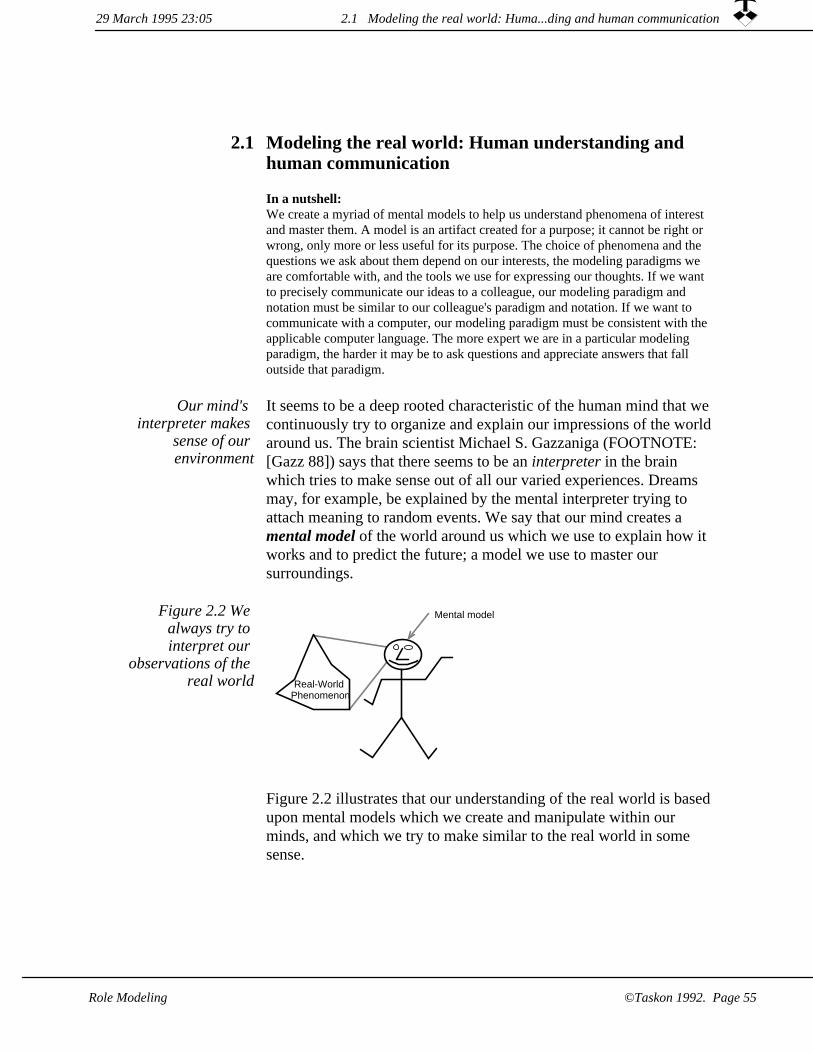
Modeling the real world: Human understanding and human communication
2.1
In a nutshell: We create a myriad of mental models to help us understand phenomena of interest and master them. A model is an artifact created for a purpose; it cannot be right or wrong, only more or less useful for its purpose. The choice of phenomena and the questions we ask about them depend on our interests, the modeling paradigms we are comfortable with, and the tools we use for expressing our thoughts. If we want to precisely communicate our ideas to a colleague, our modeling paradigm and notation must be similar to our colleague's paradigm and notation. If we want to communicate with a computer, our modeling paradigm must be consistent with the applicable computer language. The more expert we are in a particular modeling paradigm, the harder it may be to ask questions and appreciate answers that fall outside that paradigm.
Our mind's interpreter makes
sense of our environment
It seems to be a deep rooted characteristic of the human mind that we continuously try to organize and explain our impressions of the world around us. The brain scientist Michael S. Gazzaniga (FOOTNOTE: [Gazz 88]) says that there seems to be an interpreter in the brain which tries to make sense out of all our varied experiences. Dreams may, for example, be explained by the mental interpreter trying to attach meaning to random events. We say that our mind creates a mental model of the world around us which we use to explain how it works and to predict the future; a model we use to master our surroundings.
Real-WorldPhenomenon
Mental modelFigure 2.2 We always try to interpret our
observations of the real world
Figure 2.2 illustrates that our understanding of the real world is based upon mental models which we create and manipulate within our minds, and which we try to make similar to the real world in some sense.
29 March 1995 23:05 2.1 Modeling the real world: Huma...ding and human communication
Role Modeling ©Taskon 1992. Page 55

Our mental models reflect our viewpoints
As an example, consider an industrial enterprise. An accountant may model the enterprise in terms of budgets and accounts, credits and debits, expenses and revenues. A production engineer may model the enterprise in terms of the flow of materials, the machining of parts, and the assembly of products. Another production engineer may model the enterprise in terms of production processes, activities and resources, events and deadlines. An organization consultant may thinkin terms of actors and chains of command, of responsibility and authority. A computer professional may model the enterprise in terms of information (its structure, its sources and sinks), and the computer-based systems used to store and process the information.
This leads to some general observations about models:
A model is created for a purpose. My car has four wheels if I am interested in the effect of the brakes under normal circumstances. My car has two wheels if I am interested in normal acceleration, because there are only two driving wheels on my car. My car has only one driving wheel if the other one is spinning on an icy road.My car has five wheels if I am interested in maintaining correct tire pressure since I may get into deep trouble some day if I forgetto check the spare. And finally, a particular model of Citroën cars can lift a punctured wheel and continue running on the three remaining ones; a three-wheel model would be appropriate to study its behavior. So we cannot say that a model is correct per se,only that it is more or less suited for the study of specific phenomena.
1.
A model is never complete. We create models to simplify and generalize. For this purpose we ignore more than we include. The rims of my wheels are made by welding together a number of steel parts; they are painted with several coats of different paints; they are manufactured in a complex production process -- but I donot care about any of these details.
2.
We tend to think in hierarchical models, even though the world is rarely hierarchical. A house consists of a roof and four walls. Thewalls are made of bricks. But the hierarchy breaks down at the corners, where a brick belongs to two walls. Hierarchies are useful artifacts to help our thoughts. They are not inherent properties of nature, but artifacts of the models that must be applied with due caution and respect.
3.
29 March 1995 23:052.1 Modeling the real world: Huma...ding and human communication
Role Modeling©Taskon 1992. Page 56
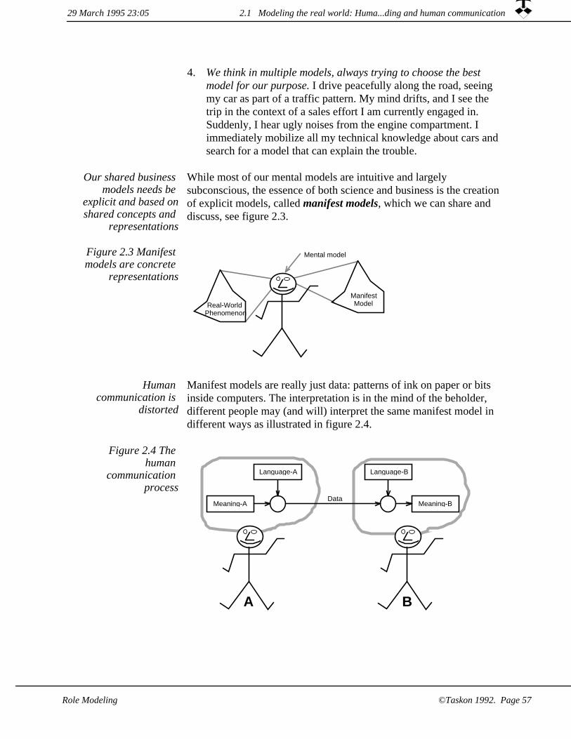
We think in multiple models, always trying to choose the best model for our purpose. I drive peacefully along the road, seeing my car as part of a traffic pattern. My mind drifts, and I see the trip in the context of a sales effort I am currently engaged in. Suddenly, I hear ugly noises from the engine compartment. I immediately mobilize all my technical knowledge about cars and search for a model that can explain the trouble.
4.
While most of our mental models are intuitive and largely subconscious, the essence of both science and business is the creation of explicit models, called manifest models, which we can share and discuss, see figure 2.3.
Our shared business models needs be
explicit and based onshared concepts and
representations
Real-WorldPhenomenon
Mental model
ManifestModel
Figure 2.3 Manifest models are concrete
representations
Human communication is
distorted
Manifest models are really just data: patterns of ink on paper or bits inside computers. The interpretation is in the mind of the beholder, different people may (and will) interpret the same manifest model in different ways as illustrated in figure 2.4.
DataMeaning-B
Language-BLanguage-A
Meaning-A
A B
Figure 2.4 The human
communication process
29 March 1995 23:05 2.1 Modeling the real world: Huma...ding and human communication
Role Modeling ©Taskon 1992. Page 57

Figure 2.4 shows the process when person A wants to communicate Meaning-A and codifies it according to Language-A, his personal vocabulary, to create the data. Person B senses these data and decodesthem according to her personal vocabulary, Language-B, to get the underlying information, Meaning-B. Since Language-A is more or less different from Language-B, Meaning-B will be more or less different from Meaning-A.
The figure illustrates the distortion that is inherent in all human communication. The process is not improved where the data are transformed and communicated through time and space via a computer system, since many of the interpersonal adjustments developed over the millennia are lost with the removal of any personalcontact between A and B as illustrated in figure 2.5.
Computer systemfilters,
transforms,stores,
and movesdata
Meaning-B
Language-BLanguage-A
Meaning-A
A B
Figure 2.5 Human communication
through a computer system
The paradigms, concepts and notation for a manifest model must be shared by the participants to make communication and discussion possible. The paradigms are usually implicit in a community of experts, which make communication fast and efficient. The paradigmsare often subconscious. Conflicting models are rarely detected and canlead to endless discussions -- such as, is analysis everything precedingdesign, or is it the study of the current situation? Every competent systems analyst knows an answer, but different analysts give different answers depending on their orientation.
Shared models essential for
communication
BOXIn our context of system modeling, precise communication of model information presupposes that all the communicants have a common description language. The OOram method has precisely defined concepts and notation. We suggest that you endeavor to learn and use them as consistently as possible, and that you complain bitterly to the authors if you find any inconsistencies or other imperfections.
29 March 1995 23:052.1 Modeling the real world: Huma...ding and human communication
Role Modeling©Taskon 1992. Page 58

Effective communication demands that the languages of the communicants are similar, and that all organizations invest in training and documentation. But as training is also a communication process, we can never achieve perfect match between individual interpretationsof the same data.
Any effective modeling paradigm is a good paradigm
Experts love to discuss whether a certain modeling paradigm is better than another one. Since being an expert means that one has internalized certain ways of thinking, these discussions frequently take the form of religious wars. My view is that it is impossible to evaluate an answer without considering the question, so that a modeling paradigm has to be evaluated on the basis of its effectiveness in a certain context. The best paradigm is the paradigm which can best helps me reach my goals. If my goals change, I must be willing to reconsider my choice of paradigms.
2.1 Modeling the real world: Huma...ding and human communication29 March 1995 23:05
Role Modeling ©Taskon 1992. Page 59

2.2 Modeling with objects
In a nutshell:The object has three properties which makes it a simple, yet powerful model building block. It has state, so that it can model memory. It has behavior, so that it can model dynamic processes. And it is encapsulated, so that and object can hide complexity.
Object orientation as a programming paradigm originated in the Simula language which was developed by the group lead by Kristen Nygaard and Ole Johan Dahl at the Norwegian Computing Center in the sixties [Birth 73]. The widespread use of object orientation in mainstream computing is due to the success of the Smalltalk languageand programming environment developed by Alan Kay and the Learning Research Group at the Xerox Palo Alto Research Center in the seventies [Gold 83].
Object oriented programming
invented in Norway in the sixties
Object Orientation isa powerful paradigm
Object orientation is but one of the many possible paradigms that can be used as a basis for thinking about systems. It is currently receiving a great deal of attention, because it seems to be useful in many different situations and for many different purposes. It has been used successfully to model human systems, such as business organizations; technical systems, such as aircraft control systems; and many differentkinds of computer-based systems.
One of the reasons for the popularity of object orientation may be that it merges many earlier paradigms such as the information models usedby database designers, the behavior models dear to the hearts of communications engineers, the functional decomposition models usedby many computer programmers, and the process models used in the analysis of organizations and integrated computer systems. We will later see that with object orientation, it is possible to express the information contained in all these different models within a single, seamless description. (But object orientation does not replace continuous models such as differential equations).
The following definitions of object orientation are derived from [Hol 77] and [HallFagan]:
29 March 1995 23:052.2 Modeling with objects
Role Modeling©Taskon 1992. Page 60

A system is a part of the real world which we choose to regard as a whole, separated from the rest of the world during some period of consideration; a whole that we choose to consider as containing a collection of objects, each object characterized by a selected set of associated attributes and by actions which may involve itself and other objects.
System and object
The operative word here is choose. We choose to regard a phenomenon as a structure of distinct objects; we choose the objects; we choose their characteristics. This choice may be "natural" if the phenomenon is discrete in nature: An organization is composed of people, and road traffic is made up of moving cars. In other cases the choice of objects may be artificial: We think of a plant as being made up of root, stem, leaves and flowers, even though there is no such distinction in nature, and it is hard to define exactly where one object ends and another begins. A corner brick could belong to either of the adjacent walls. Such difficulties should not worry us unduly, but only remind us to create precise definitions. A good model helps us understand a phenomenon of interest; a bad one does not help us and could mislead us.
Open systems are systems that interact with their environment: For a given system, the environment is the set of all objects outside the system whose actions affect the system and also those objects outside the system whose attributes are changed by the actions of the system.
Open systems have environment
ManifestModelReal World
Mental modelEnvironment Model environment
System
System model
Figure 2.6 Object-oriented models
In figure 2.6, the system is bounded by a heavy line; real world parts are shown as squares, objects are shown as rectangles; and an environment object is shown with gray outline.
The definition of open systems naturally leads to the question of whenan object belongs to the system and when it belongs to the environment -- for if an object interacts with the system as described,
2.2 Modeling with objects29 March 1995 23:05
Role Modeling ©Taskon 1992. Page 61

why not regard it as a part of the system? Following this train of thought would be inconvenient, because we would have to regard the entire universe when studying any single phenomenon. In practice, wecreate a boundary around the phenomenon under study. The system objects proper are inside the boundary, while the environment objects are outside it. The system objects are fully described in the context of the phenomenon of interest, while the environment objects are only partially described.
Many different definitions of object
orientation in use
Although the general properties of object orientation are shared by all practitioners, there are differences in the details. The differences usually boil down to differences in the semantics of the language usedto express the model. Our view of object orientation is influenced by the semantics of the Smalltalk language in which everything of interest is expressed in the terms of objects. Our view is also consistent with the definitions given by the Object Management Group [CORBA 91], an organization dedicated to the widespread application of object orientation in government and industry.
An object is encapsulated
An object itself is initially thought of as a black box with an inside and an outside as shown in figure 2.7. Looking inside, we would see that the object is capable of doing things and of storing information; itcontains methods (procedures) and data. But the object cannot do anything by itself, and there is no way that we from its outside can deduce its internal construction. This is called encapsulation. (Some authors distinguish between encapsulation and information hiding, we do not need this distinction and regard the two terms as being synonymous).
Figure 2.7 A simple object by itself
cannot do anything
An object has an identity that it keeps throughout its life time; and there will never be another object with just that identity anywhere in the world.
An object has identity
An object can have object attributes that represent information associated with it. We choose the object attributes which we consider relevant in our context.
An object can have attributes
29 March 1995 23:052.2 Modeling with objects
©Taskon 1992. Page 62 Role Modeling

Objects interact through messages
An object interacts with other objects by sending and receiving messages as illustrated in figure 2.8. Messages do not arise by magic; every message has both a sender and a receiver.
messages
Figure 2.8 Objects interact by sending messages along the paths between them
The external characteristics of an object are described completely by its identity, themessages it understands, the messages it sends to each of its collaborators, and its apparent attributes.
A message is intention-revealing. It tells the receiving object to achieve something without telling it how to do so. The message functionality is composed of three parts:
A message is a trigger that causes the receiving object to select one of its methods and execute it. The resulting action may include changes in object attributes; sending messages to one or more of the object's collaborators; and the creation of new objects.
1.
A message may be a forward data carrier that provides the receiver with some new information. The data are described in themessage parameters that may be references to other objects.
2.
3. After having processed a message, the receiver of a message may return resulting data to the sender.
Messages sent spontaneously from environment objects
A message received by an object triggers a method, and parts of this method may be to send further messages. The avalanche of messages flowing through the objects must start somewhere. Some objects will spontaneously send a message without first having received one. We call the initial message a stimulus message and the resulting sequenceof actions is called an activity. The object that sends a stimulus message must clearly be in the system environment.
The message-passing process may be recorded by an observer in the inter-object space. This observer may also deduce some apparent properties of the objects:
Object models can beobserved from inter-
object space
29 March 1995 23:05 2.2 Modeling with objects
Role Modeling ©Taskon 1992. Page 63

collaborators and message sequences. The actions performed by the object when receiving a message are defined in its method forthat message. The method itself is invisible from outside the object, but it is possible to observe any messages the object sends to other objects, so the observer can deduce the object collaboration structure. The observer can also deduce the characteristics of the message-passing process and the identity of the stimulus messages.
1.
2. object attributes. An object has state, which means that it has memory. The effect noticed by the outer observer is that the object may react differently when sent the same message at different times.
A structure of objectsis similar to a work
organization
We find it profitable to think of a pattern of collaborating objects as an organization of clerks collaborating in performing some common task. This way of thinking about systems is very similar to how Max Weber, 100 years ago, described 'rational' work organizations. Weber's ideal was to populate an organization with specialists who divided the total work load among them, who had clearly defined rights and responsibilities, and who performed their work strictly according to precisely defined rules.
No human organizations have been perfectly rational in the Weber sense. But if Weber had been alive today, he could have observed the perfect, rational bureaucracy as a set of collaborating objects inside a computer! An object may be considered as a clerk having an in-basketand an out-basket. A book of rules specify precisely the methods, or procedures to be followed by the clerk, for every message that the clerk understands. When each clerk has his own book of rules, different clerks may handle the same messages according to different rules. This is called polymorphism. Finally, the clerk will have a file of folders representing the current values of the attributes for which the clerk is responsible.
BOX: Is the postindustrial society an object-oriented society?As an aside, we may suggest that this indicates why some large, bureaucratic organizations seem to be getting into trouble in our postindustrial society. The bureaucratic organization is tuned to let people behave in a precisely prescribed and predictable manner, but computers perform this kind of behavior much better than people. The object paradigm is pervasive. We not only find it in programming and conceptual modeling, but even in the organization of the postindustrial society.
The successful postindustrial enterprise seems to be organized as a structure of autonomous units collaborating towards a common goal. In contrast to the bureaucratic model, this market model for organizations is harder to manage and
2.2 Modeling with objects 29 March 1995 23:05
©Taskon 1992. Page 64 Role Modeling

harder to populate. Individual creativity, responsibility, understanding and independence of thought are harnessed to the common good. All behavior that can be formally described is pushed down into a computerbased support system.
You can observe the contrast by comparing the large department store with the shopping mall, the large integrated factory with the network of cooperating smaller companies. The depth and importance of this transition was brought home to me when I was giving a seminar in object-oriented programming. During a recess, a man came up to me showing all signs of being deeply moved. He told me that he had been an ardent communist for more than fifty years. Gorbachov's revelations and the demise of the Soviet empire had been hard to swallow, and he was now learning that even computer programs were moving from the centralized model withall power and wisdom emanating from a main program to a decentralized model of cooperating objects.
Analysis and design Most life cycle models distinguish between analysis of an existing organization along with its problems; the specification and design of asystem that shall solve these problems; and the implementation of the new system. Different modeling paradigms have often been used for the different stages; and there has been no guarantee that information gathered in one stage has been faithfully carried over to the next stage.
We shall see that the object-oriented approach is equally applicable toall stages of the life cycle and to all levels of abstraction. We create object models of an existing organization or system, object models of a proposed future organization or system, object models of an application program, and object models of reusable program libraries. In all cases, we use the term analysis to denote the modeling of a phenomenon as a structure of interdependent object parts. This is in conformance with the common definition of the term: analysis 1: separation of a whole into its component parts 2a: an examination of a complex, its elements and their relations 2b: a statement of such an analysis ... [Webster 77]. (We also support the opposite operation, anduse the term synthesis to denote the composition of derived models from simpler ones).
There is still a distinction between the study of an existing phenomenon and the creation of a new artifact. This distinction is not in the concepts and notation we use to describe the models, but rather in the work processes we follow to create them. The study of an existing phenomenon is a reverse engineering operation, while the creation of a new system is a forward engineering operation.
We frequently find it convenient to combine the two modes of operation, because we frequently want to create new systems that have to fit into an existing environment.
We create new systems that fit
existing environments
29 March 1995 23:05 2.2 Modeling with objects
©Taskon 1992. Page 65Role Modeling

As an example, suppose we wish to create a model of an enterprise from the perspective of its formal organization. We have chosen this example domain to illustrate that objects have a wide application area;and to avoid all the technical details of computing which could easily obscure the inherent simplicity and common sense of object-oriented modeling.
A company organization
example
We defined a system as a part of the real world that we choose to consider as containing a collection of objects... We want to study how people interact to handle a travel expense account, so we choose our system to be the enterprise and choose the objects to be its people because the actors involved in this procedure are people. We elect to ignore such concepts ad departments and groups, since departments and groups are mere abstractions which do not actually do anything. Itseems natural to represent each person as an object as shown in figure 2.9.
Peter(Technical author)
Bill(Dispatcher)
Joyce(Sales clerk)
Douglas(Marketing manager)
Kim(Methodologist)
Elsie(Programmer)
Eve(Software Manager)
Bill(Bookkeeper)
Joe(Paymaster)
Adam(Chief Accountant)
Ruth(President)
John(Cashier)
Ann(Consultant)
Figure 2.9 We choose think of the
company organization as an
object model
Figure 2.9 could of course be interpreted as the conventional organization chart, decomposing the business along lines of authority and responsibility. But we choose to interpret it differently: The rectangles in this figure denote objects; the lines denote a particular set of relations between the objects. In this model, every rectangle represents a person object and every line represents a works for - reports to relation. In a more general model, objects could represent different kinds of entities and there could be different kinds of relations between them.
2.2 Modeling with objects 29 March 1995 23:05
©Taskon 1992. Page 66 Role Modeling

The object identity property is evident in our example. A person can be one of a pair of identical twins, he may change his name, amputate arms and legs, install a new heart, have a face lift, even change his sex-- the identity of the person remains the same. All the atoms of a person's body are replaced several times during his lifetime, thoughts and feelings change; and yet -- the person is the same; there has never been and will never be another person with the same identity. In our example, there are two persons named Bill. They are modeled as different objects, so we know there are two employees with the same name.
Object identity
Object attributes We could choose to consider the following person object attributes: name, job position, address, telephone number, salary, age, and competence. The attributes can be simple, such as name; or complex, such as competence.
Due to the object encapsulation property, we cannot know which forman attribute takes within the object. The age attribute could be explicitly stored in an instance variable within the object, or it could be computed whenever it was needed from an instance variable containing the birth date and a generally available current date.
As an example of message interaction, let us describe what happens when Peter wants to travel somewhere at the expense of his company.A possible process is illustrated in figure 2.10 as follows:
Message interaction
Peter sends a travelPermissionRequest-message to Eve, his manager.
1.
Eve checks her budget and her plans, and sends a travelPermission-message to Peter.
2.
3. Peter purchases the necessary tickets, travels, prepares an expensereport and sends an expenseReport-message to Eve.
Eve checks the expense report, adds her authorization, and sends an authorizedExpenseReport-message to Bill, the bookkeeper.
4.
Bill updates his accounts and sends a paymentRequest-message toJoe, the Paymaster.
5.
Joe notes the request and initiates payment to Peter.6.
2.2 Modeling with objects29 March 1995 23:05
Role Modeling ©Taskon 1992. Page 67

Figure 2.10 Messages arising from the expense
report process
Peter(Technical author)
Bill(Dispatcher)
Joyce(Sales clerk)
Douglas(Marketing manager)
Kim(Methodologist)
Eve(Software Manager)
Bill(Bookkeeper)
Joe(Paymaster)
Adam(Chief Accountant)
Ruth(President)
John(Cashier)
Ann(Consultant)
1: travelPermissionRequest2: travelPermission
3: expenseReport
5: paymentRequest4: authorizedExpenseReport
2.2 Modeling with objects 29 March 1995 23:05
Role Modeling©Taskon 1992. Page 68
Modeling with roles2.3
In a nutshell:The role model is an abstraction on the object model where we recognize a pattern of objects and describe it as a corresponding pattern of roles.
The role model supports separation of concern and describes the static and dynamic properties of a phenomenon in a single, coherent model.
Object models, as described in the previous sections, provide powerful constructs for describing a wide range of interesting phenomena. Even though we have given only outline descriptions of very simple examples, we hope you appreciate that we could have chosen more complex phenomena and augmented the models with additional information.
We need abstractions
Real cases are rarely simple. A real organization could consist of a hundred employees, and we would probably want to study dozens of different procedures. The object model would then be too complex to be studied as a whole; and we would need additional abstractions to highlight interesting aspects to enable us to think about them in a meaningful way.
One popular abstraction of object orientation is the concept of class; defining the attributes and behavior of a set of similar objects. The inheritance relation permits a derived class to be defined as an extension and modification of a base class.
The classification abstraction is not
very helpful for understanding object
structures
Figure 2.11 indicates a possible structure of capabilities of the people that populate our example organization. Ruth, Adam, Eve and Pete aremanagers -- these roles could be played by any person having the required capabilities. Observe that the capabilities of the people populating an organization do not help us understand how the organization operates. We similarly find that understanding the objectclass structure does not help us understand how the structure of objects operates.
It is as if we want to build a new home; and the architect showed us the specifications of doors, windows, walls and sanitary fittings. It may be useful to the builder to know that he can use the same windowdesign in many places, and that all windows may share some of the same production processes, but we want to know how the house will function as a home.
2.3 Modeling with roles29 March 1995 23:05
Role Modeling ©Taskon 1992. Page 69

Technical Writer
System Analyst
Programmer
Lawyer
Computer Scientist
Economist
Person
Figure 2.11 A specialization - generalization
hierarchy of the ExpenseAccount
objects
Object-oriented programming languages focus on the class, which describes isolated objects. We feel that while this may be reasonable for the programming phase of system development, it does not reflect the way we want to think about objects. We want to model structures of objects that interact in order to achieve some purpose. A class will describe the method its instances will use to service an incoming message. It does not tell us if the sender of the message uses the service correctly, nor does it tell us what happens to the messages that are sent from its instances. We want to understand the activity as a whole, but all we see is a short time slice taken out of its context.
We need to see objects in context
A role focuses on position and
responsibility of object
The notion of a class focuses on the capabilities of the objects; while the notion of a role focuses on the position and responsibility of an object within the overall structure of objects. Training people is costlyand time consuming, and we strive to give people general training which makes them capable of filling a variety of positions. Programming is also costly and time consuming, and we strive to program objects that can serve in different positions in a variety of object structures.
In role modeling we always consider
objects in context
We want an architect's plan and leave it to the builder to exploit component commonality. Later on, we shall see that the powerful notion of specialization is retained in the form of specializing patterns of interacting roles through a process called synthesis. Right now we will study individual role models and see how they represent phenomena of interest.
29 March 1995 23:052.3 Modeling with roles
Role Modeling©Taskon 1992. Page 70

The OOram technology focuses on how interacting roles achieve their
goal
In the OOram Role Model, we isolate interesting functions and study how they are realized in general patterns of interacting roles. Beck andCunningham are quoted as saying: "... no object is an island" [Helm 90]. A highbrow version of this is to refer to the classical Greek philosopher Plato, who described the philosopher as "a man who insists on seeing things together, who refuses to consider the parts outof their relation to the whole whose parts they are; and who is therefore the inexorable foe of crude and premature generalizations from whichever department of investigation happens at the time to be most in evidence."
The role model is the basic abstraction used in the OOram technology. A role model is a description of a structure of cooperatingobjects with their static and dynamic properties: what is the subject ofthe object interaction, the relationships between the objects, the messages that each object may send to its collaborators, and the information processes?
The role model is an object-oriented model of an object structure and represents a bounded part of the real world or of an interesting concept. It models patterns of collaborating objects as a similar structure of collaborating roles. This is illustrated in figure 2.12.
The OOram Role Model
A role model is a part of a structure of objects which we choose to regard as a whole, separated from the rest of the structure during some period of consideration. A whole that we choose to consider as a collection of roles, each role being characterized by attributes and by actions which may involve itself and other roles.
Role Model
ObjectsReal World
Role modelEnvironment
Roles
System
Figure 2.12 ManifestRole Models
Figure 2.12 illustrates how the role model describes a pattern in the system of objects. The system and the role model are bounded by heavy lines; objects are shown as rectangles; and environment objectsare shown with gray outline. Notice how role modeling is an additional abstraction step from the modeling illustrated in figure 2.6.
29 March 1995 23:05 2.3 Modeling with roles
Role Modeling ©Taskon 1992. Page 71

Role model is an object-oriented
model of an object structure
OOram Analysis is the breaking down of the whole problem area into separate areas of concern, and the description of each area in a role model showing interesting views of the phenomenon of interest. A phenomenon is described by a number of cooperating objects. Sub-phenomena are specified by their area of concern; objects describing a sub-phenomenon is organized in a pattern of objects, all objects having the same position in the pattern are represented by a role, we say they play the same role in the object structure. A role has identity and is encapsulated; and it is an archetypical representative of the objects occupying the corresponding positions in the object system. We can therefore say that a role model is an object-oriented model of an object structure.
The role model is therefore an abstraction:
* We suppress irrelevant objects, representing the objects that participate in the activities only.
We suppress irrelevant aspects, representing the aspects that are relevant in the context of the activities only.
*
We suppress irrelevant details, using the object encapsulation property to hide details considered uninteresting in the context of the activities.
*
We generalize object identity, representing patterns of interacting objects performing the activities by a similar, archetypical pattern of roles performing these activities.
*
The role model is the abstraction. Any pattern of objects which enacts the roles are role model instances; the objects themselves are role instances.
2.3 Modeling with roles 29 March 1995 23:05
©Taskon 1992. Page 72 Role Modeling

Figure 2.13 An object pattern is an
instance of a role model
Traveler
Bill(Dispatcher)
Joyce(Sales clerk)
Douglas(Marketing manager)
Kim(Methodologist)
Authorizer
Bookkeeper
Paymaster
Adam(Chief Accountant)
Ruth(President)
John(Cashier)
Ann(Consultant)
Elsie(Programmer)
Important roles in our travel expense example could be Traveler, Authorizer, Bookkeeper and Paymaster as illustrated in figure 2.13. A role model describes these roles, their responsibilities and rights, theirstatic relationships and their dynamic behavior.
Roles in Travel Expense example
pm
au tr
bo
A dashed super-ellipsedenotes an environment role.
A super-ellipse denotes a role,i.e., an object in the context ofan area of concern.
A single small circle representsthat the adjacent role knows aboutand may send messages toa single collaborator role.
A cross represents that the adjacentrole does not know about orsend messages to the collaboratorrole.
A line represents a collaborationrelationship between two roles.
A double small circle representsthat the adjacent role knows aboutand may send messages toany number of collaborator roles.
ENTTraveler
ENTAuthorizer
ENTBookkeeper
ENTPaymaster
Figure 2.14 ExampleOOram role model
Some analysts may prefer to replace the super-ellipses by common ellipses or circles because they are easier to draw without special tools.
Figure 2.14 is a role model collaboration view that shows the roles and the message communication paths. The figure says that the participants in the handling of a travel expense report are playing the roles of Traveler, Authorizer, Bookkeeper and Paymaster. The
29 March 1995 23:05 2.3 Modeling with roles
Role Modeling ©Taskon 1992. Page 73

Traveler and the Authorizer know about each other and exchange messages. The Paymaster does not know about the Bookkeeper and cannot send messages to him, similarly the Bookkeeper does not know about the Authorizer. This is true in the context of the current area of concern. Other role models might show close interaction between them.
Two roles are marked as belonging to the environment: the Traveler because it initiates a model activity by sending the first, unsolicited message, and the Paymaster because it is the final recipient of the completed expense report.
Associated with the line from the Traveler role is a port, a small circlethat represents the messages that the Traveler role may send to the Authorizer role in the context of this model. Other small circles are similarly interpreted.
Role models may be viewed in different
ways
A role model can be viewed from many different viewpoints and in many different ways, each view highlighting certain aspects and hiding others. We can study the inside of individual roles; we can study the messages passing between the roles; and we can study the system as seen from its environment. We can take a data-centered approach and study the roles, their semantic interpretation, their responsibilities, and their attributes. We can take a process-centered approach and study the message paths between the roles; the messagespermitted sent along each path; typical message sequences; and the role methods that are triggered by these messages.
It is important to note that the views are artifacts of our modeling process; we choose to view the phenomena under study in certain ways because they help clarify our ideas and communicate them to others. Our choices can be neither right nor wrong, but they may be more or less suitable for our purpose. The views are supplementary; and we select the combination that best suits our needs.
One view is the area of concern, which is a free text description of thesubject described by the model. Another view is the collaboration view of figure 2.14, it shows the roles and the message paths between them. A third view is the scenario, it shows a typical sequence of messages that flows through the model. The message flow starts with a stimulus message, that is an external event that triggers an activity inthe model. There are many other views, they will be discussed as we need them.
29 March 1995 23:052.3 Modeling with roles
©Taskon 1992. Page 74 Role Modeling

In this example, we would like to augment the static collaboration view of figure 2.14 with a dynamic view. Our example has one activity. This activity starts with the stimulus message when the Traveler asks the Authorizer for permission to travel. The activity includes all actions resulting from this stimulus; one typical example is shown in the scenario of figure 2.15 This scenario is a formal description of the message interaction given earlier:
1. Traveler sends a travelPermissionRequest-message to Authorizer.
2. Authorizer sends a travelPermission-message to Traveler.
Traveler sends an expenseReport-message to Authorizer.3.
Authorizer sends an authorizedExpenseReport-message to Bookkeeper.
4.
Bookkeeper sends a paymentRequest-message to Paymaster.5.
Figure 2.15 Travel Expense procedure --
typical message scenario
ENTTraveler
ENTAuthorizer
ENTBookkeeper
ENTPaymaster
travelPermissionRequest:
travelPermission:
expenseReport:
authorizedExpenseReport:
paymentRequest:
The scenario shows a sequence of messages as observed in the inter-object space. It does not describe the methods, i.e., how the objects handle their incoming messages. We can shift our point of observation to the inside of a role and describe the method that is triggered by an incoming message. Figure 2.16 is a method view. It shows the Traveler method that is triggered by the travelPermission-message:
1. Traveler purchases necessary tickets
Traveler travels2.
Traveler prepares an expense report and dispatches it to the Authorizer.
3.
2.3 Modeling with roles29 March 1995 23:05
©Taskon 1992. Page 75Role Modeling

Figure 2.16 The travelPermission-
methodENT
TravelerENT
Authorizer
travelPermission:()
<Traveler purchases the necessary tickets>
<Traveler travels>
<Traveler prepares an expense report> expenseReport:()
Role model analysis is a powerful extension of the object orientation paradigm because it permits us to identify different kinds of phenomena and to study them in isolation without losing the benefits of objects.
This capability to divide complex systems into any number of simpler ones enables us to describe any particular phenomenon within a huge system of objects. Role model synthesis (FOOTNOTE: See chapter 3)enables us to study the subsystem interdependencies by creating derived models.
Divide and conquer
We will give two additional role model examples. The first example models the transfer of files between two computers on the Internet. It is simple in the sense that it only involves two objects, but it illustrateshow separation of concern can materially simplify the models and highlight important aspects. The second example shows how we can use role modeling to describe how several objects play their roles in order to achieve some purpose.
An Internet example2.3.1
Divide and conquer Systems consisting of relatively few objects may often be described ina single role model, but many practical object structures will be too large and complex to be comprehended as a single model. We then identify different concerns, which are covered by the system, and analyze each of them separately. We divide the whole into manageable parts and conquer each part with an appropriate model. If the whole is simply the sum of its parts, we have also conquered the whole. If not, we may use OOram synthesis to create derived models which describe the dependencies. OOram synthesis will be the theme of chapter 3. For now, we will continue our studies of the use of isolated role models.
29 March 1995 23:052.3 Modeling with roles
©Taskon 1992. Page 76 Role Modeling

The Internet as a huge structure of
objects
We will use the Internet as an example of a large object structure. TheInternet connects several million computers. Its is typical of the distributed nature of Internet that nobody knows the exact number. Asseen from the Internet, the connected computers appear as objects: they have identity, they are encapsulated, and only interact by sendingmessages to each other.
The Internet is used for a wide variety of purposes. Some are well known and some are only known within their user community. We believe it is an early example of the information systems of the future;it is not a designed system, but has evolved as many different people have made their contributions. The whole is not known to anybody, and would exceed our mental capacity even if we had access to all relevant information. We can, however, select any activities we may be interested in; identify the objects that take part in the activities; idealize them into roles; and describe the activities to any desired detail.
Concern: The FTP As an example, let us select the wellknown network File Transfer Program, FTP. The interaction between the FTP participants is based on the Arpanet standard File Transfer Protocol, which allows the transfer of files between two remote computers. Two objects are involved as indicated in the top model of figure 2.17. The first takes the initiative and controls the activities; this object plays the Client role. The other is a provider of services; this object plays the Server role. Some objects (computers) are only able to play the Client role; other objects are only able to play the Server role; and some objects are able to play both roles. The abstraction from object to role permitsus to ignore these complications and create a "pure" model where each role has a single purpose. The role model is illustrated in figure 2.17 (a).
2.3 Modeling with roles29 March 1995 23:05
Role Modeling ©Taskon 1992. Page 77

Given the Client and Server roles, we can now study how they perform various activities. In one activity, the Client identifies itself by name and password to the Server so that the Server can establish the appropriate privileges. Another activity permits the Client to navigate in the Server's file directory hierarchy. A third activity permits the Client to specify operations on the "current file directory".
The FTP standards for these activities do not interest us here. The point is that we can describe each activity as an interaction process involving the Client and Server roles. Each activity will start with a stimulus message from the Client, and will result in a response in the form of appropriate changes in object attributes or some final termination message. A change directory stimulus message results in a change in the Server's currentDirectory attribute. A list directory stimulus message results in a termination message to the Client that contains the list.
Client-Server activities
Figure 2.17 Two independent role
models describe the FTP file transfer
service
dst src
rsp int
Source Destination
Client Server (a) FTP Client-Server model
(b) Data transfer model
The main purpose of FTP is to transfer files between the connected parties. Files may be transferred from the Client to the Server or from the Server to the Client. We combine these two cases by defining file transfer as being the transfer of a file from an object playing the Source role to an object playing the Destination role. This is illustrated in figure 2.17 (b).
We normally want to be able to transfer files in both directions; the Client and Server objects then need to be able to play both the Source and the Destination roles. We could alternatively define a system of objects that only permitted file transfer in one direction; a Client which could only play the role of Destination would be more secure than the general Client, since it would be unable to export files to other destinations.
The initiative for a file transfer is taken by the object playing the Client role, and the choice of roles actually played at any given time by that object depends on the direction of the desired transfer.
Concern: Transferring a file
29 March 1995 23:052.3 Modeling with roles
©Taskon 1992. Page 78 Role Modeling

The transfer of a file causes a fairly complex interaction between Source and Destination. The Source has to split the file into transferable chunks that have to be reassembled in correct sequence inthe Destination. The Source has to add redundant data to the chunks so that the Destination can check that the chunk has been transferred correctly. Protocols have to be established between Source and Destination to control the flow of data and to ensure retransmission ofincorrect chunks. All this can be studied in the role model independently of which objects play the roles of Client and Server; and which objects play the roles of Source and Destination.
File transfer activity fairly complex
The above example illustrates two points about role modeling. The first is that we need to see the involved objects if we want to describe how a structure of objects performs its duties. The second is that separation of concern is a powerful way of separating a complex situation into simple components. We could have created an object model with two objects: one playing the roles of Client, Source and Destination, the other playing the roles of Server, Source and Destination. This derived model would be more complex and harder to understand than the two simple models of figure 2.17, and the combination of the two essentially separate functionalities would not in any way add to the value of the model.
Separation of concern a powerful
simplifying device
An example model with four roles2.3.2
The second example we have chosen is that a company wants to buy something from a supplier. The company pays for the goods by instructing its bank to transfer the amount to the supplier's bank and to debit the supplier's account. The example is designed to illustrate that it may be convenient and even essential to study several objects together in order to give an adequate description of an activity.
Concern: The purchase of goods
Four roles The problem is simply modeled by four roles as shown in figure 2.18. The company is represented by the Company role, the supplier by the Supplier role, and the two banks by the PayerBank and the PayeeBank.
2.3 Modeling with roles29 March 1995 23:05
Role Modeling ©Taskon 1992. Page 79

The simple model of figure 2.18 suggests that four objects could be involved, each playing one of the roles. But this is only one of the possible mappings between roles and objects. The company and the supplier might use the same bank; the PayerBank and PayeeBank roles would then be played by the same object. Or the company could actually be a bank; the Company and PayerBank would then be played by the same object. Many other mappings are conceivable. The role model permits us to concentrate on the essence of the phenomenon, disregarding the mapping to actual objects.
Alternative mapping between roles and
objects
pay
pay
ban cli
cust
sup
cliSupplier
An object which desires to supply goods.
Company
An object which desires to purchase goods.
PayerBank
The bank of the Company.
PayeeBank
The bank of the Supplier.
Figure 2.18 The collaborating roles
The Scenario of figure 2.19 shows a typical message sequence for a purchasing activity.
OOram technology supports many views
Figure 2.19 A Scenario shows a
typical message sequence
Company Supplier PayerBank
PayeeBank
requestBid
bid
order
goodsAndInvoice
paymentOrder
transferOrder
debitAdvice
29 March 1995 23:052.3 Modeling with roles
©Taskon 1992. Page 80 Role Modeling

Interfaces show messages sent
A third view is shown in figure 2.20; it is a collaboration view annotated with the messages interfaces for each of the ports. The Company role can receive two messages from the Supplier role: bid and goodsAndInvoice. There are no messages sent from the Supplier role to the PayeeBank in this model. The Supplier role is therefore marked as not knowing the PayeeBank. (This is in the context of this role model only, since the Supplier object is very likely to know its bank!)
The Company role can send the messages requestBid and order to the Supplier. It can also send the message paymentOrder to the PayerBank. The PayerBank can send transactionReceipt-messages to the Company and the transferOrder-messages to the PayeeBank. Finally, the PayeeBank can send transferReceipt-messages to the PayerBank and debitAdvice-messages to the Supplier.
Notice the fine-grained control of message interaction provided by therole model. The PayerBank understands the paymentOrder message, but it can only be legally sent from an object that plays the Company role.
Figure 2.20 Interfaces specify
messages that may be sent from a role to
a collaboratorcli
ban cli
pay
paycust
sup
Company<SupplierbidgoodsAndInvoice
Company<PayerBanktransactionReceipt
Supplier<CompanyorderrequestBid
Supplier
PayeeBank<PayerBanktransferOrder
PayerBank<PayeeBanktransferReceipt
PayerBank<CompanypaymentOrder
Supplier<PayeeBankdebitAdvice
Company PayerBank
PayeeBank
2.3 Modeling with roles29 March 1995 23:05
©Taskon 1992. Page 81Role Modeling

Many views give expressive power to the analyst/designer
Combined with the separation of concern exemplified in the previous section, the appropriate selection of views gives the analyst powerful means for reducing complex problems to a number of simple descriptions.
The example also illustrates the advantages of roles having identity. We can not only check that some supplier will be paid; we can actually check that the supplier who delivered the goods is also the supplier that ultimately gets paid.
29 March 1995 23:052.3 Modeling with roles
©Taskon 1992. Page 82 Role Modeling

The model creation process and its deliverables2.4
In a nutshellWork processes have to be tailored to the task at hand and the people who are going to do the work. Further, there is no work process that magically ensures a successfulmodeling operation; quality results can only be produced by quality people. The deliverables from a work process are more concrete, and we suggest a list of deliverables that can be taken as a starting point.
Finding the objects is considered a hard problem for the novices, and fairly straight forward for the experienced analysts. We suggest a few hints to help finding the objects, but suggest that the most important source is to be found in reusable components. Such components package accumulated expert experience and provide excellent starting points for both novices and experts.
Work processes tailored to tasks
Whenever we want to achieve something, we perform a number of operations that lead from where we are to where we want to be. The sequence of operations is a work process where the operations are seen as process steps. There is no single work process that covers all needs. We have to tailor our own process based on where we are, where we want to go, and the available technology.
OOram role model analysis is appropriate for a great variety of different work processes. Each process will apply the views that are most informative. It is unlikely that any process will ever need all of them.
It is important to note that these views are artifacts of the modeling process. We choose to view the phenomena under study in certain ways. Our choices can be neither right nor wrong, but they may be more or less suitable for our purpose.
The sequence of steps we suggest in the following are therefore to be construed more as a suggested documentation structure than as a default work process. You may want to develop your own preferred sequence of steps, taking the steps proposed here as a starting point.
The model creation process introduced in chapter 1.3 consisted of the following six steps:
1. Determine the Area of Concern. Write a free form (prose) description of the issue under consideration.
Understand the problem and identify the nature of the objects. For the given area of concern, identify the nature of the objects that will be involved.
2.
29 March 1995 23:05 2.4 The model creation process and its deliverables
Role Modeling ©Taskon 1992. Page 83

3. Determine Environment roles and Stimulus/Response. Describe the messages that are sent from environment roles and cause an activity in the described system. Also describe the response, which is the overall effect of the activity.
Identify and understand the roles. Separate and idealize the tasks and responsibilities of the objects and describe them as the roles they play in the system.
4.
Determine the message sequences. Create scenarios showing the activities performed by the roles in response to the stimulus messages.
5.
Determine the collaboration structure. Show the roles in a structure of collaborating objects.
6.
Determine Interfaces. Determine the messages that each role may send to each of its collaborators.
7.
Determine the role behavior. Describe interesting methods triggered by messages for the key roles.
8.
These steps provide you with an object-oriented model of the phenomenon under study. It provides a static description defining the roles, their characteristics and collaboration structure, and it provides a dynamic description defining the message processes.
The novice analysts frequently struggles with finding the objects or roles. This is a symptom of a deeper problem, namely that the analyst has not yet internalized the object paradigm.
There is, unfortunately, no known procedure which will always yield suitable objects or roles up front. But it may be a comfort to know thatonce you have mastered the object paradigm, your intuition will usually provide a good initial choice. In a contribution to the Internet, Ward Cunningham suggests that most objects in any big system are obvious and easily found by examining the vocabulary of anyone familiar with the domain. Most remaining objects can be found by pooling the wisdom and experience of interested parties. A possible technique is to use the CRC cards as described below. Finally according to Cunningham, there are a few objects that can only be found by living and working with the system over an extended period of time. These few objects are often crucial and make accumulated complexity melt away.
Finding the objects
2.4 The model creation process and its deliverables 29 March 1995 23:05
Role Modeling©Taskon 1992. Page 84

It is thus easy to find most of the objects up front, but there is really only one way to find all of them: study a similar system that has had the benefit of a long history of evolution and improvements. This is one of the most compelling reasons for applying reusable patterns andframeworks; they provide mature solutions to known problems.
Below, we endeavor to give a few general hints to help the novice find the initial objects.
Objects found by combination of
personal creativity and study of existing
systems
What is a good object?
A good object has a clearly defined role in the overall structure ofobjects. (An object cannot be good per se, only in the context of the purpose and structure of the role model!)
1.
2. A good structure of objects represents the area of concern described by the model in an intuitively pleasing manner
Where to look for objects:
1. Study the problem domain
¤ Consider general domain aspectsConsider users' expressed needs¤
¤ Consider any other available source
2. Study available text
Nouns are candidates¤
Study available drawings and overview diagrams3.
¤ Entities are candidates
What is often a good object?
1. A model of a part of the real world.
A thing to which thought or action is directed.2.
3. Something which would be described as an entity in an entity-relation model.
4. Something which has identity and exists over time.
What is often not an object?
A value. A value is something without interesting internal structure or behavior in the context of the role model. A value may then be represented as a role attribute
1.
29 March 1995 23:05 2.4 The model creation process and its deliverables
Role Modeling ©Taskon 1992. Page 85

2. A process. If the process can be adequately represented as a sequence of messages flowing in the model, it is modeled as role model activity and described by an appropriate dynamic view such as a Scenario or a state diagram.
3. Time. Time is usually implicit in the model. (But a Timer is concrete and may be a good object.)
A good technique for finding objects and roles is to use Class-Responsibility-Collaborator cards (CRC-cards) as the focus points of group discussions. The CRC cards are adapted from Cunningham and Beck. See for example [Wirfs-Brock 90].
CRC cards support working in groups
The CRC cards are index cards, each card is divided into three areas as shown in figure 2.21. One card is created for each role, and the group discusses how the roles interact to achieve the response specified for each stimulus. Individual group members should claim ownership of one or more roles (cards). This makes it much simpler tocheck that each role has the necessary information to take responsibility for its own part of the activities:
1. CRC cards support the decomposition part of the design and help assign responsibility to the constituent roles.
2. Objects collaborate through intention-revealing message sends.
An attractive characteristic of index cards is that they are concrete: they can be owned, pointed at and moved about.
3.
The technique gives the group the impression (illusion) of "completeness" when they are done.
4.
Name:
Responsibility:
Collaborators:
Authorizer
Responsible forrelevance of tripand for availablebudget
TravelerBookkeeper
Figure 2.21 CRC example card for the
Authorizer role.
Notice that when a group works with CRC cards, they study the roles and the messages simultaneously. The technique therefore tends to be effective both for finding "good roles", and for finding simple, but
29 March 1995 23:052.4 The model creation process and its deliverables
©Taskon 1992. Page 86 Role Modeling

adequate, model behavior by enacting the Scenarios (even if the dynamics of messages passing is not recorded on the cards). The CRCtechnique supports role modeling directly, since both focus on object responsibility and object interaction.
A structure of roles is similar to a work
organization.
The creation of a structure of collaborating roles is, in many ways, similar to creating an organization of people collaborating in performing some common task.
We have earlier mentioned Max Weber's dream of a rational work organization. The following literal excerpts from [Etzioni 64] form a beautiful description of this "perfect bureaucracy": logical, rational, extremely efficient, and extremely rigid. Applied to the computer system, it is perfect. Applied to the human organization, it can become a nightmare (my comments in parenthesis):
Max Weber's 'rational' work
organization was object-oriented
Emphasis of structure. "A continuous organization of official functions bound by rules." Rational organization is the antithesisof ad hoc, temporary, unstable relations; hence the stress on continuity. Rules save effort by obviating the need for deriving a new solution for every problem and case; they facilitate standardization and equality in the treatment of many cases. (In the travel expense case, we focus on the actors and their formal responsibilities. We ignore all informal contacts and interactions.)
1.
2. A specific sphere of competence. "This involves (a) a sphere of obligations to perform functions which have been marked off as part of a systematic division of labor; (b) the provision of the incumbent with the necessary authority to carry out these functions; and (c) that the necessary means of compulsion are clearly defined and their use is subject to definite conditions." Thus a systematic division of labor, rights and power is essential for rational organization. Not only must each participant know his job and have the means to carry it out, which includes first of all the ability to command others, but he also must know the limits of his job, rights, and power so as not to overstep the boundaries between his role and those of others and thus undermine the whole structure. (In the travel expense case, we focus on the formal object attributes and actions. We ignore all "soft" aspects such as the personal characteristics, motivations, benefits and social aspects.)
29 March 1995 23:05 2.4 The model creation process and its deliverables
Role Modeling ©Taskon 1992. Page 87

Hierarchy. "The organization of offices follows the principle of hierarchy; that is, each lower office is under the control and supervision of a higher one." In this way, no office is left uncontrolled. Compliance cannot be left to chance; it has to be systematically checked and reinforced. (Well, we are not quite so rigid, but we carefully control the collaborators of an object and the messages it may send to them.)
3.
Norms of conduct. "The rules which regulate the conduct of an office may be technical rules or norms. In both cases, if their application is to be fully rational, specialized training is necessary. It is thus normally true that only a person who has demonstrated an adequate technical training is qualified to be a member of the administrative staff...." (This is strictly true, the system is completely defined by the program.)
4.
Independence. In order to enhance the organizational freedom, the resources of the organization have to be free of any outside control and the positions cannot be monopolized by any incumbent. They have to be free to be allocated and re-allocated according to the needs of the organization. "A complete absence of appropriation of his official positions by the incumbent" is required. (This is the principle of object encapsulation. An object should only influence other objects through their official interfaces.)
5.
Documentation. "Administrative acts, decisions, and rules are formulated and recorded in writing...." Most observers might view this requirement as less essential or basic to rational organization than the preceding ones, and many will point to the irrationality of keeping excessive records, files, and the like, oftenreferred to as `red tape'. Weber, however, stressed the need to maintain a systematic interpretation of norms and enforcement of rules, which cannot be maintained through oral communication. (A trivial fulfillment of this rule is through the program source code. We read the rule to mean that we also want higher level documentation describing goals, specifications, architecture and design.)
6.
Weber's rules for a 'rational' organization and Etzioni's comments are almost uncannily appropriate for the design of object-oriented systems. Admittedly, we cannot construct a complete system as a rigidhierarchy of objects. But if we consider individual activities, each of these activities can be designed as a distinct role model according to rules which are very similar to the rules formulated by Weber.
29 March 1995 23:052.4 The model creation process and its deliverables
Role Modeling©Taskon 1992. Page 88
We propose the following OOram rules for rational object-oriented design:
Emphasis on structure. The relations between participating roles in a rational design of a role model are bound by a specification that is part of the design, not just the implementation.
1.
A specific sphere of competence. For each role, this involves (a) the duty to react appropriately to messages received, which have been marked off as part of the systematic division of responsibility; (b) the right to delegate work to collaborators by sending certain messages to them at certain times as clearly described in the design, and the duty not to send any other messages.
2.
3. Hierarchy. In every role model, a role is under the control and supervision of a higher one. In this way, no role is left uncontrolled. Specifically, this means creating the role, initializing it, connecting it with its collaborators in the overall structure, and removing it at the appropriate time. (This is the weakest rule and not always relevant.)
Norms of conduct. For a given role model, the behavior of a role is regulated by rules or norms. By rules, we mean precise statements about the behavior. By norms, we mean general guidelines. The distinction relates to the responsibilities of the designer versus the implementor. Rules put more constraints on the implementor than do norms.
4.
5. Independence. An object may play a role in several role models. The collaborators of an object in the context of one role model donot know about its other roles, and thus cannot infringe on its behavior in the other contexts.
Documentation. Each role model must be fully documented on the design level. It is particularly tempting to let the norms of conduct for a role model be an informal part of the programming team's culture -- "the way we do it here". This is guaranteed to eventually cause you trouble. Most real systems are so complex that we can only trust their correctness if they are constructed from well-documented models, each of which "is so simple that itis obviously correct."
6.
7. Reusability. While this rule has no counterpart in Weber's rules, itcertainly has its counterpart in real organizations. We continuously search for generally useful role models, and we reuse an existing role model whenever appropriate. In some cases,we can also reuse the code; in other cases, just the pattern. Either way, reuse improves system reliability and reduces the work involved in understanding programs developed by other people.
2.4 The model creation process and its deliverables29 March 1995 23:05
©Taskon 1992. Page 89Role Modeling

2.5 Basic OOram role modeling concepts and notation
In a nutshellOOram role model analysis helps the developer master object structures of any size. The object structure may exist. The purpose is then to understand it. Alternatively, the purpose may be to design a new object structure. The objects are then imaginary.In both cases, the OOram approach is to identify different concerns which are represented in the object structure and to create idealized object models, called role models, which focus on the selected area of concern and ignores everything else.
The essence of role modeling is that we always consider objects in context. An isolated object cannot do anything because a message must have both a sender and areceiver. It is only when we consider structures of collaborating objects that we can study cause and effect; and that we can reason about the suitability and correctness of the objects and their structure.
2.5.1 The Object
We have defined objects as being encapsulated. This is illustrated in figure 2.22. It means that we can observe some of its properties when we observe it from outside the object; while other properties can only be seen from inside.
External and internalobservation
MessagesAttributes
Encapsulation hidesinside properties
MethodsInstance variablesState
Object
Figure 2.22 External and internal object
properties
2.5 Basic OOram role modeling concepts and notation 29 March 1995 23:05
©Taskon 1992. Page 90 Role Modeling

External object properties
Observed from the outside, objects appear as indivisible atoms. Each object has its own unique identity, and is characterized by its behaviorand attributes.
The behavior of the object is characterized by the messages it can receive, and also by the messages it can send to other objects. Many different message semantics have been proposed. Our selection is adopted from the Object Management Group in [CORBA 91]:
Messages
Synchronous. Only one object can be active at any time, and the sender's actions continue only after the receiver's actions are completed. The receiver may return a result to the sender.
1.
2. Synchronous deferred. The sender object must be ready to send amessage and the receiver object must be ready to receive it beforeit can be transferred. The sender and receiver objects are synchronized at the time of message transfer. The sender's actions continue after the receiver has accepted the message. A return value could confirm the receipt of the message.
3. Asynchronous. The sender can transmit a message at any time, and the sender's actions continue immediately. The receiver manages a queue of incoming messages, and may need to wait foran acceptable message to arrive in the input queue. A return valueto the sender could confirm that the message has been put into thereceiver's input queue.
An Interface is a set of messages
The number of different messages understood by an object may be very large, and we find it convenient to group them: an OOram interface is a named set of messages, or more precisely: message types. This use of the term conforms with [CORBA 91], but some professionals use the term interface to denote signals going in both directions, i.e., both messages sent and received. The OOram technology uses two interfaces to describe this: one for messages sent and another for messages received.
A role model consisting of at least two roles is needed to describe the object interaction in space and time.
2.5 Basic OOram role modeling concepts and notation29 March 1995 23:05
Role Modeling ©Taskon 1992. Page 91
An object may store information. To the outside observer, this information is described by the object's named attributes. Attributes are virtual in the sense that they do not say anything about how the object represents the information internally in the instance variables described below.
Attributes
Attributes are only visible to the outside observer through messages whose behavior depend on the current value of one or more attributes.(Usually, but not always, through a value returned from the receiving object.)
Internal object properties
As seen from the inside, the object realization is described by its methods, its instance variables and its state.
A method defines the action taken by an object when receiving a message. The method may cause the object to send messages to one ormore of its collaborator objects, it can create new objects, and it may have the side effect of causing a change to one or more of the object's instance variables.
Methods
The distinction between message and method is essential because it permits different objects to handle the same message with different methods; each object can "do the right thing" when they receive a message. This feature of object orientation is variously called polymorphism and late binding in the literature.
The fancy names are unimportant, the ability to hide the details of an operation inside an object is essential. For example, different graphical objects can respond to a display-command according to their individual characteristics; different bank account objects can compute accumulated interest according to the nature of the account; different TravelAuthorizer persons can follow different rules when they determine their response to a travel permission request.
Instance variables The instance variables represent attribute information. An instance variable may hold the value of an attribute directly, or the object may have a method that enables it to compute the value of an attribute from the values of one or more instance variables.
2.5 Basic OOram role modeling concepts and notation 29 March 1995 23:05
Role Modeling©Taskon 1992. Page 92

The distinction between attribute and instance variable is essential because it permits the analyst to think in terms of information without considering its representation. The attribute could for example be a person's age, the instance variable could hold the person's birth date so that the object could compute the age whenever needed. The objectcould even delegate the responsibility for maintaining the information to some other object; an instance variable could hold a reference to theother object and a method could know how to retrieve the required information from it. This possibility will be discussed in depth in section 3.2.1: Aggregation: Linking models on different levels of abstraction.
The internal conditions of an object which affect the object's behaviorare abstracted into the object's possible states, where a state determines which messages the object is ready to receive and how it will process them. When the object receives a message, it performs anaction depending on the current state, and enters a next state which may be different from the current state.
State
If the actions taken when the object receives a message are different in different states, the corresponding method will be a composite withdifferent action branches for the different states.
Some practitioners use the terms instance variable and state interchangeably. We find it useful to distinguish between these two terms in order to cater to the relatively few situations where it is necessary to study objects with state dependent behavior. More detailsin section 6.3: State Diagram view.
The Role Model2.5.2
OOram analysis is defined as the description of some interesting phenomenon as a system of interacting objects. In data processing, analysis is commonly used to denote the study of what is visible to the user community, while design is used to denote the description of the internal construction of a new system. OOram analysis covers both these interpretations; we analyze the world as perceived by the user community, and we analyze the system as perceived by its creators. The antonym is synthesis, the composition of a whole from its constituent of parts.
OOram analysis
2.5 Basic OOram role modeling concepts and notation29 March 1995 23:05
©Taskon 1992. Page 93Role Modeling

The OOram role model supports separation of concern. A large and complex phenomenon, which we think of as a large and complex structure of interacting objects, may be split into a number of subphenomena. Each subphenomenon is described by its own role model.
Separation of concern
A role is an idealized object in the sense that it is an archetypical example of the object within the pattern, and that the role's characteristics is the subset of the object's characteristics that are of interest within the limited scope of the subphenomenon.
An object model is a structure of objects representing an aspect of a phenomenon. A role model is a structure of roles representing an aspect of an object model; it is an object-oriented model of an object structure. In simple cases, the role model is identical to the object model and there is exactly one role for each object.
Definitions
A role model is a part of a structure of objects that we choose to regard as a whole, separated from the rest of the structure during some period of consideration. It is a whole that we choose to consideras a collection of roles; each role being characterized by its attributes and by the messages it may receive from and send to other roles.
For a given system of roles, the environment is the set of all roles outside the system that send messages to the objects of the system, andalso those roles outside the system that receive messages from the roles of the system.
Roles have all the properties of objects: They have identity and attributes; they are encapsulated; they interact by message-passing; and their actions are defined by their methods. Inheritance is supported by a process called synthesis that will described in chapter 3: Role model synthesis.
There is a many-to-many relationship between objects and roles: an object may play several different roles from the same or different role models; and a role may be played by several different objects.
We may observe the system of interacting roles from different observation points. OOram supports three points of observation, called perspectives:
A role model may be observed in different
perspectives
29 March 1995 23:052.5 Basic OOram role modeling concepts and notation
Role Modeling©Taskon 1992. Page 94

Environment perspective, where the observer is placed in the system environment so that she can observe the system's interaction with its environment roles.
1.
External perspective, where the observer is placed between the roles so that she can observe the messages flowing between them and indirectly deduce the role attributes.
2.
Internal perspective, where the observer is placed inside a role so that she can observe its implementation.
3.
When thinking about some interesting phenomenon, the OOram analyst creates an object model of the phenomenon in her head. This model can only be captured on paper or a computer screen as one or more views -- these views are different presentations of an underlying OOram model. In the case of a paper report, the underlying model is abstract in the sense that it has no explicit representation. In the case of a computer-based system, the underlying model can be represented in an object database. See figure 2.23.
The analyst can only observe views of the
underlying model
Figure 2.23 The analyst can only see
and manipulate views of an
underlying model
OOramModel
Mental object model
view
view
Systems of interacting objects may be studied in different views, with each view expressing certain aspects of the system of roles while suppressing others. OOram analysis supports ten different views on a role model:
Ten different views on the same model
Area of Concern view, which is a textual description of the phenomenon modeled by the role model.
1.
2. Stimulus-response view, showing how environment roles may cause some activity in the system of roles by sending a stimulus message, and the overall effect of the activity, called the response.
3. Role List view, showing a list of all roles with their explanations and attributes.
4. Semantic view, showing how we attach meaning to the roles and the relationships between them.
29 March 1995 23:05 2.5 Basic OOram role modeling concepts and notation
©Taskon 1992. Page 95Role Modeling

Collaboration view, showing the pattern of roles and the message paths between them.
5.
Interface view, defining all messages that may be sent along each of the message paths.
6.
7. Scenario view, showing example time sequences of messages flowing between the roles.
8. Process view, showing how data flows between the roles and the actions taken by the roles to process the data.
9. State Diagram view. There may be one state diagram for each role. It describes the possible states of the role, the signals that areacceptable in each state, the action taken as a result of each signal,and the next state attained after the action is completed. The only kind of signal possible in our model is the receipt of a message.
Method Specification view. When an object receives a message, the message triggers the execution of a method within the object. The method specification view describes the messages to be sent from the method with the corresponding receiving roles. It may also include a more or less formal description of the procedure.
10.
The views are only meaningful in certain perspectives as shown in table 2.1. The basic views are described in the following; the views marked (*) are described in chapter 6.
Table 2.1 Applicability of the
views in the different perspectives
Environment perspective External perspective Internal perspective
Area of concern view Applicable
Stimulus-response view Applicable
Role List view (*) Applicable Applicable
Semantic view (*) Applicable
Collaboration view Applicable
Scenario view Applicable Applicable
Interface view Applicable Applicable
Process view (*) Applicable Applicable Applicable
State Diagram view (*) Applicable
Method Specification view Applicable
Important notes:
The views are different presentations of one and the same model for the purposes of documentation and user interaction.
1.
A subset of the views should be selected to suit a particular modeling process. It is unlikely that anybody will ever need them all.
2.
2.5 Basic OOram role modeling concepts and notation 29 March 1995 23:05
©Taskon 1992. Page 96 Role Modeling

The views are not orthogonal. Their mutual consistency should preferably be enforced automatically, but it is also possible to do so by manual means.
3.
Six of the views are described in the following subsections with a notation appropriate for documentation; the rest are described in chapter 6. The OOram language notation given in Appendix A is more formal. It is harder to read for a human, but more appropriate forautomatic information interchange between OOram systems.
Area of Concern view
The area of concern view (figure 2.24)is a free text describing the phenomenon modeled by the role model. The text should indicate the purpose of the model and be sufficiently precise to enable a reader to determine which phenomena are covered by the model, and which phenomena are not covered. The description must be precise because it will be used to determine which objects belong to the system and which objects are outside it.
Area of Concern view describes the
model as a whole
Figure 2.24 Area of Concern example
This role model describes how an enterprise purchases goods and pays for them.
Stimulus-response view
A stimulus is a message that triggers
an activity
Stimuli are defined as messages being sent spontaneously from an environment role to one of the system roles. The sequence of actions taken by the system is called an activity. The response is one or more messages sent from the system to one or more environment roles, or some other changes that are described as a free text such as changes toobject structure or attributes. The stimulus-response relationships are shown in a table as shown in figure 2.25; an example is shown in figure 2.26.
Figure 2.25 Graphical notation isin the form of a table
Stimulus message Response messages Comments
environment role >> message name
{environment role << message name}...
Free text descriptionof other results
29 March 1995 23:05 2.5 Basic OOram role modeling concepts and notation
©Taskon 1992. Page 97Role Modeling

Figure 2.26 Stimulus-Response
example
Stimulus message Response message Comments
Enterprise >>requestBid
Vendor << creditAdvice
The enterprise has receivedand paid for the desired goods
Alternative is to show system as
virtual role
An alternative presentation of Stimulus-Response is to use a collaboration view where all the system roles are shown as a single virtual role. The view is annotated with the stimulus and response messages.
Collaboration View
The Collaboration view shows the roles and the message paths between them. Our notation is shown in figure 2.27 and illustrated in figure 2.28.
A dashed super-ellipse denotes anenvironment role.Dashed circles and ellipses are alternatives.
A line denotes a message pathbetween collaborating roles.
A small double circle denotes a multiple port,indicating that the adjacent role knows aboutany number of collaborator roles, one ofwhich is shown in the view.
A small circle denotes a simple port,indicating that the adjacent role knows aboutexactly one collaborator.
A cross denotes that the adjacent roledoes not know the collaborator.
<role name>
Comment or explanation.<comment>
A super-ellipse denotes a system role.Circles and ellipses are alternatives.<role name>
Attribute names may be listed withinthe role symbol.
<role name>
<attributes>
Figure 2.27 Collaboration view
notation
[Martin 87] recommends that data should be represented with square-cornered rectangles, while activities should be drawn with round corners. Roles (and objects) combine data and activities. We have, therefore, searched for a shape that is neither round nor square to represent them. A super-ellipse seems to satisfy our needs. Its shape is
29 March 1995 23:052.5 Basic OOram role modeling concepts and notation
Role Modeling©Taskon 1992. Page 98

shown in the figures. (FOOTNOTE: The formula of the super-ellipse is (x/a)**4 + (y/b)**4 = 1. We recommend that you use circles or ellipses if your tools do not support super-ellipses).
Figure 2.28 Collaboration view
illustration
Enterpriseknows exactlyone PayerBank.
PayeeBank is a system role.
ban cl
cus
ven
ban cl
bnk
bnk
This port points to anynumber of collaborators,of which Enterpriseis a typical example.
Enterprise is an environmentrole because it sends astimulus message.
Vendor
SD
An object which desires to supply goods.
Enterprise PayerBank
PayeeBank
Vendor is an environment rolebecause it receives a final message.
Role explanation
Role symbols may be decorated to indicate the nature of the object. Figure 2.29 illustrates some possibilities, but the analyst is free to define her own symbols.
Role symbols may bedecorated
Figure 2.29 Examples of
decorated role symbols
A role representing a person
A role representing a service
A role representing a tool
A role representing a timer
29 March 1995 23:05 2.5 Basic OOram role modeling concepts and notation
©Taskon 1992. Page 99Role Modeling
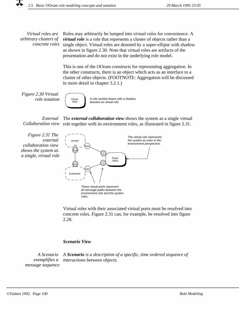
Roles may arbitrarily be lumped into virtual roles for convenience. A virtual role is a role that represents a cluster of objects rather than a single object. Virtual roles are denoted by a super-ellipse with shadowas shown in figure 2.30. Note that virtual roles are artifacts of the presentation and do not exist in the underlying role model.
This is one of the OOram constructs for representing aggregation. In the other constructs, there is an object which acts as an interface to a cluster of other objects. (FOOTNOTE: Aggregation will be discussed in more detail in chapter 3.2.1.)
Virtual roles are arbitrary clusters of
concrete roles
Figure 2.30 Virtual role notation Virtual
RoleA role symbol drawn with a shadowdenotes an virtual role
The external collaboration view shows the system as a single virtual role together with its environment roles, as illustrated in figure 2.31.
External Collaboration view
The virtual role representsthe system as seen in theenvironment perspective.
cus
ven
ban
cl
ban
cl
These virtual ports representall message paths between theenvironment role and the systemroles.
Vendor
SD
Enterprise
PayerBank
Figure 2.31 The external
collaboration view shows the system as a single, virtual role
Virtual roles with their associated virtual ports must be resolved into concrete roles. Figure 2.31 can, for example, be resolved into figure 2.28.
Scenario View
A Scenario is a description of a specific, time ordered sequence of interactions between objects.
A Scenario exemplifies a
message sequence
29 March 1995 23:052.5 Basic OOram role modeling concepts and notation
Role Modeling©Taskon 1992. Page 100

An interaction represents the event of transmitting a message from a sender object to a receiver object. Both the sending and the receiving objects must be represented as roles in the role model. Interactions are assumed to be atomic and strictly ordered in time.
The Scenario thus shows an example sequence of messages as they flow through the structure of objects. The first message must be one of the role model's stimulus messages. Scenarios may be created in the environment perspective and in the external perspective.
The OOram Scenario is adapted from the Message Sequence Chart defined in the standard [CCITT Z120] with the modifications needed to make it fit our object model. Our notation is shown in figure 2.32 and exemplified in 2.33.
In his book on object-oriented software engineering, Jacobson uses the term actors to denote a system's environment objects [Jacobson 92]. An OOram stimulus message is an operation initiated by an actor,and a use case is an OOram activity, i.e. a typical sequence of actions in the system that results from the stimulus. We propose that Scenarios are admirably suited to describe use cases. A single Scenario, as described here, will be sufficient for simple use cases, and the aggregation and synthesis operations discussed in chapter 3 enable us to dissect a use case down to any desired detail.
Figure 2.32 ScenarioNotation
Role
Synchronous deferred interaction
Asynchronous interaction
Time line, withincreasing time downwards
Interactions:
Synchronous interaction
Unspecified interaction
S
D
Actors:
Creation of receiver prior to interaction
Method return
A
C
The three different semantics of messages were defined on page 90??.
29 March 1995 23:05 2.5 Basic OOram role modeling concepts and notation
Role Modeling ©Taskon 1992. Page 101

Figure 2.33 ScenarioIllustration
Enterprise Vendor
Fsm
PayerBank
PayeeBank
requestBid
bid
order
goodsAndInvoice
paymentOrder
transferOrder
creditAdvice
The first interactionis by definition astimulus
Interaction
Time line
Message name with or without actual parameters
System roleEnvironment role
Interface view
An interface view defines a set of messages that may be sent from onerole to another. Interfaces are usually specified textually, but may alsobe shown in an annotation in the collaboration view shown in figure 2.34.
Interfaces define messages that may
be sent
A rounded rectangle denotes an interface.A dashed line associates the symbol with a port.<Interface name> is the name of an interface or a port.<Message list> is either a list of messages or a list of interface names.
<Interface name>
<Message list>
Figure 2.34 Graphical interface
notation
ban cl
ban cl
cus
ven bnk
bnk
Enterprise<VendorbidgoodsAndInvoice
Vendor<EnterprisebidRejectedorderrequestBid
An interface named 'Vendor<Enterprise'("Vendor-from-Enterprise")defines the messages that may besent to Vendor from Enterprise.
Vendor
SD
Enterprise PayerBank
PayeeBank
Figure 2.35 Graphical interface
illustration
29 March 1995 23:052.5 Basic OOram role modeling concepts and notation
Role Modeling©Taskon 1992. Page 102

We find that we can only use the graphical form of figure 2.35 in simple cases such as in very high-level overviews, trade show demonstrations and tutorials. Real world models are simply too complex for the graphical presentation to fit on a computer screen or asheet of paper, and we prefer a textual form. As with the role list view, the textual form of the interface view may be written informallyor in the formal OOram language. The full language syntax is discussed in appendix A, we give a simple example of the formal textual notation in figure 2.36 and an informal form in figure 2.37.
Textual form more useful
A comment is associated with every message definition. Use it to describe the functionality of each message as clearly as possible. Focus on the intent of the message without saying how the receiver is to perform the operation. Try to keep the interfaces lean and powerful.Look out for nearly identical messages and try to merge them.
Figure 2.36 Textual specification of
interfaces in the OOram language
interface 'Vendor<Enterprise' message synch 'requestBid'
explanation "Request bid for delivery of specified goods."message synch 'order'
explanation "Order goods"message synch 'bidRejected'
explanation "Reject bid"interface 'Enterprise<Vendor'
message synch 'bid' explanation "Submitting bid"
message synch 'goodsAndInvoice' explanation "Sending goods together with invoice"
interface 'PayerBank<Enterprise' message synch 'paymentOrder'
explanation "Order to transfer money"interface 'Enterprise<PayerBank'
message synch 'transactionReceipt' explanation "Acknowledging order to transfer money"
interface 'PayeeBank<PayerBank' message synch 'transferOrder'
explanation "Order to transfer money"interface 'PayerBank<PayeeBank'
message synch 'transferReceipt' explanation "Acknowledging order to transfer money"
interface 'Vendor<PayeeBank' message synch 'creditAdvice'
explanation "Advising that money has been received on behalf of vendor"
29 March 1995 23:05 2.5 Basic OOram role modeling concepts and notation
Role Modeling ©Taskon 1992. Page 103

Figure 2.37 Informaltextual specification
of interfaces
interface 'Vendor<Enterprise' 'requestBid' "Request bid for delivery of specified goods."'order' "Order goods"'bidRejected' "Reject bid"
interface 'Enterprise<Vendor' 'bid' "Submitting bid"'goodsAndInvoice' "Sending goods together with invoice"
interface 'PayerBank<Enterprise' 'paymentOrder' "Order to transfer money"
interface 'Enterprise<PayerBank' 'transactionReceipt' "Acknowledging order to transfer money"
interface 'PayeeBank<PayerBank' 'transferOrder' "Order to transfer money"
interface 'PayerBank<PayeeBank' 'transferReceipt' "Acknowledging order to transfer money"
interface 'Vendor<PayeeBank' 'creditAdvice' "Advising that money has been received on behalf of vendor"
The example is clearly from an early stage of the analysis process, since the message parameters have not yet been specified.
Method Specification View
The Method Specification view is similar to a Scenario view. The main difference is in the perspective; the scenarios observes the message flow from inter-object space, and shows a specific sequence of message transmissions. The method Specification view observes the processing of a message from within a specific role. It shows the message reception, the method which it triggers, and the messages sent from that method.
The semantics and notation should be clear from figure 2.38.
Enterprise PayerBank
goodsAndInvoice
<Store goods><Prepare payment>
paymentOrder
Messagereceiver role
Messagesent frommethodMethod return
Method pseudocodeor
executable code
Message thattriggers method
Focus roleFigure 2.38 ExampleMethod Specification
view
29 March 1995 23:052.5 Basic OOram role modeling concepts and notation
Role Modeling©Taskon 1992. Page 104

Chapter 3Role model synthesis
This chapter tells you how to achieve separation of concern while retaining control with the overall system.
Divide and conquer is an important concept in all computing practices. If the problem is too large and complex to be handled as a whole, divide it into a number of manageable subproblems and model each of them as a role model. A role model is complete in the sense that it represents its whole area of concern. We may use it to analyze the described phenomenon to any desired detail.
Several base models may be combined into a composite, or derived, model by the synthesis operation. The phenomenon covered by the derived model is some combination of the phenomena described by the base models, and the derived modelis complete in the sense that it represents a whole phenomenon. Synthesis is called safe when the static and dynamic correctness of the base models is retained in the derived model, and unsafe if we only retain the static correctness and have to study the derived model to determine its dynamic correctness.
Introduction to synthesis: DerivedTravelExpense (p.104)The AirlineBooking (AB) modelCreating the DerivedTravelExpense (DTE) model
The synthesis operation (p. 112)Aggregation: Linking models on different levels of abstractionSafe and unsafe synthesis of the travel example models
Basic OOram concepts and notation for role model synthesis (p. 128)The Inheritance and Role List viewsSynthesis in Area of Concern viewSynthesis seen in the Environment and Stimulus-Response viewsSynthesis seen in the Collaboration viewSynthesis seen in the Scenario viewSynthesis seen in the Interface viewSynthesis of method Specification view
29 March 1995 23:05
Role model synthesis ©Taskon 1992. Page 105

Some useful base models are illustrated in figure 3.1. Some useful base models
Figure 3.1 Models onall levels may be synthesized from
simpler base models
Userbase models
Derivedclasses
Systemdesignmodel
Systemrequirements
models
Systemuser
model
Baseclasses
Designbase models
Systemrequirementsbase models
1. The System user model may be composed from more general base models, which we may create as part of our current project or which we may find in a library of reusable components.
2. The System requirements model may be composed from more general base models, which we create as part of our current project or which we find in a library of reusable components.
The System design model describes the system components and their interaction. We would expect that a number of critical designdetails may be found in a library of reusable design base models (frameworks).
3.
4. The System implementation is a specialization of reusable base classes expressed in library frameworks.
29 March 1995 23:05
©Taskon 1992. Page 106 Role model synthesis

3.1 Introduction to synthesis: DerivedTravelExpense
In a nutshellWe illustrate the concept of synthesis through a concrete case. You will see that youcan master a complex phenomenon by dividing it into manageable subproblems, and that you can retain control of the whole with synthesis. We would like to challenge you to imagine how you could employ this technology to model your owncomplex of computer-based systems.
The example we have chosen to illustrate the idea of synthesis is to extend the TravelExpense enterprise (ENT) model with a model of airline ticket booking. We laid a good foundation in section 2.3 when we created a TravelExpense model. In this model, the purchasing of airline tickets appeared as a small comment in the Method definition of figure 2.16 on page 76??. We have several options when we now want to expand the operation: <Traveler purchases the necessary tickets>.
TravelExpense case extension
Extend the TravelExpense model. We can extend the TravelExpense model as shown in figure 3.2 (a) by adding messages and methods that describe the airline booking operations.
(a)
Synthesize a new AirlineBooking model into the TravelExpense model. We can create a separate AirlineBooking model and synthesize it into the TravelExpense model as shown in figure 3.2(b). The TravelExpense model is then extended as in alternative (a), but the AirlineBooking issues are also described in a separate base model.
(b)
Create a new Derived TravelExpense model synthesized from a new AirlineBooking and the old TravelExpense models. We can create a new AirlineBooking model and then successively synthesize it and the TravelExpense models into the derived model as shown in figure 3.2 (c). We then retain both base models, which can be studied and modified independently; but also get the derived model, where we can study the interdependencies between the base models.
(c)
29 March 1995 23:05 3.1 Introduction to synthesis: DerivedTravelExpense
Role model synthesis ©Taskon 1992. Page 107

Figure 3.2 Alternative synthesis
strategies(a) Extend TravelExpense model.
(b) Synthesize AirlineBookinginto TravelExpense.
(c) Create a derived modelfrom AirlineBookingand TravelExpense.
DerivedTravelExpense
DerivedTravelExpense
ExtendedTravelExpense
TravelExpense
AirlineBooking
AirlineBooking
The first alternative is perfectly viable in this case since even the extended model will be quite simple and manageable. We reject this alternative here because it does not illustrate the issues we want to discuss.
We choose alternative 3
The second alternative is often selected when we want to base our model on a general mechanism. This is not the case here, and we will postpone the discussion of alternative 2 to chapter 5: Creating reusable components.
The third alternative seems best suited to our purpose. We create two base models, TravelExpense and AirlineBooking, and then combine them into a DerivedTravelExpense model that gives an overview of the total solution. We will develop an AirlineBooking model in section 3.1.1, and then combine it with the existing TravelExpense model in section 3.1.2.
This is often the best alternative. Consider that you have created a model that gives a nice and clean solution to a certain problem. If you then clutter your solution with all the details of error handling, you have lost your nice and clean solution. It is much better to create a separate model of your error handling mechanism, and use synthesis to create a third model that combines the two while retaining the original, clean models if needed.
29 March 1995 23:053.1 Introduction to synthesis: DerivedTravelExpense
©Taskon 1992. Page 108 Role model synthesis
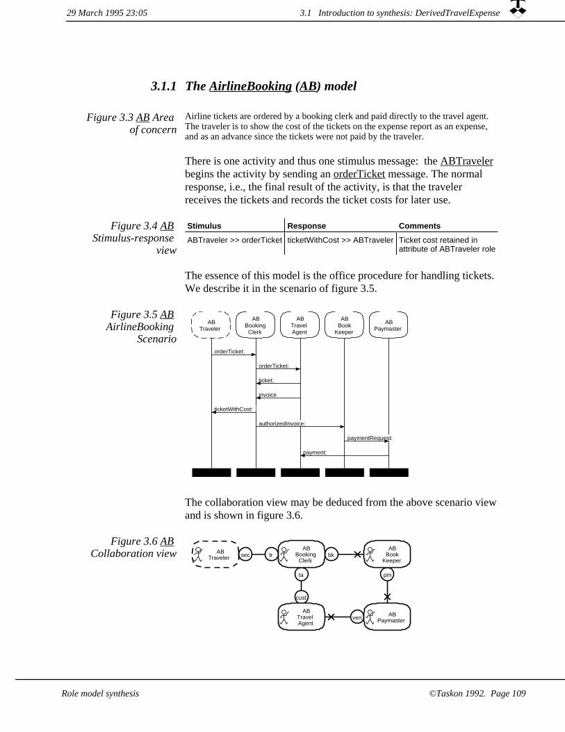
3.1.1 The AirlineBooking (AB) model
Figure 3.3 AB Area of concern
Airline tickets are ordered by a booking clerk and paid directly to the travel agent. The traveler is to show the cost of the tickets on the expense report as an expense, and as an advance since the tickets were not paid by the traveler.
There is one activity and thus one stimulus message: the ABTraveler begins the activity by sending an orderTicket message. The normal response, i.e., the final result of the activity, is that the traveler receives the tickets and records the ticket costs for later use.
Stimulus Response Comments
ABTraveler >> orderTicket ticketWithCost >> ABTraveler Ticket cost retained inattribute of ABTraveler role
Figure 3.4 AB Stimulus-response
view
The essence of this model is the office procedure for handling tickets. We describe it in the scenario of figure 3.5.
Figure 3.5 AB AirlineBooking
Scenario
ABTraveler
ABBooking
Clerk
ABTravelAgent
ABBook
Keeper
ABPaymaster
orderTicket:
orderTicket:
ticket:
invoice
ticketWithCost:
authorizedInvoice:
paymentRequest:
payment:
The collaboration view may be deduced from the above scenario viewand is shown in figure 3.6.
Figure 3.6 AB Collaboration view
ta
cust
sec tr
pm
bk
ven
ABTraveler
ABBooking
Clerk
ABTravelAgent
ABBook
Keeper
ABPaymaster
29 March 1995 23:05 3.1 Introduction to synthesis: DerivedTravelExpense
Role model synthesis ©Taskon 1992. Page 109

The precise definitions of interfaces and roles are important, but boring. We hide them within our computer-based OOram tools where the analyst can browse them as needed. The interfaces are shown textually in figure 3.7.
Figure 3.7 AB message interfaces
interface 'ABBookingClerk<ABTraveler' message 'orderTicket:' explanation "Purchase ticket(s)."
param 'ticketSpecification' type 'String'interface 'ABTraveler<ABBookingClerk'
message 'ticketWithCost:' explanation "Transmitting the ticket(s) together with cost information."
param 'package' type 'String'interface 'ABTravelAgent<ABBookingClerk'
message 'orderTicket:' explanation "Reserve specified passages and issue ticket(s)."
param 'ticketSpecification' type 'String'interface 'ABBookingClerk<ABTravelAgent'
message 'ticket:' explanation "Transmittal of ticket(s)."param 'aTicket' type 'String'
message 'invoice:' explanation "Transmittal of invoice."param 'anInvoice' type 'String'
interface 'ABBookKeeper<ABBookingClerk' message 'authorizedInvoice:' explanation "Pay this authorized ticket invoice."
param 'anInvoice' type 'String'interface 'ABPaymaster<ABBookKeeper'
message 'paymentRequest:' explanation "Pay this invoice."param 'anInvoice' type 'String'
interface 'ABTravelAgent<ABPaymaster' message 'payment:' explanation "Transmittal of payment."
param 'aCheque' type 'String'
Creating the DerivedTravelExpense (DTE) model3.1.2
We now compose a derived model from the AirlineBooking (AB) andTravelExpense (TE) models by synthesis. We call the new model DerivedTravelExpense (DTE).
Let objects play multiple roles
The essence of synthesis is that we let objects play multiple roles. So we first create an empty DerivedTravelExpense model, and then successively synthesize the TravelExpense and the AirlineBooking models into it. The area of concern for the derived model is given in figure 3.8.
Figure 3.8 DTE Areaof concern
The area of concern is the procedure for travel management including the purchase of tickets.
3.1 Introduction to synthesis: DerivedTravelExpense 29 March 1995 23:05
Role model synthesis©Taskon 1992. Page 110

Figure 3.9 DTE Environment
collaboration viewpm venau trDTE
TravelerDTE
TravelExpense
DTEPaymaster
The environment roles are still the Traveler who wants to travel, and the Paymaster who must arrange for the remuneration of the Traveler.The system itself is represented by a single, virtual role as shown in figure 3.9.
As in the TravelExpense model, a travel activity starts with the stimulus message travelPermissionRequest: from the Traveler (figure 3.10).
The ordering of a ticket is part of the TE-Traveler action. The AirlineBooking stimulus orderTicket is thus part of his travel preparations and has become an internal message in the derived model.
Figure 3.10 DTE Stimulus-response
Stimulus Response Comments
DTE-Traveler >> travelPermissionRequest: Reimbursement will be added to the nextsalary payment.
The synthesis operation is illustrated as a synthesis collaboration view in figure 3.11. The first step is to synthesize the TravelExpense model into the derived DTE model. The bordered arrows denote the synthesis relation; they go from the base roles of a base model to the corresponding derived roles of the derived model.
The basic principle of OOram role modeling is that we consider an object in the context of its collaborators; we describe both sender and receiver of every message. The derived model must, therefore, at leasthave a role corresponding to each of the roles of its base models.
The synthesis relation specifies that the derived role shall play the base role: The derived role shall fulfill the base role responsibilities and is granted its privileges: the DTE-Traveler plays the role of TE-Traveler; the DTE-Authorizer plays the role of TE-Authorizer, etc.
We similarly bind each role of the AB model onto a role in the DTE model. We had to add the DTE-BookingClerk and the DTE-TravelAgent to match the corresponding roles in the AB model, but could reuse existing DTE roles to match the remaining AirlineBooking roles. The DTE-Traveler, DTE-Bookkeeper, and the DTE-Paymaster now play two other roles and must conform to both specifications.
29 March 1995 23:05 3.1 Introduction to synthesis: DerivedTravelExpense
©Taskon 1992. Page 111Role model synthesis

pm
bo
venta
cust
bk
bo
au tr
au tr
sec
tr
bk
ven
ta
cust
sec tr
pm
pm
ABTraveler
TETraveler
TEAuthorizer
TEBookkeeper
TEPaymaster
DTETraveler
DTEBooking
Clerk
DTEBook
Keeper
DTETravelAgent
DTEPaymaster
DTEAuthorizer
TETravelExpense
DTEDerivedTravelExpense
ABAirlineBooking
ABTravelAgent
ABBooking
Clerk
ABBook
Keeper
ABPaymaster
Figure 3.11 DTE synthesis
collaboration diagram
Even in this very simple example, the graphical synthesis collaboration view is cluttered and hard to read. The compact tabular presentation view of figure 3.12 is usually better for professional system documentation.
Tabular synthesis notation more useful
Figure 3.12 DTE Synthesis Table
Derived modelDTE
Base modelTE
Base modelAB
DTE-Traveler TE-Traveler AB-Traveler
DTE-Authorizer TE-Authorizer
DTE-Bookkeeper TE-Bookkeeper AB-Bookkeeper
DTE-BookingClerk AB-BookingClerk
DTE-TravelAgent AB-TravelAgent
DTE-Paymaster TE-Paymaster AB-Paymaster
There is one row in the table for each role in the derived model. The
29 March 1995 23:053.1 Introduction to synthesis: DerivedTravelExpense
©Taskon 1992. Page 112 Role model synthesis

first column contains the names of the derived roles. There is one additional column for each base model showing the corresponding base role. Model consistency is preserved by mapping each role of thebase models onto a role in the derived model. The derived model may contain roles which are not mapped from any base model role; this is not shown in the current example.
AirlineBooking activity spliced into
ExpenseAccount action
A scenario view of the derived model activity is shown in figure 3.13.It shows how the AirlineBooking activity from figure 3.5 is merged into the TravelExpense activity of figure 2.15 on page 75??.
The key to this merger is in the method of figure 2.16 that is triggeredby the travelPermission-message. This method is split into two parts in the derived model: the first part, shown in figure 3.14, is triggered by the old travelPermission-message and ends by sending the AirlineBooking stimulus message. The second part, shown in figure 3.15, is triggered by the termination of the AirlineBooking activity and completes the actions performed by the Traveler.
DTETraveler
DTEAuthorizer
DTEBooking
Clerk
DTETravelAgent
DTEBook
Keeper
DTEPaymaster
travelPermissionRequest:
travelPermission:
orderTicket:
orderTicket:
ticket:
invoice:
ticketWithCost:
authorizedInvoice:
paymentRequest:
payment:
expenseReport:
authorizedExpenseReport:
paymentRequest:
Inserted AirlineBookingactivity
Figure 3.13 DTE scenario
29 March 1995 23:05 3.1 Introduction to synthesis: DerivedTravelExpense
Role model synthesis ©Taskon 1992. Page 113
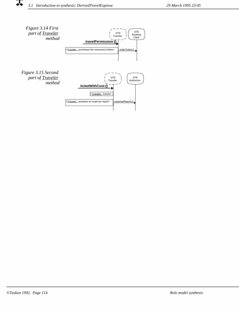
DTETraveler
DTEBooking
Clerk
travelPermission:()
<Traveler purchases the necessary tickets> orderTicket:()
Figure 3.14 First part of Traveler
method
Figure 3.15 Second part of Traveler
methodDTE
TravelerDTE
Authorizer
ticketWithCost:()
<Traveler travels>
<Traveler prepares an expense report> expenseReport:()
29 March 1995 23:053.1 Introduction to synthesis: DerivedTravelExpense
Role model synthesis©Taskon 1992. Page 114

3.2 The synthesis operation
In a nutshellWe always seem to extend the scope of our systems, and even the object models are frequently too complex to be comprehended by our limited brain capacity. The OOram technology provides abstractions that help us to divide and conquer, enabling us to handle complex phenomena in a controlled manner. We analyze different parts of a phenomenon to create simple role models, and understand each of these models separately.
Complex models are constructed from simple ones in a controlled and consistent manner. This construction, called synthesis, permits us to reuse proven models in a variety of contexts. The advantages of reuse are threefold. First, reuse reduces development cost and lead time. Second, the reuse of tested models in a controlled environment increases total quality. Third, critical phenomena can be protected by the mandatory access through validated models; thus ensuring system integrity. The main disadvantage is probably the danger of blindly building on old models, therebyloosing the fresh outlook and creativity needed to discover new insights.
As we have stressed earlier, our first approach to a new problem is to focus on its essential aspects and postpone all the trivial parts to later stages in the development. The principle of minimizing risk (FOOTNOTE: See section 4.3) suggests that we start with the parts we expect will be the hardest to get right, and continue with other parts as the harder ones get resolved. We might begin by sketching out the work flow in the organization, or creating a high-level model of the information requirements, or making a small user interface prototype, or studying high-level state machine models showing essential states and transitions in critical processes.
We may create solution islands
Many authorities recommend an orderly progression from the abstractto the concrete; create the first models on a high level of abstraction and then fill in details as work progresses. We find this excellent advice not always easy to follow, because we often have to start with some low level problem due to its high risk.
29 March 1995 23:05 3.2 The synthesis operation
Role model synthesis ©Taskon 1992. Page 115

Whatever our work process, we will end up with many different models describing different aspects of the problem and its solution. There will be overview models on a high level of abstraction, and lowlevel models showing the details of a bounded part of the problem. We do not want to extend an overview model with more and more details until we get a huge model containing everything; we want to retain the overview model and to supplant it with auxiliary descriptions of the various details.
We think in a number of distinct models, each having its own unique area of concern and representing a part of the whole.
We need many models
All our different models show different aspects of the same overall phenomenon; they are strongly linked to this common phenomenon. The models are not orthogonal, but are highly dependent because the same objects often appears in several models. We support the ideas of traceability and seamless descriptions, so that whenever we observe some information in one model, we will be able to link it to any other description of the same thing -- whether in a different model on the same level of abstraction; or in another model on a different abstraction level.
We need seamless model
interdependencies
Subclassing used for concept building and
for code sharing
Inheritance is used in object-oriented programming for two different purposes: concept building and code sharing.
When concept building, we subclass a given superclass because the concept represented by the subclass is a specialization of the concept represented by the superclass. Instances of the subclass will have all the attributes of the superclass and understand all the messages understood by the superclass in addition to possible attributes and messages defined in the subclass.
In Objectworks\Smalltalk for example, class VisualComponent defines objects which can be made visible on the computer screen. The VisualComponent subclass TextLines represent lines of stylized text; instances of TextLines understand all the VisualComponent messages, in addition to messages which manage their text attributes.
When code sharing, we subclass a given superclass quite simply because it contains useful code. All the messages defined in the superclass need not be meaningful in the context of the subclass. For example, the Objectworks\Smalltalk class Collection defines a message (at: index) which gives indexed access to its contents. Class
3.2 The synthesis operation 29 March 1995 23:05
©Taskon 1992. Page 116 Role model synthesis
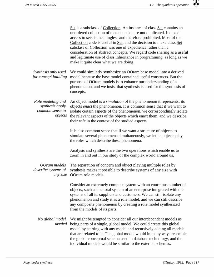
Set is a subclass of Collection. An instance of class Set contains an unordered collection of elements that are not duplicated. Indexed access to sets is meaningless and therefore prohibited. Most of the Collection code is useful in Set, and the decision to make class Set subclass of Collection was one of expedience rather than a consideration of abstract concepts. We regard code sharing as a usefuland legitimate use of class inheritance in programming, as long as we make it quite clear what we are doing.
We could similarly synthesize an OOram base model into a derived model because the base model contained useful constructs. But the purpose of OOram models is to enhance our understanding of a phenomenon, and we insist that synthesis is used for the synthesis of concepts.
Synthesis only used for concept building
Role modeling and synthesis apply
common sense to objects
An object model is a simulation of the phenomenon it represents; its objects enact the phenomenon. It is common sense that if we want to isolate certain aspects of the phenomenon, we correspondingly isolatethe relevant aspects of the objects which enact them, and we describe their role in the context of the studied aspects.
It is also common sense that if we want a structure of objects to simulate several phenomena simultaneously, we let its objects play the roles which describe these phenomena.
Analysis and synthesis are the two operations which enable us to zoom in and out in our study of the complex world around us.
The separation of concern and object playing multiple roles by synthesis makes it possible to describe systems of any size with OOram role models.
Consider an extremely complex system with an enormous number of objects, such as the total system of an enterprise integrated with the systems of all its suppliers and customers. We can still isolate any phenomenon and study it as a role model, and we can still describe any composite phenomenon by creating a role model synthesized from the models of its parts.
OOram models describe systems of
any size
We might be tempted to consider all our interdependent models as being parts of a single, global model. We could create this global model by starting with any model and recursively adding all models that are related to it. The global model would in many ways resemble the global conceptual schema used in database technology, and the individual models would be similar to the external schemas.
No global model needed
3.2 The synthesis operation29 March 1995 23:05
©Taskon 1992. Page 117Role model synthesis

We do not believe the idea of a global model is a fruitful one. We believe that everything in the real world somehow depends on everything else, so that a truly global model would be very large indeed and impossible to create or manage. Our definition of a system on page 61?? reflected this: a system is something we choose to consider as a whole during some period of observation, and a system has an environment which links it with the rest of the world without including the rest of the world in the system. Remember that we couldnot include the environment objects in our system, because we then ended up modeling the whole universe.
Finding the models We end this introduction to synthesis with the $64,000 question: How do we find the models, i.e., how do we determine that we should factor out a base model or merge several models into a larger one?
There are no hard and fast rules, but we will endeavor to give a few loosely formulated guidelines. Behind these guidelines is the fortunatefact that this is an area where the good systems analyst can demonstrate his or her excellence.
It is commonly believed that our short term memory can manage 7 ± 2notions at the same time. So we suggest the guideline that a role model should consist of 7 ± 2 roles. We should search for subphenomena to be factored out from models that are substantially larger than this. We should also search for common base models that can be synthesized into several derived models, or several times into the same model.
Conversely, we should consider merging models which contain less than five roles. Models that are used several times are exceptions to this rule -- such as the client-server models which contain just two roles in their basic form but which may be synthesized into many different derived models.
A model may depend on other models in many different ways. Generalization-specialization is an important model relationship: one model describes a general phenomenon, while other models describe its specializations. A general model could, for example, describe how we make important decisions in our organization. Two different specializations of this model could describe how we create a budget orhow we establish a major project. (FOOTNOTE: The creation of different kinds of reusable components will be discussed in chapter 5: Creating reusable components.)
Many different modelrelationships
29 March 1995 23:053.2 The synthesis operation
Role model synthesis©Taskon 1992. Page 118

Another important model relationship is aggregation: what is described as a single role on one level of abstraction is expanded into a model with several roles on the next level of detailing.
A third, very interesting model relationship is the object-subject relationship: the universe of discourse (object attributes and message parameters) in a role model may be specified as the roles of another role model.
OOram synthesis The Webster dictionary defines synthesis: "synthesis 1a: the composition or combination of parts or elements so as to form a whole c: the combination of often diverse conceptions into a coherent whole" [Webster 77].
We represent model relationships with the very general notion of role model synthesis, where we specify that individual objects shall play several roles, possibly from different role models.
We say that the base model is synthesized into the derived model. This is achieved by synthesizing every base role in the base model into a corresponding derived role in the derived model.
The concept of synthesis is as important to OOram role modeling as the concept of inheritance is to object oriented programming. In both cases, we specify that some objects shall, in some sense, be similar other objects. The main difference is that while object-oriented programming focuses on the relationship between individual classes of objects; OOram synthesis focuses on the relationships between complete patterns of objects.
The idea of objects playing multiple roles has a clear parallel in the theory of organizations: a person typically plays multiple roles such as a subordinate in a department, a member of a project, a traveler in the context of travel expenses.
Consider the file transfer protocol example of figure 2.17 on page 78??. The figure describes two models: a Client-Server model and a Source-Destination model.
We are now in the position to design three different systems by using these two models as base models and synthesizing them into three different derived models. Figure 3.16 shows a system where the Client can send files to the Server; figure 3.17 shows a system where the Client can retrieve files from the Server; and figure 3.18 shows a system where the Client can send and retrieve files to and from the Server.
Objects play multipleroles
29 March 1995 23:05 3.2 The synthesis operation
©Taskon 1992. Page 119Role model synthesis

dst src
dst src
rsp int
SourceClient
DestinationServer
Client Server
Source Destination
Client-Server base model
File transmit derived model
Source-Destination source model
Figure 3.16 A systemwhere the Client can
send files to the Server
dst src
rsp int
rsp int
DestinationClient
SourceServer
Client Server
Source Destination
Client-Server base model
File retrieve derived model
Source-Destination source model
Figure 3.17 A systemwhere the Client can retrieve files from the
Server
29 March 1995 23:053.2 The synthesis operation
Role model synthesis©Taskon 1992. Page 120
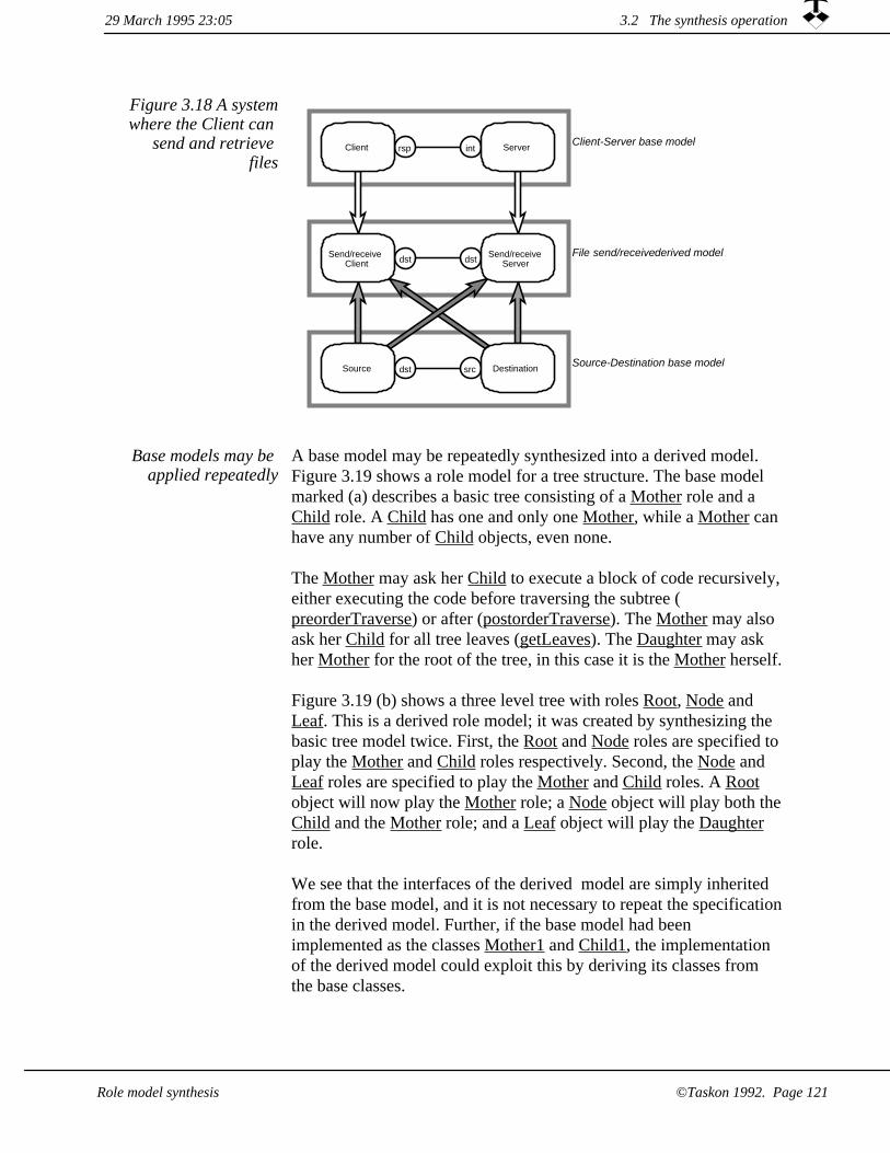
Figure 3.18 A systemwhere the Client can
send and retrieve files
dst src
dst dst
rsp int
Send/receiveClient
Send/receiveServer
Client Server
Source Destination
Client-Server base model
Source-Destination base model
File send/receive derived model
A base model may be repeatedly synthesized into a derived model. Figure 3.19 shows a role model for a tree structure. The base model marked (a) describes a basic tree consisting of a Mother role and a Child role. A Child has one and only one Mother, while a Mother can have any number of Child objects, even none.
The Mother may ask her Child to execute a block of code recursively,either executing the code before traversing the subtree (preorderTraverse) or after (postorderTraverse). The Mother may also ask her Child for all tree leaves (getLeaves). The Daughter may ask her Mother for the root of the tree, in this case it is the Mother herself.
Figure 3.19 (b) shows a three level tree with roles Root, Node and Leaf. This is a derived role model; it was created by synthesizing the basic tree model twice. First, the Root and Node roles are specified to play the Mother and Child roles respectively. Second, the Node and Leaf roles are specified to play the Mother and Child roles. A Root object will now play the Mother role; a Node object will play both theChild and the Mother role; and a Leaf object will play the Daughter role.
We see that the interfaces of the derived model are simply inherited from the base model, and it is not necessary to repeat the specificationin the derived model. Further, if the base model had been implemented as the classes Mother1 and Child1, the implementation of the derived model could exploit this by deriving its classes from the base classes.
Base models may be applied repeatedly
29 March 1995 23:05 3.2 The synthesis operation
©Taskon 1992. Page 121Role model synthesis
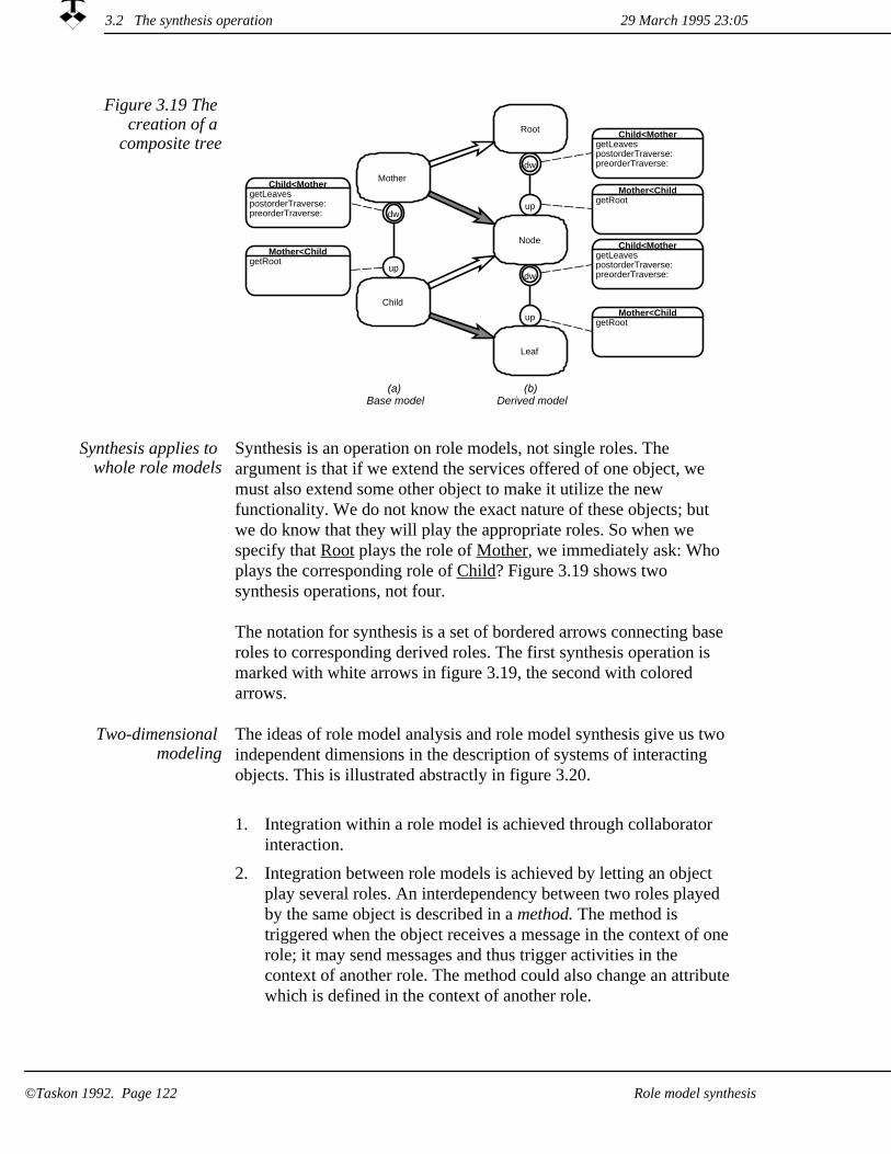
Figure 3.19 The creation of a
composite treedw
up
dw
up
dw
up
Child<MothergetLeavespostorderTraverse:preorderTraverse:
Child<MothergetLeavespostorderTraverse:preorderTraverse:
Child<MothergetLeavespostorderTraverse:preorderTraverse:
Root
Mother<ChildgetRoot
Mother<ChildgetRoot
Mother<ChildgetRoot
Node
Leaf
Mother
Child
(a)Base model
(b)Derived model
Synthesis applies to whole role models
Synthesis is an operation on role models, not single roles. The argument is that if we extend the services offered of one object, we must also extend some other object to make it utilize the new functionality. We do not know the exact nature of these objects; but we do know that they will play the appropriate roles. So when we specify that Root plays the role of Mother, we immediately ask: Who plays the corresponding role of Child? Figure 3.19 shows two synthesis operations, not four.
The notation for synthesis is a set of bordered arrows connecting base roles to corresponding derived roles. The first synthesis operation is marked with white arrows in figure 3.19, the second with colored arrows.
The ideas of role model analysis and role model synthesis give us two independent dimensions in the description of systems of interacting objects. This is illustrated abstractly in figure 3.20.
Two-dimensional modeling
Integration within a role model is achieved through collaborator interaction.
1.
Integration between role models is achieved by letting an object play several roles. An interdependency between two roles played by the same object is described in a method. The method is triggered when the object receives a message in the context of onerole; it may send messages and thus trigger activities in the context of another role. The method could also change an attributewhich is defined in the context of another role.
2.
29 March 1995 23:053.2 The synthesis operation
Role model synthesis©Taskon 1992. Page 122

Horizontal integration(Analysis):
Collaborator interactionwithin Role Model.
Vertical Integration(Synthesis):Message
triggers Methodwhich sends (stimulus) Messageor changes Attribute
Figure 3.20 Two-dimensional
modeling
The purpose of role model analysis is to understand a phenomenon and specify its possible implementation. We spend considerable effortto persuade ourselves and others that the model is a faithful and correct representation of the phenomenon, and that the implementation will fill our needs and be without serious flaws.
We want to retain base model
correctness in the derived model
Assuming that a base model is correct in all the aspects we care to consider, we would like this correctness to be retained in a model that is derived from it by synthesis so that we do not need to repeat the correctness considerations. We will distinguish between three kinds ofcorrectness:
That the derived model conserves the static correctness of the base model.
1.
That the derived model conserves the dynamic correctness of the base model.
2.
That the derived model correctly reflects the semantics of the base model.
3.
Static correctness can be retained
automatically
It is fairly easy to create an OOram tool that conserves static correctness through a synthesis operation. Specifically:
All roles in a base model are mapped onto corresponding roles in the derived model.
1.
The attributes of the base roles are retained as attributes of the corresponding derived roles.
2.
3.2 The synthesis operation29 March 1995 23:05
Role model synthesis ©Taskon 1992. Page 123

All ports in a base model are mapped onto corresponding ports in the derived model. The cardinalities of the ports in the derived model must be consistent with the cardinalities of the corresponding ports in the base model: the minimum cardinality of a derived port may be equal to or greater than the minimum cardinality of the corresponding base port, and the maximum cardinality of a derived port may be equal to or less than the maximum cardinality of the corresponding base port.
3.
4. All interfaces defining the messages that are permitted to be sent from a base port are retained as identical interfaces defining messages that are permitted to be sent from the corresponding derived port (except for possible renaming of messages).
Due diligence required to retain
dynamic correctness
Dynamic correctness means that the base model message sequencing specifications are retained in the derived model. We have defined the notions of a method as the action taken by a role in response to a received message, and an activity as the sequence of actions taken by a structure of roles in response to a stimulus message. The dynamic correctness of a role model is closely linked to the dynamic correctness of its activities, and the preservation of dynamic correctness through a synthesis operation means the preservation of the integrity of the activities.
Base model semantics shall be
retained in all derived models
Figure 2.3 on page 57?? illustrated how a manifest model in some way is a representation of a mental model. We cannot automatically check that this representation is correct; correspondence can only be checked through mental processes. For example, consider that we have a general Tree model with a Root role collaborating with any number of Leaf roles. Further, assume that we want to model a mother- child relationship, and decide to derive the Mother-Child model from the Tree base model. We can formally check that the Mother-Child model has the properties of the Tree model, but we cannot formally check that either model corresponds to our mental ideas of mothers and children.
For all proper applications of the OOram synthesis operation, the analyst must make sure that the meaning of the derived model is consistent with the meanings of all its base models.
3.2 The synthesis operation 29 March 1995 23:05
©Taskon 1992. Page 124 Role model synthesis

Static correctness guarantees that we only send messages through a port that are defined in one of its interfaces. But it does not prevent us from specifying a method in the context of one of the object's roles that sends an arbitrary message associated with another of its roles. We may, therefore, break into the middle of a base activity and play havoc with any argument about its dynamic correctness, and the time sequences of messages observed in a derived model may violate the base model activity specifications. This may be acceptable. It could bethat we want to specify a new activity in the derived model that merely uses some of the base model functionality. We call it unsafe synthesis, since we have to recheck the dynamic correctness of the derived model. The antonym is safe synthesis. This is synthesis wherewe can trust that the dynamic correctness of the base model is retainedin the derived model.
Safe and unsafe synthesis
Safe synthesis Else Nordhagen and Egil Andersen of the Department of Informatics at the University of Oslo are both exploring different formal foundations for role modeling. Parts of their work are concerned with describing the synthesis of dynamic behavior, which is a deep research topic. It will be premature to report their results here, so we refer to their preliminary publications(FOOTNOTE: [E. Andersen 92], [Nordhagen 89], [Nordhagen 95]).
The essence of safe synthesis is that the integrity of the base model activities must be retained in the derived models. The activity must bestarted by its stimulus message and then permitted to run its course without interference to its completion. The key to the success of safe synthesis is that it does not matter what other activities the objects perform before, during, or after a base model activity, as long as they do not interfere with it in any way.
Safe synthesis preserves integrity of
base activity
29 March 1995 23:05 3.2 The synthesis operation
©Taskon 1992. Page 125Role model synthesis

Summing up, all base model roles are mapped onto derived model roles in the synthesis operation.
In safe synthesis, the integrities of the base model activities are retained in the derived model. This means that a base model activity can only be triggered by its stimulus message. This stimulus message can either become a stimulus message in the derived model; or it can be sent from one of the methods in the derived model.
In the first kind of safe synthesis, an environment role of a base modelis synthesized into an environment role of the derived model, and the stimulus messages of the base model becomes stimulus messages of the derived model.
In the second kind of safe synthesis, an environment role in the base model is synthesized into a system role in the derived model. A base model stimulus message is sent from a method in the derived model and becomes part of its normal message flow.
Environment roles may become system
roles in derived model
We claim that these two synthesis constructs retain activity integrity, but stress that further research may reveal anomalous cases which render the constructs unsafe. The constructs have been formulated for synchronous message semantics, further work is needed to identify safe constructs for parallel processes. We also believe that there are a number of other safe constructs, so do not take this list as being the final one.
1. activity superposition is a kind of safe synthesis where a base model stimulus messages is retained as a stimulus message in the derived model. The base model activity is retained unchanged as aderived model activity; independent of all other activities in the derived model.
activity aggregation a kind of safe synthesis where a base model activity details a method in the derived model. It is very similar toa closed subroutine: the method sends the base model stimulus message and the corresponding base model activity is permitted torun to completion without interference. The method continues after the base activity has terminated.
2.
3.2 The synthesis operation 29 March 1995 23:05
Role model synthesis©Taskon 1992. Page 126
Aggregation: Linking models on different levels of abstraction
3.2.1
The principle of hierarchical decomposition is an important idea for the study of complex systems. Indeed, some authors hold it to be a fundamental principle of nature itself (FOOTNOTE: A good example is [Booch 94]): A plant consists of three major structures (root, stems,and leaves), and each of these can be decomposed into its own substructure.
Aggregation is an important modeling
idea
While we agree that hierarchical decomposition is important and useful, we cannot agree that it is a part of nature. The plant does not know about roots, stems, and leaves; these ideas are useful to the botanist and the schoolteacher and are so widely published so as to become an established truth.
The idea of hierarchical decomposition belongs to the world of models rather than to the real world. More specifically, we regard hierarchical decomposition to be one of the principles for organizing role models. Looking at it this way, we can get the benefits of hierarchical decomposition within the scope of some role models. We do not insist that the hierarchy shall be pervasive, the hierarchy may not be visible if we study the object structure from some other perspective.
Let us return for a moment to figure 2.3 on page 57??. Like any other model, a hierarchical model can neither be right nor wrong, just more or less useful for a given purpose. The distinction between root and stem is useful if I want to cook carrots for dinner. It could be useless if I want to study the flow of nutrients through the plant, and I had better select a more appropriate model highlighting the vascular system.
Hierarchical decomposition and aggregation, often called the consists of - part of relationship, is an artifact of our thoughts: we choose to consider certain objects as being the parts of another object in the context of certain role models. This is illustrated conceptually in figure 3.21 (a).
There are two criteria that should alert you to the possibility of factoring out sub-phenomena from a model on any level. One is that the model gets overly complex. We prefer models to have somewhere
3.2 The synthesis operation29 March 1995 23:05
Role model synthesis ©Taskon 1992. Page 127

between 5 and 9 roles; it will then fit nicely in our short term memory and on a computer screen. Another criterion is that if the model displays repeated patterns of similar structures, these patterns should be described in separate models and removed from the main model.
Good choices of areas of concern, and thus of models, are usually found in an iterative process. If a model gets too complex, we split it up into smaller models. If we get too many very simple models, we combine them into larger ones.
Figure 3.21 Considering certain roles to be parts of
another role
(a) Encapsulated aggregation(Invisible parts)
(b) Embedded aggregation.(Visible parts)
Outer system
Part systemX
Outer system
Part system
Aggregate roles are shown as gray, while other roles of the outer system are shown as white, and other part roles are shown as black.
We represent the idea of aggregation as a pair of role models: When considering the outer system, the aggregate is represented as a single role. When considering the part system, the aggregate is represented as a role model showing its parts. The single role in the outer system is found as the environment role of the part system.
The OOram technology supports three different kinds of aggregation: encapsulation, where the parts are invisible from outside the aggregate role; embedding, where some parts are visible; and virtual, where the aggregate role is an artifact of thought not represented as anobject in the object structure. All kinds imply that different models have common objects, as we shall see in the following.
Encapsulation hides the parts within a
single role
A role in the outer system may completely encapsulate the roles of thepart system. The part roles are then invisible in the external perspective of the outer system. This is called encapsulated aggregation; there is one shared object as can be seen from the object model of figure 3.21 (a) and the corresponding role models of figure 3.22 (a).
We see that the object marked 'X' plays two roles: it is a system role
3.2 The synthesis operation 29 March 1995 23:05
©Taskon 1992. Page 128 Role model synthesis
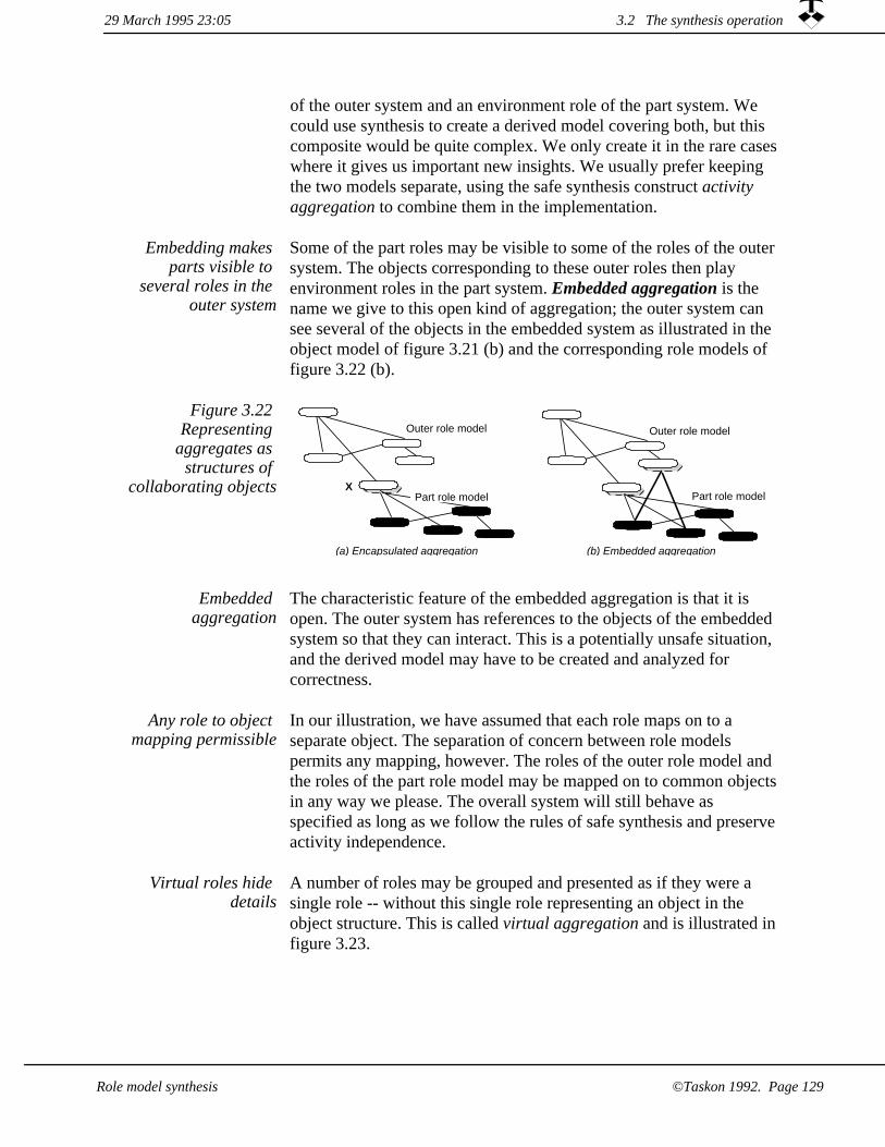
of the outer system and an environment role of the part system. We could use synthesis to create a derived model covering both, but this composite would be quite complex. We only create it in the rare cases where it gives us important new insights. We usually prefer keeping the two models separate, using the safe synthesis construct activity aggregation to combine them in the implementation.
Embedding makes parts visible to
several roles in the outer system
Some of the part roles may be visible to some of the roles of the outer system. The objects corresponding to these outer roles then play environment roles in the part system. Embedded aggregation is the name we give to this open kind of aggregation; the outer system can see several of the objects in the embedded system as illustrated in the object model of figure 3.21 (b) and the corresponding role models of figure 3.22 (b).
Figure 3.22 Representing
aggregates as structures of
collaborating objects
(a) Encapsulated aggregation (b) Embedded aggregation
Outer role model
XPart role model
Outer role model
Part role model
The characteristic feature of the embedded aggregation is that it is open. The outer system has references to the objects of the embedded system so that they can interact. This is a potentially unsafe situation, and the derived model may have to be created and analyzed for correctness.
Embedded aggregation
In our illustration, we have assumed that each role maps on to a separate object. The separation of concern between role models permits any mapping, however. The roles of the outer role model and the roles of the part role model may be mapped on to common objectsin any way we please. The overall system will still behave as specified as long as we follow the rules of safe synthesis and preserve activity independence.
Any role to object mapping permissible
Virtual roles hide details
A number of roles may be grouped and presented as if they were a single role -- without this single role representing an object in the object structure. This is called virtual aggregation and is illustrated infigure 3.23.
29 March 1995 23:05 3.2 The synthesis operation
Role model synthesis ©Taskon 1992. Page 129

virtual role
Figure 3.23 Virtual roles a cluster of roles as a single
aggregate
Many words have been written and many pictures flashed on overheadprojectors to describe the notion of a client-server system architecture.Clients are typically personal computers or workstations running the user's software, while the servers are background computers linked to the clients through communication channels and managing shared data with their associated programs. We recognize the client-server architecture as an essentially object-oriented architecture; role modeling is ideally suited for describing both the client and the server parts, and encapsulated aggregation is the composition construct which will safely combine the two and permit us to change focus between the client and the server as needed.
Client-server architecture
There is still no consensus as to the best division of responsibility between the client and the server. We see that any case of encapsulated aggregation can be implemented in a client-server architecture. The positioning of the communication path within the overall system is an engineering decision. We will describe our proposal in chapter 7.3: Task/Tool/Service model.
Attributes and message parameters3.2.2
A role model describes how objects interact to achieve some purpose. The subject of their interaction is represented as message parameters and object attributes.
Attributes and parameters representthe subject of object
interaction
Message parameters may be grouped as follows:
Nonobject values. A parameter may represent something we consider to be outside our world of objects. It could be concrete, such as a paper form. Or it could be abstract, such as a value in a relational database. We also consider basic data types such as Integer and String to belong to this group.
1.
29 March 1995 23:053.2 The synthesis operation
Role model synthesis©Taskon 1992. Page 130

References within current role model. A parameter may reference a role in the current role model. An example could be Eve in this message to Peter: "Your travel authorizer will be Eve". The receiver will normally use the parameter to update the value of one of its ports. The interaction with these roles is described by the role model views discussed at length in chapter 2: Role modeling.
2.
References within another role model. A parameter may referencea role in another role model. This other role model then defines part of the universe of discourse for our current role model. The receiver will normally use the parameter to update the value of one of its attributes.
3.
Role attributes could be defined in the same way. References to roles in the current role model are represented as ports, and other attributes are either nonobject values or role references to another role model.
The third group of parameters provides an interesting relation between role models: the objects of the parameter role model constitute (part of) the subject of interaction of the current role model.
Messages carry the parameter values from one role to another, and it is only possible to send messages to a parameter role from one of the current roles. This current role must either have a port referencing the parameter; or the parameter role must be encapsulated within the current role as illustrated in figure 3.24 (a).
An interesting relationship between
role models
Figure 3.24 Representing an
attribute or a parameter as an
encapsulated role model
Current role model
Subject role model
XCurrent role
The current role model may sooner or later want to send a message to trigger an activity in the parameter model. This message must be a stimulus message to keep the synthesis safe. Its sending role must, therefore, be an environment role in the parameter model.
It is important to realize that the objects of the current role model and the objects of the parameter role model all exist in the same world of
3.2 The synthesis operation29 March 1995 23:05
Role model synthesis ©Taskon 1992. Page 131

interacting objects. The distinction between the role models is an artifact of our choice of role model abstractions and is a result of our separation of concern. The object marked 'X' in figure 3.24 plays tworoles: one in the Current role model and one in the Subject role model. The two role models are integrated through the methods of object 'X' sending stimulus messages to the subject role model, and the role models are otherwise independent.
The parameter and attribute relationships link a model with its universe of discourse. We will use it in the case study in chapter 7: Development of a business information system to link a model of a human organization to a model of its information base, but the concept is recursive and can be applied on as many levels as you can keep track of.
Object-subject relationship very
general
3.2.3 Safe and unsafe synthesis of the travel example models
Let us illustrate safe and unsafe synthesis by an example. We slightly modify the DerivedTravelExpense model so that the Authorizer and the BookingClerk are played by the same derived role called the Manager. The role model with a few critical interfaces is illustrated in figure 3.25.
ta
cust
sec tr bo
pm
ven
Traveler
ABTravelAgent<ABBookingClerkorderTicket:
Messages sentexpenseReport:orderTicket:travelPermissionRequest:
Manager BookKeeper
TravelAgent Paymaster
Figure 3.25 Simple synthesis example
3.2 The synthesis operation 29 March 1995 23:05
©Taskon 1992. Page 132 Role model synthesis

There are two activities in this example: the TravelExpense activity describes the overall management of a business trip, and the AirlineBooking activity describes the booking and payment of airline tickets. These activities may be combined in different ways:
activity superposition (figure 3.26). The Traveler could order tickets independently of the authorization process, for example, because it would be too late to leave it until the travel was authorized, or because there are many other situations where tickets need to be ordered. (The base models would have to be extended with travel cancellation capabilities to cater to the case when travel permission was refused).
1.
activity aggregation (figure 3.27). The synthesis described in the previous section was an example of activity aggregation: the AirlineBooking activity was started from an action in the TravelExpense activity.
2.
unsafe synthesis (figure 3.28). The Manager in the role of Authorizer receives a travelPermissionRequest message. She could decide to grant the permission and also to be extra helpful: she dons the hat of BookingClerk and orders the required tickets. The AirlineBooking model assumed that the initiative was with the Traveler, therefore we have to reconsider the dynamic behavior of the derived model to protect ourselves against surprises.
3.
29 March 1995 23:05 3.2 The synthesis operation
Role model synthesis ©Taskon 1992. Page 133

Figure 3.26 Activity superposition
illustration
AirlineBooking
TravelExpense
Traveler Manager Bookkeeper Paymaster TravelAgent
Traveler Bookkeeper Paymaster TravelAgentBookingClerk
Traveler Authorizer Bookkeeper Paymaster
DerivedTravelExpense
stimulus
stimulus
The Traveler could order tickets independently of the authorization process, for example, because it would be too late to leave it until the travel was authorized, or because there are many other situations where tickets need to be ordered. (The base models would have to be extended with travel cancellation capabilities to cater to the case when travel permission was refused).
Note: The messages are sent between the objects, but we think of them as being sent in the appropriate base model roles.
TravelExpense
Traveler Manager Bookkeeper Paymaster TravelAgent
Traveler Bookkeeper Paymaster TravelAgentBookingClerk
Traveler Authorizer Bookkeeper Paymaster
DerivedTravelExpense
AirlineBooking
stimulus
Figure 3.27 Activity aggregation
illustration
The synthesis described in the previous section was an example of activity aggregation: the AirlineBooking activity was started from an action in the TravelExpense activity, and the two activities were permitted to run independently.
29 March 1995 23:053.2 The synthesis operation
Role model synthesis©Taskon 1992. Page 134

AirlineBooking
TravelExpense
Traveler Manager Bookkeeper Paymaster TravelAgent
Traveler Bookkeeper Paymaster TravelAgentBookingClerk
Traveler Authorizer Bookkeeper Paymaster
DerivedTravelExpense
unsafe message!
??????
stimulus
Figure 3.28 Unsafe synthesis illustration
The Manager in the role of Authorizer receives a travelPermissionRequest message.She decides to grant the permission and also to be extra helpful: she dons the hat of BookingClerk and orders the required tickets. The AirlineBooking model assumed that the initiative was with the Traveler, therefore we have to reconsider the dynamic behavior of the derived model to protect ourselves against surprises.
Note the unsafe message entering in the middle of the booking activity. The first message is bypassed, so the Traveler is not prepared for the last message.
29 March 1995 23:05 3.2 The synthesis operation
Role model synthesis ©Taskon 1992. Page 135

3.3 Basic OOram concepts and notation for role model synthesis
In a nutshellWe here give a technical description of the synthesis operation as seen in each of theOOram views.
The OOram technology offers a large number of different views on the role models as described in chapter 2.5 on page 90??. All the views are somehow affected by the synthesis operation, and we will discuss each of them in the following sections.
Synthesis affects all views and
perspectives
As discussed in chapter 3.2, the static and semantic correctness of the base models can be carried over to the derived model automatically. We suggested two constructs that preserve the dynamic correctness of the base models. These two constructs, called activity superposition and activity aggregation, will be the focus of this chapter.
We focus on Safe Synthesis
3.3.1 The Inheritance and Role List views
The purpose of the inheritance views is to show the base model -- derived model relationships between role models.
There are three different views showing the inheritance (export -- import) relationships between role models:
Three inheritance views
The Synthesis view shows any number of role models and the inheritance relationships between them without giving any internal details.
1.
2. An Inheritance Collaboration view shows two or more role models and the inheritance relationships between their roles.
An Inheritance Table gives the same information in tabular form.3.
An OOram language inheritance specification gives the same information in textual form.
4.
29 March 1995 23:053.3 Basic OOram concepts and notation for role model synthesis
©Taskon 1992. Page 136 Role model synthesis
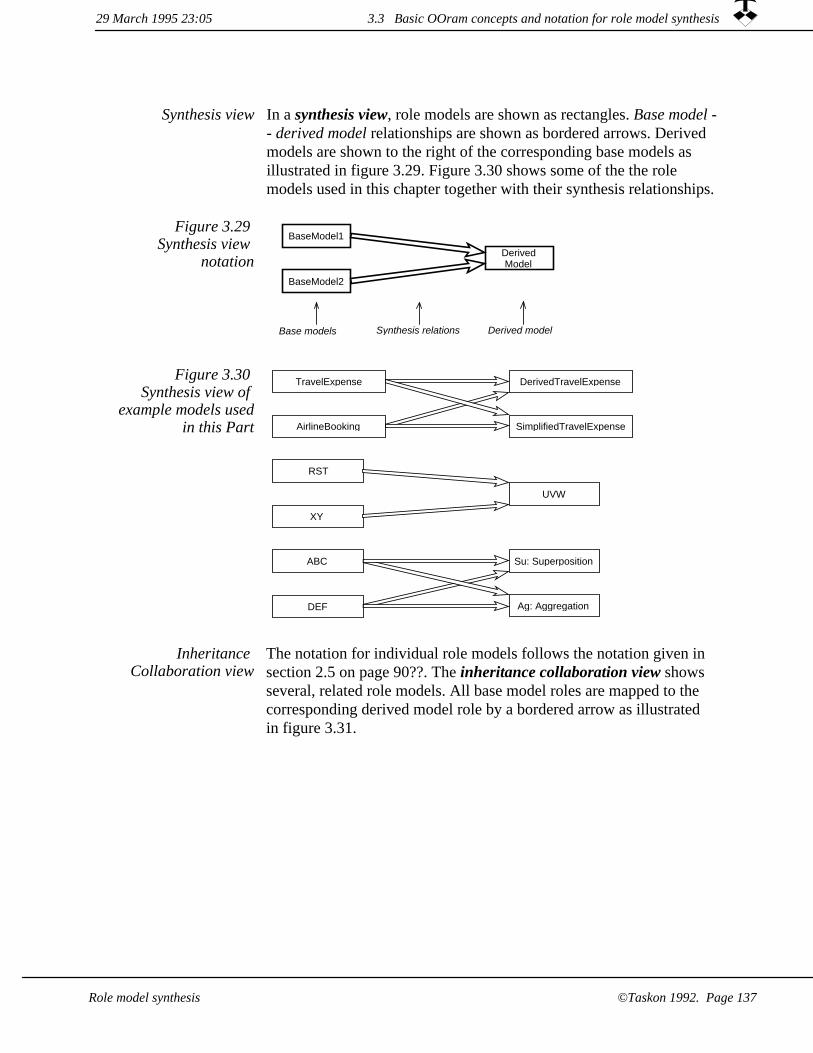
In a synthesis view, role models are shown as rectangles. Base model -- derived model relationships are shown as bordered arrows. Derived models are shown to the right of the corresponding base models as illustrated in figure 3.29. Figure 3.30 shows some of the the role models used in this chapter together with their synthesis relationships.
Synthesis view
Base models Derived modelSynthesis relations
DerivedModel
BaseModel1
BaseModel2
Figure 3.29 Synthesis view
notation
DerivedTravelExpense
Ag: Aggregation
Su: Superposition
SimplifiedTravelExpense
TravelExpense
AirlineBooking
ABC
DEF
RST
XY
UVW
Figure 3.30 Synthesis view of
example models usedin this Part
The notation for individual role models follows the notation given in section 2.5 on page 90??. The inheritance collaboration view shows several, related role models. All base model roles are mapped to the corresponding derived model role by a bordered arrow as illustrated in figure 3.31.
Inheritance Collaboration view
3.3 Basic OOram concepts and notation for role model synthesis29 March 1995 23:05
©Taskon 1992. Page 137Role model synthesis

y
x
y
x
s
t r
t r
s
r
s
r
R T
S
X
Y
U W
V
Base modelRST
Derived modelUVW
Base modelXY
Figure 3.31 ExampleInheritance
Collaboration view
An inheritance table is shown in table 3.1. It has one row for each role in the derived model. The first column shows the roles of the derived model, while the other columns show the corresponding roles in the base models. Note that all the roles of the base models must be accounted for in the derived model, but the reverse need not be true.
Table 3.1 Example Inheritance Table
Derived modelUVW
Base modelRST
Base modelXY
Role U R
Role V S Y
Role W T X
The inheritance mapping can be specified as an OOram language inheritance specification as part of the definition of the derived role model. The full language is defined in Appendix A; and an example inheritance specification is shown in figure 3.32.
29 March 1995 23:053.3 Basic OOram concepts and notation for role model synthesis
©Taskon 1992. Page 138 Role model synthesis

Figure 3.32 ExampleOOram language
inheritance specification
role_model 'RST' explanation "Example three-role base model."role_model 'XY' explanation "Example two-role base model."role_model 'UVW' explanation "Example 3-role derived model."
base_model 'RST''R' -> 'U''S' -> 'V''T' -> 'W'
base_model 'XY''X' -> 'W''Y' -> 'V'
3.3.2 Synthesis in Area of Concern view
No automatic composition of Area
of Concern
An Area of Concern is a free text description of the modeled phenomenon. Automatic synthesis of the derived Area of Concern is not possible. (Except for a simple concatenation of the constituent texts.) It is the responsibility of the analyst to specify the Area of Concern for the derived model and to ensure that it is semantically consistent with the Areas of concern of the base models.
Manual composition of Area of Concern
The synthesis operation is a very general operation and may support many different relationships between the derived and its base models, but the phenomena described by the base models will always, in somesense, be parts of the phenomenon described by the derived model. The Area of Concern of the derived model will, therefore, explicitly or implicitly encompass the Areas of Concern for the base models.
The synthesis of the areas of concern for our two safe synthesis constructs are as follows:
1. Activity Superposition. The derived model's area of concern includes the area of concern of its base models. For example, we could have two different TravelExpense models for national and international travel. We could use synthesis to derive a model thatcovered both cases.
2. Activity Aggregation. A base model elaborates an action (method)in the derived model. As an example, consider that our AirlineBooking model elaborates one of the Traveler role's actions in the TravelExpense model. The area of concern of the detail base model may be invisible in the area of concern of the derived model.
29 March 1995 23:05 3.3 Basic OOram concepts and notation for role model synthesis
Role model synthesis ©Taskon 1992. Page 139

3.3.3 Synthesis seen in the Environment and Stimulus-Response views
Retain or explain base model stimuli
A stimulus message from an environment role in the base model may be handled in one or both of the following ways in the derived model:
Superposition. A stimulus message in a base model may become astimulus message in the derived model. The corresponding base environment role must then be mapped onto a derived environment role.
1.
Aggregation. A stimulus message in a base model may be sent from one of the methods of the corresponding role in the derived model. The derived role can in this case be either a system role or an environment role; the base model environment role sending thestimulus message must have been mapped onto it.
2.
Activity superposition is illustrated in in figure 3.33. The stimulus andresponse messages of the base models are retained as stimulus and response messages of the derived model. The base model environmentroles have here been mapped onto common derived environment roles, but they could alternatively be mapped onto different derived environment roles.
Figure 3.33 Superposition
environment view
f ee d
c bb a
f eb dSuAD SuCF
A B C
D E F
Superimposedsystem
Activity aggregation is illustrated in figure 3.34. The DEF model is hidden within the AggregationSystem where its activity is part of a method in a derived role.
3.3 Basic OOram concepts and notation for role model synthesis 29 March 1995 23:05
Role model synthesis©Taskon 1992. Page 140

Figure 3.34 Aggregation
environment viewc b
e d
b a c b
b a
f e
AgA Aggregationsystem
AgC
A B C
D E F
3.3.4 Synthesis seen in the Collaboration view
There are no formal relationships between the responsibilities of the roles of the derived model and the roles of the base models, but the analyst should ensure that they are consistent. The general restrictionson roles, ports and cardinalities mentioned previously also hold for the collaboration views:
Formal collaboration view
dependencies between synthesized
models
All roles in the base models are mapped onto roles in the derived model.
1.
The attributes of the base model roles are included in the attributes of the corresponding derived model roles.
2.
3. The collaborators of the derived model roles will include the collaborators of the corresponding base model roles.
4. All ports in the base models are mapped onto corresponding portsin the derived model. The cardinalities of the ports in the derived model must be consistent with the cardinalities of the corresponding ports in the base model. Specifically, the minimumcardinality of a port in the derived model must be equal to or greater than the minimum cardinality of the corresponding ports in the base models, and the maximum cardinality of a port in the derived model must be equal to or less than the maximum cardinality of the corresponding ports in the base models.
29 March 1995 23:05 3.3 Basic OOram concepts and notation for role model synthesis
Role model synthesis ©Taskon 1992. Page 141

The graphical notation for the Inheritance Collaboration view was described in figure 3.31. The Inheritance table in table 3.1 is used to describe the inheritance relationships in most practical work; the collaboration view of the derived model then looks just like any other collaboration view.
Notation
Figure 3.35 illustrates activity superposition in the collaboration view.The base model environment roles have here been mapped onto common derived environment roles, but they could have been mappedonto different roles in the derived model.
The base model system roles have been mapped onto a common role in the derived model, but they could have been mapped onto different roles.
Figure 3.35 Superposition
collaboration view
f e
b a
b a c b
e d
c e
A B C
D E F
SuAD SuBE SuCF
Figure 3.36 illustrates activity aggregation in the collaboration view. The derived model constitutes the base model environment: the derived system role AgBDF plays the environment roles D and F. It sends the stimulus message of the DEF model from one of its methods, and receives the response message from the DEF activity.
29 March 1995 23:053.3 Basic OOram concepts and notation for role model synthesis
©Taskon 1992. Page 142 Role model synthesis

c b
e d
e
d
b a
c bb a
f e
A B C
AgA AgBDF AgC
AgE
D E F
Figure 3.36 Aggregation
collaboration view
3.3.5 Synthesis seen in the Scenario view
We illustrate the safe synthesis of Scenarios by assuming the pair of extremely simple activities for the base models shown in figures 3.37 and 3.38.
Figure 3.37 ABC Scenario A B C
ab1:
bc2:
D E F
de1:
ef1:
Figure 3.38 DEF Scenario
In activity superposition, the base model activities become derived model activities. The corresponding scenarios are simply carried unchanged into the derived model as illustrated in figure 3.39.
Scenario superposition
29 March 1995 23:05 3.3 Basic OOram concepts and notation for role model synthesis
Role model synthesis ©Taskon 1992. Page 143

SuAD SuBE SuCF
ab1:
bc2:
Su-Scenario-a
Su-Scenario-bSuAD SuBE SuCF
de1:
ef1:
Figure 3.39 Scenariosuperposition
Scenario aggregation
In activity aggregation, a base model stimulus message is sent from within a derived model method. We have illustrated this by sending the DEF stimulus message from the derived method for message ab1. The corresponding scenario is shown in figure 3.40.
The DEF stimulus message is sent from within the derived model method for message ab1: in role AgH. The DEF activity is thus completely embedded in this method.
AgA AgBDF AgE AgC
ab1:
de1:
ef1:
bc2:
Aggregated DEF activity.
Figure 3.40 Scenarioaggregation
Synthesis seen in the Interface view3.3.6
The interfaces associated with a port in the derived model include all interfaces associated with the corresponding ports in the base models.
All base model interfaces included
29 March 1995 23:053.3 Basic OOram concepts and notation for role model synthesis
Role model synthesis©Taskon 1992. Page 144

Base model interfaces immutable
Base model interfaces are immutable in the derived model: messages may neither be added nor removed. It is possible to rename the derived interfaces and messages; but this adds to the confusion and is avoided if possible. (The exception is when there are name conflicts between base models which are synthesized into a common, derived model).
Messages can only be added in new
interfaces
New messages can only be added to interfaces which are defined in the derived model.
It is usually not necessary to repeat the specification of the imported interfaces in the documentation of the derived model, but they may beincluded if this improves readability.
Imported interface documentation
optional
3.3.7 Synthesis of method Specification view
When a base role is synthesized into a derived role, all its collaborators and the corresponding message interfaces are synthesized correspondingly. The derived role has to provide a method for every message understood by the base role. The default is to retain the base role methods; the behavior of the derived model willthen correspond to the behavior of the base model.
Default: Base method becomes
derived method
The derived role may redefine one or more methods, causing the derived model to behave differently from the base model. In principle,the derived method can do anything. It can for example send any message on any port regardless of where that message was originally defined. This leads to unsafe synthesis, where our understanding of the base model behavior does not help us understand the behavior of the derived model.
Unsafe method override possible
The Activity superposition safe synthesis construct is illustrated in figure 3.26. The stimulus messages of the base models become stimulus messages of the derived model, and the activities of the base models become activities of the derived model. No method override isrequired in the derived model, but certain kinds of overrides are permissible and may be desirable.
Activity superposition
The detailed method logic may be influenced by the combination of
3.3 Basic OOram concepts and notation for role model synthesis29 March 1995 23:05
©Taskon 1992. Page 145Role model synthesis

roles played by the object. The procedure followed by a travel Authorizer who is a department head could, for example, be different from the procedure followed by a travel Authorizer who is a project manager.
The detailed behavior often depends on the value of an attribute belonging to another role played by the same object. The Traveler stores the cost of the airline ticket as part of the AirlineBooking role model. When filling in the expense account, the Traveler adds this amount as an expense and deducts it as an advance.
The activity aggregation safe synthesis construct is illustrated in figure 3.27. The activity of the second base model shall be part of a method in the first model. This method must be modified in the derived role to send the required stimulus message and wait for its completion. In addition, the overrides permissible in the superpositionconstruct are also permissible here.
Activity aggregation
29 March 1995 23:053.3 Basic OOram concepts and notation for role model synthesis
©Taskon 1992. Page 146 Role model synthesis

Chapter 4Bridge to implementation
This chapter has been written for computer programmers. It tells you how to create an implementation with the functionality specified in one or more role models.
Implementations may be created by different technologies: Business processes may, for example, be manual or computer assisted, and computer programs may be specified in a variety of different programming languages. The OOram method is basically independent of the implementation technology, but the shrewd analyst willlet the intended implementation technology color the details of the analysis.
We will not attempt to cover all possible implementation technologies here, but will focus on computer implementation in an object-oriented programming language. The presentation covers implementation in Smalltalk and C++. The OOram methodhas also been used successfully to specify programs written in other languages suchas C and Eiffel; and also to specify manual business processes in large organizations.
Introduction to implementationObject modeling from a programmer's point of viewA simple class inheritance exampleWhy we need high level descriptions
The relationship between a role model and its implementationImplementing the rolesImplementing the ports and interfacesImplementing the methods and actions
The implementation processChoice of programming language
29 March 1995 23:05
©Taskon 1992. Page 147Bridge to implementation

Introduction to implementation4.1
In a nutshellWe have earlier stressed the value of divide and conquer. Objects play many roles and our descriptions are materially simplified when we focus on one function at the time. We now get to the stage where we have created the role models and want to combine them in an implementation. This is also the time for filling in the details. Inthe role models, we reason about overall functionality. We are now allowed to focuson one class at the time and get its details right.
The implementation stage is the acid test for our separation of concern: successful role models only interact in a few, easily controlled points. There is something suspicious with our role models if we need to reconsider the whole when we implement the details.
Figure 4.1 Typical models on different levels of abstraction
Systemimplementation
(programs)
Systemdesignmodel
Systemrequirements
model
Systemuser
model
The focus of this chapter
Transition between design and
implementation
The art of computer programming is outside the scope of this book. Our interest focuses on the transition between the abstract design descriptions and the implementation, with special emphasis on how we can maintain the consistency between the different levels of description as illustrated in figure 4.1.
A simple problem can be solved with simple means. If we want to build a birdhouse, we take a few pieces of wood and nail them together. If we need to count how many times differen characters occur in a text file, we write a simple program to do the counting.
Simple solution to simple problem
29 March 1995 23:054.1 Introduction to implementation
©Taskon 1992. Page 148 Bridge to implementation

Complex problems may have equally simple solutions. A builder can create temporary living quarters for his crew by simply stacking a number of prefabricated huts. A Unix expert can specify very powerful functionality by linking a number of existing programs through a shellscript. Programmers routinely invoke proven library functions to reduce the apparent complexity and improve the quality of their programs.
The top-down approach for hierarchical decomposition was introduced by [Wirth 71] and has later been advocated by many methodologists. (FOOTNOTE: Aggregation and hierarchical decomposition was discussed in section 3.2.1). Hierarchical decomposition has a long history of success stories, because hierarchical models are easy to understand, and help partition large problems into smaller ones.
Hierarchical decomposition for simple solution to complex problem
The main difficulty with hierarchical decomposition is that there are so many problems that are not amenable to it. On the human level, wehave studied an object pattern that describes the handling of travel expense accounts. Other models would be needed to describe the myriad of other functions in an enterprise. A few examples are design,production, budgeting, accounting, and materials management.
Horizontal decomposition splits
complex problem into several simpler
ones
These models all belong on the same level, so they cannot be organized in a hierarchy. Each model can be described as a role model, they are implemented as a structure of objects where each object plays a number of roles. In principle, we can create a derived model combining all the functions. In practice, we rarely do so at the level of the above examples. The reason is that we define the functions to be reasonably independent so that the derived model doesnot provide new insights.
The OOram program design philosophy follows similar lines. We create different role models for important aspects of the problem. The program objects play multiple roles from these models, and we fill in role model dependencies and other details in the program implementation.
All real development work is iterative, so we also need a smooth reverse transition from the implementation to the role models becausewe want to maintain consistency between models and implementation.
One program -- many models
29 March 1995 23:05 4.1 Introduction to implementation
©Taskon 1992. Page 149Bridge to implementation

We will illustrate horizontal decomposition with a simple example. Consider that we want to write a simple text editor which permits several simultaneous windows on the same text. We need to solve a number of (nearly) independent problems:
The TextEditor model describes how we represent text and how we edit it.
1.
2. The Model-View-Controller describes how we manage representation of information ("Model"), presentation of information ("View") and user input ("Controller"). (FOOTNOTE: Details in chapter 11.)
A Transaction manager lumps a number of operations into a single, indivisible transaction.
3.
A Persistent object store ensures that the textual information is maintained between program executions.
4.
The objects of the TextEditor program are partially described by the TextEditor role model which describes the text aspects of the program; the Model-View-Controller (MVC) role model which describes the synchronization between text objects and one or more editors; the TransactionManagement role model which describes how complex functions are encapsulated into atomic operations; and the PersistentObjects role model which describes how objects are made permanent so that they survive individual program executions.
An interesting observation is that while the TextEditor role model is specific for the current problem, the other three models are general in scope and could be found in a library of reusable components.
Figure 4.2 illustrates that we merge the role model functionalities in the implementation. It is neither necessary nor useful to create the derived model if the four base models are almost independent; this could easily be achieved in this particular example.
PersistentObjects
Role Model
TextEditorApplication program
TransactionMngmnt
Role Model
MVCRole Model
Text EditorRole Model
Figure 4.2 Different OOram models
describing different aspects of the same
program
4.1 Introduction to implementation 29 March 1995 23:05
©Taskon 1992. Page 150 Bridge to implementation

In the remainder of this chapter, we will discuss how to create a program that satisfies the specifications in one or more role models. But first a few words about object oriented programming and the reasons for creating higher level models.
Bridge from role model to
implementation
4.1.1 Object modeling from a programmer's point of view
Brad Cox [Cox 87] has suggested an explanation of object orientation in terms of the implementation. According to Cox, there is a small, but significant, difference between the way data is stored in a procedure oriented program and the way it is stored in an object-oriented program.
In figure 4.3, the Client must carefully match operations and data. Theprogrammer can do this by importing the type definitions into her program.
Procedure orientation means
that the client must know the types of its
data
Figure 4.3 Procedure orientation
according to Brad Cox
data
data
data
data
Type A
Type B
import
import
operations
Client
In figure 4.4, each data storage area is augmented with a pointer to thedata type. Different data can therefore react differently to the same operation according to the information stored in the data type.
Object orientation means that the data
know their type
4.1 Introduction to implementation29 March 1995 23:05
©Taskon 1992. Page 151Bridge to implementation
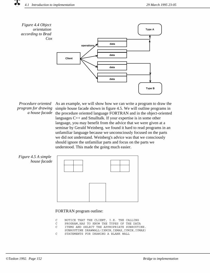
Client
data
data
data
data
Type A
Type B
operations
Figure 4.4 Object orientation
according to Brad Cox
As an example, we will show how we can write a program to draw thesimple house facade shown in figure 4.5. We will outline programs in the procedure oriented language FORTRAN and in the object-orientedlanguages C++ and Smalltalk. If your expertise is in some other language, you may benefit from the advice that we were given at a seminar by Gerald Weinberg. we found it hard to read programs in an unfamiliar language because we unconsciously focused on the parts we did not understand. Weinberg's advice was that we consciously should ignore the unfamiliar parts and focus on the parts we understood. This made the going much easier.
Procedure oriented program for drawing
a house facade
Figure 4.5 A simple house facade
FORTRAN program outline:
C NOTICE THAT THE CLIENT, I.E. THE CALLINGC PROGRAM,HAS TO KNOW THE TYPES OF THE DATAC ITEMS AND SELECT THE APPROPRIATE SUBROUTINE.
SUBROUTINE DRAWWALL(IXMIN,IXMAX,IYMIN,IYMAX)C STATEMENTS FOR DRAWING A BLANK WALL
4.1 Introduction to implementation 29 March 1995 23:05
Bridge to implementation©Taskon 1992. Page 152

C CODE OMITTED END
C SUBROUTINE DRAWWINDOW (IXMIN,IXMAX,IYMIN,IYMAX)
C STATEMENTS FOR DRAWING A WINDOWC CODE OMITTED
END C
SUBROUTINE DRAWDOOR (IXMIN,IXMAX,IYMIN,IYMAX)C STATEMENTS FOR DRAWING A DOOR ...
END C DECLARE ARRAYS KIND, X0, XM, Y0, YM, C AND FILL THEM WITH DATA. CODE OMITTED
DO 1000, I=1 TO MAX IF KIND(I).EQ.1 CALL DRAWWALL(X0(I),XM(I),Y0(I),YM(I)) IF KIND(I).EQ.2 CALL DRAWWINDOW(X0(I),XM(I),Y0(I),YM(I)) IF KIND(I).EQ.3 CALL DRAWDOOR(X0(I),XM(I),Y0(I),YM(I))
1000 CONTINUE
A C++ program for drawing a facade is given below. The knowledge about how to draw a particular element has been delegated to the element itself. This polymorphism simplifies program extension and facilitates reuse.
class Figure {public: virtual ~Figure() {}; virtual void draw() const = 0;protected: Figure(const Point& topLeft, const Point& bottomRight);private: Figure(const Figure&); // Avoid copy Figure& operator=(const Figure&); // Avoid assignment Point topLeftPoint; Point bottomRightPoint;};Figure::Figure(const Point& topLeft, const Point& bottomRight) : topLeftPoint(topLeft), bottomRightPoint(bottomRight){}class Wall : public Figure {public: Wall(const Point& topLeft, const Point& bottomRight); virtual void draw() const;};Wall::Wall(const Point& topLeft, const Point& bottomRight) : Figure(topLeft, bottomRight){}void Wall::draw() const{ ...}class Window : public Figure {public: Window(const Point& topLeft, const Point& bottomRight); virtual void draw() const;};Window::Window(const Point& topLeft, const Point& bottomRight) : Figure(topLeft, bottomRight){}void Window::draw() const{
4.1 Introduction to implementation29 March 1995 23:05
©Taskon 1992. Page 153Bridge to implementation

...}class Door : public Figure {public: Door(const Point& topLeft, const Point& bottomRight); virtual void draw() const;};Door::Door(const Point& topLeft, const Point& bottomRight) : Figure(topLeft, bottomRight){}void Door::draw() const{ ...}class Facade {public: Facade() {} void draw(); void add(Figure* f);private: List<Figure*> list;};void Facade::add(Figure* f){ list.append(f); }void Facade::draw(){
for(ListIter<Figure*> it(list); it.isMore(); it.next()) it.item()->draw();
}
A Smalltalk program for drawing facade is shown below. The syntax is different, but the logic is roughly the same as in the C++ example.
Object subclass: #Figure instanceVariableNames: 'topLeftPoint lowerRightPoint '.
Figure methodsFor: displayingdraw
self subclassResponsibility.Figure subclass: #Window
instanceVariableNames: ''.Window methodsFor: displayingdraw
" Define method for drawing a window. " ...
Figure subclass: #Door instanceVariableNames: ''.
Door methodsFor: displayingdraw
" Define method for drawing a door. " ...
Figure subclass: #Wall instanceVariableNames: ''
Wall methodsFor: displayingdraw
" Define method for drawing a wall. " ...
Figure class methodsFor: testingdrawFacade
| elements | elements := OrderedCollection new. " Add elements and set their attributes. " ... elements do: [:elem | elem draw].
" Evaluate the statement Figure drawFacade to test the program. "
29 March 1995 23:054.1 Introduction to implementation
©Taskon 1992. Page 154 Bridge to implementation

A simple class inheritance example4.1.2
In most object-oriented programming languages, all objects sharing the same implementation are said to belong to a common class, and the class defines the program controlling these objects. A class can create new objects, this is called instantiating the class. All objects created by a given class are called the instances of that class.
The object specification defines the attributes, the class defines the instance variables as the designer's choice of internal representation. Some instance variables contain pointers to the object's collaborators;other instance variables represent its attributes. The class also defines a method for each message that the object must understand. The method is the code describing the actions to be taken by the object when it receives the corresponding message.
Classes, base classesand derived classes
A class may be defined as being similar to another class with given modifications and extensions. This is called programming by difference, and the class is said to be derived from its base class or to be a subclass of its superclass. The derived class will inherit all instance variables and methods from the base class. In addition, it may:
1. add instance variables to the object,
2. add new methods making the object understand additional messages,
override methods in the base class so that the object's behavior is modified for the corresponding messages.
3.
Example: Modeling a point
As an example, we will define a class for objects representing points in a two-dimensional coordinate system. The point object should know its coordinates in both the Cartesian and the polar coordinate systems, so we give it four attributes: x, y, radius (R), and angle (T fortheta). We define messages to set and read these attributes:
SetXY. Set the point's coordinates to the given x and y values.1.
SetRT. Set the point's radius and angle to the given values.2.
3. GetX, GetY, GetR, GetT. Four messages that return the current values of the point's attributes.
We can also define operations on points. For example, the function
4.1 Introduction to implementation29 March 1995 23:05
©Taskon 1992. Page 155Bridge to implementation

vectorAdd returns a new Point, which is the vector sum of the receiving object and the point given as a parameter.
We now have to decide which instance variables to define to hold the attribute information. Should we store the Cartesian coordinates, the polar coordinates or both? All three solutions are possible, the best choice will depend on how we expect the point objects to be used. Wecould store the full, redundant information if we frequently need all the attributes and rarely set their values, otherwise we could store the information in its most frequently used form. The most interesting solution would be to define two classes, CartesianPoint and PolarPoint. Instances of these classes could be used interchangeably, and they could even be mixed. Objects referring to the point objects would onlysee a difference in performance.
The Point class We first define Point as an abstract class, which is a class that should not be instantiated:
class Point {public: virtual ~Point() {};
virtual void setXY(double, double) = 0; virtual double getX() const = 0; virtual double getY() const = 0;
virtual void setRadiusAndAngle(double, double) = 0; virtual double getRadius() const = 0; virtual double getAngle() const = 0;
virtual Point& vectorAdd(const Point& delta) = 0;
protected: Point() {}; // Abstract class
private: Point(const Point&); // Avoid copy Point& operator=(const Point&); // Avoid assignment};
Define abstract class Point in Smalltalk:
Object subclass: #Point instanceVariableNames: ''
Point methodsFor: accessingsetX: x setY: y
self subclassResponsibilitygetX
self subclassResponsibilitygetY
self subclassResponsibilitysetR: rVal setAngle: angVal
self subclassResponsibilitygetR
self subclassResponsibility
29 March 1995 23:054.1 Introduction to implementation
Bridge to implementation©Taskon 1992. Page 156

getTself subclassResponsibility
vectorAdd: aPoint^self class new
setX: self x + aPoint x setY: self y + aPoint y
The ^-symbol in the Smalltalk vectorAdd:-method causes it to return the expression as its function value. The expression is read as follows:Create a new instance of the same class as the receiver. Send the message setX:setY: with parameters (the receiver's x attribute + the parameter point's x attribute) and (the receiver's y attribute + the parameter point's y attribute). Finally, return the value of the expression to the sender.
The CartesianPoint class
We next define a subclass, CartesianPoint, holding Cartesian coordinates. The methods involving x and y are simple, while the methods involving polar coordinates involve computations:
class CartesianPoint : public Point {public: CartesianPoint(double x, double y); ~CartesianPoint() {} void setXY(double nx, double ny); double getX() const { return x; } double getY() const { return y; } void setRadiusAndAngle(double r, double a); double getRadius() const; double getAngle() const;Point& vectorAdd(const Point& delta);private: double x; double y;};CartesianPoint::CartesianPoint(double nx, double ny) : x(nx), y(ny){}void CartesianPoint::setXY(double nx, double ny){ x = nx; y = ny;}void CartesianPoint::setRadiusAndAngle(double r, double a){ setXY(r * cos(a), r * sin(a)); }double CartesianPoint::getRadius() const{ return hypot(x, y); }double CartesianPoint::getAngle() const{ double t = atan2(y, x); if(t < 0.0) t = 2 * PI + t; return t;}Point& CartesianPoint::vectorAdd(const Point& delta){ x += delta.getX(); y += delta.getY(); return *this;}
Define CartesianPoint in Smalltalk:
4.1 Introduction to implementation29 March 1995 23:05
©Taskon 1992. Page 157Bridge to implementation
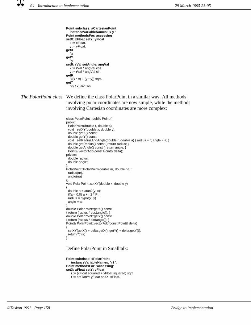
Point subclass: #CartesianPoint instanceVariableNames: 'x y '
Point methodsFor: accessingsetX: xFloat setY: yFloat
x := xFloat. y := yFloat.
getX ^x
getY ^y
setR: rVal setAngle: angVal x := rVal * angVal cos. y := rVal * angVal sin.
getR ^((x * x) + (y * y)) sqrt.
getT ^(y / x) arcTan
The PolarPoint class We define the class PolarPoint in a similar way. All methods involving polar coordinates are now simple, while the methods involving Cartesian coordinates are more complex:
class PolarPoint : public Point {public: PolarPoint(double r, double a) ; void setXY(double x, double y); double getX() const; double getY() const; void setRadiusAndAngle(double r, double a) { radius = r; angle = a; } double getRadius() const { return radius; } double getAngle() const { return angle; } Point& vectorAdd(const Point& delta);private: double radius; double angle;};PolarPoint::PolarPoint(double nr, double na) : radius(nr), angle(na){}void PolarPoint::setXY(double x, double y){ double a = atan2(y, x); if(a < 0.0) a += 2 * PI; radius = hypot(x, y) angle = a;}double PolarPoint::getX() const{ return (radius * cos(angle)); }double PolarPoint::getY() const{ return (radius * sin(angle)); }Point& PolarPoint::vectorAdd(const Point& delta){ setXY(getX() + delta.getX(), getY() + delta.getY()); return *this;}
Define PolarPoint in Smalltalk:
Point subclass: #PolarPointinstanceVariableNames: 'r t '.
Point methodsFor: 'accessing'setX: xFloat setY: yFloat
r := (xFloat squared + yFloat squared) sqrt.t := arcTanY: yFloat andX: xFloat.
29 March 1995 23:054.1 Introduction to implementation
Bridge to implementation©Taskon 1992. Page 158

getX^t cos * r.
getY^t sin * r.
setR: rVal setAngle: angValr := rVal.t := angVal.
getR^r.
getAng^t.
These simple examples illustrate some of the illustrious points about object-oriented programming:
The power of object-oriented
programming
encapsulation. Objects hide their implementation. It is not possible to observe from outside the object how its attributes are represented or how the messages it receives are handled in their methods.
1.
2. configurability. All objects that behave properly towards a given collaborator with respect to messages sent and received, may replace each other with respect to that collaborator irrespective of their class. This property follows from the encapsulation property.
3. polymorphism. Different objects may treat the same message in different ways depending on the methods they use to process it.
4. inheritance. A class can be derived from another class, the derived class only need specify what is different from the base class.
Why we need high level descriptions4.1.3
Why should we ever want to create higher level models of an object-oriented program? The binary executable code is the only representation that gives a precise definition of what the program will actually do under all possible circumstances. The source code contains the equivalent information -- assuming that the compilers, and loaders do what we expect them to do. But we have also added embellishments that have no effect on program execution: Comments are added and program entities are given names that convey meaning to a human reader, but that have no effect on program execution. Most of us still prefer to study the program in its source code form, even if we are occasionally mislead by improper comments and entitynames.
A program is definedby its executable
code
4.1 Introduction to implementation29 March 1995 23:05
©Taskon 1992. Page 159Bridge to implementation

Office procedures are very similar: the office procedures are defined by the procedure texts and there are no high level descriptions. We will later show that higher level, object-oriented descriptions of officeprocedures give important benefits, but we will now restrict our arguments to computer programs.
The binary executable code mixes all system
functions
While we try to create a program structure which clearly separates different concerns into distinct classes and methods, we still end up with having to satisfy several requirements in the same unit. Consider a method that changes the state of a persistent object. The primary function of this method is to change the state. In addition, it must raisean exception if the specified change is inappropriate. It must update all dependent objects such as visual presentations on the screen. It must ensure that the new state of the object is reflected in its persistentform (e.g., on disk). If the state change is part of a transaction that is canceled, it may have to undo it.
Why should we ever want to create high level models of an object-oriented program? If the code is simple and readable, we need nothingelse. In practice, the program code is not as simple and readable as wecould wish, and we have four excellent reasons for wanting to create higher level models:
Why high level models?
Simplification. We want a simplified description which can be grasped by the limited capacity of our skull. We use such abstract descriptions to reason about the system before diving into the details, and to provide a clear documentation of its overall features.
1.
Evolution. The more details we put into our descriptions, the harder it will be to change them. The original rationale for introducing a design stage in the program life cycle was that it is so much cheaper to change a design description than it is to change a complete program. But this is only true to the extent thatthe design description really is smaller and simpler than the program code.
A viable alternative is to describe the essential aspects as a simplified program. This incremental programming approach is often more productive than a prolonged period of high level (and abstract) analysis and design.
2.
4.1 Introduction to implementation 29 March 1995 23:05
©Taskon 1992. Page 160 Bridge to implementation

Emphasis. The program code is an explicit representation of the program logic, the source code may also exhibit the data structures. Important static and dynamic program properties are specified implicitly, and not always easy to fathom. Many OOramviews explicitly express aspects of the program which are not immediately apparent from the program code.
3.
4. Documentation. (Human-to-human communication.) A successfulprogram will have a long life. Many people will try to understand it in order to fix bugs and modify its functionality, usually under high time pressure. Good documentation help them understand the underlying architecture and constraints, and thus maintain system integrity.
Simple models are easy to change
All four considerations have proven to be important in our practical work. Making changes to an isolated role model is trivial, as is making changes to the details of an isolated method. But due to the ripple effect, changing a role model which depends on other role models is harder. In general we can say that the work involved in making a change depends on the number and nature of its dependent parts, be they state diagrams, method definitions or dependent models. Large systems need another abstraction layer to keep things simple. We advocate a clear, modular architecture for this purpose, and keep low level modules stable while the high level modules are being developed. (FOOTNOTE: We will describe OOram modules in chapter 6.5)
Our experience has also provided counter-examples to these observations. Simple role models are excellent for providing the answers to critical questions, but we may fail to find the most critical questions. Our understanding of the issues may be incomplete, problems we deem to be important evaporate under close scrutiny, and problems we believed to be trivial turn out to be real mind boggles. We therefore need to go the whole way and describe the solution as a program before we can be sure that our original questions were the right ones. In the normal life cycle with a design stage separated from an implementation stage, deficiencies in the design which are discovered during implementation cause costly rework.
Simple models may hide ugly details
Some description methodologies, notably in the field of database systems, follow the '100% rule': The high level description shall include sufficient detail for the automatic generation of the application program. We then regard this description as a program
29 March 1995 23:05 4.1 Introduction to implementation
©Taskon 1992. Page 161Bridge to implementation

and the description language (which may be graphical) as a very high level programming language. The whole argument repeats itself: Can we manage with this program as the sole description of the application, or do we need simplified and more abstract models?
Executable specifications are
simplified programs which combine the
best from both worlds
We often find it convenient to introduce an intermediate stage between design and implementation which we call executable specifications. These specifications are implementations in the sense that they can be executed as programs, but they neither have the efficiency nor the robustness required of a finished program product. Their aim is to highlight deficiencies and details in the system logic, they are abstractions in the sense that they suppress many aspects of the target program and hide trivial details.
Some computer professionals may tend to associate system description paradigms with the internal workings of the computer. Butthe computer hardware does not "know" about Fortran and C, entities,relations, objects, or messages. A computer is just a piece of electronic hardware, performing its operations according to the programs represented as bit patterns in its memory. So the audience ofa high-level description is a human being, not a computer.
The ultimate consumer of a
manifest model is human
Many years ago, we attended a seminar given by M. A. Jackson whichprofoundly changed our attitude to programming techniques. The following is a description of the result of this experience. (Apologies to Jackson if he should be misrepresented.)
In figure 4.6, the top line symbolizes all programs that a given computer may perform. These programs are generated by systematically loading the computer's memory with each possible bit pattern, and then, in turn, ask the computer to start executing from each possible starting point. The number of different programs that can be executed by our own personal computer is on the order of 10 raised to the power of many million, a truly staggering figure. Most ofthese programs will come to an abrupt halt; some of them will never terminate. To the computer, they are all legal programs. What most of them have in common is that they do nothing that we, as humans, regard as useful or even meaningful.
We only permit systems we understand
The middle line in the figure illustrates the almost infinitesimal subsetof these programs that do something that we find meaningful. Jackson's insight was that even these programs are not acceptable, because the functioning of most of them will be outside the grasp of the human mind. Jackson's thesis was that of all the meaningful
29 March 1995 23:054.1 Introduction to implementation
©Taskon 1992. Page 162 Bridge to implementation

programs, we should limit ourselves to the small portion of them that we can understand. This is illustrated as the bottom line of the figure.
Jackson: "For any given problem, there is one and only one correct solution. The tragedy of computing is that there are so many other solutions which also work."
Figure 4.6 Our methodologies are
designed for people -- computers will accept anything
The set of all possible programs is extremely large
The set of all meaningful programs
The set of all understandable programs
Simplicity is a goal Our first line of defense is to create programs that are within the graspof the human mind; programs that are "so simple that there are obviously no deficiencies". We believe that such programs should be our ideal. No other representation can beat the simple program text for precision, clarity and completeness.
The need for high level representations arise when the problem is too complex to yield simple code in its solution -- when the structure of objects gets too large to be readily grasped by the human mind. OOram role modeling was created to answer this need and to provide a model of the program that is simple and easy to understand.
4.1 Introduction to implementation29 March 1995 23:05
Bridge to implementation ©Taskon 1992. Page 163

The relationship between a role model and its implementation
4.2
In a nutshellThe OOram role model describes the static and dynamic properties of a pattern of collaborating objects. The program classes specify the exact static and dynamic properties of their instances. Both descriptions define the objects, and there is a clearrelationship between them. We will see that it is easy to transform the information inthe role model into corresponding information in the classes.
An OOram role model can be promoted to an object specification model, where the roles are promoted to object specifications. The object specification roles are shown in heavy outline as illustrated in figure 4.7. A virtual role has to be resolved into concrete roles before being promoted, since a virtual role represents a cluster of objects rather than a single object.
Any role model can be implemented
Figure 4.7 Roles specifying
implementation are shown with heavy
outline
System role Environment role
System objectspecificationto be implementedas a class
Environment objectspecification is sometimesimplemented asan incomplete class
OOram concepts mapped on to the
programming language
Role models specify the static and dynamic properties of object patterns, and thus object-oriented programs. The concepts of the role models map on to the concepts of the programming language. We indicated possible mappings in the Main Ideas, and repeat it in table 4.1 for your convenience. The map is meant to help a programmer understand the OOram terms; but the terms are not equivalent since the OOram method focuses on roles and a programming language focuses on classes.
29 March 1995 23:054.2 The relationship between a role model and its implementation
©Taskon 1992. Page 164 Bridge to implementation

Table 4.1 Mapping OOram models to
programs
OOram Smalltalk C++
Role Model -- --
Role Object Object
Object Specification, Type Class Class
Port Variable Pointer data member
Interface Protocol Abstract class or protocol class
Message Message Function call
Method, Action Method Member function
Derived model Subclass Derived class
Base model Superclass Base class
Implementing the roles4.2.1
A role is an idealized description of an object in the context of a pattern of collaborating objects. Through our policy of divide and conquer, we focus on the object aspects that are relevant for the role model's area of concern.
An object specification is a
partial description ofan implemented
object
The object specification describes an object which will actually be implemented. The role is made more concrete when we promote it to an object specification. The programming language concept corresponding to an object specification is a class.
The default is that there is a one-to-one relationship between object specification and class, but in general there is a many-to-many relationship between them.
The simplest situation is if we create a complete object specification model for the set of classes we want to implement. In figure 2.17 on page 78??, we defined a Client-Server model and a Data transfer model. In figure 3.18 on page 121??, we used these models as base models and derived a File send/receive model. In figure 4.8, this model has been promoted to an object specification model ready for implementation in two classes, one for each role.
src intSend/receiveClient
Send/receiveServer
Figure 4.8 File send/receive object specification model
29 March 1995 23:05 4.2 The relationship between a role model and its implementation
©Taskon 1992. Page 165Bridge to implementation
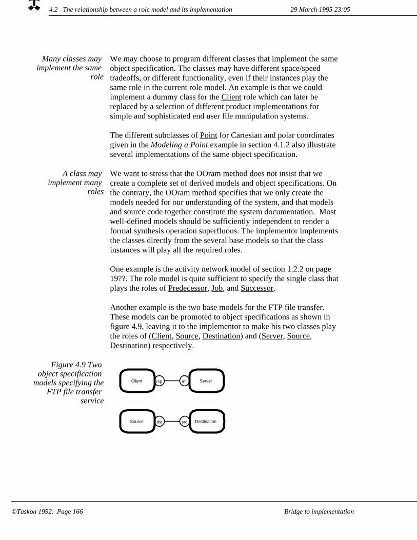
Many classes may implement the same
role
We may choose to program different classes that implement the same object specification. The classes may have different space/speed tradeoffs, or different functionality, even if their instances play the same role in the current role model. An example is that we could implement a dummy class for the Client role which can later be replaced by a selection of different product implementations for simple and sophisticated end user file manipulation systems.
The different subclasses of Point for Cartesian and polar coordinates given in the Modeling a Point example in section 4.1.2 also illustrate several implementations of the same object specification.
We want to stress that the OOram method does not insist that we create a complete set of derived models and object specifications. On the contrary, the OOram method specifies that we only create the models needed for our understanding of the system, and that models and source code together constitute the system documentation. Most well-defined models should be sufficiently independent to render a formal synthesis operation superfluous. The implementor implements the classes directly from the several base models so that the class instances will play all the required roles.
One example is the activity network model of section 1.2.2 on page 19??. The role model is quite sufficient to specify the single class that plays the roles of Predecessor, Job, and Successor.
A class may implement many
roles
Another example is the two base models for the FTP file transfer. These models can be promoted to object specifications as shown in figure 4.9, leaving it to the implementor to make his two classes play the roles of (Client, Source, Destination) and (Server, Source, Destination) respectively.
dst src
rsp intClient Server
Source Destination
Figure 4.9 Two object specification
models specifying theFTP file transfer
service
29 March 1995 23:054.2 The relationship between a role model and its implementation
Bridge to implementation©Taskon 1992. Page 166

Our naming convention is that role names are alphabetic, and classes are given the names of the primary role followed by a numeric suffix. The class for the Client role could be named Client1, and the class for the Server role could be Server1. We thus follow the naming conventions for classes in our programming language when we name our roles.
We name classes with numeric suffix
The object specifications of figure 4.8 and 4.9 both lead to the following class definitions:
// Class: SendReceiveClient1class SendReceiveServer1;class SendReceiveClient1 {public: SendReceiveClient1(); ~SendReceiveClient1();private: SendReceiveClient1(const SendReceiveClient1&); // Avoid copy SendReceiveClient1& operator = (const SendReceiveClient1&); // Avoid assignment SendReceiveServer1* server;}; // end of SendReceiveClient1// Class: SendReceiveServer1class SendReceiveServer1 {public: SendReceiveServer1(); ~SendReceiveServer1();private: SendReceiveServer1(const SendReceiveServer1&); // Avoid copy SendReceiveServer1& operator=(const SendReceiveServer1&); // Avoid assignment SendReceiveClient1* client;}; // end of SendReceiveServer1
Similarly in Smalltalk:
Object subclass: #SendReceiveClient1instanceVariableNames: 'server '.
Object subclass: #SendReceiveServer1instanceVariableNames: 'client '.
A class may be derived from a base class, and a group of classes may be derived from a group of base classes.
An object specification model can be derived from a base object specification model. This is an open invitation to let the derived classes be derived from the corresponding base classes. We could, for example, define base classes for the Client and Server roles and augment them with send/receive functionality in the subclasses. In Smalltalk:
Synthesis can be mapped on to class
inheritance
Object subclass: #Client2instanceVariableNames: 'server '.
Object subclass: #Server2instanceVariableNames: 'client '.
Client2 subclass: #SendReceiveClient2instanceVariableNames: ''.
Server2 subclass: #SendReceiveServer2instanceVariableNames: ''.
29 March 1995 23:05 4.2 The relationship between a role model and its implementation
Bridge to implementation ©Taskon 1992. Page 167

If our programming language includes facilities for multiple inheritance, we could implement classes for the Client, the Server, theSource and the Destination roles. We could then implement the different combinations described in figures 3.16 through 3.18 by suitable derivations. An example for the file send/receive case is shown in figure 4.10.
Figure 4.10 Possible multiple inheritance
hierarchy
Destination2
SendReceiveServer2SendReceiveClient2
Source2Server2Client2
The following C++ code uses multiple inheritance to implement the class structure of figure 4.10. You may find that it is more interesting than it is practicable:
// Class: Client2class Client2 {public: Client2(); ~Client2();private: Client2(const Client2&); // Avoid copy Client2& operator=(const Client2&); // Avoid assignment}; // end of Client2// Class: Source2class Source2 {public: Source2(); ~Source2();private: Source2(const Source2&); // Avoid copy Source2& operator=(const Source2&); // Avoid assignment}; // end of Source2// Class: Destinationclass Destination {public: Destination(); ~Destination();private: Destination(const Destination&); // Avoid copy Destination& operator=(const Destination&); // Avoid assignment}; // end of Destination// Class: Serverclass Server {public: Server(); ~Server();private: Server(const Server&); // Avoid copy Server& operator=(const Server&); // Avoid assignment}; // end of Server// Class: SendReceiveClient2class SendReceiveServer2;class SendReceiveClient2 : public Client2, public Source2, public Destination {
4.2 The relationship between a role model and its implementation 29 March 1995 23:05
Bridge to implementation©Taskon 1992. Page 168

public: SendReceiveClient2(); ~SendReceiveClient2();private: SendReceiveServer2* client;}; // end of SendReceiveClient2// Class: SendReceiveServer2class SendReceiveServer2 : public Server, public Destination, public Source2 {public: SendReceiveServer2(); ~SendReceiveServer2();private: SendReceiveClient2* client;}; // end of SendReceiveServer2
When we use automatic program generators, we find it convenient to distinguish between the automatically generated code and the manual extensions. We let the tools create (abstract) classes with a zero suffix, e.g., Client0, and the programmer extends and modifies this code in a subclass, e.g., Client1. The advantage is that we can regenerate the superclass when the models are modified without interfering with the manually prepared code. The disadvantage is the added complexity caused by doubling the number of layers in the class structure, see figure 4.11.
Automatic code generators useful,
but less flexible than human programmers
Client0automatically generated
abstract (base) class
Client1manually codedconcrete class
Inheritance
This class may beupdated automaticallyat any time ...
... without destroying themanually created codein this class.
Figure 4.11 Automatically
generated superclasses,
manually prepared subclasses
We have been using automatic code generators for Smalltalk and Eiffel, and find them very useful for creating executable specifications and prototypes. We usually remove the abstract layer from the final production code to avoid the unnecessarily deep class hierarchy, and use checking programs to maintain the correspondencebetween object specification and code in the maintenance phase.
29 March 1995 23:05 4.2 The relationship between a role model and its implementation
Bridge to implementation ©Taskon 1992. Page 169

Implementing the ports and interfaces4.2.2
A port describes a variable
A Port is an abstraction of a variable. The default is to map the port toan instance variable, but it may be mapped into any kind of variable. In Smalltalk, it could be a global, instance, class, or temporary variable; in C++ it could be private or public.
A multi-port is implemented with a
collection
The implementation of a port will depend on its cardinality. A ONE-port will be represented as a pointer variable. A MANY port will be represented as some kind of collection such as Set, Array or LinkedList. The role model does not formally specify the kind of collection to be used. The choice is left to the implementor, but the analyst can indicate his preference in a comment associated with the port.
The default name of the variable is the name of the port. We usually follow the naming conventions for variables in our programming language when we name our ports.
The port is not necessarily implemented as an instance variable; because a local method could compute the pointer whenever needed. The message interaction between collaborators could also be taken care of by a special program. In the case of the FTP file transfer implementation, the messages will be transmitted through a communication path according to the Internet Transmission Control Protocol (TCP). The operating system is likely to support some kind of socket that facilitates this communication, and our methods will usethese facilities to transmit messages.
Such program details are immaterial for the role models at the analysis level. They can be described in design level role models or they can be left to the discretion of the implementor.
The important principle is that while a role model may give a simplified view of the program, it should be given a true representation of the collaboration structure in the context of its area of concern. There must be a port for every message sent, you cannot say that a particular port is unimportant because it only lasts for a few microseconds. We either need it, and then it should be shown. Or we do not need it, and then we should not send messages along it.
If we find that the collaboration view gets too complicated when we show all the relevant interaction paths; we must simplify the program logic rather than cheat ourself and others by falsifying the view.
The role model should never lie
29 March 1995 23:054.2 The relationship between a role model and its implementation
Bridge to implementation©Taskon 1992. Page 170

An OOram interface is a named collection of messages that may be sent from one role to another. The popular programming languages such as Smalltalk and C++ define all messages that are to be understood by the instances of a class; they do not check that the messages originate from an authorized sender. The reason for the mismatch is that we in OOram focus on patterns of collaborating objects, while the popular languages focus on the capabilities of individual classes.
OOram controls the messages sent
This apparent mismatch is easily bridged: The messages to be understood by a class is the union of all the messages sent to it from its collaborators. If we implement role B in figure 4.12 as class B1, we give it two variables ba and bc and create methods for all the messages sent from its collaborators as indicated in the figure. We similarly create classes A1 and C1 which implement roles A and C respectively. Class A1 will define a variable ab and methods which send messages messAB1 and messAB2 to this variable. Class C1 will define a variable cb and methods which send messages messCB1 and messCB2 to this variable.
ab ba
bc
cb
ac
ca
A
B<CmessCB1messCB2
B<AmessAB1messAB2
B
C
A class implementing role Bmust implement methods forall received messages: Interface B<A messAB1 messAB2 Interface B<C messCB1 messCB2
Figure 4.12 A rudimentary object
specification example
4.2 The relationship between a role model and its implementation29 March 1995 23:05
Bridge to implementation ©Taskon 1992. Page 171

It would be nice if the compiler could check that our implementation actually conforms to the object specification.
In Smalltalk, we can implement the named interfaces as Smalltalk protocols. A Smalltalk compiler does not enforce the OOram specifications since it does not support static type checking. The type system of statically typed languages does not readily support our notion of giving different message privileges to different collaborators, see box. Neither Smalltalk nor C++ guarantee that a value has been assigned to a variable before it is used. (Some Smalltalk compilers do a partial check.)
Once we know the classes that implement given roles, it is easy to check that they understand all the messages they are supposed to receive. It is harder to check that objects will only send the messages they are supposed to send. We can rely on manual checking, which is error prone and tedious; static code checking programs, which are hard to make; or monitored execution programs for dynamic testing, which can only test specific cases. Monitored execution will be described in chapter 6.5 on page 238??.
Checking implementation
conformance
BOX: An unsuccessful attempt at supporting OOram specifications with language type systemA fine point for the specially interested: When developing a bridge between OOram object specifications and the Eiffel programming language, we tried to define deferred Eiffel classes for the ports. Classes ab and cb define the respective interfaces, and class B1 was made a subclass of these classes so that it supported both interfaces. The advantage was that the compiler checked the interfaces against the OOram object specification. The disadvantage was that we got a very large number of classes and spent much time in compilation.
The scheme was torpedoed by its handling of object references in message parameters, however. Consider the role model in figure 4.12. Assume that the computation process starts with anA1 (an instance of A1) creating aB1, storing a pointer to this object in its variable ab. It then creates aC1, and sends a message setB with aB1 as parameter to aC1. The variable ab in aB1 is typed with the ab interface. The object aC1 receives the setB message and tries to store the parameter in its cb variable. But cb is typed differently from ab, and we get a type error. Changing the type of variable cb does not help, because the object aC1 then cannot send the required messages to aB1.
This experiment confirmed Bjarne Stroustrup's assertion mentioned earlier: If you don't like the basic type system of a language, use another with a type system that suits your taste better.
4.2 The relationship between a role model and its implementation 29 March 1995 23:05
©Taskon 1992. Page 172 Bridge to implementation

Implementing the methods and actions4.2.3
A method specifies the work to be done by an object when it receives a message. Methods (or member functions) are defined explicitly by their code in the class; message sends appear embedded in the code. OOram role models can include method specifications that can be defined on four different levels of detail:
OOram supports different levels of
method detail
By the name of the message and a comment describing its intention. The programmer has to create the code from his generalunderstanding of the designer's intentions.
1.
By a free text (comment) describing the method's operation together with a specification of the messages sent from the method and their receivers.
2.
3. By pseudocode describing the method's operation together with aspecification of the messages sent from the method and their receivers.
4. As code in a programming language such as C++ or Smalltalk.
The first level is an integral part of the message interface view, and the remaining levels are seen in the Method specification view described in section 2.5.2 on page 102?? Figure 2.38 on page 104?? isan example of a method specified as pseudocode.
Depending on the details included in the method specifications, automatically generated methods can be more or less complete. In the simplest case, the method (procedure) header may be generated automatically together with the message explanation in the form of a comment. Formal parameters and their type will be included, if this information is in the role model. The method bodies will be generatedas completely as possible from the specifications.
Automatic code generation
4.2 The relationship between a role model and its implementation29 March 1995 23:05
©Taskon 1992. Page 173Bridge to implementation

The implementation process4.3
In a nutshellThe yo-yo approach to computer programming is an opportunistic, risk-reducing strategy. As usual, we do not believe in snake oil, and recommend that you develop your own implementation process that is uniquely adapted to you own requirements.
Your implementation processes must be
tailored to your needs
Like all other work processes, you will have to tailor your implementation processes to your specific applications and your own work situation. Your previous experience with systems development in general and object-oriented development in particular, is of crucial importance, as are the facilities available to you and the kinds of systems you want to develop. This section may give you a useful starting point if you are relatively new to object orientation.
The OOram perspectives and views are designed to support a wide variety of work processes and implementation styles. The large variety of perspectives and views support many different abstractions, and the freedom to choose the detailed syntax and message semantics support different programming styles.
OOram supports many different work
processes
The idea of top-down development was introduced in the sixties. [Oxford 86] gives the following description: "An approach to program development in which progress is made by defining required elements in terms of more basic elements,..." The trouble with the top-down approach is that the devil is often found in the details: the early assumptions prove to be inadequate and the top-level design has to be modified.
Top-down approach powerful, but the
devil may be in the details
The pure top-down approach seemed very rational, and we advocated it in several seminars and university courses in the seventies. We also asked a number of graduate students to use the approach in their work and to report on their experiences. Much to our chagrin, we found thatnone of the students were able to follow our sound advice. We then monitored our own work, and found that we regularly broke the rules ourselves. Further observation told us that a prerequisite to following the top-down approach was that we knew at least one and preferably several ways of implementing the lower level details. This was rarely true for the students with their limited experience, and often not true for us when we were exploring new application technologies.
We find the same problems when we teach object orientation and the
4.3 The implementation process 29 March 1995 23:05
©Taskon 1992. Page 174 Bridge to implementation

OOram method to programmers. It is hard to relate to abstract concepts, and the only way to make them real is to actually write concrete, object-oriented programs. We advise a concrete-to-abstract approach to learning object orientation: begin by writing simple programs, and only introduce the OOram method when the basic concepts are well understood through real programming experience.
Bottom-up approach:The parts may not fit
together
An alternative is the bottom-up approach, which [Oxford 86] describes as follows: "An approach to program development in which progress is made by composition of available elements ..." The trouble with the bottom-up approach often appears in the final system integration stage. The system components may be excellent in themselves, but this does not guarantee that they can be composed into the required system.
Our current approach is what we call the yo-yo approach, which is a combination of the top-down and bottom-up approaches according to the principle of minimizing risk. We identify the part of the problem that we consider will be the hardest to get right, and experiment with possible solutions. When we feel that we have mastered this part, we identify the next part which we consider will be the hardest, and so on. This principle of minimizing risk corresponds in many ways to theprinciples advocated in [Boehm 88], where you will find many more details.
An alternative to the principle of minimizing risk is to solve the simple problems first so as to get early tangible results. This is often good for morale and may even help clarify the hard problems by removing extraneous details.
The principle of minimizing risk
The nature of the critical part will vary from case to case. We may notknow which functionality the users will actually need. It is then a good idea to start with the user interfaces, and support them with dummy data representations. The users get hands-on experience with the proposed system at a very early stage and can provide valuable feedback.
Identify critical uncertainty
In other cases, we may suspect that we do not understand the users' mental models. It can then be appropriate to start with a collaboration view, possibly making it appear concrete to the users by providing appropriate user interfaces.
The critical problems could also be on a low level. Will we really be able to create the algorithm for a required function, or do we need
4.3 The implementation process29 March 1995 23:05
Bridge to implementation ©Taskon 1992. Page 175

magic to solve the problem? Can we create a program that satisfies the speed requirements? Practical experiments can give the answer.
The yo-yo approach implies that we want to be able to cross a bridge between OOram models and implementation in both directions: we may have created a design and want to implement it, or we may have created a prototype implementation and want to extract the design information from it. Good processes with their associated tools shouldsupport both directions.
Cross the implementation
bridge in both directions
We are programmers at heart, and we rarely find that we fail to notice woolly details. The danger is rather that we keep too narrow a scope for our work. We guard against system integration problems by creating the top level program as early as possible -- inserting dummy methods for the details. We then fill in programs for the critical parts as they are created. In this way, we have an operational program from a very early stage which we keep improving until it is ready for delivery. Whenever possible, end users are involved in the prototype testing, so that they can get maximal influence on the final product.
Keep an eye on the total problem!
We are constantly trying to be conscious of our own mental blocks. We may, for example, work on the high level aspects of a distributed system, and find that our thoughts keep wandering off to the problem of program-to-program communication. We then digress and work with a small distributed program until we have removed the block. Once the problem is cleared, we can continue the high level considerations and base them on a solid foundation.
Beware of mental blocks!
There is one caveat to the principle of minimizing risk: Most development projects have a deadline on time and resources. It is indeed a sad situation if essential functionality is still missing when the ax falls and the project has to be terminated.
Identify essential functionality!
There are great benefits to be gained if we manage to stimulate the creativity of the users and everybody else around us: it improves the final product and its acceptance; it is stimulating; and it is great fun. But beware of escalating specifications! Some functionality may have to be postponed to a later project, or the scope of the current project may have to be expanded to take the users' increased appetite into account.
Beware of escalatingspecifications!
4.3 The implementation process 29 March 1995 23:05
Bridge to implementation©Taskon 1992. Page 176

As a general rule, we do not cross bridges until we get to them. We tryto make the system architecture expandable, and we regard the users' expressed requirements as examples rather than the whole story. But we keep the code consistent with the architecture and as simple as possible. We do not complicate it to provide hooks for extensions. The following guidelines are inspired by the excellent book by Kernighan and Plauger [KerPla 74] on programming style, which should be required reading for all programmers. The guidelines not only apply to programming, but to all levels of analysis and design:
Postpone program optimization!
Make it right. Our first concern is to create a program that reflectsthe user requirements.
1.
Make it clear. Our second concern is to make the program simple -- "so simple that there are obviously no deficiencies". The first program versions are often dirty: The division of responsibility between the objects is not optimal; the same logic is repeated in several locations and can be replaced by a single occurrence in the right location. We use reverse engineering to extract the design from a running program. We then clean up the design before re-implementing a cleaner version of the program.
2.
Make it fail-safe. The encapsulation property makes it fairly easy to protect objects from all kinds of abuse from their collaborators.If we take this principle too far, we end up with schizophrenic objects that spend most of their time checking each other. It is a good idea to draw boundaries around groups of objects; we call them fire walls. We carefully check all messages passing a boundary and trust all messages flowing within it. The role modelis a convenient unit for fire wall protection. All stimulus messages are treated with suspicion, while all internal interactionsare assumed to be in order.
3.
Instrument the programs. Measure before making "efficiency" changes. There is no point in optimizing code that has but a smallcontribution to the overall running time of the program. We find that our intuition about where the program spends its time is unreliable. We postpone making efficiency changes until the program execution time proves to be a problem, and then only after careful and detailed performance measurements. (This applies to code details. It is usually more important to design an efficient architecture than to optimize the code.)
4.
4.3 The implementation process29 March 1995 23:05
©Taskon 1992. Page 177Bridge to implementation

To sum up, the development process can start with a prototype implementation or with an abstract analysis. In either case, the process is iterative, moving between the abstract and the concrete until the system is complete (or until the available time and budget have been exhausted.)
The iterative development process
Figure 4.13 Simple implementation
processOOram role modeling
OOram Object Specification
Implementation
(1) Make it right(2) Make it clear(3) Make it fast
Reverse engineering
Forward engineering
Start herefor formal analysis and design
Start herefor quick early results
Testing
Prototyping,Exploratory programming
Forward engineering
Notice the bottom loop in the above process. Modern programming environments with source code browsers and incremental compilation makes exploratory programming really attractive, because we can express our ideas directly in programming language and test them immediately. Exploratory programming is particularly powerful for the Make it right-phase. In one session where we monitored our work,we created a first prototype in just under three hours. The measured average cycle time (think-edit-compile-test) was 2.5 minutes.
Exploratory programming is
powerful
Create your own process!
We do not expect that this process is quite right for you, but it may give you ideas that could be useful when you create your own process.You will also want to add further steps for product implementation, testing, installation and maintenance. Do not expect your first process to be the ideal one, but observe how you actually work and improve the process description as you gain experience.
4.3 The implementation process 29 March 1995 23:05
Bridge to implementation©Taskon 1992. Page 178

Exploratory programming may
play havoc with software reliability
Back in 1980, our group at the SINTEF-SI research institute had logged twenty years of FORTRAN software product development andconsidered itself pretty professional. We followed a waterfall life cycle model and used techniques such as careful design and peer reviews to produce reliable code. We believed, as we still believe, in Dijkstra's dictum that the only way to produce software without errorsis to avoid introducing them in the first place; the number of errors remaining in the programs is likely to be proportional to the number of errors found and removed during testing. In one monitored case we did in 1976, we found no errors in two out of three subroutines during unit testing, and no errors at all during system testing. (It was a 2,000 line preprocessor for object based FORTRAN programming.)
Exploratory programming seems to be the antithesis to this careful approach to software development. While the group immediately recognized its clear benefits, there was strong opposition to introducing such a haphazard technique into our tidy development process. The solution we have ended up with is the double loop approach shown in figure 4.13 where exploratory programming is considered a specification activity. The final program is created top down according to the established principles.
Our message to users and management is that a nice looking prototype or demonstration program can be created in no time, but it takes real time to create a real program. An early prototype looks good to users and management, and it is sometimes hard to persuade them that the main part of the work remains to be done. We are still searching for software metrics which can make this main part visible, so that it will be properly appreciated by managers and clients. (This section is written for programmers, but you may want to show this paragraph to your manager!)
Development of real software takes real
time
System development is teamwork
Significant systems are developed by groups of people working together in teams. In the middle ages they had polymaths, geniuses who knew everything that was worth knowing. Geniuses have always been in short supply, and the current body of knowledge is too large to be mastered by a single person. But a balanced team can possess a polymathic knowledge within the team's area of responsibility, and the symbiotic intelligence of a closely cooperating team can exhibit many of the characteristics commonly associated with a genius.
29 March 1995 23:05 4.3 The implementation process
©Taskon 1992. Page 179Bridge to implementation

Our view on the ideal system development team has been strongly influenced by Gerald Weinberg's epoch-making book on The Psychology of Computer Programming [Weinb 71]. The success or failure of a team member is closely linked to the success or failure of the team: we all succeed or we all fail. Ruth cannot claim that the project's failure was caused by Stupid Sam; she should have discovered the difficulties and taken corrective action in time. Open communication channels, mutual respect and acceptance of individualstrengths and weaknesses are essential properties of a good team.
Egoless teamwork
A common language is essential for effective communication channels. Object orientation and the OOram method constitute our common language on the abstract level. Our programming rules and conventions provide the language on the concrete level. The intention of our conventions is what Weinberg calls egoless programming: any programmer in the team shall be able to read any piece of code and work with it in an effective manner. There is no such thing as component ownership -- only component responsibility which may bereassigned to other team members. We recommend that you establish your own conventions adapted to your team's requirements.
Common language essential
Process depends on problem
We tend to get suspicious when we meet someone who has the ultimate work process that will work with all kinds of people for all kinds of problems. We find that our optimal work process depends on the kind of problem we are going to solve, its position on a sophistication scale from routine to research, the availability of reusable components which are applicable to the problem, the time available, the number and qualifications of people we are going to work with, and a host of other factors. To us, industrial production of software implies that all these factors are kept reasonably fixed to permit the evolution of an optimal work process.
29 March 1995 23:054.3 The implementation process
©Taskon 1992. Page 180 Bridge to implementation

Choice of programming language4.4
In a nutshellThere is no perfect programming language that is ideal for all purposes. Yet many programmers feel very strongly about their language and are personally affronted if somebody dare propose that another language could be superior for some purpose.
It is therefore with some hesitation we suggest that Smalltalk is a higher level language than C++. We believe that C++ is the better language for many purposes because it gives the programmer complete control of low-level computational details such as memory allocation. We also believe that Smalltalk is better for other purposes because it invites the programmer to ignore low-level computational details such as memory allocation.
Role models are used to model a wide range of phenomena both within computers and in the world around them. The appropriate implementation technologies will depend on the nature of the phenomenon and the purpose of the implementation. The processes used to create the human objects of a travel expense model are very different from the processes used to create the computer-based objectsof an file transfer program. Even if we confine ourselves to the creation of computer-based systems, the ideal implementation processwill depend on the problem and the selected programming language.
Different implementation technologies for
different phenomena
In an ideal world, the implementation would be written in an OOram programming language, which would reflect the concepts of the OOram method. For example, a variable should be typed to ensure that it could point to any object that was capable of playing the specified role or roles regardless of the object's implementation.
We focus on Smalltalk and C++
In the real world, we have to use one of the standard programming languages that have been developed without regard to any specific modeling technology. The final choice of programming language maybe based on technical considerations; on total life-cycle costs; on strategic considerations such as training requirements; or even on apparent popularity.
The main vendors of object-oriented program development systems do not publish their sales statistics, but C++ and Smalltalk seem to be the most popular languages, followed by Eiffel and Objective C. C++ is currently by far the most widely accepted language. Smalltalk seems to be increasingly accepted, particularly in the business information system community.
4.4 Choice of programming language29 March 1995 23:05
Bridge to implementation ©Taskon 1992. Page 181
The hard part of learning object
orientation is to internalize the
mental model, not to learn the language
syntax
There are many C programmers in the world, and many people believe that it is easier for a C programmer to make the transition to object-oriented thinking through C++ than through Smalltalk. We believe this to be a fallacy. The very similarities between C and C++ can make the essential paradigm shift harder because the programmer is permitted to continue thinking along the old track. We believe that it is much better to make a clean break and create the first object-oriented implementations in a pure object-oriented language such as Smalltalk, even if the final products are to be written in a hybrid language such as C++.
Smalltalk may appear more
productive
It is hard to compare the productivity of a Smalltalk programmer relative to a C programmer. A few studies that have been mentioned on the electronic bulletin boards seem to indicate that Smalltalk is six times more productive than C. But the samples used in the studies have been small, and the effects of different people, development processes, and program libraries have not been considered. Smalltalk is a higher level language and should be more productive, but we cannot claim that this is borne out by conclusive observation.
C++ is a statically typed language. Variables are typed on the class of the permissible objects, and the compiler ensures that the object receiving a message will also have a method which can handle it. The programmer can override this discipline with type casting, and can then specify messages which cause catastrophic termination of the program.
The Smalltalk language is untyped in the sense that a variable may point to any object. It is dynamically typed in the sense that all objectswill handle any message in a defined way: if an object does not have amethod for the received message, a Message not understood exceptionis raised and the programmer can decide on the proper action to take in these cases.
Static and dynamic typing
29 March 1995 23:054.4 Choice of programming language
Bridge to implementation©Taskon 1992. Page 182

Typing system beneficial
We have no doubt about the benefits of a typing system. It prevents a certain class of runtime errors and enforces a precise documentation of the variables. We are more doubtful about the wisdom of typing a variable on the implementation (class) of the objects to which it refers,because the implementation descriptions include all details about the internal construction of the object. Typing on implementation thus breaks the object encapsulation, and we lose the valuable flexibility and generality that enable us to create objects with identical external characteristics, but with different implementations.
For example, we have a Smalltalk implementation of a rudimentary relational database; we use it for prototyping and demonstration purposes. A separate set of classes implement clients for remote access to popular database servers. All these database classes implement interchangeable objects, but need not have a common base class.
Our systems evolve over the years, and we sometimes want to replacean old class hierarchy with a new and better one. We want to introduce the new hierarchy gradually as our confidence in the new solution grows and as time permits. Both the old and the new class hierarchies, therefore, have to coexist in the system for a considerable period of time.
While it is possible to use the notions of abstract or virtual classes to fake a type system in the statically typed languages, we would prefer a language with an explicit type system that supported the OOram notion of roles, collaborations, and interface definitions.
Abstract classes are artificial
Garbage collection Some languages such as Smalltalk, Eiffel and Objective C have automatic garbage collection. This means that objects are retained in memory as long as they are reachable from the root of the object structure. When the object is no longer reachable, its memory space is automatically released and can be reused by other objects.
Other languages such as C++ have manual garbage collection. It is theresponsibility of the programmer to know when an object is no longerneeded and to explicitly free its memory space. It is both hard and important to get this memory management right. If object space is not freed, the memory will gradually be filled with garbage. If an object isfreed prematurely, the system will crash catastrophically. We recommend that if the target language does not support automatic garbage collection, the creation and destruction of objects should be clearly described in appropriate role models.
4.4 Choice of programming language29 March 1995 23:05
©Taskon 1992. Page 183Bridge to implementation

All complete programming languages are in some sense equivalent, and any computation may somehow be realized in any language. Languages differ in how directly the programmer's ideas may be expressed. It has been said that a real programmer can write FORTRAN in any language. Bjarne Stroustrup, the inventor of the C++ language once said "C++ is not a very good Smalltalk; it was notmeant to be. Similarly, Smalltalk is not a very good C++; it was not meant to be."
This means that if we use C++, we should adapt to the C++ way of thinking. Similarly, if we use Smalltalk, we should adapt to the Smalltalk way of thinking. One of the goals of the OOram method hasbeen to make its notions adaptable to the different programming stylessupported by the different programming languages, but its actual use should be colored by the philosophy of the target programming language.
Do not violate the intentions of your
programming language
Smalltalk is a higher level language than C++. A number of data representation and memory management issues have been automated and made invisible to the programmer. This, combined with its English-like syntax and uniform use of objects, has empowered us to create user interfaces, system architectures, and reusable programs which would otherwise have been outside our intellectual grasp.
Smalltalk higher level than C++
There is no such thing as a free lunch. Smalltalk has acquired a reputation for being inefficient. There are several reasons for this reputation. One is that Smalltalk pioneered sophisticated user interfaces which consume vast amounts of computer power. Such programs were bound to lose when they were compared to C programs implementing traditional command-line interfaces.
C more efficient thanSmalltalk
Another reason could be that the typical Smalltalk programmer may be more inclined to reuse existing code, even if specialized code couldbe made more efficient.
A third reason is that the high-level, dynamic nature of the Smalltalk language makes it harder to create efficient compilers and runtime systems. When we began using Smalltalk at the end of the seventies, we estimated that a Smalltalk program could be up to 40 times slower than a comparable C program. There has been impressive improvements in compilers and run-time technology since those early days. [Chambers 89] reports a factor 10 between an early Smalltalk and plain C; the current releases of Smalltalk are significantly faster. It is also possible to call low-level, optimized C procedures from a Smalltalk program.
29 March 1995 23:054.4 Choice of programming language
©Taskon 1992. Page 184 Bridge to implementation

Rational choice should be made on total life cycle costs
We believe that a rational (as opposed to strategic) choice of programming language should be made on the basis of total life cycle costs. Smalltalk is fast enough on current hardware for most applications, but in some cases we may have to use more expensive hardware to attain satisfactory performance. This has to be offset against faster response to changing requirements; reduced development and maintenance costs; and more direct modeling of the users' mental models.
Our arguments give C++ an edge for heavily used, stable systems. Smalltalk is the preferred language for customized and adaptive software installed in relatively small numbers. Smalltalk is also the preferred language for custom-made software; as well as the languageof choice for the rapid creation of executable specifications and for prototyping.
The technological optimum could well be a combination of the two. In a client-server solution, Smalltalk could be the best choice for the client part, while C, C++ or Eiffel could be the best choice for the server part.
4.4 Choice of programming language29 March 1995 23:05
©Taskon 1992. Page 185Bridge to implementation

4.4 Choice of programming language 29 March 1995 23:05
©Taskon 1992. Page 186 Bridge to implementation
Chapter 5Creating reusable components
This chapter is primarily written for suppliers of reusable components, but will also help discerning consumers become better buyers. You will find that object-oriented technology offers many opportunities for reuse, and that some of them are more demanding as to maturity and product stability than others. You will also find that reuse is no silver bullet. There is a great potential, but your benefits are closely related to your investment in care, competence, time, money, and dedication.
We distinguish between incidental and planned reuse. Incidental reuse means that you happen on some recurring pattern of objects during analysis or design, isolate this pattern and describe it as a separate role model. Planned reuse is much more. With planned reuse, there is a supplier and a number of consumers. The reusable component is a planned product created by the supplier for the benefit of the consumers. Its development is based on a deep understanding of the problems it addresses and the way it will help the consumers. A reusable component is an asset,and the cost of its development is written off against future benefits.
A profound statement about reuse is attributed to Brad Cox: "Before you can reuse something, you must use it." Similar sentiments have been expressed by other authorities. We believe Ralph Johnson or Brian Foote is the originator of this one: "Reusable frameworks are not designed, they are discovered." So the paramount condition for planned reuse is that you have something that has been used a numberof times and that can be generalized into something reusable by you or by somebodyelse.
Introduction to reuse (p. 179)Patterns (p. 190)
Alexander's pattern languageHow to create a patternExample: A decision model and project portfolio management
OOram Frameworks (p. 203)An extensive case study is presented in chapter 12
29 March 1995 23:05
Creating reusable components ©Taskon 1992. Page 187

Introduction to reuse5.1
In a nutshellReuse is hard, but well worth while because it enables us to create big systems in small projects. Reusable components are products created by a producer and appliedby a number of consumers. The success criterion for a reusable component is that it is actually being used. The key to success is the effective communication between producer and consumer.
Evolution easier thanrevolution
Large projects are notoriously hard to get right. They are difficult to plan and control; they are expensive in time and resources; and we all know numerous disaster stories. In contrast, small projects are simple to plan and control; are usually successful; and the possible failures are cheap and easy to rectify.
But how can small projects produce big results? An important answer is reuse. If 99% of the solution can be created from proven components, a 100-month programming activity can be reduced to just 1 month.
Some of the greatest successes of object-oriented technology are based on reuse, and we will discuss no less than five interesting reuse technologies in this books. But some of the saddest failures are also from the field of reuse, and the main thrust of this chapter is to put reuse in the proper perspective: it is wonderful, but it is not trivial to harvest its benefits.
Many kinds of reusable things
All successful business operations rely heavily on reuse. Our first reaction when asked to solve a problem or produce a result is to search our accumulated experience for applicable solutions. If we need to produce a project proposal, we start from an old proposal for asimilar project. If we need to produce a new piece of code, we search for proven solutions to similar problems. We all rely heavily on such incidental reuse as a matter of course. Its benefits are undisputable and its arch enemy is the Not Invented Here (NIH) syndrome.
5.1 Introduction to reuse 29 March 1995 23:05
Creating reusable components©Taskon 1992. Page 188
Business people do not like the arbitrariness of incidental reuse. They want to formalize their experience and package it in such a way that it can be reused reliably and consistently. They create business procedures which describe proven ways of performing critical operations; they standardize tools and techniques which will help them reach their goals; they establish libraries of proven ideas, modelsand program components. Experience may even be embodied in a computer program: a project proposal can be generated automatically from parameters provided by the user.
Planned reuse
Our theme is the planned reuse of object components. By this we mean reusable components that are created with the same care and dedication as end user applications. A reusable component is a product that solves a specified class of problems for an identified consumer community. Like any other product, the creation of a reusable component takes significant investment in time and money which must be written off against future benefits.
There are several advantages to planned reuse. We have already mentioned reduced cost and lead time. The reusable components are carefully checked and thoroughly tested, so their use will improve software quality and consistency. We often need to protect critical resources such as important business data and access to shared systems. The mandatory reuse of proven components can help maintain system integrity, if they include mechanisms ensuring their correct application.
5.1 Introduction to reuse29 March 1995 23:05
©Taskon 1992. Page 189Creating reusable components

Figure 5.1 There may be reusable
components on all levels of modeling
Systemimplementation
Systemdesignmodel
Systemrequirements
model
Systemuser
model
Systemof objects
Libraryof
reusable components
Figure 5.1 illustrates that we can employ reusable components on all levels of abstraction; ranging from the System user model to the System of objects running in a computer. Reusable components can materially reduce the required effort on all levels, and it may even be possible to avoid the design and implementation stages altogether.
Reuse technologies applicable on all
levels
The figure illustrates a number of opportunities for planned reuse:
A System User model can be composed from more general patterns, which we may create as part of our current project or which we may find in a library of reusable components.
1.
2. A System Requirements model can be composed from more general patterns, which we create as part of our current project or which we find in a library of reusable components.
3. A System Design model can be based on a number of patterns or frameworks found in a library of reusable components.
A System Implementation can be derived from one or more framework classes found in a library of reusable components.
4.
5. A System of objects can be composed from predefined library objects as described in chapter 11: Advanced reuse based on object instances.
5.1 Introduction to reuse 29 March 1995 23:05
Creating reusable components©Taskon 1992. Page 190
BOX: Focus on consumerI am currently using a Unix system. The system's manual presents its 359 commands in alphabetical sequence. Its help system gives me the manual entry for any of its 359 commands -- if I know the command. There is an apropos command which will search the manual entries for given character strings. I recently tried using apropos to find the best command for comparing two ascii files. I found the old cmp command, but not the new dxdiff which I wanted. The reason was that dxdiff does not compare two files; it finds the difference between them.
I wish somebody would take the trouble to understand my needs and to help me separate the important from the obscure -- to help me find my way in the jungle of possibilities.
The specification of a reusable component must be based on careful analysis of existing solutions created by the consumer community. We try to identify recurring problems and to be reasonably sure that similar problems will arise in the future. (FOOTNOTE: We do not necessarily retrofit a reusable component into existing solutions, because "if it works, don't fix it".) The existing instances of the problem solutions are taken as examples. We try to understand the tradeoffs involved and create a general solution. Last but not least, wetry to understand the consumers' work situation and make sure the new component will be acceptable and truly useful to them in their work.
Understand the consumers' business
The creation of a reusable component is not a one-time effort. We create an initial solution, use it, and continue honing it as we gain more experience. The first release may be clumsy, inefficient and unreliable. But the beauty of reusable components is that we can afford to improve them over time, so that we end up with componentswhich are elegant, efficient and highly reliable. This alternation between use and asset building is illustrated in figure 5.2.
Reusable components must
evolve over time
29 March 1995 23:05 5.1 Introduction to reuse
Creating reusable components ©Taskon 1992. Page 191

Applicationfamily
generation 0
Reusablecomponentsgeneration 1
Applicationfamily
generation 2
Applicationfamily
generation 1
Reusablecomponentsgeneration 2
Applying assets
Building assets
Applying assets
Building assets
Figure 5.2 Alternate use of applications
and improvement of reusables
BOX: Evolving componentsBack in 1984, we decided that we needed an improved ListView, a component for presenting and editing ordered lists of items on the computer screen. Our team had accumulated some 20 person-years experience with object-oriented programming, and we felt pretty confident when we specified, designed and implemented the UltimateListView. It was truly wonderful, having hooks for satisfying every possible need.
Four years later, we did a reverse engineering analysis of all our programs. We found that we had never used many of the advanced (and expensive) features of the UltimateListView. Even worse, we had been forced to create 11 subclasses of our UltimateListView to satisfy new requirements!
We have now created a third generation of the ListView which covers all our knownneeds without the unnecessary frills, and the 11 subclasses have again been merged into a single ListView class. But we do not call it "ultimate" since we realize that welive and learn. Reusable components must be revised from time to time. Not too often, this would be upsetting for the user community. And not too rarely, reusable components depreciate as any other assets. This is partly due to the changing technology, and partly due to changing requirements.
The success criterionfor a reusable
component is that it is actually being
used!
I have lost count of all the wonderful reusable components I have created over the years that either have been lost or reside quietly in some out of the way library. Measured as entertainment, their development was great fun. Measured as business propositions, their development was a dead loss because we have not recovered their costthrough their use.
5.1 Introduction to reuse 29 March 1995 23:05
Creating reusable components©Taskon 1992. Page 192

My colleagues and I have also written many successful reusable components. They constitute the very foundation on which we build all our software; they enable us to build customized software in days that otherwise would have taken weeks or months.
The success criterion for a reusable component is that it is actually being used. Why is it that some reusable components are highly successful while others fail? It does not seem to have anything to do with their technical excellence; I have seen sophisticated solutions failwhere mediocre components are embraced by everybody. It does not seem to be a question of documentation. I have tried writing short instructions; they failed because they did not enable the reader to use the components effectively. I have tried writing long and detailed instructions; they failed because nobody could be bothered to study them. Could it be that the problem is essentially human rather than technical? See the boxes for two experiences from different fields of endeavor; they may hold clues to the answer.
BOX: Let humans do what humans do best!The North Sea oil production platforms are very large, very complex and very costly. Time is at a premium, and concurrent engineering is used extensively to minimize the design period. This means that each of the thousand engineers builds his work on preliminary results that somebody else may be in the process of modifying. My son is employed in this work, and I tried to sell him a project to develop computer-assisted coordination. Wouldn't it be nice if a designer could point at a drawing detail on his computer screen and immediately get access to all other drawings covering the same area? My son was not impressed. All he needed was to be able to point at a detail on a drawing and find the names of the two or three other designers working in the same area. He could then contact them on the phone and coordinate the work quite easily.
My mistake was to think in terms of an automatic system, while my son knew that real designs are created by real people. The computers can support them but never replace them. My advanced data processing problem had evaporated, and the researcher in me lost interest. You may draw your own conclusions as to the relevance of this example to my wonderful reusable components which nobody uses.
BOX: Complex products created by competent peopleAn example which I believe is relevant to our discussion is taken from the shipbuilding industry. In the early seventies, I was working in close cooperation with a Norwegian shipyard to develop a novel system for the planning and control of shipbuilding operations based on object-oriented concepts. Then came the oil crisis and the bottom fell out of the market for their large tankers. The yard survivedbecause this was also the time they found oil in the North Sea, and they switched their operation almost overnight from constructing ships to building oil production platforms. The planners worked overtime to remold their plans for the new products, but the production problems proved more formidable than they had imagined in their worst case scenarios.
5.1 Introduction to reuse29 March 1995 23:05
Creating reusable components ©Taskon 1992. Page 193

A harassed chief of planning later gave me this valuable insight: "I thought we controlled our production through our formalisms and beautifully detailed plans, but I was wrong. What we did have was a crew of highly skilled people who knew how to build ships. Our plans were a kind of varnish on top of this, only giving marginally improved effectiveness. We got into trouble because our collective competence had not prepared us for the challenges of the new products."
This experience is bad news for the manager who is tired of being dependent on his professional staff and who wants to formalize its knowledge and competence so as to make software production into a mechanical operation which can be performed by obedient slaves. It is good news for the professional who likes to view himself asbeing indispensable -- he is.
Formal methods cannot replace humans, but this does not mean that they cannot be helpful. The reuse technologies we present in the following chapters are all useful for creating concrete representations of ways to do things so that they can be reused by others. But I would like to state loudly and clearly that we cannot replace human cooperation, creativity and competence; only augment and help the competent become more effective.
Formal methods can support people, not
replace them
I believe the little stories in the boxes hold the key to why some reusable components are successful where other components fail. I ama programmer at heart, and tend to act as if the creation of a good reusable component is the hard part. It isn't. The hard part is to create a component that people not only need, but that they will actually want to use. The successful component is in harmony with its consumers, their goals, working habits and competence.
People build successful software
Key is communication with component consumer
The critical part of a successful reusable component is the successful communication between its supplier and its consumers. Consider the simple communication model in figure 2.4 on page 57??. A Unix manual (FOOTNOTE: See box on page 191??) and most other technical documentation is a kind of binary dump of the supplier's mind. It is a description of the solutions; the consumer must map thesesolutions onto his or her problems.
Writing for the consumer is much harder. It requires the writer to understand the consumer's tasks, mental models and vocabulary. It requires communication.
5.1 Introduction to reuse 29 March 1995 23:05
©Taskon 1992. Page 194 Creating reusable components

Personal contact is the supreme medium for communicating technical know-how. Professionals who possess complementary competence and who work closely together experience a continuous learning process. If management want to encourage learning, they will form and reform teams for the purpose of knowledge transfer, and they willreward team performance rather than individual achievements. (Read [Weinb 71] and learn!)
Personal interaction best communication
medium
Layered documentation
Even if word of mouth is the best communication channel, it is by no means sufficient. Carefully conceived documentation help the consumer correctly and effectively apply the reusable components.
Linguists distinguish between a person's active and passive vocabulary. My active vocabulary consists of the words I use. My passive vocabulary consists of the words I understand when other people use them, even if I do not use them myself. I believe it is fruitful to similarly distinguish between a person's active and passive competence. My active competence consists of all the things I know how to do. My passive competence consists of all the things I understand when I see other people' do them; even if I could not easily do them myself.
Active and passive competence
It is clear that a consumer must possess the necessary active competence to apply a reusable component successfully. It is equally important that the consumer possesses a passive competence that gives the necessary context to the component's application. We recommend that the component documentation be layered, so that a reader will find information for her active competence on the top layer and information for the passive competence on the layers below it.
Three layer documentation
We suggest that the following three layers may be useful: List of Instructions, Logical map, and Implementation description. We will discuss them briefly below.
5.1 Introduction to reuse29 March 1995 23:05
©Taskon 1992. Page 195Creating reusable components

A List of Instructions tells the consumer the essence for applying the component. It is like the road directions "Go South on 280 until you hit the Page Mill Road exit. Turn left. Turn right at the first traffic light, then first left. It is the first building on your left after the first crossroads." These directions are great if they are right, if the consumer has the expected background knowledge, if she wants to go from somewhere up north, if she wants to go to the designated destination, and if she doesn't try to be smart. But the consequences could be catastrophic if she tries a slight variation, since she could easily get hopelessly lost.
The List of Instructions should be sufficient for the consumer who hasthe active competence to apply it. It is intended to jolt her memory, not to teach new skills. Her passive competence should include a logical map that gives context to the work and protect against component misuse.
List of Instructions
When the supplier gives the consumer freedom to reuse the component in many different ways, there is a danger that the consumer will use it incorrectly. The reusable component should include a description of constraints, which may be either compulsory or just warnings about possible dangers. It is preferable if the constraints can be enforced by automatic tools, otherwise check lists should be provided to help the consumer use the component correctly.(FOOTNOTE: Quality assurance procedures based on the ISO9000 standard [ISO9000] are heavy users of check lists. The lists are filled in and signed by the developers and archived for future reference.)
Specify constraints
A Logical map is a high level description of the component and its structure. It is like a road map which gives sufficient information to enable an automobile driver to get her bearings, but where a great dealof information is suppressed because it is considered irrelevant or not timely.
The consumer will study the logical map if it isn't already part of her passive competence. She will have to study it more carefully if she needs to specialize the component. Her active competence will include the logical map, and her passive competence will include the implementation description so that she can specialize the component in ways that were intended by its creators.
Logical map
29 March 1995 23:055.1 Introduction to reuse
Creating reusable components©Taskon 1992. Page 196

Implementation description
An Implementation description is a description of the component's implementation written for the consumer. It includes description of the specification, design, code (for programs), and tests.
Providers of reusable components need to include the implementation description in their active competence for component maintenance and evolution. Sophisticated consumers need to include the implementation in their passive competence.
The OOram reuse technologies
Object-oriented technology has two properties which makes it especially suitable for creating reusable components: inheritance and encapsulation. We exploit these properties in five distinct and independent OOram technologies for component reuse:
1 Reuse based on inheritance. Inheritance and polymorphism permitobjects to be defined as being similar to other objects with specified points for modifications and addition. Reuse based on inheritance will be discussed in detail in the following sub-sections.
A Pattern describes a general problem and gives directions for its solution. Patterns can be used in many disciplines and for many purposes. We use them to describe and reuse base structures and activities in the areas of System User, System Requirements, and System design modeling. Patterns are excellent for transferring reusable competence.
1.a
1.b An OOram Framework represents a generally useful structure of objects. It is packaged as a reusable object specification model together with the corresponding class implementations. Frameworks are mainly used to describe and reuse low level design constructs, but may also be used tocapture and reuse the basic constructs of an application domain. Frameworks are excellent for transferring solutions to hard problems in the form of classes designed for specialization. The main difference between a pattern and a framework is that the pattern explains the solution to a hard problem, while the framework hides it.
29 March 1995 23:05 5.1 Introduction to reuse
Creating reusable components ©Taskon 1992. Page 197

Reuse based on encapsulation. Object encapsulation separates the object's externally visible properties from their internal realization. It enables us to replace one object with another as longas it behaves properly, and to bind different objects into a variety of structures. Reuse based on encapsulation will be discussed in detail in chapter 11.
2
An OOram Composition System (OOCS) is an extensible system for composing object structures from predefined building blocks. The composition is controlled by a conceptual schema called an OOCS Schema. The Building blocks are reusable components specified by OOCS Types. The OOCS is excellent for enabling analysts compose complex systems without the need for a programming stage.
2.a
Runtime configuration and object trading is a technique for matching and linking objects at runtime. It is primarily used to select and attach suitable editors to objects representing user information. Runtime configuration and object trading is excellent for the automatic or semi-automatic selection of applicable classes in a dynamic environment.
2.b
Object structure duplication is a technique for copying an existing master structure. This is trivial in simple cases, but we shall see that the duplication of arbitrary parts of an objectstructure is far from trivial. Object structure duplication is excellent for distributing objects combined with a gradual binding of their attributes.
2.c
Reuse based on encapsulation is particularly interesting. As computer programmers, we tend to focus on the creation of new programs. But we should not forget that the cheapest and safest way to produce new object structures is to create new configurations of objects from existing classes or to copy a validated master structure.
5.1 Introduction to reuse 29 March 1995 23:05
©Taskon 1992. Page 198 Creating reusable components

Patterns5.2
In a nutshellHow we describe object modeling know-how in terms of a pattern language, and how this idea helps us build our concrete solutions on the best available practices. Apattern is a fixed-format description of how to solve a certain class of problems. A pattern language is a collection of patterns. A concrete problem is solved by decomposing it into subproblems and applying an appropriate pattern to solving each of them. Pattern languages can be made for many different disciplines, they originated for the purpose of capturing "the quality without a name" in architecture. We apply patterns to capture and document the essence of good object modeling practices.
Patterns are equally applicable on the detailed programming level as on organizationlevel. The goal is always to communicate the solution to a problem; appropriate notation and conceptual foundation must be chosen to support this goal. Role models are often appropriate if the solution involves patterns of interacting objects. General role models can be promoted to become library patterns. They must then bepackaged for reuse; their existence must be published. If they express enterprise standards, their application must be enforced.
When we create object models of phenomena of interest to us, we frequently find it useful to factor out general features and create more abstract base models. This gives us the opportunity to partition the solution into general and special models, and helps us understand the phenomena on different levels of abstraction. (FOOTNOTE: We discussed the technology of model separation and composition in chapter 3: Role model synthesis.)
Divide and conquer
Some role models capture the essence of a solution to a general class of problems. Such models may be applicable to a broad range of specializations, and can profitably be packaged and added to the reusable assets of the enterprise. An OOram pattern is a fixed-format package consisting of a role model together with documentation describing when and how it should be used. The documentation can also specify constraints that ensure the correct functioning of a concrete application.
Each pattern solves a clearly specified problem. A pattern can solve a complex problem; it can then reference other patterns for the solution of subproblems. A concrete problem is solved by applying a string of patterns. The collection of patterns can therefore be called a pattern language; and the series of patterns used to solve a specific problem is a sentence in this language.
Package valuable solutions
29 March 1995 23:05 5.2 Patterns
©Taskon 1992. Page 199Creating reusable components

Figure 5.3 Patterns can be applied at all
levels of modeling
Systemimplementation
Systemdesignmodel
Systemrequirements
model
Systemuser
model
Pattern
Patterns can be created for a wide variety of purposes ranging from abstract business procedures and information structures through system architecture guidelines and general ways of solving basic program design problems. This range is illustrated in figure 5.3. The library of patterns constitute part of the information assets of the enterprise.
The object community uses the term pattern in two senses. Some people use it to denote a specific object pattern: "When several classescooperate closely on a given task, we say the classes form a mechanism or pattern, with each pattern representing a dependency cluster." [Soukup 94]. We use it in a more abstract sense, as a description of how the reader can solve a problem. This use of the term pattern originated with the architect Christopher Alexander, whosaid that "Each pattern describes a problem which occurs over and over again in our environment, and then describes the core of the solution to that problem, in such a way that you can use this solution a million times over, without doing it the same way twice." [Alexander77]
Patterns tell you howto solve problems
Alexander's quest for communicating good architectural practices parallels in many ways our quest for communication between the supplier of a reusable component and its consumers. The applicability of Alexander's patterns to objects was first recognized by Ward
5.2 Patterns 29 March 1995 23:05
Creating reusable components©Taskon 1992. Page 200

Cunningham while he was at Tektronix, and patterns are now having aprofound influence on the thinking of leading software engineers. For further details and an example, we refer you to [Johnson 92].
We expect to see many publications of patterns describing "best practices" in object-oriented software engineering. A high standard forquality and lucidity has been set in [GaHeJoVli 95]. This book describes simple and elegant solutions to 23 problems in object-oriented software design. It should be required reading for all object-oriented programmers.
5.2.1 Alexander's pattern language
There are many similarities between the work done by an architect and the work done by a system designer, and we may have something to learn from the ways architects have attempted to solve the communication problem.
Alexander's Pattern Language to capture
"quality without a name"
The architect Christopher Alexander has been searching for a way to capture the essence of good architecture and to describe the solutions in such a way that it will help other architects produce consistently good results. [Alexander 77] [Alexander 79]. His idea was to build a collection of "patterns", each pattern stating some problem and describing its solution. Some patterns describe high level problems such as "the distribution of towns" or "the countryside", which need more detailed patterns such as "country towns" and "cities" for their solution, which again build on patterns for "the family" and "house for a small family", down to details such as "alcoves", "dressing room", and "child caves".
Alexander's vision was that he should be able to formalize the "quality without a name" which separates good from bad architecture and communicate it to other architects. He called his scheme a patternlanguage, because any specific solution should be created by selecting the appropriate patterns and composing them into an organicwhole.
5.2 Patterns29 March 1995 23:05
Creating reusable components ©Taskon 1992. Page 201

Alexander presupposes strong
common culture
What strikes us most forcibly when reading A Pattern Language is what it leaves unsaid. The problems are described under the assumption that the reader is as familiar with them as the writer, and the solutions are more in the nature of hints than of detailed instructions. Alexander assumes that the architect knows how to design and that the builder knows how to build. There is nothing about architectural notation, structural engineering, sound building practices, production control, or economy.
Let us refer back to the shipyard planning anecdote. The common competence of the group is the main factor; the plans, patterns or reusable components comprise a varnish on top of this common culture. These constructs may be highly valuable, but cannot replace the human qualities of the practitioners.
Our suggestion for a three-level documentation of reusable components has been strongly influenced by Alexander's patterns. The List of Instructions could profitably be in the form of a pattern, it should be brief -- bordering on the cryptic. It should give the reader a sudden insight, an "aha", which starts her on the right track for a good solution. The pattern should not bind the details of the solution; they are well within the competence of the reader and have to be adapted tothe concrete problem. The pattern helps the knowledgeable reader see the important points to consider, but does not provide all the details ofthe solution.
The pattern can be augmented with a logical map, giving background information to the reader with incomplete competence to fully appreciate the practical implications of the pattern. If all readers are expected to be fully competent, the logical map can be omitted.
Alexander's disappointment
Alexander's books that form the inspiration for the patterns movementdate back to 1977 and 1978, and Alexander has later tried his theories in practice. He has been sadly disappointed. The "quality without a name" has proven to be more elusive than expected, and he now finds that the creative process is as important as the patterns. We refer you to Gabriel's excellent columns in the Journal of Object-Oriented Programming for more details. [Gabriel 94a] is a summary of the good news, and [Gabriel 94b] summarizes the bad news.
29 March 1995 23:055.2 Patterns
©Taskon 1992. Page 202 Creating reusable components

I must admit I am quite pleased that Alexander's original vision did not materialize. It makes me uneasy when scientists try to isolate the soul and dissect it. I trust they will never succeed, and I base this trust on the systems theorem that the whole is more than the sum of its parts. I believe the "quality without a name" is intimately associated with the whole: analyze it to find its constituent parts, and it's gone. The pleasing practical consequence is that it still takes people of quality to create products of quality. But the parts are also valueable, and emerging libraries of patterns will help quality people create better systems.
Pattern languages very useful, but no
panacea
How to create a pattern5.2.2
Our interest focuses on problems which are concerned with choosing appropriate objects, deciding on their attributes and determining their essential behavior. We achieve the pattern generality by describing the solutions in terms of role models. These models can either be useddirectly by synthesis, but they can also be used to communicate a general idea where concrete solutions will be variants of the general pattern role model. (See figure 5.4.)
Figure 5.4 A pattern role model can be a
source of inspiration or synthesis
Applicationderived Model
Adapt or synthesizePatternbase model
It is appropriate to create a pattern if the following conditions are satisfied:
When to package a pattern
1. The phenomenon and the possible models describing it are well understood
2. The investment will be amortized because the problem will be recurring in the future and the pattern will actually be used by the consumers. The motivation may sometimes be a desire to ensure a uniform solution to a common problem; economic considerations will then be secondary.
You can create a new pattern by the following operations (not necessarily performed in this sequence):
How to do it
5.2 Patterns29 March 1995 23:05
©Taskon 1992. Page 203Creating reusable components

Identify consumers and consumer goals, needs, competence, working habits and preferences.
1.
Perform a cost-benefit analysis to estimate return on a possible investment in a new pattern.
2.
Perform reverse engineering on existing instances of the phenomenon to understand all the issues and possible solutions.
3.
4. Specify the new pattern in general terms, highlighting the core of the problems to be solved and the goals to be reached.
5. Create a pattern describing how to solve the problem.
Describe the background of the new pattern and the rationale for the choices made in its creation.
6.
7. Inform the consumer community about the new pattern, motivate them for using it, train them, and make the pattern available to them.
Our patterns are implemented as a role model together with the appropriate documentation. The role model will be described in the documentation, but should preferably also be stored in the reuse library in electronic form to simplify its synthesis into derived models.
Implementation
A simple adaption of Alexander's pattern language gives us the following suggested contents of a pattern:
Pattern title.1.
Conditions for using the pattern.2.
3. Problem description (2 - 3 lines).
Stepwise description of work process when applying the pattern.4.
5. Description of the base model, using the appropriate views and explanatory texts to show its main features.
Required and recommended constraints. The consumer is not permitted to violate the required constraints. Recommended constraints may be violated, but it is usually wrong, meaningless, or dangerous to do so. The consumer must understand the issues and take full responsibility.
6.
7. Check list for quality assurance of the consumer's use of the pattern.
Related patterns.8.
[GaHeJoVli 95] is a book on program design patterns; it gives more details about the solution including programming hints and examples.
5.2 Patterns 29 March 1995 23:05
Creating reusable components©Taskon 1992. Page 204

5.2.3 Example: A decision model and project portfolio management
One of our clients is a large enterprise that organizes its major investments as projects. Our client was a branch of this enterprise responsible for defining and managing such projects.
Project portfolio management
The client's projects vary in size from a couple of million to a couple of billion dollars, and are performed by other parts of the enterprise orby outside contractors. Large projects are typically subdivided into smaller ones. Project coordination is typically performed by our client.
Traditional project management methods address the needs of the project contractor: how to split the total project into manageable activities, and how to plan and control the activities in time and resources.
The problems of our client was one level above this: how to decide ona project and define its scope; how to select a contractor; how to negotiate and enter a contract; and how to maintain control so that the contractor really does the job allocated to him. To complicate matters,our client was supervising a large number of projects simultaneously.
Our task was to help our client improve and formalize the work procedures, and to create and install effective computer support for these procedures.
Requirements analysis
One of our senior consultants worked with a representative user groupto establish a formal model of their work with project portfolio management. It turned out that this formal model could profitably be made object-oriented because the clients needed to determine the who, the what, the when, and the how of project portfolio management.
Further, the client did not want to model the who part onto named individuals or positions in the organization, but to roles that people play. Role modeling was, therefore, a natural choice.
29 March 1995 23:05 5.2 Patterns
©Taskon 1992. Page 205Creating reusable components

The discussions in the group were not all smooth and to the point. Theinitial discussions were particularly confused; the members of the group had clearly different perceptions about what was the essence of the problem. (Which is the main advantage of working with a group rather than with an individual.)
Divide and conquer
The main breakthrough came when our consultant discovered that they were discussing two issues simultaneously: How do we, in general, make and implement decisions in our enterprise? And how dowe, specifically, make and implement decisions regarding projects?
The decision-making process was recognized as being a very general one. It was decided to create a separate model for decision-making; and to derive the portfolio control model from it.
The decision-making process is applicable in many contexts outside the area of project portfolio control, and is a clear pattern candidate. We will here sketch out such a pattern. It is intended as an illustration only, and many details essential to decision-making have been omitted.
A model for making important decisions
This pattern is applicable in all situation where the enterprise is to make a major decision. A major decision is defined as a decision where premises and consequences have to be studied in the organization prior to the decision is made by the proper authority.
Pattern applicable tomajor decisions
In a rational organization, there is a systematic division of authority and responsibility between its members. A major decision will be made by somebody (or some body). Prior to this, proposals have to bewritten and studied by the relevant personnel to ensure that the best efforts are applied to making a good decision in a timely manner.
Problem
The basic collaboration diagram is shown in figure 5.5. This diagram shows one level in a hierarchical organization, it can be used to compose a model with any number of levels. The core of the solution is to harness the efforts of as many organizational levels as required:
Solution
1. Write a careful description of the question to be decided.
2. Identify the people to be involved; either as individuals or as rolesin the organizational structure. Apply the role collaboration diagram of figure 5.5 in as many levels as required. It defines the roles you will need to map onto real people of organizational units.
5.2 Patterns 29 March 1995 23:05
Creating reusable components©Taskon 1992. Page 206

3. Identify the work procedure and document it. The skeleton scenario of figure 5.6 will help you get started.
If the pattern model is adequate for your purposes, you can deriveyour application model from it. Otherwise, you can edit a copy as required.
4.
sub
chief
sub
chief
sta chief
Superior
DecisionMaker
Subordinate
Staff
Figure 5.5 Decision Maker:
Collaboration diagram
This is a recursive model: My chief may be somebody else's subordinate, and my subordinate may be somebody else's chief.
The basic message interaction scenario is shown in figure 5.6. The diagram shows the interaction across a single level. Multi-level interaction can be derived by synthesis.
Superior DecisionMaker Subordinate Staff
studyProposal
decomposeProposal
proposalSet
studyProposal
studyResult
composeCommentary
composedProposal
studyResult
issueOrder
issueOrder
Figure 5.6 Decision Maker: Typical
Scenario
I, the DecisionMaker, receive a proposal from my superior; my staff studies it and splits it into more detailed proposals for my subordinates. When I get their response,my staff merges their results so that I can send a consolidated proposal to my superior. The decision is made and is communicated down the command chain. (Wehave omitted the details of the required staff work from this pattern.).
29 March 1995 23:05 5.2 Patterns
Creating reusable components ©Taskon 1992. Page 207

The processes for important decisions must be carefully documented. The documentation shall include reference to the generic decision-maker pattern and carefully explain any deviation from it.
Application example:An organization for
oil production
This DecisionMaker pattern can be specialized to cater for making many different kinds of decisions. As an example, we will sketch out four solutions to different kinds of decision problems in an oil production operation. We applied the Decision Maker model twice and renamed the roles to get the head office decision model shown in figure 5.7. We applied it once and renamed the roles to get the generalmodel for local operational decisions in figure 5.8. Certain decisions need the advice of experts; the model in figure 5.9 takes care of that. Finally, important decisions can only be made by the home office, figure 5.10 shows the decision structure.
Figure 5.7 The head office organization
sta chief
sub
chief
sub
chief
sub
chief
sta chief
President
AreaManager
AreaStaff
SectionManager
SectionStaff
DepartmentManager
29 March 1995 23:055.2 Patterns
Creating reusable components©Taskon 1992. Page 208
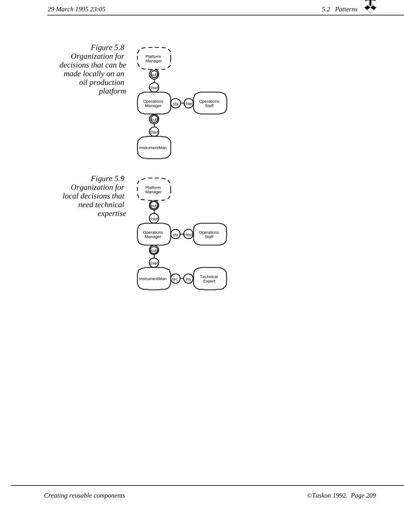
Figure 5.8 Organization for
decisions that can bemade locally on an
oil production platform
sub
chief
sub
chief
sta chief
PlatformManager
OperationsManager
OperationsStaff
InstrumentMan
Figure 5.9 Organization for
local decisions that need technical
expertise
tec ins
sub
chief
sta chief
sub
chief
PlatformManager
OperationsManager
OperationsStaff
InstrumentMan TechnicalExpert
29 March 1995 23:05 5.2 Patterns
Creating reusable components ©Taskon 1992. Page 209

Figure 5.10 Organization for
major decisions that need technical expertise and
involvement of head office
pla
are
tec ins
sub
chief
sub
chief
stachief
sub
chief
stachief
sub
chiefsta chief
sub
chief
President
AreaManager
AreaStaff
SectionManager
SectionStaff
DepartmentManager
PlatformManager
OperationsManager
OperationsStaff
InstrumentMan TechnicalExpert
The synthesis view of figure 5.11 shows the synthesis relationships between these models. Their details do not concern us here. The point is that patterns permit us to factor out common features and create a structure of reusable base models. The large body of possibly unrelated procedures becomes unified and consistent. We try to push the stable parts of our procedures up towards the base models, while the variable aspects are pushed down towards the derived models. If we do it right, we get an organization where it is easy to create new procedures and modify old ones, because the complex parts of the procedures are in the stable models, while the variable parts are in small and simple derivations.
A powerful tool for simplifying and
unifying procedures
5.2 Patterns 29 March 1995 23:05
©Taskon 1992. Page 210 Creating reusable components

Figure 5.11 Synthesis view
showing relationships
between example models
Decision Maker
Head OfficePlatform Organization
Specialist Organization
Major Decision Model
29 March 1995 23:05 5.2 Patterns
Creating reusable components ©Taskon 1992. Page 211

OOram Frameworks5.3
In a nutshellThis chapter is written for programmers, and you may safely skip it if you are not interested in programming.
An OOram framework is a reusable component containing a role model describing a general solution; a correlated set of base classes implementing its roles; and possibly descriptions of applicable constraints. We discuss the nature of an OOram framework and then give hints as to an appropriate development process.
The creation of an OOram framework is illustrated through an extensive case study in chapter 9.
A framework is a problem solution
Safe role model synthesis provides a nice and powerful way of specifying and using reusable class structures. A framework is an Object Specification model, which is created for the express purpose of being generally reusable through synthesis; together with a corresponding cluster of classes, which has been designed for subclassing. The framework is a packaged product that solves a specific problem; it includes instructions for when to use it and how touse it safely.
Figure 5.12 OOram frameworks support
design and implementation
Systemimplementation
Systemdesignmodel
Systemrequirements
model
Systemuser
model
OOramFramework
Systemof objects
29 March 1995 23:055.3 OOram Frameworks
Creating reusable components©Taskon 1992. Page 212

Frameworks support design and
implementation
Figure 5.12 illustrates that OOram frameworks provide the application programmer with solutions for the design and implementation stages. System design is simplified because the programmer can build on proven solutions by synthesizing the appropriate role models into her design. System implementation is simplified because the programmer can build her programs by inheriting from the corresponding base classes.
When we study the solutions to a number of different, but related, problems; we often find common subproblems which are costly to implement and hard to get right. We solve such subproblems once andfor all, so that application programmers in the future can build on the common solution and inherit its functionality and correctness.
In general, a framework is a
reusable module
In the software engineering community, a framework is commonly defined as a software module which facilitates the development of applications. A framework can provide functionality such as operatingsystem utilities, network communications, or interface development facilities.
The object-oriented framework is a set of
coordinated classes
An object-oriented framework is usually defined as a set of base classes that together describe a generally useful object structure. Application programmers use this object structure by deriving specialized classes from the framework's base classes.
OOram framework isa product
An OOram framework is a product designed for planned reuse. Insights into the best ways of solving given programming problems are captured in a collection of interdependent classes that are preparedfor subclassing. These classes are described by a role model which specifies the framework's essential functionality and hides all unnecessary details.
Patterns and frameworks are both reusable components that describe solutions to general problems. The difference is in the abstraction level: The pattern describes how the reader can solve a problem, while the framework provides a concrete solution. The pattern is tutorial in nature, it explains the essential components of the solution so that the reader can apply them. A framework takes care of many solution details so that the application programmer need not see them nor worry about them.
The application programmer inherits the solution by deriving her design model from the framework base model. At the implementation stage, she derives her application classes from the corresponding framework classes.
5.3 OOram Frameworks29 March 1995 23:05
©Taskon 1992. Page 213Creating reusable components

The core concepts of an OOram framework are illustrated in figure 5.13 (FOOTNOTE: This is a semantic view, its concepts and notation will be fully described in chapter 6.1). It shows how the framework role model consists of roles which are implemented as base classes. The application program is specified by a consistent mapping of the framework elements into corresponding elements in the application.
isImplementedBy
implements
has
isIn
playedBy
plays
playedBy
plays
isImplementedBy
implements
derivedClass
baseClass
has
isIn
Frameworkrole
model
DerivedModel
FrameworkRole
DerivedRole
FrameworkClass
DerivedClass
Supplier'sresponsibility
Consumer'sresponsibility
Figure 5.13 Semanticrelationships
between Framework concepts.
The synthesis can be implied when the derived model gets uncomfortably complex without giving new insights. It is often sufficient to create a role model for the application that follows the object structure of the framework without actually performing the synthesis operation.
The OOram framework should be developed under stringent quality requirements, so that the application programmer can rely on its correctness. It may also be beneficial to provide automated tools that help the application programmer conform to the framework's inherentconstraints.
We have learned the hard way that deriving our own software from somebody else's framework is a two-edged sword. We have achieved the expected gain in productivity and quality in our initial development, but we have also experienced chaotic situations when the framework provider improved the framework classes in new releases. The surface area between the frameworks and our derived classes was large and undefined, and it was very hard to determine theconsequences of framework changes.
Improving frameworks is a two-
edged sword
5.3 OOram Frameworks 29 March 1995 23:05
©Taskon 1992. Page 214 Creating reusable components
Even the vendor's bug fixes could cause catastrophies, because we were likely to have fixed the bug in our subclass. Just consider that a framework method returns a count which is one too large. Our subclass will have subtracted one from the returned count, which is OK until the framework is fixed. We will then use a count which is one too small. Or consider that the new version of the framework has made a subtle shift in the responsibility between some methods. We may have created an override for one of the methods in our subclass, and this method will now have the outdated responsibility.
We have without success tried to persuade various framework providers that they under no circumstances can modify a framework once it is published, but we must admit that their desire to improve their products is understandable. There is clearly a dilemma here. Oneof the great selling points for a framework is that it can be steadily improved over the years to the benefit of all consumers. But our experience indicates that such improvements can cause much rework and introduce subtle bugs in the derived applications.
The framework provider cannot
modify the frameworks at will
Specify and reduce surface area
Brad Cox [Cox 87] defines the surface area of a component as all thethings that must be understood and properly dealt with for one component to function correctly in combination with another component. Examples are class names; data names; message names and parameter types; time sequence constraints; garbage collection requirements; protection domains; and concurrency considerations.
We believe that the solution to the maintenance dilemma is to reduce and carefully define the surface area between the framework and its derivatives. The surface area of a good framework should be kept as small as possible. The framework provider is obliged to keep the surface unchanged, but is free to improve any of the hidden parts. Similarly, the framework consumer can only modify designated, visible parts of the framework. These are two of the main motivations for our insistence that an OOram framework must be much more than a collection of classes; it must include firm rules for its proper use. The optimum solution depends on the circumstances and the tools available: if the supplier can make it impossible to violate the rules; orif there is an automatic rule checker; or if rule conformance is a manual operation. The main thing is that the rules are clearly expressed and that the consumer abides by them.
It is appropriate to create an OOram Framework when the following conditions are satisfied:
When to create a framework
29 March 1995 23:05 5.3 OOram Frameworks
©Taskon 1992. Page 215Creating reusable components

The investment will be amortized because the problem will be recurring in the future and the framework will actually be used bythe consumers. The motivation may sometimes be a desire to ensure a uniform solution to a common problem; economic considerations will then be secondary.
1.
The phenomenon and the possible models describing it are well understood.
2.
Several implementations that include the phenomenon exist and are available for analysis.
3.
4. The requirements for a generally applicable framework are well understood.
It may also be appropriate to create frameworks under less than ideal conditions. The motivation could be that it is often better to dive into aproblem and then improve the solution as we learn and gain experience than it is to wait for the ideal conditions to materialize.
We suggest a possible list of operations for creating a framework. Youwill not necessarily perform them in the given sequence, and you maywant to add or remove some operations:
How to create a framework
Identify consumers and consumer needs. Consumer goals, needs, competence, working habits and preferences.
1.
2. Perform a cost-benefit analysis to estimate the pay-back of the investment in a new framework.
3. Perform reverse engineering of existing programs to understand all the issues and possible solutions. The devil is often in the details. Reverse engineering is a powerful method for identifying details that can play havoc with an otherwise pleasing architecture.
Specify the new framework in general terms, highlighting the problems to be solved and the goals to be reached
4.
Document the framework as a pattern describing how to use it to solve problems. This pattern enlarges the consumers' active vocabulary. We strongly recommend that this part shall be createdbefore the framework is designed and implemented. This is because a successful framework must be easy to understand and safe to use, and we rely on our in-born laziness to ensure that the interface to the consumer will be as simple as possible. (FOOTNOTE: You may enjoy reading the user manual for your favorite program and highlight all sentences that couldn't possiblyhave been written before the program.)
5.
5.3 OOram Frameworks 29 March 1995 23:05
©Taskon 1992. Page 216 Creating reusable components

Describe the framework's design and implementation for the consumers' understanding and passive vocabulary
6.
Inform the consumer community about the new framework, motivate them to use it, train them, and make the framework available to them.
7.
Further details in thecase study
Chapter 9 presents a case study that illustrates the creation of a major framework.
5.3 OOram Frameworks29 March 1995 23:05
©Taskon 1992. Page 217Creating reusable components

29 March 1995 23:055.3 OOram Frameworks
©Taskon 1992. Page 218 Creating reusable components

Chapter 6Additional role modeling concepts and
notation
This chapter is intended as a reference chapter to be read on a "need to know" basis. Its sections can be read in any sequence.
The role model may be observed from a number of perspectives and manipulated in many different views. The large number of views offered by the OOram method does not complicate it, because any given work process only applies the small selection that carry the most useful information.
Some central role model views were presented in chapter 2.5, we will here describe some additional ones:
1. The Semantic view describes the meaning we associate with the roles and their relationships.
The Process view describes the flow of data between the roles and the processing of the data in these roles.
2.
The State Diagram view describes the legal states of a role and the messages that trigger transition from one state to another.
3.
The Role List view gives an overview of the roles, their names, purpose, and attributes.
4.
The OOram Module encapsulates a number of models and controls high-level export and import of models.
5.
29 March 1995 23:05
Additional role modeling concepts and notation ©Taskon 1992. Page 219

6.1 Semantic view
In a nutshellThe semantic view describes the meaning we associate with the roles and their relationships. We rarely need the semantic view, since the collaboration view usually contains sufficient information.
The purpose of traditional semantic modeling is to create a representation of concepts and ideas along with the relationships between them. A common expression of semantic models is the entity-relationship (E-R) model [Chen 76], [Elmasri 94]. The two basic notions of E-R modeling of interest to us are as follows:
Three basic conceptsin traditional
semantic modeling
1. Entity. An entity represents the set of all instances of the same thing, idea or concept that we want to think about. An important attribute of an entity is a description of the meaning we attach to the entity instances. Entities are commonly denoted with a rectangle in E-R diagrams.
Relation. The entities of a problem domain are somehow related to each other. A relation is a representation of the meaning we attach to the relationship between entities. A relation is bi-directional. It describes what a first entity is in relation to a second, as well as what the second is in relation to the first. A relation is commonly denoted with a line connecting the entities. The line may be decorated with texts describing the relationships. Four different kinds of relations are commonly recognized:
2.
Aggregation. The two directions of the aggregation relation are commonly called consists-of and part-of.
¤
Use relation. The two directions of the use relation are commonly called uses and used-by.
¤
Subtype relation. The two directions of the subtype relation are commonly called is-a and kind-of.
¤
¤ Association. The two directions of the association are given names to describe the nature of the relationship.
The different kinds of relations are handled as follows:
1. Aggregation can be modeled by structures of interacting objects in several ways. We gave a detailed discussion of this topic in section 3.2.1: Aggregation: Linking models on different levels of abstraction.
6.1 Semantic view 29 March 1995 23:05
Additional role modeling concepts and notation©Taskon 1992. Page 220

Use relation. In an object model, this relation implies that an object sends messages to (uses) another object. This relation is shown explicitly in the Collaboration view that was described in section 2.5.2.
2.
Subtype relation. This is the base model - derived model relation that was described in chapter 3: Role model synthesis.
3.
4. Association. This is the relation shown in the OOram semantic view. It describes the meaning we attach to the relation.
System role<role name>
Environment role<role name>
Relation
Exactly one
One or more
Zero or one
The symbols are drawn close to the source role.They are annotated with a text describing themeaning of the relation in the direction ofthe arrowhead.
Symbol size and proportions are not standardized.Circles or ellipses may be used as alternatives.
Zero or more
<meaning associated with role>
Figure 6.1 Semantic view notation
The Semantic view is designed to capture the Entity-Relation kind of information for a system of interacting roles. We describe the concepts that the analyst associates with the roles and the relations between them. The notation is shown in figure 6.1. Figure 6.2 is a semantic view of the Purchasing model of chapter 2.3.2 on page 79??.
The semantic view describes the
meaning of the roles and their relations
cooperates with
cooperates with
banks with
is client of
is vendor to
is customer of
banks with
is client of
Vendor
SD
Enterprise PayerBank
PayeeBank
Figure 6.2 Semantic view of Purchase
model
6.1 Semantic view29 March 1995 23:05
Additional role modeling concepts and notation ©Taskon 1992. Page 221

Figure 6.3 shows an Entity-Relation diagram which corresponds to this example. The important difference is that the Entities are types; the diagram says that the Enterprise is client of some Bank, and the Vendor is client of a possibly different Bank.
Important difference between E-R and OOram semantics
is customer of
is vendor to
cooperates with
banks with
is client ofEnterprise
Vendoris client of
banks with
Bank
Figure 6.3 Corresponding Entity-Relation
diagram
Roles are like objects in that they have identity. If we should interpret figure 6.3 as a semantic view, it would mean that the Enterprise and the Vendor are both clients of the same Bank. Notice that figure 6.2 does not say they must be different; the same Bank object could play both roles.
The E-R model is on a higher abstraction level than the role model, and the E-R diagrams can be more compact than the corresponding semantic views. We need the concrete aspects of the role model because we want to reason about its behavior. In our example, we want to be able to analyze the model to convince ourselves that the Vendor who delivers the goods will also be the Vendor who receives payment. We can make this kind of arguments on the role level, but not on the type (or Entity) level. (FOOTNOTE: This problem is often called the equivalence of path problem in the E-R community)
29 March 1995 23:056.1 Semantic view
©Taskon 1992. Page 222 Additional role modeling concepts and notation
Collaboration view and semantic view --
different meaning!
There is a strong correspondence between the semantic view and the collaboration view. The semantic view describes how we think about the concepts and their relationships. The collaboration view shows how the objects collaborate in order to provide a faithful representation of our thoughts. A Relation represents a conceptual relationship, and a port represents the object's knowledge about one or more collaborators. The diagrams will have similar topologies, except that all relations need not be represented as message paths if there are no messages flowing between the associated objects. Further, the cardinalities of the ports may be more restricted than the cardinalities of the relations, since an object may not need to know all the associated objects at any given time.
We rarely need the semantic view, since the collaboration view in most cases contains much the same information.
The synthesis operation does not lead to semantic relations between the base model and the derived model. The reason is that there is no formal relationship between the meaning a human observer associateswith the roles and relations in a derived model and the meaning he or she associates with the roles and relations of the base models. It is the responsibility of the analyst to ensure that they are semantically consistent.
Structural relationship between
base and derived semantic views
There are formal relationships between the structures (syntax) of the derived and base models, and the general restrictions on roles, ports and cardinalities hold for the systems seen in the semantic views:
All roles in the base model must be mapped onto roles in the derived model.
1.
Every relation in all base models must be mapped onto a corresponding relation in the derived model.
2.
The cardinalities of the relations in the derived model must be consistent with the cardinalities of the corresponding relations in the base models. Specifically, the minimum cardinality of a derived model relation must be equal to or greater than the minimum cardinality of the corresponding base model relations; and the maximum cardinality of a derived model relation must be equal to or less than the maximum cardinality of the corresponding base model relations.
3.
29 March 1995 23:05 6.1 Semantic view
©Taskon 1992. Page 223Additional role modeling concepts and notation

No new notation The notation for the semantic view of the derived model is the same as the general notation described above. Inheritance relations may be added as shown in figure 3.31 on page 138??, but this is rarely of interest.
6.1 Semantic view 29 March 1995 23:05
Additional role modeling concepts and notation©Taskon 1992. Page 224

Process view6.2
In a nutshellA Process view describes the flow of data between roles and the processing of these data in the roles. We find the process view particularly useful for describing the flow of data and work procedures in human organizations.
Process analysis is a well established and powerful technique for describing how a system processes data. The OOram process view is based on the ideas of the IDEF0 (FOOTNOTE: Ref. [IDEF0 93]) standard and adapted to our general object model. The basic IDEF0 concepts, illustrated in figure 6.4, are as follows:
IDEF0 is a wellknown standard for Process analysis
Mechanism - the actor (person, role, machine, resource, competence, software system, ...) that deal with HOW, or the means by which the process is done. E.g., what people, machines,programs, etc. are required.
1.
2. Input - data or "raw materials" undergo a process or a series of activities and are transformed into output.
3. A process is defined as a series of operations contributing to a specific purpose. In the IDEF0 technique, a process is described by a verb or verb phrase and is represented graphically by a rectangle.
Control - data controlling or influencing the way in which the process converts its input into output. The control affects the mode of activities, and may be parameters and rules to be used bythe mechanisms, such as determining which output is produced, how much, and when it is produced (e.g.,directions, standards, purposes, timing, quantities, etc. which control or direct the way in which the activity is performed.)
4.
Output - data or "products" are produced by, or result from, the process.
5.
29 March 1995 23:05 6.2 Process view
Additional role modeling concepts and notation ©Taskon 1992. Page 225
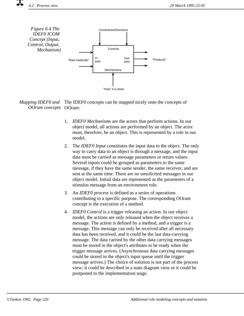
Controls
In-puts
Mechanisms
Out-puts"Raw materials"
Constraints/Directions
"How" it is done
"Products"
Figure 6.4 The IDEF0 ICOM
Concept (Input, Control, Output,
Mechanism)
The IDEF0 concepts can be mapped nicely onto the concepts of OOram:
Mapping IDEF0 and OOram concepts
1. IDEF0 Mechanisms are the actors that perform actions. In our object model, all actions are performed by an object. The actor must, therefore, be an object. This is represented by a role in our model.
The IDEF0 Input constitutes the input data to the object. The onlyway to carry data to an object is through a message, and the input data must be carried as message parameters or return values. Several inputs could be grouped as parameters to the same message, if they have the same sender, the same receiver, and are sent at the same time. There are no unsolicited messages in our object model. Initial data are represented as the parameters of a stimulus message from an environment role.
2.
An IDEF0 process is defined as a series of operations contributing to a specific purpose. The corresponding OOram concept is the execution of a method.
3.
IDEF0 Control is a trigger releasing an action. In our object model, the actions are only released when the object receives a message. The action is defined by a method, and a trigger is a message. This message can only be received after all necessary data has been received, and it could be the last data-carrying message. The data carried by the other data carrying messages must be stored in the object's attributes to be ready when the trigger message arrives. (Asynchronous data carrying messages could be stored in the object's input queue until the trigger message arrives.) The choice of solution is not part of the process view; it could be described in a state diagram view or it could be postponed to the implementation stage.
4.
6.2 Process view 29 March 1995 23:05
Additional role modeling concepts and notation©Taskon 1992. Page 226

Output - data or "products" are produced by, or result from, an action. The output from one object must be input to another, and must be transmitted from the data source as a message. This message will be received by some other object as described under Input above.
5.
The notation for a Process view is shown in figure 6.5. Roles are shown as super-ellipses, actions as rectangles, data as parallelograms, and data flow as arrows.
The OOram process view
Figure 6.5 Process view notation
A role,responsible for performing all actions in same column
An action performed on received data
A data set which is transferred as message parameter(s)
Data transferred in direction of arrow
The use of the process view is illustrated in figure 6.6. Since objects are the only possible actors in an object-oriented system, every action has to be associated with a role. The role responsible for an action is indicated by its column. The responsibility for the data being transferred is undefined.
29 March 1995 23:05 6.2 Process view
Additional role modeling concepts and notation ©Taskon 1992. Page 227

Figure 6.6 Process view of Purchase
modelEnterprise Vendor Payer
BankPayeeBank
<Establish need><Prepare request>
<Prepare bid>
<Select bid><Prepare order>
<Process order><Prepare goods>
<Prepare invoice>
<Store goods><Prepare payment>
<Process order><Prepare transfer>
<Credit account><Prepare advice>
<Update books>
requestforbid
bid
order
goodsand
invoice
paymentorder
transferorder
creditadvice
Composite actions supported
Most process analysis methods support composite actions, which are actions that are later decomposed into a number of smaller actions with data flowing between them. This is easily supported by the process view with one caveat: if the composite action is performed by several roles, a corresponding virtual role must be defined to maintain the one-to-one relationship between process actors and roles. The decomposed process view will begin with a single action and end withanother action, both being parts of the composite actions.
29 March 1995 23:056.2 Process view
Additional role modeling concepts and notation©Taskon 1992. Page 228

Conventional data flow analysis represents data stores as special elements. The only way to store data in our object model is as object attributes. We must, therefore, represent a data store as a role in a column in the diagram. The data store object receives and transmits data through messages, the data stored at any time may be derived from the data store's input data. Data store objects will normally be persistent, their contents will survive individual program executions.
Data Stores are special objects
Processes lost in unsafe synthesis
A process that is described in a role model cannot, in general, be assumed valid in a derived model. The reason is that in the general, unsafe synthesis, the base model activities are not preserved in the derived model.
Processes inherited in safe synthesis
The essence of safe synthesis is that the base model activities are preserved in the derived model. In these cases, the processes of the base model are preserved in the derived model. We have suggested two safe synthesis constructs where the destiny of a process after a synthesis operation corresponds to the destiny of the stimulus message that starts it:
1. Activity superposition. The base model stimulus messages become derived model stimulus messages. The base model activities become independent derived model activities. The base model processes becomes independent derived model processes. This is a trivial case that will not be discussed further.
Activity aggregation. The base model stimulus message is sent from one of the derived model methods. The base model activity becomes a subactivity and the base model process becomes a subprocess under this method in the derived model.
2.
We illustrate activity aggregation by an example from the DerivedTravelExpense model.
Activity aggregation means to splice base
model process into derived model
process
6.2 Process view29 March 1995 23:05
Additional role modeling concepts and notation ©Taskon 1992. Page 229

Figure 6.7 ExpenseAccount
process viewENT
TravelerENT
AuthorizerENT
BookkeeperENT
Paymaster
Desireto
travel
<Determine OK>
travelPermission
Request:
<Order tickets><Travel>
<Write exp.rep.>
travelPermission:
<Check OK>
expenseReport:
<Check><Bookkeeping>
authorizedExpenseReport:
<Arrange for payment>
paymentRequest:
Figure 6.7 shows a process view corresponding to the scenario for the TravelExpense model in figure 2.15 on page 75??. Similarly, figure 6.8 shows the process view corresponding to the scenario for the AirlineBooking model in figure 3.5 on page 109??.
Figure 6.8 AB AirlineBooking
ProcessAB
Traveler
ABBooking
Clerk
ABTravelAgent
ABBook
Keeper
ABPaymaster
Ordertickets
Ordertickets
Travelspecification
Issue tickets.Prepare invoice
Travelspecification
Processtickets
and invoice
Ticketsand invoice
Note costfor later use
Ticketsand cost
information
Processinvoice
Authorizedinvoice
Sendpayment
Paymentrequest
Processpayment
Payment
29 March 1995 23:056.2 Process view
Additional role modeling concepts and notation©Taskon 1992. Page 230

When we synthesize the two models into the DerivedTravelExpense model, the AirlineBooking activity is spliced into the method for the travelPermission-message. Compare the scenario of figure 3.13 and the method views of figure 3.14 and 3.15 on page 114?? with the combined process view of figure 6.9. You will appreciate that different views highlight different aspects of a common model, and that you select the views that are most convenient and informative for your purpose.
Figure 6.9 DerivedTravelExpens
e process viewDTE
TravelerDTE
Authorizer
DTEBook
Keeper
DTEBooking
Clerk
DTETravelAgent
DTEPaymaster
Preparetravel.
Issuepermission.
Travelpermission
request
Order tickets.
Travelpermission
Order tickets.
Travelspecification
Issue tickets.Prepare invoice.
Travelspecification
Processtickets
and invoice.
Ticketsand invoice
Processinvoice.
Authorizedinvoice
Note ticket cost.Travel.
Prepare expense account.
Ticketsand cost
information
Sendpayment.
Remuner-ation
request
Processpayment.
Payment
Checkexpenseaccount.
Expenseaccount
Processexpenseaccount.
Authorizedexpenseaccount
Arrange foraddition tonext salarypayment.
Remuner-ation
request
Inserted AirlineBooking activityspliced into ExpenseAccountmethod
6.2 Process view29 March 1995 23:05
Additional role modeling concepts and notation ©Taskon 1992. Page 231

6.3 State Diagram view
In a nutshellThe State Diagram view describes the legal states of a role and the messages that trigger transition from one state to another.
State Diagrams belong to internal
perspective
We zoom in to focus on an individual role or object, and study its behavior in the form of a state diagram. The overall pattern of collaborating roles in the role model has disappeared; all we see are the messages received from the object's environment. The sending of these messages is out of sight.
State diagrams are suitable for the detailed specification of role behavior without actually writing the code. We do not generally specify state diagrams for our roles, but they are useful in certain cases -- notably cases involving multiple message threads such as is often found in telecommunications and real time systems.
The volume of the description increases dramatically with the introduction of state diagrams, and you should only use them if you really need them and then only at a late stage in the design process.
Use state diagrams sparingly and late in
the process.
The state diagrams are omitted if the design can be made so simple that the problem can be postponed to the implementation stage. The main advantage is that the volume of the models is drastically reducedso that they are easier to create, easier to check, and easier to modify.
We cannot reason about the dynamic correctness by studying a singlestate diagram. We must extend our scope to the complete role model to determine the dynamic correctness of the base models, and we mustconsider the state diagrams of all synthesized roles to determine if the base model correctness is preserved in the derived model.
The theory and usage of state diagrams is a specialized subject which we will not attempt to cover adequately in this book. We will content ourselves with indicating how state diagrams may be defined in the context of a role in a role model, and refer you to the literature for further details. (See for example [Bræk 93]).
6.3 State Diagram view 29 March 1995 23:05
©Taskon 1992. Page 232 Additional role modeling concepts and notation
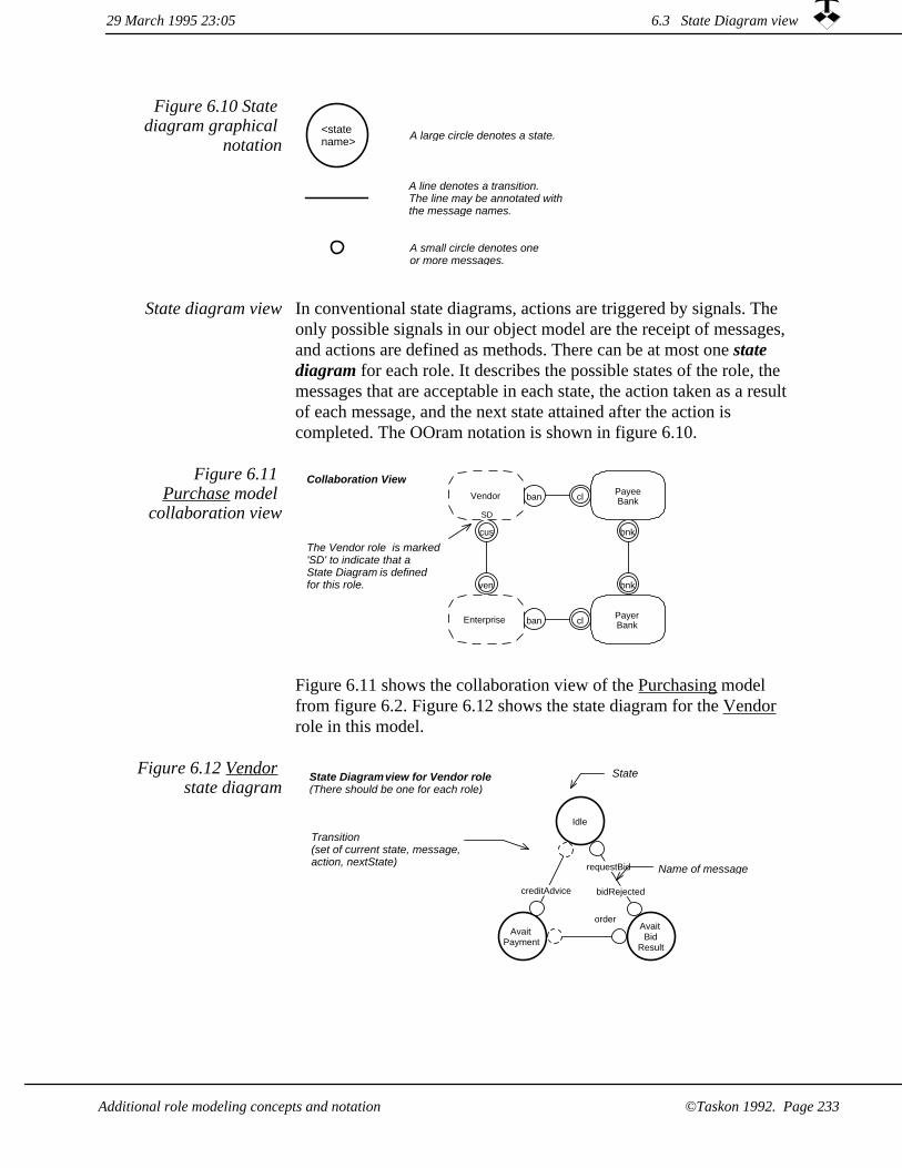
A large circle denotes a state.<statename>
A line denotes a transition.The line may be annotated with the message names.
A small circle denotes oneor more messages.
Figure 6.10 State diagram graphical
notation
In conventional state diagrams, actions are triggered by signals. The only possible signals in our object model are the receipt of messages, and actions are defined as methods. There can be at most one state diagram for each role. It describes the possible states of the role, the messages that are acceptable in each state, the action taken as a result of each message, and the next state attained after the action is completed. The OOram notation is shown in figure 6.10.
State diagram view
ban cl
cus
ven
ban cl
bnk
bnk
The Vendor role is marked'SD' to indicate that a State Diagram is definedfor this role.
Collaboration ViewVendor
SD
Enterprise PayerBank
PayeeBank
Figure 6.11 Purchase model
collaboration view
Figure 6.11 shows the collaboration view of the Purchasing model from figure 6.2. Figure 6.12 shows the state diagram for the Vendor role in this model.
Figure 6.12 Vendor state diagram
Idle
AvaitBid
Result
AvaitPayment
requestBid
creditAdvice bidRejected
order
State Diagram view for Vendor role(There should be one for each role)
State
Transition(set of current state, message, action, nextState)
Name of message
6.3 State Diagram view29 March 1995 23:05
Additional role modeling concepts and notation ©Taskon 1992. Page 233

We shall now discuss how we can preserve a successful state diagram through a safe synthesis operation. Note that we restrict our arguments to sequential message semantics. The safe synthesis of state diagrams for parallel processes is a research topic; but we expect that the preservation of the activity integrity will hold the key to success.
Compose the derivedstate diagram in safe
synthesis
The state diagram of a derived role will in some sense be a product of the state diagrams of its base roles. If a base role, M, has states m1, m2 and m3; and another base role, N, has states n1 and n2; the derivedrole may have the states m1n1, m1n2, m2n1, m2n2, m3n1 and m3n2. This is illustrated in figure 6.13.
General synthesis leads to state space
explosion
Figure 6.13 General state diagram
synthesis
m3n2m2n2
m1n2
m2 m3
m1
m3n1
m1n1
m2n1
n1 n2
Initial stateInitial state
Initial state
State Diagram for role M
State Diagram for role N
Composite State Diagram for derived role MN
Activity superposition
Our two safe synthesis constructs are much simpler. We start with activity superposition. We notice that the base model activities are to be retained as independent activities in the derived model; and that at most one activity can be performed at the time. The effect is that the initial state of all derived roles will be the combination of the base model initial states, and rest of the base model state diagrams will appear as separate structures with no transitions between them. This isillustrated in figure 6.14 for role MN, which is derived from roles M and N.
6.3 State Diagram view 29 March 1995 23:05
Additional role modeling concepts and notation©Taskon 1992. Page 234

m1n2
m2 m3
m1
m3n1
m1n1
m2n1
n1 n2
Initial stateInitial state
Initial state
State Diagram for role M
State Diagram for role N
Composite State Diagram for derived role MN
Superposition
Figure 6.14 Activity superposition
The state diagrams for all derived roles are formed by joining the base model state diagrams at their initial state and nowhere else.
In activity aggregation, the activity of one base model is triggered as asub-activity in one of the methods of another model. Figure 6.15 illustrates an example when the state diagram of role N is encapsulated within a single state in the state diagram for role M.
Activity aggregation
m2n2
m2 m3
m1
m3n1
m1n1
m2n1
n1 n2
Initial stateInitial state
Initial state
State Diagram for role M
State Diagram for role N
Composite State Diagram for derived role MN
Aggregation
Figure 6.15 Activity aggregation
6.3 State Diagram view29 March 1995 23:05
Additional role modeling concepts and notation ©Taskon 1992. Page 235

Notice that the state diagrams of all other derived roles are copies of their respective base model state diagrams. The interdependence between base model state diagrams is only allowed in the triggering role.
Also notice that attributes may not be modified by an action method ifthis causes a state change in a different base model, because such change modifies base model behavior.
29 March 1995 23:056.3 State Diagram view
Additional role modeling concepts and notation©Taskon 1992. Page 236

6.4 Role List view
In a nutshellThe Role List view gives an overview of the roles, their names, purpose, and attributes.
The role list view is used to give an overview of the roles and to showsome of their properties, you should select the ones that are useful in your context:
Many data items associated with roles
1. role name, the role's unique identifier within the role model
explanation, giving the meaning that the analyst associates with the role and its responsibility in the community of roles in the rolemodel.
2.
3. attributes. For each attribute you may specify:
attribute name, the attribute's unique identifier within the role¤¤ explanation, giving a free text description of the attribute
type, specifying the type of the attribute. This is often omitted,but is particularly interesting if the attribute is a reference to a role in another role model.
¤
Figure 6.16 Specification
example written in the OOram language
role 'Vendor' explanation "An object which desires to supply goods."attribute 'accounts'
explanation "To keep track of outstanding accounts with customers."role 'Enterprise'
explanation "An object which desires to purchase goods."role 'PayerBank'
explanation "The bank of the Enterprise."role 'PayeeBank'
explanation "The bank of the Vendor."
Formal language defined, but informalreport often easier to
read
The form of the role list should be adapted to its purpose. If precision is of paramount importance, write the specification in the OOram language as exemplified in figure 6.16 and discussed in depth in appendix A. If the purpose is to communicate your ideas to colleaguesand clients, an informal variant as exemplified in figure 6.17 may be better.
Figure 6.17 Specification
example written informally
role 'Vendor' "An object which desires to supply goods."attribute 'accounts' "To keep track of outstanding accounts with customers."
role 'Enterprise' "An object which desires to purchase goods."role 'PayerBank' explanation "The bank of the Enterprise."role 'PayeeBank' "The bank of the Vendor."
29 March 1995 23:05 6.4 Role List view
©Taskon 1992. Page 237Additional role modeling concepts and notation

Modeling in the large: The OOram Module6.5
In a nutshellWorking with a large number of interdependent models can be confusing. Arbitrary synthesis relationships may lead to complex structures that are hard to manage. OOram Modules provide a way to group role models, hide details and declare certain models to be visible and available for import into other modules.
The development of a large system will often be distributed among several teams who are separated in space or time. It is an administrative goal to keep the dependencies between the teams as small and simple as possible in order to reduce the need for coordination and the danger of undetected inconsistencies.
As mentioned earlier, Brad Cox [Cox 87] defines the surface area as everything that is visible at the interface between a supplier and a consumer. This interface includes everything the consumer needs two know and understand such as data element names and types, function names, number of parameters and their types, restrictions on time sequence of operations, concurrency and protection domains. Techniques for reducing the surface area between packages in the realm of programming is called programming-in-the-large. We similarly define modeling-in-the-large as techniques for packaging models and minimizing the surface area between model packages.
Modeling in the large
The synthesis operation establishes a dependency between the base model and the derived model. Ad hoc synthesis between a large number of models can easily lead to a chaotic structure that is hard to create and even harder to modify. We want to group role models, and encapsulate each group so that we can control the features that shall be visible to other groups.
A OOram Module is a package
The OOram Module is an encapsulation of OOram models. The OOram Module supports modeling-in-the-large by exporting one or more carefully contrived models and hiding other models and model details which are deemed internal to the module.
An important application of modules is to package reusable components. The work process will then be somewhat different, this was discussed in chapter 5: Creating reusable components.
6.5 Modeling in the large: The OOram Module 29 March 1995 23:05
©Taskon 1992. Page 238 Additional role modeling concepts and notation

It is appropriate to create an OOram module if the following conditions are satisfied:
The total set of role models gets too large to be easily manageable.
1.
The models can be arranged into distinct groups.2.
3. There are details in the models of the group that need not be visible to the derived models outside the group. Encapsulation and information hiding is then appropriate.
4. The exported models are reasonably stable.
A Module may import role models from other Modules and synthesize them into the Module's own models. Imported object specifications specify classes that have been implemented and that may be subclassed in the importing module. A selected subset of the information defined in the Module may be declared as export featuresand thus made available to other modules as illustrated in figure 6.18.
Figure 6.18 The OOram Module
Role Models Object Specifications Export ModelsImport Models
Module
An Export Model is a model which is designed to be reused through synthesis into another model.
An Export Model consists of the following parts:
1. A role model or object specification.
2. A coordinated set of classes that implement the model. The classes are designed to be subclassed in a controlled manner. (optional)
Rules for the import of the model, blocking the subclassing of some classes and restricting the modifications permitted in the subclasses of others. The rules shall be designed to ensure the static and dynamic integrity of the export model. Many different rules can be contemplated; they should preferably be automatically enforceable or checkable (optional).
3.
29 March 1995 23:05 6.5 Modeling in the large: The OOram Module
Additional role modeling concepts and notation ©Taskon 1992. Page 239

Modules support concurrent engineering of large systems. A team canencapsulate a system within a module, declare the role models it imports from other modules; declare details as private and thus hide them within the module; and declare certain models as export models and thus make them available to other teams.
Modules support division of authority and responsibility between development teams, and are used to express the high level system architecture. The following operations may be used to determine the modules and create the top level architecture (not necessarily performed in this sequence):
Module structure expresses system
architecture
1. System characterization. Write a short, free form (prose) description of the system, its purpose and main features.
Identify and understand the modules. Factor the information requirements of the total system and assign to modules. Similarly factor the processing requirements of the total system and assign to modules. Iterate to make modules represent "natural" entities ofa reasonable size and complexity.
2.
Determine interdependencies. Determine the information transfer requirements between modules. Initially, this is done by specifying the nature of information transferred (role model, object specification, etc.) and its area of concern. The models are later augmented with more detailed information as needed.
Iterate step 2 and 3 to minimize intermodule dependencies.
3.
Assign the detailing of each module to a developer or development team.
Iterate steps 2, 3 and 4 to revise export/import information and to maintain simple intermodule dependencies.
4.
Programming-in-the-small relatively
simple
Programming a small system in an incremental programming environment such as Smalltalk is relatively simple. Using exploratory programming techniques, a satisfactory set of classes and methods will usually evolve naturally, and the system source code will usually provide adequate documentation.
When the programs grow so that their logic is not immediately apparent from the code, a logical layer is added where the systems are described by one or more role models.
Medium-sized programs described
by role models
6.5 Modeling in the large: The OOram Module 29 March 1995 23:05
Additional role modeling concepts and notation©Taskon 1992. Page 240
Programming-in-the-large is another
matter
For very large systems, the number of role models makes it hard to manage them and keep track of their interdependencies. We then needa methodology that helps us separate the total system into understandable parts and to manage their integration. We add the rigor of a systematic design methodology to control the development process and to document its results. We get a structure of related modules, each containing a number of related models. Each model is presented through a number of different and overlapping views. All these modules, models and views must be made consistent in all their details.
The role models prescribe permissible message sends; these must be consistent with the messages actually sent by the programs. Role models build on other role models through synthesis. If a base model is changed, the derived models must all be updated accordingly. Toolscan be provided to check and help the programmer in the updating tasks, but hard work is still involved and it is easy to get lost in all the petty details.
The good news is that the discipline, modularity and precision provided by a good analysis and design methodology makes it easier to scale to real-sized projects. The structure that modularization imposes on the design gives other people a chance to understand whathas been done and why it was done. Quality checks can be applied at different levels of abstraction by independent auditors. The logical descriptions makes it possible to apply automated tools to check that the programs actually conform to the designer's intentions.
The good news
We offer the following advice for good working habits:
1. It is crucial to design the architecture right, which means that the choice of modules and their exported functionality should be stable and their surface area should be minimized. The hassle involved in system updates is immensely reduced if one can get this right.
Keep modules and role models brief and sketchy until the architecture and all naming conventions are stable.
2.
3. Exploratory design and implementation of modules is a powerful idea that yields good results in a short period of time. But keep the architecture stable! Exported models should be changed infrequently and only after careful consideration.
4. Keep it lean and mean. The models exported from the modules should be simple -- easy to understand and easy to apply.
29 March 1995 23:05 6.5 Modeling in the large: The OOram Module
Additional role modeling concepts and notation ©Taskon 1992. Page 241

Two modules may be related in three different ways as follows:Different module relations
1. Peer-to-peer module relation. The two modules represent phenomena on the same abstraction level, and each is responsible for a part of the total system. A typical application is when the functionality of a domain is to be made available to another domain in a controlled manner. This is illustrated in the example below.
Aggregation relation. The two modules belong on different abstraction levels. What appears as a single object on one level appears as structure of objects on the next level down, and what appears as single operations on one level are expanded into complete activities on the next level down.
The server in a client-server combination will typically be packaged in a module. It will export one or more descriptions of the service as seen from the clients, and will hide all details about its realization.
2.
3. Generalization-specialization. A module may define the solution to a general problem; another module may import this solution and specialize it.
We could, for example, create a general module for making minorexpenditure decisions in our company. The TravelExpense model could then import and specialize its export model. Other examplesare given in chapter 5: Creating reusable components.
The TravelExpense and AirlineBooking models described in chapters 2.3 and 3.1 both included facilities for reimbursing someone -- they were slightly different for the reimbursement of the traveler and the travel agent. It might be better if we had standardized the reimbursement procedure and applied it consistently in all cases. A possible solution would be to create an Accounting module; a module that includes a great deal of financial and accounting details. This module exports a Reimbursement model that is imported by the TravelManagement module. The TravelExpense and AirlineBooking models are now derived from the common Reimbursement model. This solution is shown in full graphical notation in figure 6.19 and in an abbreviated form in figure 6.20.
Module example
29 March 1995 23:056.5 Modeling in the large: The OOram Module
Additional role modeling concepts and notation©Taskon 1992. Page 242

Figure 6.19 Full graphical module
notationDerived
TravelExpensemodel
AirlineBookingmodel
TravelExpensemodel
Reimbursementmodel
TravelManagement ModuleAccounting Module
Exported base model Derived modelsModels internalto Accounting
In the full graphical notation, a module is shown as a rectangle enclosing its model symbols. The module name is written on its top boundary. Export-Import is shown as synthesis arrows crossing the module boundaries.
TravelManagement ModuleAccounting ModuleFigure 6.20 Abbreviated
graphical module notation
In the abbreviated module notation, individual models are suppressed and we show the module relationships as synthesis arrows between the modules themselves.
In chapter 12: A Value Chain for Intelligent Network Services, we willpresent an extensive case study describing a possible commercial organization for creating, deploying and using advanced telecommunication services. The notion of modules is an important part of its technological foundation, facilitating the transfer of technology between different operators and protecting critical resources which need to be controlled by the technology supplier.
Module architecture case study
Modules make OOram technology scale to very large
systems
Modules provide system organization and information hiding facilities that make it feasible to manage very large systems. A bank may create a Customer Module that exports certain models which its customers can import into their own systems and thus integrate banking with other operations. The Customer Module will also be partof the bank's system architecture and be integrated with other modules through a different set of export models.
This is an enormously important result. A customer designs, implements and understands its information systems, just as the bank designs, implements and understands its system. The two system worlds are integrated through shared models so that they technically constitute a coherent whole, yet no single person or group of persons need have an overview of the total system.
29 March 1995 23:05 6.5 Modeling in the large: The OOram Module
©Taskon 1992. Page 243Additional role modeling concepts and notation

29 March 1995 23:056.5 Modeling in the large: The OOram Module
©Taskon 1992. Page 244 Additional role modeling concepts and notation

Chapter 7Case study: Development of a business
information systemIn a nutshellObjects everywhere! We use objects to model the organization of the enterprise and the computer system architecture. We use objects to model the human work procedures and the symbiosis between humans and their personal computers. We use objects to describe the user interface.
We suggest that business information processing can conveniently be represented by three interrelated role models: the first is a model of the human work processes; the second is a model of the human tasks with the corresponding computer tools; thethird is a model of the shared information. This model triad is illustrated by a case study of the travel expense system mentioned earlier.
Enterprise is the term commonly applied to all kinds of work organizations. We find enterprises in the public sector ranging from the offices of central government to the local fire brigade. We find enterprises in trade and industry, and we find them in the voluntary organizations. Their common characteristic is that they provide a stable framework to support people working together in an organized manner towards a common goal.
An enterprise is a work organization
Value is created when a person performs some useful task. This task will be part of a work process that involves the person and possibly other persons as indicated in figure 7.1.
Work process results in value creation
Figure 7.1 A work process consists of a
sequence of tasks task
task
task
task
task
task
29 March 1995 23:05
Case study: Development of a business information system ©Taskon 1992. Page 245

The professional needs a consistent
and integrated information environment
The professionals performing the tasks will be supported by a combination of methods, procedures and tools which we call their information environments. A personal information environment is an integrated and unified interface to the world of computer-based information, customized to their owner's tasks and designed to be an effective aid in all his or her information processing activities: the retrieval of information, the creation of new information based on the person's skill, experience and competence, and the person's cooperation with teammates as well as other people both within and outside the organization. This symbiosis of person and information environment is illustrated in figure 7.2.
Enterprise level
Computer level
Personalinformationenvironment
Integratedinformationservices
Figure 7.2 Personal information
environments support the members of the organization intheir individual work
and their cooperation
A person does not work in isolation, and our symbiosis of person and information system could be repeated on all levels of the organization such as the team, the department, and the division as illustrated in figure 7.3. In this model, every organizational unit is modeled as an object, which is implemented as a combination of humans and computers. Interaction between the objects can take place on the human level or the computer level as appropriate. This system architecture could implement new and powerful ways of organizing our business.
Architecture should support cooperation
on all levels
29 March 1995 23:05
Case study: Development of a business information system©Taskon 1992. Page 246

Figure 7.3 Multi-level man-machine
symbiosis
A two dimensional client-server architecture
We believe that the person oriented approach is valuable, and may indeed be the driving force behind the personal computer revolution. It is distinct from the traditional function oriented approach, but does not replace it. One dimension is that a person needs to integrate all hisor her information processing facilities. The other dimension is that a company needs integrated functions. For example, a company needs integrated systems for computer-aided design, for materials management, for project control, and for economic management. A project manager performing the task of assigning people to the project's activities needs a tool that provides simultaneous access to the personnel function, the manpower loading function and the projectcontrol function.
We clearly need an overall systems architecture which combines both approaches. We advocate the specialized client-server architecture that is illustrated in figure 7.4. The client parts provide task-oriented information environments tailored to the needs of the individuals, and the server parts provide the functional integration. The name we have chosen for this architecture is the Task/Tool/Service architecture, because it describes how an individual's tasks are supported by customized tools that access common information services on behalf of the individual.
We have chosen the term tool to denote an artifact that a person employs to perform a task, and the term User Information Environment to denote the integrated set of tools employed by a person. We have chosen the term Information Service to denote a service object which is responsible for managing certain information such as accounting information or materials management information.An Information Service object will typically encapsulate a database oran old application system (frequently called a legacy system).
29 March 1995 23:05
©Taskon 1992. Page 247Case study: Development of a business information system

UserInformationEnvironment
UserInformationEnvironment
UserInformationEnvironment
UserInformationEnvironment
InformationService
InformationService
InformationService
Enterprise Outside world
Communication
Tasks
Tools
Services
Figure 7.4 Task/Tool/Service
System Architecture
The architecture of figure 7.4 supports many levels of integration as illustrated in figure 7.5.
The architecture supports many levels
of integration
WithinService
BetweenServices
Enterprise Outside world
Communication
Tools Between tools
Between people
Through Tool
Figure 7.5 Levels of Integration
Integration within a service. A service may encapsulate a database, which is used to integrate all functions pertaining to the domain served by the service.
1.
Direct integration between services. A service may call upon another service, it then becomes a client of that service. This levelof integration should be used with discretion, because it could make the total system very difficult to change. One viable discipline is suggested in figure 7.3, where team services may be clients of the department services, which in their turn may be clients of the division services.
2.
Integration of services via tools. A tool may be the client of several services, and may be used to move information between them. This kind of integration is very flexible since tool programsshould be much smaller and simpler than service programs. It is easier to maintain system flexibility through evolution.
3.
29 March 1995 23:05
©Taskon 1992. Page 248 Case study: Development of a business information system
4. Integration between tools. In principle, a tool may be the client ofanother tool so that information may be transferred between them.Tools should be created and phased out fairly rapidly to reflect changes in work procedures and personal preferences. Tool-tool integration makes the total system more rigid and harder to change. We recommend that you avoid this kind of integration.
5. Integration between people. Even in a computer intensive environment, people must still be encouraged to communicate both formally and informally. This communication can be person-to-person, through telephone, fax or through an electronic message system.
Three levels of information system
modeling
The Task/Tool/Service architecture tells us that we have to perform analysis and design on three levels. The levels will be represented by three distinct, but interdependent, models, with each of them offering its own insights into the problem and its solution. The levels are illustrated in figure 7.6 and described in detail in the following subsections.
Enterprise model, modeling how people work and interact in order to achieve the given purpose. This corresponds to the System User Model of figure 1.17 on page 44??.
1.
Information model, modeling the subject of the work described inthe Enterprise model. The information will ultimately be handled by an appropriate Information Service. This is one of the System Requirements Models of figure 1.17.
2.
3. Task/Tool/Service model, modeling the tasks and the interfaces between the people and the Information model. This is another System Requirements Model.
The Task/Tool/Service and the Information models can be elaborated on several levels of abstraction.
29 March 1995 23:05
©Taskon 1992. Page 249Case study: Development of a business information system

Figure 7.6 Personal information
environments support the members of the organization intheir individual work
and their cooperation
Enterprisemodel
Task/ToolServicemodel
Informationmodel
The three models are interrelated as illustrated in figure 7.7. The enterprise model defines the tasks for the Task/Tool/Service models and the information that needs to be represented in the information model. Each Task/Tool/Service model defines a number of operations that have to be supported by the information model.
Enterprise model
Task/Tool/Servicemodels Information models
tasks required information
operations
Figure 7.7 Relationships
between the three models
Analysis and design are opportunistic
We begin by modeling the current situation, and usually create the Enterprise model and the Information model in parallel. We next develop a corresponding pair of models for the desired, future situation as illustrated in figure 7.8. Purists may want to keep the current and the future models distinct; in practice, we often permit the one to gradually evolve into the other. We continually iterate between the future Enterprise and Information models because new ideas for organizing the enterprise lead to new demands on the information, andinsights into possible information structures suggest opportunities for improved organizations.
The scope of the project should be under continuous scrutiny. The scope may be expanded to incorporate new ideas for increased functionality, or it may have to be reduced because some of the original ideas may prove impractical or infeasible.
29 March 1995 23:05
Case study: Development of a business information system©Taskon 1992. Page 250

Once the future Enterprise and Information models begin to stabilize, we introduce the Task/Tool/Service level modeling. We continue to iterate between Enterprise, Information and Task/Tool/Service modelsuntil analysts and users agree they have reached a satisfactory solution.
We will later stress the importance of user participation in these early stages of the development process. We recommend that you consider using early prototyping to ensure that the users fully appreciate the consequences of the proposed specifications.
Scope
FutureTask/Tool/Service
model
CurrentEnterprise model
CurrentInformation model
FutureEnterprise model
FutureInformation model
Figure 7.8 A development process
The Task/Tool/Service architecture described in this section may be studied on two levels. It may be taken as a proposed solution to an important set of problems. Or it may be taken as an example of three very interesting relationships between models: The actions of the Enterprise model define the activities of the Task/Tool/Service model;the data of the Enterprise model define the objects of the Information model; and the actions of the Task/Tool/Service model define the operations of the Information model.
Summing up
We will now create the three models for the travel expense example introduced earlier. We will create an enterprise model, an informationmodel, and a task/tool/service model that focus on the needs of the Authorizer role.
29 March 1995 23:05
©Taskon 1992. Page 251Case study: Development of a business information system

Enterprise model7.1
In a nutshellWe create an object model of an organization in the context of a certain work procedure. The case we have chosen is a possible work procedure for the management of travel expense accounts. This problem was introduced in chapter 2. We now give it a more detailed treatment.
Business process reengineering
The essence of business process reengineering is to re-evaluate the goals of an enterprise and the means it employs to reach them. Of prime importance is looking at the enterprise in a new light, getting new insights and finding new ways to reach old and new goals.
It has been said that invention consists of 5% inspiration and 95% perspiration. The perspiration part of business process reengineering is to design the new organization, its procedures and its information systems. It is usually appropriate to create two sets of models: `as is' models describe the current way of doing things, and `reengineered' models describe the future organization and its systems.
Based on the idea of business reengineering presented in [Hammer 93], we consider a procedure in the light of the overall goals of the enterprise. Is the procedure really necessary? If the answer is yes, could we achieve the required results in a more effective manner? Is itreally necessary to assume that everybody wants to cheat the system, or could we trust people to do the right thing? In this case study, we will assume that the inspiration part is completed, and that we now want to create a detailed description of the new organization and the appropriate computer support.
Some of the literature on object-oriented modeling of enterprise information systems express strong views on the optimal sequence of steps in the analysis and design process. Some authors such as [Rumbaugh 91] or [Wirfs-Brock 90] advocate that we should identify the objects before identifying the behavior, while other authors such as [Rubin 92] advocate the opposite sequence. We believe that optimal process is opportunistic: We should at all times work on the model and the view that offers the best opportunities to improve our insights. The path will be twisted, but the job is completed when all the chosen models and views are consistent and faithfully resolve the requirements.
Modeling process must be adapted to
our needs
7.1 Enterprise model 29 March 1995 23:05
Case study: Development of a business information system©Taskon 1992. Page 252

The enterprise modeling process we follow in this presentation consists of six steps as follows:
Determine the Area of Concern. Write a free form (prose) description of the issue under consideration.
1.
2. Understand the problem and identify the nature of the objects. Identify the user community and understand their requirements. Identify the nature of the active participants; they could be concrete such as people or equipment, or they could be abstract such as departments. In this case, they are the people involved in the issue under consideration; understand their duties and how they perform them.
Determine Environment roles and Stimulus/Response. Describe the messages that are sent from environment roles and cause an activity in the described system. Also describe the response, which is the overall effect of the activity.
3.
Identify and understand the roles. Separate and idealize the tasks and responsibilities of the actors as the roles they play in the process.
4.
Determine the work process. Create a model showing the tasks performed by the actors and the corresponding Process.
5.
Determine the Collaboration Structure. Show the roles in a structure of collaborating objects.
6.
Determine Interfaces. Determine the messages that each role maysend to each of its collaborators.
7.
These steps provide you with an object-oriented model of the process under study. It provides a static description defining the objects, their characteristics and collaboration structure, and it provides a dynamic description defining the processes under study. We will now describe these steps in detail for our example process, and also give some hintsto help you create descriptions for your own application areas.
Determine the Area of Concern7.1.1
Our first step is to identify the bounds of our study. The area of concern is a textual (prose) description. It may describe a broad problem, such as the administrative procedures of an organization. Or it may describe a narrow problem, such as the handling of travel expense reports.
29 March 1995 23:05 7.1 Enterprise model
©Taskon 1992. Page 253Case study: Development of a business information system

The area of concern is probably the most important step of all. Which part of the complex world surrounding us do we want to consider, andwhich aspects of this part do we consider sufficiently important to merit inclusion in the model? If we choose too wide an area, the model gets intractable (".. so complicated that there are no obvious deficiencies"). If we make the area too small, we may get lost in the large number of models needed to describe everything we are interested in. (Programmers often like to compare an overly complex program to a bowl of spaghetti, the object-oriented equivalent is noodle soup.)
The requirements specification is a good starting point for defining areas of concern. In simple cases, you will need just one model and the area of concern will be the area covered by the requirements. In more complex cases, you may still find it useful to start constructing amodel of the overall system; but it is also often possible to identify important sub-phenomena up front and model them before embarking on an overall model. In extreme cases, it may be possible to partition the requirements into independent parts that can be modeled separately; the overall model then becomes superfluous and can be omitted.
In my own practical modeling work, I almost invariably believe that the area of concern is so obvious that I do not need to write it down. In every case, this has proven to be an illusion. It has always been surprisingly hard to write down a precise area of concern. My advice is that you start by defining the area of concern in writing, and that you make it as complete and succinct as you possibly can. Return frequently to this description and improve it to reflect your increased understanding of the area under consideration. We will try the description shown in figure 7.9 for our expense account example.
Figure 7.9 Area of Concern
The area of concern is the handling of travel expense accounts. We focus on the expense account itself, and do not model details about why the trip was made, nor how the traveler is reimbursed for his expenses.
7.1.2 Understand the problem and identify the nature of the objects
The next step is to identify the people we want to help. We call them the actors. The actors may be the members of one or more departments, or the people involved in certain operations. Our initial
29 March 1995 23:057.1 Enterprise model
©Taskon 1992. Page 254 Case study: Development of a business information system

selection of actors will be an intelligent guess. We may later find that other actors have to be included and that some of the initial actors may be ignored.
Who are the actors and what are their roles in our example? As a starting point, we consider the company organization, which was shown in figure 2.9 on page 66?? and is repeated in figure 7.10 for your convenience. (We show the organization relationships as a guide, even if they have little bearing on the current problem).
Peter(Technical author)
Bill(Dispatcher)
Joyce(Sales clerk)
Douglas(Marketing manager)
Kim(Methodologist)
Elsie(Programmer)
Eve(Software Manager)
Bill(Bookkeeper)
Joe(Paymaster)
Adam(Chief Accountant)
Ruth(President)
John(Cashier)
Ann(Consultant)
Figure 7.10 An object-oriented
model of a company organization
We seem to have two possibilities when selecting the actors of our model: either to model the organizational units, such as company and departments as objects, or to model the people populating the company. The choice seems simple in this case, since companies and departments are abstractions, which cannot do anything by themselves. We decide to create a model where the objects represent the people involved in creating and processing travel expense accounts.
We often find that the community of actors is too large for us to relateto every one of them personally. We have to select a smaller number of typical actors as representatives of the whole community. It is important to include all kinds of actors in this smaller set. It is a gravemistake to focus on the managers, or on those who are most forward and outspoken, or on those who are enthusiastic for new ideas. If we are to be of any help, we must understand our future users, their goals and concerns, their competence and interests.
29 March 1995 23:05 7.1 Enterprise model
©Taskon 1992. Page 255Case study: Development of a business information system

In her insightful doctoral dissertation, Elanor Wynn [Wynn 79] found that there are basically three ways of finding out what happens in an office: we may ask the managers; we may ask the workers; or we mayobserve the work as it actually happens in the office. Each of these approaches gives important insights, but they will all be different. Themanager and the workers will tell you how they perceive the work; these perceptions will differ from person to person. But some of the most important aspects of the work will be so obvious to the participants that they will never think of mentioning them. You must consciously search for such "obvious" aspects through observation and through asking numerous questions.
Be aware of people'sdifferent perceptions
It is also important to be alert to all aspects of the work processes. Wynn found that almost all communication between office workers had several distinct, but interwoven aspects such as -- a work aspect ('order 5 boxes of copy paper'), a social aspect ('how is your cold?', 'why can't you learn to look up the reference number before you call me?') , and a training aspect ('always remember to send a copy of these invoices to Pete') . Introducing a new system for the work aspectmay play havoc with essential processes in the organization. The headof a university computer center got fed up after observing that there was always a large group of happy people around the coffee machine, which was next to the printer. He removed the coffee machine and had to hire three more advisors to help students solve their problems [Weinb 71].
Be aware of the "soft" aspects
Be aware of the tendency many of us have to consider people stupid because they do not have our deep understanding of the concepts and terminology of our specialty. At the bottom of such impressions we frequently find our own complete ignorance of their competence, concepts and terminology! Our goal is to be at one with the user community so that we understand the details of their work and the nature of their goals, ambitions, and cooperative culture. Empathy is more important than precision; communication is more important thanfollowing some fixed methodology. Looking back on figure 2.4 on page 57??, we realize that the professional analyst is a person who is able to learn the language of the users in order to communicate with them and avoid misunderstandings. Communication is perfect when the participants interpret the data in the same way. No harm is done if we do not understand each other and know it -- we can then continue the discussions until everything is clear. The real danger arises when the participants interpret the data differently without realizing it. We claim that misunderstanding is the mother of the most gigantic failuresin information systems development.
Be aware of your own perceptions
7.1 Enterprise model 29 March 1995 23:05
©Taskon 1992. Page 256 Case study: Development of a business information system

We strongly recommend that systems analysts should approach the user community with due respect and humility. Use any fair means known to you to establish communication: if the users are trained in some formal notation, use it even if you consider it inferior to your notation. For most users, free text and informal diagrams are better than any formal notation. Use your notation to translate your understanding into precise and unambiguous descriptions. Use those descriptions as your background information, and check your understanding against the users in the users' language. We do not mean that you cannot show your beautiful diagrams to the users. But your responsibility is to communicate with them -- not to trap them ashostages for your pet project.
The success criterion of any project should be that the users get exactly what they expected. It is easy to see that they have reason to be upset if the project has been oversold and they get less than they expected. But should we applaud the pleasant surprises of results exceeding expectations? My answer is no. If you were developing a system commercially, you could have asked a higher price if the usersunderstood its full value. Such surprises are a result of poor specification and/or communication, and that the results probably would have been even better if the users had been aware of the system's full potential.
Communicate!
In our example, we identify all the people who are in any way involved with the travel expense account process. We cannot do so without considering the process, so the analysis must by its nature be iterative. We identify some people and learn about their involvement in the process. This points us to other people and other parts of the process, and so on. A useful way of thinking about the individuals is to consider them as information processing entities. Through conversation and observation, we build our understanding of the actors, their responsibilities, their collaborators and their information processes as illustrated in figure 7.11. (But do not forget the other aspects which we discussed above!)
Figure 7.11 is also an illustration of the relationship between the enterprise and information models discussed earlier; the information is here the subject of the object interaction.
7.1 Enterprise model29 March 1995 23:05
Case study: Development of a business information system ©Taskon 1992. Page 257
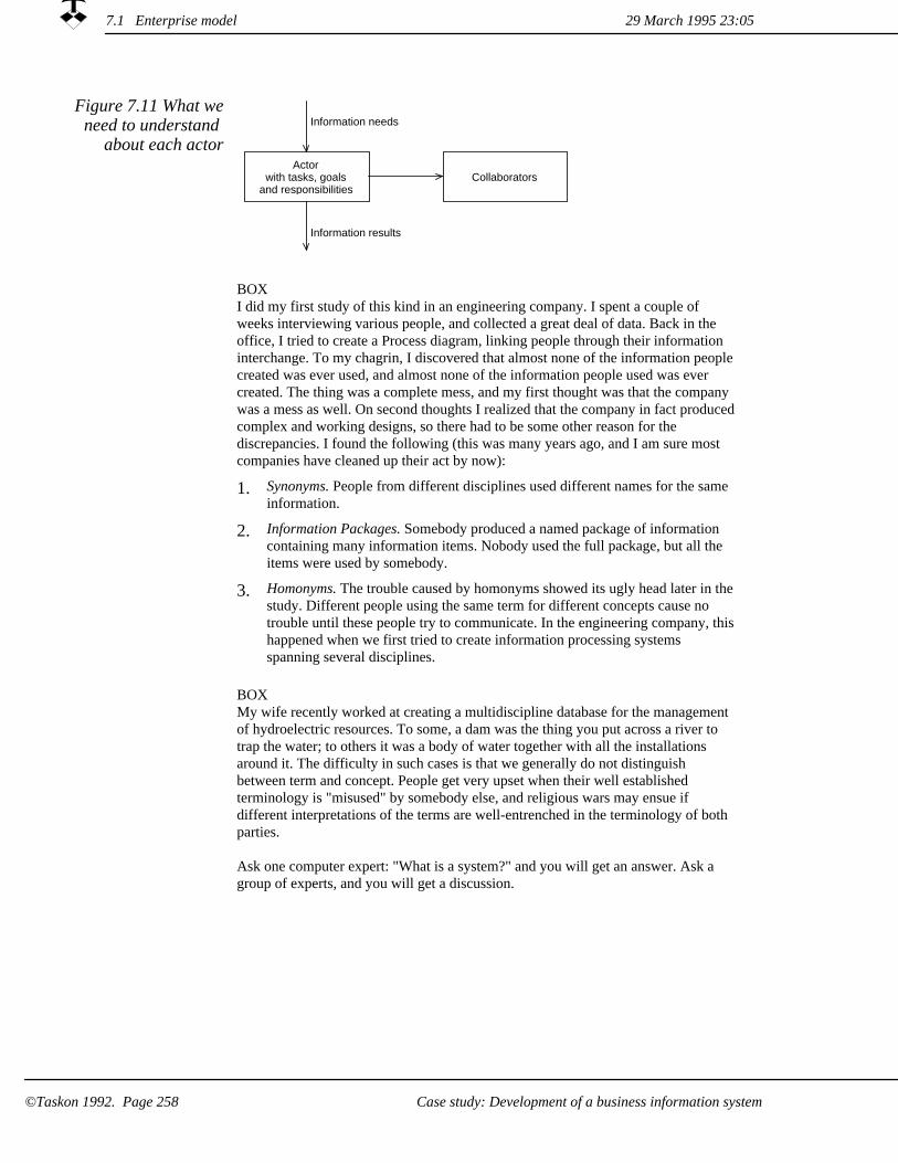
Figure 7.11 What weneed to understand
about each actor
Collaborators
Information results
Information needs
Actorwith tasks, goals
and responsibilities
BOXI did my first study of this kind in an engineering company. I spent a couple of weeks interviewing various people, and collected a great deal of data. Back in the office, I tried to create a Process diagram, linking people through their information interchange. To my chagrin, I discovered that almost none of the information peoplecreated was ever used, and almost none of the information people used was ever created. The thing was a complete mess, and my first thought was that the company was a mess as well. On second thoughts I realized that the company in fact producedcomplex and working designs, so there had to be some other reason for the discrepancies. I found the following (this was many years ago, and I am sure most companies have cleaned up their act by now):
1. Synonyms. People from different disciplines used different names for the same information.
Information Packages. Somebody produced a named package of information containing many information items. Nobody used the full package, but all the items were used by somebody.
2.
Homonyms. The trouble caused by homonyms showed its ugly head later in thestudy. Different people using the same term for different concepts cause no trouble until these people try to communicate. In the engineering company, thishappened when we first tried to create information processing systems spanning several disciplines.
3.
BOXMy wife recently worked at creating a multidiscipline database for the management of hydroelectric resources. To some, a dam was the thing you put across a river to trap the water; to others it was a body of water together with all the installations around it. The difficulty in such cases is that we generally do not distinguish between term and concept. People get very upset when their well established terminology is "misused" by somebody else, and religious wars may ensue if different interpretations of the terms are well-entrenched in the terminology of both parties.
Ask one computer expert: "What is a system?" and you will get an answer. Ask a group of experts, and you will get a discussion.
29 March 1995 23:057.1 Enterprise model
©Taskon 1992. Page 258 Case study: Development of a business information system

7.1.3 Determine environment roles and Stimulus/Response
An environment role is a role that triggers some activity in the system,or a role that receives a trigger for some unspecified activity in the environment. In our case, the Traveler takes an initiative; the cause of this initiative is outside the scope of this model. The Traveler is, therefore, an environment role. When the travel is completed and the travel expense report has been processed, the Paymaster is asked to arrange for reimbursement. This model does not describe how this is done; the Paymaster is therefore an environment role.
pment tr
ENTSystem<ENTTravelertravelPermissionRequest:
ENTTraveler
ENTPaymaster<ENTBookkeeperpaymentRequest:
ENTSystem
ENTPaymaster
Figure 7.12 Stimulus/Response
The stimulus messages and the corresponding system responses are conveniently presented as shown in figure 7.12. The system is shown as an unspecified cluster of roles called a virtual role. The system input and output ports are annotated with the stimulus and response messages.
7.1.4 Identify and understand the roles
It is customary in organization development to consider people's rolesin the enterprise processes. A person may play many roles, and a role may be played by several people. We want to create a role model of the travel expense report process. A role model is a stylized object model:
Identify object patterns. Identify a pattern of interacting objects and represent it as a corresponding pattern of interacting roles.
1.
29 March 1995 23:05 7.1 Enterprise model
©Taskon 1992. Page 259Case study: Development of a business information system

2. Suppress aspects irrelevant to the current topic, and only represent information about the objects that you choose to consider as relevant. In our example, we only consider travel accounts and suppress related phenomena such as budgeting and reimbursement.
3. Generalize object identity, and represent all objects serving the same purpose within the structure of objects as a single role. Think of this role as a typical object in the context of the area of concern. In our example, we let a Traveler role represent any person who travels, and an Authorizer role represent any person who authorizes a travel.
4. Suppress irrelevant detail, using the object encapsulation propertyto hide details that do not help you understand the phenomenon ofinterest. In our example, we focused on the overall aspects of the phenomenon and suppressed all the internal details such as the itinerary of the travel; or the procedure followed by the Authorizer to decide to OK an expense account.
In our example, we find that the role of Traveler may be played by any member of the staff. The role of Authorizer may be played by anymanager, and the roles of Bookkeeper and Paymaster are played by Bill and Joe. We will have to consider if objects may play multiple roles, and decide if it is OK for a manager to authorize his or her own travel. The result is formally recorded textually in a role/responsibilitylist as shown in figure 7.13.
Figure 7.13 The roles
role 'ENTTraveler' explanation "The person who travels"role 'ENTAuthorizer' explanation "The person who authorizes the travel."role 'ENTBookkeeper' explanation "The person responsible for bookkeeping."role 'ENTPaymaster' explanation "The person responsible for reimbursement."
We have here given the role definitions in textual form using extracts of the OOram language defined in Appendix A. We do not recommend a tabular form, because you should write as complete roledescriptions as possible.
Determine the Work Process7.1.5
Process Diagram shows sample data
flow with associated actions
Through conversation and observation, we build our understanding of the actors, their responsibilities, their collaborators and their information processes. We describe the work flow in a Process Diagram as illustrated in figure 7.14.
29 March 1995 23:057.1 Enterprise model
Case study: Development of a business information system©Taskon 1992. Page 260

ENTTraveler
ENTAuthorizer
ENTBookkeeper
ENTPaymaster
Desireto
travel
<Determine OK>
travelPermission
Request:
<Order tickets><Travel>
<Write exp.rep.>
travelPermission:
<Check OK>
expenseReport:
<Check><Bookkeeping>
authorizedExpenseReport:
<Arrange for payment>
paymentRequest:
Figure 7.14 ExpenseAccount
process view
In figure 7.14, the roles are represented as super-ellipses drawn at the top of the diagram. Rectangles are shown below the appropriate role symbol, they represent tasks performed by the roles. A text in <angle bracket> represents a pseudo-operation. Parallelograms represent datathat flow between the tasks. Data usually change ownership during the transfer and the column is irrelevant. The data flow follows the arrows connecting the symbols.
Postpone classification
The roles are archetypical objects idealized in the context of the current area of concern. High complexity or repeated patterns are warnings that sub-models should be factored out.
Data carried by messages between
objects
Objects can only interact through messages in our object model. Data must therefore be carried from one role to another as parameters to appropriate messages. If a role needs several data items before it can perform a task, the role must store the received data as attributes until all data have arrived and the task can be performed. (The message which finally releases the task is frequently called a trigger in the literature).
We have stipulated that a list of roles is documented before the description of the work processes. The list is usually best created as a by-product of describing the work processes, the two sections are thuscreated concurrently.
Iterate!
7.1 Enterprise model29 March 1995 23:05
Case study: Development of a business information system ©Taskon 1992. Page 261

Determine the Collaboration Structure7.1.6
Based on the information in the Process Diagrams and our general understanding of the work processes, we draw a Role Collaboration View as shown in figure 7.15.
Figure 7.15 Role Collaboration View
for the travel expenseprocess
au tr
pm
bo
ENTTraveler
ENTAuthorizer
ENTBookkeeper
ENTPaymaster
The Collaboration View may be annotated with role descriptions as illustrated in figure 7.16.
Figure 7.16 Role Collaboration View annotated with role
descriptions
pm
bo
au trENTTraveler
ENTAuthorizer
The person who travels.
ENTBookkeeper
The person who authorizes the travel.
The person responsible for bookkeeping.
ENTPaymaster
The person responsible for reimbursement.
7.1.7 Determine Interfaces
Associate a list of all the messages that a role may send to a collaborator with the corresponding port. A Process View shows an example process, the interfaces must include all messages shown in these views. Study the resulting interfaces, and add messages that seem to be missing to make them nicely rounded representations of the role functionality.
Determine the messages that may be sent from each
port
7.1 Enterprise model 29 March 1995 23:05
©Taskon 1992. Page 262 Case study: Development of a business information system

Figure 7.17 Role Collaboration View
annotated with message interfaces
bo
pm
au trENTTraveler
ENTTraveler<ENTAuthorizertravelPermission: aTravelPermission
ENTAuthorizer<ENTTravelerexpenseReport: anExpenseReporttravelPermissionRequest: aTravelPermission
ENTBookkeeper<ENTAuthorizerauthorizedExpenseReport: anExpenseReport
ENTPaymaster<ENTBookkeeperpaymentRequest: aPaymentRequest
ENTAuthorizer
ENTBookkeeper
ENTPaymaster
The Role Collaboration view can be annotated with the permitted messages as illustrated in figure 7.17. The interfaces are often too large to conveniently fit onto the diagram, or you may want to describe more details about message parameters and their types. You then describe the interfaces textually as shown in figure 7.18. The language is an extract of the OOram language described in appendix A.
Two interface notations
Figure 7.18 Interfaces for the
Enterprise model in informal textual form
interface 'ENTAuthorizer<ENTTraveler' /* Read as "ENTAuthorizer from ENTTraveler" */
message synch 'travelPermissionRequest:' explanation "Request authorization of submitted travel plan."param 'aTravelPermission' type 'INFTravelPermission' :: 'Travel Expense
Information Model'message synch 'expenseReport:'
explanation "Request reimbursement of submitted expense report."param 'anExpenseReport' type 'INFExpenseAccount' :: 'Travel Expense
Information Model'interface 'ENTTraveler<ENTAuthorizer'
message 'travelPermission:' explanation "Travel authorization granted."param 'aTravelPermission' type 'INFTravelPermission' :: 'Travel Expense
Information Model'interface 'ENTBookkeeper<ENTAuthorizer'
message synch 'authorizedExpenseReport:' explanation "Request reimbursement of submitted expense report."param 'anExpenseReport' type 'INFExpenseAccount' :: 'Travel Expense
Information Model'interface 'ENTPaymaster<ENTBookkeeper'
message 'paymentRequest:' explanation "Reimburse the specified account."param 'aPaymentRequest' type 'INFPayRequest' :: 'Travel Expense
Information Model'
29 March 1995 23:05 7.1 Enterprise model
Case study: Development of a business information system ©Taskon 1992. Page 263

The OOram language interface specification can optionally include the parameter types. The specification in figure 7.18 is particularly interesting because the parameters define relations between this model and the information model. The parameter of the first message must for example reference an object which plays the INFTravelPermission role in the Travel Expense Information Model.
29 March 1995 23:057.1 Enterprise model
Case study: Development of a business information system©Taskon 1992. Page 264

7.2 Information model
In a nutshellThe enterprise model described what people do to achieve a certain purpose. It also described the information that was the subject of the messages, but it did not define the information semantics or representation. We will now create a detailed model ofthis information.
First iteration Information model
derived from Enterprise model
The Information model describes the universe of discourse of the Enterprise model; i.e. its message parameters and role attributes.
You begin by listing all relevant parameters and attributes in the enterprise model. Then define an Information model role for each of them and determine the relationships between them. Extend it into a complete model of the world of information as it is perceived by the user community.
You will need to choose an appropriate modeling paradigm; choose a relational database if a passive data repository is satisfactory, choose an object-oriented database if data behavior is an essential part of the information model.
Some information may be handled informally, either orally or throughinformal media such as memos or electronic mail. Travel permissions are frequently handled this way. The travel expense report itself is frequently required to be on a formal business form or data record. It contains fields for the different kinds of information:
Some information may be handled
manually
1. Traveler's name and ID
2. Purpose of travel
Authorizer name and ID3.
4. Permission date
Itemized specification of expenses5.
6. Gross amount
Advance payment7.
8. Net amount
Authorization date9.
29 March 1995 23:05 7.2 Information model
Case study: Development of a business information system ©Taskon 1992. Page 265

An early decision is to choose the information that will be representedin an information system and concentrate further work on this subset. Our choice is to focus on the ExpenseAccount itself.
Focus on computer-based information
We will now develop a model of the ExpenseAccount information. Our suggested information modeling process consists of creating the views listed below. This is just one of the many possibilities, and you will have to develop your own process to suit your own circumstances. And as usual, your work process will be iterative even if your documentation has to be sequential.
Creating the information model
1. Area of concern -- the scope of the information model
2. Semantic view -- also the foundation of a possible relational model
3. Role list view -- the information entities and their attributes
Collaboration view -- showing the data structure4.
Interface view -- definition of desired behavior5.
The Semantic view is most relevant when we consider the Informationmodel in conjunction with the Enterprise model. Behavior will be added later to enable the Information model to respond to requests from the tools that are described in section 7.3. The main iterations arethus between Enterprise model and the Semantic view of the Information model, and between the Task/Tool/Service model and thecollaboration view of the Information model.
7.2.1 Area of concern
The area of concern shown in figure 7.19 reflects our change of focus from enterprise to information.
Figure 7.19 Area of Concern
The area of concern is modeling the information contained in travel expense accounts. We focus on the expense account itself and do not model details about the input and output in the user interfaces.
7.2 Information model 29 March 1995 23:05
Case study: Development of a business information system©Taskon 1992. Page 266

Semantic view7.2.2
We will encounter a number of information concepts when we interview users and build the enterprise model. It is a good idea to create and maintain a Semantic view on this information to help us understand the phenomena under study and to establish the precision and consistency needed for automatic data processing purposes. Figure 7.20 shows a semantic view of the information model.
consists_of
part_of
consists_of
part_of
consists_of
part_of
ExpenseAccount
travellerpurpose
start_dateend_dateadvance
Permission
dateauthorizer
Authorization
dateauthorizer
ExpenseItem
datetext
amount
Figure 7.20 Semanticview of Information
model
7.2.3 Role list view
The roles are derived from the Semantic view and optionally elaborated with attribute information. The diagram in figure 7.20 mayalso be annotated with the role semantics, but it is usually better to describe the list textually as shown in figure 7.21. We have elected to omit the attribute type specification, this is optional according to the OOram language defined in appendix A.
29 March 1995 23:05 7.2 Information model
©Taskon 1992. Page 267Case study: Development of a business information system

Figure 7.21 The roles of the
Information model
role 'ExpenseAccount' explanation "The master object representing an expense account."attribute 'traveler'attribute 'purpose'attribute 'start_date'attribute 'end_date'attribute 'advance'
role 'ExpenseItem' explanation "A specified cost."attribute 'date'attribute 'text'attribute 'amount'
role 'Permission' explanation "A permission to travel."attribute 'date'attribute 'authorizer'
role 'Authorization' explanation "A disbursement order."attribute 'date'attribute 'authorizer'
We usually postpone the formal typing of the attributes to a later stagein the process, but we may include type information here when it is known.
A hybrid solution with a relational database7.2.4
The relational database technology is a mature technology, and ideallysuited for the storage and retrieval of simple data records. We recommend that you use it wherever it is applicable.
For example, most of the expense account information will ultimately end up in the accounting department's data processing system. The enterprise may simplify its archiving function and save some paper shuffling, if the traveler could enter the account data directly into the system, and the authorizer could read the account on a screen and authorize it by a keystroke.
A database may improve the
management of travel accounts
The design of a relational database for storing expense accounts can be done by any of the popular database design methodologies. One possible structure is indicated in figure 7.22.
29 March 1995 23:057.2 Information model
©Taskon 1992. Page 268 Case study: Development of a business information system

Figure 7.22 Possible structure of
relational information model
Expense_Account tableexpense_account_idtraveler_employee_idtravel_purposedate_travel_startdate_travel_endauthorizer_employee_idpermission_dateauthorization_dateadvance
Employee tableemployee_idemployee_namedepartment_id
Expense_Item tableexpense_account_iditem_numberdateitem_textitem_amount
To those of us who never get the sums right, the expense account maybe drafted in a spreadsheet. An even better solution would be a specialexpense account program which could help us fill in the different items, convert foreign expenses into our local currency, do the sums, and provide on line information about the latest rules, regulations and rates.
A personal assistant may improve the
creation of travel accounts
If the authorities insist that the accounts shall be submitted on the approved form, we could transcribe the spreadsheet results manually (as I had to do at my former employer). But we will discuss a better solution, where we use objects to combine the behavior of the personal assistant with the data storage capabilities of the relational database. Object-oriented, direct manipulation user interfaces will be discussed in section 7.3. They may be designed to print the official paper forms, to interact with relational databases, or to provide the interface between a user and an object-oriented domain service.
A relational database may be accessed from a program through what is known as an 'Application Programming Interface' (API). We can define objects with the message interface of our choice, and define thenecessary methods to convert these messages to the appropriate API calls on the database.
The simplest and most general is to define a message interface which essentially offers an SQL service. This is illustrated in figure 7.23 (a). A more sophisticated solution is to add an intermediate layer which offers a message interface relating to ExpenseAccount concepts as illustrated in figure 7.23 (b). The latter solution is more robust, because it isolates the database, its schema and constraints from the tool objects.
Hybrid solution: An object can
encapsulate a relational database
7.2 Information model29 March 1995 23:05
©Taskon 1992. Page 269Case study: Development of a business information system

(a) (b)
User interface tool
Object encapsulatingSQL calls on a
relational database
SQLmessages
User interface tool
Object encapsulatingSQL calls on a
relational database
ExpenseAccount
ExpenseAccountmessages
SQLmessages
Figure 7.23 Objects may encapsulate a relational database
Collaboration view7.2.5
Figure 7.24 shows a first iteration of the collaboration view of the Information model. It is structurally similar to figure 7.20, but the lines of the semantic view denote conceptual relationships while the lines of the collaboration view denote role accessibility and collaboration.
tp
ea
ei
ea
pa
ea
ExpenseAccount
Permission AuthorizationDate ExpenseItem
Figure 7.24 Information model Collaboration view
Interface view7.2.6
Interface definitions The main behavior requirements for the Information model will be derived from the Task/Tool/Service models to be discussed in the nextsection. We may also want to add behavior associated with our travel expense regulations so that the system can provide default values and check against maximum values for different kinds of expenditure.
7.2 Information model 29 March 1995 23:05
Case study: Development of a business information system©Taskon 1992. Page 270

We do not discuss the detailed analysis of the Information model behavior here; the work follows the same process as the analysis of the Enterprise model and you would actually be well advised to analyze both models simultaneously.
29 March 1995 23:05 7.2 Information model
Case study: Development of a business information system ©Taskon 1992. Page 271
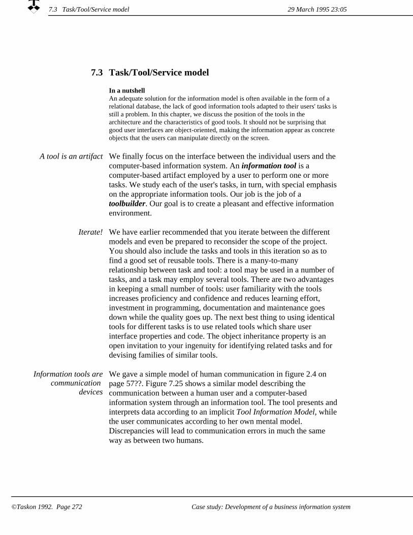
Task/Tool/Service model7.3
In a nutshellAn adequate solution for the information model is often available in the form of a relational database, the lack of good information tools adapted to their users' tasks isstill a problem. In this chapter, we discuss the position of the tools in the architecture and the characteristics of good tools. It should not be surprising that good user interfaces are object-oriented, making the information appear as concrete objects that the users can manipulate directly on the screen.
A tool is an artifact We finally focus on the interface between the individual users and the computer-based information system. An information tool is a computer-based artifact employed by a user to perform one or more tasks. We study each of the user's tasks, in turn, with special emphasison the appropriate information tools. Our job is the job of a toolbuilder. Our goal is to create a pleasant and effective information environment.
We have earlier recommended that you iterate between the different models and even be prepared to reconsider the scope of the project. You should also include the tasks and tools in this iteration so as to find a good set of reusable tools. There is a many-to-many relationship between task and tool: a tool may be used in a number of tasks, and a task may employ several tools. There are two advantages in keeping a small number of tools: user familiarity with the tools increases proficiency and confidence and reduces learning effort, investment in programming, documentation and maintenance goes down while the quality goes up. The next best thing to using identical tools for different tasks is to use related tools which share user interface properties and code. The object inheritance property is an open invitation to your ingenuity for identifying related tasks and for devising families of similar tools.
Iterate!
We gave a simple model of human communication in figure 2.4 on page 57??. Figure 7.25 shows a similar model describing the communication between a human user and a computer-based information system through an information tool. The tool presents andinterprets data according to an implicit Tool Information Model, whilethe user communicates according to her own mental model. Discrepancies will lead to communication errors in much the same way as between two humans.
Information tools arecommunication
devices
7.3 Task/Tool/Service model 29 March 1995 23:05
Case study: Development of a business information system©Taskon 1992. Page 272

Task
Domain ServiceTool
Mental tool model
ServiceInformation model
ToolInformation model
Figure 7.25 A personcommunicates with
one or more computer-based
Domain Services through a Tool
The user has a mental model of the information handled in the task. The information system is based on an (object-oriented) information model that frequently is different from the user's model in scope, complexity and precision. An important success criterion for a tool is that it provides the required filtering and translation so that the user gets the illusion of working with a system that supports the user's mental model of the information.
The three schema architecture of database systems serves this purpose: An external schema is tailored to the needs of particular users and provides a filtered view of the conceptual schema defining the information contents of the database. The third schema is the implementation schema, which defines how the information is actually stored in the computer. Object orientation gives us added freedom when defining the external schemas: algorithms in the tools can translate the concepts of the service information model into concepts more familiar to the user.
BOXWe have earlier described a situation concerning hydroelectric resource management, where two disciplines used the term dam to mean different things. Two solutions to this dilemma are open to the systems designer: we can force the disciplines to harmonize their terminology, or we can create tools that do the necessary translations so that the disciplines can retain their favorite terminology. Our technology permits both solutions. It is a management decision to select the onethat best serves the needs of the enterprise.
7.3.1 Creating Task/Tool/Service descriptions
Create task and tool descriptions
The tasks are extracted from the process diagrams such as the example in figure 7.14. We now create a detailed task description as aprecursor to designing a tool. The task description could consist of thefollowing:
7.3 Task/Tool/Service model29 March 1995 23:05
©Taskon 1992. Page 273Case study: Development of a business information system

1. Scope and Goal of the task.
User work situation, describing the task in the context of the user's overall work situation. Task frequency and perceived importance are particularly relevant since they determine the amount of specialized tool training that can be assumed.
2.
Input information needed to perform the task.3.
Trigger that releases the task.4.
Output information that results from the task.5.
Tool description that specifies the tool to be used.6.
7. Task Scenario narrative that describes how the task will be performed.
The tasks of our ExpenseAccount example are shown in the Process view of the enterprise model in figure 7.14. The tasks are as follows:
The tasks of our ExpenseAccount
example
1. The Traveler role:
Prepare travel authorization request.¤Prepare travel expense account.¤
The Authorizer role:2.
¤ Process travel request and post answer.Check and forward expense account.¤
The Bookkeeper role:3.
Check expense account, record accounts, authorize payment.¤
The Paymaster role:4.
Record amount to be added to next payment of salary.¤
We will now study possible tools to be used by the Authorizer for performing her task. This tool will be part of a personal information environment for persons playing the Authorizer role in the organization. We will describe two alternative tools. The common parts of the task descriptions are as follows:
Example task description:
Authorizer process travel request
29 March 1995 23:057.3 Task/Tool/Service model
Case study: Development of a business information system©Taskon 1992. Page 274

1. Scope and Goal. The goal of this task is to determine if the proposed travel shall be permitted. The Authorizer should estimate the value of this travel to the enterprise and check if the trip conforms to current plans. The Authorizer should also consider if funds are available in the budget for the proposed travel, and possibly arrange for additional funds if the situation warrants it.
User work situation. This task is but one of the numerous administrative tasks performed by persons playing the Authorizer role. In this case, it should be possible to perform it as a simple routine in a few minutes, and the training needed to master the tools should be minimal.
2.
Input information needed to perform the task is the travel request itself. Possible information items that could be useful to the Authorizer are: the purpose of the journey, when it will take place, and the planned total cost. The Authorizer could also need access to the work plans for the indicated time period, to the budget and to accounts showing current commitments.
3.
Trigger. We assume that the Authorizer's information environment includes a task management facility. This task will then be added to the Authorizer's list of outstanding tasks so that she can select it for execution at her convenience. Since this task is but one of a large number of similar tasks, it is important that she shall not be required to spend any mental energy relating to this task outside the few minutes it takes to process it.
4.
Output information. The authorization or rejection shall be passedto the Traveler. This information shall also be stored and be retrieved automatically if and when the Authorizer receives an expense account for processing.
5.
6. Tool description. We will discuss two alternatives below.
Task Scenario. A first description is given under Scope and Goal above. More detailed scenarios will be given below.
7.
7.3 Task/Tool/Service model29 March 1995 23:05
©Taskon 1992. Page 275Case study: Development of a business information system
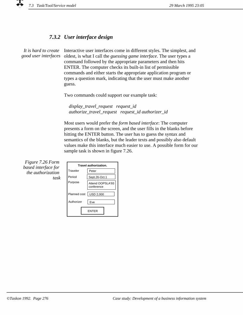
User interface design7.3.2
Interactive user interfaces come in different styles. The simplest, and oldest, is what I call the guessing game interface. The user types a command followed by the appropriate parameters and then hits ENTER. The computer checks its built-in list of permissible commands and either starts the appropriate application program or types a question mark, indicating that the user must make another guess.
It is hard to create good user interfaces
Two commands could support our example task:
display_travel_request request_idauthorize_travel_request request_id authorizer_id
Most users would prefer the form based interface: The computer presents a form on the screen, and the user fills in the blanks before hitting the ENTER button. The user has to guess the syntax and semantics of the blanks, but the leader texts and possibly also default values make this interface much easier to use. A possible form for our sample task is shown in figure 7.26.
Figure 7.26 Form based interface for
the authorization task
Travel authorization.
USD 2,000Planned cost
Authorizer
Attend OOPSLA'93conference
Purpose
Sept.26-Oct.1Period
PeterTraveler
ENTER
Eve
7.3 Task/Tool/Service model 29 March 1995 23:05
©Taskon 1992. Page 276 Case study: Development of a business information system
The goal of the object-oriented, direct manipulation interface is to provide a visual presentation of the information in intuitive and "obvious" manner and reflect a part of the user's mental model. The interface should permit the user to manipulate this information in the simplest way possible in accordance with the user's goals and tasks. Information is essentially an abstract notion. To my mind, the essential property of object-oriented, direct manipulation user interfaces is that they make the information appear concrete: something the user can see, manipulate and interact with. The following suggestions for good user interface design are adapted from a series of lectures presented by Bruce Horn to graduate students at the University of Oslo, Norway. These rules constitute the best adviceI have ever seen on the subject. They appear here in print for the first time with the permission of Bruce Horn and our gratitude:
Making information appear concrete
Design and Implementation Must Feed Back. The creation of userinterfaces is a highly subjective endeavor, and I almost never get it right the first time. I therefore suggest that you create a prototype. Try it out yourself and let the users try it, improve it, and try it out again. Your empathy with the user is crucial. If you create a tool for a rote operation, the user may prefer a simple toolthat leads him or her through a series of fixed steps. If you create a tool for a task requiring intelligence and creativity, the user mayprefer a tool which makes the computer augment his intelligence. Use your own software in your own work if it is at all feasible. Your knowledge about its structure is likely to give ideas for improvement which would never occur to others.
1.
The Principle of Least Astonishment. The behavior of the system must follow the expectations of the users. Any exclamation of astonishment from a user must be considered a warning of poor design.
2.
See and Point vs. Remember and Type. It is much easier to reference something you can see, via pointing, than to remember the name of something and type. This is the essence of direct manipulation: making the computer invisible -- an extension of yourself -- you point at an object and ask it to do something. Of course, not everything will (or should) have a name, so being ableto see something and point at it may be the only way to specify it. In addition, one can select a group of objects to choose from by describing them by analogy or by using a search specification, and then choosing the desired object by pointing.
3.
7.3 Task/Tool/Service model29 March 1995 23:05
©Taskon 1992. Page 277Case study: Development of a business information system

No Modes. Of course, computers do have modes. Modes are just contexts in which the previous actions of the user change the meaning of current actions. However, these modes, in order to be acceptable, must be either spring-loaded such as a key or a button, or must be metaphorical such as a paint tool. Modes are also acceptable when they are made apparent to the user, such as a cursor changing to a tool, or a window or pane that provides a particular modal function (drawing or text editing panes, for example).
4.
Maintain User Illusion of Direct Manipulation. Maintaining this illusion is extremely important, and it affects decisions regarding implementation. It is critical that the attention of the user is focused on the computer's results. The user-computer circuit is the information flow from the user to the computer, and back again to the user. This circuit is what is maintained when the user is engaged and attending to the objects presented by the user interface.
5.
Performance is critical. If operations are too slow, the person is likely to wander off and break the circuit. Then we have theproblem of the user rebuilding the contents of her short-term memory ("where was I?").
*
Maintain Closure. With good performance in critical areas, we can maintain closure. Each operation is a closeable, atomic operation, such that the user need not remember partial state. With small, atomic operations it is not necessary to provide a facility for interrupting the operation because the operation is self-contained, and the operation's length is short enough to maintain the user's attention.
*
* Immediate feedback. The illusion of information as concrete objects is enhanced by immediate feedback and suitable animation. You may, for example, highlight legal menu and palette operations in each context; animate spatial relationships such as windows opening and closing; and showprogress in long operations such as printing.
29 March 1995 23:057.3 Task/Tool/Service model
©Taskon 1992. Page 278 Case study: Development of a business information system

6. Handle Errors Gracefully. The best approach is to design the interface so as to avoid possible error situations. Typing errors areavoided entirely if the user selects a visible object rather than typing its name, and if she selects a menu command rather than types text to a command line interpreter. Illegal menu commands should be disabled before the menu is opened. Unnecessary program restrictions such as limited data buffer sizes should be avoided. (A wise man once said that there are only three good numbers in data processing: none, one, and all.)
If an error situation does occur, make sure you describe the error in user terms and explain what the user can do to take care of the problem.
7. Support Undo. Undo is perhaps the most useful function in a direct manipulation user interface because it allows experimentation, helps the user get out of dangerous situations, and helps support a positive mental attitude in the user since it permits the user to change her mind.
Provide a Help System. When all else fails, it is important to allow the user to find the information needed on-line, integrated with the system, rather than forcing her to read the manual. A help system can answer questions such as What is..., How do I..., What just happened... and Why was that an error?
8.
9. Be Creative. Designing a user interface is a creative activity. It requires being able to look at several points of view simultaneously, and to try out conceptual ideas quickly. Creativity springs from rigor and imagination applied alternately: imaginative thought to create possible ideas, applied rigorously tothe problem at hand to determine their suitability. "Rigor alone is paralytic death, while imagination alone is insanity." (Bateson)
...and above all, have fun.
7.3.3 A simple direct manipulation interface for our task example
When we created the Enterprise Model in the previous section, we permitted ourselves to isolate travel expense account processing from all other processes taking place in the enterprise. The above task
7.3 Task/Tool/Service model29 March 1995 23:05
Case study: Development of a business information system ©Taskon 1992. Page 279

description tells us that this is a luxury we cannot afford when we consider the performance of its tasks. When the Authorizer processes a travel request, she has to consider three separate functions: expense account processing, budget and accounts, and the planning function.
The simplest solution from the programmer's point of view is to require the Authorizer to open three distinct and independent tools: a tool on budget and accounts, a tool on current plans, and a tool on the travel expense account. She can then perform the task as described under Scope and Goals, transcribing information such as planned totalcost from one tool to another as required. A possible set of tools are sketched out in figure 7.27.
EveElsiePeterKim
Week 35 36 37 38 39 40 41
Project 1OOPSLAProject 3Project 4
Current plans for Software Department
Budget and commitmentsSoftware Department
ItemEquipmentSoftwareTravelConsultantsPersonnel
Committed12,14832,765
4,00063,987
190,000
Peter to OOPSLAValueText
Add Commitment
2,000
Budget50,00065,00010,00085,000
200,000
Travel permission.
USD 2,000Planned cost
Authorize
Attend OOPSLA'93conference
Purpose
Sept.26-Oct.1Period
PeterTraveler
Reject
Figure 7.27 Three distinct tools to serve
the authorization task
A possible scenario using these tools is as follows:
1. Open Travel Permission Request tool on a current permission request data set according to the rules of your information environment. (e.g., point to a visual representation of the data set and give an open-command).
2. Check the travel request purpose and determine that it is a reasonable request.
29 March 1995 23:057.3 Task/Tool/Service model
Case study: Development of a business information system©Taskon 1992. Page 280

Open the Budget and commitments tool and the Current Plans tool. This may be done according to the relevant user manuals. Alternatively, the Personal Task manager could be part of a sophisticated process control system and provide direct access to these tools as described in a definition of the process.
3.
4. Check the Current Plans, and modify them if necessary to accommodate the proposed travel.
Check the budget and secure additional appropriations if necessary. Select the appropriate budget item and record the commitment.
5.
Press the Authorize button in the Travel Authorization Request tool to transmit and record the travelPermission.
6.
7.3.4 A composite user interface for the manager to determine travel permission
The tools described above were not integrated for the current task. The Authorizer had to select corresponding items in the different tools, create a new budget commitment and copy the amount from theTravelRequest into it.
We could consider creating a specialized tool for the travel authorization task. The decision to do so would depend on the potential savings and the cost of its creation. Automated aids such as VisualWorks from ParcPlace Systems makes it easy to create specialized tools, and future aids may well make it feasible for the users to create their own personal tools.
We will sketch out a possible tool in figure 7.28 to illustrate the idea. A real life tool would have to be based on a detailed study of the tasks, and should probably be more sophisticated.
29 March 1995 23:05 7.3 Task/Tool/Service model
©Taskon 1992. Page 281Case study: Development of a business information system

Travel permission request.
Permit
Attend OOPSLA'93 conferencePurpose
USD 2,000Planned costPeterTraveler Sept.26-Oct.1Period
Current plans for Peter
Week 35 36 37 38 39 40 41
Project 1OOPSLAProject 3Project 4
Budget and commitments
ItemTravel
Committed4,000
Budget10,000
Reject
Figure 7.28 A simpletool integrated for
the Travel Permission task
A possible scenario using this tool is as follows:
Open the specialized Travel permission request tool on a current permission request data set according to the rules of your information environment. (e.g., point to a visual representation of the data set and give an open-command).
1.
Check the travel request purpose and determine that it is a reasonable request.
2.
3. The appropriate budget and commitments items are automatically selected and displayed. Check them. A menu command opens a separate tool if corrective action is necessary.
4. The appropriate portion of the plans for the Traveler is automatically displayed. Check it. A menu command opens a separate tool if corrective action is necessary.
Check the budget and secure additional funds if necessary. Select the appropriate budget item and record the commitment.
5.
Press the Permit button in the Travel Permission tool to transmit and record the travelPermission and to record the budget commitment.
6.
This single tool will be sufficient for most practical cases, and is clearly superior to the hodgepodge of windows needed in the previoussolution. Note that this is an example of integration on level 3 in figure 7.5. The separation between different Information services, which is so useful for the information processing department, is uninteresting from the users point of view and is hidden.
We will now create a role model of the tool shown in figure 7.28. We begin with the area of concern in figure 7.29.
29 March 1995 23:057.3 Task/Tool/Service model
Case study: Development of a business information system©Taskon 1992. Page 282

Figure 7.29 Area of concern
The area of concern is an integrated tool for the authorization of a travel proposal in our enterprise
The roles are specified in figure 7.30 using the OOram language syntax defined in appendix A. The Authorizer is the role representing any person who authorizes a travel. We let a single role, Trav.Auth.Tool, represent the clusters of objects that implement the tool. This tool is a nice illustration of the two-dimensional nature of our architecture. It is an integrated tool that accesses three services. We represent each of them as a single role: an ExpenseAccountService, a PlanningService and a BudgetService. TheExpenseAccountService is the service described by the Information model in section 7.2. The description of the other services are left open to your imagination.
Figure 7.30 The roles
role 'TSAuthorizer' explanation "The person who authorizes the travel."role 'TSAuthorizerTool' explanation "The user interface system"role 'TSAccountService' explanation "An object structure representing a particular expense account."role 'TSPlanningService' explanation "A system representing the current plans for the enterprise"role 'TSBudgetService' explanation "A system managing the enterprise budget"
We recognize that the tool and the service roles may be virtual, they will then be expanded into clusters of roles in a later stage of the development.
We create two Process diagrams: One for the opening of the tool shown in figure 7.31, and another describing a typical sequence of events when the Authorizer hits the Permit-button shown in figure 7.32.
29 March 1995 23:05 7.3 Task/Tool/Service model
©Taskon 1992. Page 283Case study: Development of a business information system

TSAuthorizer
TSAuthorizer
Tool
TSAccountService
TSBudgetService
TSPlanningService
Start authorization
activityCreate and open
travel authorization
tool
getExpenseAccount
ISExpenseAccount
getBudgetFor:
Budgetamount
getPlanFor:
Plan
Figure 7.31 Process diagram: Open
travel permission tool
TSAuthorizer
TSAuthorizer
Tool
TSAccountService
TSBudgetService
PressPermit-button
GrantPermission
putAuthorized:= true
true
Record newcommitment
Number
Figure 7.32 Process diagram: Grant
travel permission
The top level collaboration view of figure 7.33 follows directly from the basic tool model in figure 7.25.
7.3 Task/Tool/Service model 29 March 1995 23:05
Case study: Development of a business information system©Taskon 1992. Page 284

pla
acc
bud
tool authTSAuthorizer
TSAuthorizer
Tool
The person who authorizes the travel.
The user interface system.
TSAccountService
TSPlanningService
An object structure representing a particular expense account.
A system representing the current plans for the enterprise.
TSBudgetService
A system managing the enterprise budget.
Figure 7.33 InterfaceCollaboration View annotated with role
responsibilities
The stimulus messages are the available user commands; and each stimulus triggers an activity. We do not go into the detailed design of these activities here, but indicate a likely set of typical message interfaces. They are shown graphically in figure 7.34. We see that the diagram gets overloaded even in this simple example. The textual interface definition shown in figure 7.35 is better, and it also invites the analyst to explain the message semantics. (Note that parameter typing is optional, and that we have included parameter types in this informal specification.)
acc
bud
tool auth
pla
TSAuthorizer
TSBudgetService<TSAuthorizerToolcommit: amount for: kindgetBudgetFor: kind
TSAuthorizerTool<TSAuthorizeropenOn: expAccPermitReject
TSAuthorizer<TSAuthorizerTooldisplay
TSPlanningService<TSAuthorizerToolgetPlanFor: person
TSAccountService<TSAuthorizerToolgetExpenseAccountgetPeriodgetPlannedCostgetPurposeputAuthorized: aBoolean
TSAuthorizer
Tool
TSAccountService
TSPlanningService
TSBudgetService
Figure 7.34 InterfaceCollaboration View
annotated with Interfaces
29 March 1995 23:05 7.3 Task/Tool/Service model
©Taskon 1992. Page 285Case study: Development of a business information system
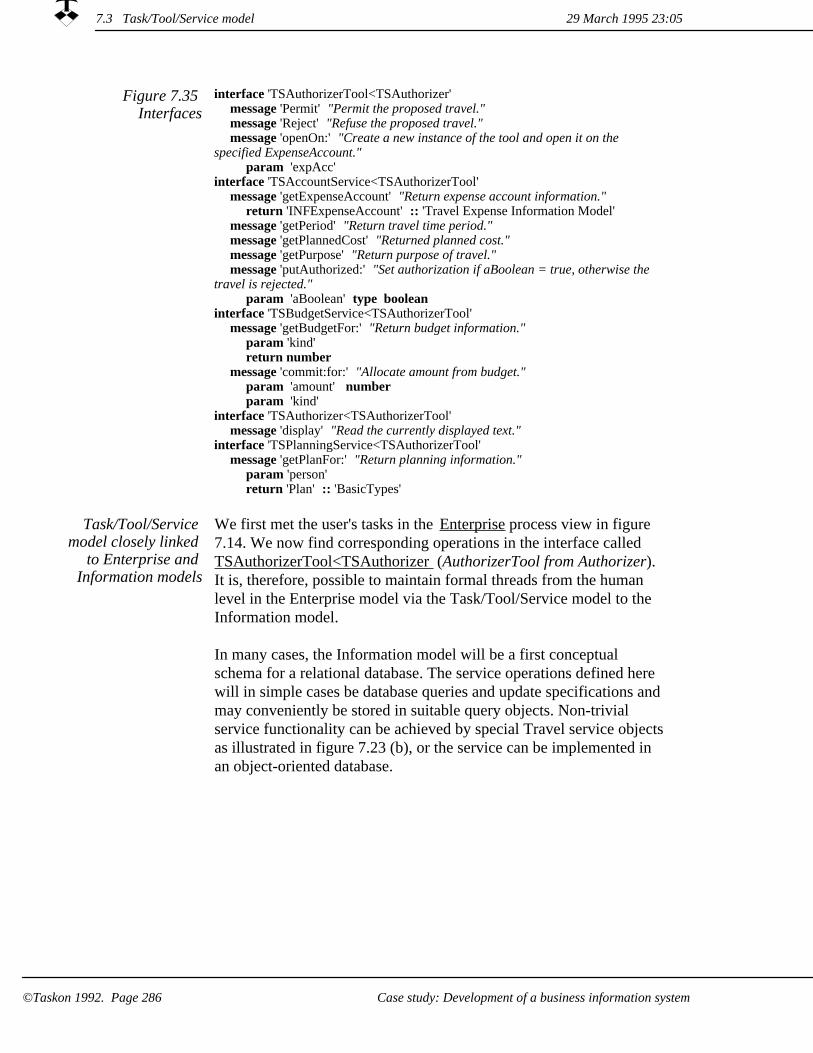
Figure 7.35 Interfaces
interface 'TSAuthorizerTool<TSAuthorizer' message 'Permit' "Permit the proposed travel."message 'Reject' "Refuse the proposed travel."message 'openOn:' "Create a new instance of the tool and open it on the
specified ExpenseAccount."param 'expAcc'
interface 'TSAccountService<TSAuthorizerTool' message 'getExpenseAccount' "Return expense account information."
return 'INFExpenseAccount' :: 'Travel Expense Information Model'message 'getPeriod' "Return travel time period."message 'getPlannedCost' "Returned planned cost."message 'getPurpose' "Return purpose of travel."message 'putAuthorized:' "Set authorization if aBoolean = true, otherwise the
travel is rejected."param 'aBoolean' type boolean
interface 'TSBudgetService<TSAuthorizerTool' message 'getBudgetFor:' "Return budget information."
param 'kind'return number
message 'commit:for:' "Allocate amount from budget."param 'amount' number param 'kind'
interface 'TSAuthorizer<TSAuthorizerTool' message 'display' "Read the currently displayed text."
interface 'TSPlanningService<TSAuthorizerTool' message 'getPlanFor:' "Return planning information."
param 'person'return 'Plan' :: 'BasicTypes'
We first met the user's tasks in the Enterprise process view in figure 7.14. We now find corresponding operations in the interface called TSAuthorizerTool<TSAuthorizer (AuthorizerTool from Authorizer). It is, therefore, possible to maintain formal threads from the human level in the Enterprise model via the Task/Tool/Service model to the Information model.
In many cases, the Information model will be a first conceptual schema for a relational database. The service operations defined here will in simple cases be database queries and update specifications and may conveniently be stored in suitable query objects. Non-trivial service functionality can be achieved by special Travel service objectsas illustrated in figure 7.23 (b), or the service can be implemented in an object-oriented database.
Task/Tool/Service model closely linked
to Enterprise and Information models
29 March 1995 23:057.3 Task/Tool/Service model
©Taskon 1992. Page 286 Case study: Development of a business information system

Chapter 8Case study: The analysis and design of a
real time system
This chapter is written for the specially interested programmer. It exemplifies the use of state diagrams. It also illustrates that role models are independent of implementation by showing the transition from the models to traditional and distributed implementation environments.
Determine area of concernDetermine area of concernIdentify environment roles and stimulus-responseDetermine typical message sequences
Detailed modelSpecify and understand objects and rolesDetermine typical message sequencesDescribe roles as state diagramsDetermine interfaces
Implementation examplesBridge to C++ Bridge to SmalltalkBridge to SDLBridge to Distributed object systemsOOram executable specifications
29 March 1995 23:05
©Taskon 1992. Page 287Case study: The analysis and design of a real time system

We will now study a case where the information is simple, but where we have to ensure that the system behaves properly in all circumstances. The case we have chosen is a real time access control system where a person identifies himself through a card and code reader, and the system unlocks the door if the person is granted access. The example has been inspired from a similar case in [Bræk 93].
Work process includes precise
modeling of behavior
Our suggested design process for solving the access control problem includes the specification of state diagrams to reflect our focus on behavior. There is a state diagram for each role; they are mutually dependent and must be consistent. The descriptions tend to be large and hard to modify, so we postpone the specification of the state diagrams to a late stage in the design process. A scenario is simpler than a set of state diagrams because it only shows the message sequences of a typical or critical case. We use scenarios in the early iterations to keep the volume of the model small, and add state diagrams when the design is reasonably mature.
Processes should be tailored to the problem. It is therefore not surprising that our work process is different from the default process. (FOOTNOTE: See section 2.4 on page 83)
Determine area of concern. We need to understand the question before we can create a meaningful answer.
1.
2. Identify environment roles and stimulus-response. The stimuli are the events in the environment that cause things to happen. The responses are the corresponding results.
Specify and understand the roles. An important step of the design is to choose the roles and determine their responsibility. We also determine the message paths in this step.
3.
Determine typical message sequences. For each stimulus, describehow the desired response is achieved by a flow of messages between the roles.
4.
Describe roles as state diagrams. Give a complete definition of role behavior by specifying a state diagram for each role.
5.
Determine interfaces. Determine the messages that each role may send to each of its collaborators.
6.
29 March 1995 23:05
©Taskon 1992. Page 288 Case study: The analysis and design of a real time system
It is important to keep the early descriptions small so that they can be easily changed in accordance with our emerging understanding of the problem and its solution. As our models become firm, we elaborate them with state diagrams and other details until we arrive at the final description.
Iterate!
Aggregation is a powerful technique for simplification. What we regard as a single role in one iteration will later be divided into a number of roles.We will here use aggregation in the form of a virtual role: What appears as a single role in one description is really a shorthand for a cluster of roles in a more detailed description. Also, there is no object in the final system that corresponds to the virtual role.
We use virtual roles initially
We will show two iterations in this case study:
1. An Environment model, showing the access control system as a single, virtual role
A Detailed model, showing a complete set of roles for the system objects
2.
29 March 1995 23:05
©Taskon 1992. Page 289Case study: The analysis and design of a real time system

Environment model8.1
In a nutshellWe initially create a simple model showing the whole system as a single, virtual role.
The goal of our first iteration is to understand the system as seen from its environment. It covers steps 1, 2 and 4 in our suggested work process. We neither bother with state diagram definitions nor detailed interface definitions at this early stage of the analysis.
Determine area of concern8.1.1
Figure 8.1 displays the area of concern for our study.
Figure 8.1 Area of Concern
We want to design an access control system where a person identifies himself with acard and a personal code to gain access through a door that is controlled by an automatic lock. The system supports any number of doors.
Identify environment roles and stimulus-response8.1.2
We show the complete Control System as a single role in this first modeling iteration, see figure 8.2. The system is shown as a virtual role. This means that there will be no single object representing the whole system, but a cluster of interacting objects which we will later model as a cluster of roles.
8.1 Environment model 29 March 1995 23:05
Case study: The analysis and design of a real time system©Taskon 1992. Page 290

con
doo
con
per
Person
Door
A person wanting access through door.
ControlSystem
The controlled door. It can be locked and unlocked automatically, and it will report when opened and closed.
System controlling access through door.
Figure 8.2 The system and its
environment
Everything starts when a person approaches the door and inserts his card to gain access. We represent the Person as a role. It is an environment role because it will send a stimulus message when the Person wants to open the door. This follows from the definition on page 61??: For a given system, the environment is the set of all roles outside the system whose actions affect the system...
The Door is also an environment role, since the effect of locking and unlocking it is outside the scope of our area of concern. (For a given system, the environment is ... also those roles outside the system whose attributes are changed by the actions of the system).
Determine typical message sequences8.1.3
We show two typical message sequences: one for successful access infigure 8.3 and one where the PIN-code has been rejected in figure 8.4:
29 March 1995 23:05 8.1 Environment model
Case study: The analysis and design of a real time system ©Taskon 1992. Page 291

Person Door ControlSystem
readCard
show: 'Please key your code'
pinCode: anInteger
unlock
isOpen
isClosed
lock
Figure 8.3 Message sequence for
successful access
Figure 8.4 Message sequence for rejected
PIN code
Person Door ControlSystem
readCard
show: 'Please key your code'
pinCode: anInteger
show: 'No access'
8.1 Environment model 29 March 1995 23:05
©Taskon 1992. Page 292 Case study: The analysis and design of a real time system

Detailed model8.2
In a nutshellWe elaborate the virtual role of the environment model and show details of the localpart of the system.
In this, the second iteration, we expand the Control System role, running iteratively through steps 3 through 6.
The Area of concern and the Environment views are unchanged from the first iteration and are not repeated here.
8.2.1 Specify and understand objects and roles
Using the hints of chapter 2, we identify the objects, distribute responsibilities and specify the necessary roles of the detailed model.
There must clearly be some equipment at each access point, so that the Person can enter his card and PIN code. This equipment could also be used to store information about the privileged persons who arepermitted access at that point, but this seems impractical if there are a number of controlled access points. We define a CentralUnit that is responsible for managing all access rights.
We arrive at the collaboration view of the system shown in figure 8.5 in a stepwise manner moving back and forth between a collaboration view and a scenario view.
In the scenario view, we expand on the message sequences of section 8.1; distributing the message handling onto roles in the detailed model. This is documented in the next sub-section. In doing this work, we benefited from using a CRC technique (FOOTNOTE: See section 2.4 on page 83??).
8.2 Detailed model29 March 1995 23:05
©Taskon 1992. Page 293Case study: The analysis and design of a real time system

Figure 8.5 Collaboration view
The controlled door. It can be locked and unlocked automatically, and it will report when opened and closed.
The main logic responsible for controlling a door access point.
A timer for checking that the door is locked within reasonable period.
The centralized logic containing the main access control logic and the person data base.
An object responsible for retrieving personal identification information and displaying instructions.
A person wanting access through door.
pan
dis
loc
doo
per
pancar
key
loc pan loccen
tim
loc
Person
Door
Display
PanelSD
CentralUnit
CardReader
Keyboard
LocalStation
SD
Timer
8.2.2 Determine typical message sequences
One or more scenarios may be specified; each describes a typical message sequence that implements an activity. When using a CRC card process, it is advantageous to record the scenarios at the termination of the CRC process, since the messages sequences are not recorded on the cards. Figure 8.6 shows a scenario for a successful access activity.
8.2 Detailed model 29 March 1995 23:05
Case study: The analysis and design of a real time system©Taskon 1992. Page 294
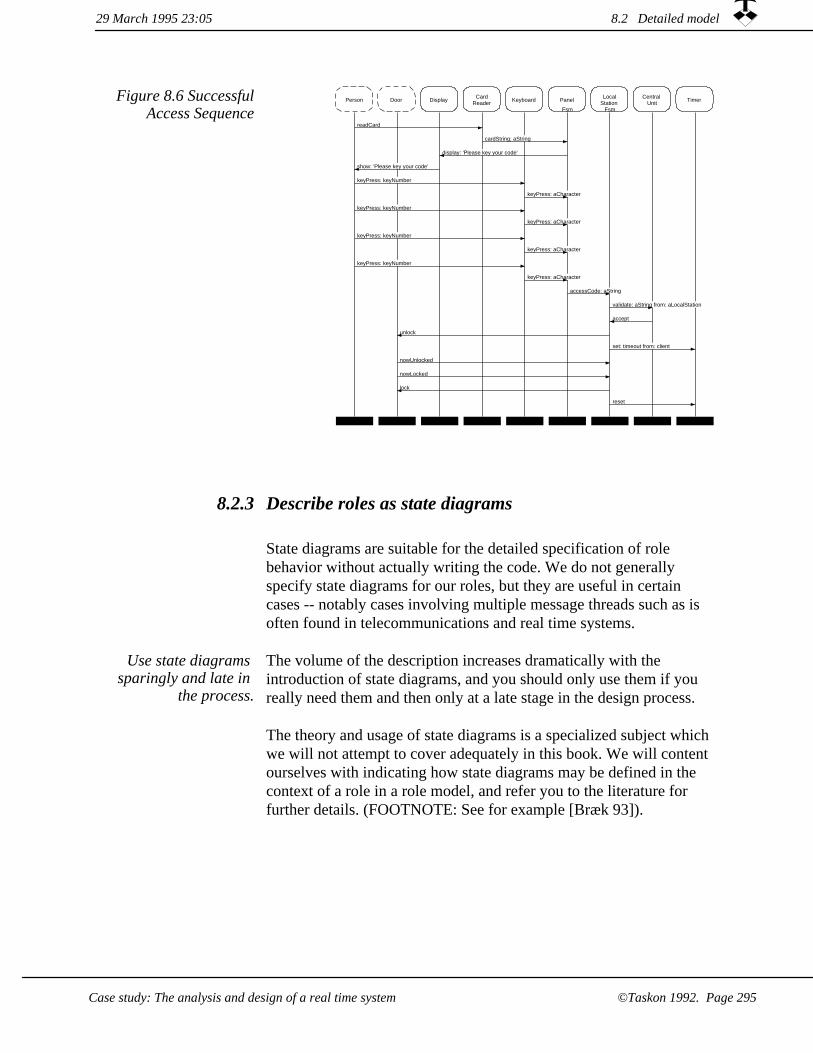
Figure 8.6 SuccessfulAccess Sequence
Person Door Display CardReader Keyboard Panel
Fsm
LocalStation
Fsm
CentralUnit Timer
readCard
cardString: aString
display: 'Please key your code'
show: 'Please key your code'
keyPress: keyNumber
keyPress: aCharacter
keyPress: keyNumber
keyPress: aCharacter
keyPress: keyNumber
keyPress: aCharacter
keyPress: keyNumber
keyPress: aCharacter
accessCode: aString
validate: aString from: aLocalStation
accept
unlock
set: timeout from: client
nowUnlocked
nowLocked
lock
reset
8.2.3 Describe roles as state diagrams
State diagrams are suitable for the detailed specification of role behavior without actually writing the code. We do not generally specify state diagrams for our roles, but they are useful in certain cases -- notably cases involving multiple message threads such as is often found in telecommunications and real time systems.
The volume of the description increases dramatically with the introduction of state diagrams, and you should only use them if you really need them and then only at a late stage in the design process.
Use state diagrams sparingly and late in
the process.
The theory and usage of state diagrams is a specialized subject which we will not attempt to cover adequately in this book. We will content ourselves with indicating how state diagrams may be defined in the context of a role in a role model, and refer you to the literature for further details. (FOOTNOTE: See for example [Bræk 93]).
8.2 Detailed model29 March 1995 23:05
Case study: The analysis and design of a real time system ©Taskon 1992. Page 295
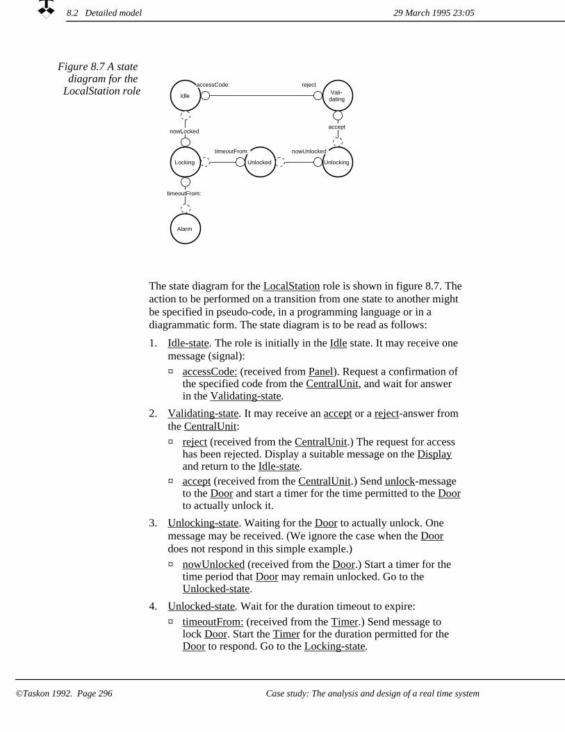
Figure 8.7 A state diagram for the
LocalStation role Idle Vali-dating
UnlockingUnlockedLocking
Alarm
acceptnowLocked
accessCode:
nowUnlockedtimeoutFrom:
timeoutFrom:
reject
The state diagram for the LocalStation role is shown in figure 8.7. Theaction to be performed on a transition from one state to another might be specified in pseudo-code, in a programming language or in a diagrammatic form. The state diagram is to be read as follows:
1. Idle-state. The role is initially in the Idle state. It may receive one message (signal):
accessCode: (received from Panel). Request a confirmation of the specified code from the CentralUnit, and wait for answer in the Validating-state.
¤
Validating-state. It may receive an accept or a reject-answer from the CentralUnit:
2.
reject (received from the CentralUnit.) The request for access has been rejected. Display a suitable message on the Display and return to the Idle-state.
¤
accept (received from the CentralUnit.) Send unlock-message to the Door and start a timer for the time permitted to the Doorto actually unlock it.
¤
3. Unlocking-state. Waiting for the Door to actually unlock. One message may be received. (We ignore the case when the Door does not respond in this simple example.)
nowUnlocked (received from the Door.) Start a timer for the time period that Door may remain unlocked. Go to the Unlocked-state.
¤
Unlocked-state. Wait for the duration timeout to expire:4.
¤ timeoutFrom: (received from the Timer.) Send message to lock Door. Start the Timer for the duration permitted for the Door to respond. Go to the Locking-state.
29 March 1995 23:058.2 Detailed model
©Taskon 1992. Page 296 Case study: The analysis and design of a real time system

Locking-state. Waiting for Door to respond to the lock command.There are two possible messages that may be received:
5.
¤ nowLocked (from Door.) Everything is OK, go to the Idle-state.timeoutFrom: (from the Timer.) The locking has been unsuccessful, possibly because the Person has prevented the door from closing and latching. Go to the Alarm-state.
¤
6. Alarm-state. Raise an alarm. The actions to be taken in the case ofan alarm are not specified in this simplified example.
The state diagrams for the other roles follow the same principles.
State diagrams and method specifications are usually alternative specifications of role behavior. The best choice depends on the particular application, and also on the implementation and run-time environments. Roles with state diagrams translate most easily to an implementation environment that also uses object state as a basic concept. In chapter 8.3.3, we will show an example of such a state-oriented language.
When implementing directly in an object-oriented language such as C++ or Smalltalk, we are concerned about implementing the methods for the different messages that the objects are to receive.
State Diagrams define an action to be triggered for each message (event) permissible in each state. A method may have to branch on object state to select the appropriate action for execution as shown in the method specification view of figure 8.8.. The figure shows a method specification view for the accessCode message sent from Panel to LocalStation. We used the states given by the state diagram in figure 8.7 to specify the method.
Method must branch on object state in
State Diagrams
if state = #Idle then [request validate state := #Validating set timeoutTimer]else
[illegalState error]
accessCode: aString
accessCode: aString
LocalStation TimerCentralUnit
set: aTimeout from: aLocalStation
Panel
Figure 8.8 Method Specification view
for LocalStation>>acces
sCode:
29 March 1995 23:05 8.2 Detailed model
©Taskon 1992. Page 297Case study: The analysis and design of a real time system

The message-passing is basically asynchronous. The different objects may therefore execute in parallel. The final decision on parallelism must be catered for in the implementation in accordance with the run-time environment.
8.2.4 Determine interfaces
The interfaces in figure 8.9 are elaborations of the messages specified in the other views given in the previous sections. This textual view is written in the OOram language which is defined in Appendix A. The language permits the specification of parameters and their types. We here show a reduced form which is particularly useful in the early stages of the modeling process and for overviews.
29 March 1995 23:058.2 Detailed model
©Taskon 1992. Page 298 Case study: The analysis and design of a real time system

Figure 8.9 Interfacesof the DetailedModel
interface 'CardReader<Person' message 'readCard' explanation "Read my identity card."
interface 'Panel<CardReader' message 'cardString:' explanation "Accept the given String from the person's
identity card."interface 'Display<Panel'
message 'display:' explanation "Display the given String."interface 'Person<Display'
message 'show:' explanation "Read my displayed text."interface 'Keyboard<Person'
message 'keyPress:' explanation "The user has pressed the indicated key."interface 'Panel<Keyboard'
message 'keyPress:' explanation "Accept given character from person."interface 'LocalStation<Panel'
message 'accessCode:' explanation "A person requests access and has offered the identification
specified by aString, which is a coded combination of information from the identity card and the received secret code."interface 'CentralUnit<LocalStation'
message 'validate:from:' explanation "Validate the given access code (aString) and return an accept-
message iff access granted, otherwise a reject-message."interface 'LocalStation<CentralUnit'
message 'accept' message 'reject'
interface 'Door<LocalStation' message 'lock' explanation "Lock the door."message 'unlock' explanation "Unlock the door."
interface 'Panel<LocalStation' message 'display:' explanation "Display the given String to the user."
interface 'Timer<LocalStation' message 'set:from:'
explanation "Set the timer to the given timeout time, send timeout message at end of time period."
message 'reset' explanation "Reset timer so that no timeout message will be sent."interface 'LocalStation<Door'
message 'nowLocked' explanation "The door has just been locked."message 'nowUnlocked' explanation "The door has just been unlocked."
interface 'LocalStation<Timer' message 'timeoutFrom:' explanation "The sending timer has reached timeout."
29 March 1995 23:05 8.2 Detailed model
©Taskon 1992. Page 299Case study: The analysis and design of a real time system

Implementation examples8.3
In a nutshellA role model is basically independent of its implementation language. We will here indicate five alternatives: implementation in C++ and Smalltalk; implementation in a distributed environment according to the standards laid down by the Object Management Group and Microsoft; and an implementation in the form of an executable specification.
We first create an object specification for the AccessControl system. It is very similar to the collaboration view of figure 8.5, but the roles are now shown with heavy outlines to indicate that they have been promoted to object specifications.
Access control example
Figure 8.10 Access Control System,
Object Specification view
car
key
dis
per
tim
loc
pan
cen
loc
doo
loc
pan
loc pan
Display
Person CardReader Panel Local
Station
CentralUnit
Keyboard
TimerDoor
This object specification focuses on the local parts of the system. The CentralUnit is shown as an environment object, which means that we do not specify all the characteristics of this unit. (It will for example, have additional functionality for setting and removing people's accessrights and for handling alarms.) The other environment roles are the Person and Door roles, since they are outside the computer system.
The following sections illustrate the transition from the object specification to implementation in different environments:
1. Object-oriented programming languages such as C++ and Smalltalk.
2. A state-oriented language such as the System Description Language (SDL)(FOOTNOTE: SDL is standardized, see [CCITT Z100]) that is commonly used in the telecommunications industry.
29 March 1995 23:058.3 Implementation examples
©Taskon 1992. Page 300 Case study: The analysis and design of a real time system

3. Distributed object systems based on standards created by the Object Management Group and Microsoft.
OOram executable specifications.4.
We will use LocalStation in the object specification shown in figure 8.10 to illustrate these alternatives.
8.3.1 Bridge to C++
Deriving a C++ class definition from
an OOram Object specification
It is straightforward to derive a C++ class definition from an OOram object specification and it can be done automatically. Corresponding concepts are shown in table 4.1 on page 165??.
The default class definition defines a class for LocalStation and an instance variable for each of its ports. The types of these variables are the names of the classes implementing the collaborators, e.g., Panel1, Door1, Timer1 and CentralUnit1.
A C++ class definition corresponding to LocalStation given in figure 8.10 could be as follows:
C++ example
enum State { Unlocked, Locking, Alarm, LockTime, Idle, Validating, MaxValidationTime};class LocalStation1;class String;class CentralUnit {public: void validatefrom(const String&, LocalStation1*); void openDoorAlarm(LocalStation1*);};class Door {public: void Lock();};class Timer {public: void setfrom(State, LocalStation1*);};class Panel;class Dictionary;class LocalStation1 {public: LocalStation1(); ~LocalStation();
8.3 Implementation examples29 March 1995 23:05
©Taskon 1992. Page 301Case study: The analysis and design of a real time system

State timeoutDictAt(State); void accept(); void accessCode(const String&); void nowLocked(); void nowUnlocked(); void reject(); void timeoutFrom(Timer*); void dpsCaution(State, const String&); void reset();private:
CentralUnit* cen; Door* doo; Panel* pan; Timer* tim;
static Dictionary* timeoutDict; State state;
};
The member functions can be produced automatically. The body can either be taken from a Method Specification view such as figure 8.8, or it can be programmed manually. Two of the member functions for the LocalStation1 class could be as follows:
void LocalStation1::accessCode(const String& code){ if(state == Idle) { state = Validating; cen->validatefrom(code, this); tim->setfrom(MaxValidationTime, this);
} else { state = Validating; dpsCaution(state, " is illegal state"); reset();
}}
void LocalStation1::timeoutFrom(Timer* timer){ switch(state) { case UnLocked: tim->setfrom(timeoutDictAt(LockTime), this); doo->Lock(); state = Locking; break;
case Locking: cen->openDoorAlarm(this); state = Alarm; break;
default: dpsCaution(state, " is illegal state."); reset(); break;
}}
How the C++ implementation and run-time environment will deal with asynchronous behavior is not covered in this brief presentation.
8.3 Implementation examples 29 March 1995 23:05
Case study: The analysis and design of a real time system©Taskon 1992. Page 302

Bridge to Smalltalk8.3.2
Deriving a Smalltalk class definition from
an OOram Object specification
It is straightforward to derive a Smalltalk class definition from an OOram object specification and it can be done automatically. Corresponding concepts are shown in table 4.1 on page 165??.
Smalltalk example A Smalltalk class definition corresponding to LocalStation is as follows:
Object subclass: #LocalStation1instanceVariableNames: 'cen doo pan tim 'classVariableNames: ''poolDictionaries: ''category: 'AccessControl'
The methods of the class can be produced automatically just as for C++. The body can also here either be taken from a Method Specification view such as figure 8.8, or it can be programmed manually. Two of the methods for the LocalStation1 class could be as follows:
LocalStation1 (LocalStation<Panel)accessCode: aString
" A person requests access and has offered the identification specified "" by aString, which is a coded combination of information from the identity "" card and the received secret code. "state == #Idle ifTrue:
[state := #Validating.cen validate: aString from: self.tim set: MaxValidationTime from: self]
ifFalse: [self dpsCaution: 'Illegal state: ' , state. self reset].
LocalStation1 (LocalStation<Timer)timeoutFrom: timer
" The sending timer has reached timeout. "state
case: #Unlocked do: [tim set: (LocalStation1 timeoutDictAt: #LockTime) * 2 from: self.doo lock.state := #Locking]
case: #Locking do:[cen openDoorAlarmFrom: self.state := #Alarm]
otherCaseDo:[self warning: state , ' is illegal state'.self reset]
How the Smalltalk environment will deal with asynchronous behavioris not covered in this brief presentation.
8.3 Implementation examples29 March 1995 23:05
Case study: The analysis and design of a real time system ©Taskon 1992. Page 303

8.3.3 Bridge to SDL
OOram may be extended to cater for special requirements
The OOram method is adaptable to different design and programming styles. Some clients in the telecommunications industry use the OOram method for early system analysis and top level design, and create their detailed designs and implementations in the standardized System Description Language (SDL) (FOOTNOTE: See [CCITT Z100] and [Bræk 93]). The clients use a version of the OOram methodand tools that have been specialized with an SDL-like view on actionsto simplify the transition from OOram role models to detailed design and implementation in SDL. An example of such an action specification is shown in figure 8.11. The action is to be performed onthe transition from the Idle state to the Validating state in figure 8.7
Figure 8.11 OOram/SDL diagram for
LocalStation >> accessCode
Idle
accessCode:
validate:from: TO CentralUnit
Validating
Trigger message(or signal)
Prestate
Poststate
Output message
Same message may trigger different
actions
The actions associated with the message timeoutFrom: received from the timer is particularly interesting, because the action to be performed depends on the current state of the object as shown in figure 8.7. This is illustrated in figure 8.12.
29 March 1995 23:058.3 Implementation examples
©Taskon 1992. Page 304 Case study: The analysis and design of a real time system

Validating
timeoutFrom:
Idle
Unlocking
timeoutFrom:
unlockAlarmFrom: TO
CentralUnit
Idle
Unlocked
timeoutFrom:
lock TO Door
set:from: TO Timer
Locking
Locking
timeoutFrom:
openAlarmFrom: TO CentralUnit
Alarm
Figure 8.12 OOram/SDL diagrams for
different actions in LocalStation
>>timeoutFrom
The SDL-language has both a graphical and textual representation. The textual representation is called SDL/PR (SDL/Phrase Representation). The SDL/PR can be produced automatically from theOOram model. Objects in the object specification maps naturally to SDL-processes. An SDL/PR definition of the LocalStation process is as follows. The System and Block description levels in SDL have been omitted here for simplification. We have likewise omitted the variable declarations.
process LocalStation;start;
nextstate Idle;
state Idle;input accessCode(aCode);
output validatefrom(aCode,thisLocalStation)/* to CentralUnit*/;nextstate Validating;
state Validating;input reject;nextstate Idle;
input timeoutFrom(aTimer);nextstate Idle;
input accept;output unlock/* to Door*/;output setfrom(unLockTime,thisLocalStation)/* to Timer*/;
nextstate Unlocking;
state Unlocking;input nowUnlocked;nextstate Unlocked;
input timeoutFrom(aTimer);output unlockAlarmFrom(thisLocalStation)/* to CentralUnit*/;
nextstate Idle;
state Unlocked;input timeoutFrom(aTimer);
29 March 1995 23:05 8.3 Implementation examples
Case study: The analysis and design of a real time system ©Taskon 1992. Page 305

output lock/* to Door*/;output setfrom(lockTime,thisLocalStation)/* to Timer*/;
nextstate Locking;
state Locking;input nowLocked;nextstate Idle;
input timeoutFrom(aTimer);output openAlarmFrom(thisLocalStation)/* to CentralUnit*/;
nextstate Alarm;
state Alarm;input nowLocked;
output doorLockedFrom(thisLocalStation)/* to CentralUnit*/;nextstate Idle;
endprocess LocalStation;
Bridge to Distributed object systems8.3.4
The separation in the why, what and how abstractions (FOOTNOTE: Figure 1.13 on page 28??) of objects makes the OOram method ideally suited for the analysis and design of distributed object systems.The method separates the object interfaces from the internal behavior. The implementation of an object can be done in different ways, and objects with the same interfaces can have different implementations.
The OMG/CORBA rom the Object Management Group and the COM/OLE from Microsoft are two approaches to realize distributed object systems. Both are based on a strict separation between the interface and implementation of objects.
We will in the following use the previously described AccessControl example in order to describe how the OOram model maps on to the Interface Description Languages of OMG/CORBA and COM/OLE. We will show how the separation of role, interface and implementation in the models matches the similar separation of interface and implementation for distributed objects.
The OOram concepts are easily mapped to the concepts of the Interface Definition Language (IDL) of OMG/CORBA and COM/OLE as shown in table 8.1.
29 March 1995 23:058.3 Implementation examples
©Taskon 1992. Page 306 Case study: The analysis and design of a real time system
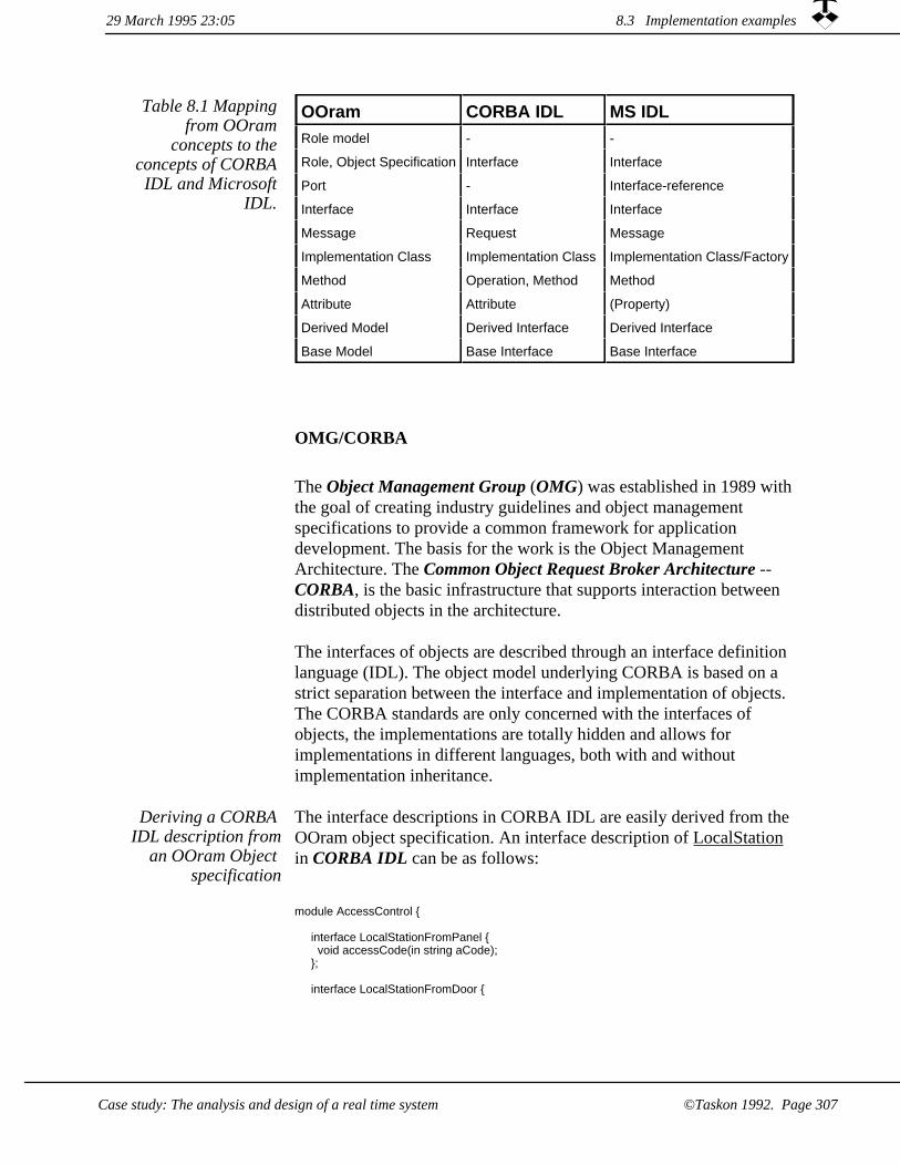
OOram CORBA IDL MS IDLRole model - -
Role, Object Specification Interface Interface
Port - Interface-reference
Interface Interface Interface
Message Request Message
Implementation Class Implementation Class Implementation Class/Factory
Method Operation, Method Method
Attribute Attribute (Property)
Derived Model Derived Interface Derived Interface
Base Model Base Interface Base Interface
Table 8.1 Mapping from OOram
concepts to the concepts of CORBA IDL and Microsoft
IDL.
OMG/CORBA
The Object Management Group (OMG) was established in 1989 withthe goal of creating industry guidelines and object management specifications to provide a common framework for application development. The basis for the work is the Object Management Architecture. The Common Object Request Broker Architecture -- CORBA, is the basic infrastructure that supports interaction between distributed objects in the architecture.
The interfaces of objects are described through an interface definition language (IDL). The object model underlying CORBA is based on a strict separation between the interface and implementation of objects. The CORBA standards are only concerned with the interfaces of objects, the implementations are totally hidden and allows for implementations in different languages, both with and without implementation inheritance.
The interface descriptions in CORBA IDL are easily derived from theOOram object specification. An interface description of LocalStation in CORBA IDL can be as follows:
Deriving a CORBA IDL description from
an OOram Object specification
module AccessControl {
interface LocalStationFromPanel { void accessCode(in string aCode);
};
interface LocalStationFromDoor {
29 March 1995 23:05 8.3 Implementation examples
Case study: The analysis and design of a real time system ©Taskon 1992. Page 307

void nowLocked(); void nowUnLocked();
};
interface LocalStationFromCentralUnit { void accept(); void reject();
};
interface LocalStationFromTimer { void timeOutFrom(in Timer aTimer);
};
interface LocalStation: LocalStationFromPanel, LocalStationFromDoor, LocalStationFromCentralUnit,
LocalStationFromTimer {
readonly attribute CentralUnit cen; readonly attribute Door doo; readonly attribute Panel pan; readonly attribute Timer tim;
};};
As there is a standard mapping from CORBA IDL to C++ and Smalltalk, it is possible to automatically derive a language-specific equivalent to an interface described in IDL.
The OOram method and CORBA both support inheritance of interfaces. OOram synthesis specifications can easily be mapped to CORBA interface descriptions.
COM/OLE
The Microsoft Component Object Model (COM) is Microsoft's foundation for distributed objects. Microsoft Object Linking and Embedding (OLE) Integration technology is built on top of COM. In COM, all applications interact with each other through collections of functions, called "interfaces". COM defines a standard way to lay out (for each of several platforms) virtual function tables in memory, and a standard way to call a function in a table. All OLE services are realized as COM interfaces.
Compared to OMG/CORBA, this is a top-down approach to distributed objects that initially provides services in a local environment with a plan to provide a distributed infrastructure in the future.
The idea behind a component-oriented architecture is that is is possible to implement the components in different programming
29 March 1995 23:058.3 Implementation examples
Case study: The analysis and design of a real time system©Taskon 1992. Page 308

languages. The binary interface standard that strictly separates interfaces from implementation makes it easy to support implementations in different programming languages.
The interface descriptions in Microsoft IIDL are easily derived from the OOram object specification. The concepts map as shown in table 8.1.
Deriving a MicrosoftIDL description from
an OOram Object specification
COM/OLE example An interface description of LocalStation in Microsoft IDL can be as follows:
interface IUnknown{ HRESULT QueryInterface();
ULONG AdRef; ULONG Release;
};
[ uuid(AF3B752C-89D0-101B-A6E4-00DD0111A658), version(1.0) ] interface ILocalSPanel: IUnknown { void accessCode([in] string aCode);
};
[ uuid(AF3B7521-89D0-101B-A6E4-00DD0111A658), version(1.0) ] interface ILocalSDoor: IUnknown { void nowLocked(); void nowUnLocked();
};
[ uuid(AF3B7522-89D0-101B-A6E4-00DD0111A658), version(1.0) ] interface ILocalSCentralU: IUnknown{ void accept(); void reject();
};
[ uuid(AF3B7523-89D0-101B-A6E4-00DD0111A658), version(1.0) ] interface ILocalSTimer:IUnknown { void timeOutFrom([in] Timer *aTimer);
};
[ uuid(AF3B7524-89D0-101B-A6E4-00DD0111A658), version(1.0) ]
interface LocalStation: { CentralUnit *get_cen();
Door *get_door(); Panel *get_pan(); Timer *get_ tim(); };
A common feature between OOram models and Microsoft COM specifications is the support of several interfaces for one object, i.e., a communication port can have several interfaces.
8.3 Implementation examples29 March 1995 23:05
©Taskon 1992. Page 309Case study: The analysis and design of a real time system

OOram executable specifications8.3.5
We have earlier stressed the importance of early prototypes and exploratory programming. Like the Norwegian farmer Peter Amb saidin an entirely different context: We may have our heads in the clouds, but keep our feet firmly planted on the ground.
Executable specifications make the abstract OOram descriptions real.They have the attractive properties of puncturing fancy abstract constructs and exposing the real problems.
Executable specifications make
the models real
Executable specifications are useful for checking program designs andany other kind of model at an early stage. In forward engineering, westart from a model and create an executable specification in order to study it in more detail. In reverse engineering, we start from an exploratory or real program that specifies some desired functionality, and create a model in order to find and define appropriate high level architecture and concepts.
OOram executable specifications are written in an object-oriented programming language, and the detailed techniques to be used for forward and reverse engineering depend on the chosen language. In principle, we have three ways of satisfying ourselves that program logic expressed in a programming language conforms to a given design expressed in a role model:
Checking correspondence
between program and model
The program code could be analyzed by a suitable algorithm and compared with the role model information. This is a hard researchproblem and probably not feasible in the general case.
1.
We could implement the specifications in a new, high level language which was designed so that the code could be mapped on to the OOram concepts. This is an interesting alternative whichwe are currently exploring.
2.
We could monitor the execution of typical and dangerous cases, and record all message interaction with current object state and message details. The recording can be compared to the relevant role models automatically, and illegal messages can be flagged.
3.
29 March 1995 23:058.3 Implementation examples
©Taskon 1992. Page 310 Case study: The analysis and design of a real time system

We have chosen the last solution because it provides the designer withimportant insights into the operation of his design and because it is applicable in all cases.
This variant of executable specifications is called monitored execution. A monitored execution collects a trace of all messages being passed between the observed objects.
Facilities for monitored execution can take many forms. The Taskon experimental facility automatically produces three reports: An Object Collaboration report, an Execution Scenario report, and a Textual Trace report.
Monitored execution gives important
insights
We have created an executable specification for part of the AccessControl example, and have run a number of monitored executions under different conditions. The object specification view for the example is shown in figure 8.13, and the results of an execution are described in the following pages. We show all the collected information in our example, but would want to show a filtered subset in more complex situations.
Figure 8.13 Object specification view for
simplified AccessControl
system with dummy Panel, Door and
CentralUnit
tim
loc
loc pan
doo
loc
cen locPanel LocalStation
CentralUnit
Timer
Door
The environment roles CentralUnit, Panel and Door are marked as object specifications, because we implement them as dummy classes for testing purposes.
The Object Collaboration report
shows all observed objects and their interaction paths
The Object Collaboration report shown in figure 8.14 is similar to a collaboration view, but we use rectangles rather than super-ellipses to emphasize that we show an object structure rather than a role structure. There is one rectangle for each observed object; one port symbol for the start of each observed interaction path; and associated with each port are the messages actually observed as sent through thatport. We only show the messages observed from port 15; there are similar message lists associated with all the other ports.
8.3 Implementation examples29 March 1995 23:05
©Taskon 1992. Page 311Case study: The analysis and design of a real time system
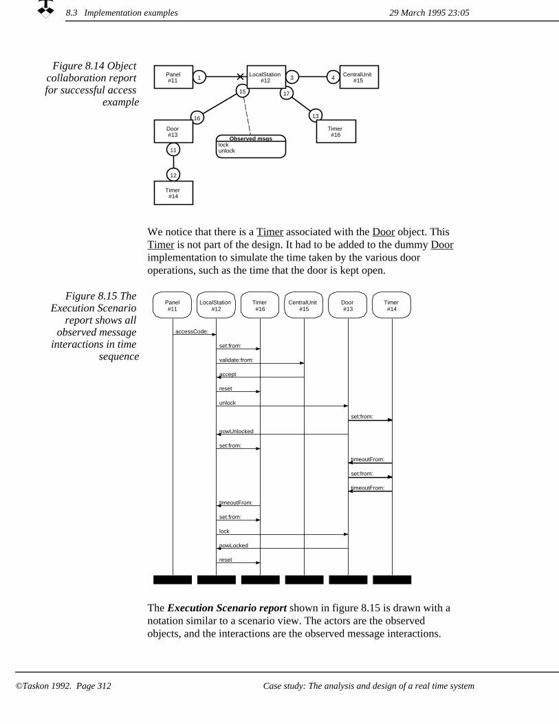
Figure 8.14 Object collaboration report for successful access
example
3 4
17
13
1
11
12
15
16
Panel#11
Observed msgslockunlock
LocalStation#12
Timer#16
CentralUnit#15
Door#13
Timer#14
We notice that there is a Timer associated with the Door object. This Timer is not part of the design. It had to be added to the dummy Door implementation to simulate the time taken by the various door operations, such as the time that the door is kept open.
Figure 8.15 The Execution Scenario
report shows all observed message
interactions in time sequence
Panel#11
LocalStation#12
Timer#16
CentralUnit#15
Door#13
Timer#14
accessCode:
set:from:
validate:from:
accept
reset
unlock
set:from:
nowUnlocked
set:from:
timeoutFrom:
set:from:
timeoutFrom:
timeoutFrom:
set:from:
lock
nowLocked
reset
The Execution Scenario report shown in figure 8.15 is drawn with a notation similar to a scenario view. The actors are the observed objects, and the interactions are the observed message interactions.
29 March 1995 23:058.3 Implementation examples
Case study: The analysis and design of a real time system©Taskon 1992. Page 312

Light arrows in the Execution Scenario report indicate messages that conform to the role models; heavy arrows indicate non-conformance. As expected, all interaction with the simulation Timer added to the Door for simulation purposes is marked as non-conforming.
Figure 8.16 The Textual Trace report
gives complete description of all
interactions
01 OK test 02 TASKON/OOram Monitored Execution, 12 April 1994 at 3:45:24 pm 03 program version e15-t10 04 05 Panel#11 >> accessCode: ('personIdentAndCode') >> LocalStation#12 06 LocalStation#12 >> set:from: (1 {LocalStation#12}) >> Timer#16 07 LocalStation#12 >> validate:from: ('personIdentAndCode' {LocalStation#12})
>> CentralUnit#15 08 CentralUnit#15 >> accept () >> LocalStation#12 09 LocalStation#12 >> reset () >> Timer#16 10 LocalStation#12 >> unlock () >> Door#13 11 TRACE-Door#13: Lock released at 3:45:31 pm 12 )-- Door#13 >> set:from: (2 {Door#13}) >> Timer#14 13 Door#13 >> nowUnlocked () >> LocalStation#12 14 LocalStation#12 >> set:from: (5 {LocalStation#12}) >> Timer#16 15 )-- Timer#14 >> timeoutFrom: ({Timer#14}) >> Door#13 16 TRACE-Door#13: Door opened at 3:45:33 pm 17 )-- Door#13 >> set:from: (2 {Door#13}) >> Timer#14 18 )-- Timer#14 >> timeoutFrom: ({Timer#14}) >> Door#13 19 TRACE-Door#13: Door closed at 3:45:35 pm 20 Timer#16 >> timeoutFrom: ({Timer#16}) >> LocalStation#12 21 LocalStation#12 >> set:from: (2 {LocalStation#12}) >> Timer#16 22 LocalStation#12 >> lock () >> Door#13 23 TRACE-Door#13: Lock activated at 3:45:37 pm 24 Door#13 >> nowLocked () >> LocalStation#12 25 LocalStation#12 >> reset () >> Timer#16
The Textual Trace report shown in figure 8.16 displays all information that has been collected, but it makes hard and boring reading. It is, however, useful for studying details in the execution such as parameter and return values.
The trace is interpreted as follows:
shows the name of the test.Line 01
Line 02 identifies time and date of the execution.
identifies the version of the program being executed.Line 03
Line 05 shows a message send.The syntax of a message report is as follows:
'sender object' >> 'message name' ( 'message parameters' ) >> 'receiver object'For example, line 5 is to be read
The object Panel#11 sendsthe message named accessCode:with a String parameter: 'personIdentAndCode'to the object LocalStation#12
Line 11 shows a program trace. The programmer may insert informative messages in his code. These messages are preceded by 'TRACE' in the report.
29 March 1995 23:05 8.3 Implementation examples
Case study: The analysis and design of a real time system ©Taskon 1992. Page 313

shows illegal message send. Message sends are checked against the port interfaces specified in the role models. If a message is not in accordance with the role model, the report line begins with the symbol')--'. The messages in lines 12, 15, 17 and 18 are examples of nonconformance. They are all caused by a Timer used in the dummy Door implementation to make it appear to open and close at determined times.
Line 12
Run-time errors are reported with a line beginning with 'CAUTION'; the execution continues if at all possible.
Not shown
Not shown Message return values (Smalltalk messages always return a value) are given on the following line if different from the receiver object. The return value is preceded by the keyword RETURN:
RETURN return value
8.3 Implementation examples 29 March 1995 23:05
Case study: The analysis and design of a real time system©Taskon 1992. Page 314

Chapter 9Case study: The creation of a framework
This case is about low-level programming. We create a reusable framework written in Smalltalk, but the principles presented should be equally applicable to other programming languages.
First step: Identify consumers and consumer needs (p. 314)Second step: Perform a cost-benefit analysis (p. 317)Third step: Perform reverse engineering of existing programs (p. 319)
Container-Component HierarchyModel-View-ControllerMouse and Keyboard InputThe Scroller role model
Fourth step: Specify the new framework (p. 343)Fifth step: Document the framework as patterns describing how to solve problems (p. 345)
Pattern 1: The ToolPattern 2: Fixed Proportion Tool LayoutPattern 3: Flexible Tool LayoutPattern 4: The ControllerPattern 5: The Model ObjectPattern 6: The View
Sixth step: Describe the framework's design and implementation (p. 354)Seventh step: Inform the consumer community (p. 362)
29 March 1995 23:05
Case study: The creation of a framework ©Taskon 1992. Page 315

This case study illustrates the creation of frameworks. We illustrate how a complex construct can be hidden in a framework so that the application programmer can apply it safely and simply while retainingthe power to create arbitrarily sophisticated solutions.
The case we have chosen is the work we have done to adapt the visualparts hierarchy of Objectworks release 4.0 to our requirements. This seems to be work which never ends: We keep finding better concepts and solutions that reduce the burden on the application programmer and increase product quality. We have flattened several years of iterative development into a single step in the case study, and have even included an improved scheme for the changed-update construct that we were exploring while this chapter was written.
Guide to the case study
We presented a general process for creating frameworks in chapter 5.3on page 212??. The process is reflected in this case study report, you will find the following subsections:
1. Identify consumers and consumer needs.
2. Perform a cost-benefit analysis.
Perform reverse engineering of existing programs.3.
4. Specify the new framework.
Document the framework as patterns describing how to solve problems.
5.
Describe the framework's design and implementation.6.
Inform the consumer community.7.
We have attempted to keep the presentation within reasonable bounds,and have omitted many design and implementation details. We hope that what remains is still sufficiently substantial to convince you of the need for information hiding and the ability of our technology to satisfy this need.
29 March 1995 23:05
©Taskon 1992. Page 316 Case study: The creation of a framework

9.1 First step: Identify consumers and consumer needs
In a nutshellIn this case, the consumers were ourselves and our needs were dictated by market pull for full color and integration with the platform's windowing system
The consumers are ourselves
The consumers of this framework case study are the system developers at Taskon. At the time when we first heard of Objectworks\Smalltalk release 4.0, we had developed a large system product consisting of some 1,500 classes, 37,000 methods, and some 300,000 lines of Smalltalk code running under Objectworks\Smalltalkrelease 2.5. The code was very compact with extensive reuse, and a typical runtime image might consist of more than a quarter million objects.
An important part of the product was its sophisticated editors. Our editors were based on the Model-View-Controller (MVC) framework found in earlier releases of the Objectworks\Smalltalk library, but with substantial extensions to satisfy the needs of our editors.
Objectworks\Smalltalk release 4.0 provided a number of improvements that were sorely needed by our customers, and we decided to adapt it as quickly as possible.
Release 4.0 represented major
improvements
From our standpoint, the most dramatic changes were the entirely newclass hierarchy for managing windows and their parts. The big question was how the modified class library would influence our system. To answer this question, we established a project to create an OOram framework which modified and extended the visual parts of release 4.0 to make it satisfactory for our purposes.
Our main requirement was that we wanted to create sophisticated userinterfaces quickly, simply and safely. This implies that we wanted to push as much of the problem complexity as possible into the framework, that we wanted a small surface area between the framework and the application, and that we wanted the programmer toretain full control over the model functionality and the layout of the editors in the window.
Simple, yet powerful user interface
development
Specifically:
We wanted all the new capabilities of the new release.1.
We wanted to retain the functionality of our existing editors, because we liked them and so did our customers.
2.
9.1 First step: Identify consumers and consumer needs29 March 1995 23:05
©Taskon 1992. Page 317Case study: The creation of a framework

3. We wanted to reduce the burden on the application programmer by significantly reducing the surface area between the framework and its derivatives.
4. We wanted to define the surface area between the framework and its derivatives so that the framework could be improved without threatening the derivatives.
We wanted to consider the automatic enforcement or checking of framework constraints to improve the quality of the derivatives.
5.
29 March 1995 23:059.1 First step: Identify consumers and consumer needs
Case study: The creation of a framework©Taskon 1992. Page 318

9.2 Second step: Perform a cost-benefit analysis
In a nutshellWe wanted to combine the added functionality with a reduced number of editor glitches.
Benefit: Our customers wanted it
When we first got access to Objectworks release 4.0, the decision to adopt it was trivial: our customers wanted its color capabilities and itscloser integration with the platform windowing system, and they wanted it NOW. So we had no choice but to convert our programs to the new release as quickly as possible and cost was really not an issue.
Benefit: Our programmers wanted
it
In addition, our application programmers appreciated that the new architecture made their task easier, and wanted us to adapt to the new release because they believed it would make them more effective (removing some of the hassle, but none of the fun.)
The phenomenon covered by the visual part hierarchy is of central importance to our business because it permeates all our task-oriented tool products. Certain aspects of the changed-update construct had continued to cause difficulties even after several stages of improvements. (The solution presented here includes an even later revision, which our application programmers hope will finally prove to be the ultimate solution.)
Benefit: We needed to improve our MVC
framework
We estimated that reverse engineering of release 4.0, forward engineering, design and implementation of a new framework would take 8 person-months. Retrofitting the new framework in existing program products to make them compatible with release 4.0 would take another 12 person-months.
Cost: Designing a new framework
BOX: Resource estimation is very hard with extensive reuseI frankly find it extremely hard to estimate such programming projects. It is much like estimating the time needed to solve a crossword puzzle. I have an idea about where I am, where I want to be and the things that need to be done to get there. Most problems are benign and are solved with the estimated effort. Some problems just disappear on closer scrutiny, but this is more than offset by the few problems which prove to be really hard.
It seems to me that there are only three ways of making firm project commitments: either keep the goal fixed with time and resources flexible, or keep time and resources fixed with the detailed specifications of the goal flexible, or make the bureaucracy surrounding the project so large that it completely dominates the unknown, creative part.
9.2 Second step: Perform a cost-benefit analysis29 March 1995 23:05
©Taskon 1992. Page 319Case study: The creation of a framework

In our case, the work was harder than expected and the available time and resources were fixed due to commitments to customers. We have,therefore, been forced to go through several iterations, even if we in this presentation pretend there has been only one.
29 March 1995 23:059.2 Second step: Perform a cost-benefit analysis
©Taskon 1992. Page 320 Case study: The creation of a framework

Third step: Perform reverse engineering of existing programs
9.3
In a nutshellReverse engineering of existing programs was very enlightening and helped us identify a number of powerful object patterns.
Third step: Reverse engineering
The third step was to do a reverse engineering analysis of the new visual parts hierarchy of Objectworks\Smalltalk release 4.0. The results are summarized below.
We also did reverse engineering on all our editors and determined how they could be reimplemented under the new framework. We found that while the new solution was a great step forward, there werestill some glitches which made it necessary for us to create our own solution.
The goal of the reverse engineering step was to understand how release 4.0 managed windows with all their different subareas. We first browsed through the class library, and found that classes and methods were consistently and well commented. We studied the class hierarchy: figure 9.1 shows the inheritance relationships between the classes we have found to be most relevant to our study. We must admit that the hierarchy did not help us understand the design of a window and its parts. We clearly needed to study how the objects collaborate in an actual window, and not how their classes are related in the class hierarchy.
The class hierarchy was not helpful
9.3 Third step: Perform reverse engineering of existing programs29 March 1995 23:05
Case study: The creation of a framework ©Taskon 1992. Page 321

Object- Controller- - ControllerWithMenu- - - ParagraphEditor- - ScrollbarController- - StandardSystemController- - WidgetController- DisplaySurface- - Window- - - ScheduledWindow- InputSensor- - TranslatingSensor- - WindowSensor- InputState- Model- - PopUpMenu- - ScrollValueHolder- - ValueModel- - - PluggableAdaptor- - - ValueHolder- - - - TextCollector- Screen- SharedQueue- VisualComponent- - VisualPart- - - CompositePart- - - - BorderDecorator- - - DependentPart- - - - View- - - - - AutoScrollingView- - - - - - ComposedTextView- - - - - - - TextCollectorView- - - - - BooleanWidgetView- - - - - - ActionButton- - - - - - LabeledBooleanView- - - - - Scrollbar- - - Wrapper- - - - TranslatingWrapper- - - - - LayoutWrapper- - - - - - BoundedWrapper- - - - - - - BorderedWrapper- - - - - ScrollWrapper
Figure 9.1 A part of the Smalltalk class
hierarchy
Classes of interest to our study are shown in bold typeface.
Dissecting a Transcript window
In the best Smalltalk tradition, we next tried to understand the new design by analyzing a concrete example. We first tried to investigate aprogram Browser, but found it far too complex for our purpose. So weselected the System Transcript, which is the simplest window of all. The System Transcript is a text editor where programs can write messages to the user, and where the user can type simple commands. Its appearance on the screen is shown in figure 9.2.
Menu barScroll UP button
Scrollbar
Scroll DOWN button
Text editor
DecWindows buttonsFigure 9.2 A System Transcript
29 March 1995 23:059.3 Third step: Perform reverse engineering of existing programs
Case study: The creation of a framework©Taskon 1992. Page 322

The title bar at the top with its resizing and other buttons is managed by the platform windowing system (DecWindows in this case) and is not represented as Smalltalk objects. Our interest focuses on the contents of the window: the menu bar, the scrollers and the text editor itself.
We activated the System Transcript window, typed a program interrupt command, and inspected its object structure. We found a large number of interconnected objects, and extracted the ones that our experience indicated were of interest to our study. The result is shown in figure 9.3.
9.3 Third step: Perform reverse engineering of existing programs29 March 1995 23:05
Case study: The creation of a framework ©Taskon 1992. Page 323

Figure 9.3 The main objects controlling the behavior of the Transcript window
ws
cps
ct
ds
m
ss
wsws ws
ds
m
s
cps
ct
cps
ct
cp
s
wsw
sw m
s v c
m
ds
ww
s
cp ct
ww
m
m
ds
m
cps
ct
cps
ctct
cps
ct
cp
m
cp
ct
c
v
cp
ct
m
c
v
cp
ct
cp
ct
m m
mm
cp
ct
c
v
m
v
cc
v
m
ds
581StandardSystem
Controller
3822Scheduled
Window
2259WindowSensor
2294Translating
Sensor
13540Translating
Sensor
1404Translating
Sensor
13379Translating
Sensor
610Translating
Sensor
5116Border
Decorator
11804TextCollector
9943BorderedWrapper
12188Scroll
Wrapper
9795Text
CollectorView
3003Paragraph
Editor
7050BorderedWrapper
791LabeledBoolean
View
6708Widget
Controller
6909Widget
Controller
2873PluggableAdaptor
10916BoundedWrapper
9302PluggableAdaptor
464ActionButton
12982BorderedWrapper
14782Composite
Part
10589BorderedWrapper
14455ActionButton
9302PluggableAdaptor
112Widget
Controller
8196BorderedWrapper
444Scrollbar
15219ScrollbarController
cp
ct
Objects are shown as rectangles annotated with the object identifier and the class name. Circles denote instance variables; collections are doubled. They are annotatedas follows:
c controller cp component cps componentsct container ds dependents m models sensor v view w windowws windowSensor
29 March 1995 23:059.3 Third step: Perform reverse engineering of existing programs
Case study: The creation of a framework©Taskon 1992. Page 324
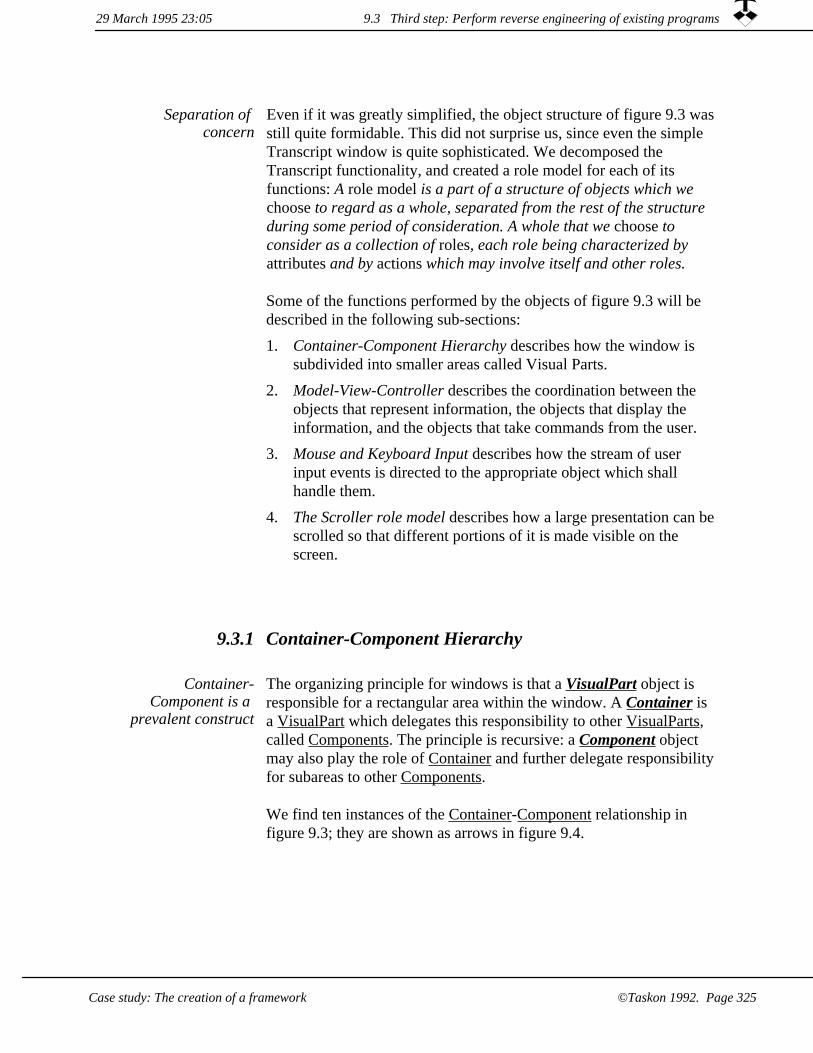
Separation of concern
Even if it was greatly simplified, the object structure of figure 9.3 wasstill quite formidable. This did not surprise us, since even the simple Transcript window is quite sophisticated. We decomposed the Transcript functionality, and created a role model for each of its functions: A role model is a part of a structure of objects which we choose to regard as a whole, separated from the rest of the structure during some period of consideration. A whole that we choose to consider as a collection of roles, each role being characterized by attributes and by actions which may involve itself and other roles.
Some of the functions performed by the objects of figure 9.3 will be described in the following sub-sections:
Container-Component Hierarchy describes how the window is subdivided into smaller areas called Visual Parts.
1.
2. Model-View-Controller describes the coordination between the objects that represent information, the objects that display the information, and the objects that take commands from the user.
Mouse and Keyboard Input describes how the stream of user input events is directed to the appropriate object which shall handle them.
3.
4. The Scroller role model describes how a large presentation can bescrolled so that different portions of it is made visible on the screen.
9.3.1 Container-Component Hierarchy
The organizing principle for windows is that a VisualPart object is responsible for a rectangular area within the window. A Container is a VisualPart which delegates this responsibility to other VisualParts, called Components. The principle is recursive: a Component object may also play the role of Container and further delegate responsibilityfor subareas to other Components.
Container-Component is a
prevalent construct
We find ten instances of the Container-Component relationship in figure 9.3; they are shown as arrows in figure 9.4.
9.3 Third step: Perform reverse engineering of existing programs29 March 1995 23:05
Case study: The creation of a framework ©Taskon 1992. Page 325

Figure 9.4 Ten instances of the
Container-Component relation
The third object from the left in the top row is the 3822-ScheduledWindow object. It is the root of the visual component hierarchy and forms the container for the BorderDecorator object.
The 5116-BorderDecorator object is the Component of the ScheduledWindow, and also the Container of three Components: the 7050-BorderedWrapper object, which is responsible for the menu bar area; the 10916-BoundedWrapper object, which is responsible for the area for the scrollbar and scroll buttons; and the 12188-ScrollWrapper, which is responsible for the text editor area. Each of these Components act as Containers and delegate their responsibilities to other Components recursively down to the leaf Components such as 9795-TextCollectorView.
Figure 9.5 Area of concern
The Container-Component construct explains the visual parts tree structure by focusing on a typical parent-child pair.
dw
up
Container
Component
A Container has the characteristics of a father object in a visual parts tree structure. A Container manages some area within a window, presents information to the user and possibly takes input pertaining to this presentation from the user. It delegates at least some of this work to one or more Components, which it positions within its own area.
A Component has the characteristics of a son object in the visual parts tree structure. A Component manages some area within a window, presents information to the user and possibly takes input pertaining to this presentation from the user.
Figure 9.6 The roles and their
responsibilities
Figure 9.7 Stimulus -Response
All messages can be a stimulus message.
9.3 Third step: Perform reverse engineering of existing programs 29 March 1995 23:05
©Taskon 1992. Page 326 Case study: The creation of a framework

The message interfaces
The most interesting parts of this role model are the message interfaces. Most relevant objects play both roles. The role model help us segregate the messages that are sent down the component hierarchyfrom the ones that are sent up. The most important messages are illustrated in figure 9.8.
Figure 9.8 Simplifiedinterfaces for the
Container-Component construct dw
up
Container Component<Containerbounds:container:displayOn:
Container<ComponentgraphicsContextFor:invalidateRectangle:forComponent:localPointToGlobal:forComponent:
Component
29 March 1995 23:05 9.3 Third step: Perform reverse engineering of existing programs
Case study: The creation of a framework ©Taskon 1992. Page 327

Figure 9.9 Textual interface view
interface 'Container<Component' explanation "We require that the Container shall accept these messages in any
sequence. This means that it is the responsibility of the Container to be prepared forany and all of these messages after it has sent the container:-message to the Part."
message 'graphicsContextFor:' explanation "Return aGraphicsContext for set up for aComponent."param 'aComponent'
message 'invalidateRectangle:forComponent:' explanation "Invalidate the Rectangle aRectangle. Propagate a damage
rectangle up the containment hierarchy. This will result in a displayOn: aGraphicsContext being sent to the receiver."
param 'aRectangle'param 'aComponent'
message 'localPointToGlobal:forComponent:' explanation "Convert aPoint in coordinate system of aPart to a point in the
window's coordinate system."param 'aPoint'param 'aPart'
interface 'Component<Container' message 'bounds:'
explanation "An actual bounding rectangle is being asserted, aRectangle is in the coordinate system of the Part. The bounds: message originates at the top of a hierarchy (usually a ScheduledWindow) and passes down to each VisualComponent. ScheduledWindows send bounds: to their single component whenopened or resized. CompositeParts uses this message to do layout of tiled components. BoundedWrapper uses the newBounds rectangle as the actual bounding rectangle. Many VisualComponents do nothing. Do not send a changedBounds: message back up the hierarchy in response to this message."
param 'aRectangle'message 'container:'
explanation "The Part is being placed in containment hierarchy inside of aContainer."
param 'aContainer'message 'displayOn:'
explanation "Display the receiver on the given GraphicsContext, which is set up for the receiver's coordinate system."
param 'aGraphicsContext'
Figure 9.10 illustrates how the design of the Transcript window can beconsidered as composed of repeated applications of this base model.
Using synthesis to recreate part of object structure
29 March 1995 23:059.3 Third step: Perform reverse engineering of existing programs
©Taskon 1992. Page 328 Case study: The creation of a framework

dw
up
dw
up
dw up
dw
up
dw
up
ScheduledWindow
BorderDecorator
BorderedWrapper
ScrollWrapper
TextCollector
View
Container
Component
Figure 9.10 Repeated
applications of the Container-
Component model in the Transcript
structure
Implementation comments
Whenever there is a change in the data, the window (or parts of it) hasto be redisplayed. There are basically two mechanisms for doing this in a component: invalidation and direct display. Invalidation is illustrated in the scenario of figure 9.11, and direct display is illustrated in the scenario of figure 9.12. Sketches of the corresponding programs are given below.
Figure 9.11 Scenarioof display through
invalidation
ScheduledWindow
BorderDecorator
BorderedWrapper
ScrollWrapper
TextCollector
View
invalidateRectangle:forCo
invalidateRectangle:forComponent:
invalidateRectangle:forComponent:
invalidateRectangle:forComponent:
displayOn:
displayOn:
displayOn:
displayOn:
Invalidate The message VisualPart>>invalidateRectangle: aRectangle causes an event in the window which is equivalent to a display event from the platform windowing system.
9.3 Third step: Perform reverse engineering of existing programs29 March 1995 23:05
©Taskon 1992. Page 329Case study: The creation of a framework

01 aTextCollectorView invalidateRectangle: aRectangle repairNow: aBoolean02 . aScrollWrapper
invalidateRectangle: rect1repairNow: aBoolean forComponent: aTextCollectorView
03 . . aBorderedWrapper invalidateRectangle: rect2
repairNow: aBoolean forComponent: aScrollWrapper
04 . . . aBorderDecorator invalidateRectangle: rect3
repairNow: aBoolean forComponent: aBorderedWrapper
05 . . . . aScheduledWindow invalidateRectangle: rect4 repairNow: aBoolean forComponent: aBorderedWrapper
If aBoolean is false, the following will take place some time in the future, if it is true, it will take place immediately. 06 . . . anEdgeWidgetWrapper displayOn: aGraphicsContext07 . . . . aTextCollectorView displayOn: aGraphicsContext
The above is the general algorithm. It gives all parts in a composite window the opportunity to display themselves within the specified Rectangle (which is transformed appropriately on its way up and down the hierarchy.) The alternative algorithm is usually simpler and faster, and is suitable when it is known which parts need to be displayed:
ScheduledWindow
BorderDecorator
BorderedWrapper
ScrollWrapper
TextCollector
View
graphicsContextFor:
graphicsContextFor:
graphicsContextFor:
graphicsContextFor:
Figure 9.12 Scenarioget
aGraphicsContext for local display
01 gc := aTextCollectorView graphicsContext02 . aScrollWrapper graphicsContextFor: aTextCollectorView03 . . aBorderedWrapper graphicsContextFor: aScrollWrapper04 . . . aBorderDecorator graphicsContextFor: aBorderedWrapper05 . . . . aScheduledWindow graphicsContextFor: anEdgeWidgetWrapper06 gc 07 paint: aTextCollectorView backgroundColor;08 displayRectangle: damageArea;09 paint: aTextCollectorView foregroundColor.10 aTextCollectorView displayOn: gc
Note that in the previous case, the ScheduledWindow cleared the area before asking for the display; in this case it is the responsibility of the TextCollectorView to clear any garbage from the affected area (lines 06 through 09) before displaying (line 10).
In lines 01 through 05, a GraphicsContext is created and provided
29 March 1995 23:059.3 Third step: Perform reverse engineering of existing programs
©Taskon 1992. Page 330 Case study: The creation of a framework

with the proper value for coordinate translation. The GraphicsContext forms the link to the underlying platform window system, which does the actual rendering on the screen. It can only work if it is created on aDisplaySurface or one of its subclasses such as ScheduledWindow.
Containers and Components share an interface containing the messages that they may receive from any object. We define VisualPart as a common role, and VisualPartClient as its general client as shown in figures 9.13 and 9.14.
Additional interface to VisualParts
Figure 9.13 A VisualPart-Client collaboration view
vp VisualPartVisualPartClient
A VisualPart manages some area within a window, presents information to the user and possibly takes input pertaining to this presentation from the user.
A VisualPart Client represents any object which knows about a Container or a Component.
Figure 9.14 VisualPart<VisualPa
rtClient graphical interface view
vp
VisualPart<VisualPartClientboundscomponentscontainerinvalidateRectangle: aRectanglelocalPointToGlobal: aPointpreferredBoundstopComponent
VisualPartVisualPartClient
29 March 1995 23:05 9.3 Third step: Perform reverse engineering of existing programs
©Taskon 1992. Page 331Case study: The creation of a framework

Figure 9.15 VisualPart<VisualPa
rtClient textual interface view
interface 'VisualPart<VisualPartClient' message 'bounds'
explanation "Answer a Rectangle that represents the Component's actual bounding rectangle on the screen in the Component's coordinate system."
message 'invalidateRectangle:' explanation "Invalidate the Rectangle aRectangle. Propagate a damage
rectangle up the containment hierarchy. This will result in a displayOn: aGraphicsContext being sent to the receiver."
param 'aRectangle'message 'localPointToGlobal:'
explanation "Convert a point in local coordinates to a point in the top windows coordinate system. Forwarded to the receiver's container."
param 'aPoint'message 'preferredBounds'
explanation "Answer a Rectangle, which is the preferred bounds of the receiver in the receiver's coordinate system."
message 'topComponent' explanation "Answer the top component in the receiver's hierarchy. If the
receiver is not in a hierarchy answer the receiver. (Taskon comment: This are very questionable semantics. The protocol of the usual topComponent (ScheduledWindow) is different from the protocol of an arbitrary Component. We have modified the specification to return aScheduledWindow or nil)."
message 'components' explanation "Answer a Collection containing the receiver's components.
Answer an empty Collection if this is a leaf node."message 'container'
explanation "Answer the receiver's container, or nil."
Notice the pair of almost identical messages in the VisualPart<VisualPartClient interface and the Container<Component interface: graphicsContext and graphicsContextFor: aComponent. We need the second form because the responsibility for providing the proper coordinate translation rests with the container. A composite container such as the BorderDecorator will provide different translation parameters for its different parts, and must know the identity of the part. Our convention is that graphicsContext returns a GraphicsContext set up for the receiver, while graphicsContextFor: is used to request a GraphicsContext for one of the receiver's components.
The composite does not tell anything new
We could easily create a composite of the Container-Component model and the Client-VisualPart model; the result of this synthesis is the derived model shown with white roles in figure 9.16. This model is substantially more complex than the two base models and does not give any new information. We will normally not create the derived model, but leave the synthesis of individual roles to the implementation stage.
29 March 1995 23:059.3 Third step: Perform reverse engineering of existing programs
©Taskon 1992. Page 332 Case study: The creation of a framework
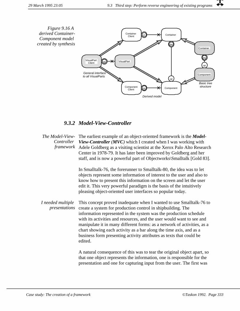
cp
ct
vp
dw
up
dw
up
VisualPartVisualPartClient
Container
Component
ContainerClient
ComponentClient
Container
Component
Derived model
Basic treestructure
General interfaceto all VisualParts
Figure 9.16 A derived Container-Component model
created by synthesis
9.3.2 Model-View-Controller
The earliest example of an object-oriented framework is the Model-View-Controller (MVC) which I created when I was working with Adele Goldberg as a visiting scientist at the Xerox Palo Alto ResearchCenter in 1978-79. It has later been improved by Goldberg and her staff, and is now a powerful part of Objectworks\Smalltalk [Gold 83].
The Model-View-Controller framework
In Smalltalk-76, the forerunner to Smalltalk-80, the idea was to let objects represent some information of interest to the user and also to know how to present this information on the screen and let the user edit it. This very powerful paradigm is the basis of the intuitively pleasing object-oriented user interfaces so popular today.
This concept proved inadequate when I wanted to use Smalltalk-76 to create a system for production control in shipbuilding. The information represented in the system was the production schedule with its activities and resources, and the user would want to see and manipulate it in many different forms: as a network of activities, as a chart showing each activity as a bar along the time axis, and as a business form presenting activity attributes as texts that could be edited.
I needed multiple presentations
A natural consequence of this was to tear the original object apart, so that one object represents the information, one is responsible for the presentation and one for capturing input from the user. The first was
29 March 1995 23:05 9.3 Third step: Perform reverse engineering of existing programs
Case study: The creation of a framework ©Taskon 1992. Page 333

called the model object, the second was called the view object and the third was called the controller object. This gave the freedom to have many different presentations and input facilities for the same object, and even to have several views of a given model on the screen simultaneously.
The object-oriented, direct manipulation user interface gives the user an illusion of working directly with the apparently concrete information objects. The Model-View-Controller breaks this illusion when the user has several views on the same information object simultaneously. This is fortunately of no concern to the professional planner who is manipulating different views of the same plan even in the manual systems.
BOX: Flexible mapping of Model-View-Controller roles to objectsThere has been many discussions in professional forums about the wisdom of this scheme. Would it be sufficient with two objects (editor and model), or should the original idea of a single object doing all three jobs be retained. With role modeling, this is not an issue. We can map roles onto objects in any way we please, and the three roles of Model, View, and Controller can be mapped onto three, two or one object according to the merits of the problem.
If required, we can retain the valuable user illusion of concrete information objects by the simple expedient of constraining the user interface so that it only shows one view of each information object at the time.
Figure 9.17 shows the five instances of the Model-View-Controller triad in the Transcript of figure 9.3. Four of them manage the menu bar, the up scroll button, the scrollbar, and the down scroll button. Thefifth one is farthest to the right where 11804-TextCollector plays the role of a Model, 3003-ParagraphEditor plays the role of Controller, and 9795-TextCollectorView plays the role of View.
Model-View-Controller (MVC)
Figure 9.17 Five instances of the
Model-View-Controller (MVC)
construct
29 March 1995 23:059.3 Third step: Perform reverse engineering of existing programs
Case study: The creation of a framework©Taskon 1992. Page 334

We will now present a role model of the Model-View-Controller as it is implemented in Objectworks\Smalltalk release 4.0. We concentrate on the general mechanism, ignoring the specializations for the Transcript text manipulation.
Figure 9.18 Area of concern
The Model-View-Controller (MVC) paradigm is fundamental to all Objectworks\Smalltalk thinking about dividing responsibility between objects. The basic idea is that we want a clear separation between the representation of knowledge, called the Model, and the means provided for a user to inspect and manipulate this information in the View and Controller respectively.
outin ComputerSystemUser
Figure 9.19 Environment model
Figure 9.20 Stimulus-Response
Stimulus Response Comments
User>>anyInputCommand System>>anyPresentation The nature of the input and outputis determined in the derived models
Note: The computer system may change the presentation at any time in response to changes in the underlying information.
out m
d
in v
c
m
Controller
View
Controllers are used to capture input from the user. They translate user actions into messages which are sent to the model or the view.
Views are used to present model information to the user in a way that is appropriate for the user's task.
Model
A model is an object which represents user information.
User
The human user of a computer based system.
Figure 9.21 Collaboration model
The Model knows about any number of Views; they are called dependents and are the only relations that shall exist from Model to View. Views and Controllers come in pairs. The View knows about exactly one Controller, and a Controller knows about exactly one View. The View and the Controller know the same Model, but the Model does not know the Controller.
9.3 Third step: Perform reverse engineering of existing programs29 March 1995 23:05
©Taskon 1992. Page 335Case study: The creation of a framework

View Controller Model
view: self
model: Model
addDependent: self
Figure 9.22 Scenario: View and
Controller setup
When a View is associated with a Model, it reports this fact to the Model by sending it the message addDependent: self. The Model remembers this until the View is released.
Figure 9.23 Scenario: User
modifies information
User View Controller Model
anyInputCommand
anyAttributeChangingMes
update: anAspectSymbol
anyPresentation
User input is handled as follows:
The user gives a command with the keyboard, the mouse or a menu. This is captured by the Controller.
1.
The controller transforms the input into messages it sends to either the view or the model. The actual messages will be specified in various specializations of this model such as the text editor in the Transcript.
2.
Any method in the model object that changes its attributes sends the message self changed: anAspectSymbol. The Symbol represents the aspect of the model which is changed.
3.
The model method for changed: anAspectSymbol sends the message update: anAspectSymbol to all dependents (the views). This is implemented in class Object, so any Object can be a model. It is implemented somewhat more efficiently in class Model, so it is often sensible to let model classes be subclass of Model.
4.
29 March 1995 23:059.3 Third step: Perform reverse engineering of existing programs
©Taskon 1992. Page 336 Case study: The creation of a framework

The view has several options when it receives an update-message.The simplest is to ignore the AspectSymbol parameter and simplyredisplay everything. This may take a long time and lead to an annoying flashing of the screen.
A better scheme is to restrict redisplaying to the cases when needed as indicated by anAspectSymbol. More information is sometimes needed to limit redisplaying further, and there are different variants of the update message which facilitate this.
5.
MVC roles designed to be specialized
This sequence of events is controlled by the MVC framework, even if the command in step 1, the message to the Model in step 2, the nature of the model modification in step 3, and the nature of the information requested by the View in the last step are determined in the derived model specializing the framework.
in
m
m
d
out
v
c
Controller<UseranyInputCommand
View<ControllercontainsPoint:localPointToGlobal:showSelectionsubViewWantingControl
Model<ControlleranyAttributeChangingMessage
Controller
View<Modelupdate:update:with:update:with:from:Model<View
addDependent: aViewremoveDependent: aView
Controller<Viewmodel:setSensorFromViewview:
User<ViewanyPresentation
View
Model
User
Figure 9.24 Some important messages
Note: The Model object may send an update-message at any time in response to an attribute change which is invisible in this role model.
BOX: MVC usefulThere are strong programming arguments for separating model and view. We find that many views are reusable against widely different models. This is mainly true for general views such as Text, List and Tree views, but to a lesser extent it also applies to more application oriented views.
29 March 1995 23:05 9.3 Third step: Perform reverse engineering of existing programs
Case study: The creation of a framework ©Taskon 1992. Page 337
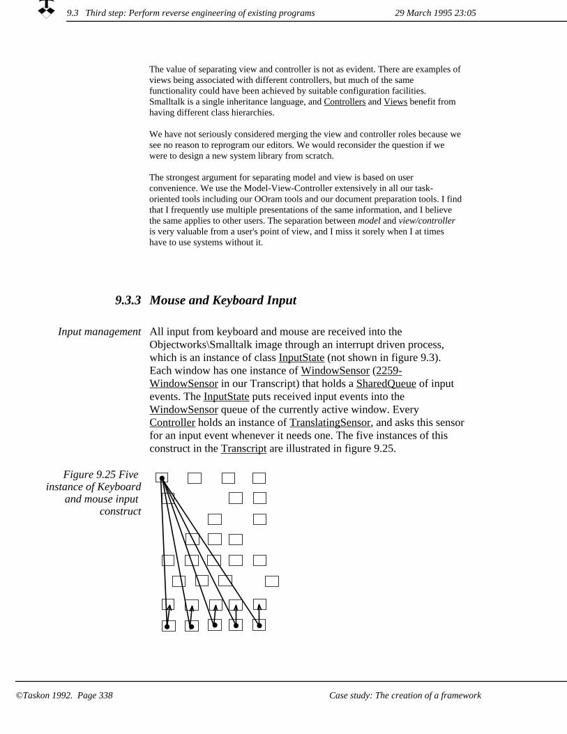
The value of separating view and controller is not as evident. There are examples of views being associated with different controllers, but much of the same functionality could have been achieved by suitable configuration facilities. Smalltalk is a single inheritance language, and Controllers and Views benefit from having different class hierarchies.
We have not seriously considered merging the view and controller roles because we see no reason to reprogram our editors. We would reconsider the question if we were to design a new system library from scratch.
The strongest argument for separating model and view is based on user convenience. We use the Model-View-Controller extensively in all our task-oriented tools including our OOram tools and our document preparation tools. I findthat I frequently use multiple presentations of the same information, and I believe the same applies to other users. The separation between model and view/controller is very valuable from a user's point of view, and I miss it sorely when I at times have to use systems without it.
Mouse and Keyboard Input9.3.3
Input management All input from keyboard and mouse are received into the Objectworks\Smalltalk image through an interrupt driven process, which is an instance of class InputState (not shown in figure 9.3). Each window has one instance of WindowSensor (2259-WindowSensor in our Transcript) that holds a SharedQueue of input events. The InputState puts received input events into the WindowSensor queue of the currently active window. Every Controller holds an instance of TranslatingSensor, and asks this sensorfor an input event whenever it needs one. The five instances of this construct in the Transcript are illustrated in figure 9.25.
Figure 9.25 Five instance of Keyboard
and mouse input construct
29 March 1995 23:059.3 Third step: Perform reverse engineering of existing programs
Case study: The creation of a framework©Taskon 1992. Page 338

We will now discuss two role models that explain these input facilities. We will see that the models give a nice overview of the phenomena which would be hard to get by studying the classes.
There are two different chains of objects in figure 9.3 which are of interest to our current discussion: the visual component objects going from top to bottom, such as 3822-ScheduledWindow, 5116-BorderDecorator, 9943-BorderedWrapper, 12188-ScrollWrapper, 9795-TextCollectorView. Another chain of objects go from bottom totop, such as 3003-ParagraphEditor (aController), 610-TranslatingSensor, 2259-WindowSensor. There are similar chains for the menu bar and the scroller buttons.
One of the responsibilities of the objects of the down chain is to keep track of the coordinate transformations between the window's coordinate system and the coordinate system of the TextCollectorView, as described in 9.3.1: The Container-Component Hierarchy. We will build on this functionality in the TranslatingSensor Initialization Model.
Main Input Role Model
The first model is the Main Input Model, which describes how the keyboard and mouse input is made available to the Controller. The second model is the TranslatingSensor Initialization Model, which describes how the TranslatingSensor is set to provide the required coordinate transformations.
Main Input Role Model
Figure 9.26 Area of concern
This model describes the objects employed to let Controllers read mouse and keyboard input.
All the five instances of the input construct highlighted in figure 9.25 are represented by the three input roles of figure 9.27.
9.3 Third step: Perform reverse engineering of existing programs29 March 1995 23:05
©Taskon 1992. Page 339Case study: The creation of a framework

Figure 9.27 Collaboration view
of Main Input Model
s
inp
ws
ws
WindowSensor
Controller
The WindowSensor role has queues for metaInput, keyboardInput, and damage. Instances are also responsible for handling events for their window. Mouse coordinates are translated into the window's coordinate system.
TranslatingSensor
Object responsible for capturing and processing input from the user.
The TranslatingSensor role is an InputSensor that translates mouse coordinates into a client's local coordinate system.
InputState
The InputState role runs a separate process and accepts input events from the platform. It queues keyboard events and flattens the mouse motion and mouse button state into booleans for polling InputSensors. Keyboard shift, control and meta are also flattened.
S
S
A
TranslatingSensor Initialization Model
Figure 9.28 Area of Concern
The Area Of Concern is to initialize the TranslatingSensor coordinate transformation of cursor positions. It uses parts of the Container-Part role model, to do so as illustrated in the collaboration view and the scenario.
s
sw
cv
swws ws
TranslatingSensor<ControllerglobalOrigin:
ScheduledWindow
Controller<ViewflushCoordinateCachessetSensorFromView
WindowSensor<ControllertranslatingSensor
View<ControllerlocalPointToGlobal:topComponent
ScheduledWindow<Controllersensor
WindowSensor
ViewControllerTranslatingSensor
Figure 9.29 TranslatingSensor
Initialization Collaboration view
with important messages
9.3 Third step: Perform reverse engineering of existing programs 29 March 1995 23:05
Case study: The creation of a framework©Taskon 1992. Page 340

Controller View ScheduledWindow
WindowSensor
TranslatingSensor
flushCoordinateCaches
topComponent
sensor
translatingSensor
localPointToGlobal: 0@0
globalOrigin: aPoint
Figure 9.30 Scenario:
TranslatingSensor Initialization
An interesting feature of this interaction is the central position of the Controller. The Controller asks the view for its topComponent, and gets a temporary port to the ScheduledWindow. It then asks the ScheduledWindow for its sensor, and gets another temporary port to the WindowSensor. It can then finally ask the WindowSensor for a new translatingSensor, which it can give the required coordinate transformation and install.
We see that the Controller knows a great deal about the complete structure of objects. This is generally not a good idea, because it makes it hard to change the structure. I think I would have preferred to let the Controller ask the View for a new TranslatingSensor and let this request pass up the Container-Component chain.
Ports are by default implemented as instance variables, but the Controller's sw and ws ports are in this case implemented as temporary variables. They still have to be shown as Controller ports in the role model, because the Controller sends messages through them.
9.3 Third step: Perform reverse engineering of existing programs29 March 1995 23:05
Case study: The creation of a framework ©Taskon 1992. Page 341

The Scroller role model9.3.4
Scrolling Scrolling is needed when the rectangle allocated to a View may be insufficient to show all of its contents. There is one instance of the scrolling construct in the Transcript as indicated in figure 9.31. Scrolling takes place when the user pushes the up or down scroll button, or slides the scrollbar slider. All three are implemented as specializations of the Model-View-Controller. We will show the design of the scrollbar as an illustration. The 12188-ScrollWrapper in figure 9.3 is the model object; 444-Scrollbar is the view object; and 15219-ScrollbarController is the controller object. The corresponding role model is shown in figure 9.32, which also shows the synthesis relationship between this model and the basic MVC model.
Figure 9.31 One instance of the
Scrolling construct
29 March 1995 23:059.3 Third step: Perform reverse engineering of existing programs
©Taskon 1992. Page 342 Case study: The creation of a framework

Figure 9.32 The Scrollbar role model is derived from MVC m
md
v
c
in
v
c
out mds
min
out
ScrollbarController
Scrollbar
ScrollbarController implements the control mechanism for Smalltalk's standard look and feel. If the cursor is within the marker portion of the scrollbar when the button goes down, the marker will follow the cursor. If the cursor is outside the marker portion, the marker will page toward the cursor.
ScrollWrapper
Scrollbar is a slider that permits a variable-sized bubble, and is used to put scrollbars on a view.
User
A ScrollWrapper is a Container (See Container-Component role model) that translates the coordinate system for their Component.
Controller
View
ModelUser
The message flow which takes place when the user moves the scrollbar is illustrated in the scenario in figure 9.33:
The activity starts when the User moves the scollbar (scrollAbsolute).
1.
The ScrollbarController senses this movement. It computes relative displacement in model coordinates (mapToDataSpace:, dataExtent). The ScrollbarController notes the displacement of the scrollbar. It then sends the scrollVertically: message to the ScrollWrapper.
2.
The ScrollWrapper scrolls itself by changing its coordinate transformation. (The ScrollWrapper also redisplays itself and its component. This display is done with the new transformation, andthe contents appears scrolled. This is not shown in the scenario.)
3.
4. The Scrollbar (view) redisplays itself. The scrollbar position mustbe updated regardless of the cause of the stimulus causing the scrolling action. This is taken care of by the changed-update mechanism: Whenever the ScrollWidget changes its scroll offset, it sends a changed-message to itself which causes an update:with:from: message to be sent all dependents, including the Scrollbar. The Scrollbar then computes new values for the size and position of its slider from the visibleExtent, dataExtent and scrollOffset of the ScrollWidget so that it can redisplay itself.
9.3 Third step: Perform reverse engineering of existing programs29 March 1995 23:05
©Taskon 1992. Page 343Case study: The creation of a framework

Figure 9.33 Scenario: Scroll vertically, using
scrollbar
User ScrollbarController Scrollbar Scroll
Wrapper
scrollAbsolute
mapToDataSpace:
dataExtent
scrollOffset
scrollVertically:
update:with:from:
visibleExtent
dataExtent
scrollOffset
User Controller View Model
29 March 1995 23:059.3 Third step: Perform reverse engineering of existing programs
©Taskon 1992. Page 344 Case study: The creation of a framework

Fourth step: Specify the new framework9.4
In a nutshellThe new framework was specified to combine functionality that had been supportedby different frameworks in the past.
Our consumers are Taskon programmers who are experts within their application domain and who want to create new editors with a minimum of hassle.
In the past, we have provided separate frameworks for the visual component functions much as we have described them in the above reverse engineering reports. Each framework is reasonably simple, but the sum is quite formidable so that the creation of new editors has been a job for experts.
We now want to explore if the frameworks can be combined into a single one which is so simple to use that even a novice Smalltalk programmer can program a new editor with ease and confidence.
We want a single framework
The general requirements of section 9.1 can be augmented by some specific technical issues:
Model-View-Controller. We need to improve the standard MVC solution to ensure safe synthesis in all situations.
1.
2. Change management. We have recurring problems with managing the redisplay caused by changes in the underlying information. We sometimes lose a required redisplay, and the screen sometimes flashes unnecessarily because of multiple redisplays. The new framework shall offer a simple mechanism so that the application programmer does not need the intricacies of changed-update as part of his active competence.
3. Configurability. We have a large number of different editors (view-controller pairs) and want to be able to reuse them as leaf components in any component hierarchy. It shall, for example, bepossible to use a drawing as a table cell and a table as a drawing element.
Coordinate transformations. It is hard to think in several coordinate systems simultaneously. The application programmersshall only be required to think in terms of the application's coordinate system.
4.
9.4 Fourth step: Specify the new framework29 March 1995 23:05
Case study: The creation of a framework ©Taskon 1992. Page 345

Scrolling. Scrolling is a fairly complex operation involving many objects and should be highly optimized. We want scrolling to be part of the internal details of the framework so that application programmers can always get it and never need to construct it. All visual components shall be scrollable at the discretion of the application programmer, and it shall be possible to configure scrolled components within other scrolled components.
5.
29 March 1995 23:059.4 Fourth step: Specify the new framework
Case study: The creation of a framework©Taskon 1992. Page 346

9.5 Fifth step: Document the framework as patterns describing how to solve problems
In a nutshellIn this step, we give a number of patterns that describe how a consumer apply the Tool framework.
We assume the reader of the patterns to be thoroughly familiar with the solution technicalities. This is in accordance with Alexander's patterns, which are short and to the point. The patterns give sufficient information for the expert reader; the non-expert can study the solution logic of the sixth step to become one.
We assume pattern user to be expert
An example is our use of the terms actualBounds, virtualBounds and changeParameter in the patterns given below. They will be explained in section 9.6: Describe the framework's design and implementation ; where generalists will find a first level of explanation.
We here give six example patterns which relate to the Tool framework. The Tool pattern builds on smaller patterns; the Tool framework builds on smaller frameworks. We describe the following patterns:
1. The Tool
Fixed Proportion Tool Layout2.
3. Flexible Tool Layout
The Controller4.
The Model Object5.
The View6.
Pattern 1: The Tool9.5.1
When to use A tool is a constituent of the user information environment and appears as a coordinated set of editors within a rectangle on the screen.
You use this Tool framework when the following conditions are satisfied:
9.5 Fifth step: Document the fram...ribing how to solve problems29 March 1995 23:05
Case study: The creation of a framework ©Taskon 1992. Page 347
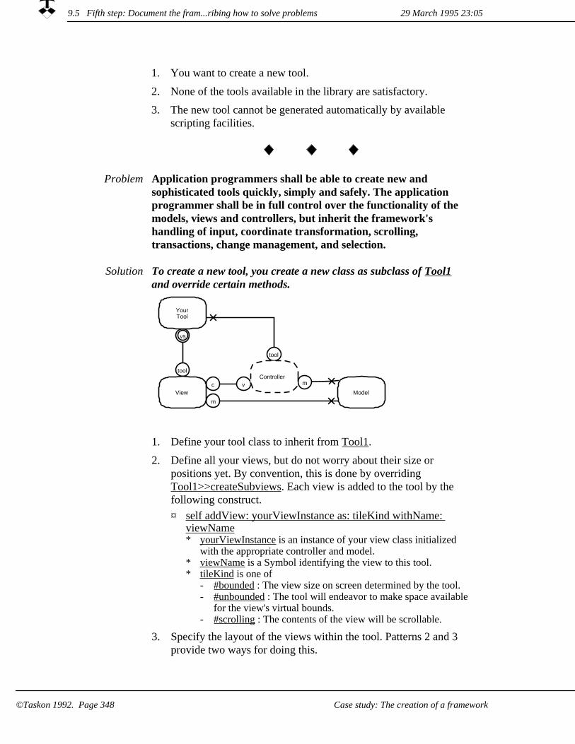
You want to create a new tool.1.
2. None of the tools available in the library are satisfactory.
The new tool cannot be generated automatically by available scripting facilities.
3.
Problem Application programmers shall be able to create new and sophisticated tools quickly, simply and safely. The application programmer shall be in full control over the functionality of the models, views and controllers, but inherit the framework's handling of input, coordinate transformation, scrolling, transactions, change management, and selection.
To create a new tool, you create a new class as subclass of Tool1 and override certain methods.
Solution
tool
vs
tool
m
m
c v
YourTool
View
Controller
Model
1. Define your tool class to inherit from Tool1.
Define all your views, but do not worry about their size or positions yet. By convention, this is done by overriding Tool1>>createSubviews. Each view is added to the tool by the following construct.
2.
self addView: yourViewInstance as: tileKind withName: viewName
¤
yourViewInstance is an instance of your view class initialized with the appropriate controller and model.
*
* viewName is a Symbol identifying the view to this tool.* tileKind is one of
#bounded : The view size on screen determined by the tool.-#unbounded : The tool will endeavor to make space available for the view's virtual bounds.
-
- #scrolling : The contents of the view will be scrollable.
Specify the layout of the views within the tool. Patterns 2 and 3 provide two ways for doing this.
3.
29 March 1995 23:059.5 Fifth step: Document the fram...ribing how to solve problems
Case study: The creation of a framework©Taskon 1992. Page 348

Specify tool-defined menus, if any.4.
¤ Controllers can ask the tool for the yellowMenu with the following message, which either returns a menu or nil:
self menuFromTool*
¤ Construct the selector for the Tool method from the corresponding view name as shown below. Write the corresponding method so that it returns a menu or nil.* #<viewName>Menu. E.g., #editorMenu
Specify coordinated selection, if any.5.
¤ Controllers report selection changes to the tool by the expression:* self hasSelected: (Collection of aModelObject)
Construct the selector for the Tool method from the corresponding view name as shown below. Write the corresponding method to handle the selection.
¤
#<viewName>HasSelected: e.g., editorHasSelected: (aCollection of aModelObject)
*
The tool may force selection in an editor by sending¤self viewNamed: viewName select: (Collection of aModelObject)
*
References Use Pattern 2: Fixed Proportion Tool Layout (p. 349??) to specify simple, proportional layouts, or Pattern 3: Flexible Tool Layout (p. 350??) for full freedom in layout specification. See also Patterns 4: The Controller (p. 352??), 5: The Model Object (p. 353??) and 6: TheView (p. 354??).
Pattern 2: Fixed Proportion Tool Layout9.5.2
You use this pattern when your tool layout is defined by simple proportions.
This pattern is one of the alternative specifications of the layout of 1: Tool (p. 347??)
When to use
The application programmer shall be able to simply specify the layout of a tool in terms of the available screen area.
Problem
9.5 Fifth step: Document the fram...ribing how to solve problems29 March 1995 23:05
Case study: The creation of a framework ©Taskon 1992. Page 349
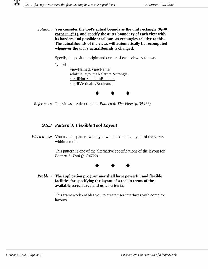
Solution You consider the tool's actual bounds as the unit rectangle (0@0 corner: 1@1), and specify the outer boundary of each view with its borders and possible scrollbars as rectangles relative to this. The actualBounds of the views will automatically be recomputed whenever the tool's actualBounds is changed.
Specify the position origin and corner of each view as follows:
self viewNamed: viewName relativeLayout: aRelativeRectanglescrollHorizontal: hBoolean scrollVertical: vBoolean.
1.
The views are described in Pattern 6: The View (p. 354??).References
9.5.3 Pattern 3: Flexible Tool Layout
You use this pattern when you want a complex layout of the views within a tool.
This pattern is one of the alternative specifications of the layout for Pattern 1: Tool (p. 347??).
When to use
Problem The application programmer shall have powerful and flexible facilities for specifying the layout of a tool in terms of the available screen area and other criteria.
This framework enables you to create user interfaces with complex layouts.
9.5 Fifth step: Document the fram...ribing how to solve problems 29 March 1995 23:05
Case study: The creation of a framework©Taskon 1992. Page 350

Solution You override the Tool1 method suggestedWidth:height: which is called every time the tool is to be allocated a new actualBounds and when other conditions have changed.
The suggested width and height specify the space that will be made available to the tool, nil values indicate that the container will adapt to whatever value you choose (e.g., by scrolling).
This pattern gives you full control at the cost of writing a somewhat complex method.
Specify the layout of the views within the tool by overriding
Tool1>>suggestedWidth: wIntegerOrNil height: hIntegerOrNil1.
¤ Default virtualBounds for the tool is the Rectangle enclosing its components, but you may set a different value after you have completed the layout by:
self virtualBounds: aRectangle.*
Resize and position each view. The views may be handled in any sequence, and the position and size of a view may be made dependent on the virtualBounds of other views after theyhave been positioned (all geometry in the following messages are in the tool's coordinate system):
¤
* You must offer the view an opportunity to resize itself:self
viewNamed: viewNamesuggestedWidth: wIntegerOrNil height: hIntegerOrNil.
-
You must position the view:*- self
viewNamed: viewNameorigin: originPoint
References The views are described in Pattern 6: The View (p. 354??).
9.5 Fifth step: Document the fram...ribing how to solve problems29 March 1995 23:05
©Taskon 1992. Page 351Case study: The creation of a framework

Pattern 4: The Controller9.5.4
You use this pattern when you want user command activities to be performed within a transaction. Views redisplay themselves once at the end of a transaction when the model is in a consistent state.
This is the default pattern for controller objects which you use in Pattern 1: The Tool.
When to use
Problem The Controller is responsible for handling all user input. This pattern gives it the added responsibility to ensure that all activities that lead to model attribute changes shall be performed within a transaction.
All commands that change one or more model attributes must be executed within a transaction. The transaction shall be activated as close to the user interaction code as possible:
Solution
1. TransactionManagerinTransactionDo: [<code modifying model attributes>]
TransactionManager is a global variable, the sole instance of class TransactionManager1.
¤
v
c
mtm
s
TransactionManager
Controller Model
TranslatingSensor
View
Other patterns may be made which specialize this one, but they are not discussed here.
References
29 March 1995 23:059.5 Fifth step: Document the fram...ribing how to solve problems
©Taskon 1992. Page 352 Case study: The creation of a framework

Pattern 5: The Model Object9.5.5
When to use You use this pattern when you want to program model objects and none of its specializations are appropriate.
This is the default pattern for model objects which you use for Pattern1: The Tool (p. 347??), and the corresponding programs are parts of the Tool framework.
Problem Views send messages to the model to obtain the current values of its attributes, and may cache the results on the screen or in a variable. It is the responsibility of the model to inform its views whenever messages will return a new value.
Solution You capture model attribute changes and map these changes to the externally available interrogation messages.
m
m
ModelObject
View
Controller
Define your new model class as a subclass of Model1. Then do the following:
Program the model functionality.1.
All methods which modify one or more object attributes shall send this message
2.
¤ selfchangedAttributes: (Array of attribute names)areas: aCollectionOfRectanglesOrNilThe default attribute names are the instance variable names, but you may select any names which reflect the model semantics as long as you map them to the corresponding message selectors in changeParameterAssociations.
*
29 March 1995 23:05 9.5 Fifth step: Document the fram...ribing how to solve problems
©Taskon 1992. Page 353Case study: The creation of a framework

3. Define the following private class method which associates the name of each attribute in your class with the selectors of messages whose return value depend on the attribute:
changeParameterAssociations" Associations between change attributes and method
selectors. "^(super changeParameterAssociations)
add: <attributeNameSymbol>-> #(<list of message selectors>);
<repeat for all attributes of this class>;yourself.
¤
* The Taskon Browser text command generateChParAssociations creates a default method which you must check carefully.
The Taskon Quality Checker will flag implementations of changeParameterAssociations which are missing or which do notmention all attributes specified in the changedAttributes:areas: methods.
4. TransactionManager allChangeInitializations must be executed to make the changeParameterAssociations take effect.
References Other patterns may be made which specialize this one, but they are not discussed here.
Pattern 6: The View9.5.6
When to use You use this pattern when you want to program view objects and when none of its specializations are appropriate.
This is the default pattern for view objects which you use for Pattern 1: The Tool (p. 347??).
The view caches information it has obtained from the model, usually in the form of a picture on the screen. The view receives the message update1: towards the end of the transaction if the model has changed. Make sure that the view is updated exactly as needed and no more.
Problem
9.5 Fifth step: Document the fram...ribing how to solve problems 29 March 1995 23:05
Case study: The creation of a framework©Taskon 1992. Page 354

Solution The ChangeHolder parameter has accumulated information about all the model changes that have occurred in this transaction. The ChangeHolder also accumulates information about required redisplays. These accumulated changes are merged and performed at the end of the transaction.
Make your View class inherit from View1. Override update1, and determine required redisplays and possible changes to the virtualBounds from the current viewChangeHolder:
Send the following message if you want to order a redisplay:1.
self changeHolder invalidate: damageRectangle¤
2. Send the following message if you want to change the virtualBounds of the view:
¤ self virtualBounds: aRectangle
Send the following message if you want the accumulated change information to take effect without waiting for the end of the transaction:
3.
self commitChanges¤
vch
v
cv
ct
cn
mViewController Model
ViewChangeHolder
Container
References Other patterns may be made which specialize this one, but they are not discussed here.
9.5 Fifth step: Document the fram...ribing how to solve problems29 March 1995 23:05
©Taskon 1992. Page 355Case study: The creation of a framework
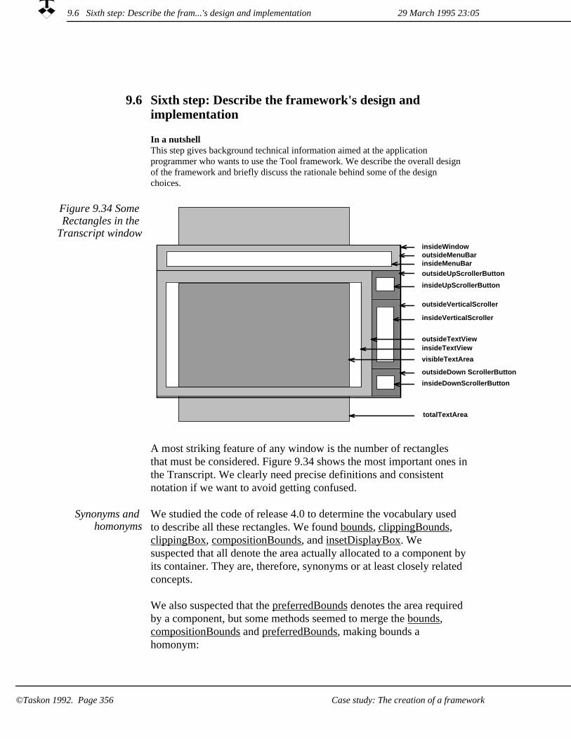
Sixth step: Describe the framework's design and implementation
9.6
In a nutshellThis step gives background technical information aimed at the application programmer who wants to use the Tool framework. We describe the overall design of the framework and briefly discuss the rationale behind some of the design choices.
insideMenuBaroutsideMenuBar
outsideTextView
outsideUpScrollerButton
insideTextView
outsideVerticalScroller
visibleTextArea
totalTextArea
insideUpScrollerButton
insideVerticalScroller
outsideDown ScrollerButton
insideDownScrollerButton
insideWindow
Figure 9.34 Some Rectangles in the
Transcript window
A most striking feature of any window is the number of rectangles that must be considered. Figure 9.34 shows the most important ones inthe Transcript. We clearly need precise definitions and consistent notation if we want to avoid getting confused.
Synonyms and homonyms
We studied the code of release 4.0 to determine the vocabulary used to describe all these rectangles. We found bounds, clippingBounds, clippingBox, compositionBounds, and insetDisplayBox. We suspected that all denote the area actually allocated to a component byits container. They are, therefore, synonyms or at least closely related concepts.
We also suspected that the preferredBounds denotes the area required by a component, but some methods seemed to merge the bounds, compositionBounds and preferredBounds, making bounds a homonym:
29 March 1995 23:059.6 Sixth step: Describe the fram...'s design and implementation
Case study: The creation of a framework©Taskon 1992. Page 356

VisualPart>>bounds^container == nil
ifTrue: [self preferredBounds]ifFalse: [container compositionBoundsFor: self]
CompositePart>>compositionBoundsFor: aVisualComponent^aVisualComponent preferredBounds
Our main rectangles It is quite likely that we did not fully understand the ideas behind the visual component hierarchy, but we felt a strong need for some precisely defined words which we could use consistently throughout the framework. We defined the following three notions:
virtualBounds. The rectangular area required by a visual part. All visual parts must at all times be able to answer their virtualBounds. A container may ask its components for their virtualBounds, but we explicitly prohibit a component from asking its container to avoid infinite recursion. (virtualBounds is roughly equivalent to preferredBounds.)
1.
2. actualBounds. The rectangular area allocated to a component by acontainer. A component without a container has actualBounds = (0@0 corner: 0@0). A component may at any time ask its container for its actualBounds, so the component need not remember it. It is, therefore, dangerous and meaningless for a container to ask its components for its actualBounds.
dataBounds. The rectangular area occupied by the data in a modelobject. This attribute is only defined where appropriate.
3.
VisualPart2 is the superclass of all our visual part classes. An extract of the class hierarchy is as follows:
Our main classes of visual parts
29 March 1995 23:05 9.6 Sixth step: Describe the fram...'s design and implementation
Case study: The creation of a framework ©Taskon 1992. Page 357

VisualPart2
1. SimpleContainer2 defines a subroot in the visual part hierarchy that holds at most one component.
¤ View2 is the Taskon View superclass; all Taskon views shall be subclass of this or equivalent.
MarginTool1. A multi-media tree editor, an example is given in figure 12.5 on page 440??.
*
¤ Tile2 defines the only visual parts which are responsible for coordinate transformations. A Tile positions its component within its container and transforms the relevant parameters and return values of messages being passed up and down the visual hierarchy chain.
BoundedTile2 defines a Tile whose virtualBounds is identical to the virtualBounds of its part.
*
UnboundedTile2 defines a Tile whose virtualBounds is the area allocated by its Container (A larger Part will be clipped.)
*
ScrollingTile2 defines a Tile which is able to vary its coordinate transformation to effect scrolling of its component.
*
¤ EdgeWidget1 is the common superclass for all edge widgets such as scrollers and menu bars. The EdgeWidget plays the roles of both Controller and View, while a scrollable component such as a ScrollingTile plays the role of model.
Scroller1 defines horizontal and vertical scrollbars.*ScrollerButton1 defines the up, down, left and right scroll buttons.
*
2. CompositeContainer2 defines a subroot in the visual part hierarchy that holds any number of named components.
Tool2 defines CompositeContainers that manage one or more views which may be decorated with possible Widgets for menu and scrolling, and are laid out in a reasonably stable pattern within the Tool's actualBounds. Subclasses define specific tools.
¤
Standard MVC unsafe
The standard changed-update mechanism in the Model-View-Controller works nicely in simple cases when the model consists of a single object and the user command leads to the modification of a single attribute. But the mechanism may cause difficulties in more complex situations:
29 March 1995 23:059.6 Sixth step: Describe the fram...'s design and implementation
Case study: The creation of a framework©Taskon 1992. Page 358
Multiple display for multiple attribute changes. Our general rule is that any method which modifies an object should also send the self changed- message, which leads directly to an update-messagebeing sent to all views, which again leads to the views redisplaying themselves. If the user command leads to several attribute changes, the views will redisplay themselves several times, once for each attribute. This takes time and is disturbing to the user.
1.
2. Model may be inconsistent in the middle of a modification activity. The model may be a structure of objects such as a doublylinked list. A structure change will involve several objects and several methods, and the model is likely to be inconsistent until the modification activity is completed. If each method that performs part of the structure modification sends a self changed: message, the views will try to display an inconsistent model with possible catastrophic results.
3. The model programmer loses control when sending an update-message. We have, in certain very special cases, found it convenient to program a chain reaction: A user command leads toa model change, which leads to a view update. The view update method sends a new attribute modification message to the model. This is a new stimulus in the MVC model which is sent while the system is busy performing the previous activity. (FOOTNOTE: This is exactly what we defined as unsafe synthesis in chapter 3??.)
In the basic changed-update construct, the nature of the change is communicated from the model to the view through a Symbol parameter. We have tried various conventions about the choice of Symbols, but we often ended up with special choices based on our knowledge about the exact needs of the views. We did not like this, because we wanted to maintain maximum independence between model and view.
Improved parametersto the changed-
update messages
This led us to reconsider the exact nature and purpose of the changed-update construct. We made the following observations:
1. Universe of discourse is message set. The universe of discourse between view and model is the set of messages that the view employs to retrieve information from the model.
2. The view caches model information. The view caches model information and needs to be told about model changes so that it can update the caches. (The most common form of cache is in the display memory which controls the display.)
9.6 Sixth step: Describe the fram...'s design and implementation29 March 1995 23:05
Case study: The creation of a framework ©Taskon 1992. Page 359

3. The view needs to know the messages that return a new value. The real meaning of an update message is that the model tells the view that "one or more of my messages will now return a different value"; the view programmer needs to know which messages have been affected so that he can take appropriate action.
4. The model knows which attributes have been changed. We tried tolet the model programmer specify the list of affected selectors as aparameter to the self changed: message, but this was almost impossible to maintain correctly when new messages were added to the model's interface. We therefore decided to let the parameterto changed: be a list of affected attributes, where an attribute may be anything the model programmer decides to consider as such. (The choice of attribute names is invisible outside the class).
changeParameterAssociation maps attributes to messages. The view wants to see message selectors; the model wants to report the names of changed attributes. We clearly need to create a map between the two. Attempts at creating this map automatically have all failed, and we require the application programmer to enumerate all attributes and to associate the affected selectors with each attribute. This is done in the private class method changeParameterAssociations.
The form of the changeParameterAssociations method has been chosen so as to make it easy to write and check the mappings. A special initialization method, Object allChangeInitializations, transforms this information into a Dictionary which is optimized for fast look-up. (This Dictionary is stored in an Object class instance variable called changeAttributes.)
5.
Damage areas. We also considered adding a general parameter, the nature of which could be decided by the programmer. But this brought us right back to the original difficulties. Reverse engineering of our current solutions has shown that we only need one special parameter, namely the areas affected by the change in the attribute.
This damageAreas parameter is meaningful if the model semantics includes a sense of geometry. The effects of an attributechange may then be limited to certain areas within the area covered by the model. We cannot quite decide if this is a profound truth about changed-update or if it is just a hack, but we include it in our design anyhow.
6.
29 March 1995 23:059.6 Sixth step: Describe the fram...'s design and implementation
©Taskon 1992. Page 360 Case study: The creation of a framework

The ChangeHolder. We finally created a new class for the parameter to the update message. The central feature is that the view can ask this parameter if specified selectors are affected by the current change, but it also holds information about the originating model object and the associated damage areas, if any.
7.
8. Models and views have ChangeHolders. Every model object has aChangeHolder where information about model changes is accumulated. Every view object has a ChangeHolder which holdsinformation about interesting model changes and outstanding view operations.
The Tool object is the object which controls the layout of the Tool's editors (view-controller pairs) and coordinates their behavior. This object has been a rover in our architecture. We have tried letting a controller play the Tool role, and we have tried letting the Tool objectbe a separate object outside the VisualPart hierarchy. Our current solution is to let the Tool be a Container object because it is responsible for an area of the screen and manages a number of Components. A general role model showing the Tool's position in theVisualPart structure is shown in figure 9.35.
The tool object is part of the visual
component hierarchy
9.6 Sixth step: Describe the fram...'s design and implementation29 March 1995 23:05
Case study: The creation of a framework ©Taskon 1992. Page 361

Figure 9.35 The VisualPart
architecture showingthe position of the
Tool role
cv
cp
ct
part
ct
m
ch
v
tlsct
s dpstl
cp
bou
cp
ct
vie
too
s
m
tls
ct
cps
con
tra
tra
mod
tra
vie
mch
m
ds
Container
Tool
Tile
WidgetComposite
BoundedTile
ScrollingTile
ScrollActuator
ViewController Model
TranslatingSensor
TranslatingSensor
ViewChangeHolder
ModelChangeHolder
TransactionManager
ModelViewCon-troller
Tool
Activity phases controlled by
transactions
We have introduced transactions to solve the problems with views trying to display inconsistent models, and with multiple, redundant display operations. The transaction also controls the persistent storage of model objects, but this does not belong to our current discussion.
29 March 1995 23:059.6 Sixth step: Describe the fram...'s design and implementation
Case study: The creation of a framework©Taskon 1992. Page 362

Transactions are controlled by the TransactionManager, the sole instance of the class TransactionManager1. Only one transaction can be active at any time; there is no nesting. The activity is performed as a block in the TransactionManager; it is called by the Controller as described in Pattern 4: The Controller. A transaction rearranges the actions of a user command activity into four phases:
1. Model change. One or more messages from a controller cause the model objects to modify their attributes. The methods that do the actual modifications report this by sending the message self changedAttributes: attributeList damage: areaList. The information is temporarily accumulated in the model object's ChangeHolder.
2. View update. The components in the visual component hierarchy receive an update1 message in prefix order, starting with the ScheduledWindow in the root. All relevant information is available in the view's ChangeHolder when it receives the update1 message. The application programmer must override this method and do whatever is needed:
Changes to the view's virtualBounds must be reported to its container by self changedBoundsFrom: oldBounds.
¤
¤ Required display operations are stored in the ChangeHolder where they are retained until the next phase: self changeHolder invalidate: aRectangle.
View display. The visual component hierarchy is traversed to ensure the display of required areas once and once only.
3.
29 March 1995 23:05 9.6 Sixth step: Describe the fram...'s design and implementation
©Taskon 1992. Page 363Case study: The creation of a framework

Seventh step: Inform the consumer community9.7
In a nutshellIn this case, the consumers are ourselves. But we still need a systematic information and training program.
In our case, the main part of this step consisted of a number of short seminar and discussion groups. In addition, the Tool framework documentation was given to every programmer and also made available electronically.
The Taskon programmer's procedures were modified to check conformance with the rules of the framework. While non-conformance is permissible in special cases, programmers are encouraged to follow the framework as closely as possible.
9.7 Seventh step: Inform the consumer community 29 March 1995 23:05
Case study: The creation of a framework©Taskon 1992. Page 364

Chapter 10Organizing for software productivity
This chapter is mainly written for the software manager and businessperson who is willing to consider new ways to create and deploy software. We present the idea of a value chain: somebody creates something that is of value to somebody else, who creates something that is of value to somebody else, and so on up to the end user who applies software to perform a valuable task.
An industrial approach to software productionLarge-Scale Production of Intelligent Network ServicesLarge-Scale Production of Customized Business Information Systems
29 March 1995 23:05
Organizing for software productivity ©Taskon 1992. Page 365

An industrial approach to software production10.1
In a nutshellSoftware life cycle models tell us what happens to a piece of software and when it happens. We expand our interest with a third dimension: who makes it happen.
We believe that the people who contribute their skills to the creation and deployment of software should be organized in a value chain. The guiding principleshould be that while the qualifications of the people on the different layers will be different, the individual qualification requirements shall be realistic in terms of a large and distributed organization plan. The professionals performing the tasks on each layer shall be supported by a combination of technologies, procedures and tools.
One of the great promises of object orientation is reuse, but we must organize ourselves properly to realize its potential. We present the idea of a value chain: somebody creates something that is of value to somebody else, who creates something that is of value to somebody else, and so on up to the end user who applies software to perform a valuable task.
We must organize properly to realize
reuse potential
On each layer, there are people who employ the results created by the people on the layer below and provide results for the people on the layer above. The technology and techniques applied at each layer must be tailored to the personnel who populate it, their goals, tasks, working conditions, preferences and competence.
Different value chains for different kinds of software are likely to emerge as the industry matures. We expect to find a marketplace with a network of suppliers, each specialized to cater to a particular clientele.
The challenge to the software manager and businessperson is to find good answers to two questions: What will be our role in the future software industry? And how do we get from here to there?
We will not pretend that we have the final answers to either of these questions, but we have worked on them for more than ten years. In this chapter, we give a report on a structure for the telecommunications intelligent network services industry, and also a report on how to organize the creation and deployment of business information systems.
10.1 An industrial approach to software production 29 March 1995 23:05
©Taskon 1992. Page 366 Organizing for software productivity

Software life cycle models are commonly used to describe the important events in the life of a piece of software. A model may, for example, distinguish between system specification, design, implementation, testing, installation, and maintenance. There are many variants of this model, but most of them have one thing in common: they describe the software life cycle from the point of view of the program developer. Just consider the apparently innocent word maintenance. It covers both bug fixing and minor software improvements. Bug fixing could involve a user who discovers a software irregularity, a systems operator in the user organization who passes a bug report to the vendor's customer support person, who reports the bug to the head of the software development team, who allocates it to a responsible programmer, who fixes the bug and returns a program patch along the same path.
Extend the life cycle model with an actor
dimension
We want to extend the traditional life cycle model to describe all the different people and all the activities that contribute to the final value to the end user.
We could say that traditional life cycle models have two dimensions: What and when. We extend the models with who as a third dimension.This permits us to describe the software life cycle not only from the programmer's point of view, but also from the point of view of other people such as the provider of reusable components, the distributor, and the end user.
What, when, who
The relationships between the people on the different layers are producer-consumer relationships, because the raison d'ètre of the people on one layer is to produce value for the people on the layer above them. We call the layers along this dimension a value chain asillustrated in figure 10.1. Each layer is populated by a team with defined responsibility and skills. The team builds on the results from the team below it and provides value to the team above.
10.1 An industrial approach to software production29 March 1995 23:05
Organizing for software productivity ©Taskon 1992. Page 367

Figure 10.1 The value chain End user
Layer N
Layer N-1
Layer N-2
HardwareLayer 0
We will first describe the characteristics of a single layer, and then discuss the nature of the whole value chain.
Production facilities for layer n+1= Deliverables from layer N
Production facilities for layer N= Deliverables from layer N-1
Work process in layer N
Figure 10.2 A layer in the value chain get
value from below and provide value to
layer above
Figure 10.2 shows a generic specification of an abstract layer. The layer has its own tasks, work processes and production facilities. The work processes can be formal or informal according to the culture andpreferences prevalent on that particular layer. The layer specification must be augmented by the special requirements associated with a concrete layer.
Need effective work process
A set of production facilities will be available; these facilities will include work process guidelines that separate the total work into manageable tasks, techniques to perform these tasks, and computer-based tools that help perform the tasks. The facilities of a given layer must be adapted to the interests and qualifications of the actors of that layer.
Supported by production facilities
29 March 1995 23:0510.1 An industrial approach to software production
©Taskon 1992. Page 368 Organizing for software productivity

The actors populating a given layer have unique responsibilities and corresponding competence and interests. The production facilities for the actors on every layer in the value chain should be designed at leastas carefully as we design the end user systems. The current tendency to try and provide a common environment that satisfies all needs will result in solutions that are too complex to satisfy anybody. The guiding principle should be that the qualifications of the actors on the different layers must be realistic in terms of real people. Their goals, qualifications, tasks, and production facilities must all be in harmony.
People form the mostessential part of a
layer
A layer creates a certain kind of value. The products delivered from one layer constitute the libraries and other production facilities employed on the layer above it. The success criterion of the people populating the layer (the supplier) is the satisfaction of the consumers on the next layer up. The actors who populate a layer must, therefore, understand the qualifications and requirements of their clients.
The deliverables constitute the
product
There should be "firewalls" between
layers
An important principle in our architecture is that we assume actors to be hostile, some times by intent, but usually by ignorance of details which are of no interest to them. The production facilities for any layer must, therefore, be secure: it must be hard or even impossible for an actor on a given layer to threaten the integrity of the layers below it. A corollary to this is that the production facilities for a certain layer must be complete, in the sense that they must enable the actors to do everything they are authorized to do. Procedures and techniques are used at the discretion of the actors, and they should be given maximum freedom to exercise their ingenuity and creativity. If at all possible, security should be automatically enforced in the tool portion of their production facilities.
We now change our perspective from the individual layer to the valuechain as a whole. Our first observation is that the value chain must be adapted to its purpose. We do not know the number of different value chains that will be needed, but we will at least need one for each of the main software categories such as business information systems, telecommunications systems, real time control systems, and computeraided design systems. We also expect that there will be variants of these value chains dependent on their commercial organization: the interaction between different companies are of a different nature than the interaction between teams within the same company.
We will need different value
chains
There are several issues which need to be clarified:
1. What is the essential structure of the value chain? A linear list as shown in figure 10.1? A tree structure? A directed graph?
29 March 1995 23:05 10.1 An industrial approach to software production
Organizing for software productivity ©Taskon 1992. Page 369

2. How is a value chain created? By design? By evolution and natural selection?
3. Who creates the value chain? Do the actors on the various levels create the production facilities for the actors on the layer above them? Or will the basic structure and tools be created by "production engineers" who are outside the value chain?
The term "value chain" implies a linear structure, which is the simplest structure imaginable. Our main reason for wanting this structure is that we want people to work in a homogeneous, integratedenvironment that is tailored to their needs and preferences (FOOTNOTE: We stress that this does not imply that the work shouldbe mindless or even routine; even the most creative person in the world will be more effective if she works in an environment that stimulates her creativity and simplifies her mundane tasks.).
The linear value chain
In a linear value chain, the supplier on the layer below can be responsible for the complete production facility. Alternatively, a "production engineer" could create the production facility and integrate it with the supplier's layer. The former alternative is closer to an artisan model of operation, while the latter alternative is closer to an industrial model.
As an example of a linear value chain, consider the situation when I first started programming in 1958. The value chain was then as illustrated in figure 10.3. I was the programmer, and since I programmed in binary, I based my work entirely on the computer's hardware capabilities which were made available through a well-defined instruction repertoire. The user, my customer, loaded and started the program, and was then in the environment I had defined. Even though the computer had been built by my colleagues, there wasno practical way for me to change its specifications. Similarly, the useof the program did not give the user access to its internal construction.
A simple, linear value chain
Figure 10.3 Early value chain User layer
Programmer layer
Hardware layer
10.1 An industrial approach to software production 29 March 1995 23:05
Organizing for software productivity©Taskon 1992. Page 370
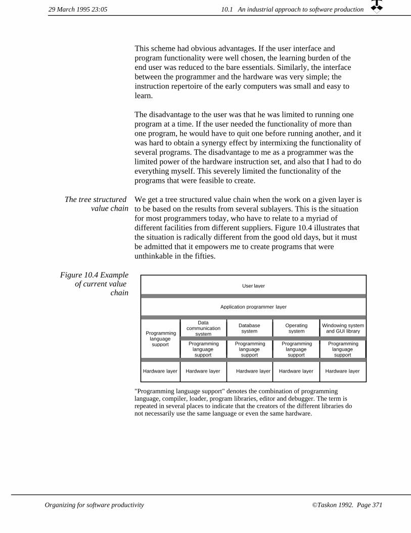
This scheme had obvious advantages. If the user interface and program functionality were well chosen, the learning burden of the end user was reduced to the bare essentials. Similarly, the interface between the programmer and the hardware was very simple; the instruction repertoire of the early computers was small and easy to learn.
The disadvantage to the user was that he was limited to running one program at a time. If the user needed the functionality of more than one program, he would have to quit one before running another, and itwas hard to obtain a synergy effect by intermixing the functionality ofseveral programs. The disadvantage to me as a programmer was the limited power of the hardware instruction set, and also that I had to doeverything myself. This severely limited the functionality of the programs that were feasible to create.
We get a tree structured value chain when the work on a given layer isto be based on the results from several sublayers. This is the situation for most programmers today, who have to relate to a myriad of different facilities from different suppliers. Figure 10.4 illustrates that the situation is radically different from the good old days, but it must be admitted that it empowers me to create programs that were unthinkable in the fifties.
The tree structured value chain
Figure 10.4 Exampleof current value
chainUser layer
Application programmer layer
Operatingsystem
Datacommunication
system
Databasesystem
Programminglanguagesupport
Programminglanguagesupport
Programminglanguagesupport
Windowing systemand GUI library
Programminglanguagesupport
Programminglanguagesupport
Hardware layer Hardware layerHardware layerHardware layerHardware layer
"Programming language support" denotes the combination of programming language, compiler, loader, program libraries, editor and debugger. The term is repeated in several places to indicate that the creators of the different libraries do not necessarily use the same language or even the same hardware.
10.1 An industrial approach to software production29 March 1995 23:05
©Taskon 1992. Page 371Organizing for software productivity

Real value chains in the real world will usually take the form of an acyclic, directed graph. We made figure 10.4 into a tree by cheating: some of the partitions in the hardware layer would almost certainly beshared among several partitions on the programming support layer. Our nice and simple model of figure 10.1 has now changed into the complex picture of figure 10.5, where the actors on one layer build onthe results from several suppliers on the layer below.
The directed graph value chain
Figure 10.5 A directed graph value
chain based on extensive reuse from
several sources
Level 4b
Level 3a Level 3cLevel 3b
Level 2bLevel 2a
Level 1a
As an engineer, I tend to think that a value chain should be the result of careful analysis and design rather than the result of an arbitrary happening. This is indeed the case for the initial value chain we created for Intelligent Network Services in cooperation with the Norwegian Telecom that we describe below.
Value chains createdby design?
For each class of systems, we could consider the complete value chainfrom the hardware through the end user facilities. The purpose is to process end user data, and we try to understand the kind of people who will be most effective on each layer. We then exploit all availabletechnologies to select the most effective for each layer.
Real life business is not as simple as this. Networks of organizations evolve under the influence of many pressures. Market pressures is the current fashion, but financial, political, technical and even moral pressures influence business evolution. The software business is no exception, and fragments of value chains are appearing spontaneously all around us: operating system vendors try to entice application programmers to build on their results; repository builders encourage providers of CASE (Computer Aided Software Engineering) tools to standardize on their products. Consultants and authors of newsletters try to make order out of chaos and influence vendors and users to use a common vocabulary and adapt to some common, high level architecture.
Value chains createdby natural selection?
29 March 1995 23:0510.1 An industrial approach to software production
©Taskon 1992. Page 372 Organizing for software productivity

Production engineerscreate the value
chain
When we first worked on the initial system for Intelligent Networks, we assumed that the people on one level would be totally responsible for the production facilities of the people on the layer above them. Butthen a member of the project asked the very pertinent question: But what is our role in this? We are not part of the chain, yet we design and implement it. This led to the idea of production engineering, which covers the design and implementation of value chains. This includes the chain architecture as well as choosing the appropriate technology for the different layers, specifying the work processes, choosing the production facilities, and installing them. This is illustrated in figure 10.6. We have now reverted to the simple, linear value chain model, because we believe it to be the duty of the production engineers to create the illusion of a linear chain even if they integrate systems and products from several vendors to implement a production facility.
No single enterprise controls all layers in the value chain. Most of us build on products delivered by our vendors, and many deliver products to customers in another enterprise. We can still think in terms of value chains, and organize our little part of it to the best of our ability. We can also influence our environment through user groups, industry associations, development consortia, etc.
End userLayer N
Layer N-1
Layer N-2
HardwareLayer 0
Productionengineering
Work processesand
production facilities
Figure 10.6 The role of the production
engineers
The focus on people and responsibility which is embedded in the idea of value chains has proven useful in a number of situations. We have found that very complex problems are greatly simplified when we addthe third, people dimension to the life cycle model. The examples described in the following sub-sections are but two examples.
Create your own value chain
10.1 An industrial approach to software production29 March 1995 23:05
Organizing for software productivity ©Taskon 1992. Page 373

There are two opposing forces. One which makes the producer tend towards specialization, another which makes the consumer want general suppliers:
1. People must specialize to be best in what they do, so they will tend to focus on a small part of the value chain.
2. Customers do not like to deal with lots of vendors, so they will prefer to buy everything from one company.
The solution could be that some vendors create specialized products, while other vendors specialize in production engineering and integratethese products to deliver complete production environments. Large programming shops can have their own production engineers and dealdirectly with the specialized product vendors.
If you believe that value chains can help you better organize your work, you may consider the following activities as part of your initial studies:
Identify all the people or organizational units involved, and describe the layers of the value chain. The top layer will be the ultimate end user of your software; that is the layer where value iscreated outside the realm of software. The bottom layer will likelybe some purveyor of hardware or basic software such as operatingsystems, communication systems and database services. Also include suppliers of computer aided software engineering tools. Make sure to include all layers, such as layers for distribution, installation, training and service.
1.
2. Describe the nature of the work performed in each layer and the success criteria of their actors.
Describe the kind of people who will be most effective on the different layers. You would expect to find extrovert people near the top of the chain because of their close relationship to the end users. The people near the bottom of the chain are likely to be introvert, more concerned about computational details than the happiness of users.
3.
Select suitable technology to support the work on each layer, specify the work processes and the production facilities. Be sure to be open minded when you select the technology, a simple duplication of master objects may be more appropriate than sophisticated technology such as automatic program generators.
4.
29 March 1995 23:0510.1 An industrial approach to software production
©Taskon 1992. Page 374 Organizing for software productivity

10.2 Large-Scale Production of Intelligent Network Services
In a nutshellThis section has been written for the interested layman, so we do not apologize to the telecommunications expert for glossing over the hard problems or for explainingprinciples that are well known to him.
The aim is to illustrate how different reuse technologies are appropriate on differentlayers of a practical value chains.
The telecommunications industry are expanding their product offerings with a number of new "Intelligent Network" (IN) services such as Universal Personal Telephone, which makes it possible to finda person wherever he is; Call Forward, which makes it possible to redirect incoming calls to alternative receivers; and many others. Our study was based on an elaborate life cycle model. We identified six different actors and mapped the activities of the life cycle model onto these actors to create a six-layer value chain. We found that the actors were very different in competence and outlook, selected appropriate technologies for each layer, and sketched out possible production facilities. We were pleased to discover that every one of the reuse technologies described in chapters 5 and 11 was applicable on at least one layer.
The result was a blueprint for a major industry. We believe its generalpattern shows the future of the software industry, and that a viable Intelligent Networks Industry could be based on our model. But studythe following pages and judge for yourself.
We report the results of the first iteration briefly in this chapter and more thoroughly in chapter 12. This iteration was performed in 1993 and reported with a paper and demonstration at the TINA conference of that year [Ree 93]. The next iteration takes place in 1994-95; its results were not ready in time to be included here.
A blueprint for an industry
A large number of different Intelligent Network services have been proposed, and some of them have already been made operational by some operators. We list a few to give you an idea of their nature:
Intelligent Networks (IN) provide
sophisticated telecommunications
services
1. Advice of Charge. The paying User is informed of usage-based charging information.
10.2 Large-Scale Production of Intelligent Network Services29 March 1995 23:05
Organizing for software productivity ©Taskon 1992. Page 375

Alternative Billing. A User can bill a call to a number other than the calling number.
2.
Automatic Call Distribution. Incoming calls are distributed to several operators according to a selectable algorithm.
3.
Call Forwarding. Incoming calls are redirected, either unconditionally or depending on load, time of day, etc.
4.
Conference Calling allows multiple users to participate in a singleconversation.
5.
6. Freephone (800 numbers). The call is free for the caller and paid by the called part.
7. Televoting. Call a number to cast your vote for your favorite hit tune or whatever.
Universal Personal Telecommunication. One telephone number will reach you wherever you are in the world.
8.
Video on Demand (VOD). Order your favorite movie to be screened, where you are and when you want it.
9.
Virtual Private Network. A private communication network with its own, independent numbering scheme. It is technically implemented in the public network, but logically separated from it.
10.
The construction and deployment of IN services is going to be a very large operation. There will be a large and expanding number of available services; the total system complexity will be staggering; and many organizations employing people in different capacities will be involved in its creation and operation.
IN will be one of the world's major
industries
A first separation of IN into two distinct domains has been suggested in [Vestli, Nilsen 92]; this is illustrated in figure 10.7. The Switching Domain encapsulates the network functions offered by the traditional telecommunications systems, and the Service Domain encapsulates allthe Intelligent Network service functionality. This is a client-server architecture, where the Service Domain is a client of the Switching Domain. The interfaces between client and server are defined in termsof high level operations, independently of the concrete switch design. Service Domain software is, therefore, portable in the sense that it canoperate against a range of different switches.
10.2 Large-Scale Production of Intelligent Network Services 29 March 1995 23:05
Organizing for software productivity©Taskon 1992. Page 376
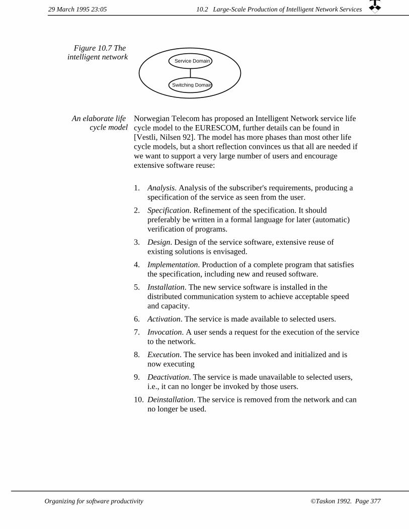
Service Domain
Switching Domain
Figure 10.7 The intelligent network
Norwegian Telecom has proposed an Intelligent Network service life cycle model to the EURESCOM, further details can be found in [Vestli, Nilsen 92]. The model has more phases than most other life cycle models, but a short reflection convinces us that all are needed if we want to support a very large number of users and encourage extensive software reuse:
An elaborate life cycle model
Analysis. Analysis of the subscriber's requirements, producing a specification of the service as seen from the user.
1.
Specification. Refinement of the specification. It should preferably be written in a formal language for later (automatic) verification of programs.
2.
Design. Design of the service software, extensive reuse of existing solutions is envisaged.
3.
Implementation. Production of a complete program that satisfies the specification, including new and reused software.
4.
5. Installation. The new service software is installed in the distributed communication system to achieve acceptable speed and capacity.
Activation. The service is made available to selected users.6.
Invocation. A user sends a request for the execution of the serviceto the network.
7.
Execution. The service has been invoked and initialized and is now executing
8.
Deactivation. The service is made unavailable to selected users, i.e., it can no longer be invoked by those users.
9.
Deinstallation. The service is removed from the network and can no longer be used.
10.
10.2 Large-Scale Production of Intelligent Network Services29 March 1995 23:05
©Taskon 1992. Page 377Organizing for software productivity

Many different individuals and enterprises will be involved in the creation and invocation of Intelligent Network Services. Typical examples are subscribers and end users, Public Telecommunications Administrations, "Teleshops", and independent software houses. These individuals and enterprises will, as a body, be responsible for supporting the complete Intelligent Network Service Life Cycle.
Many different actors
We analyzed the life cycle model and identified six actors who can be organized in a six-layer value chain as shown in figure 10.8.
Identify the value chain
User layer. The User is the party who wants to use available services, and who is responsible for selecting and invocating a service.
1.
Subscriber layer. The Subscriber is the party who purchases a set of services on behalf of one or more Users, who pays for them, and who is responsible for making the services available to his or her users.
2.
Service Provider layer. The Service Provider is a party who has a license for activating Intelligent Network service software for specified Subscribers. We think of the Service Provider as the corner Teleshop where consumers can buy regular services, but it could also be a professional customer consultant who sells specialized services to advanced corporations.
3.
Service Creator layer. The Service Creator is a party who has a license for defining Intelligent Network service software and install it in the telecommunications network. The Service Creator will currently be a Public Telephone Authority (PTA), but our model is open for several commercial Service Creator companies.
4.
5. Service Constituent Creator layer. The Service Constituent Creator is a party who has a license for producing software building blocks which may be configured into IN services. These software building blocks, called Service Constituents, are the reusable components used by the Service Creator to create servicesoftware.
Network Provider layer. The Network Provider is the party who provides the basic communications facilities used by the IN services.
6.
10.2 Large-Scale Production of Intelligent Network Services 29 March 1995 23:05
Organizing for software productivity©Taskon 1992. Page 378
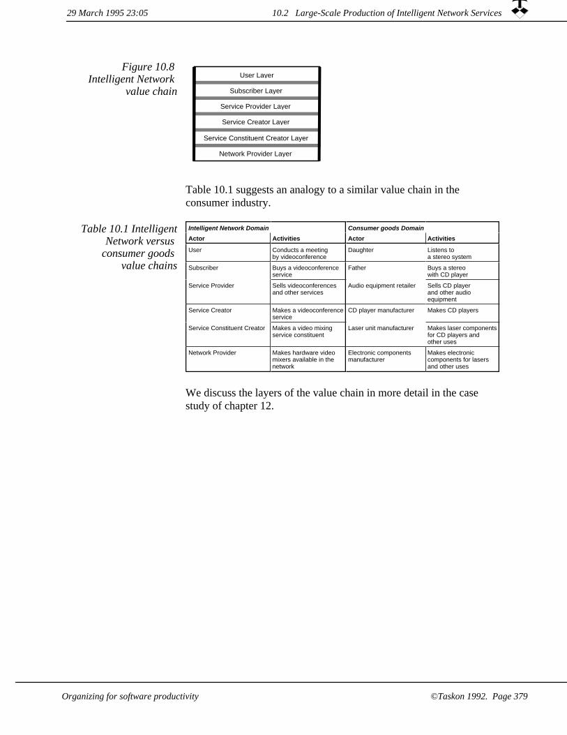
Service Provider Layer
Service Creator Layer
Subscriber Layer
Network Provider Layer
Service Constituent Creator Layer
User LayerFigure 10.8
Intelligent Network value chain
Table 10.1 suggests an analogy to a similar value chain in the consumer industry.
Table 10.1 IntelligentNetwork versus
consumer goods value chains
Intelligent Network Domain Consumer goods Domain
Actor Activities Actor Activities
User Conducts a meetingby videoconference
Daughter Listens toa stereo system
Subscriber Buys a videoconferenceservice
Father Buys a stereowith CD player
Service Provider Sells videoconferencesand other services
Audio equipment retailer Sells CD playerand other audioequipment
Service Creator Makes a videoconferenceservice
CD player manufacturer Makes CD players
Service Constituent Creator Makes a video mixingservice constituent
Laser unit manufacturer Makes laser componentsfor CD players andother uses
Network Provider Makes hardware videomixers available in thenetwork
Electronic componentsmanufacturer
Makes electroniccomponents for lasersand other uses
We discuss the layers of the value chain in more detail in the case study of chapter 12.
29 March 1995 23:05 10.2 Large-Scale Production of Intelligent Network Services
Organizing for software productivity ©Taskon 1992. Page 379

Large-Scale Production of Customized Business Information Systems
10.3
In a nutshellOne of the themes of this book is that object orientation enables us to create customized software which is adapted to the tasks and preferences of individuals. The tasks and preferences of professionals vary widely. Therefore, we need a great number of different tools and even greater number of configurations of tools into coherent information environments.
We cannot possibly hope to produce all the different information environments through traditional software development projects, and the use of shrink-wrapped software packages has its clear limitations. Therefore, we exploit object-oriented reuse technology to build a value chain for customized information environments for professionals. The main actors are the Tool-Makers, who configure the different information tools; the Module-Makers, who program configurable program components; and Kernel-Makers, who create the system architecture and common environment for the whole value chain.
We discussed the need for information environments for professionalsin chapter 7 in conjunction with the task/tool/service models. We will also see the need for such environments on all the layers in the value chain for Intelligent Network services. It was Douglas Engelbart who first saw the potential in using computers to augment the human intellect and support human cooperation. He pioneered the mouse and the multiwindow screen and a host of other ideas -- some of them are commonplace today and others will be commonplace tomorrow [Engelbart 62], [Engelbart 67], [Engelbart 92]
Information environments for
professionals
In the following, we will give a few examples to illustrate the personalaugmentation part of Engelbart's ideas: Business Information Systemsfor decision makers, experience based information environments, information environments for system designers. But it is important to realize that the essence of information environments are their uniqueness, since they should be tailored to the goals, needs and preferences of the professional user.
Business InformationSystems support
decisionmakers
Decisionmakers and other professionals need to harness both halves of their brains. They need logic and creativity; they need rational analysis of aspects that can be formalized and intuitive understanding of complex relationships beyond the reach of logic.
A Business Information System is a system designed to provide a decision maker with customized access to information sources for
29 March 1995 23:0510.3 Large-Scale Production of Cus...Business Information Systems
©Taskon 1992. Page 380 Organizing for software productivity

exploration and analysis. The creation of such a system starts with analyzing the user's tasks to see how improved access to information can help the decision maker be more effective.
We next search for information sources. We surprisingly often find that information which is essential to the decision makers cannot be derived from the information available in the enterprise computer systems. The essential information will then have to be provided by skilled personnel. We have in many cases had success with introducing the Information Editor as a new role in the organization, see figure 10.9. This is a highly competent and responsible person who collates information from many sources, evaluates and interprets it, and presents the digested results to senior decision makers through the common information system. The work done by the information editor is not new; it is done informally in most organizations. The official introduction of the information editor makes the work visible, respectable and repeatable.
Figure 10.9 Subdivision of the
User layer in a Business Information
System value chain
User layer
Basic informationprovider
Informationeditor
Seniordecision maker
I have met many managers of high technology enterprises who would like to capture and formalize the collective experience of the enterprise to make it less vulnerable to the vagrancies of its experts, and to ensure that the enterprise as a whole learns from experience and does not repeat past mistakes.
Experience based information
environments
Pipe maintenance intelligence
An example: A petroleum processing facility is composed of a very large number of pipes carrying a variety of fluids and gases ranging from the benign to the highly corrosive. The pipes have to be inspected at times to determine if they need to be replaced. Pipe inspection must be done during a planned process shut down, which iscostly and must be kept as short as possible. But a pipe failure can be dangerous to people and property and leads to a very costly catastrophic process shut down. There are clear benefits to be obtained if a systematic collection of pipe, inspection and failure data could be made directly available to the pipe manager for exploration.
10.3 Large-Scale Production of Cus...Business Information Systems29 March 1995 23:05
©Taskon 1992. Page 381Organizing for software productivity

A information environment for a pipe maintenance manager helps the manager plan the pipe inspection operations. To do this, he needs to collate a great deal of information, and he would also benefit from automated means to identify the most vulnerable pipe stretches amongthe many thousands he is responsible for. The tools have to be very flexible. The manager could, for example, suspect that pipes made from a certain batch of steel are causing trouble. Is this true, and if so,what are the afflicted pipes which may need immediate attention?
Is this experience formalization system a special Business InformationSystem? We tend to define a Business Information System as a system which primarily collects data from many sources, which presents accumulated views, which permits exception monitoring and automatic triggers, and which permits navigation in the information space. We regard the experience based information system as all of this, but, in addition, there is usually a significant element of specialized algorithms and possibly also decision support logic.
Distinction between information
environment categories blurred
An environment for systems developers
A system developer's information environment could consist of the following components. They should all be fully integrated in a seamless fashion:
Tools giving access to a model structure which is shared with other developers.
1.
Tools and repository for programming and debugging.2.
Facilities for reuse of patterns and frameworks.3.
An advanced documentation tool which supports a free mixture ofgeneral elements such as texts, drawings and tables together with special OOram report elements, and program source code.
4.
5. Facilities for software quality assurance.
An electronic mail system which supports general e-mail as well as transfer of specialized system data.
6.
A work process support system which help people cooperate without restraining their creativity, responsibility and initiative.
7.
29 March 1995 23:0510.3 Large-Scale Production of Cus...Business Information Systems
Organizing for software productivity©Taskon 1992. Page 382

All kinds of information
environments can be created
You would probably make a different list, and my list will probably be different a year from now. But this is immaterial for our argument: we start with goals, determine the kind of people who can best achieve them, and create a information environment which best supports these people in their preferred mode of working.
There is no value judgment in this; it is hard-nosed rationalism. Computers can be used to support the creative exploration of an information space as well as the repetitive (and mindless) entry of routine data. They can support free agents working voluntarily together towards a common goal, or command and strictly control people who work in a rule based environment. Or they can be used to support "distributed decisions with central control", where a responsible person may delegate the performance of a job to other people while retaining control of selected boundary conditions.
Figure 10.10 The value chain
System support layer
Kernel-Maker layer
Module-Maker layer
Tool-Maker layer
End User layer
Productionengineering
We have organized the creation of information environments for professionals into a five-layer value chain as illustrated in figure 10.10. The five layers of actors are as follows:
1. The End Users apply customized information environments to help perform their tasks. End users may also modify their information environment in various ways to adapt them to changing needs to the extent that this is part of its functionality.
We frequently find it profitable to apply the principle of value chains to the end users' organization. The End User layer is then subdivided; e.g., as illustrated in figure 10.9.
10.3 Large-Scale Production of Cus...Business Information Systems29 March 1995 23:05
©Taskon 1992. Page 383Organizing for software productivity

2. The Tool-Maker is a customer consultant whose task it is to empathize with end users, to provide their information environments, and to help them get maximum benefits from their tools.
A Tool-Maker reuses the Taskon library of information models and work processes, configures and specializes functionality created by a Module-Maker, generates user documentation, and makes the resulting systems available to the end users.
The Module-Maker is an application programmer who specifies, designs and implements new end user functionality.
The Module-Maker reuses the available library of patterns and frameworks to achieve maximum results with a minimum of effort. The Module-Maker also uses the company quality assurance standards and procedures to ensure that a new module conforms to its standards and guidelines.
3.
The Kernel-Maker is a systems programmer who creates the library of reusable patterns and frameworks, the standards, and the guidelines. The Kernel-Makers are also responsible for defining and maintaining the value chain with its associated procedures and tools; they are our production engineers.
4.
5. The Systems Software Suppliers are the vendors of operating systems, communication software, database management systems,compilers and runtime systems for the different hardware platforms employed by. They appear at the bottom of our value chain, but the vendors' value chains continue downwards.
Some of the systems software is less robust than we could desire and requires very specialized and detailed knowledge to make it run together with the rest of our software. This is one of the challenges that our production engineers have to face.
6. The Production Engineers are responsible for the methodologies for the upper four layers of the value chain.
Taskon's control of the bottom, System Support layer is limited. We may sometimes select product and vendor, but often have to accept selections made by the client. The Production Engineers package the selected basic software within our development environment and, if possible, protect the Module-Makers from its glitches and other peculiarities.
10.3 Large-Scale Production of Cus...Business Information Systems 29 March 1995 23:05
Organizing for software productivity©Taskon 1992. Page 384
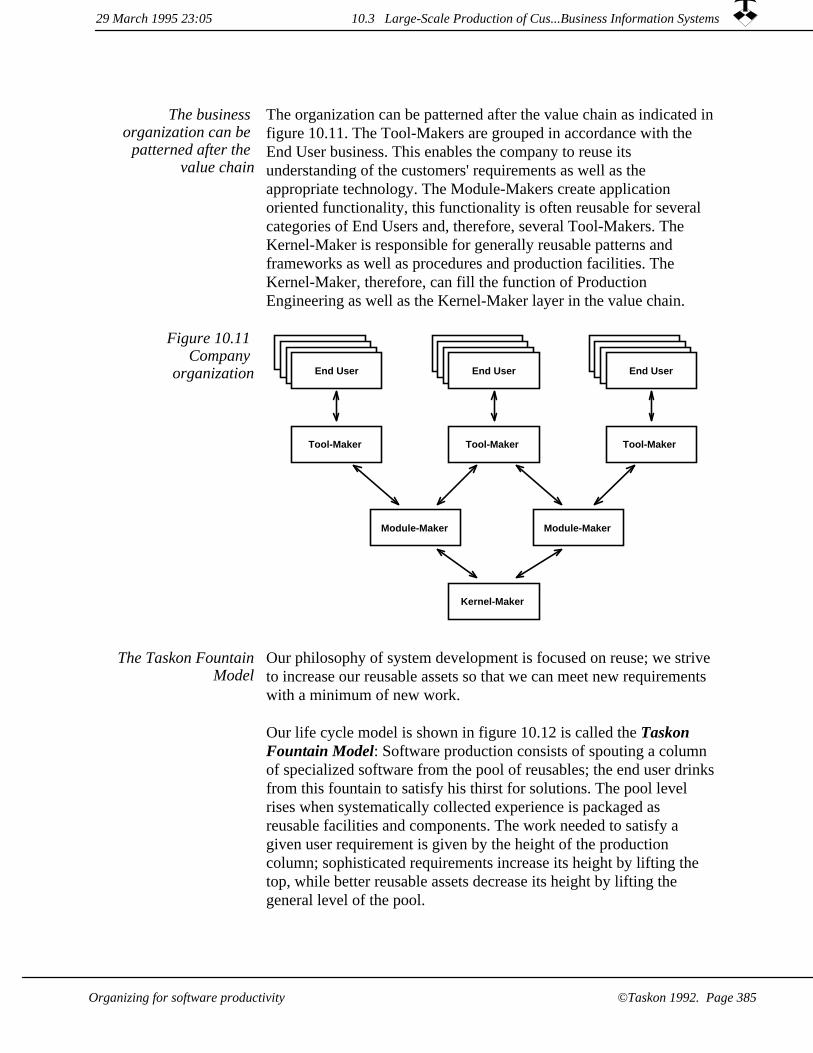
The organization can be patterned after the value chain as indicated infigure 10.11. The Tool-Makers are grouped in accordance with the End User business. This enables the company to reuse its understanding of the customers' requirements as well as the appropriate technology. The Module-Makers create application oriented functionality, this functionality is often reusable for several categories of End Users and, therefore, several Tool-Makers. The Kernel-Maker is responsible for generally reusable patterns and frameworks as well as procedures and production facilities. The Kernel-Maker, therefore, can fill the function of Production Engineering as well as the Kernel-Maker layer in the value chain.
The business organization can be
patterned after the value chain
Kernel-Maker
Tool-Maker
End UserEnd UserEnd User
Tool-Maker
Module-Maker
Tool-Maker
Module-Maker
Figure 10.11 Company
organization
Our philosophy of system development is focused on reuse; we strive to increase our reusable assets so that we can meet new requirements with a minimum of new work.
The Taskon FountainModel
Our life cycle model is shown in figure 10.12 is called the Taskon Fountain Model: Software production consists of spouting a column of specialized software from the pool of reusables; the end user drinksfrom this fountain to satisfy his thirst for solutions. The pool level rises when systematically collected experience is packaged as reusable facilities and components. The work needed to satisfy a given user requirement is given by the height of the production column; sophisticated requirements increase its height by lifting the top, while better reusable assets decrease its height by lifting the general level of the pool.
10.3 Large-Scale Production of Cus...Business Information Systems29 March 1995 23:05
©Taskon 1992. Page 385Organizing for software productivity

The life cycle model of figure 10.12 is orthogonal to the organization model of figure 10.11: the Tool-Makers, Module-Makers and Kernel-Makers all have their parts to play in both forward engineering and reverse engineering parts of the fountain model.
Figure 10.12 The Fountain Model for
Reuse
Fountainofproduction
END USER
Pool of reusable assets:* Production facilities (methodologies)* Reusable components: models, patterns, frameworks, objects
CollectionofExperience
Produce revenueIncrease complexity
Forward engineeringAdd functionality
Increase assetsDecrease complexity
Work analysisfor improvedprocesses
Reverse engineeringimproved* concepts* patterns* frameworks* configurable objects
10.3 Large-Scale Production of Cus...Business Information Systems 29 March 1995 23:05
©Taskon 1992. Page 386 Organizing for software productivity
System production activities aim at satisfying customer needs and generate revenue. The Tool-Makers are in the front line: they determine user needs, instantiate and structure library objects, and preset initial parameters and other configuration data.
If available functionality cannot satisfy the requirements, Module-Makers program new functionality by building on functionality available in the library. Since we aim at multiple sales to related markets, the special programs constitute a very small part of the delivered system, typically ranging from zero to one percent. The Module-Maker can focus on program functionality and robustness at the expense of generality and elegance, and he can frequently ignore questions of efficiency. Exploratory programming is ideal for this work, and is even used in the marketing phase to demonstrate the effectiveness of our technology.
The nature of the programming done in production activities leads to increased total system complexity; it is an entropy-increasing activity. If production is permitted to dominate for a period of time, there is a risk that the system will collapse under its own weight. The collapse will be clearly visible to everybody, because it manifests itself by a sharp and increasing rate of system bugs. Attempts at bug fixing can make the system worse, because the complexity makes it humanly impossible to fix one bug without introducing two new ones. The Module-Maker will, therefore, alternate between forward and reverse engineering: forward engineering when creating products, and reverseengineering when simplifying the programs and creating reusable components.
Production done by Tool-Makers and
Module-Makers
The collection of experience aims at increasing the value of our reusable assets and is an investment. The Module-Makers do reverse engineering on their ad hoc solutions, look for generalizations and powerful abstractions, and study feedback from users, and create improved application modules designed for reuse and specialization.
Kernel-Makers study all bug reports and gripes to identify trouble spots in our technology, do reverse engineering on the application modules in search for simplifications and common solutions, and create improved basic patterns and frameworks. They are also alert to stumbling stones in the production process and search for improved processes and tools.
The ultimate goal of the experience collection activities is to simplify
Experience collection done by
Module-Makers and Kernel-Makers
29 March 1995 23:05 10.3 Large-Scale Production of Cus...Business Information Systems
Organizing for software productivity ©Taskon 1992. Page 387

production and make it more efficient. The experience collecting activities lead to reduced system complexity, they are entropy-reducing activities. If the experience collecting activities are allowed to dominate, system functionality may become inadequate to satisfy market needs and the revenue stream may dry out. This is a sad situation even if the system is nice and clean and the programmers arehaving great fun.
Job rotation essential All our organization models in this chapter are considered as role models. The production engineers and the actors of the value chain layers are roles which must be mapped on to real persons. We believe there should be many-to-many relationships between roles and people.Specifically, we believe that people should alternate between production work and experience collection, between revenue creation and investment.
There is no limit to the dirty programs a keen production programmer may be willing to create to satisfy an urgent user requirement, but it helps if the same person from time to time cleans up other people's code and learns the hard way the kind of trouble caused by dirty code.
There is no limit to the time a keen experience collector can spend on finding an elegant solutions to a fictive problem, but it helps if the same person from time to time must produce end user functionality to strict time limits and learns what kinds of assets improve effectivenessand the total irrelevance of fancy solutions to non-existent problems.
We simply believe that all programmers benefit from taking their ownmedicine: be the end users of their own software, use their own reusables, clean up their own production.
You may well ask if this is applicable to large organizations with hundreds of programmers. We believe it is for two reasons. One is that it seems hard for a methodology section of a large programming organization to make front line programmers adopt their wonderful components, processes, and tools -- a certain interchange of people might help the transfer. The second is that the development of reusable assets by nature is a slow and painstaking process. A person who is working exclusively in that area will not understand the humble-tumble of front line programming, and will be hard put to create the optimum production facilities.
So if you consider the layers of the IN value chain in figure 10.8 or
Does it scale?
29 March 1995 23:0510.3 Large-Scale Production of Cus...Business Information Systems
©Taskon 1992. Page 388 Organizing for software productivity

the information environment value chain of figure 10.9, the best way to ensure that each value chain constitutes an organic whole is to let people play multiple roles. Not simultaneously, because the activities with the nearest deadline will then be given priority; but alternately sothat people get varied experience over time.
When I first entered the programming field in the late fifties, we tried to persuade a shipyard that it should invest in computer aided design. On one memorable occasion, the yard management had to decide if they were to spend their scarce investment resources on a new welding machine or on a computer for the new systems. Simple arithmetic showed that the welding machine would pay for itself in one year, while nobody knew if and when the computer would pay its way. Fortunately for us, management made a good decision and bought the computer.
The management of today has the same kind of problems when they allocate scarce resources. Should they enter into a contract with customer X which will generate a known cash flow and satisfactory profit, or should they invest the same resources in an improved, low level framework which is invisible to management and customers alike? It would be nice if we could apply a formula to compute return on a proposed investment in reusables. I am sorry to admit that we do not have a good solution, and that resource allocation to investment and production activities are based more on intuition than rational computations. But we do have some experience of schemes which do not work, at least not for us. We do have examples of reusable components which have never been used, and we have on one occasion been precariously near the brink of total system collapse. Wemake sure our collective experience, bad and good, is made known within the company so that we all can learn from it.
We believe that the creation of reusable components cannot be part ofproduction, because of the insurmountable clash between the goals and time schedules of the two kinds of activities. We believe that the creation of reusables cannot be an isolated operation, because it can then take off on a tangent. We believe that the creation of reusable components cannot be controlled by production (e.g., by production paying for them), because we lose the long term considerations that should dominate the investments.
Investment decisions are currently dominated by people who alternatebetween both types of activities, who understand the needs of production and the potential for improvement in the reusables. We are
Management challenge to hit right
balance between production and
investment
29 March 1995 23:05 10.3 Large-Scale Production of Cus...Business Information Systems
Organizing for software productivity ©Taskon 1992. Page 389

searching for work processes that will make the benefits of appropriate reusables more visible, and that will quantizise the cost ofdifficulties caused by inadequate methodologies and libraries.
We finish this chapter with the Taskon vision for software development: Study user requirements on a basis of experience from studying similar users; model user information by reusing models for similar users; specify tools which are adapted to the users' tasks; create systems without programming by duplication and conceptual modeling; if new functionality is required, create new software by marginally extending existing software. Reusable assets augment competent people to produce software which is cheaper, better adapted to user needs and more reliable than was achievable by using people alone.
Success depends on an ability to meet new challenges with existing components, producing high quality customized solutions in a short time and at a marginal cost.
Dedicated and creative people will still be of paramount importance tothe successful producer of software, but reusable assets will make them more effective.
The Taskon vision
10.3 Large-Scale Production of Cus...Business Information Systems 29 March 1995 23:05
©Taskon 1992. Page 390 Organizing for software productivity

Chapter 11Advanced reuse based on object instances
This chapter is written for the specially interested reader. The technology presented is independent of role modeling and constitutes an additional road to software reuse.
Introduction to object reuseRuntime configuration and object tradingOOram Composition System (OOCS).
The OOCS Schema Creator LayerThe OOCS Type Implementor Layer
Object duplicationshallowCopy -- too simple in most casespostCopy -- a default duplication algorithmstructureCopy for the general casedeepCopy - a dangerous operation
29 March 1995 23:05
©Taskon 1992. Page 391Advanced reuse based on object instances

11.1 Introduction to object reuse
In a nutshellWe have discussed how to reuse models and classes through inheritance and specialization. We shall now see how we can compose a system from a pool of predefined objects. This technology is entirely different from the OOram role modeling technology. It is not as mature, but it can become the most important reusetechnology of the future.
Encapsulation separates the external properties of an object from its internal implementation. Polymorphism permits different objects to use different methods for processing the same messages. The two properties taken together open an opportunity for constructing object structures by composition. A large variety of systems can be constructed from a limited set of objects by connecting them in different ways. This is an object-oriented variant of the system creation without programming that has proven so successful in the world of databases.
System creation by configuration
Many alternatives forselecting the class of
new objects
An object is created and inserted in the collaboration structure by some other object. The selection of the appropriate class for a new object may be accomplished in many different ways, ranging from thesimple and rigid to the complex and flexible. All of them have the common characteristic that they can be designed and implemented as general mechanisms that can be used by the application programmer according to simple rules.
As usual, there is no free lunch. Somebody has to decide on the kinds of structures to be supported, and somebody has to design the general interfaces that ensure that the different objects will fit together. It is hard to find the right balance between simplicity and power. The success of the Lego bricks demonstrates that the benefits can be substantial.
In the following sections, we present three different technologies for object reuse:
Runtime configuration and object trading. An object that needs a new collaborator asks a Trader service to instantiate a suitable candidate. The Trader holds a list of candidate objects. It managesa negotiation between requestor and candidates to select acceptable candidates. It chooses the appropriate one, instantiates it, and installs it as a collaborator to the requestor.
1.
29 March 1995 23:0511.1 Introduction to object reuse
Advanced reuse based on object instances©Taskon 1992. Page 392

OOram Composition System (OOCS). A conceptual schema is a description of the world as seen by the end user community. Conceptual schemas have been applied to database design with great success. The database conceptual schema controls the composition of data in the database, and so forms a bridge from the users' mental models to the concrete data representation. It also forms a bridge from data types to the users' mental models by specifying how the data are to be interpreted. We shall see thatwe can achieve similar results with objects.
2.
3. Object duplication. New objects can be created by instantiating a class, or they can be created by duplication of an existing object or object sub-structure. Both techniques are useful. Instantiation produces objects that are exactly as specified by the programmer. Duplication produces objects that reflect the history of the master object and is useful when we want to accumulate specific information in a master before duplicating it. Object duplication may appear to be a trivial operation, and in many cases this is true. The duplication of a general object structure is an operation full of pitfalls, however, and we will discuss the problem in depthbelow.
These object reuse technologies are described in the following subsections and illustrated in the case study of chapter 12: A Value Chain for Intelligent Network Services.
29 March 1995 23:05 11.1 Introduction to object reuse
Advanced reuse based on object instances ©Taskon 1992. Page 393

11.2 Runtime configuration and object trading
In a nutshellWe often want to create user interfaces where the user can navigate through an object structure and edit any chosen object. The challenge to the application programmer is to identify the type of the selected object, to select a suitable editor class, and to instantiate and install the selected class. This section gives you a general mechanism for creating a "dynamic matchmaker" which will achieve this goal and which you can use as the foundation when you want to create very powerful and user friendly user interfaces.
The position of the trading mechanism in our general model structure is indicated in figure 11.1.
Systemimplementation
Systemdesignmodel
Systemrequirements
model
Systemuser
model
Systemof objects
Trader libraryof editor classes
Legend:
Role Model Synthesis
Instantiation and linking
Editor class registration for trading
Figure 11.1 The Trader identifies
suitable editor class and instantiates it
Two objects may be linked as collaborators if each behaves properly towards the other. We could, for example, know an information objectand want to identify a suitable editor that can be linked to it. We frequently find we can use existing editors to edit new information objects. Similarly, a new editor class can often edit many existing information objects. The separation is particularly useful in the context of system configuration: a customer can buy and install a specific editor; it is then immediately available wherever it is applicable.
11.2 Runtime configuration and object trading 29 March 1995 23:05
©Taskon 1992. Page 394 Advanced reuse based on object instances
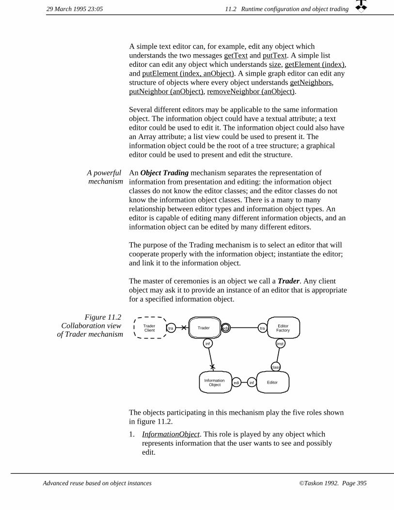
A simple text editor can, for example, edit any object which understands the two messages getText and putText. A simple list editor can edit any object which understands size, getElement (index),and putElement (index, anObject). A simple graph editor can edit any structure of objects where every object understands getNeighbors, putNeighbor (anObject), removeNeighbor (anObject).
Several different editors may be applicable to the same information object. The information object could have a textual attribute; a text editor could be used to edit it. The information object could also have an Array attribute; a list view could be used to present it. The information object could be the root of a tree structure; a graphical editor could be used to present and edit the structure.
An Object Trading mechanism separates the representation of information from presentation and editing: the information object classes do not know the editor classes; and the editor classes do not know the information object classes. There is a many to many relationship between editor types and information object types. An editor is capable of editing many different information objects, and aninformation object can be edited by many different editors.
The purpose of the Trading mechanism is to select an editor that will cooperate properly with the information object; instantiate the editor; and link it to the information object.
The master of ceremonies is an object we call a Trader. Any client object may ask it to provide an instance of an editor that is appropriatefor a specified information object.
A powerful mechanism
eds tratra
inst
class
edi inf
inf
Trader
InformationObject
TraderClient
EditorFactory
Editor
Figure 11.2 Collaboration view
of Trader mechanism
The objects participating in this mechanism play the five roles shown in figure 11.2.
1. InformationObject. This role is played by any object which represents information that the user wants to see and possibly edit.
29 March 1995 23:05 11.2 Runtime configuration and object trading
©Taskon 1992. Page 395Advanced reuse based on object instances

2. Editor. This object is responsible for the interface between a user and the designated information object.
3. TraderClient. This role is played by any object which knows an InformationObject and wants an editor for it.
4. Trader. This role is played by an object that is responsible for finding an editor for a given InformationObject. It is immutable, this means that it may not be specialized for different applications.
EditorFactory. This object is responsible for an editor class. It must be able to determine if an instance will be capable of editing a given InformationObject.
5.
There are two activities in the trading mechanism: Initialization and Trading. The Initialization activity must somehow instantiate the Trader object and load it with a list of EditorFactories. This list can besorted in priority sequence so that the first acceptable editor will also be the default one. We have hard coded a list of EditorFactories in ourcurrent implementation; it could alternatively be specified by the user or supplied through a configuration file.
Two activities
TraderClient Trader Editor
FactoryInformation
Object Editor
getEditorFor (anInformationObject)
supportedInterface
supportsInterface (interfaceName)
createInstance (anInformationObject)
setInformation (anInformationObject)C
Figure 11.3 Activity for selecting and instantiating and
editor
The Trading activity finds and instantiates an editor given an InformationObject. One possible sequence of events is illustrated in the scenario of figure 11.3:
getEditorFor. The TraderClient supplies the Trader with InformationObject and asks for a suitable editor
1.
supportedInterface/supportsInterface. The Trader traverses its EditorFactory-list in priority sequence. It first asks an EditorFactory for the name of its required interface. It then asks the given InformationObject if it supports this interface. If the answer is false, the Trader continues the search.
2.
11.2 Runtime configuration and object trading 29 March 1995 23:05
©Taskon 1992. Page 396 Advanced reuse based on object instances

createInstance. The first EditorFactory which answers true is asked to create an editor instance and to initialize it with the givenInformationObject as model.
3.
4. setInformation. The EditorFactory creates a new editor instance and initializes it with the specified InformationObject.
A variant of this activity lets the Trader collect the names of all technically acceptable editors and invite the user to indicate her preference before the editor is instantiated.
BOX: Selecting the editorIn our first Trader implementation, we presented a list of applicable editors to the user and invited her to select one of them. This proved exceedingly tedious, and we quickly created a second version of the Trader which automatically selected a default editor and instantiated it. This proved too inflexible, and our third and current version normally selects a default editor automatically, but there is an escapecommand which lets the user select any applicable editor.
This description of the Trading mechanism illustrates the separation of concern inherent in role modeling. The object that plays the Trader role in our system is a globally available object that plays a number ofother roles such as Transaction Manager, Persistent Store Manager, and Clipboard Manager. It would clearly be confusing if we were to describe all these roles simultaneously. We can also see that it is easy to discuss the Trading mechanism in the context of all the participating roles, and it is nice to know that we can map these roles on to actual objects in any way we please.
Objects typically play several roles
29 March 1995 23:05 11.2 Runtime configuration and object trading
©Taskon 1992. Page 397Advanced reuse based on object instances

11.3 OOram Composition System (OOCS).
In a nutshellAn OOram Composition System (OOCS) is a system that controls the creation of object structures by composition. The idea is that given a seed object, an OOCS Schema specifies the types of the objects that can be attached to it. One type is selected and instantiated, and the new object is attached to the seed. The composition proceeds by choosing new seed objects; selecting the type of a new addition; instantiating it; and attaching it to the growing structure.
Figure 11.4 illustrates that we use a special work process when we create a system by composition. The System User model describes the system environment as in the normal programming case. The System Requirements model has been modified into an OOCS schema. An OOCS schema is not only a description of the world as seen by the end user community, but it is also a precise and complete definition ofthe system. (It abides by the so called "100% rule".) In this sense the schema language is like a programming language. The difference is that the schema language builds on a few, simple notions which yield powerful leverage within its designated application area.
System creation by composition
Figure 11.4 Models on all levels may be
composed from simpler base models
OOCSSchema
Systemuser
model
OOCS Types
Systemof objects
BoxMy wife has been working as a database manager for a number of years. One of her reactions when helping me with this book has been that of frustration. Database technology has slowly been maturing so that she now can draw the conceptual
11.3 OOram Composition System (OOCS). 29 March 1995 23:05
©Taskon 1992. Page 398 Advanced reuse based on object instances

schema of a new application on a computer screen and push a button; the finished program is generated correctly and automatically. And it works immediately, every time! No detailed coding, no intricate bugs to track down. She felt that with object orientation, she would be back to the old days when she spent most of her time coding and debugging, working through the night to find the last bug before system installation, and more nights fighting fires to keep the system operational.
The first lesson to learn from this is that nobody should replace a mature technologywith a new one without good reason. The new technology may be more fashionable,but pressing requirements that cannot be satisfied by the current technology should be the only acceptable reason. Psychologists claim that we only ask for things that we believe to be feasible [Aronson 72], and we must be careful to read pressing requirements as real requirements, not perceived requirements.
The second lesson is that to any informatician, it is traumatic to move outside the boundaries of an established conceptual framework with its mature tool support. Butwe must admit that any conceptual framework has its limitations and that the pressures of real requirements sometimes force us to exceed them. There are basically two ways to achieve this. One is to add special programs outside the conceptual framework: we could, for example, write special user interface programswhich access the database without being part of it. Another is to extend the conceptual framework so that the desired functionality was within its new boundaries.
Database technologygives leverage
through restricted structure
A database system provides a framework for representing informationin the form of structured data. Its strengths and weaknesses are closely related to the way this is done. The first databases stored data in the form of trees; the relationships between data elements were all consist of -- part of relations. Later databases supported a general graph structure. They could be traversed along the relations, which could be of any kind. The current vogue is the relational database, where all data are organized in various tables.
A database system consists of the following parts:
A conceptual framework which defines the principles for database structuring. Examples: tree structure, graph structure, or tables. The conceptual framework also defines the types of the elements that can be stored in the structure. They are often collected in records that consist of a sequence of data items such as strings, numbers, dates, etc.
1.
Means for specifying and recording the database schema. The schema defines the structure of the database and its elements in user-related terms.
2.
Means for storing and managing data according to the rules and constraints specified in the schema.
3.
4. Means for retrieving data from the database. This includes findingthe required data and presenting them in a suitable form.
29 March 1995 23:05 11.3 OOram Composition System (OOCS).
Advanced reuse based on object instances ©Taskon 1992. Page 399

5. A program which manages the database at runtime.
Conceptual schemas are well known in the database community. Theydescribe the semantic relationships between data items arising from relationships in the "real world" of the problem domain. A conceptual schema can be used to specify a customized information system, and programming in the traditional sense can often be avoided altogether.
Relational databases offer a small, fixed
set of reusable data types
A conceptual schema specifies the system in terms of pre-defined datatypes; types such as String, Date, and Number are typically available. A Person could, for example, be defined as {Name (String), Address (String), BirthDate (Date), GrossIncome (Number)}. A Person is thus defined as a tuple of attributes; each attribute is specified by a name taken from the problem domain and a type selected from the predefined types. It is possible to specify more complex structures andimpose constraints on these structures. A Department can be specifiedas having Members and a Manager. Members and Managers shall both be Persons, and the structure may be constrained so that there is at most one Manager per Department, and so that the Manager must be a Member of the same Department.
The set of available data types is fixed and therefore considered as an integral part of the database system. We prefer to think of them as reusable programs; because we can then establish an analogy to an object system with an extensible set of available types. The database system builder created programs for these reusable types; and the application analyst uses them.
Extensible conceptual frameworks
Object technology seems very promising as a vehicle for extensible conceptual frameworks. We can add behavior to the static data of the conventional database. And we can replace the fixed domains of the database tables with object types, and thus get an extensible database system.
We should not get carried away by these possibilities. It is a sobering thought that the successful conceptual frameworks created over the past fifty years can be counted on one hand: the activity network, the database, and the spreadsheet come to mind. The successful introduction of a simple, powerful and widely applicable conceptual framework is clearly not a routine matter.
29 March 1995 23:0511.3 OOram Composition System (OOCS).
©Taskon 1992. Page 400 Advanced reuse based on object instances

Notice that we do not regard the object oriented database as a viable competitor to the relational database. The object-oriented database is too general; it can be used to represent anything and cannot be used without low-level programming. True competitors to the relational database will have to restrict their scope to enable effective, high-levelsystem specification and generation tools. The object-oriented database has to add a conceptual schema layer to compete with the relational database.
Object-oriented database not a
candidate
Conceptual foundation for the
object schema
The choice of conceptual framework is critical to the success or otherwise of a new composition system. Just as has been the case for database schemas, many different kinds of objects schemas are conceivable.
We have practical experience with one possible choice that we call the OOram Composition System (OOCS). The basic building blocks are objects that have the common characteristic that they can be linked together into different structures. These object structures are described generically in an OOCS Schema in terms of an extensible set of object types called OOCS Types. The "atom" of an OOCS Schema is the OOCS Entity, which associates a name taken from the problem domain with an existing OOCS Type.
The OOCS Schema controls the composition of the System of objectsin figure 11.4. The Schema is a kind of decision tree: Given an object,what are the types of the objects we may attach to it and what do the users call these parts? One of the possible types is selected, instantiated, and attached to the object structure.
This structure can, in principle, be any object structure. The general structure is realized as a tree with cross references. The tree is controlled by the OOCS Schema, the cross references are created algorithmically. For example, the Schema creator can specify that the cells of a table shall contain Texts or Pictures. The final binding of each cell to an appropriate column and row is done programatically.
OOCS Schema is decision tree
Let us consider a Document as an example of a problem domain, and let us model the Document as a structure of constituent parts as illustrated in figure 11.5.
11.3 OOram Composition System (OOCS).29 March 1995 23:05
©Taskon 1992. Page 401Advanced reuse based on object instances

Figure 11.5 Simplified OOCS
Schema for a Document
document , TreeNode
picture , PictureLeaf
caption , TextLeaf
figure , TreeNode
paragraph , TextNode
section , TreeNode
author , TextLeaf
title , TextLeaf
title page , TreeNode
table , TableNode
textCell , TextLeaf
pictureCell , PictureLeaf
OOCS Entities in bold, OOCS Types in italics. A document consists of a title page and sections; a title page consists of title and author, etc. This structure consists of 11 different entities. It is constructed from just four different object types: TreeNode, TextLeaf, PictureLeaf,and TableLeaf.
BOX: A dreamAll living tissues are built from a family of chemical compounds called proteins. A protein is a complex molecule which is composed of amino acids. There are just 32 different amino acids, and all forms of life are composed from these 32 building blocks. (This is the chemistry aspect, we ignore a host of other aspects.) Now consider that we were able to create 32 different objects which we could use to compose data systems as varied as life itself!
Figure 11.6 The OOCS value chain
Infrastructure creator layer
OOCS Type implementor layer
OOCS Schema creator layer
End user layer
The OOram Composition System gives rise to a value chain with four layers as shown in figure 11.6. (FOOTNOTE: Value chains were discussed in detail in chapter 10.)
The OOCS value chain
29 March 1995 23:0511.3 OOram Composition System (OOCS).
©Taskon 1992. Page 402 Advanced reuse based on object instances

End user layer. The end users create value when they add, retrieve, and remove objects in their OOCS system.
1.
2. OOCS Schema creator layer. The domain analyst who defines an OOCS Schema may work according to the suggestions given in chapter 7. The results will be expressed as OOCS Schemas rather than role models, and the implementation will be automatic, as suggested in figure 11.4. The technical aspects of creating OOCS Schemas will be discussed in section 11.3.1.
3. OOCS Type implementor layer. An important feature of the OOram Composition System is that it is truly extensible. Extensions come in the form of new OOCS Types; they are created by object-oriented programmers who base their work on the frameworks provided by the bottom layer. Section 11.3.2 describes the creation of OOCS Types in general terms.
Infrastructure creator layer. The infrastructure needed to support the OOram Composition System is quite sophisticated. It includesa module which exports a reusable framework to the OOCS Type implementor; safe editors for the OOCS Schema creator; a runtime system; and appropriate composition tools for the end users. The technical details of this module is a specialized topic which is outside the scope of this book.
4.
We will discuss the two middle layers in the following sub-sections.
The OOCS Schema Creator Layer11.3.1
Figure 11.5 shows an example structure that can be modeled with the OOram Composition System. We saw that the 11 different entities of a document could be realized by only four OOCS Types, and that alternative structures could be specified. But the notation used in the figure is inadequate for a complete OOCS Schema specification, because there is no way to specify constraints as to sequencing and cardinalities. We will now describe a solution that actually works in practice.
We start with an application pattern ("List of Instructions"), before describing the nature of the OOCS Schema in more detail ("Logical map").
11.3 OOram Composition System (OOCS).29 March 1995 23:05
Advanced reuse based on object instances ©Taskon 1992. Page 403

List of instructions: OOCS Schema Creation
It is appropriate to create an OOCS Schema if the world as perceived by the users can be modeled as a structure of available OOCS Type instances.
When to use
The Schema Creator is to specify rules for how the end user can compose object structures from predefined types. The rules shall be in the form of a decision tree: given an object in a partially completed structure, the rules shall specify all extensions permitted from it.
Problem
Solution An OOCS Schema is a generic specification of object structures. It associates the users' concepts with existing OOCS Types, and forms afoundation on which the end users can build and manipulate object structure instances.
You create an OOCS Schema by the following operations (not necessarily performed in this sequence):
1. Identify the users of the OOCS Schema: their goals, competence, working habits and preferences.
2. Identify the area of concern.
Analyze user environment and information requirements.3.
Model the information as a tree of OOCS Entities, giving them names that are meaningful to the users. Map each entity onto an OOCS Type.
4.
Inform the consumer community about the new system, motivate them to use it, train them, and make it available.
5.
References Necessary prerequisites are OOCS Types for all Entities; a schema editor that only permits the specification of legal structures; and the necessary runtime infrastructure including OOram trading for editor selection and instantiation.
29 March 1995 23:0511.3 OOram Composition System (OOCS).
Advanced reuse based on object instances©Taskon 1992. Page 404

The nature of OOCS Schemas
Objects are named, instantiated and interconnected according to a generic object structure or grammar specified in an OOCS Schema. The Schema is in many ways an object-oriented parallel to the conceptual schemas used to describe relational databases. Both are used to model interesting information, and both obey the "100% rule" which means that the schema contains sufficient information for the automatic generation of the application program. But there are three important differences:
The OOCS Schema
The relational model organizes information in a set of tables; the OOCS Schema organizes information in an object structure.
1.
The selection of available domains in the relational model is fixed; the set of available OOCS Types is extensible.
2.
The relational schema defines all legal data structures, and the database has to be restructured if the schema is changed. The OOCS Schema controls object structure editing by defining legal object insertions and deletions. The object structure survives Schema changes without restructuring.
3.
OOCSEntity
OOCSType
OOCSGroup
OOCSSchema
Figure 11.7 Semanticview of the OOCS
Schema notions
11.3 OOram Composition System (OOCS).29 March 1995 23:05
©Taskon 1992. Page 405Advanced reuse based on object instances

Figure 11.7 is a Semantic view of the OOCS Schema elements, and figure 11.8 shows an example OOCS Schema. The Schema elements are as follows:
1. The OOCS Entity represents all objects that occupy a corresponding position in an object structure. An OOCS Entity corresponds to a user concept and is given a user-defined name. Adocument object is at the root of figure 11.8. A document contains titlePage, paragraph, figure table and section. A figure contains caption and drawing.
2. The OOCS Type represents the type of the objects that may occupy the position of the associated Schema Entity. It is an abstract way of specifying the class of these objects. The TreeNode OOCS Type is mapped to a class and instantiated to represent document, titlePage, figure, table, or section. (A TreeNode is an object which can play the role of node in a tree structure and which does not have any special attributes.) The TextNode OOCS Type is mapped to a class and instantiated to represent title, author, paragraph, or caption. (The TextNode classcan be a subclass of the TreeNode class with a text attribute.)
The OOCS Group provides the sequencing mechanism for the Schema. The OOCS Entities defined under each Group can only be inserted behind the entities of the Groups in front of it, and in front of the Groups following it. In figure 11.8, all titlePage objects will be in front of all contents objects, which will be in front of all section objects. OOCS Entities defined under the sameOOCS Group can be inserted in any sequence. In our example, paragraphs, figures and tables may be inserted in any order. sections can only be inserted after all the contents.
3.
29 March 1995 23:0511.3 OOram Composition System (OOCS).
Advanced reuse based on object instances©Taskon 1992. Page 406

OOCS Entity is document
Recursivereference tocontentsGroup.
Recursivereference tosubSectionsGroup.
titlePage1:1
title1:1
author0:N
paragraph0:N
figure0:N
caption1:1
drawing1:1
caption1:1
tableBody1:1
table0:N
section0:N
document1:1
TreeNode
titlePage
subNodes ->contents ->subSectionssubNodes
contents subSections
TreeNode
TreeNode TreeNode
TableNodeTextNodeTextNode
subNodes
TreeNodeTextNode
TextNodeTextNode
OOCS Group is titlePage.All the titlePage entitiesmust come in front of thecontents and subSectionentities.
OOCS Type is TreeNode
DrawNode
cells
drawing0:N
text0:N
DrawNodeTextNode
drawElements
circle0:N
DrawCircle
line0:N
DrawLine
Figure 11.8 View of of OOCS SchemaThis example uses vertical presentation; horizontal presentation is also permissible. Recursive relations are shown as dashed lines.
Entity attributes OOCS Entities have a number of attributes which specialize the OOCS Type. An important attribute is the cardinality; it constrains thenumber of permitted instances and is displayed in the diagram as minimum count : maximum count. We must have exactly one titlePagewith exactly one title. We may have any number of author objects. author and title belong to the same Group, author objects can therefore precede and follow the single title object. Notice that the Schema controls editing operations and does not prescribe all permissible object structures. Modification of an Entity cardinality will therefore only influence permissible editing operations and not affect existing object structures.
29 March 1995 23:05 11.3 OOram Composition System (OOCS).
©Taskon 1992. Page 407Advanced reuse based on object instances

We have not shown other attributes here, but real systems will includeattributes for setting default object values, for giving hints about the printing of the objects, etc.
Entity, Type and Group specifications may be specified as a references to similar nodes somewhere else in the diagram; this permits the definition of recursive structures. In our example, the contents of a document may be any mixture of paragraph, figure, and table. The section group follows the contents group, and a section has a contents group followed by a new level of subSection group.
Recursive definitions permitted
The OOCS Type Implementor Layer11.3.2
An OOCS Type is a building block that the end user at his discretion may instantiate, attach to an object structure and edit. An OOCS Type instance is illustrated in figure 11.9. It is an object, or a cluster of objects, with one plug to attach to a socket in the existing object structure. It may also have one or more sockets for attaching additional OOCS Type instances. Most of the common OOCS Type functionality is captured in a framework so that the application programmer can focus on the application specific problems.
In a nutshell
OOCS Type
None, one or more socketsfor attaching additional
OOCS Types
One plugfor plugging into
existing object structure
Figure 11.9 The OOCS Type
The following problems have to be solved:The problems
1. Semantic correctness. The user shall be able to construct a semantically meaningful object structure by successively selecting and instantiating user-defined concepts and attach the instances to the object structure.
29 March 1995 23:0511.3 OOram Composition System (OOCS).
Advanced reuse based on object instances©Taskon 1992. Page 408

2. Syntactic correctness. The user shall only be allowed to attach objects that will cooperate properly; program failures caused by improper object structures cannot be tolerated.
Programming an OOCS Type. Each of the user-defined concepts must be associated with an existing class.
3.
Editor selection. The user shall be able to edit the attributes of theinstantiated OOCS Types.
4.
Semantic correctness
Two levels of semantic correctness
There are two levels of semantic correctness in the OOram Composition System architecture:
Human level semantic correctness is the responsibility of modeler. On the human level, the OOCS Schema should faithfully describe the notions of the user community. It is clearly the responsibility and raison d'etre of the OOCS Schema Creator to ensure that the model is correct in this sense.
1.
2. Technical level semantic correctness automatically enforced. On the technical level, semantic correctness means that the users' object structure should conform to the OOCS Schema. The OOram Composition System infrastructure implements a somewhat weaker constraint: it checks all insertions and removalsof OOCS Type instances against the OOCS Schema. This means that changing the OOCS Schema does not cause changes in existing information. For example, if we were to modify the OOCS Schema of figure 11.8 so that the cardinality of the author Entity was 1:1, old documents with none or multiple authors would still be valid. But the user would not be allowed to create anew document without an author, and he would not be permitted to remove the last author from an old document.
There are two reasons why we did it this way. One is that we do not know an algorithm that will intelligently transform an existing object structure to make it conform to the notions of a new OOCS Schema. Another is that we do not want to rewrite history. Users may change their mind about their object structures, but the old structures were created under the old assumptions and should be retained unchanged in the archives.
11.3 OOram Composition System (OOCS).29 March 1995 23:05
©Taskon 1992. Page 409Advanced reuse based on object instances

Our reasons may not be your reasons, and you may want a different solution. We believe that whatever the solution, the main responsibility for technical correctness should rest with the Infrastructure Creator because the implementation of model conformance is a hard problem which should be solved once and for all.
You may want a different solution
Syntactic correctness
There is a large subset of all object structures that will operate withouterror. Their objects will receive messages as needed, and messages sent to collaborators will be handled correctly. We say that these systems are syntactically correct; the word syntax here alludes to the composition of OOCS Type instances.
Syntactically correct programs do not
crash
The plugs and sockets of figure 11.9 are typed to ensure syntactic correctness. In our implementation, the OOCS Types are given uniquenames, and the OOCS Type implementor is fully responsible for ensuring that plugs and sockets with compatible names can be safely connected. Other schemes could be based on message signatures or mathematical descriptions of the interactions, but we elected to keep our scheme as simple as possible.
Our OOCS Types are organized in a type hierarchy so that a plug of a given type can be plugged into a socket with the same type or one of its subtypes. The OOCS Types of the document example in figure 11.8 are given in figure 11.10 (the hierarchy is indicated by indentation):
A name denotes an OOCS Type
Figure 11.10 Example OOCS Type
hierarchy
TreeObject| TreeNode| | DrawNode| TextLeaf| DrawElement| | DrawCircle| | DrawLine| TableNode
It is the responsibility of the OOCS Type implementor to specify the types of the component's plug and sockets as part of the programmingactivity described in the nest section.
11.3 OOram Composition System (OOCS). 29 March 1995 23:05
©Taskon 1992. Page 410 Advanced reuse based on object instances

Programming an OOCS Type
The OOCS Type Creator is responsible for the application-specific aspects of the component and must write the appropriate programs. The Infrastructure Creator provides a framework which the OOCS Type Creator must specialize to create a specific component. Common functionality is defined in the base classes of the framework, and the framework also describes a typical work process and relevant constraints.
The OOCS Schema assumes that all objects are organized within a tree structure. The role model is shown in figure 11.11. We see that the root object of a permissible structure must be able to play the Parent role, the leaf objects must be able to play the Child role, and allintermediate objects must be able to play both roles.
OOCS Schema defines tree structure
Figure 11.11 The Schema base model
dw
up
Parent
Child
The interfaces on the dw (down) and up ports define messages for traversing the structure; for maintaining the two-way links when inserting and removing nodes; for duplicating a subtree; etc.
OOCS Types derived All OOCS Types are derived from the Schema base model. The role model for a drawing application may, for example, be derived from the base model as illustrated in figure 11.12. The base model is first used to synthesize the up plug of the DrawNode, and then applied again to synthesize the the relation between the DrawNode and its DrawElements.
29 March 1995 23:05 11.3 OOram Composition System (OOCS).
©Taskon 1992. Page 411Advanced reuse based on object instances
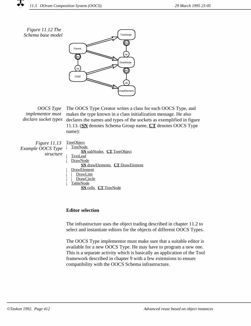
Figure 11.12 The Schema base model
dw
up
up
dw
dw
up
DrawNode
DrawElement
Parent
Child
TreeNode
OOCS Type implementor must
declare socket types
The OOCS Type Creator writes a class for each OOCS Type, and makes the type known in a class initialization message. He also declares the names and types of the sockets as exemplified in figure 11.13. (SN denotes Schema Group name, CT denotes OOCS Type name):
Figure 11.13 Example OOCS Type
structure
TreeObject| TreeNode
SN subNodes CT TreeObject| TextLeaf| DrawNode
SN drawElements CT DrawElement| DrawElement| | DrawLine| | DrawCircle| TableNode
SN cells CT TreeNode
Editor selection
The infrastructure uses the object trading described in chapter 11.2 to select and instantiate editors for the objects of different OOCS Types.
The OOCS Type implementor must make sure that a suitable editor is available for a new OOCS Type. He may have to program a new one. This is a separate activity which is basically an application of the Toolframework described in chapter 9 with a few extensions to ensure compatibility with the OOCS Schema infrastructure.
29 March 1995 23:0511.3 OOram Composition System (OOCS).
Advanced reuse based on object instances©Taskon 1992. Page 412
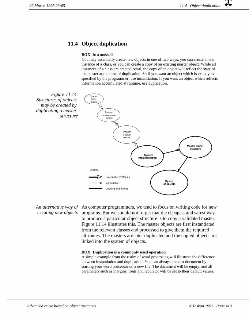
Object duplication11.4
BOX: In a nutshellYou may essentially create new objects in one of two ways: you can create a new instance of a class, or you can create a copy of an existing master object. While all instances of a class are created equal, the copy of an object will reflect the state of the master at the time of duplication. So if you want an object which is exactly as specified by the programmer, use instantiation. If you want an object which reflects information accumulated at runtime, use duplication.
Systemimplementation
Systemdesignmodel
Systemrequirements
model
Systemuser
model
Systemof objects
Master objectstructure
Legend:
Role model synthesis
Instantiation
Copying and linking
Figure 11.14 Structures of objects
may be created by duplicating a master
structure
As computer programmers, we tend to focus on writing code for new programs. But we should not forget that the cheapest and safest way to produce a particular object structure is to copy a validated master. Figure 11.14 illustrates this. The master objects are first instantiated from the relevant classes and processed to give them the required attributes. The masters are later duplicated and the copied objects are linked into the system of objects.
An alternative way ofcreating new objects
BOX: Duplication is a commonly used operationA simple example from the realm of word processing will illustrate the difference between instantiation and duplication. You can always create a document by starting your word processor on a new file. The document will be empty, and all parameters such as margins, fonts and tabulator will be set to their default values.
29 March 1995 23:05 11.4 Object duplication
©Taskon 1992. Page 413Advanced reuse based on object instances

Advanced authors often find it more effective to keep a library of master documentscontaining a letter, a telefax, a report, etc. Each master contains fixed contents parts such as headers and copyright notices, and may also contain keywords for the variable parts as reminders to the author. The author creates a new document by duplicating the appropriate master.
Less bureaucratically minded users, and I am one of them, just duplicate a recent document of the required kind and then delete all parts which are not needed.
A facility for the duplication of selected material is an important part of almost all user interfaces. Duplication is also a powerful technique for the production of software; the PC revolution would be unthinkable without program duplication, packaging and distribution. In the case study of chapter 12, we argue that the instantiation, processing, storing and duplication of master object structures will be an effective technique in the industrial production of customized software.
The problem
At a first glance, duplication seems as a simple and intuitively obviousoperation. In any given situation, it will be quite clear what should be copied and what should be left as it is. But this first glance is very misleading, because copy means different things under different circumstances -- the difference being in how we handle referenced objects.
Just consider the copying of an Array object containing pointers to a number of element objects. Do we want the copy to be another Array object pointing to the same elements, or do we also want to copy the elements? And how do we want to copy the elements?
The general problem is illustrated in the object structure of figure 11.15. Which objects should be copied together with the one in heavy outline? The answer clearly depends on the semantics of the object structure and the intentions of the user.
11.4 Object duplication 29 March 1995 23:05
©Taskon 1992. Page 414 Advanced reuse based on object instances
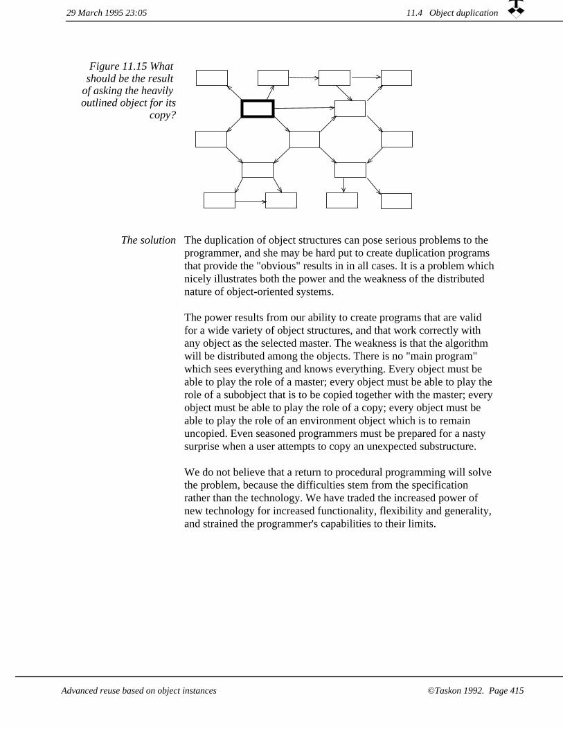
Figure 11.15 What should be the result
of asking the heavily outlined object for its
copy?
The duplication of object structures can pose serious problems to the programmer, and she may be hard put to create duplication programs that provide the "obvious" results in in all cases. It is a problem whichnicely illustrates both the power and the weakness of the distributed nature of object-oriented systems.
The power results from our ability to create programs that are valid for a wide variety of object structures, and that work correctly with any object as the selected master. The weakness is that the algorithm will be distributed among the objects. There is no "main program" which sees everything and knows everything. Every object must be able to play the role of a master; every object must be able to play the role of a subobject that is to be copied together with the master; every object must be able to play the role of a copy; every object must be able to play the role of an environment object which is to remain uncopied. Even seasoned programmers must be prepared for a nasty surprise when a user attempts to copy an unexpected substructure.
We do not believe that a return to procedural programming will solve the problem, because the difficulties stem from the specification rather than the technology. We have traded the increased power of new technology for increased functionality, flexibility and generality, and strained the programmer's capabilities to their limits.
The solution
29 March 1995 23:05 11.4 Object duplication
©Taskon 1992. Page 415Advanced reuse based on object instances

A framework candidate
No sane manager will ask a procedural programmer to create an algorithm that will copy an unspecified part of an unspecified structure. Even with object orientation, there is no magic. The only reason we can get away with such an open specification is that we canleave parts of the solution unspecified, to be filled in by the application classes where the nature of the objects is known.
We rephrase the problem as follows: Can we create a framework that protects the application programmer (and the users) against nasty surprises? The nasty surprises we have experienced all stem from unforeseen side effects. Our solution is that we let framework programs take care of the structural and interobject aspects of duplication, and leave the simple problem of duplicating individual objects to the application programmer.
Rephrasing the problem again, we want to create a framework for the duplication of objects and object structures that limits the task of the application programmer to override specific methods where she only need consider one class at the time. We have been through several cycles of solutions and nasty surprises; the surprises being caused by steadily more exotic problems. We will describe our current solution in subsection StructureCopy below, but we also discuss some simpler algorithms which are useful in many common cases:
shallowCopy, which just copies a single object.1.
postCopy, which is a way to let each duplicated object recursivelydetermine which of its instance variables should be copied.
2.
structureCopy, which is our general algorithm for duplicating partof a structure of interconnected objects.
3.
4. deepCopy, which recursively copies an object and all the objects referenced by its instance variables. This is a dangerous operation which we strongly advise you to avoid.
11.4.1 shallowCopy -- too simple in most cases
The simplest case is the shallowCopy. It creates a new object of the same class as the original which references exactly the same objects. This is illustrated in the figure 11.16.
11.4 Object duplication 29 March 1995 23:05
©Taskon 1992. Page 416 Advanced reuse based on object instances

cornerPoint
originPoint
aRectangleCopy
aRectangle
Figure 11.16 shallowCopy copies
the object and retains all references
unchanged
Heavy lines indicate the original structure; gray lines indicate the shallow copy.
shallowCopy of a Rectangle
shallowCopy may cause bugs which are hard to track down. In the past, we have experienced trouble with Rectangles which used to haveshallowCopy as its default copy operation. Rectangle objects have twoinstance variables as depicted in figure 11.16: origin, which is a Point object defining the upper left corner, and corner, which is a Point object defining the lower right corner. shallowCopy of a Rectangle master object yields a new Rectangle object which shares the origin and corner objects with the master. Do you see the possible problem?
Consider that you have a window with a number of views. The bounds of each viewwithin the window is stored as a Rectangle object. Open a new window as a copy ofthe first one. Rearrange the views of the copied window by modifying the x and y values of the origin and corner Points of their bounds, e.g., by the code bounds origin putXY (50, 25). The original window is also rearranged! Rearrange the viewsof the window copy by replacing the origin and corner Points with new Points, e.g., bounds putOrigin ((Point new) putXY (50, 25)). The original window is unchanged!
BOX: A mysterious side effect
11.4.2 postCopy -- a default duplication algorithm
A simple recursive algorithm
A new duplication algorithm was introduced in Objectworks\Smalltalk version 4.0. It is similar to the default algorithm we have been using internally at Taskon for many years, and works satisfactory in most cases. The idea is to create a shallowCopy of the original object, and then ask the copy to "do the right thing" with its own references.
The default copy method in class Object, the mother of all classes, is now as follows:
Object (copying)copy
^self shallowCopy postCopy
The method postCopy in class Object does nothing:
29 March 1995 23:05 11.4 Object duplication
©Taskon 1992. Page 417Advanced reuse based on object instances
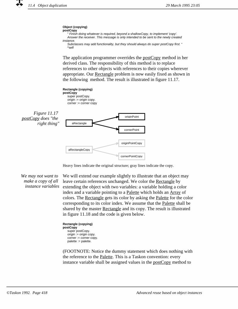
Object (copying)postCopy
" Finish doing whatever is required, beyond a shallowCopy, to implement 'copy'.Answer the receiver. This message is only intended to be sent to the newly created
instance.Subclasses may add functionality, but they should always do super postCopy first. "^self
The application programmer overrides the postCopy method in her derived class. The responsibility of this method is to replace references to other objects with references to their copies wherever appropriate. Our Rectangle problem is now easily fixed as shown in the following method. The result is illustrated in figure 11.17.
Rectangle (copying)postCopy
super postCopy.origin := origin copy.corner := corner copy
Figure 11.17 postCopy does "the
right thing"cornerPoint
originPoint
aRectangleCopy
aRectangle
cornerPointCopy
originPointCopy
Heavy lines indicate the original structure; gray lines indicate the copy.
We will extend our example slightly to illustrate that an object may leave certain references unchanged. We color the Rectangle by extending the object with two variables: a variable holding a color index and a variable pointing to a Palette which holds an Array of colors. The Rectangle gets its color by asking the Palette for the color corresponding to its color index. We assume that the Palette shall be shared by the master Rectangle and its copy. The result is illustrated in figure 11.18 and the code is given below.
We may not want to make a copy of all instance variables
Rectangle (copying)postCopy
super postCopy.origin := origin copy.corner := corner copy.palette := palette.
(FOOTNOTE: Notice the dummy statement which does nothing with the reference to the Palette. This is a Taskon convention: every instance variable shall be assigned values in the postCopy method to
11.4 Object duplication 29 March 1995 23:05
©Taskon 1992. Page 418 Advanced reuse based on object instances

show that the programmer has considered it. If a new instance variableis added to a class, our automatic quality checker will flag that its postCopy method is incomplete. (The same applies to some other methods such as initialize and release.))
Figure 11.18 postCopy does does
not copy a shared object cornerPoint
originPoint
aRectangleCopy
aRectangle
cornerPointCopy
originPointCopy
aPalette
Heavy lines indicate the original structure; gray lines indicate the shallow copy.
The postCopy algorithm works fine if each involved object knows what to do with all its instance variables, but it is insufficient if a wider context is required to determine the "right thing to do". We thenhave to use the structureCopy operation described in the next section.
11.4.3 structureCopy for the general case
This algorithm treats a directed graph roughly as a tree structure with cross-references. It assumes that we know how to start from a given root object and traverse the structure to find all objects that shall always be copied. It further assumes that with this knowledge available, we can identify the pointer variables that need to be modified. The algorithm is similar to postCopy, except that we now collect all copied objects before finalizing the operation.
Figure 11.19 shows an example. The subset of objects to copy depends on the selected root. We have selected object B, and want to copy D and E as well. We would have copied the whole structure if we had selected object A as the root, and only a single object if we had selected object D or E.
Copying a part of a directed graph
29 March 1995 23:05 11.4 Object duplication
©Taskon 1992. Page 419Advanced reuse based on object instances

F GED
CB
A
E*D*
B*
Figure 11.19 Structure duplication
example
The primary object to be copied is shown in heavy outline; the secondary objects which shall also be copied are shown in light outline; environment objects which shall not be copied are shown dashed. The duplicate objects and references are shown gray.
The algorithm has two phases:
Identify objects to be duplicated and create shallow copies. Traverse the master structure of objects. For each object, create a shallowCopy and save it in a dictionary that associates each master object with its copy. In figure 11.19, the dictionary associates objects B, D and E with the corresponding copies B*, D* and E*.
The framework takes care of structure traversal, object duplication and accumulation. The application programmer overrides the method objectsToBeCopied, which returns a Collection of instance variables that should always be copied if the receiver object is copied. For the example in figure 11.19, the method will return (D, E) in object B and empty collections in objects D and E. The cross-references are ignored in this phase.
1.
11.4 Object duplication 29 March 1995 23:05
Advanced reuse based on object instances©Taskon 1992. Page 420

Complete the copy operation in each object in the context of the set of duplicated objects. Each copied object is asked to fix its references given the dictionary of duplicated objects.
The application programmer must override the method completeDuplication which has one parameter: the dictionary of copied objects. This algorithm assumes that this will be sufficient information to determine what to do with the different references. There are three cases:
2.
Copied-to-copied. The reference is replaced with a reference to the corresponding copy. Example: after the shallowCopy, object D* will have a reference to object E. This reference is replaced with a reference to the corresponding copy found in the object dictionary, in this case E*. If this is a two-way pointer, we also inform the other object so that it can establish the reverse pointer. This is consistent with case 2, but implies that the method must tolerate that the reference has already been modified -- e.g., object D* will establish both reference D*-E* and E*-D*. When we get to D*, it has to recognize thisand do nothing.
¤
Copied-to-uncopied. The reference is left unchanged. Example: after shallowCopy, object E* will have a reference to object F, which is left unchanged. If this is a two-way pointer, it is the responsibility of object E* to inform object F so that it can establish the reverse pointer.
¤
Uncopied-to-copied. This is the case where an environment object shall have a pointer to the copy, but the copy does not know about it. In our example, object C shall establish a pointer to E*, but neither E nor E* knows C. This case is not covered by the general framework. The application programmer has to take special action, presumably in the completeDuplication method of object B.
¤
We could use this algorithm to duplicate the colored rectangle discussed in the previous subsection. The application programmer hasto write the two duplication methods in the ColoredRectangle class:
Revisiting the colored rectangle
ColoredRectangle (copying)addObjectsToBeCopiedTo: objectSet
super addObjectsToBeCopiedTo: objectSet.objectSet add: origin.objectSet add: corner.
ColoredRectangle (copying)completeDuplication: objectDictionary
super completeDuplication: objectDictionary.origin := objectDictionary at: origin ifAbsent: [origin].corner := objectDictionary at: corner ifAbsent: [corner].palette := objectDictionary at: palette ifAbsent: [palette].colorIndex := colorIndex.
29 March 1995 23:05 11.4 Object duplication
©Taskon 1992. Page 421Advanced reuse based on object instances

Two comments: Both methods call the corresponding method in the superclass (by super ...) to give it a chance to do its part of the algorithm. The completeDuplication method has a very general format: The reference is replaced with a reference to the copy if it is defined; it is otherwise left unchanged. More specialized code may beneeded if the semantics of the problem warrants it.
The application programmer need
not override the framework methods
The main methods for structure duplication can be defined in class Object and need not be modified by the application programmers. We include a sketch of these methods for your perusal.
Object (copying)structureCopy
" A client sends this message to obtain a structured copy of the receiver. "| objectDictionary |objectDictionary := IdentityDictionary new.self collectDuplicatesIn: objectDictionary.objectDictionary values do:
[:copiedObject | copiedObject completeDuplication: objectDictionary].
Object (copying)collectDuplicatesIn: objectDictionary
objectDictionary at: self put: self shallowCopy.objectSet := IdentitySet new.self addObjectsToBeCopiedTo: objectSet.objectSet do: [:subObject | subObject collectDuplicatesIn: objectDictionary].
Object (copying)addObjectsToBeCopiedTo: objectSet
^self
Object (copying)completeDuplication: objectDictionary
^self
11.4.4 deepCopy - a dangerous operation
An alternative is to use the deepCopy mechanism, which copies the object itself and all its collaborators recursively as illustrated in figure 11.20.
29 March 1995 23:0511.4 Object duplication
©Taskon 1992. Page 422 Advanced reuse based on object instances

C
copyE
E
D
B
Aoriginal
copyD
copyC
copyB
copyA
deepCopy
Figure 11.20 deepCopy copies the
object and all its references recursively
The recursive nature of deepCopy makes it unsuitable in many situations, and it can be quite devastating. Any circular object structure will lead to infinite recursion:
| arr | arr := Array new: 1.arr at: 1 put: arr.arr deepCopy.
Our recommendation is that you should never use deepCopy; use one of the other algorithms instead.
11.4 Object duplication29 March 1995 23:05
Advanced reuse based on object instances ©Taskon 1992. Page 423

29 March 1995 23:0511.4 Object duplication
Advanced reuse based on object instances©Taskon 1992. Page 424

Chapter 12Case study: A Value Chain for Intelligent
Network Services
This chapter is written for the specially interested person with a programming background. It illustrates the technical and organizational aspects of a specific value chain in some detail. We start by presenting an example target system, and describe its objects and execution processes. We then discuss each layer in turn.
A simple case with an extensible solutionUser layerSubscriber layerService Provider layerService Creator layerService Constituent Creator layerNetwork Provider layer
29 March 1995 23:05
Case study: A Value Chain for Intelligent Network Services ©Taskon 1992. Page 425

A simple case with an extensible solution12.1
In a nutshellProviding telecommunication services is a very large operation with many actors. This case study describes a possible value chain and fills in details for a plain telephone service. We populate each of the six layers in the value chain and choose appropriate technology for each layer.
Service Provider Layer
Service Creator Layer
Subscriber Layer
Network Provider Layer
Service Constituent Creator Layer
User LayerFigure 12.1
Intelligent Network value chain
Intelligent Network (IN) Services were introduced in chapter 10.2. We will now go into more detail. The value chain was shown in figure10.8, we repeat it in figure 12.1 for your convenience. The layers are as follows:
1. User layer. The User is the party who wants to use available services, and who is responsible for selecting and invocating a service. The typical User wants to concentrate on his or her tasks and should need to know a minimum of IN Service technology. Service interfaces should be as intuitive as possible, and only provide the functionality actually desired by each particular user.
The work processes on the User layer are determined by the user's tasks and are outside the scope of this discussion.
29 March 1995 23:0512.1 A simple case with an extensible solution
Case study: A Value Chain for Intelligent Network Services©Taskon 1992. Page 426

Subscriber layer. The Subscriber is the party who purchases a set of services on behalf of one or more Users, who pays for them, and who is responsible for making the services available to his or her users. In private households, the Subscriber is the User who enters into contract with the telecommunications provider and who pays the bills. In businesses, the Subscriber will often be a facilities manager. The personal profile of the Subscriber is similar to the User profile, but the professional Subscriber may require somewhat more sophisticated facilities. The success criterion of the Subscribers is that the Users get to create their value, effectively and effortlessly.
The work processes on the Subscriber layer are outside the scope of this discussion.
2.
Service Provider layer. The Service Provider is a party who has alicense for activating Intelligent Network service software for specified Subscribers. We think of the Service Provider as the corner Teleshop where consumers can buy regular services, but it could also be a professional customer consultant who sells specialized services to advanced corporations. The typical ServiceProvider person is a sales clerk or customer consultant with fairly short IN Service training, and should primarily be concerned withunderstanding customer needs and how they can be satisfied with available IN Service products. The success criterion is likely to bethat as many Users as possible use (and pay for) as many servicesas possible.
The main work processes on the Service Provider layer will be designed to support consulting and retail sales.
3.
4. Service Creator layer. The Service Creator is a party who has a license for defining Intelligent Network service software and install it in the telecommunications network. The Service Creator will currently be a Public Telephone Authority (PTA), but our model is open for several commercial Service Creator companies.The typical Service Creator person should understand the realitiesof the marketplace and the needs of the Service Provider, and cannot be expected to be expert in computer programming or the inner details of the IN technology. The success criterion is that the Service Provider constructs services that not only can be sold, but that actually will be used and create a revenue stream.
The main work processes on the Service Creator layer will involve collecting and analyzing market intelligence; specifying and defining products; and creating relevant documentation.
12.1 A simple case with an extensible solution29 March 1995 23:05
©Taskon 1992. Page 427Case study: A Value Chain for Intelligent Network Services

5. Service Constituent Creator layer. The Service Constituent Creator is a party who has a license for producing software building blocks that may be configured into IN services. These software building blocks, called Service Constituents, are the reusable components used by the Service Creator to create servicesoftware. The typical Service Constituent Creator person is a computer programmer specialized in some technical aspect of IN Services. The Service Constituent Creator will build on the resultsof the Network Providers and other Service Constituent Creators, and will understand how these results can be applied to the problems at hand. The success criterion will be that the Service Creators can create all the services that are needed in the market, and that the service constituents are simply presented to the Service Creators so that they can focus on the market and the products rather than the technology.
The main work processes on the Service Constituent Creator layerwill be crafted after some software life cycle model such as the waterfall model or the spiral model [Boehm 88].
Network Provider layer. The Network Provider is the party who provides the basic communication facilities used by the IN services. The Network provider must also have facilities to control the integrity of the network and its services. The typical Network Provider person will be expert in some aspect of communication switching technology. This is typically the responsibility of Public Telecommunications Authorities (PTAs). The Network Provider is, therefore, a large corporation possessing deep technical and commercial skills.
The main work processes on the Network Provider layer will be crafted to support the creation of very large, ultrareliable, distributed communication systems.
6.
The actors' knowledge of Intelligent Networking technology varies from nothing in the top layer to expert on the lower layers. Their interest in the subject varies correspondingly from the User, whose interests definitely lie somewhere else, to the Network Provider, whose professional life is centered on telecommunications technology. This must be reflected in the kind of facilities to be installed on the different layers, and hence also the underlying technology.
Matching requirements to
technology
29 March 1995 23:0512.1 A simple case with an extensible solution
Case study: A Value Chain for Intelligent Network Services©Taskon 1992. Page 428

No programming in four upper layers
Seen from a User, a service appears as something concrete which maybe bought and used. Seen from the IN system, a service is rather intangible; it is realized as a number of interacting objects. Some of these objects are specific to the service, while others are shared with other services.
The specification of a computation such as the execution of an IN service is traditionally considered as an exercise in computer programming. But computer programming is notoriously expensive, time consuming and error prone. This makes us take a much broader view, and we are actively searching for ways of specifying IN services that avoid programming. Possible means to achieve this without loss of flexibility is through parameterization of general objects, duplication of library objects and object structures, and instantiation controlled by conceptual schemas. When we do have to create new programs, the effort can be materially reduced by the proper application of frameworks and other reusable components.
BOX: What is programming?Programming could be defined as the specification of a computation. System generation through parameterization; table driven system generation; simple, application-specific visual generating tools, etc., would then all be classified as programming. We use "programming" in a more restricted sense, and limit it to mean the specification of a program in a programming language such as Eiffel, C++, or Smalltalk.
It was interesting and instructive to discover that all our reuse technologies found their proper place in the IN Service value chain. The highlights can be summarized as follows:
All reuse technologies needed
for IN Services
User layer and Subscriber layer. If the service is appropriately designed, the two top layers may customize it by duplication and supplying suitable parameters.
1.
Service Provider layer. The Service Provider specifies specific services for a customer in the form of a contract document. The document is edited on a syntax-directed editor controlled by an OOCS Schema.
2.
Service Creator layer. The Service Creator specifies the Universeof all possible services and combinations of services that may be sold by the Service Provider. The specification is in the form of an OOCS Schema. The Service Provider defines the service entities and binds them to appropriate OOCS Types. (Called Service Constituents in the IN community).
3.
29 March 1995 23:05 12.1 A simple case with an extensible solution
Case study: A Value Chain for Intelligent Network Services ©Taskon 1992. Page 429
Service Constituent Creator layer and Network Provider layer. The Service Constituent Creation and the Network Provider layers are the only layers involving programming in the traditional sense. This programming is minimized through the application of frameworks. The deliverables are OOCS Types.
4.
We illustrate the nature of the IN value chain through a system that was demonstrated at TINA-93 [Ree 93]. The system was designed so that its operation could be demonstrated on a computer screen. The running system consisted of 18 objects -- ridiculously simple in terms of telecommunications technology, but sufficient to illustrate how we match actors and technology in the IN value chain.
An initial system
We describe the operation of the running system in this section, and use it as a background for our subsequent discussion of the different layers in the succeeding sections.
The service in our initial system is what is affectionately known as POTS -- Plain Old Telephone Service. Person-A wants to establish a telephone conversation connection to Person-B. It is the responsibilityof the service to establish the connection between the parties. The service is dormant while A and B converse. The service is again activated to take down the connection and arrange for charging when the conversation is complete. Our system focus on the first phase: establishing the connection.
The Plain Old Telephone service
Our implementation separates POTS into two parts: an A service which is responsible for the calling end, and a B service which is responsible for the called end. This makes it possible to let the called party decide what to do with an incoming call: reject it, accept it, or direct it to specified equipment or to another User. We have implemented the following two service objects:
1. a Calling Telephone Service (Tel-A), which tries to establish a connection to User-B. The Users are identified by their userIDs inthe Service Domain, and the Telephones are identified by their accessPointIDs in the Switching Domain.
a Called Telephone Service (Tel-B) with the capability to accept or refuse the incoming request, to forward the call to a third User, or to route the call to one of a number of Telephones associated with User-B. In the latter case, User-B may be thought of as a manager of several operators, for example, in a booking office. Each operator is characterized by a Telephone with its own accessPointID, and Tel-B selects one of them to handle each incoming call.
2.
12.1 A simple case with an extensible solution 29 March 1995 23:05
©Taskon 1992. Page 430 Case study: A Value Chain for Intelligent Network Services

A single object called InvocationManager, #102 InvMngr, is the mainpoint of contact with the Service Domain for all Users. This object delegates the management of each User's affairs to an Invocation Analyzer object associated with each User (#104 Anlz-A and #106 Anlz-B). Specifically, an Invocation Analyzer object holds a set of master service objects that represent all services available to its User.
Invocation Manager and Invocation
Analyzer are the main objects in the
Service Domain
The public switched telecommunication network is an enormous distributed computer system; by direct dialing I can choose to connectto any one of some 200 million different B-Users. Many different operators operate equipment of many different kinds, but it is all interconnected into the one, coherent global communication system.
A virtual model of the switch for IN
The IN architecture (FOOTNOTE: See figure 10.7 on page 378??) encapsulates this distributed and nonhomogeneous system and presentit to the Service Domain as a coherent service, accessible through common, high level interfaces.
The Network Connection Point
One example of such an interface is a Network Connection, which enables an IN service object to order the interconnection of two or more access points in the Switching Domain. A Network Connection has one Connection Point and any number of Legs, see figure 12.2. Several telephones can be interconnected through Legs which share a common Connection Point. A Leg is an abstract wire with two termination points: the Connection Point and the socket in the wall which is identified by the accessPointID and where you plug in your telephone.
Networkaccess point
withaccessPointID
Networkaccess point
withaccessPointID
Leg
Leg
ConnectionPoint
Figure 12.2 A Network Connection
interconnects any number of network
access points by Legswhich meet in a
common Connection Point
The initial object structure is shown in figure 12.3. The Users are represented by two User objects, #103 User-A and #105 User-B. #103User-A is responsible for requesting a service (Tel-A) and initiating the invocation process, presumably through some user interface program inside the object. The #105 User-B object is responsible for accepting or refusing the requested call, as specified in the Calling Telephone service.
18 objects in the initial system
12.1 A simple case with an extensible solution29 March 1995 23:05
©Taskon 1992. Page 431Case study: A Value Chain for Intelligent Network Services

#107Tel-A
#108Tel-B
#104Anlz-A
#103User-A
#107-1Tel-A
#102InvMngr
#111Tel-B
#106Anlz-B
#117AP-Sel
#118CallForw
#111-1Tel-B
#105User-B
#117-1AP-Sel
#118-1CallForw
#113SwMngr
#114ConPt
#115Leg-A
#116Leg-B
Data for User A (Carl Petter)with Service library A
Data for User B (Trygve) with Service library B
Switching Domain
Figure 12.3 Service Domain objects
involved in establishing a
Telephone Service
A typical invocation process is as follows:
1. The User object represents the User, think of it as an object whichresides within the User's telephone. #103 User-A desires to establish a telephone service to User-B. It starts by asking the invocation manager #102 InvMngr for access to A's invocation analyzer. InvMngr returns a pointer to #104 Anlz-A.
#103 User-A then asks #104 Anlz-A for a Calling Telephone Service. #104 Anlz-A checks its store of service objects, selects #107 Tel-A, installs a duplicate #107-1 Tel-A as the current activeservice object, and returns a pointer to this copy.
2.
#103 User-A asks #107-1 Tel-A for a call to a user identified by its userID.
3.
#107-1 Tel-A asks #102 InvMngr for access to the invocation analyzer of the user with the given userID, and gets a pointer to #106 Anlz-B.
4.
12.1 A simple case with an extensible solution 29 March 1995 23:05
©Taskon 1992. Page 432 Case study: A Value Chain for Intelligent Network Services

#107-1 Tel-A asks #106 Anlz-B for its Called Telephone Service. #106 Anlz-B checks its store of service objects, selects #111 Tel-B, installs a duplicate #111-1 Tel-B as the service object currentlyactive for B, and returns a pointer to this copy.
Notice that the choice of calling service was done in an object belonging to A, while the choice of called service was done in an object owned by B. This permits detailed customization to the preferences of different Users.
5.
#107-1 Tel-A asks #111-1 Tel-B if it will accept a call. We assume the answer is YES.
6.
7. #107-1 Tel-A asks the globally available manager of the Switching Domain, #113 SwMngr, for a Connection Point. The manager creates one and returns a pointer to #114 ConnPoint.
#107-1 Tel-A asks #114 ConPt for a Leg. #114 ConPt creates oneand returns a pointer to #115 Leg-A.
8.
#107-1 Tel-A sets the accessPointID of User A in #115-Leg-A.9.
#107-1 Tel-A requests #111-1 Tel-B to establish a leg from #114 ConnPoint to the accessPointID of whichever Telephone it wants to take the call.
10.
11. #111-1 Tel-B is now free to select the called Telephone in any way it chooses. In our initial implementation, #111-1 Tel-B may be initialized with any number of selectors, each selector containing a condition and an action. The condition can be on time of day, day of week, holiday/workday etc. Two kinds of selectors provide two different kinds of actions: either selecting an Access point belonging to User-B, or forwarding the connection request to some other User. In figure 12.3, only one selector of each kind is shown (#117 AP-Sel and #118 CallForw).The selectors are tested sequentially; the first with a satisfied condition will be activated. If none of the selectors are satisfied, adefault Telephone will be used.
If the call is to be completed by #111-1 Tel-B, #111-1 Tel-B uses its selected accessPointID and the Connection Point reference to establish a Leg to the Connection Point.
12.
13. The network connection in the Switching Domain is established, and the conversation can commence.
12.1 A simple case with an extensible solution29 March 1995 23:05
©Taskon 1992. Page 433Case study: A Value Chain for Intelligent Network Services
12.2 User layer
In a nutshellThe User is the party who wants to use available services, and who is responsible forthe selection and invocation of a service. The invocation leads to the creation and installation of a copy of the relevant objects and the execution of the service. All remaining parameters must be bound by the User as part of the service invocation.
The cryptic codes to be used to activate current telephone services are printed on one of the first pages in the telephone directory. A few examples translated from our local telephone directory:
Current interfaces cumbersome
Call Forward Unconditionally (CFU): wait for dialing tone, touch*21*, touch new number which is to receive call, terminate with #, wait for acknowledge tone, hang up. To cancel CFU: wait for dialing tone, dial #21#, wait for acknowledge tone, hang up.
1.
Call Forward on Busy (CFB): wait for dialing tone, touch *67*, touch new number which is to receive call, terminate with #, wait for acknowledge tone, hang up. To cancel CFB: wait for dialing tone, dial #67#, wait for acknowledge tone, hang up.
2.
Call Forward on no Reply (CFR): wait for dialing tone, touch *61*, touch new number which is to receive call, terminate with #, wait for acknowledge tone, hang up. To cancel CFR: wait for dialing tone, dial #61#, wait for acknowledge tone, hang up.
3.
We would like to assume a simpler user interface: some of the users' telephones could have a switch with an associated warning light. A user leaving the office will throw the switch; this causes the warning light to come on and a CFU to a predefined number. When entering the office again, the user will return the switch to the off position, canceling the service and extinguishing the light. More advanced telephones could have a touch sensitive screen that supported simple, yet powerful interaction with the user.
Invocation by tradingand object duplication
In our initial system, an Invocation Analyzer object was allocated to each user. All services available to the User were stored in a library ofmaster objects in the User's Invocation Analyzer object (encapsulated aggregation). The Invocation Analyzer was partially responsible for the following steps in the life cycle model:
29 March 1995 23:0512.2 User layer
Case study: A Value Chain for Intelligent Network Services©Taskon 1992. Page 434

1. Activation. The service is made available to the User by adding a service object to the set of services which is managed by the Invocation Analyzer object.
Invocation. The User's Invocation Analyzer object selects a suitable master service object in response to a request from the user (via some terminal equipment) or from a service object, duplicates it and installs the copy for execution. Remaining open parameters, such as the new number which is to receive a forwarded call, must be bound before execution.
Object trading technology described in chapter 11.2 was used to assure that the selected service object was appropriate for the requesting client; object duplication was done according to the algorithms described in chapter 11.4.
2.
3. Execution. The selected service objects were responsible for service execution, but they were monitored by the Invocation Analyzer which handled exceptions and service termination.
Deactivation. The Invocation Analyzer removes the service from its library of master service objects.
4.
User production facilities
The User's production facility is defined by the Subscriber. It consistsof an (advanced) telephone which is permanently associated with the Invocation Analyzer object. The Invocation Analyzer object is loaded with objects for all services available to the user.
29 March 1995 23:05 12.2 User layer
©Taskon 1992. Page 435Case study: A Value Chain for Intelligent Network Services

Subscriber layer12.3
In a nutshellThe Subscriber is the party who purchases a set of services on behalf of one or moreusers, and is responsible for making the services available to them. The work of the Subscriber involves selecting a desired service and making a copy of the relevant objects available to the User. Some of the service parameters may be bound as part of this process.
We assume that the Subscriber has a special terminal with bitmapped display, keyboard and a pointing device. The Subscriber could, for example, manage service availability to the individual users through a direct manipulation interface as shown in figure 12.4.
Possible user interface
Subscriber Service
CFB
CFU
Switched CFU
CFR
Customize
Figure 12.4 A possible Subscriber
tool
This interface has one column for each User and one row for each available Service.A cross in a cell indicates that the given Service is not available for the given user, presumably because the User's equipment does not support it. Other cells are touch sensitive, clicking in the cell causes the corresponding Service to be activated (checked) or passivated (blank) for the given User. There is a Customize button for each service which may be customized through this interface. If the Subscriber wants to customize a service, he clicks the Customize button which causes a new interface to pop up. In this case, this interface will probably allow the Subscriber to set the target for the Switched CFU.
The Subscriber is partly responsible for the Activation and Deactivation steps in the life cycle model. The subscriber is represented by an object in the IN system which holds an object for each of the services purchased by the Subscriber. Applying the interface shown in figure 12.4, the Subscriber makes these services available to individual Users.
Subscriber responsible for
Service Activation and Deactivation
29 March 1995 23:0512.3 Subscriber layer
©Taskon 1992. Page 436 Case study: A Value Chain for Intelligent Network Services

1. Activation. The service is made available to the Subscriber by adding a master service object to the set of service objects which is managed by the Subscriber's management object. Some serviceparameters may be bound at this stage.
The service are later made available to the Users by duplicating the service masters, binding parameters, and installing the copies as new masters in the Users' Service Analyzer objects.
2. Deactivation. A service is made unavailable by removing the corresponding service objects from the Subscriber manager objectand the Invocation Analyzer objects of all the Subscriber's Users.
Subscribers were omitted from our initial system to keep it as simple as possible. You will, therefore, not find any Subscriber objects in figure 12.3.
The Subscriber's production facilities
The Subscriber production facility consists of some suitable equipment which supports the Subscriber's tool, e.g., the one shown in figure 12.4.
29 March 1995 23:05 12.3 Subscriber layer
Case study: A Value Chain for Intelligent Network Services ©Taskon 1992. Page 437

12.4 Service Provider layer
In a nutshellThe Service Provider is an actor who is licensed to customize services and make them available to Subscribers. The Service Provider selects services and service variants, and commands the instantiation of the necessary objects and their installation in the Subscriber's management object. (Directly into the User's invocation analyzer object in our initial system, which does not have a Subscriber layer.)
The main responsibility of the Service Provider layer is to define Subscribers and their services. An appropriate medium for this information is a Service Contract Document, which may be printed (and signed), and which may be executed to cause the installation of the Subscribers and their services in the Service Domain.
Possible user interface
The initial tool for creating this document is the intelligent editor shown in figure 12.5. It permits the Service Provider to create any andall permissible service variants, but which automatically prevents the creation of illegal combinations.
Figure 12.5 Editor for specifying the Service Contract
Document
29 March 1995 23:0512.4 Service Provider layer
Case study: A Value Chain for Intelligent Network Services©Taskon 1992. Page 438

The tool in figure 12.5 is in two parts: The left margin gives a graphical representation of the structure. The rectangular symbols are OOCS Entities, they represent the kind of object shown to the right. The small, black triangles represent insertion points, they indicate where the user can insert additional objects. An insertion point only permits the insertion of new objects which are appropriate at that point in the structure as specified in the OOCS schema. (FOOTNOTE: See the following section.)
The tool edits a tree structured model
The tool supports lowlevel concepts such as texts, graphics and tables,as well as highlevel concepts such as IN Services and Access Point Selectors. A trading mechanism activates an appropriate editor when the user points inside one of the information objects in the right part of the tool. The tool permits selective zooming, the ellipsis after an object symbol indicates that the object presentation has been collapsed into a one-liner.
Figure 12.5 shows the editor when the Service Provider is defining the Tel-B service. The specification says that the network access points with IDs 222, 333, 444 are to be selected in a round robin fashion Monday through Friday between 08:00 and 16:00. The hiddencall forward selector specifies that all day Saturday and Sunday, incoming calls are to be forwarded to the User with userID 5601. In all other cases, the call is to be received in the default Access Point with accessPointID 222.
The Service Creator will need a powerful personal computer with suitable software for supporting the intelligent editor, printing and administrative management of contracts, and automatic communication for operations such as service installation. The user interface, as described here, is based on the object trading technology described in chapter 11.2. The Service Creator specifies a OOCS Schema that defines all permissible services. OOCS Schemas were discussed in chapter 11.3.
The Service Creator's production
facilities
A sample contract document
Figure 12.6 shows a sample contract document from the initial system. More work is needed to make it into something that could be used in a real IN service marketing operation.
12.4 Service Provider layer29 March 1995 23:05
©Taskon 1992. Page 439Case study: A Value Chain for Intelligent Network Services

The TeleshopDate of issue: 22 September 1993Subscriber Service ContractTeleshop, Gaustadalléen 21, N-0371 Oslo 3 Norway. Tel. + (47) 22 95 86 31
Subscriber name: Manufacturer IncBilling address: Drammensveien 1; OsloSubscriber service ID: 56Subscriber Access Point IDs #(111 222 333 444 555 666 )
User: Carl PetterCarl Petter is an example of a User who has a plain telephone connection, he uses the Switch identifier 111.
Plain Old Telephone calling party specificationTelephone A from Access Point ID: 111
Plain Old Telephone called party specificationTelephone B from Access Point ID: 111
User: TrygveTrygve has no Telephone A service, so he cannot place outgoing calls.
Plain Old Telephone called party specificationTelephone B from Access Point ID: 222Access Point Allocation
Weekday selection: #(#Monday #Tuesday #Wednesday #Thursday #Friday )Start time: 08:00End time: 16:00Choose: roundRobinAccess point IDs: #(222 333 444 555 666 )
Call Forward SpecificationWeekday selection: #(#Saturday #Sunday )Start time: 00:00End time: 24:00Choose: roundRobinForward Service IDs: #(5603 )
Figure 12.6 A samplecontract document
12.4 Service Provider layer 29 March 1995 23:05
©Taskon 1992. Page 440 Case study: A Value Chain for Intelligent Network Services

12.5 Service Creator layer
In a nutshellThe Service Creator is a party who has a license for producing telecommunications service software to be made available for installation in the telecommunications network. The Service Creator creates an OOCS Schema that defines a family of services, and possibly specializes their names and some service parameters to suit the Service Provider.
The OOram Composition System (OOCS) was described in chapter 11.3. Figure 12.7 shows the condensed OOCS Schema for our system,and figure 12.8 shows the extended schema.
The Service Creator specifies all
permissible services
Figure 12.7 Condensed OOCS Schema
Text0:N
SubscrData1:1
CF-Selector0:N
AP-Selector0:N
Conn-B-Data1:1
Text0:N
Conn-B0:1
Text0:N
Conn-A-Data1:1
Conn-A0:1
User-Data1:1
User0:N
Text0:N
document0:1
Name of Entity in first line. Cardinality constraints in second line: minimum count :maximum count.
Condensed OOCS Schema shows
service semantics
Figure 12.7 says that a document (i.e., a contract) consists of any number of Text objects, exactly one SubscrData object, and any number of User objects. The specification of a User consists of any number of Text objects, exactly one User-Data object, and and any number of different services. The services offered here are Tel-A and Tel-B; each is specified with describing Text objects and certain attributes (Tel-A-Data and Tel-B-Data). Tel-B-Data may optionally be modified with one or more Access Point Selectors (AP-Selector) and/or Call Forward Selectors (CF-Selector).
29 March 1995 23:05 12.5 Service Creator layer
Case study: A Value Chain for Intelligent Network Services ©Taskon 1992. Page 441
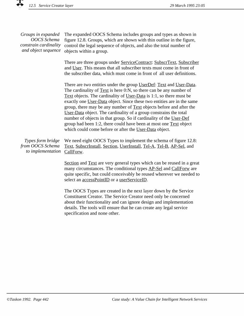
The expanded OOCS Schema includes groups and types as shown in figure 12.8. Groups, which are shown with thin outline in the figure, control the legal sequence of objects, and also the total number of objects within a group.
There are three groups under ServiceContract: SubscrText, Subscriberand User. This means that all subscriber texts must come in front of the subscriber data, which must come in front of all user definitions.
There are two entities under the group UserDef: Text and User-Data. The cardinality of Text is here 0:N, so there can be any number of Text objects. The cardinality of User-Data is 1:1, so there must be exactly one User-Data object. Since these two entities are in the same group, there may be any number of Text objects before and after the User-Data object. The cardinality of a group constrains the total number of objects in that group. So if cardinality of the User-Def group had been 1:2, there could have been at most one Text object which could come before or after the User-Data object.
Groups in expanded OOCS Schema
constrain cardinalityand object sequence
Types form bridge from OOCS Schema
to implementation
We need eight OOCS Types to implement the schema of figure 12.8: Text, SubscrInstall, Section, UserInstall, Tel-A, Tel-B, AP-Sel, and CallForw.
Section and Text are very general types which can be reused in a greatmany circumstances. The conditional types AP-Sel and CallForw are quite specific, but could conceivably be reused wherever we needed toselect an accessPointID or a userServiceID.
The OOCS Types are created in the next layer down by the Service Constituent Creator. The Service Creator need only be concerned about their functionality and can ignore design and implementation details. The tools will ensure that he can create any legal service specification and none other.
29 March 1995 23:0512.5 Service Creator layer
Case study: A Value Chain for Intelligent Network Services©Taskon 1992. Page 442

Conn-AEntity 0:1
TextEntity 0:N
TextType
ContractEntity 0:1
SubscrInstallType
ServicesGroup 0:N
AP-SelType
TextType
SubscrDataEntity 1:1
UserInstallType
SubscriberGroup 1:1
User-DataEntity 1:1
CallForwType
TextEntity 0:N
Tel-AType
AP-SelectorEntity 0:N
Conn-B-DataEntity 1:1
TextEntity 0:N
TextGroup 0:NText
Group 0:N
TextEntity 0:N
SectionType
SectionType
Conn-BGroup 1:1Conn-A
Group 1:1
Conn-A-DataEntity 1:1
Tel-BType
UserDefGroup 0:N
ConditionGroup 0:N
TextType
SectionType
TextType
ServiceContractType
UserEntity 0:N
CF-SelectorEntity 0:N
Conn-BEntity 0:N
SubscrTextGroup 0:N
UserGroup 0:N
Figure 12.8 Detailed OOCS Schema
12.5 Service Creator layer29 March 1995 23:05
Case study: A Value Chain for Intelligent Network Services ©Taskon 1992. Page 443

The Service Creator may define different OOCS Schemas for different categories of Service providers. One end of the spectrum could be the clerks in the corner Teleshop who get to use a small schema, which just permits them to specify the simple services they learned in their training course. Another end of the spectrum could be a highly competent customer consultant who gets to use a very elaborate schema that he knows how to exploit to tailor advanced services to the needs of his sophisticated customers.
Several Schemas canbe defined
Objects seem to be eminently suitable as information carriers on the upper four layers because they remember specific values set to the service parameters:
The Service Creator specifies OOCS Schemas, which define the services and all their permissible variants.
1.
The Service Provider instantiates the service objects, sets certain parameters, and installs them in the Subscriber's management object.
2.
The Subscriber duplicates the service objects, binds further parameters, and installs them with the User.
3.
4. The User duplicates the service objects, binds remaining parameters, and installs them in the network for execution.
29 March 1995 23:0512.5 Service Creator layer
©Taskon 1992. Page 444 Case study: A Value Chain for Intelligent Network Services
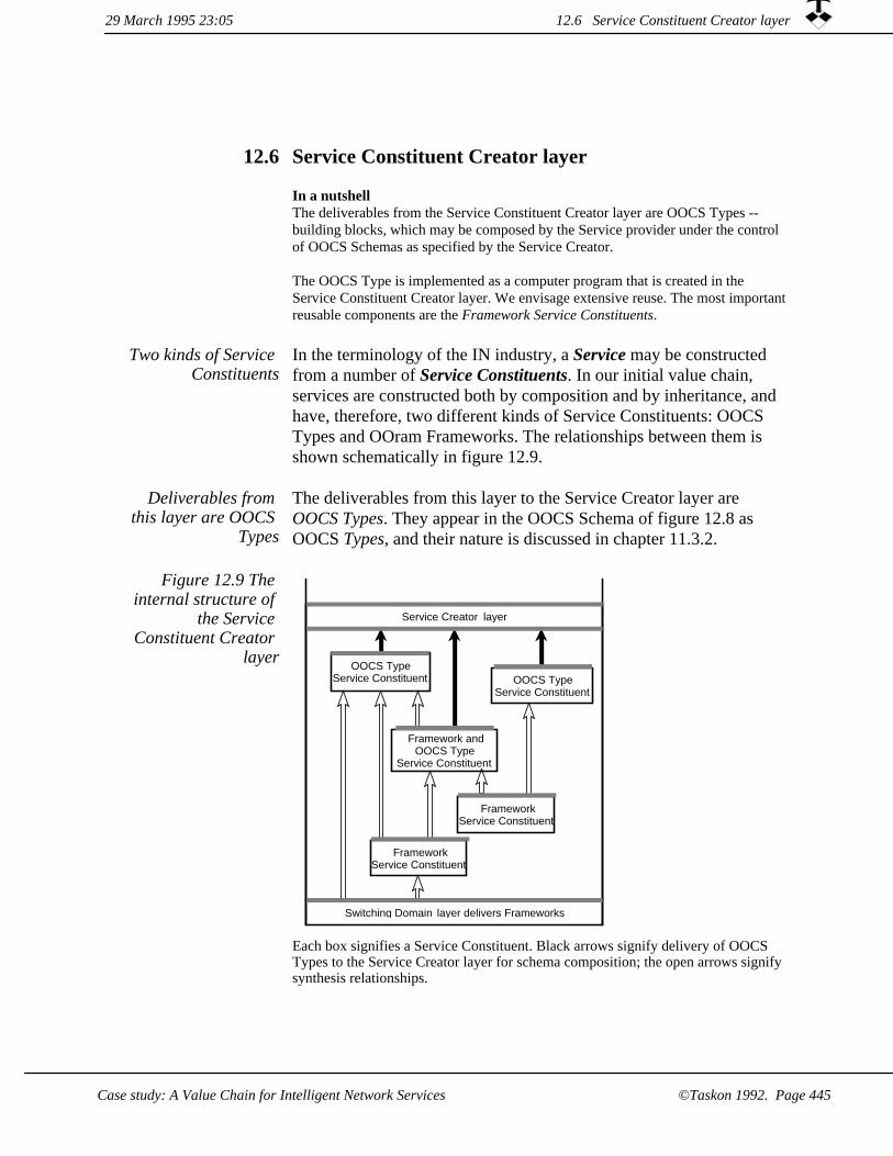
Service Constituent Creator layer12.6
In a nutshellThe deliverables from the Service Constituent Creator layer are OOCS Types -- building blocks, which may be composed by the Service provider under the control of OOCS Schemas as specified by the Service Creator.
The OOCS Type is implemented as a computer program that is created in the Service Constituent Creator layer. We envisage extensive reuse. The most importantreusable components are the Framework Service Constituents.
Two kinds of Service Constituents
In the terminology of the IN industry, a Service may be constructed from a number of Service Constituents. In our initial value chain, services are constructed both by composition and by inheritance, and have, therefore, two different kinds of Service Constituents: OOCS Types and OOram Frameworks. The relationships between them is shown schematically in figure 12.9.
Deliverables from this layer are OOCS
Types
The deliverables from this layer to the Service Creator layer are OOCS Types. They appear in the OOCS Schema of figure 12.8 as OOCS Types, and their nature is discussed in chapter 11.3.2.
OOCS TypeService Constituent
Service Creator layer
Switching Domain layer delivers Frameworks
FrameworkService Constituent
OOCS TypeService Constituent
FrameworkService Constituent
Framework andOOCS Type
Service Constituent
Figure 12.9 The internal structure of
the Service Constituent Creator
layer
Each box signifies a Service Constituent. Black arrows signify delivery of OOCS Types to the Service Creator layer for schema composition; the open arrows signify synthesis relationships.
29 March 1995 23:05 12.6 Service Constituent Creator layer
©Taskon 1992. Page 445Case study: A Value Chain for Intelligent Network Services

Consider object #107-1 Tel-A in the sample object structure of figure 12.3. This object appears as different roles in a number of different descriptions:
A typical object playsmany roles
1. It is a copy of the master object #107 Tel-A in figure 12.3.
It is an entity Conn-A-Data in the OOCS Schema of figure 12.8.2.
It is a type Tel-A in the OOCS Schema of figure 12.8.3.
It is configurable according to the mechanisms used for Schema composition.
4.
The design of its service functionality is specified in a role model,POTS-A, which will be described briefly below.
5.
It has a class which implements the calling end of a POTS communication channel.
6.
It exploits the functionality of the switching Domain by playing the role of Client to the Switch Connection framework, which is adeliverable from the Network Provider Layer.
7.
Framework Service Constituents organized in
Modules
A Framework Service Constituent is usually described by several role models and object specifications, and the Framework Service Constituent is a natural candidate for being packaged in a module.
A Framework Service Constituent module may import one or more frameworks from other Framework Service Constituent modules and may export frameworks to other Framework Service Constituent modules. On the top level, we find OOCS Types that are used as building blocks in the schemas of the Service Creator layer.
The implementation of our tiny initial system consists of 38 application-specific classes with 314 methods as shown in the program statistics in table 12.1. There are only six modules, module Network is the deliverable from the Network Provider layer and the others are organized in Service Constituent Creator sublayers as shown in figure 12.10 and described below:
1. User. This module defines the experimental user interfaces. The module does not export to the Service Creator layer because this part of the system is not configurable in our initial system.
2. Tel-A. This module defines the called part of POTS including the access point selection and call forward functionality. In a full size system, these latter functions would be factored out into two separate modules to make them available for reuse.
29 March 1995 23:0512.6 Service Constituent Creator layer
©Taskon 1992. Page 446 Case study: A Value Chain for Intelligent Network Services

3. Tel-B. This module defines the calling part of POTS, and is responsible for actually establishing the connection in the Switching Domain in our initial system. It imports the Switch Connection framework from the Network Provider layer.
Abstr-Tel. This module exports a mechanism which describes how the calling and called parts of the service interact in general terms. The mechanism is imported by the TelA and TelB modules.
4.
Invocation. This module exports a framework, which defines the environment of the service objects.
5.
Network. This module belongs in the Network Provider layer andexports frameworks for switch connections and other switch services.
6.
Table 12.1 Program statistics for the
application specific classes
Classcount
Averageinheritance
depth
Methodscount
Linescount
Changecount
Demonstration system 38 4.66 314 988 101
OOCS Schema
Service SpecificationContract
Service Objects
IN ServiceLayers
ServiceInformation Entities
Tel-A
Network
Invocation
Tel-B
Network ProviderLayer
Service ConstituentCreation Layer
Service CreatorLayer
Service ProviderLayer
User and SubscriberLayers
User
Abst-Tel
Figure 12.10 Modulestructure in the
initial value chain
A box signifies a Service Constituent. Black arrows signify delivery to the layer above; open arrows signify synthesis relationships within the Service Constituent Creator layer.
12.6 Service Constituent Creator layer29 March 1995 23:05
Case study: A Value Chain for Intelligent Network Services ©Taskon 1992. Page 447

The real module structure must be
carefully constructed
As the system is scaled up towards real size and the service specifications are expanded into real services, it will be necessary to organize the Service Constituents in a large number of modules and toassign these modules to well defined sublayers within the Service Constituent Creator layer.
An effective architecture for the Service Constituent Creator sub-layers with appropriate standards will create business opportunities fora rich variety of reusable patterns and frameworks.
29 March 1995 23:0512.6 Service Constituent Creator layer
©Taskon 1992. Page 448 Case study: A Value Chain for Intelligent Network Services

Network Provider layer12.7
In a nutshellThe Network Provider layer presents the functionality of the actual switches in a unified, implementation-independent manner to the Service Domain software, and makes its functionality available to the Service Constituent Creator in the form of one or more frameworks.
The Switching Domain is implemented as a very large, very high capacity, very fast, and very reliable heterogeneous distributed real time system. Communication channels are established by establishing paths between the Users through the switches. Figure 12.11 illustrateshow six Users are interconnected through four switches in a conference connection.
The purpose of the interface between the Switching Domain and the Service Domain is to hide the distributed nature of the communicationnetwork and to present a simple, abstract model of the network capabilities.
The deliverables from the Network Provider layer are a number of frameworks describing the offered functionality together with the corresponding implementation. We will give one example, the Connection Control framework.
The deliverables from the Network
layer
Figure 12.11 Simplified picture of
how six Users are interconnected
through a conferenceconnection B
A
D3D2D1
C3C2C1
B3B2B1
A3A2A1
D
C
29 March 1995 23:05 12.7 Network Provider layer
©Taskon 1992. Page 449Case study: A Value Chain for Intelligent Network Services

One such framework is based on the Connection Control model, which was briefly described in section 12.1. The distributed switches are abstracted into a single Connection Point, each communication channel from a user to this Connection Point is abstracted into a Leg. The Area of Concern is shown in figure 12.12. The Collaboration view in figure 12.13.
The Connection Control model
Figure 12.12 Connection Control -
- Area of concern
An abstract interface to the Switching Domain which offers connection functionalityin an implementation independent form.
Figure 12.13 Connection Control -- Collaboration view
il le
leg
ler
cp
cpr
ConnUser
Leg
Requests provision of connections between end-users, and between end-users and points in the network.
Leg provides a communication path towards an addressable network entity, as viewed from the Connection User (eg., an end-user, an information sink or source).
ConnPoint
Connection Point provides an interconnection of legs that allows information to flow between legs, as viewed from the Connection User.
ConnUser may be specialized, i.e. synthesized with other roles.Leg and ConnPoint are immutable roles, i.e., roles that cannot be modified in the derived model. The symbol for immutable roles is a role symbol with a double boundary as shown in the figure.
As seen from the Service Constituent layer, this model must permit the specialization of the ConnUser role through synthesis. The Leg and ConnPoint roles must be immutable because they can not be modified in the derived models. The model will have been implemented in the Network Provider layer, and the class corresponding to ConnUser must be available for subclassing while the other classes must be immutable. These constraints could, for example, be imposed by the compiler, or they may be checked by automatically analyzing the source code.
12.7 Network Provider layer 29 March 1995 23:05
Case study: A Value Chain for Intelligent Network Services©Taskon 1992. Page 450

We see that the complex realities of the Switching Domain are effectively hidden in the frameworks offered to the Service Constituent Creators. This means that they can focus on their main goal, which is to create powerful service components, and do not needto worry about the complex technical details of the switches. We also see that the frameworks can help enforce various constraints that are needed to protect the integrity of the switching network. This is done by insisting that all access to the network is through validated classes, which may not be modified (subclassed) by the Service Constituent Creator.
Frameworks hides Switching Domain
details and protects integrity
12.7 Network Provider layer29 March 1995 23:05
©Taskon 1992. Page 451Case study: A Value Chain for Intelligent Network Services

29 March 1995 23:0512.7 Network Provider layer
Case study: A Value Chain for Intelligent Network Services©Taskon 1992. Page 452

Appendix AThe OOram Language
The OOram technology has been developed around an object oriented data base, and the preferred user tools have task oriented, direct manipulation graphical user interfaces. It is nevertheless useful to define a textual form for all OOram model information, and it is the preferred form for some purposes such as documenting interfaces and role attributes.
This appendix defines a first version of the OOram language. The language serves three purposes:
As a summary of the OOram concepts and the relationships between them.1.
As a language for the precise documentation OOram models on paper.2.
3. As an interchange language for communicating OOram models, e.g. through electronic mail and between different implementations of OOramCASE tools.
We present the lexical conventions of the OOram language in Appendix A1, its grammar in Appendix A2 and its scoping rules in Appendix A3. The OOram semantics is defined in the main body of this book, particularly in chapters 2.5: Basic OOram role modeling concepts and notation, 3.3: Basic OOram concepts and notation for role model synthesis, and 6: Additional role modeling concepts and notation. We shall assume that the correspondence between the concepts defined there and the constructs of the language defined in the following will be clear from the chosen keywords etc.
The examples and case studies presented in this book have been specified in the TASKON/OOram tools, the book itself has been written with the TASKON/OOram documentation tool, and the diagrams and other OOram views have been automatically created by the tools. Appendix A4 contains an OOram language specification of the module which forms the basis of chapter 7: Case study: Development of a business information system, and A5 is similarly the specification of a module which includes some of the models of chapter 3: Role model synthesis.
A text describing an OOram model in the OOram language will be called an OOram specification.
29 March 1995 23:05
The OOram Language ©Taskon 1992. Page 453

A1 Lexical conventions
This section presents the lexical conventions of the OOram language, defining the structure ofthe tokens used, and the correspondence between a sequence of tokens and how it can be described by a string of characters.
The OOram language uses the ISO Latin-1 character set [ISO8859.1]. This character set is divided into alphabetic characters (letters), digits, graphic characters, the Space (blank) character and formatting characters (CR, LF, FF, and TAB).
If the input character string has been parsed into a token up to a given character, then any following spaces, formatting characters and comments (see below) will be skipped. Thereafter the next token is taken to be the longest string of characters that could possibly constitute a token.
Comments can occur anywhere between tokens. The characters /* start a comment, and it is terminated with the characters */. Comments do not nest. Comments may contain alphabetic, digit, graphic, space, and formatting characters. We recommend the convention that comments are printed in an italic font, but this has no formal significance.
The language uses the following kinds of tokens: separators, keywords, identifiers, string literals, and integer literals.
SeparatorsA1.1
OOram specifications use the separator tokens shown in table A1.
| ( ) , :: <- >> \n
Table A1 OOram punctuation tokens
KeywordsA1.2
The words listed in table A2 are the keywords of the language. Upper and lower case letters are considered equivalent in keywords. For example, module, Module, and MODULE are all considered equivalent. We recommend the convention that keywords are printed in a bold font, but this has no formal significance.
A1 Lexical conventions 29 March 1995 23:05
©Taskon 1992. Page 454 The OOram Language
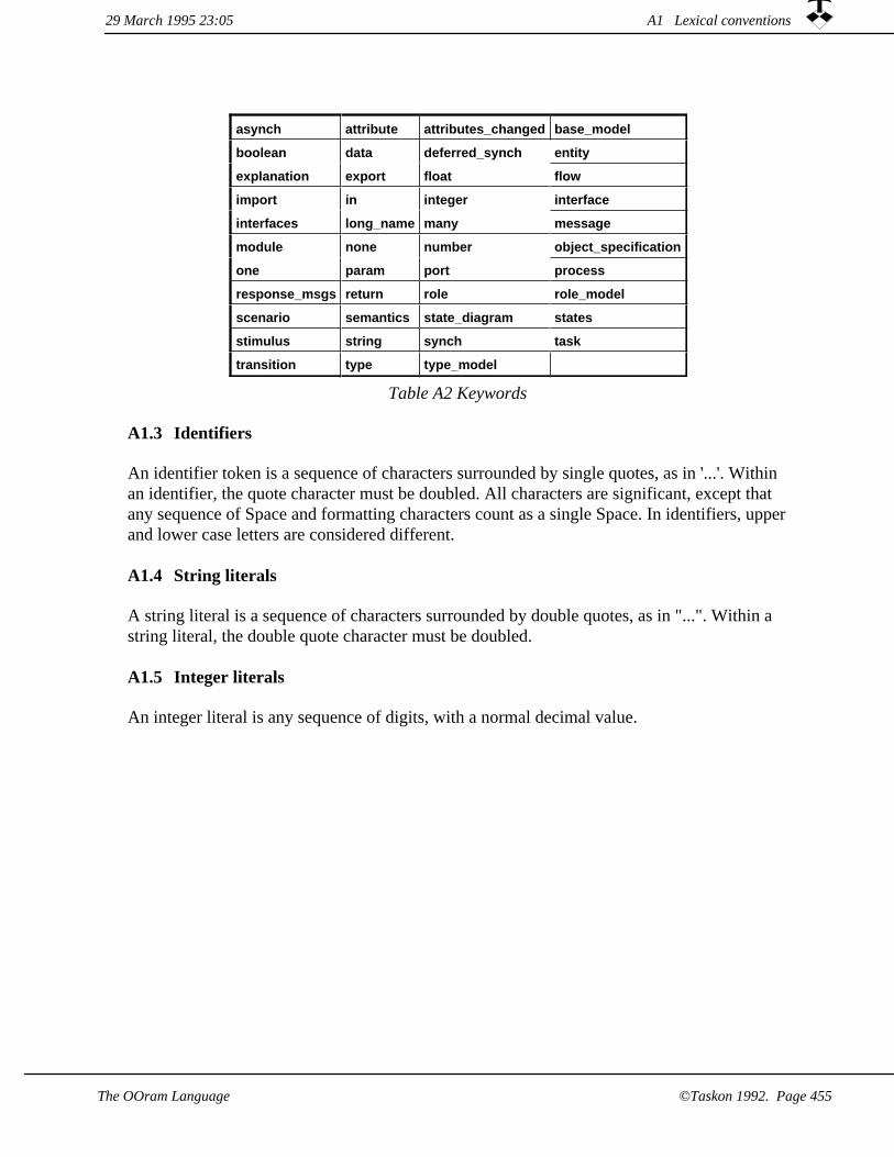
asynch attribute attributes_changed base_model
boolean data deferred_synch entity
explanation export float flow
import in integer interface
interfaces long_name many message
module none number object_specification
one param port process
response_msgs return role role_model
scenario semantics state_diagram states
stimulus string synch task
transition type type_model
Table A2 Keywords
IdentifiersA1.3
An identifier token is a sequence of characters surrounded by single quotes, as in '...'. Within an identifier, the quote character must be doubled. All characters are significant, except that any sequence of Space and formatting characters count as a single Space. In identifiers, upperand lower case letters are considered different.
String literalsA1.4
A string literal is a sequence of characters surrounded by double quotes, as in "...". Within a string literal, the double quote character must be doubled.
A1.5 Integer literals
An integer literal is any sequence of digits, with a normal decimal value.
29 March 1995 23:05 A1 Lexical conventions
©Taskon 1992. Page 455The OOram Language

OOram language grammarA2
he syntax notation used in this grammar is a variation of the Extended Backus-Naur format. Table A3 lists the symbols used and their meaning. Two types of non-terminals are used: Those given with upper case letters indicate that a token of this category should occur here. The others are normal non-terminals that are defined elsewhere in the grammar.
Symbol Meaning
::= is defined to be
| alternatively
<text> a normal non-terminal
<TEXT> a non-terminal indicating a token of the given category
"text" the text directly identifies a keyword or separator
* the preceding syntactic unit can be repeated zero or more times
+ the preceding syntactic unit can be repeated one or more times
{ } The enclosed syntactic units are grouped as a single syntactic unit
[ ] The enclosed syntactic unit is optional -- may occur zero or one time
Table A3 The symbols of the OOram Extended Backus-Naur format and their meaning.
In an OOram specification, some occurrences of identifiers will serve to associate this identifier with the entity described by the corresponding syntactical construct; while others serve as references to entities described elsewhere. The occurrences of the former type are highlighted in the syntax below by giving the corresponding (normal) non-terminal in italics, e.g. <rm_name>. The association obtained in this way will have effect throughout the closest surrounding "scoping construct" in which the definition occurs. Exactly what constructs that qualify as scoping constructs is described in section A.3.
::= <module>+<specification>
::= "module" <module_name> <import_model>* <export_model>* <rm_definition>*<module>
::= <IDENTIFIER><module_name>
<import_model> ::= "import" <rm_name> "<-" <rm_name> "::" <module_name>
::= <IDENTIFIER><rm_name>
<export_model> ::= "export" <rm_name>
::= <rm_kind> <rm_name> <node_descr> <rm_spec>*<rm_definition>
::= "role_model"| "object_specification"| "type_model"
<rm_kind>
::= [<long_name>] [<explanation>]<node_descr>
::= "base_model" <rm_name> <inherit_map>* | "interface" <interface_name> <node_descr> <interface_spec>*| "role" <role_name> <node_descr> <role_spec>* | "scenario" <scenario_name> <node_descr> <interaction>* | "process" <process_name> <node_descr> {<task> | <entity> }* <flow>*
<rm_spec>
::= "long_name" <STRING_LITERAL><long_name>
A2 OOram language grammar 29 March 1995 23:05
©Taskon 1992. Page 456 The OOram Language

::= "explanation" <STRING_LITERAL><explanation>
::= <base_role_name> "->" <derived_role_name> <inherit_map>
::= <IDENTIFIER><interface_name>
<interface_spec> ::= <type_dcl> | <message_spec>
<role_name> ::= <IDENTIFIER>
<attribute_spec>| <stimulus>*| <port_spec>| <state_diagram_spec>
<role_spec> ::=
::= "stimulus" <scoped_message_name> [<explanation>] ["response_msgs" "(" <scoped_message_names> ")"] ["attributes_changed" "(" <scoped_attribute_names> ")"]
<stimulus>
<scoped_message_names>
::= <scoped_message_name> {"," <scoped_message_name> }*
<scoped_message_name> ::= <message_name> ["::" <interface_name>]
::= <scoped_attribute_name> {"," =<scoped_attribute_name> }*
<scoped_attribute_names>
<scoped_attribute_name> ::= <attribute_name> [ "::" <role_name> ]
::= <IDENTIFIER><scenario_name>
<interaction> ::= <role_name> ">>" <message_name> ">>" <role_name>
::= <IDENTIFIER><process_name>
::= "task" <task_name> <node_descr> "in" <role_name>| "task" "stimulus" <task_name> <node_descr> "in" <role_name>
<task>
<task_name> ::= <IDENTIFIER>
::= "entity" <entity_name> <node_descr> "data" <data_list><entity>
::= <IDENTIFIER><entity_name>
<data_list> ::= "(" <data_name> {"," <data_name> }* ")"
::= <IDENTIFIER><data_name>
::= "flow" <from_task> ">>" ">>" <to_task>| "flow" <from_task> ">>" <entity_name> ">>" <to_task>
<flow>
::= <task_name><from_task>
<to_task> ::= <task_name>
::= <role_name><base_role_name>
::= <role_name><derived_role_name>
<message_spec> ::= "message" [<message_semantics>] <message_name> <node_descr> <parameter>*
::= "attribute" <attribute_name> <node_descr> [ "type" <type_dcl>]<attribute_spec>
::= <base_type>| <scoped_role_name>
<type_dcl>
::= "port" <cardinality> <port_name> <node_descr> ["semantics" <min_count> ":" <max_count> [<explanation>]] ["interfaces" "(" <interface_names> ")"]
<port_spec>
::= <INTEGER_LITERAL><min_count>
<max_count> ::= <INTEGER_LITERAL>
::= "state_diagram" <state_specs> <transition>*<state_diagram_spec>
<message_name> ::= <IDENTIFIER>
::= "float"| "integer"| "boolean"| "string"
<base_type>
A2 OOram language grammar29 March 1995 23:05
The OOram Language ©Taskon 1992. Page 457

::= <role_name> ["::" <rm_name>]<scoped_role_name>
::= "synch"| "deferred_synch"| "asynch"
<message_semantics>
::= "param" <param_name> [<explanation>] ["type" <type_dcl>]| "return" [<explanation>] ["type" <type_dcl>]
<parameter>
::= <IDENTIFIER><attribute_name>
<cardinality> ::= "none"| "one"| "many"
<port_name> ::= <IDENTIFIER>
::= [<interface_name> {"," <interface_name> }*] <interface_names>
<param_name> ::= <IDENTIFIER>
::= "states" "(" [ <state_name> {"," <state_name>}*] ")"<state_specs>
::= <IDENTIFIER><state_name>
<transition> ::= "transition" <initial_state_name> <message_name> <action list> <next_state_name>
::= <state_name><initial_state_name>
<action_list> ::= "(" [ <action_name> { "," <action_name> }* ] ")"
::= <IDENTIFIER><action_name>
::= <state_name><next_state_name>
A2 OOram language grammar 29 March 1995 23:05
The OOram Language©Taskon 1992. Page 458

A3 Scope of identifiers
As explained earlier, some occurrences of identifiers in an OOram specification serve to associate that identifier with the entity described by the corresponding language construct. This association will have effect throughout the closest surrounding "scoping construct" in which the definition occurs (also textually in front of the definition). Thus, from within its scoping construct an entity may be referenced directly by its identifier. By using "scoped names" entities may also be referenced from outside their scoping construct. The scoped name x::y should be understood as the entity named x defined local to the scoping construct named y.
The syntactical units that qualify as scoping constructs are the following: Modules, role_models, interfaces, messages, and roles. In the grammar above these constructs are identified by their initial keyword, and they are always nested as indicated in figure A1. In this figure we have also indicated what name-types are local to the different scoping constructs. Note that the name of a scoping construct is itself local to the nearest enclosing scoping construct.
Local to one scoping construct, no two entities can be identified by the same name. However,local to two different scoping constructs the same names may be used, even if they are nested. A referencing occurrence of a name will always identify the entity with that name local to the nearest possible enclosing scoping construct.
"module"
<scenario_name><role_name><interface_name>
<rm_name>
<module_name>
"role_model"
"interface"
<param_name>
<message_name>
"message"
<port_name><attribute_name>
"role" "process_name"
<task_name><entity_name><data_name><state_name>
<action_name>
Figure A1 The scope of the different OOram identifiers.
When an OOram model is represented as a structure of objects, the different entities are identified by their object identifiers. The names that users assign to the entities help the users understand the models, but have no formal significance.
A3 Scope of identifiers29 March 1995 23:05
©Taskon 1992. Page 459The OOram Language

If the model is used to generate code in a programming language, the names are used to generate identifiers in the selected programming language. The wise analyst will then use entity names that may be used unchanged as program identifiers to make the relationship between model and program as evident as possible. Our modeling tools support this by warning the analyst if a chosen name does not conform to the syntax and pragmatics of the chosen language. The tools will also warn the analyst about duplicate names which would cause compilation errors if used unchanged.
When an OOram model is represented as a string of characters, we could have retained the object identifiers as the real identifiers of the different entities. These identifiers are typically quite unreadable to a human, and the OOram language is designed so that the entities are identified by their names. The kind of entity determines the scope of these names as illustrated in figure A1.
29 March 1995 23:05A3 Scope of identifiers
©Taskon 1992. Page 460 The OOram Language

A4 OOram module 'Development of a business information system Chapter'
module 'Travel Expense case study'
export 'Travel Expense Enterprise Model'
role_model 'Travel Expense Enterprise Model'explanation "The area of concern is the handling of travel expense accounts. We focus on the expense account itself,
and do not model details about why the journey was made, nor how the traveler is reimbursed for his expenses.'interface 'ENTPaymaster<ENTBookkeeper'
message synch 'paymentRequest:' explanation "Reimburse the specified account."param 'aPaymentRequest' type 'INFPayRequest' :: 'Travel Expense Information Model'
interface 'ENTTraveler<ENTAuthorizer' message synch 'travelPermission:'
explanation "Travel authorization granted."param 'aTravelPermission' type 'INFTravelPermission' :: 'Travel Expense Information Model'
interface 'ENTBookkeeper<ENTAuthorizer' message synch 'authorizedExpenseReport:'
explanation "Request reimbursement of submitted expense report."param 'anExpenseReport' type 'INFExpenseAccount' :: 'Travel Expense Information Model'
interface 'ENTAuthorizer<ENTTraveler' message synch 'travelPermissionRequest:'
explanation "Request authorization of submitted travel plan."param 'aTravelPermission' type 'INFTravelPermission' :: 'Travel Expense Information Model'
message synch 'expenseReport:' explanation "Request reimbursement of submitted expense report."param 'anExpenseReport' type 'INFExpenseAccount' :: 'Travel Expense Information Model'
role 'ENTTraveler' explanation "The person who travels"stimulus 'travelPermissionRequest:' :: 'ENTAuthorizer<ENTTraveler'
response_msgs ( 'paymentRequest:' :: 'ENTPaymaster<ENTBookkeeper' )attributes_changed ( )
port one 'au' interfaces ( 'ENTAuthorizer<ENTTraveler') role 'ENTAuthorizer'
explanation "The person who authorizes the travel."port many 'tr' interfaces ( 'ENTTraveler<ENTAuthorizer') port one 'bo' interfaces ( 'ENTBookkeeper<ENTAuthorizer')
role 'ENTBookkeeper' explanation "The person responsible for bookkeeping."port one 'pm' interfaces ( 'ENTPaymaster<ENTBookkeeper')
role 'ENTPaymaster' explanation "The person responsible for reimbursement."
process 'ExpenseAccount Process diagram' task stimulus 'stimulus'
explanation "Desire to travel"in 'ENTTraveler'
entity 'travelPermissionRequest:' data ( aTravelPermission )
task 'travelPermissionRequest:' explanation "<Determine OK>"in 'ENTAuthorizer'
entity 'travelPermission:' data ( aTravelPermission )
task 'travelPermission:' explanation "<Order tickets> <Travel> <Write exp.rep.>"in 'ENTTraveler'
entity 'expenseReport:' data ( anExpenseReport )
task 'expenseReport:' explanation "<Check OK>"in 'ENTAuthorizer'
entity 'authorizedExpenseReport:' data ( anExpenseReport )
A4 OOram module 'Development of ... information system Chapter'29 March 1995 23:05
The OOram Language ©Taskon 1992. Page 461
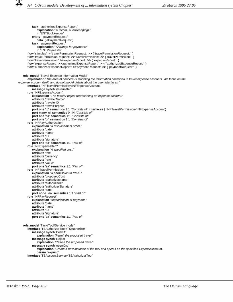
task 'authorizedExpenseReport:' explanation "<Check> <Bookkeeping>"in 'ENTBookkeeper'
entity 'paymentRequest:' data ( aPaymentRequest )
task 'paymentRequest:' explanation "<Arrange for payment>"in 'ENTPaymaster'
flow 'stimulus' >>'travelPermissionRequest:' >> ( 'travelPermissionRequest:' ) flow 'travelPermissionRequest:' >>'travelPermission:' >> ( 'travelPermission:' ) flow 'travelPermission:' >>'expenseReport:' >> ( 'expenseReport:' ) flow 'expenseReport:' >>'authorizedExpenseReport:' >> ( 'authorizedExpenseReport:' ) flow 'authorizedExpenseReport:' >>'paymentRequest:' >> ( 'paymentRequest:' )
role_model 'Travel Expense Information Model' explanation "The area of concern is modeling the information contained in travel expense accounts. We focus on the
expense account itself, and do not model details about the user interfaces."interface 'INFTravelPermission<INFExpenseAccount'
message synch 'isPermitted' role 'INFExpenseAccount'
explanation "The master object representing an expense account."attribute 'travelerName'attribute 'travelerID'attribute 'travelPurpose'port one 'tp' semantics 1:1 "Consists of" interfaces ( 'INFTravelPermission<INFExpenseAccount') port many 'ei' semantics 0 : N "Consists of"port one 'pa' semantics 1:1 "Consists of"port one 'pr' semantics 1:1 "Consists of"
role 'INFPayAuthorization' explanation "A disbursement order."attribute 'date'attribute 'name'attribute 'ID'attribute 'signature'port one 'ea' semantics 1:1 "Part of"
role 'INFExpenseItem' explanation "A specified cost."attribute 'text'attribute 'currency'attribute 'rate'attribute 'value'port one 'ea' semantics 1:1 "Part of"
role 'INFTravelPermission' explanation "A permission to travel."attribute 'proposedCost'attribute 'authorizerName'attribute 'authorizerID'attribute 'authorizerSignature'attribute 'date'port none 'ea' semantics 1:1 "Part of"
role 'INFPayRequest' explanation "Authorization of payment."attribute 'date'attribute 'name'attribute 'ID'attribute 'signature'port one 'ea' semantics 1:1 "Part of"
role_model 'Task/Tool/Service model' interface 'TSAuthorizerTool<TSAuthorizer'
message synch 'Permit' explanation "Permit the proposed travel"
message synch 'Reject' explanation "Refuse the proposed travel"
message synch 'openOn:' explanation "Create a new instance of the tool and open it on the specified ExpenseAccount."param 'expAcc'
interface 'TSAccountService<TSAuthorizerTool'
A4 OOram module 'Development of ... information system Chapter' 29 March 1995 23:05
©Taskon 1992. Page 462 The OOram Language

message synch 'getExpenseAccount' explanation "Return expense account information"return type 'INFExpenseAccount' :: 'Travel Expense Information Model'
message synch 'getPeriod' explanation "Return travel time period"
message synch 'getPlannedCost' explanation "Returned planned cost"
message synch 'getPurpose' explanation "Return purpose of travel"
message synch 'putAuthorized:' explanation "Set authorization if aBoolean = true, otherwise the travel is rejected."param 'aBoolean' type boolean
interface 'TSBudgetService<TSAuthorizerTool' message synch 'getBudgetFor:'
explanation "Return budget information"param 'kind'return type number
message synch 'commit:for:' explanation "Allocate amount from budget"param 'amount' type number param 'kind'
interface 'TSAuthorizer<TSAuthorizerTool' message synch 'display'
explanation "Read the currently displayed text."interface 'TSPlanningService<TSAuthorizerTool'
message synch 'getPlanFor:' explanation "Return planning information"param 'person'return type 'Plan' :: 'BasicTypes'
role 'TSAuthorizer' explanation "The person who authorizes the travel."stimulus 'openOn:' :: 'TSAuthorizerTool<TSAuthorizer'port one 'tool' interfaces ( 'TSAuthorizerTool<TSAuthorizer')
role 'TSAuthorizerTool' explanation "The user interface system"port one 'auth' interfaces ( 'TSAuthorizer<TSAuthorizerTool') port one 'bud' interfaces ( 'TSBudgetService<TSAuthorizerTool') port one 'pla' interfaces ( 'TSPlanningService<TSAuthorizerTool') port one 'acc' interfaces ( 'TSAccountService<TSAuthorizerTool')
role 'TSAccountService' explanation "An object structure representing a particular expense account."
role 'TSPlanningService' explanation "A system representing the current plans for the enterprise"
role 'TSBudgetService' explanation "A system managing the enterprise budget"
process 'OpenPermissionTool' task stimulus 'stimulus'
explanation "Start authorization activity"in 'TSAuthorizer'
task 'openOn:' explanation "Create and open travel authorization tool"in 'TSAuthorizerTool'
task 'getExpenseAccount' explanation "getExpenseAccount"in 'TSAccountService'
entity 'ISExpenseAccount' data ( expAcc )
task 'getBudgetFor:' explanation "getBudgetFor:"in 'TSBudgetService'
entity 'Budgetamount' data ( expAcc )
task 'getPlanFor:' explanation "getPlanFor:"in 'TSPlanningService'
entity 'Plan' data ( expAcc )
flow 'stimulus' >> >> ( 'openOn:' ) flow 'openOn:' >> >> ( 'getExpenseAccount' ) flow 'openOn:' >> >> ( 'getBudgetFor:' )
29 March 1995 23:05 A4 OOram module 'Development of ... information system Chapter'
The OOram Language ©Taskon 1992. Page 463

flow 'openOn:' >> >> ( 'getPlanFor:' ) flow 'getExpenseAccount' >>'ISExpenseAccount' >> ( 'openOn:' ) flow 'getBudgetFor:' >>'Budgetamount' >> ( 'openOn:' ) flow 'getPlanFor:' >>'Plan' >> ( 'openOn:' ) process 'GrantPermission'
task stimulus 'stimulus' explanation "Press Permit- button"in 'TSAuthorizer'
task 'Permit' explanation "Grant Permission"in 'TSAuthorizerTool'
task 'putAuthorized:' explanation "putAuthorized: = true"in 'TSAccountService'
entity 'true' data ( aBoolean )
task 'commit:for:' explanation "Record new commitment"in 'TSBudgetService'
entity 'Number' data ( amount )
flow 'stimulus' >> >> ( 'Permit' ) flow 'Permit' >>'true' >> ( 'putAuthorized:' ) flow 'Permit' >>'Number' >> ( 'commit:for:' )
A4 OOram module 'Development of ... information system Chapter' 29 March 1995 23:05
The OOram Language©Taskon 1992. Page 464

OOram module 'Synthesis'A5
module 'Some Synthesis Models'
import 'Travel Expense Enterprise Model' <- 'Travel Expense Enterprise Model' :: 'Work Environments'
role_model 'BasicTree' explanation "A role model describing a basic tree structure."interface 'Child<Mother'
message synch 'preorderTraverse:' param 'aBlock'message synch 'postorderTraverse:' param 'aBlock'message synch 'getLeaves'
interface 'Mother<Child' message synch 'getRoot'
role 'Mother' port many 'dw' interfaces ( 'Child<Mother')
role 'Child' port one 'up' interfaces ( 'Mother<Child')
role_model 'ThreeLevelTree' explanation "A role model describing a tree structure with three levels."base_model 'BasicTree'
'Mother' -> 'Node''Child' -> 'Leaf'
base_model 'BasicTree''Mother' -> 'Root''Child' -> 'Node'
role 'Root' port many 'dw'
role 'Node' port one 'up' port many 'dw'
role 'Leaf' port one 'up'
role_model 'AirlineBooking' explanation "Airline tickets are ordered by a booking clerk and paid directly to the travel agent. The traveler is to show
the cost of the tickets on the expense report as an expense, and as an advance since the tickets were not paid by the traveler."interface 'ABTravelAgent<ABPaymaster'
message synch 'payment:' explanation "Transmittal of payment."param 'aCheque' type string
interface 'ABBookKeeper<ABBookingClerk' message synch 'authorizedInvoice:'
explanation "Pay this authorized ticket invoice."param 'anInvoice' type string
interface 'ABTraveler<ABBookingClerk' message synch 'ticketWithCost:'
explanation "Transmitting the ticket(s) together with cost information."param 'package' type string
interface 'ABTravelAgent<ABBookingClerk' message synch 'orderTicket:'
explanation "Reserve specified passages and issue ticket(s)."param 'ticketSpecification' type string
interface 'ABPaymaster<ABBookKeeper' message synch 'paymentRequest:'
explanation "Pay this invoice."param 'anInvoice' type string
interface 'ABBookingClerk<ABTraveler' message synch 'orderTicket:'
explanation "Purchase ticket(s)."param 'ticketSpecification' type string
interface 'ABBookingClerk<ABTravelAgent' message synch 'ticket:'
explanation "Transmittal of ticket(s)."
29 March 1995 23:05 A5 OOram module 'Synthesis'
The OOram Language ©Taskon 1992. Page 465

param 'aTicket' type string message synch 'invoice:'
explanation "Transmittal of invoice."param 'anInvoice' type string
role 'ABTraveler' explanation "The person who travels."attribute 'costOfTicket'stimulus 'orderTicket:' :: 'ABBookingClerk<ABTraveler'
response_msgs ( 'ticketWithCost:' :: 'ABTraveler<ABBookingClerk' )attributes_changed ( 'costOfTicket' )
port one 'sec' interfaces ( 'ABBookingClerk<ABTraveler') role 'ABBookingClerk'
explanation "Clerk responsible for managing the purchase of tickets."port one 'tr' interfaces ( 'ABTraveler<ABBookingClerk') port one 'ta' interfaces ( 'ABTravelAgent<ABBookingClerk') port one 'bk' interfaces ( 'ABBookKeeper<ABBookingClerk')
role 'ABTravelAgent' explanation "A travel agent."port one 'cust' interfaces ( 'ABBookingClerk<ABTravelAgent')
role 'ABBookKeeper' explanation "Responsible for accounting."port one 'pm' interfaces ( 'ABPaymaster<ABBookKeeper')
role 'ABPaymaster' explanation "Cashier."port one 'ven' interfaces ( 'ABTravelAgent<ABPaymaster')
process 'AirlineBooking process' task stimulus 'stimulus' explanation "Order tickets" in 'ABTraveler'entity 'Travelspecification1' data ( 'ticketSpecification' )task 'orderTicket' explanation "Order tickets" in 'ABBookingClerk'entity 'Travelspecification2' data ( 'ticketSpecification' )task 'issueTickets' explanation "Issue tickets. Prepare invoice." in 'ABTravelAgent'entity 'TicketsAndInvoice' data ( 'aTicket' )task 'processTickets' explanation "Process tickets and invoice" in 'ABBookingClerk'entity 'TicketsAndCost' data ( 'tickets and cost information' )task 'noteCost' explanation "Note cost for later use" in 'ABTraveler'entity 'Authorizedinvoice' data ( 'anInvoice' )task "processInvoice' explanation "Process invoice" in 'ABBookKeeper'entity 'RemunerationRequest' data ( 'anInvoice' )task 'pay' explanation "Send payment" in 'ABPaymaster'entity 'Payment' data ( 'aCheque' )task 'receivePayment' explanation "Receive payment" in 'ABTravelAgent'
flow 'stimulus' >>'Travelspecification1' >> ('orderTicket' ) flow 'orderTicket' >>'Travelspecification2' >> ( 'issueTickets' ) flow 'issueTickets' >>'TicketsAndInvoice' >> ( 'processTickets' ) flow 'processTickets' >>'TicketsAndCost' >> ( 'noteCost' ) flow 'processTickets' >>'Authorizedinvoice' >> ( 'processInvoice' ) flow 'processInvoice' >>'RemunerationRequest' >> ( 'pay' ) flow 'pay' >>'Payment' >> ( 'receivePayment' )
role_model 'DerivedTravelExpense' explanation "The area of concern is the procedure for travel management including the purchase of tickets."base_model 'AirlineBooking'
'ABBookKeeper' -> 'DTEBookKeeper''ABTravelAgent' -> 'DTETravelAgent''ABBookingClerk' -> 'DTEBookingClerk''ABPaymaster' -> 'DTEPaymaster''ABTraveler' -> 'DTETraveler'
base_model 'Travel Expense Enterprise Model''ENTPaymaster' -> 'DTEPaymaster''ENTAuthorizer' -> 'DTEAuthorizer''ENTTraveler' -> 'DTETraveler''ENTBookkeeper' -> 'DTEBookkeeper'
role 'DTETraveler' explanation "The person who travels."stimulus 'travelPermissionRequest:' :: 'ENTAuthorizer<ENTTraveler'
response_msgs ( 'paymentRequest:' :: 'ENTPaymaster<ENTBookkeeper' )attributes_changed ( )
port one 'sec' interfaces ( 'ABBookingClerk<ABTraveler') port one 'au'
29 March 1995 23:05A5 OOram module 'Synthesis'
The OOram Language©Taskon 1992. Page 466

role 'DTEBookingClerk' explanation "Clerk responsible for managing the purchase of tickets."port one 'bk' interfaces ( 'ABBookKeeper<ABBookingClerk') port one 'tr' interfaces ( 'ABTraveler<ABBookingClerk') port one 'ta' interfaces ( 'ABTravelAgent<ABBookingClerk')
role 'DTEBookKeeper' explanation "The person responsible for bookkeeping. Responsible for accounting."port one 'pm' interfaces ( 'ABPaymaster<ABBookKeeper')
role 'DTETravelAgent' explanation "A travel agent."port one 'cust' interfaces ( 'ABBookingClerk<ABTravelAgent')
role 'DTEPaymaster' explanation "The person responsible for reimbursement. Cashier."port one 'ven' interfaces ( 'ABTravelAgent<ABPaymaster')
role 'DTEAuthorizer' explanation "The person who authorizes the travel."port many 'tr' port one 'bo'
process 'ExpenseAccount Process diagram' task stimulus 'stimulus' explanation "Desire to travel" in 'DTETraveler'entity 'travelPermissionRequest:' data ( aTravelPermission )task 'travelPermissionRequest:' explanation "<Determine OK>" in 'DTEAuthorizer'entity 'travelPermission:' data ( aTravelPermission )task 'travelPermission:' explanation "<Order tickets>" in 'DTETraveler'task stimulus 'planTravel' explanation "Order tickets" in 'DTETraveler'entity 'Travelspecification1' data ( ticketSpecification )task 'orderTicket' explanation "Order tickets" in 'DTEBookingClerk'entity 'Travelspecification2' data ( ticketSpecification )task 'issueTickets' explanation "Issue tickets. Prepare invoice." in 'DTETravelAgent'entity 'TicketsAndInvoice' data ( aTicket )task 'processTickets' explanation "Process tickets and invoice" in 'DTEBookingClerk'entity 'TicketsAndCost' data ( tickets and cost information )task 'noteCost' explanation "<Note cost> <Travel> <Prepare expense account>" in 'DTETraveler'entity 'Authorizedinvoice' data ( anInvoice )task 'processInvoice' explanation "Process invoice" in 'DTEBookKeeper'entity 'RemunerationRequest' data ( anInvoice )task 'pay' explanation "Send payment" in 'DTEPaymaster'entity 'Payment' data ( aCheque )task 'receivePayment' explanation "Receive payment" in 'DTETravelAgent'entity 'expenseReport:' data ( anExpenseReport )task 'expenseReport:' explanation "<Check OK>" in 'DTEAuthorizer'entity 'authorizedExpenseReport:' data ( anExpenseReport )task 'authorizedExpenseReport:' explanation "<Check> <Bookkeeping>" in 'DTEBookkeeper'entity 'paymentRequest:' data ( aPaymentRequest )task 'paymentRequest:' explanation "<Arrange for payment>" in 'DTEPaymaster'
flow 'stimulus' >>'travelPermissionRequest:' >> ( 'travelPermissionRequest:' ) flow 'travelPermissionRequest:' >>'travelPermission:' >> ( 'planTravel' ) flow 'planTravel' >>'Travelspecification1' >> ( 'orderTicket' ) flow 'orderTicket' >>'Travelspecification2' >> ( 'issueTickets' ) flow 'issueTickets' >>'TicketsAndInvoice' >> ( 'processTickets' ) flow 'processTickets' >>'TicketsAndCost' >> ( 'noteCost' ) flow 'processTickets' >>'Authorizedinvoice' >> ( 'processInvoice' ) flow 'processInvoice' >>'RemunerationRequest' >> ( 'pay' ) flow 'pay' >>'Payment' >> ( 'receivePayment' ) flow 'noteCost' >>'expenseReport:' >> ( 'expenseReport:' ) flow 'expenseReport:' >>'authorizedExpenseReport:' >> ( 'authorizedExpenseReport:' ) flow 'authorizedExpenseReport:' >>'paymentRequest:' >> ( 'paymentRequest:' )
A5 OOram module 'Synthesis'29 March 1995 23:05
©Taskon 1992. Page 467The OOram Language

A5 OOram module 'Synthesis' 29 March 1995 23:05
©Taskon 1992. Page 468 The OOram Language

Appendix BReferences
[Alexander 77] Christopher Alexander: A Pattern Language. Oxford University Press, New York, 1977.
[Alexander 79] Christopher Alexander: The Timeless Way of Building. Oxford University Press, New York, 1979.
[E. Andersen 92] Egil P. Andersen, Trygve Reenskaug: System Design by Composing Structures of Interacting Objects. ECOOP '92, Utrecht, Holland.
[And 91] Jørn Andersen, Trygve Reenskaug: Operations on sets in an OODB. OOPS Messenger, 2, 4 (October 1991) pp. 26-39.
[Aronson 72] Elliot Aronson: The Social Animal. W. H. Freeman and Company, San Francisco 1972. ISBN 0-7167-0829-9
[Beck 86] O'Shea, T., Beck, K., Halbert, D., Schmucker, K. J. Panel on "The learnability of Object-Oriented Programming Systems". SIGPLAN Notices, 21, 11 (November 1986) p. 503.
[Beck 94] Kent Beck, Ralph Johnson: Patterns Generate Architectures. In: Tokoro, Pareschi (Eds): 8th European Conference on Object-Oriented Programming (ECOOP 94). Springer Verlag, 1994.
[Bent 86] See for example John Bentley: "Programming Pearls". Comm. ACM 29,5 (May 1986) p364-369 and Comm. ACM 30,4 (April 1987) p384-290.
[Berr93] Arne-Jørgen Berre: An Object-Oriented Framework for Systems Integration and Interoperability. PhD-thesis, University of Trondheim, Norwegian Institute of Technology, 1993, 370 pages.
[Birth 73] G. M. Birtwistle, O.-J. Dahl, B. Myrhaug, K. Nygaard: "Simula Begin". Auerbach/Studentlitteratur Lund 1973. ISBN 91-44-06211-7.
[Boehm 88] Barry W. Boehm: A Spiral Model of Software Development and Enhancement. Computer, May 1988, pp 61-72.
[Booch 91] Grady Booch: Object-Oriented Design with Applications. The Benjamin/Cummings Publishing Company.
29 March 1995 23:05
©Taskon 1992. Page 469References

[Booch 94] Grady Booch: Object-Oriented Analysis and Design with Applications. Second edition. The Benjamin/Cummings Publishing Company. ISBN 0-8053-5340-2
[Broc94] Kraig Brockschmidt: Inside OLE2. Microsoft Press, 1994, 977 pages
[Bræk 93] Rolv Bræk, Øystein Haugen: Engineering Real Time Systems. An object oriented methodology using SDL. Hemel Hempstead: Prentice Hall, 1993. ISBN 0-13-034448-6
[Car 85] L. Cardelli, P. Wegner: On Understanding Types, Data Abstracting and Polymorphism. Computing Surveys 17 (4) 471-522 (1985)
[CCITT Z100] Specification and Description Language SDL. Recommendation Z100. Geneva, ITU 1993.
[CCITT Z120] Message Sequence Charts. Recommendation Z120. Geneva, ITU 1993.
[Chambers 89] Craig Chambers, David Ungar, Elgin Lee: An Efficient Implementation of Self,a Dynamically-Typed Object-Oriented Language Based onPrototypes. OOPSLA '89. SigplanNotices 24, 10 (October 1989)
[Chen 76] P. Chen: The Entity Relationship Model -- Toward a Unified View of Data. TODS, 1,1 (March 1976)
[CORBA 91] The Common Object Request Broker: Architecture and Specification. Object Management Group Document Number 91.12.1, Revision 1.1 (Draft 10 December 1991)
[Coul88] George F. Couloris, Jean Dollimore: Distributed Systems - Concepts and Design. Addison-Wesley, 1988, 366 pages
[Cox 87] Brad J. Cox: Object-Oriented Programming. An Evolutionary Approach. Addison-Wesley 1987. ISBN 0-201-10393-1
[Elmasri 94] Ramez Elmasri, Shamkant B. Navathe: Fundamentals of Database Systems. Benjamin/Cummings 1994 (ISBN 0-8053-1748-1)
[Engelbart 62] Douglas C. Engelbart: Augmenting Human Intellect: A Conceptual Framework. Summary Report, Stanford Research Institute, on Contract AF 49(638)-1024, October 1962, 134 pp.
[Engelbart 67] William K. English, Douglas C. Engelbart, and Melvyn L. Berman: Display-Selection Techniques for Text Manipulation. IEEE Transactions on Human Factors in Electronics, Vol. HFE-8, No. 1, March 1967, pp. 5-15.
[Engelbart 92] Douglas C. Engelbart: Toward High-Performance Organizations: A Strategic Role for Groupware. Proceedings of the GroupWare '92 Conference, San Jose, CA, August 3-5, 1992, Morgan Kaufmann Publishers.
29 March 1995 23:05
©Taskon 1992. Page 470 References

[Etzioni 64] Amitai Etzioni: Modern Organizations. Prentice-Hall 1964. pp 53-54
[Ewing 92] Juanita Ewing: How to use class variable and class instance variables. The Smalltalk Report, 1, 5 (January 1992) p 13
[Gabriel 94a] Richard P. Gabriel: Pattern languages. JOOP, January 1994, pp 72-75.
[Gabriel 94b] Richard P. Gabriel: The failure of pattern languages. JOOP, February 1994, pp 84-88.
[GaHeJoVli 95] Erich Gamma, Richard Helm, Ralph Johnson, John Vlissides: Design Patterns. Elements of Reusable Object-Oriented Software. Addison-Wesley 1995. ISBN 0-201-63361-2
[Gazz 88] M. S. Gazzaniga: Mind Matters. Houghton Miffin Co., Boston 1988. ISBN 0-395-42159-4
[Gold 83] A. Goldberg, D. Robson: "Smalltalk-80, The Language and its Implementation". Addison-Wesley 1983. ISBN 0-201-11371-6.
[Gold 84] A. Goldberg: "Smalltalk-80, The Interactive Programming Environment". Addison-Wesley 1984. ISBN 0-201-11372-4.
[HallFagan] Hall, Fagan: General Systems, Yearbook of the Society for General Systems Research, Ann Arbor, Michigan, Vol. I-X, 1956-65
[Hammer 93] Michael Hammer, James Champy: Reengineering the Corporation. A Manifesto for Business Revolution. Nicholas Brealey Publishing, London, 1993. ISBN 1 85788 029 3
[Harel 87] David Harel: Satecharts: a visual formalism for complex systems. Science of Computer Programming 8 (1987) pp 231-274. Elsevier Science Publishers (North Holland)
[Helm 90] Richard Helm, Ian M. Holland, Dipayan Gangopadhyay: Contracts: Specifying Behavioral Compositions in Object-Oriented Systems. Sigplan Notices 25 10 (ECOOP/OOPSLA '90, Oct 1990)
[Hol 77] Erik Holbæk-Hanssen, Petter Håndlykken, Kristen Nygaard: System Description andthe Delta Language. Norwegian Computing Center publication no. 523. Second printing, Oslo 1977.
[IDEF0 93] Software standard Integration Definition for Function Modeling (IDEF0). Federal Information Processing Standards Publication 183, 1993. Obtainable from National Technical Information Service, U.S. Department of Commerce, Springfield, VA 22161.
29 March 1995 23:05
References ©Taskon 1992. Page 471
[ISO8859.1] International Standard: Information Processing. 8-bit single-byte coded graphic character sets. Part 1: Latin alphabet no. 1. International Standardization Organization (ISO)1987.
[ISO9000] ISO 9000, Quality management and quality assurance standards -- Guidelines for selection and use. ISO 9001, Quality systems -- Model for quality assurance in design/development, production, installation and servicing. International Standardization Organization
[Jacobson 92] Ivar Jacobson, Magnus Christerson, Patrick Jonsson, Gunnar Øvergaard: Object-Oriented Software Engineering. A Use Case Driven Approach. Addison-Wesley 1992.ISBN 0-201-54435-0
[John 88] Johnson, R.E., Foote, B. "Designing Reusable Classes". Journal of Object-OrientedProgramming, 1, 2 (June/July 1988), 22-25.
[Johnson 92] Ralph E. Johnson: Documenting Frameworks using Patterns. OOPSLA '92. ACM Sigplan notices, 27, 10 (Oct 92) pp 63-68
[KerPla 74] Kernighan and Plauger: The Elements of Programming Style. McGraw-Hill 1974.ISBN 0.07-034199-0
[Kleyn 88] M. F. Kleyn, P. C. Gingrich: "GraphTrace - Understanding Object-Oriented Systems Using Concurrently Animated Views". OOPSLA-88. Sigplan Notices 23, 11 (November 1988). pp 191-205.
[Lieb 89] Karl J. Lieberherr, Ian M. Holland: Assuring Good Style for Object-Oriented Programs. IEEE Software, Sept 89, pp 38-48.
[Liskov 88] Liskov, Barbara: Data Abstraction and Hierarchy. SIGPLAN Notices 23,5 (May 1988)
[Love 93] Tom Love: Object Lessons. SIGS Books, New York 1993. ISBN 0-9627477-3-4.
[Martin 87] James Martin: Recommended Diagramming Standards for Analysts and Programmers: A Basis for Automation. Prentice-Hall, Englewood Cliffs, NJ 1987 (ISBN 0-13-767377-9 025).
[Nilsen 93] R. Nilsen, J.Simons, P. Dellaferra: Object-oriented IN service provision. TINA '93 - The Fourth Telecommunications Information Networking Architecture Workshop, L'Aquila, Italy, September 1993. Proceedings from Scuola Superiore G. Reiss Romoli S.p.A.;Str. Prov. per Coppito km 0,300; 67010 Coppito (AQ); Italy.
[Nordhagen 82] Else Nordhagen: Blaise, syntaksorientert programredigering av Pascal tekst i et Smalltalk system. (Blaise, syntax oriented programming in Pascal). MSc thesis, Department of Informatics, University of Oslo, 1982.
29 March 1995 23:05
©Taskon 1992. Page 472 References

[Nordhagen 89] Else Nordhagen: Generic Object Oriented Systems. Proceedings of Tools 89,Paris November 1989 (pp. 131-140)
[Nordhagen 95] Else K. Nordhagen: The COIR architecture for Flexible Software Components and Systems. Research report no. 197 (1995), Department of Informatics, University of Oslo. ISBN 82-7368-108-4
[Oftedal 87] Gro Oftedal: The use of remote applications from a Smalltalk work station. M.Sc. thesis, Dept. of Informatics, University of Oslo, January 1987.
[Olle 88] T. William Olle, Jaques Hagelstein, Ian G. Macdonald, Colette Rolland, Henk G. Sol, Frans J. M. Van Assche, Alexander A. Verrijn-Stuart: Information Systems Methodologies. A Framework for Understanding. Addison-Wesley 1988. ISBN 0-201-41610-7.
[Olsen 92] Grete Christina Olsen: Objektorienterte databaser og rollemodeller. (Object-oriented databases and role models). MSc thesis, Department of Informatics, University of Oslo, 1992.
[Oxford 86] Oxford Dictionary of Computing. Oxford University Press 1986. (ISBN 0 19 853913 4)
[Parnas 86] David Lorge Parnas, Paul C. Clements: A Rational Design Process: How and Why to Fake It. IEEE Trans. on Software Engineering. SE-12, 2 (February 1986).
[Pfiff 64] John M. Pfiffner, Frank P. Sherwood: Administrative Organization. Prentice-Hall 1964.
[Ree 73] Trygve Reenskaug: Administrative Control in the Shipyard. ICCAS Conference, Tokyo 1973.
[Ree 77] Trygve M. H. Reenskaug: Prokon/Plan - A Modelling Tool for Project Planning andControl. IFIP Conference, North-Holland 1977.
[Ree 86] T. Reenskaug, E. Næss-Ulseth: "Tender/One - An Environment for Tender Preparation". Ninth International Cost Engineering Congress, Oslo 1986.
[Ree 87] T. M. H. Reenskaug: "User-Oriented Descriptions of Smalltalk Systems". Byte, 6, 8 (August 1981) pp148-166 and G. E. Peterson: Tutorial: Object-Oriented Computing, Volume 1: Concepts. The Computer Society of IEEE 1987, pp75-81.
[Ree 89] Trygve Reenskaug, Anne Lise Skaar: An Environment for Literate Smalltalk Programming. Sigplan Notices 24 10 (Oct 89) OOPSLA 89 pp 337-345
29 March 1995 23:05
©Taskon 1992. Page 473References

[Ree 92] Trygve Reenskaug, Egil P. Andersen, Arne Jørgen Berre, Anne Hurlen, Anton Landmark, Odd Arild Lehne, Else Nordhagen, Eirik Næss-Ulseth, Gro Oftedal, Anne Lise Skaar, Pål Stenslet: OORASS: Seamless Support for the Creation and Maintenance of Object-Oriented Systems. Journal of Object-Oriented Programming, October 1992, pp 27-41.
[Ree 93] T. Reenskaug: The Industrial Creation of Intelligent Network Services. TINA '93 - The Fourth Telecommunications Information Networking Architecture Workshop, L'Aquila, Italy, September 1993. Proceedings from Scuola Superiore G. Reiss Romoli S.p.A.; Str. Prov.per Coppito km 0,300; 67010 Coppito (AQ); Italy.
[Rubin 92] Kenneth S. Rubin, Adele Goldberg: Object Behavior Analysis. Comm. ACM, 35,9(Sept. 92) pp 48-62
[Rumbaugh 91] James Rumbaugh, Michael Blaha, William Premerlani, Frederick Eddy, William Lorensen: Object-Oriented Modeling and Design. Prentice-Hall 1991. ISBN 0-13-630054-5
[Skaar 82] Anne Lise Skaar: Objektorienterte produktmodeller i DAK-system (Object-oriented product models in an CAD system). MSc thesis, Department of Informatics, University of Oslo, 1982
[Soukup 94] Jiri Soukup: Taming C++. Pattern classes and Persistence for Large Projects. Addison-Wesley 1994. ISBN 0-201-52826-6
[Stenslet 82] Pål Stenslet: Spørresystem basert på Smalltalk (Query system based on Smalltalk). MSc thesis, Department of Informatics, University of Oslo, 1982
[Strou 86] Bjarne Stroustrup: The C++ Programming Language. Addison-Wesley 1986. ISBN 0-201-12078-X.
[Verr 91] M. Verrall: The Software Bus - its objective: the mutual integration of distributed software engineering tools. Proc. 5th Conf. on Software Engineering Environments, Aberystwyth, March 1991, Ellis Horwood 1991.
[Vestli, Nilsen 92] Vestli, Nilsen: The Intelligent Network Service Life Cycle. Telektronikk 2.92 (Norwegian Telecom Research, P.b. 83, 2007-Kjeller, Norway)
[Webster 77] Webster's New Collegiate Dictionary . Merriam-Webster 1977
[WegZdon 88] P. Wegner, S. B. Z. Zdonik: Inheritance as an Incremental Modification Mechanism or What Like is Like or Isn't Like. Proc. ECOOP '88, pp 55-77, Oslo 1988.
[Weinb 71] Gerald M. Weinberg: The Psychology of Computer Programming. Van Nostrand Reinhold 1971
29 March 1995 23:05
©Taskon 1992. Page 474 References

[Weinb 75] Gerald M. Weinberg: An Introduction to General Systems Thinking. John Wiley, 1975 (ISBN O-471-92563-2)
[Wheeler 92] John A. Wheeler quoted by John Horgan in: Quantum Philosophy. Scientific American, July 1992 p 79.
[WiJo 90] Rebecca J. Wirfs-Brock, Ralph E. Johnson: Surveying current research in object-oriented design. Communications of the ACM, 33, 9 (September 1990) pp 113 ff.
[Wirfs-Brock 90] Rebecca Wirfs-Brock, Brian Wilkerson, Laureen Wiener: Designing Object-Oriented Software. Prentice-Hall 1990
[Wirth 71] Niklaus Wirth: Program Development by Stepwise Refinement. Comm. ACM 14, 4 (1971) pp. 221-227
[Wynn 79] Elanor Herasimchuk Wynn: Office Conversation as an Information Medium. Thesis. Department of Anthropology, University of California, Berkeley. May 1979.
29 March 1995 23:05
©Taskon 1992. Page 475References

7Figure 0.1 Stages in the application of the OOram method
14Figure 1.1 Three dimensions of system development methodologies
Figure 1.2 Some objects relevant to the shipyard scheduling and control operation 18
Figure 1.3 An activity network 19
20Figure 1.4 Identifying an object pattern
21Figure 1.5 The essential roles for understanding the frontloading scheduling algorithm
Figure 1.6 Message scenario illustrating frontloading activity 21
21Figure 1.7 Frontloading method in Job role
22Figure 1.8 Collaborators for basic resource allocation
Figure 1.9 Scenario for basic resource allocation 22
Figure 1.10 Synthesis specifies that objects play several roles in a coordinated manner 23
24Figure 1.11 Derived scheduling model synthesized from two base models
25Figure 1.12 Integration through scheduling method
28Figure 1.13 Many-to-many relationships between object, role, type and class
Figure 1.14 The class inheritance structure can be fashioned after the model synthesis structure 30
Figure 1.15 Collaboration view of a reusable Directed Acyclic Graph 33
Figure 1.16 Deriving Activity Network from reusable Directed Acyclic Graph 34
Figure 1.17 Typical descriptions on different levels of abstraction 44
46Figure 1.18 The Fountain Model for Reuse
Figure 2.1 Typical descriptions on different levels of abstraction 54
Figure 2.2 We always try to interpret our observations of the real world 55
Figure 2.3 Manifest models are concrete representations 57
Figure 2.4 The human communication process 57
Figure 2.5 Human communication through a computer system 58
61Figure 2.6 Object-oriented models
62Figure 2.7 A simple object by itself cannot do anything
63Figure 2.8 Objects interact by sending messages along the paths between them
66Figure 2.9 We choose think of the company organization as an object model
Figure 2.10 Messages arising from the expense report process 68
Figure 2.11 A specialization - generalization hierarchy of the ExpenseAccount objects 70
Figure 2.12 Manifest Role Models 71
Figure 2.13 An object pattern is an instance of a role model 73
Figure 2.14 Example OOram role model 73
Figure 2.15 Travel Expense procedure -- typical message scenario 75
76Figure 2.16 The travelPermission-method
Figure 2.17 Two independent role models describe the FTP file transfer service 78
Figure 2.18 The collaborating roles 80
Figure 2.19 A Scenario shows a typical message sequence 80
29 March 1995 23:05
List of Figures
Working with objectsThe OOram Software Engineering Method <i>

Figure 2.20 Interfaces specify messages that may be sent from a role to a collaborator 81
Figure 2.21 CRC example card for the Authorizer role. 86
90Figure 2.22 External and internal object properties
95Figure 2.23 The analyst can only see and manipulate views of an underlying model
Figure 2.24 Area of Concern example 97
97Figure 2.25 Graphical notation is in the form of a table
98Figure 2.26 Stimulus-Response example
98Figure 2.27 Collaboration view notation
Figure 2.28 Collaboration view illustration 99
Figure 2.29 Examples of decorated role symbols 99
100Figure 2.30 Virtual role notation
Figure 2.31 The external collaboration view shows the system as a single, virtual role 100
Figure 2.32 Scenario Notation 101
102Figure 2.33 Scenario Illustration
Figure 2.34 Graphical interface notation 102
102Figure 2.35 Graphical interface illustration
Figure 2.36 Textual specification of interfaces in the OOram language 103
Figure 2.37 Informal textual specification of interfaces 104
104Figure 2.38 Example Method Specification view
Figure 3.1 Models on all levels may be synthesized from simpler base models 106
Figure 3.2 Alternative synthesis strategies 108
Figure 3.3 AB Area of concern 109
Figure 3.4 AB Stimulus-response view 109
Figure 3.5 AB AirlineBooking Scenario 109
Figure 3.6 AB Collaboration view 109
Figure 3.7 AB message interfaces 110
Figure 3.8 DTE Area of concern 110
111Figure 3.9 DTE Environment collaboration view
111Figure 3.10 DTE Stimulus-response
Figure 3.11 DTE synthesis collaboration diagram 112
Figure 3.12 DTE Synthesis Table 112
113Figure 3.13 DTE scenario
Figure 3.14 First part of Traveler method 114
Figure 3.15 Second part of Traveler method 114
Figure 3.16 A system where the Client can send files to the Server 120
120Figure 3.17 A system where the Client can retrieve files from the Server
121Figure 3.18 A system where the Client can send and retrieve files
Figure 3.19 The creation of a composite tree 122
123Figure 3.20 Two-dimensional modeling
Figure 3.21 Considering certain roles to be parts of another role 128
29 March 1995 23:05
Working with objectsThe OOram Software Engineering Method <ii>

129Figure 3.22 Representing aggregates as structures of collaborating objects
Figure 3.23 Virtual roles a cluster of roles as a single aggregate 130
Figure 3.24 Representing an attribute or a parameter as an encapsulated role model 131
Figure 3.25 Simple synthesis example 132
Figure 3.26 Activity superposition illustration 134
Figure 3.27 Activity aggregation illustration 134
Figure 3.28 Unsafe synthesis illustration 135
137Figure 3.29 Synthesis view notation
Figure 3.30 Synthesis view of example models used in this Part 137
Figure 3.31 Example Inheritance Collaboration view 138
Figure 3.32 Example OOram language inheritance specification 139
140Figure 3.33 Superposition environment view
141Figure 3.34 Aggregation environment view
Figure 3.35 Superposition collaboration view 142
Figure 3.36 Aggregation collaboration view 143
143Figure 3.37 ABC Scenario
143Figure 3.38 DEF Scenario
Figure 3.39 Scenario superposition 144
Figure 3.40 Scenario aggregation 144
Figure 4.1 Typical models on different levels of abstraction 148
Figure 4.2 Different OOram models describing different aspects of the same program 150
151Figure 4.3 Procedure orientation according to Brad Cox
Figure 4.4 Object orientation according to Brad Cox 152
152Figure 4.5 A simple house facade
163Figure 4.6 Our methodologies are designed for people -- computers will accept anything
164Figure 4.7 Roles specifying implementation are shown with heavy outline
Figure 4.8 File send/receive object specification model 165
Figure 4.9 Two object specification models specifying the FTP file transfer service 166
Figure 4.10 Possible multiple inheritance hierarchy 168
169Figure 4.11 Automatically generated superclasses, manually prepared subclasses
171Figure 4.12 A rudimentary object specification example
Figure 4.13 Simple implementation process 178
Figure 5.1 There may be reusable components on all levels of modeling 190
Figure 5.2 Alternate use of applications and improvement of reusables 192
Figure 5.3 Patterns can be applied at all levels of modeling 200
Figure 5.4 A pattern role model can be a source of inspiration or synthesis 203
Figure 5.5 Decision Maker: Collaboration diagram 207
Figure 5.6 Decision Maker: Typical Scenario 207
Figure 5.7 The head office organization 208
209Figure 5.8 Organization for decisions that can be made locally on an oil production platform
29 March 1995 23:05
Working with objectsThe OOram Software Engineering Method <iii>

Figure 5.9 Organization for local decisions that need technical expertise 209
Figure 5.10 Organization for major decisions that need technical expertise and involvement of head office
210
Figure 5.11 Synthesis view showing relationships between example models 211
Figure 5.12 OOram frameworks support design and implementation 212
Figure 5.13 Semantic relationships between Framework concepts. 214
Figure 6.1 Semantic view notation 221
Figure 6.2 Semantic view of Purchase model 221
Figure 6.3 Corresponding Entity-Relation diagram 222
Figure 6.4 The IDEF0 ICOM Concept (Input, Control, Output, Mechanism) 226
Figure 6.5 Process view notation 227
Figure 6.6 Process view of Purchase model 228
Figure 6.7 ExpenseAccount process view 230
230Figure 6.8 AB AirlineBooking Process
Figure 6.9 DerivedTravelExpense process view 231
Figure 6.10 State diagram graphical notation 233
Figure 6.11 Purchase model collaboration view 233
233Figure 6.12 Vendor state diagram
Figure 6.13 General state diagram synthesis 234
Figure 6.14 Activity superposition 235
Figure 6.15 Activity aggregation 235
237Figure 6.16 Specification example written in the OOram language
Figure 6.17 Specification example written informally 237
239Figure 6.18 The OOram Module
243Figure 6.19 Full graphical module notation
243Figure 6.20 Abbreviated graphical module notation
Figure 7.1 A work process consists of a sequence of tasks 245
Figure 7.2 Personal information environments support the members of the organization in their individual work and their cooperation
246
Figure 7.3 Multi-level man-machine symbiosis 247
248Figure 7.4 Task/Tool/Service System Architecture
Figure 7.5 Levels of Integration 248
Figure 7.6 Personal information environments support the members of the organization in their individual work and their cooperation
250
Figure 7.7 Relationships between the three models 250
Figure 7.8 A development process 251
Figure 7.9 Area of Concern 254
Figure 7.10 An object-oriented model of a company organization 255
Figure 7.11 What we need to understand about each actor 258
259Figure 7.12 Stimulus/Response
Figure 7.13 The roles 260
29 March 1995 23:05
Working with objectsThe OOram Software Engineering Method <iv>

Figure 7.14 ExpenseAccount process view 261
Figure 7.15 Role Collaboration View for the travel expense process 262
Figure 7.16 Role Collaboration View annotated with role descriptions 262
263Figure 7.17 Role Collaboration View annotated with message interfaces
Figure 7.18 Interfaces for the Enterprise model in informal textual form 263
266Figure 7.19 Area of Concern
Figure 7.20 Semantic view of Information model 267
Figure 7.21 The roles of the Information model 268
Figure 7.22 Possible structure of relational information model 269
Figure 7.23 Objects may encapsulate a relational database 270
270Figure 7.24 Information model Collaboration view
Figure 7.25 A person communicates with one or more computer-based Domain Services through a Tool 273
276Figure 7.26 Form based interface for the authorization task
Figure 7.27 Three distinct tools to serve the authorization task 280
Figure 7.28 A simple tool integrated for the Travel Permission task 282
Figure 7.29 Area of concern 283
Figure 7.30 The roles 283
Figure 7.31 Process diagram: Open travel permission tool 284
Figure 7.32 Process diagram: Grant travel permission 284
Figure 7.33 Interface Collaboration View annotated with role responsibilities 285
Figure 7.34 Interface Collaboration View annotated with Interfaces 285
286Figure 7.35 Interfaces
290Figure 8.1 Area of Concern
Figure 8.2 The system and its environment 291
Figure 8.3 Message sequence for successful access 292
292Figure 8.4 Message sequence for rejected PIN code
Figure 8.5 Collaboration view 294
Figure 8.6 Successful Access Sequence 295
296Figure 8.7 A state diagram for the LocalStation role
Figure 8.8 Method Specification view for LocalStation>>accessCode: 297
299Figure 8.9 Interfaces of the DetailedModel
Figure 8.10 Access Control System, Object Specification view 300
304Figure 8.11 OOram/SDL diagram for LocalStation >> accessCode
Figure 8.12 OOram/SDL diagrams for different actions in LocalStation >>timeoutFrom 305
Figure 8.13 Object specification view for simplified AccessControl system with dummy Panel, Door andCentralUnit
311
Figure 8.14 Object collaboration report for successful access example 312
312Figure 8.15 The Execution Scenario report shows all observed message interactions in time sequence
Figure 8.16 The Textual Trace report gives complete description of all interactions 313
Figure 9.1 A part of the Smalltalk class hierarchy 322
29 March 1995 23:05
Working with objectsThe OOram Software Engineering Method <v>

Figure 9.2 A System Transcript 322
Figure 9.3 The main objects controlling the behavior of the Transcript window 324
326Figure 9.4 Ten instances of the Container-Component relation
Figure 9.5 Area of concern 326
326Figure 9.6 The roles and their responsibilities
Figure 9.7 Stimulus - Response 326
Figure 9.8 Simplified interfaces for the Container-Component construct 327
Figure 9.9 Textual interface view 328
329Figure 9.10 Repeated applications of the Container-Component model in the Transcript structure
329Figure 9.11 Scenario of display through invalidation
Figure 9.12 Scenario get aGraphicsContext for local display 330
Figure 9.13 A VisualPart-Client collaboration view 331
Figure 9.14 VisualPart<VisualPartClient graphical interface view 331
332Figure 9.15 VisualPart<VisualPartClient textual interface view
333Figure 9.16 A derived Container-Component model created by synthesis
Figure 9.17 Five instances of the Model-View-Controller (MVC) construct 334
Figure 9.18 Area of concern 335
Figure 9.19 Environment model 335
Figure 9.20 Stimulus-Response 335
335Figure 9.21 Collaboration model
Figure 9.22 Scenario: View and Controller setup 336
336Figure 9.23 Scenario: User modifies information
337Figure 9.24 Some important messages
338Figure 9.25 Five instance of Keyboard and mouse input construct
Figure 9.26 Area of concern 339
Figure 9.27 Collaboration view of Main Input Model 340
340Figure 9.28 Area of Concern
Figure 9.29 TranslatingSensor Initialization Collaboration view with important messages 340
Figure 9.30 Scenario: TranslatingSensor Initialization 341
Figure 9.31 One instance of the Scrolling construct 342
Figure 9.32 The Scrollbar role model is derived from MVC 343
344Figure 9.33 Scenario: Scroll vertically, using scrollbar
Figure 9.34 Some Rectangles in the Transcript window 356
362Figure 9.35 The VisualPart architecture showing the position of the Tool role
368Figure 10.1 The value chain
Figure 10.2 A layer in the value chain get value from below and provide value to layer above 368
Figure 10.3 Early value chain 370
371Figure 10.4 Example of current value chain
Figure 10.5 A directed graph value chain based on extensive reuse from several sources 372
373Figure 10.6 The role of the production engineers
29 March 1995 23:05
<vi>Working with objectsThe OOram Software Engineering Method

377Figure 10.7 The intelligent network
379Figure 10.8 Intelligent Network value chain
Figure 10.9 Subdivision of the User layer in a Business Information System value chain 381
Figure 10.10 The value chain 383
385Figure 10.11 Company organization
Figure 10.12 The Fountain Model for Reuse 386
Figure 11.1 The Trader identifies suitable editor class and instantiates it 394
395Figure 11.2 Collaboration view of Trader mechanism
Figure 11.3 Activity for selecting and instantiating and editor 396
Figure 11.4 Models on all levels may be composed from simpler base models 398
402Figure 11.5 Simplified OOCS Schema for a Document
Figure 11.6 The OOCS value chain 402
Figure 11.7 Semantic view of the OOCS Schema notions 405
Figure 11.8 View of of OOCS Schema 407
Figure 11.9 The OOCS Type 408
Figure 11.10 Example OOCS Type hierarchy 410
Figure 11.11 The Schema base model 411
412Figure 11.12 The Schema base model
412Figure 11.13 Example OOCS Type structure
Figure 11.14 Structures of objects may be created by duplicating a master structure 413
Figure 11.15 What should be the result of asking the heavily outlined object for its copy? 415
Figure 11.16 shallowCopy copies the object and retains all references unchanged 417
Figure 11.17 postCopy does "the right thing" 418
419Figure 11.18 postCopy does does not copy a shared object
Figure 11.19 Structure duplication example 420
423Figure 11.20 deepCopy copies the object and all its references recursively
Figure 12.1 Intelligent Network value chain 426
Figure 12.2 A Network Connection interconnects any number of network access points by Legs which meet in a common Connection Point
431
Figure 12.3 Service Domain objects involved in establishing a Telephone Service 432
Figure 12.4 A possible Subscriber tool 436
Figure 12.5 Editor for specifying the Service Contract Document 438
440Figure 12.6 A sample contract document
441Figure 12.7 Condensed OOCS Schema
Figure 12.8 Detailed OOCS Schema 443
Figure 12.9 The internal structure of the Service Constituent Creator layer 445
447Figure 12.10 Module structure in the initial value chain
Figure 12.11 Simplified picture of how six Users are interconnected through a conference connection 449
Figure 12.12 Connection Control -- Area of concern 450
450Figure 12.13 Connection Control -- Collaboration view
29 March 1995 23:05
Working with objectsThe OOram Software Engineering Method <vii>

459Figure A1 The scope of the different OOram identifiers.
29 March 1995 23:05
Working with objectsThe OOram Software Engineering Method<viii>

1Chapter 0 PrefaceGoals 1
Motivation 1
3Audience3The structure of this book6Using this book
Background 7
Acknowledgments 8
The main ideasChapter 1 11
The OOram method1.1 12
The Technology Dimension1.2 17
18Representing the real world as objects1.2.1The powerful role model abstraction1.2.2 19
Separation of concern and Role model Synthesis1.2.3 22
OOram implementation links role models to computer programs 261.2.4OOram reuse technology 301.2.5Comparison with other methods 351.2.6
Process with Deliverables 411.342Introduction to the model-creation process1.3.1
Introduction to the system development process1.3.2 43
45Introduction to the reusable assets building processes1.3.3
48Organization1.4
53Role ModelingChapter 22.1 Modeling the real world: Human understanding and human
communication55
60Modeling with objects2.269Modeling with roles2.376An Internet example2.3.179An example model with four roles2.3.2
83The model creation process and its deliverables2.490Basic OOram role modeling concepts and notation2.590The Object2.5.1
29 March 1995 23:05
Table of contents
<i>Working with objectsThe OOram Software Engineering Method

External object properties 91Internal object properties 92
2.5.2 93The Role ModelArea of Concern view 97Stimulus-response view 97Collaboration View 98Scenario View 100Interface view 102Method Specification View 104
Role model synthesisChapter 3 105
Introduction to synthesis: DerivedTravelExpense3.1 107
The AirlineBooking (AB) model 1093.1.13.1.2 Creating the DerivedTravelExpense (DTE) model 110
3.2 The synthesis operation 115
3.2.1 Aggregation: Linking models on different levels of abstraction 127
3.2.2 Attributes and message parameters 130
3.2.3 Safe and unsafe synthesis of the travel example models 132
3.3 Basic OOram concepts and notation for role model synthesis 136
3.3.1 The Inheritance and Role List views 136
3.3.2 Synthesis in Area of Concern view 139
3.3.3 Synthesis seen in the Environment and Stimulus-Response views 140
Synthesis seen in the Collaboration view3.3.4 141
Synthesis seen in the Scenario view3.3.5 143
Synthesis seen in the Interface view3.3.6 144
Synthesis of method Specification view3.3.7 145
147Bridge to implementationChapter 4Introduction to implementation 1484.1Object modeling from a programmer's point of view4.1.1 151
A simple class inheritance example4.1.2 155
1594.1.3 Why we need high level descriptions
1644.2 The relationship between a role model and its implementation1654.2.1 Implementing the roles1704.2.2 Implementing the ports and interfaces1734.2.3 Implementing the methods and actions
1744.3 The implementation process1814.4 Choice of programming language
187Chapter 5 Creating reusable components
29 March 1995 23:05
Working with objectsThe OOram Software Engineering Method <ii>

Introduction to reuse 1885.1
Patterns5.2 199
Alexander's pattern language5.2.1 201
How to create a pattern5.2.2 203
5.2.3 205Example: A decision model and project portfolio management
212OOram Frameworks5.3
219Additional role modeling concepts and notationChapter 6Semantic view 2206.1
Process view6.2 225
State Diagram view6.3 232
2376.4 Role List view
Modeling in the large: The OOram Module6.5 238
Chapter 7 245Case study: Development of a business information systemEnterprise model7.1 252
Determine the Area of Concern7.1.1 253
Understand the problem and identify the nature of the objects7.1.2 254
Determine environment roles and Stimulus/Response7.1.3 259
2597.1.4 Identify and understand the roles2607.1.5 Determine the Work Process2627.1.6 Determine the Collaboration Structure2627.1.7 Determine Interfaces
Information model7.2 265
Area of concern7.2.1 266
Semantic view7.2.2 267
Role list view7.2.3 267
A hybrid solution with a relational database7.2.4 268
Collaboration view7.2.5 270
270Interface view7.2.6
272Task/Tool/Service model7.3273Creating Task/Tool/Service descriptions7.3.1276User interface design7.3.2
7.3.3 279A simple direct manipulation interface for our task example7.3.4 281A composite user interface for the manager to determine travel
permission
29 March 1995 23:05
<iii>Working with objectsThe OOram Software Engineering Method

287Case study: The analysis and design of a real time systemChapter 8290Environment model8.1290Determine area of concern8.1.1290Identify environment roles and stimulus-response8.1.2
Determine typical message sequences8.1.3 291
2938.2 Detailed model2938.2.1 Specify and understand objects and roles2948.2.2 Determine typical message sequences
8.2.3 295Describe roles as state diagrams8.2.4 298Determine interfaces
8.3 300Implementation examples8.3.1 301Bridge to C++
Bridge to Smalltalk8.3.2 303
Bridge to SDL8.3.3 304
8.3.4 306Bridge to Distributed object systemsOMG/CORBA 307COM/OLE 308
OOram executable specifications 3108.3.5
Case study: The creation of a framework 315Chapter 9First step: Identify consumers and consumer needs 3179.1
Second step: Perform a cost-benefit analysis 3199.2
Third step: Perform reverse engineering of existing programs 3219.3Container-Component Hierarchy 3259.3.1
333Model-View-Controller9.3.2Mouse and Keyboard Input 3389.3.3Main Input Role Model 339TranslatingSensor Initialization Model 340
The Scroller role model9.3.4 342
Fourth step: Specify the new framework9.4 345
Fifth step: Document the framework as patterns describing how tosolve problems
9.5 347
3479.5.1 Pattern 1: The Tool3499.5.2 Pattern 2: Fixed Proportion Tool Layout3509.5.3 Pattern 3: Flexible Tool Layout3529.5.4 Pattern 4: The Controller3539.5.5 Pattern 5: The Model Object3549.5.6 Pattern 6: The View
3569.6 Sixth step: Describe the framework's design and implementation
29 March 1995 23:05
<iv>Working with objectsThe OOram Software Engineering Method

364Seventh step: Inform the consumer community9.7
Organizing for software productivity 365Chapter 1010.1 366An industrial approach to software production
10.2 375Large-Scale Production of Intelligent Network Services
Large-Scale Production of Customized Business Information Systems
10.3 380
Chapter 11 Advanced reuse based on object instances 391
11.1 Introduction to object reuse 392
11.2 Runtime configuration and object trading 394
11.3 OOram Composition System (OOCS). 398
11.3.1 The OOCS Schema Creator Layer 403List of instructions: OOCS Schema Creation 404The nature of OOCS Schemas 405
The OOCS Type Implementor Layer11.3.2 408409Semantic correctness410Syntactic correctness411Programming an OOCS Type412Editor selection
41311.4 Object duplication41611.4.1 shallowCopy -- too simple in most cases
postCopy -- a default duplication algorithm11.4.2 417
structureCopy for the general case 41911.4.3422deepCopy - a dangerous operation11.4.4
Case study: A Value Chain for Intelligent Network Services
Chapter 12 425
12.1 A simple case with an extensible solution 426
12.2 User layer 434
12.3 Subscriber layer 436
438Service Provider layer12.4441Service Creator layer12.5445Service Constituent Creator layer12.6449Network Provider layer12.7
453The OOram LanguageAppendix A454Lexical conventionsA1
29 March 1995 23:05
<v>Working with objectsThe OOram Software Engineering Method

454A1.1 Separators454KeywordsA1.2455IdentifiersA1.3455String literalsA1.4455Integer literalsA1.5
456OOram language grammarA2
Scope of identifiers 459A3
OOram module 'Development of a business information system Chapter'
A4 461
OOram module 'Synthesis'A5 465
ReferencesAppendix B 469
29 March 1995 23:05
Working with objectsThe OOram Software Engineering Method <vi>

Table 1.1 Mapping OOram models to programs 29
96Table 2.1 Applicability of the views in the different perspectives
138Table 3.1 Example Inheritance Table
165Table 4.1 Mapping OOram models to programs
Table 8.1 Mapping from OOram concepts to the concepts of CORBA IDL and Microsoft IDL. 307
Table 10.1 Intelligent Network versus consumer goods value chains 379
Table 12.1 Program statistics for the application specific classes 447
Table A1 OOram punctuation tokens 454
Table A2 Keywords 455
456Table A3 The symbols of the OOram Extended Backus-Naur format and their meaning.
29 March 1995 23:05
List of Tables
<i>Working with objectsThe OOram Software Engineering Method

abstract class 15661, 93, 291action
actions 61195active competence
activity 63, 75, 97, 124126activity aggregation
activity superposition 126, 145119aggregation220aggregation relation
analysis 65area of concern 19, 72
95, 97, iiArea of Concern view220association
Asynchronous 91attribute 61, 64
61, 92, 94attributes69, 155base class23base classes.
base model 111, 119base models 23
119base rolebase role models 23base roles 111
91behaviorclass 27, 28, 69, 155
130client-server96, 98, iiCollaboration view
collaborator 64306, 308COM307Common Object Request Broker Architecture325Component308Component Object Model
composition 31, 392393conceptual schema159configurability
Connection Point 431325Container334controller
CORBA 306, 307CORBA IDL 307
93current statederived class 23, 69, 155derived model 23, 111, 119
119derived rolederived role models 23derived roles 111
31, 393duplication220E-R180egoless programming129Embedded aggregation
embedding 128encapsulated aggregation 128
62, 128, 159encapsulation383End User
Engineer 384Entity 220
220entity-relationshipenvironment 61, 94
29 March 1995 23:05
Index
<i>Working with objectsThe OOram Software Engineering Method

Executable specifications 310312Execution Scenario report
export 239external collaboration view 100
177fire walls46, 65, 310Forward engineering
framework 32, 212, 21331, 40frameworks118Generalization-specialization39, 62identity
IDL 306396, 450immutable197Implementation description
import 239187, 188Incidental reuse246information environments62information hiding265Information model
Information Service 247information tool 272
69, 159inheritance136, 137Inheritance Collaboration view
Inheritance Table 136, 138instance variable 67, 92, 155
155instancesinstantiating 155interaction 101
91interface306Interface Definition Language
interface view 20, 96, 102, iiInvocation Analyzer 434
384Kernel-Maker92late binding431Leg247legacy system
List of Instructions 196196Logical map57manifest model55mental model94messages
method 64, 75, 92, 124, 155, 173Method Specification view 96, 104, iimethod view 21
13methodology308Microsoft334model
model creation process 41Model-View-Controller 333
238, iiiModeling in the large: The OOram Modulemodeling-in-the-large 238module 37
384Module-Maker311monitored execution
multiple inheritance 29333MVC431Network Connection378, 428Network Provider93next state
object 27object attribute 62, 64
29 March 1995 23:05
<ii>Working with objectsThe OOram Software Engineering Method

29object based languagesObject Collaboration report 311
308Object Linking and Embedding307Object Management Group35Object Modeling Technique
object pattern 32object specification 27, 164, 165
395Object Trading27object type265object-oriented database213object-oriented framework
object-oriented, direct manipulation interface 277119object-subject relationship37ObjectOry14, 61objects
OLE 306, 308OMG 306, 307
35OMTOOCS 198, 398, 401OOCS Entity 401, 406
406OOCS GroupOOCS Schema 198, 398, 401, 405OOCS Type 403, 406
198, 401OOCS Types72OOram Analysis198, 398, 401OOram Composition System
OOram Framework 197, 212, 213OOram interface 171
136, 138OOram language inheritance specification8, 13, 14OOram method
OOram Module 219, 238238OOram Modules2OOram role model453OOram specification
OOram technology 18OOSE methodology 37
195passive competence31, 32, 197, 199pattern199, 201pattern language
patterns 31perspective 94
187, 189Planned reusepolymorphism 64, 92, 153, 159port 74
175principle of minimizing riskProcess Diagram 260Process view 96, 219, 225, 227, iii
384Production 373production engineering238programming-in-the-large38records
Relation 220265relational database38relations95, 97response41reusable assets building process
reusable components 14Reverse engineering 46, 65, 310role 20, 27, 71, 72, 94
72role instances
29 March 1995 23:05
<iii>Working with objectsThe OOram Software Engineering Method

Role List view 95, 219, 237, iiirole model 14, 19, 71, 94role model collaboration view 20
72role model instances14, 23, 119role model synthesis
role model synthesis, 23role model, 20
105safe25, 125, 229, 234safe synthesis75, 100scenario21, 96, 100, iiscenario view
semantic correctness 409Semantic view 95, 219, 220, 221, iii
14, 23separation of concernService 445Service Constituent 445
378, 428Service Constituent CreatorService Constituents 429Service Creator 378, 427
376Service Domain378, 427Service Provider416shallowCopy
single inheritance 29state 93
233state diagram96, 219, 232, iiiState Diagram view97Stimuli
stimulus message 63, 95, 124Stimulus-response view 95, 97, ii
155subclassSubscriber 378, 427subtype relation 220
155superclass214, 215, 238, 317surface area376Switching Domain91Synchronous91Synchronous deferred410syntactically correct
synthesis 65, 107, 115, 119synthesis collaboration view 111
111synthesis relationSynthesis view 136, 137system 61
44, 106System Design model41system development process106System implementation
System Implementation model 45401System of objects44, 106System Requirements model44, 106System User model384Systems Software Supplier
tables 38Task/Tool/Service 247
385Taskon Fountain Modeltool 247Tool-Maker 384
272toolbuilderTrader 392, 395trigger 63
38tuples
29 March 1995 23:05
Working with objectsThe OOram Software Engineering Method<iv>

28type105unsafe
unsafe synthesis 25, 125, 229use case 101
220use relationuse-case 37
378, 426UserUser Information Environment 247value chain 365, 366, 367
334viewvirtual 128virtual role 100, 289
325VisualPartwork process 41yo-yo approach 45, 175
29 March 1995 23:05
Working with objectsThe OOram Software Engineering Method <v>