with Fiber Bragg Grating Technology - Smart Fibres · 2018-04-19 · 3 Technology Overview 3.1 The...
43
Smart Fibres Ltd • Spectrum House • Brants Bridge • Bracknell • RG12 9BG • United Kingdom [email protected] • smartfibres.com • +44 1344 484111 • +44 1344 486759 Registered in England No. 3563533 • VAT Registration No. GB723426060 Technology Overview of Distributed Pressure and Temperature Sensing with Fiber Bragg Grating Technology Document Ref: 4.10.10.13 Iss I Document Date: 19 April 2018 Classification: Unclassified Prepared by: CC Checked by: BH Approved by: CS
Transcript of with Fiber Bragg Grating Technology - Smart Fibres · 2018-04-19 · 3 Technology Overview 3.1 The...
Smart Fibres Ltd • Spectrum House • Brants Bridge • Bracknell • RG12 9BG • United Kingdom
[email protected] • smartfibres.com • +44 1344 484111 • +44 1344 486759 Registered in England No. 3563533 • VAT Registration No. GB723426060
Technology Overview
of
Distributed Pressure and Temperature Sensing with
Fiber Bragg Grating Technology
Document Ref: 4.10.10.13 Iss I
Document Date: 19 April 2018
Classification: Unclassified
Prepared by: CC
Checked by: BH
Approved by: CS
19 April 2018 4.10.10.13 Iss I
1 Introduction 3
2 The Need for DPTS Measurements 3
3 Technology Overview 4
3.1 The Fibre Bragg Grating Sensor 4
3.2 The SmartPort downhole FBG Pressure Transducer 4
3.3 A Multiplexed FBG Sensing System 5
3.4 A typical DPTS system 6
3.5 Technology Benefits 7
4 Product Overview 8
4.1 SmartPort 8
4.2 SmartSplit 8
4.3 SmartLink 8
4.4 Gauge Clamps 9
4.5 Downhole Cable 9
4.6 Surface Pressure Barrier 9
4.7 Wellhead SmartScope Topside Instrumentation 10
5 Example DPTS Applications 11
5.1 12-point DPTS 11
5.2 2-point DPTS 11
5.3 Bottom hole P/T combined with DTS 11
5.4 4-point DPTS combined with DTS 12
Annex 1 – Project Reference. DPTS development and trial deployment, PDO, Oman 13
Annex 2 – SmartPort datasheet 14
Annex 3 – SmartSplit datasheet 15
Annex 4 – SmartLink datasheet 16
Annex 5 – SmartPB Surface Pressure Barrier datasheet 17
Annex 6 – Wellhead SmartScope FBG interrogator datasheet 18

19 April 2018 4.10.10.13 Iss I
1 Introduction Smart Fibres Ltd, established in 1998, is a United Kingdom developer and manufacture of monitoring systems based on fiber Bragg grating (FBG) sensors. Since 2003, the Company has been focussing its efforts on developing low-cost, high-performance FBG systems for temporary or permanent distributed pressure and temperature sensing (DPTS) in hydrocarbon wells. Such permanent DPTS measurements are becoming key to the upstream E&P sector for enabling improved reservoir management, production optimisation and increased total recovery of hydrocarbon reserves. This document provides an overview of the DPTS market needs, the FBG sensing technology, current and future DPTS products, and other E&P related product developments.
2 The Need for DPTS Measurements Smart Fibres first developed a capability for making optical pressure measurements in 2000 and released our first pressure transducer which measured the deformation of a pressure sensitive diaphragm using FBGs. The pressure transducer found application in various industries including aerospace, nuclear and marine. In 2003, the Company was approached by Shell International Exploration and Production who identified that there was a growing requirement for DPTS measurements in hydrocarbon wells, that existing electrical sensor technologies were not fit for purpose, and that emerging optical sensor technologies were prohibitively expensive. In the five years that followed, Smart Fibres, with the steer and support of Shell, concentrated on developing the pressure transducer technology to suit the demanding environmental requirements of upstream E&P applications. Keys to success were maintaining a design that was suited to multi-drop deployment from a single cable, and that was sufficiently low in cost to make it affordable in relatively low value wells. In 2007, Smart Fibres commissioned a market assessment to identify key challenges and unmet needs for downhole pressure and temperature measurements in the upstream oil & gas industry. This assessment reported the following findings:
That key drivers for improved downhole pressure measurements included: o Production optimisation and reservoir management. Monitoring pressure facilitates for improved
recovery, optimized well performance and enhanced control of different zones of the well. Knowing the level of oil in a zone through pressure monitoring can prevent pump failure. Large, deep, very hot reservoirs (including subsea) require precision measurement.
o Move toward intelligent well and reservoir optimization; and interest in continuous, permanent monitoring. Petroleum engineers are able to identify, diagnose and act in order to mitigate any production failures and reach total production and reservoir management.
o Optimized system operation & health/efficiency of pump equipment. Downhole pressure information, along with reservoir and production data, can enable production engineers to optimize system operation (e.g. design of the pumping unit), and the health and efficiency of pump equipment and operations.
That key challenges and unmet needs for downhole pressure measurements included: o Difficulty in measuring pressure in multi zone wells o Difficulties in achieving an effective distributed pressure sensing system o Need for real-time pressure information o Sensing in deep, high pressure/temperature wells o Multi point measurements in multilateral wells o Long term performance with proven record of success
That the total available market for low-cost DPTS systems would grow at a rate approaching 20 % per annum, to become multi-billion dollar in value.
Encouraged by these findings, Smart Fibres sharpened its focus and continues to invest the majority of its product development resources in the upstream oil & gas market, culminating in the development of SmartPort. SmartPort is a low profile ¾” fibre optic P/T gauge. Pressure is communicated via a small pressure port on the gauge body to

19 April 2018 4.10.10.13 Iss I
SmartPort’s novel internal optical sensing mechanism where pressure and temperature measurements are made using two fibre Bragg grating sensors. SmartPort can be deployed to measure pressure and temperature of both the downhole annulus and the tubing when combined with a gauge mandrel. The technology today is able to measure in downhole environments up to 200 °C and 15,000 psi. Under a collaborative project between Smart Fibres, Shell and Petroleum Development Oman (PDO), a DPTS system was developed, trialled and commercialised in PDO to track changes in the oil rim level and thickness. More information is provided at Annex 1.
3 Technology Overview
3.1 The Fibre Bragg Grating Sensor
A fiber Bragg grating is a sensor written into a standard single-mode optical fiber by irradiating the core with UV light. The UV radiation slightly raises the core refractive index and, by using two interfering coherent UV beams, the core refractive index can be made to vary periodically along the length of the FBG region.
Figure I - Recording of a Fiber Bragg Grating
The result is a wavelength selective mirror, from which maximum reflectivity occurs at the so-called Bragg wavelength λΒ, given by:
λΒ=2neff Λ
where neff is the effective refractive index of the mode propagating in the fiber and Λ is the FBG period. The reflected wavelength λΒ is affected by two principal mechanisms:
Changes in strain on the fiber which alters the period, Λ
Changes in temperature which alter the refractive index, neff Importantly, these two mechanisms are independent, meaning that the FBG can be used to make temperature measurements by isolating the fiber from strain, and temperature compensated strain measurements can be made with knowledge of the temperature, often conveniently derived from a second, strain-isolated FBG.
3.2 The SmartPort downhole FBG Pressure Transducer
SmartPort is a sensor containing two FBGs. Referring to Figure II, the first (PFBG) is attached to the underside of a diaphragm which is exposed to hydrostatic pressure, and the second (TFBG) is attached to an internal element which is free to expand, isolated from the effects of pressure. The Bragg wavelength of PFBG is affected by changes in pressure and temperature, whilst the Bragg wavelength of TFBG is affected by changes in temperature alone. In this way, the sensor is able to measure both pressure and temperature independently.

19 April 2018 4.10.10.13 Iss I
Figure II - SmartPort Diagram
3.3 A Multiplexed FBG Sensing System
To use an FBG as a sensor, it must be illuminated by a light source and the Bragg wavelength reflected from the FBG must be measured. As shown in Figure III, multiple sensors can be incorporated on the same fiber (1) by using a different λΒ for each. The instrument (2) which illuminates the fiber and measured the Bragg wavelengths is often called an FBG interrogator. Typically, the FBG interrogator uses a narrowband laser source which is tuned across a broad waveband in which the FBGs reside. Then, by recording the intensity of the reflected light across this broad waveband, a spectrum of the FBGs can be built up and the Bragg wavelength of each sensor on the fiber can be determined. Once the FBG interrogator has determined the Bragg wavelengths, they are passed to a computer where they are converted into the measurands of interest, and then further processed or reduced according to the requirements of the application.
Figure III - Diagram showing an FBG measurement system comprising: 1) optical fibers, each containing multiple FBGs, 2) a
FBG interrogator for illuminating the fibers and measuring the reflected Bragg wavelengths and 3) a computer for processing the measured wavelength into measurands of interest
¼” Control Line
2 Single Mode Fibers
Wellbore Pressure
Sealed Vacuum
Pressure Cell
Pressure Diaphragm
PFBG
Attached to
Pressure Diaphragm
¼” Control Line to next Gauge
TFBG
Attached to
Temperature Coupon

19 April 2018 4.10.10.13 Iss I
3.4 A typical DPTS system
Figure IV depicts a typical DPTS monitoring system. Numerous P/T gauges (1) are connected together to form a multi-point measurement string across the reservoir section of interest.
This string could be, for instance
Vertical through the oil rim so as to detect fluid interface levels as per the Annex 1 reference
Horizontal across a multi-zone producing section, with a P/T gauge in each zone separated by zonal isolation
Either side of a pump or other flow control device so as to monitor the efficacy of the device The string is connected to the topside via a downhole fiberoptic cable (2). Such cable is standard oilfield equipment, having been developed and widely deployed for communication to downhole equipment and for distributed temperature sensing. Surface instrumentation (3) is located on the topside, and comprises an FBG interrogator, surface computer and means of remote data communication. In the case of a low-value land well, the surface instrumentation could be pole mounted. In the case of a subsea well, the surface instrumentation would be located on the platform or FPSO.
3.
2.
1.
Figure IV - A typical DPTS system comprising: 1) numerous P/T gauges, 2) fiberoptic downhole cable, 3) Topside instrumentation

19 April 2018 4.10.10.13 Iss I
3.5 Technology Benefits
The key technology benefits that the optical DPTS system provides over conventional, electronic gauges are as follows:
No Downhole Electronics o Conventional electronic permanent downhole gauges have extremely limited operating lifetimes at
the elevated temperatures seen in wells. Optical sensors, by contrast, have no significant ageing characteristics that are accelerated by temperature, such that mean times before failure of many years can be expected.
o For deep wells, and heavy oil wells where thermal recovery techniques are employed, temperatures can far exceed the operational limits of electronic sensors. Optical sensors have a much higher maximum operating temperature. Smart Fibres’ current SmartPort PT gauge is currently qualified for use at 392 °F / 200 °C. A UHT SmartPort variant scheduled for release in 2017 will be qualified for use at 600 °F / 316 °C.
Zero Electrical Power in Fiber o The absence of electrical power in the fiber, and the limited optical power used for measurement
means that a FBG measurement system can be classified as inherently safe for use in Zone 0 applications.
o Also, the measurement system is completely immune to the electromagnetic interference caused by electrical submersible pumps and other equipment.
Long Reach o The high dynamic range of Smart Fibres instrumentation and the very small signal attenuation of light
in a fiber mean that very long reach measurements can be made without the need for signal amplification. Therefore, the sensors can be located in the harsh environment to be measured, whilst the interrogator is conveniently located many tens of kilometres away. This facilitates the instrumentation of ultra-deep wells and subsea production equipment.
Multiplexing Capability o Typically 15 or more sensors can be multiplexed on just 2 fibers, and numerous fibers can be
accommodated within a single ¼” diameter downhole cable. In this way, many tens of sensors can be run in hole with a single cable, significantly reducing the cost and complexity of running in hole.
Real Time Data o Measurands are measured and displayed in real time. No or minimal post processing is required to
present the data as meaningful information. This information presented by our systems enables the end user to immediately make informed decisions.
Pressure Range Flexibility o Pressure measurement can be provided at a variety of different ranges, from 1 bar to 1,034 bar / 15
psi to 15,000 psi.
Compatibility with DTS and DAS o Often applications for DPTS also benefit from the addition of fully distributed temperature sensing
(DTS) or acoustic sensing (DAS) systems. A combined DTS or DAS and optical DPTS system allows for the sharing of topside services, downhole cable and downhole connection means.
Easy Information Integration o One of the key advantages of our fiber optic systems is the ease with which the generated data can be
integrated into the end users Supervisory Control And Data Acquisition (SCADA) systems. Our instrumentation can offer Ethernet, CANopen, Modbus/TCP, Modbus/RTU or Profibus DP communication protocols to facilitate data integration with minimal effort and customization.
Low Cost o The key technical advantages above all contribute to a significantly lower cost of making DPTS
measurements in hydrocarbon wells. Further cost benefits can be derived when DPTS is combined with other optical technologies such as DTS or DAS.
19 April 2018 4.10.10.13 Iss I
4 Product Overview Below are the current products available from Smart Fibres for permanent downhole DPTS measurements.
4.1 SmartPort
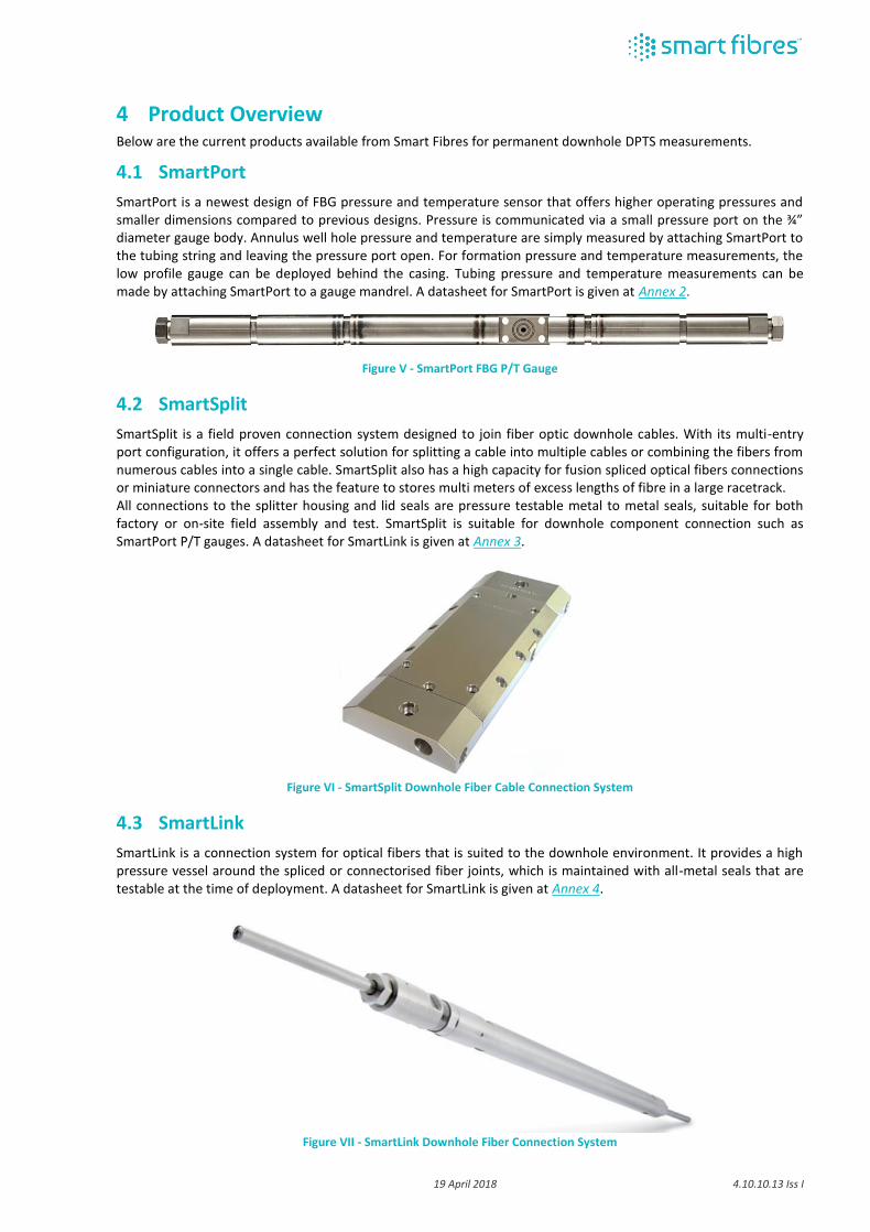
SmartPort is a newest design of FBG pressure and temperature sensor that offers higher operating pressures and smaller dimensions compared to previous designs. Pressure is communicated via a small pressure port on the ¾” diameter gauge body. Annulus well hole pressure and temperature are simply measured by attaching SmartPort to the tubing string and leaving the pressure port open. For formation pressure and temperature measurements, the low profile gauge can be deployed behind the casing. Tubing pressure and temperature measurements can be made by attaching SmartPort to a gauge mandrel. A datasheet for SmartPort is given at Annex 2.
Figure V - SmartPort FBG P/T Gauge
4.2 SmartSplit
SmartSplit is a field proven connection system designed to join fiber optic downhole cables. With its multi-entry port configuration, it offers a perfect solution for splitting a cable into multiple cables or combining the fibers from numerous cables into a single cable. SmartSplit also has a high capacity for fusion spliced optical fibers connections or miniature connectors and has the feature to stores multi meters of excess lengths of fibre in a large racetrack. All connections to the splitter housing and lid seals are pressure testable metal to metal seals, suitable for both factory or on-site field assembly and test. SmartSplit is suitable for downhole component connection such as SmartPort P/T gauges. A datasheet for SmartLink is given at Annex 3.
Figure VI - SmartSplit Downhole Fiber Cable Connection System
4.3 SmartLink
SmartLink is a connection system for optical fibers that is suited to the downhole environment. It provides a high pressure vessel around the spliced or connectorised fiber joints, which is maintained with all-metal seals that are testable at the time of deployment. A datasheet for SmartLink is given at Annex 4.
Figure VII - SmartLink Downhole Fiber Connection System

19 April 2018 4.10.10.13 Iss I
4.4 Gauge Clamps
Various designs of clamps are available to attach SmartPort products to tubing strings or tailpipes of different diameters. For simple installations, low cost steel bands or a pressed steel clamp assembly can be used. For more challenging installations in, for example, horizontal or deviated wells, then a more robust cast clamp is available. For applications where tubing pressure measurements are required, various forms of single or dual SmartPort gauge mandrels are available.
Figure VIII - Various gauge clamps; Left – pressed steel protector on 3.5” production tubing; Middle – dual SmartPort on gauge mandrel; Right – cast machined protector
4.5 Downhole Cable
The downhole cable comprises a fiber in metal tube (FIMT) construction and connects each deployed sensor to the topside instrumentation. With the use of multiplexing, the number of fibers required is significantly lower than the number of connected sensors. Typically, the fibers are deployed in ¼” outer diameter metal tube with gel filling and polymer encapsulation suited to the well conditions. Example datasheets of standard and high temperature downhole cable from a typical cable vendor can be downloaded from https://www.aflglobal.com/Products/Fiber-Optic-Cable/Downhole.aspx
Figure IX – Example downhole cable
4.6 Surface Pressure Barrier
Operators running DPTS and other fiber sensing techniques sometimes have concern as to whether well fluids may have opportunity to escape to surface through the inside of the FIMT in the case of a compromise of the tube integrity downhole. Whilst the FIMT offers a gel filling around the fibres which significantly reduces the likelihood of such a leak to surface, a surface pressure barrier SmartPB is offered to provide absolute certainty of well integrity. A datasheet for SmartPB is given at Annex 5.
Figure X – SmartPB surface pressure barrier

19 April 2018 4.10.10.13 Iss I
4.7 Wellhead SmartScope Topside Instrumentation
Topside instrumentation comprises a FBG interrogator and, as required, equipment for environmental protection, remote power supply and onward communications. The principal requirement of the FBG interrogator is to make precise wavelength measurements that maintain their stability over the long term, regardless of excursions in ambient temperature, and to offer sufficient dynamic range that this precision is maintained for relatively low signals returned from remote sensors.
Figure XI – Wellhead SmartScope FBG interrogator
The Wellhead SmartScope interrogator is the preferred instrument for this application. A datasheet for Wellhead SmartScope is given at Annex 6. Wellhead SmartScope can perform processing and data conversion using customisable firmware. In some cases, a further processing module is required for more advanced data conversion, processing and analysis. This processing module can be a PC platform or similar, rated to the requirements of the topside environment.
19 April 2018 4.10.10.13 Iss I
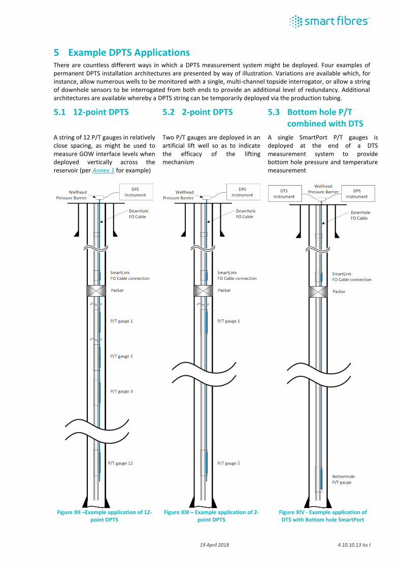
5 Example DPTS Applications There are countless different ways in which a DPTS measurement system might be deployed. Four examples of permanent DPTS installation architectures are presented by way of illustration. Variations are available which, for instance, allow numerous wells to be monitored with a single, multi-channel topside interrogator, or allow a string of downhole sensors to be interrogated from both ends to provide an additional level of redundancy. Additional architectures are available whereby a DPTS string can be temporarily deployed via the production tubing.
5.1 12-point DPTS
A string of 12 P/T gauges in relatively close spacing, as might be used to measure GOW interface levels when deployed vertically across the reservoir (per Annex 1 for example)
5.2 2-point DPTS
Two P/T gauges are deployed in an artificial lift well so as to indicate the efficacy of the lifting mechanism
5.3 Bottom hole P/T combined with DTS
A single SmartPort P/T gauges is deployed at the end of a DTS measurement system to provide bottom hole pressure and temperature measurement
Figure XII –Example application of 12-
point DPTS
Figure XIII – Example application of 2-
point DPTS
Figure XIV - Example application of DTS with Bottom hole SmartPort

19 April 2018 4.10.10.13 Iss I
5.4 4-point DPTS combined with DTS
4 P/T gauges are located in each of four zones of a horizontal producer. Together with a DTS system, the flow allocation and zonal isolation performance is monitored.
Figure XV - Example application of 4-point DPTS combined with DTS
19 April 2018 4.10.10.13 Iss I
Annex 1 – Project Reference. DPTS development and trial deployment,
PDO, Oman
(latest update available at https://www.smartfibres.com/files/pdf/ADIPEC.pdf)

HOST

SPE-188868-MS Development and Field Application
of a Permanent Fiberoptic Wellbore Fluid Level Monitoring System
Chris Staveley, Smart Fibres Ltd., United Kingdom
SPE-188868-MS • Development and Field Application of a Permanent Fiberoptic Wellbore Fluid Level Monitoring System • Chris Staveley
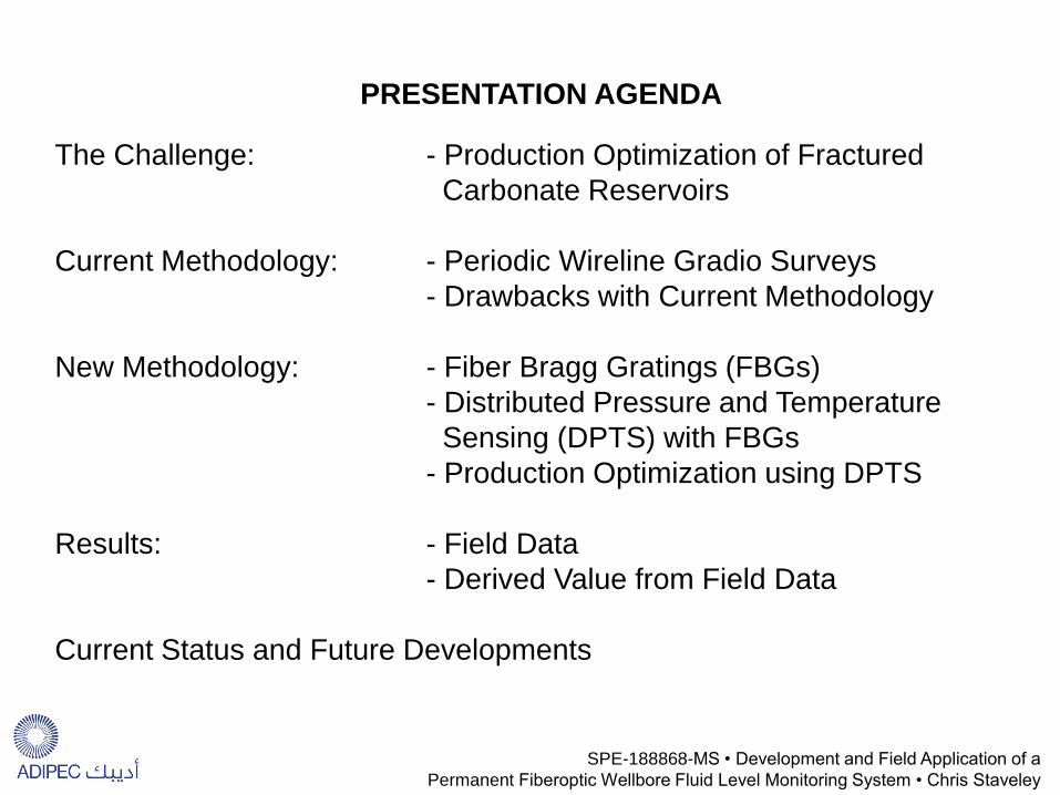
The Challenge: - Production Optimization of Fractured Carbonate Reservoirs Current Methodology: - Periodic Wireline Gradio Surveys - Drawbacks with Current Methodology New Methodology: - Fiber Bragg Gratings (FBGs) - Distributed Pressure and Temperature Sensing (DPTS) with FBGs - Production Optimization using DPTS Results: - Field Data - Derived Value from Field Data Current Status and Future Developments
PRESENTATION AGENDA
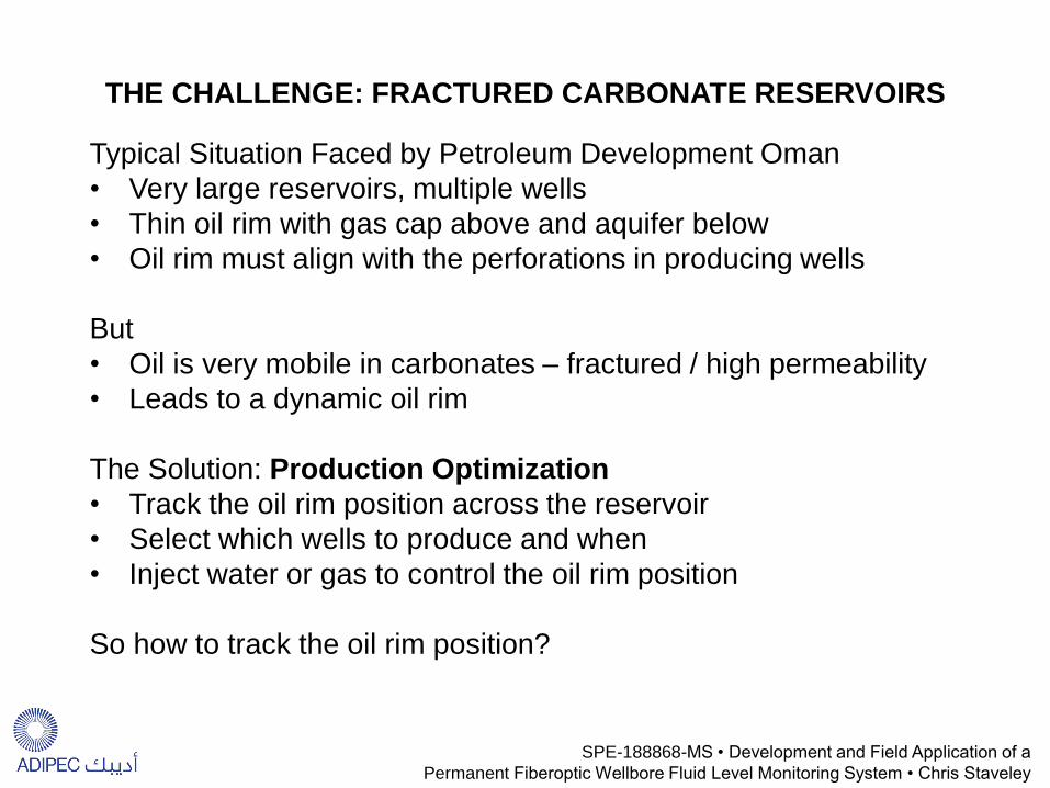
Typical Situation Faced by Petroleum Development Oman • Very large reservoirs, multiple wells • Thin oil rim with gas cap above and aquifer below • Oil rim must align with the perforations in producing wells But • Oil is very mobile in carbonates – fractured / high permeability • Leads to a dynamic oil rim The Solution: Production Optimization • Track the oil rim position across the reservoir • Select which wells to produce and when • Inject water or gas to control the oil rim position
So how to track the oil rim position?
THE CHALLENGE: FRACTURED CARBONATE RESERVOIRS
SPE-188868-MS • Development and Field Application of a Permanent Fiberoptic Wellbore Fluid Level Monitoring System • Chris Staveley
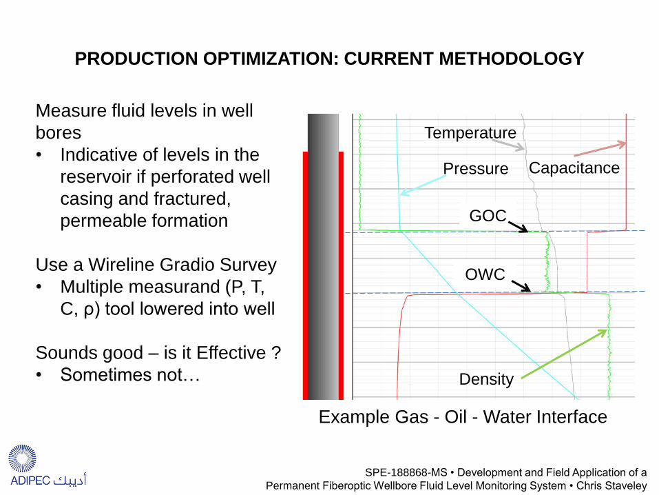
PRODUCTION OPTIMIZATION: CURRENT METHODOLOGY
Measure fluid levels in well bores • Indicative of levels in the
reservoir if perforated well casing and fractured, permeable formation
Use a Wireline Gradio Survey • Multiple measurand (P, T,
C, ρ) tool lowered into well Sounds good – is it Effective ? • Sometimes not…
GOC
OWC
Pressure
Density
Temperature
Capacitance
Example Gas - Oil - Water Interface
SPE-188868-MS • Development and Field Application of a Permanent Fiberoptic Wellbore Fluid Level Monitoring System • Chris Staveley

WIRELINE GRADIO SURVEY: DRAWBACKS
Data not real time • True dynamic information
missed… Data accuracy questionable • Differences between
repeated gradio runs “orders of magnitude
greater than the interpretation required” [1]
HSE Risks Involved • Each survey requires a
manned well intervention
[1] Shanks, David. April 2016. Digital Oilfield Monitoring Artificial Lift. SPE Webinar.
SPE-188868-MS • Development and Field Application of a Permanent Fiberoptic Wellbore Fluid Level Monitoring System • Chris Staveley
10 years of data suggest continuous oil rim

NEW METHODOLOGY: DISTRIBUTED PRESSURE SENSING WITH FIBER BRAGG GRATINGS
• A collaborative development project: • Shell Global Solutions – Project Initiators and Sponsor • Smart Fibres – Solution Developers • Petroleum Development Oman – Field trial hosts and first end user
• Project Timeline:
2004
2010
2015
2016
Project Start
System Development
Trial Deployments
System Optimisation
Commercialisation
SPE-188868-MS • Development and Field Application of a Permanent Fiberoptic Wellbore Fluid Level Monitoring System • Chris Staveley

FIBER BRAGG GRATINGS
Alternating bands of high and low refractive index
UV Laser Light
Single-mode Telecoms Optical Fibre
• A Fiberoptic Sensor • Recorded with UV laser light – changes core refractive index • Unique Bragg wavelength λΒ reflected according to the equation
• Bragg wavelength Varies with strain and temperature
Bragg Wavelength Change Strain Change Temperature Change
ΔλΒ = λΒ(1-ρα)Δε + λΒ(α+ξ)ΔT ΔλΒ = λΒ(1-ρα)Δε + λΒ(α+ξ)ΔT ΔλΒ = λΒ(1-ρα)Δε + λΒ(α+ξ)ΔT ΔλΒ = λΒ(1-ρα)Δε + λΒ(α+ξ)ΔT
SPE-188868-MS • Development and Field Application of a Permanent Fiberoptic Wellbore Fluid Level Monitoring System • Chris Staveley
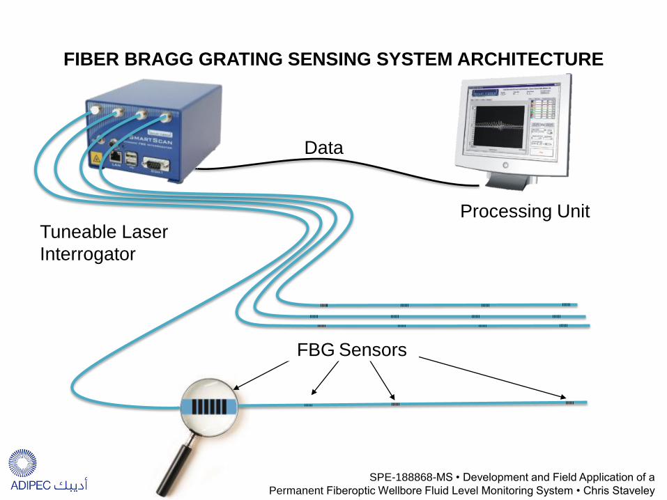
Tuneable Laser Interrogator
Processing Unit
FIBER BRAGG GRATING SENSING SYSTEM ARCHITECTURE
Data
SPE-188868-MS • Development and Field Application of a Permanent Fiberoptic Wellbore Fluid Level Monitoring System • Chris Staveley
FBG Sensors

PRESSURE / TEMPERATURE SENSING WITH FBGS
¼” Control Line
2 Single Mode Fibers
Wellbore Pressure
Sealed Vacuum
Pressure Cell
Pressure Diaphragm
FBG Attached to Pressure Diaphragm
¼” Control Line to
next Gauge
FBG Attached to Temperature Coupon
Pressure Input Port
Mandrel Seal (for tubing pressure)
¾” O.D. Gauge Assembly
Internal Diaphragm ¼” Control Line to
next Gauge ¼” Control
Line
SPE-188868-MS • Development and Field Application of a Permanent Fiberoptic Wellbore Fluid Level Monitoring System • Chris Staveley

Gas
O
il W
ater
Pressure
Dep
th
GOC
OWC
Pole Mounted Surface Instrument
PRODUCTION OPTIMIZATION USING DPTS
Dow
nhol
e P
T G
auge
s SPE-188868-MS • Development and Field Application of a
Permanent Fiberoptic Wellbore Fluid Level Monitoring System • Chris Staveley

1. Tested DPTS gauge array delivered to well site
2. Gauge array run over large diameter sheave
3. Gauges fixed to tubing string with steel clamps
4. Solar Powered Surface instrumentation radios P/T data to PDO server
5. Software on PDO server calculates fluid interfaces
DPTS SPOOLED DEPLOYMENT METHOD
SPE-188868-MS • Development and Field Application of a Permanent Fiberoptic Wellbore Fluid Level Monitoring System • Chris Staveley

DPTS PRESSURE FIELD DATA
• Showing pressure reported from 14 deployed gauges over 5 months • Very stable data (dP in gas phase ~1kPa = 0.15psi) • Relative gauge movement correlates with reported change of phase
SPE-188868-MS • Development and Field Application of a Permanent Fiberoptic Wellbore Fluid Level Monitoring System • Chris Staveley

DPTS FLUID CONTACTS FIELD DATA
Field Data from PDO Carbonate Reservoir, 2014/15 • Result from well with
15 Gauges deployed • 6 months of data
shown • Oil rim disappears
twice • Gradio method would
give 1 datapoint in this time window - i.e. it completely misses this behaviour
SPE-188868-MS • Development and Field Application of a Permanent Fiberoptic Wellbore Fluid Level Monitoring System • Chris Staveley
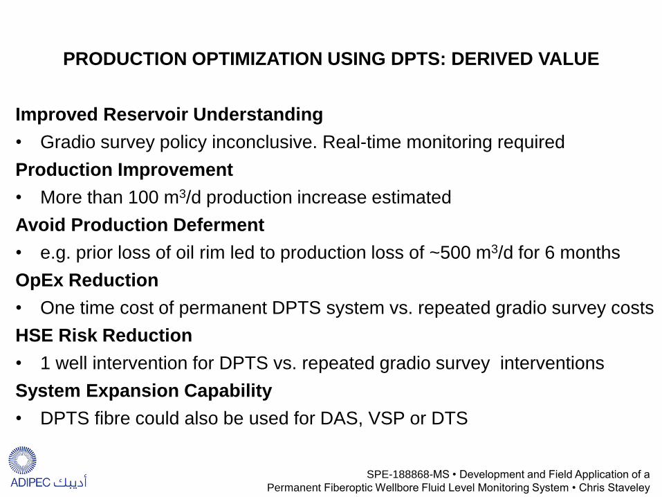
PRODUCTION OPTIMIZATION USING DPTS: DERIVED VALUE
Improved Reservoir Understanding
• Gradio survey policy inconclusive. Real-time monitoring required
Production Improvement
• More than 100 m3/d production increase estimated
Avoid Production Deferment
• e.g. prior loss of oil rim led to production loss of ~500 m3/d for 6 months
OpEx Reduction
• One time cost of permanent DPTS system vs. repeated gradio survey costs
HSE Risk Reduction
• 1 well intervention for DPTS vs. repeated gradio survey interventions
System Expansion Capability
• DPTS fibre could also be used for DAS, VSP or DTS
SPE-188868-MS • Development and Field Application of a Permanent Fiberoptic Wellbore Fluid Level Monitoring System • Chris Staveley
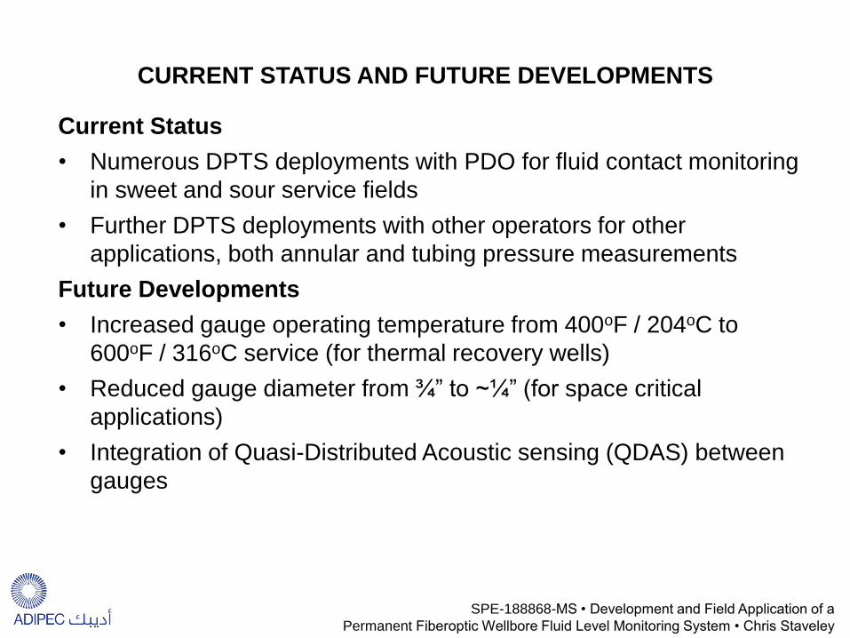
CURRENT STATUS AND FUTURE DEVELOPMENTS
Current Status
• Numerous DPTS deployments with PDO for fluid contact monitoring in sweet and sour service fields
• Further DPTS deployments with other operators for other applications, both annular and tubing pressure measurements
Future Developments
• Increased gauge operating temperature from 400oF / 204oC to 600oF / 316oC service (for thermal recovery wells)
• Reduced gauge diameter from ¾” to ~¼” (for space critical applications)
• Integration of Quasi-Distributed Acoustic sensing (QDAS) between gauges
SPE-188868-MS • Development and Field Application of a Permanent Fiberoptic Wellbore Fluid Level Monitoring System • Chris Staveley

Acknowledgements / Thank You / Questions
Thanks to the following co-authors: Crispin Doyle and Corne Coetzee, Smart Fibres
Andre Franzen, Hans den Boer, Arthur van Rooyen and William Birch, Shell
Ali Biderkab and Evert Moes, Petroleum Development Oman
Thanks for sponsoring the project and granting permission to publish to:
Shell Global Solutions International B.V. Petroleum Development Oman
Sultanate of Oman Ministry of Oil and Gas
SPE-188868-MS • Development and Field Application of a Permanent Fiberoptic Wellbore Fluid Level Monitoring System • Chris Staveley

19 April 2018 4.10.10.13 Iss I
Annex 2 – SmartPort datasheet
(latest update available at https://www.smartfibres.com/files/pdf/SmartPort.pdf)

SmartPort
Low Profile Fiber Optic P/T Gauge
5.001.316.08 +44 (0) 1344 484111 [email protected] smartfibres.com 1
SmartPort P/T Gauge
Key Features
HPHT Fibre Optic Gauge
No Downhole Electronics
All Metal Sealing
Long Life at Extreme Temperature
High Multi-Drop Capability
Annulus, Tubing or Ported Pressure Configurations
Low Profile ¾” Design
Low Cost
About SmartPort SmartPort is a low profile ¾” fibre optic P/T gauge. Pressure is communicated via a small pressure port on the gauge body to SmartPort’s novel internal optical sensing mechanism where pressure and temperature measurements are made using two fibre Bragg grating sensors. Annulus pressure and temperature are simply measured by leaving the pressure port open to the wellbore. For formation pressure and temperature measurements, the low profile gauge can be deployed open hole behind the casing. For tubing pressure and temperature measurements, SmartPort can be attached to a gauge mandrel with the use of dual metal o-ring or c-ring seals. Pressure from alternative locations can be communicated to SmartPort via a tube which seals to the gauge at the mandrel interface. Multiple SmartPorts can be multiplexed on a ¼” downhole cable to which the gauges are sealed using pressure testable swaged connections. Optical connection between SmartPort gauges is made using our ¾” SmartLink product. Up to 15 SmartPort gauges can be multiplexed on every 2 fibres. So, for instance, 30 gauges can be deployed using a 4 fibre main cable and one downhole ‘Y’ splitter. For HT and/or HP application with increased stability, an HPHT SmartPort is under development. Contact us for further details. Specifications
Measurement Pressure and Temperature of Annulus, Tubing or Ported Fluid
Working Pressure Range (psi / bar) 1,000/69 1,450/100 5,075/350 10,150/700 15,000/1,034 20,000/1,379*
Overload Pressure 150 %FS
Working Temperature Range 0 to 400 °F / -20 to 200 °C (>400 °F / 200 °C to follow)
Pressure Accuracy (psi / mbar)
< 0.1 %FS
1/69 1.5/100 5/350 10/700 15/1,034 20/1,379

SmartPort
Low Profile Fiber Optic P/T Gauge
5.001.316.08 +44 (0) 1344 484111 [email protected] smartfibres.com 2
Pressure Resolution at 0.1 Hz (psi / mbar)
< 0.005 %FS
0.05/3.4 0.07/5 0.25/17.5 0.5/35 0.75/52 1/69
Temperature Accuracy 0.2 °F / 0.1 °C
Pressure Measurement Drift
at 140 °F / 60 °C Immeasurable
at 260 °F / 125 °C 0.1 %FS/yr*
at 400 °F / 200 °C 0.5 %FS/yr*
Multi-Drop Capability Up to 24 gauges per 2 fibres
Wetted Parts Inconel
SmartPort Variant Sensor Type
Upper Connection
Lower Connection
Diameter in (mm)
Length in (mm)
Weight lb (kg)
SPPT In-line 2 fibre pigtails 2 fibre pigtails 0.75 (19) 15.7 (400) 1.48 (0.67)
SPPT1 In-line 2 fibre pigtails Splicing chamber 0.75 (19) 30.6 (778) 2.78 (1.26)
SPPT2 In-line Splicing chamber Splicing chamber 0.75 (19) 45.5 (1,156) 4.09 (1.86)
TSPPT Terminal 2 fibre pigtails None 0.75 (19) 10.8 (275) 0.98 (0.45)
TSPPT1 Terminal Splicing chamber None 0.75 (19) 25.7 (653) 2.29 (1.04)
¼” cable connection to previous SmartPort gauge ¼” cable connection to next SmartPort gauge
SPPT model pictured Pressure port with mandrel interface
*Expected performance, not yet verified
Specifications may change without notice

19 April 2018 4.10.10.13 Iss I
Annex 3 – SmartSplit datasheet
(latest update available at https://www.smartfibres.com/files/pdf/SmartSplit.pdf)
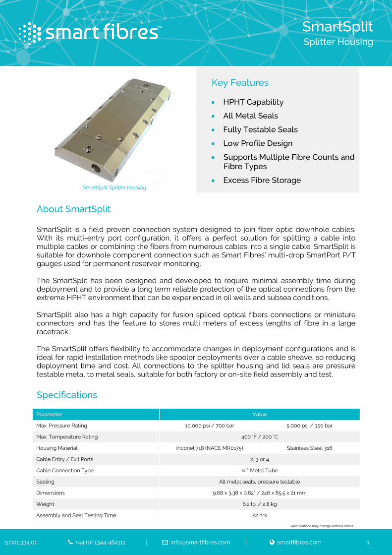
SmartSplit
Splitter Housing
5.001.334.01 +44 (0) 1344 484111 [email protected] smartfibres.com 1
SmartSplit Splitter Housing
Key Features
HPHT Capability
All Metal Seals
Fully Testable Seals
Low Profile Design
Supports Multiple Fibre Counts and Fibre Types
Excess Fibre Storage
About SmartSplit SmartSplit is a field proven connection system designed to join fiber optic downhole cables. With its multi-entry port configuration, it offers a perfect solution for splitting a cable into multiple cables or combining the fibers from numerous cables into a single cable. SmartSplit is suitable for downhole component connection such as Smart Fibres’ multi-drop SmartPort P/T gauges used for permanent reservoir monitoring. The SmartSplit has been designed and developed to require minimal assembly time during deployment and to provide a long term reliable protection of the optical connections from the extreme HPHT environment that can be experienced in oil wells and subsea conditions. SmartSplit also has a high capacity for fusion spliced optical fibers connections or miniature connectors and has the feature to stores multi meters of excess lengths of fibre in a large racetrack. The SmartSplit offers flexibility to accommodate changes in deployment configurations and is ideal for rapid installation methods like spooler deployments over a cable sheave, so reducing deployment time and cost. All connections to the splitter housing and lid seals are pressure testable metal to metal seals, suitable for both factory or on-site field assembly and test. Specifications Parameter Value
Max. Pressure Rating 10,000 psi / 700 bar 5,000 psi / 350 bar
Max. Temperature Rating 400 °F / 200 °C
Housing Material Inconel 718 (NACE MR0175) Stainless Steel 316
Cable Entry / Exit Ports 2, 3 or 4
Cable Connection Type ¼ “ Metal Tube
Sealing All metal seals, pressure testable
Dimensions 9.68 x 3.38 x 0.82“ / 246 x 85.5 x 21 mm
Weight 6.2 lb. / 2.8 kg
Assembly and Seal Testing Time ≤2 hrs
Specifications may change without notice

SmartSplit
Splitter Housing
5.001.334.01 +44 (0) 1344 484111 [email protected] smartfibres.com 2
Ordering Information
Product Type Housing Configuration Pressure Rating
S-Split - X - XX
I 5k
Y 10k
H
Order code example: S-Split-Y-10k Variant Description Variant Options Variant Code
Housing Configuration
1 Entry + 1 Exit port I
2 Entry + 1 Exit port
or 1 Entry + 2 Exit ports Y
2 Entry + 2 Exit ports H
Pressure Rating 5,000 psi (350 bar) 5k
10,000 psi (700 bar) 10k

19 April 2018 4.10.10.13 Iss I
Annex 4 – SmartLink datasheet
(latest update available at https://www.smartfibres.com/files/pdf/SmartLink.pdf)

SmartLink Rugged Connection System for Permanent Downhole Optical Sensors
5.001.501.04 +44 (0) 1344 484111 [email protected] smartfibres.com 1
Example SmartLink
Key Features
HPHT Capability
All Metal Sealing
Seals Fully Testable
Low Profile Design
About SmartLink Smart Fibres have developed a range of low-cost, downhole optical P/T gauges for permanent reservoir monitoring. Many tens of these gauges can be deployed in a well from a single main cable. In order to make such a multi-drop P/T deployment viable, an inter-sensor connection system is required which itself is low-cost, requires minimal rig time to deploy, and provides a long-term reliable protection of the optical connections from the extreme wellhole environment. The SmartLink system satisfies these requirements. Two SmartLink systems are available – using fusion splices or (in the case of low temperature applications) miniature connectors. The spliced SmartLink system allows a string of P/T gauges to be pre-assembled either in the factory or in a workshop container at the field. Then this string can be rapidly run in hole over a cable sheave, so minimising rig time. The connectorised SmartLink system offers increased flexibility to accommodate changes in deployment configurations. It employs miniature optical connectors that can be safely and quickly mated on the rig floor. Specifications
HPHT SmartLink Specifications
Parameter Spliced SmartLink
Max. Pressure Rating 15,000 psi / 1,000 bar
Max. Temperature Rating 400 °F / 200 °C
Materials Stainless, alloy or superalloy steel to suit application and well chemistry
Sealing All metal seals, pressure tested
Dimensions ¾ x 18.3″
Assembly and Seal Testing Time ~2 hrs
LPLT SmartLink Specifications (Preliminary)
Parameter Spliced SmartLink Connectorised SmartLink
Max. Pressure Rating 5,000 psi / 350 bar
Max. Temperature Rating 300 °F / 150 °C
Materials Stainless, alloy or superalloy steel to suit application and well chemistry
Sealing All metal seals, pressure tested
Dimensions ¾ x 18.3″ 1 x 19″
Assembly and Seal Testing Time ~2 hrs ~1 hr
Specifications may change without notice

19 April 2018 4.10.10.13 Iss I
Annex 5 – SmartPB Surface Pressure Barrier datasheet
(latest update available at https://www.smartfibres.com/files/pdf/SmartPB.pdf)

SmartPB
Surface Pressure Barrier
5.001.320.03 +44 (0) 1344 484111 [email protected] smartfibres.com 1
Key Features
Surface Pressure Barrier
Ensures Well Integrity for Downhole Optical Monitoring Installations
Supports Multiple Fibre Counts and Fibre Types
High Pressure Rating
A: Pressure Housing
B: Input Cable from Well
C: Output Fibres to Surface Instrument
D: Pressure Seal Around Fibres
About SmartPB A downhole optical sensing installation typically involves a multi-fibre cable which provides communication from the downhole gauges to the surface instrumentation. Such cable is normally of a fibre in metal tube (FIMT) construction, where the outer diameter is a ¼” steel tube. Sealing of this ¼” tube as it passes through downhole packers, tubing hangers and the like can be readily and reliably done using industry standard compression fittings. However, there sometimes remains a concern as to whether well fluids may have opportunity to escape to surface through the inside of the FIMT in the case of a compromise of the tube integrity downhole. Whilst the FIMT offers a gel filling around the fibres which significantly reduces the likelihood of such a leak to surface, SmartPB is offered as a surface pressure barrier to provide absolute certainty of well integrity. SmartPB comprises a pressure tight housing (A) within which spliced or connectorised joining of the fibres from the downhole cable (B) to the surface fibres (C) can be made. A pressure barrier (D) is made around the surface fibres so that, in the event that well fluids reach the surface through cable (B), they are contained within housing (A). Optionally, a pressure gauge is provided as a visual indication that the housing has been pressurised.
Specifications
Parameter Value
Dimensions 7.87 x 5.90 x 1.42“ / 200 x 150 x 36 mm
Weight 18.7 lb / 8.5 Kg
Housing Material SS 316
Sealing Material Fibre seal – Epoxy
Lid seal – Viton Cable seal – Metal to metal compression
Operating Temperature -40 to +85 °C / -40 to 185 °F
Rated Pressure 3,000 psi at 20 °C / 2,000 psi at 85 °C
Specifications may change without notice
A
D
C B

19 April 2018 4.10.10.13 Iss I
Annex 6 – Wellhead SmartScope FBG interrogator datasheet
(latest update available at https://www.smartfibres.com/files/pdf/Wellhead_SmartScope.pdf)
Wellhead SmartScope
FBG Interrogator
5.001.241.01 +44 (0) 1344 484111 [email protected] smartfibres.com 1
Wellhead SmartScope
Key Features
High Resolution FBG Interrogator
High Accuracy And Stability
Insensitive To Polarisation Effects
Low Power Consumption
On-board Data Processing
Solid State Light Source
Compact and Lightweight
Broad Operating Temperature
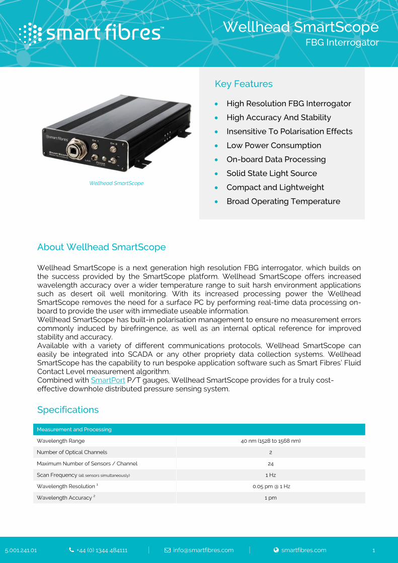
About Wellhead SmartScope Wellhead SmartScope is a next generation high resolution FBG interrogator, which builds on the success provided by the SmartScope platform. Wellhead SmartScope offers increased wavelength accuracy over a wider temperature range to suit harsh environment applications such as desert oil well monitoring. With its increased processing power the Wellhead SmartScope removes the need for a surface PC by performing real-time data processing on-board to provide the user with immediate useable information. Wellhead SmartScope has built-in polarisation management to ensure no measurement errors commonly induced by birefringence, as well as an internal optical reference for improved stability and accuracy. Available with a variety of different communications protocols, Wellhead SmartScope can easily be integrated into SCADA or any other propriety data collection systems. Wellhead SmartScope has the capability to run bespoke application software such as Smart Fibres’ Fluid Contact Level measurement algorithm. Combined with SmartPort P/T gauges, Wellhead SmartScope provides for a truly cost-effective downhole distributed pressure sensing system. Specifications Measurement and Processing
Wavelength Range 40 nm (1528 to 1568 nm)
Number of Optical Channels 2
Maximum Number of Sensors / Channel 24
Scan Frequency (all sensors simultaneously) 1 Hz
Wavelength Resolution 1 0.05 pm @ 1 Hz
Wavelength Accuracy 2 1 pm

Wellhead SmartScope
FBG Interrogator
5.001.241.01 +44 (0) 1344 484111 [email protected] smartfibres.com 2
Wavelength Stability over Operating Temperature Range 3 1 pm
Polarisation Extinction Ratio 4 < 1dB
Dynamic Range 5 38 dB
Gain Control 9 levels, per channel or per sensor, automatic or user controlled
FBG Full Width at Half Maximum (FWHM) > 0.2 nm, 0.5 nm recommended
Mechanical, Environmental and Electrical
Dimensions (W x H x D) 45 x 135 x 203 mm / 1.77 x 5.31 x 7.99”
Weight 2 kg / 4.4 lb.
Operating Temperature 6 -15 to +60 °C / 5 to 140 °F
Storage Temperature -40 to +85 °C / -40 to 185 °F
Comms Interface Ethernet/TCP-IP Modbus/TCP
Data Connector RJ45
Power Connection via mains adapter or DC cable supplied
Optical Connector FC/APC
Input Voltage +9 to +36 VDC
Power Consumption typ 8.5 W, max. 10 W
EMC Certification Per BS EN 61326-1 edition 2006
Hazardous Area Certification (optional) Per ATEX for hazardous zones 0, 1 or 2 with gas groups IIA, IIB or IIC Link to certification
1 Measurement distributions (1σ) when measuring a controlled artefact having recommended FWHM, during 16 hours. Maintained for up to 15 dB optical gain. 2 Per NIST Technical note 1297, maximum wavelength difference when compared to NIST SRM 2519. Measurement with instrument at 25 °C. 3 Per NIST Technical note 1297, ed 1994, D1.1.3 Maximum wavelength variations over full temperature range. The measurand is NIST SRM 2519.
4 Light is not polarised out of the instrument, therefore polarisation rotation cannot increase the measurement uncertainty. 5 Laser launch power minus detector noise floor. 6 +60 °C as standard, +70 °C in development.
Specifications may change without notice