with Authorised Submitted Schedule
78
Halspan Authorised Document Valid only when Submitted with Permission Schedule
Transcript of with Authorised Submitted Schedule

Halspa
n Auth
orise
d Doc
umen
t
Valid o
nly w
hen S
ubmitte
d with
Permiss
ion S
ched
ule

The legal validity of this report can only be claimed on presentation of the complete report.
Report for: Halspan Ltd Ref: FEA/F96103 Revision L Page 2 of 78
Contents
Page No
1 Introduction ................................................................................................................. 3
2 General Description of Construction ........................................................................... 3
3 Leaf Sizes................................................................................................................... 3
4 Configurations ............................................................................................................ 3
5 Leaf Size Adjustment .................................................................................................. 4
6 Overpanels ................................................................................................................. 4
7 Glazing ....................................................................................................................... 6
8 Door Frames ............................................................................................................ 11
9 Lipping Materials ...................................................................................................... 14
10 Edge Protectors ........................................................................................................ 15
11 Leaf Facing Materials ............................................................................................... 16
12 Intumescent Materials .............................................................................................. 19
13 Adhesives ................................................................................................................. 20
14 Tested Hardware ...................................................................................................... 20
15 Additional & Alternative Hardware ............................................................................ 21
16 Classification of Timber ............................................................................................ 26
17 Door Gaps ................................................................................................................ 26
18 Structural Opening .................................................................................................... 26
19 Fixings ...................................................................................................................... 26
20 Sealing to Structural Opening ................................................................................... 27
21 Insulation .................................................................................................................. 28
22 Smoke Control .......................................................................................................... 28
23 Conclusion................................................................................................................ 29
24 Declaration by the Applicant ..................................................................................... 30
25 Limitations ................................................................................................................ 31
26 Validity ...................................................................................................................... 31
Appendix A - Steel Frame Doorsets ................................................................................ 32
Appendix B - Glazing Systems ........................................................................................ 35
Appendix C - Test Evidence ............................................................................................ 39
Appendix D - Revisions ................................................................................................... 43
Appendix E - PVC Edge Protectors ................................................................................. 44
Appendix F - Data Sheets ............................................................................................... 45
Appendix G - Halspan Prima Plus Specification .............................................................. 68
Halspa
n Auth
orise
d Doc
umen
t
Valid o
nly w
hen S
ubmitte
d with
Permiss
ion S
ched
ule

The legal validity of this report can only be claimed on presentation of the complete report.
Report for: Halspan Ltd Ref: FEA/F96103 Revision L Page 3 of 78
1 Introduction
This document constitutes a global assessment relating to Halspan® 60 Prima, fire
resisting doorsets, for Halspan Ltd. The assessment uses established extrapolation and interpretation techniques in order to extend the scope of application by determining the limits for the design based on the tested constructions and performances obtained. The assessment is an evaluation of the potential fire resistance performance, if the elements were to be tested in accordance with BS 476: Part 22: 1987.
2 General Description of Construction
The construction for door leaves of this design comprises a solid sheet of 54mm thick
Halspan® 60 Prima three layered particleboard (nominal density 630kg/m³ +/- 10%).
Where specified, the leaves are lipped with hardwood.
3 Leaf Sizes
The approval for increased leaf dimensions is based on the tests listed in appendix C and takes into account the margin of over performance above 60 minutes integrity for the design and the characteristics exhibited during test. Data sheets specifying the maximum approved leaf sizes and graphs showing the permitted gradient between maximum height and width, are contained in appendix F.
Doorsets with reduced dimensions are deemed to be less onerous. Therefore, doors with dimensions that are less than those tested and stated in appendix F may be manufactured.
4 Configurations
Based on the test evidence listed in appendix C, this assessment covers the following doorset configurations:
Abbreviation Description
LSASD & ULSASD Latched & unlatched single acting single doorset
DASD Double acting single doorset
LSASD+OP & ULSASD+OP Latched & unlatched single acting single doorset + overpanel
DASD + OP Double acting single doorset + overpanel
LSADD & ULSADD Latched & unlatched single acting double doorset
DADD Double acting double doorset
LSADD+OP & ULSADD+OP Latched & unlatched single acting double doorset + overpanel
DADD + OP Double acting double doorset + overpanel
Unequal leaf double doorsets are covered by this assessment with no restriction on the smaller leaf dimension.
Halspa
n Auth
orise
d Doc
umen
t
Valid o
nly w
hen S
ubmitte
d with
Permiss
ion S
ched
ule

The legal validity of this report can only be claimed on presentation of the complete report.
Report for: Halspan Ltd Ref: FEA/F96103 Revision L Page 4 of 78
5 Leaf Size Adjustment
Halspan® 60 Prima door leaves may be altered as follows:
Element Reduction
Leaf The manufactured size of the leaf may be reduced in height or width without restriction
Lipping The dimensions stated in section 9.1 may be reduced by 20% for fitting purposes
6 Overpanels
6.1 Solid
Overpanels of the same construction as the door leaves may be used either flush with the leaf heads or when separated by a transom. In either case the overpanel must be fully contained within the door frame (see following diagram).
If a transom is required to separate the leaf heads from the overpanel, it must be to the same specification as the door frame (see the note under the table in section 8.1).
Door frame joints must utilise one of the following four methods: mortise and tenon joints; half lapped joints; mitre joints; butt joints (see section 8.2).
All methods require joints to be tight, with no gaps, and require mechanical fixing with the appropriate size ring shank nails or screws. Butt joints must be additionally bonded with urea formaldehyde or equivalent.
Overpanels must be fixed by either:
• screwing through the rear of the frame with steel screws passing at least 30mm into the centre line of the overpanel. Fixings must be no more than 100mm from each corner and a maximum of 250mm centres in between, or,
• using 75mm long x 8mm diameter steel dowels fitted centrally in the frame reveal across the head of the overpanel no closer than 150mm from each corner of the overpanel and equispaced between at a maximum of 450mm centres. A minimum of four dowels must be used. A further 75mm long screw fixing is required to be inserted at an angle through the bottom corners of the overpanel into the door frame.
The intumescent seals specified for the jambs in appendix F, may be fitted in the overpanel edges or frame reveal, if required for the manufacturing process. Providing the intumescent seals are fitted to all edges of the overpanel, the frame to overpanel junction is permitted to have a maximum 2mm gap tolerance.
However, it is not mandatory to fit intumescent seals to the edges of the overpanel for a compliant doorset providing the frame to overpanel junction is tight with no gaps.
It is permitted to include a glazed aperture within the overpanel providing the glazing is within the parameters given in section 7.
Maximum overpanel heights are as follows.
• Single doorsets – 2000mm
• Double doorsets – 1500mm
Halspa
n Auth
orise
d Doc
umen
t
Valid o
nly w
hen S
ubmitte
d with
Permiss
ion S
ched
ule

The legal validity of this report can only be claimed on presentation of the complete report.
Report for: Halspan Ltd Ref: FEA/F96103 Revision L Page 5 of 78
Note: Drawing is representative of doorset construction only, actual construction must be as the text within this document specifies
6.2 Fanlights
Timber frame doorsets including a transom may include a glazed fanlight. The timber frame and glazing beads must be hardwood with a minimum density of 640 kg/m3,
whilst the frame section must be a minimum of 70mm x 44mm. Timber door frame and transom construction must comply with the specification contained in section 8. The maximum assessed fanlight dimensions are detailed in the table below, subject to the following restriction:
• The glazing system and glass must be able to demonstrate adequate performance when tested as a window or screen in accordance with BS 476: Part 22: 1987 or BS EN 1634-1: 2000 or 2008, at the pane dimensions to be installed.
Configuration Height (mm) Width (mm)
Single & double doorsets ≤600 Overall door width
Overpanel fixings
Intumescent seals
Leaf head
Transom
Halspa
n Auth
orise
d Doc
umen
t
Valid o
nly w
hen S
ubmitte
d with
Permiss
ion S
ched
ule

The legal validity of this report can only be claimed on presentation of the complete report.
Report for: Halspan Ltd Ref: FEA/F96103 Revision L Page 6 of 78
Note: Drawing is representative of doorset construction only, actual construction must be as the text within this document specifies
7 Glazing
7.1 General
The testing conducted on Halspan® 60 Prima has demonstrated that the design is
capable of tolerating relatively large glazed apertures, whilst providing a margin of over performance. Glazing is therefore acceptable within the following parameters.
The maximum assessed glazed area for all configurations is 0.82m².
7.2 Assessed Glazing Systems
The glazing system must be one of the following proprietary tested systems:
Glazing System Manufacturer Maximum Area (m2)
1. Fireglaze 60 Sealmaster Ltd 0.82
2. Therm-A-Glaze 60 Intumescent Seals Ltd 0.82
3. System 36/15 Lorient Polyproducts Ltd 0.5
4. System 90+ Lorient Polyproducts Ltd 0.5
5. System 63 (circular apertures only)
Lorient Polyproducts Ltd 0.5
6. Pyroglaze 60 Mann McGowan Ltd 0.5
7. Halspan 60 Halspan Ltd 0.5
8. Halspan Slimglaze 60 Halspan Ltd 0.5
Assessed glass type
Glazing seal
Transom
Leaf head
Bead fixings
Halspa
n Auth
orise
d Doc
umen
t
Valid o
nly w
hen S
ubmitte
d with
Permiss
ion S
ched
ule

The legal validity of this report can only be claimed on presentation of the complete report.
Report for: Halspan Ltd Ref: FEA/F96103 Revision L Page 7 of 78
Notes:
1. Pyroglaze 60 and Halspan 60 must be used with 60mm long steel screw fixings only
2. Halspan Slimglaze 60 must be installed as depicted in appendix B
7.3 Assessed Glass Products
Assessed glass types are as follows:
Glass Type Manufacturer Maximum Area (m2)
1. 6 & 7mm Pyroshield Pilkington Group Ltd 0.82
2. 6 & 7mm Pyroshield 2 Pilkington Group Ltd See section 7.7
3. 6mm Sureglaze Wired Halspan Ltd 0.82
4. 6mm Pyran S Schott Glass Ltd 0.82
5. 6mm Pyrocet Securiglass Co. Ltd Limited by glazing system (see section 7.5 for approved glazing system)
6. 6mm Pyrostem CGI Ltd 0.60
7. 7mm Pyroguard FD60 CGI Ltd 0.82
8. 10mm Pyrodur Pilkington Group Ltd 0.82
9. 11mm Pyroguard CGI Ltd 0.52
10. 12mm Pyrobelite AGC Flat Glass Europe 0.82
11. 13mm Pyrodur Pilkington Group Ltd 0.82
12. 15mm Pyroguard EI 30 CGI Ltd 0.82
13. 16mm Contraflam Vetrotech Saint Gobain Ltd 0.82
14. 15mm Pyrostop Pilkington Group Ltd 0.82
15. 16mm Pyrobel AGC Flat Glass Europe 0.82
Notes:
1. All glass types must be fitted fully in accordance with the manufacturers’ tested details/installation requirements, particularly with respect to edge cover and expansion tolerances.
Halspa
n Auth
orise
d Doc
umen
t
Valid o
nly w
hen S
ubmitte
d with
Permiss
ion S
ched
ule
The legal validity of this report can only be claimed on presentation of the complete report.
Report for: Halspan Ltd Ref: FEA/F96103 Revision L Page 8 of 78
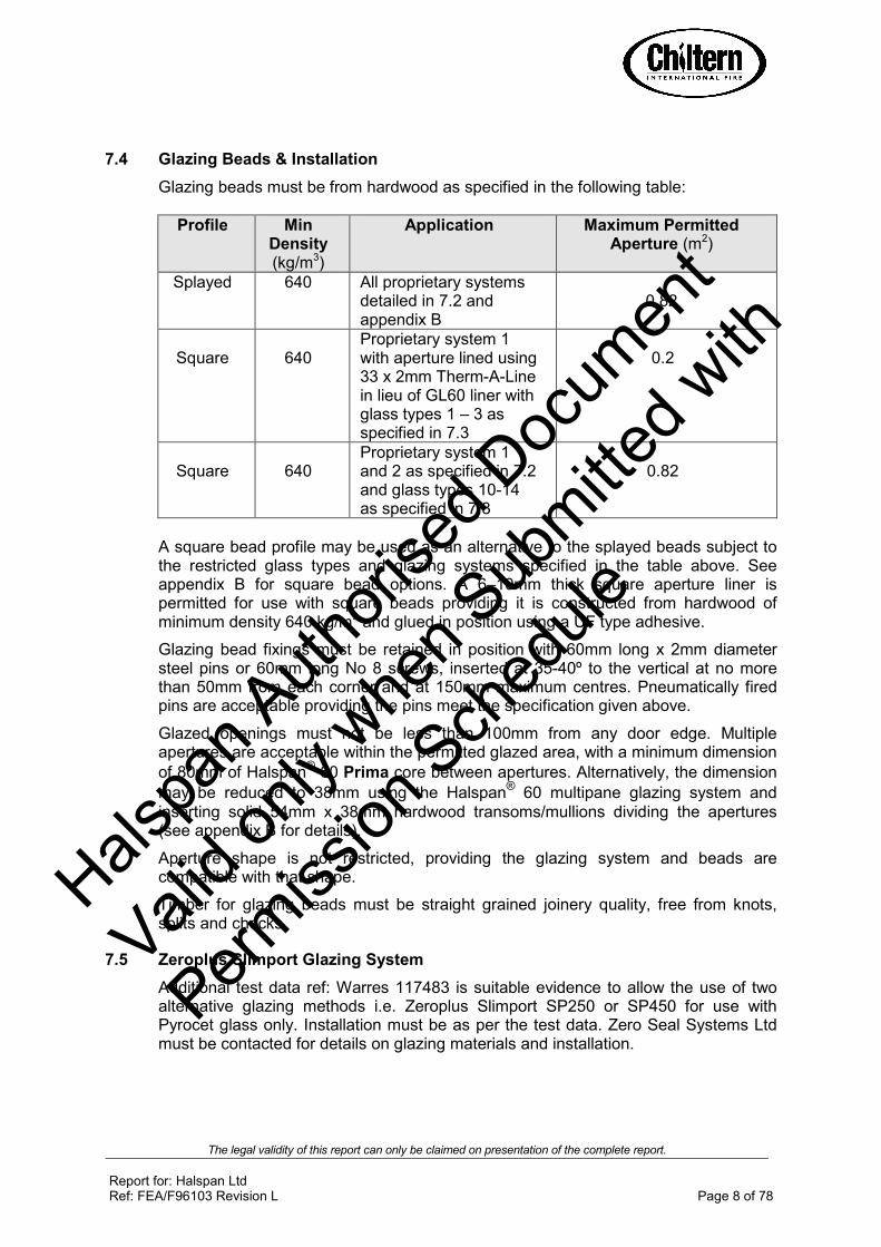
7.4 Glazing Beads & Installation
Glazing beads must be from hardwood as specified in the following table:
Profile Min Density (kg/m3)
Application Maximum Permitted Aperture (m2)
Splayed 640
All proprietary systems detailed in 7.2 and appendix B
0.82
Square
640
Proprietary system 1 with aperture lined using 33 x 2mm Therm-A-Line in lieu of GL60 liner with glass types 1 – 3 as specified in 7.3
0.2
Square
640
Proprietary system 1 and 2 as specified in 7.2 and glass types 10-14 as specified in 7.3
0.82
A square bead profile may be used as an alternative to the splayed beads subject to the restricted glass types and glazing systems specified in the table above. See appendix B for square bead options. A 6–10mm thick square aperture liner is permitted for use with square beads providing it is constructed from hardwood of minimum density 640 kg/m3 and glued in position using a UF type adhesive.
Glazing bead fixings must be retained in position with 60mm long x 2mm diameter steel pins or 60mm long No 8 screws, inserted at 35-40º to the vertical at no more than 50mm from each corner and at 150mm maximum centres. Pneumatically fired pins are acceptable providing the pins meet the specification given above.
Glazed openings must not be less than 100mm from any door edge. Multiple apertures are acceptable within the permitted glazed area, with a minimum dimension
of 80mm of Halspan® 60 Prima core between apertures. Alternatively, the dimension
may be reduced to 38mm using the Halspan® 60 multipane glazing system and
inserting solid 54mm x 38mm hardwood transoms/mullions dividing the apertures (see appendix B for details).
Aperture shape is not restricted, providing the glazing system and beads are compatible with that shape.
Timber for glazing beads must be straight grained joinery quality, free from knots, splits and checks.
7.5 Zeroplus Slimport Glazing System
Additional test data ref: Warres 117483 is suitable evidence to allow the use of two alternative glazing methods i.e. Zeroplus Slimport SP250 or SP450 for use with Pyrocet glass only. Installation must be as per the test data. Zero Seal Systems Ltd must be contacted for details on glazing materials and installation.
Halspa
n Auth
orise
d Doc
umen
t
Valid o
nly w
hen S
ubmitte
d with
Permiss
ion S
ched
ule

The legal validity of this report can only be claimed on presentation of the complete report.
Report for: Halspan Ltd Ref: FEA/F96103 Revision L Page 9 of 78
7.6 Fully Insulating Glazing Option
The testing conducted on Halspan® 60 Prima under ITB report No 636.7/09 has
demonstrated that the design is capable of providing 60 minutes integrity and insulation performance when glazed with 25mm thick Pyrobel glass from AGC Flat Glass Ltd. The option for fully insulating glazing is therefore acceptable within the following parameters.
The maximum assessed glazed area for all configurations is 1.31m². The glazing system must be one of the following tested proprietary systems (see appendix B for further details):
Glazing System Manufacturer Maximum Area (m2)
1. Fireglaze 60 Sealmaster Ltd 1.31
2. Therm-A-Glaze 60 Intumescent Seals Ltd 1.31
Notes:
1. The glass type is to be 25mm thick Pyrobel manufactured by AGC Flat Glass Ltd
2. A 6–10mm thick square aperture liner is permitted for use providing it is constructed from hardwood of minimum density 640 kg/m3 and glued in position using a PVA or UF type adhesive.
3. Glazing bead fixings must be retained in position with 70mm long No 8 screws, inserted at 30-35º to the vertical at no more than 50mm from each corner and at 150mm maximum centres.
4. Glazed openings must not be less than 100mm from any door edge. Multiple apertures are acceptable within the permitted glazed area, with a minimum
dimension of 80mm of Halspan® 60 Prima core between apertures.
5. Aperture shape is not restricted, providing the glazing system and beads are compatible with that shape.
6. Timber for glazing beads must be straight grained joinery quality, free from knots, splits and checks.
7. The glass must be fitted fully in accordance with the manufacturers’ tested details/installation requirements, particularly with respect to edge cover and expansion tolerances.
8. The permitted bead shapes are shown below.
Chamfered Bead
20o Chamfer
Bolection return
Upstand
Halspa
n Auth
orise
d Doc
umen
t
Valid o
nly w
hen S
ubmitte
d with
Permiss
ion S
ched
ule

The legal validity of this report can only be claimed on presentation of the complete report.
Report for: Halspan Ltd Ref: FEA/F96103 Revision L Page 10 of 78
Square Bead
7.7 Pyroshield 2
The following table details the maximum pane sizes and approved glazing systems
permitted for Pyroshield 2 in the Halspan® 60 Prima doorset design.
Glass Type Glazing System
(section 7.2) Maximum Pane Size* (height x width – mm)
Maximum Area (m²)
Pyroshield 2 2 1300 x 550 0.715
4 1300 x 310 0.4
*The heights and widths listed are the maximum single dimension allowable for an individual pane utilising the relevant glazing system; maximum dimensions may not be increased even if the other dimension for the pane is reduced.
Glazed openings must not be less than 100mm from any door edge. Multiple apertures are acceptable up to the maximum approved area, with a minimum dimension of 80mm between apertures. The aperture shape is not restricted, providing the intumescent material and beads are proven to be compatible with that shape.
Glazing bead fixings must be retained in position with 60mm long x 2mm diameter steel pins or 60mm long No 6-8 screws, inserted at 35-40º to the vertical at no more than 50mm from each corner and at 150mm maximum centres. Pneumatically fired pins are acceptable providing they meet the specification given above.
Timber for glazing beads must be straight grained joinery quality, free from knots, splits and checks.
False timber beads must not be applied across the glass face without specific test evidence to justify the system used.
Sectional drawings detailing the tested and approved proprietary glazing systems are contained in appendix B.
25
5
5
Suited to glass thickness
Upstand
Bolection return
Halspa
n Auth
orise
d Doc
umen
t
Valid o
nly w
hen S
ubmitte
d with
Permiss
ion S
ched
ule

The legal validity of this report can only be claimed on presentation of the complete report.
Report for: Halspan Ltd Ref: FEA/F96103 Revision L Page 11 of 78
8 Door Frames
8.1 Door frame construction
Timber based door frames for Halspan® 60 Prima must be constructed to meet the
following specification (for steel door frame options see appendix A):
Material Minimum Section Size
(mm)
Min Density (kg/m3)
Permitted configuration
Max leaf dimensions
(mm)
Hardwood (for use with
reduced intumescent)
70 x 32** 640 LSASD, ULSASD &
DASD, LSADD, ULSADD &
DADD
See relevant
data sheet in appendix
F
Hardwood* 70 x 32 530 LSASD & ULSASD
2100 (h) x 900 (w)
Hardwood* 70 x 44 530 All All
Hardwood* 70 x 22 640 All All
MDF* 70 x 30 700 All 2440 (h) and not
restricted in width
*Not permitted for use with reduced intumescent specification
**If the doorset features a transomed overpanel, the door frame must be hardwood with a minimum density of 640kg/m3 and with a minimum section of 70mm x 32mm.
All door frame timber must meet or exceed class J30 as specified in BS EN 942: 2007 (subject to adequate repair of any defects).
A 12mm deep planted or integral stop is adequate for single acting frames whilst double acting frames may be scalloped or square (see diagram below). However, a 14mm deep stop is required when using the Dorma ITS 96 concealed closer mounted in the leaf head – see section 14 for details.
Frame joints may be mortice and tenoned, mitred, half lapped or butted and with no gaps. All jointing methods require mechanical fixing with the appropriate size ring shank nails or screws.
Hinge fixings must be fit for purpose and if they penetrate through the rear of the frame, a sub frame of the same hardwood will be required. The entire screw length must be within a timber substrate.
The door frame (MDF or timber based) may be entirely clad in 2mm thick PVC sheeting for use with leaves either with or without 2mm thick PVC edge protectors (see section 10) and facing material (see section 11).
Halspa
n Auth
orise
d Doc
umen
t
Valid o
nly w
hen S
ubmitte
d with
Permiss
ion S
ched
ule

The legal validity of this report can only be claimed on presentation of the complete report.
Report for: Halspan Ltd Ref: FEA/F96103 Revision L Page 12 of 78
The following diagram depicts the assessed frame profiles and dimensions:
8.2 Door Frame Joints
Half Lapped Joint Mitre Joint
A = min 70mm B = min 22 - 44mm (see table above) C = min 12mm R = radius from floor spring 8mm max radius to create a maximum 2mm edge profiling
Standard Scalloped Profiled edges
Halspa
n Auth
orise
d Doc
umen
t
Valid o
nly w
hen S
ubmitte
d with
Permiss
ion S
ched
ule

The legal validity of this report can only be claimed on presentation of the complete report.
Report for: Halspan Ltd Ref: FEA/F96103 Revision L Page 13 of 78
Mortice and Tenon Joint Butt Joint
Note: Drawing is representative of each type of door frame joint, actual construction in terms of intumescent seal location and material etc. must be as the text within this document specifies
8.3 Door frame installation
The following diagrams indicate acceptable and unacceptable door frame installations.
6 to 10mm
Max 10 x 10mm shadow gap with 2mm
intumescent mastic capping or
10 x 4mm PVC encased intumescent seal
15mm
Permitted Permitted
PermittedNot PermittedNot Permitted
Permitted
Note: Drawing is representative of door frame installation, actual installation must be as the text within this document specifies. See section 20 for specification on sealing to structural opening.
Halspa
n Auth
orise
d Doc
umen
t
Valid o
nly w
hen S
ubmitte
d with
Permiss
ion S
ched
ule

The legal validity of this report can only be claimed on presentation of the complete report.
Report for: Halspan Ltd Ref: FEA/F96103 Revision L Page 14 of 78
9 Lipping Materials
9.1 Timber Lippings
Halspan® 60 Prima must be lipped in accordance with the following specification. The
lipping specifications for steel frame doorsets are contained in appendix A.
Material Size (mm) Min Density (kg/m3)
Straight grained, joinery quality hardwood, free from knots, splits and checks.
1. Flat = 6 – 18 thick with a maximum of 2mm profiling permitted at corners of lipping (see section 8.1)
2. Rounded = 8 – 18 thick with a radius matching the distance between leaf edge and floor pivot (see section 8.1)
3. Rebated = 20 – 30 thick with a 13mm deep equal rebate
640
Notes:
1. Overpanels separated from the leaf heads with a transom do not need to be lipped.
2. Overpanels flush with the leaf heads must be lipped on their bottom edge but may additionally be lipped on all edges if required.
3. Single and double doorsets without overpanels only require lipping on the vertical edges but may be additionally lipped on the top and bottom edges if required.
4. Leaves to doorsets with flush overpanels must be lipped on the vertical edges and additionally at the bottom edge of the overpanel and top edge of the doors.
5. Double doorsets without flush overpanels may use square or rebated meeting edges.
6. Double doorsets with flush overpanels may use a rebated overpanel junction and rebated meeting edge junction concurrently.
7. A 2.50 chamfer is permitted to the lipping at the leading edge of leaves providing the door gaps meet the requirements of section 17.
9.2 PVC Lippings
Halspan® 60 Prima may be lipped with PVC in accordance with the following
specification.
Material Size (mm) Min Density (kg/m3)
PVC 2 thick -
Halspa
n Auth
orise
d Doc
umen
t
Valid o
nly w
hen S
ubmitte
d with
Permiss
ion S
ched
ule

The legal validity of this report can only be claimed on presentation of the complete report.
Report for: Halspan Ltd Ref: FEA/F96103 Revision L Page 15 of 78
Notes:
1. Can be fitted direct to Halspan® 60 Prima core or onto hardwood lippings
as per section 9.1
9.3 ‘T’ Section Lippings
In certain circumstances, a ‘T’ section lipping may be required which will be bonded into a groove machined in the edge of the leaf. This option is acceptable providing the tongue is a maximum of 38mm wide and otherwise meets the specification given in section 9.1. The ‘T’ section lipping may be in two sections with the exposed lipping being within the range of 6 – 10mm thick. All glue lines must be as stated in section 13. See drawings below:
10 Edge Protectors
Fire resistance test RF02083 justifies the use of PVC 2mm thick edge protectors reference ‘Type 1, 2, 3, and 4’ (see appendix E for sketch details) on the vertical edges of the door leaves. The minimum intumescent specification given in appendix F must be maintained and the relevant glue lines specified in section 13 must be used. The edge protectors are suitable for use with leaves installed within both timber based and steel based frames. The PVC protectors may be used on double and single leaf doorsets alike.
The performances obtained and the leaf sizes tested in RF02083, when using the PVC edge protectors, will enable the use of these edge protectors on limited door leaf dimensions albeit on all configurations assessed in this report. The maximum leaf dimensions (whichever is the smaller between the appendix graphs and the table below) are therefore as follows:
Doorset Maximum height and width
configuration Type 1 and 3 Type 2 and 4
Single leaf doorsets 2090mm high x 853mm wide
2212 high x 902 wide
Double leaf doorsets 2040mm high x 828mm wide
2162 high x 877 wide
Halspa
n Auth
orise
d Doc
umen
t
Valid o
nly w
hen S
ubmitte
d with
Permiss
ion S
ched
ule
The legal validity of this report can only be claimed on presentation of the complete report.
Report for: Halspan Ltd Ref: FEA/F96103 Revision L Page 16 of 78
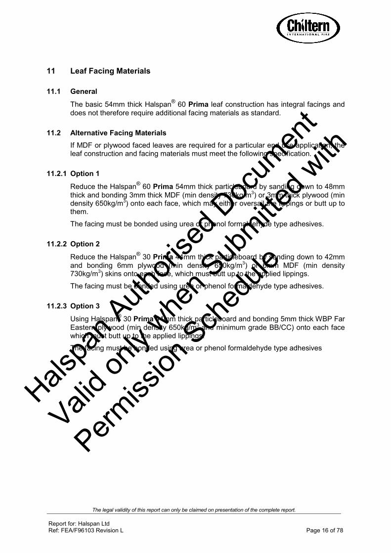
11 Leaf Facing Materials
11.1 General
The basic 54mm thick Halspan® 60 Prima leaf construction has integral facings and
does not therefore require additional facing materials as standard.
11.2 Alternative Facing Materials
If MDF or plywood faced leaves are required for a particular end use application, the leaf construction and facing materials must meet the following specification.
11.2.1 Option 1
Reduce the Halspan® 60 Prima 54mm thick particleboard by sanding down to 48mm
thick and bonding 3mm thick MDF (min density 730kg/m3) or 3mm thick plywood (min density 650kg/m3) onto each face, which may either oversail the lippings or butt up to them.
The facing must be bonded using urea or phenol formaldehyde type adhesives.
11.2.2 Option 2
Reduce the Halspan® 30 Prima 44mm thick particleboard by sanding down to 42mm
and bonding 6mm plywood (min density 650kg/m3) or 6mm MDF (min density 730kg/m3) skins onto each face, which must butt up to the applied lippings.
The facing must be bonded using urea or phenol formaldehyde type adhesives.
11.2.3 Option 3
Using Halspan® 30 Prima 44mm thick particleboard and bonding 5mm thick WBP Far
Eastern plywood (min density 650kg/m3 and minimum grade BB/CC) onto each face which must butt up to the applied lippings.
The facing must be bonded using urea or phenol formaldehyde type adhesives
Halspa
n Auth
orise
d Doc
umen
t
Valid o
nly w
hen S
ubmitte
d with
Permiss
ion S
ched
ule

The legal validity of this report can only be claimed on presentation of the complete report.
Report for: Halspan Ltd Ref: FEA/F96103 Revision L Page 17 of 78
11.3 Grooves
Both sides of Halspan® 60 Prima door leaves may be grooved to the following
specification. Grooves may coincide with the top and bottom of glazed apertures if desired:
11.3.1 Option A
Element Details
Max groove size (mm) 5 wide x 4 deep
Proximity to door edges (mm) Horizontal Grooves
≥ 150 from top and bottom
Vertical Grooves ≥ 150 from sides
Groove spacing (mm) Max 6 no grooves divided between horizontal and vertical orientations as required
Orientation Vertical or horizontal
Configuration Latched and unlatched, single and double acting, single and double leaf doorsets
Leaf size range (mm) All
Intumescent seal dimensions (mm) All
11.3.2 Option B
Element Details
Max groove size (mm) 15mm wide x 8mm deep in filled with hardwood timber (min 640kg/m3). The hardwood insert can be machined with a decorative 4mm deep x 5mm wide groove or a 4mm deep ‘V’ groove
Adhesive The hardwood insert must be tightly fitted and glued on all edges using a PVA adhesive
Proximity to door edges (mm) Horizontal Grooves
≥ 150 from top and bottom
Vertical Grooves ≥ 150 from sides
Groove spacing (mm) Max 8 no grooves divided between horizontal and vertical orientations as required and spaced minimum 150mm apart
Orientation Vertical or horizontal
Configuration Latched and unlatched, single and double acting, single and double leaf doorsets
Leaf size range (mm) All
Intumescent seal dimensions (mm) All
Halspa
n Auth
orise
d Doc
umen
t
Valid o
nly w
hen S
ubmitte
d with
Permiss
ion S
ched
ule

The legal validity of this report can only be claimed on presentation of the complete report.
Report for: Halspan Ltd Ref: FEA/F96103 Revision L Page 18 of 78
11.4 Decorative and Protective Facings
The following facing materials are permitted for this door design since they would degrade rapidly under test conditions without significant effect:
Notes:
1. Metallic facings are not permitted except for push plates and kick plates (see section 15.6)
2. The door leaf thickness may be reduced by a total maximum of 0.5mm for calibration purposes in order to accommodate the chosen finish
3. Other than PVC, materials must not return around leaf edges
4. Materials must not conceal intumescent strips
5. The PVC may be post-formed over the vertical and horizontal edges provided that the required intumescent specification detailed in appendix F is maintained. The maximum radius at the corners of the leaf for post formed doors is 8mm, see diagram in section 8.1 for details.
Facing Material Maximum Permitted Thickness (mm)
Paint 0.5
Timber veneers 2
Plastic laminates 2
PVC 2
Decorative paper / non-metallic foil 0.4
Halspa
n Auth
orise
d Doc
umen
t
Valid o
nly w
hen S
ubmitte
d with
Permiss
ion S
ched
ule

The legal validity of this report can only be claimed on presentation of the complete report.
Report for: Halspan Ltd Ref: FEA/F96103 Revision L Page 19 of 78
12 Intumescent Materials
Intumescent products can often exhibit significantly different characteristics, which could alter the performances obtained during test, and therefore they must not be considered interchangeable, irrespective of whether the product has been tested and the seal dimensions maintained. The intumescent materials tested and assessed for this doorset design are as follows:
Application Location Product/Manufacturer
Edge seals Fitted in the frame jambs or
leaf edges
1. PVC encased Therm-A-Seal – Intumescent Seals Ltd
2. PVC encased Type SLS – Halspan Ltd
3. PVC encased 500P – Mann McGowan Ltd
4. PVC encased Palsuol 100 – Lorient Polyproducts Ltd/Mann McGowan Ltd
5. PVC encased Type 617 – Lorient Polyproducts Ltd
6. PVC encased Pyroplex – Pyroplex Ltd
Hinges Underneath both hinge
blades
1. 1mm Interdens - Dufaylite Developments Ltd
2. 1mm MAP paper - Lorient Polyproducts Ltd
3. 1mm Pyrostrip 300 - Mann McGowan
4. 1mm Therm-A-Strip - Intumescent Seals Ltd
5. 1mm SLS-PAD-106 – Halspan Ltd
Lock/latches Under forend & keep
1. 1mm Interdens - Dufaylite Developments Ltd
2. 1mm MAP paper - Lorient Polyproducts Ltd
3. 1mm Pyrostrip 300 - Mann McGowan
4. 1mm Therm-A-Strip - Intumescent Seals Ltd
5. 1mm SLS-PAD-106 – Halspan Ltd
Top pivots & flush bolts
Lining all sides of the mortices
1. 2mm Interdens - Dufaylite Developments Ltd
2. 2mm MAP paper - Lorient Polyproducts Ltd
3. 2mm Therm-A-Strip - Intumescent Seals Ltd
4. 2mm Therm-A-Flex - Intumescent Seals Ltd
5. 1mm SLS-PAD-107 – Halspan Ltd
The seal specification for each configuration is contained in appendix F
Halspa
n Auth
orise
d Doc
umen
t
Valid o
nly w
hen S
ubmitte
d with
Permiss
ion S
ched
ule

The legal validity of this report can only be claimed on presentation of the complete report.
Report for: Halspan Ltd Ref: FEA/F96103 Revision L Page 20 of 78
13 Adhesives
The following adhesives must be used in construction:
Element Product/Manufacturer
MDF or Plywood facings Urea formaldehyde (UF) Phenol Formaldehyde (PF)
Timber lippings UF, PF, PVA, PVAC or PU
PVC lippings Contact adhesive
14 Tested Hardware
The following hardware has been successfully incorporated in the tests on Halspan®
60 Prima doorsets:
Element Manufacturer and Product Reference
Hinges 1. 100 x 30mm standard steel butt hinges 2. 101 x 30mm Fireblock stainless steel hinges 3. Royde & Tucker H105 lift off hinges 4. Royde & Tucker H101 lift off hinges 5. Cairney Hardware SOSS type hinges 6. 114 x 30mm ASSA lift off type butt hinge ref: 3244 7. 101 x 30mm Halspan R60 butt hinge ref: BOM-HIN-200/1
Closers 1. Dorma TS83 face fixed overhead closer 2. Geze TS200 VW face fixed overhead closer 3. Halspan R60 Eco closer ref: CLR-AGN-101 4. Halspan R60 power closer ref: CLR-BSS-101 5. Cairney Hardware Ltd Mitron C2300 concealed overhead
closer 6. ITS 96 concealed overhead closer with tested proprietary
intumescent system 7. Briton BTS75V floorsprings
Locks/latches 1. Standard tubular mortice latch 2. Firco multi point lock/latch 3. Halspan R60 latch/lock ref: BOM-LCK-104 4. Cairney Architectural Hardware Solutions – C4100 Shearmag
lock
Threshold seals
1. Halspan threshold drop seal ref: SAC PA 08935 ref: SLS-DRP-100 range
2. Norseal threshold drop seal ref: 810
Halspa
n Auth
orise
d Doc
umen
t
Valid o
nly w
hen S
ubmitte
d with
Permiss
ion S
ched
ule

The legal validity of this report can only be claimed on presentation of the complete report.
Report for: Halspan Ltd Ref: FEA/F96103 Revision L Page 21 of 78
Notes:
1. The GU Ferco 3 Deadbolt requires a 25 x 4mm thick intumescent strip in the closing edge frame reveal in lieu of the specification shown in appendix F and can only be used on single leaf doorsets of maximum leaf height 2231mm, and must be used in a hardwood (640kg/m3) door frame.
2. The Cairney Hardware Shearmag lock must be used in conjunction with a twin strip perimeter intumescent specification at the head of the door in conjunction with the Halspan intumescent protection pack fitted around the body of the lock
3. The Cairney Hardware Mitron C2300 concealed overhead closer must be used in conjunction with a twin strip perimeter intumescent specification at the head of the door in conjunction with the Halspan intumescent protection pack fitted around the body of the closer
4. The Dorma ITS 96 concealed overhead closer may be used with a single strip perimeter intumescent specification providing the strip is = to or > 25 x 4mm and centrally fitted. The closer may also be used with a twin strip perimeter intumescent specification at the head of the door providing the seals are = to or > than 15 x 4mm. The closer must always be used in conjunction with the proprietary intumescent pack to be provided by the supplier of the closer. The door stop will need to be a minimum depth of 14mm to accommodate the closer.
5. Locksets with forends/keeps = to or >than 150mm high must either be used with a twin strip perimeter intumescent specification or if a single strip system is to be used an additional seal must be fitted to run along side the forend/keep.
15 Additional & Alternative Hardware
15.1 Latches & Locks
Latches and locks must either be as tested, or alternatively components with the following specification are acceptable:
Element Specification
Maximum forend and strike plate dimensions:
235mm high by 25mm wide by 4mm thick
Maximum body dimensions:
18mm thick by 100mm wide by 165mm high.
Intumescent protection: See section 12
Materials: All parts essential to the locking/latching action (including the latch bolt, forend and strike) to be steel
Halspa
n Auth
orise
d Doc
umen
t
Valid o
nly w
hen S
ubmitte
d with
Permiss
ion S
ched
ule

The legal validity of this report can only be claimed on presentation of the complete report.
Report for: Halspan Ltd Ref: FEA/F96103 Revision L Page 22 of 78
15.2 Hinges
Leaves <2400mm (h) must be hung on 3 hinges. Leaves >2400mm (h) must be hung on 4 hinges. Hinges with the following specification are acceptable:
Element Specification
Blade height: 90 - 120mm
Blade width (excluding knuckle):
30 - 35mm
Blade thickness 2.5 - 4mm
Fixings: Minimum of 4 No. 30mm long No. 8 or No.10 steel wood screws per blade
Materials: Steel or stainless steel
Hinge positions:
If 3 hinges are required:
Top 100 –180mm from the head to top of hinge
2nd Minimum 200mm from top hinge or centrally fitted between top and bottom hinge
Bottom 150 - 250mm from the foot of leaf to bottom of hinge
If 4 hinges are required:
Top 100-180mm from the head to top of hinge
2nd & 3rd Equispaced between top and bottom or 2nd hinge 200mm from top hinge and 3rd hinge equally spaced between 2nd and bottom hinge
Bottom 150 - 250mm from the foot of leaf to bottom of hinge
Intumescent protection: See section 12
15.3 Automatic Closing
Automatic closing devices, must either be as tested or components of equal specification that have demonstrated contribution to the required integrity performance of this type of doorset design, when tested to BS 476: Part 22: 1987 or BS EN 1634-1: 2000 or 2008. Note: The top pivots to floorspring assemblies must be protected with 2mm thick intumescent gasket (see section 12) or alternatively the manufacturers tested intumescent pack.
Halspa
n Auth
orise
d Doc
umen
t
Valid o
nly w
hen S
ubmitte
d with
Permiss
ion S
ched
ule

The legal validity of this report can only be claimed on presentation of the complete report.
Report for: Halspan Ltd Ref: FEA/F96103 Revision L Page 23 of 78
15.4 Flush Bolts
Flush bolts may be incorporated centrally into the top and bottom of one meeting edge, providing the following maximum dimensions are not exceeded and the components are fitted opposite the edge fitted with intumescent strips:
• 200mm long x 20mm deep x 20mm wide.
Flush bolts must be steel and the mortice must be as tight to the mechanism as is compatible with its operation. All edges of the mortice must be protected with intumescent gaskets as specified in section 12. Alternatively the hardware manufacturers tested gaskets may be used.
15.5 Pull Handles
Handles may be surface-fixed or bolted through the door leaf, providing they are steel or brass and the length is limited to 1200 mm between the fixing points. If through fixed, there must be no more than 1mm clearance between the hole and stud.
15.6 Push Plates & Kick Plates
Face-fixed hardware such as push plates and kick plates may be fitted to the doorsets and may be recessed to a maximum depth of 2mm on both sides of the door leaf. These items of hardware are permitted up to a maximum of 20% of the door leaf area if mechanically fixed and a maximum of 30% if bonded with a contact or other thermally softening adhesive. Plates must not return around the door edges.
15.7 Panic Hardware
Panic hardware may be fitted, providing the installation does not require the removal of any timber from the leaf, stop or frame reveal and it does not interfere with the self-closing action of the door leaf.
Flush bolt mechanism
Intumescent gaskets
Door leaf
Halspa
n Auth
orise
d Doc
umen
t
Valid o
nly w
hen S
ubmitte
d with
Permiss
ion S
ched
ule

The legal validity of this report can only be claimed on presentation of the complete report.
Report for: Halspan Ltd Ref: FEA/F96103 Revision L Page 24 of 78
15.8 Door Selectors
Selectors may be fitted providing the installation does not require the removal of any timber from the leaf, stop or frame reveal and they do not interfere with the self-closing action of the door leaf.
15.9 Environmental Seals
Silicon based flame retardant acoustic, weather and dust seals (e.g. Halspan Triple Fin ref: SLS-TRI-100 range, Norseal 710, Lorient IS1212, IS1511, IS7025, IS7060) may be fitted to this doorset design with out compromising the performance, providing their fitting does not interfere with the activation of the intumescent seals or hinder the self closing function of the leaves.
15.10 Threshold Seals
The following types of automatic threshold drop seals may be recessed in to the bottom rail of leaves to this design with out compromising the performance:
• Halspan SLS-DRP-100 range
• Lorient Polyproducts IS8010si
• Raven RP8Si
• Athmer Schall-Ex Duo L-15
• Norseal 810
15.11 Letter Boxes/Plates
Letter boxes/plates may be fitted providing the product has demonstrated contribution to the required integrity performance of this type of doorset design, when tested to BS 476: Part 22: 1987 or BS EN 1634-1: 2000 or 2008, when installed in a timber based doorset of comparable thickness. Products may be fitted up to 1200mm from floor level and no closer than 100mm to any leaf edge.
15.12 Air Transfer Grilles
15.12.1 General
Air transfer grilles may be fitted providing the product has suitable test evidence to BS 476: Part 22: 1987 or BS EN 1634-1: 2000 or 2008 that demonstrates a minimum 60 minutes integrity performance when installed within a timber based doorset of comparable thickness. Margins to the leaf edges will remain as detailed for glazing and the position of the unit will be dictated by the pressure regime tested in the proving evidence (normally below mid height). The area occupied by the air transfer grille must not exceed that proven by the supporting fire test for the specific type of grille being used, and must be deducted from the area of glazing, if both elements are fitted.
Halspa
n Auth
orise
d Doc
umen
t
Valid o
nly w
hen S
ubmitte
d with
Permiss
ion S
ched
ule

The legal validity of this report can only be claimed on presentation of the complete report.
Report for: Halspan Ltd Ref: FEA/F96103 Revision L Page 25 of 78
15.12.2 Pyroplex Air Transfer Grilles
Based on the available test evidence the following Pyroplex air transfer grilles have
been considered acceptable for use with the Halspan® 60 Prima design.
The grilles must be fitted 100mm from the edge of the door leaf and 80mm apart if more than one grille is to be fitted. The area occupied by the air transfer grille must be deducted from the area of glazing, if both elements are fitted. The grilles may be fitted up to a maximum height of 2200mm from the threshold unless otherwise stated.
Part No. Dimensions (mm) Air Flow (sq. cm) Compatible Faceplates
ATG 1500 150 x 150 153 FP1500
ATG 1503 150 x 300 307 FP1503
ATG 1300 300 x 300 614 FP1300
ATG 2251* 112 x 225 161 FP2251
ATG 2250* 225 x 225 323 FP2250
*ATG 2251 and ATG 2250 must only be used above 1000mm height from the threshold of the door
The Pyroplex air transfer grilles must be installed in accordance with the manufacturer’s installation details, which include a 6mm thick hardwood aperture liner and Pyroplex intumescent mastic applied around the perimeter of the grille. Full details can be obtained from Pyroplex Ltd.
15.13 Cable-Way
Based on the integrity performance of the doorset construction, with no burn through of the core material, we consider it acceptable to allow the provision for a concealed cable-way to facilitate electro-magnetic closing/latching mechanisms. The cable-way must be concealed in the following way:
1. A hole drilled centrally through the leaf of maximum 10mm diameter.
2. The cable for the electronic closing/latching mechanisms must be no more than 2mm smaller in diameter than the hole through the leaf.
3. The cable for the electronic closing/latching mechanism must be PVC encased
4. Cable ways are only permitted for use with latched, single leaf, single acting doorsets with maximum leaf dimensions of 2100mm (h) x 900mm (w).
5. The hole must be located below 1500mm from the threshold and must be spaced a minimum of 90mm from any apertures within the leaf e.g glazing, air transfer grilles or letter plates etc.
This approval is subject to the hardware manufacturer having the appropriate test evidence for the product for use with this type of 60 minute construction. Test evidence generated in steel doorsets is not acceptable. Any tested intumescent gaskets for the lockset, closing mechanism, receiver plate, cable loops etc. must be replicated.
Halspa
n Auth
orise
d Doc
umen
t
Valid o
nly w
hen S
ubmitte
d with
Permiss
ion S
ched
ule

The legal validity of this report can only be claimed on presentation of the complete report.
Report for: Halspan Ltd Ref: FEA/F96103 Revision L Page 26 of 78
15.14 Security Viewers
Door security viewers with brass or steel bodies of a diameter less than or equal to 15mm may be used provided that the through-hole is bored tight to the case of the viewer (maximum tolerance +1 mm). Lenses must be glass and the item must be protected with a tested acrylic intumescent mastic.
16 Classification of Timber
All timber must meet or exceed class J30 as specified in BS EN 942: 2007, providing any defects are adequately repaired.
17 Door Gaps
Door gaps and alignment tolerances must fall within the following range:
Location Dimension
Door edge gaps Representative of those tested but as a guideline, a minimum of 2mm and a maximum of 4mm
Alignment tolerances Leaves must not be proud of each other or from the door frame by more than 1mm.
Threshold 10mm between bottom of leaf and top of floor covering
18 Structural Opening
The supporting construction must provide the required level of fire resistance designated for the doorset design and be a suitable medium to permit adequate fixity.
19 Fixings
The frame jambs are to be fixed to the supporting construction using steel fixings at 600mm maximum centres. The fixings must be of the appropriate type for the supporting construction and must penetrate to a minimum depth of 40mm. It is not necessary to fix the frame head, although packers must be inserted.
Halspa
n Auth
orise
d Doc
umen
t
Valid o
nly w
hen S
ubmitte
d with
Permiss
ion S
ched
ule

The legal validity of this report can only be claimed on presentation of the complete report.
Report for: Halspan Ltd Ref: FEA/F96103 Revision L Page 27 of 78
20 Sealing to Structural Opening
The door frame to structural opening gap must be protected using one of the following methods:
1. Gaps up to 10mm must be sealed on both sides with a 10mm depth of acrylic intumescent mastic, fire tested for this application to BS 476: Part 22: 1987 or BS EN 1634-1: 2000 or 2008. Joint must be fitted with 15mm thick architraves overlapping at least 15mm each side.
2. Gaps between 10mm and 20mm must be tightly packed with mineral fibre capped on both sides with a 10mm depth of acrylic intumescent mastic, fire tested for this application to BS 476: Part 22: 1987 or BS EN 1634-1: 2000 or 2008. Architraves are optional.
3. Gaps up to 20mm filled with proprietary fire stopping product (e.g. expanding PU foam or preformed compressible intumescent foam). Products must be tested for this application to BS 476: Part 22: 1987 or BS EN 1634-1: 2000 or 2008. Joint must be fitted with 15mm thick architraves overlapping at least 15mm each side.
4. Timber based or non-combustible subframe up to 50mm thick, with no gaps between the components. Joint must be fitted with 15mm thick architraves overlapping at least 15mm each side.
Fire stopping product
Frame fixing Architrave
Timber based or non-combustible subframe
Architrave
Fixing for subframe
Frame fixing
Architrave for joints not filled with mineral wool and optional for filled joints
Frame fixing
Mineral fibre infill for joints exceeding 10mm
Acrylic intumescent mastic
Halspa
n Auth
orise
d Doc
umen
t
Valid o
nly w
hen S
ubmitte
d with
Permiss
ion S
ched
ule
The legal validity of this report can only be claimed on presentation of the complete report.
Report for: Halspan Ltd Ref: FEA/F96103 Revision L Page 28 of 78
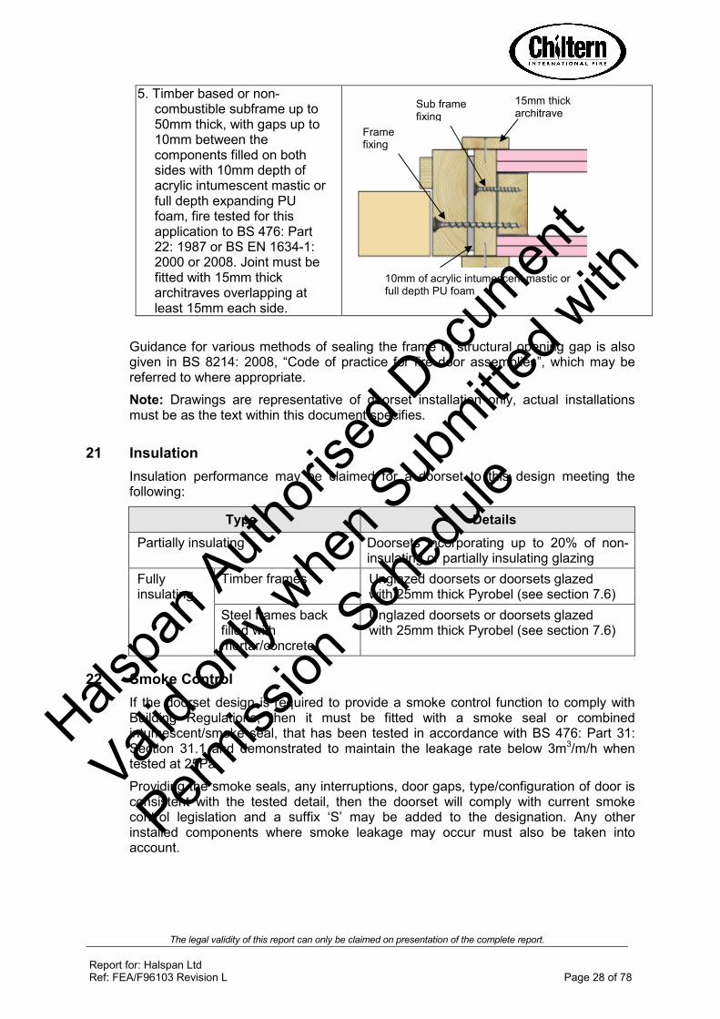
5. Timber based or non-combustible subframe up to 50mm thick, with gaps up to 10mm between the components filled on both sides with 10mm depth of acrylic intumescent mastic or full depth expanding PU foam, fire tested for this application to BS 476: Part 22: 1987 or BS EN 1634-1: 2000 or 2008. Joint must be fitted with 15mm thick architraves overlapping at least 15mm each side.
Guidance for various methods of sealing the frame to structural opening gap is also given in BS 8214: 2008, “Code of practice for fire door assemblies”, which may be referred to where appropriate.
Note: Drawings are representative of doorset installation only, actual installations must be as the text within this document specifies.
21 Insulation
Insulation performance may be claimed for a doorset to this design meeting the following:
Type Details
Partially insulating Doorsets incorporating up to 20% of non-insulating or partially insulating glazing
Fully insulating
Timber frames Unglazed doorsets or doorsets glazed with 25mm thick Pyrobel (see section 7.6)
Steel frames back filled with mortar/concrete
Unglazed doorsets or doorsets glazed with 25mm thick Pyrobel (see section 7.6)
22 Smoke Control
If the doorset design is required to provide a smoke control function to comply with Building Regulations, then it must be fitted with a smoke seal or combined intumescent/smoke seal, that has been tested in accordance with BS 476: Part 31: Section 31.1 and demonstrated to maintain the leakage rate below 3m3/m/h when tested at 25Pa.
Providing the smoke seals, any interruptions, door gaps, type/configuration of door is consistent with the tested detail, then the doorset will comply with current smoke control legislation and a suffix ‘S’ may be added to the designation. Any other installed components where smoke leakage may occur must also be taken into account.
15mm thick architrave architrave
10mm of acrylic intumescent mastic or full depth PU foam
Frame fixing
Sub frame fixing
Halspa
n Auth
orise
d Doc
umen
t
Valid o
nly w
hen S
ubmitte
d with
Permiss
ion S
ched
ule

The legal validity of this report can only be claimed on presentation of the complete report.
Report for: Halspan Ltd Ref: FEA/F96103 Revision L Page 29 of 78
Additional guidance on smoke sealing is given in BS 8214: 2008, “Code of practice for fire door assemblies” and BS 9999: 2008 “Code of practice for fire safety in the design, management and use of buildings” both of which advise that for effective ambient smoke sealing the threshold gap should either be controlled to a maximum of 3mm or a suitably fire performance tested threshold drop down seal fitted (eg one of the types described in section 15.10 or below)
The following Halspan products can be used for smoke control purposes:
• Halspan Triple Fin (ref: SLS-TRI-100/2) – fitted in the frame reveal against the upstand of the stop
• Halspan Trident Seal (ref: SLS-TRI-103/5)
• Halspan threshold drop seal (ref: SLS-DRP-100 range) – fitted in the bottom edge of the leaf
• Norseal 810 drop seal – fitted in the bottom edge of the leaf
• Norseal 710 perimeter seal – fitted in the frame reveal against the upstand of the doorstop
• Norseal 720 perimeter seal – fitted in the leaf edge or frame reveal
Note: The incorrect specification and fitting of smoke seals may impair the operation of a fire resisting doorset assembly such that integrity is reduced, or in the extreme case completely diminished.
23 Conclusion
If Halspan® 60 Prima doorset design, constructed in accordance with the
specification documented in this global assessment, were to be tested in accordance with BS 476 : Part 22 : 1987, it is our opinion that they would provide a minimum of 60 minutes integrity and insulation (subject to section 21).
Halspa
n Auth
orise
d Doc
umen
t
Valid o
nly w
hen S
ubmitte
d with
Permiss
ion S
ched
ule

The legal validity of this report can only be claimed on presentation of the complete report.
Report for: Halspan Ltd Ref: FEA/F96103 Revision L Page 30 of 78
24 Declaration by the Applicant
1. We the undersigned confirm that we have read and comply with obligations placed on us by FTSG Resolution No 82: 2001.
2. We confirm that the component or element of structure, which is the subject of this assessment, has not to our knowledge been subjected to a fire test to the Standard against which this assessment is being made.
3. We agree to withdraw this assessment from circulation should the component or element of structure be the subject of a fire test to the Standard against which this assessment is being made.
4. We are not aware of any information that could adversely affect the conclusions of this assessment.
5. If we subsequently become aware of any such information we agree to ask the assessing authority to withdraw the assessment.
Signed
Name:
For and on behalf of Halspan Ltd
Halspa
n Auth
orise
d Doc
umen
t
Valid o
nly w
hen S
ubmitte
d with
Permiss
ion S
ched
ule

Halspa
n Auth
orise
d Doc
umen
t
Valid o
nly w
hen S
ubmitte
d with
Permiss
ion S
ched
ule

The legal validity of this report can only be claimed on presentation of the complete report.
Report for: Halspan Ltd Ref: FEA/F96103 Revision L Page 32 of 78
Appendix A Halspan
® 60 Prima Steel Frame Doorsets
1. Introduction
This appendix contains information relating to Halspan® 60 Prima doorsets utilising
steel door frames. The assessment uses the same extrapolation and interpretation techniques applied for the main assessment and is an evaluation of the potential fire resistance performance, if the elements were to be tested in accordance with BS 476: Part 22: 1987.
2. General specification of construction
The door leaves for Halspan® 60 Prima steel framed doorsets are manufactured in
accordance with the design as specified in section 2 of FEA/F96103 Revision L. All other aspects of the construction specification are identical to that detailed in the main assessment except where specifically discussed in the following paragraphs.
3. Leaf sizes and configurations
The assessed leaf sizes and configurations are based on the constructions and performances obtained from the specimens tested in Warres 111201, RF01073 and RF01074. Data sheets specifying the maximum approved leaf sizes and graphs detailing the permitted gradient between height and width are contained in appendix F.
The maximum assessed overpanel height for steel framed doorsets is 500mm. Doorsets must use a flush overpanel to leaf head junction. Steel transomed assemblies are not permitted.
4. Lippings
Steel framed Halspan® 60 Prima must be lipped on all edges in accordance with the
following specification:
Material Size (mm) Min Density (kg/m3)
Straight grained, joinery quality hardwood, free from knots, splits and checks.
1. Flat = 6 – 13 thick with a maximum of 2mm profiling permitted at corners of lipping (see section 8.1)
2. Rounded = 6 – 13 thick with a radius matching the distance between leaf edge and floor pivot (see section 8.1)
640
Hals
pan A
uthori
sed D
ocum
ent
Valid o
nly w
hen S
ubmitte
d with
Permiss
ion S
ched
ule

The legal validity of this report can only be claimed on presentation of the complete report.
Report for: Halspan Ltd Ref: FEA/F96103 Revision L Page 33 of 78
5. Door frames
The tested frame specification for doorsets to this design comprised the following:
• Material: 1.5mm thick rolled mild steel
• Section: 151mm wide x 62mm thick excluding a 13mm deep x 48mm wide integral stop
• Head to jamb jointing detail
The door frames must be manufactured from mild steel as tested or alternatively stainless steel of the appropriate grade e.g. 304 or 316 may be used. The frame dimensions may be varied within the following parameters:
Z
Y
X
X: + or - 30% Y: + or - 50% (providing the frame reveal dimensions are maintained)
Z: + 100 % and −−−− 0%
The frame may be hollow or back filled with mortar or concrete.
Plasterboard, mineral fibre, glass fibre, polyurethane expanding foam and ceramic wool must not be used.
Appendix F details the different leaf size scopes and intumescent specifications for hollow and backfilled frame constructions.
6. Fixings
Fixings must be of the appropriate type and length for the structural opening medium and must include a minimum of 1 fixing per 600mm of vertical edge, with a fixing no more than 350mm from the top and bottom corners and two across the head.
7. Sealing to Structural Opening
Gaps between door frames and structural openings must be protected with proprietary materials that have been successfully tested for this application.
Halspa
n Auth
orise
d Doc
umen
t
Valid o
nly w
hen S
ubmitte
d with
Permiss
ion S
ched
ule

The legal validity of this report can only be claimed on presentation of the complete report.
Report for: Halspan Ltd Ref: FEA/F96103 Revision L Page 34 of 78
8. Structural openings
Halspan® 60 Prima steel framed doorsets may be fitted into the following types of
structural opening:
• Cast dense concrete
• Dense concrete blocks or brickwork
• Masonry
• Lightweight concrete
• Lightweight aerated concrete
• Timber stud partition
• Steel stud partition (apertures must be framed by steel studs, which have a minimum of 45 x 45mm softwood stiffeners to the vertical edges)
Halspa
n Auth
orise
d Doc
umen
t
Valid o
nly w
hen S
ubmitte
d with
Permiss
ion S
ched
ule

The legal validity of this report can only be claimed on presentation of the complete report.
Report for: Halspan Ltd Ref: FEA/F96103 Revision L Page 35 of 78
Appendix B 60 Minute Glazing Systems
516 25
60mm
pins or screws
60mm
pins or screws
60mm
pins or screws
Assessed glass
Assessed glass
Assessed glass
LX Palusol liner
2mm
LX Palusol liner
2mm
G60 liner5
16 25
flexible gasketSystem 36/15
45°25
17
Therm-A-Glaze 60
Intumescent Seals Ltd
System 36/15
Lorient Polyproducts Ltd
System 63
Lorient Polyproducts Ltd
Fireglaze Mastic
Sealmaster Ltd
60mm
pins or screws
2mm Therm-A-Line
Therm-A-Bead
Intumescent liner
20°
Assessed glass
555
555
25
25
25mm x 4 mm
4mmFireglaze mastic
20°
flexible gasketSystem 63
45°
Hals
pan A
uthori
sed D
ocum
ent
Valid o
nly w
hen S
ubmitte
d with
Permiss
ion S
ched
ule

The legal validity of this report can only be claimed on presentation of the complete report.
Report for: Halspan Ltd Ref: FEA/F96103 Revision L Page 36 of 78
Assessed glass
60mm
pins or screws
60mm
pins or screws
Assessed glass Assessed glass
intumescent liner2mm Pyroglaze 300
25mm x 3 mm Halspan 60
20°
5
5
16 25
Halspan 60
Halspan Ltd
60mm
pins or screws
intumescent liner2mm Pyroglaze 300
25mm x 3 mm 500P or 500PSA
20°
5
5
16 25
System 90+
Lorient Polyproducts Ltd
Pyroglaze 60
Mann McGowan Ltd
LX Palusol liner
2mm
System 90+ channel
45° 19
22
60mm screws
60mm screws
Halspa
n Auth
orise
d Doc
umen
t
Valid o
nly w
hen S
ubmitte
d with
Permiss
ion S
ched
ule

The legal validity of this report can only be claimed on presentation of the complete report.
Report for: Halspan Ltd Ref: FEA/F96103 Revision L Page 37 of 78
Assessed Square Glazing Bead Profiles
(the following square bead profiled may be used as an alternative to the splayed beads
detailed above - refer to section 7 for glazing system and glass restrictions)
Halspan Slimglaze 60 System
25
To finish flush with the leaf face
3
3
25
5
5
Suited to glass thickness
25
To finish flush with the leaf face
2mm thick Therm-A-Line (ISL) lining the bead and the glazed aperture
Slimglaze 60 gasket
Halspa
n Auth
orise
d Doc
umen
t
Valid o
nly w
hen S
ubmitte
d with
Permiss
ion S
ched
ule

The legal validity of this report can only be claimed on presentation of the complete report.
Report for: Halspan Ltd Ref: FEA/F96103 Revision L Page 38 of 78
Halspan® 60 Multipane glazing system
intumescent liner2mm thick GL60
20°
5
16 25
Halspan 60
60mm
pins or screws
Assessed glassFireglaze Mastic
(4mm thick)
54mm thick
hardwood section
50mm
pins or screws
54mm thick x 38mm deep hardwood section
Halspa
n Auth
orise
d Doc
umen
t
Valid o
nly w
hen S
ubmitte
d with
Permiss
ion S
ched
ule
The legal validity of this report can only be claimed on presentation of the complete report.
Report for: Halspan Ltd Ref: FEA/F96103 Revision L Page 39 of 78
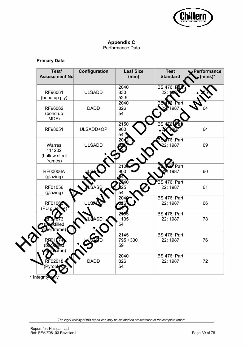
Appendix C Performance Data
Primary Data
Test/ Assessment No
Configuration Leaf Size (mm)
Test Standard
Performance (mins)*
RF96061
(bond up ply)
ULSADD
2040 830 52.5
BS 476: Part 22: 1987
55
RF96062 (bond up
MDF)
DADD
2040 826 54
BS 476: Part 22: 1987
64
RF98051
ULSADD+OP
2150 900 54
BS 476: Part 22: 1987
64
Warres 111202
(hollow steel frames)
ULSADD
2042 826 54
BS 476: Part 22: 1987
69
RF00006A (glazing)
ULSASD
2100 900 54
BS 476: Part 22: 1987
60
RF01056 (glazing)
ULSASD
2040 825 54
BS 476: Part 22: 1987
61
RF01065
(PU glueline)
ULSADD
2040 826 54
BS 476: Part 22: 1987
66
RF01073 (backfilled
steel frame)
ULSASD
2135 1105 54
BS 476: Part 22: 1987
78
RF01074 (backfilled
steel frame)
ULSADD
2145 795 +300 59
BS 476: Part 22: 1987
76
RF02018 (Pyroplex)
DADD
2040 826 54
BS 476: Part 22: 1987
72
* Integrity only
Halspa
n Auth
orise
d Doc
umen
t
Valid o
nly w
hen S
ubmitte
d with
Permiss
ion S
ched
ule

The legal validity of this report can only be claimed on presentation of the complete report.
Report for: Halspan Ltd Ref: FEA/F96103 Revision L Page 40 of 78
Test/ Assessment No
Configuration Leaf Size (mm)
Test Standard
Performance (mins)
RF02083
(Sureguard)
A: ULSADD
B: ULSADD
A & B: 2040 828/300 54
BS 476: Part 22: 1987
A = 60 B = 67
RF02125
(tall double doorsets,
MDF frames and 500P)
ULSADD + OP
2700 + 250 825 54
BS 476: Part 22: 1987
59
RF03041
ULSADD & ULSASD
A: 2135 826 + 300 54 B: 2135 915 54
BS 476: Part 22: 1987
A: 61
B: 61
RF04074
(bond up ply)
LSASD
2040 923 54
BS 476: Part
22: 1987
67
RF06005 A: ULSASD B: ULSASD
2125 915 54
BS 476: Part 22: 1987
A: 75 B: 75
RF07032 (Type 617
intumescent seals)
A: ULSADD
2040 827/303 54
BS 476: Part 22: 1987
71
B: ULSADD
2040 827/304 54
BS 476: Part 22: 1987
60
RF07128 (Type 617
and 100P and P.U foam fire
stopping detail)
A: ULSASD 2441 1236 54
BS 476: Part 22: 1987
72
B: ULSASD 2441 1236 54
BS 476: Part 22: 1987
67
RF08035 (Halspan
intumescent seals,
additional hardware – closer and
latch)
ULSADD 2054 910/413 54
BS 476: Part 22: 1987
64
Halspa
n Auth
orise
d Doc
umen
t
Valid o
nly w
hen S
ubmitte
d with
Permiss
ion S
ched
ule
The legal validity of this report can only be claimed on presentation of the complete report.
Report for: Halspan Ltd Ref: FEA/F96103 Revision L Page 41 of 78
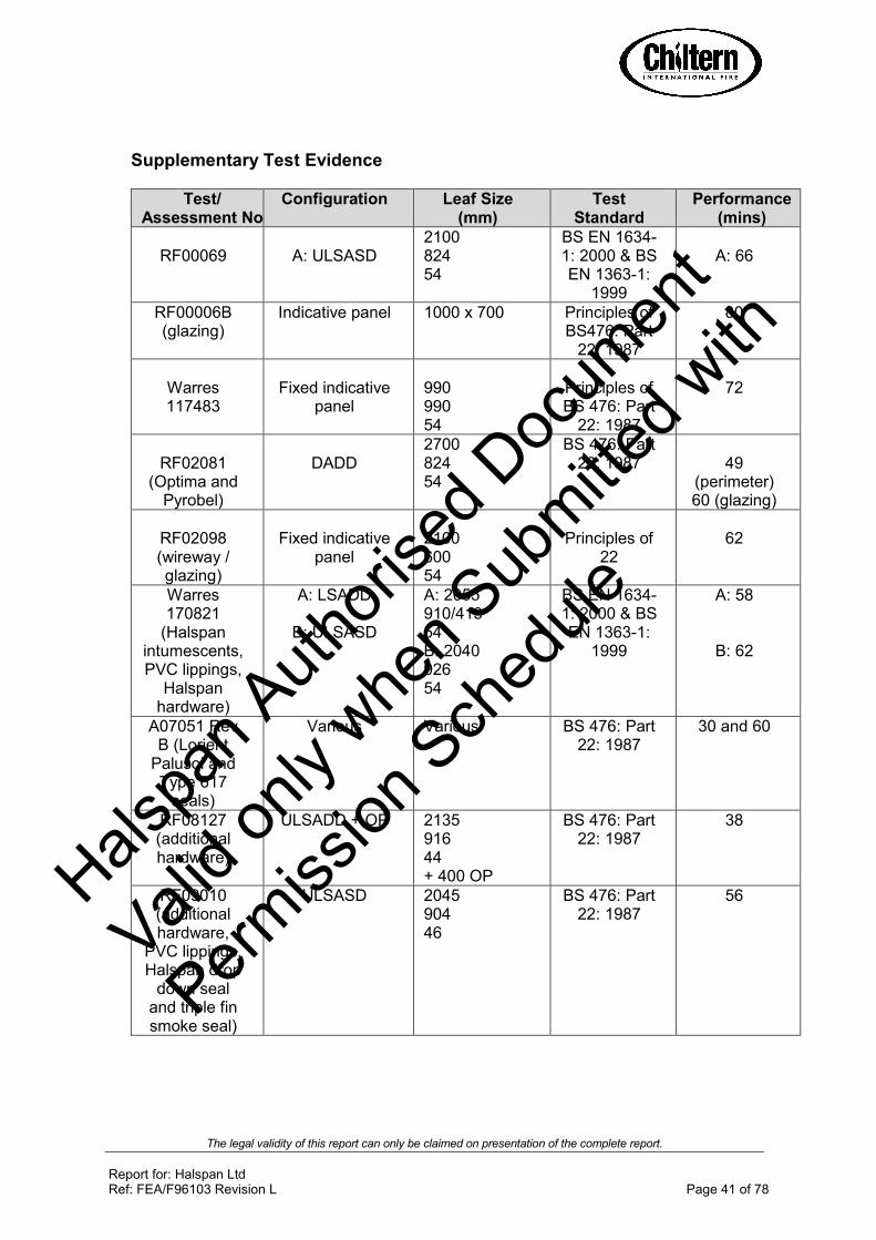
Supplementary Test Evidence
Test/ Assessment No
Configuration Leaf Size (mm)
Test Standard
Performance (mins)
RF00069
A: ULSASD
2100 824 54
BS EN 1634-1: 2000 & BS EN 1363-1:
1999
A: 66
RF00006B (glazing)
Indicative panel 1000 x 700 Principles of BS476: Part
22: 1987
80
Warres 117483
Fixed indicative
panel
990 990 54
Principles of BS 476: Part
22: 1987
72
RF02081
(Optima and Pyrobel)
DADD
2700 824 54
BS 476: Part 22: 1987
49
(perimeter) 60 (glazing)
RF02098 (wireway / glazing)
Fixed indicative
panel
2100 600 54
Principles of
22
62
Warres 170821
(Halspan intumescents, PVC lippings,
Halspan hardware)
A: LSADD
B: ULSASD
A: 2055 910/413 54 B: 2040 926 54
BS EN 1634-1: 2000 & BS EN 1363-1:
1999
A: 58
B: 62
A07051 Rev B (Lorient
Palusol and Type 617
seals)
Various Various BS 476: Part 22: 1987
30 and 60
RF08127 (additional hardware)
ULSADD + OP 2135 916 44 + 400 OP
BS 476: Part 22: 1987
38
RF09010 (additional hardware,
PVC lippings, Halspan drop
down seal and triple fin smoke seal)
ULSASD 2045 904 46
BS 476: Part 22: 1987
56 Halspa
n Auth
orise
d Doc
umen
t
Valid o
nly w
hen S
ubmitte
d with
Permiss
ion S
ched
ule
The legal validity of this report can only be claimed on presentation of the complete report.
Report for: Halspan Ltd Ref: FEA/F96103 Revision L Page 42 of 78
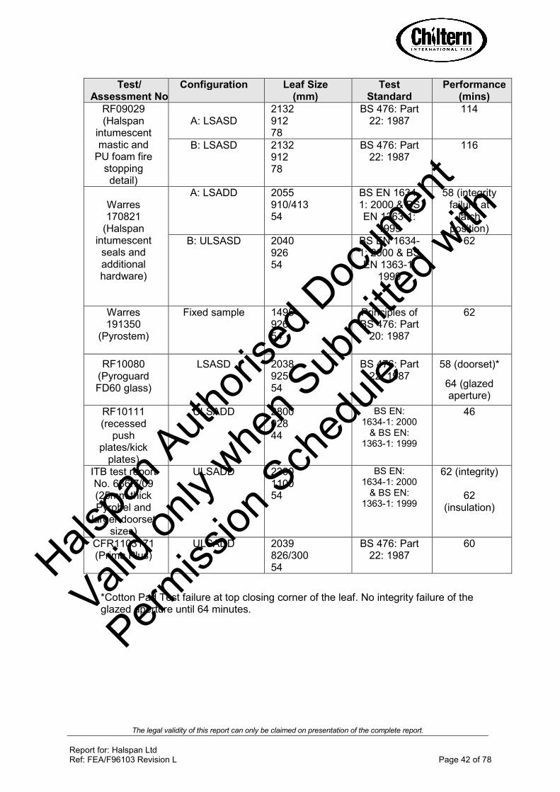
Test/ Assessment No
Configuration Leaf Size (mm)
Test Standard
Performance (mins)
RF09029 (Halspan
intumescent mastic and
PU foam fire stopping detail)
A: LSASD
2132 912 78
BS 476: Part 22: 1987
114
B: LSASD
2132 912 78
BS 476: Part 22: 1987
116
Warres 170821
(Halspan intumescent seals and additional hardware)
A: LSADD 2055 910/413 54
BS EN 1634-1: 2000 & BS EN 1363-1:
1999
58 (integrity failure at
latch position)
B: ULSASD 2040 926 54
BS EN 1634-1: 2000 & BS EN 1363-1:
1999
62
Warres 191350
(Pyrostem)
Fixed sample 1495 926 54
Principles of BS 476: Part
20: 1987
62
RF10080 (Pyroguard FD60 glass)
LSASD 2038 925 54
BS 476: Part 22: 1987
58 (doorset)*
64 (glazed aperture)
RF10111 (recessed
push plates/kick
plates)
ULSADD 2800 928 44
BS EN: 1634-1: 2000
& BS EN: 1363-1: 1999
46
ITB test report No. 636.7/09 (25mm thick Pyrobel and
larger doorset sizes)
ULSADD 2300 1100 54
BS EN: 1634-1: 2000
& BS EN: 1363-1: 1999
62 (integrity)
62 (insulation)
CFR1103171 (Prima Plus)
ULSADD 2039 826/300 54
BS 476: Part 22: 1987
60
*Cotton Pad Test failure at top closing corner of the leaf. No integrity failure of the glazed aperture until 64 minutes.
Halspa
n Auth
orise
d Doc
umen
t
Valid o
nly w
hen S
ubmitte
d with
Permiss
ion S
ched
ule

The legal validity of this report can only be claimed on presentation of the complete report.
Report for: Halspan Ltd Ref: FEA/F96103 Revision L Page 43 of 78
Appendix D Revisions
Revision No Date Description
D 23.5.00 Revalidation and update to include Halspan 60 steel/aluminium frame doorsets and all additional test evidence
E – CIFL ref A01207 14.12.01 5 year revalidation and update including additional test evidence
F – CIFL ref A03031 18.6.03 Incorporation of additional test data to justify the use of Sureguard edge protectors and sheet facing, increase the glazing options, allow the use of wireways and MDF frames and to appropriately amend the maximum leaf dimensions. Extra ironmongery items were also incorporated.
G – CIFL ref A05007 24.01.05 Update to include new test data covering lippings, ironmongery, glazing, intumescent seals and framing.
H – CIFL ref A10028 19.07.10 Update to include new test data covering hardware, glazing, intumescent seals and fire stopping details. The report has been technically reviewed and revalidated for a further 5 year period.
I – CIFL ref A10028 21.10.10 Update to include grooves with hardwood inserts, re-instate security viewers, new sealing to structural opening section, recessed push/kick plates, 25mm thick Pyrobel glass added and larger doorset sizes assessed
J – CIFL ref A11177 5.10.11 Update to include test evidence for Prima Plus design. Scope of application for Prima Plus design is contained in appendix G
K – CIFL ref A12065 9.05.12 Update to include large leaf sizes based on test RF07128 and inclusion of Pilkington Pyroshield 2 scope
L – CIFL ref A12292 23.11.12 Update to include Pyroguard FD60 glass based on test RF10080
Halspa
n Auth
orise
d Doc
umen
t
Valid o
nly w
hen S
ubmitte
d with
Permiss
ion S
ched
ule

The legal validity of this report can only be claimed on presentation of the complete report.
Report for: Halspan Ltd Ref: FEA/F96103 Revision L Page 44 of 78
Appendix E PVC Edge Protectors
Halspa
n Auth
orise
d Doc
umen
t
Valid o
nly w
hen S
ubmitte
d with
Permiss
ion S
ched
ule

The legal validity of this report can only be claimed on presentation of the complete report.
Report for: Halspan Ltd Ref: FEA/F96103 Revision L Page 45 of 78
Appendix F
Data Sheets for
Halspan® 60 Prima
60 Minute Fire resisting Doorsets
Halspa
n Auth
orise
d Doc
umen
t
Valid o
nly w
hen S
ubmitte
d with
Permiss
ion S
ched
ule

The legal validity of this report can only be claimed on presentation of the complete report.
Report for: Halspan Ltd Ref: FEA/F96103 Revision L Page 46 of 78
Maximum Door Leaf Size
2125
2150
2175
2200
2225
2250
2275
2300
910915920925930935940945950
Width (mm)
Heig
ht
(mm
)
LSASD ULSASD & DASD
Halspan® 60 Prima Doorsets – 60 Minutes Fire Resistance
Latched and Unlatched Single Acting & Double Acting Single Doorsets – Reduced Intumescent
Configuration Height (mm) Width (mm)
Leaf Sizes
LSASD From:
To:
2135 x 948
2303 x 915
ULSASD & DASD
From:
To:
2135 x 923
2253 x 915
Maximum Overpanel height (mm) Transomed 2000
Glazing
Maximum Glazed Area:
0.82m2 (see section 7 for details and see
section 7.6 for 1.33m2 option)
Approved systems: See section 7 and appendix B
Frame specification (see section 8)
Material: Hardwood
Min. Section (mm): 70 x 32
Min. Density(kg/m3): 640
Intumescent Materials: PVC encapsulated Palusol 100 or Type 617 Head 1 No 20 x 4mm exposed and centrally fitted in the frame reveal.
Jambs: 1 No 20 x 4mm exposed and centrally fitted in the frame reveal. Hardware Protection: see section 12
Halspa
n Auth
orise
d Doc
umen
t
Valid o
nly w
hen S
ubmitte
d with
Permiss
ion S
ched
ule

The legal validity of this report can only be claimed on presentation of the complete report.
Report for: Halspan Ltd Ref: FEA/F96103 Revision L Page 47 of 78
Maximum Door Leaf Size
2130
2140
2150
2160
2170
2180
2190
2200
2210
820825830835840845850855860
Width (mm)
He
igh
t (m
m)
LSADD ULSADD&DADD
Halspan® 60 Prima Doorsets – 60 Minutes Fire Resistance
Latched and Unlatched Single Acting & Double Acting Double Doorsets – Reduced Intumescent
Configuration Height (mm) Width (mm)
Leaf Sizes
LSADD From:
To:
2135 x 858
2203 x 826
ULSADD & DADD
From:
To:
2135 x 833
2153 x 826
Maximum Overpanel height (mm)
1500
Glazing
Maximum Glazed Area:
0.82m2 (see section 7 for details and see section 7.6
for 1.33m2 option)
Approved systems: See section 7 and appendix B
Frame specification (see section 8 for details)
Material: Hardwood
Min. Section (mm): 70 x 32
Min. Density(kg/m3): 640
Intumescent Materials: PVC Encapsulated Palusol 100 or Type 617 Head:
1No 25 x 4mm exposed and fitted centrally in the frame reveal. Meeting Edges: Square: 1No 25 x 4mm exposed and fitted centrally in one leaf edge only. Rebated: 1No 15 x 4mm exposed and fitted centrally in the rebate of both leaf edges. Jambs: 1No 25 x 4mm exposed and fitted centrally in the frame reveal. Hardware Protection: see section 12
Halspa
n Auth
orise
d Doc
umen
t
Valid o
nly w
hen S
ubmitte
d with
Permiss
ion S
ched
ule

The legal validity of this report can only be claimed on presentation of the complete report.
Report for: Halspan Ltd Ref: FEA/F96103 Revision L Page 48 of 78
Maximum Door Leaf Size
2200
2250
2300
2350
2400
2450
2500
10001050110011501200
Width (mm)
Heig
ht (m
m)
LSASD ULSASD & DASD
Halspan® 60 Prima Doorsets – 60 Minutes Fire Resistance
Latched and Unlatched Single Acting & Double Acting Single Doorsets
Configuration Height (mm) Width (mm)
Leaf Sizes
LSASD From:
To:
2300 x 1192
2486 x 1100
ULSASD & DASD
From:
To:
2300 x 1167
2436 x 1100
Maximum Overpanel height (mm) Transomed 2000
Glazing
Maximum Glazed Area:
0.82m2 (see section 7 for details and see
section 7.6 for 1.33m2 option)
Approved systems: See section 7 and appendix B
Frame specification (see section 8 for details)
Material: Hardwood MDF (≤ 2440 high)
Min. Section (mm): 70 x 22 70 x 30
Min. Density(kg/m3): 640 700
Intumescent Materials: PVC encapsulated 500P, Halspan®
Type SLS
Head 2 No 15 x 4mm exposed and fitted 5mm either side of the centreline in the leaf or frame head.
Jambs: 2 No 15 x 4mm exposed and fitted 5mm either side of the centreline in the leaf edge or frame reveal.
Hardware Protection: see section 12
Halspa
n Auth
orise
d Doc
umen
t
Valid o
nly w
hen S
ubmitte
d with
Permiss
ion S
ched
ule

The legal validity of this report can only be claimed on presentation of the complete report.
Report for: Halspan Ltd Ref: FEA/F96103 Revision L Page 49 of 78
Maximum Door Leaf Size
2100
2200
2300
2400
2500
2600
2700
2800
900950100010501100115012001250
Width (mm)
Heig
ht (m
m)
LSASD ULSASD & DASD
Halspan® 60 Prima Doorsets – 60 Minutes Fire Resistance
Latched and Unlatched Single Acting & Double Acting Single Doorsets
Configuration Height (mm) Width (mm)
Leaf Sizes
LSASD From:
To:
2130 x 1227
2799 x 915
ULSASD & DASD
From:
To:
2130 x 1202
2749 x 915
Maximum Overpanel height (mm) Transomed 2000
Glazing
Maximum Glazed Area:
0.82m2 (see section 7 for details and see
section 7.6 for 1.33m2 option)
Approved systems: See section 7 and appendix B
Frame specification (see section 8 for details)
Material: Hardwood MDF (≤ 2440 high)
Min. Section (mm): 70 x 22 70 x 30
Min. Density(kg/m3): 640 700
Intumescent Materials: PVC encapsulated Palusol 100, Type 617, Pyroplex, 500P or Halspan®
Type SLS
Head 2 No 15 x 4mm exposed and fitted 5mm either side of the centreline in the leaf or frame head.
Jambs: 2 No 15 x 4mm exposed and fitted 5mm either side of the centreline in the leaf edge or frame reveal.
Hardware Protection: see section 12
Halspa
n Auth
orise
d Doc
umen
t
Valid o
nly w
hen S
ubmitte
d with
Permiss
ion S
ched
ule

The legal validity of this report can only be claimed on presentation of the complete report.
Report for: Halspan Ltd Ref: FEA/F96103 Revision L Page 50 of 78
Maximum Door Leaf Size
2400
2500
2600
2700
2800
12001250130013501400
Width (mm)
He
ight
(mm
)
LSASD ULSASD & DASD
Halspan® 60 Prima Doorsets – 60 Minutes Fire Resistance
Latched and Unlatched Single Acting & Double Acting Single Doorsets – extended width
Configuration Height (mm) Width (mm)
Leaf Sizes
LSASD From:
To:
2441 x 1384
2735 x 1236
ULSASD & DASD
From:
To:
2441 x 1359
2685 x 1236
Maximum Overpanel height (mm) Transomed 2000
Glazing
Maximum Glazed Area:
0.82m2 (see section 7 for details and see
section 7.6 for 1.33m2 option)
Approved systems: See section 7 and appendix B
Frame specification (see section 8 for details)
Material: Hardwood MDF (≤ 2440 high)
Min. Section (mm): 70 x 22 70 x 30
Min. Density(kg/m3): 640 700
Intumescent Materials: PVC encapsulated Type 617 Head 2 No 15 x 4mm exposed and fitted 5mm either side of the centreline in the leaf or frame head.
Jambs: 2 No 15 x 4mm exposed and fitted 5mm either side of the centreline in the leaf edge or frame reveal.
Hardware Protection: see section 12
Halspa
n Auth
orise
d Doc
umen
t
Valid o
nly w
hen S
ubmitte
d with
Permiss
ion S
ched
ule

The legal validity of this report can only be claimed on presentation of the complete report.
Report for: Halspan Ltd Ref: FEA/F96103 Revision L Page 51 of 78
Maximum Door Leaf Size
2400
2500
2600
2700
1200125013001350
Width (mm)
Heig
ht (m
m)
LSASD ULSASD & DASD
Halspan® 60 Prima Doorsets – 60 Minutes Fire Resistance
Latched and Unlatched Single Acting & Double Acting Single Doorsets – extended width
Configuration Height (mm) Width (mm)
Leaf Sizes
LSASD From:
To:
2441 x 1333
2633 x 1236
ULSASD & DASD
From:
To:
2441 x 1308
2583 x 1236
Maximum Overpanel height (mm) Transomed 2000
Glazing
Maximum Glazed Area:
0.82m2 (see section 7 for details and see
section 7.6 for 1.33m2 option)
Approved systems: See section 7 and appendix B
Frame specification (see section 8 for details)
Material: Hardwood MDF (≤ 2440 high)
Min. Section (mm): 70 x 22 70 x 30
Min. Density(kg/m3): 640 700
Intumescent Materials: PVC encapsulated Palusol 100 Head 2 No 15 x 4mm exposed and fitted 5mm either side of the centreline in the leaf or frame head.
Jambs: 2 No 15 x 4mm exposed and fitted 5mm either side of the centreline in the leaf edge or frame reveal.
Hardware Protection: see section 12
Halspa
n Auth
orise
d Doc
umen
t
Valid o
nly w
hen S
ubmitte
d with
Permiss
ion S
ched
ule

The legal validity of this report can only be claimed on presentation of the complete report.
Report for: Halspan Ltd Ref: FEA/F96103 Revision L Page 52 of 78
Maximum Door Leaf Size
2690
2740
2790
2840
2890
2940
2990
3040
8208458708959209459709951020
Width (mm)
Heig
ht
(mm
)
LSASD ULSASD&DASD
Halspan® 60 Prima Doorsets – 60 Minutes Fire Resistance
Latched and Unlatched Single Acting & Double Acting Single Doorsets – Extended Height
Configuration Height (mm) Width (mm)
Leaf Sizes
LSASD From:
To:
2700 x 1000
3050 x 825
ULSASD & DASD
From:
To:
2700 x 975
3000 x 825
Maximum Overpanel height (mm)
Transomed 2000
Glazing
Maximum Glazed Area:
0.82m2 (see section 7 for details and see section 7.6
for 1.33m2 option)
Approved systems: See section 7 and appendix B
Frame specification (see section 8 for details)
Material: Hardwood
Min. Section (mm): 70 x 22
Min. Density (kg/m3): 640
Intumescent Materials: PVC Encapsulated Palusol 100, Type 617, Therm-A-Seal, Pyroplex, 500P or Halspan®
Type
SLS Head: 2No 15 x 4mm exposed and fitted 5mm either side of the centreline in the leaf or frame head. Jambs: 2No 15 x 4mm exposed and fitted 5mm either side of the centreline in the leaf edge or frame reveal.
Hardware Protection: see section 12
Halspa
n Auth
orise
d Doc
umen
t
Valid o
nly w
hen S
ubmitte
d with
Permiss
ion S
ched
ule

The legal validity of this report can only be claimed on presentation of the complete report.
Report for: Halspan Ltd Ref: FEA/F96103 Revision L Page 53 of 78
Maximum Door Leaf Size
2100
2200
2300
2400
2500
2600
2700
900925950975100010251050107511001125115011751200
Width (mm)
He
igh
t (m
m)
LSASD+OP ULSASD+OP & DASD+OP
Halspan® 60 Prima Doorsets – 60 Minutes Fire Resistance
Latched and Unlatched Single Acting & Double Acting Single Doorsets + Overpanel (extended width)
Configuration Height (mm) Width (mm)
Leaf Sizes
LSASD+OP From:
To:
2130 x 1177
2699 x 915
ULSASD+OP & DASD+OP
From:
To:
2130 x 1152
2649 x 915
Maximum Overpanel height (mm)
2000
Glazing
Maximum Glazed Area:
0.82m2 (see section 7 for details and see section 7.6
for 1.33m2 option)
Approved systems: See section 7 and appendix B
Frame specification (see section 8 for details)
Material: Hardwood MDF (≤ 2440 high)
Min. Section (mm): 70 x 22 70 x 30
Min. Density(kg/m3): 640 700
Intumescent Materials: PVC Encapsulated Palusol 100, Type 617, Therm-A-Seal, Pyroplex, 500P or Halspan®
Type
SLS Head: Square: 1No 38 x 4mm exposed and fitted centrally in the leaf or bottom of overpanel. Rebated: 2 No 15 x 4mm exposed and fitted centrally with one in the rebate and one in the upstand of the overpanel plus 1No
10 x 4mm in the corner of the leaf head rebates. Jambs and Overpanel: 2No 15 x 4mm exposed and fitted 5mm either side of the centreline the leaf edge or frame reveal. Hardware Protection: see section 12
Halspa
n Auth
orise
d Doc
umen
t
Valid o
nly w
hen S
ubmitte
d with
Permiss
ion S
ched
ule

The legal validity of this report can only be claimed on presentation of the complete report.
Report for: Halspan Ltd Ref: FEA/F96103 Revision L Page 54 of 78
Maximum Door Leaf Size
2690
2740
2790
2840
2890
2940
820830840850860870880890900910920930940950960
Width (mm)
He
igh
t (m
m)
LSASD+OP ULSASD+OP & DASD+OP
Halspan® 60 Prima Doorsets – 60 Minutes Fire Resistance
Latched and Unlatched Single Acting & Double Acting Single Doorsets + Overpanel (extended height)
Configuration Height (mm) Width (mm)
Leaf Sizes
LSASD+OP From:
To:
2700 x 950
2950 x 825
ULSASD+OP & DASD+OP
From:
To:
2700 x 925
2900 x 825
Maximum Overpanel height (mm) 2000
Glazing
Maximum Glazed Area:
0.82m2 (see section 7 for details and see section 7.6
for 1.33m2 option)
Approved systems: See section 7 and appendix B
Frame specification (see section 8 for details)
Material: Hardwood
Min. Section (mm): 70 x 22
Min. Density(kg/m3): 640
Intumescent Materials: PVC Encapsulated Palusol 100, Type 617, Therm-A-Seal, Pyroplex, 500P or Halspan®
Type SLS
Head: Square: 1No 38 x 4mm exposed and fitted centrally in the leaf or bottom of overpanel. Rebated: 2 No 15 x 4mm exposed and fitted centrally with one in the rebate and one in the upstand of the overpanel plus 1No 10
x 4mm in the corner of the leaf head rebates. Jambs and Overpanel: 2No 15 x 4mm exposed and fitted 5mm either side of the centreline the leaf edge or frame reveal.
Hardware Protection: see section 12
Halspa
n Auth
orise
d Doc
umen
t
Valid o
nly w
hen S
ubmitte
d with
Permiss
ion S
ched
ule

The legal validity of this report can only be claimed on presentation of the complete report.
Report for: Halspan Ltd Ref: FEA/F96103 Revision L Page 55 of 78
Maximum Door Leaf Size
2140
2165
2190
2215
2240
2265
2290
890900910920930940950960970980
Width (mm)
He
igh
t (m
m)
LSADD ULSADD&DADD
Halspan® 60 Prima Doorsets – 60 Minutes Fire Resistance
Latched and Unlatched Single Acting & Double Acting Double Doorsets
Configuration Height (mm) Width (mm)
Leaf Sizes
LSADD From:
To:
2150 x 975
2300 x 900
ULSADD & DADD
From:
To:
2150 x 950
2250 x 900
Maximum Overpanel height (mm) Transomed 1500
Glazing
Maximum Glazed Area:
0.82m2 (see section 7 for details and see section 7.6
for 1.33m2 option)
Approved systems: See section 7 and appendix B
Frame specification (see section 8 for details)
Material: Hardwood MDF (≤ 2440 high)
Min. Section (mm): 70 x 22 70 x 30
Min. Density(kg/m3): 640 700
Intumescent Materials: PVC Encapsulated Palusol 100, Type 617, Therm-A-Seal, Pyroplex, 500P or Halspan®
Type SLS
Head: Square: 2No 15 x 4mm exposed and fitted 5mm either side of the centreline in the leaf or frame head.
Meeting Edges: Square: 2No 15 x 4mm exposed and fitted 5mm either side of the centreline in one leaf edge only. Rebated: 2 No 15 x 4mm exposed with each seal fitted centrally in the rebate of each leaf. Jambs: 2No 15 x 4mm exposed and fitted 5mm either side of the centreline in the leaf edge or frame reveal.
Hardware Protection: see section 12
Halspa
n Auth
orise
d Doc
umen
t
Valid o
nly w
hen S
ubmitte
d with
Permiss
ion S
ched
ule

The legal validity of this report can only be claimed on presentation of the complete report.
Report for: Halspan Ltd Ref: FEA/F96103 Revision L Page 56 of 78
Maximum Door Leaf Size
2290
2315
2340
2365
2390
1090110011101120113011401150
Width (mm)
He
igh
t (m
m)
LSADD ULSADD&DADD
Halspan® 60 Prima Doorsets – 60 Minutes Fire Resistance
Latched and Unlatched Single Acting & Double Acting Double Doorsets – Extended Width Configuration Height (mm) Width (mm)
Leaf Sizes
LSADD From:
To:
2300 x 1142
2386 x 1100
ULSADD & DADD
From:
To:
2300 x 1117
2336 x 1100
Maximum Overpanel height (mm) Transomed 1500
Glazing
Maximum Glazed Area:
0.82m2 (see section 7 for details and see section 7.6
for 1.33m2 option)
Approved systems: See section 7 and appendix B
Frame specification (see section 8 for details)
Material: Hardwood MDF (≤ 2440 high)
Min. Section (mm): 70 x 22 70 x 30
Min. Density(kg/m3): 640 700
Intumescent Materials: PVC Encapsulated 500P or Halspan®
Type SLS
Head: Square: 2No 15 x 4mm exposed and fitted 5mm either side of the centreline in the leaf or frame head.
Meeting Edges: Square: 2No 15 x 4mm exposed and fitted 5mm either side of the centreline in one leaf edge only. Jambs: 2No 15 x 4mm exposed and fitted 5mm either side of the centreline in the leaf edge or frame reveal.
Hardware Protection: see section 12
Halspa
n Auth
orise
d Doc
umen
t
Valid o
nly w
hen S
ubmitte
d with
Permiss
ion S
ched
ule

The legal validity of this report can only be claimed on presentation of the complete report.
Report for: Halspan Ltd Ref: FEA/F96103 Revision L Page 57 of 78
Maximum Door Leaf Size
2675
2700
2725
2750
2775
2800
2825
2850
2875
820830840850860870880890900910
Width (mm)
He
igh
t (m
m)
LSADD ULSADD&DADD
Halspan® 60 Prima Doorsets – 60 Minutes Fire Resistance
Latched and Unlatched Single Acting & Double Acting Double Doorsets – Extended Height
Configuration Height (mm) Width (mm)
Leaf Sizes
LSADD From:
To:
2700 x 900
2850 x 825
ULSADD & DADD
From:
To:
2700 x 875
2800 x 825
Maximum Overpanel height (mm) Transomed 1500
Glazing
Maximum Glazed Area:
0.82m2
(see section 7 for details and see section 7.6 for 1.33m
2 option)
Approved systems: See section 7 and appendix B
Frame specification (see section 8 for details)
Material: Hardwood
Min. Section (mm): 70 x 22
Min. Density(kg/m3): 640
Intumescent Materials: PVC Encapsulated Palusol 100, Type 617, Therm-A-Seal, Pyroplex, 500P or Halspan®
Type SLS
Head: Square: 2No 15 x 4mm exposed and fitted 5mm either side of the centreline in the leaf or frame head.
Meeting Edges: Square: 2No 15 x 4mm exposed and fitted 5mm either side of the centreline in one leaf edge only. Rebated: 2 No 15 x 4mm exposed with each seal fitted centrally in the rebate of each leaf. Jambs: 2No 15 x 4mm exposed and fitted 5mm either side of the centreline in the leaf edge or frame reveal.
Hardware Protection: see section 12
Halspa
n Auth
orise
d Doc
umen
t
Valid o
nly w
hen S
ubmitte
d with
Permiss
ion S
ched
ule

The legal validity of this report can only be claimed on presentation of the complete report.
Report for: Halspan Ltd Ref: FEA/F96103 Revision L Page 58 of 78
Maximum Door Leaf Size
2140
2150
2160
2170
2180
2190
2200
2210
890895900905910915920925930
Width (mm)
He
igh
t (m
m)
LSADD+OP ULSADD+OP & DADD+OP
Halspan® 60 Prima Doorsets – 60 Minutes Fire Resistance
Latched & Unlatched Single Acting & Double Acting Double Doorsets+OP (extended width)
Configuration Height (mm) Width (mm)
Leaf Sizes
LSADD+OP From:
To:
2150 x 925
2200 x 900
ULSADD+OP & DADD+OP
Max:
2150 x 900
Maximum Overpanel height (mm) 1500
Glazing
Maximum Glazed Area:
0.82m2 (see section 7 for details and see section 7.6
for 1.33m2 option)
Approved systems: See section 7 and appendix B
Frame specification (see section 8 for details)
Material: Hardwood MDF (≤ 2440 high)
Min. Section (mm): 70 x 22 70 x 30
Min. Density(kg/m3): 640 700
Intumescent Materials: PVC Encapsulated Palusol 100, Type 617, Therm-A-Seal, Pyroplex, 500P or Halspan®
Type SLS
Head: Square: 1No 38 x 4mm exposed and fitted centrally in the leaf or bottom of overpanel. Rebated: 2 No 15 x 4mm exposed and fitted centrally with one seal in the rebate and one seal in the upstand of the overpanel
plus 1No 10 x 4mm in the corner of the leaf head rebates (maximum leaf height with rebates is 2200mm). Meeting Edges: Square: 2No 15 x 4mm exposed and fitted 5mm either side of the centreline in one leaf edge, and 1No 10 x 4mm fitted centrally in
the opposite leaf. Jambs & Overpanel (overpanel intumescent is optional): 2No 15 x 4mm exposed and fitted 5mm either side of the centreline in the leaf edge or frame reveal. Hardware Protection: see section 12
Halspa
n Auth
orise
d Doc
umen
t
Valid o
nly w
hen S
ubmitte
d with
Permiss
ion S
ched
ule

The legal validity of this report can only be claimed on presentation of the complete report.
Report for: Halspan Ltd Ref: FEA/F96103 Revision L Page 59 of 78
Maximum Door Leaf Size
2690
2700
2710
2720
2730
2740
2750
2760
810820830840850
Width (mm)
He
igh
t (m
m)
LSADD+OP ULSADD+OP & DADD+OP
Halspan® 60 Prima Doorsets – 60 Minutes Fire Resistance
Latched & Unlatched Single Acting & Double Acting Double Doorsets+OP (extended height)
Configuration Height (mm) Width (mm)
Leaf Sizes
LSADD+OP From:
To:
2700 x 850
2750 x 825
ULSADD+OP & DADD+OP
Max:
2700 x 825
Maximum Overpanel height (mm) 1500
Glazing
Maximum Glazed Area:
0.82m2 (see section 7 for details and see section 7.6
for 1.33m2 option)
Approved systems: See section 7 and appendix B
Frame specification (see section 8 for details)
Material: Hardwood
Min. Section (mm): 70 x 22
Min. Density(kg/m3): 640
Intumescent Materials: PVC Encapsulated Palusol 100, Type 617, Therm-A-Seal, Pyroplex, 500P or Halspan®
Type SLS
Head: Square: 1No 38 x 4mm exposed and fitted centrally in the leaf or bottom of overpanel. Rebated: 2 No 15 x 4mm exposed and fitted centrally with one seal in the rebate and one seal in the upstand of the overpanel
plus 1No 10 x 4mm in the corner of the leaf head rebates (maximum leaf height with rebates is 2200mm). Meeting Edges: Square: 2No 15 x 4mm exposed and fitted 5mm either side of the centreline in one leaf edge, and 1No 10 x 4mm fitted centrally in
the opposite leaf. Jambs & Overpanel (overpanel intumescent is optional): 2No 15 x 4mm exposed and fitted 5mm either side of the centreline in the leaf edge or frame reveal. Hardware Protection: see section 12
Halspa
n Auth
orise
d Doc
umen
t
Valid o
nly w
hen S
ubmitte
d with
Permiss
ion S
ched
ule

The legal validity of this report can only be claimed on presentation of the complete report.
Report for: Halspan Ltd Ref: FEA/F96103 Revision L Page 60 of 78
Maximum Door Leaf Size
2000
2050
2100
2150
2200
2250
2300
2350
2400
800825850875900925950975
Width (mm)
Heig
ht
(mm
)
LSASD ULSASD & DASD
Halspan® 60 Prima Hollow Steel Frame Doorsets – 60 Minutes Fire Resistance
Latched and Unlatched Single Acting & Double Acting Single Doorsets
Configuration Height (mm) Width (mm)
Leaf Sizes
LSASD From:
To:
2042 x 953
2345 x 826
ULSASD & DASD
From:
To:
2042 x 928
2295 x 826
Maximum Overpanel height (mm) na
Glazing
Maximum Glazed Area:
0.82m2 (see section 7 for details and see
section 7.6 for 1.33m2 option)
Approved systems: See section 7 and appendix B
Frame specification Material: Mild or stainless steel – See Appendix A
Min. Section (mm): see section 5 in appendix A
Intumescent Materials: Head: H60 (details in confidence on file at CIFL)
Jambs: H60 (details in confidence on file at CIFL) Hardware Protection: see section 12
Halspa
n Auth
orise
d Doc
umen
t
Valid o
nly w
hen S
ubmitte
d with
Permiss
ion S
ched
ule

The legal validity of this report can only be claimed on presentation of the complete report.
Report for: Halspan Ltd Ref: FEA/F96103 Revision L Page 61 of 78
Maximum Door Leaf Size
2000
2025
2050
2075
2100
2125
2150
2175
2200
800810820830840850860870880890900910
Width (mm)
He
igh
t (m
m)
LSASD+OP ULSASD+OP & DASD+OP
Halspan® 60 Prima Hollow Steel Frame Doorsets – 60 Minutes Fire Resistance
Latched and Unlatched Single Acting & Double Acting Single Doorsets + Overpanel
Configuration Height (mm) Width (mm)
Leaf Sizes
LSASD+OP From:
To:
2042 x 901
2192 x 826
ULSASD+OP & DASD+OP
From:
To:
2042 x 876
2142 x 826
Maximum Overpanel height (mm) 500
Glazing
Maximum Glazed Area:
0.82m2 (see section 7 for details and see
section 7.6 for 1.33m2 option)
Approved systems: See section 7 and appendix B
Frame specification Material: Mild or stainless steel – see Appendix A
Min. Section (mm): see section 5 in appendix A
Intumescent Materials: Therm-A-Seal Head: Square: 1No 38 x 4mm exposed and fitted centrally in the leaf or bottom of the overpanel. Rebated: 2 No 15 x 4mm exposed and fitted centrally with one seal in the rebate and one seal in the upstand of the
overpanel plus 1No 10 x 4mm in the corner of the leaf head rebates. Jambs& Overpanel: H60 (details in confidence on file at CIFL).
Hardware Protection: see section 12
Halspa
n Auth
orise
d Doc
umen
t
Valid o
nly w
hen S
ubmitte
d with
Permiss
ion S
ched
ule

The legal validity of this report can only be claimed on presentation of the complete report.
Report for: Halspan Ltd Ref: FEA/F96103 Revision L Page 62 of 78
Maximum Door Leaf Size
2000
2020
2040
2060
2080
2100
2120
2140
2160
2180
2200
2220
2240
2260
2280
2300
800810820830840850860870880890900910920
Width (mm)
Heig
ht (m
m)
LSADD ULSADD&DADD
Halspan® 60 Prima Hollow Steel Frame Doorsets – 60 Minutes Fire Resistance
Latched and Unlatched Single Acting & Double Acting Double Doorsets
Configuration Height (mm) Width (mm)
Leaf Sizes
LSADD From:
To:
2042 x 903
2245 x 826
ULSADD & DADD
From:
To:
2042 x 888
2195 x 826
Maximum Overpanel height (mm) na
Glazing
Maximum Glazed Area:
0.82m2 (see section 7 for details and see
section 7.6 for 1.33m2 option)
Approved systems: See section 7 and appendix B
Frame specification Material: Mild or stainless steel – see Appendix A
Min. Section (mm): see section 5 in appendix A
Intumescent Materials: Therm-A-Seal Head: H60 (details in confidence on file at CIFL).
Meeting Edges: Square: 2No 10 x 4mm exposed and fitted 5mm either side of the centreline in one leaf edge and 1No 10 x 4mm fitted
centrally in the opposite leaf. Jambs: H60 (details in confidence on file at CIFL). Hardware Protection: see section 12
Halspa
n Auth
orise
d Doc
umen
t
Valid o
nly w
hen S
ubmitte
d with
Permiss
ion S
ched
ule

The legal validity of this report can only be claimed on presentation of the complete report.
Report for: Halspan Ltd Ref: FEA/F96103 Revision L Page 63 of 78
Maximum Door Leaf Size
2000
2025
2050
2075
2100
810820830840850860
Width (mm)
He
igh
t (m
m)
LSADD+OP ULSADD+OP & DADD+OP
Halspan® 60 Prima Hollow Steel Frame Doorsets – 60 Minutes Fire Resistance
Latched and Unlatched Single Acting & Double Acting Double Doorsets + Overpanel
Configuration Height (mm) Width (mm)
Leaf Sizes
LSADD+OP From:
To:
2042 x 851
2092 x 826
ULSADD+OP & DADD+OP
Max:
2042 x 826
Maximum Overpanel height (mm) 500
Glazing
Maximum Glazed Area:
0.82m2 (see section 7 for details and see
section 7.6 for 1.33m2 option)
Approved systems: See section 7 and appendix B
Frame specification Material: Mild or stainless steel – see Appendix A
Min. Section (mm): see section 5 in appendix A
Intumescent Materials: Therm-A-Seal Head: Square: 1No 38 x 4mm exposed and fitted centrally in the leaf or bottom of the overpanel. Rebated: 2 No 15 x 4mm exposed and fitted centrally with one seal in the rebate and one seal in the upstand of the
overpanel plus 1No 10 x 4mm in the corner of the leaf head rebates. Meeting Edges: Square: 2No 10 x 4mm exposed and fitted 5mm either side of the centreline in one leaf edge and 1No 10 x 4mm fitted
centrally in the opposite leaf. Jambs & Overpanel: H60 (details in confidence on file at CIFL).
Hardware Protection: see section 12
Halspa
n Auth
orise
d Doc
umen
t
Valid o
nly w
hen S
ubmitte
d with
Permiss
ion S
ched
ule
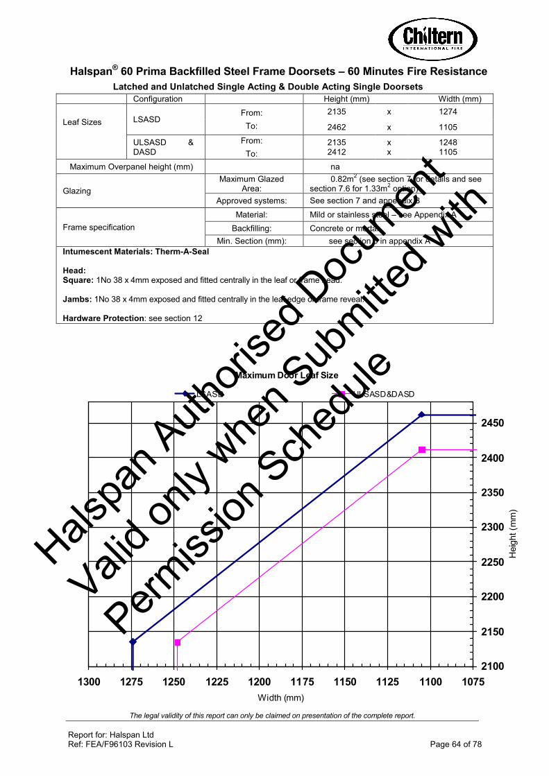
The legal validity of this report can only be claimed on presentation of the complete report.
Report for: Halspan Ltd Ref: FEA/F96103 Revision L Page 64 of 78
Maximum Door Leaf Size
2100
2150
2200
2250
2300
2350
2400
2450
1075110011251150117512001225125012751300
Width (mm)
Heig
ht (m
m)
LSASD ULSASD&DASD
Halspan® 60 Prima Backfilled Steel Frame Doorsets – 60 Minutes Fire Resistance
Latched and Unlatched Single Acting & Double Acting Single Doorsets
Configuration Height (mm) Width (mm)
Leaf Sizes
LSASD From:
To:
2135 x 1274
2462 x 1105
ULSASD & DASD
From:
To:
2135 2412
x x
1248 1105
Maximum Overpanel height (mm) na
Glazing
Maximum Glazed Area:
0.82m2 (see section 7 for details and see
section 7.6 for 1.33m2 option)
Approved systems: See section 7 and appendix B
Frame specification
Material: Mild or stainless steel – see Appendix A
Backfilling: Concrete or mortar
Min. Section (mm): see section 5 in appendix A
Intumescent Materials: Therm-A-Seal Head: Square: 1No 38 x 4mm exposed and fitted centrally in the leaf or frame head.
Jambs: 1No 38 x 4mm exposed and fitted centrally in the leaf edge or frame reveal.
Hardware Protection: see section 12
Halspa
n Auth
orise
d Doc
umen
t
Valid o
nly w
hen S
ubmitte
d with
Permiss
ion S
ched
ule
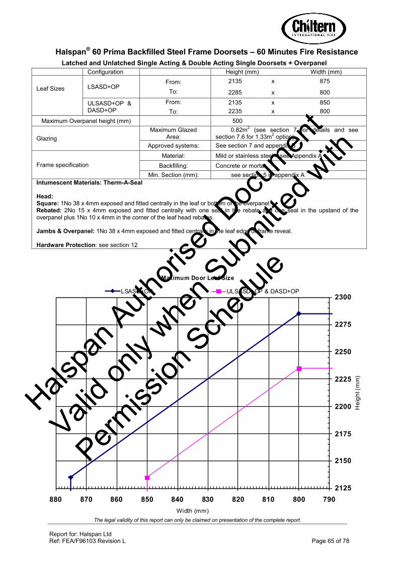
The legal validity of this report can only be claimed on presentation of the complete report.
Report for: Halspan Ltd Ref: FEA/F96103 Revision L Page 65 of 78
Maximum Door Leaf Size
2125
2150
2175
2200
2225
2250
2275
2300
790800810820830840850860870880
Width (mm)
He
igh
t (m
m)
LSASD+OP ULSASD+OP & DASD+OP
Halspan® 60 Prima Backfilled Steel Frame Doorsets – 60 Minutes Fire Resistance
Latched and Unlatched Single Acting & Double Acting Single Doorsets + Overpanel
Configuration Height (mm) Width (mm)
Leaf Sizes
LSASD+OP From:
To:
2135 x 875
2285 x 800
ULSASD+OP & DASD+OP
From:
To:
2135 x 850
2235 x 800
Maximum Overpanel height (mm) 500
Glazing
Maximum Glazed Area:
0.82m2 (see section 7 for details and see
section 7.6 for 1.33m2 option)
Approved systems: See section 7 and appendix B
Frame specification
Material: Mild or stainless steel – see Appendix A
Backfilling: Concrete or mortar
Min. Section (mm): see section 5 in appendix A
Intumescent Materials: Therm-A-Seal Head: Square: 1No 38 x 4mm exposed and fitted centrally in the leaf or bottom of the overpanel. Rebated: 2No 15 x 4mm exposed and fitted centrally with one seal in the rebate and one seal in the upstand of the
overpanel plus 1No 10 x 4mm in the corner of the leaf head rebates. Jambs & Overpanel: 1No 38 x 4mm exposed and fitted centrally in the leaf edge or frame reveal.
Hardware Protection: see section 12
Halspa
n Auth
orise
d Doc
umen
t
Valid o
nly w
hen S
ubmitte
d with
Permiss
ion S
ched
ule

The legal validity of this report can only be claimed on presentation of the complete report.
Report for: Halspan Ltd Ref: FEA/F96103 Revision L Page 66 of 78
Maximum Door Leaf Size
2100
2150
2200
2250
2300
2350
2400
2450
2500
790800810820830840850860870880890900910920930940950960
Width (mm)
He
igh
t (m
m)
LSADD ULSADD&DADD
Halspan® 60 Prima Backfilled Steel Frame Doorsets – 60 Minutes Fire Resistance
Latched and Unlatched Single Acting & Double Acting Double Doorsets
Configuration Height (mm) Width (mm)
Leaf Sizes
LSADD From:
To:
2135 x 945
2505 x 800
ULSADD & DADD
From:
To:
2135 x 920
2455 x 800
Maximum Overpanel height (mm) na
Glazing
Maximum Glazed Area:
0.82m2 (see section 7 for details and see
section 7.6 for 1.33m2 option)
Approved systems: See section 7 and appendix B
Frame specification
Material: Mild or stainless steel – see Appendix A
Backfilling: Concrete or mortar
Min. Section (mm): see section 5 in appendix A
Intumescent Materials: Therm-A-Seal Head: 1No 38 x 4mm exposed and fitted centrally in the leaf or frame head. Meeting Edges: Square: 2No 10 x 4mm exposed and fitted 5mm either side of the centreline in one leaf edge and 1No 10 x 4mm fitted
centrally in the opposite leaf. Jambs: 1No 38 x 4mm exposed and fitted centrally in the leaf edge or frame reveal. Hardware Protection: see section 12
Halspa
n Auth
orise
d Doc
umen
t
Valid o
nly w
hen S
ubmitte
d with
Permiss
ion S
ched
ule

The legal validity of this report can only be claimed on presentation of the complete report.
Report for: Halspan Ltd Ref: FEA/F96103 Revision L Page 67 of 78
Maximum Door Leaf Size
2100
2110
2120
2130
2140
2150
2160
2170
2180
2190
2200
780790800810820830
Width (mm)
Heig
ht (m
m)
LSADD+OP ULSADD+OP & DADD+OP
Halspan® 60 Prima Backfilled Steel Frame Doorsets – 60 Minutes Fire Resistance
Latched and Unlatched Single Acting & Double Acting Double Doorsets + Overpanel
Configuration Height (mm) Width (mm)
Leaf Sizes
LSADD+OP From:
To:
2135 x 825
2185 x 800
ULSADD+OP & DADD+OP
Max:
2135 x 800
x
Maximum Overpanel height (mm) 500
Glazing
Maximum Glazed Area:
0.82m2 (see section 7 for details and see
section 7.6 for 1.33m2 option)
Approved systems: See section 7 and appendix B
Frame specification
Material: Mild or stainless steel – see Appendix A
Backfilling: Concrete or mortar
Min. Section (mm): see section 5 in appendix A
Intumescent Materials: Therm-A-Seal Head: Square: 1No 38 x 4mm exposed and fitted centrally in the leaf or bottom of the overpanel. Rebated: 2No 15 x 4mm exposed and fitted centrally with one seal in the rebate and one seal in the upstand of the
overpanel plus 1No 10 x 4mm in the corner of the leaf head rebates. Meeting Edges: Square: 2No 10 x 4mm exposed and fitted 5mm either side of the centreline in one leaf edge and 1No 10 x 4mm fitted
centrally in the opposite leaf. Jambs & Overpanel: 1No 38 x 4mm exposed and fitted centrally in the leaf/overpanel edge or frame reveal.
Hardware Protection: see section 12
Halspa
n Auth
orise
d Doc
umen
t
Valid o
nly w
hen S
ubmitte
d with
Permiss
ion S
ched
ule
The legal validity of this report can only be claimed on presentation of the complete report.
Report for: Halspan Ltd Ref: FEA/F96103 Revision L Page 68 of 78
Appendix G Halspan
® 60 Prima Plus Doorsets
1. Introduction
This appendix contains information relating to Halspan®
60 Prima Plus doorsets. The
assessment uses the same extrapolation and interpretation techniques applied for the main assessment and is an evaluation of the potential fire resistance performance, if the elements were to be tested in accordance with BS476: Part 22: 1987.
All construction details for the Prima Plus design are to remain as stated in the main body of the assessment, unless otherwise specified in the following sections.
2. General Description of Construction
The construction for door leaves of this design comprises a solid sheet of 54mm thick
Halspan®
60 Prima Plus three layered particleboard (nominal density 630kg/m³ +/-
10%). The Halspan®
Prima Plus design has no added urea formaldehyde. Where
specified, the leaves are lipped with hardwood.
3. Leaf Sizes
The approval for increased leaf dimensions is based on test CFR 1103171 and takes into account the margin of over performance above 60 minutes integrity for the design and the characteristics exhibited during test. Data sheets specifying the maximum approved leaf sizes and graphs showing the permitted gradient between maximum height and width are contained at the end of this appendix.
Doorsets with reduced dimensions are deemed to be less onerous. Therefore, doors with dimensions that are less than those given in the data sheets may be manufactured.
4. Configurations
Based on the cited test evidence this assessment covers the following doorset configurations for the Prima Plus design:
Abbreviation Description
LSASD & ULSASD Latched & unlatched single acting single doorset
LSADD & ULSADD Latched & unlatched single acting double doorset
Unequal leaf double doorsets are covered by this assessment with no restriction on the smaller leaf dimension.
5. Leaf Size Adjustment
See section 5 of the main assessment
Halspa
n Auth
orise
d Doc
umen
t
Valid o
nly w
hen S
ubmitte
d with
Permiss
ion S
ched
ule

The legal validity of this report can only be claimed on presentation of the complete report.
Report for: Halspan Ltd Ref: FEA/F96103 Revision L Page 69 of 78
6. Overpanels
Only overpanels fitted with a transom are permitted for the Prima Plus design. See section 6 for construction details
7. Glazing
The maximum assessed glazed area for the Prima Plus design is 0.5m². All other details for glazing given in section 7 of the main assessment must be followed.
8. Door Frames
All door frame options given in section 8 of the main assessment are permitted with the Prima Plus design except for steel.
9. Timber Lippings
Halspan® 60 Prima Plus must be lipped in accordance with the following
specification.
Material Size (mm) Min Density (kg/m3)
Hardwood meeting or exceeding class J30 as specified in BS EN 942: 2007 (subject to adequate repair of any defects)
1. Flat = 6 – 18 thick with a maximum of 2mm profiling permitted at corners of lipping (see section 8.1 of main assessment)
2. Rebated = Not permitted
640
Notes:
1. Overpanels separated from the leaf heads with a transom do not need to be lipped.
2. Prima Plus may only be lipped on the vertical edges of the leaves
3. A 2.50 chamfer is permitted to the lipping at the leading edge of leaves providing the door gaps meet the requirements of section 17 in the main assessment.
Halspa
n Auth
orise
d Doc
umen
t
Valid o
nly w
hen S
ubmitte
d with
Permiss
ion S
ched
ule

The legal validity of this report can only be claimed on presentation of the complete report.
Report for: Halspan Ltd Ref: FEA/F96103 Revision L Page 70 of 78
10. PVC Lippings
Halspan® 60 Prima Plus may be lipped with PVC in accordance with the following
specification.
Material Size (mm) Min Density (kg/m3)
PVC 2 thick -
Notes:
1. Can be fitted direct to Halspan® 60 Prima Plus core on the vertical and
horizontal edges
2. Can be fitted onto hardwood lippings at the vertical edges only as per section 9 of this appendix
11. T-Shaped Lippings
In certain circumstances, a ‘T’ section lipping may be required which will be bonded into a groove machined in the edge of the leaf. This option is acceptable providing the tongue is a maximum of 38mm wide and otherwise meets the specification given in section 9 of this appendix. The ‘T’ section lipping may be in two sections with the exposed lipping being within the range of 6 – 10mm thick. All glue lines must be as stated in section 15 of this appendix.
See drawings below:
12. Edge Protectors
The Prima Plus design may be fitted with the edge protectors as described in section 10 of the main assessment
Halspa
n Auth
orise
d Doc
umen
t
Valid o
nly w
hen S
ubmitte
d with
Permiss
ion S
ched
ule

The legal validity of this report can only be claimed on presentation of the complete report.
Report for: Halspan Ltd Ref: FEA/F96103 Revision L Page 71 of 78
13. Facings
The basic 54mm thick Halspan®
60 Prima Plus leaf construction has integral facings
and does not therefore require additional facing materials as standard.
The following facing materials are permitted for this door design since they would degrade rapidly under test conditions without significant effect:
Notes:
1. Metallic facings are not permitted except for push plates and kick plates (see section 15.6 of the main assessment)
2. The door leaf thickness may be reduced by a total maximum of 0.5mm for calibration purposes in order to accommodate the chosen finish
3. Materials must not conceal intumescent strips
4. Other than PVC, the facing materials must not return around the edge of leaf
5. The PVC may be post-formed over the vertical and horizontal edges provided that the required intumescent specification detailed in the data sheets at the end of this appendix is maintained. The maximum radius at the corners of the leaf for post formed doors is 8mm, see diagram in section 8.1 of the main assessment for details.
Facing Material Maximum Permitted Thickness (mm)
Paint 0.5
Timber veneers 2
PVC 2
Plastic laminates 2
Decorative paper / non-metallic foil 0.4
Halspa
n Auth
orise
d Doc
umen
t
Valid o
nly w
hen S
ubmitte
d with
Permiss
ion S
ched
ule

The legal validity of this report can only be claimed on presentation of the complete report.
Report for: Halspan Ltd Ref: FEA/F96103 Revision L Page 72 of 78
14. Intumescent Materials
Intumescent products can often exhibit significantly different characteristics, which could alter the performances obtained during test, and therefore they must not be considered interchangeable, irrespective of whether the product has been tested and the seal dimensions maintained. The intumescent materials tested and assessed for the Prima Plus doorset design are as follows:
Application Location Product/Manufacturer
Edge seals Fitted in the frame jambs or
leaf edges
1. PVC encased SLS-PLA-103 – Halspan Ltd
Hinges Under both hinge blades
1. 1mm Interdens – Dufaylite Developments Ltd
2. 1mm MAP paper – Lorient Polyproducts Ltd
3. 1mm Pyrostrip 300 – Mann McGowan
4. 1mm Therm-A-Strip – Intumescent Seals Ltd
5. 1mm SLS-PAD-107 – Halspan Ltd
Lock/latches Encasing the lock body and
underneath the forend and strike plate
1. 1mm Interdens – Dufaylite Developments Ltd
2. 1mm MAP paper – Lorient Polyproducts Ltd
3. 1mm Pyrostrip 300 – Mann McGowan
4. 1mm Therm-A-Strip – Intumescent Seals Ltd
5. 1mm SLS-PAD-107 – Halspan Ltd
Flush bolts Lining all sides of the mortices
1. 2mm Interdens – Dufaylite Developments Ltd
2. 2mm MAP paper – Lorient Polyproducts Ltd
3. 2mm Therm-A-Strip – Intumescent Seals Ltd
4. 2mm Therm-A-Flex – Intumescent Seals Ltd
5. 2mm SLS-PAD-107 – Halspan Ltd
The seal specification for each configuration is contained in the data sheets at the end of this appendix.
Concealed intumescent materials are not permitted for use with the Prima Plus door design.
Halspa
n Auth
orise
d Doc
umen
t
Valid o
nly w
hen S
ubmitte
d with
Permiss
ion S
ched
ule

The legal validity of this report can only be claimed on presentation of the complete report.
Report for: Halspan Ltd Ref: FEA/F96103 Revision L Page 73 of 78
15. Adhesives
The following adhesives must be used in the construction:
Element Product/Manufacturer
Timber lippings UF, PF, PU, PVAC, PU based hotmelt
PVC lippings Contact adhesive
16. Hardware
The following hardware, tested on the Halspan®
60 Prima design, has been
approved for use with the Halspan®
60 Prima Plus door design:
Element Manufacturer and Product Reference
Hinges 1. 100 x 30mm standard steel butt hinges 2. 101 x 30mm Fireblock stainless steel hinges 3. Royde & Tucker H105 lift off hinges 4. Royde & Tucker H101 lift off hinges 5. Cairney Hardware SOSS type hinges 6. 114 x 30mm ASSA lift off type butt hinge ref: 3244 7. 101 x 30mm Halspan R60 butt hinge ref: BOM-HIN-200/1
Closers 1. Dorma TS83 face fixed overhead closer 2. Geze TS200 VW face fixed overhead closer 3. Halspan R60 Eco closer ref: CLR-AGN-101 4. Halspan R60 power closer ref: CLR-BSS-101 5. Cairney Hardware Ltd Mitron C2300 concealed overhead
closer 6. ITS 96 concealed overhead closer with tested proprietary
intumescent system
Locks/latches 1. Standard tubular mortice latch 2. Firco multi point lock/latch 3. Halspan R60 latch/lock ref: BOM-LCK-104 4. Cairney Architectural Hardware Solutions – C4100 Shearmag
lock
Threshold seals
1. Halspan threshold drop seal ref: SAC PA 08935 ref: SLS-DRP-100 range
2. Norseal threshold drop seal ref: 810
Notes:
1. The GU Ferco 3 Deadbolt requires a 25 x 4mm thick intumescent strip in the closing edge frame reveal in lieu of the specification shown in appendix F and can only be used on single leaf doorsets of maximum leaf height 2231mm, and must be used in a hardwood (640kg/m3) door frame.
2. The Cairney Hardware Shearmag lock must be used in conjunction with a twin strip perimeter intumescent specification at the head of the door in conjunction with the Halspan intumescent protection pack fitted around the body of the lock
Halspa
n Auth
orise
d Doc
umen
t
Valid o
nly w
hen S
ubmitte
d with
Permiss
ion S
ched
ule

The legal validity of this report can only be claimed on presentation of the complete report.
Report for: Halspan Ltd Ref: FEA/F96103 Revision L Page 74 of 78
3. The Cairney Hardware Mitron C2300 concealed overhead closer must be used in conjunction with a twin strip perimeter intumescent specification at the head of the door in conjunction with the Halspan intumescent protection pack fitted around the body of the closer
4. The Dorma ITS 96 concealed overhead closer may be used with a single strip perimeter intumescent specification providing the strip is = to or > 25 x 4mm and centrally fitted. The closer may also be used with a twin strip perimeter intumescent specification at the head of the door providing the seals are = to or > than 15 x 4mm. The closer must always be used in conjunction with the proprietary intumescent pack to be provided by the supplier of the closer. The door stop will need to be a minimum depth of 14mm to accommodate the closer.
5. Locksets with forends/keeps = to or >than 150mm high must either be used with a twin strip perimeter intumescent specification or if a single strip system is to be used an additional seal must be fitted to run along side the forend/keep.
The following additional and alternative hardware is permitted for use with the
Halspan®
60 Prima Plus door design:
Hinges
Leaves must be hung on a minimum of 3 hinges. Hinges with the following specification are acceptable:
Element Specification
Blade height: 90 - 120mm
Blade width (excluding knuckle):
30 - 35mm
Blade thickness 2.5 - 4mm
Fixings: Minimum of 4 No. 30mm long No. 8 or No.10 steel wood screws per blade
Materials: Steel or stainless steel
Hinge positions:
If 3 hinges are required:
Top 100 –180mm from the head to top of hinge
2nd Minimum 200mm from top hinge or centrally fitted between top and bottom hinge
Bottom 150 - 250mm from the foot of leaf to bottom of hinge
If 4 hinges are required:
Top 100-180mm from the head to top of hinge
2nd & 3rd Equispaced between top and bottom or 2nd hinge 200mm from top hinge and 3rd hinge equally spaced between 2nd and bottom hinge
Bottom 150 - 250mm from the foot of leaf to bottom of hinge
Intumescent protection: See section 14 of this appendix
Halspa
n Auth
orise
d Doc
umen
t
Valid o
nly w
hen S
ubmitte
d with
Permiss
ion S
ched
ule

The legal validity of this report can only be claimed on presentation of the complete report.
Report for: Halspan Ltd Ref: FEA/F96103 Revision L Page 75 of 78
Latches and locks
Latches and locks must either be as tested, or alternatively components with the following specification are acceptable:
Element Specification
Maximum forend and strike plate dimensions:
235mm high by 25mm wide by 4mm thick
Maximum body dimensions:
18mm thick by 100mm wide by 165mm high.
Intumescent protection: See section 14 of this appendix
Materials: All parts essential to the locking/latching action (including the latch bolt, forend and strike) to be steel
Automatic closing
Automatic closing devices, must either be as tested or components of equal specification that have demonstrated contribution to the required integrity performance of this type of doorset design, when tested to BS 476: Part 22: 1987 or BS EN 1634-1: 2000.
Note: Pivots and floor spring assemblies are not approved for the Halspan®
60
Prima Plus door design.
All other items of additional and alternative hardware listed 15.4 to 15.14 in the main
assessment are acceptable for use with the Halspan®
60 Prima Plus door design.
17. Classification of Timber
All timber must meet or exceed class J30 as specified in BS EN 942: 2007, providing any defects are adequately repaired.
18. Door Gaps
See section 17 in the main assessment for required door gaps
19. Structural Opening
See section 18 in the main assessment for required structural opening
20. Fixings
See section 19 in the main assessment for required fixings
21. Sealing to Structural Opening
See section 20 in the main assessment for required sealing to structural opening
Halspa
n Auth
orise
d Doc
umen
t
Valid o
nly w
hen S
ubmitte
d with
Permiss
ion S
ched
ule
The legal validity of this report can only be claimed on presentation of the complete report.
Report for: Halspan Ltd Ref: FEA/F96103 Revision L Page 76 of 78
22. Insulation
Insulation performance may be claimed for a doorset to this design meeting the following:
Type Details
Partially insulating Doorsets incorporating up to 20% of non-insulating glazing
Fully insulating Unglazed doorsets
23. Smoke Control
See section 22 of the main assessment for the smoke control requirement
24. Conclusion
If the Halspan®
60 Prima Plus doorset design, constructed in accordance with the
specification documented in this appendix, were to be tested in accordance with BS 476: Part 22: 1987, it is our opinion that it would provide a minimum of 60 minutes integrity and insulation (subject to section 22 in this appendix).
Halspa
n Auth
orise
d Doc
umen
t
Valid o
nly w
hen S
ubmitte
d with
Permiss
ion S
ched
ule

The legal validity of this report can only be claimed on presentation of the complete report.
Report for: Halspan Ltd Ref: FEA/F96103 Revision L Page 77 of 78
Maximum Door Leaf Size
2000
2020
2040
2060
2080
2100
2120
2140
2160
2180
2200
800820840860880900920
Width (mm)
Heig
ht
(mm
)
LSASD ULSASD
Halspan® 60 Prima Plus Doorsets – 60 Minutes Fire Resistance
Latched and Unlatched Single and Double Acting Single Doorsets – Halspan®
Type SLS
Configuration Height (mm) Width (mm)
Leaf Sizes
LSASD From:
To:
2039 x 901
2189 x 826
ULSASD From:
To:
2039 x 876
2139 x 826
Maximum Overpanel height (mm) Transomed 2000
Glazing
Maximum Glazed Area:
0.5m2 (see section 7 in main assessment
for details)
Approved systems: See section 7 and appendix B in main assessment
Frame specification (see section 8 in main assessment)
Material: Hardwood MDF
Min. Section (mm): 70 x 22 70 x 30
Min. Density(kg/m3): 640 700
Intumescent Materials: Halspan®
Type SLS
Head 2 No 15 x 4mm spaced 8mm apart and centrally fitted in the frame reveal or leaf edge
Jambs: 2 No 15 x 4mm spaced 8mm apart and centrally fitted in the frame reveal or leaf edge Hardware Protection: see section 14 in this appendix
Halspa
n Auth
orise
d Doc
umen
t
Valid o
nly w
hen S
ubmitte
d with
Permiss
ion S
ched
ule

The legal validity of this report can only be claimed on presentation of the complete report.
Report for: Halspan Ltd Ref: FEA/F96103 Revision L Page 78 of 78
Maximum Door Leaf Size
2000
2020
2040
2060
2080
2100
800820840860
Width (mm)
He
igh
t (m
m)
LSADD ULSADD
Halspan® 60 Prima Plus Doorsets – 60 Minutes Fire Resistance
Latched and Unlatched Single Acting Double Doorsets – Halspan®
Type SLS
Configuration Height (mm) Width (mm)
Leaf Sizes
LSADD From:
To:
2039 x 851
2089 x 826
ULSADD From:
To:
2039 x 826
2039 x 826
Maximum Overpanel height (mm) Transomed 1500
Glazing
Maximum Glazed Area:
0.5m2 (see section 7 in main assessment
for details)
Approved systems: See section 7 and appendix B in main assessment
Frame specification (see section 8 in main assessment)
Material: Hardwood MDF
Min. Section (mm): 70 x 22 70 x 30
Min. Density(kg/m3): 640 700
Intumescent Materials: Halspan®
Type SLS
Head: 2 No 15 x 4mm spaced 8mm apart and centrally fitted in the frame reveal or leaf edge
Meeting edges: 2 No 15 x 4mm spaced 8mm apart and centrally fitted in one meeting edge only
Jambs: 2 No 15 x 4mm spaced 8mm apart and centrally fitted in the frame reveal or leaf edge Hardware Protection: see section 14 in this appendix
Halspa
n Auth
orise
d Doc
umen
t
Valid o
nly w
hen S
ubmitte
d with
Permiss
ion S
ched
ule