Wireless WANS and MANS
42
Wireless WANS and MANS Chapter 3
Transcript of Wireless WANS and MANS
Wireless WANS and MANS
Chapter 3

Cellular Network Concept
• Use multiple low-power transmitters (100 W or less)
• Areas divided into cells
– Each served by its own antenna
– Served by base station consisting of transmitter, receiver,
and control unitand control unit
– Band of frequencies allocated
– Cells set up such that antennas of all neighbors are
equidistant (hexagonal pattern)
2009/10/19 J. P. Sheu 2

2009/10/19 J. P. Sheu 3

Frequency Reuse
• Adjacent cells assigned different frequencies to avoid
interference or crosstalk
• Objective is to reuse frequency in nearby cells
– 10 to 50 frequencies assigned to each cell
– Transmission power controlled to limit power at that – Transmission power controlled to limit power at that
frequency escaping to adjacent cells
– The issue is to determine how many cells must intervene
between two cells using the same frequency
• N: reuse factor
– N= I2 + J2 + (I x J)
2009/10/19 J. P. Sheu 4

Frequency Reuse
2009/10/19 J. P. Sheu 5

2009/10/19 J. P. Sheu 6

Capacity Enhancement
• Adding new channels
• Frequency borrowing – frequencies are taken from adjacent cells by congested cells
• Cell splitting – cells in areas of high usage can be split into smaller cellssplit into smaller cells
• Cell sectoring – cells are divided into a number of wedge-shaped sectors, each with their own set of channels
• Microcells – antennas move to buildings, hills, and lamp posts
2009/10/19 J. P. Sheu 7
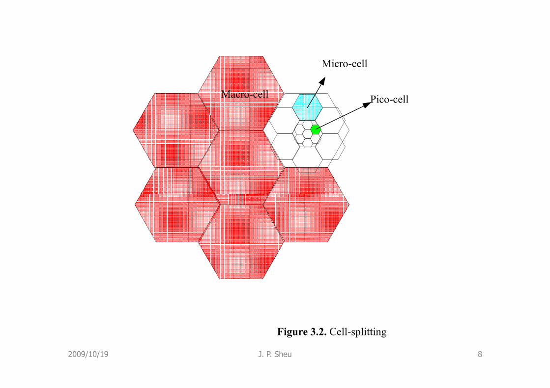
Macro-cell
Micro-cell
Pico-cell
Figure 3.2. Cell-splitting
2009/10/19 J. P. Sheu 8

Sectorization
• Space Division Multiple Access (SDMA)
2009/10/19 J. P. Sheu 9

Channel Allocation Algorithms
• Fixed channel allocation
– Allowed to borrow some channels from neighbors
• Dynamic channel allocation
– Require a centralized arbitrator to allocate channels– Require a centralized arbitrator to allocate channels
• Hybrid channel allocation
– A set of local channels and another set of borrowable
channels
2009/10/19 J. P. Sheu 10

Cellular System Overview
2009/10/19 J. P. Sheu 11

Cellular Systems Terms
• Base Station (BS) – includes an antenna, a controller, and a number of transceivers
• Mobile telecommunications switching office (MTSO) – connects calls between mobile units
• Two types of channels available between mobile unit • Two types of channels available between mobile unit and BS
– Control channels – used to exchange information having to do with setting up and maintaining calls
– Traffic channels – carry voice or data connection between users
2009/10/19 J. P. Sheu 12

Steps in an MTSO Controlled Call
Between Mobile Users
• Mobile unit initialization
– MH scans and select the strongest setup control channel
• Mobile-originated call
– MH sending the called unit on the pre-selected setup channelchannel
• Paging
– The MTSO sends a paging message to certain BSs
• Call accepted
• Ongoing call
• Handoff
2009/10/19 J. P. Sheu 13

2009/10/19 J. P. Sheu 14

Handoff Performance Metrics
• Handoff delay – delay time in the transfer an on-
going call from the current cell to the new cell
• Duration of interruption – the duration of time
during a handoff which is not connected to either BSduring a handoff which is not connected to either BS
• Handoff success probability – probability that a
handoff is successful
• Probability of unnecessary handoff – probability of
the pin-pong effect
2009/10/19 J. P. Sheu 15

Improved Handoff Strategies
• Prioritization: a certain number of channels are reserved for
handoff
• Relative signal Strength: a minimum time for which an MT
must be in a cell before it can request a handoff
• Soft handoffs: a period of time when more than one BS • Soft handoffs: a period of time when more than one BS
handles a call can be allowed
• Predictive handoffs: predict the mobility pattern of mobile
users
• Adaptive handoffs: users may have to be shifted across
different layers, from micro- to macro- cellular
2009/10/19 J. P. Sheu -16
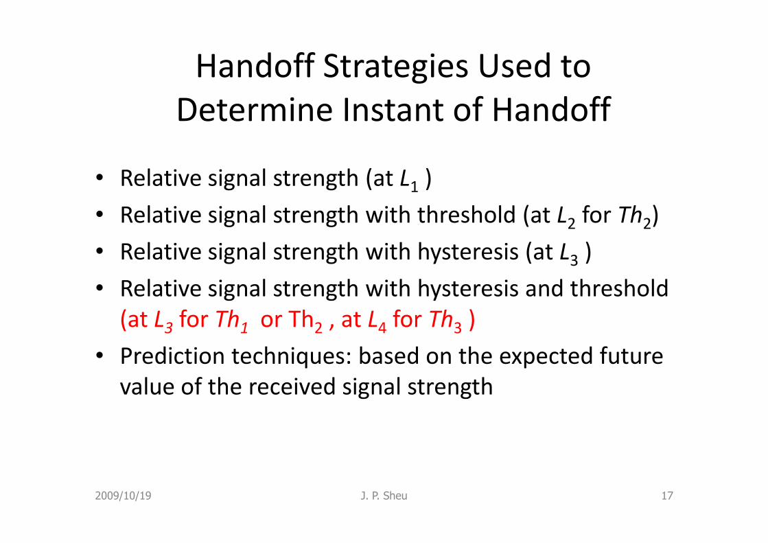
Handoff Strategies Used to
Determine Instant of Handoff
• Relative signal strength (at L1 )
• Relative signal strength with threshold (at L2 for Th2)
• Relative signal strength with hysteresis (at L3 )
• Relative signal strength with hysteresis and threshold
(at L3
for Th1
or Th2 , at L4 for Th3 )
• Prediction techniques: based on the expected future
value of the received signal strength
2009/10/19 J. P. Sheu 17

2009/10/19 J. P. Sheu 18
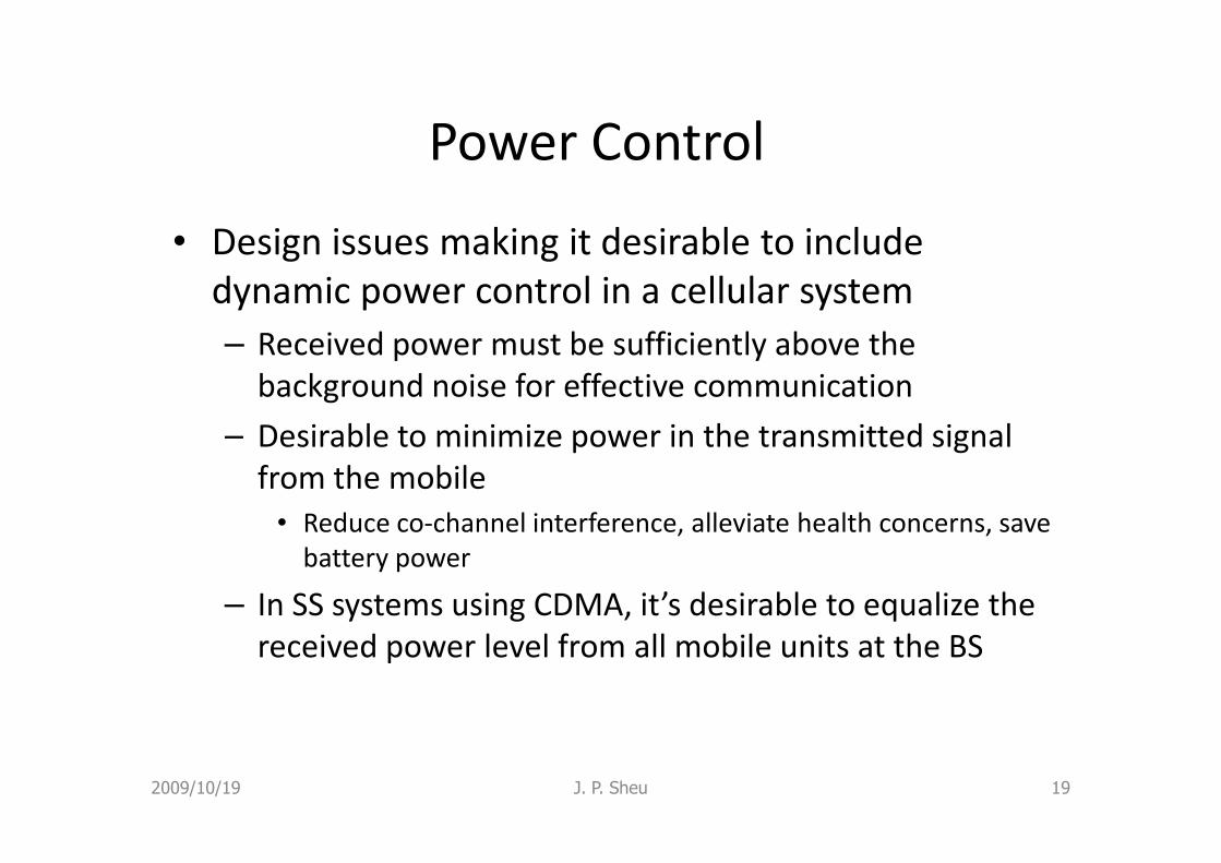
Power Control
• Design issues making it desirable to include
dynamic power control in a cellular system
– Received power must be sufficiently above the
background noise for effective communication
– Desirable to minimize power in the transmitted signal – Desirable to minimize power in the transmitted signal
from the mobile
• Reduce co-channel interference, alleviate health concerns, save
battery power
– In SS systems using CDMA, it’s desirable to equalize the
received power level from all mobile units at the BS
2009/10/19 J. P. Sheu 19

Types of Power Control
• Open-loop power control
– Depends solely on mobile unit
– No feedback from BS
– Not as accurate as closed-loop, but can react quicker to fluctuations in signal strength fluctuations in signal strength
• Closed-loop power control
– Adjusts signal strength in reverse channel based on metric of performance
– BS makes power adjustment decision and communicates to mobile on control channel
2009/10/19 J. P. Sheu 20

2009/10/19 J. P. Sheu 21

First-Generation Analog
• Advanced Mobile Phone Service (AMPS)
– In North America, two 25-MHz bands allocated
to AMPS
• One for transmission from base to mobile unit• One for transmission from base to mobile unit
• One for transmission from mobile unit to base
– Each band split in two to encourage
competition
– Frequency reuse exploited
2009/10/19 J. P. Sheu 22

Differences Between First and
Second Generation Systems
• Digital traffic channels – first-generation systems are almost purely analog; second-generation systems are digital
• Encryption – all second generation systems provide encryption to prevent eavesdropping
• Error detection and correction – second-generation digital traffic allows for detection and correction, giving clear voice reception
• Channel access – second-generation systems allow channels to be dynamically shared by a number of users
2009/10/19 J. P. Sheu 23

Mobile Wireless TDMA Design
Considerations
• Global System for Mobile Communications (GSM)
– Number of logical channels (number of time slots in TDMA frame): 8
– Maximum cell radius (R): 35 km
– Frequency: region around 900 MHz,1800 MHz, or 1900 – Frequency: region around 900 MHz,1800 MHz, or 1900 MHz
– Maximum vehicle speed (Vm
):250 km/hr
– Maximum coding delay: approx. 20 ms
– Maximum delay spread (∆m
): 10 µs (mutipath delay)
– Bandwidth: Not to exceed 200 kHz (25 kHz per channel)
• Maximum data rate for each channel is 34Kbps
2009/10/19 J. P. Sheu 24
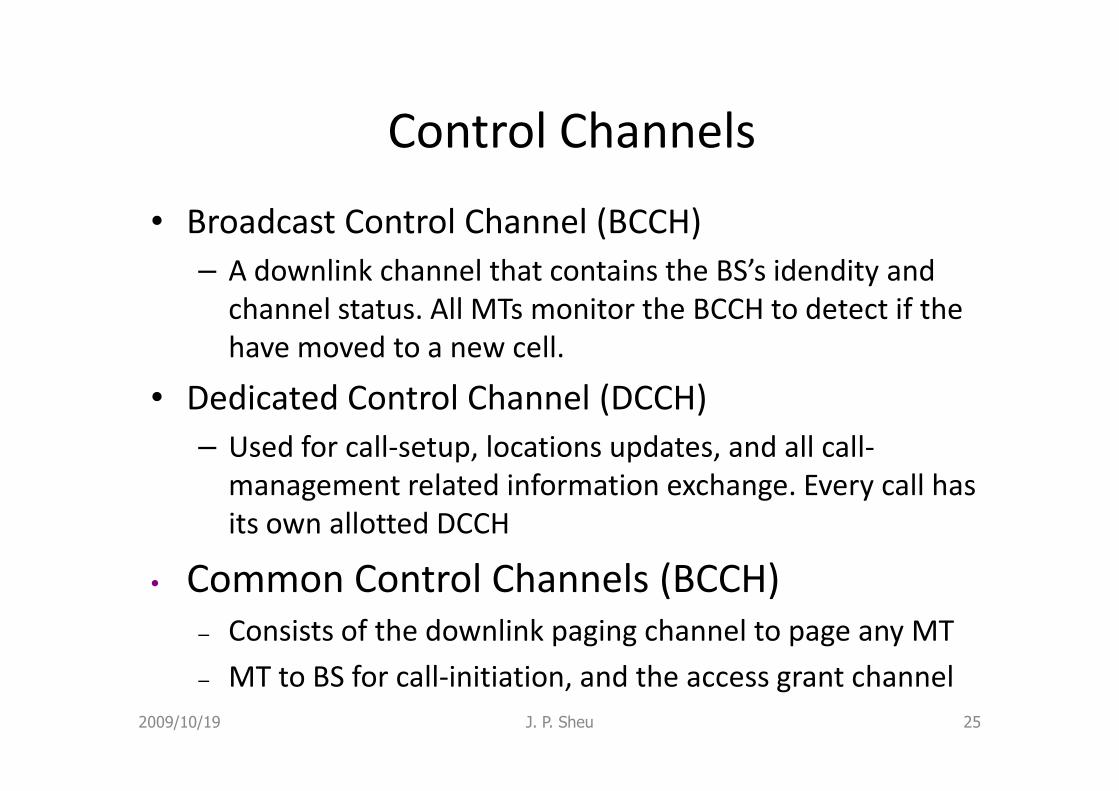
Control Channels
• Broadcast Control Channel (BCCH)
– A downlink channel that contains the BS’s idendity and
channel status. All MTs monitor the BCCH to detect if the
have moved to a new cell.
• Dedicated Control Channel (DCCH)• Dedicated Control Channel (DCCH)
– Used for call-setup, locations updates, and all call-
management related information exchange. Every call has
its own allotted DCCH
• Common Control Channels (BCCH)
– Consists of the downlink paging channel to page any MT
– MT to BS for call-initiation, and the access grant channel
2009/10/19 J. P. Sheu 25

2009/10/19 J. P. Sheu 26

Speech Coding
• Traditional speech coding use pulse code
modulation (PCM)
– The data rate of PCM: 64 kbps
– This rate is undesirably high for use in cellular radio– This rate is undesirably high for use in cellular radio
• With current technology, 12kbps is enough
– Due to the maximum coding delay is 20 ms it is
reasonable to form the encoded speech into blocks of
20 ms duration, or speech samples of 240 bits
2009/10/19 J. P. Sheu 27

ITU’s View of Third-Generation
Capabilities
• Voice quality comparable to the public switched telephone network
• 144 kbps data rate available to users in high-speed motor vehicles over large areas
• 384 kbps available to pedestrians standing or • 384 kbps available to pedestrians standing or moving slowly over small areas
• Support for 2.048 Mbps for office use
• Symmetrical / asymmetrical data transmission rates
• Support for both packet switched and circuit switched data services
2009/10/19 J. P. Sheu 28

ITU’s View of Third-Generation
Capabilities (IMT 2000)
• An adaptive interface to the Internet to reflect
efficiently the common asymmetry between
inbound and outbound traffic
• More efficient use of the available spectrum in • More efficient use of the available spectrum in
general
• Support for a wide variety of mobile equipment
• Flexibility to allow the introduction of new
services and technologies
2009/10/19 J. P. Sheu 29

Table 3.1. Evolution plan to 3G standards
Country Existing 2G
Standard
3G Standard
Europe GSM W-CDMA Europe GSM W-CDMA
(UMTS)
Japan PDC W-CDMA
(DoCoMo)
USA IS-95 / cdma one Cdma2000
USA IS-136 UWC-136
2009/10/19 J. P. Sheu 30

Table 3.2. IMT-2000 Service Types
Service Upstream Downstrea
m
Example Switching
Interactive
Multimedia
256 Kbps 256 Kbps Video
conference
Circuit
High
Multimedia
20 Kbps 2 Mbps TV Packet
Multimedia
Medium
Multimedia
19.2 Kbps 768 Kbps Web
surfing
Packet
Switched
Data
43.2 Kbps 43.2 Kbps Fax Circuit
Simple
Messaging
28.8 Kbps 28.8 Kbps E-mail Packet
Speech 28.8 Kbps 28.8 Kbps Telephony Circuit
2009/10/19 J. P. Sheu 31

The Problems with 3G Systems
• Difficult to find a common slice of spectrum to
enable global roaming
• Disappointing performance of CDMA in
practicepractice
• It is hard to find suitable applications
2009/10/19 J. P. Sheu 32

Claims Reality
Capacity of 20 times that of
AMPS
Only 3-4 times that of AMPS
Table 3.3 CDMA – The debate
AMPS
No more dropped calls
No problem of interference
Quality if speech promised at 8
Kbps
40 percent dropped calls when
loaded
Interference from existing AMPS
Had to change to 13 Kbps
2009/10/19 J. P. Sheu 33

Wireless in Local Loop
• Local loop: the last hop connectivity between
the subscriber and PSTN
• Advantages:
– Easy deployment, high scalability– Easy deployment, high scalability
– Low investment cost, cost effective
2009/10/19 J. P. Sheu 34

FSU
Telephone
FSU
Telephone
FSU
Telephone
Figure 3.6. WLL architecture
2009/10/19 J. P. Sheu 35
BTS

IEEE 802.16 Standard
• Metropolitan area networks (MANs) span several km and cover large parts of cities
• MANs much larger in size than LANs and their functionalities differ from those LANsfunctionalities differ from those LANs
• IEEE 802.16 is called air interface for fixed broadband wireless access systems
– Based on OSI model, specifies air interface including data link layer and physical layer
2009/10/19 J. P. Sheu 36

Differences between 802.11 and
802.16
• IEEE 802.16 was designed for broadband data
such as digital video and telephony
• The number of users and BW usage per user is
much higher than IEEE 802.11much higher than IEEE 802.11
• IEEE 802.16 is completely connection-oriented
and QoS guarantees
2009/10/19 J. P. Sheu 37

Physical Layer
• Uses traditional narrow-band radio (10-66 GHz) with conventional modulation scheme
• Two new protocols attempt to close to IEEE 802.11– 802.16a operates in the 2 – 11 GHz and 802.16b operates in
5 GHz ISM band
• Since the signal strength falls off sharply with distance • Since the signal strength falls off sharply with distance from the BS, the following three modulation scheme are used– QAM-64 used by subscribers located near the BS
– QAM-16 used by subscribers located at intermediate distance from the BS
– QPSK used by subscribers located far away from the BS
2009/10/19 J. P. Sheu 38

Data Link Layer
• DLL of IEEE 802.16 can be subdivided into
three sublayers
– Security sublayer: only the payloads are encrypted
– MAC sublayer: deals with channel management – MAC sublayer: deals with channel management
and slot allocation to stations
– Services specific convergence sublayer: interface
to the network layer
2009/10/19 J. P. Sheu 39

MAC Sublayer
– On the downlink, data to the SS is TDM and on
the uplink, the medium is shared by the SSs
using TDMA
– Each uplink connection has four classes of – Each uplink connection has four classes of
services:
• Constant bit rate service (voice)
• Real-time variable bit rate service (multimedia)
• Non-real-time variable bit rate service (file transfer)
• Best effort service (others)
2009/10/19 J. P. Sheu 40

Table 3.4. A brief comparison among IEEE 802.11b WLANs,
IEEE 802.16 WMANs, and GSM WWANs
Feature IEEE 802.11B
WLANs
IEEE 802.16 WMANs GSM WWANs
Range Few hundred meters Several Km Few tens of Km
Frequency 2.4 GHz ISM band 10-66 GHz 900 or 1800 MHz
Physical Layer CCK, BPSK, QPSK QAM-64, QAM16,
QPSK
GMSK
Maximum Data Rates 11 Mbps 60–180 Mbps 9.6 Kbps/userMaximum Data Rates 11 Mbps 60–180 Mbps 9.6 Kbps/user
Medium Access CSMA/CA TDM/TDMA FDD/TDMA
QoS Support DCF-No
PCF-Yes
Yes Yes
Connectivity DCF-connectionless
PCF-connection
oriented
Connection oriented Connection oriented
Typical Applications Web browsing, e-mail Multimedia, digital
TV broadcasting
Voice
2009/10/19 J. P. Sheu 41

Homework
• 3, 4, 9
2009/10/19 J. P. Sheu 42