Wireless PC-Peripherals Communication via Blue Tooth (D0130 project)
19
Communication Communication via via Blue Tooth Blue Tooth (D0130 project) (D0130 project) Zaher Andrawis Zaher Andrawis Ashraf khoury Ashraf khoury Intermediate Report Intermediate Report Supervisor Hain Brodny Summer 2001
-
Upload
hollie-little -
Category
Documents
-
view
215 -
download
1
Transcript of Wireless PC-Peripherals Communication via Blue Tooth (D0130 project)

Wireless PC-Peripherals Wireless PC-Peripherals
CommunicationCommunication
viavia
Blue ToothBlue Tooth(D0130 project)(D0130 project)
Zaher Andrawis Zaher Andrawis
Ashraf khouryAshraf khoury
Intermediate ReportIntermediate ReportSupervisor
Hain BrodnySummer 2001
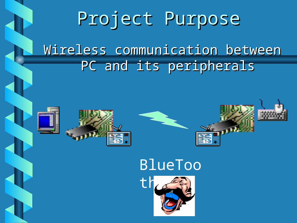
Project PurposeProject Purpose
Wireless communication between PC Wireless communication between PC and its peripheralsand its peripherals
BlueTooth

SpecificationsSpecifications• Communication between PC and a Communication between PC and a
peripheral device through the peripheral device through the McBSP serial port of the DSPMcBSP serial port of the DSP
• Translating the PS/2 protocol from Translating the PS/2 protocol from the PC or Device side to the the PC or Device side to the McBSP. The DSP transfers McBSP. The DSP transfers transparently the received bytestransparently the received bytes
Implementation:Implementation:
FPGA board with PS/2 connectors FPGA board with PS/2 connectors and a connection to DSPand a connection to DSP
DSP program to mirror the dataDSP program to mirror the data

Specifications Specifications (cont)(cont)
• Board requirements:Board requirements: FPGA FLEX10K100 BoardFPGA FLEX10K100 Board EPC2 configuration chip and Jtag InterfaceEPC2 configuration chip and Jtag Interface 4 PS/2 Connectors 4 PS/2 Connectors An interface to 5402 DSPAn interface to 5402 DSP Debugging pinsDebugging pins Jumpers to enable “McBSP” In/OutJumpers to enable “McBSP” In/Out “ “contact” to work-around the DSP!contact” to work-around the DSP! Power SupplyPower Supply
• We aim to check the system “due We aim to check the system “due diligence”, thus voltage and power diligence”, thus voltage and power adjustment of the final “tape-out” less adjustment of the final “tape-out” less concerns usconcerns us

Specifications Specifications (cont)(cont)• FPGA implementation should include 10KHZ FPGA implementation should include 10KHZ
PS/2 protocol, and McBSP protocol in the PS/2 protocol, and McBSP protocol in the DSP frquency we’ll configure in the future.DSP frquency we’ll configure in the future.
• Testing will be done by defining the Testing will be done by defining the appropriate test-benches in Renoir, And by appropriate test-benches in Renoir, And by DSP software…DSP software…
• Equipment requirements:Equipment requirements: PC (with LPT + 2 serial ports!)PC (with LPT + 2 serial ports!) PS/2 device (keyboard + mouse)PS/2 device (keyboard + mouse) DSK (of DSP 5402)DSK (of DSP 5402) ByteBlaster parallel portByteBlaster parallel port Digital “scope” for debuggingDigital “scope” for debugging JumpersJumpers Vcc/GND supplierVcc/GND supplier (Vcc=5 v !) (Vcc=5 v !)

BackgroundBackground• Input/Output:Input/Output:
PS/2 : 10KHZ – PS/2 : 10KHZ – Start/Data(8)/Stop/Parity Start/Data(8)/Stop/Parity bits…bits…
(http://panda.cs.ndsu.nodak.edu/~achapwes/PICmicro/PS2/ps2.htm)
PC and Device cannot collide in PC and Device cannot collide in transmitting/receiving… BUT : Using the transmitting/receiving… BUT : Using the wireless broadcast might cause such a wireless broadcast might cause such a collision collision The FPGA implementation The FPGA implementation handles that!handles that!

McBSPMcBSP of DSP: Typically 12.5 MHz of DSP: Typically 12.5 MHzThe exact frequency is determined by the clock The exact frequency is determined by the clock
generating method, configured using the McBSP generating method, configured using the McBSP control registers.control registers.

Functional BlocksFunctional Blocks
PS/2 lines
McBSP lines
PS/2 Interface McBSP
InterfaceController
DeviceSide
DeviceSide=1
PCDeviceSide=0 Mouse
DSPDeviceSide=1 DeviceSide=0 Keyboard

Hardware – The whole Hardware – The whole SystemSystem

Hardware – FPGA BoardHardware – FPGA Board
FPGA Board
PS/2 connector
PS/2 connector
PS/2 connector
PS/2 connector
FPGAfor
PCfor
Devices
Jumpers for McBSP “contact”DSP Interface
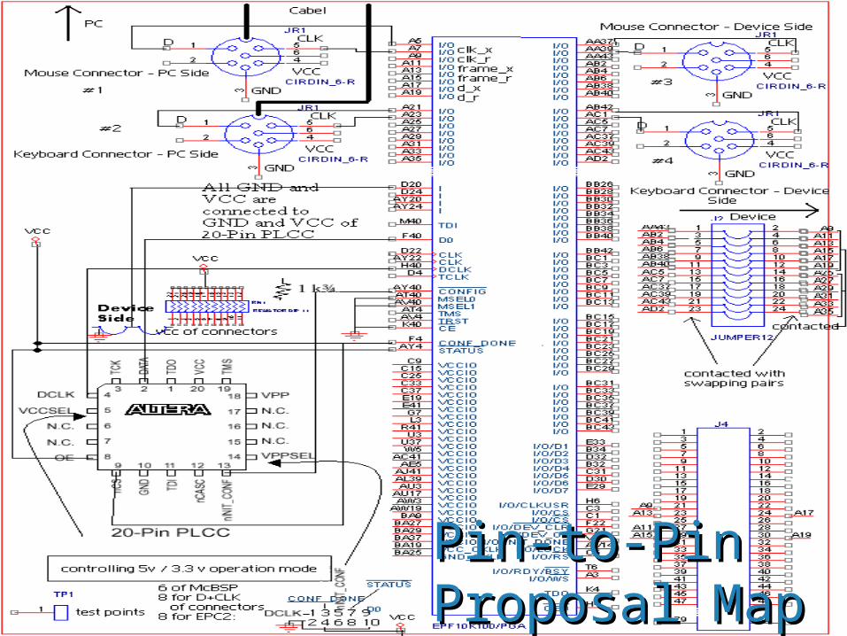
Pin-to-Pin Pin-to-Pin Proposal MapProposal Map

FPGA of ALTERAFPGA of ALTERA
• FLEX10K100:FLEX10K100: Supports Peripheral connectionSupports Peripheral connection10 MHz clock10 MHz clockRelevant Configuration Device is Relevant Configuration Device is EPC2, or EPC2, or
2 EPC1s ! 2 EPC1s ! For the moment we’ve designed For the moment we’ve designed the system for one EPC2the system for one EPC2..
Dev’ Software: Renoir 2000 Dev’ Software: Renoir 2000 ModelSem+Leonardo, MaxPlusIIModelSem+Leonardo, MaxPlusII

Translation Blocks Translation Blocks in a nutshellin a nutshell
Compiles Hierarchaly with 0 Errors!
FRFX
CLKR
CLKX
DRDX

Main ControllerMain Controller• 2 FSMs for controlling PS/2 and 2 FSMs for controlling PS/2 and
McBSP units, and samples their McBSP units, and samples their statusstatus
• Handles Collision (possible !!)Handles Collision (possible !!)

Interface – Example: PS/2Interface – Example: PS/2
Reminder

Interface – Example: PS/2 Interface – Example: PS/2 (cont)(cont)
Reminder

SoftwareSoftware• In part A we are requested to In part A we are requested to
“work-around” the BT:“work-around” the BT: Translate PS/2 to McBSP and vise Translate PS/2 to McBSP and vise
versaversa DSP mirros the input to the outputDSP mirros the input to the output::
• We assume the McBSP API is We assume the McBSP API is ready…ready…
• While(TRUE){While(TRUE){
a = getchar(A1)a = getchar(A1)
putchar(A2)putchar(A2)
}}

Software / TestingSoftware / Testing• The above program tests the PS/2-The above program tests the PS/2-
to-McBSP-McBSP-to-PS/2 !to-McBSP-McBSP-to-PS/2 !
• Alternative testing for the McBSP only Alternative testing for the McBSP only is :is :
OnceInAWhile(){OnceInAWhile(){
putchar(a,A2);putchar(a,A2);
a’=getchar(A1);a’=getchar(A1);
““Shout()” if a’!=aShout()” if a’!=a
}}

ScheduleSchedule• 30.830.8 (this week)– Finish pin-to- pin (this week)– Finish pin-to- pin
scheme and send board for start-up…scheme and send board for start-up…
• 6.9 6.9 (next week)– Finish test benches, (next week)– Finish test benches, with successfully working Renoir moduleswith successfully working Renoir modules
• 13.9 13.9 –Controlling/understanding DSP –Controlling/understanding DSP software and building the required tests.software and building the required tests.
• 13.10 13.10 – Testing the ready (hopefully!) – Testing the ready (hopefully!) FPGA board:FPGA board:
We should type a char in the keyboard, or move the We should type a char in the keyboard, or move the mouse, and see the effect on the connected PC, mouse, and see the effect on the connected PC, when data goes through our FPGA + DSP !when data goes through our FPGA + DSP !