Wheel Alig ment - URLbiblio3.url.edu.gt/Libros/2012/Wheel-Alignment.pdf · Wheel Alig ment 2011...
20
Wheel Alig ment 2011 Automobile Maintenance Advanced Course for the Industrial Technical Instructors No. : ---------- Name: --------- Instructor: Li,Kai-Shiung 2011/11/02
Transcript of Wheel Alig ment - URLbiblio3.url.edu.gt/Libros/2012/Wheel-Alignment.pdf · Wheel Alig ment 2011...

Wheel Alig ment
2011 Automobile
Maintenance Advanced
Course for the Industrial
Technical Instructors
No. : ----------
Name: ---------Instructor: Li,Kai-Shiung
2011/11/01~ 2011/11/02

~~-'--"---------~- -~---- .--~~-. ------~------------
Wheel Alignment 2011 Automobile Maintenance Advanced Course for
the Industrial Technical Instructors
Instructor: Li,Kai-Shiung
2011111101~2011111102
Abstract
A. Six items for wheel alignment
B. Other factors to influence wheel alignment

Introduction
Inaccurate wheel alignment can cause:
CD difficult steering
® poor steering stability
® poor reciprocation on hairpin comer
@ shorten the tire life span
... etc.
Six items for wheel alignment
1. ~ ~ ~ li (Suspension Height)
2.9r1tJt ~ (Camber)
3. 0J 1tJt ~ (Steering-axis Inclination' SAl)
or (King Pin Inclination ' KPI)
4 .ft 1tJt ~ (Caster)
5.m- -*- (Toe in)
6.J@~ -f1~ (Turning Radius)
2

1. ~ ~ ~ Ii (Suspension Height)
* The distance between the vehicle body, frame or any suspension point to the ground.
5
Suspension Height
3

---~--~-------------~------
2. 91' 1~Jt ~ (Camber)
* The angle between the center line of the wheel viewed from the front and the vertical axis used for steering.
1. The center line of the wheel inclines outward is called positive camber.
2. Overlapping center line of the wheel and the vertical axis is called zero camber.
3. The center line of the wheel inclines inward is called negative camber.
*camber is normally be,tween - 1.5 0 ~ + 1.5 0
camber
Camber
4

· ------------ ------,
spindle
o-__ ~
Force on spindle
Non-slip force for wheels
5

-----~-- -- .-~~ --_. ---- ------~~------~
Turning radius of the tire
3.** fuJ -,Th pq 1t~ ~ (~*£~* JXJ 1t~ ~ ) ( Steering-axis Inclination ' SAl) or (King Pin Inclination ' KPI)
* The angle between vertical axis and King Pin center line or steering axle center line viewed from the front usually falls between 6 0 ~ 9 0
•
12
6

----- - ---_._----_ .. _ .. _-----_._--- ---------- --- --
King Pin centerline
SAl
~~~~~~ ~ (a~ King Pin Type I (hi Double-Wishbone Type
( King Pin Inclination ' KPI) (Steering-axis Inclination ' SAl)
~ z. ~ (Included Angle)
*The sum of KPI and camber is called Included Angle. The cross point is under the ground(positive steering offset). It makes steering easier and tires more durable.
* Incorrect included angle indicates steering column or spindle are twisted.
~ the included angles of left and right wheels should be equal, or it means the parts are distorted.
* Different contact position of included angle vertex and the ground will affect its tendency to roll inward or outward.
14
1

Wheel centerline
Included Angle
Ball Joint
Included Angle
4 -1t 1~Ji f!j (Caster)
"* The angle between the vertical axis and King Pin centerline or steering axle centerline viewed from the side.
"* Incline backward is called positive caster, incline frontward is called negative caster. Normally caster falls between - 1 0 ,-....., + 3 0 for ordinary vehicles.
"*The distance between the cross point of steering axle centerline and the ground to the contact surface center of the tire and ground is called backward inclination drag distance.
8
- I

- - - --------- - ---- ---- ---- ---- ---- ------- ,
I Steering axle I
tire
Contact surface
Caster
Vertical axis
~ front
Tire centerline
Guiding center I
Straight driving guidance of positive caster
9

--~-------~
front
Q Q'
Positive backward inclination drag distance assist in steering reciprocation
~ + Standard caster I rear
~ wl!J= Suspension level
+ I Bigger caster
+ Smaller caster
l~ sm Influence of different suspension level
10

-------------------------_._--
5.m ~ (Toe in)
*Viewed from the top, if the distance between front part of the two wheels is smaller than the rear part of the two wheels is called Toe in.
* The unit for toe in can be represented by distance or degree, and distance (mm) is more commonly used.
*when the distance between front part of the two wheels is bigger than the rear part of the two wheels is called Toe out.
21
front t
A
B
Toe in
11
~~~- -- ._------. ~~-.---.-------- -------,
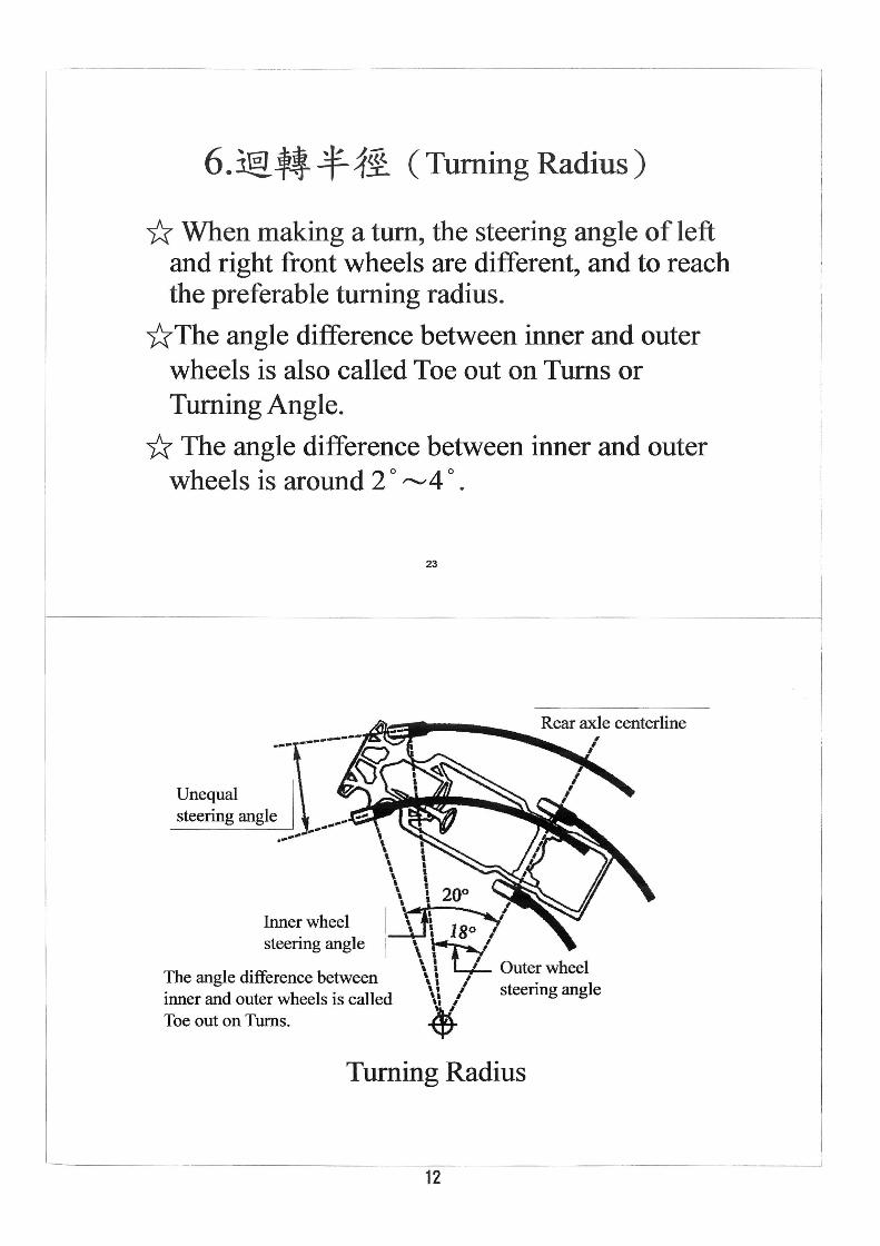
6. 3@ tt- -f 1it (Turning Radius)
* When making a tum, the steering angle of left and right front wheels are different, and to reach the preferable turning radius.
*The angle difference between inner and outer wheels is also called Toe out on Turns or Turning Angle.
* The angle difference between inner and outer wheels is around 2 0 ~4 0 •
.--Unequal steering angle
23
.ASlI .. __ ..... ~Rear axle centerline
\ \ \ , " ' \ \ 20°
Inner wheel '\1\ 1 ;::-;l steering angle ' \fi'
\ I ,
\ \ I Outer wheel The angle difference between \ \ I . I inner and outer wheels is called \ \ I steenng ang e
~' Toe out on Turns. '17
Turning Radius
12

-----.---
~ar Jt I. -'* M JJi JI! Ackermann steering geometry
CDwhen making a tum, centerlines of each wheel will intersect to one point, and the tum can be smooth if taking this point as a circle center. (2)when making a tum, the angle of front inner wheel is bigger than front outer wheel due to wheel distance and wheelbase.
---_._-----,
Other factors to influence wheel alignment
1. tt. fuJ 1,ta 1ft (Steering Offset)
or (Scrub Radius)
2.,wlfE1:. (Setback)
3.41fh flJ &. (ThrustAngle)
13

-------- ----- ---------- --_._ -
tl fuJ 1'1ft (Steering Offset) ~tmf% f-1~ (Scrub Radius)
*The distance of the cross point of King pin or Steering axis centerline with ground to the cross point of wheel centerline with ground is called steering offset.
--* If the cross point of steering axis centerline with ground is at the inside of cross point of wheel centerline with ground then steering offset is positive.
--* If the cross point is at outside then steering offset is negative.
--* If they cross on same spot on ground then steering offset is zero.
o 27
inclination
lNheel Centerline
Negative Steering Offset
14

, (/'" \r:\ \( .
1m llE 1: (Setback)
U When the wheelbase of two sides of the vehicle are different, it is called setback.
~ When right wheelbase is smaller than left wheelbase, it is called positive setback
~ When right wheelbase is bigger than left wheelbase, it is called negative setback
29
1__ I short wheelbase "'1
I) ~ )
Front I ¢ I Setback
~ ) -. f.-I-
n 4"
I.. Long wheelbase I "'1
Setback (Positive setback)
15

-------------~~~~~~---~~--~~~-----------------,
~it fJ ~ Ji (Thrust Angle)
* When four wheels are correctly positioned, the vehicle can run straight steadily. * When rear wheels are incorrectly positioned or the setback is too big, the vehicle might deviate.
The moving direction depends on Vehicle Centerline, Geometric Centerline and Thrust Line. * F or FR type vehicles, incorrect rear axle position or damaged chassis will generate thrust angle. * F or vehicles with rear wheel independent suspension system, it can also generate thrust angle when there is uneven toe in adjustment for rear wheels, causing rapid wear and tear ofthe3tires.
I centerline
I I
Thrust line
Thrust Angle
{a)1 FR Vehicle I
i~rl I Front ¢ -++---1 --+--..-,~--
_---o-r---/' --~: 11 --~~~~==~~~~~
I Thrust line I (b~ Independent rear suspension
Thrust Angle
16

~-----.-------------.-------.--------.--
Conclusion * As the growing development of vehicle suspension
and steering system structure, the demand for wheel alignment angle is getting stronger. * Wheel alignment equipment is not for adjusting or changing alignment angle but a reference for mechanics. Mechanics compared the original angle with measured angle. If it exceeds tolerable range then they may adjust or replace the parts for keeping it at original angle. * Advanced equipments required experienced and skilled mechanics.
33
7j<ZP*,rEl (Level bubble)
~1tJflJ
9f.MflJ (Camber)
I (Caster)
Bubble meter
17
pqmflJ (KPI/SAI) I

---- -- ----~~------~-----~.--. ~--- -----------~----------,
bubble meter
I Turn table base
I Turntable
Turntable
Bubble Meter Operation
1. Place the two front wheels on the turntable. Lift the two rear wheels to the same level as front wheels.
2.Reset the level bubble to zero
--+Read Camber
3.Pull out the turntable pin
4. Reset the Caster to zero by adjustment screw
5.Turn 20° outward
--+ Read Caster
6. Reset the KPI to zero by adjustment screw
7. Tum 400
inward
--+ Read KPI ISAI
Camber
--+Check the turning angle of the other front wheel.
36
18
Level bubble
Caster
KPIISAI

Wheel Alignment Work Sheet
2011 Automobile Maintenance Advanced Course for the Industrial Technical Instructors
No.: lAO<=\.
Name:
Instructor: Li,Kai-Shiung
Vehicle type : ___ f
\ 0',0 ~; , ! ':'~I -
-t,.JvO ' .
Item Alignment Measurement
Left : Right:
01 Camber .--4., (, ~ o. j"
Left : Right:
02 KPI/SAI \ / Camber '. '-~, I 3
Left : Right:
03 Caster -z. -1--Z , 5'
Left : Right: I ' ~ ,-- !
04 Toe out on Turns ,.-, cf '" -Z [ ,
Vehicle type :
Adjustment Item Alignment
Before After
01 Toe in
19
Level bubble
Caster
KPII SAl