What’s New in CADDS 5i Release 14 - john-j-jacobs.de and ISOGEN are ... Microsoft Project,...
60
Parametric Technology Corporation What’s New in CADDS ® 5i Release 14 CADDS® 5i Release 14 DOC40175-012
-
Upload
truongnguyet -
Category
Documents
-
view
229 -
download
2
Transcript of What’s New in CADDS 5i Release 14 - john-j-jacobs.de and ISOGEN are ... Microsoft Project,...

Parametric Technology Corporation
What’s New in
CADDS® 5i Release 14
CADDS® 5i Release 14
DOC40175-012

Copyright © 2005 Parametric Technology Corporation. All Rights Reserved.User and training documentation from Parametric Technology Corporation (PTC) is subject to the copyright lawsof the United States and other countries and is provided under a license agreement that restricts copying,disclosure, and use of such documentation. PTC hereby grants to the licensed user the right to make copies inprinted form of this documentation if provided on software media, but only for internal/personal use and inaccordance with the license agreement under which the applicable software is licensed. Any copy made shallinclude the PTC copyright notice and any other proprietary notice provided by PTC. This documentation may notbe disclosed, transferred, modified, or reduced to any form, including electronic media, or transmitted or madepublicly available by any means without the prior written consent of PTC and no authorization is granted to makecopies for such purposes.
Information described herein is furnished for general information only, is subject to change without notice, andshould not be construed as a warranty or commitment by PTC. PTC assumes no responsibility or liability for anyerrors or inaccuracies that may appear in this document.
The software described in this document is provided under written license agreement, contains valuable tradesecrets and proprietary information, and is protected by the copyright laws of the United States and othercountries. It may not be copied or distributed in any form or medium, disclosed to third parties, or used in anymanner not provided for in the software licenses agreement except with written prior approval from PTC.UNAUTHORIZED USE OF SOFTWARE OR ITS DOCUMENTATION CAN RESULT IN CIVIL DAMAGES ANDCRIMINAL PROSECUTION.
Registered Trademarks of Parametric Technology Corporation or a SubsidiaryAdvanced Surface Design, Behavioral Modeling, CADDS, Computervision, CounterPart,Create • Collaborate • Control, EPD, EPD.Connect, Expert Machinist, Flexible Engineering, GRANITE,HARNESSDESIGN, Info*Engine, InPart, MECHANICA, Optegra, Parametric Technology,Parametric Technology Corporation, PartSpeak, PHOTORENDER, Pro/DESKTOP, Pro/E, Pro/ENGINEER,Pro/HELP, Pro/INTRALINK, Pro/MECHANICA, Pro/TOOLKIT, Product First,Product Development Means Business, Product Makes the Company, PTC, the PTC logo, PT/Products,Shaping Innovation, Simple • Powerful • Connected, The Way to Product First, and Windchill.
Trademarks of Parametric Technology Corporation or a Subsidiary3DPAINT, Associative Topology Bus, AutobuildZ, CDRS, CV, CVact, CVaec, CVdesign, CV-DORS, CVMAC,CVNC, CVToolmaker, EDAcompare, EDAconduit, DataDoctor, DesignSuite, DIMENSION III,Distributed Services Manger, DIVISION, e/ENGINEER, eNC Explorer, Expert Framework, Expert MoldBase,Expert Toolmaker, FlexPDM, FlexPLM, Harmony, InterComm, InterComm Expert, InterComm EDAcompare,InterComm EDAconduit, ISSM, KDiP, Knowledge Discipline in Practice, Knowledge System Driver, ModelCHECK,MoldShop, NC Builder, POLYCAPP, Pro/ANIMATE, Pro/ASSEMBLY, Pro/CABLING, Pro/CASTING, Pro/CDT,Pro/CMM, Pro/COLLABORATE, Pro/COMPOSITE, Pro/CONCEPT, Pro/CONVERT, Pro/DATA for PDGS,Pro/DESIGNER, Pro/DETAIL, Pro/DIAGRAM, Pro/DIEFACE, Pro/DRAW, Pro/ECAD, Pro/ENGINE,Pro/FEATURE, Pro/FEM-POST, Pro/FICIENCY, Pro/FLY-THROUGH, Pro/HARNESS, Pro/INTERFACE,Pro/LANGUAGE, Pro/LEGACY, Pro/LIBRARYACCESS, Pro/MESH, Pro/Model.View, Pro/MOLDESIGN,Pro/NC-ADVANCED, Pro/NC-CHECK, Pro/NC-MILL, Pro/NC-POST, Pro/NC-SHEETMETAL, Pro/NC-TURN,Pro/NC-WEDM, Pro/NC-Wire EDM, Pro/NETWORK ANIMATOR, Pro/NOTEBOOK, Pro/PDM,Pro/PHOTORENDER, Pro/PIPING, Pro/PLASTIC ADVISOR, Pro/PLOT, Pro/POWER DESIGN, Pro/PROCESS,Pro/REPORT, Pro/REVIEW, Pro/SCAN-TOOLS, Pro/SHEETMETAL, Pro/SURFACE, Pro/VERIFY, Pro/Web.Link,Pro/Web.Publish, Pro/WELDING, ProductView, PTC Precision, Routed Systems Designer, Shrinkwrap,The Product Development Company, Validation Manager, Wildfire, Windchill DynamicDesignLink,Windchill PartsLink, Windchill PDMLink, Windchill ProjectLink, and Windchill SupplyLink.
Patents of Parametric Technology Corporation or a SubsidiaryRegistration numbers and issue dates follow. Additionally, equivalent patents may be issued or pending outside ofthe United States. Contact PTC for further information.
GB2366639B 13-October-2004 GB2353376 05-November-2003 5,140,321 18-August-1992GB2363208 25-August-2004 GB2354686 15-October-2003 5,423,023 05-June-1990(EP/DE/GB)0812447 26-May-2004 6,545,671 B1 08-April-2003 4,310,615 21-December-1998GB2365567 10-March-2004 GB2354685B 18-June-2003 4,310,614 30-April-1996
Third-Party TrademarksAdobe, Acrobat, Distiller, and the Acrobat logo are trademarks of Adobe Systems Incorporated.Advanced ClusterProven, ClusterProven, and the ClusterProven design are trademarks or registered trademarksof International Business Machines Corporation in the United States and other countries and are used underlicense. IBM Corporation does not warrant and is not responsible for the operation of this software product. AIX isa registered trademark of IBM Corporation. Allegro, Cadence, and Concept are registered trademarks of CadenceDesign Systems, Inc. Apple, Mac, Mac OS, and Panther are trademarks or registered trademarks of AppleComputer, Inc. AutoCAD and Autodesk Inventor are registered trademarks of Autodesk, Inc. Baan is a registeredtrademark of Baan Company. CADAM and CATIA are registered trademarks of Dassault Systemes. COACH is atrademark of CADTRAIN, Inc. CYA, iArchive, HOTbackup, and Virtual StandBy are trademarks or registeredtrademarks of CYA Technologies, Inc. DOORS is a registered trademark of Telelogic AB. FLEXlm and FLEXnetare registered trademarks of Macrovision Corporation. Geomagic is a registered trademark of RaindropGeomagic, Inc. EVERSYNC, GROOVE, GROOVEFEST, GROOVE.NET, GROOVE NETWORKS, iGROOVE,PEERWARE, and the interlocking circles logo are trademarks of Groove Networks, Inc. Helix is a trademark ofMicrocadam, Inc. HOOPS is a trademark of Tech Soft America, Inc. HP-UX is a registered trademark ofHewlett-Packard Company. I-DEAS, Metaphase, Parasolid, SHERPA, Solid Edge, TeamCenter, UG-NX, andUnigraphics are trademarks or registered trademarks of UGS Corp. InstallShield is a registered trademark andservice mark of InstallShield Software Corporation in the United States and/or other countries. Intel is a registeredtrademark of Intel Corporation. IRIX is a registered trademark of Silicon Graphics, Inc. I-Run and ISOGEN areregistered trademarks of Alias Ltd. LINUX is a registered trademark of Linus Torvalds. MainWin and Mainsoft aretrademarks of Mainsoft Corporation. MatrixOne is a trademark of MatrixOne, Inc. Mentor Graphics andBoard Station are registered trademarks and 3D Design, AMPLE, and Design Manager are trademarks ofMentor Graphics Corporation. MEDUSA and STHENO are trademarks of CAD Schroer GmbH. Microsoft,Microsoft Project, Windows, the Windows logo, Windows NT, Windows XP, Visual Basic, and the Visual Basiclogo are registered trademarks of Microsoft Corporation in the United States and/or other countries. Moldflow is aregistered trademark of Moldflow Corporation. Netscape and the Netscape N and Ship’s Wheel logos areregistered trademarks of Netscape Communications Corporation in the U.S. and other countries. Oracle is aregistered trademark of Oracle Corporation. OrbixWeb is a registered trademark of IONA Technologies PLC.PDGS is a registered trademark of Ford Motor Company. RAND is a trademark of RAND Worldwide.Rational Rose is a registered trademark of Rational Software Corporation. RetrievalWare is a registeredtrademark of Convera Corporation. RosettaNet is a trademark and Partner Interface Process and PIP areregistered trademarks of RosettaNet, a nonprofit organization. SAP and R/3 are registered trademarks of SAP AGGermany. SolidWorks is a registered trademark of SolidWorks Corporation. All SPARC trademarks are usedunder license and are trademarks or registered trademarks of SPARC International, Inc. in the United States andin other countries. Products bearing SPARC trademarks are based upon an architecture developed by SunMicrosystems, Inc. Sun, Sun Microsystems, the Sun logo, Solaris, UltraSPARC, Java and all Java based marks,and "The Network is the Computer" are trademarks or registered trademarks of Sun Microsystems, Inc. in theUnited States and in other countries. 3Dconnexion is a registered trademark of Logitech International S.A. TIBCOis a registered trademark and TIBCO ActiveEnterprise, TIBCO Designer, TIBCO Enterprise Message Service,TIBCO Rendezvous, TIBCO TurboXML, and TIBCO BusinessWorks are the trademarks or registered trademarksof TIBCO Software Inc. in the United States and other countries. WebEx is a trademark of WebExCommunications, Inc.
Third-Party Technology InformationCertain PTC software products contain licensed third-party technology:
Rational Rose 2000E is copyrighted software of Rational Software Corporation.
(GB)2388003B 21-January-2004 GB2354683B 04-June-2003 4,310,614 22-April-19996,665,569 B1 16-December-2003 6,608,623 B1 19-August-2003 5,297,053 22-March-1994GB2353115 10-December-2003 6,473,673 B1 29-October-2002 5,513,316 30-April-19966,625,607 B1 23-September-2003 GB2354683B 04-June-2003 5,689,711 18-November-19976,580,428 B1 17-June-2003 6,447,223 B1 10-September-2002 5,506,950 09-April-1996GB2354684B 02-July-2003 6,308,144 23-October-2001 5,428,772 27-June-1995GB2384125 15-October-2003 5,680,523 21-October-1997 5,850,535 15-December-1998GB2354096 12-November-2003 5,838,331 17-November-1998 5,557,176 09-November-1996GB2354924 24-September-2003 4,956,771 11-September-1990 5,561,747 01-October-19966,608,623 B1 19-August-2003 5,058,000 15-October-1991 (EP)0240557 02-October-1986

RetrievalWare is copyrighted software of Convera Corporation.
VisTools library is copyrighted software of Visual Kinematics, Inc. (VKI) containing confidential trade secretinformation belonging to VKI.
HOOPS graphics system is a proprietary software product of, and is copyrighted by, Tech Soft America, Inc.
I-Run and ISOGEN are copyrighted software of Alias Ltd.
Xdriver is copyrighted software of 3Dconnexion, Inc, a Logitech International S.A. company.
G-POST is copyrighted software and a registered trademark of Intercim.
VERICUT is copyrighted software and a registered trademark of CGTech.
FLEXnet Publisher is copyrighted software of Macrovision Corporation.
Pro/PLASTIC ADVISOR is powered by Moldflow technology.
MainWin Dedicated Libraries are copyrighted software of Mainsoft Corporation.
DFORMD.DLL is copyrighted software from Compaq Computer Corporation and may not be distributed.
LightWork Libraries are copyrighted by LightWork Design 1990-2001.
Visual Basic for Applications and Internet Explorer is copyrighted software of Microsoft Corporation.
Parasolid is © UGS Corp.
TECHNOMATIX is copyrighted software and contains proprietary information of Technomatix Technologies Ltd.
TIBCO ActiveEnterprise, TIBCO Designer, TIBCO Enterprise Message Service, TIBCO Rendezvous,TIBCO TurboXML, and TIBCO BusinessWorks are provided by TIBCO Software Inc.
Technology "Powered by Groove" is provided by Groove Networks, Inc.
Technology "Powered by WebEx" is provided by WebEx Communications, Inc.
Oracle 8i run-time, Oracle 9i run-time, and Oracle 10g run-time are Copyright © 2002-2004 Oracle Corporation.Oracle programs provided herein are subject to a restricted use license and can only be used in conjunction withthe PTC software they are provided with.
Adobe Acrobat Reader and Adobe Distiller are copyrighted software of Adobe Systems Inc. and are subject to theAdobe End-User License Agreement as provided by Adobe with those products.
METIS, developed by George Karypis and Vipin Kumar at the University of Minnesota, can be researched athttp://www.cs.umn.edu/~karypis/metis. METIS is © 1997 Regents of the University of Minnesota.
Windchill Info*Engine Server contains IBM XML Parser for Java Edition and the IBM Lotus XSL Edition.
Pop-up calendar components Copyright © 1998 Netscape Communications Corporation. All Rights Reserved.
Apache Server, Tomcat, Xalan, Xerces, and Jakarta are technologies developed by, and are copyrighted softwareof, the Apache Software Foundation (http://www.apache.org) – their use is subject to the terms and limitations at:http://www.apache.org.
UnZip (© 1990-2001 Info-ZIP, All Rights Reserved) is provided "AS IS" and WITHOUT WARRANTY OF ANYKIND. For the complete Info-ZIP license see http://www.info-zip.org/doc/LICENSE.
The JavaTM Telnet Applet (StatusPeer.java, TelnetIO.java, TelnetWrapper.java, TimedOutException.java),Copyright © 1996, 97 Mattias L. Jugel, Marcus Meißner, is redistributed under the GNU General Public License.This license is from the original copyright holder and the Applet is provided WITHOUT WARRANTY OF ANYKIND. You may obtain a copy of the source code for the Applet at http://www.mud.de/se/jta (for a charge of nomore than the cost of physically performing the source distribution), by sending e-mail to [email protected] [email protected]—you are allowed to choose either distribution method. Said source code is likewise providedunder the GNU General Public License.
GTK+ - The GIMP Toolkit is licensed under the GNU Library General Public License (LGPL). You may obtain acopy of the source code at http://www.gtk.org, which is likewise provided under the GNU LGPL.
zlib software Copyright © 1995-2002 Jean-loup Gailly and Mark Adler.
OmniORB is distributed under the terms and conditions of the GNU General Public License and GNU LibraryGeneral Public License.
The Java Getopt.jar file, copyright 1987-1997 Free Software Foundation, Inc.
Java Port copyright 1998 by Aaron M. Renn ([email protected]), is redistributed under the GNU LGPL.You may obtain a copy of the source code at http://www.urbanophile.com/arenn/hacking/download.html. Thesource code is likewise provided under the GNU LGPL.

CUP Parser Generator Copyright ©1996-1999 by Scott Hudson, Frank Flannery, C. Scott Ananian–used bypermission. The authors and their employers disclaim all warranties with regard to this software, including allimplied warranties of merchantability and fitness. In no event shall the authors or their employers be liable for anyspecial, indirect or consequential damages, or any damages whatsoever resulting from loss of use, data or profits,whether in an action of contract, negligence or other tortious action arising out of or in connection with the use orperformance of this software.
This product may include software developed by the OpenSSL Project for use in the OpenSSL Toolkit.(http://www.openssl.org): Copyright © 1998-2003 The OpenSSL Project. All rights reserved. This product mayinclude cryptographic software written by Eric Young ([email protected]).
ImageMagick software is Copyright © 1999-2005 ImageMagick Studio LLC, a nonprofit organization dedicated tomaking software imaging solutions freely available. ImageMagick is freely available without charge and providedpursuant to the following license agreement: http://www.imagemagick.org/script/license.php.
Gecko and Mozilla components are subject to the Mozilla Public License Version 1.1 athttp://www.mozilla.org/MPL. Software distributed under the Mozilla Public License (MPL) is distributed on an "ASIS" basis, WITHOUT WARRANTY OF ANY KIND, either expressed or implied. See the MPL for the specificlanguage governing rights and limitations.
Mozilla Japanese localization components are subject to the Netscape Public License Version 1.1 (athttp://www.mozilla.org/NPL). Software distributed under the Netscape Public License (NPL) is distributed on an"AS IS" basis, WITHOUT WARRANTY OF ANY KIND, either expressed or implied (see the NPL for the rights andlimitations that are governing different languages). The Original Code is Mozilla Communicator client code,released March 31, 1998 and the Initial Developer of the Original Code is Netscape Communications Corporation.Portions created by Netscape are Copyright © 1998 Netscape Communications Corporation. All Rights Reserved.Contributors: Kazu Yamamoto ([email protected]), Ryoichi Furukawa ([email protected]), Tsukasa Maruyama([email protected]), Teiji Matsuba ([email protected]).
iCal4j is Copyright © 2005, Ben Fortuna, All rights reserved. Redistribution and use of iCal4j in source and binaryforms, with or without modification, are permitted provided that the following conditions are met: (i) Redistributionsof source code must retain the above copyright notice, this list of conditions, and the following disclaimer;(ii) Redistributions in binary form must reproduce the above copyright notice, this list of conditions, and thefollowing disclaimer in the documentation and/or other materials provided with the distribution; and (iii) Neither thename of Ben Fortuna nor the names of any other contributors may be used to endorse or promote productsderived from this software without specific prior written permission. iCal4j SOFTWARE IS PROVIDED BY THECOPYRIGHT HOLDERS AND CONTRIBUTORS "AS IS" AND ANY EXPRESS OR IMPLIED WARRANTIES,INCLUDING, BUT NOT LIMITED TO, THE IMPLIED WARRANTIES OF MERCHANTABILITY AND FITNESSFOR A PARTICULAR PURPOSE ARE DISCLAIMED. IN NO EVENT SHALL THE COPYRIGHT OWNER ORCONTRIBUTORS BE LIABLE FOR ANY DIRECT, INDIRECT, INCIDENTAL, SPECIAL, EXEMPLARY, ORCONSEQUENTIAL DAMAGES (INCLUDING, BUT NOT LIMITED TO, PROCUREMENT OF SUBSTITUTEGOODS OR SERVICES; LOSS OF USE, DATA, OR PROFITS; OR BUSINESS INTERRUPTION) HOWEVERCAUSED AND ON ANY THEORY OF LIABILITY, WHETHER IN CONTRACT, STRICT LIABILITY, OR TORT(INCLUDING NEGLIGENCE OR OTHERWISE) ARISING IN ANY WAY OUT OF THE USE OF THISSOFTWARE, EVEN IF ADVISED OF THE POSSIBILITY OF SUCH DAMAGE.
Software may contain the Independent JPEG Group’s JPEG software. This software is Copyright © 1991-1998,Thomas G. Lane. All Rights Reserved. This software is based in part on the work of the Independent JPEGGroup.
Software may contain libpng, Copyright © 2004 Glenn Randers-Pehrson, which is distributed according to thedisclaimer and license (as well as the list of Contributing Authors) athttp://www.libpng.org/pub/png/src/libpng-LICENSE.txt.
UNITED STATES GOVERNMENT RESTRICTED RIGHTS LEGENDThis document and the software described herein are Commercial Computer Documentation and Software,pursuant to FAR 12.212(a)-(b) (OCT’95) or DFARS 227.7202-1(a) and 227.7202-3(a) (JUN’95), and are providedto the US Government under a limited commercial license only. For procurements predating the above clauses,use, duplication, or disclosure by the Government is subject to the restrictions set forth in subparagraph (c)(1)(ii)of the Rights in Technical Data and Computer Software Clause at DFARS 252.227-7013 (OCT’88) or CommercialComputer Software-Restricted Rights at FAR 52.227-19(c)(1)-(2) (JUN’87), as applicable. 090805
Parametric Technology Corporation, 140 Kendrick Street, Needham, MA 02494 USA


What’s New in CADDS 5i Release 14 Contents-vii
Table of Contents
PrefaceRelated Documents _________________________________________ xiBook Conventions ___________________________________________ xiiWindow Managers and the User Interface ___________________ xiiiOnline User Documentation _________________________________ xiiiOnline Command Help _____________________________________ xivPrinting Documentation ____________________________________ xivResources and Services _____________________________________ xvDocumentation Comments _________________________________ xv
New Features and EnhancementsUsability ________________________________________________________ 1-2
Powerful Design Graphics Capability __________________________ 1-23D View Clipping and Zoning ______________________________ 1-3New Commands __________________________________________ 1-4
Hidden Line Removal and Drawing Generation ___________________ 1-7
Hidden Line Removal _________________________________________ 1-7Choosing Entities for Hidden Line Removal __________________ 1-7Improved Hidden Line Removal Messages __________________ 1-8UPDATE HLRIMAGE Command______________________________ 1-9
Drawing Generation__________________________________________ 1-9Associative Multiple Arrowhead Labels _____________________ 1-9Text Labels for a Weld Symbol _____________________________ 1-10
Routed Systems ________________________________________________ 1-11

Contents-viii What’s New in CADDS 5i Release 14
HVAC Enhancements _______________________________________ 1-11Duct Line Routing ________________________________________ 1-11Marking Penetration on Structural Objects _________________ 1-14
HVAC and Piping - Common Enhancements__________________ 1-14Reconstructing Selected Ductline or Pipeline Spools ________ 1-14Unique Spool Name Across Ductlines or Pipelines___________ 1-17Manipulating and Copying Duct or Pipe Elements__________ 1-17Additional Columns in the Duct or Piping Report ___________ 1-18
Cable Enhancements _______________________________________ 1-19Cableway Routing _______________________________________ 1-19
Piping Enhancements _______________________________________ 1-20Interspool Entities in Piping Report _________________________ 1-20Multiple Pipe Bending Machines___________________________ 1-21Bend Insertion Failure Message ____________________________ 1-22Annotate Coordinates____________________________________ 1-22Inserting Fittings at Spool Points____________________________ 1-23Clamp Length Check_____________________________________ 1-24Multiple Clearances in Equipment _________________________ 1-24Copying Nlines With Entire Nline Network __________________ 1-25
Shipbuilding Design ____________________________________________ 1-28
CV Hull _____________________________________________________ 1-28Displaying Associated Plates in Stiffener Drawings __________ 1-28Creating Cutouts in Not To Scale Mode____________________ 1-28Related STobjects in the Shell Expansion Drawing___________ 1-28Display of Single Stiffener Across Plate Boundaries __________ 1-29Stiffener Web Direction ___________________________________ 1-29Fonts for Front and Back STObjects ________________________ 1-29Better Layer Control for Flanged Plates ____________________ 1-29Plate Bevel Text __________________________________________ 1-30
Structural Modeling Enhancements __________________________ 1-30Additional Parameters for Ship Drawings ___________________ 1-30Line Fonts in Section Drawings_____________________________ 1-30Stiffener Drawing for Bars in a Stiffener _____________________ 1-31STCLASS Property on Structural Object Placement__________ 1-31Twisted Stiffener on Multiple Surfaces ______________________ 1-31Copying Structural Objects With Their Attributes ____________ 1-32
Design and User Support________________________________________ 1-33
Assembly Tree Window ______________________________________ 1-33

What’s New in CADDS 5i Release 14 Contents-ix
Saving and Restoring Viewstates _____________________________ 1-35
Parametric History Validation Tool ____________________________ 1-35
Copying Constraints and Equations While Reusing Part History _ 1-36
Database Enhancements ______________________________________ 1-38
The validate_db Utility _______________________________________ 1-38
The COMPARE PART Command ______________________________ 1-38
General Enhancements ________________________________________ 1-40
COPY ENTITY Command _____________________________________ 1-40
Checking Concurrency of Nfigures in Parts____________________ 1-40
Optimum Zoom _____________________________________________ 1-40
Reverse Blanking ____________________________________________ 1-41
Discriminate Active Layer ____________________________________ 1-41
Enhancements in Layer Selection ____________________________ 1-42
Creating Cplanes ___________________________________________ 1-42
Count of Model Entities ______________________________________ 1-42
Defining Auxiliary Views ______________________________________ 1-42


What’s New in CADDS 5i Release 14 xi
Preface
What’s New in CADDS 5i Release 14 provides information on new functionalitiesand enhancements added to CADDS since CADDS 5i Release 13.
Related Documents
The following documents may be helpful as you use What’s New in CADDS 5iRelease 14:
• Concurrent Assembly Mock-up User Guide and Menu Reference
• Design and Drafting User Guide and Menu Reference
• Explicit Modeling User Guide and Menu Reference
• Hidden Line Removal (and AEC HLR) User Guide and Menu Reference
• HVAC User Guide and Menu Reference
• Parametric Modeling User Guide and Menu Reference
• Piping User Guide and Menu Reference
• Ship Electrical Menu and Technical Reference
Preface
xii What’s New in CADDS 5i Release 14
Book Conventions
The following table illustrates and explains conventions used in writing aboutCADDS applications.
Convention Example Explanation
Menu selections and options List Section option, Specify Layerfield
Indicates a selection you must make from amenu or property sheet or a text field that youmust fill in.
User-selected graphiclocation
X, d1 or P1 Marks a location or entity selection in graphicexamples.
User input in CADDS textfields and on any commandline
cvaec.hd.data.param
tar -xvf /dev/rst0
Enter the text in a CADDS text field or on anycommand line.
System output Binary transfer complete. Indicates system responses in the CADDS textwindow or on any command line.
Variable in user input tar -cvf /dev/rst0 filename Replace the variable with an appropriatesubstitute; for example, replace filename with anactual file name.
Variable in text tagname Indicates a variable that requires an appropriatesubstitute when used in a real operation; forexample, replace tagname with an actual tagname.
CADDS commands andmodifiers
INSERT LINE TANTO Shows CADDS commands and modifiers asthey appear in the command line interface.
Text string "SRFGROUPA" or ’SRFGROUPA’ Shows text strings. You must enclose text stringwith single or double quotation marks.
Integer n Supply an integer for the n.
Real number x Supply a real number for the x.
# # mkdir /cdrom Indicates the root (superuser) prompt oncommand lines.
% % rlogin remote_system_name-l root
Indicates the C shell prompt on command lines.
$ $ rlogin remote_system_name -lroot
Indicates the Bourne shell prompt on commandlines.

Preface
What’s New in CADDS 5i Release 14 xiii
Window Managers and the User Interface
According to the window manager that you use, the look and feel of the userinterface in CADDS can change. Refer to the following table:
Online User Documentation
Online documentation for each book is provided in HTML if the documentationCD-ROM is installed. You can view the online documentation in the followingways:
• From an HTML browser
• From the Information Access button on the CADDS desktop or the Local DataManager (LDM)
Please note: The LDM is valid only for standalone CADDS.
You can also view the online documentation directly from the CD-ROM withoutinstalling it.
From an HTML Browser:
1. Navigate to the directory where the documents are installed. For example,
/usr/apl/cadds/data/html/htmldoc/ (UNIX)
Drive:\usr\apl\cadds\data\html\htmldoc\ (Windows)
2. Click mainmenu.html. A list of available CADDS documentation appears.
3. Click the book title you want to view.
From the Information Access Button on the CADDS Desktop or LDM:
1. Start CADDS.
2. Choose Information Access, the i button, in the top-left corner of the CADDSdesktop or the LDM.
3. Choose DOCUMENTATION. A list of available CADDS documentation appears.
4. Click the book title you want to view.
Look and Feel of User Interface Elements
User InterfaceElement
Common Desktop Environment (CDE)on Solaris, HP, and IBM
Window Manager Other Than CDE onSolaris, HP, IBM, and Windows
Option button ON — Round, filled in the centerOFF — Round, empty
ON — Diamond, filledOFF — Diamond, empty
Toggle key ON — Square with a check markOFF — Square, empty
ON — Square, filledOFF — Square, empty

Preface
xiv What’s New in CADDS 5i Release 14
From the Documentation CD-ROM:
1. Mount the documentation CD-ROM.
2. Point your browser to:
CDROM_mount_point/htmldoc/mainmenu.html (UNIX)
CDROM_Drive:\htmldoc\mainmenu.html (Windows)
Online Command Help
You can view the online command help directly from the CADDS desktop in thefollowing ways:
• From the Information Access button on the CADDS desktop or the LDM
• From the command line
From the Information Access Button on the CADDS Desktop or LDM:
1. Start CADDS.
2. Choose Information Access, the i button, in the top-left corner of the CADDSdesktop or the LDM.
3. Choose COMMAND HELP. The Command Help property sheet opensdisplaying a list of verb-noun combinations of commands.
From the Command Line: Type the exclamation mark (!) to display onlinedocumentation before typing the verb-noun combination as follows:
#01#!INSERT LINE
Printing Documentation
A PDF (Portable Document Format) file is included on the CD-ROM for eachonline book. See the first page of each online book for the document numberreferenced in the PDF file name. Check with your system administrator if youneed more information.
You must have Acrobat Reader installed to view and print PDF files.
The default documentation directories are:
• /usr/apl/cadds/data/html/pdf/doc_number.pdf (UNIX)
• CDROM_Drive:\usr\apl\cadds\data\html\pdf\doc_number.pdf(Windows)

Preface
What’s New in CADDS 5i Release 14 xv
Resources and Services
For resources and services to help you with PTC (Parametric TechnologyCorporation) software products, see the PTC Customer Service Guide. It includesinstructions for using the World Wide Web or fax transmissions for customersupport.
Documentation Comments
PTC welcomes your suggestions and comments. You can send feedbackelectronically to [email protected].


What’s New in CADDS 5i Release 14 1-1
Chapter 1 New Features andEnhancements
This document provides an overview of what is new in CADDS 5i Release 14.CADDS 5i Release 14 includes a number of significant improvements in capabilityand usability. These enhancements and considerations are grouped and describedaccording to the following themes.
• Usability
• Hidden Line Removal and Drawing Generation
• Routed Systems
• Shipbuilding Design
• Design and User Support
• Database Enhancements
• General Enhancements
For detailed information, refer to the product-specific online document.

New Features and EnhancementsUsability
1-2 What’s New in CADDS 5i Release 14
Usability
Graphics-related enhancements are described in the following sections. See theExplicit Modeling User Guide and Menu Reference for details.
Powerful Design Graphics Capability
This latest release of CADDS 5 now offers the ability to design in a singlegraphics window, switching the display between wire frame, fully shaded orgraphically hidden line-removed rendering in the explicit environment. Thispowerful new capability enables new levels of productivity in design andvisualization. It gives better understanding of complex design scenarios byvisualizing a true representation and thereby helps eliminate misunderstandingsand interferences.
This is the first phase of a two-phase project and aims to deliver a fully capabledesign environment supporting all CADDS explicit design applications relevant tothe supported platforms. The second phase will support drawing, labeling, text,dimensions, plotting, and other manufacturing output available in the oldergraphics mode.

New Features and EnhancementsUsability
What’s New in CADDS 5i Release 14 1-3
You have the choice of rendering a snapshot or interactively working with adifferent display style in each view using a slide bar to adjust image quality.
Within CVNC you can render the work surface, or the tool piece, or both.
3D View Clipping and Zoning
The powerful new design graphics capability is augmented by introducing theability to clip the visible data in the model space within each view by a boundingbox or zone. This allows the user to quickly remove the scenery and focus on thedata needed to progress the design, strongly complementing the capabilities of

New Features and EnhancementsUsability
1-4 What’s New in CADDS 5i Release 14
CAMU when working in large complex assemblies. A view may be clippeddifferently from the other views in use or not clipped at all.
New Commands
The new single-window explicit graphics environment is the default graphicsenvironment for CADDS 5i Release 14. Set the EXP_SINGLE_WINDOWenvironmental variable to no to switch to the older graphics mode.
New Features and EnhancementsUsability
What’s New in CADDS 5i Release 14 1-5
In the new single-window explicit graphics environment you can display the workarea in gradient color by setting the values of the CADDS_BACKGROUND_TOP andCADDS_BACKGROUND_BOTTOM environmental variables for the top and bottomcolors of the gradient, respectively.
The following new commands are available in the new explicit graphicsenvironment:
• RENDER VIEW
Temporarily displays a solid image of the entities in the selected views byshading the model, removing hidden lines, displaying hidden lines as dashedlines, or by displaying a wireframe form.
• CHANGE RENDERVIEW
Sets the default rendering style of the view by shading the model, removinghidden lines, displaying hidden lines as dashed lines, or by displaying awireframe form.
• ECHO VIEWNAME
Displays or hides the viewnames of all the views on the active drawing.
• EXIT RENDERMODE
Switches all graphics to the CVGIM graphics mode.
• SELECT GRAPHSHADE
Modifies shading parameters such as tessellation quality and lighting of themodel.
• INSERT LIGHTSOURCE
Inserts a new directional light source that focuses on the model.
• DELETE LIGHTSOURCE
Removes the selected light source.
• SELECT HIGHLIGHT
Sets the color for highlighting an entity when the entity is selected.
• SHADE TOOL
Displays the turning or milling tools as shaded graphics or wireframe entities.
• SHADE WORK
Displays the surfaces or solids selected for machining as shaded graphics orwireframe entities.

New Features and EnhancementsUsability
1-6 What’s New in CADDS 5i Release 14
• DEFINE CLIPMODEL and UNDEFINE CLIPMODEL
Clips graphics in the Explicit and CAMU Explicit environments by defining orundefining a 3-dimensional clip box in the selected view or views within themodel space. These commands are available in both, the new single-windowexplicit graphics environment and the older graphics mode with OGL graphics.

New Features and EnhancementsHidden Line Removal and Drawing Generation
What’s New in CADDS 5i Release 14 1-7
Hidden Line Removal and Drawing Generation
Enhancements in Hidden Line Removal and Drawing Generation are described inthe following sections.
Hidden Line Removal
The following new functionalities are available for Hidden Line Removal (HLR).
Choosing Entities for Hidden Line Removal
• You can use the new Clip, In, and Cross options in the Remove Hidden Linesproperty sheet to remove hidden lines from entities that are only present withinselected view boundaries, or crossing these boundaries, or both.
• You can use the new Mark Include and Mark Exclude options in the RemoveHidden Lines property sheet to remove hidden lines only from marked entitiesamong the entities selected for HLR, or only from unmarked entities.

New Features and EnhancementsHidden Line Removal and Drawing Generation
1-8 What’s New in CADDS 5i Release 14
Figure 1-1 Remove Hidden Lines Property Sheet
Improved Hidden Line Removal Messages
When you perform an HLR operation, a warning message appears if the selectedentity is not a properly formed solid. For viewed entities, this warning messagenow displays the name of the part or component, its instance name (ID name), andits Master Index Pointer (MIPTR) in the original part as follows:

New Features and EnhancementsHidden Line Removal and Drawing Generation
What’s New in CADDS 5i Release 14 1-9
In Part mode:
Warning: Cant find solid for entity 328295.Miptr 328295 is miptr 66151 in the part NVORM, IDName PART.1.
In Assembly mode:
Warning: Error in reading solid entity 324785.Miptr 324785 is miptr 62641 in the model VALVE, componentvalve_1.
See the section, “Removing Hidden Lines,” in the Hidden Line Removal (and AECHLR) User Guide and Menu Reference for details.
UPDATE HLRIMAGE Command
You must now run the UPDATE HLRIMAGE command on an HLRed image inthe same mode in which the image was created, that is, either in the standard modeor in the exploded mode. Otherwise, the command is aborted and a warningmessage is displayed.
Drawing Generation
The following sections describe the enhancements in Drafting and Detailing. Seethe Design and Drafting User Guide and Menu Reference for details.
Associative Multiple Arrowhead Labels
• You can now insert associative multiple arrowhead labels.
• You can now perform the following operations on labels in Context SensitiveDimensioning (CSD):
• Drag segments of single or multiple associative arrowhead labels.
• Drag segments of single or multiple nonassociative arrowhead labels.
• Drag vertices of single or multiple associative arrowhead labels.
• Drag vertices of single or multiple nonassociative arrowhead labels.
• Drag the arrowhead or the entire label along the entity with which the labelis associated.
See the section, “Modifying Dimension Components,” in the Design and DraftingUser Guide and Menu Reference for details.

New Features and EnhancementsHidden Line Removal and Drawing Generation
1-10 What’s New in CADDS 5i Release 14
Text Labels for a Weld Symbol
You can now insert up to nine text labels at a weld symbol using the InsertWeldmark property sheet.
Figure 1-2 Insert Weldmark Property Sheet
See the section, “Weld Marks,” in the Design and Drafting User Guide and MenuReference for details.

New Features and EnhancementsRouted Systems
What’s New in CADDS 5i Release 14 1-11
Routed Systems
Enhancements in Heating, Ventilation, and Air Conditioning (HVAC), Cableway,and Piping are described in the following sections. This latest release of CADDS 5includes powerful new capabilities to route rotated or curved HVAC, or both, andcurved twisted cableway.
HVAC Enhancements
The HVAC enhancements are described in the following sections. See the HVACUser Guide and Menu Reference and Heating Ventilation and Air ConditioningReference for details.
Duct Line Routing
You can now route duct lines along existing curves or lines. These curves arecalled guiding curves. You can also set the cross-section orientation (rotation). Youcan use any of the following entity types as guiding curves:
• Arc
• Bspline
• Conic
• Curve pole

New Features and EnhancementsRouted Systems
1-12 What’s New in CADDS 5i Release 14
• Draft curve
• Line
• Nodal line
• Nspline
• Spline
• String
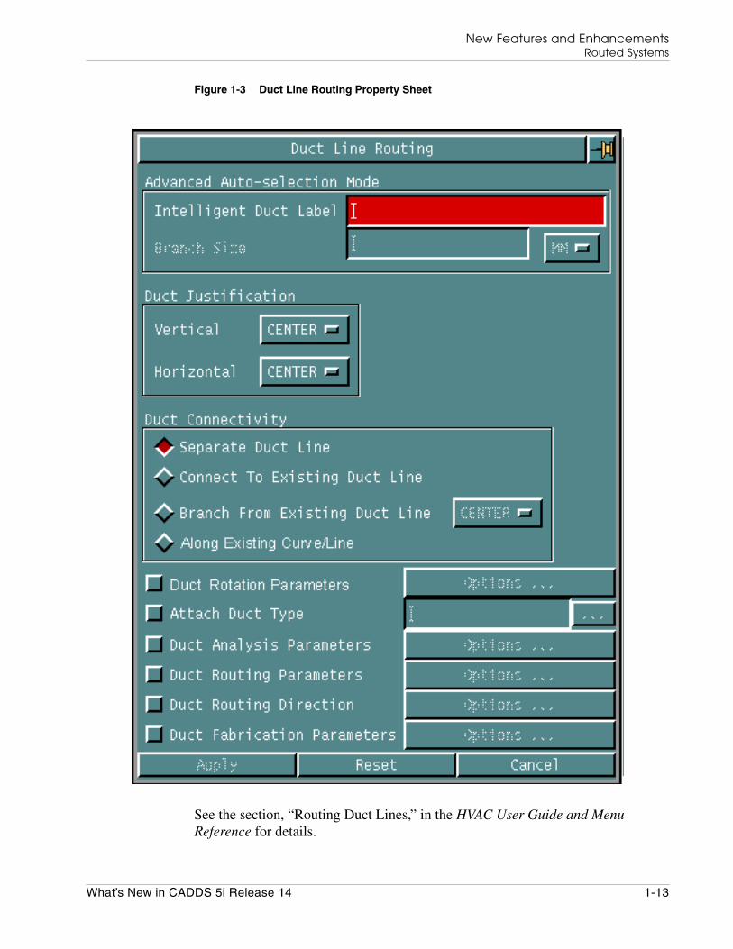
The Along Existing Curve/Line option on the Duct Line Routing property sheetallows you to route a duct line along an existing curve or line.
New Features and EnhancementsRouted Systems
What’s New in CADDS 5i Release 14 1-13
Figure 1-3 Duct Line Routing Property Sheet
See the section, “Routing Duct Lines,” in the HVAC User Guide and MenuReference for details.

New Features and EnhancementsRouted Systems
1-14 What’s New in CADDS 5i Release 14
Marking Penetration on Structural Objects
You can now use the INTERSECT COMMAND to mark the cross sections ofintersection of Nlines and Nfigures.
See the section, “Intersecting Entities,” in the Explicit Modeling User Guide andMenu Reference for details.
HVAC and Piping - Common Enhancements
Enhancements common to HVAC and Piping are described in the followingsections. Differences, if any, are also mentioned.
Reconstructing Selected Ductline or Pipeline Spools
You can now reconstruct a single selected spool or a few selected spools in aspooled duct line or pipeline using the Partial option in the Ductline SpoolGeneration/ Reconstruction property sheet or in the Pipeline Spool Generation/Reconstruction property sheet, respectively.

New Features and EnhancementsRouted Systems
What’s New in CADDS 5i Release 14 1-15
Figure 1-4 Duct Line Spool Generation / Reconstruction Property Sheet

New Features and EnhancementsRouted Systems
1-16 What’s New in CADDS 5i Release 14
Figure 1-5 Pipe Line Spool Generation / Reconstruction Property Sheet
You can use the Partial option to select the spool or spools to be reconstructed.You can either select the spools or specify a series of spools by typing the startingspool label and ending spool label in the From Spool and To Spool fields,respectively.

New Features and EnhancementsRouted Systems
What’s New in CADDS 5i Release 14 1-17
See the sections, “Generating or Reconstructing Ductline Spools,” in the HVACUser Guide and Menu Reference, or “Generating or Reconstructing PipelineSpools,” in the Piping User Guide and Menu Reference for details.
Unique Spool Name Across Ductlines or Pipelines
While generating a duct line or a pipeline database, you can now choose to preventduplication of spool names across parts in the selected project of the Oracledatabase.
See the sections, “Ductline External Database,” in the HVAC User Guide andMenu Reference, or “Pipeline External Database,” in the Piping User Guide andMenu Reference for details.
Manipulating and Copying Duct or Pipe Elements
You can now edit an existing duct or pipe element or create a copy of an existingduct or pipe element with the same or revised attribute values as the original ductor pipe element.
Figure 1-6 Manipulate Duct Element Property Sheet

New Features and EnhancementsRouted Systems
1-18 What’s New in CADDS 5i Release 14
Figure 1-7 Manipulate Piping Element Property Sheet
You can also modify the following attributes of a duct or a pipe element aftercreating the duct or pipe element.
• Layer on which the duct or pipe element lies
• Properties
• Name
• Angle of rotation
• End types of the inlet, outlet, and branch type Cnodes of the duct or pipeelement
• Branch orientation
See the sections, “Manipulating Duct Elements,” in the HVAC User Guide andMenu Reference, or “Manipulating Pipe Elements,” in the Piping User Guide andMenu Reference for details.
Additional Columns in the Duct or Piping Report
You can now choose to display the following new columns in the duct or pipingreport in addition to the existing columns:
• Layer
• MIPTR

New Features and EnhancementsRouted Systems
What’s New in CADDS 5i Release 14 1-19
• Properties of the duct or pipe elements
• UID
• X-, Y-, and Z-coordinates
See the sections, “Reporting Ductlines with Options,” in the HVAC User Guideand Menu Reference, or “Generating a Piping Report (with Options),” in thePiping User Guide and Menu Reference for details.
Cable Enhancements
Cable-related enhancements are described in the following sections. See the ShipElectrical Menu and Technical Reference for details.
Cableway Routing
You can now route cableways along existing curves or lines. These curves arecalled guiding curves. You can also set the cross-section orientation (rotation) andthe cross-section size along each segment of the guiding curves. You can use anyof the following entity types as guiding curves:
• Arc
• Bspline
• Conic
• Curve pole
• Draft curve
• Line
• Nodal line
• Nspline
• Spline
• String
You can route a cableway along existing curves or lines using the Along ExistingCurve/Line option on the Routing Options property sheet.

New Features and EnhancementsRouted Systems
1-20 What’s New in CADDS 5i Release 14
Figure 1-8 Routing Options Property Sheet
See the section, “Routing Cableways,” in the Ship Electrical Menu and TechnicalReference for details.
Piping Enhancements
Piping enhancements are described in the following sections. See the Piping UserGuide and Menu Reference and Piping Reference for details.
Interspool Entities in Piping Report
You can now choose to display interspool entities such as gaskets and fittings inthe Piping report, by using the Unspooled Format option in the Piping Reportproperty sheet.

New Features and EnhancementsRouted Systems
What’s New in CADDS 5i Release 14 1-21
Figure 1-9 Piping Report Property Sheet
See the section, “Generating a Piping Report (with Options),” in the Piping UserGuide and Menu Reference for details.
Multiple Pipe Bending Machines
While inserting a pipe bend, you can now choose to select the bend ratio from a listof predefined bend ratios.

New Features and EnhancementsRouted Systems
1-22 What’s New in CADDS 5i Release 14
Figure 1-10 Select Bend Ratio Property Sheet
The Select Bend Ratio property sheet displays a list of bend ratios specified in theBEND_MACHINE_LIST file. This file contains the bend ratio and the allowableclamp length, mapped against several combinations of size and specification of thebend for multiple bending machines.
See the section, “Inserting Pipe Bends (with Options),” in the Piping User Guideand Menu Reference for details.
Bend Insertion Failure Message
If the pipeline bend insertion process fails, a detailed error message is nowdisplayed listing the pipeline MIPTR, the coordinates of the vertex, and the reasonfor the failure.
Annotate Coordinates
In addition to the Northing/Southing, Easting/Westing, and Elevation datum types,you can now perform the annotate coordinates operation along the Longitudinal,Transverse, or Water Plane datum of the Ship Reference System.
The Annotate Coordinates property sheet has been enhanced to provide thisfunctionality.

New Features and EnhancementsRouted Systems
What’s New in CADDS 5i Release 14 1-23
Figure 1-11 Annotate Coordinates Property Sheet
See the section, “Annotating Coordinates (with Options),” in the Piping UserGuide and Menu Reference for details.
Inserting Fittings at Spool Points
You can now insert a fitting set at a spool point by using the Fitting at Spool Pointoption in the Pipe Line Spool Generation/ Reconstruction property sheet.
See the section, “Generating or Reconstructing Pipeline Spools,” in the PipingUser Guide and Menu Reference for details.

New Features and EnhancementsRouted Systems
1-24 What’s New in CADDS 5i Release 14
Clamp Length Check
While creating a pipe bend, a warning message is now displayed if the clamplength is less than the allowable clamp length. The inserted bend is highlighted inlight green. The list of allowable clamp lengths is stored in the pmaninfo file.
See the section, “Inserting Pipe Bends (with Options),” in the Piping User Guideand Menu Reference for details.
Multiple Clearances in Equipment
You can now add more than one clearance type to any equipment. You can create aclearance shape by using the Clearance Shape option in the ConstructEquipment property sheet.
Figure 1-12 Construct Equipment Property Sheet

New Features and EnhancementsRouted Systems
What’s New in CADDS 5i Release 14 1-25
The Clearance Shape option creates a new property named CLNAME to store theclearance section name.
See the section, “Constructing Equipment,” in the Piping User Guide and MenuReference for details.
Copying Nlines With Entire Nline Network
Using the new Revise Nline property sheet, you can now copy Nlines or selectedNline spools with their entire Nline network, that is, the Nlines and their fittings.

New Features and EnhancementsRouted Systems
1-26 What’s New in CADDS 5i Release 14
Figure 1-13 Revise Nline Property Sheet

New Features and EnhancementsRouted Systems
What’s New in CADDS 5i Release 14 1-27
See the section, “Copying Pipelines,” in the Piping User Guide and MenuReference for details.

New Features and EnhancementsShipbuilding Design
1-28 What’s New in CADDS 5i Release 14
Shipbuilding Design
Enhancements in CV Hull and Structural Modeling are described in the followingsections.
CV Hull
Enhancements in CV Hull are described in the following sections. For moreinformation, refer to CV Hull Manufacturing Commands.
Displaying Associated Plates in Stiffener Drawings
You can now choose to display all STplates related to the stiffener in the stiffenerdrawing. This new feature allows you to display the profile of the STplate if theSTplate is parallel to and lying on the flange or web surfaces of the stiffener. TheSTplates perpendicular to or inclined at an angle to the stiffener but touching thestiffener (web or flange), are represented as lines marked with appropriatethickness lines. For perpendicular or inclined plates, you can control the display ofthe STplate by using the following parameters in the nestparams file:
• STIFF-THICK-OFFSET-DIST
• STIFF-THICK-LINE-LENGTH
• STIFF-THICK-LINE-LOCATION
• STIFF-THICK-LINE-STYLE
Creating Cutouts in Not To Scale Mode
You can create cutouts in structural objects even while generating a drawing in theNot To Scale mode.
Related STobjects in the Shell Expansion Drawing
In a shell expansion drawing, you can now display trace lines of all STobjects, thatis, stiffeners and plates, that are related to each other or welded together. You canalso specify the marking fonts for the tracing lines against the following variablesin the nestparams file:
• SHEXP-SEAM-FONT for seam weld trace lines
• SHEXP-BUTT-FONT for butt weld trace lines
• SHEXP-STELEMENT-FONT for stiffener trace lines
• SHEXP-STPLATE-FONT for STplate trace lines

New Features and EnhancementsShipbuilding Design
What’s New in CADDS 5i Release 14 1-29
Display of Single Stiffener Across Plate Boundaries
By modifying the value of the PANEL-STIFFENER-LAYOUT parameter defined inthe nestparams file, you can now modify the display of a single stiffener thatcrosses multiple plates.
• If the value of the PANEL-STIFFENER-LAYOUT parameter is zero, then onestiffener line and one thickness line for each plate is displayed in the paneldrawing. If this parameter is not defined in the nestparams file, then its valueis considered to be zero.
• If the value of the PANEL-STIFFENER-LAYOUT parameter is one, then onlyone single stiffener line and one thickness line for the stiffener are displayed.
Stiffener Web Direction
In panel drawings, the direction of the stiffener web on adjacent plates near theplate edge is displayed whenever the stiffener length is more than half the platelength.
Fonts for Front and Back STObjects
In ship drawings, you can now represent stiffeners in the front and back of thepanel by using different fonts. The methods for specifying the fonts for the frontand back stiffeners are as follows in the order of precedence:
• The FRONT-STIFF-MARKING-FONT and BACK-STIFF-MARKING-FONTparameters in the nestparams file.
• The type of object defined using the STClass property in theclassifications file.
• The STIFF-MARKING-FONT parameter in the nestparams file. Use thisoption to display the same font for the front and back stiffeners.
• Default. If you do not specify any of the above options, then the front stiffenersare displayed in solid font, while the stiffeners are displayed in dashed font.
Better Layer Control for Flanged Plates
You can now differentiate between bending lines and stiffener lines by displayingthem in different fonts.
Bending lines are displayed in the font specified for the new parameter,IGES-ROLL-LINE-LAYER, in the nestparams file, while stiffener lines aredisplayed in the font specified for the IGES-GEOM-MARKING-LAYER parameter.

New Features and EnhancementsShipbuilding Design
1-30 What’s New in CADDS 5i Release 14
Plate Bevel Text
While creating structural welds, you can now specify the direction of the bevelopening of the weld, that is, if the bevel opening should be at the top or bottom ofthe plate.
You can insert bevel symbols in plate drawings, and bevel text in the nesting filefor butt and seam welds.
Structural Modeling Enhancements
Enhancements in Structural Modeling are described in the following sections. Seethe Advanced Structural Modeling User Guide and Menu Reference for details.
Additional Parameters for Ship Drawings
You can now generate ship drawings by specifying additional parameters such as:
• The section plane on which the drawing is to be generated
• The vertical and horizontal extents of the drawing
See the section, “Generating Ship Drawings,” in CV Hull ManufacturingCommands for details.
Line Fonts in Section Drawings
By modifying the value of the STIFF-REP parameter in the nestparams file, youcan now use either single or double lines in section drawings to represent thestiffener landings whose axes are parallel to the section plane.
The representation of stiffener landings based on each value of the STIFF-REPparameter is as follows:
• Zero, for a double line representation
• One, for a single line representation
• Two, for a single or double line representation, based on the followingconditions:
A double line representation is used when:
• The depth of the stiffener is parallel to the section plane. In this case, theoutline of the complete profile is displayed.
• The width of the stiffener is parallel to the section plane and the stiffenersection crosses the section plane, even though the stiffener axis is parallel to

New Features and EnhancementsShipbuilding Design
What’s New in CADDS 5i Release 14 1-31
the section plane. In this case, the complete profile of the stiffener is notdisplayed. Instead, only the web that crosses the section is displayed in adouble line font.
A single line representation is used when the width of the stiffener is parallel tothe section plane and the stiffener does not cross the section plane, that is, thestiffener just touches the section plane.
See the section, “Generating Ship Drawings,” in CV Hull ManufacturingCommands for details.
Stiffener Drawing for Bars in a Stiffener
You can now create a stiffener drawing only for the bars in a fabricated stiffener,while ignoring other components of the stiffener that are made of plates. You cangenerate a drawing for each bar of the fabricated section.
See the section, “Generating Stiffener Drawings,” in CV Hull ManufacturingCommands for details.
STCLASS Property on Structural Object Placement
You can now insert the STCLASS property while creating an STobject and assign aShip Classification Code to it.
You can either type the ship classification code manually or select from apredefined list of ship classification codes specified in a classdata file.
See the section, “Creating Structural Objects,” in the Advanced StructuralModeling User Guide and Menu Reference for details.
Twisted Stiffener on Multiple Surfaces
You can now insert a twisted stiffener over multiple surfaces using either a singleaxis curve running over multiple surfaces or joining multiple axis curves runningover multiple surfaces.
• If you select a twist curve as the twist entity, then the cross section of thestructural element is twisted toward the twist curve at each point on its axis.
• If you select a twist surface as the twist entity, then the element cross sectionfollows the normal direction of the twist surface at each point on the axis.
See the section, “Creating Structural Element,” in the Advanced StructuralModeling User Guide for details.

New Features and EnhancementsShipbuilding Design
1-32 What’s New in CADDS 5i Release 14
Copying Structural Objects With Their Attributes
You can now choose to copy STobjects with their attributes while transformingthem, that is, while moving, rotating, or mirroring them. All attributes of theSTobject except the name of the original STobject are copied to the targetSTobject.

New Features and EnhancementsDesign and User Support
What’s New in CADDS 5i Release 14 1-33
Design and User Support
Enhancements in Design and User Support are described in the following sections.See the Concurrent Assembly Mock-up User Guide and the Parametric ModelingUser Guide and Menu Reference for details.
Assembly Tree Window
The assembly tree window now has the following features:
• The assembly tree window is now split into two parts, that is, the assembly treeand the status window. The status window displays the properties of the nodethat is currently selected in the assembly tree.

New Features and EnhancementsDesign and User Support
1-34 What’s New in CADDS 5i Release 14
Figure 1-14 Assembly Tree
• You can switch the states of the component nodes by double-clicking thecorresponding icon in the assembly tree.
• The assembly tree now contains a toolbar that provides you with options toperform some important operations through a single mouse click.
• You can now control the default size and location of the assembly tree by usingthe new environmental variable, CV_ASSEMBLY_GEOM.
• You can choose to display either the model names or component names of thenodes in the assembly tree.

New Features and EnhancementsDesign and User Support
What’s New in CADDS 5i Release 14 1-35
See the section, “Assembly Tree,” in the Concurrent Assembly Mock-up UserGuide and Menu Reference for details.
Saving and Restoring Viewstates
You can now save the viewstates of an assembly to a file and restore themwhenever required by clicking the Save/Restore Viewstates option on theAdrawing menu on the top bar.
You can also choose restore the viewstates of one adrawing to another adrawing ofthe same assembly using the same option.
See the section, “Basic Steps to Create an Alternate View,” in the ConcurrentAssembly Mock-up User Guide and Menu Reference for details.
Parametric History Validation Tool
The Parametric History Validation Tool is a new utility that reruns all thecommands in a parametric part and reports the success or failure of the operation.You can run this utility using one of the following methods:
• Run the REGENERATE HISTORY GO command
• Select the Regen History option on the Parameter menu on the top bar.
• Middle-click the model node, that is, the root node in the history tree and selectthe Regen History option on the menu that appears.
If any command fails while the Parametric History Validation tool reruns all thecommands, then the reexecution process is aborted and the reasons for the failureand the possible fixes are listed in the report window. You can also choose to writethis information to a text file.
See the section, “Parametric History Validation Tool,” in the Parametric ModelingUser Guide and Menu Reference for details.

New Features and EnhancementsDesign and User Support
1-36 What’s New in CADDS 5i Release 14
Copying Constraints and Equations While Reusing PartHistory
While performing a Reuse History operation, you can now choose to copy thevariables, constraints, and equations related to a part, in addition to the geometryof the part.
The new Copy History / Constraint Selection property sheet contains the optionsto select the constraints and equations to be copied from the source part to thedestination part.
Figure 1-15 Copy History / Constraint Selection Property Sheet
You can select the option for each variable or equation, or both, to copy it to thedestination part.
When you click any of the nodes in the history tree, the constraints section of thehistory tree displays all the constraints related to the selected node, while theequations section displays all the equations related to the selected node.
Click the root model node to display all the constraints and equations in the part.

New Features and EnhancementsDesign and User Support
What’s New in CADDS 5i Release 14 1-37
See the section, “Copying the Part History,” in the Parametric Modeling UserGuide and Menu Reference for details.

New Features and EnhancementsDatabase Enhancements
1-38 What’s New in CADDS 5i Release 14
Database Enhancements
Database-related enhancements are described in the following sections. SeeManaging CADDS 5i for details.
The validate_db Utility
The validate_db utility and the CHECK DBASE command now detect andreport the following corruptions in AEC entities:
• Invalid STobjects
• Zero-length stiffeners
• Zero-material plates
• Self-referencing STobjects
See the section, “Validating a Part,” in Managing CADDS 5i for details.
The COMPARE PART Command
The COMPARE PART command has been extensively enhanced with this releaseof CADDS 5. An alternative method of comparison has been introduced using thepart UID and sequence numbers where parent child relationships exist betweenthe parts. The command now includes AEC entities in the types that may becompared. As a standalone utility, the command can also be invoked byEPD.Connect and the results reviewed in Visualizer or the 3D viewer. Thecommand now provides the following functionalities.
• You can now compare two parts that share a parent-child relationship.
• Using the new IDENT modifier, you can now write identical entities in theparts compared, to the output part.
• The entities in the output part are now displayed in different colors as follows:
• This command now identifies and compares the differences in the followingtypes of entities:
• Bsurface
Color Description
Green Entities unique to the first part
Red Entities unique to the second part
Orange Entities in the first part that are modified in the second part
Blue Identical entities in both the parts
New Features and EnhancementsDatabase Enhancements
What’s New in CADDS 5i Release 14 1-39
• Cnode
• Cpoint
• Cpole
• Cylinder
• Nodal line
• Nspline
• Nsurface
• Ruled surface
• Solid
• Spline
• Spoint
• Surface of revolution
• Tnode
See the section, “Managing Parts,” in the Explicit Modeling User Guide and MenuReference for details.

New Features and EnhancementsGeneral Enhancements
1-40 What’s New in CADDS 5i Release 14
General Enhancements
The following sections describe general enhancements.
COPY ENTITY Command
The COPY ENTITY command has a new modifier, SAMLAY, that enables you tocopy the selected entity or entities to the same layer from which each entity iscopied.
See the online help file for the COPY ENTITY command for details.
Checking Concurrency of Nfigures in Parts
You can now use the new REPORT NFIG command to generate a report thatdisplays the status of the instances of an Nfigure in a part. This report displays thefollowing information about instances of Nfigures:
• Type (local, external or nested)
• MIPTR (Master Index Pointer)
• Status (OUT-OF-DATE or UP-TO-DATE)
See the online help files for the REPORT NFIG command for details.
Optimum Zoom
You can now set the zoom status to ensure that all visible entities fit in the view.Using this functionality, you can frame all visible model entities in one or manyviews.
You can set the zoom status by selecting the Optimum Zoom option on the Zoommenu, or by using the ZOOM VOPT command.
The Show Optimum View property sheet contains various options required forperforming an optimum zoom operation.

New Features and EnhancementsGeneral Enhancements
What’s New in CADDS 5i Release 14 1-41
Figure 1-16 Show Optimum View Property Sheet
See the section, “Manipulating View Displays,” in the Explicit Modeling UserGuide and Menu Reference for details.
Reverse Blanking
You can now convert all blanked entities in a model to unblanked entities and viceversa, using reverse blanking. You can do this by selecting the Blank/Unblankoption on the Entity menu or by using the BLANK ENTITY command along withits REVERSE modifier.
See the section, “Controlling Visibility of CPL Symbols, View Frames, and OtherFeatures,” in the Explicit Modeling User Guide and Menu Reference for details.
Discriminate Active Layer
You can now display all the entities on all layers except the active layer, in a colorthat you select. This distinguishes the entities on the active layer from the otherentities.
You can perform this action by selecting the Set Layer Color option on the Setupmenu or by using the DISCRIMINATE LAYER command along with its ACTIVEmodifier.

New Features and EnhancementsGeneral Enhancements
1-42 What’s New in CADDS 5i Release 14
See the section, “Managing Layers from the Layer Bar,” in the Explicit ModelingUser Guide and Menu Reference for details.
Enhancements in Layer Selection
You now have the option to select the first free layer in a part by clicking thefollowing option on the layer bar.
You can also select the active layer at the time that the part was last filed, byclicking the following option on the layer bar.
See the section, “Managing Layers from the Layer Bar,” in the Explicit ModelingUser Guide and Menu Reference for details.
Creating Cplanes
You can now create Cplanes along any plane on an entity using the CREATECPLANE command.
See the online help for the CREATE CPLANE command for details.
Count of Model Entities
You can now count the number of model entities in a part by using the CountModel Entities option on the Query menu or by using the COUNT ENTITIEScommand along with its MODEL modifier.
See the section, “Counting Entities,” in the Explicit Modeling User Guide andMenu Reference for details.
Defining Auxiliary Views
You can now create a new view for the active model by recopying a portion of theexisting view and reusing the available layers.

New Features and EnhancementsGeneral Enhancements
What’s New in CADDS 5i Release 14 1-43
You can perform this action by using the Define option on the View menu. TheDefine View property sheet contains the options required to create an auxiliaryview.
Figure 1-17 The Define View Property Sheet
Alternatively, you can define an auxiliary view by using the DEFINE AUXVIEWcommand.
See the section, “Creating Views into Model Space,” in the Explicit Modeling UserGuide and Menu Reference for details.