Weld-end solidification cracking in pulsed-tandem gas...
28
ABSTRACT Pulsed tandem gas metal arc welding (PT-GMAW) has the potential to increase productivity and minimize distortion in the fabrication of naval surface ship panels. In this study, the PT-GMAW process was used in pulse-pulse mode to butt-weld 5 mm DH36, 8 mm HSLA65, 9.5 mm 350WT and 11 mm HSLA65 steel plate with ER70S-6 wire in order to assess its suitability as a replacement for submerged arc welding (SAW) and gas metal arc welding (GMAW) in panel lines of Australian naval shipyards. In the pulse-pulse mode, the wire feed rates for the leading and trailing welding wires are set independently and they alternately transfer metal into a single molten weld pool at deposition rates almost comparable with single-wire SAW. Radiographic inspection and subsequent analyses of the 8 mm, 9.5 mm and 11 mm single-bead butt-welds unexpectedly showed varying degrees of weld-end solidification cracking, which occurred within ~30 mm from the run-off tab and was different to weld-crater cracking. The percentage of plates with solidification cracking was greater at larger plate thicknesses due mainly to increases in both the weld bead depth:width ratio and joint restraint as plate thickness is increased. Also, relatively low levels of nickel in the weld metal resulted in less severe solidification cracks compared with weld metal with higher levels of nickel. There was no evidence of solidification cracks in the 5 mm welded plates. Potential strategies to overcome weld metal solidification cracking near the run-off tab in the PT-GMAW of steel are presented. Keywords Pulsed tandem gas metal arc welding Solidification cracking Naval hull steels HSLA65 steel DH36 steel Single-bead welds 1 Weld-end solidification cracking in pulsed-tandem gas-metal-arc welding of naval steels Zoran Sterjovski a,* , Christopher Bayley b , Joe Donato a , Nathan Lane c, d and Darren Lang e a Maritime Division, DSTO, Department of Defence, 506 Lorimer Street, Fishermans Bend, Victoria, 3207 Australia b DRDC ±Atlantic, Dockyard Laboratory Pacific, PO Box 17000 Stn Forces, Victoria, BC, Canada V9A 7N2 c Facullty of Engineering, University of Wollongong, Northfields Avenue, NSW 2500 Australia d DMTC Ltd, Level 2, 24 Wakefield St, Hawthorn VIC 3122 Australia e Forgacs Engineering Pty Ltd, Old Punt Road, Tomago, NSW 2322 Australia * Corresponding author. Tel.: +61 3 9626 7502; fax: +61 3 96268341; E-mail: [email protected]
-
Upload
vuongtuyen -
Category
Documents
-
view
227 -
download
3
Transcript of Weld-end solidification cracking in pulsed-tandem gas...
ABSTRACT
Pulsed tandem gas metal arc welding (PT-GMAW) has the potential to increase productivity and
minimize distortion in the fabrication of naval surface ship panels. In this study, the PT-GMAW process
was used in pulse-pulse mode to butt-weld 5 mm DH36, 8 mm HSLA65, 9.5 mm 350WT and 11 mm
HSLA65 steel plate with ER70S-6 wire in order to assess its suitability as a replacement for submerged
arc welding (SAW) and gas metal arc welding (GMAW) in panel lines of Australian naval shipyards. In the
pulse-pulse mode, the wire feed rates for the leading and trailing welding wires are set independently and
they alternately transfer metal into a single molten weld pool at deposition rates almost comparable with
single-wire SAW. Radiographic inspection and subsequent analyses of the 8 mm, 9.5 mm and 11 mm
single-bead butt-welds unexpectedly showed varying degrees of weld-end solidification cracking, which
occurred within ~30 mm from the run-off tab and was different to weld-crater cracking. The percentage of
plates with solidification cracking was greater at larger plate thicknesses due mainly to increases in both
the weld bead depth:width ratio and joint restraint as plate thickness is increased. Also, relatively low
levels of nickel in the weld metal resulted in less severe solidification cracks compared with weld metal
with higher levels of nickel. There was no evidence of solidification cracks in the 5 mm welded plates.
Potential strategies to overcome weld metal solidification cracking near the run-off tab in the PT-GMAW
of steel are presented.
Keywords Pulsed tandem gas metal arc welding
Solidification cracking
Naval hull steels
HSLA65 steel
DH36 steel
Single-bead welds
1
Weld-end solidification cracking in pulsed-tandem gas-metal-arc welding of naval steels
Zoran Sterjovski a,*, Christopher Bayley b, Joe Donato a, Nathan Lane c, d and Darren Lang e
a Maritime Division, DSTO, Department of Defence, 506 Lorimer Street, Fishermans Bend, Victoria, 3207 Australia b DRDC Atlantic, Dockyard Laboratory Pacific, PO Box 17000 Stn Forces, Victoria, BC, Canada V9A 7N2c Facullty of Engineering, University of Wollongong, Northfields Avenue, NSW 2500 Australia d DMTC Ltd, Level 2, 24 Wakefield St, Hawthorn VIC 3122 Australia e Forgacs Engineering Pty Ltd, Old Punt Road, Tomago, NSW 2322 Australia
* Corresponding author. Tel.: +61 3 9626 7502; fax: +61 3 96268341; E-mail: [email protected]
Naval shipbuilders can benefit from the high deposition rates of the PT-GMAW process by producing
single-pass welds of low cross-section or by increasing welding travel speeds. The latter approach, which
would result in the deposition of multiple beads during the welding of plates 8 mm in thickness, is more
likely to ensure adequate impact toughness in the weld metals of conventional shipping steels (e.g. DH36
and CSA 350WT) [6]. However, single-bead PT-GMAW of higher-strength steels (e.g. HSLA65) should
result in weldments with adequate impact toughness since the composition of the ER70S-6 weld metal
(WM) is bolstered via mixing (i.e. increased dilution) with the more highly alloyed parent steel [7].
The pulsed tandem gas metal arc welding (PT-GMAW) process, which is commercially available but not
yet optimized for wide-spread implementation into naval surface ship construction, has the potential to
replace conventional arc welding processes such as submerged arc welding (SAW) and gas metal arc
welding (GMAW). The appeal of the PT-GMAW process stems from its affordability compared with other
high speed processes such as laser-hybrid GMAW, and an ability to (i) achieve lower levels of weldment
distortion, (ii) deliver high deposition rates (comparable to SAW), and (iii) perform out-of-position welding.
In the PT-GMAW process, the wires (electrodes) are fed from separate wire feed units through to two
contact tubes, which are electrically isolated inside a single torch head. The power sources for both wires
(electrodes) are synchronized, thus enabling the coordinated transfer of metal from each wire into a
single weld pool. The system is most stable when the metal transfer between the wires is completely out-
of-phase, although shielding gas type will also influence arc stability [1]. Previous studies by Sterjovski et
al. [2,3] have reported both relatively low levels of welding-related distortion (compared with multi-run
GMAW) and deposition rates of ~15 kg/hour with a 400 A PT-GMAW system.
2
1. Introduction
Lower levels of welding-related distortion should significantly reduce delays to schedule since the
dependence on line-heating/flame straightening to rectify distortion is alleviated. Moreover, it is reported
by Sampath [4] that line-heating can be detrimental to the structural integrity of the hull if incorrectly
applied. Less distortion in hull sections will improve the stealth characteristics of naval surface ships by
reducing their radar cross-section [5]. It is also envisaged that naval surface ships with significantly less
hull distortion will reduce hydrodynamic drag, and consequently improve speed and fuel efficiency than
ships with greater levels of hull distortion.
The aim of the current work is to assess the suitability of the PT-GMAW process in different areas of
naval surface ship construction, in particular the PT-GMAW of steel plate 8 11 mm in thickness. The
successful implementation of PT-GMAW in other areas of the naval shipyard is dependent on
weld overlap, and WM solidification cracking at
the weld-ends during the single-bead butt-welding of hull plate ( 8 mm thick). The sole focus of this
paper is to discuss the extent and nature of weld metal solidification cracking that occurred during the PT-
GMAW of naval hull steels. Weld metal solidification cracking can be defined as cracking that occurs
during the solidification of the molten weld bead. Solidification cracking is due to critical levels of strain
accumulation in the solidifying weld pool as a result of thermal contraction within the material as well as
externally applied loads [9]. Solidification cracks initiate above the solidus temperature of the WM or due
to the presence of low melting temperature intergranular eutectic films created by the segregation of
impurity (e.g. S and P) and alloying elements (C, Ni and Nb) [10]. Accordingly, WM solidification cracking
is considered a complex cracking phenomenon dependent on parent steel and WM composition,
solidification structures, segregation, dendrite size and orientation, joint restraint, weld travel speed, arc
energy heat input and weld thickness [11,12].
3
A preliminary study by Larkin et al. [8] which assessed the feasibility of the PT-GMAW process as a
replacement for SAW for single-bead butt-welding of 5 mm DH36 steel showed that high weld quality and
good mechanical properties can be achieved. This achievement, combined with a significant reduction in
weld-related distortion compared with corresponding SAW weldments, has resulted in the PT-GMAW
process replacing SAW on some panel lines in the fabrication of naval surface ships in Australia.
2. Experimental Methods
2.1. Materials and welding
The current investigation into the optimization of the PT-GMAW process for naval shipbuilding
encompasses both currently-used and future naval shipbuilding steels. The currently-used grades of
steels included in this study are DH36 steel [13] and CSA 350WT steel [14]. HSLA65 steel [15] is the
potential hull steel considered for this study. The reasons for the selection of HSLA65 as a potential steel
for naval surface ships in Australia have previously been published [7]. The plate thicknesses and
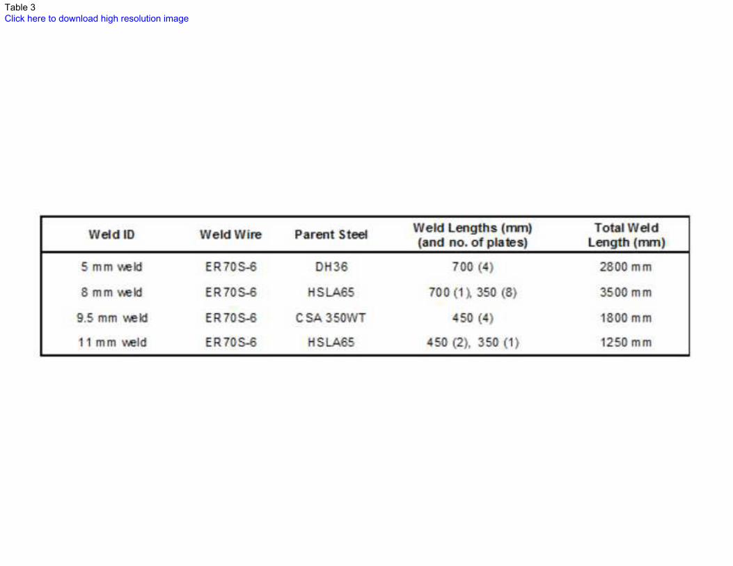
In total, 20 butt-welds at least 350 mm in length were evaluated for the current work (listed in Table 3). All
butt-welds were single-bead and full-penetration (square-butt preparation with a varying root gap
depending on plate thickness). The single-bead approach has been used in the current study as it will
lead to the biggest gains in productivity. It is also envisaged that this process will eventually compete with
other processes capable of low-distortion and high-productivity single-bead welding, such as laser hybrid
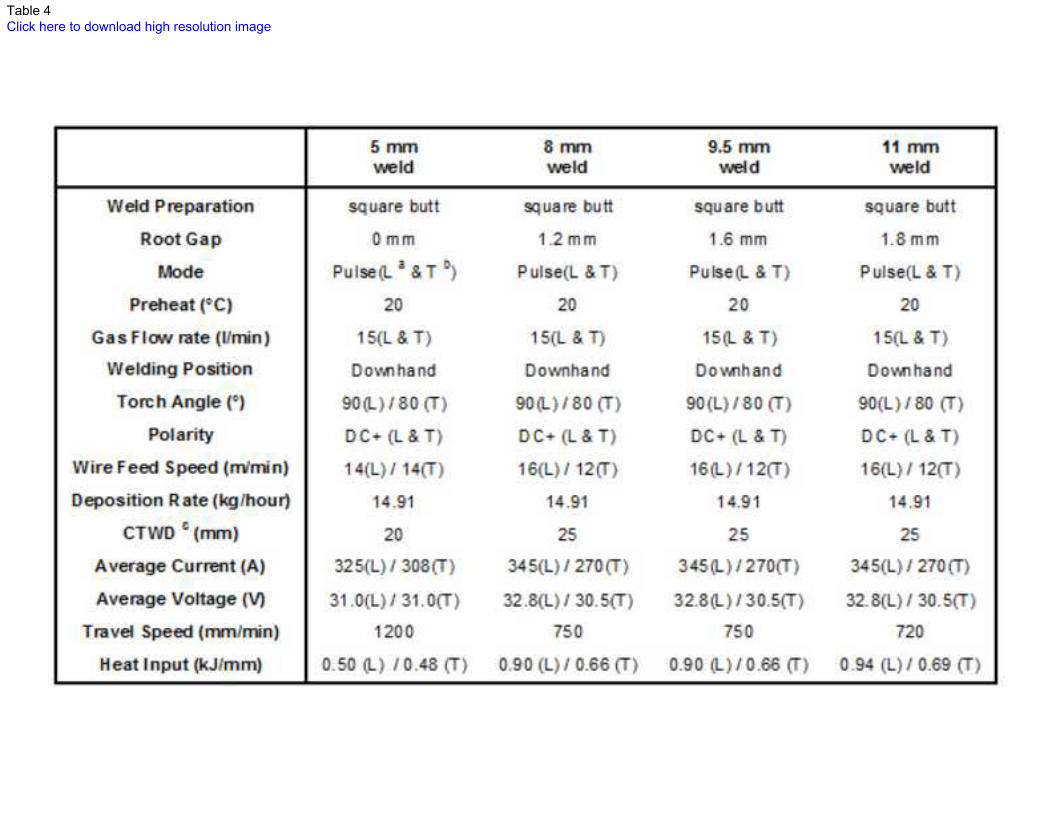
GMAW as its affordability improves. Table 4 lists all the critical weld process parameters for each of the
welds (5 mm DH36, 8 mm HSLA65, 9.5 mm CSA 350WT and 11 mm HSLA65). All plates were clamped
during welding, had tacked run-off and run-on tabs, and had machined weld preparations.
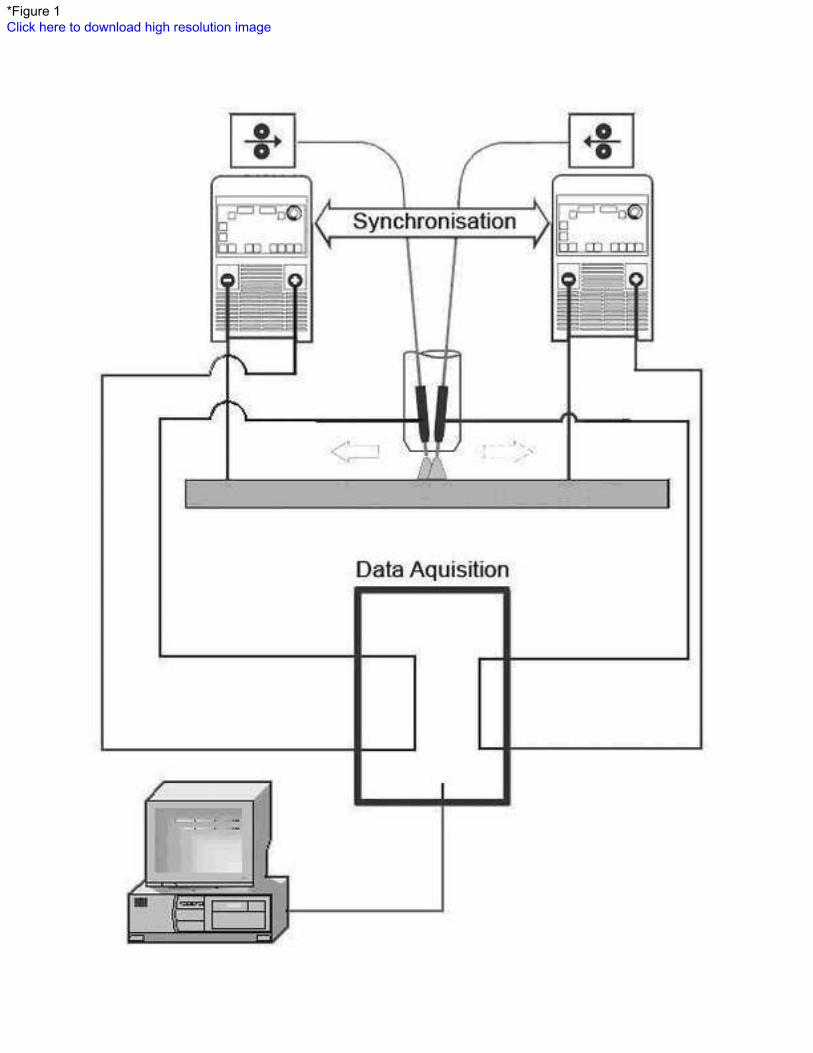
For all welding experiments, a single torch head attached to two Fronius Trans Synergic 4000 power
supply and wire feed systems was used. The two welders were synchronized to coordinate the metal
transfer from each electrode to the molten weld pool (Fig. 1). For synchronized metal transfer, a synergic
control system is implemented to ensure that a stable welding condition is maintained irrespective of the
wire feed rates or average current levels. Coordinated metal transfer is particularly important for arc
stability due to the proximity of the leading and trailing arcs (~5-6 mm). The welding parameters for each
unit can be individually adjusted because each wire has its own electrically insulated contact tip within the
single torch head. A high-speed-welding tractor was used to reach the required travel speeds.
4
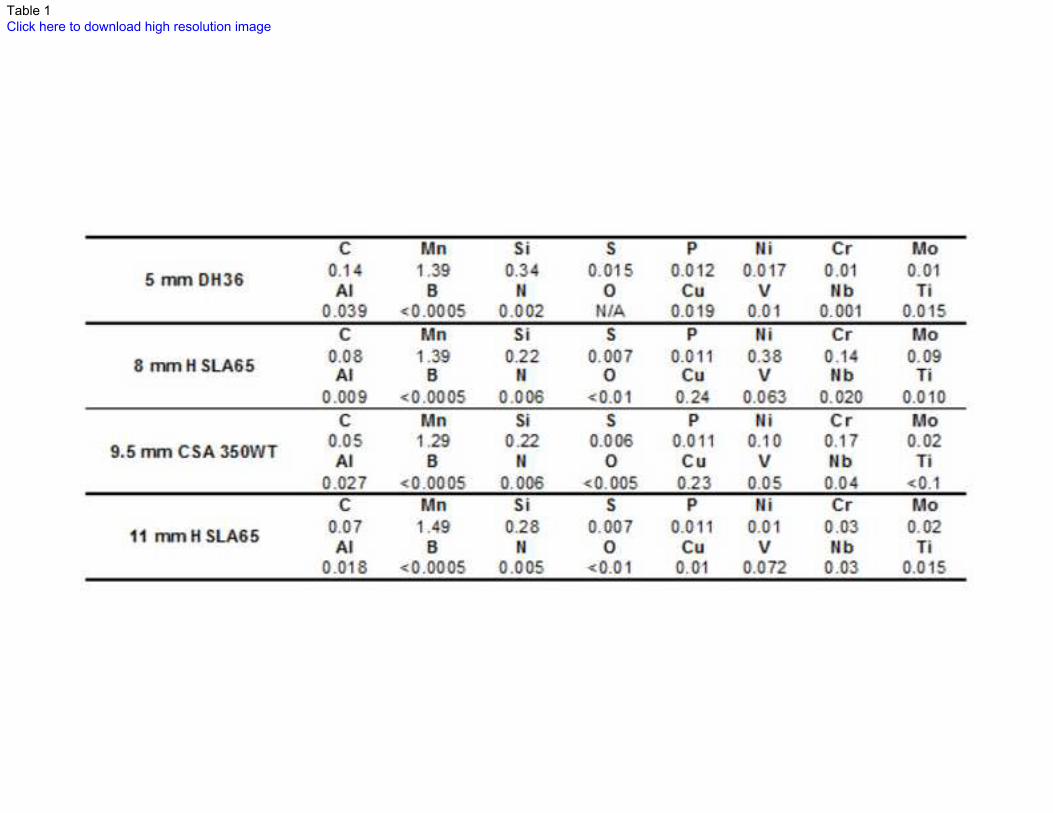
chemical compositions of the steels used for this study are listed in Table 1. Even though the chemical
composition of the two HSLA65 steels is different, they both comply with ASTM A945/A945M-06 [15].
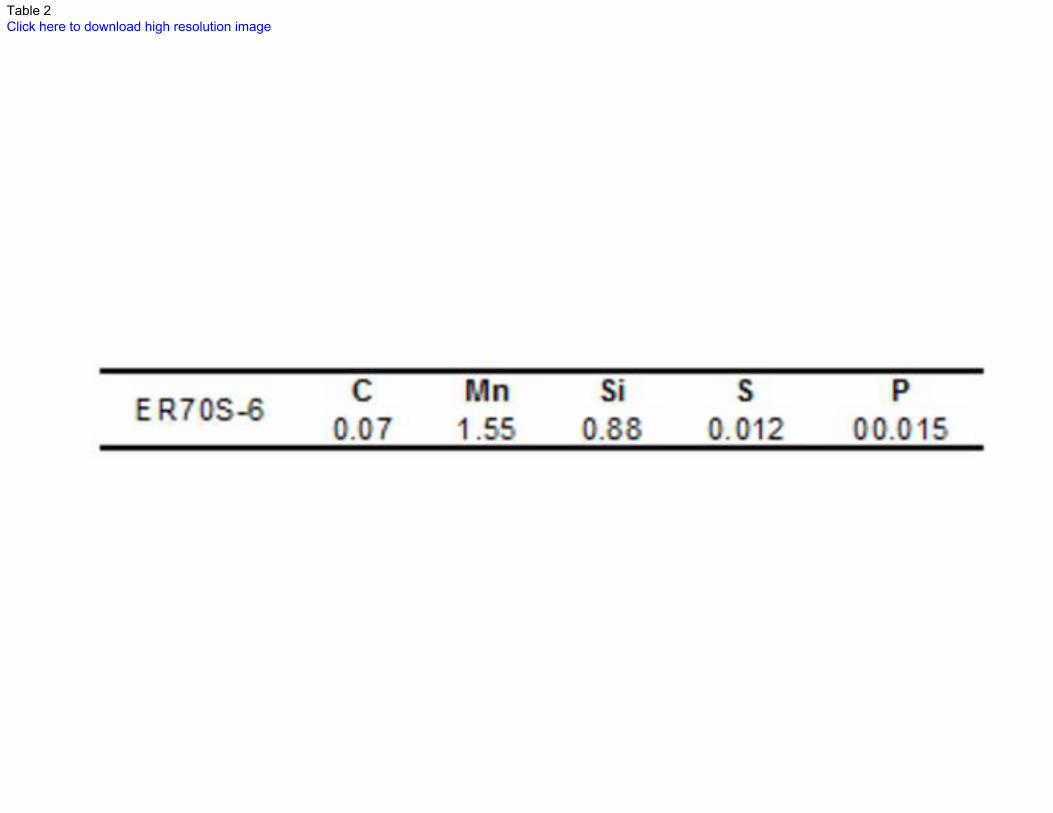
ER70S-6 wire (1.2 mm in diameter) and a shielding gas containing 16% CO2, 2.75% O2 and 81.25% Ar
were used for all single-bead full penetration butt-welds. The ER70S-6 wire was selected as it is currently
being used to weld fabricate DH36, and it also meets the strength and toughness requirements for
HSLA65 steel and CSA 350WT. The nominal chemical composition of the ER70S-6 wire is shown in
Table 2.
2.2. Radiography, optical emission spectroscopy, microscopy and fractography
All butt-welds were subjected to visual inspection and radiography in order to assess their quality. The
radiographic technique used was XR2/S (x-ray with Type 2 film/single wall) in accordance with
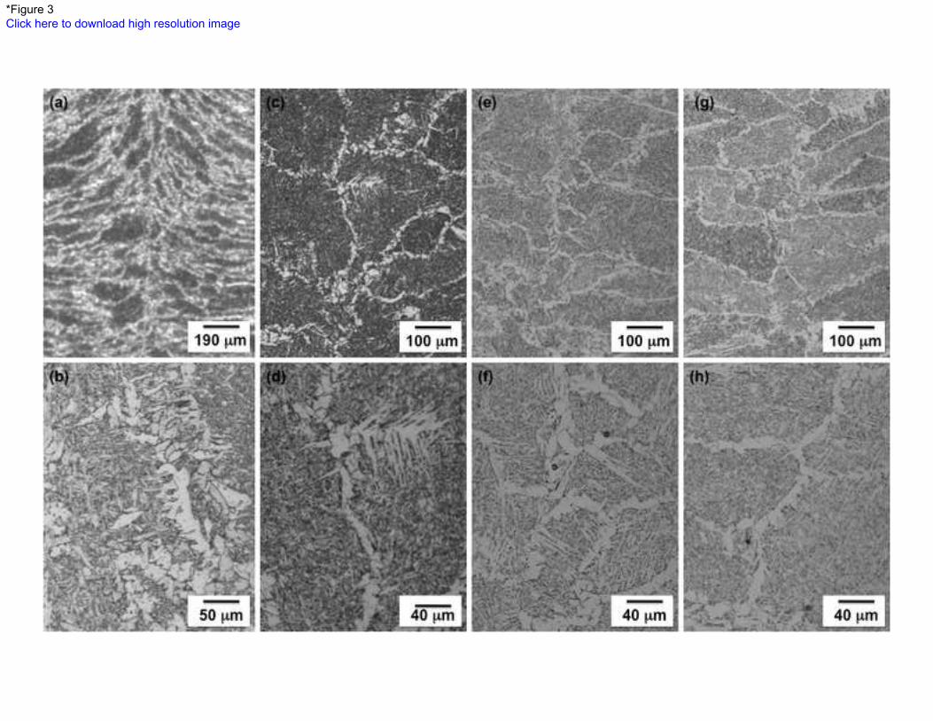
The WM microstructures of all the full-penetration butt-welds in the current work are shown in the
photomicrographs in Fig. 3. These photomicrographs are taken from the weld centerline and the center of
the weld with respect to weld length. From these photomicrographs it is evident that each of the weld
beads is comprised of combinations of acicular ferrite, grain boundary ferrite and Widmanstätten ferrite.
There was no WM solidification cracking evident in the center of the plate (i.e. at the center of the weld
length).
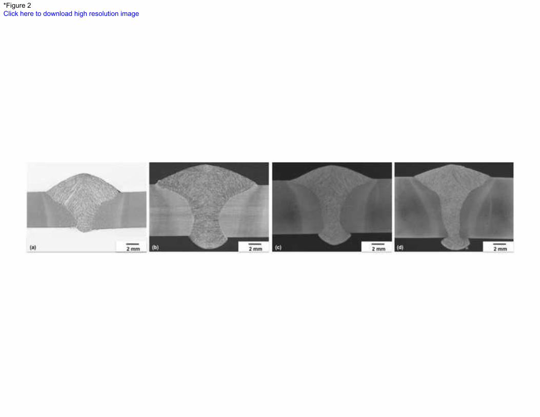
Macrographs of the 5, 8, 9.5 and 11 mm welds shown in Fig. 2(a-d) reveal that each of the welds are
single-bead full penetration butt-welds, and that they are free of any significant defects. In the
macrographs in Fig. 2 it is evident that weld bead depth-to-width ratio increases as plate thickness
increases. The weld bead depth:width ratio measured for the 5 mm, 8 mm, 9.5 mm, and 11 mm welds is
3.3, 3.3, 4.4 and 6.8, respectively.
5
AS2177-2006 [16]. All of the 9.5 mm welds and four of the 8 mm welds were tested in Canada, but met
the requirements of AS2177-2006 [16].
The majority of the welds were then sectioned, metallographically prepared, etched in 2% Nital and
evaluated by optical microscopy. Scanning electron microscopy (SEM) was also used to study the
fracture surfaces in each of the cracked welds. Chemical compositions of each of the weld metals were
determined by optical emission spectroscopy. Energy dispersive spectroscopy (EDS) was carried out on
the fracture surfaces of the solidification cracks.
3. Experimental Results
3.1. Weld macrographs
3.2. Weld metal compositions
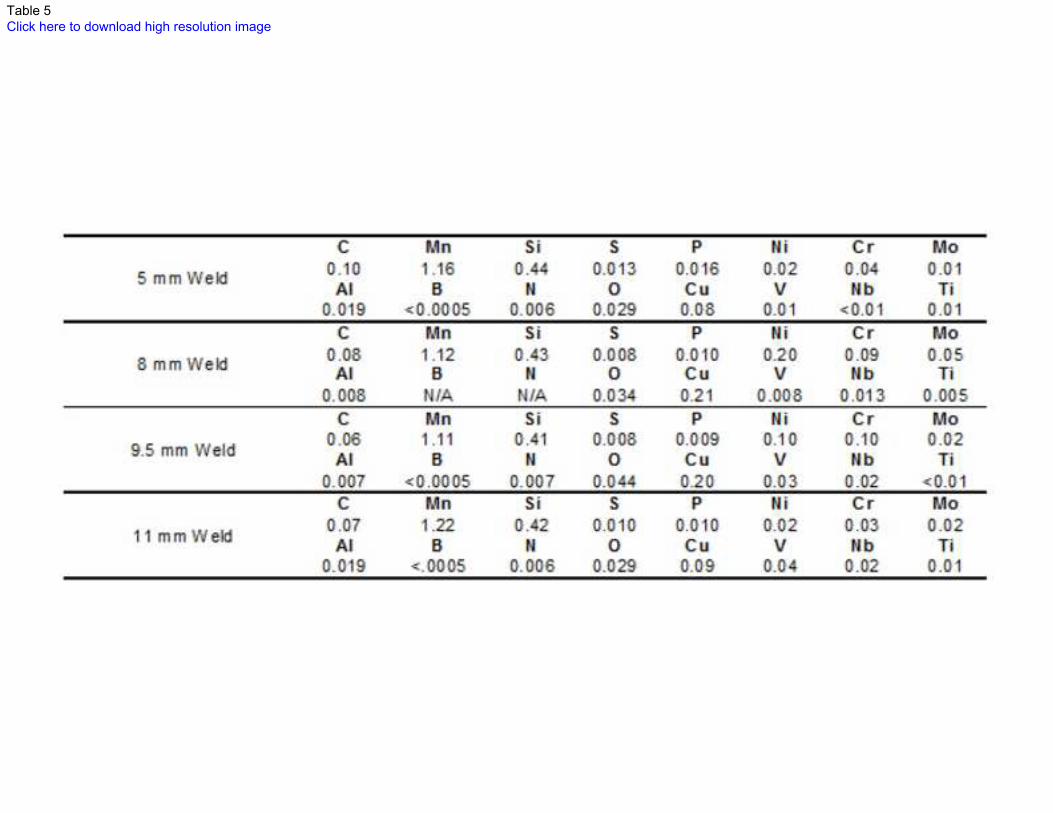
The chemical composition analysis of the WM region in the 5 mm, 8 mm, 9.5 mm and 11 mm welds is
shown in Table 5.
3.3. Weld metal microstructure

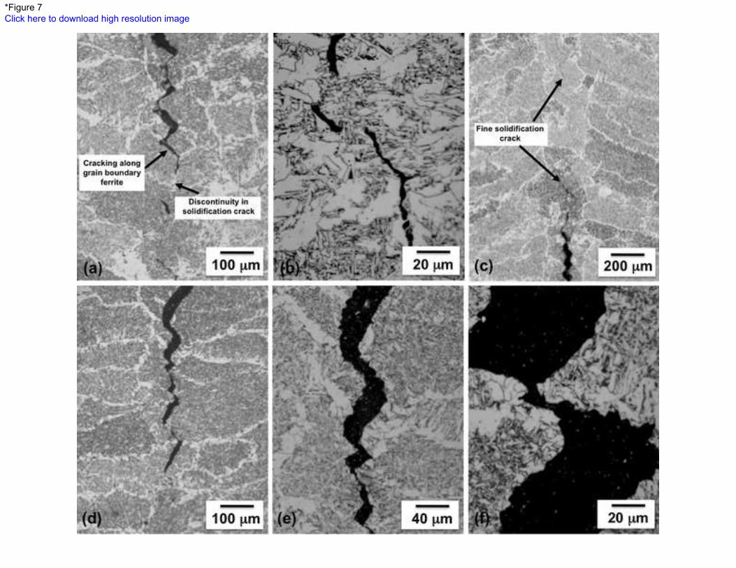
The location of the solidification cracking with respect to the weld microstructure in the 8, 9.5 and 11 mm
welds is shown in Fig. 7. The solidification cracking in the 8 mm weld appears to have propagated
predominantly along the grain boundary ferrite (Fig. 7 (a-b)). Similarly, the propagation of solidification
cracks along grain boundary ferrite is also evident in the 9.5 and 11 mm welds (Figure 7(c-f)).
Additionally, there is evidence of fine-scale solidification cracks and some discontinuity in the cracking
(Fig. 7 (a-c)).
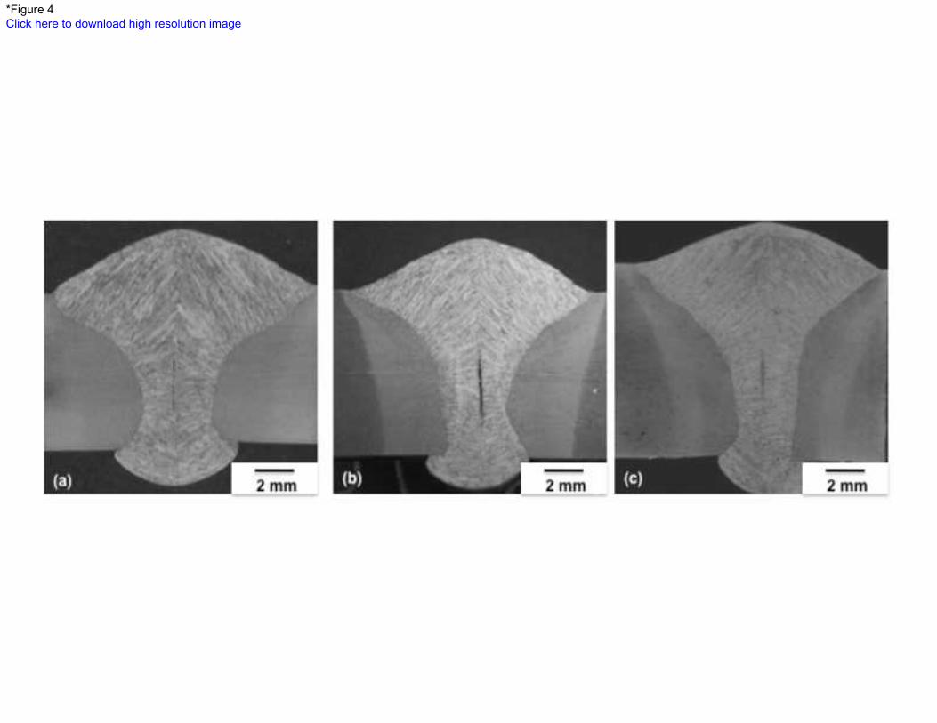
Fig. 4(a-c) shows macrographs of the cross-section (taken within 30 mm from the weld-end) of the 8 , 9.5
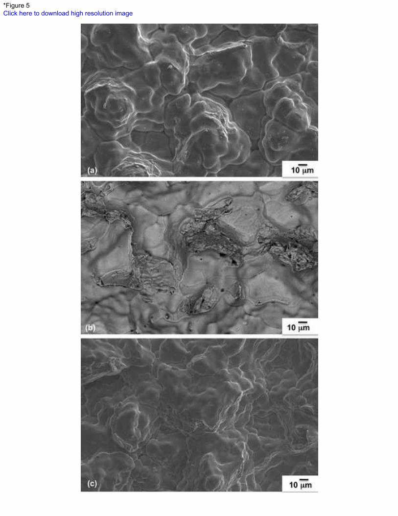
and 11 mm welds. Weld centerline cracking is evident in each of these welds. SEM fractography (Fig.
5(a-c)) confirmed that these crack defects are solidification cracks due to the smooth dendritic
appearance of the fracture surface. There were no cases of solidification cracking evident in the 5 mm
welds.
6
3.4. Weld metal solidification cracking
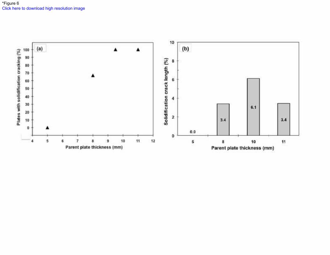
Plots of the number of welds with solidification cracking (% of total plates welded) and solidification
cracking length (% of total weld length) versus parent plate thickness are shown in Fig. 6. Based on the
available data, Fig. 6(a) shows that as plate thickness increases, then the likelihood of solidification
cracking increases. Fig. 6(b) shows that there is no direct linear relationship between plate thickness and
the extent of solidification cracking. The crack lengths were measured from x-ray radiographs, which was
also the method used to detect the plates with solidification cracks.
4. Discussion
Weld metal solidification cracking in the current study was unexpected. Firstly, there are no reported
cases in the literature of solidification cracking in PT-GMAW welds. Also, solidification cracking in
conventional single-wire GMAW of low alloyed steels is not widely reported. However, Shankar and
Devletian [17] do state that the role of C, Ni, S and P is more significant in conventional GMAW than for
SAW. Secondly, the outcome of a preliminary analysis on the chemical compositions of the parent steels
(Table 1) and the corresponding WM compositions (Table 5) indicated a very low susceptibility to the
onset of solidification cracking.
7
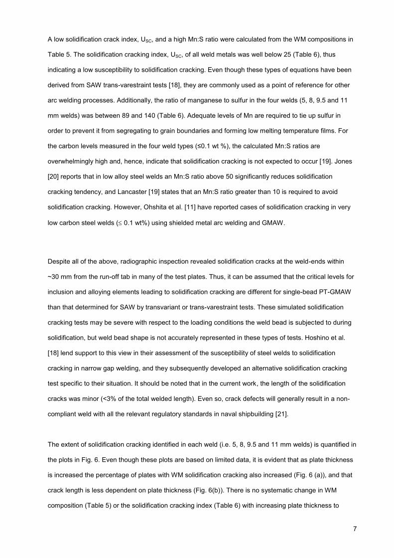
A low solidification crack index, USC, and a high Mn:S ratio were calculated from the WM compositions in
Table 5. The solidification cracking index, USC, of all weld metals was well below 25 (Table 6), thus
indicating a low susceptibility to solidification cracking. Even though these types of equations have been
derived from SAW trans-varestraint tests [18], they are commonly used as a point of reference for other
arc welding processes. Additionally, the ratio of manganese to sulfur in the four welds (5, 8, 9.5 and 11
mm welds) was between 89 and 140 (Table 6). Adequate levels of Mn are required to tie up sulfur in
order to prevent it from segregating to grain boundaries and forming low melting temperature films. For
:S ratios are
overwhelmingly high and, hence, indicate that solidification cracking is not expected to occur [19]. Jones
[20] reports that in low alloy steel welds an Mn:S ratio above 50 significantly reduces solidification
cracking tendency, and Lancaster [19] states that an Mn:S ratio greater than 10 is required to avoid
solidification cracking. However, Ohshita et al. [11] have reported cases of solidification cracking in very
low carbon steel welds ( 0.1 wt%) using shielded metal arc welding and GMAW.
Despite all of the above, radiographic inspection revealed solidification cracks at the weld-ends within
~30 mm from the run-off tab in many of the test plates. Thus, it can be assumed that the critical levels for
inclusion and alloying elements leading to solidification cracking are different for single-bead PT-GMAW
than that determined for SAW by transvariant or trans-varestraint tests. These simulated solidification
cracking tests may be severe with respect to the loading conditions the weld bead is subjected to during
solidification, but weld bead shape is not accurately represented in these types of tests. Hoshino et al.
[18] lend support to this view in their assessment of the susceptibility of steel welds to solidification
cracking in narrow gap welding, and they subsequently developed an alternative solidification cracking
test specific to their situation. It should be noted that in the current work, the length of the solidification
cracks was minor (<3% of the total welded length). Even so, crack defects will generally result in a non-
compliant weld with all the relevant regulatory standards in naval shipbuilding [21].
The extent of solidification cracking identified in each weld (i.e. 5, 8, 9.5 and 11 mm welds) is quantified in
the plots in Fig. 6. Even though these plots are based on limited data, it is evident that as plate thickness
is increased the percentage of plates with WM solidification cracking also increased (Fig. 6 (a)), and that
crack length is less dependent on plate thickness (Fig. 6(b)). There is no systematic change in WM
composition (Table 5) or the solidification cracking index (Table 6) with increasing plate thickness to
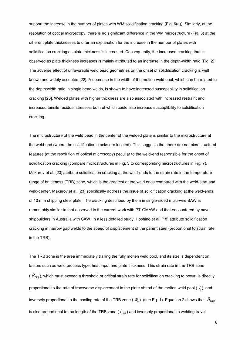
The TRB zone is the area immediately trailing the fully molten weld pool, and its size is dependent on
factors such as weld process type, heat input and plate thickness. This strain rate in the TRB zone
The microstructure of the weld bead in the center of the welded plate is similar to the microstructure at
the weld-end (where the solidification cracks are located). This suggests that there are no microstructural
features (at the resolution of optical microscopy) peculiar to the weld-end responsible for the onset of
solidification cracking (compare microstructures in Fig. 3 to corresponding microstructures in Fig. 7).
Makarov et al. [23] attribute solidification cracking at the weld-ends to the strain rate in the temperature
range of brittleness (TRB) zone, which is the greatest at the weld ends compared with the weld-start and
weld-center. Makarov et al. [23] specifically address the issue of solidification cracking at the weld-ends
of 10 mm shipping steel plate. The cracking described by them in single-sided multi-wire SAW is
remarkably similar to that observed in the current work with PT-GMAW and that encountered by naval
shipbuilders in Australia with SAW. In a less detailed study, Hoshino et al. [18] attribute solidification
cracking in narrow gap welds to the speed of displacement of the parent steel (proportional to strain rate
in the TRB).
support the increase in the number of plates with WM solidification cracking (Fig. 6(a)). Similarly, at the
resolution of optical microscopy, there is no significant difference in the WM microstructure (Fig. 3) at the
different plate thicknesses to offer an explanation for the increase in the number of plates with
solidification cracking as plate thickness is increased. Consequently, the increased cracking that is
observed as plate thickness increases is mainly attributed to an increase in the depth-width ratio (Fig. 2).
The adverse effect of unfavorable weld bead geometries on the onset of solidification cracking is well
known and widely accepted [22]. A decrease in the width of the molten weld pool, which can be related to
the depth:width ratio in single bead welds, is shown to have increased susceptibility in solidification
cracking [23]. Welded plates with higher thickness are also associated with increased restraint and
increased tensile residual stresses, both of which could also increase susceptibility to solidification
cracking.
8
( TRBB ), which must exceed a threshold or critical strain rate for solidification cracking to occur, is directly
proportional to the rate of transverse displacement in the plate ahead of the molten weld pool ( tv ), and
inversely proportional to the cooling rate of the TRB zone ( 0w ) (see Eq. 1). Equation 2 shows that TRBB
is also proportional to the length of the TRB zone ( TRBl ) and inversely proportional to welding travel
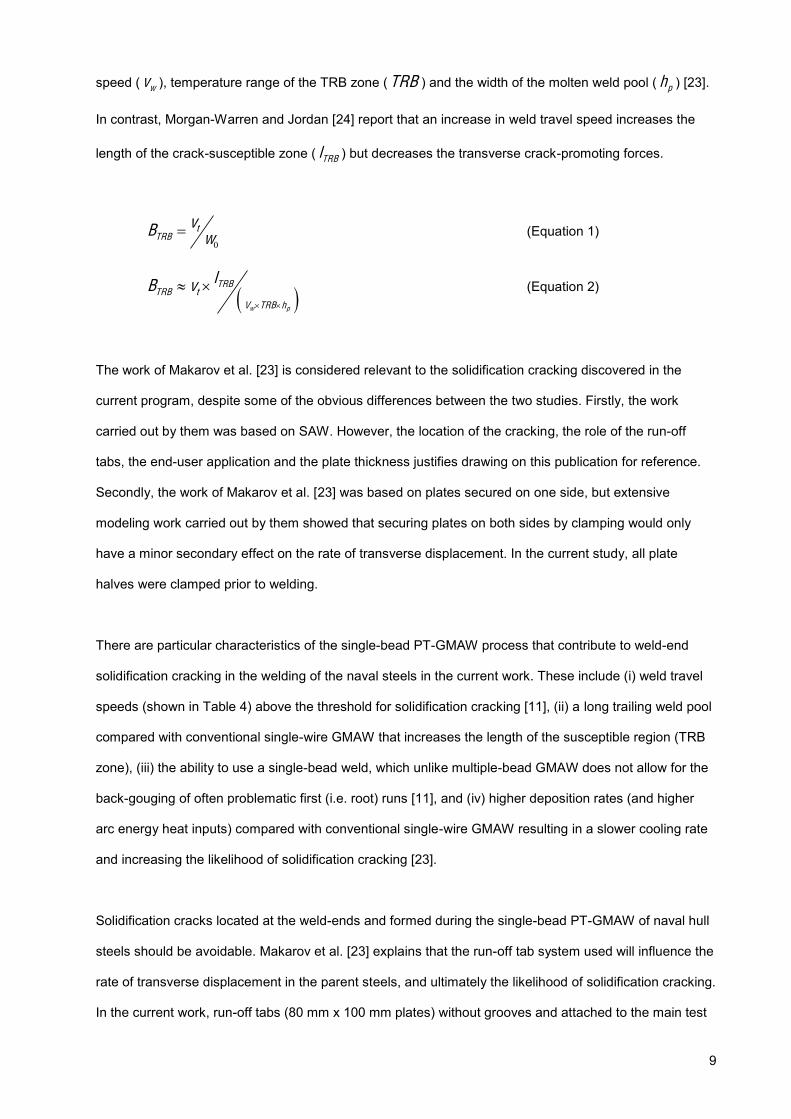
There are particular characteristics of the single-bead PT-GMAW process that contribute to weld-end
solidification cracking in the welding of the naval steels in the current work. These include (i) weld travel
speeds (shown in Table 4) above the threshold for solidification cracking [11], (ii) a long trailing weld pool
compared with conventional single-wire GMAW that increases the length of the susceptible region (TRB
zone), (iii) the ability to use a single-bead weld, which unlike multiple-bead GMAW does not allow for the
back-gouging of often problematic first (i.e. root) runs [11], and (iv) higher deposition rates (and higher
arc energy heat inputs) compared with conventional single-wire GMAW resulting in a slower cooling rate
and increasing the likelihood of solidification cracking [23].
9
speed ( wv ), temperature range of the TRB zone ( TRB ) and the width of the molten weld pool ( ph ) [23].
In contrast, Morgan-Warren and Jordan [24] report that an increase in weld travel speed increases the
length of the crack-susceptible zone ( TRBl ) but decreases the transverse crack-promoting forces.
0
tTRB
vB w (Equation 1)
w p
TRBTRB t
V TRB h
lB v (Equation 2)
The work of Makarov et al. [23] is considered relevant to the solidification cracking discovered in the
current program, despite some of the obvious differences between the two studies. Firstly, the work
carried out by them was based on SAW. However, the location of the cracking, the role of the run-off
tabs, the end-user application and the plate thickness justifies drawing on this publication for reference.
Secondly, the work of Makarov et al. [23] was based on plates secured on one side, but extensive
modeling work carried out by them showed that securing plates on both sides by clamping would only
have a minor secondary effect on the rate of transverse displacement. In the current study, all plate
halves were clamped prior to welding.
Solidification cracks located at the weld-ends and formed during the single-bead PT-GMAW of naval hull
steels should be avoidable. Makarov et al. [23] explains that the run-off tab system used will influence the
rate of transverse displacement in the parent steels, and ultimately the likelihood of solidification cracking.
In the current work, run-off tabs (80 mm x 100 mm plates) without grooves and attached to the main test

The solidification cracks found in the 11 mm weld were less severe than those found in the other welds.
Cracks in the 11 mm welds were not as long and deep compared with those in the 8 mm and 9.5 mm
welds (compare Fig. 4(c) with Fig. 4(a-b)). This was also confirmed in the radiographs of the 11 mm weld
by their relatively short lengths and lighter appearance. The small size of the solidification cracks in the
11 mm weld, despite it having the greatest weld bead depth-width ratio, is attributed to a significantly
lower level of Ni in the WM. The 11 mm weld measured at least 5 times less Ni than 8 mm weld and 10
times less Ni than 9.5 mm weld (compare Ni contents in Table 5). Nickel is reported to increase
solidification-cracking tendency as it widens the TRB zone, increase the solidification temperature range,
increase the liquidus temperature, and acts in combination with sulfur to form low melting point nickel
sulfides [25]. In further support on the role of Ni in weld metal solidification cracking, Masumoto and Imai
[26] report on the segregation of Ni at dendritic boundaries in steel welds. Other elements such as Ti, Al,
Cu, S and Ca were detected by EDS in some locations of the fracture surfaces on both the 8 mm and 11
mm HSLA65 welds, but it was not possible to establish the effect that they had on either the likelihood or
extent of solidification cracking.
10
plate by tacking on either side of the weld preparation were used. Makarov et al. [23] reported that a
150 mm long groove in the run-off tab for the oncoming weld to fill will significantly reduce the rate of
transverse displacement, and hence reduce the likelihood of solidification cracking. Alternatively, targeted
heating at the weld-ends prior to welding will reduce the likelihood of solidification cracking by 7 times
[23]. However, the targeted heating approach is undesirable in naval shipbuilding because it is costly and
time consuming, and if incorrectly applied could adversely impact the integrity of the hull. A successful
technique currently being used in some Australian naval shipbuilding yards for the PT-GMAW of 12 mm
thick DH36 steel plate is to adopt a single-sided multiple-run weld with a temporary backing strip [6]. This
technique allows; (i) the manipulation of the weld process parameters to obtain a desirable weld-bead
shape that is less prone to solidification cracking, and (ii) improves the impact toughness of the WM due
to the tempering effect from ensuing weld beads. However, there is an adverse impact of this technique
on shipyard productivity compared with single-sided single-bead welding.
Optical microscopy, SEM and EDS were used to characterize the cracks located near the end of the
welds, and to gain insight into the potential mechanisms of crack initiation and the propagation path. The
smooth dendritic appearance of the fracture surfaces examined (Fig. 5(a-c)), confirmed that the cracks in
the welded test plates were solidification cracks. Semi-quantitative EDS analysis showed that sulfur

The incidence of WM solidification cracking was found to increase with increasing plate thickness.
This was attributed to an increase in the weld bead depth:width ratio and joint restraint with
increasing plate thickness, and critical levels of impurity and alloying elements in the weld metal.
Single-bead welds produced by PT-GMAW can be susceptible to WM solidification cracking near
the weld-end (within 30 mm from the run-off tab). Characteristic features of the single-bead PT-
GMAW process which contribute to this type of cracking include high weld travel speeds, a long
trailing weld pool, high deposition rates and slow cooling rates compared with welding procedures
that would be used for conventional single-wire GMAW.
Fig. 7 shows optical micrographs of WM solidification cracking and the surrounding microstructure in the
8, 9.5 and 11 mm welds. The solidification cracks in these welds are mainly situated along the grain
boundary ferrite (Fig. 7). The carbon levels in the 8, 9.5 and 11 mm welds are respectively, 0.08 wt%,
0.05 wt%, and 0.07 wt% (Table 5). Ohshita et al. [11] report that at these very low levels of carbon,
solidification cracking will occur along the delta ferrite grain boundaries during delta-phase solidification.
However, this aspect has not been investigated in the current study. Additionally, the presence of
fine/small solidification cracks (labeled in Fig. 7(a and c)) that appear detached from the main crack could
be connected to the main crack on planes outside of the cross-section shown in these macrographs.
11
played an integral role in the solidification cracking observed. Approximately twice the amount of sulfur
was detected on the fracture surface of the solidification cracks compared with sulfur levels distant from
the cracks (also measured by EDS for consistency).
5. Conclusions
The following conclusions are drawn from the current work.
1.
2.
3. The sizes of solidification cracks in the 11 mm weld were smaller than the cracks in the 8 and
9.5 mm welds. Weld metal with significantly less Ni was attributed to limiting the size of the
solidification cracks.
4. The levels of impurity elements (S and P) measured in the weld metal were significantly lower than
that reported to increase the risk of solidification cracking in solidification cracking in submerged arc
welds. Similarly, the Mn:S ratios calculated for each of the weld metals were substantially greater
than that reported to increase the risk of solidification cracking in the literature that was reviewed.

12
Acknowledgements
The authors would like to acknowledge the Defence Materials Technology Centre (DMTC) for their
ongoing support. We would also like to thank Dr Len Davidson, Dr Stan Lynch and Dr Stuart Cannon
from DSTO for their support of this work and review of this paper. The authors would also like to
acknowledge the support of Dr Allison Nolting, Mr Cameron Munro and Alexandra McLeod from DRDC
Atlantic, Mr Johnnie DeLoach from NSWC Carderock Division, and Prof. John Norrish from University of
Wollongong. We also gratefully acknowledge the efforts of Mr Paul Calleja, Mr Joseph Dominguez and
Mr Frank Griffo from DSTO for their assistance with welding, welding preparation, post-weld sectioning,
and SEM EDS analysis.
References 1. Yudobidroto, B. Y. B., Hermans, M. J. M., Richardson, I. M., 2006. The influence of pulse
synchronisation on the process stability during tandem wire arc welding. IIW Doc. No. XII-1910-06,International Institute of Welding.
2. Sterjovski, Z., Donato, J., Li, H., 2011. The effect of travel speed and CTWD on the bead profile andmicrostructure of tandem GMA steel welds. Australasian Welding Journal, 1st Quarter, pp 40-46.
3. Sterjovski, Z., Donato, J., Munro, C., Lane, N., Luzin, V., Larkin, N., 2011, An Evaluation of PulsedTandem GMAW of HSLA65 steel for Naval Shipbuilding. 6th Asian Pacific IIW International Congressand 56th WTIA Annual Conference, Cairns, Australia, 25-27 September
4. Sampath, K., 2006. An understanding of HSLA-65 Plate Steels. Journal of Materials Engineering andPerformance, 15(1), 32-40.
5. Barsoum, R. G. S., 2005. United States Patent Hybrid Ship hull, US 6941888B2.6. Lang, D., 2012. Weld Procedure Qualification PQR-7139-Tandem GMAW, single-side welded single
vee butt weld-12 mm ASTM A322 DH36. Forgacs Engineering Pty Ltd.7. Sterjovski, Z., Donato, J., Munro, C., Lane, N., Luzin, V., Larkin, N., 2011. Application of pulsed
tandem gas metal arc welding for fabrication of high strength steel panels in naval surface vessels.Australasian Welding Journal, 4, 37-48.
8. Larkin, N., Pan, Z., van Duin, S., Lane, N., Li, H., 2010. Feasibility testing of T-GMAW for LowDistortion Butt Welds. DMTC Report.
9. Sutton, B. J., 2013. Solidification behavior and hot cracking of high manganese steel weld metals,Thesis, The Ohio State University.
10. Kannengiesser, T., Rethmeier, M., Portella, P. D., Ewert, U., Redmer, B., 2011. Assessment of hotcracking behaviour in welds. Int. J. Mat. Res., 102(8), 1001.
11. Ohshita S., Yurioka N., Mori N., Kimura T., 1983. Prevention of solidification cracking in very lowcarbon steel welds. Welding Journal, 62(5), 129.
12. Machado, I. G., 1984. Weldability aspects of high yield strength Q and T steels. PhD Thesis,Cranfield Institute of Technology.
13. ASTM International, 2008. A131M-08.14. Canadian Standards Association, 2004. G40.20, General Requirements for Rolled or Welded
Structural Quality Steels, Mississauga ON, 2004.15. ASTM International, 2006. A945/A945M-06.16. Standards Australia, 2006. AS2177-2006.17. Shankar, V., Devletian, J. H., 2005. Solidification cracking in low alloy steel welds. Science and
Technology of Welding and Joining, 10(2), 236.18. Hoshino, K., Yamashita, R., Shinoda, T., Ono H., 1988. Solidification Cracking in Narrow Gap
Welded Joints, Proc. 7th International Conference on Offshore Mechanics and Arctic Engineering,Houston, Texas, February 7(12), 45.
19. Lancaster, J. F., Metallurgy of Welding, 6th Ed., Abington Publishing, Cambridge England, 1999.
13
20. Jones, P. W., 1959. An investigation of hot cracking in low-alloy steel welds, British Welding Journal,6 (6), 282-290.
21. McLeod, A., Bayley C., 2012. Microstructural investigation of PT-GMAW welding defects. LetterReport, DRDC Atlantic/DLP/3771-7-2.1203776, DRDC Atlantic.
22. Messler, R. W., Jr, 2004. Principles of Welding- Processes, Physics, Chemistry and Metallurgy.Wyley-VCH, Weinhein.
23. Makarov, E., Herold, H., Schhtraitenberg, M., Pshennikov, A., 2000. Preventing hot cracking in endsections of long welds in one-sided, multi-arc, submerged-arc welding. Welding International, 14(4),305-309.
24. Morgan-Warren, E. J., Jordan, M. F., 1976. Effect of travel speed on solidification cracking inautogenous tungsten inert gas arc welding of low-alloy steel sheet. Metals Technology, 1, 29-39.
25. Matsuda, F., Savage, W. F., 1969. Effect of individual alloying element on hot-cracking of two lowalloy steels, Technical Report, Osaka University, 19(867/907), 467-491.
26. Masumoto, I. and Imai, K., 1970. A metallurgical aspect of hot cracking and toughness of weld metal,Trans. Jap. Weld Res, Inst., 1(1), 104-111.
1
Fig. 1. Schematic layout of the PT-GMAW welding equipment used for the experimental program.
Fig. 2. Typical macrographs of the welded cross-sections (from the weld centre) of the: (a) 5 mm weld; (b) 8 mm weld; (c) 9.5 mm weld; and (d) 11 mm weld, showing an increase in the weld bead depth: width ratio as thickness increases. Etched in 2% Nital.
Fig. 3. Optical micrograph of the WM microstructure (from the weld centre) of (a-b) 5 mm weld, (c-d) 8 mm weld, (e-f) 9.5 mm weld, and (g-h) 11 mm weld showing no significant differences in microstructure for the four weld types. Etched in 2% Nital.
Fig. 4. Macrographs showing the welded cross-sections (~30 mm from the weld-end) of the: (a) 8 mm weld; (b) 9.5 mm weld; and (c) 11 mm weld, revealing WM solidification cracking. Etched in 2% Nital.
Fig. 5. Typical SEM images of the fracture surface confirming solidification cracking in the: (a) 8 mm weld (SE); (b) 9.5 mm weld (BSE); and (c) 11 mm weld (SE).
Fig. 6. Plot of (a) number of welded plates with solidification cracking (%) versus plate thickness showing that the incidences of solidification cracking increases with increasing plate thickness, and (b) solidification crack length (%) versus plate thickness showing that the extent of cracking is not linear with plate thickness.
Fig. 7. Optical micrographs showing the WM solidification crack and surrounding microstructure for (a-b) 8 mm weld, (c) 9.5 mm weld, and (d-f) 11 mm weld. Etched in 2% Nital.


1
Table 1 Actual chemical composition (wt %) of the hull steels investigated. Balance is Fe.
Table 2 Nominal chemical composition (wt %) of the ER70S-6 welding wire. Balance is Fe.
Table 3 List of butt-welds completed and corresponding weld lengths.
Table 4 Weld preparation details and key process parameters for the 5 mm DH36, 8 mm HSLA65, 9.5 mm CSA 350WT, and 11 mm HSLA65 welds (ER70S-6 wire).
Table 5 Actual weld metal chemical composition (wt %) using the ER70S-6 wire. Balance is Fe.
Table 6 Solidification cracking index and Mn:S ratio for all the welds. For butt-welds an USC value over 25 indicates susceptibility to cracking [19].